251
VMEbus Extensions for Instrumentation System Specification VXI-1 Revision 3.0 November 24, 2003

VMEbus Extensions for Instrumentation
System Specification
VXI-1
Revision 3.0
November 24, 2003

NOTICE
The information contained in this document is subject to change without notice. The VXIbus Consortium, Inc. makes no warranty of any kind with regard to this material, including, but not limited to, the implied warranties of merchantability and fitness for a particular purpose. The VXIbus Consortium, Inc. shall not be liable for errors contained herein or for incidental or consequential damages in connection with the furnishing, performance or use of this material.

VMEbus Extensions for Instrumentation System Specification VXI-1, Revision 3.0 is authored by the VXIbus Consortium, Inc. and its sponsor members:
Agilent Technologies Bustec Production Ltd. National Instruments, Corp. Racal Instruments, Inc. Teradyne, Inc. VXI Technology, Inc.
No part of this document may be reproduced in any form, electronic or otherwise, without prior written permission of the VXIbus Consortium.
The VXIbus Consortium grants permission to a company purchasing this specification to reproduce and distribute this document for use within the purchasing company. However, under no circumstances may copies of this document or any portion of this document, be posted on a web site or be made for the purpose of distribution (for sale or otherwise) outside of the purchasing company.
Copyright © 2003 VXIbus Consortium All rights reserved

Revision 1.0, August 24, 1987 Original issue. Revision 1.1, October 7, 1987 Various corrections and modifications. Revision 1.2 June 21, 1988
Additional requirements for radiated EMC, system power management, word-serial protocols and configuration of interrupts and signals. Defined extended devices and message-based slot 0 devices. Added Dynamic Configuration and Shared Memory Communication Protocol.
Revision 1.3, July 14,1989
Additional requirements for device initialization, word-serial protocol and system configuration. Deleted shared memory communication protocol.
Revision 1.4, April 21, 1992
Incorporate various clarification as well as additional requirements for backplane component height, trigger protocol timing, the ECL trigger interface, connector shielding, conducted EMC, fast handshake protocol, error handling and dynamic configuration. The Semi-Sync TTLTRG* and ECLTRG* trigger protocols are deleted.
Revision 2.0, August 24, 1998
Incorporate various VME64 features, including D64 transfers, RETRY* and Auto System Controller. Clarifications and additional requirements are added for the Power Monitor, CLK10 and CLK100 distribution, module injection/ejection, module detection and communication protocols. Cooling requirements are modified to reference the VXI-8 Cooling Characterization Methodology Specification. The following sections and figures are significantly affected.
B.2.1, “Address Modifiers” B.2.2, “DTACK*, BERR* and RETRY* Operation” B.2.3, “CR/CSRs B.5.1, “Power Monitor” B.5.3, “Auto Slot ID” B.5.4, “Auto System Controller” B.6.2.1, “CLK10” B.6.3.1, “CLK100” B.7.2.4, “Module Cooling” B.7.3.3, “Injection, Ejection and Detection” B.7.3.5, “Mainframe Cooling” Figure B.22, “C-size Front panel details” Figure B.23, “D-size Front panel details” Figure B.29, “C-size mainframe drawing”
Figure B.30, “D-size mainframe drawing” Figure B.36, “D-size module guide detail” Figure B.37, “Module injection and ejection surfaces” Figure B.39, “Example of mainframe cooling specification” C.2.1.1, “Device Slave Capabilities” C.2.3.1, “Memory Device Registers” C.2.4.1, “Data Transfer Capabilities” C.2.4.3, “Message Based Device Registers” C.3.3.2, “Fast Handshake Transfers” C.3.3.3, “Word Serial Data Transfer Protocols” D.1.1, “ VXIbus Instrument Protocols” D.1.1.3,”Clearing a VXIbus Instrument
VXI-1 Revision History

Revision 3.0, November 24, 2003
Incorporate A64 addressing from VME64. Adds 2eVME protocol from VME64x, Chapter 11. The following sections are significantly affected. Removes Section G.
Section B Section C Section G is removed from the specification; appropriate references to pertinent VXI specs regarding Shared Memory are added where required.


i
Table of Contents TABLE OF CONTENTS...................................................................................................................................... I LIST OF FIGURES ........................................................................................................................................... V LIST OF TABLES ............................................................................................................................................VI A. INTRODUCTION TO VXIBUS SPECIFICATIONS .................................................................................. 1
A.1 MANUFACTURER ID NUMBERS ................................................................................................... 2 A.2 VXIbus OVERVIEW ........................................................................................................................ 3
A.2.1 Introduction............................................................................................................................ 3 A.2.2 VMEbus Background............................................................................................................. 3 A.2.3 The VXIbus Extensions ......................................................................................................... 4
A.2.3.1 VXIbus MODULES....................................................................................................... 4 A.2.3.2 VXIbus SUBSYSTEMS................................................................................................ 4 A.2.3.3 VXIbus SYSTEM ARCHITECTURE ............................................................................ 5 A.2.3.4 VXIbus SPECIFICATION STRUCTURE ..................................................................... 5
A.3 DOCUMENT STRUCTURE............................................................................................................ 6 A.4 SPECIFICATION OBJECTIVES..................................................................................................... 6 A.5 DEFINITION of TERMS .................................................................................................................. 7
B. VXIBUS IMPLEMENTATION OF VMEBUS SPECS................................................................................. 9 B.1. INTRODUCTION............................................................................................................................ 9 B.2 DATA TRANSFER BUS.................................................................................................................. 9
B.2.1 Address Modifiers.................................................................................................................. 9 B.2.2 DTACK*, BERR* and RETRY* Operation............................................................................. 9 B.2.3 CR/CSRs .............................................................................................................................. 10 B.2.4 Bus Timer Operation ........................................................................................................... 11
B.3 DATA TRANSFER BUS ARBITRATION ...................................................................................... 11 B.4 PRIORITY INTERRUPT ............................................................................................................... 11 B.5 UTILITIES ..................................................................................................................................... 11
B.5.1 Power Monitor ...................................................................................................................... 11 B.5.2 Power Pins .......................................................................................................................... 12 B.5.3 Auto Slot ID ......................................................................................................................... 12 B.5.4 Auto System Controller........................................................................................................ 12
B.6 ELECTRICAL SPECIFICATIONS................................................................................................. 13 B.6.1 The P1 Connector ............................................................................................................... 13 B.6.2 The VXIbus Subsystem P2 Connector................................................................................ 13
B.6.2.1 CLK10 ........................................................................................................................ 13 B.6.2.2 MODID LINES............................................................................................................ 17 B.6.2.3 TTLTRG0-7* (TTL TRIGGER LINES)........................................................................ 19 B.6.2.4 ECLTRG0-1 (ECL TRIGGER LINES)........................................................................ 25 B.6.2.5 SUMBUS.................................................................................................................... 31 B.6.2.6 LOCAL BUS............................................................................................................... 33 B.6.2.7 RSV2-3 (RESERVED) ............................................................................................... 35
B.6.3 The VXIbus Subsystem P3 Connector................................................................................ 35 B.6.3.1 CLK100 ....................................................................................................................... 35 B.6.3.2 SYNC100 ................................................................................................................... 38 B.6.3.3 STARX and STARY................................................................................................... 39 B.6.3.4 ECLTRG2-5 ............................................................................................................... 40 B.6.3.5 LBUS12-35................................................................................................................. 40 B.6.3.6 RSV4-7....................................................................................................................... 40
B.6.4 Backplane............................................................................................................................ 40 B.6.4.1 ECL SIGNAL LEVELS ............................................................................................... 41

ii
B.7 MECHANICAL SPECIFICATIONS................................................................................................42 B.7.1 Introduction ..........................................................................................................................42 B.7.2 Module Specifications ...........................................................................................................42
B.7.2.1 VXIbus BOARDS and MODULES...............................................................................42 B.7.2.2 FRONT PANEL ..........................................................................................................44 B.7.2.3 MODULE SHIELDING................................................................................................47 B.7.2.4 MODULE COOLING...................................................................................................47 B.7.2.5 MODULE POWER......................................................................................................48 B.7.2.6 MODULE KEYING......................................................................................................48 B.7.2.7 MODULE ENVIRONMENTAL ....................................................................................48
B.7.3 Mainframe Specifications.....................................................................................................49 B.7.3.1 BACKPLANES............................................................................................................50 B.7.3.2 GROUNDING .............................................................................................................51 B.7.3.3 INJECTION, EJECTION and DETECTION................................................................51 B.7.3.4 MAINFRAME SHIELDING .........................................................................................51 B.7.3.5 MAINFRAME COOLING ...........................................................................................52 B.7.3.6 MAINFRAME POWER ...............................................................................................52 B.7.3.7 KEYING ......................................................................................................................52 B.7.3.8 MAINFRAME ENVIRONMENTAL...............................................................................53
B.8 EMC and SYSTEM POWER .........................................................................................................80 B.8.1 Introduction ..........................................................................................................................80 B.8.3 Power Pins ...........................................................................................................................80 B.8.4 DC Voltage Specifications ...................................................................................................80 B.8.5 Power Management.............................................................................................................83 B.8.6 Electromagnetic Compatibility (EMC) of Modules ...............................................................84
B.8.6.1 CONDUCTED EMISSIONS .......................................................................................84 B.8.6.2 CONDUCTED SUSCEPTIBILITY ..............................................................................84 B.8.6.3 RADIATED EMISSIONS ............................................................................................86 B.8.6.4 RADIATED SUSCEPTIBILITY ...................................................................................88
B.8.7 Suggested Test Methods .....................................................................................................95 B.8.7.1 DC LOAD RIPPLE/NOISE TEST OF MAINFRAMES ................................................95 B.8.7.2 INDUCED RIPPLE/NOISE TEST OF MAINFRAMES................................................95 B.8.7.3 CONDUCTED EMISSIONS TEST OF MODULES ....................................................95 B.8.7.4 CONDUCTED SUSCEPTIBILITY TEST OF MODULES ...........................................96 B.8.7.5 CLOSE-FIELD MAGNETIC EMISSIONS TEST ........................................................96 B.8.7.6 CLOSE-FIELD MAGNETIC SUSCEPTIBILITY TEST ...............................................96 B.8.7.7 EXAMPLES OF CLOSE FIELD MAGNETIC PROBES .............................................96
B.9 Reserved .......................................................................................................................................96 B.10 Reserved .....................................................................................................................................97 B.11 2eVME Protocol...........................................................................................................................97
B.11.1 Introduction ........................................................................................................................97 B.11.2 Transceivers and Connectors ............................................................................................98
C. SYSTEM ARCHITECTURE .................................................................................................................99 C.1 VXIbus SYSTEM ARCHITECTURE OVERVIEW .........................................................................99 C.2 DEVICE OPERATION.................................................................................................................102
C.2.1 Device Overview................................................................................................................102 C.2.1.1 DEVICE SLAVE CAPABILITIES ..............................................................................102 C.2.1.2 DEVICE INITIALIZATION and DIAGNOSTICS .......................................................111 C.2.1.3 PRIORITY INTERRUPTS ........................................................................................118 C.2.1.4 VMEbus MASTER CAPABILITIES ..........................................................................120 C.2.1.5 TERMINATING OPERATION ..................................................................................121
C.2.2 Register Based Devices .....................................................................................................123 C.2.2.1 DATA TRANSFER CAPABILITIES ..........................................................................123 C.2.2.2 PRIORITY INTERRUPTS ........................................................................................123 C.2.2.3 REGISTER BASED DEVICE REGISTERS ..............................................................124

iii
C.2.2.4 TERMINATING OPERATION.................................................................................. 124 C.2.3 Memory Devices................................................................................................................ 126
C.2.3.1 MEMORY DEVICE REGISTERS ............................................................................ 126 C.2.4 Message Based Devices................................................................................................... 128
C.2.4.1 DATA TRANSFER CAPABILITIES ......................................................................... 128 C.2.4.2 PRIORITY INTERRUPTS........................................................................................ 129 C.2.4.3 MESSAGE BASED DEVICE REGISTERS ............................................................. 131 C.2.4.4 MESSAGE BASED DEVICE OPERATION............................................................. 137 C.2.4.5 MESSAGE BASED DEVICE CONFIGURATION.................................................... 141 C.2.4.6 INITIATING OPERATION........................................................................................ 143 C.2.4.7 TERMINATING OPERATION.................................................................................. 145 C.2.4.8 CLEARING A MESSAGE BASED DEVICE ............................................................ 149
C.2.5 Extended Devices ............................................................................................................. 150 C.3 DEVICE COMMUNICATION PROTOCOLS .............................................................................. 152
C.3.1 Communication Elements ................................................................................................. 152 C.3.1.1 REGISTER BASED SERVANTS............................................................................. 152 C.3.1.2 MESSAGE BASED SERVANTS ............................................................................. 152 C.3.1.3 MESSAGE BASED COMMANDERS ...................................................................... 152
C.3.2 Register Based Servant Control........................................................................................ 152 C.3.3 Message Based Servant Control ...................................................................................... 152
C.3.3.1 WORD SERIAL PROTOCOLS................................................................................. 153 C.3.3.2 FAST HANDSHAKE TRANSFERS ......................................................................... 155 C.3.3.3 WORD SERIAL DATA TRANSFER PROTOCOLS................................................. 157 C.3.3.4 ERROR HANDLING ................................................................................................ 160 C.3.3.5 DEVICE FAILURES................................................................................................. 162
C.4 SYSTEM RESOURCES ............................................................................................................. 163 C.4.1 Resource Manager............................................................................................................ 163
C.4.1.1 DEVICE IDENTIFICATION...................................................................................... 164 C.4.1.2 SYSTEM SELF TEST MANAGEMENT................................................................... 164 C.4.1.3 ADDRESS MAP CONFIGURATION ....................................................................... 165 C.4.1.4 COMMANDER/SERVANT HIERARCHIES............................................................. 165 C.4.1.5 ALLOCATION IRQ LINES ....................................................................................... 166 C.4.1.6 INITIATING NORMAL OPERATION ....................................................................... 167
C.4.2 Runtime Resource Management ...................................................................................... 168 C.4.3 VXIbus Subsystem Slot 0.................................................................................................. 168
C.4.3.1 REGISTER BASED SLOT 0 DEVICES................................................................... 169 C.4.3.2 MESSAGE BASED SLOT 0 DEVICES ................................................................... 170 C.4.3.3 OTHER SLOT 0 DEVICES...................................................................................... 170
D. VXIBUS DEVICE IMPLEMENTATIONS............................................................................................. 171 D.1 VXIbus INSTRUMENTS ............................................................................................................. 171
D.1.1 VXIbus Instrument Protocols............................................................................................. 171 D.1.1.1 DATA TRANSFER from COMMANDERS to INSTRUMENTS................................ 172 D.1.1.2 DATA TRANSFER from INSTRUMENTS to COMMANDERS................................ 172 D.1.1.3 CLEARING a VXIbus INSTRUMENT ...................................................................... 172 D.1.1.4 TRIGGERING an INSTRUMENT ............................................................................ 173 D.1.1.5 LOCAL LOCKOUT................................................................................................... 173 D.1.1.6 SRQ OPERATION................................................................................................... 174 D.1.1.7 SPOLL OPERATION............................................................................................... 174 D.1.1.8 ERROR REPORTING ............................................................................................. 174 D.1.1.9 INITIALIZATION ....................................................................................................... 175
D.1.2 VXIbus IEEE-488.2 Instrument Protocols ......................................................................... 175 D.1.2.1 CLEARING a VXIbus IEEE-488.2 INSTRUMENT................................................... 175 D.1.2.2 TRIGGERING an IEEE-488.2 INSTRUMENT......................................................... 175 D.1.2.3 LOCAL LOCKOUT................................................................................................... 176

iv
D.1.2.4 SSRQ OPERATION.................................................................................................176 D.1.2.5 SPOLL OPERATION................................................................................................176
D.2 488-VXIbus INTERFACE ............................................................................................................177 D.2.1 IEEE 488 Address Mapping...............................................................................................177 D.2.2 488-VXIbus Interface Device to IEEE 488 Bus Functions.................................................178 D.2.3 VXIbus Instrument Protocol ...............................................................................................178
D.2.3.1 DATA TRANSFER from INTERFACE DEVICE to VXIbus INSTRUMENT..............179 D.2.3.2 DATA TRANSFER from VXIbus INSTRUMENT to VXIbus INTERFACE DEVICE.181 D.2.3.3 DEVICE CLEAR OPERATION.................................................................................181 D.2.3.4 TRIGGER OPERATION...........................................................................................181 D.2.3.5 IEEE 488 REMOTE LOCAL.....................................................................................182 D.2.3.6 SRQ OPERATION ...................................................................................................182 D.2.3.7 SPOLL Operation.....................................................................................................183
E. COMMAND AND EVENT FORMATS .................................................................................................185 E.1 WORD SERIAL COMMANDS.....................................................................................................185 E.2 LONGWORD SERIAL COMMANDS...........................................................................................204 E.3 EXTENDED LONGWORD SERIAL COMMANDS......................................................................205 E.4 PROTOCOL EVENTS.................................................................................................................206
F. DYNAMIC CONFIGURATION............................................................................................................207 F.1 DEFINITIONS ..............................................................................................................................207 F.2 DC DEVICE REQUIREMENTS ...................................................................................................207
F.2.1 Logical Address Register ...................................................................................................207 F.2.2 DC Device Logical Address Assignment ...........................................................................208 F.2.3 Offset Register ...................................................................................................................208 F.2.4 MODID Support..................................................................................................................209
F.3 DC SYSTEM REQUIREMENTS..................................................................................................210 F.3.1 System Configuration Algorithm.........................................................................................210
F.3.1.1 SC DEVICE IDENTIFICATION.................................................................................211 F.3.1.2 DC DEVICE LOGICAL ADDRESS ASSIGNMENT..................................................211 F.3.1.3 HIERARCHY CONSTRUCTION ..............................................................................212
APPENDIX I. VXIBUS REGISTER OVERVIEWS ...................................................................................213 APPENDIX II. SUGGESTED BACKPLANE DESIGN ...........................................................................223
II.1 BACKPLANE STRUCTURE ........................................................................................................223 II.2 BACKPLANE LAYOUT................................................................................................................223
APPENDIX III. SUPPORT OF EARLIER VXIBUS REVISIONS ........................................................................227 III.1 REVISION 1.2 DEVICES............................................................................................................227 III.2 REVISION 1.3 DEVICES............................................................................................................228 III.3 REVISION 2.0 DEVICES............................................................................................................228
APPENDIX IV. GLOSSARY OF TERMS ...............................................................................................229 INDEX ........................................................................................................................................................235

v
List of Figures FIGURE B.1. CLK10, MODID AND LBUS BACKPLANE SIGNAL ROUTING......................................................... 16 FIGURE B.2. MODULE ID LINES ..................................................................................................................... 18 FIGURE B.3. TTLTRG* SYNCHRONOUS (SYNC) TRIGGER PROTOCOL .......................................................... 20 FIGURE B.4. TTLTRG* ASYNCHRONOUS (ASYNC) TRIGGER PROTOCOL...................................................... 21 FIGURE B.5. TTLTRG* DATA TRANSMISSION ON FALLING CLOCK EDGE.......................................................... 22 FIGURE B.6. TTLTRG* DATA TRANSMISSION ON RISING CLOCK EDGE............................................................ 23 FIGURE B.7. TTLTRG* START/STOP TIMING ............................................................................................. 24 FIGURE B.8. EXTERNAL TRIGGER BUFFERING ............................................................................................... 25 FIGURE B.9. TYPICAL ECLTRG INTERFACE.................................................................................................. 27 FIGURE B.10. ECLTRG SYNCHRONOUS (SYNC) TRIGGER PROTOCOL......................................................... 28 FIGURE B.11. ECLTRG ASYNCHRONOUS (ASYNC) TRIGGER PROTOCOL..................................................... 29 FIGURE B.12. ECLTRG DATA TRANSMISSION .............................................................................................. 30 FIGURE B.13. CLK100, SYNC100 AND ECLTRG START/STOP TIMING .................................................... 32 FIGURE B.14. TYPICAL D-SIZE MAINFRAME.................................................................................................... 54 FIGURE B.15. SIZE C BOARD........................................................................................................................ 55 FIGURE B.16. SIZE D BOARD........................................................................................................................ 56 FIGURE B.17. MODULE ENVELOPE, TOP VIEW................................................................................................ 57 FIGURE B.18. MODULE ENVELOPE, FRONT VIEW............................................................................................ 58 FIGURE B.19. C-SIZE BOARD ASSEMBLY CONNECTOR POSITIONS.................................................................... 59 FIGURE B.20. D-SIZE BOARD ASSEMBLY CONNECTOR POSITIONS.................................................................... 60 FIGURE B.21. MODULE EDGE GUIDE FEATURE ............................................................................................... 61 FIGURE B.22. C-SIZE FRONT PANEL DETAILS................................................................................................. 62 FIGURE B.23. D-SIZE FRONT PANEL DETAILS................................................................................................. 63 FIGURE B.24. C-SIZE FILLER PANEL .............................................................................................................. 64 FIGURE B.25. D-SIZE FILLER PANEL .............................................................................................................. 65 FIGURE B.26. TYPICAL C-SIZE FRONT PANEL MOUNTING AND DIMENSIONS ...................................................... 66 FIGURE B.27. TYPICAL D-SIZE FRONT PANEL MOUNTING AND DIMENSIONS ...................................................... 67 FIGURE B.28. LOCAL BUS LOCKOUT KEY DETAILS .......................................................................................... 68 FIGURE B.29. C-SIZE MAINFRAME DRAWING .................................................................................................. 69 FIGURE B.30. D-SIZE MAINFRAME DRAWING .................................................................................................. 70 FIGURE B.31. C-SIZE BACKPLANE DRAWING .................................................................................................. 71 FIGURE B.32. D-SIZE BACKPLANE DRAWING .................................................................................................. 72 FIGURE B.33. DETAILED BACKPLANE DIMENSIONS ......................................................................................... 73 FIGURE B.34. BACKPLANE CONNECTOR SHIELD............................................................................................. 74 FIGURE B.35. C-SIZE MODULE GUIDE DETAIL ................................................................................................. 75 FIGURE B.36. D-SIZE MODULE GUIDE DETAIL ................................................................................................. 76 FIGURE B.37. MODULE INJECTION AND EJECTION SURFACES.......................................................................... 77 FIGURE B.38. C AND D-SIZE MODULE INLET AND EXHAUST AREAS .................................................................. 78 FIGURE B.39. EXAMPLE OF MAINFRAME COOLING SPECIFICATION ................................................................... 79 FIGURE B.40. MAINFRAME LOAD CURRENT ................................................................................................... 82 FIGURE B.41. MAINFRAME INDUCED AND LOAD RIPPLE/NOISE VOLTAGE LIMITS ............................................. 82 FIGURE B.42. MODULE CONDUCTED EMISSIONS ........................................................................................... 85 FIGURE B.43. MODULE SUSCEPTIBILITY LEVEL.............................................................................................. 85 FIGURE B.44. A- & B-SIZE MAXIMUM CLOSE-FIELD EMISSIONS (DB ABOVE 1 PICOTESLA) ................................ 86 FIGURE B.45. C- & D-SIZE MAXIMUM CLOSE-FIELD EMISSIONS (DB ABOVE 1 PICOTESLA)................................ 87 FIGURE B.46. A- & D-SIZE MINIMUM CLOSE-FIELD SUSCEPTIBILITY (DB ABOVE 1 PICOTESLA).......................... 89 FIGURE B.47. C- & D-SIZE MINIMUM CLOSE-FIELD SUSCEPTIBILITY (DB ABOVE 1 PICOTESLA) ......................... 89 FIGURE B.48. A- & B-SIZE EMC TEST AREAS .............................................................................................. 91 FIGURE B.49. C- & D-SIZE EMC TEST AREAS .............................................................................................. 92 FIGURE B.50. ADAPTED A- & D-SIZE & C- & D-SIZE EMC TEST AREAS......................................................... 93 FIGURE B.51. ADAPTED A- & B-SIZE & C- & D-SIZE EMC TEST AREAS......................................................... 94
vi
FIGURE C.1. TYPICAL SYSTEM CONFIGURATIONS...........................................................................................99 FIGURE C.2. VXIBUS COMMUNICATION LAYERS ...........................................................................................100 FIGURE C.3. DEVICE CLASSIFICATIONS........................................................................................................103 FIGURE C.4. SELF TEST STATE DIAGRAM ....................................................................................................114 FIGURE C.5. CONFIGURE STATE DIAGRAM...................................................................................................137 FIGURE D.1. VXIBUS INSTRUMENT PROTOCOL.............................................................................................179 FIGURE D.2. MESSAGE EXCHANGE CONTROL INTERFACE FUNCTIONAL BLOCKS............................................180 FIGURE I.1. REGISTER MAP FOR REGISTER BASED DEVICES ........................................................................214 FIGURE I.2 REGISTER MAP FOR MEMORY DEVICES ......................................................................................215 FIGURE I.3. REGISTER MAP FOR MESSAGE BASED DEVICES.........................................................................216 FIGURE I.4. REGISTER MAP FOR EXTENDED DEVICES ..................................................................................217 FIGURE I.5. REGISTER OVERVIEW FOR BASIC CONFIGURATION REGISTERS...................................................218 FIGURE I.6. REGISTER OVERVIEW FOR MODID REGISTER IN REGISTER BASED SLOT 0 DEVICES ..................219 FIGURE I.7. REGISTER OVERVIEW FOR ATTRIBUTE REGISTER IN MEMORY DEVICES.......................................220 FIGURE I.8. REGISTER OVERVIEW FOR SUBCLASS REGISTER IN EXTENDED DEVICES.....................................221 FIGURE I.9. REGISTER OVERVIEW FOR COMMUNICATION REGISTERS............................................................222 FIGURE II.1. TYPICAL LOGIC CIRCUITS.........................................................................................................224 FIGURE II.2. LOOP AREA WITH CUT IN GROUND PLANE .................................................................................225 FIGURE II.3. BACKPLANE CUTOUTS FOR CONNECTORS.................................................................................226
List of Tables TABLE B.1 P2 PIN DEFINITIONS: SLOTS 1-12..............................................................................................14 TABLE B.2. P2 PIN DEFINITIONS: SLOT 0....................................................................................................15 TABLE B.3. LOGICAL CLASSES OF LBUS SIGNALS ......................................................................................33 TABLE B.4. P3 PIN DEFINITIONS.................................................................................................................36 TABLE B.5. P3 SLOT 0 PIN DEFINITIONS....................................................................................................37 TABLE B.6. BACKPLANE ECL SIGNAL LEVELS..............................................................................................41 TABLE B.7. POWER SUPPLY VOLTAGE SPECIFICATIONS...............................................................................81 TABLE C.1. THE DEFAULT CONFIGURATION...............................................................................................143 TABLE C.2. MESSAGE BASED DEVICE TERMINATION AND CLEAR ACTIONS..................................................146 TABLE E.1. GENERAL COMMAND REQUIREMENTS......................................................................................185 TABLE E.2. ASYNCHRONOUS COMMAND REQUIREMENTS..........................................................................186

Section A: INTRODUCTION Page 1
November 24, 2003 Printing VXIbus Specification REVISION: 3.0
VMEbus Extensions for Instrumentation System Specification
A. INTRODUCTION to VXIbus SPECIFICATIONS
This document discusses the VXIbus Family of VMEbus compatible modular instrumentation. It is intended to be used by designers interested in generating compatible components for the system.
The architectural concepts of the VMEbus date back to Motorola's development of the 68000 microprocessor in the late 1970's. In late 1979, Motorola published a brief description of a 68000 oriented bus known as VERSAbus. Several revisions followed, the last being in July 1981.
At the same time, a new printed circuit board standard (IEC 297-3) was being developed, known as the "Eurocard" standard. In October 1981, Motorola, Mostek and Signetics announced their agreement to support a line of cards based on the VERSAbus with Eurocard module dimensions, which was renamed VMEbus. Since then the VMEbus specifications have been refined and standardized by both IEEE and ANSI. The most recent version is ANSI/VITA 1-1994, American National Standard for VME64.
The marketplace has demonstrated the open system nature of VMEbus. There are thousands of VMEbus cards available from a multitude of vendors. These cards are primarily computer oriented cards, based on a variety of processing architectures, though there are some data acquisition cards available which are primarily aimed at industrial processing and control.
In the spring of 1987, technical representatives from Colorado Data Systems, Hewlett-Packard, Racal Dana, Tektronix and Wavetek formed an ad hoc committee to engineer additional specifications necessary for an open architecture instrumentation bus based on the VMEbus, the Eurocard standards and other instrumentation standards such as IEEE-488.2. In July of 1987, they announced their agreement to support a common architecture for VMEbus modular instruments, named the VXIbus.
During the first year, five more companies, Bruel & Kjaer, Fluke, GenRad, Keithley Instruments and National Instruments, joined the original five companies and the VXIbus Consortium was formed to further develop and promote the specification. During its first ten years, the VXIbus Consortium has developed approximately ten addendum specifications, four revisions to the main specification and hosted many interoperability testing workshop meetings to insure complete VXI modular compatibility.
The VXI-1 Revision 1.4 specification has been adopted by the IEEE as IEEE Std 1155-1992. It is anticipated that the changes incorporated in VXI-1 Revision 2.0 will be incorporated in the next revision of IEEE Std 1155.
There were numerous requests for modular instrumentation in the late 1980's, particularly from the United States Department of Defense. VXIbus was developed partially in response to that need. However, as commercial applications grew more rapidly VXIbus has responded vigorously to fill those needs. Today the majority of VXIbus applications are commercial, led by such industries as Telecommunication, Computer, Airline, Automation and Medical. Military and Aerospace usage make up the remainder. As the U.S. Department of Defense turns more and more to the use of commercial-off-the-shelf equipment (COTS), their usage of VXIbus is expected to keep pace with commercial usage in the foreseeable future.
Page 2 Section A: INTRODUCTION
REVISION: 3.0 VXIbus Specification November 24, 2003 Printing
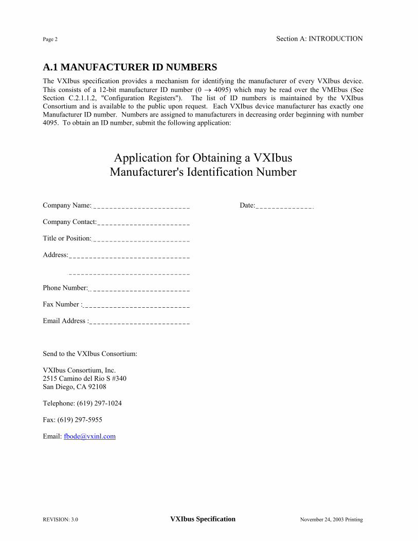
A.1 MANUFACTURER ID NUMBERS
The VXIbus specification provides a mechanism for identifying the manufacturer of every VXIbus device. This consists of a 12-bit manufacturer ID number (0 → 4095) which may be read over the VMEbus (See Section C.2.1.1.2, "Configuration Registers"). The list of ID numbers is maintained by the VXIbus Consortium and is available to the public upon request. Each VXIbus device manufacturer has exactly one Manufacturer ID number. Numbers are assigned to manufacturers in decreasing order beginning with number 4095. To obtain an ID number, submit the following application:
Application for Obtaining a VXIbus
Manufacturer's Identification Number
Company Name: Date: Company Contact: Title or Position: Address: Phone Number: Fax Number : Email Address : Send to the VXIbus Consortium: VXIbus Consortium, Inc. 2515 Camino del Rio S #340 San Diego, CA 92108 Telephone: (619) 297-1024 Fax: (619) 297-5955 Email: [email protected]

Section A: INTRODUCTION Page 3
November 24, 2003 Printing VXIbus Specification REVISION: 3.0
A.2 VXIbus OVERVIEW A.2.1 Introduction
The goal of the VXIbus is to define a technically sound modular instrument specification based on the VMEbus that is open to all manufacturers and is compatible with present industry standards.
VXIbus is an acronym for VMEbus Extensions for Instrumentation. The VXIbus specification details the technical requirements of VXIbus compatible components, such as mainframes, backplanes, power supplies and modules. Before studying the VXIbus architecture, one should become familiar with the VMEbus and its specification. A.2.2 VMEbus Background
The VMEbus is an open system architecture primarily focused at computer systems, though there presently is a limited offering of instrumentation. VMEbus modules are approximately six inches deep and come in two heights, about four inches and nine inches. The VXIbus specification refers to these as the A and B-sizes respectively. The precise dimensions are specified by the Eurocard standard, which describes a family of printed circuit boards and their associated DIN connector locations. VMEbus modules are designed for 0.8 inch slot-to-slot spacing. The A-size board has a single 96-pin connector known as P1, while the B-size may include a P1 and P2 connector. Each of these DIN connectors consists of three rows of 32 pins apiece on 0.1 inch centers. Typically, these boards are positioned vertically in a frame with the P1 connector closest to the top. Neither the VMEbus nor the VXIbus mandates a physical orientation since orientation is only an implementation issue not needed for compatibility. Many VMEbus systems are designed to accept boards horizontally.
The VMEbus specification allows a maximum of 21 modules. However, if installed vertically in a mainframe intended for mounting in a standard 19 inch rack, 20 is the practical maximum. VMEbus makes no particular provision for an extension chassis or frame-to-frame communication. Multiple frame systems can be created by electrically buffering the VMEbus (at the loss of some bandwidth between cages) or by using standard data communication links that disguise the underlying VMEbus architecture. There are no EMC (electromagnetic compatibility) requirements dictated by VMEbus, either conducted or radiated, nor are there power dissipation limits or chassis cooling requirements. VMEbus has left these issues to the system integrator, while VXIbus addresses these issues more rigorously.
Although electrically and logically similar to the 68000 microprocessor architecture, the VMEbus interface has been specified broadly enough that it is not dependent on any particular processor and many processors are already supported on VMEbus, including the 80386. Many of the simpler VMEbus boards do not have processors at all.
A minimum VMEbus system requires only the P1 connector. All handshaking, arbitration and interrupt support exists on P1, with P2 used to expand the system to 32 bits of address and data (A32 and D32). P1 will support 16-bit and 24-bit addressing (A16 and A24), as well as 8- and 16-bit data paths (D08 and D16). The extra lines needed for A32 and D32 are contained on the center row of P2, while the outer rows are user defined. These undefined pins are typically used for interface connections, such as allowing a module to drive a chassis mounted connector, access an internal disk drive or provide for module-to-module communication. VSB (VMEbus Subsystem Bus) is a standard "subsystem bus" that has defined P2 as an additional communication path for up to six modules. Multiple VSBs may exist within any one VMEbus system. This is important to note, because VXIbus defines a subsystem of up to thirteen modules and, like VSB, multiple VXIbus subsystems may exist within any one VXIbus system.
Page 4 Section A: INTRODUCTION
REVISION: 3.0 VXIbus Specification November 24, 2003 Printing
A.2.3 The VXIbus Extensions
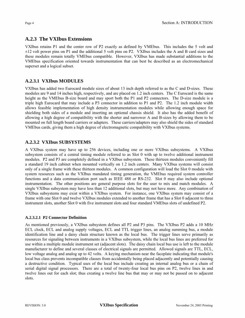
VXIbus retains P1 and the center row of P2 exactly as defined by VMEbus. This includes the 5 volt and ±12 volt power pins on P1 and the additional 5 volt pins on P2. VXIbus includes the A and B card sizes and these modules remain totally VMEbus compatible. However, VXIbus has made substantial additions to the VMEbus specification oriented towards instrumentation that can best be described as an electromechanical superset and a logical subset. A.2.3.1 VXIbus MODULES
VXIbus has added two Eurocard module sizes of about 13 inch depth referred to as the C and D-sizes. These modules are 9 and 14 inches high, respectively, and are placed on 1.2 inch centers. The C Eurocard is the same height as the VMEbus B-size board and may sport both the P1 and P2 connectors. The D-size module is a triple high Eurocard that may include a P3 connector in addition to P1 and P2. The 1.2 inch module width allows feasible implementation of high density instrumentation modules while allowing enough space for shielding both sides of a module and inserting an optional chassis shield. It also has the added benefit of allowing a high degree of compatibility with the shorter and narrower A and B-sizes by allowing them to be mounted on full length board carriers or adapters. These carriers/adapters may also shield the sides of standard VMEbus cards, giving them a high degree of electromagnetic compatibility with VXIbus systems. A.2.3.2 VXIbus SUBSYSTEMS
A VXIbus system may have up to 256 devices, including one or more VXIbus subsystems. A VXIbus subsystem consists of a central timing module referred to as Slot 0 with up to twelve additional instrument modules. P2 and P3 are completely defined in a VXIbus subsystem. These thirteen modules conveniently fill a standard 19 inch cabinet when mounted vertically on 1.2 inch centers. Many VXIbus systems will consist only of a single frame with these thirteen modules. A common configuration will load the Slot 0 module with system resources such as the VXIbus mandated timing generation, the VMEbus required system controller functions and a data communication port such as IEEE 488 or RS-232. Slot 0 may also include optional instrumentation. The other positions are general purpose slots for the user to mix and match modules. A single VXIbus subsystem may have less than 12 additional slots, but may not have more. Any combination of VXIbus subsystems may exist within a VXIbus system. For instance, one VXIbus system may consist of a frame with one Slot 0 and twelve VXIbus modules extended to another frame that has a Slot 0 adjacent to three instrument slots, another Slot 0 with five instrument slots and four standard VMEbus slots of undefined P2. A.2.3.2.1 P2 Connector Definition
As mentioned previously, a VXIbus subsystem defines all P2 and P3 pins. The VXIbus P2 adds a 10 MHz ECL clock, ECL and analog supply voltages, ECL and TTL trigger lines, an analog summing bus, a module identification line and a daisy chain structure known as the local bus. The trigger lines serve primarily as resources for signaling between instruments in a VXIbus subsystem, while the local bus lines are preferred for use within a multiple module instrument set (adjacent slots). The daisy chain local bus use is left to the module manufacturer to define and several classes of electrical signals are permitted. Allowed signals are TTL, ECL, low voltage analog and analog up to 42 volts. A keying mechanism near the faceplate indicating that module's local bus class prevents incompatible classes from accidentally being placed adjacently and potentially causing a destructive condition. Typical uses of the local bus include creating an internal analog bus or a chain of serial digital signal processors. There are a total of twenty-four local bus pins on P2, twelve lines in and twelve lines out for each slot; thus creating a twelve line bus that may or may not be passed on to adjacent slots.

Section A: INTRODUCTION Page 5
November 24, 2003 Printing VXIbus Specification REVISION: 3.0
A.2.3.2.2. P3 Connector Definition
The VXIbus P3 connector adds many of the same resource types as described for P2, but is aimed at higher performance instrumentation. Included on P3 is a 100 MHz clock and sync signal, additional power pins of the same supply voltages, more ECL trigger lines and twenty-four additional lines (48 pins) of daisy chain local bus. Also defined on P3 is a "star" trigger system where precision ECL trigger signals are routed through Slot 0 acting as a cross point switch. This allows very precisely matched trigger timing between modules regardless of module position. A.2.3.3 VXIbus SYSTEM ARCHITECTURE
The VXIbus device protocols define how modules are granted non-conflicting portions of the VMEbus address space. A device is typically a single module, but this is not required. Several devices may exist on a single module and a single device may consist of multiple modules. 256 devices may exist in any one VXIbus system and are referred to by logical device addresses ranging from 0 to 255. A VXIbus system configuration space is defined in the upper 16k of the 64k A16 address space. Each device is granted a total of 64 bytes in this space, which is sufficient for many of the simpler devices. Devices requiring additional address space have their address requirements readable in a defined register in the A16 address space. A "resource manager" reads this value shortly after power-on and then assigns the requested memory space by writing the module's new VMEbus address into the device's offset register. This method positions a device's additional memory space in the A24 (16 Mbyte), A32 (4 Gbyte), or A64 (18 Ebyte) address space. If present day VMEbus cards are used in a system, the resource manager must position the VXIbus devices around the space taken by the standard VMEbus cards.
Higher level communication protocols are defined to allow sharing of interface modules and other devices by multiple manufacturers. A.2.3.4 VXIbus SPECIFICATION STRUCTURE
In structure, the VXIbus specification parallels much of the VMEbus C.1 specification. Some VXIbus specification sections have the same titles as the VMEbus chapters. Other sections are devoted to topics not addressed by the VMEbus specification. The VXIbus document contains more than just the rules needed for VXIbus compliance; included are design tips and suggestions added to help the designer create compatible components. The same format of RULES, RECOMMENDATIONS, SUGGESTIONS and OBSERVATIONS as VMEbus is used. As experience is gained creating VXIbus devices and using the specification, appropriate updates to the specification will occur.

Page 6 Section A: INTRODUCTION
REVISION: 3.0 VXIbus Specification November 24, 2003 Printing
A.3 DOCUMENT STRUCTURE
This document is organized in sections, with each section discussing a particular independent level of the implementation. In the event where a section parallels another standard document (such as VMEbus) subsections will have corresponding numbers. Several appendices, containing clarifications and extensions, follow the body of the specification. A.4 SPECIFICATION OBJECTIVES
This document defines a set of RULES and RECOMMENDATIONS for constructing a component which will interface to the VXIbus Family. The specifications cover the complete spectrum from basic hardware issues such as card dimensions to recommendations for communications protocols. This specification has the following objectives:
1. To allow communication among devices in an unambiguous fashion.
2. To allow for physical size reduction of standard Rack&stack instrumentation systems.
3. To allow for software cost reduction in test system integration by the use of common interfaces to analogous capabilities.
4. To provide higher system throughput for test systems through the use of higher bandwidth channels for inter-device communication and the use of new protocols specifically designed to enhance throughput.
5. To provide test equipment which could be used in military IAC (Instrument on a Card) systems.
6. To provide the ability to implement new functionality in test systems through the use of virtual instruments.
7. To define how to implement Multi-module Instruments within the framework of this specification.

Section A: INTRODUCTION Page 7
November 24, 2003 Printing VXIbus Specification REVISION: 3.0
A.5 DEFINITION of TERMS
Throughout this document you will see the following headings on paragraphs. These headings identify the contents of the paragraph:
RULE: Rules SHALL be followed to ensure compatibility for cards in the system. A rule is characterized by the use of the words SHALL and SHALL NOT. These words are not used for any other purpose other than stating rules.
RECOMMENDATION: Recommendations consist of advice to implementers which will affect the usability of the final device. Discussions of particular hardware to enhance throughput would fall under a recommendation. These should be followed to avoid problems and to obtain optimum performance.
SUGGESTION: A suggestion contains advice which is helpful but not vital. The reader is encouraged to consider the advice before discarding it. Suggestions are included to help the novice designer with areas of design that can be problematic.
PERMISSION: Permissions are included to clarify the areas of the specification that are not specifically prohibited. Permissions reassure the reader that a certain approach is acceptable and will cause no problems. The word MAY is reserved for indicating permissions.
OBSERVATION: Observations spell out implications of rules and bring attention to things that might otherwise be overlooked. They also give the rationale behind certain rules, so that the reader understands why the rule must be followed.
Any text which appears without heading should be considered as description of the specification.

Page 8 Section A: INTRODUCTION
REVISION: 3.0 VXIbus Specification November 24, 2003 Printing

Section B: VXIbus IMPLEMENTATION of VMEbus SPECS Page 9
November 24, 2003 Printing VXIbus Specification REVISION: 3.0
B. VXIbus IMPLEMENTATION of VMEbus SPECS
This document describes additions to and recommendations for the VMEbus specifications,[1] also known as VME64, and for Chapter 11 of the VME64 Extensions,[5] also known as VME64x. This section is organized in a parallel fashion to the ANSI/VITA VME64/VME64x specification documents. Sections B.1 - B.7 are additions to the corresponding VME64 Chapters 1-7. Section B.8 is unique to VXIbus and has no corresponding VME64 chapter. Section B.11 is an addition to Chapter 11 of VME64x. B.1. INTRODUCTION
The intent of the VXIbus Implementation of the VMEbus specifications is to produce an electro-mechanical superset and logical subset of the VME64 specifications in order to establish compatibility for all VXIbus systems. It is expected that most boards designed to the VME64 specification will be compatible with this implementation mechanically and electrically. However, a subset of VME64 Protocols relating to data transfer, arbitration and interrupts has been specified and may limit the utility of some standard VME64 products in a VXIbus system. Mechanical extensions are defined to allow for a superset of board sizes. B.2 DATA TRANSFER BUS B.2.1 Address Modifiers
RECOMMENDATION B.2.1: The following VME64 address modifiers should not be used in VXIbus systems:
0416, 0516, 2C16, 3216, 3516 (Lock commands);
1016 - 1F16 (User Defined);
2016 with XAM codes, 1116, 1216, 2116, 2216 (6U 2eSST Transfers);
2116 with XAM codes 0116, 0216, 1116, 1216, 2116, 2216 (3U 2eVME and 2eSST Transfers);
2F16 (CR/CSR);
3416, 3716 (A40 transfers).
OBSERVATION B.2.1: The intent of the preceding restrictions is to increase interoperability between masters and slaves in VXIbus systems.
OBSERVATION B.2.2: XAM codes are “Extended Address Modifier codes”. These are defined in VME64x and in 2eSST,[6] (ANSI/VITA 1.5-2003), they are used to select 2eVME or 2eSST cycles on the backplane. 3U 2eVME operation is not recommended because for full functionality, the 160-pin connector must be used. 2eSST was not considered for the 3.0 release of the VXI specification and therefore its use is undefined for the VXIbus. B.2.2 DTACK*, BERR* and RETRY* Operation
For highest performance, VXIbus slaves should respond to register accesses as fast as possible, by sourcing/accepting data and asserting DTACK* immediately. Sometimes a register may be busy, temporarily unable to source or accept data. In this case the slave should assert RETRY* to indicate the busy condition to the bus master. If either device does not support RETRY*, the slave may wait for up to 20 µs for the register

Page 10 Section B: VXIbus IMPLEMENTATION of VMEbus SPECS
REVISION: 3.0 VXIbus Specification November 24, 2003 Printing
to become ready. If the register becomes ready within this time, the slave will source/accept the data and assert DTACK*. Otherwise, it will end the cycle by asserting BERR*.
VXIbus slaves are not allowed to exhibit deadlocks, when a register is not accessible to another VXIbus master because the slave device itself is waiting to become bus master. Any such conflict is to be resolved in favor of the current bus master.
RECOMMENDATION B.2.2: During an attempted access of one of its implemented registers, a VXIbus SLAVE should normally drive DTACK* low within 100 ns after a data strobe goes low.
OBSERVATION B.2.3: The intent of the preceding recommendation is to maximize overall system performance by encouraging designers to implement all low level handshaking in fast hardware.
RECOMMENDATION B.2.3: During an attempted access of a busy register, a VXIbus SLAVE should drive RETRY* low within 100 ns after a data strobe goes low.
RULE B.2.1: During an attempted access of one of its implemented registers, a VXIbus SLAVE SHALL drive DTACK* or BERR* low within 20 µs after a data strobe goes low, if the cycle has not already been terminated by the VXIbus MASTER in response to a RETRY* assertion.
RULE B.2.2: Addressed VXIbus SLAVES SHALL release DTACK*, BERR* and RETRY* high within 5 µs after the data strobe(s) goes high.
RECOMMENDATION B.2.4: Addressed VXIbus SLAVES should release DTACK*, BERR* and RETRY* high within 0.1 µs after the data strobe(s) goes high.
RULE B.2.3: During an access to a deadlocked register, the VXIbus SLAVE SHALL terminate its own contention for bus mastership and allow the current VXIbus MASTER immediate access to the deadlocked register.
RECOMMENDATION B.2.5: A SLAVE should implement the Rescinding DTACK* described in Section 2.2.4.3.1 of the VME64 specification.
OBSERVATION B.2.4: Devices participating in 2eVME transactions are required to meet the additional timing requirements called out in Section B.11, “2eVME Protocol.” B.2.3 CR/CSRs
The VME64 specification (see Section 2.3.12) defines an address space accessing VME64 Configuration ROM / Control and Status Register (CR/CSR) resources. This CR/CSR capability has overlapping functionality with the Configuration and Communication registers defined in Section C of this specification. The VXIbus specification does not include these CR/CSRs.
RULE B.2.4: VXIbus devices SHALL NOT rely on VME64 CR/CSRs for proper operation.

Section B: VXIbus IMPLEMENTATION of VMEbus SPECS Page 11
November 24, 2003 Printing VXIbus Specification REVISION: 3.0
B.2.4 Bus Timer Operation
RULE B.2.5: The BUS TIMER SHALL be BTO (≥100). BTO units are in µs.
OBSERVATION B.2.5: The BTO(100) capability minimum is to allow for chassis to chassis communication. There is a potential for each chassis to take up to 20 µs to respond to a data transfer. B.3 DATA TRANSFER BUS ARBITRATION
RULE B.3.1: The BUS GRANT daisy-chain lines SHALL be used or passed by all single boards and board assemblies.
RECOMMENDATION B.3.1: The arbiter should implement priority based arbitration between the 4 Bus Request/Grant levels. B.4 PRIORITY INTERRUPT
RULE B.4.1: The INTERRUPT ACKNOWLEDGE daisy-chain lines SHALL be used or passed by all single boards and board assemblies. B.5 UTILITIES B.5.1 Power Monitor The POWER MONITOR is a VME64 function which asserts the SYSRESET* line at power-on and asserts both the ACFAIL* and SYSRESET* lines immediately prior to power-removal. Although this is an optional VME64 capability which may reside on the system controller board, it is a required VXIbus capability closely linked to the mainframe power supply. Therefore, each mainframe is required to provide this function.
RULE B.5.1: Every VXIbus mainframe SHALL provide a VME64 POWER MONITOR.
RECOMMENDATION B.5.1: A power monitor should drive ACFAIL* low a minimum of 8 ms before driving SYSRESET* low and a minimum of 10 ms before +5 VDC power drops below 4.875 volts, when a power failure is detected. See Figure 5-4 of the VME64 specification.
The VME64 specification defines relationships between the SYSRESET*, ACFAIL* and +5 V signals. In VXIbus systems, relationships to other signals are also important.
RULE B.5.2: At power-on, all VXIbus defined power supplies SHALL be within specification at least 2 milliseconds before SYSRESET* transitions to the unasserted (High) state, under all rated load conditions.
OBSERVATION B.5.1: The VME64 specification requires that the +5 V power supply be within specification at least 200 ms before SYSRESET* becomes unasserted.
RECOMMENDATION B.5.2: A module that requires specific sequencing of the power supplies should provide its own power sequencer. Such a sequencer should start its operation after it detects SYSRESET* unasserted.

Page 12 Section B: VXIbus IMPLEMENTATION of VMEbus SPECS
REVISION: 3.0 VXIbus Specification November 24, 2003 Printing
OBSERVATION B.5.2: Module designers can not depend on the transient behaviors of VXIbus mainframes during power-up. The relative sequencing, slew rates, monotonic transitions, etc of the various power supplies are not specified.
RULE B.5.3: At power-on, the SYSCLK and CLK10 signals SHALL be within specification before SYSRESET* transitions to the unasserted (High) state.
OBSERVATION B.5.3: The clock generation circuits are guaranteed at least 2 milliseconds for stabilization in the interval after the power supplies are within specification and before SYSRESET* becomes unasserted.
PERMISSION B.5.1: A Slot 0 module that requires more than 2 milliseconds for its SYSCLK and CLK10 generators to stabilize MAY assert SYSRESET* during power-on sequencing until the clock signals are within specification. B.5.2 Power Pins
See Section B.8, "EMC and System Power", for power pin specifications. B.5.3 Auto Slot ID
VME64 defines a mechanism to determine the relative slot positions of cards and assign CSR base addresses to those cards. This Auto Slot ID function is incompatible with VXIbus requirements.
RULE B.5.4: VXIbus devices SHALL NOT implement the VME64 Auto Slot ID function.
OBSERVATION B.5.4: VXIbus uses MODID signals to determine the slot positions of modules (See Section B.6.2.2, "MODID Lines"). VXIbus also defines a mechanism for assigning logical addresses, based on slot positions (See Section F, "Dynamic Configuration"). B.5.4 Auto System Controller
VME64 defines an automatic means for a device to detect whether it is in VMEbus Slot 1, allowing it to automatically enable its system controller functions.
OBSERVATION B.5.5: The VME64 system controller and VXIbus Slot 0 functions usually reside in the same module/slot. However, the VXIbus specification allows the implementation of segmented backplanes, which may separate these functions.
PERMISSION B.5.2: VXIbus devices MAY implement the VME64 Auto System Controller detection scheme.
RECOMMENDATION B.5.3: VXIbus modules should not use the VME64 Auto System Controller detection to enable/disable Slot 0 functions, nor use the VXIbus MODID signals to enable/disable VME64 system controller functions.

Section B: VXIbus IMPLEMENTATION of VMEbus SPECS Page 13
November 24, 2003 Printing VXIbus Specification REVISION: 3.0
B.6 ELECTRICAL SPECIFICATIONS
RULE B.6.1: All conductors on P1, P2 and P3 SHALL meet the requirements of Section 6.1 of the VME64 (VITA 1-1994) specification.
OBSERVATION B.6.1: In order to meet backplane shielding requirements, only standard DIN 41612 Class II, Style C, 3 row, 96-pin connectors shall be used for P1, P2 and P3. See Rules B.7.44-49 and Recommendation B.7.11. B.6.1 The P1 Connector
All the signals on the 96-pin P1 connector are defined by the VME64 specification. B.6.2 The VXIbus Subsystem P2 Connector
The VXIbus subsystem bus defines the outer rows, a and c (user defined pins), of the 96-pin P2 connector for instrumentation use. The center row (b) signals are defined by VME64. Alternate definitions of the outer two rows of P2 are permitted in VXIbus systems (not VXIbus subsystems) with a "Segmented Backplane" architecture where other VME64 subsystem buses, such as VSB, may exist. A VXIbus subsystem bus consists of a system resource module defined as Slot 0 with up to twelve adjacent modules in increasing slot numbers. VXIbus and VXIbus subsystem bus are used interchangeably in this section of the VXIbus specification.
The VXIbus P2 connector delivers resources to modules particularly oriented toward instrumentation. On P2 it adds:
-5.2 V, -2 V, ±24 V and additional +5 V power.
10 MHz differential clock.
2 parallel ECL trigger lines.
8 parallel TTL trigger lines.
Module identification pin.
12 lines of manufacturer defined local bus lines that connect to adjacent modules.
50 Ω terminated analog summing bus.
The Slot 0 module serves as a system resource and has a modified P2 functionality for central handling of the module identification pins. The Slot 0 Module, while providing these common resources, may also contain other devices and instrumentation. B.6.2.1 CLK10
CLK10 is a 10 MHz system clock. It is sourced from Slot 0 and distributed to Slots 1-12 on P2. The Slot 0 output is differential ECL. It is buffered on the backplane and distributed to each module slot as a single source, single destination differential ECL signal. The CLK10 is individually buffered on the backplane for each slot position to provide a high level of inter-module isolation and relax the loading rules for modules. See Figure B.1.

Page 14 Section B: VXIbus IMPLEMENTATION of VMEbus SPECS
REVISION: 3.0 VXIbus Specification November 24, 2003 Printing
PIN
NUMBER
ROWa SIGNAL
MNEMONIC
ROWb SIGNAL
MNEMONIC
ROWc SIGNAL
MNEMONIC
PIN
NUMBER 1 2 3 4 5 6 7 8 9
10 11 12 13 14 15 16 17 18 19 20 21 22 23 24 25 26 27 28 29 30 31 32
ECLTRG0 -2 V
ECLTRG1 GND
LBUSA00 LBUSA01
-5.2 V LBUSA02 LBUSA03
GND LBUSA04 LBUSA05
-5.2 V LBUSA06 LBUSA07
GND LBUSA08 LBUSA09
-5.2 V LBUSA10 LBUSA11
GND TTLTRG0* TTLTRG2*
+5 V TTLTRG4* TTLTRG6*
GND RSV2
MODID GND
SUMBUS
+5 V GND
RETRY* A24 A25 A26 A27 A28 A29 A30 A31 GND +5 V D16 D17 D18 D19 D20 D21 D22 D23 GND D24 D25 D26 D27 D28 D29 D30 D31 GND +5 V
CLK10+ CLK10-
GND -5.2 V
LBUSC00 LBUSC01
GND LBUSC02 LBUSC03
GND LBUSC04 LBUSC05
-2 V LBUSC06 LBUSC07
GND LBUSC08 LBUSC09
-5.2 V LBUSC10 LBUSC11
GND TTLTRG1* TTLTRG3*
GND TTLTRG5* TTLTRG7*
GND RSV3 GND +24 V -24 V
1 2 3 4 5 6 7 8 9
10 11 12 13 14 15 16 17 18 19 20 21 22 23 24 25 26 27 28 29 30 31 32
TABLE B.1 P2 Pin Definitions: Slots 1-12
RULE B.6.2: The CLK10 frequency sourced from Slot 0 SHALL be 10 MHz. Its accuracy SHALL be equal to or better than ±100 ppm (0.01%), over its specified operating temperature and time.
RECOMMENDATION B.6.1: A Slot 0 module should allow CLK10 to be derived from an external frequency source.

Section B: VXIbus IMPLEMENTATION of VMEbus SPECS Page 15
November 24, 2003 Printing VXIbus Specification REVISION: 3.0
PIN
NUMBER
ROWa SIGNAL
MNEMONIC
ROWb SIGNAL
MNEMONIC
ROWc SIGNAL
MNEMONIC
PIN
NUMBER 1 2 3 4 5 6 7 8 9
10 11 12 13 14 15 16 17 18 19 20 21 22 23 24 25 26 27 28 29 30 31 32
ECLTRG0 -2 V
ECLTRG1 GND
MODID12 MODID11
-5.2 V MODID10 MODID09
GND MODID08 MODID07
-5.2 V MODID06 MODID05
GND MODID04 MODID03
-5.2 V MODID02 MODID01
GND TTLTRG0* TTLTRG2*
+5 V TTLTRG4* TTLTRG6*
GND RSV2
MODID00 GND
SUMBUS
+5 V GND
RETRY* A24 A25 A26 A27 A28 A29 A30 A31 GND +5 V D16 D17 D18 D19 D20 D21 D22 D23 GND D24 D25 D26 D27 D28 D29 D30 D31 GND +5 V
CLK10+ CLK10-
GND -5.2 V
LBUSC00 LBUSC01
GND LBUSC02 LBUSC03
GND LBUSC04 LBUSC05
-2 V LBUSC06 LBUSC07
GND LUBSC08 LBUSC09
-5.2 V LBUSC10 LBUSC11
GND TTLTRG1* TTLTRG3*
GND TTLTRG5* TTLTRG7*
GND RSV3 GND +24 V -24 V
1 2 3 4 5 6 7 8 9
10 11 12 13 14 15 16 17 18 19 20 21 22 23 24 25 26 27 28 29 30 31 32
TABLE B.2. P2 Pin Definitions: Slot 0
OBSERVATION B.6.2: An external frequency source would permit the use of an accurate frequency reference, such as a Rubidium Standard and would facilitate synchronization of multiple VXIbus mainframes.
RULE B.6.3: CLK10 duty cycle SHALL be 50% ±5% when measured at the 50% transition level.

Page 16 Section B: VXIbus IMPLEMENTATION of VMEbus SPECS
REVISION: 3.0 VXIbus Specification November 24, 2003 Printing
Figure B.1. CLK10, MODID and LBUS backplane signal routing RULE B.6.4: IF CLK10 is switched between different clock sources, THEN the minimum pulse width, high or low, SHALL NOT be less than 30 ns or more than 10 µs during switching. The minimum time between two successive transitions of the same polarity SHALL NOT be less than 80 ns.
RULE B.6.5: Each slot's CLK10 SHALL be differentially driven by a unique backplane buffer output.
825
MODID 00 MODIDMODID
- + CLK10
- +CLK10
- +CLK10
SLOT 0 SLOT 1 SLOT 2
MODID 01-12
LBUSC
LBUS LBUSA C
-2 V
50Ω
50Ω
LBUS LBUSA C

Section B: VXIbus IMPLEMENTATION of VMEbus SPECS Page 17
November 24, 2003 Printing VXIbus Specification REVISION: 3.0
RULE B.6.6: CLK10 SHALL be differentially driven onto the CLK10+ and CLK10- pins by the module in Slot 0.
RULE B.6.7: The backplane CLK10 distribution traces SHALL be designed for 50 Ω.
RULE B.6.8: IF a module accesses the CLK10 signals, THEN it SHALL provide 50 Ω termination on CLK10+ and CLK10-, with no more than two (2) equivalent ECL loads.
RULE B.6.9: The absolute delay of CLK10 from Slot 0 to any module SHALL NOT exceed 8 ns.
OBSERVATION B.6.3: Either single ended input buffers or differential input buffers can be used to buffer and fan out CLK10 on the backplane. Typical components are the 10H101 and 10H116 buffers. Single ended input buffers may be connected to either of the CLK10+ or CLK10- signals sourced by the module in Slot 0. B.6.2.2 MODID LINES
The MODID lines allow a logical device to be identified with a particular physical location or slot. These lines are sourced from the VXIbus Slot 0 module to the Slot 1 and higher modules. There is one line to each module, located on P2 pin A30. A total of twelve MODID lines will connect between Slot 0 and the other modules in a maximally configured VXIbus subsystem. In addition to these twelve lines, Slot 0 has its own MODID line (MODID00). The purpose of the MODID lines is to:
1. Detect the presence of a module in a slot, even if that module has failed.
2. Identify the geographical location (slot number) of a particular device.
3. Indicate by lamp or other means the actual physical location of the module.
Slot 0 detects the presence of a module by the module pulling down its MODID line with a fixed resistor to ground. This allows any module, even if failed and unpowered, to be detected.
The slot number of a device is identified by the Slot 0 module asserting a particular MODID line and polling the MODID bit in each module's A16 configuration space to detect the selected device.
A visual indicator, such as a lamp, may be placed adjacent to a slot (or even on the module) to illuminate when that particular MODID line is driven true. This may be used to quickly identify the location of any module, including failed modules. Refer to Figure B.1 for rules for loading and driving the MODID lines.
RULE B.6.10: Each Slot 0 MODIDxx receiver SHALL comply with the VME64 loading rules for High Current 3 State lines (VME64 specification, Rule 6.14).
RULE B.6.11 Each Slot 0 MODIDxx driver SHALL comply with the VME64 driving rules for Standard 3 State lines (VME64 specification, Rule 6.15).

Page 18 Section B: VXIbus IMPLEMENTATION of VMEbus SPECS
REVISION: 3.0 VXIbus Specification November 24, 2003 Printing
Figure B.2. Module ID lines RULE B.6.12: Each Slot 0 device SHALL provide a 16.9 kΩ pull up resistor from each MODID line to +5 volts.
RULE B.6.13: IF a non-Slot 0 module accesses the MODID pin, THEN it SHALL provide an 825 Ω pull down to ground in parallel with no more than 100 µA of leakage current on its MODID line.
OBSERVATION B.6.4: 16.9 kΩ and 825 Ω are standard 1% metal film resistor values.
RULE B.6.14: A VXIbus subsystem backplane SHALL provide an 825 Ω pull down to ground on the MODID00 line.
RULE B.6.15: The backplane SHALL NOT sink or source more than 100 µA of leakage current to any MODID line.
PERMISSION B.6.1: A VXIbus subsystem Slot 0 module MAY drive its MODID line true to illuminate its own module location lamp.
OBSERVATION B.6.5: The proper placement of a Slot 0 module in a Slot 0 position may be verified by a read of its MODID00 state when all Slot 0 MODID drivers are disabled. A low state indicates that the module is in a Slot 0 position. A high state indicates that it is in another position.
MODID 02
MODID 01
MODID 00
IIL <0.1 mA
825
ID
IIL <0.1 mA
May drive slot identification
Lamps adjacent to module location.
+5 V
16.9 k
+5 V
16.9 k
IIL <0.1 mA
825
VXI Subsystem Slot 0 VXI Subsystem Slot 1 VXI Subsystem Slot 2
ID

Section B: VXIbus IMPLEMENTATION of VMEbus SPECS Page 19
November 24, 2003 Printing VXIbus Specification REVISION: 3.0
B.6.2.3 TTLTRG0-7* (TTL TRIGGER LINES)
The TTLTRG* lines are open collector TTL lines used for intermodule communication. Any module, including Slot 0, may drive these lines and receive information on these lines. They are general purpose lines that may be used for trigger, handshake, clock or logic state transmission. They are in a non-asserted (high) state until allocated by the user under program control. Some standard allocation procedures are defined. Standard protocols, synchronous (SYNC), asynchronous (ASYNC) and start/stop (STST) are defined. To compensate for the larger rise time caused by the passive pullup termination, these protocols specify separate timing requirements for trigger sources and trigger acceptors. When used for logic state transmission, setup and hold times with respect to a clock edge are defined. Other protocols may be defined by a manufacturer.
OBSERVATION B.6.6: The VME64 specification recommends a 100 Ω system impedance for open collector lines. Although the TTLTRG* lines will be terminated and meet the drive and load requirements for VME64, the characteristic impedance of the traces on the backplane may be closer to 50 Ω. This allows ECL traces to share the same backplane layer and may keep backplanes at a manufacturable number of planes and thickness for component insertion. This should not significantly affect performance of the TTLTRG* lines.
RULE B.6.16: The backplane SHALL terminate all TTLTRG* lines as specified by the VME64 specification, Figure 6-2, Standard Bus Termination.
RULE B.6.17: A module's interface to any TTLTRG* signal line SHALL conform to the driving and loading rules for open collector lines (VME64 specification, Section 6.4.2.5).
RULE B.6.18: All TTLTRG* line drivers SHALL be unasserted within one (1) second after SYSRESET* becomes unasserted.
RULE B.6.19: A module SHALL allocate any TTLTRG* lines to specific functions in groups of 1, 2 or 4.
RULE B.6.20: IF a module uses single line TTLTRG* groups, THEN that module SHALL be user-programmable to connect to any TTLTRG* line.
RULE B.6.21: IF a module uses two line TTLTRG* groups, THEN that module SHALL be user programmable to connect all defined TTLTRG* group pairs. The defined TTLTRG* group pairs are lines 0 and 1, lines 2 and 3, lines 4 and 5 and lines 6 and 7.
RULE B.6.22: IF a module uses four line TTLTRG* groups, THEN that module SHALL be user-programmable to connect to all defined TTLTRG* four line groups. The defined TTLTRG* four line group are lines 0, 1, 2 and 3; and lines 4, 5, 6 and 7.

Page 20 Section B: VXIbus IMPLEMENTATION of VMEbus SPECS
REVISION: 3.0 VXIbus Specification November 24, 2003 Printing
B.6.2.3.1 Standard TTLTRG* Protocols B.6.2.3.1.1 TTLTRG* SYNCHRONOUS (SYNC) TRIGGER PROTOCOL
The TTLTRG* SYNC trigger protocol is a single line broadcast trigger that does not require an acknowledge from any acceptors.
RULE B.6.23: A TTLTRG* SYNC trigger source SHALL assert the trigger for a minimum time of T1 and SHALL NOT reassert the trigger for a minimum time of T2 as shown in Figure B.3.
Parameter
Label Min Max Description
T1 T2
30 ns 50 ns
Minimum source assertion time Minimum source non-assertion time
Figure B.3. TTLTRG* Synchronous (SYNC) Trigger Protocol RULE B.6.24: A TTLTRG* SYNC trigger acceptor SHALL accept any trigger asserted for ≥10 ns, following a ≥10 ns unassertion. B.6.2.3.1.2 TTLTRG* ASYNCHRONOUS (ASYNC)TRIGGER PROTOCOL
The TTLTRG* ASYNC trigger protocol is a two line single source, single acceptor protocol. The source initiates an operation by asserting the lower numbered line of the allocated TTLTRG* line pair, while the acceptor acknowledges by asserting the higher numbered line of the TTLTRG* line pair. This is a useful trigger mode for handshaking between VXIbus modules and external instruments or between VXIbus mainframes.
RULE B.6.25: A module implementing the TTLTRG* ASYNC trigger protocol SHALL source only on the lower numbered line of a TTLTRG* line pair.
RULE B.6.26: A module implementing the TTLTRG* ASYNC trigger protocol SHALL acknowledge only on the higher numbered line of a TTLTRG* line pair.
0.8 V2.0 V Source 2.0 V
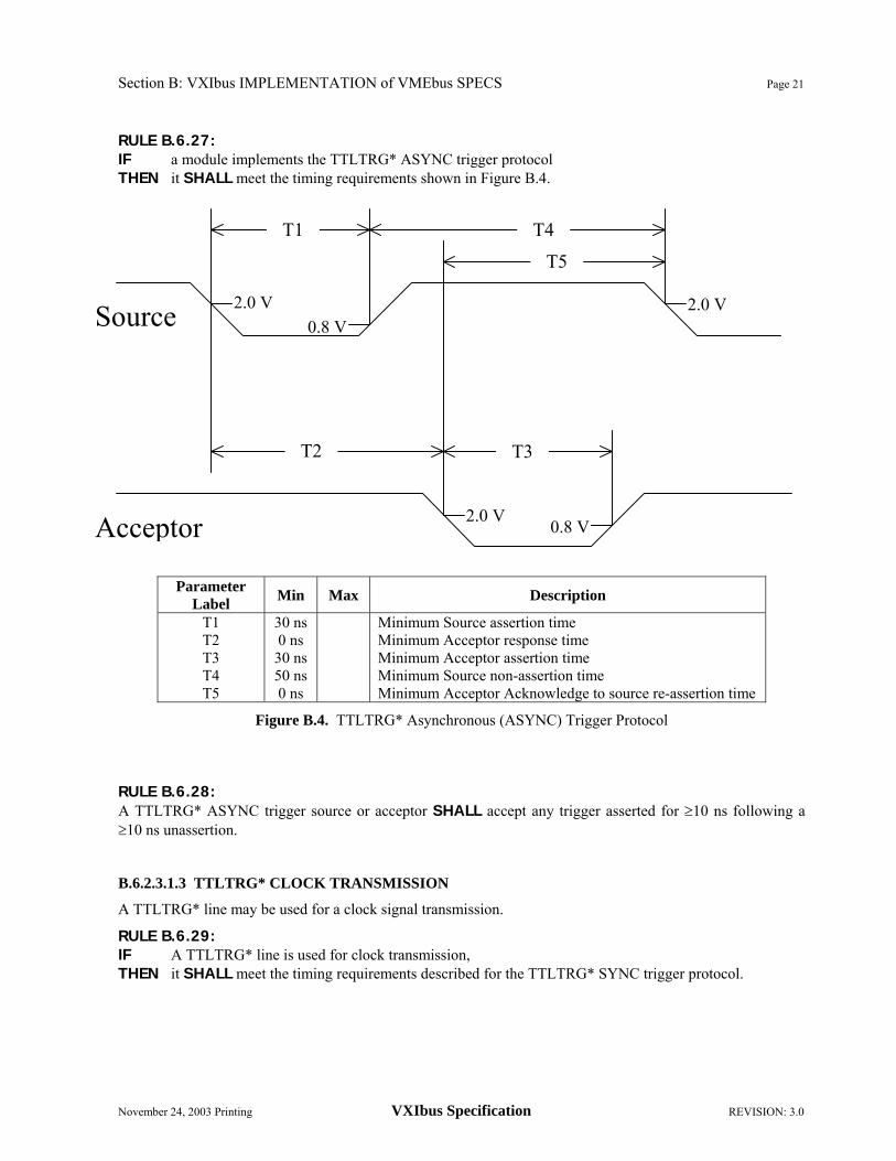
Section B: VXIbus IMPLEMENTATION of VMEbus SPECS Page 21
November 24, 2003 Printing VXIbus Specification REVISION: 3.0
RULE B.6.27: IF a module implements the TTLTRG* ASYNC trigger protocol THEN it SHALL meet the timing requirements shown in Figure B.4.
Parameter Label Min Max Description
T1 T2 T3 T4 T5
30 ns 0 ns
30 ns 50 ns 0 ns
Minimum Source assertion time Minimum Acceptor response time Minimum Acceptor assertion time Minimum Source non-assertion time Minimum Acceptor Acknowledge to source re-assertion time
Figure B.4. TTLTRG* Asynchronous (ASYNC) Trigger Protocol RULE B.6.28: A TTLTRG* ASYNC trigger source or acceptor SHALL accept any trigger asserted for ≥10 ns following a ≥10 ns unassertion. B.6.2.3.1.3 TTLTRG* CLOCK TRANSMISSION
A TTLTRG* line may be used for a clock signal transmission.
RULE B.6.29: IF A TTLTRG* line is used for clock transmission, THEN it SHALL meet the timing requirements described for the TTLTRG* SYNC trigger protocol.
Source
0.8 V
0.8 V
2.0 V
2.0 V2.0 V
Acceptor
T2
T4T1
T5
T3

Page 22 Section B: VXIbus IMPLEMENTATION of VMEbus SPECS
REVISION: 3.0 VXIbus Specification November 24, 2003 Printing
OBSERVATION B.6.7: In a fully loaded VXIbus subsystem, the TTLTRG* rise time will approach 40 nanoseconds. For this reason, the falling edge is used for triggering. B.6.2.3.1.4 TTLTRG* DATA TRANSMISSION
The TTLTRG* lines can also be used for data transmission, where one of the TTLTRG* lines is used as a clock. Data may be synchronized to either the rising or falling edge of the clock or both.
RULE B.6.30: IF a source uses TTLTRG* lines for data transmission on a falling clock edge, THEN the source SHALL meet the timing requirements shown in Figure B.5.
Parameter Label Min Max Description
T1 T2
40 ns 10 ns
Data setup time Data hold time
Figure B.5. TTLTRG* Data Transmission on falling clock edge RULE B.6.31: IF a source uses TTLTRG* lines for data transmission on a rising clock edge, THEN the source SHALL meet the timing requirements shown in Figure B.6. RULE B.6.32: A TTLTRG* data acceptor SHALL accept any data having data setup and hold times of ≥7 ns each.
0.8 V0.8 V
2.0 V
2.0 V2.0 V
Trigger or Clock
T1 T2

Section B: VXIbus IMPLEMENTATION of VMEbus SPECS Page 23
November 24, 2003 Printing VXIbus Specification REVISION: 3.0
Parameter Label Min Max Description
T1 T2
40 ns 40 ns
Data setup time Data hold time
Figure B.6. TTLTRG* Data Transmission on rising clock edge
B.6.2.3.1.5 START/STOP (STST) PROTOCOL
The Start/Stop protocol (STST) provides a method for starting and stopping module clusters synchronously. One TTLTRG* line is driven from the Slot 0 module and its state signifies START or STOP operation. All participating modules respond to this line synchronously at the next CLK10 rising edge. Slot 0 has the responsibility to synchronize the START/STOP signal with CLK10 so that setup and hold times are guaranteed for all acceptors. This may require an arbiter in Slot 0 to synchronize external events.
RULE B.6.33: IF a module implements STST protocol, THEN the START/STOP line SHALL be user-programmable to connect to any TTLTRG* line.
RULE B.6.34: IF a Slot 0 module implements the STST protocol, THEN it SHALL meet the timing requirements shown in Figure B.7.
RULE B.6.35: A TTLTRG* STST acceptor SHALL accept any STST command having data setup and hold times of >7 ns each.
RULE B.6.36: When implementing the STST protocol, START SHALL be represented by a low (asserted) state on the START/STOP TTLTRG* line and STOP SHALL be represented by a high (unasserted) state on the START/STOP TTLTRG* line.
0.8 V0.8 V
0.8 V
2.0 V2.0 V
Trigger or Clock
T1 T2

Page 24 Section B: VXIbus IMPLEMENTATION of VMEbus SPECS
REVISION: 3.0 VXIbus Specification November 24, 2003 Printing
Parameter Label Min Max Description
T1 T2
50 ns 15 ns
START/STOP setup time START/STOP hold time
Figure B.7. TTLTRG* START/STOP timing
B.6.2.3.1.6 EXTERNAL TRIGGER BUFFERING
OBSERVATION B.6.8: The TTLTRG* loading and driving rules require that these lines be buffered when extended outside a mainframe.
RECOMMENDATION B.6.2: When extending a trigger operation external to a VXIbus chassis, the buffer module should source and accept signals as described in the Standard External Trigger Buffer below.
B.6.2.3.1.6.1 Standard External Trigger Buffer
To maximize the compatibility between multiple VXIbus mainframes or a VXIbus mainframe and external instruments, a standard buffering scheme for TTLTRG* lines is recommended. A source has an output series impedance of 50 Ω. Its open circuit low level output is ≤0.4 V and its open circuit high level output is ≥4.2 V. 50 Ω cable is recommended for connection from the source module to other VXIbus mainframes or instruments. For highest performance, terminate the cable with 50 Ω at the furthest point from the source. The acceptor's threshold level is centered at 1.5 V with a loading impedance of ≥5 kΩ. The TTLTRG* sense remains uninverted (Asserted state is low). See Figure B.8.
OBSERVATION B.6.9: The Standard External Trigger Buffer requires only simple buffering to implement the SYNC and ASYNC trigger protocols.
0.8 V0.8 V
-1.29 V
2.0 V2.0 V
START/S
CLK10
T1 T2

Section B: VXIbus IMPLEMENTATION of VMEbus SPECS Page 25
November 24, 2003 Printing VXIbus Specification REVISION: 3.0
Figure B.8. External Trigger Buffering
B.6.2.4 ECLTRG0-1 (ECL TRIGGER LINES)
The ECLTRG lines are intended to be an intermodule timing resource. These two lines are bussed the length of the VXIbus subsystem backplane. Any module, including the Slot 0 module, may drive these lines and receive information from these lines. These lines are single-ended ECL and have a system impedance of 50 Ω. The asserted state is defined as logical high.
RULE B.6.37: Each ECLTRG line SHALL be terminated with 50 Ω to -2 V at each end of the backplane. This requires that any driver be able to drive 25 Ω.
RULE B.6.38: The maximum ECLTRG trace length from the P2 DIN connector pad on any module SHALL NOT exceed 1.0 inch.
RECOMMENDATION B.6.3: The transmission line impedance connecting the P2 DIN connector to the ECLTRG receiver/driver circuitry should be 50 Ω.
RECOMMENDATION B.6.4: A module that senses the ECLTRG lines should have a 150 Ω resistor in series with the transmission line connecting the ECL trigger lines on the P2 DIN connector to the line receiver.
RULE B.6.39: Each module SHALL NOT have more than one equivalent driver/receiver load on any ECLTRG line.
TTLT
RG
* LI
NES
EXTERNAL INSTRUMENT or
VXIbus CHASSIS
TRIGGER IN
TRIGGER OUT
RC
Optional 50 ohm termination BUFFER MODULE in
VXIbus CHASSIS XMIT 50 ohm coax
50 ohm
1.5volts
+
0.4 – 4.2 volts

Page 26 Section B: VXIbus IMPLEMENTATION of VMEbus SPECS
REVISION: 3.0 VXIbus Specification November 24, 2003 Printing
RULE B.6.40: IF a module drives the ECLTRG bus, THEN it SHALL use ECL drivers which provide a LOW output level which is less (more negative) than the -2 V termination supply, e.g. 10H123.
OBSERVATION B.6.10: Using drivers which produce a high impedance LOW level for ECLTRG lines eliminates the glitching which occurs when ECL devices are WIRE-OR'ed.
RULE B.6.41: IF a module connects to an ECLTRG line THEN it SHALL unassert that within one (1) second after SYSRESET* becomes unasserted.
RULE B.6.42: ECLTRG lines SHALL be allocated in groups of 1 or 2 and meet the same allocation rules as defined for the TTLTRG* lines. Figure B.9 shows a typical ECL interface.

Section B: VXIbus IMPLEMENTATION of VMEbus SPECS Page 27
November 24, 2003 Printing VXIbus Specification REVISION: 3.0
Figure B.9. Typical ECLTRG Interface
B.6.2.4.1 Standard ECLTRG Protocols
The ECLTRG lines have a set of defined protocols corresponding to the TTLTRG* protocols. These protocols are defined in the following sections. B.6.2.4.1.1 ECLTRG SYNCHRONOUS (SYNC) TRIGGER PROTOCOL.
The ECLTRG SYNC trigger protocol is a single line broadcast trigger that does not require an acknowledge from any acceptors.
RULE B.6.43: An ECLTRG SYNC trigger source SHALL assert the trigger for a minimum time of T1 and SHALL NOT reassert the trigger for a minimum time of T2 as shown in Figure B.10.
RULE B.6.44: An ECLTRG SYNC trigger acceptor SHALL accept any trigger asserted for ≥6 ns following a ≥6 ns unassertion.
4
3
4
11 2
ECLTRG in
ECLTRG in
3 ECLTRG out 1 0H123
ECLTRGn 150 5
1 0H116

Page 28 Section B: VXIbus IMPLEMENTATION of VMEbus SPECS
REVISION: 3.0 VXIbus Specification November 24, 2003 Printing
Parameter Label Min Max Description
T1 T2
8 ns 8 ns Minimum source assertion time
Minimum source non-assertion time
Figure B.10. ECLTRG Synchronous (SYNC) Trigger Protocol B.6.2.4.1.2 ECLTRG ASYNCHRONOUS (ASYNC) TRIGGER PROTOCOL
The ECLTRG ASYNC trigger protocol is a two line single source, single acceptor protocol. The source initiates an operation by asserting the lower numbered line of the allocated ECLTRG line pair, while the acceptor acknowledges by asserting the higher numbered line of the ECLTRG line pair. This is a useful trigger mode for handshaking between VXIbus modules and external instruments.
RULE B.6.45: A module implementing the ECLTRG ASYNC trigger protocol SHALL source only on the lower numbered line of an ECLTRG line pair.
RULE B.6.46: A module implementing the ECLTRG ASYNC trigger protocol SHALL acknowledge only on the higher numbered line of an ECLTRG line pair.
RULE B.6.47: IF a module implements the ECLTRG ASYNC trigger protocol THEN it SHALL meet the timing requirements shown in Figure B.11.
RULE B.6.48: An ECLTRG ASYNC trigger source or acceptor SHALL accept any trigger asserted for ≥6 ns following a ≥6 ns unassertion. B.6.2.4.1.3 ECLTRG CLOCK TRANSMISSION
An ECLTRG line may be used for a clock signal transmission.
RULE B.6.49: IF An ECLTRG line is used for clock transmission, THEN it SHALL meet the timing requirements described for the ECLTRG SYNC trigger protocol.
-1.29 V-1.29 V-1.29 V
T1 T2

Section B: VXIbus IMPLEMENTATION of VMEbus SPECS Page 29
November 24, 2003 Printing VXIbus Specification REVISION: 3.0
Parameter Label Min Max Description
T1 T2 T3 T4 T5
8 ns 0 ns 8 ns 8 ns 0 ns
Minimum Source assertion time Minimum Acceptor response time Minimum Acceptor assertion time Minimum Source non-assertion time Minimum Acceptor Acknowledge to source re-assertion time
Figure B.11. ECLTRG Asynchronous (ASYNC) Trigger Protocol
B.6.2.4.1.4 ECLTRG DATA TRANSMISSION
The ECLTRG lines can also be used for data transmission, where one of the ECLTRG lines is used as a clock. Data may be synchronized to either the rising or falling edge of the clock or both.
RULE B.6.50: IF a source uses ECLTRG lines for data transmission, THEN the source SHALL meet the timing requirements shown in Figure B.12.
RULE B.6.51: An ECLTRG data acceptor SHALL accept any data with a setup time of ≥6 ns and a hold time of ≥2 ns.
-1.29 -1.29
-1.29 -1.29 -1.29 Source
T1
T2 T3
T5
T4
A
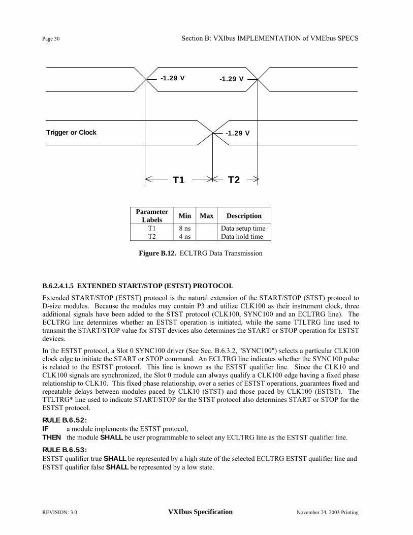
Page 30 Section B: VXIbus IMPLEMENTATION of VMEbus SPECS
REVISION: 3.0 VXIbus Specification November 24, 2003 Printing
Parameter Labels Min Max Description
T1 T2
8 ns 4 ns
Data setup time Data hold time
Figure B.12. ECLTRG Data Transmission
B.6.2.4.1.5 EXTENDED START/STOP (ESTST) PROTOCOL
Extended START/STOP (ESTST) protocol is the natural extension of the START/STOP (STST) protocol to D-size modules. Because the modules may contain P3 and utilize CLK100 as their instrument clock, three additional signals have been added to the STST protocol (CLK100, SYNC100 and an ECLTRG line). The ECLTRG line determines whether an ESTST operation is initiated, while the same TTLTRG line used to transmit the START/STOP value for STST devices also determines the START or STOP operation for ESTST devices.
In the ESTST protocol, a Slot 0 SYNC100 driver (See Sec. B.6.3.2, "SYNC100") selects a particular CLK100 clock edge to initiate the START or STOP command. An ECLTRG line indicates whether the SYNC100 pulse is related to the ESTST protocol. This line is known as the ESTST qualifier line. Since the CLK10 and CLK100 signals are synchronized, the Slot 0 module can always qualify a CLK100 edge having a fixed phase relationship to CLK10. This fixed phase relationship, over a series of ESTST operations, guarantees fixed and repeatable delays between modules paced by CLK10 (STST) and those paced by CLK100 (ESTST). The TTLTRG* line used to indicate START/STOP for the STST protocol also determines START or STOP for the ESTST protocol.
RULE B.6.52: IF a module implements the ESTST protocol, THEN the module SHALL be user programmable to select any ECLTRG line as the ESTST qualifier line.
RULE B.6.53: ESTST qualifier true SHALL be represented by a high state of the selected ECLTRG ESTST qualifier line and ESTST qualifier false SHALL be represented by a low state.
-1.29 V
-1.29 V-1.29 V
Trigger or Clock
T1 T2

Section B: VXIbus IMPLEMENTATION of VMEbus SPECS Page 31
November 24, 2003 Printing VXIbus Specification REVISION: 3.0
RULE B.6.54: A Slot 0 module implementing the ESTST protocol SHALL meet the timing requirements of Figure B.13.
RULE B.6.55: A Slot 0 module implementing the ESTST protocol SHALL meet the timing requirements for the STST protocol.
RULE B.6.56: An ESTST acceptor SHALL accept a SYNC100 setup value for ≥2 ns and held for ≥0.5 ns, an ESTST qualifier value setup for ≥4 ns and held for ≥2 ns and a STST value setup ≥7 ns and held for ≥7 ns with respect to the CLK100 edge. B.6.2.4.1.6 EXTERNAL TRIGGER BUFFERING
RECOMMENDATION B.6.5: Since the ECLTRG asserted sense is opposite the TTLTRG* asserted sense, the ECLTRG signal should be inverted by the Standard External Trigger Buffer. This allows compatibility of external ECLTRG and TLTRG* signals.
OBSERVATION B.6.11: By meeting the loading and driving rules for ECLTRG lines, a module is prohibited from extending these lines external to the chassis without buffering these lines. See Section B.6.2.3.1.6.1, "Standard External Trigger Buffer." B.6.2.5 SUMBUS
The SUMBUS is an analog summing node that is bussed the length of the VXIbus subsystem backplane. It is intended that any module be able to drive or receive from this line. Each module can drive this line using an analog current source driver. Each module may receive information from this bus through a high impedance receiver, such as a high impedance analog buffer amplifier.
RULE B.6.57: The SUMBUS SHALL be terminated to signal ground through 50 ± 1 Ω at each end of the backplane.
RULE B.6.58: A receiver on the SUMBUS SHALL have an equivalent input impedance of ≥10 kΩ in parallel with ≤3 pF.
RULE B.6.59: A SUMBUS output current source SHALL have an equivalent output impedance of >10 kΩ in parallel with ≤4 pF.
RULE B.6.60: A SUMBUS output current source SHALL have ±0.8 V minimum compliance.
RULE B.6.61: A SUMBUS output current source SHALL NOT source more than 40 mA.
RULE B.6.62: The backplane SHALL supply a SUMBUS protection network that clamps the SUMBUS voltage within the range ±3.0 V for all SUMBUS input currents in the range of ±520 mA.

Page 32 Section B: VXIbus IMPLEMENTATION of VMEbus SPECS
REVISION: 3.0 VXIbus Specification November 24, 2003 Printing
Parameter Label Min Max Description
T1 T2 T3 T4 T5 T6
4.0 ns 3.5 ns
13.0 ns 11.0 ns 50.0 ns 15.0 ns
7.5 ns 6.0 ns
SYNC100 setup time SYNC100 hold time ESSTST Qualifier setup time ESTST Qualifier hold time START/STOP setup time START/STOP hold time
Figure B.13. CLK100, SYNC100 and ECLTRG START/STOP Timing
ESTST qualifier
0.8 V0.8 V
2.0 V
-1.29 V
-1.29 V-1.29 V
-1.29 V-1.29 V
START/STOP
SYNC100
CLK100
2.0 V
T5
T1
T3 T4
T6
T2

Section B: VXIbus IMPLEMENTATION of VMEbus SPECS Page 33
November 24, 2003 Printing VXIbus Specification REVISION: 3.0
RULE B.6.63: The SUMBUS protection network SHALL NOT source or sink more than ±1.0 µA nor load with greater than 30 pF for SUMBUS voltages in the range ±1.0 V.
OBSERVATION B.6.12: Low leakage diodes may be required to meet the SUMBUS leakage requirement.
SUGGESTION B.6.1: Because all modules may drive the SUMBUS at the same time, a module designer should consider the total dynamic range of a SUMBUS output current source and be able to adjust the maximum output current accordingly. This will keep the signal within the compliance region.
RULE B.6.64: SUMBUS output current sources and receivers SHALL NOT be located more than 1.0 inch from the P2 DIN SUMBUS pad.
RULE B.6.65: When a module's SUMBUS module output current source is disabled, the module SHALL NOT source more than ±1.0 µA into the SUMBUS.
B.6.2.6 LOCAL BUS
The Local Bus is a daisy chained bus. It is defined by adjacently installed modules. The backplane connects from the LBUSC pins of Slot N to the LBUSA pins of Slot N+1. See Figure B.1. No Local Bus lines are extended beyond Slot 12. Several classes of signal levels are allowed and may be transmitted via this bus. To ensure that modules which produce incompatible levels are not installed in adjacent slots, a keying mechanism has been provided. The Local Bus key provides support for TTL, ECL and analog communication. Each module indicates with the mechanical key on the faceplate which classes of signals it may source or accept nondestructively on each side of its Local Bus. The particular key position for each of the signal classes, as well as sensor-only devices, are specified in the Mechanical Specifications (Section B.7). Sensor-only devices are modules that can non-destructively accept signals of a number of classes, but do not source any signals of their own.
NUMBER CLASS -LIMIT +LIMIT DRIVE LIMIT 1 2 3 4 5 6
TTL ECL ANALOG LOW ANALOG MED ANALOG HIGH RESERVED
-0.5 V -5.46 V -5.5 V
-16.0 V -42.0 V
+5.5 V 0.0 V
+5.5 V +16.0 V +42.0 V
200 mA 50 mA 50 Ω Drive 500 mA 500 mA
TABLE B.3. Logical Classes of LBUS Signals
RULE B.6.66: Modules SHALL NOT drive more than ±42 V onto any LBUS line.
Page 34 Section B: VXIbus IMPLEMENTATION of VMEbus SPECS
REVISION: 3.0 VXIbus Specification November 24, 2003 Printing
RULE B.6.67: Modules SHALL NOT drive more than 500 mA DC current into any LBUS line.
RULE B.6.68: The backplane resistance between any LBUS line and any adjacent pin SHALL be greater than 10.0 MΩ
RULE B.6.69: The di/dt on any LBUS line SHALL NOT exceed ±100 mA/ns.
RECOMMENDATION B.6.6: Multi-Module instrument systems which utilize the Local Bus for intrasystem communications should be built with anchor and expander protocol. An anchor module has no connections on LBUSA lines. It may drive or receive LBUSC lines. An expander module may drive or receive LBUSA or LBUSC lines. Expanders should be placed in adjacent slots (of higher number) to the anchor. This protocol always guarantees compatibility between adjacent module groups without empty slots.
RULE B.6.70: Any module that accesses the LBUS lines SHALL indicate its class on its local bus keys.
RULE B.6.71: A module SHALL NOT exceed the voltage specified for its class under any loading conditions.
OBSERVATION B.6.13: If a module provides a direct connection (an electrical short) between LBUSA lines and LBUSC lines, the keying mechanism should indicate that the module will source on LBUSA and LBUSC any class it accepts on either LBUSA or LBUSC respectively.
RULE B.6.72: A module SHALL NOT indicate on its key the RESERVED signal class.
OBSERVATION B.6.14: The keying mechanism cannot prevent a destructive condition in all situations. It is good practice for a module manufacturer to protect his modules from destruction by any signals within the class it accepts.
RULE B.6.73: The Slot 0 P2 LBUSA key SHALL indicate TTL class.
RULE B.6.74: The Slot 0 P3 LBUSA and LBUSC keys SHALL indicate ECL class.
RULE B.6.75: The mainframe (if it supports VXIbus Subsystem P2) SHALL provide a Slot 0 P2 LBUSC key which indicates TTL class.
RULE B.6.76: The mainframe (if it supports VXIbus Subsystem P3) SHALL provide a Slot 0 P3 LBUSC key which indicates ECL class.
PERMISSION B.6.2: A device which non-destructively senses signals up to ±16 volts, but does not source any signals or provide direct connection between LBUSA and LBUSC, MAY provide a single local bus key tab for ±16 V sensor-only operation.
PERMISSION B.6.3: A device which non-destructively senses all classes of signals up to ±42 volts, but does not source any signals or provide direct connection between LBUSA and LBUSC, MAY provide no local bus key tabs for ±42 V sensor-only operation. Such a device cannot cause a destructive condition.

Section B: VXIbus IMPLEMENTATION of VMEbus SPECS Page 35
November 24, 2003 Printing VXIbus Specification REVISION: 3.0
OBSERVATION B.6.15: A device that does not access the local bus does not provide any local bus keys.
OBSERVATION B.6.16: Size A, B and C modules do not provide P3 local bus keys. B.6.2.7 RSV2-3 (RESERVED)
These pins are reserved.
RULE B.6.77: Modules and backplanes SHALL NOT make any connections to RSV pins. B.6.3 The VXIbus Subsystem P3 Connector
For higher performance instrumentation, the VXIbus also defines the P3 connector. As with P2, alternate pin definitions of P3 may coexist in VXIbus systems, but any one VXIbus subsystem must exist in contiguous slots. Again, Slot 0 plays a unique role in delivering system resources on P3, such as high speed clocking and trigger routing. In particular, VXIbus P3 adds: Additional +5 V, -5.2 V, -2 V, ±24 V and ±12 V power.
100 MHz differential clock which is synchronous with the P2 10 MHz clock.
A synchronizing signal for 100 MHz clock edge selection.
4 additional ECL trigger lines, for a total of 6.
24 additional local bus lines, for a total of 36.
"Star Trigger" lines for precision module to module timing. B.6.3.1 CLK100
CLK100 is a 100 MHz system clock. It is sourced from Slot 0 and distributed to slots 1-12 on P3. The Slot 0 CLK100 output is differential ECL. It is buffered on the backplane and distributed to each module slot as a single source, single destination differential ECL signal in a manner similar to CLK10. The distribution delays are matched to provide a tight timing relationship between modules. The backplane buffering provides a high level of inter-module isolation. RULE B.6.78: The CLK100 frequency sourced from Slot 0 SHALL be 100 MHz. Its accuracy SHALL be equal to or better than ±100 ppm (0.01%), over its specified operating temperature and time.
OBSERVATION B.6.17: A Slot 0 module may generate CLK100 internally or it may derive CLK100 from an external frequency source.
RULE B.6.79: CLK100 duty cycle SHALL be 50% ±20% when measured at the 50% transition level.
RULE B.6.80: IF CLK100 is switched between different clock sources, THEN the minimum clock width, high or low, SHALL NOT be less than 2.5 ns or more than 1.0 ms during switching. The minimum time between two successive transitions of the same polarity SHALL NOT be less than 9.5 ns.

Page 36 Section B: VXIbus IMPLEMENTATION of VMEbus SPECS
REVISION: 3.0 VXIbus Specification November 24, 2003 Printing
PIN
NUMBER
ROW a SIGNAL
MNEMONIC
ROW b SIGNAL
MNEMONIC
ROW c SIGNAL
MNEMONIC
PIN
NUMBER
1 2 3 4 5 6 7 8 9
10 11 12 13 14 15 16 17 18 19 20 21 22 23 24 25 26 27 28 29 30 31 32
ECLTRG2 GND
ECLTRG3 -2 V
ECLTRG4 GND
ECLTRG5 -2 V
LBUSA12 LBUSA13 LBUSA14 LBUSA16 LBUSA17 LBUSA18 LBUSA20 LBUSA21 LBUSA22 LBUSA24 LBUSA25 LBUSA26 LBUSA28 LBUSA29 LBUSA30 LBUSA32 LBUSA33 LBUSA34
GND STARX+ STARX-
GND CLK100+ CLK100-
+24 V -24 V GND RSV5 -5.2 V RSV7 +5 V GND +5 V
LBUSC15 LBUSA15
GND LBUSC19 LBUSA19
+5 V LBUSC23 LUBSA23
-2 V LBUSC27 LBUSA27
GND LBUSC31 LBUSA31
+5 V LBUSC35 LBUSA35
GND -5.2 V GND -5.2 V -2 V GND
+12 V -12 V RSV4 +5 V RSV6 GND -5.2 V GND
LBUSC12 LBUSC13 LBUSC14 LBUSC16 LBUSC17 LBUSC18 LBUSC20 LBUSC21 LBUSC22 LBUSC24 LBUSC25 LBUSC26 LBUSC28 LBUSC29 LBUSC30 LBUSC32 LBUSC33 LBUSC34
GND STARY+ STARY-
-5.2 V SYNC100+ SYNC100-
1 2 3 4 5 6 7 8 9
10 11 12 13 14 15 16 17 18 19 20 21 22 23 24 25 26 27 28 29 30 31 32
TABLE B.4. P3 Pin Definitions
RULE B.6.81: CLK100 SHALL be synchronous to CLK10.
OBSERVATION B.6.18: The absolute timing relationship between CLK10 and CLK100 is not specified. This relationship may be produced by deriving CLK10 from CLK100 or deriving CLK100 from CLK10.

Section B: VXIbus IMPLEMENTATION of VMEbus SPECS Page 37
November 24, 2003 Printing VXIbus Specification REVISION: 3.0
PIN
NUMBER
ROW a SIGNAL
MNEMONIC
ROWb SIGNAL
MNEMONIC
ROWc SIGNAL
MNEMONIC
PIN
NUMBER
1 2 3 4 5 6 7 8 9
10 11 12 13 14 15 16 17 18 19 20 21 22 23 24 25 26 27 28 29 30 31 32
ECLTRG2 GND
ECLTRG3 -2 V
ECLTRG4 GND
ECLTRG5 -2 V
STARY12+ STARY12- STARY12+ STARY11+ STARY11- STARY11+ STARY10+ STARY10- STARY10+ STARY09+ STARY09- STARY09+ STARY08+ STARY08- STARY08+ STARY07+ STARY07- STARY07+
GND STARY+ STARY-
GND CLK100+ CLK 100-
+24 V -24 V GND RSV5 -5.2 V RSV7 +5 V GND +5 V
STARY01- STARY12-
GND STARY02- STARY11-
+5 V STARY03- STARY10-
-2 V STARY04- STARY09-
GND STARY05- STARY08-
+5 V STARY06- STARY07-
GND -5.2 V GND -5.2 V -2 V GND
+12 V -12 V RSV4 +5 V RSV6 GND -5.2 V GND
STARX01+ STARX01- STARX01+ STARX02+ STARX02- STARX02+ STARX03+ STARX03- STARX03+ STARX04+ STARX04- STARX04+ STARX05+ STARX05- STARX05+ STARX06+ STARX06- STARX06+
GND STARY+ STARY-
-5.2 V SYNC100+ SYNC100-
1 2 3 4 5 6 7 8 9
10 11 12 13 14 15 16 17 18 19 20 21 22 23 24 25 26 27 28 29 30 31 32
TABLE B.5. P3 Slot 0 Pin Definitions
RULE B.6.82: The CLK100 and SYNC100 backplane distribution network SHALL NOT insert more than 2.0 ns timing skew between CLK100 and SYNC100 at any slot.
OBSERVATION B.6.19: If a 10H101 distribution buffer is used for CLK100 or SYNC100, the trace lengths should be matched within 1 ns (approximately 15 cm (6 inches)).

Page 38 Section B: VXIbus IMPLEMENTATION of VMEbus SPECS
REVISION: 3.0 VXIbus Specification November 24, 2003 Printing
RULE B.6.83: Each slot's CLK100 SHALL be differentially driven by a unique backplane buffer output.
RULE B.6.84: CLK100 SHALL be differentially driven onto the CLK100+ and CLK100- pins by the module in Slot 0.
RULE B.6.85: The backplane CLK100 distribution traces SHALL be designed for 50 Ω
RULE B.6.86: The CLK100 backplane distribution network SHALL NOT insert more than 2.0 ns timing skew between CLK100 signals at any two slots.
RULE B.6.87: The absolute delay of CLK100 from Slot 0 to any module SHALL NOT exceed 8 ns.
RULE B.6.88: IF a module accesses the CLK100 signals THEN it SHALL provide 50 Ω termination on CLK100+ and CLK100-, with no more than two equivalent ECL loads. B.6.3.2 SYNC100
The synchronization signal SYNC100, is used to synchronize multiple devices with respect to a given rising edge of CLK100. This provides very tight time coordination between modules. The SYNC100 signal is distributed from Slot 0 to slots 1-12, with individual backplane buffers for each slot. The SYNC100 signal can be compared to the GPIB Group Execute Trigger command in function, but with greatly improved time coordination. As the Slot 0 module drives the SYNC100 and CLK100 signals, it may also be programmed to drive one or more ECLTRG lines in order to qualify the SYNC100 action. An example of this protocol is the ESTST protocol described under ECLTRG Trigger Protocols.
A Slot 0 module implementing the SYNC100 function will provide an arbiter to synchronize external events to CLK100 and meet the guaranteed setup and hold times for the SYNC100 signal. This guarantees that all affected modules will trigger on the same CLK100 clock edge. SYNC100 is a nominally 10 ns pulse and may be initiated by any type of external or internal event: an external BNC trigger, a software register write, the state of any of the TTLTRG*, ECLTRG, LBUS or STAR lines or any other signal synchronized by the Slot 0 arbiter. Refer to the timing diagram on Figure B.13.
OBSERVATION B.6.20: SYNC100 delay matching relative to CLK100 is called out under CLK100 matching rules.
RECOMMENDATION B.6.7: Slot 0 modules SHALL provide ≥4.0 ns of setup time from SYNC100 to the rising edge of CLK100.
RULE B.6.89: Slot 0 modules SHALL provide ≥3.5 ns of hold time from rising edge of CLK100 to SYNC100.
RECOMMENDATION B.6.8: Slot 0 modules which provide SYNC100 support should be designed such that the SYNC100 recycle rate is ≤50 ns.
RULE B.6.90: Each module slot SYNC100 SHALL be driven by a unique backplane buffer output.
Section B: VXIbus IMPLEMENTATION of VMEbus SPECS Page 39
November 24, 2003 Printing VXIbus Specification REVISION: 3.0
RULE B.6.91: SYNC100 SHALL be distributed differentially from Slot 0.
RULE B.6.92: The backplane SYNC100 distribution traces SHALL be designed for 50 Ω.
RULE B.6.93: The SYNC100 backplane distribution network SHALL NOT insert more than 2.0 ns timing skew between SYNC100 signals at any two slots.
RULE B.6.94: IF a module accesses the SYNC100 signals THEN it SHALL provide 50 Ω termination on SYNC100+ and SYNC100-, with no more than two equivalent ECL loads. B.6.3.3 STARX and STARY
STARX and STARY provide inter-module asynchronous communication. Two STAR lines are connected between each module slot and Slot 0. Slot 0 may provide a cross matrix switch which can programmably route signals between any two STARX or STARY lines. It may also broadcast a signal received on one STAR line to a group of STAR lines. The STAR lines are bidirectional, providing additional flexibility.
RULE B.6.95: The STARX and STARY backplane distribution network SHALL NOT insert more than 2.0 ns timing skew between any two STAR signals.
RULE B.6.96: STARX and STARY SHALL be driven differentially.
RULE B.6.97: The backplane STAR distribution traces SHALL be designed for 50 Ω.
RULE B.6.98: IF a module accesses the STAR signals THEN it SHALL provide 50 Ω termination on STAR+ and STAR-, with no more than a single equivalent ECL driver load and a single equivalent ECL receiver load.
RULE B.6.99: Modules which can both drive and receive STARX or STARY SHALL use bidirectional ECL drivers, e.g. 10H123. When the module is programmed to receive, the STAR+ and STAR- drivers SHALL be forced into the high impedance state (Vol ≤ -2.0 V)
RULE B.6.100: A D-size Slot 0 module SHALL provide a default differential signal to all STARX and STARY lines which are not being driven by another module.
PERMISSION B.6.4: If a Slot 0 module does not support STAR bus routing, it may meet the above rule by connecting a 50 Ω resistor between STAR+ lines and ground.

Page 40 Section B: VXIbus IMPLEMENTATION of VMEbus SPECS
REVISION: 3.0 VXIbus Specification November 24, 2003 Printing
RULE B.6.101: The absolute delay of any STAR line between Slot 0 and any module SHALL NOT exceed 5 ns.
RULE B.6.102: The backplane SHALL NOT connect to the STARX+, STARX-, STARY+ and STARY- pins of the Slot 0 backplane connector.
PERMISSION B.6.5: The Slot 0 module MAY access the STARX+, STARX-, STARY+ and STARY- pins.
OBSERVATION B.6.21: Allowing all modules, including Slot 0, to access the STAR lines allows construction of modules that may operate in any slot position, including Slot 0. B.6.3.4 ECLTRG2-5
These lines are functionally the same as the ECLTRG0-1 lines on P2 described in Section B.6.2.4, "ECLTRG0-1" and meet the same rules. B.6.3.5 LBUS12-35
These lines are functionally the same as the LBUS00-11 lines on P2 described in Section B.6.2.6, "Local Bus" and meet the same rules. B.6.3.6 RSV4-7
These lines are functionally the same as the RSV2-3 lines on P2 described in Section B.6.2.7, "RSV2-3" and meet the same rules. B.6.4 Backplane
The backplane is the common signal and power distribution network for all modules. As such, it must be very well designed so as not to introduce noise into the system.
OBSERVATION B.6.22: Noise should be minimized on the ECLTRG Lines, Clock lines and SUMBUS lines. It is desirable to maintain time jitter to ≤25 ps. This requires that noise be limited to ±9 mV, assuming an ECL slew rate of 2.75 V/ns.
RULE B.6.103: All backplane ECL transmission paths SHALL be designed for 50 Ω nominal characteristic impedance.
OBSERVATION B.6.23: When TTL lines share a layer of the backplane with 50 Ω ECL transmission lines, the TTL signal characteristic impedance may also be near 50 Ω. This should provide satisfactory operation (See the VME64 specification, Observation 6.13).
SUGGESTION B.6.2: See the MECL System Design Handbook, Motorola, for more backplane and microstrip design information.

Section B: VXIbus IMPLEMENTATION of VMEbus SPECS Page 41
November 24, 2003 Printing VXIbus Specification REVISION: 3.0
B.6.4.1 ECL SIGNAL LEVELS
The signal levels present on the backplane ECL lines are summarized in Table B.6.
Symbol VOH VOL VBB
Parameter Output logic level “1” (HIGH) Output logic level “0” (LOW) Logic Switching Threshold
Minimum -0.980 -1.950
Typical -0.9
-1.75 -1.29
Maximum -0.735 -1.630
Units Volts Volts Volts
TABLE B.6. Backplane ECL signal levels

Page 42 Section B: VXIbus IMPLEMENTATION of VMEbus SPECS
REVISION: 3.0 VXIbus Specification November 24, 2003 Printing
B.7 MECHANICAL SPECIFICATIONS B.7.1 Introduction
Information is provided in this chapter to ensure that VXIbus modules, backplanes, mainframes and associated mechanical accessories are dimensionally compatible.
The mechanical dimensions given in this chapter are based on ANSI/IEEE 1101 and IEC publications 297-3 and 603-2. The electrical characteristics for VXIbus connectors, as specified here, supersede publication 603-2 where they differ.
Figure B.14 is a front view of a typical VXIbus mainframe. In the mainframe shown, modules are inserted into the mainframe from the front, in a vertical plane, with the component face of the module board on the right. B.7.2 Module Specifications B.7.2.1 VXIbus BOARDS and MODULES
RULE B.7.1: VXIbus modules SHALL fit into one of four size classifications:
1. Single height module typically containing a board with dimensions 100 mm (3.937 in) high x 160 mm (6.299 in) deep will be referred to as a "Size A" module.
2. Double height module typically containing a board with dimensions 233.35 mm (9.187 in) high x 160 mm (6.299 in) deep will be referred to as a "Size B" module.
3. Double height module typically containing a board with dimensions 233.35 mm (9.187 in) high x 340 mm (13.386 in) deep will be referred to as a "Size C" module.
4. Triple height module typically containing a board with dimensions 366.7 mm (14.437 in) high x 340 mm (13.386 in) deep will be referred to as a "Size D" module.
RULE B.7.2: Size A and size B boards and board assemblies SHALL be designed according to the dimensions given in the VME64 specification.
OBSERVATION B.7.1: Size A and size B boards and board assemblies are designed for a mainframe with 20.32 mm (0.8 in) spacing between slots.
RULE B.7.3: Size C and size D modules SHALL be contained within the envelope specified in Figures B.17, B.18 and B.21.
RULE B.7.4: Size C and size D modules SHALL be designed for a mainframe with 30.48 mm (1.2 in) spacing between slots.
OBSERVATION B.7.2: Typical size C and size D modules will contain a board as shown in Figures B.15 and B.16.

Section B: VXIbus IMPLEMENTATION of VMEbus SPECS Page 43
November 24, 2003 Printing VXIbus Specification REVISION: 3.0
RULE B.7.5: Modules SHALL provide the board edge feature as specified in Figure B.21 to allow proper insertion into a mainframe. This feature SHALL be 1.6 ± 0.2 mm (0.063 ±0.008 in) thick.
RECOMMENDATION B.7.1: Design C and D modules around a board as specified in Figures B.15 and B.16. This will ensure proper position of connectors, front panel, board edge, etc. B.7.2.1.1 Module Connectors
Size A modules have only one backplane connector, called the P1 connector. Size B and C modules have either one or two backplane connectors, called the P1 and P2 connectors. Size D modules have one, two or three connectors, called the P1, P2 and P3 connectors. In all modules, the P1 connector is mandatory, P2 and P3 are optional.
RULE B.7.6: P1, P2 and P3 connectors SHALL meet or exceed the mechanical specifications of DIN Standard 41612 for Class II, Style C, 3 row, 96-pin connectors.
OBSERVATION B.7.3: DIN Standard 41612 Class II connectors have a minimum mechanical endurance of 400 insertion/extraction cycles.
RULE B.7.7: The mounting location of the P1, P2 and P3 connectors SHALL be consistent with the hole patterns specified in Figures B.15 and B.16.
RULE B.7.8: The P1, P2 and P3 connectors SHALL be positioned as shown in Figures B.19 and B.20. B.7.2.1.2 Board Assemblies
The board assembly typically consists of a PC board and connectors, as defined above and electronic components.
RULE B.7.9: Solder fillets, traces, shielding and components on VXIbus boards SHALL NOT be closer than 2.5 mm (0.098 inches) from the top and bottom edges of the board to guarantee clearance between them and the board guides. Figures B.15 and B.16 show these dimensions for size C and D modules. RULE B.7.10: IF a module contains components sensitive to orientation (e.g. mercury switches), THEN that module's specifications and labels SHALL clearly state its limitations. RECOMMENDATION B.7.2: An orientation sensitive module should be designed to be installed vertically with its component side to the right or horizontally with its component side up.

Page 44 Section B: VXIbus IMPLEMENTATION of VMEbus SPECS
REVISION: 3.0 VXIbus Specification November 24, 2003 Printing
B.7.2.1.3 Module Width
PERMISSION B.7.1: Size C or D modules which require more than the standard spacing MAY be designed to occupy more than one slot, adding an integer multiple of 30.48 mm (1.2 in) to the module width.
OBSERVATION B.7.4: Component height, lead length, shield positions, etc. of the typical module are shown in Figure B.18.
PERMISSION B.7.2: Module shields as shown in Figure B.17 and Figure B.18 MAY be omitted or their positions changed, but must remain within the defined envelope.
RECOMMENDATION B.7.3: Include module shields to improve electromagnetic compatibility (EMC), ease of handling, etc. B.7.2.1.4 Board Warpage, Lead Length, Shield Height and Component Height
RULE B.7.11: All A and B-size board assemblies SHALL meet the requirements of Section 7.2.6 of the VME64 specification
RULE B.7.12: For shielded C and D-size modules, the outer surface of the solder-side shield, including warpage, SHALL be greater than or equal to 1.57 mm (0.062 inch) from the intermodule separation plane when installed. The outer surface of the component-side shield, including warpage, SHALL be greater than or equal to 0.15 mm (0.006 inch) from the intermodule separation plane when installed. Refer to Figure B.18.
RECOMMENDATION B.7.4: To account for warpage, the nominal solder-side shield should be greater than 2.07 mm (0.082 inch) from the intermodule separation plane. The nominal component-side shield should be greater than 0.65mm (0.026 inch) from the intermodule separation plane. Refer to Figure B.18.
RULE B.7.13: For unshielded C and D-size modules, leads and solder-side components, including warpage, SHALL be greater than or equal to 3.96mm (0.156 inch) from the intermodule separation plane when installed. Components, including warpage, SHALL be greater than or equal to 2.54 mm (0.100 inch) from the intermodule separation plane when installed. Refer to Figure B.18. B.7.2.2 FRONT PANEL
This section provides the mechanical specifications for the double and triple height module front panels and associated hardware. Figure B.22 shows a double height, single width (C-size) front panel. Figure B.23 shows a triple height, single width (D-size) front panel.
RULE B.7.14: All modules SHALL include a front panel.
RULE B.7.15: Each module, regardless of size, SHALL have a front panel conforming to the size of the mainframe it is used in.

Section B: VXIbus IMPLEMENTATION of VMEbus SPECS Page 45
November 24, 2003 Printing VXIbus Specification REVISION: 3.0
PERMISSION B.7.3: Additional hardware MAY be utilized to fill a front panel gap when inserting a small module into a larger mainframe.
RULE B.7.16: Front panel screws SHALL be provided to secure the top and bottom of the panel to the mainframe and their screw threads SHALL be M2.5 x 0.45 pitch. See Figure B.22.
RULE B.7.17: Front panels SHALL make contact with chassis ground in the area surrounding the retention screws as shown in Figure B.22 and Figure B.23. This surface SHALL be conductive, smooth and free of all protrusions. B.7.2.2.1 Front Panel Mounting
RULE B.7.18: All modules SHALL comply with the test dimension shown in Figure B.26 and Figure B.27. This dimension is from the rear face of the front panel to the rear face of the backplane connector. B.7.2.2.2 Front Panel Dimensions
RULE B.7.19 Single width C- and D-size front panels SHALL be designed to the dimensions shown in Figure B.22 and Figure B.23 respectively.
RULE B.7.20: IF a C- or D-size module occupies more than one slot THEN the width of the front panel SHALL be 30.18 mm (1.188 inch) plus an integral multiple (N) of 30.48 mm (1.200 inch), where N is the number of slots that the module occupies minus one.
RULE B.7.21: IF local bus lockout keys are required on a module, THEN the front panel SHALL be notched as shown in Figure B.22 and Figure B.23.
SUGGESTION B.7.1: Include the lockout key notch on all front panels. This will simplify removal of a module when the adjacent module is keyed. B.7.2.2.3 Filler Panels
RULE B.7.22: Filler panels SHALL be used in any empty slots.
OBSERVATION B.7.5: Filler panels are often required by safety regulations and may be necessary for cooling and EMC performance.
RULE B.7.23: C- and D-size filler panels SHALL conform to dimensions given in Figure B.24 and Figure B.25 respectively.
RULE B.7.24: A- and B-size filler panels SHALL conform to Section 7.3.4 of the VME64 Specification.
Page 46 Section B: VXIbus IMPLEMENTATION of VMEbus SPECS
REVISION: 3.0 VXIbus Specification November 24, 2003 Printing
B.7.2.2.4 Module Injectors/Ejectors
Insertion and extraction forces of the module relative to the mainframe may be very high. These forces are greatest for D-size modules that use all three backplane connectors.
RECOMMENDATION B.7.5: Modules using two or more of the 96-pin DIN Standard 41612 Class II connectors should provide an injector/ejector system.
OBSERVATION B.7.6: The insertion force for three 96-pin DIN Standard 41612 Class II connectors can be as high as 270 N (60.69 lbf).
PERMISSION B.7.4: An injector and /or ejector system MAY be provided on any module size.
RULE B.7.25: Modules equipped with ejectors or injectors SHALL NOT interfere with mainframes designed to the VXIbus or VME64 specification. See Figure B.37.
OBSERVATION B.7.7: Refer to Section B.7.3.3, "Injection/Ejection", for more information B.7.2.2.5 Front Panel Interface
RULE B.7.26: External wiring to a module, if any, SHALL exit the module only through the front panel area.
OBSERVATION B.7.8: External wiring is defined as any connectors, cables, etc. that carry signals or interfaces out of the mainframe in which the module is installed. The above rule does not exclude module-to-module wiring.
RULE B.7.27: Connector and front panel interfaces SHALL NOT leave significant gaps in the front panel or disrupt proper airflow within the system.
OBSERVATION B.7.9: Although the terms "significant gaps" and "proper air flow" can be rather broadly interpreted, it is intended that a manufacturer be very cautious about the front panel components chosen. B.7.2.2.6 Front Panel Handles
RULE B.7.28: Handles SHALL NOT interfere with the local bus lockout keys of adjacent modules.
SUGGESTION B.7.2: Handle width and position should comply with the dimensions shown in Figure B.22 and Figure B.23. This will avoid interference with local bus lockout keys.
OBSERVATION B.7.10: Injection and ejection constraints may require the use of a handle with dimensions different than those in Figure B.22 and Figure B.23.
Section B: VXIbus IMPLEMENTATION of VMEbus SPECS Page 47
November 24, 2003 Printing VXIbus Specification REVISION: 3.0
B.7.2.3 MODULE SHIELDING
Shields are often included in modules to improve EMC performance, ease of handling, etc. Refer to Figure B.17 and Figure B.18.
PERMISSION B.7.5: Module shields MAY be tied to chassis ground or circuit ground.
RULE B.7.29: C-size and D-size modules SHALL provide room for the optional mainframe chassis shield as shown in Figure B.17 and Figure B.18.
OBSERVATION B.7.11: The envelope as defined in Figure B.17 ensures that module shields do not contact adjacent modules.
PERMISSION B.7.6: A grounding shield MAY be provided around each 96-pin connector as shown in Figure B.34. This will be referred to as the connector shield.
OBSERVATION B.7.12: Connector shield contacts may or may not be removable. However, removable contacts may be advisable for some modules. The module manufacturer should evaluate the applicability of removable contacts for each module.
PERMISSION B.7.7: A module MAY make electrical contact with a compatible adjacent module at any point in the area near the front panel as specified in Figure B.17. This contact may be implemented by means of gasketing, clips, etc.
RULE B.7.30: IF gasketing is installed for contact with a compatible adjacent module, THEN it SHALL be installed on the solder side (as defined in Figure B.17) only and it SHALL be compressible to fit within the intermodule separation plane.
RECOMMENDATION B.7.6: Gasketing installed for contact with a compatible adjacent module should be removable. This will allow installation adjacent to unshielded or otherwise incompatible modules.
RECOMMENDATION B.7.7: The areas specified in Figure B.17 for contact with adjacent modules should be chassis ground and conductive. B.7.2.4 MODULE COOLING
Test set-up and procedures for establishing module cooling requirements are detailed in VXI-8, Rev 2.0, "Cooling Characterization Methodology Specification"[2]. Module cooling requirement specifications include an operating point. The operating point includes three pieces of information:
• The maximum recommended temperature rise of cooling air as it flows through the module (typically 10°C).
• The airflow required to maintain the recommended temperature rise (in liters/second). • The pressure drop that is created across the module by the required airflow (in mm H2O).

Page 48 Section B: VXIbus IMPLEMENTATION of VMEbus SPECS
REVISION: 3.0 VXIbus Specification November 24, 2003 Printing
RULE B.7.31: Cooling air SHALL flow as shown in Figure B.29, FigureB.30 and Figure B.38. Airflow direction is from P3 to P1.
RULE B.7.32: Cooling requirements SHALL be established for all modules and included in product specifications.
RULE B.7.33: Module cooling requirement specifications SHALL be in compliance with Specification VXI-8. The specifications SHALL include the maximum ambient operating temperature and the operating point. (Example: 55°C ambient maximum operating temperature. For 10°C internal rise, 0.5 mm H2O @ 1.5 liters/second)
B.7.2.5 MODULE POWER
RECOMMENDATION B.7.8: Attach an abbreviated version of the power supply voltage and current requirements to the module. This will facilitate system integration. B.7.2.6 MODULE KEYING
Lockout keys are provided to serve as an impediment to local bus incompatibilities.
RULE B.7.34: IF modules access a local bus, THEN lockout keys SHALL be provided, consistent with the particular bus accessed. The lockout keys SHALL conform to the specifications in Figure B.28.
RULE B.7.35: IF lockout keys are required on a module, THEN they SHALL be installed by the manufacturer, consistent with the definition of the product.
OBSERVATION B.7.13: Lockout keys are not intended to provide failsafe protection. Accidental damage may still occur if incompatible modules are forced next to each other on the local bus. B.7.2.7 MODULE ENVIRONMENTAL
RECOMMENDATION B.7.9: Test modules for temperature, humidity, vibration, shock, etc., according to the procedures described in IEC Publication 68. Include the results in product specifications, along with module mass.
OBSERVATION B.7.14: It is a system integrator's responsibility to select modules and mainframes appropriate for the application's environmental requirements.

Section B: VXIbus IMPLEMENTATION of VMEbus SPECS Page 49
November 24, 2003 Printing VXIbus Specification REVISION: 3.0
B.7.3 Mainframe Specifications
RULE B.7.36: VXIbus mainframes SHALL fit into one of four size classifications:
1. A mainframe that provides the J1 backplane and allows the insertion of an A-size module, only, will be referred to as an "A-size" mainframe and conform to the VME64 specifications for subracks.
2. A mainframe that allows the insertion of a B-size module, maximum, will be referred to as a "B-size" mainframe and conform to the VME64 specifications for subracks. The J1 backplane is mandatory, J2 is optional.
3. A mainframe that allows the insertion of a C-size module, maximum, will be referred to as a "C-size" mainframe. The J1 backplane is mandatory, J2 is optional.
4. A mainframe that allows the insertion of a D-size module, maximum, will be referred to as a "D-size" mainframe. The J1 backplane is mandatory, J2 and J3 are optional.
RECOMMENDATION B.7.10: Allowances should be made for the insertion of A-size modules into B-size mainframes, the insertion of A- and B-size modules into C-size mainframes and the insertion of A-, B- and C-size modules into D-size mainframes.
OBSERVATION B.7.15: Additional hardware and removable module guides may be required to allow the insertion of smaller modules into a larger mainframe.
RULE B.7.37 IF the insertion of smaller modules is allowed into a larger mainframe, THEN the mainframe manufacturer SHALL specify a procedure and/or means for the insertion of the smaller modules.
PERMISSION B.7.8: Mechanical and/or electrical means may be used for the adaptation of a smaller module to a larger mainframe.
RULE B.7.38: C- and D-size mainframes SHALL be designed for 30.48 mm (1.2 in) slot spacing, as shown in Figure B.30.
RULE B.7.39: A and B-size mainframes SHALL be designed to 20.32 mm (0.8 inch) spacing.
RULE B.7.40: C- and D-size mainframes SHALL conform to the dimensions and tolerances shown in Figure B.29 and Figure B.30. This ensures that connectors mate properly and that modules will fit in the mainframe without interference.
RULE B.7.41: With the mainframe oriented with the modules vertical, P1 at the top, component side of module boards to the right; Slot 0 SHALL be the left most slot of any VXIbus subsystem.
OBSERVATION B.7.16: This rule does not mandate mainframe orientation; it only establishes the position of Slot 0 relative to mainframe orientation.

Page 50 Section B: VXIbus IMPLEMENTATION of VMEbus SPECS
REVISION: 3.0 VXIbus Specification November 24, 2003 Printing
SUGGESTION B.7.3: IF vertical orientation of the modules is desired, THEN Slot 0 should be at the left. IF horizontal orientation of the modules is desired, THEN Slot 0 should be at the bottom.
RULE B.7.42: Module guides SHALL be made of non-conductive material or be isolated from chassis ground. B.7.3.1 BACKPLANES
RULE B.7.43: Each backplane SHALL be a single monolithic board, within any slot position.
RULE B.7.44: Backplane connectors for C and D-size mainframes SHALL be positioned as shown in Figures B.31 and B.32.
PERMISSION B.7.9: Backplanes MAY deviate from Figure B.31 and Figure B.32 in structure and mounting methods.
OBSERVATION B.7.17: Typical C and D-size backplanes are shown in Figure B.31 and Figure B.32 for reference. Adherence to these drawings will ease the task of mounting and aligning the backplane within the mainframe.
RULE B.7.45: IF components other than connectors are placed on the component side of A-size C or D backplane, THEN they SHALL be placed outside the shaded areas specified in Figure B.33. Non-conductive components SHALL be less than 12.2 mm (0.480 inch) in height. Conductive components SHALL be less than 10.0 mm (0.394 inch) in height.
RECOMMENDATION B.7.11: Mainframes should allow shielding around each 96-pin backplane connector. This shield typically provides a connection between a ground ring on the backplane and a module. See the references to the "connector shield" in Section B.7.2.3, "Module Shielding". Refer also to the above Rule, Figure B.33 and Figure B.34.
RULE B.7.46: Connector shields SHALL comply with Figure B.34.
RULE B.7.47: IF conductive backplane traces are exposed within the ground ring area defined by Figure B.33, THEN the potential of those traces SHALL be circuit ground.
RULE B.7.48: Components SHALL NOT be located near backplane connectors as specified in Figure B.33.
RULE B.7.49: DIN Standard 41612 Class II, Style C, 3 row, 96-pin socket type connectors SHALL be used on all J1, J2 and J3 positions.
RULE B.7.50: The VXIbus J1 bus SHALL have some provision for jumpering the interrupt acknowledge and bus grant daisy-chains when boards are not plugged into a slot.
Section B: VXIbus IMPLEMENTATION of VMEbus SPECS Page 51
November 24, 2003 Printing VXIbus Specification REVISION: 3.0
B.7.3.2 GROUNDING
OBSERVATION B.7.18: Mainframes may connect circuit ground to chassis ground.
RULE B.7.51: All mainframes SHALL provide chassis ground to the module front panels in the area of the front panel mounting screws. The chassis ground contact area is shown in Figure B.22 for C-size modules and in Figure B.23 for D-size modules. B.7.3.3 INJECTION, EJECTION and DETECTION
RULE B.7.52: Mainframes SHALL provide a surface for module extraction as shown in Figure B.37.
RECOMMENDATION B.7.12: Mainframes should provide a surface for module injection, as shown in Figure B.37.
RULE B.7.53: Mainframes SHALL NOT interfere with injector/ejector systems conforming to Figure B.37.
RECOMMENDATION B.7.13: If module detection mechanisms are included in a mainframe, their actuators should be positioned to contact the module front panels on the surface defined in Figure B.22 and B.23.
OBSERVATION B.7.19: Module detection mechanisms can be used to actuate airflow control shutters.
SUGGESTION B.7.4: Make module detection mechanisms removable, in order to allow integration of modules that are incompatible with the detection mechanisms. B.7.3.4 MAINFRAME SHIELDING
PERMISSION B.7.10: Mainframes MAY allow the installation of a chassis potential shield as shown in Figure B.17 and Figure B.18.
RULE B.7.54: IF mainframe chassis shields are provided, THEN they SHALL be removable.
RULE B.7.55: IF the shield potential of a module is not chassis ground or the module is unshielded, THEN any adjacent chassis shield SHALL be insulated.
PERMISSION B.7.11: IF the shield potential of a module is defined as chassis ground, THEN electrical contact between the module and adjacent chassis shields MAY be allowed.
RECOMMENDATION B.7.14: IF a mainframe has provision for chassis shields, THEN both insulated and non-insulated shields should be available.

Page 52 Section B: VXIbus IMPLEMENTATION of VMEbus SPECS
REVISION: 3.0 VXIbus Specification November 24, 2003 Printing
B.7.3.5 MAINFRAME COOLING
Test set-up and procedures for establishing mainframe cooling requirements are detailed in VXI-8, Rev 2.0, "Cooling Characterization Methodology Specification". [2]
RULE B.7.56: IF a mainframe provides cooling air, THEN it SHALL supply the air to each slot in the minimum area specified in Figure B.38.
RULE B.7.57: IF a mainframe provides cooling air, THEN that mainframe SHALL provide room for the exhausted cooling air to exit each slot in the minimum area specified in Figure B.38.
PERMISSION B.7.12: A mainframe MAY provide for additional cooling air entry and exhaust in areas outside those specified in Figure B.38.
RULE B.7.58: Cooling specifications SHALL be established for all mainframes and included in the product specifications.
RULE B.7.59: Mainframe cooling specifications SHALL be in compliance with Specification VXI-8. These specifications SHALL include a minimum performance curve, ∆p (in mm H2O) vs. airflow (in liters/second), a figure of merit for the airflow variation (in %) within a single slot and the conditions under which the measurements were made. See Figure B.39.
PERMISSION B.7.13: Mainframe cooling specifications MAY include a power dissipation specification (in Watts/slot), derived in accordance with VXI-8. B.7.3.6 MAINFRAME POWER
RECOMMENDATION B.7.15: Label the mainframe with an abbreviated version of the power supply specifications. This label should specify available current of the supply voltages and state whether circuit ground is connected to chassis ground. This will facilitate system integration. B.7.3.7 KEYING
RULE B.7.60: Mainframes SHALL provide local bus lockout keys for Slot 0. These keys SHALL allow only TTL compatible modules on P2 and only ECL compatible modules on P3. See Figure B.28.
OBSERVATION B.7.20: Mainframe lockout keys typically consist of a tab or recess to the left of Slot 0. See Figure B.14.

Section B: VXIbus IMPLEMENTATION of VMEbus SPECS Page 53
November 24, 2003 Printing VXIbus Specification REVISION: 3.0
B.7.3.8 MAINFRAME ENVIRONMENTAL
RECOMMENDATION B.7.16: Test mainframes for temperature, humidity, vibration, shock, etc., according to the procedures described in IEC Publication 68. Include the results in product specifications.
SUGGESTION B.7.5: Include specifications for the vibration and shock environment experienced by modules installed in a mainframe during testing of the mainframe. This should include a variety of module weights and slot positions.
OBSERVATION B.7.21: It is a system integrator's responsibility to select modules and mainframes appropriate for the application's environmental requirements.
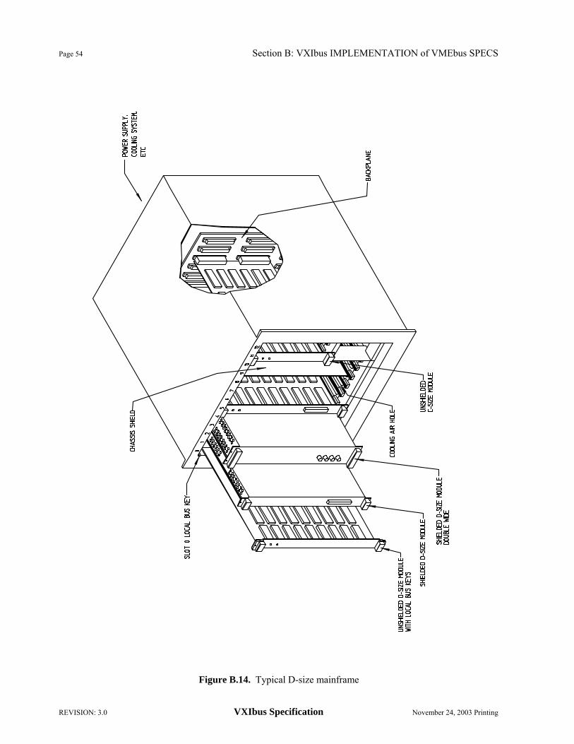
Page 54 Section B: VXIbus IMPLEMENTATION of VMEbus SPECS
REVISION: 3.0 VXIbus Specification November 24, 2003 Printing
Figure B.14. Typical D-size mainframe
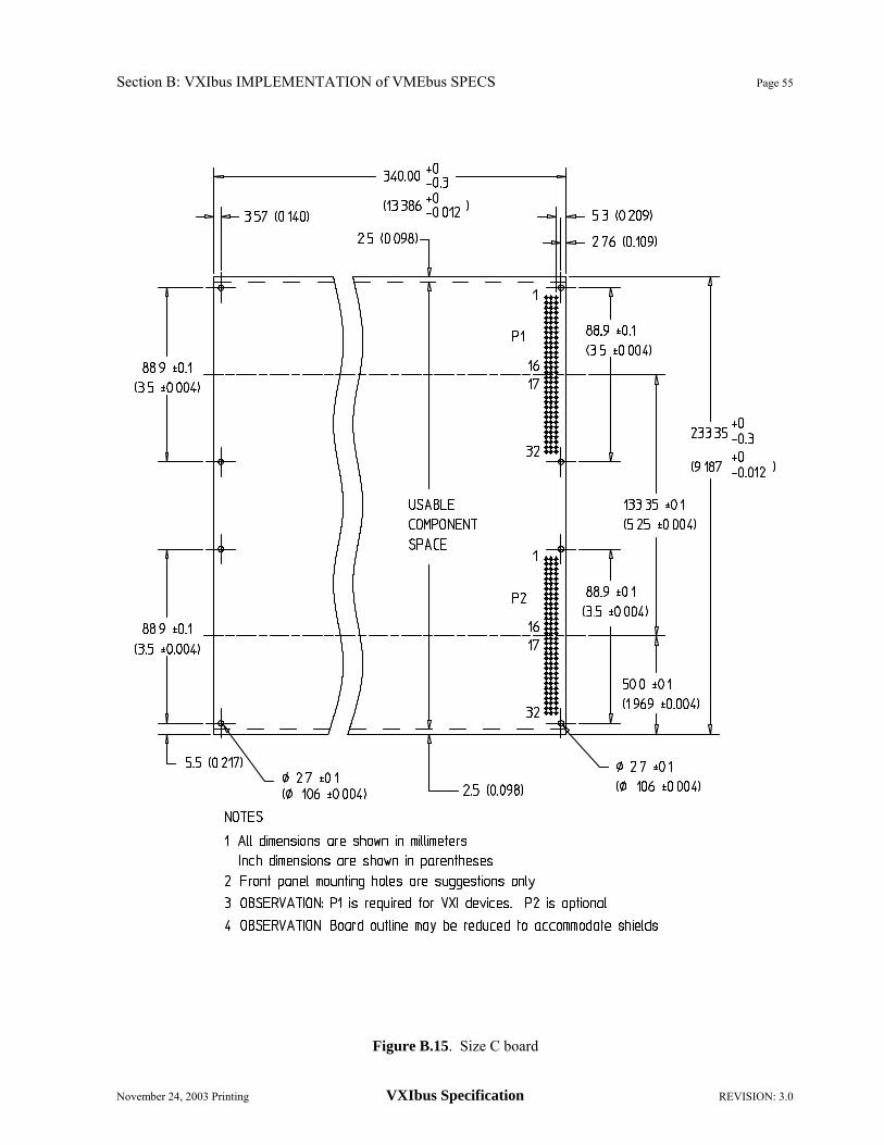
Section B: VXIbus IMPLEMENTATION of VMEbus SPECS Page 55
November 24, 2003 Printing VXIbus Specification REVISION: 3.0
Figure B.15. Size C board
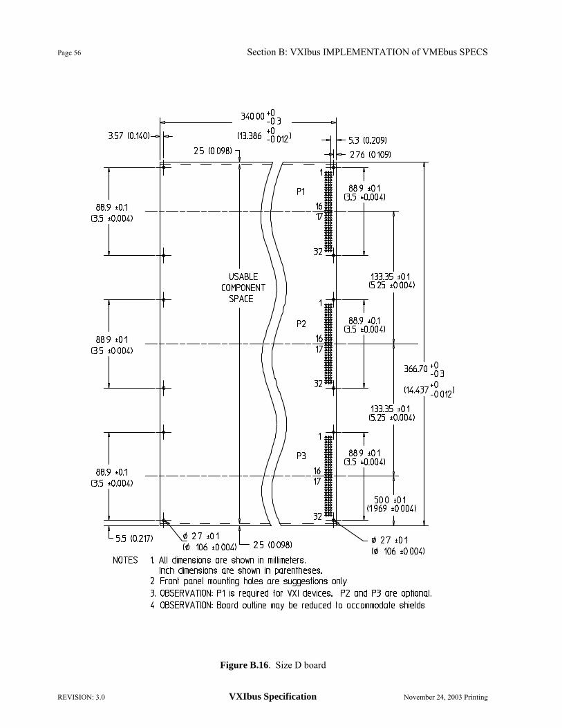
Page 56 Section B: VXIbus IMPLEMENTATION of VMEbus SPECS
REVISION: 3.0 VXIbus Specification November 24, 2003 Printing
Figure B.16. Size D board

Section B: VXIbus IMPLEMENTATION of VMEbus SPECS Page 57
November 24, 2003 Printing VXIbus Specification REVISION: 3.0
Figure B.17. Module envelope, top view

Page 58 Section B: VXIbus IMPLEMENTATION of VMEbus SPECS
REVISION: 3.0 VXIbus Specification November 24, 2003 Printing
Figure B.18. Module envelope, front view

Section B: VXIbus IMPLEMENTATION of VMEbus SPECS Page 59
November 24, 2003 Printing VXIbus Specification REVISION: 3.0
Figure B.19. C-size board assembly connector positions

Page 60 Section B: VXIbus IMPLEMENTATION of VMEbus SPECS
REVISION: 3.0 VXIbus Specification November 24, 2003 Printing
Figure B.20. D-size board assembly connector positions

Section B: VXIbus IMPLEMENTATION of VMEbus SPECS Page 61
November 24, 2003 Printing VXIbus Specification REVISION: 3.0
Figure B.21. Module edge guide feature

Page 62 Section B: VXIbus IMPLEMENTATION of VMEbus SPECS
REVISION: 3.0 VXIbus Specification November 24, 2003 Printing
Figure B.22. C-size Front panel details

Section B: VXIbus IMPLEMENTATION of VMEbus SPECS Page 63
November 24, 2003 Printing VXIbus Specification REVISION: 3.0
Figure B.23. D-size Front panel details

Page 64 Section B: VXIbus IMPLEMENTATION of VMEbus SPECS
REVISION: 3.0 VXIbus Specification November 24, 2003 Printing
Figure B.24. C-size filler panel

Section B: VXIbus IMPLEMENTATION of VMEbus SPECS Page 65
November 24, 2003 Printing VXIbus Specification REVISION: 3.0
Figure B.25. D-size filler panel
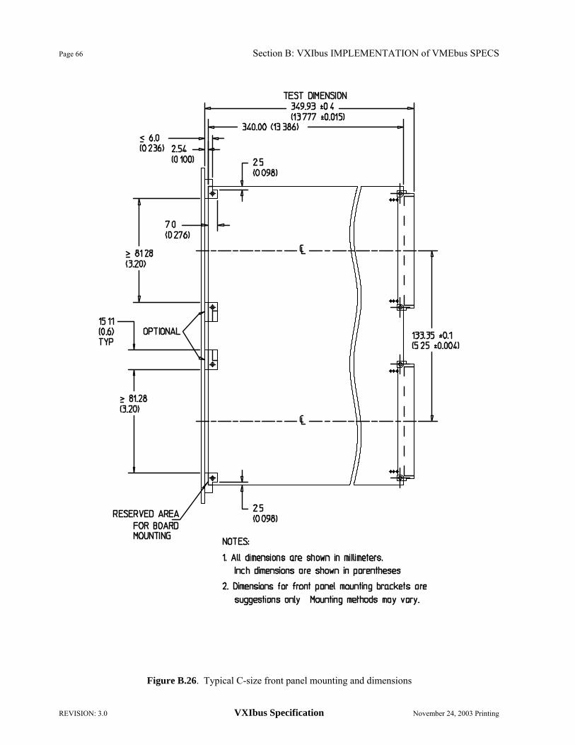
Page 66 Section B: VXIbus IMPLEMENTATION of VMEbus SPECS
REVISION: 3.0 VXIbus Specification November 24, 2003 Printing
Figure B.26. Typical C-size front panel mounting and dimensions

Section B: VXIbus IMPLEMENTATION of VMEbus SPECS Page 67
November 24, 2003 Printing VXIbus Specification REVISION: 3.0
Figure B.27. Typical D-size front panel mounting and dimensions

Page 68 Section B: VXIbus IMPLEMENTATION of VMEbus SPECS
REVISION: 3.0 VXIbus Specification November 24, 2003 Printing
Figure B.28. Local bus lockout key details

Section B: VXIbus IMPLEMENTATION of VMEbus SPECS Page 69
November 24, 2003 Printing VXIbus Specification REVISION: 3.0
Figure B.29. C-size mainframe drawing

Page 70 Section B: VXIbus IMPLEMENTATION of VMEbus SPECS
REVISION: 3.0 VXIbus Specification November 24, 2003 Printing
Figure B.30. D-size mainframe drawing

Section B: VXIbus IMPLEMENTATION of VMEbus SPECS Page 71
November 24, 2003 Printing VXIbus Specification REVISION: 3.0
Figure B.31. C-size backplane drawing
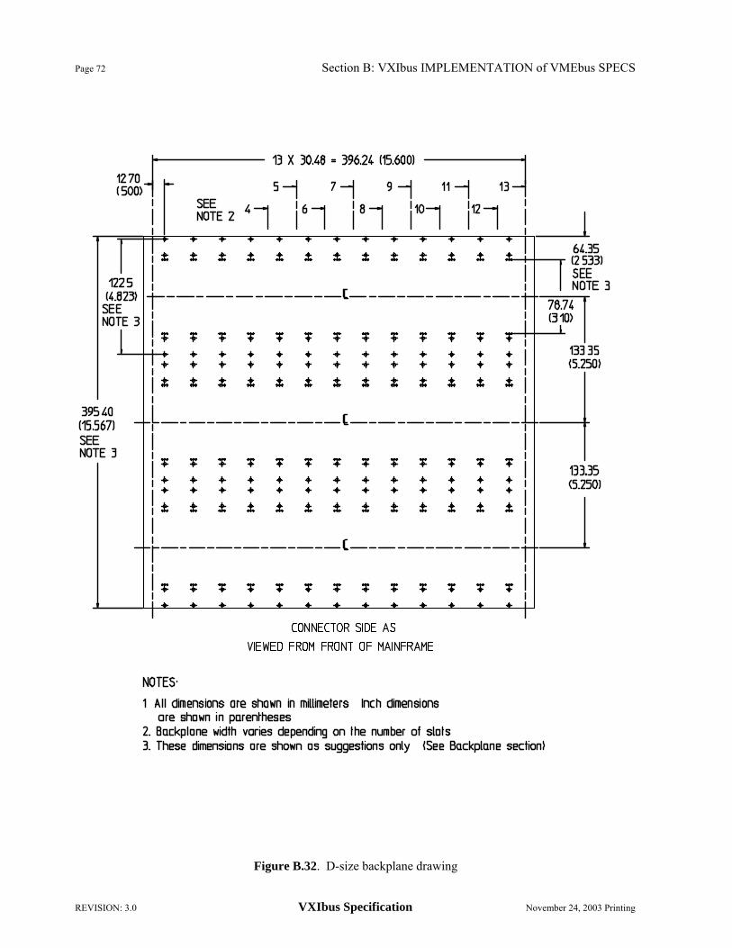
Page 72 Section B: VXIbus IMPLEMENTATION of VMEbus SPECS
REVISION: 3.0 VXIbus Specification November 24, 2003 Printing
Figure B.32. D-size backplane drawing

Section B: VXIbus IMPLEMENTATION of VMEbus SPECS Page 73
November 24, 2003 Printing VXIbus Specification REVISION: 3.0
Figure B.33. Detailed backplane dimensions

Page 74 Section B: VXIbus IMPLEMENTATION of VMEbus SPECS
REVISION: 3.0 VXIbus Specification November 24, 2003 Printing
Figure B.34. Backplane connector shield
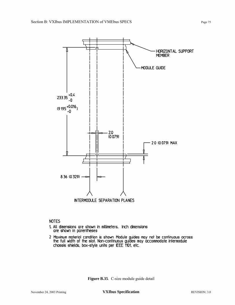
Section B: VXIbus IMPLEMENTATION of VMEbus SPECS Page 75
November 24, 2003 Printing VXIbus Specification REVISION: 3.0
Figure B.35. C-size module guide detail

Page 76 Section B: VXIbus IMPLEMENTATION of VMEbus SPECS
REVISION: 3.0 VXIbus Specification November 24, 2003 Printing
Figure B.36. D-size module guide detail

Section B: VXIbus IMPLEMENTATION of VMEbus SPECS Page 77
November 24, 2003 Printing VXIbus Specification REVISION: 3.0
Figure B.37. Module injection and ejection surfaces

Page 78 Section B: VXIbus IMPLEMENTATION of VMEbus SPECS
REVISION: 3.0 VXIbus Specification November 24, 2003 Printing
Figure B.38. C and D-size module inlet and exhaust areas

Section B: VXIbus IMPLEMENTATION of VMEbus SPECS Page 79
November 24, 2003 Printing VXIbus Specification REVISION: 3.0
Figure B.39. Example of mainframe cooling specification

Page 80 Section B: VXIbus IMPLEMENTATION of VMEbus SPECS
REVISION: 3.0 VXIbus Specification November 24, 2003 Printing
B.8 EMC and SYSTEM POWER B.8.1 Introduction
The VXIbus backplane is governed by the following rules.
RULE B.8.1: VXIbus subsystems SHALL provide power conductors for distribution of +5 V, +5 STDBY, +12 V, -12 V, +24 V, -24 V, -5.2 V and -2 V to all of the power pins specified in the pin assignments. B.8.2 Power Distribution
Power in a VXIbus system is distributed on the backplane as regulated direct current (DC) voltages. The available voltages are:
+5 VDC This is the main power source for most VXIbus systems. All systems require this voltage for bus communications.
+/-12 VDC These are often used for powering analog devices, disc drives and communication interfaces.
+/-24 VDC These are used for powering analog signal sources and to derive other voltage levels (e.g. +/-15 VDC) as needed using on-board regulators.
-5.2 VDC This is used for ECL devices.
-2 VDC This is used for termination of ECL loads.
+5 VDC STDBY This is used to sustain memory, clocks, etc. when the +5 VDC power is lost. B.8.3 Power Pins
RULE B.8.2: The current flow per pin on any connector SHALL comply with Figure 5-7 in the VMEbus specification based on temperature rise considerations in the target system.
OBSERVATION B.8.1 A 1 ampere per pin limit allows the VMEbus rated connector to operate at 55°C ambient. B.8.4 DC Voltage Specifications
RULE B.8.3: Any voltage furnished by the mainframe power supply SHALL comply with the maximum Allowed Variation and maximum allowed DC Load Ripple/Noise in Table B.7, up to the mainframe's maximum rated current (IMP).

Section B: VXIbus IMPLEMENTATION of VMEbus SPECS Page 81
November 24, 2003 Printing VXIbus Specification REVISION: 3.0
VOLTAGE DESCRIPTION ALLOWED VARIATION DC LOAD
RIPPLE/NOISE INDUCED
RIPPLE/NOISE +5 V
+12 V -12 V +24 V -24 V
-5.2 V -2 V
+5 V STDBY
+5 VDC +12 VDC -12 VDC +24 VDC -24 VDC -5.2 VDC -2 VDC +5 VDC standby
+0.25 V/-0.125 V +0.60 V/-0.36 V -0.60 V/+0.36 V +1.20 V/-0.72 V -1.20 V/+0.72 V -0.260 V/-0.156 V -0.10 V/+0.10 V +0.25 V/-0.125 V
50 mV 50 mV 50 mV 150 mV 150 mV 50 mV 50 mV 50 mV
50 mV 50 mV 50 mV 150 mV 150 mV 50 mV 50 mV 50 mV
TABLE B.7. Power Supply Voltage Specifications
DC Load Ripple/Noise is the maximum Periodic And Random Deviations (PARD) generated by the power supply under all DC load conditions up to the Mainframe Peak Current, measured as the peak-to-peak voltage in the DC to 10 MHz bandwidth. This is the VML parameter in Figure B.41 and Figure B.43.
Induced Ripple/Noise is the additional peak-to-peak ripple that may exist on the backplane power supply pins due to injected current from operating modules. This is the VMI parameter in Figure B.41 and Figure B.43.
Mainframe Peak Current (IMP) is the rated DC current of a particular voltage supplied by the mainframe.
Mainframe Dynamic Current (IMD) is the rated dynamic current capacity of a particular voltage supplied by the mainframe for the frequencies from 20 Hz to 1 GHz.
RULE B.8.4: Power Supplies source power to the modules and SHALL NOT be used to sink power other than transient current from protection circuits.
OBSERVATION B.8.2: The non-symmetric variation given in Table B.7 ensures that the DC power remains within the tolerance required by most ICs despite the typical voltage drops that occur in the power distribution network. Placing the power supply sense point near the power input point prevents boards near the power input point from receiving too high a voltage.
RULE B.8.5: All voltages which are supplied by a mainframe SHALL tolerate peak to peak current variations of IMP from DC to 20 Hz without generating peak to peak voltage variations in the DC to 20 Hz frequency range exceeding the Induced Ripple/Noise limit of Table B.7.
RULE B.8.6: All voltages which are supplied by a mainframe SHALL tolerate peak to peak current variations as specified by the Max. Rated Mainframe Dynamic Current (IMD) in Figure B.40 without generating total (Induced and Load Ripple/Noise) peak to peak voltage variations exceeding the limits specified in Figure B.41.For the test method see Section B.8.7.2 "Induced Ripple Noise Test of Mainframes". IMD is the rated dynamic current of the mainframe supply. VMI is the peak-to-peak Induced Ripple/Noise specified in Table B.3. VML is the peak-to-peak DC Load Ripple/Noise specified in Table B.7. Slots is the number of VXIbus module slots in the mainframe.

Page 82 Section B: VXIbus IMPLEMENTATION of VMEbus SPECS
REVISION: 3.0 VXIbus Specification November 24, 2003 Printing
Figure B.40. Mainframe Load Current
Figure B.41. Mainframe Induced and Load Ripple/Noise Voltage Limits
OBSERVATION B.8.3: The rated Mainframe Dynamic Current (IMD) is chosen by the manufacturer to ensure compliance with the above Induced Ripple/Noise specification.
------ Induced and DC Load Ripple/Noise (Table B.7)
VMI + VML
4
VMI + VML
2
VMI + VML
10 MHz20 kHz 20 kHz 20 MHz 1 GHz20 Hz
1 GHz 10 kHz 20 Hz
Slots X 10-3
IMD
IMP
DC
Max. Rated Mainframe Dynamic Output Current
Max. Rated Mainframe Peak Output Current
20 dB / decade
IMD X 107 Hz Slots
20 dB/decade
20 dB/decade

Section B: VXIbus IMPLEMENTATION of VMEbus SPECS Page 83
November 24, 2003 Printing VXIbus Specification REVISION: 3.0
B.8.5 Power Management
The power compatibility of mainframes and modules is accomplished by documenting the mainframe output power (both peak and dynamic) and module input power (both peak and dynamic). Mainframe power supplies will identify all voltage and current capabilities which are present in the mainframe. Modules will identify all voltage and input current requirements for proper operation. This documentation of the power requirements will allow the system integrator to verify compatibility between mainframe output power capability and module supply requirements.
Successful integration of a VXIbus instrument system depends on the power compatibility of mainframes and modules. The individual dynamic currents of modules will add together to form complex dynamic currents that the mainframe must tolerate in order to maintain its ripple specifications. The VXIbus rules establish a minimum level of mainframe and module documentation with which the manufacturer must comply.
Peak Module Current (IPm) is the maximum rated instantaneous current measured in the DC to 10 MHz bandwidth which is drawn by a module for a particular supply voltage during normal operation.
Dynamic Module Current (IDm) is the maximum rated dynamic current required by the module. IDm is chosen by the manufacturer so that the module meets the conducted emission test from 20 Hz to 1 GHz.
RULE B.8.7: Mainframe Peak Current (IMP) and Mainframe Dynamic Current (IMD) SHALL be documented by the mainframe manufacturer for every voltage, even if not supported.
RECOMMENDATION B.8.1: Mainframe should be marked with current rating of all voltages listed even if not supplied. Example: +5 V STDBY = 0.0 A Peak, 0.0 A Dynamic (if not supported).
RULE B.8.8: Peak Module Current (IPm) and Dynamic Module Current (IDm) SHALL be documented by the module manufacturer for all power supply voltages used.
RECOMMENDATION B.8.2: Modules should be marked with input current specifications for all voltages used.
OBSERVATION B.8.4: The module peak current is measured with a 10 MHz bandwidth instrument to ensure that contributions from all potentially significant frequency components are included. For proper operation, the peak current capacity of the mainframe (IMP) is required to exceed the sum of the Peak Module Currents (IPm) for each supply used. If the dynamic current capacity of the mainframe (IMD) exceeds the sum of the dynamic current requirements of the modules (IDm), then proper power supply ripple performance is also guaranteed. However, if the dynamic currents of the modules exceed that of the mainframe, the specified ripple limits might be exceeded and more detailed specifications are required from the mainframe and module manufacturer(s). The final determination of compatibility may be application specific. The mainframe manufacturer may provide a curve that shows the mainframe dynamic current versus frequency. The module manufacturer may provide dynamic module input current versus frequency for particular applications. For example, a pulse generator that can drive 10 volts into 50 ohms could have curves for 50 ohms, 75 ohms, etc. The module manufacturer may also provide voltage ripple specifications for the module if it is more tolerant than the VXIbus specification defined in Table B.7.
OBSERVATION B.8.5: The required current specifications of mainframes and modules reflect the products in an operational state after power up. Mainframes and modules might act differently during the power-up process.

Page 84 Section B: VXIbus IMPLEMENTATION of VMEbus SPECS
REVISION: 3.0 VXIbus Specification November 24, 2003 Printing
RECOMMENDATION B.8.3: Mainframes should handle large inrush currents at power up gracefully, without shutting down.
RECOMMENDATION B.8.4: Design a module to present a reasonable load to the mainframe power supplies during the power up period. The DC current required by the module, when it is powered by any DC voltage between 0 and Vsupply, should not exceed the current drawn from an equivalent resistive load of Pmsupply IV Inrush current, due to a module's supply capacitance while the power supply voltage is increasing, is allowed to exceed this value. Limit the module's input capacitance to 200 µF or less on each supply voltage used. Design module turn on currents, such as may be required for ovens and disk drives, to comply with the module's peak and dynamic current specifications. These restrictions allow a VXIbus system to behave gracefully during the power-up period. B.8.6 Electromagnetic Compatibility (EMC) of Modules B.8.6.1 CONDUCTED EMISSIONS
RULE B.8.9: The maximum instantaneous current drawn by a module SHALL NOT exceed the Peak Module Current (IPm) specified by its manufacturer for any power supply voltage used.
RULE B.8.10: Each module SHALL have less conducted emissions than the levels specified by the Max. Rated Dynamic Module Input Current in Figure B.42 on all power supply voltages used. For test method see B.8.7.3. IDm is the Dynamic Module Current of the module as specified by its manufacturer.
RULE B.8.11: IF a module's IDm or IPm is dependent on a particular configuration or set of configurations, THEN the module manufacturer SHALL document the configuration assumptions that allow the module to meet the conducted emissions specifications. B.8.6.2 CONDUCTED SUSCEPTIBILITY
RULE B.8.12: Each module SHALL operate as specified when subjected to conducted noise voltage levels specified in Figure B.43 on all power supply voltages used. For test method see B.8.7.4. VMI is the Induced Ripple/Noise value specified in Table B.7. VML is the DC Load Ripple/Noise value specified in Table B.7.
RECOMMENDATION B.8.5: Module Electrostatic Discharge (ESD) return path to chassis ground should be through the faceplate. The faceplate chassis ground is the primary return path and energy to any bus pin should be at such a level as to not interfere with normal operation of mainframe or module e.g. change of state of data lines etc.

Section B: VXIbus IMPLEMENTATION of VMEbus SPECS Page 85
November 24, 2003 Printing VXIbus Specification REVISION: 3.0
Figure B.42. Module Conducted Emissions
Figure B.43. Module Susceptibility Level
Max. Rated Peak Module Input Current
20 dB / decade
Max. Rated Dynamic Module Input Current
1 GHzIDm X 107 Hz 10 kHz 20 Hz DC
10-3 A
IPm
IDm
10 MHz
20 dB / decade
20 dB / decade
Induced and DC Load Ripple / Noise (Table B.7) VMI + VML
VMI + VML 2
VMI + VML 4
1 GHz10 MHz 20 MHz 10 kHz 20 kHz 20 Hz

Page 86 Section B: VXIbus IMPLEMENTATION of VMEbus SPECS
REVISION: 3.0 VXIbus Specification November 24, 2003 Printing
B.8.6.3 RADIATED EMISSIONS
Mainframe and modules will specify conformance to chosen standards appropriate to the intended market, e.g. FCC, VDE or MIL Spec. for far field radiated emissions. Each module should not contribute more than its fair share of the total allowable radiation, i.e. in a thirteen module mainframe, it should not contribute more than 1/13 of the allowable radiation if its radiation is coherent. Module to module interference is a close-field radiation problem. The term close-field is used to indicate those fields within a few centimeters of the surface of the modules.
RULE B.8.13: The module manufacturer SHALL specify under what conditions the mainframe containing the module will meet the chosen radiated emission requirements.
RECOMMENDATION B.8.6: Twelve identical single slot modules plus the Slot 0 module should stay within the chosen limits of the mainframe regulatory requirement. This is a coherency test.
OBSERVATION B.8.6: If one module is tested alone the radiation per slot should be 1/13 of the allowable far field specification if the radiation is coherent. Module radiation allowed is proportional to the number of slots occupied.
OBSERVATION B.8.7: If the module complies with the coherency test described in the above recommendation then the module manufacturer may just claim compliance to the regulatory radiation requirement with no additional documentation. If the module does not comply with the coherency test then the burden is on the module manufacturer to document under what configurations the mainframe containing the module will meet the regulatory radiation requirements.
Figure B.44. A- & B-size Maximum close-field emissions (dB above 1 picotesla)
20 dB / decade
9.41 dB / decade
0.1 millitesla (1 gauss)
1 GHz5 MHz100 kHz2 kHz 20 Hz
130 dB
146 dB
96 dB
160 dB

Section B: VXIbus IMPLEMENTATION of VMEbus SPECS Page 87
November 24, 2003 Printing VXIbus Specification REVISION: 3.0
Figure B.45. C- & D-size Maximum close-field emissions (dB above 1 picotesla)
RULE B.8.14: The close-field magnetic emissions of A-size and B-size modules when measured on the intermodule separation plane identified by the shaded area of Figure B.48 SHALL NOT exceed the limit as shown in Figure B.44. For test method see Section B.8.7.5, "Close-Field Magnetic Emissions Test".
RULE B.8.15: The close-field magnetic emissions of C-size and D-size modules when measured on the intermodule separation plane identified by the shaded area of Figure B.49 SHALL NOT exceed the limit as shown in Figure B.45. For test method see Section B.8.7.5, "Close-Field Magnetic Emissions Test".
RULE B.8.16: IF an A-size or B-size module is inserted in a C-size or D-size mainframe, THEN the close-field magnetic emissions when measured on the C-size or D-size intermodule separation plane identified by the shaded area of Figure B.50 SHALL NOT exceed the limit as shown in Figure B.44. For test method see Section B.8.7.5, "Close-Field Magnetic Emissions Test".
RULE B.8.17: IF an A-size or B-size module is inserted in a C-size or D-size mainframe, THEN the close-field magnetic emissions when measured on the C-size or D-size intermodule separation plane identified by the shaded area of Figure B.51 SHALL NOT exceed the limit as shown in Figure B.45. For test method see Section B.8.7.5, "Close-Field Magnetic Emissions Test".
PERMISSION B.8.1: A-size and B-size modules MAY use the shield of an adapter to meet the close-field magnetic emissions limit when installed into a C-size or D-size mainframe.
1 GHz 4.64 MHz 100 kHz2 kHz 20 Hz
146 dB
116 dB
66 dB
160 dB
30 dB / decade
17.66 dB / decade
0.1 millitesla (1 gauss)

Page 88 Section B: VXIbus IMPLEMENTATION of VMEbus SPECS
REVISION: 3.0 VXIbus Specification November 24, 2003 Printing
RECOMMENDATION B.8.7: The A-size and B-size module manufacturer should document the available adapter(s) or procedure(s) that allow a module to meet the close-field magnetic compatibility limits when installed into a C-size or D-size mainframe.
OBSERVATION B.8.8: The integration of A-size VXI, B-size VXI or standard VME modules into C-size or D-size mainframes will require some forethought and planning. The system integrator should carefully consider adapter choice as well as module placement to preserve electromagnetic compatibility.
OBSERVATION B.8.9: For modules without covers or shields, the surface for close-field testing is defined as the intermodule separation plane. The close-field magnetic emissions and susceptibility of the backplane is not specified.
RECOMMENDATION B.8.8: Place all significant sources of radiated emissions, such as switching power converters or crystal oscillators, within an area 15 cm (6 inches) or less from the backplane connectors. Place all radiated emissions sources as close as possible to the backplane connectors and as far as possible from the board guides.
OBSERVATION B.8.10: There is no close field EMC specification for backplanes. Module EMC requirements start 38 mm (1.5 inches) from the backplane surface. The connector shield described in the Mechanical Specification may be required to comply with the close field magnetic emission specification.
RECOMMENDATION B.8.9: All C-size and D-size backplanes should provide a conductive surface in the grounding area described in the Mechanical Specification.
OBSERVATION B.8.11: There are no specified limits for broadband or non-repetitive close-field emissions.
RECOMMENDATION B.8.10: Place all significant sources of broadband emissions as close as possible to the backplane connectors and as far as possible from the board guides. B.8.6.4 RADIATED SUSCEPTIBILITY
Module to module interference is a close-field susceptibility problem. The term close-field is used to indicate those fields within a few centimeters of the surface of the modules. Close-field magnetic emissions and susceptibility levels should be met using good engineering design practices.
RULE B.8.18: A-size and B-size modules SHALL operate as specified when subjected to magnetic fields of the level shown in Figure B.46 in the region of the intermodule separation plane identified by the shaded area of Figure B.48. For test method see Section B.8.7.6, "Close-Field Magnetic Susceptibility Test".
RULE B.8.19: C-size and D-size modules SHALL operate as specified when subjected to magnetic fields of the level shown in Figure B.46 in the region of the intermodule separation plane identified by the shaded area of Figure B.50. For test method see Section B.8.7.6, "Close-Field Magnetic Susceptibility Test".
RULE B.8.20: C-size and D-size modules SHALL operate as specified when subjected to magnetic fields of the level shown in Figure B.47 in the region of the intermodule separation plane identified by the shaded area of Figure B.51. For test method see Section B.8.7.6, "Close-Field Magnetic Susceptibility Test".

Section B: VXIbus IMPLEMENTATION of VMEbus SPECS Page 89
November 24, 2003 Printing VXIbus Specification REVISION: 3.0
Figure B.46. A- & D-size Minimum close-field susceptibility (dB above 1 picotesla)
Figure B.47. C- & D-size Minimum close-field susceptibility (dB above 1 picotesla)
1 GHz 4.64 MHz 100 kHz2 kHz 20 Hz
150 dB
120 dB
70 dB
160 dB
30 dB / decade
17.66 dB / decade
0.1 millitesla (1 gauss)
20 dB / decade
9.41 dB / decade
0.1 millitesla (1 gauss)
1 GHz5 MHz100 kHz2 kHz20 Hz
134 dB
150 dB
100 dB
160 dB

Page 90 Section B: VXIbus IMPLEMENTATION of VMEbus SPECS
REVISION: 3.0 VXIbus Specification November 24, 2003 Printing
RECOMMENDATION B.8.11: Place all circuits susceptible to radiated emissions, such as front end input circuits, in the area of a module greater than 15 cm (6 inches) from the backplane connectors. Place these circuits as close as possible to the front face plate and as far as possible from the board guides.
OBSERVATION B.8.12: There are no specified limits for broadband or non-repetitive close field susceptibility.
RECOMMENDATION B.8.12: Place all circuits susceptible to broadband or non-repetitive emissions as close as possible to the front face plate and as far as possible from the board guides.
RECOMMENDATION B.8.13: Electric close-fields should be evaluated on all unshielded modules.
OBSERVATION B.8.13: Electric field emissions are easily contained through shielding techniques i.e. Faraday shields. Unshielded modules should be checked for excessive electric field emissions, particularly at areas where high voltage swings are present. A length of coax with one or two inches of outer conductor stripped back at the tip is a useful close-field probe for making relative electric field measurements. A shield around the generating module, around the susceptible module or between the modules will usually eliminate any electric field interference problems.

Section B: VXIbus IMPLEMENTATION of VMEbus SPECS Page 91
November 24, 2003 Printing VXIbus Specification REVISION: 3.0
Figure B.48. A- & B-size EMC Test Areas
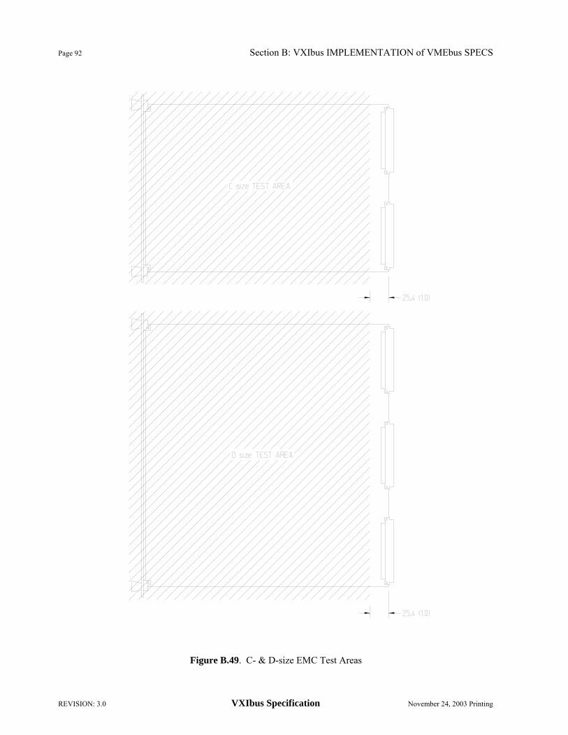
Page 92 Section B: VXIbus IMPLEMENTATION of VMEbus SPECS
REVISION: 3.0 VXIbus Specification November 24, 2003 Printing
Figure B.49. C- & D-size EMC Test Areas

Section B: VXIbus IMPLEMENTATION of VMEbus SPECS Page 93
November 24, 2003 Printing VXIbus Specification REVISION: 3.0
Figure B.50. Adapted A- & D-size & C- & D-size EMC Test Areas

Page 94 Section B: VXIbus IMPLEMENTATION of VMEbus SPECS
REVISION: 3.0 VXIbus Specification November 24, 2003 Printing
Figure B.51. Adapted A- & B-size & C- & D-size EMC Test Areas

Section B: VXIbus IMPLEMENTATION of VMEbus SPECS Page 95
November 24, 2003 Printing VXIbus Specification REVISION: 3.0
B.8.7 Suggested Test Methods
The test methods described in this section are provided as suggestions to the manufacturers of VXIbus mainframes and modules. In the following sections, it is assumed that all measurements which are made using a spectrum analyzer, are for single-frequency stationary signals. Therefore, the bandwidth and sweep rate must be chosen to accurately measure only one frequency component at a time. For modules or mainframes which may generate non-stationary signals, for example, swept signals or transients, the specified techniques cannot be used, but the manufacturer should point out in his documentation what limitations, if any, may arise because of these signals. At higher frequencies, a relatively narrow bandwidth may be necessary to obtain sufficient sensitivity. Note that all induced and conducted tests are based on peak-to-peak measurements, while the radiated tests are based on RMS measurements. B.8.7.1 DC LOAD RIPPLE/NOISE TEST OF MAINFRAMES
The DC load ripple/noise is the maximum periodic and random deviations (PARD) in a power supply voltage under a constant DC load, as used within the power supply industry. Using an oscilloscope with a 10 MHz bandwidth, measure the peak-to-peak AC voltage on each power supply output while varying the DC load from 0 to the mainframe peak current (IMP). The highest value measured is the DC load ripple/noise. The probe should be connected to the backplane using good RF techniques, i.e. using very short leads. B.8.7.2 INDUCED RIPPLE/NOISE TEST OF MAINFRAMES
The Induced Ripple/Noise test requires applying a load of the magnitude and frequencies shown by the Max. Rated Mainframe Dynamic Output Current in Figure B.40 while monitoring the power supply voltage to guarantee that the total induced and DC load ripple voltage does not exceed that of Figure B.41. Set the DC load on the power supply to be half of the rated current (1/2 IMP). For the low frequency tests (up to 10 kHz), drive an active load with a low frequency oscillator to the levels specified. Measure the noise voltage present at an adjacent slot using an oscilloscope. The total induced and DC load ripple/noise is the peak-to-peak value of the AC component. For the higher frequency conducted emission tests, drive a load from a tracking oscillator while monitoring the induced voltage at an adjacent slot with a spectrum analyzer. B.8.7.3 CONDUCTED EMISSIONS TEST OF MODULES
The testing of a module's dynamic current should exclude all effects of the mainframe. Because the mainframe provides current for backplane terminations, clocks and other devices requiring dynamic current, voltage ripple may exist on power pins at various frequencies. This power supply ripple voltage may cause an apparent dynamic current flow into the module that is not caused by any current requirements of the module and should not be included as part of the module's dynamic current. By supplying voltages to the module under test from independent power supplies, the mainframe ripple performance will be isolated from the module dynamic current requirements.
The module being tested should be operating at its worst case current versus frequency requirements.
A current sensor in series with each supply of the module is used to measure the AC portion of the power supply load. Check with an oscilloscope that the module meets the low frequency (up to 10 kHz) conducted emissions requirements. A Spectrum Analyzer is used to measure the higher frequency content of the current. The module is exercised to find the highest readings.

Page 96 Section B: VXIbus IMPLEMENTATION of VMEbus SPECS
REVISION: 3.0 VXIbus Specification November 24, 2003 Printing
This test should be conducted using a backplane having an impedance of less than 0.2 X VS / IS in parallel with a ≥0.1 µF bypass capacitor at the measured slot, where VS is the Module Susceptibility voltage level (Figure B.43) and IS is the Module Conducted current level (Figure B.42). B.8.7.4 CONDUCTED SUSCEPTIBILITY TEST OF MODULES
Induce a voltage between each backplane power supply and module at the maximum voltage shown in Figure B.41 as measured from the module supply pin to ground. Search for potential frequencies where performance is degraded due to the presence of injected noise. For low frequency testing, use a series resistor driven by an active load to induce the specified voltage level. For higher frequencies use current probes appropriate to the frequency range being tested. Be sure the current probe is rated for the DC current being supplied to the module. B.8.7.5 CLOSE-FIELD MAGNETIC EMISSIONS TEST
The equipment to measure the close-field magnetic emissions of a module is a close-field magnetic probe and a spectrum analyzer that operates over the frequency range specified in Figure B.44 or Figure B.45. To cover the frequency range, different probes and spectrum analyzers may be required. It is required that the close-field probes have calibrated antenna factors and that the magnetic loop be within 5 mm of the end of the probe. With the close-field magnetic probe connected to the spectrum analyzer, move the probe tip over the entire module surface to search for potential radiating spots such as seams and holes. At all areas where magnetic radiation is detected, the probe should be oriented to maximize the probe output as displayed on the spectrum analyzer. Using the antenna factors of the close-field probe, calculate the magnetic flux density for each frequency of radiation detected. Flux density levels may not exceed the levels of the appropriate figure. B.8.7.6 CLOSE-FIELD MAGNETIC SUSCEPTIBILITY TEST
The equipment to test the susceptibility of a module consists of a close-field magnetic probe connected to a signal generator that operates over the frequency range specified in Figure B.46 or Figure B.47. To cover the frequency range, different probes and signal generators may be required. It is required that the close-field probes have calibrated antenna factors and that the magnetic loop be within 5 mm of the end of the probe. Connect the close-field magnetic probe to the signal generator. For each frequency tested, set the signal generator to produce a magnetic flux density at the limit given by the appropriate figure for that frequency. Move the probe tip over the entire module surface to search for potential spots where the performance of the module is degraded due to the presence of a magnetic field. The probe tip should be within 1 cm of the surface of the module. B.8.7.7 EXAMPLES OF CLOSE FIELD MAGNETIC PROBES
Examples of close-field probes that meet the above requirements are:
Magnetek Part Number 1846 for frequencies from 20 Hz to 10 kHz
Hewlett-Packard Model 11941 for frequencies from 10 kHz to 30 MHz
Hewlett-Packard Model 11940 for frequencies from 30 MHz to 1 GHz
EMCO Model 7405 Near-Field Probe Set may also be used to complement the above probes.
An amplifier may be needed with any probe to compensate for large probe antenna factors. B.9 Reserved

Section B: VXIbus IMPLEMENTATION of VMEbus SPECS Page 97
November 24, 2003 Printing VXIbus Specification REVISION: 3.0
B.10 Reserved B.11 2eVME Protocol B.11.1 Introduction
Chapter 11 of the VME64x specification details the operation of 2eVME (2 edge VME). The 2eVME protocol allows for the addition of four important features to the VXIbus architecture:
1. Theoretical doubling of the peak block data rate to 160 MB/s
2. Master and Slave terminated 2eVME block Transfers
3. Reduced number of Address Modes
4. Room to add more features in the future
VME64 uses a four-edge handshake to transfer data on the backplane. 2eVME uses a two-edge handshake, reducing the time for a transfer from 100 ns to 50 ns. In a system that allows for 64-bit data transfers, the theoretical maximum data transfer rate is therefore increased to 160 MB/s. The 2eVME protocol works with the 96-pin connector used for the VXIbus allowing for existing backplanes to be used. Additionally the 2eVME protocol can be run along with VME64 cycles on the backplane. 2eVME transfers always use the largest data size available for transfers. For a size C module, transfers are done using A32/D64 and A64/D64 accesses. VME64x adds extensions to the address modifiers used on the bus, called XAM codes and these control the type of transfer performed.
OBSERVATION B.11.1: Full operation of 2eVME on Size A modules requires the use of the 160-pin connector defined by VME64x. Row z of the 160-pin connector contains the RESP* signal, which is required for slave terminated and slave suspended 2eVME transfers. Therefore VXIbus Size A modules are not capable of implementing full 2eVME operation (see Recommendation B.2.1).
OBSERVATION B.11.2: 2eVME slave modules can be added to a chassis containing standard VXIbus slaves. The controller will be able to switch between protocol modes on the backplane and allow interoperation of both types of slaves in a system.
RULE B.11.1: During a 2eVME transaction, a VXIbus SLAVE SHALL toggle DTACK* for an address or data phase within 75 ns after a data strobe (DS0* or DS1*) toggles.
RULE B.11.2: During a 2eVME transaction, a VXIbus MASTER SHALL toggle the appropriate data strobe (DS0* or DS1*) for the next address or data phase within 55 ns after seeing a DTACK* response from a slave.
OBSERVATION B.11.3: The performance of the VXIbus using 2eVME is determined by the signal timing of the master and the slave combined. The above two rules set a maximum “system time” for a 2eVME access of 75 ns + 55 ns = 130 ns. This means that the minimum 2eVME data transfer rate is defined as ‘8 bytes per access’ / ‘130 ns per access’ = 61.5 Mbytes/s. Note that in this observation; the term “access” refers to one half of a 2eVME cycle (i.e. a rising or falling edge of the appropriate signal). Note that a greater performance burden is imposed on master devices to allow for slaves to be implemented in as economical a manner as possible.
RECOMMENDATION B.11.1: For the highest performance in a 2eVME system, VXIbus MASTERS and SLAVES should respond to appropriate signal changes as fast a possible.
Page 98 Section B: VXIbus IMPLEMENTATION of VMEbus SPECS
REVISION: 3.0 VXIbus Specification November 24, 2003 Printing
B.11.2 Transceivers and Connectors
VME64x Rule 11.1 and 11.2 require monotonic rising and falling edges on the address, data and control bus signals used for 2eVME transfers. The VME64x specification calls for transceivers compliant with VITA 2-199x or equivalent parts be used for both high and low going edges.
RECOMMENDATION B.11.2: SN74VMEH22501 transceivers or an equivalent part should be used in 2eVME designs. These parts are noted in the footnote associated with rule 3.1 of VITA 1.5-2003.
OBSERVATION B.11.4: The VITA 2 specification has not been ratified by VITA, but there are several parts that conform to the unratified specification. These include the SN74ABTE16245, the SN74ABTE16246 and the SN74VMEH22501 and their equivalents.
OBSERVATION B.11.5: Designers of 2eVME devices may want to give some thought to the possibility of future enhancements of the VXI specification. If devices are implemented using the recommended transceivers and bus logic is implemented with reprogrammable parts along with an appropriate in-system reprogramming mechanism, then if the specification is enhanced (e.g. 2eSST, 320 MBytes/s) these devices will have the potential to update their capabilities.

Section C: SYSTEM ARCHITECTURE Page 99
November 24, 2003 Printing VXIbus Specification REVISION: 3.0
C. SYSTEM ARCHITECTURE C.1 VXIbus SYSTEM ARCHITECTURE OVERVIEW
The VXIbus architecture allows a wide range of instruments, interface cards or computers from different manufacturers to coexist as modules in the same cardcage. The range of the applications being addressed by different cardcages in the VXIbus family is very broad and, hence, the architecture is intentionally left open to accommodate this flexibility. VXIbus does not define a specific system hierarchy or topology nor does it specify the type of microprocessor, operating system or the type of interface to the host computer. What VXIbus defines is a foundation (or platform) upon which the above decisions can be made while ensuring compatibility between different manufacturers. Figure C.1 shows some of the possible system configurations and may help illustrate the flexibility that is allowed by the VXIbus standard.
Figure C.1. Typical System Configurations
Multiple CPU System
CPU Inst#1
Inst#2
Disp RAM
Host
Stand Alone System
Disc Inst#2
Inst#1
Inst#3
Single CPU System
CPU
488
Inst#1
Inst#2
RAM Inst#3
Host
Inst#3
MfrC
CPUCPUCPU
MfrB
MfrA
CPU CPU
RAM
CPU
InternalHost
(SBC)
Hierarchical Instrument System
Inst#1
Inst#1
Inst#1
Inst#2
Host
Inst#2
Svnt
CPUCPUCPU
SvntCmdr Svnt Cmdr
Inst#2
CPU
Inst #1 Inst #2
Svnt

Page 100 Section C: SYSTEM ARCHITECTURE
REVISION: 3.0 VXIbus Specification November 24, 2003 Printing
As shown by the examples in Figure C.1 there are many topologies possible within the VXIbus architecture. These include single CPU systems that centralize the intelligence for all their instrument modules, multiple CPU systems with distributed intelligence and stand alone mainframes that contain a host computer running user applications. Each of these topologies has different communication needs which are met by a layered set of communication protocols illustrated in Figure C.2.
Figure C.2. VXIbus Communication Layers In order to support automatic system and memory configuration, the VXIbus standard specifies a minimum amount of capability on each device regardless of its function. A VXIbus device (see Section C.2, "Device Operation"), being the lowest element of a hierarchy, has a set of "Configuration Registers", all totally accessible from P1 on VMEbus which allow the system to identify the device, its class, model and manufacturer, address space (A16, A24, A32, A64) and memory requirements. VXIbus devices with only this minimum level of capability are called REGISTER BASED DEVICES. As an example, the single CPU system shown in Figure C.1 may implement all of its instruments using only Register Based Devices with device specific protocols on how the CPU communicates with each of those instruments. VXIbus also defines MEMORY DEVICES, (See Section C.2.3, "Memory Devices") that can be identified as RAM, ROM or other memory types and be configured in contiguous blocks of memory based on speed or memory type.
If a higher level of communication ability between modules is desired in the system, VXIbus defines a class of devices called MESSAGE BASED DEVICES. In addition to the configuration registers mentioned above, Message Based Devices are required to have communication registers that are accessible to other modules in the system. Each device in the system can then use specific communication protocols such as VXIbus's Word Serial Protocol (See Section C.3.3.1, "Word Serial Protocols") to communicate with other devices. The multi-CPU system shown in Figure C.1 is a good example of this type of system where each instrument is a Message Based Device and is therefore capable of receiving instructions from a host or a common host interface. Note that by agreeing on a class of communication protocols, such as Word Serial, different manufacturers can now build any of those instruments and be assured of compatibility with the rest of the system. Higher level communication protocols, referred to as Shared Memory Protocols in Figure C.2, can later be defined using these platforms.
Configuration Registers
Communication Registers
Device Specific Protocols
Shared Memory Protocol
Word Serial Protocol
Device Specific Protocols
Device Specific Protocols
488.2 Syntax
488-VXIbus Protocol
Device Specific Protocols

Section C: SYSTEM ARCHITECTURE Page 101
November 24, 2003 Printing VXIbus Specification REVISION: 3.0
Communication between VXIbus devices is based on a hierarchical device relationship involving COMMANDERS and SERVANTS. For many systems, such as the single CPU system shown in Figure C.1, only the first level of this hierarchy exists. In that example, the CPU and host interface device is a Commander which controls the three instrument Servants. A Commander is able to initiate communication with its Servants based on their capabilities. If the Servants are Message Based Devices, such communication can take place using COMMANDS which are described by the Word Serial Protocols. Communication with Register Based Servants is device dependent and may vary between systems. The Commander/Servant hierarchy can be nested since a Message Based Device may be a Commander as well as a Servant to the next level above it. The hierarchical instrument system of Figure C.1 is an example of such a system. Instrument #1 and #2 are shown as multi device instruments that have two Servants each while the instruments themselves may be Servants to the host interface.
A common element that instruments may desire to share among them is the interface to the host computer as shown in the Multi-CPU system example in Figure C.1. The 488-VXIbus interface device (see Section D.2, "488-VXIbus Interface") is an example of such a device. VXIbus defines this as a function specific Message Based Device with communication protocols that support IEEE-488 functions. This device, if provided, may be shared by the instruments needing to be accessed by the host. Other host or peripheral interfaces such as RS-232, LAN or Human Interfaces can be designed in a similar fashion.
Regardless of the topology of the VXIbus cardcage (See Figure C.1.), VMEbus's multiple bus master architecture demands a minimal amount of system related functions that are performed by a central RESOURCE MANAGER (see Section C.4.1, "Resource Manager"). The following are some of the functions a Resource Manager MAY need to perform depending on the topology of the system.
• Address map configuration. To configure the A24, A32 and A64 address maps and assign blocks of addresses to the devices requiring them.
• Determining System Hierarchy. In a multi-CPU system, the potential for more than one processor to try and control another device exists. The Commander/Servant hierarchies determined by the Resource Manager prevent this type of conflict.
• Allocating Shared System Resources. A central Resource Manager (e.g. operating system) is needed in systems that share blocks of memory for communication or share other hardware resources such as trigger busses.
• Performing System Self Test and Diagnostics.
• Initialization of all Commanders in the system.

Page 102 Section C: SYSTEM ARCHITECTURE
REVISION: 3.0 VXIbus Specification November 24, 2003 Printing
C.2 DEVICE OPERATION C.2.1 Device Overview
Devices are the lowest logical component in the VXIbus system. Normally a device will consist of one VXIbus module. However, multi-board devices and multi-device boards are permitted. There is a unique Logical Address associated with each device in the system. Examples of devices are computers, multimeters, multiplexers, oscillators, operator interfaces and counters. VXIbus devices may be categorized by their supported protocols into four classes as illustrated in Figure C.3. • Message Based Devices support the VXIbus configuration and communication protocols. This category
includes only devices with Commander and/or command based Servant elements. Examples of Message Based Devices are any devices with local intelligence that require a level of communication capability such as DMM's, Spectrum Analyzers, Display Controllers, 488-VXIbus interface devices, Switch controllers, etc.
• Register Based Devices support VXIbus register maps, but no VXIbus communication protocols. This category is comprised of devices having Register Based Servant elements. Typically Register Based Devices are simple, inexpensive devices such as simple switches, digital I/O cards, simple serial interface cards and in general any card that requires little or no local intelligence. More sophisticated devices could also be implemented as Register Based Devices that rely on Message Based Devices for their instructions.
• Memory Devices have configuration registers and contain certain attributes of a Memory Device such as type and access time, etc. but have no other VXIbus defined registers or protocols. Bubble memory, RAM and ROM cards are in this category.
• Extended Devices are special purpose VXIbus devices that have configuration registers so they can be identified by the system. This category of devices will allow for definition of future device classes to support further levels of compatibility.
Hybrid Devices are VMEbus compatible devices that know about VXIbus devices and have the ability to communicate with them or make use of them, but don't themselves comply with VXIbus device requirements. Existing VMEbus boards with the appropriate software to make use of VXIbus devices are an example of this class of device.
Non-VXIbus devices are VMEbus devices that do not comply with or use any of the VXIbus requirements. C.2.1.1 DEVICE SLAVE CAPABILITIES
All VXIbus devices have a common set of VMEbus slave attributes. These include standard memory maps, common addressing modes and standard register definitions. C.2.1.1.1 Device Addressing
All VXIbus devices have registers located within 64 byte blocks in the A16 address space. The base address of a device's registers is determined by the device's unique Logical Address. The Logical Address selector is an eight (8) bit selector which has 256 unique settings. The Logical Address is the value indicated by this selector and corresponds to bits 6 →13 of the device register base address. Bits 14 and 15 of the base address are both 1 and the base address is:
4915264 +×V where V is the device's Logical Address.

Section C: SYSTEM ARCHITECTURE Page 103
November 24, 2003 Printing VXIbus Specification REVISION: 3.0
Figure C.3. Device Classifications
VMEbus Devices
Non-VXIbus Devices
Hybrid Devices
VXIbus Devices
Register Based
Devices
Extended Devices
Memory Devices
Message Based
Devices
A16 / A24 A16 / A32 A16 / A64
Register Based
A16 Only Register Based CPU
???
Instrument
Human Interface
ResourceManager
???
MUX
Source
A/D
???
MUX
Source
A/D

Page 104 Section C: SYSTEM ARCHITECTURE
REVISION: 3.0 VXIbus Specification November 24, 2003 Printing
If a device requires fewer than 64 bytes of address space, all of it may reside within the defined 64 byte block. Otherwise, it has additional registers in the A24, A32 or A64 address space. The base address of a device's A24, A32 or A64 registers is programmed via an Offset register in the configuration portion of its A16 registers.
RULE C.2.1: Every VXIbus device SHALL have a non-volatile means of selecting Logical Addresses and implement the defined A16 addressing scheme.
RULE C.2.2: IF a VXIbus device has A24, A32 or A64 registers, THEN the base address of such registers SHALL be programmable via its Offset register in its A16 configuration area.
RULE C.2.3: All VXIbus slaves SHALL implement A16 addressing modes and have configuration registers available in the A16 address space.
PERMISSION C.2.1: VXIbus slaves MAY also implement A24, A32 or A64 addressing modes.
RULE C.2.4: IF a VXIbus slave implements A24, A32 or A64 addressing modes in addition to A16 addressing, THEN it SHALL implement only one of the additional addressing modes (A24, A32, A64).
OBSERVATION C.2.1: The additional addressing modes (A16/A24, A16/A32 and A16/A64) are mutually exclusive to one another. If Enhanced Capability is defined in the ID Register, then the addressing mode of the device is defined in the Enhanced Capabilities Register. Currently A16/A64 is the only enhanced mode defined.
RULE C.2.5: VXIbus slaves SHALL implement D16.
RECOMMENDATION C.2.1: VXIbus slaves should implement D08 (EO).
PERMISSION C.2.2: VXIbus slaves MAY implement D32 and/or D64.
The preceding rules, etc. are summarized in the following table.
IF A16 A24 A32 A64
THEN D08(EO) D16 D32 D64
SLAVE A16 • MAY MAY MAY REC. SHALL MAY MAY SLAVE A24 SHALL • N.A. N.A. REC. SHALL MAY MAY SLAVE A32 SHALL N.A. • N.A. REC. SHALL MAY MAY SLAVE A64 SHALL N.A. N.A. • REC. SHALL MAY MAY
N.A. – Not Allowed REC. - Recommended
RULE C.2.6: VXIbus slaves SHALL NOT rely on A40 or MD32 modes for proper operation.

Section C: SYSTEM ARCHITECTURE Page 105
November 24, 2003 Printing VXIbus Specification REVISION: 3.0
C.2.1.1.2 Configuration Registers
The following diagram contains the register map for the Configuration registers of a VXIbus device. These registers are located in the A16 address space by the Logical Address selector as described previously. Revision 3.0 of this specification adds the Enhanced Capabilities Register at address 1C 16 (formerly a device class dependent register). This location was chosen to facilitate backwards compatibility with existing modules because it is not defined for any Device Class by the VXI Consortium.
3F 16
20 16
DEVICE DEPENDENT REGISTERS
1E 16 DEVICE CLASS DEPENDENT REGISTER
1C 16 Enhanced Capabilities Register 1B 16
08 16
DEVICE CLASS DEPENDENT REGISTERS
06 16 Offset Register
04 16 Status/Control Register
02 16 Device Type
00 16 ID/Logical Address Register The fields of the above table are defined as follows:
ID Register: A read of this 16-bit register provides information about the device's configuration. Its contents are defined in the following table.
Bit # 15 ← 14 13 ← 12 11 ← 0
Contents Device Class
Address Space
Manufacturer ID
• Device Class: This field indicates the classification of the VXIbus device according to the
following table.
Value Class 00 Memory 01 Extended 10 Message Based 11 Register Based

Page 106 Section C: SYSTEM ARCHITECTURE
REVISION: 3.0 VXIbus Specification November 24, 2003 Printing
• Address Space: This field indicates the addressing mode(s) of the device's operational registers according to the following table.
Value Mode
00 A16/A24 01 A16/A32 10 Enhanced Capability 11 A16 Only
• Manufacturer ID: This number uniquely identifies the manufacturer of the device. The list of ID numbers
is maintained by the VXIbus Consortium. Each VXIbus device manufacturer has exactly one Manufacturer ID number. Numbers are assigned to manufacturers in decreasing order beginning with number 4095. See Section A.1, "Manufacturer ID Numbers", for information on obtaining a manufacturer ID number.
OBSERVATION C.2.2: ID number 3840 (F0016) is reserved for user customized devices and any other unique special function device.
Logical Address: This 16-bit write register is defined by the optional Dynamic Configuration protocol. See Section F, "Dynamic Configuration".
Device Type: This 16-bit register contains a device dependent type identifier. The read contents of this register are defined below
Bit # 15 ← 12 11 ← 0
Contents Required Memory
Model Code
• Required memory [Only required for A16/A24, A16/A32 and A16/A64 devices]: These 4 bits contain a
number m, which is between 0 and 15. The required memory usage is defined as
For Address Mode Memory usage =
A16/A24 223-m A16/A32 231-m A16/A64 263-m
The address mode for the device is found in the address space field of the ID register or if the address space field is set to enhanced capabilities (102), then the address mode is found in the address mode field of the enhanced capabilities register. The appropriate equation from the above table gives the amount of A24, A32 or A64 memory space (in bytes) resident on the device. This also means that the device must decode addresses to this resolution.
OBSERVATION C.2.3: The above algorithm for determining memory requirements allows devices with minimal memory requirements to let the Required Memory bits float to a high level and minimizes hardware requirements for low cost devices.
In the case of an A16 only device, these four bits are the upper bits of the Model Code

Section C: SYSTEM ARCHITECTURE Page 107
November 24, 2003 Printing VXIbus Specification REVISION: 3.0
OBSERVATION C.2.4: The minimum size of an A24 device's memory is 256 bytes. The maximum size of the memory map is 1/2 of the complete A24 VMEbus address space, i.e. 8,388,608 bytes (8 Mbytes).
OBSERVATION C.2.5: The minimum size of an A32 device's memory is 65,536 bytes (64 kbytes). The maximum size of the memory map is 1/2 of the complete A32 VMEbus address space, i.e. 2,147,483,648 bytes (2 Gbytes).
OBSERVATION C.2.6: The minimum size of an A64 device's memory is 281,474,976,710,656 (281 Tbytes). The maximum size of the memory map is 1/2 of the complete A64 VMEbus address space, i.e. 9,223,372,036,854,775,808 bytes (9 Ebytes).
SUGGESTION C.2.1: It would be a good idea to limit the memory space of any device to 1/4 of the available address range for the device. This would facilitate having more than one device in each possible address space.
• Model Code: This field contains a unique card identifier which is defined by the manufacturer. In the case of an A16 only device, this field occupies all 16 bits of the Device Type register.
OBSERVATION C.2.7: Model codes 0-255 (0-FF16 are reserved for Slot 0 devices. See Rules C.4.18 and C.4.19 in Section C.4.3, "VXIbus Subsystem Slot 0".
A write to the Device Type register location has no effect. Its use is reserved for VXIbus definition.
Status Register: A read of this register provides information about the Device's status as defined in the following table.
Bit # 15 14 13 ← 4 3 2 1 ← 0
Contents A24/A32/A64 Active MODID* Device
Dependent Ready Passed Device Dependent
• A24/A32/A64 Active: This bit is only required for A16/A24, A16/A32 or A16/A64 devices. A one (1) in this field indicates that its A24, A32 or A64 registers can be accessed. This bit reflects the state of the Control register's A24/A32/A64 Enable bit.
RULE C.2.7: The A24/A32/A64 Active bit in an A16/A24, A16/A32 and A16/A64 device SHALL be cleared (set to zero (0)) whenever SYSRESET* is asserted and changed only by a write of the A24/A32/A64 Enable bit in the device's Control register.
OBSERVATION C.2.8: In an A16 only device the A24/A32/A64 Active bit is device dependent.
• MODID*: A one (1) in this field indicates that the device is not selected via the P2 MODID line. A zero (0) indicates that the device is selected by a high state on the P2 MODID line.
RULE C.2.8: IF A device does not implement MODID capability (P1 only device) THEN the device's MODID* bit SHALL always be set to one (1).
RULE C.2.9: IF A device implements MODID capability, THEN the device's MODID* bit SHALL always be set or reset within 1 ms of the module's MODID line being set or reset.

Page 108 Section C: SYSTEM ARCHITECTURE
REVISION: 3.0 VXIbus Specification November 24, 2003 Printing
• Ready: This field serves two purposes: 1. After the power-on initialization sequence (see Section C.2.1.2, "Device Initialization and
Diagnostics") a one (1) in this field in combination with a zero (0) in the Passed field indicates that the device has failed register initialization.
2. After the power-on initialization sequence, a one (1) in this field in combination with a one (1) in the Passed field indicates that the device is ready to execute its full set of operational commands.
OBSERVATION C.2.9: The Ready bit indicates that a device is ready to accept its full set of operational commands. This "readiness" is determined in a device dependent manner. A standard definition of readiness for Message Based Devices is given in Section C.2.4.5, "Message Based Device Configuration".
• Passed: A zero (0) in this field indicates that the device is either executing or has failed its self test. A one (1) indicates that the self test has successfully completed.
RULE C.2.10: IF a device does not implement a power-on self test, THEN its Passed bit SHALL always be set to one (1).
PERMISSION C.2.3: The device dependent bits of the Status register MAY be defined to indicate the state of the corresponding bits of the Control register.
Control Register: A write to this register causes specific actions to be executed by the device.
These actions are described in the following table.
Bit # 15 14 ← 2 1 0
Contents A24/A32/A64 Enable
Device Dependent Sysfail Inhibit Reset
• A24/A32/A64 Enable: A one (1) in this field enables access to the device's A24, A32 or A64 VMEbus registers. A zero (0) disables such access.
• Device Dependent: The bits in this field are available to the device designer for device and/or application specific control.
OBSERVATION C.2.10: A Resource Manager which lacks device specific knowledge of a device will always write a one to each of the device dependent bits of a device's Control register whenever it writes to that Control register to change any of the VXIbus defined bits.
RECOMMENDATION C.2.2: The device dependent bits of the Control register should be implemented so that writing ones to these bits will not disturb the initial state of the device. This will permit a Resource Manager or Commander (which lacks device specific knowledge) to write the VXIbus defined bits without causing some undesired activity on the device.
• Sysfail Inhibit: A one (1) in this field disables the device from driving the SYSFAIL* line.
• Reset: A one (1) in this field forces the device into a reset state.
RULE C.2.11: IF a device's Commander writes a one (1) to the device's Reset bit, THEN the Commander must not write a zero (0) to that device's Reset bit within the following 100 ms.
See Section C.2.1.2, "Device Initialization and Diagnostics", for more information on the operation of the above bits.
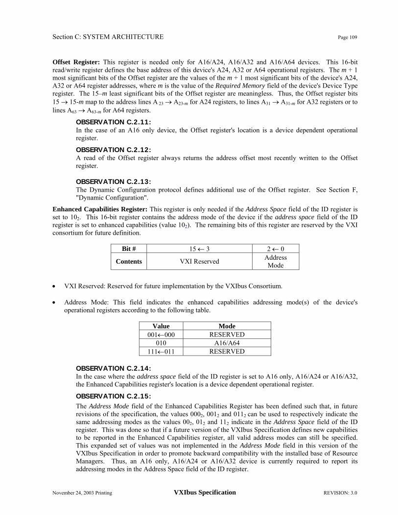
Section C: SYSTEM ARCHITECTURE Page 109
November 24, 2003 Printing VXIbus Specification REVISION: 3.0
Offset Register: This register is needed only for A16/A24, A16/A32 and A16/A64 devices. This 16-bit read/write register defines the base address of this device's A24, A32 or A64 operational registers. The m + 1 most significant bits of the Offset register are the values of the m + 1 most significant bits of the device's A24, A32 or A64 register addresses, where m is the value of the Required Memory field of the device's Device Type register. The 15–m least significant bits of the Offset register are meaningless. Thus, the Offset register bits 15 → 15-m map to the address lines A 23 → A23-m for A24 registers, to lines A31 → A31-m for A32 registers or to lines A63 → A63-m for A64 registers.
OBSERVATION C.2.11: In the case of an A16 only device, the Offset register's location is a device dependent operational register.
OBSERVATION C.2.12: A read of the Offset register always returns the address offset most recently written to the Offset register.
OBSERVATION C.2.13: The Dynamic Configuration protocol defines additional use of the Offset register. See Section F, "Dynamic Configuration".
Enhanced Capabilities Register: This register is only needed if the Address Space field of the ID register is set to 102. This 16-bit register contains the address mode of the device if the address space field of the ID register is set to enhanced capabilities (value 102). The remaining bits of this register are reserved by the VXI consortium for future definition.
Bit # 15 ← 3 2 ← 0
Contents VXI Reserved Address Mode
• VXI Reserved: Reserved for future implementation by the VXIbus Consortium. • Address Mode: This field indicates the enhanced capabilities addressing mode(s) of the device's
operational registers according to the following table.
Value Mode 001←000 RESERVED
010 A16/A64 111←011 RESERVED
OBSERVATION C.2.14:
In the case where the address space field of the ID register is set to A16 only, A16/A24 or A16/A32, the Enhanced Capabilities register's location is a device dependent operational register.
OBSERVATION C.2.15: The Address Mode field of the Enhanced Capabilities Register has been defined such that, in future revisions of the specification, the values 0002, 0012 and 0112 can be used to respectively indicate the same addressing modes as the values 002, 012 and 112 indicate in the Address Space field of the ID register. This was done so that if a future version of the VXIbus Specification defines new capabilities to be reported in the Enhanced Capabilities register, all valid address modes can still be specified. This expanded set of values was not implemented in the Address Mode field in this version of the VXIbus Specification in order to promote backward compatibility with the installed base of Resource Managers. Thus, an A16 only, A16/A24 or A16/A32 device is currently required to report its addressing modes in the Address Space field of the ID register.

Page 110 Section C: SYSTEM ARCHITECTURE
REVISION: 3.0 VXIbus Specification November 24, 2003 Printing
OBSERVATION C.2.16: The enhanced capabilities setting should not be interpreted to solely mean A16/A64 mode. Although currently this is the only defined function, designers should be cognizant of the fact that additional features may be added in future revisions of the VXIbus specification.
C.2.1.1.3 Device Class Dependent Registers
The definition of the VXIbus Device Class Dependent Registers varies with the class of the device, i.e. Message Based, Register Based, etc. C.2.1.1.4 Device Dependent Registers
VXIbus Device Dependent Registers are user definable. C.2.1.1.5 Address Modifiers
Revision 3.0 of the VXIbus specification adds Extended Address Modifier (XAM) codes as defined by VME64x for use with the 2eVME protocol.
RULE C.2.12: VXIbus device A16 registers SHALL respond to address modifiers 2916 (A16 Non-Privileged Access) and 2D16 (A16 Supervisory Access) only.
RULE C.2.13: VXIbus device A24 registers SHALL respond to address modifiers 3D16 (A24 Supervisory Data Access) and 3E16 (A24 Supervisory Program Access).
RECOMMENDATION C.2.3: VXIbus device A24 registers should also respond to address modifiers 3916 (A24 Non-Privileged Data Access) and 3A16 (A24 Non-Privileged Program Access).
PERMISSION C.2.4: VXIbus device A24 registers MAY respond to any of the address modifiers 3216 (A24 Lock Command), 3816 (A24 Non-Privileged Multiplexed Block Transfer), 3B16 (A24 Non-Privileged Block Transfer), 3C16 (A24 Supervisory Multiplexed Block Transfer) and 3F16 (A24 Supervisory Block Transfer).
RULE C.2.14: VXIbus device A24 registers SHALL NOT respond to any address modifier other than 3216, 3816, 3916, 3A16, 3B16, 3C16, 3D16, 3E16 or 3F16.
RULE C.2.15: VXIbus device A32 registers SHALL respond to address modifiers 0D16 (A32 Supervisory Data Access) and 0E16 (A32 Supervisory Program Access).
RECOMMENDATION C.2.4: VXIbus device A32 registers should also respond to address modifiers 0916 (A32 Non-Privileged Data Access) and 0A16 (A32 Non-Privileged Program Access).
RECOMMENDATION C.2.5: VXIbus device A32 registers in devices that require high performance should also respond to address modifier 2016 with XAM 0116 (6U, A32/D64 2eVME Transfer).
PERMISSION C.2.5: VXIbus device A32 registers MAY respond to any of the address modifiers 0516 (A32 Lock Command), 0816 (A32 Non-Privileged Multiplexed Block Transfer), 0B16 (A32 Non-Privileged Block Transfer), 0C16 (A32 Supervisory Multiplexed Block Transfer) and 0F16 (A32 Supervisory Block Transfer).
Section C: SYSTEM ARCHITECTURE Page 111
November 24, 2003 Printing VXIbus Specification REVISION: 3.0
RULE C.2.16: VXIbus device A32 registers SHALL NOT respond to any address modifier other than 0516, 0816, 0916, 0A16, 0B16, 0C16, 0D16, 0E16, 0F16 or 2016 w/XAM 0116.
RULE C.2.17: VXIbus device A64 registers SHALL respond to address modifiers 0116 (A64 Single Transfer Access).
RECOMMENDATION C.2.6: VXIbus device A64 registers in devices that require high performance should also respond to address modifiers 0016 (A64 64-bit Block Transfer [MBLT]), 0316 (A64 Block Transfer [BLT]) and 2016 with XAM 0216 (6U, A64/D64 2eVME Transfer).
PERMISSION C.2.6: VXIbus device A64 registers MAY respond to address modifier 0416 (A64 Lock Command).
RULE C.2.18: VXIbus device A64 registers SHALL NOT respond to any address modifier other than 0016, 0116, 0316, 0416 or 2016 w/XAM 0216.
OBSERVATION C.2.17: The preceding rules prevent any overlapping of the defined VMEbus address spaces. They do implicitly allow the use of address modifiers not specifically mentioned. C.2.1.2 DEVICE INITIALIZATION and DIAGNOSTICS
The VMEbus provides a minimal self-test reporting facility (SYSFAIL*). VXIbus devices implement an extended reporting strategy that addresses the ambiguities of the VME64 specification. In addition, the VXIbus initialization process provides for a VXIbus device to initialize its own configuration registers. C.2.1.2.1 Overview The VXIbus initialization sequence provides the following services:
• Assertion of SYSFAIL* at power-on to indicate a self-test condition.
• Status register indication of self-test status.
• Optional faceplate LED indication of self-test status, labeled Failed.
• Time limit for completion of a normal self-test.
• Control register bits for disabling SYSFAIL* driver and resetting the device.
• A waiting period for initialization of the device's configuration registers.
The initialization sequence is implemented with an internal state machine, the Passed and Ready bits of the Status register, the Reset and Sysfail Inhibit bits of the Control register, a VMEbus SYSFAIL* driver and the Failed LED.
A typical power-on initialization sequence proceeds as follows.
1. 1. At power-on SYSRESET* is asserted, forcing the device into a reset condition. At this time the Passed, Reset, Ready and Sysfail Inhibit bits are all cleared (to 0). The device asserts SYSFAIL* and lights its Failed LED (if present).
2. When SYSRESET* is unasserted, the device begins its self test. This self test initializes the device's capability to execute VXIbus communication.

Page 112 Section C: SYSTEM ARCHITECTURE
REVISION: 3.0 VXIbus Specification November 24, 2003 Printing
3. If the device fails its self test, it leaves its Passed and Ready bits cleared, SYSFAIL* asserted and its Failed LED lighted. After 4.9 seconds, these conditions indicate a self test failure.
4. When the device successfully completes its self test, it sets (to 1) its Passed bit, de-asserts SYSFAIL* and turns off its Failed LED (if present). It is then ready to commence VXIbus communications.
5. If the device requires further initialization, as in the case of a Message Based Device, its Ready bit remains cleared (to 0). When it is ready to accept its normal operational commands, it sets (to 1) its Ready bit.
6. A VMEbus Master may turn off a failed device's SYSFAIL* driver by setting (to 1) its Sysfail Inhibit bit. It may also force the device into a reset condition by setting its Reset bit.
7. When the Reset bit is cleared, the device begins another self test sequence.
A device may initialize its configuration registers any time within the 4.9 seconds after the unassertion of SYSRESET*, typically in the following sequence.
1. At power-on SYSRESET* is asserted, forcing the device into a reset condition, disabling all VMEbus access to its configuration registers. The device asserts SYSFAIL* and lights its Failed LED (if present).
2. When SYSRESET* is unasserted, the device begins initialization of its configuration registers. At this point VMEbus access remains disabled, SYSFAIL* remains asserted and the Failed LED is lighted (if present).
3. After initializing to zero (0) the Passed, Reset and Sysfail Inhibit bits and initializing to one (1) the Ready bit, the device may enable VMEbus access to its configuration registers.
4. If the device is unable to initialize the Passed, Reset, Sysfail Inhibit and Ready bits, its configuration registers will remain inaccessible to the VMEbus.
5. After initializing all of its configuration registers, the device enables VMEbus access to its registers (if it hasn't already), clears the Ready bit and begins its self test.
6. If the device fails to completely initialize its configuration registers, it enables VMEbus access to its registers (if it hasn't already), leaves its Passed bit cleared, its Ready bit set, SYSFAIL* asserted and its Failed LED lighted (if present). After 4.9 seconds, these conditions indicate an initialization error.
7. When the device successfully completes both its configuration register initialization and its self test, it sets (to 1) its Passed bit, de-asserts SYSFAIL* and turns off its Failed LED (if present). It is then ready to commence VXIbus communications.
C.2.1.2.2 Self Test Operation
The initialization sequence is characterized by eight states as illustrated in Figure C.4.
• Hard Reset: This is the state of the device when the SYSRESET* line is true. While in this state the device is inactive and its Status and Control registers may be initialized. The SYSFAIL* line is driven low and the failed LED is lighted.
• Config Reg Init: During this optional state, the device configures its own configuration registers. This may include setting its Logical Address and its ID and Device Type register values, as well as initializing its Status, Control and Offset registers. Initially, a device's configuration registers may be inaccessible via the VMEbus. In this state, the device continues to assert SYSFAIL* and its optional Failed LED is lighted. The config reg init state and any additional self test must complete within 4.9 seconds of SYSRESET*'s unassertion or clearing of the Reset bit. If the configuration register initialization fails before the device enables VMEbus access to its configuration registers, the device remains in the CONFIG REG INIT state until the next Hard Reset. Before register access is enabled, the Passed bit is set to zero

Section C: SYSTEM ARCHITECTURE Page 113
November 24, 2003 Printing VXIbus Specification REVISION: 3.0
(0) and the Ready bit is set to one (1). The ID and Device Type registers may be initialized either before or after register access is enabled.
• Self Test: In the Self Test state, the device tests and initializes the functionality necessary for VXIbus communications. This test must complete within 4.9 seconds of SYSRESET*'s unassertion or clearing of the Reset bit. If the self test fails, the device enters the failed state. If it passes, it enters the passed state. While in the self test state the device's VMEbus interface is active. However the device is incapable of responding to any commands other than Reset and Sysfail Inhibit. While in the SELF TEST state, the Passed bit remains cleared (to 0), the Ready bit is also cleared and SYSFAIL* remains asserted.
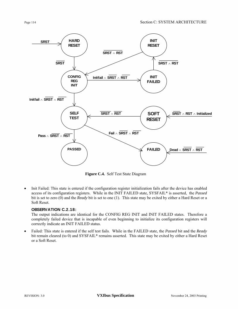
Page 114 Section C: SYSTEM ARCHITECTURE
REVISION: 3.0 VXIbus Specification November 24, 2003 Printing
Figure C.4. Self Test State Diagram • Init Failed: This state is entered if the configuration register initialization fails after the device has enabled
access of its configuration registers. While in the INIT FAILED state, SYSFAIL* is asserted, the Passed bit is set to zero (0) and the Ready bit is set to one (1). This state may be exited by either a Hard Reset or a Soft Reset.
OBSERVATION C.2.18: The output indications are identical for the CONFIG REG INIT and INIT FAILED states. Therefore a completely failed device that is incapable of even beginning to initialize its configuration registers will correctly indicate an INIT FAILED status.
• Failed: This state is entered if the self test fails. While in the FAILED state, the Passed bit and the Ready bit remain cleared (to 0) and SYSFAIL* remains asserted. This state may be exited by either a Hard Reset or a Soft Reset.
Dead ∧ SRST ∧ RST
Pass ∧ SRST ∧ RST Fail ∧ SRST ∧ RST
SRST ∧ RST ∧ Initialized SRST ∧ RST
Initfail ∧ SRST ∧ RST
SRST ∧ RST
SRST ∧ RST
SRST HARD RESET
FAILED PASSED
SOFT RESET
SELF TEST
INIT FAILED
CONFIG REG INIT
INIT RESET
SRST
Initfail ∧ SRST ∧ RST

Section C: SYSTEM ARCHITECTURE Page 115
November 24, 2003 Printing VXIbus Specification REVISION: 3.0
OBSERVATION C.2.19: The output indications are identical for the SOFT RESET, SELF TEST and FAILED states. Therefore, a completely failed device that is incapable of even beginning a self test will correctly indicate a failed status.
• Passed: This state is entered when the self test has successfully terminated. The SYSFAIL* line is unasserted and the Passed bit of the Status register is set (to 1). While in the PASSED state, the device is capable of fully supporting VXIbus communications.
OBSERVATION C.2.20: The passed state can be further sub-divided in a device dependent manner. For Message Based Devices three sub-states are defined in Section C.2.4.4, "Message Based Device Operation".
• Soft Reset: This state is entered when the Reset bit of the Control register is set to one. While in this state a device is inactive, interrupts which are pending are unasserted and all pending bus requests are removed. While in this state the device's VMEbus slave interface is active, however the device is incapable of responding to any commands other than Reset and Sysfail Inhibit. While in this state the Status register must accurately reflect the state of the device.
OBSERVATION C.2.21: The VME64 Specification (Section 3.3.2, "Requester") defines the protocols for proper removal of bus requests.
• Init Reset: This state is similar to the SOFT RESET state, except that the device's configuration registers have not been initialized (and therefore are meaningless).
The mnemonics used in the self test state diagram are listed in the following table:
SELF TEST Mnemonics Mnemonic Name Type
SRST = SYSRESET* asserted (low) VMEbus line RST = Reset (1=true) Control register bit Fail = Self Test Failed Internal signal Pass = Self Test Failed Internal signal Dead = Device Failure Internal signal Initialized = Config Regs Initialized Internal signal Initfail = Init Config Regs Failed Internal signal
OBSERVATION C.2.22: The Fail, Pass and Dead signals are generated by the Initialization process as sequencing signals to itself.
OBSERVATION C.2.23: The Dead signal is generated by the device whenever it detects a catastrophic failure during normal operation.
Page 116 Section C: SYSTEM ARCHITECTURE
REVISION: 3.0 VXIbus Specification November 24, 2003 Printing
The states of the initialization sequence produce the Status register indications given in the following table.
SELF TEST Status Bits Status Register Bits State Passed Ready
HARD RESET (0) (0/1) CONFIG REG INIT (0) (1) INIT FAILED 0 1 SELF TEST 0 0 FAILED 0 0 PASSED 1 1/1 SOFT RESET 0 0 INIT RESET 0 1
OBSERVATION C.2.24: The Status register is inaccessible during the HARD RESET state. However, in many cases its bits will be initialized by SYSRESET* to indicate the device's state (CONFIG REG INIT or SELF TEST) immediately following HARD RESET.
OBSERVATION C.2.25: The device's configuration registers may be inaccessible throughout the CONFIG REG INIT state. The Status register indications shown are meaningful only after VMEbus access has been enabled.
The status of the SYSFAIL* driver and the optional failed LED may be derived from the states of the Passed Status register bit and the Sysfail Inhibit Control register bit as described in the following table.
SELF TEST Indicators Register Bits Indicators
Passed Status Bit
Sysfail Inhibit Control Bit
SYSFAIL* Driver
FAILED LED
0 0 LOW ON 0 1 HIGH ON 1 X HIGH OFF

Section C: SYSTEM ARCHITECTURE Page 117
November 24, 2003 Printing VXIbus Specification REVISION: 3.0
The VMEbus SYSRESET* line and the Control register interact to force the device into particular states as described in the following table.
SYSRESET* and Control Register Interactions Signal
SYSRESET* Line
Reset Bit
Current
State Effect
LOW X X HARD RESET state
↑ X HARD RESET Begin CONFIG REG INIT (if implemented)
or SELF TEST
HIGH 1 SELF TEST, PASSED, or FAILED SOFT RESET State
HIGH 1 INIT FAILED INIT RESET State
HIGH ↓ SOFT RESET Begin SELF TEST
HIGH ↓ INIT RESET Begin CONFIG REG INIT
RULE C.2.19: All devices implementing power-on self tests SHALL implement the HARD RESET, SELF TEST, PASSED, FAILED and SOFT RESET states of the self test function.
RULE C.2.20: Any device not implementing the initialization sequence SHALL NOT assert SYSFAIL* or clear (to 0) its Passed bit at any time.
RULE C.2.21: A device SHALL NOT implement a CONFIG REG INIT and SELF TEST combination of more than 4.9 seconds total duration.
RULE C.2.22: A device's ID and Device Type registers SHALL be valid before it enters the SELF TEST state.
PERMISSION C.2.7: A device MAY execute self test operations while in the CONFIG REG INIT state, provided that its Ready bit is set (to 1), until its configuration registers have been initialized.
RULE C.2.23: A device's VXIbus interface SHALL be fully operational before entering the PASSED state.
PERMISSION C.2.8: A device MAY enter the FAILED state any time it detects a catastrophic failure during normal operation.
OBSERVATION C.2.26: The Sysfail Inhibit bit of the Control register is used to disable the device's SYSFAIL* driver.
OBSERVATION C.2.27: The Failed LED is optional. Other LED's such as a SYSFAIL* inhibit indicator may also be optionally implemented.

Page 118 Section C: SYSTEM ARCHITECTURE
REVISION: 3.0 VXIbus Specification November 24, 2003 Printing
OBSERVATION C.2.28: Once a device has enabled access of its configuration registers, they will remain accessible until the next Hard Reset.
RULE C.2.24: Once a device enters either the INIT FAILED or SELF TEST state, it SHALL NOT change its Logical Address except as provided for by Dynamic Configuration (see Section F, "Dynamic Configuration"), until the next Hard Reset.
OBSERVATION C.2.29: A Soft Reset will not affect a device's Logical Address, configuration register accessibility, Offset register or A24/A32/A64 Active bit.
RULE C.2.25: After either a Hard Reset or a Soft Reset, a device SHALL remain deactivated until activated by its Commander.
RULE C.2.26: A deactivated device SHALL NOT assert any VMEbus IRQ lines or initiate any data transfer cycles.
OBSERVATION C.2.30: A Commander activates a device in a device dependent manner. A standard method of activating Message Based Devices is given in Section C.2.4.5, "Message Based Device Configuration".
RULE C.2.27: A VXIbus device, other than a Resource Manager (see Section C.4.1, "Resource Manager"), SHALL NOT autonomously activate itself. C.2.1.3 PRIORITY INTERRUPTS
Use of priority interrupts is optional for VXIbus devices. However all VXIbus devices recognize a standard format for the STATUS/ID word provided in response to interrupt acknowledge cycles.
OBSERVATION C.2.31: Priority interrupts provide a mechanism for routing information between a device with an Interrupter and a device with an Interrupt Handler (on the same IRQ line). The Interrupt Handler might not be the intended recipient of the information. If an Interrupt Handler receives an interrupt which it recognizes to be intended for another device, it may forward the information carried by the interrupt, to the intended recipient via either a Signal or another interrupt. C.2.1.3.1 Interrupters
RULE C.2.28: VXIbus devices with Interrupter capability SHALL allow the user to configure which Interrupt Request line (IRQ1*-IRQ7*) is used.
RECOMMENDATION C.2.7: VXIbus Interrupters should implement Release On Acknowledge (ROAK).
OBSERVATION C.2.32: Message Based Devices that are Interrupters are required to implement ROAK. See Section C.2.4, "Message Based Devices".

Section C: SYSTEM ARCHITECTURE Page 119
November 24, 2003 Printing VXIbus Specification REVISION: 3.0
RULE C.2.29: Interrupters which implement D16 STATUS/ID Transfer capabilities SHALL also implement D08(O) STATUS/ID Transfer capabilities.
RULE C.2.30: Interrupters which implement D32 STATUS/ID Transfer capabilities SHALL also implement D16 STATUS/ID Transfer capabilities and D08(O) STATUS/ID Transfer capabilities.
RULE C.2.31: VXIbus devices SHALL implement combined D08(O), D16 and D32 interrupt response modes such that the size of the STATUS/ID word is selected according to the type of interrupt acknowledge cycle detected, according to the following table.
STATUS/ID Word size
Cycle Combined Mode Type D08 D08/16 D08/16/32 8-Bit 8 8 8
16-Bit 8 16 16 32-Bit 8 16 32
OBSERVATION C.2.33: The VME64 specification requires that D08(O) Interrupters respond to 8-, 16- and 32-bit interrupt acknowledge cycles with an 8-bit STATUS/ID word. D16 Interrupters respond to 16- and 32-bit cycles with a 16-bit word.
OBSERVATION C.2.34: The preceding three rules guarantee that no matter what width STATUS/ID read the Interrupt Handler generates, the Interrupter will respond with the appropriate width of STATUS/ID.
OBSERVATION C.2.35: Many VME64 Interrupt Handlers generate only D08 (O) STATUS/ID read cycles. The preceding three rules guarantee that Interrupters which respond to D16 and D32 STATUS/ID cycles will also be able to respond to Interrupt Handlers which request D08 (O) responses.
RULE C.2.32: All VXIbus Interrupters SHALL provide STATUS/ID responses to interrupt acknowledge cycles according to the format defined in the following table. Bit # 31 ← 16 15 ← 8 7 ← 0 Contents D32
Extension Cause/ Status
Logical Address
The fields of the STATUS/ID word are defined below.
• D32 Extension: These optional bits may be provided by a D32 Interrupter in order to give additional information about its status or the cause of the interrupt. The value FFFF16 is reserved to mean No Extension Given. Otherwise the format of this field is unspecified.

Page 120 Section C: SYSTEM ARCHITECTURE
REVISION: 3.0 VXIbus Specification November 24, 2003 Printing
OBSERVATION C.2.36: If a D08 (or D16) Interrupt Handler reads a 32-bit STATUS/ID word, the upper 24 (or 16) bits of data will be lost.
• Cause/Status: These bits give the cause of the interrupt and/or reflect the Interrupter's Status register. The value FF16 is reserved to mean No Cause/Status Given.
OBSERVATION C.2.37: If a D08 Interrupt Handler reads a 16-bit STATUS/ID word, the upper 8 bits of data will be lost.
• Logical Address: This field contains the Logical Address of the Interrupter device.
RECOMMENDATION C.2.8: A VXIbus Interrupter should provide a means of masking VMEbus interrupts. C.2.1.3.2 Interrupt Handlers
RULE C.2.33: VXIbus devices with Interrupt Handler capability SHALL allow the user to configure which Interrupt Request line (IRQ1*-IRQ7*) is monitored.
RECOMMENDATION C.2.9: VXIbus Interrupt Handlers should implement D16 or D32 interrupt acknowledge cycles.
SUGGESTION C.2.2: For compatibility with Non-VXIbus Interrupters, design VXIbus Interrupt Handlers to include D08(O) interrupt acknowledge cycle generation capability. C.2.1.4 VMEbus MASTER CAPABILITIES
As discussed in the specific device class sections, Master capability is optional for Register Based and Extended VXIbus Devices, prohibited for Memory Devices and required for some Message Based Devices. The capabilities are intended to ensure compatibility with all VXIbus slaves, as well as with many non-VXIbus slaves. C.2.1.4.1 Bus Requesters
VXIbus devices implement a fair requester protocol which requires that a level n requester, after receiving a bus grant via BGnIN*, may not request the bus again until at least 30 ns after the next low to high transition of Bus Requestline BRn*. This forces a Round Robin type of bus management on a single Bus Request/Grant level. This protocol is also known as Request on No Request (RONR).
RULE C.2.34: All VXIbus devices with Master capability SHALL implement the Fair Requester protocol.
OBSERVATION C.2.38: The above rule provides a more egalitarian environment than the standard VMEbus bus request protocols. This matches instrumentation requirements better than the default prioritization of devices provided by the daisy chains.

Section C: SYSTEM ARCHITECTURE Page 121
November 24, 2003 Printing VXIbus Specification REVISION: 3.0
RULE C.2.35: VXIbus devices with Master capability SHALL use Bus Request/Grant level 3 as a default.
RECOMMENDATION C.2.10: VXIbus devices with Master capability should allow the user to configure which Bus Request/Grant level is used.
PERMISSION C.2.9: VXIbus devices with Master capability MAY provide the capability of selecting another type of Requester.
OBSERVATION C.2.39: The above permission allows designers of high performance boards with real time constraints to implement bus locking. Not implementing a Fair Requester can cause system performance difficulties.
RECOMMENDATION C.2.11 IF a device has the Fair Requester disabled THEN it should be moved to another Bus Request/Grant level.
RECOMMENDATION C.2.12: A VMEbus Master should implement cycle-by-cycle arbitration. A Master should not hold the bus while doing computation. In the case of a read from a device, a subsequent operation and then write to another device, the Master should allow arbitration of the VMEbus after the initial read.
PERMISSION C.2.10: A VMEbus Master MAY maintain control of the data transfer bus for the time required to complete a Block Transfer Cycle.
OBSERVATION C.2.40: The VME64 Specification allows for the possibility of a Master holding the data transfer bus (DTB) indefinitely. C.2.1.5 TERMINATING OPERATION
A functioning VXIbus device terminates its operation in an orderly and consistent manner. This allows for putting devices off-line without adversely affecting other operating devices. It also allows for efficient reconfiguration of the VXIbus hierarchy. Four different methods are available to a Commander or a Resource Manager for terminating the operations of a device. • Hard Reset: When the SYSRESET* line goes true all devices immediately terminate their operation. Hard
Reset is used only when it is necessary to promptly terminate the operation of all devices in a VXIbus system. A Hard Reset will result in the system being configured by the Resource Manager.
RECOMMENDATION C.2.13: Asserting SYSRESET* during operation is a drastic measure and should only be initiated to emulate a power-up cycle.
• Soft Reset: A Commander may terminate the operation of one of its Servants by setting to one (1) the Reset bit in the Servant's Control register.
RULE C.2.36: A Commander SHALL NOT Soft Reset any device not in its Servant list.

Page 122 Section C: SYSTEM ARCHITECTURE
REVISION: 3.0 VXIbus Specification November 24, 2003 Printing
PERMISSION C.2.11: The Resource Manager MAY Soft Reset a Top Level device.
• VXIbus commands: A Commander may terminate the operation of a Message Based Servant by sending it one of a number of low-level VXIbus commands. Refer to Section C.2.4.7, "Terminating Operation", for a detailed description of these commands.
RULE C.2.37: Only a device's Commander may terminate the operation of that device by sending it a VXIbus device termination command.
• Device dependent termination: A Commander may terminate the operation of a non Message Based Device in a device dependent manner, known to that Commander. The Servant ends up in a well-defined state (refer to Section C.2.2.4, "Terminating Operation").
RULE C.2.38: A Commander SHALL NOT use a device dependent method to terminate the operation of a Message Based Device.
RULE C.2.39: When a device is terminated by a Soft Reset, a VXIbus command or in a device dependent manner, it SHALL retain the contents of its ID register, Device Type register, Offset register, Logical Address and the state of its A24/A32/A64 enable bit.

Section C: SYSTEM ARCHITECTURE Page 123
November 24, 2003 Printing VXIbus Specification REVISION: 3.0
C.2.2 Register Based Devices
A Register Based Device is generally a slave only device. Communication with one of these devices is usually accomplished via reads and writes of its registers. However, Register Based Devices may also utilize interrupts. One example of this class of device is a relay multiplexer device which is switched by writes to specific device registers. Register Based Devices are the simplest VXIbus devices and are suitable for low cost implementations. C.2.2.1 DATA TRANSFER CAPABILITIES
OBSERVATION C.2.41: The VXIbus protocols provide no standard mechanism for identifying Register Based Devices with Master capability or for the regulation of the address space accessed by such devices. It is recognized that limited Master capability may in some cases be important for Register Based Servants. However, a Register Based Device with Master capability could make errant writes into unprotected address spaces unless such accesses are very closely guarded (such as in the case of a DMA capable disc interface). Care should be exercised to prevent the autonomous operation of a Register Based Device outside of the limits defined by its Commander. C.2.2.2 PRIORITY INTERRUPTS
Register Based Devices are not required to use VMEbus interrupts. Some Register Based Devices may use interrupts for status reporting.
RECOMMENDATION C.2.14: IF a Register Based Device has a status register bit to indicate a busy or not ready state, AND that bit can normally be asserted for periods longer than fifty microseconds (50 ms), THEN the device should have interrupt capability that may be enabled to be asserted at the end of the busy/not ready period.
OBSERVATION C.2.42: The preceding recommendation is intended to minimize backplane traffic due to excessive polling of Status registers.
OBSERVATION C.2.43: A Register Based Interrupter responds to interrupt acknowledge cycles with a STATUS/ID word conforming to the standard VXIbus format defined in Section C.2.1.3.1 "Interrupters".
The standard VXIbus STATUS/ID word format is illustrated in the following table.
Bit # 31 ← 16 15 ← 8 7 ← 0 Contents D32
Extension Cause/ Status
Logical Address
OBSERVATION C.2.44: The Cause/Status and D32 Extension fields of the STATUS/ID word are optional. Their bit definitions are entirely device dependent for Register Based Devices.

Page 124 Section C: SYSTEM ARCHITECTURE
REVISION: 3.0 VXIbus Specification November 24, 2003 Printing
C.2.2.3 REGISTER BASED DEVICE REGISTERS
Register Based Devices have both VXIbus standard configuration registers and device dependent operational registers. The location and quantities of these registers are determined from the device's Logical Address and other information stored by its configuration registers (See Section C.2.1.1.2, "Configuration Registers"). The Address Space field of the ID register or the Address Mode field of the Enhanced Capabilities register defines the location of the operational registers as follows.
A16 Only: The operational registers occupy addresses 0616 → 3F16 relative to the device's A16 base address.
A16/A24: The operational registers occupy addresses 0816 → 3F16 relative to the device's A16 base address and a block of A24 addresses located by the device's Offset register
A16/A32: The operational registers occupy addresses 0816 → 3F16 relative to the device's A16 base address and a block of A32 addresses located by the device's Offset register
A16/A64: The operational registers occupy addresses 0816 → 1B16 and 1E16 → 3F16 relative to the device's A16 base address and a block of A64 addresses located by the device's Offset register
OBSERVATION C.2.45: All Register Based Device operational registers have device dependent functionality. C.2.2.4 TERMINATING OPERATION
Three different methods are available for terminating the operation of a Register Based Device. These are Hard Reset, Soft Reset and Device Dependent Termination. The orderly termination of device operation allows for deactivating a device without adversely affecting other operating devices. It also allows for efficient reconfiguration of the VXIbus hierarchy.
OBSERVATION C.2.46: When a VXIbus Register Based Device is deactivated it may not assert any VMEbus IRQ lines or intiate any data transfers. C.2.2.4.1 Hard Reset
Upon receipt of a Hard Reset (assertion of SYSRESET*), a Register Based Device enters, as does any other device class, the HARD RESET state. From that state a device continues its initialization until it ends in one of the possible states as defined in Section C.2.1.2, "Device Initialization and Diagnostics". Hard Reset is used only when it is necessary to promptly terminate operation of all devices in a VXIbus system. A Hard Reset always affects the entire VXIbus system and will result in the system being configured by the Resource Manager. C.2.2.4.2 Soft Reset
A Commander may terminate the operation of a Register Based Servant by setting to one the Reset bit in the Servant's Control register. When the Commander clears the Reset bit, a Register Based Device enters, as does any other device class, the SELF TEST state (refer to Section C.2.1.2, "Device Initialization and Diagnostics"). If successful, the device will then enter the PASSED state. At this point, the device will be in a benign state with no links to any other devices.
OBSERVATION C.2.47: A Soft Reset is the only non device dependent method available to a Commander for terminating the operation of a Register Based Servant.

Section C: SYSTEM ARCHITECTURE Page 125
November 24, 2003 Printing VXIbus Specification REVISION: 3.0
OBSERVATION C.2.48: Register Based Device that has been Soft Reset may be inconsistent with the remainder of the system. It is important that such a device not be activated until all inconsistencies have been resolved.
RULE C.2.40: Before a Commander reactivates a device after having Soft Reset that device, the Commander SHALL guarantee that the device is in a state consistent with the rest of the system.
OBSERVATION C.2.49: A Register Based Device which has been Soft Reset is activated by its Commander in a device dependent manner.
RULE C.2.41: A Register Based Device which has been Soft Reset SHALL retain its assigned Logical Address if it has been dynamically configured (refer to Section F, "Dynamic Configuration"). It SHALL also retain any A24/A32/A64 memory assignment. C.2.2.4.3 Device Dependent Termination
Soft Resetting a device will cause it to go through its self test. It may be desirable for a Commander to simply deactivate a Register Based Device without having to go through self test.
PERMISSION C.2.12: A Register Based Device MAY have a device dependent method other than Soft Reset that allows the device's Commander to terminate the device's operation.
OBSERVATION C.2.50: A Register Based Device which has been deactivated in a device dependent manner is also reactivated by its Commander in a device dependent manner.
RULE C.2.42: Before a Commander reactivates a device after having terminated its operation in a device dependent manner, the Commander SHALL guarantee that the device is in a state consistent with the rest of the system.

Page 126 Section C: SYSTEM ARCHITECTURE
REVISION: 3.0 VXIbus Specification November 24, 2003 Printing
C.2.3 Memory Devices
VXIbus Memory Devices provide either permanent or temporary data storage in the form of blocks of ROM, RAM, etc. in the VMEbus A24, A32 or A64 address space. The addresses of these memory blocks are configured via the VXIbus configuration registers. C.2.3.1 MEMORY DEVICE REGISTERS
A Memory Device has both A16 configuration registers and A24, A32 or A64 operational registers. In addition it has an ATTRIBUTE REGISTER, which indicates the nature of its operational memory registers. C.2.3.1.1 Memory Device Attribute Register
The attribute register is a read only register which lists important characteristics of the Memory Device. The following diagram contains the configuration register map for a Memory Device.
3F16
1E16 DEVICE
DEPENDENTREGISTERS 1C16 Enhanced Capabilities Register 1B16
0A16 DEVICE
DEPENDENT REGISTERS 0816 Attribute Register 0716
0016
CONFIGURATION
REGISTERS The Attribute Register has the following format. Attribute Register:
Bit # 15 ← 14 13 12 11 10 ← 8 7 6 5 ← 4 3 ← 0
Contents Memory Type N/S BT* N_P* Access
Speed D32* D64* RESERVED Device Dependent
• Memory Type: These two bits contain information about the type of memory contained in this device.
Bit # 15 14 Meaning
1 1 RAM 0 1 ROM 1 0 OTHER 0 0 RESERVED
• N/S: A one in this position indicates that the device is accessible in both Non-Privileged and Supervisory
modes. A zero in this position indicates that the device is accessible only in Supervisory mode. • BT*: A zero in this position indicates that the device has Block Transfer Capability.

Section C: SYSTEM ARCHITECTURE Page 127
November 24, 2003 Printing VXIbus Specification REVISION: 3.0
• N_P*: The meaning of this field is dependent on the memory type field. If the memory type is RAM (11), a zero (0) in this field indicates that the RAM is non-volatile. If the memory type is ROM (01), a zero (0) in this field indicates that the device is electrically programmable.
• Access Speed: The value in this field indicates the memory access times, as listed in the following table.
Bit # 10 9 8 Access Time (t)
0 0 0 0 ns < t < 50 ns 0 0 1 50 ns < t < 100 ns 0 1 0 100 ns < t < 200 ns 0 1 1 200 ns < t < 400 ns 1 0 0 400 ns < t < 800 ns 1 0 1 800 ns < t < 1600 ns 1 1 0 1600 ns < t 1 1 1 Device Dependent
OBSERVATION C.2.51: The access time is the maximum delay from the assertion DS0* or DS1* until the MEMORY device asserts DTACK*.
• D32*: A zero in this position indicates that the device's A24/32/64 registers support D32 transfers in addition to D16 and/or D08.
• D64*: A zero in this position indicates that the device's A24/32/64 registers support D64 transfers in addition to D32, D16 and/or D08.
• RESERVED: Reserved for future definition and must default to all ones (716).
• Device Dependent: These bits may be defined by the device's manufacturer. A write to the Attributes Register location has no effect. Its use is reserved for VXIbus definition. C.2.3.1.2 Memory Device Operation al Registers
A Memory Device's operational registers are its functional memory locations. The location and quantities of these registers are determined from information stored in the device's configuration registers (See Section C.2.1.1.2, "Configuration Registers"). The Address Space field of the ID register or the Address Mode field of the Enhanced Capabilities defines the location of the operational registers as follows.
A16 Only: This configuration is undefined for Memory devices.
A16/A24: The operational registers occupy a block of A24 addresses located by the device's Offset register.
A16/A32: The operational registers occupy a block of A32 addresses located by the device's Offset register.
A16/A64: The operational registers occupy a block of A64 addresses located by the device's Offset register.
PERMISSION C.2.13: A Memory Device's A16 device dependent registers MAY be used for device specific purposes.

Page 128 Section C: SYSTEM ARCHITECTURE
REVISION: 3.0 VXIbus Specification November 24, 2003 Printing
C.2.4 Message Based Devices
Message Based Devices support the VXIbus configuration and communication protocols. All Message Based Devices are capable of at least a minimum set of standard communication protocols. Examples of Message Based Devices are any sophisticated devices with local intelligence that require a level of communication capability such as DMM's, Spectrum Analyzers, Display Controllers, 488-VXIbus interface devices, Switch controllers, etc. C.2.4.1 DATA TRANSFER CAPABILITIES
Message Based Devices utilize a standard set of registers to implement the VXIbus messaging protocols. These registers operate in the A16 address space and require D16 capability.
RULE C.2.43: All Message Based Commanders SHALL have A16 and D16 Master capability.
RECOMMENDATION C.2.15: All Message Based Devices should have A16 and D16 Master capability.
OBSERVATION C.2.52: Servant-only devices with A16 Master capability are able to send status messages to their associated Commanders efficiently, without the use of priority interrupts.
RECOMMENDATION C.2.16: All Message Based Devices should have A24 Master capability.
RULE C.2.44: All Message Based A16 Masters SHALL be capable of accessing the entire A16 address range.
RULE C.2.45: All Message Based A24 Masters SHALL be capable of accessing the entire address range from 20000016 through DFFFFF16.
PERMISSION C.2.14: A Message Based A24 Master MAY be capable of accessing the entire A24 address range from 00000016 through FFFFFF16.
SUGGESTION C.2.3: Message Based Devices should have D08 (EO) Master capability.
OBSERVATION C.2.53: D08 (EO) Master capability facilitates compatibility with a broader range of Non-VXIbus devices than would otherwise be possible.
PERMISSION C.2.15: Message Based Devices MAY implement A32, A64, D32 and/or D64 Master capabilities.
OBSERVATION C.2.54: A32 Master capability is required for control of any A32 Register Based or Memory devices or any A32 Non-VXIbus devices.
OBSERVATION C.2.55: A64 Master capability is required for control of any A64 Register Based or Memory devices or any A64 Non-VXIbus devices.
RULE C.2.46: All Message Based A32 Masters SHALL be capable of accessing the entire A32 address range from 2000000016 through DFFFFFFF16.

Section C: SYSTEM ARCHITECTURE Page 129
November 24, 2003 Printing VXIbus Specification REVISION: 3.0
RULE C.2.47: All Message Based A64 Masters SHALL be capable of accessing the entire A64 address range from 000000000000000016 through FFFFFFFFFFFFFFFF16.
PERMISSION C.2.16: A Message Based A32 Master MAY be capable of accessing the entire A32 address range from 0000000016 through FFFFFFFF16.
OBSERVATION C.2.56: VXIbus protocols support the inclusion of A24, A32 or A64 RAM in Message Based Devices.
The preceding rules, etc. are summarized in the following table.
A16 A24 A32 A64 D08 (EO) D16 D32 D64 MASTER S/R REC MAY MAY SUG. S/R MAY MAY SLAVE SHALL MAY MAY MAY MAY SHALL MAY MAY
SUG. - Suggested.
REC - Recommended.
S/R - SHALL for Commanders. Recommended for others. C.2.4.2 PRIORITY INTERRUPTS
RECOMMENDATION C.2.17: A Message Based Device should implement either VMEbus Master or Interrupter capability.
Interrupt Handler capability is entirely optional.
OBSERVATION C.2.57: The Asynchronous Mode Control command may be used to select and enable the transmission mode (interrupt or signal) of the different classes (response and event) of interrupts.
RULE C.2.48: Message Based devices with Interrupter capability SHALL implement Release On Acknowledge (ROAK).
Three word serial commands are defined to allow a device's Commander to query and modify the interrupt lines selected by a Message Based Device with Interrupter capability. These commands are:
Read Interrupters - This command is used to read the number of interrupt lines the device may drive simultaneously, i.e. the number of Interrupters in the device.
Read Interrupter Line - This command is used to read which VMEbus interrupt line is driven by a particular Interrupter in the device.
Assign Interrupt Line - This command is used to assign one of the device's Interrupters to a particular VMEbus interrupt line.
Within a device, multiple Interrupters are identified in some device dependent consecutive order, starting with #1. They are designated Interrupter #1, Interrupter #2, etc.
RECOMMENDATION C.2.18: A Message Based Device with Interrupter capability should implement Programmable Interrupter (PI) capability, which provides a mechanism to program and read back each interrupt line connection to that device's Interrupter(s). This is achieved by supporting the Read Interrupters, Read Interrupter Line and Assign Interrupter Line commands.

Page 130 Section C: SYSTEM ARCHITECTURE
REVISION: 3.0 VXIbus Specification November 24, 2003 Printing
PERMISSION C.2.17 Message Based Commanders MAY implement Interrupt Handler capability.
Three word serial commands are defined to allow a device's Commander to query and modify the interrupt lines selected by a Message Based Device with Interrupt Handler capability. These commands are:
Read Handlers - This command is used to read the number of interrupt lines the device may handle simultaneously, i.e. the number of Interrupt Handlers in the device.
Read Handler Line - This command is used to read which VMEbus interrupt line is handled by a particular Interrupt Handler in the device.
Assign Handler Line - This command is used to assign one of the device's Interrupt Handlers to a particular VMEbus interrupt line.
Within a device, multiple Interrupt Handlers are identified in some device dependent consecutive order, starting with #1. They are designated Handler #1, Handler #2, etc.
RECOMMENDATION C.2.19: A Message Based Device with Interrupt Handler capability should implement Programmable Handler (PH) capability, which provides a mechanism to program and read back each interrupt line connection to that device's Interrupt Handler(s). This is achieved by supporting the Read Handlers, Read Handler Line and Assign Handler Line commands. RULE C.2.49: IF a Message Based Device implements Interrupter capability THEN it SHALL respond to an interrupt acknowledge with the 16-bit Status/ID word defined in the following tables.
There are two different formats for the STATUS/ID word, distinguished by the value of its bit #15.
Bit # 31 ← 16 15 14 ← 8 7 ← 0
Contents D32 Extension 0 Response Logical
Address
Bit # 31 ← 16 15 14 ← 8 7 ← 0
Contents D32 Extension 0 Event Logical
Address The fields of the STATUS/ID word are defined below.
• D32 Extension: The contents of this optional field are device dependent.
OBSERVATION C.2.58: D08(O) and D16 STATUS/ID generators will always return FFFF16 in this field.
• Response: This field is identical to bits 14 ← 8 of the device's Response register as defined in Section C.2.4.3.1, "Message Based Device Communication Registers".
OBSERVATION C.2.59: A Message Based Device will not generate any response signals or response interrupts unless such response signals or response interrupts have been enabled by the Control Response command.

Section C: SYSTEM ARCHITECTURE Page 131
November 24, 2003 Printing VXIbus Specification REVISION: 3.0
OBSERVATION C.2.60: Devices which are not capable of generating response signals or response interrupts are not required to support the Control Response command.
• Event: This field indicates the event associated with the interrupt. See Section E.4, "Protocol Events", for a listing of the defined events.
OBSERVATION C.2.61: D08(O) STATUS/ID generators will always return FF16 in bits 15 ← 8.
• Logical Address: This field contains the Logical Address of this device
OBSERVATION C.2.62: The VXIbus provides alternate mechanisms for transmitting responses and events: interrupts and signals (See the Signal register definition in Section C.2.4.3.1, "Message Based Device Communication Registers"). Non-master devices always transmit via interrupts, while master devices may send signals. Some devices are capable of receiving only signals, whereas others may be only Interrupt Handlers. The VMEbus provides only seven (7) interrupt lines. In a large system these lines may be overloaded. Such a system may provide a mechanism for converting signals to interrupts, converting interrupts to signals or even translating from one interrupt line to another.
C.2.4.3 MESSAGE BASED DEVICE REGISTERS
Message Based Devices have both VXIbus standard configuration registers and operational registers. The location and quantities of these registers are determined from the device's Logical Address and other information stored by its configuration registers (See Section C.2.1.1.2, "Configuration Registers"). The Address Space field of the ID register or the Address Mode field of the Enhanced Capabilities defines the location of the operational registers as follows.
A16 Only: The operational registers occupy addresses 0616 →3F16 relative to the device's A16 base address.
A16/A24: The operational registers occupy addresses 0816 →3F16 relative to the device's A16 base address and a block of A24 addresses located by the device's Offset register
A16/A32: The operational registers occupy addresses 0816 → 3F16 relative to the device's A16 base address and a block of A32 addresses located by the device's Offset register
A16/A64: The operational registers occupy addresses 0816 → 1B16 and 1E16 → 3F16 relative to the device's A16 base address and a block of A64 addresses located by the device's Offset register
OBSERVATION C.2.63: All Message Based Device A24, A32 and A64 operational registers have device dependent functionality.
C.2.4.3.1 Message Based Device Communication Registers
Message Based Devices implement a standard set of A16 operational registers, known as communication registers. These registers are shown in the following table. The addresses are relative to a device's A16 base address. A block of registers is reserved for use by future optional protocols. It is anticipated that the definition of these registers will be tied to the definition of the reserved bits in the Protocol register.
The communication registers are organized as follows:

Page 132 Section C: SYSTEM ARCHITECTURE
REVISION: 3.0 VXIbus Specification November 24, 2003 Printing
3F16 DEVICE
DEPENDENT REGISTERS
1F16
1E16 VXVIbus
RESERVED REGISTERS 1C16 Enhanced Capabilities Register 1B16
1816 VXVIbus
RESERVED REGISTERS 1416 A32 Pointer 1016 A24 Pointer 0E16 Data Low 0C16 Data High 0A16 Response/Data Extended 0816 Protocol/Signal Register
0016
CONFIGURATION
REGISTERS RULE C.2.50: All Message Based Devices SHALL implement the Protocol, Response and Data Low registers.
OBSERVATION C.2.64: The Signal, Data Extended, Data High, A24 Pointer and A32 Pointer registers are optional.
The communication registers are defined as follows:
Protocol Register: The read contents of this 16-bit register indicate which protocols the device supports and indicate additional communication capabilities of the device.
Bit # 15 14 13 12 11 10 9 8 7← 4 3 ← 0
Contents CMDR* Signal Register* Master* Interrupter FHS* Shared
Memory* D32* D64* RSVD Dev Dep
• CMDR*: A one (1) in this field indicates that the device has Servant only capability. A zero (0) in this
field indicates that the device has both Servant and Commander capability.
• Signal Register*: A zero (0) in this field indicates that the device has a Signal register. See below for a definition of a Signal register.
• Master*: A zero (0) in this field indicates that the device has VMEbus Master capability.
• Interrupter: A one (1) in this field indicates that the device has Interrupter capability.
• FHS*: A zero (0) in this field indicates that this device's data registers support the Fast Handshake mode (See Section C.3.3.2, "Fast Handshake Transfers"). A one (1) indicates that only the normal transfer mode is implemented.
• Shared Memory*: A zero (0) in this field indicates that this device supports the optional shared memory protocol (See VXI-9[7], "Shared Memory Communication Protocol Specification") and implements one or both of the A24 Pointer and A32 Pointer registers. A one (1) indicates that the shared memory protocol is not supported.

Section C: SYSTEM ARCHITECTURE Page 133
November 24, 2003 Printing VXIbus Specification REVISION: 3.0
• D32*: A zero in this position indicates that all of the device's A24/32 registers support D32 transfers in addition to D16 and/or D08.
• D64*: A zero in this position indicates that all of the device's A24/32 registers support D64 transfers in addition to D32, D16 and/or D08.
• RSVD: Reserved for future definition and must default to all ones (3F16).
• Dev Dep: These device dependent bits may be defined by the device's manufacturer. Signal Register: A write to this 16-bit register is used for general device to device signaling. For efficient system operation the Commander must be capable of detecting and responding quickly to any Signal register write. A signal consists of the Logical Address of the sender and other signal specific information.
There are two different formats for the signals, distinguished by the value of its bit #15.
Bit # 15 14 ← 8 7 ← 0
Contents 0 Response Logical Address
Bit # 15 14 ← 8 7 ← 0 Contents 1 Event Logical
Address The fields of the signal are defined below.
• Response: This field is identical to bits 14 ← 8 of the device's Response register as defined below.
• Event: This field indicates the event associated with the signal.
OBSERVATION C.2.65: Response signals are generally used to respond to a request made by a device. Event signals are generally asynchronous events analogous to interrupts. The Asynchronous Mode Control command may be used to select and enable the transmission mode (interrupt or signal) of the different classes (response and event) of signals and interrupts.
RULE C.2.51: IF a Message Based Device implements a functional Signal register, THEN there SHALL be a Write mode Location Monitor at the Signal register address.
RULE C.2.52: IF a Message Based Device supports D08(EO) writes to its Signal register, THEN its Signal register D08 Location Monitor SHALL detect odd byte accesses only.
RULE C.2.53: IF a write to a device's Signal register would result in loss of data, THEN that device SHALL respond to such a write by asserting RETRY* or BERR* instead of DTACK*.
Page 134 Section C: SYSTEM ARCHITECTURE
REVISION: 3.0 VXIbus Specification November 24, 2003 Printing
RECOMMENDATION C.2.20: A device should exercise the VME64 Retry capability when a write to its signal register would result in loss of data.
OBSERVATION C.2.66: A loss of data would occur if a signal write were to overwrite a previous signal that had not yet been read by the device's internal microprocessor.
OBSERVATION C.2.67: A device may delay the DTACK*, RETRY* or BERR* handshake up to 20 µs (see RULE B.2.1) in an effort to prevent data loss.
OBSERVATION C.2.68: If a write to a device's Signal register results in a bus error or retry indication, then that signal will not be received by the device. In such a case the sender may choose to retransmit the signal.
RECOMMENDATION C.2.21: When a write to a device's signal register results in a RETRY* or BERR* indication, the bus master should retry the write a reasonable number of times before reporting the error in a device specific manner.
PERMISSION C.2.18: A Message Based Device MAY implement a non-functional Signal register. This is indicated by a "1" in bit 14 of the device's Protocol register. In this case the device may respond with DTACK* to Signal register writes, even though it stores no data from that write cycle.
RECOMMENDATION C.2.22: If a Commander is intended to support a variety of Servants and configurations, it should implement a functional Signal register and the receipt of signals.
Response Register: A read of this 16-bit register returns the status of the device's communication registers and their associated functions.
The Message Based device's Response register indicates critical device status information. Each bit indicates a single status item as follows: Bit # 15 14 13 12 11 10 9 8 7 6 ← 0
Contents 0 RESERVED DOR DIR Err* Read Ready
Write Ready
FHS Active Locked* Device
Dependent The fields of the Response register are defined below.
• Bit 15 is always zero.
OBSERVATION C.2.69: Bit 15 is defined to be zero in order to provide consistency with the format of signals and Interrupter STATUS/ID words.
• RESERVED: This bit is reserved for future VXIbus definition. Its value is always one (1).
• DOR (Data Out Ready) [optional]: A one indicates that the device is ready to output data to its Commander. Its operation is described in Section C.3.3.3, "Byte Transfer Protocol".

Section C: SYSTEM ARCHITECTURE Page 135
November 24, 2003 Printing VXIbus Specification REVISION: 3.0
OBSERVATION C.2.70: • Devices that support the Byte Request command are required to implement the DOR bit.
• DIR (Data In Ready) [optional]: A one indicates that the device is ready to accept data from its Commander. Its operation is described in Section C.3.3.3, "Byte Transfer Protocol".
OBSERVATION C.2.71: Devices that support the Byte Available command are required to implement the DIR bit.
• Err* (Error) [required]: A zero (0) indicates that an error has occurred in one of the serial protocols (Word Serial, Longword Serial or Extended Longword Serial. See Section C.3.3.1, "Serial Protocols") and has not yet been reported. A one (1) indicates that all such codes have been reported via the Read Protocol Error command. See Section C.3.3.4, "Error Handling".
OBSERVATION C.2.72: The Read Protocol Error command is used to report the reason for an assertion of the Err* bit.
• Read Ready [Required]: A one indicates that its data registers contain data to be read. This bit is set when data from internal operations is available in the Data Low and Data High registers. It is cleared to zero by a read of the Data Low register.
RULE C.2.54: The Read Ready bit SHALL be cleared before DTACK* is released during any data transfer cycle that reads the Data Low register. A device SHALL NOT clear its Read Ready bit at any other time, except as outlined in Table C.2.
• Write Ready [Required]: A one indicates that this device is ready for data transfers to its data registers. This bit is set when the device is ready for a write to any of the data registers. It is cleared by a write to the Data Low register.
RULE C.2.55: The Write Ready bit SHALL be cleared before DTACK* is released during any data transfer cycle that writes to the Data Low register. A device SHALL NOT clear its Write Ready bit at any other time.
• FHS Active* [optional]: A zero indicates that Fast Handshakes are currently enabled for this device's Servant registers (See Section C.3.3.2, "Fast Handshake Transfers"). This bit is cleared (to 0) whenever the Fast Handshake Mode is entered and set (to 1) any time the device exits the Fast Handshake Mode.
• Locked* [optional]: A zero indicates that the Commander of this device has locked access to it from other local sources. (e.g., local lockout of IEEE-488)
• Device Dependent: The bits in this field are available to the device designer for device and/or application specific status information.
RULE C.2.56: Each Message Based device SHALL be implemented in such a manner that each of the Response register bits 13 ← 8 maintains its current state whenever the device modifies any other Response register bit(s).
OBSERVATION C.2.73: The preceding rule cannot be satisfied by an implementation which requires a read-mask-write sequence to update the Response register, if that sequence allows an intervening access of the Data Low register (which will clear either the Read Ready or Write Ready bit) by another device.

Page 136 Section C: SYSTEM ARCHITECTURE
REVISION: 3.0 VXIbus Specification November 24, 2003 Printing
OBSERVATION C.2.74: Transitions of any of bits 14 ← 8 of the Response register may be enabled to generate response interrupts or response signals as defined in Section C.2.4.2, "Priority Interrupts". Data Extended Register: A write to this optional register is the most significant word of input data or a command.
PERMISSION C.2.19: A Message Based Device MAY implement a non-functional Data Extended register.
RULE C.2.57: IF a Message Based Device implements a functional Data Extended register, THEN there SHALL be a Write mode Location Monitor at the Data Extended register address.
RULE C.2.58: IF a Message Based Device supports D08(EO) writes to its Data Extended register, THEN its Data Extended register D08 Location Monitor SHALL detect odd byte accesses only.
Data High Register: A write to this optional register is the second least significant word of write data. A read of this register is the most significant word of read data.
PERMISSION C.2.20: A Message Based Device MAY implement a non-functional Data Extended register.
RULE C.2.59: IF a Message Based Device implements a functional Data Extended register, THEN there SHALL be a Write mode Location Monitor at the Data Extended register address.
RULE C.2.60: IF a Message Based Device supports D08(EO) writes to its Data Extended register, THEN its Data Extended register D08 Location Monitor SHALL detect odd byte accesses only.
Data Low Register : A write to this register is the least significant word of write data. A write to this register causes the device to execute some action based on the data written to the Data High, Data Low and Data Extended registers. A read of this register is the least significant word of read data.
RULE C.2.61: There SHALL be a Read mode and a Write mode Location Monitor at the Data Low register's address.
RULE C.2.62: IF a Message Based Device supports D08(EO) accesses of its Data Low register, THEN its Data Low register D08 Location Monitors SHALL detect odd byte accesses only.
OBSERVATION C.2.75: The Location Monitors at the data registers provide the device with the ability to detect the width of the data or command being sent. 16-bit, 32-bit and 48-bit data transfers can all be independently detected by this information.
A24 Pointer Register: This 32- bit register is defined by the optional Shared Memory protocol. See VXI-9, "Shared Memory Communication Protocol Specification".
A32 Pointer Register: This 32-bit register is defined by the optional Shared Memory protocol. See VXI-9, "Shared Memory Communication Protocol Specification".
VXIbus Reserved Registers: These registers are reserved for future VXIbus definition. The effects of reads and writes of these registers are undefined.

Section C: SYSTEM ARCHITECTURE Page 137
November 24, 2003 Printing VXIbus Specification REVISION: 3.0
C.2.4.4 MESSAGE BASED DEVICE OPERATION
The specification of standard communication protocols requires that all Message Based Devices have a uniform and clearly defined behavior when using common resources. For a Message Based Device, three sub-states are added in the PASSED state defined in Section C.2.1.2, "Device Initialization and Diagnostics". The first, CONFIGURE sub-state, is the state in which a Message Based Device is configured. The second, NORMAL OPERATION sub-state, is the state which is entered when the configuration has been completed. Transitions between these states are initialized by the Begin Normal Operation, End Normal Operation and Abort Normal Operation commands. The third sub-state, INITIALIZE, is the state of the device while it is executing the Begin Normal Operation command.
The sub-states and the transitions between them are described in Figure C.5 as an extension to Figure C.4. All state transitions already defined in Figure (Section C.2.1.2, "Device Initialization and Diagnostics") are the same. BNO_FAIL: Begin Normal Operation command failed
BNO_REC: Begin Normal Operation command received BNO_CMPLT: Begin Normal Operation command successfully completed ENO_CMPLT: End Normal Operation command successfully completed ANO_CMPLT: Abort Normal Operation command successfully completed
Figure C.5. Configure State Diagram
NORMAL
OPERATION
BNO_FAIL
BNO_REC
From “SELF
INITIALIZE
CONFIGURE
ANO_CMPLT ∨
ENO_CMPLT
BNO_CMPLT

Page 138 Section C: SYSTEM ARCHITECTURE
REVISION: 3.0 VXIbus Specification November 24, 2003 Printing
OBSERVATION C.2.76: The CONFIGURE, INITIALIZE and NORMAL OPERATION sub-states are undefined in all states other than PASSED.
RULE C.2.63: All Message Based Devices SHALL support word serial transfers when in the PASSED state (See Section C.2.1.2, "Device Initialization and Diagnostics").
OBSERVATION C.2.77: Some Message Based Devices may exhibit very long startup or boot, times. Such devices may be unable to receive or respond to word serial commands for a significant time interval following power-on. Such devices will hold off word serial transactions by the appropriate Response register indications, i.e. by holding the Write Ready and/or Read Ready bits to zero (0). There is no maximum response time requirement for such devices and they will delay the system configuration process executed by the Resource Manager. When a Resource Manager encounters such a device it may either wait indefinitely for a response or time out within some reasonable period.
RULE C.2.64: While in the CONFIGURE sub-state, a Message Based Device SHALL remain deactivated.
OBSERVATION C.2.78: A deactivated device may not assert any VMEbus IRQ lines or initiate any data transfer cycles. C.2.4.4.1 State Dependency of Commands
A Message Based Device responds to different sets of commands depending on the sub-state it is in: CONFIGURE, INITIALIZE or NORMAL OPERATION. Some commands are used in all states. Whether the commands in the sets are mandatory or optional is defined in Section C.2.4.4.2, "Required Commands".
The commands responded to in the CONFIGURE sub-state are called configuration commands:
• Assign Handler Line
• Assign Interrupter line
• Grant Device
• Identify Commander
• Release Device
• Read Servant Area
The commands responded to in the NORMAL OPERATION sub-state are called normal operation commands:
• Byte Available
• Byte Request
• Clear Lock
• Read STB
• Set Lock
• Trigger
• User Defined
The commands responded to in both the CONFIGURE and the NORMAL OPERATION sub-states are called state independent commands:

Section C: SYSTEM ARCHITECTURE Page 139
November 24, 2003 Printing VXIbus Specification REVISION: 3.0
• Abort Normal Operation
• Asynchronous Mode Control
• Begin Normal Operation
• Clear
• Control Event
• Control Response
• End Normal Operation
• Read Handler Line
• Read Handlers
• Read Interrupter Line
• Read Interrupters
• Read MODID
• Read Protocol
• Read Protocol Error
• Set Lower MODID
• Set Upper MODID
RULE C.2.65: A Commander SHALL NOT send any normal operation commands to a Servant which is in the CONFIGURE sub-state.
RULE C.2.66: A Commander SHALL NOT send any configure commands to a Servant which is in the NORMAL OPERATION sub-state.
OBSERVATION C.2.79: It is a protocol violation to send any commands to any device while it is in the INITIALIZE sub-state. C.2.4.4.2 Required Commands
This section defines minimal conformance requirements for Message Based Devices in terms of their capabilities and sub-states. In this context a phrase of the form "A Message Based Device shall properly respond to..." means that:
• The Message Based Device must support at least the minimum capability implied by the command.
• The Message Based Device must recognize and interpret the command in a manner consistent with the intent of the command.
• The Message Based Device must implement full functional support of the command, according to its capabilities.
• If the command requires a response, the Message Based Device's response must conform to the response formats defined in Section E, "Command and Event Formats".

Page 140 Section C: SYSTEM ARCHITECTURE
REVISION: 3.0 VXIbus Specification November 24, 2003 Printing
RULE C.2.67: All Message Based Devices SHALL properly respond to the following commands in both the CONFIGURE and NORMAL OPERATION sub-states:
• Abort Normal Operation
• Begin Normal Operation
• Clear
• End Normal Operation
• Read Protocol
• Read Protocol Error
RULE C.2.68: All Message Based Devices with VMEbus Master capability SHALL properly respond to the following command in the CONFIGURE sub-state:
• Identify Commander
OBSERVATION C.2.80: VMEbus Master capability is indicated by the Master* bit in the Protocol register.
RULE C.2.69: All Message Based Commanders SHALL properly respond to the following commands in the CONFIGURE sub-state:
• Read Servant Area
• Grant Device
• Release Device
OBSERVATION C.2.81: Message Based Commander capability is indicated by the CMDR* bit in the Protocol register.
RULE C.2.70: All Message Based Devices having Programmable Handler capability SHALL properly respond to the following commands in both the CONFIGURE and NORMAL OPERATION sub-states:
• Read Handlers
• Read Handler Line
RULE C.2.71: All Message Based Devices having Programmable Handler capability SHALL properly respond to the following command in the CONFIGURE sub-state:
• Assign Handler Line
OBSERVATION C.2.82: Programmable Handler capability is indicated by the response to the Read Protocol command.
RULE C.2.72: All Message Based Devices having Programmable Interrupter capability SHALL properly respond to the following commands in both the CONFIGURE and NORMAL OPERATION sub-states:
• Read Interrupters
• Read Interrupter Line

Section C: SYSTEM ARCHITECTURE Page 141
November 24, 2003 Printing VXIbus Specification REVISION: 3.0
RULE C.2.73: All Message Based Devices having Programmable Interrupter capability SHALL properly respond to the following command in the CONFIGURE sub-state:
• Assign Interrupter Line
OBSERVATION C.2.83: Programmable Interrupter capability is indicated by the response to the Read Protocol command.
RULE C.2.74: IF a Message Based Servant implements response interrupts or response signals, THEN it SHALL have the Response Generation (RG) capability.
RULE C.2.75: All Message Based Devices having Response Generation capability SHALL properly respond to the following commands in the CONFIGURE or NORMAL OPERATION sub-state:
• Asynchronous Mode Control
• Control Response
RULE C.2.76: A Message Based Device having Response Generation capability SHALL enable or disable response generation on each Response register bit transition for which it supports response generation, in response to the Control Response command.
OBSERVATION C.2.84: Response Generation capability can be determined by the Read Protocol command.
RULE C.2.77: IF a Message Based Servant implements event interrupts or event signals, THEN it SHALL have the Event Generation (EG) capability.
RULE C.2.78: All Message Based Devices having Event Generation capability SHALL properly respond to the following command in the CONFIGURE or NORMAL OPERATION sub-state:
• Asynchronous Mode Control
• Control Event
RULE C.2.79: A Message Based Device having Event Generation capability SHALL enable or disable event generation for each event it is capable of generating, in response to the Control Event command.
OBSERVATION C.2.85: Event Generation capability can be determined by the Read Protocol command. C.2.4.5 MESSAGE BASED DEVICE CONFIGURATION
The specification of standard communication protocols requires that all Message Based Devices be configured in a uniform fashion after a Hard Reset, Soft Reset or after receiving one of the word serial Abort Normal Operation, End Normal Operation or Clear commands.

Page 142 Section C: SYSTEM ARCHITECTURE
REVISION: 3.0 VXIbus Specification November 24, 2003 Printing
C.2.4.5.1 The Default Configuration
Message Based Devices have a uniform default configuration. The default configuration is assumed when the devices are reset or receive the Abort Normal Operation command. The configuration may be modified (from the default) with the configuration commands. The resulting configuration becomes active when the device enters the NORMAL OPERATION sub-state.
RULE C.2.80: Upon entering the PASSED state, a Message Based Device SHALL assume the CONFIGURE sub-state with the default configuration wherein:
1. IF the Message Based Device is a Commander, THEN its Servant list is empty.
2. Responses and events are globally enabled (See the definition of the Asynchronous Mode Control command in Section E.1, "Word Serial Commands").
3. IF the Message Based Device has VMEbus Master capability, THEN responses and events are sent via signals to Logical Address 0 (zero).
4. IF the Message Based Device does not have VMEbus Master capability, THEN responses and events are sent via interrupts.
5. IF the Message Based Device has Programmable Interrupter capability, THEN the Interrupter capabilities are not connected to any IRQ lines.
6. IF the Message Based Device has Programmable Handler capability, THEN the Interrupt Handler capabilities are not connected to any IRQ lines.
7. Generation of all supported events is enabled. (See the definition of the Control Event command in Section E.1, "Word Serial Commands".)
8. Generation of B14*, DOR*, DIR*, Err*, RR*, WR*, FHS* responses is disabled. (See the definition of the Control Response command in Section E.1, "Word Serial Commands".)
9. The device is not processing any incoming signals or interrupts.
OBSERVATION C.2.86: Since the device is de-activated in the CONFIGURE sub-state, even though responses and events may be enabled, signals and interrupts are not generated until the device enters the NORMAL OPERATION sub-state.
The default configuration is summarized in Table C.1. C.2.4.5.2 Modifying The Configuration
Changes can be made to the current configuration in the CONFIGURE sub-state using the configuration commands and state independent commands.
RULE C.2.81: Upon receipt of the Grant Device command, a Commander SHALL add the granted device to its Servant list.
OBSERVATION C.2.87: Each Commander maintains a list of the Logical Addresses of Servant devices, referred to as the Servant list.

Section C: SYSTEM ARCHITECTURE Page 143
November 24, 2003 Printing VXIbus Specification REVISION: 3.0
DEFAULT CONFIGURATION
Identify Commander: Resource Manager
Asynchronous Mode: Events Responses
Enabled (via signals if Bus Master) Enabled (via signals if Bus Master)
Control Response:
All Bits Disabled
Control Event:
All Events Enabled
Programmable Handlers
All Disconnected
Programmable Interrupters
All Disconnected
Servant List Empty
TABLE C.1. The Default Configuration
RULE C.2.82: Upon receipt of the Release Device command, a Commander SHALL delete the released device from its Servant list.
RULE C.2.83: IF a Message Based Device supports the Identify Commander command, THEN upon receipt of the Identify Commander command, the Message Based Device SHALL register the identified Commander as the device's Commander.
RULE C.2.84: IF a Message Based Device supports the Assign Handler Line command, THEN upon receipt of the Assign Handler Line command the Message Based Device SHALL connect the IRQ line to the Interrupt Handler capability.
RULE C.2.85: IF a Message Based Device supports the Assign Interrupter Line command, THEN upon receipt of the Assign Interrupter Line command the Message Based Device SHALL connect the IRQ line to the Interrupter capability. C.2.4.6 INITIATING OPERATION
Once configured, a Message Based Device is activated via the Begin Normal Operation command. Receipt of the Begin Normal Operation command causes a device to initialize its Servants and enter the NORMAL OPERATION sub-state. While in the NORMAL OPERATION sub-state, the device will have its Ready bit set to one (1).
OBSERVATION C.2.88: While in the NORMAL OPERATION sub-state the Commander/Servant hierarchy and the interrupt line configuration cannot be changed, according to Section C.2.4.4.1, "State Dependency of Commands".

Page 144 Section C: SYSTEM ARCHITECTURE
REVISION: 3.0 VXIbus Specification November 24, 2003 Printing
OBSERVATION C.2.89: The Begin Normal Operation command indicates, via the Top Level bit, whether a device is a Top Level device or not. A top level device has no Commander and in the NORMAL OPERATION sub-state it may operate autonomously with respect to all other devices except a device involved in runtime resource management. A device involved in runtime resource management retains the capability of forcing a top level device into the CONFIGURE sub-state by sending the End Normal Operation or the Abort Normal Operation command to the top level device.
RULE C.2.86: Upon the receipt of a Begin Normal Operation command, a Commander which is in the CONFIGURE sub-state SHALL execute the following process.
1. Enter the INITIALIZE sub-state.
2. Discard all pending and initiated signals and VMEbus interrupts.
3. Determine which Message Based Servants are VMEbus Masters by reading the Protocol register.
4. Send the Identify Commander command to all Message Based Servants which are VMEbus Masters.
5. Send the Begin Normal Operation command to all Message Based Servants and wait for their responses.
6. Configure all its non-Message Based Servants as needed. This includes allocating IRQ lines.
7. If the above process is successful, enter the NORMAL OPERATION sub-state and set to one (1) the Ready bit of the Status register. Otherwise, return to the CONFIGURE sub-state.
8. Return the appropriate response, indicating the state(s) of itself and its hierarchical Servants, in the Data Low register. This response will incorporate any device failure information returned (in response to Begin Normal Operation) by the Commander's Servants.
OBSERVATION C.2.90: In general, a device will enter the NORMAL OPERATION sub-state if it is capable of normal operation.
RULE C.2.87: Upon the receipt of a Begin Normal Operation command, a Commander which is in the NORMAL OPERATION sub-state SHALL return the appropriate response, indicating the state(s) of itself and its hierarchical Servants, in the Data Low register.
OBSERVATION C.2.91: Since a device in the NORMAL OPERATION sub-state has already initialized its Servants, no action other than the response specified in the previous rule is required.
RULE C.2.88: A Message Based Device which is in either the CONFIGURE or INITIALIZE state SHALL have the Ready bit of its Status register cleared to zero (0).
RULE C.2.89: A Message Based Device which is in the NORMAL OPERATION sub-state SHALL have the Ready bit of its Status register set to one (1).
OBSERVATION C.2.92: Normally, the Resource Manager will configure a Message Based Device with PI capability to drive an IRQ line that its Commander handles.

Section C: SYSTEM ARCHITECTURE Page 145
November 24, 2003 Printing VXIbus Specification REVISION: 3.0
OBSERVATION C.2.93: A Servant may be programmed to drive an IRQ line which is not handled by its Commander.
OBSERVATION C.2.94: It is the responsibility of the system integrator to ensure that the IRQ lines are properly allocated.
RULE C.2.90: A VXIbus device SHALL NOT attempt to control, through the VXIbus registers, any VXIbus device not in its own Servant list.
RULE C.2.91: A Commander lacking device specific knowledge SHALL NOT access any of its Servants' device dependent registers other than the VXIbus defined registers.
OBSERVATION C.2.95: It is not safe to assume that a Commander may freely write to any device dependent register of a Servant Device. Such accesses should not (in general) be attempted without good cause. C.2.4.7 TERMINATING OPERATION
Four methods are available for terminating the operation of Message Based Devices. These are Hard Reset, Soft Reset, Abort Normal Operation and End Normal Operation. Each of these differ in the level of reconfiguration they impose on the device. Table C.2 outlines the actions imposed by these methods. Also included in the table are the actions imposed by the Clear command. Though the Clear command, as defined for Message Based Devices (Section C.2.4.8, "Clearing a Message Based Device"), does not terminate the operation of the received device, it has been included in this table for completeness. C.2.4.7.1 Hard Reset
Upon receipt of a Hard Reset (assertion of SYSRESET*), a Message Based Device enters, as does any other device type, the HARD RESET state. From that state a device continues its initialization until it ends in one of the possible states as defined in Section C.2.1.2, "Device Initialization and Diagnostics". A Message Based Device will, if it enters the PASSED state, enter the CONFIGURE sub-state configured with the default configuration.
Hard Reset is used only when it is necessary to promptly terminate operation of all devices in a VXIbus system. A Hard Reset always affects the entire VXIbus system and will result in the system being configured by the Resource Manager. C.2.4.7.2 Soft Reset
Upon receipt of a Soft Reset (setting and clearing the Reset bit), a Message Based Device enters, as does any other device type, the SOFT RESET state. From that state a device passes through SELF TEST state until it ends in one of the possible states as defined in Section C.2.1.2 "Device Initialization and Diagnostics". A Message Based Device will, if it enters the PASSED state, enter the CONFIGURE sub-state configured with the default configuration.
A Soft Reset affects only a single device and is used to deactivate a device. A deactivated device is prevented from using the VXIbus.

Page 146 Section C: SYSTEM ARCHITECTURE
REVISION: 3.0 VXIbus Specification November 24, 2003 Printing
Hard Reset Soft Reset ANO ENO Clear
Generated By SYSRESET* Reset Bit Abort Normal
Operation Command
End Normal Operation Command
Clear Command
Action Defined
Upon Entry to PASSED
State
Upon Entry to PASSED
State
After
Command Processed
After
Command Processed
After
Command Processed
All Devices: Sub-State
CONFIGURE
CONFIGURE
CONFIGURE
CONFIGURE
CONFIGURE
Configuration
Default Default Default Unchanged Unchanged
Status Register: A24/A32/A64 Active
0
Unchanged
Unchanged
Unchanged
Unchanged
Offset Register:
Initial Unchanged Unchanged Unchanged Unchanged
Logical Address:
Initial Unchanged Unchanged Unchanged Unchanged
Response Register: Err* bit
1
1
1
1
1
Read Ready
0 0 Valid Valid 0
FHS Active*
1 1 1 1 Unchanged
Locked*
1 1 1 1 Unchanged
Bus Masters: Data Transfers
No
No
No
No
Unchanged
Interrupters: IRQ Assertions
No
No
No
No
Unchanged
TABLE C.2. Message Based Device Termination and Clear Actions
RECOMMENDATION C.2.23: In general, a Commander should Soft Reset a Message Based Servant only if all VXIbus termination commands fail.
OBSERVATION C.2.96: A Message Based Device that has been Soft Reset will have all of its configuration parameters reset (to the Default Configuration). Its state may also be inconsistent with the remainder of the system, due to lost signals or abandoned communication links with other VXIbus devices. It is important that such a device not be activated until its configuration is restored and all inconsistencies have been resolved. In general, the Resource Manager is the only entity capable of doing so.

Section C: SYSTEM ARCHITECTURE Page 147
November 24, 2003 Printing VXIbus Specification REVISION: 3.0
RULE C.2.92: When a Commander soft resets a device it SHALL ensure that operation of all Servants of that device is also terminated.
OBSERVATION C.2.97: In general, the Resource Manager is the only device with full knowledge of Servant hierarchies.
RULE C.2.93: Before a Commander sends Begin Normal Operation to a Servant after having soft reset that Servant, the Commander SHALL guarantee that the device and the system are in a consistent configuration and state.
OBSERVATION C.2.98: When a Commander receives Begin Normal Operation while it is in the CONFIGURE sub-state, the Commander can assume that all its Servants are in a state and configuration consistent with the system. C.2.4.7.3 Abort Normal Operation
An Abort Normal Operation affects only a single device and is used by a Commander or by the Resource Manager to deactivate a device, i.e. prevent it from using the VXIbus. After an Abort Normal Operation, a Message Based Device will enter the CONFIGURE sub-state configured with the default configuration. In contrast to the Soft Reset, the device does not pass through the SELF TEST state.
RECOMMENDATION C.2.24: In general, a Commander should send the Abort Normal Operation command to one of its Servants only after an attempt to send End Normal Operation had already failed.
RULE C.2.94: Upon the receipt of the Abort Normal Operation command in the NORMAL OPERATION sub-state, a Message Based Device SHALL respond in the following manner:
1. Abort operation as fast as possible.
2. Exit the NORMAL OPERATION sub-state to the CONFIGURE sub-state, clearing the Ready bit of its Status register to zero (0).
3. Stop processing incoming signals and interrupts.
4. Restore the default configuration (the Logical Address and programmed offset is kept).
5. Return the appropriate code in the Data Low register.
RULE C.2.95: Upon the receipt of the Abort Normal Operation command in the CONFIGURE sub-state, a Message Based Device SHALL respond in the following manner:
1. Restore the default configuration (the Logical Address and programmed offset is kept).
2. Return the appropriate code in the Data Low register.
OBSERVATION C.2.99: As a consequence of (re)entering the CONFIGURE sub-state, the response signal or interrupt generation is disabled and all pending bus requests and interrupts are unasserted.
OBSERVATION C.2.100: Abort Normal Operation is not propagated through the hierarchy.

Page 148 Section C: SYSTEM ARCHITECTURE
REVISION: 3.0 VXIbus Specification November 24, 2003 Printing
OBSERVATION C.2.101: A device that has been Aborted will have all of its configuration parameters reset (to the Default Configuration). Its state may also be inconsistent with the remainder of the system, due to lost signals or abandoned communication links with other VXIbus devices. It is important that such a device not be activated until its configuration is restored and all inconsistencies have been resolved. In general, the Resource Manager is the only entity capable of doing so.
RULE C.2.96: When a Commander terminates the operation of a device with the Abort Normal Operation command it SHALL ensure that operation of all Servants of that device is also terminated.
OBSERVATION C.2.102: In general, the Resource Manager is the only device with full knowledge of Servant hierarchies.
RULE C.2.97: Before a Commander sends Begin Normal Operation to a Servant after having aborted that Servant's operation, the Commander SHALL guarantee that the device and the system are in a consistent configuration and state.
OBSERVATION C.2.103: When a Commander receives Begin Normal Operation while it is in the CONFIGURE sub-state, the Commander can assume that all its Servants are in a state and configuration consistent with the system. C.2.4.7.4 End Normal Operation
An End Normal Operation command affects a hierarchy of devices and is used by a Commander or by the Resource Manager to bring the devices into a state from which they can be restarted. After a successful End Normal Operation command, the devices in the hierarchy are deactivated.
RULE C.2.98: Upon the receipt of the End Normal Operation command in the NORMAL OPERATION sub-state, a Message Based Device SHALL respond in the following manner:
1. Allow operation to complete in a device specific consistent manner. All operation shall eventually end, but there is no time limit.
2. Bring any Register Based or Extended Device Servants into a deactivated state.
3. Send the End Normal Operation command to all its Message Based Servants and wait for their responses.
4. Stop processing incoming signals and interrupts.
5. Exit the NORMAL OPERATION sub-state to the CONFIGURE sub-state, clearing the Ready bit of the Status register to zero (0). The current configuration is kept.
6. Return the appropriate response code in the Data Low register. This response will incorporate any device failure information returned (in response to End Normal Operation) by the Commander's Servants.
RULE C.2.99: Upon the receipt of the End Normal Operation command in the CONFIGURE sub-state, a Message Based Device SHALL return the appropriate response code in the Data Low register.

Section C: SYSTEM ARCHITECTURE Page 149
November 24, 2003 Printing VXIbus Specification REVISION: 3.0
OBSERVATION C.2.104: Since a device in the CONFIGURE sub-state has already been deactivated, no action other than the response specified in the previous rule is required.
OBSERVATION C.2.105: As a consequence of entering the CONFIGURE sub-state, the device is deactivated i.e. prevented from using the VXIbus.
OBSERVATION C.2.106: Those state parts (e.g. higher level configurations) which are not covered by the rules in this section can upon reception of End Normal Operation be changed in any manner that is device specific or may be standardized in the future.
OBSERVATION C.2.107: The End Normal Operation command is propagated from Commander to Servant until it has reached the bottom of the hierarchy.
OBSERVATION C.2.108: It is device-dependent if or how a device resumes operation on receipt of Begin Normal Operation after End Normal Operation. C.2.4.8 CLEARING A MESSAGE BASED DEVICE
A Clear command is used only to remove pending output data from a Message Based Device's Data Low, High and Extended registers. Just as Abort Normal Operation and End Normal Operation, it may have an additional meaning to higher level protocols.
RULE C.2.100: Upon the receipt of the Clear command, a Message Based Device SHALL:
• Remove any data output in the Data Low, Data High and Data Extended registers.
• Remove any buffered data output to the Data Low, Data High and Data Extended registers.
• Discard output data from any output data generating operations previously started.
• Become ready to receive a new command.
• Clear (to 0) the Read Ready bit of its Response register.
• De-assert the Err* bit of the Response register and cancel any pending Read Protocol Error command responses.
RULE C.2.101: The Clear command SHALL NOT affect:
• The CONFIGURE/NORMAL OPERATION sub-state.
• The PI or PH settings.
• The Servant list.
• The Signal register.
• Assertion of IRQ lines.
• Communication links with other VXIbus devices.
Page 150 Section C: SYSTEM ARCHITECTURE
REVISION: 3.0 VXIbus Specification November 24, 2003 Printing
OBSERVATION C.2.109: The effects of Clear on a VXIbus instrument are documented in Section D.1.1.3, "Clearing a VXIbus Instrument". C.2.5 Extended Devices
An Extended device is a VXIbus device with provisions for defining new subclasses of VXIbus devices for future applications. Each Extended Device has a subclass register in addition to its configuration registers. The subclass register allows for the definition of both standard and manufacturer specific Extended Device subclasses.
OBSERVATION C.2.110: An Extended Device implements the standard set of VXIbus configuration registers.
RULE C.2.102: An Extended Device SHALL implement a subclass register.
The Extended Device register map is illustrated in the following table:
3F16 2016
SUBCLASS DEPENDENT REGISTERS
1E16 Subclass Register 1D16 0816
SUBCLASS DEPENDENT REGISTERS
0016
CONFIGURATION
REGISTERS
The registers are defined as follows:
Subclass Register: The read contents of this 16-bit register indicate the subclass of the device. This register has two alternate formats depending on the value of bit 15:
Bit # 15 14 ← 0 Contents 1 Reserved Subclass
Bit # 15 14 ← 12 11 ← 0 Contents 0 Manufacturer Subclass Manufacturer ID
Bit 15 is used to differentiate between VXIbus defined subclasses and manufacturer defined subclasses. The other fields are defined as follows:
• Reserved Subclass: These bits identify the device's subclass. All values of this field are reserved for future VXIbus definition.
• Manufacturer Subclass: These bits indicate the device's subclass as defined by a particular VXIbus manufacturer. The values of this field are defined by the manufacturer indicated by the adjacent Manufacturer ID field.
• Manufacturer ID: These bits identify the manufacturer responsible for the definition of this particular subclass. The format is the same as in the Manufacturer ID field of the ID register (See Section C.2.1.1.2, "Configuration Registers").

Section C: SYSTEM ARCHITECTURE Page 151
November 24, 2003 Printing VXIbus Specification REVISION: 3.0
OBSERVATION C.2.111: Each VXIbus manufacturer may define up to 8 Extended Device Subclasses. Each of these subclasses has a unique Manufacturer Subclass/ID combination.
The effects of writes to the Subclass Register location are subclass dependent.
Subclass Dependent Registers: These registers will be defined according to a device's subclass requirements as a part of that subclass's definition.

Page 152 Section C: SYSTEM ARCHITECTURE
REVISION: 3.0 VXIbus Specification November 24, 2003 Printing
C.3 DEVICE COMMUNICATION PROTOCOLS
This section describes the protocols necessary for proper communication between VXIbus devices. C.3.1 Communication Elements C.3.1.1 REGISTER BASED SERVANTS
Register Based Servant describes the communication element of a Register Based device. A Register Based Servant responds to no defined protocols, since the device's registers are entirely card dependent. C.3.1.2 MESSAGE BASED SERVANTS
These devices are generally capable of independently executing complex commands and may also control other devices in a hierarchical instrumentation system. Message Based Servants communicate using the VXIbus Message Based device protocols. C.3.1.3 MESSAGE BASED COMMANDERS
A Message Based Commander is the interface for a Message Based Device exercising control over other devices. Message Based Commanders communicate using the VXIbus Message Based Device protocols. C.3.2 Register Based Servant Control
The protocols for control of Register Based Devices are completely device dependent. The designer of a Register Based Device is free to specify any register interactions and control protocols required for proper operation of that device. C.3.3 Message Based Servant Control
The protocols for Commander → Servant communication involve the Servant's Protocol, Response and Data registers. They may optionally utilize the Commander's Signal register or the VMEbus interrupts. The simplest communications use the data and Response registers to transfer data in a word serial fashion. This mode is defined as the Word Serial protocol. All Message Based Devices implement 16-bit word serial transfers. The 16-bit word serial transfer is the most basic method of communication defined for Message Based Devices. It is simple to implement (in both hardware and software), yet provides the required communication capability to achieve system objectives.
Communication between Message Based Devices is established with 16-bit word serial transfers, then, upon notification of device capabilities, may progress to more sophisticated protocols. These may include higher performance word serial transfers as well as shared memory protocols. A Commander uses the read protocol command to determine which higher performance protocols are supported by a Servant.
RULE C.3.1: All Message Based Devices SHALL implement the read protocol command.

Section C: SYSTEM ARCHITECTURE Page 153
November 24, 2003 Printing VXIbus Specification REVISION: 3.0
C.3.3.1 WORD SERIAL PROTOCOLS
The Word Serial Protocol is a communication protocol in which data words are transferred serially to or from a fixed location, in this case the read or write data register of the Servant.
The word serial protocols are based upon a generalized model of a full duplex UART (Universal Asynchronous Receiver/Transmitter). Each implementation utilizes bidirectional data registers and a Response register. The data registers are categorized as full duplex, because reads and writes are totally independent. Each write to the data registers is interpreted as a command, unless a previous command has defined it as data. Commands may contain embedded data or may require supporting data to be transferred in succeeding writes. Such command/data sequences are generally not interruptible.
Progress of a data transfer is paced by bits in the Response register which indicate whether the write data registers are empty and whether the read data registers are full.
Data may be written into the write data registers only when the Write Ready bit in the Response register is set (1). When data is placed in the write data registers, the Write Ready bit is cleared (to 0) until the data is accepted by the Servant.
Valid data may be read from the read data registers only when the Read Ready bit in the Response register is set (1). When the data is read from the read data registers, the Read Ready bit is cleared (to 0) until the Servant places another word in the read data registers.
A Servant will source data to its read data registers only in response to a command. It is up to its Commander to read such data before issuing a command requiring the output of more data. Thus the Servant is not required to maintain an output queuing structure.
PERMISSION C.3.1: A Commander MAY issue a command requiring a Servant to write more than one response to its read data registers.
RULE C.3.2: A Servant SHALL NOT source any data to its read data registers except in response to an explicit request (for one or more data words) by that device's Commander.
OBSERVATION C.3.1: If a Commander reads a Servant's data registers without first explicitly requesting the data, the Servant will either respond by causing a bus error or return unspecified data (with or without an error indication). Thus the Servant will either prevent the erroneous read, detect the error or ignore the protocol violation.
RULE C.3.3: A Commander SHALL NOT send any command requiring a Servant to place data in its data registers until the Commander has read (from the data registers) all data generated by previous commands (and the Read Ready bit is zero (0)).
OBSERVATION C.3.2: The preceding rule does NOT restrict the implementation of output queuing structures within higher level protocols.
Three forms of word serial communications are defined in this section: Word Serial transfers (16-bit), Longword Serial transfers (32-bit) and Extended Longword Serial transfers (48-bit). Support for the Longword and Extended Longword serial transfers is optional. Data transfers utilizing any of these three protocols may be freely intermixed with data transfers of the other two protocols.

Page 154 Section C: SYSTEM ARCHITECTURE
REVISION: 3.0 VXIbus Specification November 24, 2003 Printing
OBSERVATION C.3.3: Longword and Extended Longword transfers to a Servant that does not support these protocols is meaningless and will have unpredictable results.
OBSERVATION C.3.4: Every Message Based Device has write mode Location Monitors at each of its supported data registers (Data Low, Data High and Data Extended). These Location Monitors indicate to the device which protocol is being invoked by its Commander for each transfer.
OBSERVATION C.3.5: The command sets for all forms of word serial communication are orthogonal (mutually exclusive). The command sets are described in Section E, "Command and Event Formats". C.3.3.1.1 Word Serial Transfers
The word serial transfer is the minimum usable data transfer protocol. The data path width is 16 bits (one word).
Data is transferred by reads or writes of the Data Low register. By default, all writes are interpreted as commands. Each transfer affects the state of the appropriate bit (Read Ready or Write Ready) of the Response register. RULE C.3.4: IF a word serial data transfer requires more than a single bus cycle, THEN the least significant byte must be transferred last, to ensure validity of the associated Read Ready or Write Ready bit.
RULE C.3.5: All Message Based Devices SHALL always respond to the Word Serial protocol. C.3.3.1.2 Longword Serial Transfers
The longword serial transfer is a higher performance protocol than the word serial, having a 32-bit wide data path.
Data is transferred by reads or writes of the Data High and Data Low registers. By default, all writes are interpreted as commands. Each Longword Serial transfer affects the state of the appropriate bit (Read Ready or Write Ready) of the Response register.
RULE C.3.6: IF a longword serial data transfer requires more than a single bus cycle, THEN the least significant word or byte must be transferred last, to ensure validity of the associated Read Ready or Write Ready bit.
OBSERVATION C.3.6: Support of the Longword Serial communication protocol is optional for Message Based Devices. This capability is indicated in the response to the read protocol command (see Section E.1, "Word Serial Commands").

Section C: SYSTEM ARCHITECTURE Page 155
November 24, 2003 Printing VXIbus Specification REVISION: 3.0
C.3.3.1.3 Extended Longword Serial Transfers
The extended longword serial transfer is a higher performance protocol than the longword serial, having a 48-bit wide data path. This is a write only protocol.
Data is transferred by writes to the Data Extended, Data High and Data Low registers. By default, all writes are interpreted as commands. Each Extended Longword Serial transfer affects the state of the Write Ready bit of the Response register.
RULE C.3.7: IF an extended longword serial data transfer requires more than a single bus cycle, THEN the least significant word or byte must be transferred last, to ensure validity of the associated Read Ready or Write Ready bit.
PERMISSION C.3.2: Support of the Extended Longword Serial communication protocol is optional for Message Based Devices. This capability is indicated in the response to the read protocol command (see Section E.1, "Word Serial Commands"). C.3.3.2 FAST HANDSHAKE TRANSFERS
The word serial protocols may utilize either of two handshake modes for data transfer, the Normal Transfer mode or the Fast Handshake mode. In the normal transfer mode, a Commander uses bits in the Servant's Response register to synchronize data transfers. In the Fast Handshake mode, a Commander is allowed to execute word serial data transfers without checking the Servant's Response register.
The Fast Handshake mode uses the Servant's DTACK* and BERR* lines to enforce proper synchronization. In this mode, a Servant may hold off a VMEbus transfer for up to 20 µs until it is ready to complete the transaction. If the 20 µs expires before the appropriate readiness condition is true, the Servant will assert BERR*. Otherwise the Servant will assert DTACK* and complete the transfer normally.
When in the Fast Handshake mode, a Servant is always ready to accept certain defined word serial operations. These operations are defined by higher-layer protocols such as the Byte Transfer protocol (See Section C.3.3.3, "Byte Transfer Protocol"). In the Fast Handshake mode a Commander is allowed to send certain standard word serial commands which may be transmitted using either Normal Handshake or Fast Handshake methods. These are referred to as FHS Commands.
RULE C.3.8: A Commander SHALL NOT attempt any word serial operations using the Fast Handshake protocol, unless such operations are executed within the context of a higher-layer protocol using only the FHS commands defined for that protocol.
OBSERVATION C.3.7: Presently, the only defined FHS commands are the Byte Available and Byte Request commands used in the Byte Transfer Protocol. Future VXIbus specifications may define additional FHS commands.
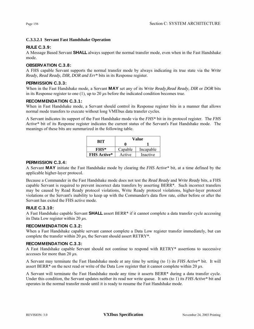
Page 156 Section C: SYSTEM ARCHITECTURE
REVISION: 3.0 VXIbus Specification November 24, 2003 Printing
C.3.3.2.1 Servant Fast Handshake Operation
RULE C.3.9: A Message Based Servant SHALL always support the normal transfer mode, even when in the Fast Handshake mode.
OBSERVATION C.3.8: A FHS capable Servant supports the normal transfer mode by always indicating its true state via the Write Ready, Read Ready, DIR, DOR and Err* bits in its Response register.
PERMISSION C.3.3: When in the Fast Handshake mode, a Servant MAY set any of its Write Ready,Read Ready, DIR or DOR bits in its Response register to one (1), up to 20 µs before the indicated condition becomes true.
RECOMMENDATION C.3.1: When in Fast Handshake mode, a Servant should control its Response register bits in a manner that allows normal mode transfers to execute without long VMEbus data transfer cycles.
A Servant indicates its support of the Fast Handshake mode via the FHS* bit in its protocol register. The FHS Active* bit of its Response register indicates the current status of the Servant's Fast Handshake mode. The meanings of these bits are summarized in the following table.
Value BIT 0 1 FHS* Capable Incapable
FHS Active* Active Inactive
PERMISSION C.3.4: A Servant MAY initiate the Fast Handshake mode by clearing the FHS Active* bit, at a time defined by the applicable higher-layer protocol.
Because a Commander in the Fast Handshake mode does not test the Read Ready and Write Ready bits, a FHS capable Servant is required to prevent incorrect data transfers by asserting BERR*. Such incorrect transfers may be caused by Read Ready protocol violations, Write Ready protocol violations, higher-layer protocol violations or the Servant's inability to keep up with the Commander's data flow rate, either before or after the Servant has exited the FHS active mode.
RULE C.3.10: A Fast Handshake capable Servant SHALL assert BERR* if it cannot complete a data transfer cycle accessing its Data Low register within 20 µs.
RECOMMENDATION C.3.2: When a Fast Handshake capable servant cannot complete a Data Low register transfer immediately, but can complete the transfer within 20 µs, the Servant should assert RETRY*.
RECOMMENDATION C.3.3: A Fast Handshake capable Servant should not continue to respond with RETRY* assertions to successive accesses for more than 20 µs.
A Servant may terminate the Fast Handshake mode at any time by setting (to 1) its FHS Active* bit. It will assert BERR* on the next read or write of the Data Low register that it cannot complete within 20 µs.
A Servant will terminate the Fast Handshake mode any time it asserts BERR* during a data transfer cycle. Under this condition, the Servant updates neither its read nor write queue. It sets (to 1) its FHS Active* bit and operates in the normal transfer mode until it is ready to resume the Fast Handshake mode.

Section C: SYSTEM ARCHITECTURE Page 157
November 24, 2003 Printing VXIbus Specification REVISION: 3.0
C.3.3.2.2 Commander Fast Handshake Operation
The Fast Handshake mode is optional for Commanders, since the normal transfer mode always functions properly. This is true even if its Servant is in the Fast Handshake mode, because its Response register indications are always correct.
A Commander that supports the Fast Handshake mode may execute Fast Handshake transfers only with Servants that are capable of Fast Handshake transfers and which have the Fast Handshake mode active.
RULE C.3.11: A Commander SHALL NOT attempt Fast Handshake mode operations with a Servant having the FHS* bit of its protocol register set (to one).
RULE C.3.12: A Commander SHALL NOT attempt Fast Handshake operations with a Servant while the Servant's FHS Active* bit is set (to 1). A Commander may begin Fast Handshake transfers with a capable Servant only as provided for by the operating higher-layer protocol (provided that the Servant's FHS Active* bit is asserted (0)). It may exit the fast handshake mode at any time. However, it must exit the Fast Handshake mode after any data transfer attempt that results in a bus error or at any other time defined by the higher-layer protocol. The Fast Handshake mode must not be resumed until the Servant again clears (to 0) its FHS* Active bit.
RULE C.3.13: IF a word serial data transfer attempt to a Fast Handshake capable Servant results in the assertion of BERR*, THEN the Commander SHALL NOT attempt any Fast Handshake transfers with the same Servant until that Servant clears (to 0) its FHS Active* bit.
OBSERVATION C.3.9: No data is transferred during a cycle that causes a bus error. The failed transfer should be retried.
OBSERVATION C.3.10: Once a Commander detects a Servant in the Fast Handshake active condition, it does not need to check the Servant's Read Ready, Write Ready, DIR, DOR, Err* or FHS Active* bits again until the Commander exits the Fast Handshake mode. C.3.3.3 WORD SERIAL DATA TRANSFER PROTOCOLS
Word serial commands can be used to transfer data between commanders and their servants. The Byte Transfer Protocol is described in this specification. Other data transfer protocols may also be defined. Word serial data transfer protocols operate by a commander sending commands and queries to its servant. Data sent to the servant is embedded in the commands. Data from Servants is sent in response to queries. It is possible to define protocols that do not require that data sent to servants be embedded in commands or that data from servants be sent only in response to queries. However, such protocols are not allowed to interfere with a servant device's ability to receive normal Word Serial commands and queries. A servant device may support multiple data transfer protocols. Generally, only data transfer protocol may be active at any one time.
Data flow can be regulated by the DIR and DOR bits of the servant's response register. The DIR bit indicates that the servant is ready to accept data from the commander. The DOR bit indicates that the servant has data available for the commander. These bits may be used by multiple data transfer protocols.

Page 158 Section C: SYSTEM ARCHITECTURE
REVISION: 3.0 VXIbus Specification November 24, 2003 Printing
RULE C.3.14: A servant device SHALL NOT implement a data transfer mode that prevents that device from correctly processing normal word serial commands.
OBSERVATION C.3.11: An example of a mode prohibited by the preceding rule is one in which all Word Serial commands are interpreted as data. A device in this mode would be unable to respond to commands such as Clear. C.3.3.3.1 Byte Transfer Protocol
The Byte Transfer Protocol is a mechanism for transferring 8-bit data between Commanders and their Servants. It utilizes the word serial Byte Available and Byte Request commands. The Byte Available command is used to transfer data from a Commander to its Servant. The Byte Request command is used to transfer data from a Servant to its Commander. The data flow is regulated by the use of the DIR and DOR bits in the Servant's Response register.
RULE C.3.15: When a Message Based Servant using the Byte Transfer Protocol is not ready to process a Byte Available command it SHALL clear to zero (0) the DIR bit in its Response register.
OBSERVATION C.3.12: When a Message Based Servant using the Byte Transfer Protocol is ready to process a Byte Available command it will set to one (1) the DIR bit in its Response register.
RULE C.3.16: When a Message Based Servant using the Byte Transfer Protocol is not ready to process a Byte Request command, it SHALL clear to zero (0) the DOR bit in its Response register.
OBSERVATION C.3.13: When a Message Based Servant using the Byte Transfer Protocol is ready to process a Byte Request command, it will set to one (1) the DOR bit in its Response register.
RULE C.3.17: IF a word serial command to a Message Based Servant using the Byte Transfer Protocol causes the unassertion of the DIR bit, THEN the Write Ready bit SHALL NOT be set to one (1) until the DIR bit is cleared to zero (0).
RULE C.3.18: IF a word serial command to a Message Based Servant using the Byte Transfer Protocol causes the de-assertion of the DOR bit, THEN the Write Ready bit SHALL NOT be set to one (1) until the DOR bit is cleared to zero (0).
RULE C.3.19: A Servant using the Byte Transfer Protocol SHALL NOT clear (to 0) either its DIR or DOR bit while its Write Ready bit is set (to 1).
RULE C.3.20: A Commander executing the Byte Transfer Protocol with a Servant SHALL NOT send a Byte Available command to that Servant while its DIR bit is cleared to zero (0).
RULE C.3.21: A Commander executing the Byte Transfer Protocol with a Servant SHALL NOT send a Byte Request command to that Servant while its DOR bit is cleared to zero (0).

Section C: SYSTEM ARCHITECTURE Page 159
November 24, 2003 Printing VXIbus Specification REVISION: 3.0
C.3.3.3.1.1 FAST HANDSHAKE SUPPORT
The Byte Transfer Protocol may be executed using the Fast Handshake protocol. Both the Byte Available and the Byte Request commands are FHS commands, which may utilize the Fast Handshake protocol.
RULE C.3.22: A Servant using the Byte Transfer protocol and the Fast Handshake protocol SHALL support Fast Handshake transfers of both the Byte Available and Byte Request commands. C.3.3.3.1.1.1 Byte Available
The FHS protocol may be used to transfer a message using a series of Byte Available commands. A Servant capable of receiving Byte Available commands in the Fast Handshake mode may enter the FHS Active state (and assert its FHS Active* bit) if it is ready to receive Byte Available commands using the Fast Handshake protocol.
A Commander may begin using Fast Handshake transfers to send Byte Available commands to a Servant if the Servant's Write Ready, DIR and ERR* bits are set to one and the FHS Active* bit is asserted (0).
RULE C.3.23: A Commander SHALL NOT begin Fast Handshake transfers of Byte Available commands to a Servant if that Servant's DIR bit is zero (0) or its Write Ready bit is zero (0) or its Err* bit is zero (0) or its FHS Active* bit is one (1).
RULE C.3.24: A Commander using Fast Handshake to transfer Byte Available commands to a Servant SHALL exit the Fast Handshake mode before sending any command other than Byte Available to that Servant.
OBSERVATION C.3.14: A Commander is required to exit the Fast Handshake mode when a read or write of the Servant's Data Low register results in a bus error.
The END bit of the Byte Available command is used to indicate the end of a message. This may cause a servant to exit the Fast Handshake Active state. If the commander also exits the Fast Handshake mode, it can avoid a bus error.
RECOMMENDATION C.3.4: A Commander should exit the Fast Handshake mode after sending a Byte Available command having the END bit asserted.
RULE C.3.25: When its Commander writes a Byte Available to a Servant capable of receiving Byte Available commands in the Fast Handshake mode and the Servant's DIR bit is zero, the Servant SHALL assert BERR* without changing the state of any of its Read Ready, Write Ready, DIR, DOR or Err* bits. C.3.3.3.1.1.2 Byte Request
The FHS protocol may be used to transfer a message using a series of Byte Request commands. A Servant capable of receiving Byte Request commands in the Fast Handshake mode may enter the FHS Active state (and assert its FHS Active* bit) if it is ready to receive Byte Request commands using the Fast Handshake protocol.
A Commander may begin using Fast Handshake transfers to send Byte Request commands to a Servant if the Servant's Write Ready, DOR and ERR* bits are set to one and the FHS Active* bit is asserted (0).

Page 160 Section C: SYSTEM ARCHITECTURE
REVISION: 3.0 VXIbus Specification November 24, 2003 Printing
RULE C.3.26: A Commander SHALL NOT begin Fast Handshake transfers of Byte Request commands to a Servant if that Servant's DOR bit is zero (0) or its Write Ready bit is zero (0) or its Err* bit is zero (0) or its FHS Active* bit is one (1).
RULE C.3.27: A Commander using Fast Handshake to transfer Byte Request commands to a Servant SHALL exit the Fast Handshake mode before sending any command other than Byte Request to that Servant.
OBSERVATION C.3.15: A Commander is required to exit the Fast Handshake mode when a read or write of the Servant's Data Low register results in a bus error.
The END bit of the response to a Byte Request command is used to indicate the end of a message. This may cause a servant to exit the Fast Handshake Active state. If the commander also exits the Fast Handshake mode, it can avoid a bus error.
RECOMMENDATION C.3.5: A Commander should exit the Fast Handshake mode after reading a response to a Byte Request command if the END bit of the response is asserted.
RULE C.3.28: When its Commander writes a Byte Request to a Servant capable of receiving Byte Request commands in the Fast Handshake mode and the Servant's DOR bit is zero, the Servant SHALL assert BERR* without changing the state of any of its Read Ready, Write Ready, DIR, DOR or Err* bits. C.3.3.4 ERROR HANDLING
VXIbus Message Based Devices implement a uniform method of reporting word serial protocol errors. It is a multi-level approach wherein all word serial protocol conformance errors are reported via the Err* bit in the Response register and the Read Protocol Error command. Higher level errors are reported at higher levels, often as status responses to commands.
There are six defined word serial protocol errors:
• Unsupported Command: This error is detected when a Servant receives a command which it does not support.
• Multiple Query: This error occurs when a Servant receives a command requiring it to output a response to its Data Low register and is unable to respond because of an unread response to a previous command.
• DIR Violation: This error occurs when a Servant receives a Byte Available command when it is unable to process that command because the DIR bit is zero (0).
• DOR Violation: This error occurs when a Servant receives a Byte Request command when it is unable to process that command because the DOR bit is zero (0).
• Write Ready Violation: This error occurs when data is written to a Servant while its Write Ready bit is zero (0).
• Read Ready Violation: This error occurs when data is read from a Servant while its Read Ready bit is zero (0).

Section C: SYSTEM ARCHITECTURE Page 161
November 24, 2003 Printing VXIbus Specification REVISION: 3.0
RULE C.3.29: A Message Based Device SHALL detect the Unsupported Command, Multiple Query, DIR Violation and DOR Violation errors.
OBSERVATION C.3.16: A Servant may respond to a Read Ready or Write Ready protocol violation by either asserting BERR*, asserting its Err* bit or not detecting the violation.
OBSERVATION C.3.17: A Fast Handshake capable Servant prevents incorrect data transfers due to DIR and DOR violations by asserting RETRY* or BERR*.
RULE C.3.30: IF a command to a Message Based Device causes the detection of one of the defined word serial protocol errors, THEN the device SHALL NOT execute that command.
RULE C.3.31: IF a command to a Message Based Device causes the detection of one of the defined word serial protocol errors which does not result in a bus error, THEN the Servant SHALL clear both the Err* and Read Ready bits. The Write Ready bit SHALL NOT be set to one (1) until both the Err* and Read Ready bits are cleared to zero (0).
RULE C.3.32: Each Message Based Device SHALL maintain its Current Error State (which is reported via the Read Protocol Error command) as follows:
1. The current error state is set to No error by a HARD RESET, SOFT RESET or receipt of the Clear command.
2. The current error state is set to No error when the device responds to the End Normal Operation or the Abort Normal Operation command.
3. The current error state is set to No error after the device responds to the Read Protocol Error command.
4. When a word serial protocol error is detected while the device is in the No Error state, the current error state is set to reference that error. Subsequent errors SHALL NOT cause updates to the error state.
RULE C.3.33: When a Message Based Servant receives the Read Protocol Error command, it SHALL set its Err* bit to one (1) before it sets its Write Ready bit to one (1).
OBSERVATION C.3.18: A Commander that implements rigorous error checking will test for errors after writing each command as follows:
1. Wait for the Write Ready bit to be asserted.
2. Test the Err* bit.
3. If no error is indicated, then read the response data (when Read Ready is asserted) or send the next command. Otherwise, send Read Protocol Error and read its response.

Page 162 Section C: SYSTEM ARCHITECTURE
REVISION: 3.0 VXIbus Specification November 24, 2003 Printing
RECOMMENDATION C.3.6: Commanders and Resource Managers should implement rigorous error checking when communicating with their Servants, especially during system initialization.
RULE C.3.34: When a Message Based Servant receives a command requiring it to output a response to its data low register, it SHALL NOT make the re-assertion of its Write Ready bit contingent on its Commander reading the response data. C.3.3.5 DEVICE FAILURES
When a device experiences a catastrophic failure, it enters the FAILED state, asserting SYSFAIL* and clearing (to 0) its Passed bit.
RULE C.3.35: IF a device is in the FAILED state, THEN that device's Commander SHALL set (to 1) the Sysfail Inhibit bit of the Control register on the failed device.
PERMISSION C.3.5: When a device fails, the device's Commander MAY also set (to 1) the Reset bit of the Control register on the failed device.
OBSERVATION C.3.19: A Commander may detect that a Servant has failed by monitoring the SYSFAIL* signal or polling the Passed bit in the Status register of a device.
RECOMMENDATION C.3.7: When a top level device fails, the Resource Manager should set (to 1) the Sysfail Inhibit bit of the Control register on the failed device.

Section C: SYSTEM ARCHITECTURE Page 163
November 24, 2003 Printing VXIbus Specification REVISION: 3.0
C.4 SYSTEM RESOURCES
The VXIbus architecture provides for a set of common system resources. These include Slot 0 services and system configuration management. This section describes how these services are provided. The configuration management services are provided by a central Resource Manager and Slot 0 services are either provided by the Resource Manager or by Slot 0 devices. C.4.1 Resource Manager
The VXIbus Resource Manager is a device at Logical Address 0 that performs the following functions at system power-on.
1. Identify all VXIbus devices in the system.
2. Manage the system self test and diagnostic sequence.
3. Configure the system's A24, A32 and A64 address maps.
4. Configure the system's Commander/Servant hierarchies.
5. Allocate the VMEbus IRQ lines.
6. Initiate normal system operation.
The logical addresses of VXIbus devices can be statically set or dynamically assigned. In this section, the Resource Manager's functions in the case of statically set logical addresses are described. The functions for dynamic assignment of logical addresses are described in Section F, "Dynamic Configuration".
RULE C.4.1: A Resource Manager SHALL be a Message Based Device with Commander capability.
PERMISSION C.4.1: The functions of a Resource Manager MAY be combined with those of another Message Based Commander.
OBSERVATION C.4.1: If a Resource Manager is combined with other Message Based functionality, the Resource Manager configures its Message Based functions as it would any other Message Based Device. In this case it uses device specific internal communications, instead of word serial commands.
RULE C.4.2 IF a Resource Manager device is not configured as a top level Commander, THEN it SHALL behave as a normal Message Based Device toward its Commander and Servants.
RULE C.4.3: A Resource Manager SHALL provide a device specific mechanism for reporting system configuration errors.
PERMISSION C.4.2: A Resource Manager MAY provide Slot 0 services in addition to its other duties.
RULE C.4.4: A Resource Manager which lacks device specific knowledge of a device SHALL write a one (1) to all the device dependent bits in the Control register whenever it writes to the Control register of that device.
OBSERVATION C.4.2: A Resource Manager will normally write to the Control register of a device to affect the A24/A32/A64 Enable, Sysfail Inhibit or Reset bits.

Page 164 Section C: SYSTEM ARCHITECTURE
REVISION: 3.0 VXIbus Specification November 24, 2003 Printing
C.4.1.1 DEVICE IDENTIFICATION
The Resource Manager identifies the available VXIbus devices according to the following procedure.
RULE C.4.5: All Resource Managers SHALL implement the following device identification procedure.
1. After the unassertion of SYSRESET*, wait until either SYSFAIL* is unasserted or five seconds (5.0 s) have elapsed (whichever occurs first) before accessing any other VXIbus device's A16 configuration registers.
2. Attempt a read of the Status register at each of the 256 defined configuration register locations. If an attempt is successful, the corresponding device is present. If a bus error results, the device is absent.
OBSERVATION C.4.3: Local VMEbus operations that do not access any of the registers of VXIbus devices are permitted before the unassertion of SYSFAIL* or the five (5) second timeout. C.4.1.2 SYSTEM SELF TEST MANAGEMENT
RULE C.4.6: All Resource Managers SHALL implement the following self test management procedure.
1. Wait until all self tests have completed.
2. Force all failed devices into the SOFT RESET state with SYSFAIL* assertion inhibited (see Section C.2.1.2, "Device Initialization and Diagnostics").
OBSERVATION C.4.4: A device has completed its self test when its Passed bit is one (1) or when at least five seconds after power-on (Unassertion of SYSRESET*) have elapsed.
OBSERVATION C.4.5: The Resource Manager forces a device into its SOFT RESET state by writing a one to the device's Reset bit.
OBSERVATION C.4.6: The Resource Manager causes a device to inhibit SYSFAIL* assertion by writing a one to the device's Sysfail Inhibit bit.
PERMISSION C.4.3: A Resource Manager MAY perform diagnostic tests of a failed device by some device dependent method.
PERMISSION C.4.4: A Resource Manager MAY implement the capability to detect the subsequent failure of a device that has passed its initial self test.
RULE C.4.7: When the Resource Manager detects that a device has failed sometime after the initial five seconds but before the Resource Manager has sent the Begin Normal Operation command to that device's top-level Commander, the Resource Manager SHALL force the failed device into the SOFT RESET state with SYSFAIL* assertion inhibited.

Section C: SYSTEM ARCHITECTURE Page 165
November 24, 2003 Printing VXIbus Specification REVISION: 3.0
C.4.1.3 ADDRESS MAP CONFIGURATION
RULE C.4.8: All Resource Managers SHALL implement the following A24, A32 and A64 address map configuration procedure:
1. Determine which devices implement A24, A32 or A64 registers by reading the Address Space field of each device's ID register and the Address Mode field of the Enhanced Capabilities register, if appropriate.
2. Determine the number of A24, A32 or A64 registers implemented by each device by reading the Required Memory field of the device's Device Type register.
3. Calculate A24, A32 and A64 offsets such that no two device's address spaces overlap.
4. Assign the A24, A32 and A64 base addresses by writing the offsets to each device's Offset register.
5. Enable each device's A24, A32 or A64 registers by writing a one (1) to the A24/A32/A64 Enable bit of each device's Control register.
RECOMMENDATION C.4.1: All A24 base address offsets should be assigned so that the registers are placed within the address range 20000016 through DFFFFF16. All A32 base address offsets should be assigned so that the registers are placed within the address range 2000000016 through DFFFFFFF16.
RECOMMENDATION C.4.2: For compatibility with possible future versions of the VXIbus Specification, Resource Managers should be designed to properly configure any A16 Only, A16/A24 or A16/32 device that implements an Enhanced Capability register. Such a device would have the value 102 in the Address Space field of its ID register. In this case, a Resource Manager should use the value in the Address Mode field of the Enhanced Capability register to determine the address modes used by the device, according to the following table:
Value Mode 000 A16/A24 001 A16/A32 011 A16 Only
OBSERVATION C.4.7: All A16 Only, A16/A24 and A16/A32 devices are now required to report their addressing modes in the Address Space field of the ID register. Future versions of the VXIbus Specification may define additional capabilities that would be indicated in the Enhanced Capability register. An A16 Only, A16/A24 or A16/A32 device that implements such capabilities would have the value 102 in the Address Space field of its ID register. Its addressing modes would then have to be reported in the Address Mode field of its Enhanced Capabilities register. The preceding recommendation anticipates this situation. C.4.1.4 COMMANDER/SERVANT HIERARCHIES
The Resource Manager establishes a system wide control hierarchy. This structure has the form of one or more inverted trees. The hierarchical relationships are described by the terms Commander and Servant. A Commander is any device in the hierarchy with one or more associated lower level devices. A Servant is any device in the subtree of a Commander. A device may be both a Commander and a Servant in a multiple level hierarchy. A Commander has exclusive control of his immediate Servants' communication and control registers. A top level Commander has no Commander but may have Servants. All Commanders are Message Based Devices.
A Resource Manager establishes the system hierarchy in the following manner.
1. Find all Commanders by checking the CMDR bit in the protocol register of each Message Based Device.
2. Read the Servant Area Size from each Commander, using the Read Servant Area query.

Page 166 Section C: SYSTEM ARCHITECTURE
REVISION: 3.0 VXIbus Specification November 24, 2003 Printing
3. Determine the Commander/Servant hierarchies.
4. Assign Servants to Commanders, using the grant device command.
RULE C.4.9: A Resource Manager SHALL implement some means of building a Commander/Servant hierarchy.
RECOMMENDATION C.4.3: A Resource Manager should implement the default Commander/Servant mapping algorithm described in the following section.
OBSERVATION C.4.8: Each Commander maintains a list of its Servants, received via the grant device command. It maintains this list until the next activation of HARD RESET or SOFT RESET or the receipt of the Abort Normal Operation command.
RULE C.4.10: A Resource Manager SHALL NOT grant to any Commander a device which the Resource Manager knows to be in any state other than PASSED. (see Section C.2.1.2.2, "Self Test Operation").
OBSERVATION C.4.9: It cannot be assured that the Resource Manager will detect any device failures after the initial self test. C.4.1.4.1 Commander/Servant Mapping
The default Commander/Servant mapping algorithm allows for a virtually unlimited number of hierarchical levels. It is based on each VXIbus device's Logical Addresses and each Commander's Servant are A-sized. The Servant are A-size is an 8-bit (0-255) value selected by the user or at the factory. It is stored in a non-volatile fashion in each Commander device.
A Commander's Servant area starts at the next consecutive Logical Address after the Commander's logical address and includes the number of contiguous Logical Addresses given by the Commander's Servant are A-size.
If a device is in the Servant area of a given Commander and it is not in the Servant area of any other device within that Commander's Servant area, then it is a Servant of that Commander and may be assigned to that Commander by the Resource Manager.
OBSERVATION C.4.10: All of a device's default Servants are in its own Servant area.
OBSERVATION C.4.11: A device's Servant area may include the Servant areas of its Servants.
OBSERVATION C.4.12: None of a device's Servants are located in any of the Servant areas of its Servants. C.4.1.5 ALLOCATION IRQ LINES
The Resource Manager is responsible for allocating the VMEbus IRQ lines among the various Interrupt Handlers and Interrupters in the system. Each IRQ line may be assigned to only one handler, but to several Interrupters. Provision must be made for devices with jumper selectable IRQ line assignments as well as for programmable Interrupters and Interrupt Handlers. This requires that some interrupt configuration information be supplied by the system user.
RULE C.4.11: A Resource Manager SHALL provide a means for a user to supply interrupt configuration information relating Interrupt Handlers and Interrupters to any or all interrupt lines.

Section C: SYSTEM ARCHITECTURE Page 167
November 24, 2003 Printing VXIbus Specification REVISION: 3.0
OBSERVATION C.4.13: The form of the interrupt configuration information is device dependent. It is anticipated that the information will typically be loaded from a system console, downloaded from a host computer or retrieved from some form of non-volatile storage.
RULE C.4.12: A Resource Manager SHALL allocate IRQ lines to Interrupt Handlers according to the following procedure.
1. Determine which Message Based Devices support Programmable Interrupt Handler (PH) capability (using the Read Protocol command).
2. Allocate the IRQ lines according to the following rules:
a. First use the supplied interrupt allocation information.
b. Then allocate one of the remaining IRQ lines to each PH capable Commander, in any desired order.
c. Finally allocate any remaining IRQ lines to any Servant-only PH capable Message Based Devices, and any PH Commanders indicating multiple handler capability.
3. For each Programmable Handler assigned an IRQ line, program its IRQ allocation, using the Read Handlers, Read Handler Line and Assign Handler Line commands.
RULE C.4.13: A Resource Manager SHALL allocate IRQ lines to Interrupters according to the following procedure.
1. Determine which Message Based Servants have Programmable Interrupter (PI) capability, using the Read Protocol command.
2. Allocate the IRQ lines according to the following rules:
a. First use the supplied interrupt allocation information.
b. Then allocate an IRQ line to each PI capable Servant, based on its Commander's IRQ line allocation.
3. For each Programmable Interrupter assigned an IRQ line, program its IRQ allocation, using the Read Interrupters, Read Interrupter Line and Assign Interrupter Line commands.
C.4.1.6 INITIATING NORMAL OPERATION
After allocating IRQ lines, a Resource Manager may provide some system dependent start-up services. It then sends the Begin Normal Operation command, with the Top Level bit set (to one (1)), to all top level Commanders in order of increasing logical address. At this point the Resource Manager's power-on sequence is complete and it may enter its run time operating mode.
Each top level Commander is then required to initialize its Servants. Each Commander must send the Begin Normal Operation command, with the Top Level bit cleared (to zero (0)), to all of its Message Based Servants. Therefore, the Begin Normal Operation command propagates down the hierarchy from Commanders to Servants, until all Message Based Devices have received it.
RULE C.4.14: A Resource Manager SHALL NOT change the configuration or state of any other device's Servant from its power-on default conditions, except as required to perform the system self test management, address map configuration, commander/servant mapping, IRQ line allocation and dynamic Logical Address assignment.
OBSERVATION C.4.14: When a Commander receives the Begin Normal Operation command, its Message Based Servants are in the CONFIGURE sub-state with any Response and Event generation capabilities set according to the default configuration defined in Rule C.2.78.

Page 168 Section C: SYSTEM ARCHITECTURE
REVISION: 3.0 VXIbus Specification November 24, 2003 Printing
C.4.2 Runtime Resource Management
In Section C.4.1, "Resource Manager" and in Section F, "Dynamic Configuration", resource management is defined only for default configuration. The behavior of a Resource Manager which provides ongoing services for a device in NORMAL OPERATION sub-state has not been defined. Ongoing resource management services can be used to support shared resource utilization or other system operations. In the following, the term "runtime resource management" is used for such ongoing resource management.
PERMISSION C.4.5: A Resource Manager which handles default system configuration as described in Section C.4.1, "Resource Manager" (and in section F, "Dynamic Configuration") MAY handle runtime resource management.
OBSERVATION C.4.15: It is a violation of the Word Serial Protocol for a device involved in runtime resource management to send any word serial command (including End Normal Operation and Abort Normal Operation) to any device while that device's Commander is in the NORMAL OPERATION sub-state.
C.4.3 VXIbus Subsystem Slot 0
A VXIbus Slot 0 device provides common resources to its VXIbus subsystem slots 1-12. On P2, the resources provided are CLK10 and MODID. On P3, the Slot 0 device provides CLK100. It may also provide SYNC100, STARX and STARY signal distribution on P3.
OBSERVATION C.4.16: VXIbus Slot 0 devices exist only on B, C and D form factors.
RULE C.4.15: All Slot 0 devices SHALL supply CLK10.
RULE C.4.16: All Slot 0 devices SHALL support MODID.
RULE C.4.17: All P3 Slot 0 devices SHALL provide CLK100.
OBSERVATION C.4.17: SYNC100, STARX and STARY are not required to be supported by Slot 0 devices.
RECOMMENDATION C.4.4: If only one STAR signal set is provided, it should be STARX.
RECOMMENDATION C.4.5: IF a Slot 0 device supports either STAR signal set THEN it should support a contiguous set of slots including slot 1.
OBSERVATION C.4.18: A Slot 0 device is only guaranteed to provide CLK10 and MODID support. It may also provide other services such as SYNC100 arbitration, trigger line buffering and STARX and STARY routing.
A Slot 0 device may be identified by its Model Code, which has a value in the range 0 → 255 (016 → FF16).
RULE C.4.18: All VXIbus Slot 0 devices SHALL have model codes in the range 016 → FF16.
RULE C.4.19: A VXIbus device which is not enabled for Slot 0 functionality SHALL NOT have a model code in the range 016 → FF16. A Slot 0 device with its Slot 0 functions disabled (via switches, jumpers, cut traces, etc) SHALL also have its Model Code modified to some value outside the range 016 → FF16.

Section C: SYSTEM ARCHITECTURE Page 169
November 24, 2003 Printing VXIbus Specification REVISION: 3.0
RECOMMENDATION C.4.6: A Slot 0 module's Slot 0 and VMEbus system controller capability should be defeatable in order to allow that module to be placed in any slot position.
RULE C.4.20: All MODID drivers SHALL be disabled by both hard and soft resets (See Section C.2.1.2.2, "Self Test Operation"). C.4.3.1 REGISTER BASED SLOT 0 DEVICES
A Register Based Slot 0 Device is a standard VXIbus Register Based Device that supports Slot 0 functionality. Its Model Code (in its Device Type register - See Section C.2.1.1.2, "Configuration Registers") is in the range 0 → 255 (016 → FF16) and it has a MODID register at its A16 base address + 816. It may implement additional Slot 0 related registers.
RULE C.4.21: A Register Based VXIbus Slot 0 Device SHALL implement a MODID register as defined in the following section (C.4.3.1.1) at its A16 base address + 816.
PERMISSION C.4.6: The remaining device dependent registers MAY be used to implement other Slot 0 related services. C.4.3.1.1 MODID Register
The MODID register indicates the status of and provides control of the associated MODID lines. It conforms to the following format.
Bit # 15 ← 14 13 12 ← 0
Contents RESERVED Output Enable MODID00-12
The fields of the MODID register are defined below. • RESERVED: This field is reserved for future VXIbus definition. A write to this field has no effect. A
read of this field returns all ones (316).
• Output Enable: Writing a one (1) to this bit enables the Slot 0 MODID drivers. Writing a zero (0) to this bit disables the MODID drivers. A one (1) read from this bit indicates that the MODID drivers are enabled. A zero (0) indicates that the drivers are disabled.
OBSERVATION C.4.19: All MODID drivers are disabled by device resets (The Output Enable bit is cleared (to 0)).
• MODID 00-12: Writing a one (1) to any of these bits drives the corresponding MODID line high, if the Output Enable bit is set. Writing a zero (0) to any of these bits drives the corresponding line low, if the Output Enable bit is set. When read, each of these bits indicates the actual level of the corresponding MODID line (1 = HI, 0 = LOW).
OBSERVATION C.4.20: After system power up, the bit values of MODID00-12 in the MODID write register may be undefined.
Page 170 Section C: SYSTEM ARCHITECTURE
REVISION: 3.0 VXIbus Specification November 24, 2003 Printing
C.4.3.2 MESSAGE BASED SLOT 0 DEVICES
A Message Based Slot 0 Device is a standard VXIbus Message Based Device that supports Slot 0 functionality. Its Model Code (in its Device Type register - See Section C.2.1.1.2, "Configuration Registers") is in the range 0 → 255 and it supports the MODID related commands. It may implement additional Slot 0 related commands.
RULE C.4.22: A Message Based VXIbus Slot 0 Device SHALL implement the Read MODID, Set Lower MODID and Set Upper MODID commands as defined in Section E.1, "Word Serial Commands".
PERMISSION C.4.7: A Message Based Slot 0 Device MAY implement commands to provide other Slot 0 related services.
The MODID related commands are used to indicate the status of the MODID lines and to control the levels of the MODID lines.
OBSERVATION C.4.21: All MODID drivers are disabled by device resets. C.4.3.3 OTHER SLOT 0 DEVICES
Since VXIbus only requires support of MODID and CLK10 lines from a Slot 0 device, the Resource Manager may provide the Slot 0 services in addition to its other functions. This arrangement hides the Slot 0 functionality inside the Resource Manager and therefore allows another device to provide Slot 0 functionality without using a Logical Address for a minimal Slot 0 implementation.

Section D: VXIbus DEVICE IMPLEMENTATIONS Page 171
November 24, 2003 Printing VXIbus Specification REVISION: 3.0
D. VXIbus DEVICE IMPLEMENTATIONS
This section describes the design rules for certain devices which facilitate manufacturer to manufacturer interchangeability. The protocols are defined at a higher level than defined by the system architecture. These protocols, along with the common command formats, are specified in the following sections. One common device is a VXIbus to IEEE 488 bus [3] interface. This device allows VXIbus devices to be controlled via the 488 bus as if they are 488 devices. The following sections define such an interface, its VXIbus protocols and the requirements for an instrument to interface to it. The protocols are intended to be extensible to other interfaces and Commanders. D.1 VXIbus INSTRUMENTS
This section specifies the interfacing requirements for VXIbus Instruments. These are devices which may be controlled with the VXIbus Instrument Protocol, implemented by a VXIbus Interface Device. D.1.1 VXIbus Instrument Protocols
RULE D.1.1:
A VXIbus instrument SHALL be a Message Based Device and provide the VXIbus word serial communication protocol.
VXIbus instruments communicate with the core set of commands and events described in the following sections.
OBSERVATION D.1.1:
The following commands are considered to be Instrument Protocol commands:
• Byte Available
• Byte Request
• Clear
• Trigger
• Set Lock
• Clear Lock
• Read STB
The Byte Transfer Protocol is used to communicate with VXIbus instruments. Other protocols may also be used.
RULE D.1.2: VXIbus Instruments SHALL support the Byte Transfer Protocol.
PERMISSION D.1.1: VXIbus Instruments MAY support other Word Serial data transfer protocols.
RULE D.1.3: A VXIbus instrument SHALL NOT have more than one Word Serial data transfer protocol active at a time.
RULE D.1.4: When a VXIbus Instrument enters the Normal Operation State, it SHALL become enabled for the Byte Transfer Protocol.

Page 172 Section D: VXIbus DEVICE IMPLEMENTATIONS
REVISION: 3.0 VXIbus Specification November 24, 2003 Printing
D.1.1.1 DATA TRANSFER from COMMANDERS to INSTRUMENTS
The Byte Available command is used to send a data byte (DAB) to a VXIbus instrument. The command includes an END bit which may be used as a message terminator.
RULE D.1.5: All VXIbus instruments SHALL support the Byte Available command in conformance to the Byte Transfer Protocol.
OBSERVATION D.1.2: The Byte Transfer Protocol provides for an instrument to hold off incoming Byte Available commands while still allowing other commands such as Clear and Read STB.
OBSERVATION D.1.3: The state of DIR when the Write Ready bit becomes asserted allows a Commander to determine whether or not to send a Byte Available or Trigger command to the Servant. If DIR is set, then the Commander may send a Byte Available or Trigger command. D.1.1.2 DATA TRANSFER from INSTRUMENTS to COMMANDERS
Data transfer from an instrument to its Commander is initiated by the Commander by sending a Byte Request command to the VXIbus instrument. The instrument responds by making the data byte available in its data registers. The returned data includes an END bit which may be used as a message terminator.
RULE C.1.6: All VXIbus instruments SHALL support the Byte Request command in conformance to the Byte Transfer Protocol.
OBSERVATION D.1.4: The Byte Transfer Protocol provides for an instrument to indicate the presence of data in its output buffer (thus readiness for a Byte Request command).
OBSERVATION D.1.5: The state of DOR when the Write Ready bit becomes asserted allows a Commander to determine whether or not to send a Byte Request command to the Servant. If DOR is set, then the Commander can send the Byte Request command. D.1.1.3 CLEARING a VXIbus INSTRUMENT
A VXIbus instrument which receives a Clear command will respond according to the following rules (in addition to Rules C.2.100 and C.2.101).
RULE D.1.7: Upon receipt of the Clear command the VXIbus instrument SHALL perform the following actions:
• clear its input buffer (set DIR)
• clear its output queue (clear DOR, if appropriate)
• become ready to process new commands
Further clarification of the proper operation of the Clear command may be found in the IEEE 488.2 Standard [4], Section 5.8, "Device Clear Requirements".

Section D: VXIbus DEVICE IMPLEMENTATIONS Page 173
November 24, 2003 Printing VXIbus Specification REVISION: 3.0
OBSERVATION D.1.6: The VXIbus Clear command may affect current instrument operation for VXIbus instruments, while for VXIbus IEEE 488.2 instruments it will not.
RULE D.1.8: All VXIbus instruments SHALL support the Clear command.
RULE D.1.9: In response to a Clear command, a VXIbus instrument that supports multiple Word Serial data transfer protocols SHALL NOT disable the currently active data transfer protocol or enable another data transfer protocol. D.1.1.4 TRIGGERING an INSTRUMENT
RULE D.1.10: All VXIbus instruments which support a trigger function SHALL be capable of being triggered via the Trigger command.
PERMISSION D.1.2: VXIbus Instruments may support other methods of triggering (i.e. P2 or P3 hardware trigger busses).
RULE D.1.11: When a VXIbus instrument is not ready to process a Trigger command it SHALL clear to zero (0) the DIR bit in its Response register.
OBSERVATION D.1.7: When a VXIbus instrument is ready to process a Trigger command it will normally set to one (1) the DIR bit in its Response register. D.1.1.5 LOCAL LOCKOUT
A Commander can issue the Set Lock command to its Servant if it wishes the Servant to ignore commands from local sources. The Clear Lock command is used by a Commander to cause a device to exit the Lock state.
RULE D.1.12: IF an instrument supports the Set Lock command, THEN upon receipt of the Set lock command it SHALL clear (to zero (0)) the Locked* bit (bit 7) in its Response register.
RULE D.1.13: IF an instrument supports the Clear Lock command, THEN upon receipt of the Clear lock command it SHALL set (to one (1)) the Locked* bit (bit 7) in its Response register.
RULE D.1.14 IF an instrument supports the Set Lock command, THEN local control of the device SHALL be disabled upon the receipt of a Set Lock command.
RULE D.1.14 IF an instrument has had local control disabled by the receipt of a Set Lock command, THEN local control of that device SHALL NOT be re-enabled until the receipt of a Clear Lock command.

Page 174 Section D: VXIbus DEVICE IMPLEMENTATIONS
REVISION: 3.0 VXIbus Specification November 24, 2003 Printing
PERMISSION D.1.3: Local operations which do not affect device operations will be allowed while the device is in the locked state as per IEEE 488.2.
PERMISSION D.1.4: VXIbus instruments MAY implement the Set Lock and Clear Lock commands.
RECOMMENDATION D.1.1: If an instrument implements either the Set Lock or the Clear Lock command then it should implement both commands. D.1.1.6 SRQ OPERATION
When a device needs to request service on an interface, it sends a request true event to its Commander. This event can be sent via the event form of the interrupt response word or as a signal. If the need for service is removed, a device which has previously sent a request true event must send the request false event. This event is sent in an analogous manner to the request true event.
PERMISSION D.1.5: VXIbus instruments MAY implement the request true and request false events.
RULE D.1.16: IF a VXIbus Instrument has VMEbus Master capability, THEN the request true and request false events SHALL be sent using signals (unless modified by the Asynchronous Mode Control command).
RULE D.1.17: IF a VXIbus Instrument does not have VMEbus Master capability, THEN the request true and request false events SHALL be sent using interrupts (unless modified by the Asynchronous Mode Control command). D.1.1.7 SPOLL OPERATION
PERMISSION D.1.6: VXIbus instruments MAY implement the Read STB command. RULE D.1.18: A VXIbus instrument which implements the Read STB command SHALL send as bit 6 of its response a bit that is equivalent to the MSS bit of the *STB? response in IEEE Standard 488.2-1987.
OBSERVATION D.1.8: This bit is to indicate whether or not the device is currently requesting service. In an interface other than IEEE 488.1 the RQS function may not be available. In this case, the device indicates its current needs to the requester via this bit. D.1.1.8 ERROR REPORTING
Error reporting is divided into two parts: Word Serial Protocol errors and errors resulting from messages sent via the Byte Available command. Word Serial Protocol error reporting is described in Section C.3.3.4, "Error Handling". Errors which are the result of higher-level messages received via the Byte Available command are reported via the request true event.

Section D: VXIbus DEVICE IMPLEMENTATIONS Page 175
November 24, 2003 Printing VXIbus Specification REVISION: 3.0
RULE D.1.19: IF a device reports errors via signals or interrupts as a result of messages received via the Byte Available command, THEN that device SHALL use the request true event to notify its Commander of the error.
RECOMMENDATION D.1.2: A VXIbus Instrument should follow the IEEE 488.2 error reporting conventions (Reference: IEEE 488.2, Sections 11.3 and 11.5) including the enabling and disabling of the request true event generation. D.1.1.9 INITIALIZATION
VXIbus instruments require no initialization beyond that required for all Message Based Instruments. Once a VXIbus system is configured, the instruments are ready to process Instrument Protocol commands.
RULE D.1.20: After the receipt of the Begin Normal Operation command, a VXIbus Instrument SHALL become ready to accept Instrument protocol commands.
OBSERVATION D.1.9: Normally when a device is ready to accept Instrument protocol commands it will have the following indications: DIR=1, DOR=0, Locked=1, Read Ready=0, Write Ready=1 and Err*=1.
OBSERVATION D.1.10: A device which implements a self initiated trigger, may have data ready for output when it is ready to accept Instrument protocol commands. It will indicate this with DOR=1. D.1.2 VXIbus IEEE-488.2 Instrument Protocols
This section describes additions to the VXIbus Instrument Protocols which apply to VXIbus IEEE-488.2 Instruments.
RULE D.1.21: All VXIbus IEEE-488.2 Instruments SHALL comply with all the rules for VXIbus Instruments. D.1.2.1 CLEARING a VXIbus IEEE-488.2 INSTRUMENT
RULE D.1.22: The Clear command SHALL NOT affect current instrument operation for a VXIbus IEEE-488.2 Instrument.
RULE D.1.23: VXIbus IEEE-488.2 Instruments SHALL implement the Clear command according to the specifications in the IEEE 488.2 Standard, Section 5.8, "Device Clear Requirements". D.1.2.2 TRIGGERING an IEEE-488.2 INSTRUMENT
OBSERVATION D.1.11: VXIbus IEEE 488.2 instruments MAY support either DT0 or DT1 IEEE 488.1 subsets.

Page 176 Section D: VXIbus DEVICE IMPLEMENTATIONS
REVISION: 3.0 VXIbus Specification November 24, 2003 Printing
D.1.2.3 LOCAL LOCKOUT
OBSERVATION D.1.12: VXIbus IEEE 488.2 instruments MAY support either RL0 or RL1 IEEE 488.1 subsets. D.1.2.4 SSRQ OPERATION
RULE D.1.24: All VXIbus IEEE 488.2 instruments SHALL implement the request true and request false events. D.1.2.5 SPOLL OPERATION
RULE D.1.25: All VXIbus IEEE 488.2 instruments SHALL implement all the required 488.2 status reporting registers and protocols and the Read STB command.
OBSERVATION D.1.13: The response to a Read STB command will have a bit 6 which is equivalent to the MSS bit of the STB? response in IEEE Standard 488.2-1987.
Section D: VXIbus DEVICE IMPLEMENTATIONS Page 177
November 24, 2003 Printing VXIbus Specification REVISION: 3.0
D.2 488-VXIbus INTERFACE
The 488-VXIbus interface device converts IEEE 488 protocols to VXIbus instrument control protocols, allowing IEEE 488 external controllers to control VXIbus instruments in a manner analogous to a typical rack and stack instrument system. The primary function of the 488-VXIbus Interface device is to route the IEEE 488 messages to the appropriate VXIbus instrument and to return the results from the instrument to the external IEEE 488 controller. A VXIbus system may or may not provide one or more 488-VXIbus Interface devices.
RULE D.2.1: A 488-VXIbus Interface SHALL be a Message Based Commander.
RULE D.2.2: A 488-VXIbus Interface device SHALL support the receipt of signals.
RULE D.2.3: A 488-VXIbus Interface device SHALL be an Interrupt Handler.
PERMISSION D.2.1: When a 488-VXIbus Interface device detects that a Servant has not recognized a command (error response from the Servant), the interface action is left to the device designer. D.2.1 IEEE 488 Address Mapping
The mapping of an IEEE 488 address to VXIbus Logical Address is a function which is handled by the 488-VXIbus Interface device. The particulars of this mapping are interface device specific. Several potential mappings are described below:
• The 488-VXIbus Interface device supports primary addressing of 31 potential addresses. The 31 IEEE 488 addresses will be associated one for one with 31 Logical Addresses of the VXIbus instruments.
• The 488-VXIbus Interface device supports secondary addressing of 31 potential secondary addresses. The 488-VXIbus Interface device will provide a means of selecting the primary address. The 31 IEEE 488 secondary addresses will be associated one for one with 31 Logical Addresses of the VXIbus instruments.
• The 488-VXIbus Interface device supports a single primary IEEE 488 address through which all VXIbus Instruments are addressed. The particular language constructs which implement routing are up to the interface device designer.
OBSERVATION D.2.1: 488-VXIbus Interface devices can use these or any other address mapping scheme.
OBSERVATION D.2.2: 488-VXIbus Interface devices which implement different address mapping schemes might require address changes for portability. The application which controls VXIbus instruments must consider the address mapping.

Page 178 Section D: VXIbus DEVICE IMPLEMENTATIONS
REVISION: 3.0 VXIbus Specification November 24, 2003 Printing
D.2.2 488-VXIbus Interface Device to IEEE 488 Bus Functions
A 488-VXIbus interface device will provide a set of capabilities which enables a VXIbus instrument to comply with IEEE 488.2. The actual choice of whether or not a VXIbus instrument will implement IEEE 488.2 is left to the instrument designer.
RULE D.2.4: 488-VXIbus Interface device SHALL implement the following IEEE 488.1 subsets, in an IEEE 488.2 compatible fashion, for each VXIbus Instrument it controls:
• SH1 Source Handshake.
• AH1 Acceptor Handshake.
• T6 Addressing Talker or TE6 Extended Addressing Talker - (No Talk Only Mode).
• L4 Listener or LE4 Extended Listener - (No Listen Only Mode).
• SR1 Service Request.
• DC1 Device Clear.
• DT1 Device Trigger.
OBSERVATION D.2.3: The preceding rule guarantees that a VXIbus Instrument which is compatible with IEEE 488.2 will be IEEE 488.2 compatible when accessed through the 488-VXIbus interface device.
PERMISSION D.2.2: RL1 Remote/Local capability MAY be implemented by the 488-VXIbus Interface device.
PERMISSION D.2.3: Controller capability MAY be implemented by the 488-VXIbus Interface device.
RULE D.2.5: IF a 488-VXIbus Interface device supports controller capability, THEN the controller SHALL follow the IEEE 488.2 implementation.
RECOMMENDATION D.2.1: 488-VXIbus Interface devices should implement E2 three-state electrical drivers.
RULE D.2.6: IF a 488-VXIbus Interface device implements parallel poll capability THEN it SHALL be implemented according to IEEE 488.2 rules (PP1).
RULE D.2.7: The 488-VXIbus Interface device SHALL preserve the order of received messages, including data bytes (DAB), END messages, Group Execute Trigger, Device Clear and Selective Device Clear. D.2.3 VXIbus Instrument Protocol
RULE D.2.8: VXIbus Instruments and VXIbus Interface devices SHALL be logically partitioned according to Figure D.1.
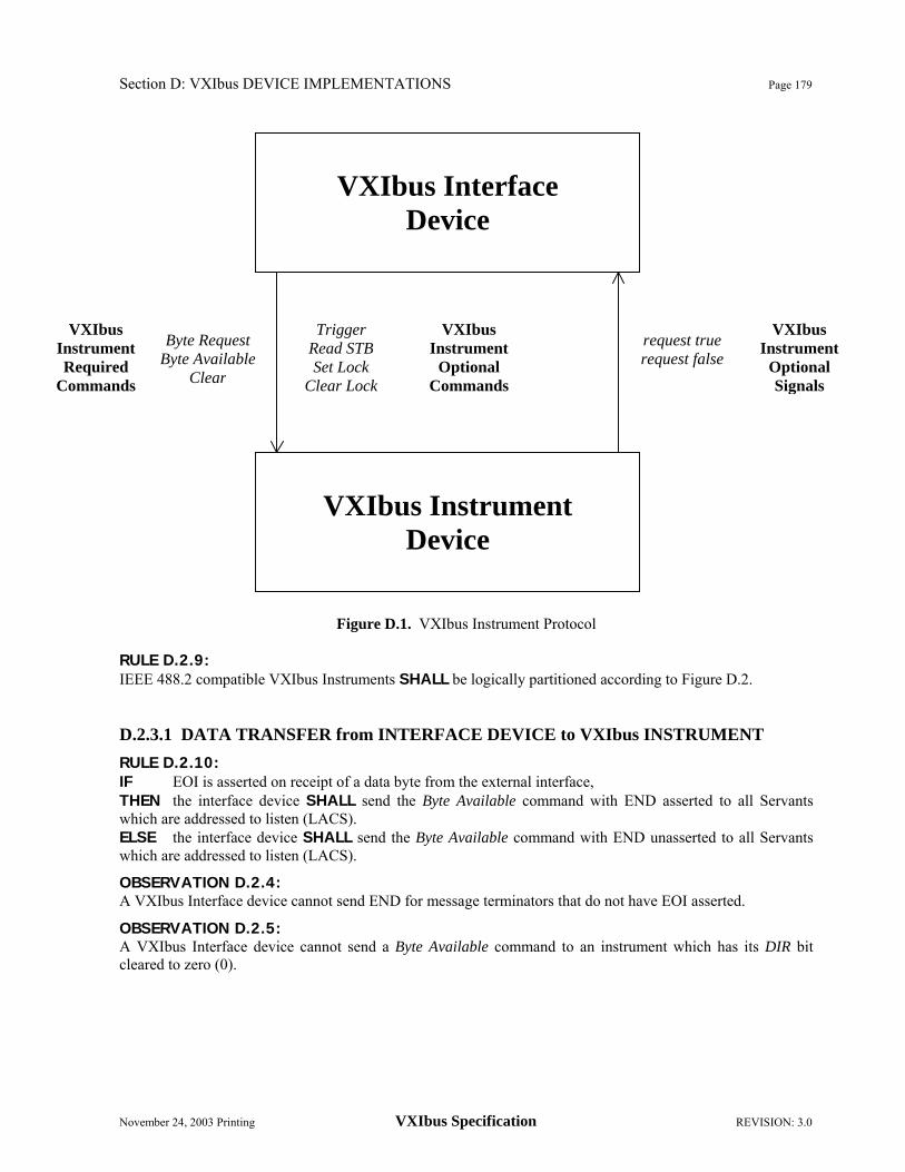
Section D: VXIbus DEVICE IMPLEMENTATIONS Page 179
November 24, 2003 Printing VXIbus Specification REVISION: 3.0
Figure D.1. VXIbus Instrument Protocol
RULE D.2.9: IEEE 488.2 compatible VXIbus Instruments SHALL be logically partitioned according to Figure D.2. D.2.3.1 DATA TRANSFER from INTERFACE DEVICE to VXIbus INSTRUMENT
RULE D.2.10: IF EOI is asserted on receipt of a data byte from the external interface, THEN the interface device SHALL send the Byte Available command with END asserted to all Servants which are addressed to listen (LACS). ELSE the interface device SHALL send the Byte Available command with END unasserted to all Servants which are addressed to listen (LACS).
OBSERVATION D.2.4: A VXIbus Interface device cannot send END for message terminators that do not have EOI asserted.
OBSERVATION D.2.5: A VXIbus Interface device cannot send a Byte Available command to an instrument which has its DIR bit cleared to zero (0).
VXIbus Interface
Device
VXIbus Instrument
Device
Trigger Read STB Set Lock
Clear Lock
VXIbus Instrument
Optional Commands
Byte Request Byte Available
Clear
request true request false
VXIbus Instrument Required
Commands
VXIbus Instrument
Optional Signals

Page 180 Section D: VXIbus DEVICE IMPLEMENTATIONS
REVISION: 3.0 VXIbus Specification November 24, 2003 Printing
488-VXIbus Interface Device get
IEEE 448.2 Compatible VXIbus Instrument
Figure D.2. Message Exchange Control Interface Functional Blocks
Response Message Elements
ib-empty ib-full
ExecutableMessageElements
Input Buffer
CommandError
GET MAV
bav brq dcas
IEEE 488.1Remote messages
IEEE 488.1 bus
Message Exchange Control
Parser
Response Formatter
Device Functions
Execution Control
I/O Control
TriggerControl
STB, reqt, reqf, ist
DABENDGET
DAB, END
Execution Error
Output Queue
ParsedMessageElement
DABENDGET
clear
reset
reset
eom,
pon
Query Error
Response Data
reset
clear
oq-full oq-empty
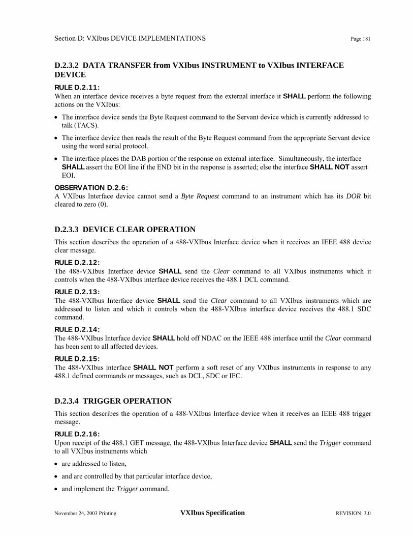
Section D: VXIbus DEVICE IMPLEMENTATIONS Page 181
November 24, 2003 Printing VXIbus Specification REVISION: 3.0
D.2.3.2 DATA TRANSFER from VXIbus INSTRUMENT to VXIbus INTERFACE DEVICE
RULE D.2.11: When an interface device receives a byte request from the external interface it SHALL perform the following actions on the VXIbus:
• The interface device sends the Byte Request command to the Servant device which is currently addressed to talk (TACS).
• The interface device then reads the result of the Byte Request command from the appropriate Servant device using the word serial protocol.
• The interface places the DAB portion of the response on external interface. Simultaneously, the interface SHALL assert the EOI line if the END bit in the response is asserted; else the interface SHALL NOT assert EOI.
OBSERVATION D.2.6: A VXIbus Interface device cannot send a Byte Request command to an instrument which has its DOR bit cleared to zero (0). D.2.3.3 DEVICE CLEAR OPERATION
This section describes the operation of a 488-VXIbus Interface device when it receives an IEEE 488 device clear message.
RULE D.2.12: The 488-VXIbus Interface device SHALL send the Clear command to all VXIbus instruments which it controls when the 488-VXIbus interface device receives the 488.1 DCL command.
RULE D.2.13: The 488-VXIbus Interface device SHALL send the Clear command to all VXIbus instruments which are addressed to listen and which it controls when the 488-VXIbus interface device receives the 488.1 SDC command.
RULE D.2.14: The 488-VXIbus Interface device SHALL hold off NDAC on the IEEE 488 interface until the Clear command has been sent to all affected devices.
RULE D.2.15: The 488-VXIbus interface SHALL NOT perform a soft reset of any VXIbus instruments in response to any 488.1 defined commands or messages, such as DCL, SDC or IFC. D.2.3.4 TRIGGER OPERATION
This section describes the operation of a 488-VXIbus Interface device when it receives an IEEE 488 trigger message.
RULE D.2.16: Upon receipt of the 488.1 GET message, the 488-VXIbus Interface device SHALL send the Trigger command to all VXIbus instruments which
• are addressed to listen,
• and are controlled by that particular interface device,
• and implement the Trigger command.

Page 182 Section D: VXIbus DEVICE IMPLEMENTATIONS
REVISION: 3.0 VXIbus Specification November 24, 2003 Printing
• and are not configured for triggering via an alternate trigger implementation. OBSERVATION D.2.7: The above rule allows an interface which knows that some Servants provide alternate trigger implementations to be triggered via that implementation.
RULE D.2.17: The 488-VXIbus Interface device SHALL hold off NDAC on the IEEE 488 interface until the Trigger command has been sent to all affected devices.
OBSERVATION D.2.8: There will be a time delay between the receipt of the Trigger command by the various VXIbus instruments in the VXIbus system.
OBSERVATION D.2.9: The possible inclusion of P1 only VXIbus devices in the system mandates a Trigger command rather than use of a trigger line.
RULE D.2.18: A VXIbus Interface device SHALL NOT send a Trigger command to an instrument which has its DIR bit cleared to zero (0). D.2.3.5 IEEE 488 REMOTE LOCAL
This section discusses the implementation of the IEEE-488 RL1 functions within the context of a VXIbus system. Local is defined as operations which are initiated from any non-VXIbus device interface. D.2.3.5.1 Locking Devices
The 488-VXIbus Interface will issue the Set Lock and Clear Lock commands according the remote/local state of the associated device as maintained by the state table according to the rules below.
RULE D.2.19: IF A 488-VXIbus Interface Device implements RL1, THEN it SHALL issue the Set Lock command to a device which implements the Set Lock command when the interface detects that device should have entered the RWLS state of the IEEE-488.1.
RULE D.2.20: IF A 488-VXIbus Interface Device implements RL1, THEN it SHALL issue the Clear Lock command to a device which implements the Clear Lock command when the interface detects that device should have exited the RWLS state of the IEEE-488.1. D.2.3.6 SRQ OPERATION
This section describes the 488-VXIbus Interface device requirements for support of the IEEE 488.2 SRQ capability. 488.2 simplifies the implementation of service request by requiring two synchronization messages which control the assertion of the 488.1 rsv message. Two messages are sourced by the device: the reqt is used to assert a 488.1 rsv (requires service message) and the reqf is used to asynchronously remove rsv. In a VXIbus system these messages are sent using the request true and request false events. The 488.2 synchronization protocols allow the interface device to:
• Assert SRQ if a previously "enabled" condition occurs.

Section D: VXIbus DEVICE IMPLEMENTATIONS Page 183
November 24, 2003 Printing VXIbus Specification REVISION: 3.0
• Keep SRQ asserted until the controller has recognized the service request and serial polled the device or the instrument has removed the request (by sending a request false event).
• Release SRQ when serial polled so that the controller can detect a SRQ from another instrument.
• Assert SRQ again if another condition occurs whether or not the controller has cleared the first condition.
For further clarification of SRQ and serial poll operation of the 488-VXIbus Interface device, see IEEE 488.2, Section 11.3.3, "Service Request Generation".
RULE D.2.21: A 488-VXIbus Interface device, upon receipt of a request true event from a VXIbus instrument, SHALL set the 488.1 rsv message true.
RULE D.2.22: A 488-VXIbus Interface device, upon receipt of a request false event from a VXIbus instrument, SHALL set the 488.1 rsv message false only if no request true has been received from any other VXIbus Instrument.
OBSERVATION D.2.10: The VXIbus interface device has to keep track of requests for each of its Servants in order to properly control the SRQ line on the IEEE 488.1 interface.
RULE D.2.23: A 488-VXIbus Interface device SHALL implement the IEEE 488.2 SRQ protocols.
OBSERVATION D.2.11: Request true and request false events may be sent via either interrupts or signals. The 488-VXIbus Interface device is required to accept these events regardless of method of transmission. D.2.3.7 SPOLL Operation
This section discusses the implementation of the IEEE 488 Serial Poll function within the context of a VXIbus system. The IEEE 488 specific functions, such as whether the device is in SPAS, are managed by the IEEE 488 VXIbus Interface device. When the IEEE 488-VXIbus interface device is ready to source the serial poll response to the 488 interface, it sends a Read STB command to the device for which the serial poll was requested. It then reads (using the word serial protocol) the status byte of the polled instrument and makes this byte available to the interface as the serial poll response.
RULE D.2.24: IF a VXIbus instrument supports the Read STB command, THEN the IEEE 488-VXIbus Interface device SHALL respond to a serial poll of that instrument with the status byte obtained by the Read STB command.
RULE D.2.25: IF a VXIbus instrument doesn't support the Read STB command THEN the IEEE 488-VXIbus Interface device SHALL respond to a serial poll of that instrument with bit 6 of the serial poll response byte properly indicating the rsv state of the instrument. Bit 6 will be set (to one (1)) if the instrument is requesting service, otherwise it is cleared (to zero (0)). RULE D.2.26: A IEEE 488-VXIbus Interface device SHALL implement SPOLL in the manner specified by IEEE 488.2.

Page 184 Section D: VXIbus DEVICE IMPLEMENTATIONS
REVISION: 3.0 VXIbus Specification November 24, 2003 Printing

Section E: Command and Event Formats Page 185
November 24, 2003 Printing VXIbus Specification REVISION: 3.0
E. COMMAND and EVENT FORMATS
This section summarizes the required and optional commands and events which support the instrument protocols. E.1 WORD SERIAL COMMANDS
The following commands are the standard set of VXIbus device commands which are sent with the word serial protocol.
RULE E.1.1 Message Based Devices SHALL implement the appropriate subsets of the following command set as specified in Table E.1 and E.2. Primary Classification All MBD I I4 CDMR MASTER Slot 0 Comments
Abort Normal Operation R R R R R R Begin Normal Operation R R R R R R Byte Available R R Requires DIR bit Byte Request R R Requires DOR bit Clear R R R R R R
Clear Lock Required with RL 1 Requires Locked* bit
End Normal Operation R R R R R R Grant Device R Identify Commander R R Read MODID R Read Protocol R R R R R R Read Protocol Error R R R R R R Read STB R Read Servant Area R Release Device R
Set Lock Required with RL 1 Requires Locked* bit
Set Lower MODID R Set Upper MODID R
Trigger Optional for all devices Requires DIR bit
R – Required for this type of device.
TABLE E.1. General Command Requirements

Page 186 Section E: Command and Event Formats
REVISION: 3.0 VXIbus Specification November 24, 2003 Printing
Programmable
Handler Programmable
Interrupter Response
Generation Event
Generation Comments
Assign Handler Line R Assign Interrupter Line R Asynchronous Mode Control R R Control Event R Control Response R Read Handler Line R Read Handlers R Read Interrupter Line R Read Interrupters R
R – Required for this type of device
TABLE E.2. Asynchronous Command Requirements
The following is a list of commands:
Abort Normal Operation: The Abort Normal Operation command is used to cause a device to cease normal operation. Upon receipt of this command the device returns to its default configuration, aborting all operations. The aborted state is defined as follows: All VMEbus Master activity is halted. Pending interrupts are unasserted. No new bus requests or interrupts may be asserted. The device is in a generally inactive state and is ready to accept commands.
The syntax of the Abort Normal Operation command is defined in the following table.
Bit #
15 14 13 12 11 10 9 8 7 6 5 4 3 2 1 0 1 1 0 0 1 0 0 0 1 1 1 1 1 1 1 1
When the abort operation has completed (the device is in the aborted state), response data is placed in the Data Low register in the following format:
Bit #
15 14 13 12 11 10 9 8 7 6 5 4 3 2 1 0 1 1 1 1 1 1 1 1 1 1 1 1 1 1 1 0

Section E: Command and Event Formats Page 187
November 24, 2003 Printing VXIbus Specification REVISION: 3.0
Assign Handler Line: The Assign Handler Line command is used to assign a VMEbus IRQ line to a particular Interrupt Handler in the Servant device. The syntax of this command is defined in the following table.
Bit # 15 14 13 12 11 10 9 8 7 6 5 4 3 2 1 0 1 0 1 0 1 0 0 1 X Hand _ID X Line
• X: Don't care. The value written to this bit has no effect.
• Hand_ID: This is a unique identifier of the particular Interrupt Handler being assigned. It has a range of 1 to 7. Within a device, multiple handlers are identified in consecutive order, starting at 1.
• Line: This is the VMEbus IRQ line number. A value of zero (016) indicates that the handler is to be disconnected.
When the assignment operation has completed, response data is placed in the Data Low register in the following format:
Bit # 15 14 13 12 11 10 9 8 7 6 5 4 3 2 1 0
Status 1 1 1 1 1 1 1 1 1 1 1 0 • Status: This field indicates the execution status of the command. It may have the following values:
- F16: The command successfully completed.
- 716: Command failed - The handler referenced in the Hand_ID field is unknown to this device.
OBSERVATION E.1.1 There is no implicit relationship between the Handler ID (Hand_ID) and the functionality of the associated handler.
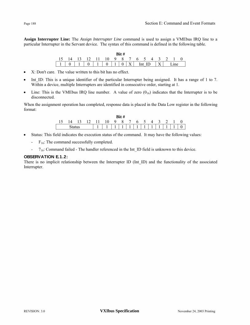
Page 188 Section E: Command and Event Formats
REVISION: 3.0 VXIbus Specification November 24, 2003 Printing
Assign Interrupter Line: The Assign Interrupter Line command is used to assign a VMEbus IRQ line to a particular Interrupter in the Servant device. The syntax of this command is defined in the following table.
Bit # 15 14 13 12 11 10 9 8 7 6 5 4 3 2 1 0 1 0 1 0 1 0 1 0 X Int_ID X Line
• X: Don't care. The value written to this bit has no effect.
• Int_ID: This is a unique identifier of the particular Interrupter being assigned. It has a range of 1 to 7. Within a device, multiple Interrupters are identified in consecutive order, starting at 1.
• Line: This is the VMEbus IRQ line number. A value of zero (016) indicates that the Interrupter is to be disconnected.
When the assignment operation has completed, response data is placed in the Data Low register in the following format:
Bit # 15 14 13 12 11 10 9 8 7 6 5 4 3 2 1 0
Status 1 1 1 1 1 1 1 1 1 1 1 0
• Status: This field indicates the execution status of the command. It may have the following values:
- F16: The command successfully completed.
- 716: Command failed - The handler referenced in the Int_ID field is unknown to this device.
OBSERVATION E.1.2: There is no implicit relationship between the Interrupter ID (Int_ID) and the functionality of the associated Interrupter.

Section E: Command and Event Formats Page 189
November 24, 2003 Printing VXIbus Specification REVISION: 3.0
Asynchronous Mode Control: The Asynchronous Mode Control command is used by a Commander to direct the path of events and responses. The syntax of this command is defined in the following table.
Bit #
15 14 13 12 11 10 9 8 7 6 5 4 3 2 1 0 1 0 1 0 1 0 0 0 X Resp. En* Event En* Resp. Mode Event Mode
The bits have the following meanings:
• X: Don't care. The value written to this bit has no effect.
• Resp. En*: A zero (0) enables generation of responses. A one (1) disables generation of responses.
• Event En*: A zero (0) enables generation of events. A one (1) disables generation of events.
• Resp. Mode: A one (1) indicates that responses should be sent as signals. A zero (0) indicates that responses should be sent as interrupts. This bit is meaningful only if the Resp En* bit is zero (0).
• Event Mode: A one (1) indicates that events should be sent as signals. A zero (0) indicates that events should be sent as interrupts. This bit is meaningful only if the Event En* bit is zero (0).
The result data is placed in the Data Low register with the following format. This result is a confirmation/denial of the command.
Bit # 15 14 13 12 11 10 9 8 7 6 5 4 3 2 1 0
Status 1 1 1 1 1 1 1 1 Resp. En* Event En* Resp. Mode Event Mode The bits have the following meanings: • Status: This field indicates the execution status of the command. It may have the following values:
- F16: The command successfully completed as expected.
- 716: Command failed - A requested option is not supported.
• Resp. En*: A zero (0) indicates that the generation of responses is enabled. A one (1) indicates that the generation of responses is disabled.
• Event En*: A zero (0) indicates that the generation of events is enabled. A one (1) indicates that the generation of events is disabled.
• Resp. Mode: A one (1) indicates that responses are being sent as signals. A zero (0) indicates that responses are being sent as interrupts. This bit is meaningful only if the Resp En* bit is zero (0).
• Event Mode: A one (1) indicates that events are being sent as signals. A zero (0) indicates that events are being sent as interrupts. This bit is meaningful only if the Event En* bit is zero (0).

Page 190 Section E: Command and Event Formats
REVISION: 3.0 VXIbus Specification November 24, 2003 Printing
Begin Normal Operation: The Begin Normal Operation command notifies the device that it can begin normal operation now. A Commander may not initiate any VMEbus operations after power-up until it receives the Begin Normal Operation command. It then sends the Begin Normal Operation command to all of its current Message Based Servants and begins normal execution of commands and/or application programs. The Top_Level field of the Begin Normal Operation command is provided to inform a device whether or not it is a top level Commander. The syntax of this command is defined in the following table.
Bit # 15 14 13 12 11 10 9 8 7 6 5 4 3 2 1 0 1 1 1 1 1 1 0 Top Level 1 1 1 1 1 1 1 1
• Top Level: A one (1) in this field indicates that the device is a top level Commander. A zero (0) indicates
that that it is a Servant to another device. When the begin operation has completed, response data is placed in the Data Low register in the following format:
Bit # 15 14 13 12 11 10 9 8 7 6 5 4 3 2 1 0
Status State Logical Address • Status: This field indicates the execution status of the command. It may have the following values:
- F16: The Begin Normal Operation command has been successfully executed. The value FE16 is reported in the Logical Address field.
- 716: The Commander device is not able to command a Servant. The Servant's Logical Address is reported in the Logical Address field.
- 616: The Commander device is not able to configure a Servant device. The Servants Logical Address is reported in the Logical Address field.
- 516: The Commander device timed out when waiting for response from a Servant device. The Servant's Logical Address is reported in the Logical Address field.
- 416: The device is not able to successfully initialize itself. The value FE16 is reported in the Logical Address field.
- 316: The device is not able to be a top level Commander. The value FE16 is reported in the Logical Address field.
- 216: The device must be a top level Commander. The value FE16 is reported in the Logical Address field.
- 116: An undefined error was caused. The value FE16 is reported in the Logical Address field.
• State: This field indicates the state of this device and its sub-tree. It may have the following values:
- 316: This device and all of its Servant tree are in the CONFIGURE sub-state.
- 716: This device is in the CONFIGURE sub-state, however at least one device in its Servant tree is in the NORMAL OPERATION sub-state.
- B16: This device is in the NORMAL OPERATION sub-state, however at least one device in its Servant tree is in the CONFIGURE sub-state.

Section E: Command and Event Formats Page 191
November 24, 2003 Printing VXIbus Specification REVISION: 3.0
- F16: This device and all of its Servant tree are in the NORMAL OPERATION sub-state.
• Logical Address: This field contains the Logical Address corresponding to the status field values. Byte Available: The Byte Available command is used by a Commander to send a byte of data to a Servant device. The END field identifies that this is the last byte of the message. The syntax of this command is defined in the following table.
Bit # 15 14 13 12 11 10 9 8 7 6 5 4 3 2 1 0 1 0 1 1 1 1 0 END Datum
Byte Request: The Byte Request command is used by a Commander to read a byte of data from a Servant device. The syntax of this command is defined in the following table.
Bit # 15 14 13 12 11 10 9 8 7 6 5 4 3 2 1 0 1 1 0 1 1 1 1 0 1 1 1 1 1 1 1 1
The result data is placed in the Data Low register with the following format. The END field is used to indicate the last byte of the message.
Bit # 15 14 13 12 11 10 9 8 7 6 5 4 3 2 1 0 1 1 1 1 1 1 1 END Datum
Clear: The Clear command is used by a Commander to cause a Servant device to clear the VXIbus interface and any pending operations. Any initiated operations in the receiving device are undisturbed. The syntax of this command is defined in the following table.
Bit # 15 14 13 12 11 10 9 8 7 6 5 4 3 2 1 0 1 1 1 1 1 1 1 1 1 1 1 1 1 1 1 1
Clear Lock: The Clear Lock command is used by a Commander to cause a Servant device to exit the locked state. When a device receives this command it will set its Locked* bit. The syntax of this command is defined in the following table.
Bit # 15 14 13 12 11 10 9 8 7 6 5 4 3 2 1 0 1 1 1 0 1 1 1 1 1 1 1 1 1 1 1 1

Page 192 Section E: Command and Event Formats
REVISION: 3.0 VXIbus Specification November 24, 2003 Printing
Control Event: The Control Event command is used by a Commander to selectively enable the generation of events by a Servant. A one (1) in the enable field enables the generation of the specific event. A zero (0) in the enable field disables the generation of the specific event. The syntax of this command is defined in the following table.
Bit # 15 14 13 12 11 10 9 8 7 6 5 4 3 2 1 0 1 0 1 0 1 1 1 1 Enable Event
• Event: These bits (6 ← 0) are the identifying bits (14 ← 8) of the event being enabled/disabled. See Section E.4, "Protocol Events", for further information.
The device returns the following data in the Data Low register:
Bit # 15 14 13 12 11 10 9 8 7 6 5 4 3 2 1 0
Status 1 1 1 1 1 1 1 1 1 1 1 0 • Status: This field indicates the execution status of the command. It may have the following values:
- F16: The command successfully completed.
- 716: Command failed - The event referenced is not generated by this device.

Section E: Command and Event Formats Page 193
November 24, 2003 Printing VXIbus Specification REVISION: 3.0
Control Response: The Control Response command is required for devices which implement response signals or response interrupts. It is used to enable response signals or response interrupts on certain response register bit transitions. The syntax of this command is defined in the following table.
Bit # 15 14 13 12 11 10 9 8 7 6 5 4 3 2 1 0 1 0 0 0 1 1 1 1 X B14* DOR* DIR* Err* RR* WR* FHS*
The bits have the following meanings:
• X: Don't care. The value written to this bit has no effect.
• B14*: A zero (0) enables a signal/interrupt on transitions of bit 14 of the Response register. A one (1) disables this capability. Since bit 14 of the Response register is reserved (always one), the value of this bit may be ignored by the Servant.
• DOR*: A zero (0) enables a signal/interrupt on a 0→1 transition of the DOR bit. A one (1) disables this capability.
• DIR*: A zero (0) enables a signal/interrupt on a 0→1 transition of the DIR bit. A one (1) disables this capability.
• Err*: A zero (0) enables a signal/interrupt on a 1→0 transition of the Err* bit. A one (1) disables this capability.
• RR*: A zero (0) enables a signal/interrupt on a 0→1 transition of the Read Ready bit. A one (1) disables this capability.
• WR*: A zero (0) enables a signal/interrupt on a 0→1 transition of the Write Ready bit. A one (1) disables this capability.
• FHS*: A zero (0) enables a signal/interrupt on a 1→0 transition of the FHS Active* bit. A one (1) disables this capability.
The result data is placed in the Data Low register with the following format. This result is a confirmation/denial of the command.
Bit # 15 14 13 12 11 10 9 8 7 6 5 4 3 2 1 0
Status 1 1 1 1 1 B14* DOR* DIR* Err* RR* WR* FHS* The bits have the following meanings:
• Status: This field indicates the execution status of the command. It may have the following values:
- F16: The command successfully completed as expected.
- 716: Command failed - an unsupported bit transition was requested.
• B14*: A zero (0) indicates that interrupt/signal generation on transitions of bit 14 of the Response register is enabled. A one (1) indicates that this capability is disabled. Since bit 14 of the Response register is reserved and should never change, this bit should always be set to one (1).
• DOR*: A zero (0) indicates that interrupt/signal generation on 0→1 transitions of the DOR bit is enabled. A one (1) indicates that this capability is disabled.

Page 194 Section E: Command and Event Formats
REVISION: 3.0 VXIbus Specification November 24, 2003 Printing
• DIR*: A zero (0) indicates that interrupt/signal generation on 0→1 transitions of the DIR bit is enabled. A one (1) indicates that this capability is disabled.
• Err*: A zero (0) indicates that interrupt/signal generation on 1→0 transitions of the Err* bit is enabled. A one (1) indicates that this capability is disabled.
• RR*: A zero (0) indicates that interrupt/signal generation on 0→1 transitions of the Read Ready bit is enabled. A one (1) indicates that this capability is disabled.
• WR*: A zero (0) indicates that interrupt/signal generation on 0→1 transitions of the Write Ready bit is enabled. A one (1) indicates that this capability is disabled.
• FHS*: A zero (0) indicates that interrupt/signal generation on 1→0 transitions of the FHS Active* bit is enabled. A one (1) indicates that this capability is disabled.
OBSERVATION E.1.3: A Servant may not implement response signals or response interrupts for some of the defined bits. Such a Servant will always return a one (1) in the corresponding bit position(s) in its response to the Control Response command.

Section E: Command and Event Formats Page 195
November 24, 2003 Printing VXIbus Specification REVISION: 3.0
End Normal Operation: The End Normal Operation command is used to cause a Commander to cease normal operation in an orderly manner. Upon receipt of this command the Commander issues the End Normal Operation command to all of its Message Based Servants. The Commander is responsible for halting all its Servants. The "ended" state is defined as follows: All VMEbus Master activity is halted. Pending interrupts are unasserted. No new bus requests or interrupts may be asserted. The device is in a generally inactive state and is ready to accept commands.
The syntax of the End Normal Operation command is defined in the following table.
Bit # 15 14 13 12 11 10 9 8 7 6 5 4 3 2 1 0 1 1 0 0 1 0 0 1 1 1 1 1 1 1 1 1
When the "ending" operation has completed, response data is placed in the Data Low register in the following format:
Bit # 15 14 13 12 11 10 9 8 7 6 5 4 3 2 1 0
Status State Logical Address
• Status: This field indicates the execution status of the command. It may have the following values:
- F16: The End Normal Operation command has been successfully executed. The value FE16 is reported in the Logical Address field.
- 716: The device was already in the CONFIGURE sub-state. The value FE16 is reported in the Logical Address field.
- 616: The Commander device timed out when waiting for the response from a Servant device. The Servants Logical Address is reported in the Logical Address field.
- 516: The device is not able to end its operation in a consistent manner. The value FE16 is reported in the Logical Address field.
- 416: The Commander device is not able to deactivate a Servant. The Servants Logical Address is reported in the Logical Address field.
- 316: An undefined error was caused. The value FE16 is reported in the Logical Address field.
• State: This field indicates the state of this device and its sub-tree. It may have the following values:
- F16: This device and all of its Servant tree are in the CONFIGURE sub-state.
- B16: This device is in the CONFIGURE sub-state, however at least one device in its Servant tree is in the NORMAL OPERATION sub-state.
- 916: This device is in the CONFIGURE sub-state, however the sub-states of the devices in its Servant tree are unknown.
- 716: This device is in the NORMAL OPERATION sub-state, however at least one device in its Servant tree is in the CONFIGURE sub-state.
- 316: This device and all of its Servant tree are in the NORMAL OPERATION sub-state.
• Logical Address: This field contains the Logical Address corresponding to the status field values.
OBSERVATION E.1.4: The End Normal Operation command, unlike the Abort Normal Operation command, allows for the completion of some pending operations before "ending".

Page 196 Section E: Command and Event Formats
REVISION: 3.0 VXIbus Specification November 24, 2003 Printing
Grant Device: The Grant Device command is used by the Resource Manager to inform a Commander of the Logical Address of its Servants. The syntax of this command is defined in the following table.
Bit # 15 14 13 12 11 10 9 8 7 6 5 4 3 2 1 0 1 0 1 1 1 1 1 1 Servant’s Logical Address
Identify Commander: The Identify Commander command is used by a Commander to tell a Servant the Commander's Logical Address. This command allows the Servant to reply with signals rather than interrupts. The syntax of this command is defined in the following table.
Bit # 15 14 13 12 11 10 9 8 7 6 5 4 3 2 1 0 1 0 1 1 1 1 1 0 Commander’s Logical Address
Read Handler Line: The Read Handler Line command is used to determine to which VMEbus IRQ line a particular Interrupt Handler in the Servant device is connected. The syntax of this command is defined in the following table.
Bit # 15 14 13 12 11 10 9 8 7 6 5 4 3 2 1 0 1 0 0 0 1 1 0 0 X Hand_ID
• X: Don't care. The value written to this field has no effect.
• Hand_ID: This is a unique identifier of the particular Interrupt Handler being queried. It has a range of 1 to 7. Within a device, multiple Interrupters are identified in consecutive order, starting at 1.
The VMEbus IRQ line number is placed in the Data Low register with the following format.
Bit # 15 14 13 12 11 10 9 8 7 6 5 4 3 2 1 0
Status 1 1 1 1 1 1 1 1 1 Line • Status: This field indicates the execution status of the command. It may have the following values:
- F16: The command successfully completed.
- 716: Command failed - The handler referenced in the Hand_ID field is unknown to this device.
• Line: This is the VMEbus IRQ line number currently assigned. A value of zero (016) indicates that the handler is disconnected.

Section E: Command and Event Formats Page 197
November 24, 2003 Printing VXIbus Specification REVISION: 3.0
Read Handlers: The Read Handlers command is used to determine the number of Interrupt Handlers within a Servant device. The syntax of this command is defined in the following table.
Bit #
15 14 13 12 11 10 9 8 7 6 5 4 3 2 1 0 1 1 0 0 0 1 1 1 1 1 1 1 1 1 1 1
The number of Interrupt Handlers is placed in the Data Low register with the following format.
Bit # 15 14 13 12 11 10 9 8 7 6 5 4 3 2 1 0 1 1 1 1 1 1 1 1 1 1 1 1 1 Hand_no
• Hand_no: This is the number of Interrupt Handlers within this device. Read Interrupter Line: The Read Interrupter Line command is used to determine to which VMEbus IRQ line a particular Interrupter in the Servant device is connected. The syntax of this command is defined in the following table.
Bit # 15 14 13 12 11 10 9 8 7 6 5 4 3 2 1 0 1 0 0 0 1 1 0 1 X Int_ID
• X: Don't care. The value written to this field has no effect.
• Int_ID: This is a unique identifier of the particular Interrupter being queried. It has a range of 1 to 7. Within a device, multiple Interrupters are identified in consecutive order, starting at 1.
The VMEbus IRQ line number is placed in the Data Low register with the following format.
Bit # 15 14 13 12 11 10 9 8 7 6 5 4 3 2 1 0
Status 1 1 1 1 1 1 1 1 1 Line
• Status: This field indicates the execution status of the command. It may have the following values:
- F16: The command successfully completed.
- 716: Command failed - The Interrupter referenced in the Int_ID field is unknown to this device.
• Line: This is the VMEbus IRQ line number currently assigned. A value of zero (016) indicates that the Interrupter is disconnected.

Page 198 Section E: Command and Event Formats
REVISION: 3.0 VXIbus Specification November 24, 2003 Printing
Read Interrupters: The Read Interrupters command is used to determine the number of Interrupters within a Servant device. The syntax of this command is defined in the following table
Bit # 15 14 13 12 11 10 9 8 7 6 5 4 3 2 1 0 1 1 0 0 1 0 1 0 1 1 1 1 1 1 1 1
The number of Interrupters is placed in the Data Low register with the following format.
Bit # 15 14 13 12 11 10 9 8 7 6 5 4 3 2 1 0 1 1 1 1 1 1 1 1 1 1 1 1 1 Int_no
• Int_no: This is the number of Interrupters within this device. Read MODID: The Read MODID command is used by a Commander to determine the state of the MODID lines controlled by a given Slot 0 device. The syntax of this command is defined in the following table.
Bit # 15 14 13 12 11 10 9 8 7 6 5 4 3 2 1 0 1 1 0 0 1 1 0 0 1 1 1 1 1 1 1 1
The resulting MODID status word is placed in the Data Low register with the following format.
Bit # 15 14 13 12 11 10 9 8 7 6 5 4 3 2 1 0 1 1 Output Enable MODID
• Output Enable: A one (1) in this position indicates that the Slot 0 device is driving the MODID lines.
• MODID: This field contains the state of the thirteen MODID lines.
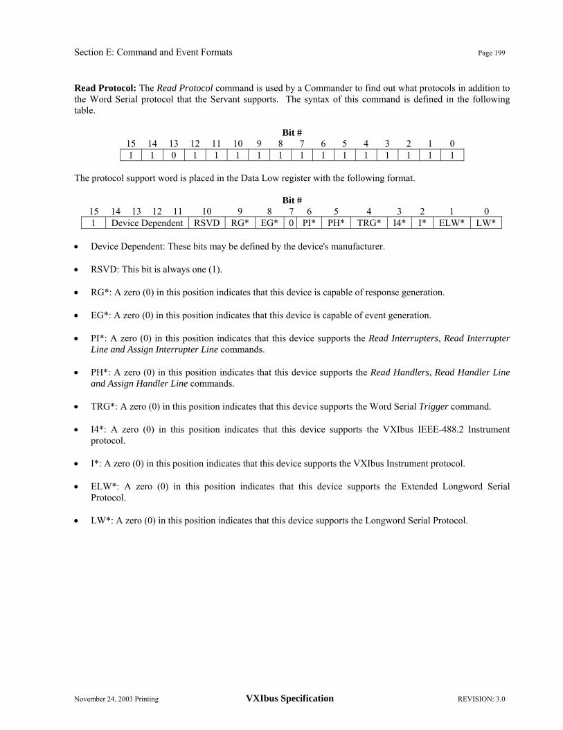
Section E: Command and Event Formats Page 199
November 24, 2003 Printing VXIbus Specification REVISION: 3.0
Read Protocol: The Read Protocol command is used by a Commander to find out what protocols in addition to the Word Serial protocol that the Servant supports. The syntax of this command is defined in the following table.
Bit # 15 14 13 12 11 10 9 8 7 6 5 4 3 2 1 0 1 1 0 1 1 1 1 1 1 1 1 1 1 1 1 1
The protocol support word is placed in the Data Low register with the following format.
Bit # 15 14 13 12 11 10 9 8 7 6 5 4 3 2 1 0 1 Device Dependent RSVD RG* EG* 0 PI* PH* TRG* I4* I* ELW* LW*
• Device Dependent: These bits may be defined by the device's manufacturer. • RSVD: This bit is always one (1). • RG*: A zero (0) in this position indicates that this device is capable of response generation. • EG*: A zero (0) in this position indicates that this device is capable of event generation. • PI*: A zero (0) in this position indicates that this device supports the Read Interrupters, Read Interrupter
Line and Assign Interrupter Line commands. • PH*: A zero (0) in this position indicates that this device supports the Read Handlers, Read Handler Line
and Assign Handler Line commands. • TRG*: A zero (0) in this position indicates that this device supports the Word Serial Trigger command. • I4*: A zero (0) in this position indicates that this device supports the VXIbus IEEE-488.2 Instrument
protocol. • I*: A zero (0) in this position indicates that this device supports the VXIbus Instrument protocol. • ELW*: A zero (0) in this position indicates that this device supports the Extended Longword Serial
Protocol. • LW*: A zero (0) in this position indicates that this device supports the Longword Serial Protocol.

Page 200 Section E: Command and Event Formats
REVISION: 3.0 VXIbus Specification November 24, 2003 Printing
Read Protocol Error: The Read Protocol Error command is used by a Commander to tell a Servant device to report its current error state as the 16-bit response to this command. The Err* bit is always reset before Write Ready is asserted in response to this command. After responding to this command, the servant will reset its current error state to "No Error". The syntax of this command is defined in the following table.
Bit # 15 14 13 12 11 10 9 8 7 6 5 4 3 2 1 0 1 1 0 0 1 1 0 1 1 1 1 1 1 1 1 1
The error codes are placed in the Data Low register with the following formats. No error:
Bit # 15 14 13 12 11 10 9 8 7 6 5 4 3 2 1 0 1 1 1 1 1 1 1 1 1 1 1 1 1 1 1 1
Multiple Queries: The device was requested to overwrite previous unread response data.
Bit # 15 14 13 12 11 10 9 8 7 6 5 4 3 2 1 0 1 1 1 1 1 1 1 1 1 1 1 1 1 1 0 1
Unsupported Command: This device has received a command that it does not implement.
Bit # 15 14 13 12 11 10 9 8 7 6 5 4 3 2 1 0 1 1 1 1 1 1 1 1 1 1 1 1 1 1 0 0
DIR Violation: This device has received a command that violates the DIR handshake.
Bit # 15 14 13 12 11 10 9 8 7 6 5 4 3 2 1 0 1 1 1 1 1 1 1 1 1 1 1 1 1 0 1 1
DOR Violation: This device has received a command that violates the DOR handshake.
Bit # 15 14 13 12 11 10 9 8 7 6 5 4 3 2 1 0 1 1 1 1 1 1 1 1 1 1 1 1 1 0 1 0
Read Ready Violation: This device has received a command that violates the Read Ready handshake.
Bit # 15 14 13 12 11 10 9 8 7 6 5 4 3 2 1 0 1 1 1 1 1 1 1 1 1 1 1 1 1 0 0 1
Write Ready Violation: This device has received a command that violates the Write Ready handshake.

Section E: Command and Event Formats Page 201
November 24, 2003 Printing VXIbus Specification REVISION: 3.0
Bit # 15 14 13 12 11 10 9 8 7 6 5 4 3 2 1 0 1 1 1 1 1 1 1 1 1 1 1 1 1 0 0 0
All other error codes are reserved for future use by VXIbus. Read STB: The Read STB command is used by a Commander to read the status word from a Servant device. The syntax of this command is defined in the following table.
Bit # 15 14 13 12 11 10 9 8 7 6 5 4 3 2 1 0 1 1 0 0 1 1 1 1 1 1 1 1 1 1 1 1
The status byte is placed in the Data Low register with the following format.
Bit # 15 14 13 12 11 10 9 8 7 6 5 4 3 2 1 0 1 1 1 1 1 1 1 1 Status Byte
Read Servant Area: The Read Servant Area command is used by the Resource Manager to read the Servant are A-size of Commanders in the system. The syntax of this command is defined in the following table.
Bit # 15 14 13 12 11 10 9 8 7 6 5 4 3 2 1 0 1 1 0 0 1 1 1 0 1 1 1 1 1 1 1 1
The Servant are A-size is placed in the Data Low register with the following format.
Bit # 15 14 13 12 11 10 9 8 7 6 5 4 3 2 1 0 1 1 1 1 1 1 1 1 Servant Area Size

Page 202 Section E: Command and Event Formats
REVISION: 3.0 VXIbus Specification November 24, 2003 Printing
Release Device: The Release Device command is used to cause a Commander to relinquish control of a specified Servant device. After releasing the Servant, the Commander will not attempt any further control of that Servant. The syntax of this command is defined in the following table.
Bit # 15 14 13 12 11 10 9 8 7 6 5 4 3 2 1 0 1 0 0 0 1 1 1 0 Servant Logical Address
The command termination status is placed in the Data Low register with the following format.
Bit # 15 14 13 12 11 10 9 8 7 6 5 4 3 2 1 0
Status 1 1 1 1 1 1 1 1 1 1 1 0
• Status: This field indicates the execution status of the command. It may have the following values:
- F16: The command successfully completed.
- 716: Command failed - The requested device is not in the Servant list.
Set Lock: The Set Lock command is used by a Commander to cause a Servant device to enter the locked state. When a device receives this command it will clear its Locked* bit. The syntax of this command is defined in the following table.
Bit # 15 14 13 12 11 10 9 8 7 6 5 4 3 2 1 0 1 1 1 0 1 1 1 0 1 1 1 1 1 1 1 1
Set Lower MODID: The Set Lower MODID command is used by a Commander to change the state of the MODID lines controlled by a given Slot 0 device. This command only effects the state of MODID0 through MODID6 (the lower 7 lines). The enable field, when set to one (1), causes the Slot 0 device to enable its MODID drivers (the function of this field is analogous to the output enable bit in the MODID register of a register based Slot 0 device). The syntax of this command is defined in the following table.
Bit # 15 14 13 12 11 10 9 8 7 6 5 4 3 2 1 0 1 0 1 0 1 1 1 0 Enable MODID6 – MODID0
Upon the completion of the MODID operation, the device places the following response in the Data Low register:
Bit # 15 14 13 12 11 10 9 8 7 6 5 4 3 2 1 0
Status 1 1 1 1 1 1 1 1 1 1 1 0
• Status: This field indicates the execution status of the command. It may have the following values:
- F16: The command successfully completed.
- 716: Command failed - The device is not installed in Slot 0.

Section E: Command and Event Formats Page 203
November 24, 2003 Printing VXIbus Specification REVISION: 3.0
Set Upper MODID: The Set Upper MODID command is used by a Commander to change the state of the MODID lines controlled by a given Slot 0 device. This command only effects the state of MODID7 through MODID12 (the upper 6 lines). The enable field, when set to one (1), causes the Slot 0 device to enable its MODID drivers (the function of this field is analogous to the output enable bit in the MODID register of a register based Slot 0 device). The syntax of this command is defined in the following table.
Bit # 15 14 13 12 11 10 9 8 7 6 5 4 3 2 1 0 1 0 1 0 1 1 0 1 Enable X MODID2 – MODID7
Upon the completion of the MODID operation, the device places the following response in the Data Low register:
Bit # 15 14 13 12 11 10 9 8 7 6 5 4 3 2 1 0
Status 1 1 1 1 1 1 1 1 1 1 1 0
• Status: This field indicates the execution status of the command. It may have the following values:
- F16: The command successfully completed.
- 716: Command failed - The device is not installed in Slot 0. Trigger: The Trigger command is used by a Commander to cause a Servant device to trigger any previously armed operation. The syntax of this command is defined in the following table.
Bit # 15 14 13 12 11 10 9 8 7 6 5 4 3 2 1 0 1 1 1 0 1 1 0 1 1 1 1 1 1 1 1 1
User Defined: The blocks of commands with the following bit patterns are reserved for device specific actions.
Bit # 15 14 13 12 11 10 9 8 7 6 5 4 3 2 1 0 0 User Defined Command
OBSERVATION E.1.5: Commands should indicate the presence of an error with a response which has bit 15 cleared to zero (0). All other commands are reserved for future use by VXIbus.

Page 204 Section E: Command and Event Formats
REVISION: 3.0 VXIbus Specification November 24, 2003 Printing
E.2 LONGWORD SERIAL COMMANDS
The following commands are the standard set of VXIbus device commands which are sent with the longword serial protocol.
User Defined: The blocks of commands with the following bit patterns are reserved for device specific actions.
Bit # 31 30 29 ← 0 1 0 User Defined Command
Bit #
31 30 ← 0 0 User Defined Command
All other commands are reserved for future use by VXIbus.

Section E: Command and Event Formats Page 205
November 24, 2003 Printing VXIbus Specification REVISION: 3.0
E.3 EXTENDED LONGWORD SERIAL COMMANDS
The following commands are the standard set of VXIbus device commands which are sent with the Extended Longword Serial protocol.
User Defined: The blocks of commands with the following bit patterns are reserved for device specific actions.
Bit # 47 46 45 ← 0 1 0 User Defined Command
Bit #
47 46 ← 0 0 User Defined Command
All other commands are reserved for future use by VXIbus.

Page 206 Section E: Command and Event Formats
REVISION: 3.0 VXIbus Specification November 24, 2003 Printing
E.4 PROTOCOL EVENTS
If a Message Based VXIbus Servant interrupts or signals its Commander, it may pass a response or an event in its Status/ID word. If the Status/ID word has bit 15 set to "1" then it is defined as an event. If bit 15 is "0" then it is defined as a response. The lower 8 bits are the Logical Address of the device. This section only covers events. For information on signals see the discussions of interrupts and signals in Section C.2.4, "Message Based Devices". No Cause Given: This event is sent by a device which has only one reason to signal its Commander. Usually this event will carry the meaning of operation complete. The syntax of this event is defined in the following table.
Bit # 15 14 13 12 11 10 9 8 7 6 5 4 3 2 1 0 1 1 1 1 1 1 1 1 Sender’s Logical Address
Request True: This event is sent by a device when the device requires service from its Commander. The syntax of this event is defined in the following table.
Bit # 15 14 13 12 11 10 9 8 7 6 5 4 3 2 1 0 1 1 1 1 1 1 0 1 Sender’s Logical Address
Request False: This event is sent by a device when the device no longer requires service from its Commander. The syntax of this event is defined in the following table.
Bit # 15 14 13 12 11 10 9 8 7 6 5 4 3 2 1 0 1 1 1 1 1 1 0 0 Sender’s Logical Address
User Defined: This block of events are reserved for use as user defined. The syntax of this event is defined in the following table.
Bit # 15 14 13 12 11 10 9 8 7 6 5 4 3 2 1 0 1 0 User Defined Sender’s Logical Address
All other events are reserved for future use by VXIbus.

Section F: DYNAMIC CONFIGURATION Page 207
November 24, 2003 Printing VXIbus Specification REVISION: 3.0
F. DYNAMIC CONFIGURATION
Dynamic Configuration is an optional, alternative method of assigning Logical Address to VXIbus devices, based upon slot positions. It allows for each slot to contain one or more devices. Provision is made for the different devices occupying a slot to share address decoding hardware. In addition, Dynamic Configuration requires hardware support in the devices being configured, as well as software support in the Resource Manager. The following sections present an overview of dynamic configuration, including definition of terms, hardware and software requirements and a description of the system configuration algorithm. F.1 DEFINITIONS
In the following pages, the abbreviation DC means "Dynamic Configuration" and the abbreviation SC means "Static Configuration."
• A DC device is a device whose Logical Address can be programmed via the VMEbus by a DC Resource Manager.
• An SC device is any device whose Logical Address is fixed manually and cannot be changed, except through manually configuring the device.
• A DC Resource Manager is a Resource Manager which supports Dynamic Configuration.
• A SC Resource Manager is any Resource Manager which does not support Dynamic Configuration, i.e., a Resource Manager as defined in Section C.4.1, "Resource Manager".
• A DC system is a VXIbus system with a DC Resource Manager.
• A SC system is a VXIbus system with a SC Resource Manager. F.2 DC DEVICE REQUIREMENTS
DC devices have the standard VXIbus configuration registers with some additional requirements. Each DC device has a Logical Address Register, used for setting the device's Logical Address. In addition, the device has certain information encoded in its Offset register at power-on. DC devices are also required to support the MODID line. F.2.1 Logical Address Register
RULE F.2.1: Each DC device SHALL have a writable Logical Address register located at address offset 0 (0016) of its configuration registers, conforming to the following format:
Bit # 15 ← 8 7 ← 0 Contents Undefined Logical Address
The fields of the Logical Address register are defined as follows:
• Undefined: The values written to these bits have no effect.
• Logical Address: The value written to this field is the device's new Logical Address.

Page 208 Section F: DYNAMIC CONFIGURATION
REVISION: 3.0 VXIbus Specification November 24, 2003 Printing
RULE F.2.2: A DC device SHALL move its Logical Address before DTACK* is released during the write cycle which transfers the new Logical Address.
RULE F.2.3: Any DC device which has moved to a new Logical Address SHALL NOT respond to any further accesses at its old Logical Address.
OBSERVATION F.2.1: Like all VXIbus devices, DC devices must have non-volatile Logical Address selectors.
PERMISSION F.2.1: A Static Configured VXIbus device MAY have a functional Logical Address register. F.2.2 DC Device Logical Address Assignment
A fundamental requirement of Dynamic Configuration is that at power-up time, all DC devices are set to Logical Address 255 (FF16). The Resource Manager will expect to find all DC devices at that Logical Address. Devices at all other addresses are assumed to be SC devices.
RULE F.2.4: Upon the assertion of SYSRESET*, a DC device SHALL assume the Logical Address indicated by its Logical Address Selector.
OBSERVATION F.2.2: Setting the Logical Address selector of a DC device to 255 (FF16) will cause a DC device to participate in the dynamic Logical Address assignment process. Setting the DC device Logical Address to any other Logical Address will fix the DC device at that Logical Address.
RULE F.2.5: SC-only devices SHALL NOT be set at Logical Address 255 (FF16) in DC systems. F.2.3 Offset Register
Multiple device modules may share address-decoding hardware. This can result in a significant hardware reduction. In such a case, the devices will share one or more Logical Address bits. A set of such devices is defined to be "address-blocked." These devices will be configured to a block of contiguous Logical Addresses. The Offset register is used to indicate the number of devices sharing the addressing hardware.
RULE F.2.6: After SYSRESET* is unasserted and prior to entering the SELF TEST state, a DC device SHALL load its Offset register in the following format:
Bit # 15 ← 8 7 ← 0 Contents Undefined Devices
The fields of the Offset register are defined as follows:
• Undefined: The contents of this field are undefined and not used.
• Devices: The value in this field is the number of devices sharing the common address-decoding hardware. Values of 0, 1 and 255 all indicate a single device.
The devices will have the least significant bits of their Logical Addresses hard wired to predetermined values and will share the decoding hardware for the most significant bits.

Section F: DYNAMIC CONFIGURATION Page 209
November 24, 2003 Printing VXIbus Specification REVISION: 3.0
RULE F.2.7: A set of address-blocked DC devices SHALL share address bits in accordance with the following table:
Devices Shared Bits Hard-coded bits 2 7 ← 1 0
3 - 4 7 ← 2 1 ← 0 5 - 8 7 ← 3 2 ← 0
9 – 16 7 ← 4 3 ← 0 17 - 32 7 ← 5 4 ← 0 33 - 64 7 ← 6 5 ← 0
65 – 128 7 6 ← 0 129 - 254 - 7 ← 0
RULE F.2.8: A set of address-blocked DC devices SHALL implement the lowest-valued block of contiguous Logical Addresses possible within its hard-coded bits.
OBSERVATION F.2.3: The above rule guarantees that a set of address-blocked DC devices occupy the lowest-valued addresses available with its block of available addresses.
OBSERVATION F.2.4: A write to the Logical Address register of an address-blocked module sets the values of all the related devices' Logical Addresses. F.2.4 MODID Support
A DC device, when at Logical Address 255 (FF16), uses the MODID line as a device select qualifier. The device responds to data transfers when MODID is asserted. After the device has been moved to another address, the device responds at that address independent of the state of the MODID line.
RULE F.2.9: A DC device SHALL use its MODID line as a device select qualifier for Logical Address 255 (FF16).
RULE F.2.10: A DC device SHALL NOT use MODID as a device select qualifier for any Logical Address other than 255 (FF16).
OBSERVATION F.2.5: The effect of writes to a DC device's Logical Address register is independent of the state of the MODID line. Once the device has been assigned an address other than 255, writes to its Logical Address register will change its logical address, whether or not the MODID line is asserted.
RULE F.2.11: DC modules which contain multiple DC entities which implement independent address decoding hardware SHALL respond to sequential accesses to Logical Address 255 (FF16), qualified with that module's MODID line, one entity at a time, until all entities have been moved to new Logical Addresses.
OBSERVATION F.2.6: The entities referred to in the preceding rule may be single devices or a set of devices sharing address-decoding hardware.

Page 210 Section F: DYNAMIC CONFIGURATION
REVISION: 3.0 VXIbus Specification November 24, 2003 Printing
RULE F.2.12: A multiple-board DC module must respond to exactly one MODID line, specified by the device designer. F.3 DC SYSTEM REQUIREMENTS
The DC system Resource Manager must include the software necessary to implement the three-part configuration algorithm defined in the following section. Additionally, some limitations are imposed on Resource Manager and Slot 0 devices. RULE F.3.1: A DC system SHALL include a DC Resource Manager.
RULE F.3.2: DC Resource Managers SHALL perform the system configuration responsibilities outlined in Section C.4.1, "Resource Manager", except for the Device Identification and Commander/Servant Hierarchy steps alternatively defined in the following paragraphs. OBSERVATION F.3.1: To meet the requirements of Section C.4.1, the DC Resource Manager must reside at Logical Address 0 (0016). Therefore, the Resource Manager must be a SC device and cannot be dynamically configured.
A DC Resource Manager uses the Slot 0 controlled MODID lines as board select qualifiers when assigning Logical Addresses. To access the Slot 0 devices, the Resource Manager must know the Logical Addresses of the system Slot 0 devices. RULE F.3.3: Slot 0 devices SHALL be SC devices; i.e., Slot 0 devices cannot be dynamically configured. OBSERVATION F.3.2: SC devices may be included in a DC system.
RULE F.3.4: Unless it is the Resource Manager, a VXIbus device SHALL NOT modify the logical address of any other VXIbus device by writing to its Logical Address register. F.3.1 System Configuration Algorithm
To configure a Dynamic Configuration system, the DC system Resource Manager must perform the following three major functions:
• SC Device Identification
• DC Device Logical Address Assignment
The previous two functions modify the "Device Identification" step of the initialization process outlined in Section C.4.1, "Resource Manager".
• Hierarchy Construction
This function modifies the "Assign Commander/Servant Hierarchies" step of the initialization process outlined in Section C.4.1, "Resource Manager".

Section F: DYNAMIC CONFIGURATION Page 211
November 24, 2003 Printing VXIbus Specification REVISION: 3.0
F.3.1.1 SC DEVICE IDENTIFICATION
In any Dynamic Configuration system, there will always be at least one and possibly several SC devices present: the DC Resource Manager and the system Slot-0 device(s). Also, users may wish to install other types of SC devices in DC systems. Since the Logical Addresses of these SC devices are fixed, the DC Resource Manager must first identify all SC devices as specified in Section C.4.1.1, "Device Identification". Having located the SC devices, the DC Resource Manager will not attempt to assign their Logical Addresses to any DC devices.
OBSERVATION F.3.3: If an SC device is found at Logical Address 255 (FF16), no DC devices may be configured. F.3.1.2 DC DEVICE LOGICAL ADDRESS ASSIGNMENT
After identifying the SC devices, the DC Resource Manager must assign Logical Addresses to all of the DC devices in the system. This requires that the DC Resource Manager:
• Find every DC device by asserting each MODID line and reading a configuration register at Logical Address 255 (FF16).
AND
• Write a new Logical Address to each DC device's Logical Address register.
OBSERVATION F.3.4: No single order of asserting MODID lines is mandated. The order in which a DC Resource Manager asserts the MODID lines is at its manufacturer's discretion. Consequently, the order in which Logical Addresses are assigned to DC devices may vary from system to system.
PERMISSION F.3.1: In assigning Logical Addresses, the DC Resource Manager may skip the access of slots which are known to contain SC devices.
A DC resource manager may implement any procedure which assigns Logical Addresses to every DC device in the system, such as the following:
For every Slot #1 - 12 in the system do the following steps (1 - 3):
1. Assert the selected slot's MODID line.
2. Repeat the following steps (a - c) until a bus error occurs.
a. Read the Offset register at Logical Address 255 (FF16).
b. If the Offset register indicates a single device, then determine the Logical Address to be assigned to that device.
Otherwise, a set of address blocked devices is being accessed. Determine the Logical Addresses to be assigned to these devices (the lowest address of the block is written in the next step).
c. Write the new Logical Address to the Logical Address register at Logical Address 255 (FF16).
OBSERVATION F.3.5: An address blocked group of devices will modify only the shared bits of their Logical Addresses. The hard coded bits will cause the devices to occupy the lowest available Logical Addresses within the block defined by the shared bits. As a consequence, the first device will have Logical Address B*2H, where B is the value assigned to the shared Logical Address bits and H is the number of hard-coded Logical Address bits. The last device will have Logical Address B*2H + D - 1, where D is the number
Page 212 Section F: DYNAMIC CONFIGURATION
REVISION: 3.0 VXIbus Specification November 24, 2003 Printing
of address blocked devices in the group. The Logical Addresses B*2H + D through (B +1)*2H -1 will be unused and available for assignment to other devices.
RECOMMENDATION F.3.1: A DC resource manager should verify that each DC device is at its new Logical Address by reading a configuration register at the new Logical Address.
3. De-assert the MODID line. F.3.1.3 HIERARCHY CONSTRUCTION
DC Resource Managers are not required to respect the system hierarchy configuration encoded in the Servant are A-size of the system devices, as defined in Section C.4.1.4, "Commander/Servant Hierarchies".
RULE F.3.5: IF the DC Resource Manager does not respect the hierarchy encoded in the Servant are A-size of the system devices, THEN the DC Resource Manager SHALL provide some means for building an initial hierarchy.

Appendix I: VXIbus REGISTER OVERVIEWS Page 213
November 24, 2003 Printing VXIbus Specification REVISION: 3.0
APPENDIX I. VXIbus REGISTER OVERVIEWS
This section is provided to improve the overview of the VXIbus configuration registers. The following figures contain register maps for the various device types and register contents overviews.
Signature explanation:
[ ]: Optional register or field
# : Register with location monitor
( ): Required for particular type of device.

Page 214 Appendix I: VXIbus REGISTER OVERVIEWS
REVISION: 3.0 VXIbus Specification November 24, 2003 Printing
Figure I.1. Register Map for Register Based Devices
3E3C3A38363432302E2C2A28262422201E1C1A18161412100E0C0A0806040200
DEVICE DEPENDENTREGISTERS
BASICCONFIGURATIONREGISTERS
(Slot 0 : MODID Register)[Offset Register]
Status / Control RegisterDevice TypeID Register
16 bit words
Enhanced Capabilities Register

Appendix I: VXIbus REGISTER OVERVIEWS Page 215
November 24, 2003 Printing VXIbus Specification REVISION: 3.0
Figure I.2 Register Map for Memory Devices
3E3C3A38363432302E2C2A28262422201E1C1A18161412100E0C0A0806040200
DEVICE DEPENDENTREGISTERS
BASICCONFIGURATIONREGISTERS
Attribute Register[Offset Register]
Status / Control RegisterDevice TypeID Register
16 bit words
Enhanced Capabilities Register

Page 216 Appendix I: VXIbus REGISTER OVERVIEWS
REVISION: 3.0 VXIbus Specification November 24, 2003 Printing
Figure I.3. Register Map for Message Based Devices
3E3C3A38363432302E2C2A28262422201E1C1A18161412100E0C0A0806040200
DEVICEDEPENDENTREGISTERS
BASICCONFIGURATIONREGISTERS
Protocol [ / Signal ] Register[Offset Register]
Status / Control RegisterDevice TypeID Register
16 bit words
Response [ / Data Extended ][ Data High ]
Data Low[ A24 Pointer High ][ A24 Pointer Low ][ A32 Pointer High ][ A32 Pointer Low ]
CONFIGURATIONREGISTERS
SHAREDMEMORYPROTOCOLREGISTERS
VXIbusRESERVEDREGISTERS
Enhanced Capabilities Register

Appendix I: VXIbus REGISTER OVERVIEWS Page 217
November 24, 2003 Printing VXIbus Specification REVISION: 3.0
Figure I.4. Register Map for Extended Devices
3E3C3A38363432302E2C2A28262422201E1C1A18161412100E0C0A0806040200
DEVICE DEPENDENTREGISTERS
BASICCONFIGURATIONREGISTERS
[Offset Register]Status / Control Register
Device TypeID Register
16 bit words
DEVICE DEPENDENTREGISTERS
Subclass RegisterEnhanced Capabilities Register

Page 218 Appendix I: VXIbus REGISTER OVERVIEWS
REVISION: 3.0 VXIbus Specification November 24, 2003 Printing
Figure I.5. Register Overview for Basic Configuration Registers
BAS
IC C
ON
FIG
UR
ATI
ON
RE
GIS
TER
S
DE
VIC
ED
EP
EN
DE
NT
RE
GIS
TER
S
BAS
ICC
ON
FIG
UR
ATIO
NR
EG
ISTE
RS
16 b
it w
ords
1E 1C 1A 18 16 14 12 10 0E 0C 0A 08 06 04 02 00
[ Offs
et R
egis
ter ]
Stat
us /
Con
trol R
egis
ter
Dev
ice
Type
ID R
egis
ter
1514
1312
1110
98
76
54
32
10
Rea
dW
rite06
A24/
32 O
ffset
A24/
32 O
ffset
1514
1312
1110
98
76
54
32
10
04W
rite
Rea
d
A24
A32
Ene
A24
A32 Act
MO
D-
ID*
Dev
ice
Dep
ende
ntD
evic
e D
epen
dent
D
evic
e D
epen
dent
Sys
fIn
hR
st
Rdy
Pas
sD
ev D
ep
1514
1312
1110
98
76
54
32
10
Writ
eR
ead02
RE
SER
VED
Requ
ired
Mem
ory
Mod
el C
ode
1514
1312
1110
98
76
54
32
10
Writ
eR
ead00
RE
SER
VED
[ Log
ical
Add
ress
]D
evice
Clas
sA
ddr
ess
Spa
ceM
anuf
actu
rer I
D
Enha
nced
Cap
abili
ties
Reg
iste
r15
1413
1211
109
87
65
43
21
0
Rea
dW
rite
1CR
ES
ERV
EDR
ES
ERV
EDAd
dres
sM
ode

Appendix I: VXIbus REGISTER OVERVIEWS Page 219
November 24, 2003 Printing VXIbus Specification REVISION: 3.0
Figure I.6. Register Overview for MODID Register in Register Based Slot 0 Devices
DEV
ICE
DEP
END
EN
TR
EGIS
TER
S
BA
SIC
CO
NFI
GU
RA
TIO
NR
EGIS
TER
S
16 b
it w
ords
1E 1C 1A 18 16 14 12 10 0E 0C 0A 08 06 04 02 00
[ Offs
et R
egis
ter ]
Sta
tus
/ Con
trol R
egis
ter
Dev
ice
Type
ID R
egis
ter
MO
DID
Reg
iste
r
1 51 4
1 31 2
1 11 0
98
76
54
32
10
Rea
d
Writ
e08
MO
DID
00-1
2
MO
DID
00-1
2
Res
erve
d
Res
erve
d
OE
OE
MO
DID
RE
GIS
TER
Enha
nced
Cap
abili
ties
Reg
iste
r

Page 220 Appendix I: VXIbus REGISTER OVERVIEWS
REVISION: 3.0 VXIbus Specification November 24, 2003 Printing
Figure I.7. Register Overview for Attribute Register in Memory Devices
DE
VIC
ED
EP
EN
DE
NT
RE
GIS
TER
S
BA
SIC
CO
NFI
GU
RA
TIO
NR
EG
ISTE
RS
16 b
it w
ords
1E 1C 1A 18 16 14 12 10 0E 0C 0A 08 06 04 02 00
[ Offs
et R
egis
ter ]
Sta
tus
/ Con
trol R
egis
ter
Dev
ice
Type
ID R
egis
ter
Attr
ibut
e R
egis
ter
Attr
ibut
e R
egis
ter
1 51 4
1 31 2
1 11 0
98
76
54
32
10
Writ
e
Rea
d08
RE
SE
RV
EDM
emor
yTy
peN
/SBT
*N
_P*
Acc
ess
Spee
dD
32*
RE
SER
VED
Dev
ice
Dep
ende
nt
Enh
ance
d C
apab
ilitie
s R
egis
ter

Appendix I: VXIbus REGISTER OVERVIEWS Page 221
November 24, 2003 Printing VXIbus Specification REVISION: 3.0
Figure I.8. Register Overview for Subclass Register in Extended Devices
1 51 4
1 31 2
1 11 0
98
76
54
32
10
Rea
d
Writ
e
1E
RE
SE
RV
ED
Res
erve
d S
ubcl
ass
Rea
d
1 0M
anuf
actu
rer
Sub
clas
sM
anuf
actu
rer I
D
DE
VIC
ED
EP
EN
DE
NT
RE
GIS
TER
S
BA
SIC
CO
NFI
GU
RA
TIO
NR
EG
ISTE
RS
16 b
it w
ords
1E 1C 1A 18 16 14 12 10 0E 0C 0A 08 06 04 02 00
[ Offs
et R
egis
ter ]
Sta
tus
/ Con
trol R
egis
ter
Dev
ice
Type
ID R
egis
ter
Sub
clas
s R
egis
ter
Enh
ance
d C
apab
ilitie
s R
egis
ter

Page 222 Appendix I: VXIbus REGISTER OVERVIEWS
REVISION: 3.0 VXIbus Specification November 24, 2003 Printing
Figure I.9. Register Overview for Communication Registers
BA
SIC
CO
NFI
GU
RA
TIO
NR
EG
ISTE
RS
16 b
it w
ords
1E 1C 1A 18 16 14 12 10 0E 0C 0A 08 06 04 02 00
[ Offs
et R
egis
ter ]
Sta
tus
/ Con
trol R
egis
ter
Dev
ice
Type
ID R
egis
ter
[ A32
Poi
nter
Low
]
[ A32
Poi
nter
Hig
h ]
[ A24
Poi
nter
Low
]
[ A24
Poi
nter
Hig
h ]
Dat
a Lo
w
[ Dat
a H
igh
]
Res
pons
e[ /
Dat
a E
xten
ded
]
Pro
toco
l [ /
Sig
nal ]
Reg
iste
r
CO
MM
UN
ICA
TIO
NR
EG
ISTE
RS
SH
AR
ED
ME
MO
RY
PR
OTO
CO
LR
EG
ISTE
RS
VX
I bus
RE
SE
RV
ED
RE
GIS
TER
S
1 51 4
1 31 2
1 11 0
98
76
54
32
10
0C
Writ
e
Rea
d
Dat
a H
igh
Dat
a H
igh
# #
1 51 4
1 31 2
1 11 0
98
76
54
32
10
Rea
d
Writ
e
0E
Dat
a Lo
w
Dat
a Lo
w
# #
1 51 4
1 31 2
1 11 0
98
76
54
32
10
Rea
d
Writ
e10
A24
Poi
nter
Hig
h
A24
Poi
nter
Hig
h
1 51 4
1 31 2
1 11 0
98
76
54
32
10
Rea
d
Writ
e12
A24
Poi
nter
Low
A24
Poi
nter
Low
1 51 4
1 31 2
1 11 0
98
76
54
32
10
Rea
d
Writ
e14
A32
Poi
nter
Hig
h
A32
Poi
nter
Hig
h
1 51 4
1 31 2
1 11 0
98
76
54
32
10
Rea
d
Writ
e16
A32
Poi
nter
Low
A32
Poi
nter
Low
1 51 4
1 31 2
1 11 0
98
76
54
32
10
Writ
e
Rea
d
0A
Dat
a E
xten
ded
0 R
svd
DO
RD
IREr
r*R
dR
dyW
rR
dyFH
SA
ct*
Lock *
Dev
ice
Dep
ende
nt
#
1 51 4
1 31 2
1 11 0
98
76
54
32
10
Eve
nt W
rite
Res
pons
e W
rite08
Eve
ntLo
gica
l Add
ress
Rea
d
#1 0
CM
DR
*
Rsv
d
Sig
. R
. M
as-
ter*
Int
DO
RD
IREr
r*
FHS *
SM
P *Rd
Rdy
Wr
Rdy
FHS
Act* RE
SE
RV
ED
Dev
ice
Dep
ende
nt
Logi
cal A
ddre
ss#
#: re
gist
er h
as lo
catio
n m
onito
r
Enh
ance
d C
apab
ilitie
s R
egis
ter

Appendix II: SUGGESTED BACKPLANE DESIGN Page 223
November 24, 2003 Printing VXIbus Specification REVISION: 3.0
APPENDIX II. SUGGESTED BACKPLANE DESIGN II.1 BACKPLANE STRUCTURE
A reasonable backplane layer assignment that minimizes noise and maximizes high frequency performance follows:
TOP (CONNECTOR SIDE) 1 GROUND PLANE 2 SIGNAL LAYER (TTL) 3 +5 VOLT PLANE 4 GROUND PLANE 5 -5.2 VOLT PLANE 6 -2 VOLT PLANE 7 SIGNAL LAYER (ECL) 8 GROUND PLANE
BOTTOM (SOLDER SIDE)
By making layers 1 and 8 ground planes, EMI is reduced because of the shielding of the internal traces. Layer 1 also provides the ground layer for attachment of the EMI gasketing to the instrument modules. The thickness between planes 3 and 4, planes 4 and 5 and planes 6 and 7 should be as small as possible (0.005 inches is reasonable). This provides high distributed capacitance between those layers and allows high di/dt in the voltage planes. One signal layer also exists between the ground layer and the + 5 layer. Since -2 Volts is the signal return for ECL signals, layer 7 should contain as many of the critical ECL signals as possible. II.2 BACKPLANE LAYOUT
While noise in any logic system can be due to electrostatic coupling, the primary means of coupling is usually due to electromagnetic coupling. The key to designing a low noise system, where electromagnetic coupling is the primary noise source, is the control of current loop areas. Shields or guard stripes do not work. In fact, the main reason for a ground plane is not that is a shield, but that if signal current is adjacent to a neighboring plane, the width of the loop is the spacing between the signal current and that plane. This creates the smallest possible loop area. A designer should always examine the route that any return current may take.

Page 224 Appendix II: SUGGESTED BACKPLANE DESIGN
REVISION: 3.0 VXIbus Specification November 24, 2003 Printing
Figure II.1. Typical Logic Circuits
In Figure II.1, if Circuit number 1 is driven, then there must be a return current. This return current forms a loop, called loop area 1. Circuit number 2 is assumed to be quiet. However there is also a loop area in this circuit which consists of the signal current path and the return current path. The noise induced in the signal line of Circuit number 2 is directly proportional to the loop areas 1 and 2. If these two loop areas are large enough, it is possible to generate a voltage in Circuit number 2 large enough to create a threshold crossing.
Please note that there is another "hidden" loop in Figure II.1. This is the power supply current path. When the receiving gate in Circuit number 1 changes state, a large amount of current is drawn from the supply voltage line. If a voltage plane is used, the loop area due to this current will be small. If a plane isn't used (or if the plane is discontinuous), then the loop area of the power supply return current can be quite large (it could encompass the entire board). If this area is not controlled, it can easily become the dominant noise source. In fact, when ground and voltage planes are not used, this power supply loop is almost always the dominant noise source. If power and ground planes are used, the need for external capacitors is reduced because of the high distributed capacitance.
IT IS HIGHLY RECOMMENDED THAT GROUND AND VOLTAGE PLANES ALWAYS BE USED (PARTICULARLY ON THE BACKPLANE) AND A LOW INDUCTANCE, LOW ESR 0.001 µF CAPACITOR BE PLACED AS CLOSE AS POSSIBLE TO THE POWER AND GROUND PINS OF GATES.
+ 5 Volts
Return Current
Loop Area 1
Signal Current0.001 µF Low
Inductance Capacitor
Circuit number 1
Circuit number 2
Loop Area 2

Appendix II: SUGGESTED BACKPLANE DESIGN Page 225
November 24, 2003 Printing VXIbus Specification REVISION: 3.0
Figure II.2 shows a pair of gates that exist on a PC board with a ground plane, but with a cut made in the ground plane.
Figure II.2. Loop Area with Cut in Ground Plane In Figure II.2 the signal is routed on a layer other than the ground plane. If the "ground plane cut" had not been made the return current would exist adjacent to the signal run, but on the ground plane. With the "cut" the return current is forced away from the signal current, creating a large loop area. The layout shown in Figure II.2 will typically create large amounts of noise. It will also typically receive large amounts of noise. FOR BEST RESULTS DON'T MAKE ANY CUTS IN A GROUND PLANE OR VOLTAGE PLANE FOR ANY REASON.
Signal Trace
GroundReturn Path
Backplane Cutout
Backplane

Page 226 Appendix II: SUGGESTED BACKPLANE DESIGN
REVISION: 3.0 VXIbus Specification November 24, 2003 Printing
Figure II.3. Backplane Cutouts for Connectors
In Figure II.3 two connectors are shown. In connector 2, the plane is not routed between pins. This can force large loop areas. In fact, this design is susceptible to simultaneous switching of signal lines, creating pattern sensitive noise. This noise can be high enough to cross a threshold for certain bit patterns.
IT IS HIGHLY RECOMMENDED THAT VOLTAGE AND GROUND PLANES BE CONNECTED BETWEEN THE PINS OF ALL BACKPLANE CONNECTORS.
Backplane
RIGHT WRONG
Connector 2 Connector 1
APPENDIX III: SUPPORT of EARLIER REVISIONS Page 227
November 24, 2003 VXIbus Specification REVISION: 3.0
APPENDIX III. Support of Earlier VXIbus Revisions
As the VXIbus specification has evolved, it has been necessary to tighten some of its requirements in order to minimize incompatibilities between devices. This appendix highlights the most important differences between this document and its earlier versions. In addition, it offers recommendations for maximizing compatibility with earlier implementations. III.1 REVISION 1.2 DEVICES
Some word serial commands that were optional in Revision 1.2 of the VXIbus specification are now required. Revision 1.2 also permitted some activities that are now prohibited. The following is a minimal set of exceptions to the present specification which, if implemented by the Commander or Resource Manager, should provide compatible support of a Revision 1.2 servant-only device. A bit in the response to the Read Protocol command identifies Revision 1.2 devices.
RECOMMENDATION III.1.1: A Resource Manager should implement the following operational changes when communicating with a Revision 1.2 Message Based device.
• Identify any Message Based device that responds to the Read Protocol command with bit 15 cleared to (0) as a Revision 1.2 device.
• Identify any Revision 1.2 devices that do not support the Err* bit. This is indicated by a 1 in bit 7 of the response to the Read Protocol command.
• If the device does not support the Err* bit, the device will report unsupported commands with the "unrecognized command" event which was defined for Revision 1.2 Message Based devices. This event will be returned as an event signal if the device is a VMEbus Master or as an event interrupt if the device is not a Master. The Resource Manager should provide an event handler for these "unrecognized command" events and utilize the unsupported command information as necessary.
• A Revision 1.2 device will not return a response to the Begin Normal Operation command. Therefore a Resource Manager or Commander should not expect one.
• Revision 1.2 did not prohibit interrupt generation by a device when not in the NORMAL OPERATION sub-state. The Resource Manager should not send the Read STB, Read Protocol Error, End Normal Operation or Abort Normal Operation commands (all optional in Revision 1.2) to a device prior to a Begin Normal Operation command to avoid unwanted interrupts prior to the NORMAL OPERATION sub-state.
• The End Normal Operation and Abort Normal Operation commands were optional commands for servant-only devices in Revision 1.2. Resource Managers or Commanders should either not send these commands to Revision 1.2 devices or provide for handling of a possible "unrecognized command" event interrupt or signal. Since these termination commands may not be supported by the device, proper termination of the device may be application specific.
• The Asynchronous Mode Control, Control Response, Control Event, Abort Normal Operation, End Normal Operation and Read STB commands, if supported by a Revision 1.2 device did not require bits 15-8 of the "successfully completed" response to these commands to be set to one. The Resource Manager or Commander should mask bits 15-8 when interpreting the response from these commands. The Control Event command did not specify a response in Revision 1.2. Therefore, the Resource Manager or Commander should not expect one. The EG* and RG* fields of the Read Protocol command were not defined in Revision 1.2. Lack of support for the Asynchronous Mode Control, Control Response, Control Event, Abort Normal Operation, End Normal Operation and Read STB commands is indicated by an unsupported command error.

Page 228 APPENDIX III: SUPPORT of EARLIER REVISIONS
REVISION: 3.0 VXIbus Specification November 24, 2003 Printing
• If Programmable Handler (PH) or Programmable Interrupter (PI) capability is supported by a Revision 1.2 device, the responses to these commands differed from the present specification. The Assign Handler Line and Assign Interrupter Line commands did not permit a response and the Read Handlers, Read Handler Line, Read Interrupters and Read Interrupter Line commands did not require bits 15-3 of the response to be set to one. The Resource Manager or Commander should not expect a response to the Assign Handler Line or the Assign Interrupter Line commands and should mask bits 15-3 when interpreting the response to the Read Handlers, Read Handler Line, Read Interrupters and Read Interrupter Line commands.
• DOR and DIR support was not required by Revision 1.2 devices. Devices which did not support DIR and DOR held the associated bits high. A Resource Manager or Commander may not assume that the DOR and DIR bits in a Revision 1.2 device will accurately reflect the device's state.
III.2 REVISION 1.3 DEVICES
The Word Serial protocol error handling requirements and Fast Handshake protocol requirements for servants have been tightened in Revision 1.4.
Revision 1.3 devices were allowed to queue protocol errors. Queuing is no longer allowed. A device must now un-assert (to 1) its Err* bit after receiving the Read protocol error command, before it re-asserts its Write Ready bit. A Revision 1.3 device was allowed to maintain its Err* indication until it asserts its Read Ready bit when writing its last (queued) error code to its Data Low register. This made it difficult for a commander to distinguish between a Read protocol error command resulting in an error, a slow response to the command and a normal response (with more error codes queued). To maintain the best compatibility with such devices, a commander should not test a servant's Err* bit after a Read protocol error command until the servant has asserted its Read Ready and Write Ready bits or a very long time has elapsed.
A permission in Revision 1.3 allowed servants in the Fast Handshake mode to continuously assert both their Read Ready and Write Ready bits. Some Revision 1.3 devices may thus assert their Read Ready bits at times when their commanders have not initiated any queries. A commander that implements rigorous error checking might test this bit before sending a word serial query and interpret it as an error condition. In order to avoid this problem, a commander should ignore any Read Ready indications from a Fast Handshake servant prior to sending word serial queries. III.3 REVISION 2.0 DEVICES
A64 capability has been added in Revision 3.0. A new register, the Enhanced Capabilities register, has been added so that devices can report themselves as A16/A64 devices. Resource Managers designed to Revision 2.0 and earlier will not recognize this new register and will be unable to configure the A64 address space.
Note that a Resource Manager that does not perform A64 bus master accesses and does not respond to A64 accesses still needs to be able to configure A64 space. In a system where devices other than the Resource Manager are capable of performing or responding to A64 accesses, a Resource Manager designed to Revision 2.0 of the specification will prevent the A64 devices in the system from accessing each others A64 operational registers. A system integrator or end user using A64 devices must ensure that the Resource Manager is capable of A64 address space allocation, as described in section C.4.1.3 of this specification.
Appendix IV: GLOSSARY OF TERMS Page 229
November 24, 2003 VXIbus Specification REVISION: 3.0
APPENDIX IV. GLOSSARY OF TERMS
CONFIGURATION REGISTERS: A device's A16 registers which are required for the system configuration process.
BACKPLANE: An assembly, typically a PCB, with 96-pin connectors and signal paths that bus the connector pins. VXIbus systems will have two sets of bussed connectors, called the J1 and J2 backplanes or have three sets of bussed connectors, called the J1, J2 and J3 backplane.
BOARD: A blank PCB.
BOARD ASSEMBLY: A board and its associated electrical components and connectors.
CHASSIS SHIELD: A shield that resides between two modules and attaches to the mainframe.
COMMAND: Any communication from a commander to a message based servant, consisting of a write to the servant's Data Low register, possibly preceded by a write to the Data High or Data High and Data Extended registers.
COMMANDER: A message based device which is also a bus master and can control one or more servants.
DEVICE: A component of a VXIbus system. Normally, a device will consist of one VXIbus board. However, multiple-slot devices and multiple-device module are permitted. Some examples of devices are computers, multimeters, multiplexers, oscillators, operator interfaces and counters.
DEADLOCK: A condition in which two devices are each trying to acquire a resource held by the other device. No progress can be made until one of the devices relinquishes its resource.
DYNAMIC CONFIGURATION: A method of automatically assigning Logical Addresses to VXIbus devices at system power-on or other configuration times. It allows for each slot to contain one or more devices as well as different devices within a slot to share address decoding hardware.
EVENTS: Signals or interrupts generated by a device to notify another device of an asynchronous event. The contents of events are device dependent.
FAST HANDSHAKE: A high speed mode of operation which uses the same communication registers as the word serial protocol and allows data transfer without the need for polling after each transfer.
EXTENDED DEVICES: A device that has VXIbus configuration registers and a subclass register. This category is intended to allow for definition of additional device types.
EXTENDED LONGWORD SERIAL: A form of WORD SERIAL communication that allows 48-bit data transfers between commanders and servants.
HYBRID DEVICE: A VMEbus compatible device that includes application specific subsets of VXIbus protocols.
LIVELOCK: A condition of recurring deadlock. Livelock occurs when devices repetitively acquire some resources, experience a deadlock, relinquish some resources, acquire the same resources and experience a similar deadlock.
LOCATION MONITOR: A function that monitors data transfers over the VMEbus in order to detect accesses to the locations it has been assigned to watch. When an access occurs to one of these assigned locations, the LOCATION MONITOR generates a local signal.
LOGICAL ADDRESS: An 8-bit number which uniquely identifies each VXIbus Device in a system. It defines a device's A16 register addresses and indicates Commander/Servant relationships.
LONGWORD SERIAL: A form of WORD SERIAL communication that allows 32-bit data transfers between commanders and servants.

Page 230 Appendix IV: GLOSSARY OF TERMS
REVISION: 3.0 VXIbus Specification November 24, 2003 Printing
MAINFRAME: A rigid framework that provides mechanical support for modules inserted into the backplane, ensuring that connectors mate properly and that adjacent modules do not contact each other. It also provides cooling airflow and ensures that modules do not disengage from the backplane due to vibration or shock.
MEMORY DEVICE: A device which contains only memory and implements configuration registers.
MESSAGE BASED DEVICE: An intelligent device which implements the defined VXIbus registers and communication protocols.
MODULE: Typically consists of a board assembly and its associated mechanical parts, front panel, optional shields, etc. A module contains everything required to occupy a slot in a mainframe. A module may occupy one or more slots.
OBSERVATION: Observations spell out implications of rules and bring attention to things that might otherwise be overlooked. They also give the rationale behind certain rules, so that the reader understands why the rule must be followed.
OPERATIONAL REGISTER: An operational register is any register on a device that is not required for the system configuration process.
PERMISSION: Permissions are included to clarify the areas of the specification that are not specifically prohibited. Permissions reassure the reader that a certain approach is acceptable and will cause no problems. The word MAY is reserved for indicating permissions.
RECOMMENDATION: Recommendations consist of advice to implementers which will affect the usability of the final device. Discussions of particular hardware to enhance throughput would fall under a recommendation. These should be followed to avoid problems and to obtain optimum performance.
REGISTER BASED DEVICE: A servant only device which supports VXIbus configuration registers. Register based devices are typically controlled by message based devices via device-dependent register reads and writes.
RESOURCE MANAGER: A message based commander located at Logical Address 0 which provides configuration management services such as address map configuration, commander/servant mappings, self test and diagnostics management.
RESPONSES: Signals or interrupts generated by a device to notify another device of an asynchronous event. Responses contain the information in the sender's Response register.
RETRY: To attempt a data transfer again, because the prior data transfer attempt did not return valid data. This is not to be confused with the VME64 RETRY* signal, which a slave device uses to inform the bus master that a data transfer cannot be completed and should be retried.
RULE: Rules SHALL be followed to ensure compatibility for cards in the system. A rule is characterized by the use of the words SHALL and SHALL NOT. These words are not used for any other purpose other than stating rules.
SERVANT: A device that is controlled by a commander. There are message based and register based servants.
SERVANT POINTER: An 8-bit number which is the Logical Address of the lowest numbered servant associated with this commander.
SHARED MEMORY PROTOCOL: A communication protocol designed to allow message based devices to communicate by sharing an area of memory accessible to both. The protocol specifies connection and operation sequences to be followed by both devices.
SIGNAL: Any communication between message based devices consisting of a write to a Signal register.

Appendix IV: GLOSSARY OF TERMS Page 231
November 24, 2003 VXIbus Specification REVISION: 3.0
SLOT: A slot is a position where a module can be inserted into a VXIbus backplane. Each slot provides the 96-pin J connectors to interface with the board P connectors. It may have to provide one, two or three connectors.
SUGGESTION: A suggestion contains advice which is helpful but not vital. The reader is encouraged to consider the advice before discarding it. Suggestions are included to help the novice designer with areas of design that can be problematic.
SYSTEM: A system consists of one or more mainframes that are connected, all sharing a common resource manager. Each device in a system has a unique Logical Address.
VXIbus INSTRUMENT: A VXIbus INSTRUMENT is defined to be a MESSAGE BASED DEVICE which supports the VXIbus Instrument protocols.
VXIbus SUBSYSTEM: A VXIbus Subsystem consists of a central timing module referred to as Slot 0 with up to twelve additional adjacent VXIbus modules. The VXIbus Subsystem bus defines the lines on the P2 and P3 connectors.
WORD SERIAL: The simplest required communication protocol supported by Message Based devices in the VXIbus system. It utilizes the A16 communication registers to transfer data using a simple polling handshake method.
488-VXIbus INTERFACE DEVICE: A 488-VXIbus INTERFACE device is a MESSAGE BASED DEVICE which provides communication between an IEEE 488 Interface and the VXIbus Instruments.

Page 232 Appendix IV: GLOSSARY OF TERMS
REVISION: 3.0 VXIbus Specification November 24, 2003 Printing

REFERENCES Page 233
November 24, 2003 VXIbus Specification REVISION: 3.0
REFERENCES 1. AMERICAN NATIONAL STANDARD for VME64, ANSI/VITA 1-1994, VMEbus International Trade
Association
2. VMEbus Extensions for Instrumentation, Cooling Characterization Methodology Specification, VXI-8, Rev. 2.0, VXIbus Consortium
3. ANSI/IEEE Std 488.1-1987 IEEE Standard Digital Interface for Programmable Instrumentation, The IEEE, Inc. 345 East 47th St. New York, NY
4. IEEE Std 488.2-1987 Codes, Formats, Protocols and Common Commands For use with ANSI/IEEE Std. 488.1-1987 IEEE Standard Digital Interface for Programmable Instrumentation, The Institute of Electrical and Electronics Engineers, Inc. The IEEE, Inc. 345 East 47th St. New York, NY
5. AMERICAN NATIONAL STANDARD for VME64 Extensions, ANSI/VITA 1.1-1997, VMEbus International Trade Association
6. AMERICAN NATIONAL STANDARD for 2eSST, ANSI/VITA 1.5-2003, VMEbus International Trade Association
7. VMEbus Extensions for Instrumentation, Shared Memory Communication Protocol Specification, VXI-9, Rev 1.0, VXIbus Consortium

Page 234 REFERENCES
REVISION: 3.0 VXIbus Specification November 24, 2003 Printing

INDEX Page 235
November 24, 2003 VXIbus Specification REVISION: 3.0
Index
Numerics
2 edge VME, 97 2eVME, 5, 9, 10, 97, 98, 110, 111
A
A16 address space, 5, 102, 104, 105, 128 A16 configuration registers, 126, 164 A16 only device, 106, 107, 109 A16/A32 device, 109, 165 A24 Pointer Register, 136 A24 VMEbus, 107 A24/A32/A64 Active, 107, 118 A32 Address Map configuration, 165 A32 Non-VXIbus, 128 A32 Pointer register, 132 A32 Pointer Register, 136 A32 Register Based, 128 A32 VMEbus, 107 Abort Normal Operation, 137, 139, 140, 141, 142, 144,
145, 147, 148, 149, 161, 166, 168, 185, 186, 195, 227 Acceptor Handshake, 178 ACFAIL, 11 address blocked devices, 211, 212 Address Map Configuration, 101, 165 address modifiers, 4, 9, 110 address-decoding hardware, 208, 209 Addressing Talker, 178 analog summing node, 31 arbiter, 11, 23, 38 arbitration, 3, 9, 11, 121, 168 A-size, 49 Assign Handler Line, 130, 138, 140, 143, 167, 186, 187,
199, 228 Assign Interrupter Line, 129, 141, 143, 167, 186, 188, 199,
228 ASYNC, 19, 20, 21, 24, 28, 29 Attribute Register, 126, 220
B
backplane connectors, 43, 46, 50, 88, 90 backplane ECL lines, 41 backplane layout, 223 backplane structure, 223 base address, 102, 104, 109, 124, 131, 165, 169 base address offsets, 165 BERR, 4, 9, 10, 133, 134, 155, 156, 157, 159, 160, 161 block transfer capability, 126 block transfer cycle, 121 board assembly, 43, 59, 60, 230 board select qualifiers, 210 board warpage lead length, 44 B-size, 49
BTO, 11 buffer, 16, 17, 24, 31, 37, 38, 172 bus grant, 11 Bus Request/Grant, 11, 120, 121 Bus Requesters, 120 Bus Timer Operation, 11 Byte Available, 135, 138, 155, 158, 159, 160, 171, 172,
174, 175, 179, 185, 191 byte blocks, 102 Byte Request, 135, 138, 155, 158, 159, 160, 171, 172, 181,
185, 191
C
center row, 3, 4, 13 central handling, 13 chassis ground, 45, 47, 50, 51, 52, 84 chassis shield, 4, 47, 51 Clear command, 145, 149, 161, 172, 173, 175, 181, 191 Clear Lock, 138, 171, 173, 174, 182, 185, 191 CLK10, 4, 12, 13, 14, 15, 16, 17, 23, 30, 35, 36, 168, 170 CLK100, 4, 30, 31, 32, 35, 36, 37, 38, 168 clock signal transmission, 21, 28 close-field, 86, 87, 88, 89, 90, 96 CMDR, 132, 140, 165 COMMANDER, 165, 229 Commander Servant communication, 152 Commander/Servant hierarchy, 101, 143, 166 Commander/Servant mapping, 166 common system resources, 163 communication ability, 100 communication element, 152 communication protocols, 4, 5, 100, 101, 102, 128, 137,
141, 230 communication registers, 100, 131, 132, 134, 229, 231 component height, 4 component lead length, 44 computer systems, 3 conducted emissions, 84, 95 conducted susceptibility, 84, 96 Configuration Registers, 2, 100, 105, 124, 127, 131, 150,
169, 170, 218 Control Register, 105, 108, 117 cooling air, 47, 52 C-size, 4, 49, 59, 62, 64, 66, 69, 71, 75 Current Error State, 161 current flow, 80, 95
D
D16 STATUS/ID, 119, 130 D16 STATUS/ID Transfer, 119 D32 Extension, 119, 123, 130 D32 STATUS/ID, 119 D32 STATUS/ID Transfer, 119 daisy chained bus, 33

Page 236 INDEX
REVISION: 3.0 VXIbus Specification November 24, 2003 Printing
daisy-chain lines, 11 data bytes, 178 Data Extended, 132, 136, 149, 154, 155, 229 Data High, 132, 135, 136, 149, 154, 155, 229 Data In Ready, 135 Data Low register, 135, 136, 144, 147, 148, 154, 156, 159,
160, 186, 187, 188, 189, 190, 191, 192, 193, 195, 196, 197, 198, 199, 200, 201, 202, 203, 228, 229
Data Out Ready, 134 data register, 153 data registers, 132, 135, 136, 153, 154, 172 data transfer bus, 9, 11 data transfer capabilities, 123, 128 data transfer cycle, 135, 156 data transfer, commander, 172 data transfer, instruments, 172 data transmission, 22, 29 DC device, 207, 208, 209, 211, 212 DC device requirements, 207 DC Resource Manager, 207, 210, 211, 212 DC system requirements, 210 DC system Resource Manager, 210 DC voltage specifications, 80 Deassertion of SYSRESET, 164 design rules, 171 determine, 12, 152, 165, 172, 196, 197, 198, 211 determining, 101, 106 device addressing, 102 device capabilities, 152 Device Clear, 172, 175, 178 Device Clear Requirements, 172, 175 device communication protocols, 152 device dependent operational registers, 124 Device Dependent Registers, 110 device identification, 164 device initialization, 4 device operation, 100, 115, 127 device slave capabilities, 102 Device Trigger, 178 Device Type register, 107, 109, 112, 122, 165, 169, 170 DIR, 134, 135, 142, 156, 157, 158, 159, 160, 161, 172, 173,
175, 179, 182, 185, 193, 194, 200, 228 DOR, 134, 135, 142, 156, 157, 158, 159, 160, 161, 172,
175, 181, 185, 193, 200, 228 driving rules, 17, 24, 31 DS0, 97, 127 DS1, 97, 127 D-size, 4, 39, 49, 54, 60, 63, 65, 67, 70, 72, 76 D-size Slot 0, 39 DTB, 121 dynamic configuration, 4, 12, 106, 109, 118, 125, 163, 168,
207, 208, 210, 211 dynamic current, 81, 83, 84, 95 Dynamic Module Current, 83, 84
E
ECL signal levels, 41 ECLTRG, 4, 25, 26, 27, 28, 29, 30, 31, 32, 38, 40 ECLTRG ASYNC, 28 ECLTRG ESTST, 30
ECLTRG SYNC, 27, 28 ECLTRG trigger protocols, 38 ECLTRG0-1 lines, 40 electrical specifications, 13 electromagnetic compatibility EMC, 3, 4, 44, 88 electromagnetic coupling, 223 electrostatic coupling, 223 electrostatic discharge, 84 EMC, 4, 3, 12, 44, 45, 47, 80, 84, 88, 91, 92, 93, 94 emissions, 84, 86, 87, 88, 90, 95, 96 End Normal Operation, 137, 139, 140, 141, 144, 145, 147,
148, 149, 161, 168, 185, 195, 227 EOI, 179, 181 ERR, 159 error, 4, 112, 134, 135, 153, 157, 159, 160, 161, 162, 164,
174, 175, 177, 190, 195, 200, 201, 203, 211, 227, 228 error condition, 228 error reporting, 174 error state, 161, 200 ESTST protocol, 30, 31, 38 Extended Device register map, 150 extended devices, 4, 102, 150, 217, 221 extended longword, 135, 153, 154, 155, 199, 205 extended longword serial, 135, 153, 155, 199, 205 extended longword serial commands, 205 extended longword serial protocol, 199 extended longword serial transfer, 155 extended registers, 149 extended START/STOP, 30 external events, 23, 38 external instruments, 20, 24, 28 external interface, 179, 181 external trigger buffering, 24, 31 external wiring, 46
F
Failed LED, 111, 112, 117 fair requester protocol, 120 Fast Handshake Transfers, 4, 132, 135 FHS, 132, 134, 135, 142, 146, 155, 156, 157, 159, 160,
193, 194 filler panels, 45 front panel area, 46 front panel dimensions, 45 front panel handles, 46 front panel interface, 46 front panel mounting, 45 front panels, 44, 45, 51 front view, 42, 58 functional memory locations, 127
G
generalized model, 153 grant device command, 142, 196 ground pins, 224 ground plane, 223, 225 grounding, 47, 51, 88 Group Execute Trigger, 38, 178 guaranteed setup, 38

INDEX Page 237
November 24, 2003 VXIbus Specification REVISION: 3.0
H
Handler Line, 130, 139, 140, 167, 186, 187, 196, 199, 228 handling, 4, 44, 47, 227, 228 hard reset, 112, 114, 118, 121, 124, 141, 145, 146 hierarchical instrumentation system, 152 hierarchical levels, 166 hierarchy construction, 210, 212 High Current 3 State, 17 higher level communication protocols, 100 hold times, 19, 22, 23, 38 host computer, 99, 100, 101, 167 humidity, 48, 53 hybrid devices, 102
I
IAC, 6 ID, 4, 2, 12, 104, 105, 106, 109, 112, 117, 118, 119, 120,
122, 123, 124, 127, 130, 131, 134, 150, 151, 165, 187, 188, 196, 197, 206
ID Register, 104, 105 IEC, 1, 42, 48, 53 IEC publications, 42 IEEE 488, 4, 171, 172, 173, 174, 175, 176, 177, 178, 179,
181, 182, 183, 231 IEEE 488 address, 177 IEEE 488 address mapping, 177 IEEE 488 device clear message, 181 IEEE 488 interface, 181, 182 IEEE 488 remote local, 182 IEEE 488 serial poll function, 183 IEEE 488 trigger message, 181 IEEE 488 VXIbus interface, 183 induced ripple/noise, 81, 82, 84, 95 injection/ejection, 4 instrument protocols, 4, 171, 175, 185 instruments, commanders, 172 interface modules, 5 interfacing requirements, 171 interference, 46, 49, 86, 88, 90 intermodule communication, 19 intermodule timing resource, 25 internal state machine, 111 internal traces, 223 Interrupt Handler capability, 120, 129, 130, 143 interrupt line, 129, 130, 131, 143 Interrupt Request line, 118, 120 interrupter capability, 118, 129, 130, 132, 140, 141, 142,
143
L
LBUS, 16, 33, 34, 38 level n requester, 120 Load Ripple/Noise, 80, 81, 82, 84 local bus, 4, 5, 13, 34, 35, 45, 46, 48, 52 local bus incompatibilities, 48 local bus lockout keys, 45, 46, 52 location monitor, 133, 136 locking devices, 182 logical address, 166, 167, 209, 210 Logical Address 0, 142, 163, 210, 230
Logical Address Register, 105, 207 logical addresses, 12, 163 longword serial commands, 204 longword serial protocol, 199 longword serial transfer, 154
M
mainframe cooling, 52 Mainframe Dynamic Current, 81, 82, 83 mainframe output power, 83 mainframe power supply, 11, 80 mainframe shielding, 51 mainframe specifications, 49 manufacturer defined subclasses, 150 manufacturer ID numbers, 106 master capability, 120, 121, 123, 128, 132, 140, 142, 174 mechanical specifications, 33 memory configuration, 100 memory device, 4, 102, 126, 127 memory device attribute register, 126 memory device registers, 126 Message Based Commander, 128, 140, 152, 163, 177 message based device communication registers, 130, 131 message based device registers, 131 message based servant control, 152 message based servants, 144, 148, 152, 167, 190, 195 message based Slot 0 device, 170 messages, 128, 174, 175, 177, 178, 181, 182 MODID line, 12, 17, 18, 107, 169, 207, 209, 210, 211, 212 MODID register, 169, 202, 203 MODID support, 168 MODID00, 15, 17, 18, 169 MODID00-12, 169 module cooling, 47 module current, 83, 84 module environmental, 48 module extraction, 51 module front panels, 44, 51 module identification pins, 13 module input, 83 module keying, 48 module power, 48 module shielding, 47 module specifications, 42 module supply pin, 96 module width, 4, 44 multiple device modules, 208 multiple devices, 38 multiple Interrupt Handlers, 130 multiple Interrupters, 129, 188, 196, 197 multiple manufacturers, 5
N
NDAC, 181, 182 No Cause/Status Given, 120 no data, 134, 157 No Extension Given, 119 No Listen Only Mode, 178 No Request, 120 noise, 40, 80, 81, 82, 84, 95, 96, 223, 224, 225, 226 Non-Privileged, 110, 126

Page 238 INDEX
REVISION: 3.0 VXIbus Specification November 24, 2003 Printing
Non-VXIbus, 102, 120, 128 Non-VXIbus devices, 102, 128 normal operation, 83, 84, 115, 117, 137, 138, 139, 140,
141, 142, 143, 144, 147, 148, 149, 167, 168, 186, 190, 191, 195, 227
normal transfer mode, 132, 155, 156, 157
O
offset register, 5 open system architecture, 3 operational registers, 106, 109, 124, 126, 127, 131, 228 optional commands, 185, 227 other device, 5, 13, 95, 100, 124, 144, 145, 152, 166, 167,
212, 229 other functions, 170 other Slot 0 devices, 170 output buffer, 172 Output Enable, 169, 198
P
P1, 3, 4, 13, 43, 48, 49, 100, 107, 182 P1 connector, 3, 13, 43 P2 connector definition, 4 P2 DIN SUMBUS, 33 P2 MODID, 107 P3 connector, 4, 5, 35 P3 Connector, 5, 35 P3 connector adds, 5 PARD, 81, 95 passed, 4, 11, 113, 115, 164 PC board, 43, 225 PCB, 229 peak, 81, 83, 84, 95, 97 peak current, 81, 83 Periodic And Random Deviations, 81 Pointer register, 132, 136 power compatibility, 83 power distribution, 40, 81 power distribution network, 40, 81 power interrupt, 11 power management, 4 power monitor, 4, 11 power pins, 4, 5, 80, 95 power supply, 11, 48, 52, 81, 83, 84, 95, 96, 224 power supply load, 95 power-up time, 208 Protocol Events, 131, 192 Protocol register, 131, 134, 140, 144
R
radiated emissions, 86, 88, 90 radiated susceptibility, 88 rated current, 80, 95 read data registers, 153 Read Handler Line, 130, 167, 196, 228 Read Handlers, 130, 139, 140, 186, 197, 199, 228 Read Interrupters, 129, 139, 140, 167, 186, 198, 199, 228 Read MODID, 139, 170, 185, 198 read only register, 126
Read Ready, 135, 138, 146, 149, 153, 154, 155, 156, 157, 159, 160, 161, 175, 193, 194, 200, 228
Read STB command, 174, 176, 183, 201 ready bits, 111, 112, 156, 161, 228 REC, 104, 129, 137 register based device, 100, 123, 124, 125, 152, 169 regulation, 123 release device, 138, 140, 143, 185, 202 Release On Acknowledge, 118, 129 Remote/Local, 178 request false, 174, 176, 182, 183 request true, 174, 175, 176, 182, 183 reserved registersREGISTERS, 132 resource manager, 5, 211, 212, 231 response register, 130, 133, 134, 135, 136, 138, 141, 149,
153, 154, 155, 156, 157, 158, 160, 173, 193, 230 ROAK, 118, 129 ROM, 10, 100, 102, 126, 127 RONR, 120
S
SC device, 207, 210, 211 SC device identification, 210 SC resource manager, 207 SDC, 181 segmented backplanes, 12 selected device, 17 self test, 108, 111, 112, 113, 114, 115, 116, 117, 118, 124,
125, 145, 147, 163, 164, 166, 167, 208, 230 Self Test, 101, 112, 113, 114, 115, 166, 169 self test function, 117 self test operation, 112, 166, 169 SERIAL, 153, 157, 185, 204, 205, 229, 231 serial communications, 153 serial protocols, 4, 135, 153, 155 servant area size, 165, 166, 201 Service Request Generation, 183 set lock, 138, 171, 173, 174, 182, 185, 202 Set Upper MODID, 139, 170, 185, 203 shared system resources, 101 shield, 4, 44, 47, 50, 51, 74, 87, 88, 90, 223, 229 Signal register, 131, 132, 133, 134, 149, 152, 230 single acceptor protocol, 20, 28 single line broadcast, 20, 27 single line broadcast trigger, 20, 27 slave only device, 123 Slot 0 CLK100, 35 Slot 0 module, 4, 12, 13, 14, 17, 18, 23, 25, 30, 31, 35, 38,
39, 40, 86, 169 Slot 0 P2 LBUSA, 14 Slot 0 P2 LBUSC, 14 Slot 0 P3 LBUSA, 36 Slot 0 P3 LBUSC, 36 Slot 0 services, 163, 170 Slot 0 SYNC100, 30 soft reset, 114, 115, 118, 121, 122, 124, 125, 141, 145, 146,
147 SPOLL, 174, 176, 183 SRQ, 174, 182, 183 Start/Stop protocol, 23 START/STOP TTLTRG, 23 STARX, 36, 39, 40, 168

INDEX Page 239
November 24, 2003 VXIbus Specification REVISION: 3.0
STARY, 36, 37, 39, 40, 168 Status Register, 10, 107, 116, 146 Status/ID, 130 STATUS/ID, 118, 119, 120, 123, 130, 131, 134, 206 STATUS/ID word, 118, 119 STST protocol, 23, 30, 31 subclass, 150, 151, 229 subclass dependent, 151 SYNC100 function, 38 SYNC100 signal, 38 Sysfail Inhibit bits, 111, 112 SYSRESET, 11, 12, 19, 26, 107, 111, 112, 113, 115, 116,
117, 121, 124, 145, 146, 164, 208 system configuration algorithm, 207, 210 system devices, 212 system hierarchy, 99, 165, 212 system power-on, 163, 229 system resources, 4, 35 system self test, 163, 164, 167 System Self Test, 101 system self test management, 164 system wide control hierarchy, 165
T
Talker, 178 top level Commander, 163, 165, 167, 190 Trigger command, 172, 173, 181, 182, 199, 203 trigger function, 173 trigger operation, 24, 181 trigger protocol, 4, 20, 21, 27, 28 TTLTRG line, 30 TTLTRG loading, 24
U
user defined pins, 13
V
valid data, 153, 230 VMEbus Master, 112, 121, 129, 132, 140, 142, 174, 186,
195, 227 VMEbus specification, 3, 4, 5, 80 voltage plane, 223, 224, 225 VXIbus Consortium, 2, 3, 1, 2, 106, 109, 233 VXIbus device, 2, 5, 100, 102, 104, 105, 106, 110, 111, 118,
121, 122, 145, 150, 164, 166, 168, 182, 185, 204, 205, 208, 210
VXIbus devices, 5, 10, 12, 100, 101, 102, 111, 118, 119, 120, 121, 123, 128, 146, 148, 149, 150, 152, 163, 164, 171, 182, 207, 208, 229
VXIbus IEEE-488, 175, 199 VXIbus instrument control protocols, 177 VXIbus Instrument Protocol, 171, 175, 178, 179 VXIbus Instruments, 171, 173, 175, 177, 178, 179, 231 VXIbus interface device, 101, 177, 178, 181, 183 VXIbus Message Based, 152, 160, 170 VXIbus P2, 4, 13 VXIbus P3, 5, 35 VXIbus reserved, 136 VXIbus Slot 0, 12, 17, 168, 169, 170 VXIbus Subsystem P2, 13, 34 VXIbus Subsystem P3, 34, 35 VXIbus subsystems, 3, 4, 13, 80 VXIbus's Word Serial Protocol, 100
W
word serial commands, 129, 130, 138, 155, 158, 163, 227 Word Serial Protocol, 100, 153, 168, 174 Write Ready, 135, 138, 153, 154, 155, 156, 157, 158, 159,
160, 161, 162, 172, 175, 193, 194, 200, 228


