52
www.DanaherMotion.com 6410 Drive Installation & Hardware Reference Manual MA6410 Rev F

www.DanaherMotion.com
6410 Drive Installation & Hardware Reference Manual
MA6410 Rev F

Record of Manual Revisions Revision Date Description of Revision
F Dec 2003 Updated corporate information
Copyright Information Copyright 1995 - 2003 Danaher Motion - All rights reserved. Printed in the United States of America.
NOTICE: Not for use or disclosure outside of Danaher Motion except under written agreement. All rights are reserved. No part of this book shall be reproduced, stored in retrieval form, or transmitted by any means, electronic, mechanical, photocopying, recording, or otherwise without the written permission from the publisher. While every precaution has been taken in the preparation of the book, the publisher assumes no responsibility for errors or omissions. Neither is any liability assumed for damages resulting from the use of the information contained herein. This document is proprietary information of Danaher Motion that is furnished for customer use ONLY. No other uses are authorized without written permission of Danaher Motion. Information in this document is subject to change without notice and does not represent a commitment on the part of Danaher Motion. Therefore, information contained in this manual may be updated from time-to-time due to product improvements, etc., and may not conform in every respect to former issues.
Safety-alert symbols used in this document are:
Warning Alerts users to potential physical danger or harm. Failure to follow warning notices could result in personal injury or death.
Caution Directs attention to general precautions, which if not followed, could result in personal injury and/or equipment damage.
Note Highlights information critical to your understanding or use of the product.

Danaher Motion Pacific Scientific Table of Contents
MA6410 Rev F i
Table of Contents
1. OVERVIEW.................................................................................1
1. 1 6410 DEFINITION ....................................................................1
1. 2 DRIVE FEATURES ....................................................................2
1. 3 USER ADJUSTMENTS ...............................................................2
1.3.1. Using DIP Switch (S1).....................................................3
1.3.2. Using Plug-On Jumpers ..................................................3
1.3.3. Typical Applications ........................................................4
1. 4 OTHER SYSTEM COMPONENTS ...............................................4
1. 5 SYSTEM DIAGRAM ..................................................................4
2. INSTALLING THE 6410 ............................................................5
2. 1 UNPACKING AND INSPECTING.................................................5
2.1.1. Unpacking Procedure......................................................5
2.1.2. Inspection Procedure.......................................................5
2.1.3. Storing the Unit ...............................................................5
2. 2 INSTALLING AND SAFELY USING THE 6410 ............................6
2. 3 SELECTING OTHER SYSTEM COMPONENTS.............................7
2.3.1. Indexer Selection .............................................................7
2.3.2. Motor Selection................................................................7
2.3.3. Power Supply Selection ...................................................7
Table of Contents Danaher Motion Pacific Scientific
ii MA6410 Rev F
2. 4 MOUNTING THE 6410 UNIT.....................................................8
2.4.1. Cooling Plate Mounting ..................................................8
2.4.2. Heatsink Mounting...........................................................9
2.4.3. Panel Mounting ...............................................................9
2.4.4. Mounting Dimensions....................................................10
2.4.5. Mounting Guidelines .....................................................11
2. 5 CONNECTING TO THE 6410....................................................11
2.5.1. Application Wiring.........................................................12
2.5.2. Noise Pickup Reduction.................................................12
2.5.3. Shock Hazard Reduction................................................12
2. 6 J3 MOTOR CONNECTIONS .....................................................12
2.6.1. Danaher Motion Cable..................................................12
2.6.2. Cabling Diagram...........................................................13
2.6.3. Making Your Own Cable ...............................................13
2.6.4. Mating Connector..........................................................13
2.6.5. Cable Requirements.......................................................14
2.6.6. Flying Lead Connection ................................................15
2.6.7. Terminal Board Connections.........................................16
2.6.8. MS Connectors Connection ...........................................17
2.6.9. Power Max Motor Connections.....................................18

Danaher Motion Pacific Scientific Table of Contents
MA6410 Rev F iii
2. 7 J2 POWER CONNECTOR.........................................................19
2.7.1. Power Connection .........................................................19
2.7.2. Connection Diagram .....................................................20
2.7.3. Cable Requirements.......................................................20
2.7.4. Cable Diagram - J2 Power Cable .................................21
2. 8 J1 SIGNAL INTERFACE CONNECTION ....................................21
2.8.1. Typical Interface............................................................23
2.8.2. Interface Diagram .........................................................23
2.8.3. Higher Voltage Interface ...............................................24
2.8.4. Mating Connector..........................................................24
3. POWERING UP THE 6410 DRIVER......................................25
3. 1 SETTING SWITCH S1 & JUMPER J6 .......................................25
3.1.1. Location of S1................................................................25
3.1.2. Mid-Range Instability Control.......................................26
3.1.3. Idle Current Reduction ..................................................27
3.1.4. Setting Motor Current ...................................................28
3.1.5. Enable Sense Control ....................................................28
3.1.6. Step Bandwidth Adjustment ...........................................28
3. 2 TESTING THE INSTALLATION ................................................29
3.2.1. Signals Test....................................................................30
3.2.2. Getting Help ..................................................................30

Table of Contents Danaher Motion Pacific Scientific
iv MA6410 Rev F
4. MAINTENANCE & TROUBLESHOOTING.........................31
4. 1 MAINTAINING THE 6410 DRIVER ..........................................31
4. 2 TROUBLESHOOTING THE 6410 DRIVER.................................31
4.2.1. Troubleshooting Table...................................................31
4.2.2. Simple Circuit Diagram.................................................32
APPENDIX A SPECIFICATIONS ....................................................33
A.1 ELECTRICAL..............................................................................33
A.2 ENVIRONMENTAL .....................................................................35
A.3 Mechanical............................................................................36
A.4 6410 PART NUMBER TABLE .....................................................36
APPENDIX B POWER SUPPLY CONSIDERATIONS ..................37
B.1 BRIDGE, CAPACITOR POWER SUPPLY ......................................37
B.1.1 Block Diagram ..................................................................37
B.2 LINE TRANSFORMER SELECTION ..............................................38
B.2.1 Primary voltage and frequency rating ..............................38
B.2.2 Secondary voltage rating ..................................................38
B.2.3 Current Rating...................................................................40
B.2.4 Rectifier Diode Selection...................................................40
B.2.5 Capacitor Selection ...........................................................41
B.2.6 Fuse Selection ...................................................................42
B.2.7 Regeneration Considerations............................................42
B.3 POWERING THE 6410 FROM A REGULATED SUPPLY .................45
B.3.1 6410(s) Powered By Regulated Supply .............................46
B.4 CONTACT INFORMATION ..........................................................46

Danaher Motion Pacific Scientific Overview
MA6410 Rev F 1
1. OVERVIEW
This manual contains information and procedures to install, setup, and troubleshoot the 6410 stepper motor drive.
The most effective way to use this manual is to follow the installation and power up instructions contained in Chapter 2 and Chapter 3.
This chapter introduces the 6410 stepper drive. Topics covered are: − 6410 definition − Other system components − System diagram − How to use this manual
1. 1 6410 DEFINITION Danaher Motion’s Pacific Scientific 6410 converts step and direction inputs into motor winding currents to control a two-phase stepper motor. Principal features include microstepping and mid-band instability compensation for high resolution and smooth operation through both the low speed and mid-band resonance regions.
The output current of the 6410 is DIP switch selectable from 5ARMS (7.1 APEAK in microstep mode) to 0.625 ARMS (0.88 APEAK in microstep mode).
The drive supplies regulated phase currents for supply voltages between 24 and 75 VDC. It is designed for use with Danaher Motion’s line of hybrid stepping motors and will work with either the standard line or the enhanced performance line.
The motor winding must be compatible with the output current of the drive.
Overview Danaher Motion Pacific Scientific
2 MA6410 Rev F
1. 2 DRIVE FEATURES Bipolar chopper drive - patented four-phase PWM (pulse width modulation) chopping electronically controls the motor winding currents at 20 kHz frequency. This combines the best of recirculating and non-recirculating current regulation producing high back EMF rejection with low chopping ripple current. Benefits include: reduced heat dissipation, low electric noise and improved current control during motor breaking.
Microstepping - switch selectable: full, 1/2, 1/5, 1/10, 1/25, 1/50, 1/125, and 1/250 step capability with decimal jumper installed and 1/2, 1/4, 1/8, 1/16, 1/32, 1/64, 1/128, and 1/256 with decimal jumper removed.
Digital Electronic Damping - patented circuit eliminates torque and/or motor stalling through mid-speed region that is inherent in all open loop stepper applications.
Short circuit protection circuitry - disables the drive if a short circuit occurs on the motor outputs. Cycle power to the drive to clear fault.
MOSFET power devices - allows chopper frequency of approximately 20 kHz, eliminating acoustical noise often associated with choppers.
Optically isolated signal interface connection - optical isolation is provided on the step, direction and enable inputs in addition to the enabled output. The use of optical isolation increases the options available for system grounding. The source commanding the step and direction lines is not tied directly to the motor power supply ground, allowing the system ground point for these signals to be made external to the unit.
UL Recognized - 508C (Type R) - File Number E-137798 and also complies with CSA Standard for Process Control Equipment, C22.2 No. 142-M1987.
1. 3 USER ADJUSTMENTS Motor current - sets the motor phase current to 5.0, 4.375, 3.75, 3.125, 2.5, 1.875, 1.25, or 0.625 ARMS.

Danaher Motion Pacific Scientific Overview
MA6410 Rev F 3
1.3.1. USING DIP SWITCH (S1) Step size - sets the amount of shaft rotation per step (with the decimal jumper installed). The settings are full, half, 1/5, 1/10, 1/25, 1/50, 1/125, and 1/250 steps per (micro)step. This corresponds to 200, 400, 1000, 2000, 5000, 10,000, 25,000, and 50,000 (micro)steps per revolution with a standard 1.8° motor. With the decimal jumper removed, the settings are 1/2, 1/4, 1/8, 1/16, 1/32, 1/64, 1/128, and 1/256 steps per (micro) step. This corresponds to 400, 800, 1600, 3200, 6400, 12,800, 25,600, and 51,200 (micro) steps per revolution.
Digital Electronic Damping control - enables this patented feature which eliminates loss of torque and possible motor stalling conditions when operating at mid-range speeds. This instability is a phenomenon of the electronic, magnetic and mechanical characteristics of a stepping motor system. The compensation circuit damps mid-range oscillations by advancing or delaying switching of the output current relative to the incoming pulse train.
Idle current reduction (ICR) - enables or disables idle current reduction which reduces motor winding current by 50% of its rated value during motor dwell periods. ICR begins 0.1 second after the last input step pulse occurs. This delay can also be set to 0.05 seconds or 1 second using a plug-on jumper.
The current returns to 100% at the next step pulse.
1.3.2. USING PLUG-ON JUMPERS
Step filter - when enabled (jumper installed) rejects noise pulses on step input less than 500 ns wide. Useful if maximum step rate is 500 kHz.
Enable sense - allows the polarity of the enable input to be reversed. With the jumper installed, the enable input opto-isolator must be driven to enable drive. With the jumper removed, enable input opto-isolator must be driven to disable.

Overview Danaher Motion Pacific Scientific
4 MA6410 Rev F
1.3.3. TYPICAL APPLICATIONS Typical applications for 6410 include:
X-Y tables and slides Packaging machinery Robotics Specialty machinery Index feed of material Labeling machines
1. 4 OTHER SYSTEM COMPONENTS The other components that, along with the drive, comprise a complete motor control system are Indexer or step source, Single power supply (24-75 volts), and motor. Installation guidelines for these components are described in Chapter 2.
1. 5 SYSTEM DIAGRAM The following diagram shows an installation of the drive in a typical system.
123456789
1
2
3
4
5
1
2
3J1
J2
J3
6410
OPTICALLYISOLATED
INTERFACE
CHASSIS
UNREGULATEDPOWER SUPPLY
24 VDC TO 75 VDC
DC MINUS
DC PLUS
EARTH GROUND
+-
EARTHGROUND
ENABLED (COLLECTOR)
STEP +DIR +
ENABLE +
NOT USEDSTEP -
DIR -ENABLE -
ENABLED EMITTER
USER'SCONTROL
ELECTRONICS
POWERSUPPLY
EARTHGROUND
MOTOR GROUND
MOTOR PHASE B
MOTOR PHASE B
MOTOR PHASE A
MOTOR PHASE A
SYSTEM MOTORMS CONNECTOR
TWO-PHASESTEPPER MOTOR
A
B
C
D
E
Your installation may vary from this configuration.

Danaher Motion Pacific Scientific Installing the 6410
MA6410 Rev F 5
2. INSTALLING THE 6410 This chapter explains how to install the 6410 stepper motor drive. Topics covered are npacking and inspecting the 6410, nstalling and using the 6410 unit safely, selecting other system components, mounting the 6410 in your installation, and connecting input/output cables.
2. 1 UNPACKING AND INSPECTING
2.1.1. UNPACKING PROCEDURE
1. Remove the 6410 from the shipping carton. Make sure all packing materials are removed from the unit.
2. Check the items against the packing list. A label located inside the chassis of the unit identifies the unit by model number, serial number, and date code.
2.1.2. INSPECTION PROCEDURE Inspect the unit for any physical damage that may have been sustained during shipment.
If you find damage, either concealed or obvious, contact your buyer to make a claim with the shipper within 10 days of receipt of the unit.
2.1.3. STORING THE UNIT After inspection, store the controller in a clean, dry, place. The storage temperature must be between -55 °C and 70 °C. To prevent damage during storage, replace the unit in the original shipping carton.

Installing the 6410 Danaher Motion Pacific Scientific
6 MA6410 Rev F
2. 2 INSTALLING AND SAFELY USING THE 6410 As the user or person applying this unit, you are responsible for determining the suitability of this product for any application you intend. In no event will Danaher Motion be responsible or liable for indirect or consequential damage resulting from the misuse of this product.
The circuits in the 6410 drive are a potential source of severe electrical shock. Follow the safety guidelines to avoid shock.
Read this manual completely to effectively and safely operate the 6410 unit.
− To avoid possible personal injury whenever you are working with the 6410 unit:
− Do not operate the drive without the motor case tied to earth ground. Connect the motor’s case to J3-5 of the 6410 and connect J2-3 of the 6410 to earth ground.
− Do not make any connections to the internal circuitry. The input and output signals are the only safe connection points.
− Always remove power before making or removing connections from the unit.
− Be careful of the J3 motor terminals when disconnected from the motor. With the motor disconnected and power applied to the drive, these terminals have high voltage present, even with the motor disconnected.
− Do not use the ENABLE input as a safety shutdown. Always remove power to the drive for a safety shutdown.
Danaher Motion Pacific Scientific Installing the 6410
MA6410 Rev F 7
2. 3 SELECTING OTHER SYSTEM COMPONENTS
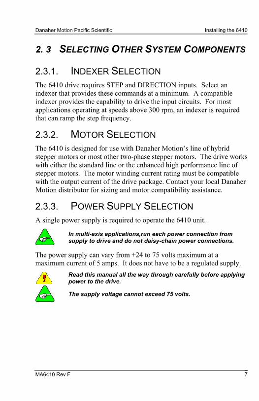
2.3.1. INDEXER SELECTION The 6410 drive requires STEP and DIRECTION inputs. Select an indexer that provides these commands at a minimum. A compatible indexer provides the capability to drive the input circuits. For most applications operating at speeds above 300 rpm, an indexer is required that can ramp the step frequency.
2.3.2. MOTOR SELECTION The 6410 is designed for use with Danaher Motion’s line of hybrid stepper motors or most other two-phase stepper motors. The drive works with either the standard line or the enhanced high performance line of stepper motors. The motor winding current rating must be compatible with the output current of the drive package. Contact your local Danaher Motion distributor for sizing and motor compatibility assistance.
2.3.3. POWER SUPPLY SELECTION A single power supply is required to operate the 6410 unit.
In multi-axis applications,run each power connection from supply to drive and do not daisy-chain power connections.
The power supply can vary from +24 to 75 volts maximum at a maximum current of 5 amps. It does not have to be a regulated supply.
Read this manual all the way through carefully before applying power to the drive.
The supply voltage cannot exceed 75 volts.
Installing the 6410 Danaher Motion Pacific Scientific
8 MA6410 Rev F
2. 4 MOUNTING THE 6410 UNIT
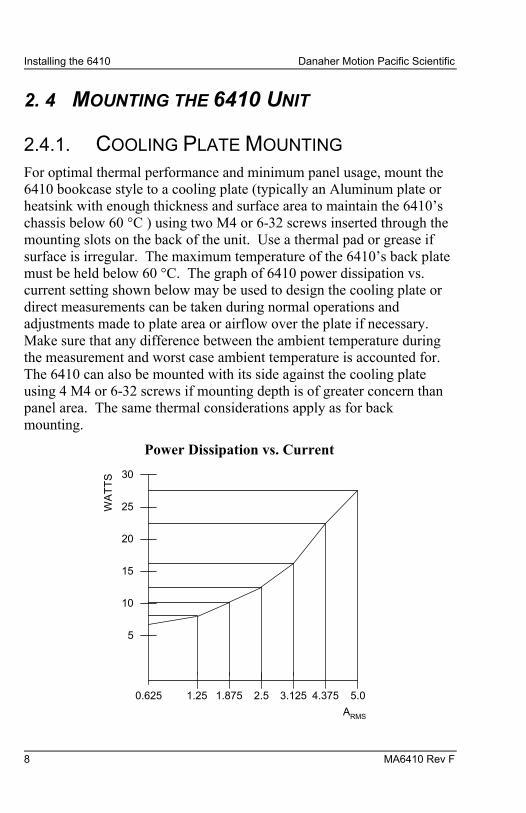
2.4.1. COOLING PLATE MOUNTING For optimal thermal performance and minimum panel usage, mount the 6410 bookcase style to a cooling plate (typically an Aluminum plate or heatsink with enough thickness and surface area to maintain the 6410’s chassis below 60 °C ) using two M4 or 6-32 screws inserted through the mounting slots on the back of the unit. Use a thermal pad or grease if surface is irregular. The maximum temperature of the 6410’s back plate must be held below 60 °C. The graph of 6410 power dissipation vs. current setting shown below may be used to design the cooling plate or direct measurements can be taken during normal operations and adjustments made to plate area or airflow over the plate if necessary. Make sure that any difference between the ambient temperature during the measurement and worst case ambient temperature is accounted for. The 6410 can also be mounted with its side against the cooling plate using 4 M4 or 6-32 screws if mounting depth is of greater concern than panel area. The same thermal considerations apply as for back mounting.
Power Dissipation vs. Current
30
25
20
15
10
5
WA
TT
S
0.625 1.25 1.875 2.5 3.125 4.375 5.0
ARMS

Danaher Motion Pacific Scientific Installing the 6410
MA6410 Rev F 9
2.4.2. HEATSINK MOUNTING If a cooling plate is not provided, the optional heatsink available from Pacific Scientific can be mounted to the side of the 6410 and the combined unit mounted to a panel using the slots on the back of the 6410 as described above (bookcase mounting). With a minimum unobstructed space of four inches above and below the unit, and cooling accomplished solely through convection (no fan), the 6410 can be run at 5 Amps RMS maximum for ambient temperatures of 25°C or less and 2.5 Amps RMS maximum for ambient temperatures of 45°C or less. Using a fan to blow air past the heatsink will increase the allowable current significantly. It is always required that the 6410’s chassis temperature not exceed 60°C. It is best to confirm this by direct measurement with a temperature probe during system operation. Any difference between the ambient temperature during the measurement and the worst case should be added to the measured chassis temperature. The resulting sum must be under 60°C.
2.4.3. PANEL MOUNTING If the 6410 is mounted to a panel with no cooling plate and no heat sink, a minimum unobstructed space of four inches above and below and one inch between the side plate and any other object must be provided. If cooling is accomplished solely through convection air flow (no fan), the unit can be run at 2.5 ARMS maximum if the ambient temperature is 25°C or less and 1.25 ARMS maximum if the ambient temperature is 45°C or less. Again, use of a fan to blow air past the side plate of the 6410 increases the allowable current. The same considerations given above for the optional heatsink apply.
Installing the 6410 Danaher Motion Pacific Scientific
10 MA6410 Rev F
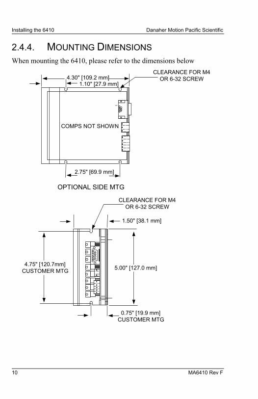
2.4.4. MOUNTING DIMENSIONS When mounting the 6410, please refer to the dimensions below
1
4.30" [109.2 mm]1.10" [27.9 mm]
COMPS NOT SHOWN
CLEARANCE FOR M4OR 6-32 SCREW
2.75" [69.9 mm]
OPTIONAL SIDE MTG
0.75" [19.9 mm]CUSTOMER MTG
5.00" [127.0 mm]
1.50" [38.1 mm]
CLEARANCE FOR M4OR 6-32 SCREW
4.75" [120.7mm]CUSTOMER MTG
Danaher Motion Pacific Scientific Installing the 6410
MA6410 Rev F 11
2.4.5. MOUNTING GUIDELINES Your installation should meet the following guidelines:
− Vertical orientation for the unit. − Flat, solid surface capable of supporting the approximate
1.0 lb. weight (0.5 kg. mass) of the unit. − Free of excessive vibration or shock. − Minimum unobstructed space of 4 inches (10 cm) above and
below the unit. − Maximum ambient temperature of 50° C and maximum 6410
chassis temperature of 60° C.
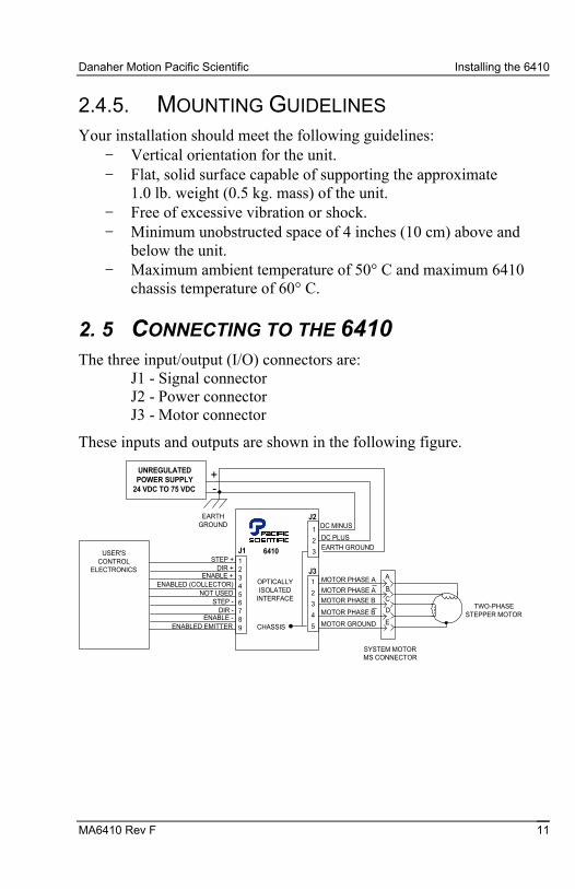
2. 5 CONNECTING TO THE 6410 The three input/output (I/O) connectors are:
J1 - Signal connector J2 - Power connector J3 - Motor connector
These inputs and outputs are shown in the following figure.
123456789
1
2
3
4
5
1
2
3J1
J2
J3
6410
OPTICALLYISOLATED
INTERFACE
CHASSIS
UNREGULATEDPOWER SUPPLY
24 VDC TO 75 VDC
DC MINUS
DC PLUS
EARTH GROUND
+-
EARTHGROUND
ENABLED (COLLECTOR)
STEP +DIR +
ENABLE +
NOT USEDSTEP -
DIR -ENABLE -
ENABLED EMITTER
USER'SCONTROL
ELECTRONICS
MOTOR GROUND
MOTOR PHASE B
MOTOR PHASE B
MOTOR PHASE A
MOTOR PHASE A
SYSTEM MOTORMS CONNECTOR
TWO-PHASESTEPPER MOTOR
A
B
C
D
E

Installing the 6410 Danaher Motion Pacific Scientific
12 MA6410 Rev F
2.5.1. APPLICATION WIRING Wiring sizes, wiring practices and grounding/shielding techniques described in the following section represent common wiring practices and should prove satisfactory in the majority of applications.
Non-standard applications, local electrical codes, special operating conditions, and system configuration wiring needs take precedence over the information included here. Therefore, you may need to wire the driver differently then described here.
2.5.2. NOISE PICKUP REDUCTION
Use shielded and twisted cabling for the signal and power cables to reduce electrical noise.
2.5.3. SHOCK HAZARD REDUCTION
Refer to section 2. 2 for safety information that must be followed to reduce shock hazard.
2. 6 J3 MOTOR CONNECTIONS The J3 motor cable connects the controller to the motor windings and motor case. J3 utilizes a plug-in screw terminal/type connector to simplify assembly and allow quick connect and disconnect.
2.6.1. DANAHER MOTION CABLE
Danaher Motion makes cables that connect directly from J3 to our system motors. To order the cable from Danaher Motion, use the order number SPC-xxx-6410, where “xxx” is the length, in feet (one-foot increments) up to 50 feet. For example, SPC-050 is a cable 50 feet long.
Danaher Motion Pacific Scientific Installing the 6410
MA6410 Rev F 13
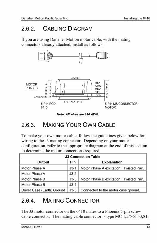
2.6.2. CABLING DIAGRAM
If you are using Danaher Motion motor cable, with the mating connectors already attached, install as follows:
1
5
12345
ABCDE
BLK
REDORG
YELGRN
JACKET
AABB
CASE GND
MOTORPHASES
5-PIN PCD6410
5-PIN MS CONNECTORMOTOR
SPC - XXX - 6410
Note: All wires are #16 AWG.
2.6.3. MAKING YOUR OWN CABLE
To make your own motor cable, follow the guidelines given below for wiring to the J3 mating connector. Depending on your motor configuration, refer to the appropriate diagram at the end of this section to determine the motor connections required.
J3 Connection Table
Output Pin Explanation
Motor Phase A J3-1 Motor Phase A excitation. Twisted Pair.
Motor Phase A J3-2
Motor Phase B J3-3 Motor Phase B excitation. Twisted Pair.
Motor Phase B J3-4
Driver Case (Earth) Ground J3-5 Connected to the motor case ground.
2.6.4. MATING CONNECTOR
The J3 motor connector on the 6410 mates to a Phoenix 5-pin screw cable connector. The mating cable connector is type MC 1,5/5-ST-3,81.
Installing the 6410 Danaher Motion Pacific Scientific
14 MA6410 Rev F
2.6.5. CABLE REQUIREMENTS
The mating connector terminals will accept #16 to #28 AWG wire. However, use #16 AWG or heavier for motor phase excitations.
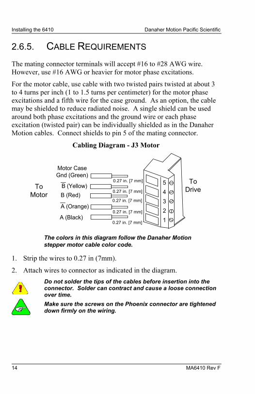
For the motor cable, use cable with two twisted pairs twisted at about 3 to 4 turns per inch (1 to 1.5 turns per centimeter) for the motor phase excitations and a fifth wire for the case ground. As an option, the cable may be shielded to reduce radiated noise. A single shield can be used around both phase excitations and the ground wire or each phase excitation (twisted pair) can be individually shielded as in the Danaher Motion cables. Connect shields to pin 5 of the mating connector.
Cabling Diagram - J3 Motor
5
4
3
2
1
0.27 in. [7 mm]
0.27 in. [7 mm]
0.27 in. [7 mm]
0.27 in. [7 mm]
0.27 in. [7 mm]
Motor CaseGnd (Green)
B (Yellow)
B (Red)
A (Orange)
A (Black)
ToMotor
ToDrive
The colors in this diagram follow the Danaher Motionstepper motor cable color code.
1. Strip the wires to 0.27 in (7mm).
2. Attach wires to connector as indicated in the diagram.
Do not solder the tips of the cables before insertion into the connector. Solder can contract and cause a loose connection over time.
Make sure the screws on the Phoenix connector are tightened down firmly on the wiring.

Danaher Motion Pacific Scientific Installing the 6410
MA6410 Rev F 15
2.6.6. FLYING LEAD CONNECTION The figure below shows the connections required between the 6410 connector J3 and Danaher Motion motors having flying leads. Connections are shown for 4 lead motors, 8 lead motors with paralleled windings, and 8 lead motors with series windings. Wire nuts may be used for the winding connections at the motor end.
RED
YEL
TO J3-1 BLK
ORGTO J3-2
TO J3-3
TO J3-4
DRIVE/EARTHGROUND
TO J3-5
FOUR LEAD MOTOR
RED
YEL
BLK
WHT/BLKTO J3-2
TO J3-3
TO J3-4
DRIVE/EARTHGROUND
TO J3-5
EIGHT LEAD MOTOR CONNECTION IN PARALLEL
WHT/ORG
ORG
TO J3-1
WHT/RED
WHT/YEL
CASE
CASE
RED
YEL
BLK
WHT/BLK
TO J3-2
TO J3-3
TO J3-4
DRIVE/EARTHGROUND
TO J3-5
EIGHT LEAD MOTOR CONNECTION IN SERIES
WHT/ORG
ORG
TO J3-1
WHT/REDWHT/YEL
CASE
A
A
BB
A
B
A
B
A
BA
B
Installing the 6410 Danaher Motion Pacific Scientific
16 MA6410 Rev F
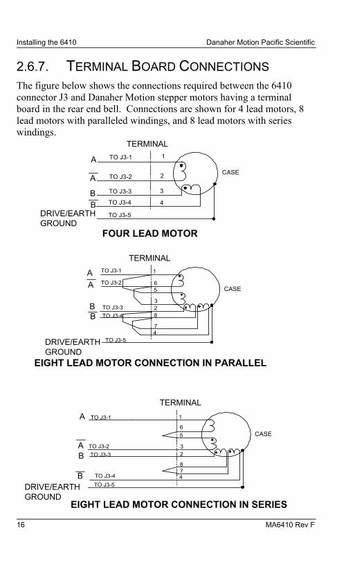
2.6.7. TERMINAL BOARD CONNECTIONS The figure below shows the connections required between the 6410 connector J3 and Danaher Motion stepper motors having a terminal board in the rear end bell. Connections are shown for 4 lead motors, 8 lead motors with paralleled windings, and 8 lead motors with series windings.
3
4
TO J3-1 1
2TO J3-2
TO J3-3
TO J3-4
DRIVE/EARTHGROUND
TO J3-5
FOUR LEAD MOTOR
2
4
1
6TO J3-2
TO J3-3
TO J3-4
DRIVE/EARTHGROUND
TO J3-5
EIGHT LEAD MOTOR CONNECTION IN PARALLEL
5
3
TO J3-1
8
7
CASE
CASE
TO J3-2
TO J3-3
TO J3-4
DRIVE/EARTHGROUND
TO J3-5
EIGHT LEAD MOTOR CONNECTION IN SERIES
TO J3-1
CASE
A
A
BB
A
B
A
B
A
BA
B
TERMINAL
TERMINAL
2
4
1
6
5
3
87
TERMINAL

Danaher Motion Pacific Scientific Installing the 6410
MA6410 Rev F 17
2.6.8. MS CONNECTORS CONNECTION The figure below shows the connections required between the 6410 J3 connector and Danaher Motion stepper motors having MS connectors. Connections are shown for 4 lead motors, 8 lead motors with paralleled windings, and 8 lead motors with series windings.
C
D
TO J3-1 A
BTO J3-2
TO J3-3
TO J3-4
DRIVE/EARTHGROUND
TO J3-5
FOUR LEAD MOTOR
C
D
A
ETO J3-2
TO J3-3
TO J3-4
DRIVE/EARTHGROUND
TO J3-5
EIGHT LEAD MOTOR CONNECTION IN PARALLEL
F
B
TO J3-1
G
H
CASE
CASE
TO J3-2
TO J3-3
TO J3-4
DRIVE/EARTHGROUND
TO J3-5
EIGHT LEAD MOTOR CONNECTION IN SERIES
TO J3-1
CASE
A
A
BB
A
B
A
B
A
BA
B
MS CONNECTOR
C
D
A
E
F
B
GH
MS CONNECTOR
MS CONNECTOR
M
M
Installing the 6410 Danaher Motion Pacific Scientific
18 MA6410 Rev F
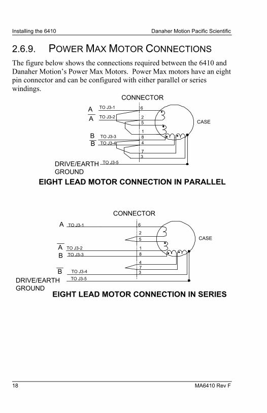
2.6.9. POWER MAX MOTOR CONNECTIONS The figure below shows the connections required between the 6410 and Danaher Motion’s Power Max Motors. Power Max motors have an eight pin connector and can be configured with either parallel or series windings.
8
6
2TO J3-2
TO J3-3
TO J3-4
DRIVE/EARTHGROUND
TO J3-5
EIGHT LEAD MOTOR CONNECTION IN PARALLEL
5
1
TO J3-1
4
7
CASE
TO J3-2
TO J3-3
TO J3-4
DRIVE/EARTHGROUND
TO J3-5
EIGHT LEAD MOTOR CONNECTION IN SERIES
TO J3-1
CASE
A
B
A
B
A
BA
B
CONNECTOR
8
3
6
2
5
1
47
CONNECTOR
3
Danaher Motion Pacific Scientific Installing the 6410
MA6410 Rev F 19
2. 7 J2 POWER CONNECTOR
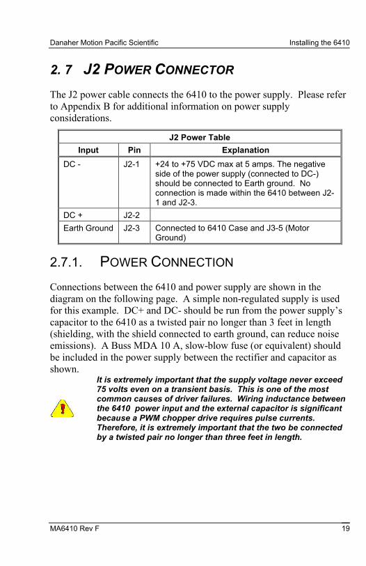
The J2 power cable connects the 6410 to the power supply. Please refer to Appendix B for additional information on power supply considerations.
J2 Power Table
Input Pin Explanation
DC - J2-1 +24 to +75 VDC max at 5 amps. The negative side of the power supply (connected to DC-) should be connected to Earth ground. No connection is made within the 6410 between J2-1 and J2-3.
DC + J2-2
Earth Ground J2-3 Connected to 6410 Case and J3-5 (Motor Ground)
2.7.1. POWER CONNECTION
Connections between the 6410 and power supply are shown in the diagram on the following page. A simple non-regulated supply is used for this example. DC+ and DC- should be run from the power supply’s capacitor to the 6410 as a twisted pair no longer than 3 feet in length (shielding, with the shield connected to earth ground, can reduce noise emissions). A Buss MDA 10 A, slow-blow fuse (or equivalent) should be included in the power supply between the rectifier and capacitor as shown.
It is extremely important that the supply voltage never exceed 75 volts even on a transient basis. This is one of the most common causes of driver failures. Wiring inductance between the 6410 power input and the external capacitor is significant because a PWM chopper drive requires pulse currents. Therefore, it is extremely important that the two be connected by a twisted pair no longer than three feet in length.

Installing the 6410 Danaher Motion Pacific Scientific
20 MA6410 Rev F
2.7.2. CONNECTION DIAGRAM
AC IN
EARTHGROUND
BUSSMDA 10FUSE TWISTED
J2
213
J3
J1
3 FEET MAX
SINGLE AXIS
AC IN
EARTHGROUND
BUSSMDA 10FUSE TWISTED
J2
213
J3
J1
3 FEET MAX
BUSSMDA 10FUSE TWISTED
J2
213
J3
J1
MULTI-AXES
TO OTHER AXES
2.7.3. CABLE REQUIREMENTS
Use #16 AWG for the power supply cable. Use cable twisted at about 3 to 4 turns per inch (1 to 1.5 turns per centimeter).

Danaher Motion Pacific Scientific Installing the 6410
MA6410 Rev F 21
2.7.4. CABLE DIAGRAM - J2 POWER CABLE
3
2
1
Black (DC -)
White (DC +)
Green (Earth Ground)
3. Strip the wires to 0.27 in (7mm).
4. Attach wires to connector as indicated in the diagram.
Do not solder the tips of the cables before insertion into the connector. Solder can contract and cause a loose connection over time.
Make sure the screws on the Phoenix connector are tightened down firmly on the wiring.
2. 8 J1 SIGNAL INTERFACE CONNECTION The J1 signal interface accepts step,direction and enable signals from an indexer or other source and outputs an enabled signal which indicates the 6410 is applying current to the motor windings.
J1 Signal Table
Input/Output Pin Explanation
STEP + J1-1 Input used to command motor rotation. See figure at the end of the table for circuit and timing information.
DIR + J1-2 Input that determines the direction of motor rotation. If standard motor wiring is followed, the motor will turn clockwise if the opto current is zero. The sense of the DIR + input can be reversed by reversing the connection of either (but not both) motor phase connectors (i.e. switching A
& A A OR B & B ). Refer to the figure at the end of the table for timing and circuit information.

Installing the 6410 Danaher Motion Pacific Scientific
22 MA6410 Rev F
J1 Signal Table
Input/Output Pin Explanation
ENABLE + J1-3 Input used to enable or disable the 6410’s power stage. With the J6 5-6 jumper out (factory default) the power stage is enabled if the opto current is zero and disabled if the opto is driven. Inserting the jumper reverses this functionality. See figure at the end of the table for circuit information. There is a delay of approximately 500 ms after enabling the driver and the power stage becoming active.
Enabled Collector
J1-4 Output. Collector of transistor that is on when the 6410’s power stage is active. See figure at the end of the table for circuit information.
J1-5 Not used.
STEP - J1-6 Input used to command motor rotation. See figure at the end of the table for circuit and timing information.
DIR - J1-7 Input that determines the direction of motor rotation. If standard motor wiring is followed, the motor will turn clockwise if the opto current is zero. The sense of the DIR + input can be reversed by reversing the connection of either (but not both) motor phase connectors (i.e. switching A & A OR B & B). Refer to the figure at the end of the table for timing and circuit information.
ENABLE - J1-8 Input used to enable or disable the 6410’s power stage. With the J6 5-6 jumper out (factory default) the power stage is enabled if the opto current is zero and disabled if the opto is driven. Inserting the jumper reverses this functionality. See figure at the end of the table for circuit information. There is a delay of approximately 500 ms after enabling the driver and the power stage becoming active.
Enabled Emitter J1-9 Output. Emitter of transistor that is on when the 6410’s power stage is active. See figure at the end of the table for timing and circuit information.
Note: All inputs and outputs are optically isolated.

Danaher Motion Pacific Scientific Installing the 6410
MA6410 Rev F 23
2.8.1. TYPICAL INTERFACE
The next figure shows a typical interface between the user’s electronics and the 6410. The TTL gates should have totem pole outputs and be capable of sinking at least 10.0 mA at 0.4 volts.
2.8.2. INTERFACE DIAGRAM
TLP 2601
4642.21 k
STEP
STEP
+
-
1
6
J1
6410STEPPERDRIVE
USER'SCONTROLELECTRONICS
+5 VDCTTL
TLP 621
1 k
DIR
DIR
+
-
2
7TTL
TLP 621
1 k
ENABLE
ENABLE
+
-
3
8TTL
4
9
TLP 621 5 VDC
DRIVER_ENABLED
ENABLED (COLLECTOR)
ENABLED (EMITTER)
STEPINPUT
- MOTION OCCURSON THIS EDGE
250 NS MIN (1US MIN WITHSTEP FILTER ENABLED)
DIRECTIONINPUT
SETUP TIME50 US MIN
DIRECTION DATAMUST BE STABLEOVER THIS INTERVAL
Installing the 6410 Danaher Motion Pacific Scientific
24 MA6410 Rev F
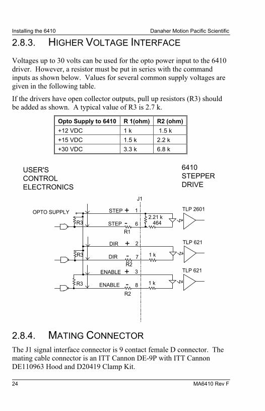
2.8.3. HIGHER VOLTAGE INTERFACE
Voltages up to 30 volts can be used for the opto power input to the 6410 driver. However, a resistor must be put in series with the command inputs as shown below. Values for several common supply voltages are given in the following table.
If the drivers have open collector outputs, pull up resistors (R3) should be added as shown. A typical value of R3 is 2.7 k.
Opto Supply to 6410 R 1(ohm) R2 (ohm)
+12 VDC 1 k 1.5 k
+15 VDC 1.5 k 2.2 k
+30 VDC 3.3 k 6.8 k
TLP 2601
4642.21 k
STEP
STEP
+
-
1
6
J1
6410STEPPERDRIVE
USER'SCONTROLELECTRONICS
OPTO SUPPLY
TLP 621
1 k
DIR
DIR
+
-
2
7
TLP 621
1 k
ENABLE
ENABLE
+
-
3
8
R3
R3
R3
R1
R2
R2
2.8.4. MATING CONNECTOR The J1 signal interface connector is 9 contact female D connector. The mating cable connector is an ITT Cannon DE-9P with ITT Cannon DE110963 Hood and D20419 Clamp Kit.

Danaher Motion Pacific Scientific Powering Up the 6410 Driver
MA6410 Rev F 25
3. POWERING UP THE 6410 DRIVER This chapter explains how to power up the 6410 driver after installation. Topics covered are sSetting up functions using switch S1 and Jumper J6 and testing the installation. This section is intended to familiarize the 6410 user with the hardware adjustments and settings required to power up and operate the 6410 driver.
3. 1 SETTING SWITCH S1 & JUMPER J6 DIP switch S1 and Jumper J6 set step size, motor current level, mid-range instability ON/OFF, idle current reduction, enable sense, and step filter response time.
3.1.1. LOCATION OF S1
ENABLE SENSE JUMPER IN OPTO ON TO ENABLEOUT OPTO OFF TO ENABLE
DEC JUMPER (SEE SW1 TABLE)IN SELECT DECIMAL STEP SIZES
OUT SELECT BINDARY STEP SIZES
IDLE T JUMPERSELECT IDLE CURRENT
REDUCTION TIME (SEE TABLE)
STEP BW JUMPER IN 500 KHZ MAX STEP RATEOUT 2 MHZ MAX STEP RATE
28
J6
OPEN SW
1
JUMPERS 1-2, 3-4, & 7-8INSTALLED AT FACTORY
PC CARD EDGE
S1 SIDE VIEWFACTORY DEFAULTPOSITIONS SHOWN
OPEN
1 2 3 4 5 6 7 8
SW1 POSITION
CLOSEDCLOSEDCLOSEDCLOSEDOPENOPENOPENOPEN
CLOSEDCLOSEDOPENOPENCLOSEDCLOSEDOPENOPEN
CLOSEDOPENCLOSEDOPENCLOSEDOPENCLOSEDOPEN
6 7 8
MOTORCURRENT
ARMS
5.04.3753.7503.1252.5
1.8751.250.625
SW1 POSITION
CLOSEDCLOSEDCLOSEDCLOSEDOPENOPENOPENOPEN
CLOSEDCLOSEDOPENOPENCLOSEDCLOSEDOPENOPEN
CLOSEDOPENCLOSEDOPENCLOSEDOPENCLOSEDOPEN
1 2 3
STEP SIZE
FULLHALF1/51/101/251/501/1251/250
DECJMPR
IN
DECJMPROUT
HALF1/41/81/161/321/641/1281/256
SW1POSITION 4
CLOSEDOPEN
DIGITAL ELECTRONIC DUMPING
DISABLEDENABLED
SW1POSITION 5
CLOSEDOPENCLOSEDOPEN
IDLE-TJUMPER
ININOUTOUT
IDLE CURRENTREDUCTION
DISABLED0.1 SEC DELAY0.05 SEC DELAY1.0 SEC DELAY

Powering Up the 6410 Driver Danaher Motion Pacific Scientific
26 MA6410 Rev F
Definition
The step size sets the amount of rotation per input step. Fifteen step sizes are available using Jumper J6 position 3-4 and DIP switch S1 positions 1-3 as shown. For all Pacific Scientific stepper motors and all 1.8° step motors, step size can be converted to steps per rotation using the following table:
Decimal Binary
Full 200 Half 400
Half 400 1/4 800
1/5 1,000 1/8 1,600
1/10 2,000 1/16 3,200
1/25 5,000 1/32 6,400
1/50 10,000 1/64 12,800
1/125 25,000 1/128 25,600
1/250 50,000 1/256 51,200
Benefits
Selecting a microstep size of 1/4 or smaller results in: higher resolution smoother low speed operation ability to operate in low-speed resonance regions
3.1.2. MID-RANGE INSTABILITY CONTROL
Definition
Mid-range frequency instability and the resulting loss of torque occurs in any step motor/drive system due to the motor back EMF modulating the motor winding currents at certain speeds. Mid-range instability can be explained as a region of potential instability that occurs as a result of the electronic, magnetic, and mechanical characteristics of any stepping motor system. The circuitry used to control this phenomenon does so by advancing or delaying the switching of the output current with respect to the incoming pulse train. This should be taken into account if the user is attempting to employ pulse placement techniques.

Danaher Motion Pacific Scientific Powering Up the 6410 Driver
MA6410 Rev F 27
Enable the mid-range instability control function by placing DIP switch S1 position 4 in the open position as shown. This is the default position and should be used for most applications if your application is affected by loss of torque at mid-range speeds. If pulse placement techniques are being used, disable the mid-range instability control function by placing DIP switch S1 position 4 in the open position.
Benefit
This feature controls torque loss at mid-range speeds. When enabled, the motor maintains torque at mid-range operation, provided the torque load does not exceed motor torque ratings.
3.1.3. IDLE CURRENT REDUCTION
Definition
The Idle Current Reduction (ICR) function reduces the phase current at times when no motion is commanded. Motor current is reduced when no step commands are received for a given time. This time can be set to 0.05 seconds, 0.1 seconds or 1.0 second. Current to both motor windings is reduced by one-half.
The ICR function can be enabled/disabled and the time delay between the last step command and current reduction can be set to 50 ms, 0.1 seconds, or 1.0 second using DIP switch S1 position 5 and Jumper J6 position 7-8. With the jumper installed (factory default), ICR is disabled when DIP Switch S1 position 5 is in the closed position and enabled with a delay of 0.1 second (current is reduced by 50% when no step command is received for 0.1 second when the switch is open. With the jumper removed, ICR is enabled and the delay can be set to 0.05 second or 1.0 second by placing DIP Switch S1 position 5 in the closed or open position respectively.
When ICR is active, both the holding torque generated by the motor and the motor stiffness around the holding position are reduced by approximately 50%.
Benefits
The ICR function reduces motor and drive heating during stand-by operation
Powering Up the 6410 Driver Danaher Motion Pacific Scientific
28 MA6410 Rev F
3.1.4. SETTING MOTOR CURRENT
Motor current can be set using DIP Switch S1 positions 6, 7, and 8 as shown. Current should be compatible with motor current ratings.
Power dissipation in the 6410 driver increases as the output current is increased, so that more cooling is required at high motor currents.
3.1.5. ENABLE SENSE CONTROL
The polarity of the enable input can be changed using Jumper J6 position 5-6. With the jumper removed (factory default), the driver is enabled when the enable input is not driven and disabled when driven (current flows in enable opto). This allows the 6410 to be used with no connection to the enable input. With the J6 5-6 jumper installed, the enable input must be driven (current in opto) for the 6410 power stage to be enabled.
3.1.6. STEP BANDWIDTH ADJUSTMENT
A digital filter can be enabled which reduces susceptibility to noise on the step input at the expense of a lower limit on maximum step frequency. With Jumper J6 positions 1-2 installed (factory default) the filter is enabled and step pulses must have a minimum width of one microsecond. Pulses less than 0.5 microseconds in width will be rejected. With the filter disabled, Jumper J6 position 1-2 removed, step pulses must be a minimum of 0.25 microseconds wide. Therefore, the maximum step frequency is 500 kHz with the filter enabled and 2 MHz with the filter disabled.

Danaher Motion Pacific Scientific Powering Up the 6410 Driver
MA6410 Rev F 29
3. 2 TESTING THE INSTALLATION After installing the 6410 as described in Chapter 2, test your installation to verify that the 6410 is installed properly and was not damaged during shipment.
Perform this initial power up with the motor shaft disconnected from the load. Improper wiring or undiscovered shipping damage could result in undesired motor motion. Be prepared to remove power if excessive motion occurs.
1 2 3 4 5 6 7 8ON
1. Check all wiring and mounting to verify correct installation.
2. With the power Off, check that S1 is set as follows (factory default settings):
These settings reflect the following: Step size of 1/25 Mid-range instability enabled Idle current reduction enabled 5 ARMS motor current
If the motor is rated at less than 5 ARMS winding current, set positions 6, 7, & 8 accordingly.
Make sure the power is off before proceeding!
3. Check that Jumper J6 is set as follows:
28
J6
These settings reflect the following:
Idle Current Reduction Enabled (0.1 second delay) 6410 enabled without enable input driven Decimal step size selected Step input filter enabled
4. Switch On power.

Powering Up the 6410 Driver Danaher Motion Pacific Scientific
30 MA6410 Rev F
3.2.1. SIGNALS TEST
1. Verify that the motor has holding torque by attempting to rotate the motor shaft. The energized motor shaft is either immovable or is resistant to rotation.
2. Input a step command and verify that the motor moves.
3. Reverse the polarity of the DIRECTION signal and step the motor. The direction of rotation should change.
3.2.2. GETTING HELP
If you need further assistance with your installation, please contact your local distributor.

Danaher Motion Pacific Scientific Maintenance & Troubleshooting
MA6410 Rev F 31
4. MAINTENANCE & TROUBLESHOOTING
This chapter covers maintenance and troubleshooting of the 6410 unit.
4. 1 MAINTAINING THE 6410 DRIVER The 6410 drivers are designed for minimum maintenance. The following cleaning procedures performed as needed will minimize problems due to dust and dirt build-up. Remove superficial dust and dirt from the unit using clean, dry, low-pressure air.
4. 2 TROUBLESHOOTING THE 6410 DRIVER The 6410 has an “enabled” output which is on when the driver is enabled and off when the driver is disabled or faulted due to any of the following:
Output overcurrent (line-to-line or line-to-neutral short) Bus overvoltage Low voltage supply out of tolerance.
Use the troubleshooting table and the simple circuit to diagnose and correct most problems.
4.2.1. TROUBLESHOOTING TABLE SYMPTOM CORRECTIVE ACTION
Motor produces no torque, Meter read high.
Ensure that the J6 5-6 jumper is out, or if in, that the enable input opto is driven with at least 3 mA. Disconnect the motor cable and cycle the J2 power supply Off and On.. If the meter reads low, check motor cable and motor for shorts across the windings or between the windings and the motor case.
Check that the J2 power supply voltage is ≥ 24 volts and ≤ 75 VDC. If possible, check with an oscilloscope to verify that this is true on a transient basis.
Motor produces no torque, meter reads low
Verify that DIP Switch S1 position 6, 7, and 8 (current select) are set correctly. Re-check that the motor cable is wired correctly and properly plugged into the driver.

Maintenance & Troubleshooting Danaher Motion Pacific Scientific
32 MA6410 Rev F
SYMPTOM CORRECTIVE ACTION
Motor produces torque but does not turn.
Make sure that the STEP input is switching and meets specified electrical and timing requirements.
Motor rotates in the wrong direction
Check polarity of the DIRECTION input. Also, check that the DIRECTION input satisfies the specified electrical and timing requirements.Reverse the A and /A motor phases.
Motor does not reach expected position
Check that the step size setting of the drive is the same as the step size setting of the indexer. Verify that the motor does not stall. If it does: 1. Re-check sizing calculations. Be sure that the power
supply voltage is high enough for the required torque vs. speed curve.
2. Use a finer step size to avoid low-speed resonance problems.
3. Enable Mid-Band Instability Compensation (S1 position 4 OFF).
Check that the STEP and DIRECTION Inputs satisfy all electrical and timing requirements.
If you cannot correct the driver problem, or if it is defective, return it to Danaher Motion for repair or replacement. Shipment of your driver or motor to Danaher Motion constitutes authorization to repair the unit.
4.2.2. SIMPLE CIRCUIT DIAGRAM
6410
J1-9
J1-4
Meter +
Meter -4.7 k
User Power Supply5 VDC at 1 mA
Note: High = 5 VDC Low = < 1 VDC
If you suspect that the 6410 driver has been damaged, DO NOT simply replace it with another and apply power. Re-check the power supply design and verify that it meets all requirements. Improper supply design is the most common cause for damaged drivers.
Danaher Motion Pacific Scientific Appendix A Specifications
MA6410 Rev F 33
APPENDIX A SPECIFICATIONS
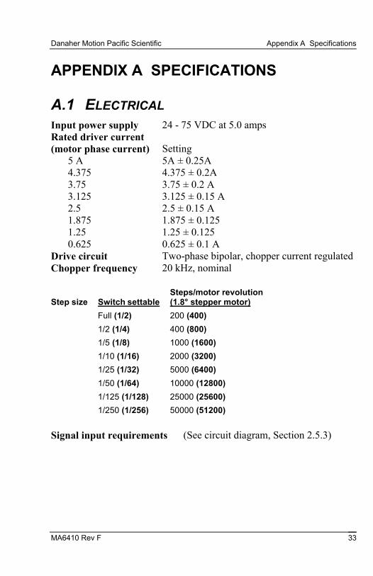
A.1 ELECTRICAL Input power supply 24 - 75 VDC at 5.0 amps Rated driver current (motor phase current)
Setting
5 A 5A ± 0.25A 4.375 4.375 ± 0.2A 3.75 3.75 ± 0.2 A 3.125 3.125 ± 0.15 A 2.5 2.5 ± 0.15 A 1.875 1.875 ± 0.125 1.25 1.25 ± 0.125 0.625 0.625 ± 0.1 A
Drive circuit Two-phase bipolar, chopper current regulated Chopper frequency 20 kHz, nominal Step size
Switch settable
Steps/motor revolution (1.8° stepper motor)
Full (1/2) 200 (400)
1/2 (1/4) 400 (800)
1/5 (1/8) 1000 (1600)
1/10 (1/16) 2000 (3200)
1/25 (1/32) 5000 (6400)
1/50 (1/64) 10000 (12800)
1/125 (1/128) 25000 (25600)
1/250 (1/256) 50000 (51200)
Signal input requirements (See circuit diagram, Section 2.5.3)

Appendix A Specifications Danaher Motion Pacific Scientific
34 MA6410 Rev F
Optically Isolated Inputs
Input
Min Input Current - Opto ON
Max Input Current
Max Reverse Voltage (Input to J1-9)
J1-1, J1-6 - Step 5.5 mA 10 mA 5 volts
J1-2, J1-7 - Direction 3.0 mA 4.5 mA 5 volts
J1-3, J1-7 - Enable 3.0 mA 4.5 mA 5 volts
Signal output characteristics (See circuit diagram, Section 2.5.3)
J1-4, J1-9 Enabled
(Optically isolated NPN transistor with open collector and open emitter)Maximum low level voltage while sinking 2 mA: 0.5 volts
Maximum step rate 2 MHz with step filter disabled 500 kHz with step filter enabled
Step/Direction timing requirements
The figure below show the required timing relationship between the STEP and DIRECTION inputs:
STEPINPUT
- MOTION OCCURSON THIS EDGE
250 NS MIN (1US MIN WITHSTEP FILTER ENABLED)
DIRECTIONINPUT
SETUP TIME50 US MIN
DIRECTION DATAMUST BE STABLEOVER THIS INTERVAL
Minimum ramp time for step rate (Accel/Decel)
50 milliseconds (This restriction only applies with mid-band stability control circuit enabled

Danaher Motion Pacific Scientific Appendix A Specifications
MA6410 Rev F 35
Driver state generator transition delay relative to input step
1. With mid-band stability control circuit enabled, at pulse frequencies less than 500 full steps/sec, delay is less than 500 µsec. At frequencies greater than 500 full steps/sec, delay is less than 270° of the input pulse period.
2. With mid-band stability control circuit disabled, delay is less than 10 µsec at all step frequencies.
A.2 ENVIRONMENTAL
Operating Temperature Full rated current 0 to 50° C ambient air with or without cover provided chassis properly mounted so as not to exceed 60° C.
Storage temperature -55° C to +70° C
Maximum chassis temperature 60° C
For optimal thermal performance, mount the 6410 chassis (back or side) to a cooling plate or heatsink. Use a thermal pad or grease if surface is irregular. A fan or idle current reduction may be employed to keep chassis below 60° C.
Humidity Range 10 to 90%, non-condensing Convection Cooling (6410 not mounted on cooling plate)
With optional heat sink Full rating (5 A) at 25°C Ambient 2.5 A max at 45° C Ambient
Without heat sink 2.5 A max at 25°C Ambient 1.25 A max at 45° C Ambient

Appendix A Specifications Danaher Motion Pacific Scientific
36 MA6410 Rev F
A.3 MECHANICAL Dimensions Refer to Section 2 Weight 1.0 lb nominal Connectors
Power Supply Phoenix MCI, 5/3-G-#,81 connector. Mating connector: Phoenix MCI, 5/3-ST-3,81.
Signal 9 contact female D connector, Mating connector: ITT Cannon DE-9P with ITT Cannon DE110963 Hood and D20419 Clamp Kit.
Motor Phoenix MCI, 5/5-ST-3,81 connector. Mating connector: Phoenix MCI, 5/5-ST-3,81.
A.4 6410 PART NUMBER TABLE Part Danaher Motion Order # Comment
Stepper Driver 6410 Connector Kit 9-pin D connector ^ 5-pin Phoenix ^
106-641000-01 3-pin Phoenix
Installation and Hardware Manual
903-641020-00 MA6410
Motor Cable
SPC-xxx-6410
xxx represents length in feet; for example, SPC-005 is a cable 5 feet long. For lengths over 50 feet contact Danaher Motion. The connectors are MS on the motor end and Phoenix on the driver end to connect to Danaher Motion motors.

Danaher Motion Pacific Scientific Appendix B Power Supply Considerations
MA6410 Rev F 37
APPENDIX B POWER SUPPLY CONSIDERATIONS
B.1 BRIDGE, CAPACITOR POWER SUPPLY The figure below shows the full-wave-bridge, capacitor-input configuration most commonly used to power one or more 6410 driver modules. A single transformer provides isolation and transforms the AC input voltage to a level that, when rectified, provides the desired DC bus voltage. Fusing should be between the rectifier and individual bus capacitors. This allows fuse size to be based upon the current requirements of a single module to provides the greatest protection. The capacitors must be connected to the 6410 DC+ and DC- inputs using twisted pairs no longer than three feet in length as shown to control winding inductive effects. A regen clamp to absorb power transfered from the motor to the 6410(s) is sometimes required. This section provides selection guidelines for the power supply components.
B.1.1 BLOCK DIAGRAM
115 VAC
EARTH / SAFETYGROUND
TRANSFORMER
RECTIFIER
75 V MAX
32
1
32
1
TWISTED +BLEEDERRESISTOR
BUSCAP
FUSE
BUSMDA1
0
REGENZENER 3 FEET MAX
Appendix B Power Supply Considerations Danaher Motion Pacific Scientific
38 MA6410 Rev F
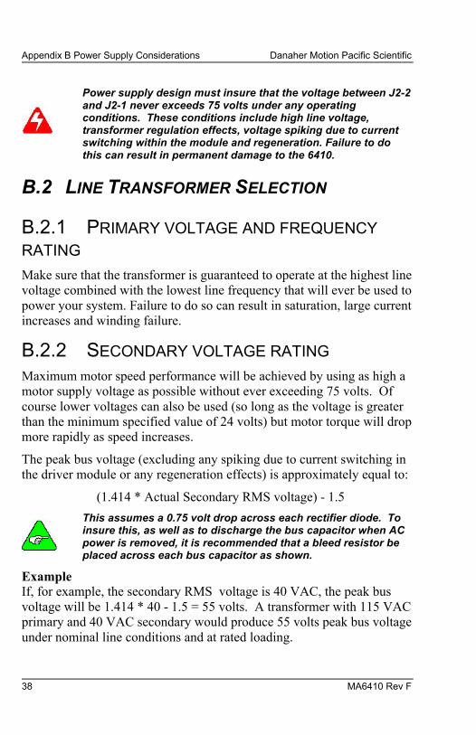
Power supply design must insure that the voltage between J2-2 and J2-1 never exceeds 75 volts under any operating conditions. These conditions include high line voltage, transformer regulation effects, voltage spiking due to current switching within the module and regeneration. Failure to do this can result in permanent damage to the 6410.
B.2 LINE TRANSFORMER SELECTION
B.2.1 PRIMARY VOLTAGE AND FREQUENCY
RATING Make sure that the transformer is guaranteed to operate at the highest line voltage combined with the lowest line frequency that will ever be used to power your system. Failure to do so can result in saturation, large current increases and winding failure.
B.2.2 SECONDARY VOLTAGE RATING Maximum motor speed performance will be achieved by using as high a motor supply voltage as possible without ever exceeding 75 volts. Of course lower voltages can also be used (so long as the voltage is greater than the minimum specified value of 24 volts) but motor torque will drop more rapidly as speed increases.
The peak bus voltage (excluding any spiking due to current switching in the driver module or any regeneration effects) is approximately equal to:
(1.414 * Actual Secondary RMS voltage) - 1.5
This assumes a 0.75 volt drop across each rectifier diode. To insure this, as well as to discharge the bus capacitor when AC power is removed, it is recommended that a bleed resistor be placed across each bus capacitor as shown.
Example If, for example, the secondary RMS voltage is 40 VAC, the peak bus voltage will be 1.414 * 40 - 1.5 = 55 volts. A transformer with 115 VAC primary and 40 VAC secondary would produce 55 volts peak bus voltage under nominal line conditions and at rated loading.

Danaher Motion Pacific Scientific Appendix B Power Supply Considerations
MA6410 Rev F 39
However, if the line voltage increases 10% the peak bus voltage increases to:
(1.414 * 1.1 * 40) - 1.5 = 60.7 volts
at rated transformer loading.
Load regulation must also be accounted for when selecting the transformer. Transformers are designed to produce their specified secondary voltage when loaded by their rated current. For currents less than rated, the secondary voltage will increase. Signal Transformer gives the following load regulation data for its line of rectifier transformers:
VA Rating Load Regulation
1 - 100 10%
100 - 350 8%
> 500 5% or less
This means that the secondary voltage of a 100 VA transformer increases 10% over the specified voltage if the load current is reduced from rated current to zero. Since the stepper driver(s) might sometimes be disabled, the full regulation effect as well as maximum line voltage should be considered when selecting the transformer.1
Based upon these considerations, the table below gives the highest allowable rated secondary voltage when using a line with +10% voltage tolerance:
Transformer VA Rating Maximum Rated Secondary Voltage
1 - 100 44.7 VAC
100 - 350 45.5 VAC
> 500 46.8 VAC
1 The VA product is obtained by multiplying the specified secondary voltage (VRMS) by the rated secondary current (ARMS). For example, a 24 VAC transformer with a rated secondary current of 1 A has a VA of 24.

Appendix B Power Supply Considerations Danaher Motion Pacific Scientific
40 MA6410 Rev F
B.2.3 CURRENT RATING
The average current load of the 6410 is a function of the motor used as well as motor speed and torque. To optimize the power supply design, the supply current can be measured using a DC current meter when the motor is producing the highest shaft power. If it is difficult to make this measruement, assume the maximum average load current equals the selected phase current. Thus, if the DIP switch is set for 5 ARMS, assume the maximum average power supply current is 5 amps.
The average transformer secondary current equals the sum of the average currents for all 6410s powered by the supply. Because the transformer supplies pulses of current to charge the “bus” capacitor(s) on the other side of the diode bridge, the rms current is higher than the average current. The transformer should have a rated secondary RMS current of at least 1.8 times the average current.
Example
The transformer used to supply three 6410 driver modules, each set for 5 Amps rms should have a rated secondary rms current of 1.8 * (5 + 5 + 5) = 27 amps or greater.
It is generally not advisable to significantly oversize the transformer because this will increase rectifier surge current during turn on, as well as capacitor ripple current.
B.2.4 RECTIFIER DIODE SELECTION
Voltage Rating
For the bridge rectifier configuration shown, the peak inverse voltage (PIV) equals 1.414 times the secondary RMS voltage. For example, a 40 VRMS secondary will develop 1.414 * 40 = 56.6 PIV across the rectifier diodes. To allow for line variation and spiking, allow at least a 50% safety factor in the diode rating. Therefore, the PIV rating of the rectifier diodes should be at least twice the rated secondary RMS voltage.

Danaher Motion Pacific Scientific Appendix B Power Supply Considerations
MA6410 Rev F 41
Current Rating
Since each diode conducts only on alternate cycles, the average diode current will be half the supply’s average DC current load on the supply. When power is first applied, there is a surge of current to charge the capacitor(s) which must be less than the diode’s peak one cycle surge current (IFSM) rating. Typically, diodes are chosen with an average current rating of at least twice the average current load of the supply. It is often advisable to select diodes with an even greater average current rating because they have lower thermal resistance between junction and case and hence ease heat sinking requirements. It is good design practice to limit the maximum junction temperature to 125 °C. Testing should be done to insure the power-on surge current is within the diode’s IFSM rating.
B.2.5 CAPACITOR SELECTION The table below gives the minimum bus capacitance value for a single 6410 as a function of the current setting and bus voltage. These values give approximately 10% peak-to-peak ripple voltage with a 60 Hz line (increase capacitor values by 20% for use with a 50 Hz line).
Current Setting 30 Volt Bus 50 Volt Bus 70 Volt Bus
5.0 14,000 8300 6000
4.375 12,000 7300 5200
3.75 10,000 6300 4500
3.125 8700 5200 3700
2.5 6900 4200 3000
1.875 5200 3100 2200
1.25 3500 2100 1500
0.625 1700 1000 740
Bus Capacitance in Microfarads
Ripple Current Rating
The bus capacitor’s 120 Hz ripple current rating should equal or exceed the 6410’s current setting. The capacitor’s working voltage rating must exceed the maximum bus voltage under all line, load, and regen conditions. Select a capacitor rated for at least 1.3 times the nominal bus voltage.

Appendix B Power Supply Considerations Danaher Motion Pacific Scientific
42 MA6410 Rev F
Example
Suppose a 6410 is operating at 70 volts and is set for 5 A rms motor current. Assuming a 60 Hz line, a bus capacitor of 6000 microfarads should be used. The capacitor should have a 120 Hz ripple current rating of at least 5 ARMS and a working voltage of at least 1.3 * 70 = 91 volts.
The bus capacitor should be connected to the 6410 using a twisted pair, no longer than 3 feet in length.
B.2.6 FUSE SELECTION
The BUS MDA10 slow blow fuse or equivalent is recommended when the 6410 is set for 5 amps. Fuses from the same family but with proportionally lower current rating can be used with lower current settings.
B.2.7 REGENERATION CONSIDERATIONS
The motor power supply voltage can be “pumped up” when the motor and load are decelerated by the driver. In effect, the motor becomes a generator converting mechanical energy stored in the spinning motor and load inertias into electrical energy. If the mechanical energy is less than the losses in the driver and motor, the supply voltage does not increase. If the mechanical energy is greater than these losses, the supply voltage will increase (be pumped up).
The mechanical energy of a spinning inertia is given by:
E = 3.87 * 10-5 * J * S2
where: E = kinetic energy (joules) J = inertia in oz-in-sec2 S = speed in rpm

Danaher Motion Pacific Scientific Appendix B Power Supply Considerations
MA6410 Rev F 43
Final Voltage
If this energy is converted to electrical energy in the form of charge on the bus capacitor(s), the voltage is:
V = VO2 +
2EC
where: V is the final voltage (after energy transferred to capacitor(s) VO is the initial voltage C is the total capacitance in farads E is the initial kinetic energy in joules
Example
If an unloaded E34 motor (rotor inertia = .035 oz-in-sec2) is rotating at 1500 rpm, the stored energy is:
3.87 * 10-5 * 0.035 * 15002 = 3.0 joules
If all this energy is transferred to a 6800 mf capacitor, initially charged to 70 volts, the voltage on the capacitor after the transfer is equal to 76 volts.
This exceeds the volt maximum specification of the 6410 driver.
In practice, most or all the kinetic energy is dissipated in the motor windings or in the driver power circuitry so that voltage pump-up is oftennot a problem. However, in systems running at high speeds and having large load inertia, the voltage might be pumped up significantly and circuitry must be added to insure that the 75 volt limit is never exceeded.
Regeneration effects should be considered in the presence of high line conditions.

Appendix B Power Supply Considerations Danaher Motion Pacific Scientific
44 MA6410 Rev F
To find out if regenerative energy is a problem, run the system while monitoring the supply voltage with a storage oscilloscope. Alternatively, a simple peak detector made form a diode and a capacitor can be attached to the bus and the peak voltage measured using a digital voltmeter. Start the system with slow deceleration rates and monitor the motor power supply to see if the voltage rises during deceleration. Slowly increase the deceleration rate (shorten the deceleration time) while monitoring the voltage. If regeneration causes the supply voltage to exceed 75 VDC peak, a clamping circuit is required.
Be sure to consider the effect of high line voltage when evaluating this test.
Clamping Circuit
If a clamp is required, a power zener diode can be used as shown in the figure. The maximum zener clamp voltage must not exceed 75 volts.
If a clamp is required, the transformer secondary voltage must be re-checked to insure that the minimum clamp voltage is not exceeded under high line and low load conditions when there is no regeneration. Otherwise, the zener might overheat and fail.
To determine the required diode power rating, start with a 5W device and monitor the zener current with a current probe. Power (in watts) is the average current (in amps) times the zener voltage. Estimate the average current from the oscilloscope trace and compute the power. Select a zener rated slightly higher than the measured power.
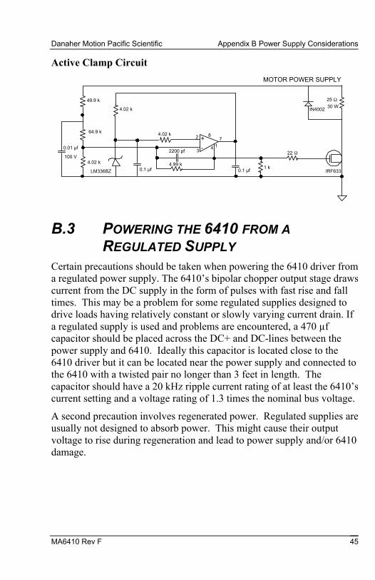
If the average power is too high to be conveniently dissipated in a zener diode, the active voltage clamp circuit shown below can be used instead. Power is dissipated in the 25Ω, 30W resistor if the Motor Power Supply voltage exceeds 75 volts.
Danaher Motion Pacific Scientific Appendix B Power Supply Considerations
MA6410 Rev F 45
Active Clamp Circuit
49.9 k
64.9 k
4.02 k
LM336BZ 0.1 µf
4.02 k
4.02 k
2200 pf
4.99 k
14
782 +
3 -
0.1 µf1 k
22 Ω
IRF633
25 Ω30 W
IN4002
0.01 µf
100 V
MOTOR POWER SUPPLY
B.3 POWERING THE 6410 FROM A
REGULATED SUPPLY Certain precautions should be taken when powering the 6410 driver from a regulated power supply. The 6410’s bipolar chopper output stage draws current from the DC supply in the form of pulses with fast rise and fall times. This may be a problem for some regulated supplies designed to drive loads having relatively constant or slowly varying current drain. If a regulated supply is used and problems are encountered, a 470 µf capacitor should be placed across the DC+ and DC-lines between the power supply and 6410. Ideally this capacitor is located close to the 6410 driver but it can be located near the power supply and connected to the 6410 with a twisted pair no longer than 3 feet in length. The capacitor should have a 20 kHz ripple current rating of at least the 6410’s current setting and a voltage rating of 1.3 times the nominal bus voltage.
A second precaution involves regenerated power. Regulated supplies are usually not designed to absorb power. This might cause their output voltage to rise during regeneration and lead to power supply and/or 6410 damage.

Appendix B Power Supply Considerations Danaher Motion Pacific Scientific
46 MA6410 Rev F
B.3.1 6410(S) POWERED BY REGULATED
SUPPLY
The figure below illustrates powering the 6410 from a regulated supply where both an external capacitor and regenerated power dump circuit are required. The recommended fusing is also shown.
75 V MAX
32
1
32
1
TWISTED +BLEEDERRESISTORFUSE
BUSMDA10
470 µF
REGENZENER
EARTH / SAFETYGROUND
3 FEET MAX
REGULATEDPOWERSUPPLY
+
-
6420
J2
6420
J2
+
B.4 CONTACT INFORMATION
Danaher Motion products are available world-wide through an extensive authorized distributor network. These distributors offer literature, technical assistance and a wide range of models off the shelf for fastest possible delivery.
Danaher Motion sales engineers are conveniently located to provide prompt attention to customers' needs. Call the nearest office listed for ordering and application information or for the address of the closest authorized distributor.
Danaher Motion Customer Support Phone: (815) 226-2222
Email: [email protected] Web: www.DanaherMotion.com


