82
M A 6 4 1 0 6 4 1 0 D r i v e Installation & Hardware Reference Manual

M A 6 4 1 0
6 4 1 0 D r i v e
Installation & Hardware Reference Manual

.

This document is copyrighted by Pacific Scientific Company. It is supplied to the user with the understanding that it will not bereproduced, duplicated, or disclosed in whole or in part withoutthe express written permission of Pacific Scientific Company.
Copyright © 1995, 1996, 1998

.

WAR RANTY AND LIMI TA TION OF LI ABIL ITY
Includes software provided by Pacific Scientific
Pacific Scientific warrants its motors and controllers (“Product(s)”) to the originalpurchaser (the “Customer”), and in the case of original equipment manufacturers or distributors, to their original consumer (the “Customer”) to be free from defects inmaterial and workmanship and to be made in accordance with Customer’sspecifications which have been accepted in writing by Pacific Scientific. In noevent, however, shall Pacific Scientific be liable or have any responsibility undersuch warranty if the Products have been improperly stored, installed, used ormaintained, or if customer has permitted any unauthorized modifications,adjustments, and/or repairs to such Products. Pacific Scientific’s obligationhereunder is limited solely to repairing or replacing (at its option), at its factoryany Products, or parts thereof, which prove to Pacific Scientific’s satisfaction to be defective as a result of defective materials or workmanship, in accordance withPacific Scientific’s stated warranty, provided, however, that written notice ofclaimed defects shall have been given to Pacific Scientific within two (2) yearsafter the date of the product date code that is affixed to the product, and withinthirty (30) days from the date any such defect is first discovered. The products orparts claimed to be defective must be returned to Pacific Scientific, transportationprepaid by Customer, with written specifications of the claimed defect. Evidenceacceptable to Pacific Scientific must be furnished that the claimed defects were not caused by misuse, abuse, or neglect by anyone other than Pacific Scientific.
Pacific Scientific also warrants that each of the Pacific Scientific Motion ControlSoftware Programs (“Program(s)”) will, when delivered, conform to thespecifications therefore set forth in Pacific Scientific’s specifications manual.Customer, however, acknowledges that these Programs are of such complexity and that the Programs are used in such diverse equipment and operating environmentsthat defects unknown to Pacific Scientific may be discovered only after thePrograms have been used by Customer. Customer agrees that as PacificScientific’s sole liability, and as Customer’s sole remedy, Pacific Scientific willcorrect documented failures of the Programs to conform to Pacific Scientific’sspecifications manual. PACIFIC SCIENTIFIC DOES NOT SEPARATELYWARRANT THE RESULTS OF ANY SUCH CORRECTION OR WARRANTTHAT ANY OR ALL FAILURES OR ERRORS WILL BE CORRECTED ORWARRANT THAT THE FUNCTIONS CONTAINED IN PACIFICSCIENTIFIC’S PROGRAMS WILL MEET CUSTOMER’S REQUIREMENTSOR WILL OPERATE IN THE COMBINATIONS SELECTED BY CUSTOMER.This warranty for Programs is contingent upon proper use of the Programs andshall not apply to defects or failure due to: (i) accident, neglect, or misuse; (ii)failure of Customer’s equipment; (iii) the use of software or hardware not provided by Pacific Scientific; (iv) unusual stress caused by Customer’s equipment; or (v)any party other than Pacific Scientific who modifies, adjusts, repairs, adds to,deletes from or services the Programs. This warranty for Programs is valid for aperiod of ninety (90) days from the date Pacific Scientific first delivers thePrograms to Customer.
i

THE FOREGOING WARRANTIES ARE IN LIEU OF ALL OTHERWARRANTIES (EXCEPT AS TO TITLE), WHETHER EXPRESSED ORIMPLIED, INCLUDING WITHOUT LIMITATION, ANY WARRANTY OFMERCHANTABILITY OR OF FITNESS FOR ANY PARTICULAR PURPOSE,AND ARE IN LIEU OF ALL OTHER OBLIGATIONS OR LIABILITIES ONTHE PART OF PACIFIC SCIENTIFIC. PACIFIC SCIENTIFIC’S MAXIMUMLIABILITY WITH RESPECT TO THESE WARRANTIES, ARISING FROMANY CAUSE WHATSOEVER, INCLUDING WITHOUT LIMITATION,BREACH OF CONTRACT, NEGLIGENCE, STRICT LIABILITY, TORT,WARRANTY, PATENT OR COPYRIGHT INFRINGEMENT, SHALL NOTEXCEED THE PRICE SPECIFIED OF THE PRODUCTS OR PROGRAMSGIVING RISE TO THE CLAIM, AND IN NO EVENT SHALL PACIFICSCIENTIFIC BE LIABLE UNDER THESE WARRANTIES OR OTHERWISE,EVEN IF PACIFIC SCIENTIFIC HAS BEEN ADVISED OF THE POSSIBILITYOF SUCH DAMAGES, FOR SPECIAL, INCIDENTAL, OR CONSEQUENTIALDAMAGES, INCLUDING WITHOUT LIMITATION, DAMAGE OR LOSSRESULTING FROM INABILITY TO USE THE PRODUCTS OR PROGRAMS,INCREASED OPERATING COSTS RESULTING FROM A LOSS OF THEPRODUCTS OR PROGRAMS, LOSS OF ANTICIPATED PROFITS, OROTHER SPECIAL, INCIDENTAL, OR CONSEQUENTIAL DAMAGES,WHETHER SIMILAR OR DISSIMILAR, OF ANY NATURE ARISING ORRESULTING FROM THE PURCHASE, INSTALLATION, REMOVAL,REPAIR, OPERATION, USE OR BREAKDOWN OF THE PRODUCTS ORPROGRAMS, OR ANY OTHER CAUSE WHATSOEVER, INCLUDINGNEGLIGENCE.
The foregoing shall also apply to Products, Programs, or parts for the same whichhave been repaired or replaced pursuant to such warranty, and within the period oftime, in accordance with Pacific Scientific’s date of warranty.
No person, including any agent, distributor, or representative of Pacific Scientific,is authorized to make any representation or warranty on behalf of Pacific Scientific concerning any Products or Programs manufactured by Pacific Scientific, except to refer purchasers to this warranty.
ii

Table of Contents.....................................................
1 Overview of the 6410 1-11.1 6410 Definition . . . . . . . . . . . . . . . . . . . . . . . . . . . . . . . 1-1
1.2 Other System Components . . . . . . . . . . . . . . . . . . . . . . . . . 1-4
1.3 How to Use this Manual . . . . . . . . . . . . . . . . . . . . . . . . . . 1-5
1.4 Warranty . . . . . . . . . . . . . . . . . . . . . . . . . . . . . . . . . . 1-5
2 Installing the 6410 2-12.1 Unpacking and Inspecting . . . . . . . . . . . . . . . . . . . . . . . . . 2-1
2.2 Installing and Using the 6410. . . . . . . . . . . . . . . . . . . . . . . . 2-2
2.3 Selecting Other System Components . . . . . . . . . . . . . . . . . . . . 2-3
2.4 Mounting the 6410 Unit . . . . . . . . . . . . . . . . . . . . . . . . . . 2-4
2.5 Connecting to the 6410 . . . . . . . . . . . . . . . . . . . . . . . . . . . 2-7
2.5.1 J3 Motor Connections . . . . . . . . . . . . . . . . . . . . . . . . 2-9
2.5.2 J2 Power Connector. . . . . . . . . . . . . . . . . . . . . . . . . 2-17
2.5.3 J1 Signal Interface Connector . . . . . . . . . . . . . . . . . . . 2-20
3 Powering Up the 6410 Drive 3-13.1 Setting Switch S1 & Jumper J6 . . . . . . . . . . . . . . . . . . . . . . . 3-1
3.1.1 Step Size . . . . . . . . . . . . . . . . . . . . . . . . . . . . . . . 3-3
3.1.2 Digital Electronic Damping Control . . . . . . . . . . . . . . . . . 3-4
3.1.3 Idle Current Reduction . . . . . . . . . . . . . . . . . . . . . . . . 3-5
3.1.4 Setting Motor Current . . . . . . . . . . . . . . . . . . . . . . . . 3-6
3.1.5 Enable Sense Control . . . . . . . . . . . . . . . . . . . . . . . . 3-6
3.1.6 Step Bandwidth Adjustment . . . . . . . . . . . . . . . . . . . . . 3-6
3.2 Testing the Installation . . . . . . . . . . . . . . . . . . . . . . . . . . . 3-7
4 Maintaining/Troubleshooting 4-14.1 Maintaining the 6410 Drive. . . . . . . . . . . . . . . . . . . . . . . . . 4-1
4.2 Troubleshooting the 6410 Drive . . . . . . . . . . . . . . . . . . . . . . 4-1
6410 Installation & Hardware Reference Manual Rev E

Appendix A Specifications A-1
Appendix B Ordering Information B-1
Appendix C Power Supply Considerations C-1
Appendix D CE Installation D-1
Index
Rev E 6410 Installation & Hardware Reference Manual

1 Overview of the 6410
In this chapter This chapter introduces the 6410 stepper drive. Topics coveredare:
• 6410 definition
• Other system components
• System diagram
• How to use this manual
• Warranty information
1.1 6410 Defi ni tion
Overview The Pacific Scientific 6410 converts step and direction inputs intomotor winding currents to control a two-phase stepper motor.Principal features include microstepping and mid-band instabilitycompensation for high resolution and smooth operation throughboth the low speed and mid-band resonance regions.
The output current of the 6410 is dip switch selectable from 5Arms (7.1 A peak in microstep mode) to 0.625A rms (0.88A peak in microstep mode).
The drive supplies regulated phase currents for supply voltagesbetween 24 and 75 Vdc. It is designed for use with PacificScientific’s line of hybrid stepping motors and will work witheither the standard line or the enhanced performance line.
Note: The motor winding must be compatible with the outputcurrent of the drive.
6410 Installation & Hardware Reference Manual - Rev E 1 - 1

Drive features Bipolar chopper drive - patented 4-phase PWM (pulse widthmodulation) chopping electronically controls the motor windingcurrents at 20 KHz frequency. This combines the best ofrecirculating and non-recirculating current regulation producinghigh back EMF rejection with low chopping ripple current.Benefits include: reduced heat dissipation, low electric noise andimproved current control during motor breaking.
Microstepping - switch selectable: full, 1/2, 1/5, 1/10, 1/25, 1/50, 1/125, and 1/250 step capability with decimal jumper installed and 1/2, 1/4, 1/8, 1/16, 1/32, 1/64, 1/128, and 1/256 with decimaljumper removed.
Digital Electronic Damping - patented circuit eliminates torqueand/or motor stalling through mid-speed region that is inherent inall open loop stepper applications.
Short circuit protection circuitry - disables the drive if a shortcircuit occurs on the motor outputs. The drive must be powercycled to clear fault.
MOSFET power devices - allows chopper frequency ofapproximately 20 kHz, eliminating acoustical noise oftenassociated with choppers.
Optically isolated signal interface connection - optical isolationis provided on the step, direction and enable inputs in addition tothe enabled output. The use of optical isolation increases theoptions available for system grounding. The source commandingthe step and direction lines is not tied directly to the motor powersupply ground, allowing the system ground point for these signalsto be made external to the unit.
UL Recognized - 508C (Type R) - File Number E-137798. Thisalso complies with CSA Standard for Process Control Equipment,C22.2 No. 142-M1987.
1 - 2 6410 Installation & Hardware Reference Manual - Rev E

User adjustments
Motor current - sets the motor phase current to 5.0, 4.375, 3.75,3.125, 2.5, 1.875, 1.25, or 0.625 A rms.
using DIPswitch S1
Step size - sets the amount of shaft rotation per step (with thedecimal jumper installed). The settings are full, half, 1/5, 1/10,1/25, 1/50, 1/125, and 1/250 steps per (micro)step. Thiscorresponds to 200, 400, 1000, 2000, 5000, 10,000, 25,000, and50,000 (micro)steps per revolution with a standard 1.8° motor.With the decimal jumper removed, the settings are 1/2, 1/4, 1/8,1/16, 1/32, 1/64, 1/128, and 1/256 steps per (micro) step. Thiscorresponds to 400, 800, 1600, 3200, 6400, 12,800, 25,600, and51,200 (micro) steps per revolution.
Digital Electronic Damping control - enables this patentedfeature which eliminates loss of torque and possible motor stallingconditions when operating at mid-range speeds. This instability isa phenomenon of the electronic, magnetic and mechanicalcharacteristics of a stepping motor system. The compensationcircuit damps mid-range oscillations by advancing or delayingswitching of the output current relative to the incoming pulse train.
Idle current reduction (ICR) - enables or disables idle currentreduction which reduces motor winding current by 50% of itsrated value during motor dwell periods. ICR begins 0.1 secondafter the last input step pulse occurs. This delay can also be set to0.05 seconds or 1 second using a plug-on jumper.
Note: The current will return to 100% at the next step pulse.
using plug-onjumpers
Step filter - when enabled (jumper installed) rejects noise pulseson step input less than 500ηs wide. Useful if maximum step rate is 500 KHz.
Enable sense - allows the polarity of the enable input to bereversed. With the jumper installed, the enable input opto-isolatormust be driven to enable drive. With the jumper removed, enableinput opto-isolator must be driven to disable.
6410 Installation & Hardware Reference Manual - Rev E 1 - 3

Typicalapplications
Typical applications for 6410 include:
• X-Y tables and slides
• Packaging machinery
• Robotics
• Specialty machinery
• Index feed of material
• Labeling machines
1.2 Other Sys tem Com po nents
Overview The other components that, along with the drive, comprise acomplete motor control system are:
• Indexer or step source
• Single power supply (24-75 volts)
• Motor
Installation guidelines for these components are described inChapter 2, “Installing the 6410 Stepper Motor Drive.”
1 - 4 6410 Installation & Hardware Reference Manual - Rev E

System Diagram The following diagram shows an installation of the drive in atypical system.
Note: Your installation may vary from this configuration.
1.3 How to Use this Man ual
This manual contains information and procedures to install, setup,and troubleshoot the 6410 stepper motor drive.
The most effective way to use this manual is to follow theinstallation and power up instructions contained in Chapter 2 andChapter 3.
6410 Installation & Hardware Reference Manual - Rev E 1 - 5

1.4 War ranty
The Pacific Scientific 6410 drives have a two year warrantyagainst defects in material and assembly. Products that have beenmodified by the customer, physically mishandled, or otherwiseabused through miswiring, incorrect switch settings, and so on, are exempt from the warranty plan.
1 - 6 6410 Installation & Hardware Reference Manual - Rev E

2 Installing the 6410
In this chapter This chapter explains how to install the 6410 stepper motor drive.Topics covered are:
• Unpacking and inspecting the 6410
• Installing and using the 6410 unit safely
• Selecting other system components
• Mounting the 6410 in your installation
• Connecting input/output cables
2.1 Un pack ing and In spect ing
Unpackingprocedure
1. Remove the 6410 from the shipping carton. Make sure allpacking materials are removed from the unit.
2. Check the items against the packing list. A label locatedinside the chassis of the unit identifies the unit by modelnumber, serial number, and date code.
Inspectionprocedure
Inspect the unit for any physical damage that may have beensustained during shipment.
If you find damage, either concealed or obvious, contact yourbuyer to make a claim with the shipper. Do this within 10 days of receipt of the unit.
Storing the unit After inspection, store the controller in a clean, dry, place. Thestorage temperature must be between -55 degrees C and 70degrees C. To prevent damage during storage, replace the unit inthe original shipping carton.
6410 Installation and Hardware Reference Manual - Rev E 2 - 1

2.2 In stall ing and Us ing the 6410 Unit Safely
Yourresponsibility
As the user or person applying this unit, you are responsible fordetermining the suitability of this product for any application youintend. In no event will Pacific Scientific Company be responsible or liable for indirect or consequential damage resulting from themisuse of this product.
Note: Read this manual completely to effectively and safelyoperate the 6410 unit.
Warning
The circuits in the 6410 drive are a potential source of severeelectrical shock. Follow the safety guidelines to avoid shock.
Safetyguidelines
To avoid possible personal injury whenever you are working withthe 6410 unit:
• Do not operate the drive without the motor case tied to earthground.
Note: This is normally done by connecting the motor’s caseto J3-5 of the 6410 and connecting J2-3 of the 6410 to earthground.
• Do not make any connections to the internal circuitry. Theinput and output signals are the only safe connection points.
• Always remove power before making or removing connections from the unit.
• Be careful of the J3 motor terminals when disconnected fromthe motor. With the motor disconnected and power applied tothe drive, these terminals have high voltage present, even withthe motor disconnected.
• Do not use the ENABLE input as a safety shutdown. Alwaysremove power to the drive for a safety shutdown.
2 - 2 6410 Installation and Hardware Reference Manual - Rev E

2.3 Se lect ing Other Sys tem Com po nents
Selecting anindexer
The 6410 drive requires STEP and DIRECTION inputs. Select an indexer that provides, as a minimum, these commands. Acompatible indexer will provide the capability to drive the inputcircuits shown in Section 2.5.3. For most applications that operate at speeds above 300 rpm, an indexer that can ramp the stepfrequency is required.
Selecting amotor
The 6410 is designed for use with Pacific Scientific’s line ofhybrid stepper motors or most other 2 phase stepper motors. Thedrive works with either the standard line or the enhanced highperformance line of stepper motors. The motor winding currentrating must be compatible with the output current of the drivepackage.
Refer to the Torque/Speed Curves in the Pacific Scientific“Motion Control Solutions Catalog” or contact your local PacificScientific distributor for sizing and motor compatibility assistance.
Selecting powersupply
A single power supply is required to operate the 6410 unit.
Note: In multi-axis applications, it is preferable to run eachpower connection from supply to drive and not daisy-chain thepower connections.
The power supply can vary from +24 to 75 Volts maximum at amaximum current of 5 amps. It does not have to be a regulatedsupply.
Note: The supply voltage cannot exceed 75 volts.
IMPORTANT NOTE
Important information about the power supply is outlined inSection 2.5.2 and Appendix C. Read these sections carefullybefore applying power to the drive.
6410 Installation and Hardware Reference Manual - Rev E 2 - 3

2.4 Mount ing the 6410 Unit
Cooling platemounting
For optimal thermal performance and minimum panel usage,mount the 6410 bookcase style to a cooling plate (typically anAluminum plate or heatsink with enough thickness and surfacearea to maintain the 6410’s chassis below 60°C ) using two M4 or6-32 screws inserted through the mounting slots on the back of the unit. Use a thermal pad or grease if surface is irregular. Themaximum temperature of the 6410’s back plate must be heldbelow 60°C. The graph of 6410 power dissipation vs. currentsetting shown below may be used to design the cooling plate ordirect measurements can be taken during normal operations andadjustments made to plate area or airflow over the plate ifnecessary. Make sure that any difference between the ambienttemperature during the measurement and worst case ambienttemperature is accounted for. The 6410 can also be mounted withits side against the cooling plate using 4 M4 or 6-32 screws ifmounting depth is of greater concern than panel area. The samethermal considerations apply as for back mounting.
Power dissipationvs. current
2 - 4 6410 Installation and Hardware Reference Manual - Rev E

Heatsinkmounting
If a cooling plate is not provided, the optional heatsink availablefrom Pacific Scientific can be mounted to the side of the 6410 and the combined unit mounted to a panel using the slots on the backof the 6410 as described above (bookcase mounting). With aminimum unobstructed space of four inches above and below theunit, and cooling accomplished solely through convection (no fan), the 6410 can be run at 5 Amps RMS maximum for ambienttemperatures of 25°C or less and 2.5 Amps RMS maximum forambient temperatures of 45°C or less. Using a fan to blow air past the heatsink will increase the allowable current significantly. It isalways required that the 6410’s chassis temperature not exceed60°C. It is best to confirm this by direct measurement with atemperature probe during system operation. Any differencebetween the ambient temperature during the measurement and theworst case should be added to the measured chassis temperature.The resulting sum must be under 60°C.
Panelmounting
If the 6410 is mounted to a panel with no cooling plate and noheat sink, a minimum unobstructed space of four inches above and below and one inch between the side plate and any other objectmust be provided. If cooling is accomplished solely throughconvection air flow (no fan), the unit can be run at 2.5 Amps RMS maximum if the ambient temperature is 25°C or less and 1.25Amps RMS maximum if the ambient temperature is 45°C or less.Again, use of a fan to blow air past the side plate of the 6410 willincrease the allowable current. The same considerations givenabove for the optional heatsink apply.
6410 Installation and Hardware Reference Manual - Rev E 2 - 5

Mountingdimensions
When mounting the 6410, please refer to the dimensions below:
2 - 6 6410 Installation and Hardware Reference Manual - Rev E

Mountingguidelines
Your installation should meet the following guidelines:
• Vertical orientation for the unit.
• Flat, solid surface capable of supporting the approximate1.0 lb. weight (0.5 kg. mass) of the unit.
• Free of excessive vibration or shock.
• Minimum unobstructed space of 4 inches (10 cm) above andbelow the unit.
• Maximum ambient temperature of 50° C and maximum 6410chassis temperature of 60° C.
2.5 Con nect ing to the 6410
Introduction The three input/output (I/O) connectors are:
• J1 - Signal connector
• J2 - Power connector
• J3 - Motor connector
These inputs and outputs are shown on the following page.
6410 Installation and Hardware Reference Manual - Rev E 2 - 7
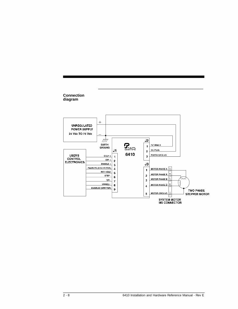
Connectiondiagram
2 - 8 6410 Installation and Hardware Reference Manual - Rev E

Wiring isapplicationspecific
Wiring sizes, wiring practices and grounding/shielding techniquesdescribed in the following section represent common wiringpractices and should prove satisfactory in the majority ofapplications.
Caution
Non-standard applications, local electrical codes, specialoperating conditions, and system configuration wiring needs take precedence over the information included here. Therefore, youmay need to wire the drive differently then described here.
Noise pickupreduction
Use shielded and twisted cabling for the signal and power cablesas described below. This precaution reduces electrical noise.
Shock hazardreduction
Refer to section 2.2 for safety information that must be followedto reduce shock hazard.
2.5.1 J3 Mo tor Con nec tions
Introduction The J3 motor cable connects the controller to the motor windingsand motor case. J3 utilizes a plug-in screw terminal/typeconnector to simplify assembly and allow quick connect anddisconnect.
Pacific Scientificcable
Pacific Scientific makes cables that connect directly from J3 to our system motors. To order the cable from Pacific Scientific, use theorder number SPC-xxx-6410, where “xxx” is the length, in feet(one-foot increments) up to 50 feet. For example, SPC-050 is acable 50 feet long.
6410 Installation and Hardware Reference Manual - Rev E 2 - 9

Pacific Scientificcabling diagram
If you are using Pacific Scientific motor cable, with the matingconnectors already attached, install as follows:
Note: All wires are #16 AWG.
2 - 10 6410 Installation and Hardware Reference Manual - Rev E
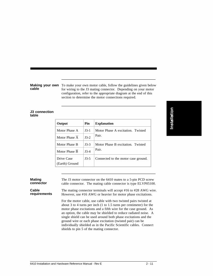
Making your owncable
To make your own motor cable, follow the guidelines given below for wiring to the J3 mating connector. Depending on your motorconfiguration, refer to the appropriate diagram at the end of thissection to determine the motor connections required.
J3 connectiontable
Output Pin Explanation
Motor Phase A J3-1 Motor Phase A excitation. Twisted
Pair.Motor Phase A J3-2
Motor Phase B J3-3 Motor Phase B excitation. Twisted
Pair.Motor Phase B J3-4
Drive Case
(Earth) Ground
J3-5 Connected to the motor case ground.
Mating connector
The J3 motor connector on the 6410 mates to a 5-pin PCD screwcable connector. The mating cable connector is type ELVP05100.
Cablerequirements
The mating connector terminals will accept #16 to #28 AWG wire. However, use #16 AWG or heavier for motor phase excitations.
For the motor cable, use cable with two twisted pairs twisted atabout 3 to 4 turns per inch (1 to 1.5 turns per centimeter) for themotor phase excitations and a fifth wire for the case ground. Asan option, the cable may be shielded to reduce radiated noise. Asingle shield can be used around both phase excitations and theground wire or each phase excitation (twisted pair) can beindividually shielded as in the Pacific Scientific cables. Connectshields to pin 5 of the mating connector.
6410 Installation and Hardware Reference Manual - Rev E 2 - 11

Cabling diagram -J3 motor
Note: The colors in the diagram follow the Pacific Scientificstepper motor cable color code.
Procedure 1. Strip the wires to 0.27 in (7mm).
2. Attach wires to connector as indicated in the diagram.
Note: Make sure the screws on the PCD connector are tighteneddown firmly on the wiring.
Caution
Do not solder the tips of the cables before insertion into theconnector. Solder can contract and cause a loose connectionover time.
2 - 12 6410 Installation and Hardware Reference Manual - Rev E

Flying LeadConnection
The figure below shows the connections required between the6410 connector J3 and Pacific Scientific motors having flyingleads. Connections are shown for 4 lead motors, 8 lead motorswith paralleled windings, and 8 lead motors with series windings.Wire nuts may be used for the winding connections at the motorend.
6410 Installation and Hardware Reference Manual - Rev E 2 - 13

Terminal boardconnections
The figure below shows the connections required between the6410 connector J3 and Pacific Scientific stepper motors having aterminal board in the rear end bell. Connections are shown for 4lead motors, 8 lead motors with paralleled windings, and 8 leadmotors with series windings.
2 - 14 6410 Installation and Hardware Reference Manual - Rev E

MS connectorsconnection
The figure below shows the connections required between the6410 J3 connector and Pacific Scientific stepper motors havingMS connectors. Connections are shown for 4 lead motors, 8 leadmotors with paralleled windings, and 8 lead motors with serieswindings.
6410 Installation and Hardware Reference Manual - Rev E 2 - 15

Power Max motorconnections
The figure below shows the connections required between the6410 and Pacific Scientific Power Max Motors. Power Maxmotors have an eight pin connector and can be configured witheither parallel or series windings.
2 - 16 6410 Installation and Hardware Reference Manual - Rev E

2.5.2 J2 Power Con nec tor
Introduction The J2 power cable connects the 6410 to the power supply. Please refer to Appendix C for additional information on power supplyconsiderations.
J2 power table
Input Pin Explanation
DC - J2-1 +24 to +75 Vdc max at 5 ampsThe negative side of the power supply(connected to DC-) should be connected toEarth ground. No connection is made within the 6410 between J2-1 and J2-3.
DC + J2-2
Earth Ground J2-3 Connected to 6410 Case and J3-5 (MotorGround)
Powerconnection
Connections between the 6410 and power supply are shown in thediagram on the following page. A simple non-regulated supply isused for this example. DC+ and DC- should be run from thepower supply’s capacitor to the 6410 as a twisted pair no longerthan 3 feet in length (shielding, with the shield connected to earthground, can reduce noise emissions). A Buss MDA 10 A,slow-blow fuse (or equivalent) should be included in the powersupply between the rectifier and capacitor as shown.
IMPORTANT NOTE
It is extremely important that the supply voltage never exceed 75volts even on a transient basis. This is one of the most commoncauses of drive failures. Wiring inductance between the 6410power input and the external capacitor is significant because aPWM chopper drive requires pulse currents. Therefore, it isextremely important that the two be connected by a twisted pairno longer than three feet in length.
6410 Installation and Hardware Reference Manual - Rev E 2 - 17

Connectiondiagram
Cablerequirements
Use #16 AWG for the power supply cable. Use cable twisted atabout 3 to 4 turns per inch (1 to 1.5 turns per centimeter).
2 - 18 6410 Installation and Hardware Reference Manual - Rev E

Cable diagram -J2 power cable
Procedure 1. Strip the wires 0.27 inch (7mm).
2. Attach the wires to the connector as indicated in the diagram.
Note: Make sure the screws on the PCD connector aretightened down firmly on the wiring.
Caution
Do not solder the tips of the cables going into the PCDconnector. This can result in a loose connection.
2.5.3 J1 Sig nal In ter face Con nec tion
Introduction The J1 signal interface accepts step,direction and enable signalsfrom an indexer or other source and outputs an enabled signalwhich indicates the 6410 is applying current to the motorwindings.
6410 Installation and Hardware Reference Manual - Rev E 2 - 19

J1 signal table Note: All inputs and outputs are optically isolated.
Input/Output Pin Explanation
STEP + J1-1 Input used to command motor rotation. See figure at
the end of the table for circuit and timing information.
DIR + J1-2 Input that determines the direction of motor rotation. If
standard motor wiring is followed, the motor will turn
clockwise if the opto current is zero. The sense of the
DIR + input can be reversed by reversing the
connection of either (but not both) motor phase
connectors (i.e. switching A & A OR B & B). Refer to
the figure at the end of the table for timing and circuit
information.
ENABLE + J1-3 Input used to enable or disable the 6410’s power stage.
With the J6 5-6 jumper out (factory default) the power
stage is enabled if the opto current is zero and disabled
if the opto is driven. Inserting the jumper reverses this
functionality. See figure at the end of the table for
circuit information. There is a delay of approximately
500 µs after enabling the drive and the power stage
becoming active.
Enabled
Collector
J1-4 Output. Collector of transistor that is on when the
6410’s power stage is active. See figure at the end of
the table for circuit information.
J1-5 Not used.
STEP - J1-6 Input used to command motor rotation. See figure at
the end of the table for circuit and timing information.
2 - 20 6410 Installation and Hardware Reference Manual - Rev E

Table cont’d
Input/Output Pin Explanation
DIR - J1-7 Input that determines the direction of motor rotation. If
standard motor wiring is followed, the motor will turn
clockwise if the opto current is zero. The sense of the
DIR + input can be reversed by reversing the
connection of either (but not both) motor phase
connectors (i.e. switching A & A OR B & B). Refer to
the figure at the end of the table for timing and circuit
information.
ENABLE - J1-8 Input used to enable or disable the 6410’s power stage.
With the J6 5-6 jumper out (factory default) the power
stage is enabled if the opto current is zero and disabled
if the opto is driven. Inserting the jumper reverses this
functionality. See figure at the end of the table for
circuit information. There is a delay of approximately
500 µs after enabling the drive and the power stage
becoming active.
Enabled
Emitter
J1-9 Output. Emitter of transistor that is on when the 6410’s
power stage is active. See figure at the end of the table
for timing and circuit information.
Typicalinterface
The figure on the following page shows a typical interfacebetween the user’s electronics and the 6410. The TTL gatesshould have totem pole outputs and be capable of sinking at least10.0 mA at 0.4 volts.
6410 Installation and Hardware Reference Manual - Rev E 2 - 21

Interfacediagram
2 - 22 6410 Installation and Hardware Reference Manual - Rev E

Higher voltageinterface
Voltages up to 30 volts can be used for the opto power input tothe 6410 drive. However, a resistor must be put in series with thecommand inputs as shown below. Values for several commonsupply voltages are given in the following table.
If the drives have open collector outputs, pull up resistors (R3)should be added as shown. A typical value of R3 is 2.7K.
Opto Supply to 6410 R1 R2
+12 Vdc 1 Kohm 1.5 K
+15 Vdc 1.5 Kohm 2.2 K
+30 Vdc 3.3 Kohms 6.8 K
6410 Installation and Hardware Reference Manual - Rev E 2 - 23

Matingconnector
The J1 signal interface connector is 9 contact female D connector.The mating cable connector is an ITT Cannon DE-9P with ITTCannon DE110963 Hood and D20419 Clamp Kit.
2 - 24 6410 Installation and Hardware Reference Manual - Rev E

3 Powering Up the 6410 Drive
In this chapter This chapter explains how to power up the 6410 drive afterinstallation. Topics covered are:
• Setting up functions using switch S1 and Jumper J6
• Testing the installation
This section is intended to familiarize the 6410 user with thehardware adjustments and settings required to power up andoperate the 6410 drive.
3.1 Set ting Switch S1 & Jumper J6
Introduction DIP switch S1 and Jumper J6 set the following:
• Step size
• Motor current level
• Digital electronic damping ON/OFF
• Idle current reduction
• Enable sense
• Step filter response time
6410 Installation and Hardware Reference Manual - Rev E 3 - 1

Location of S1
3 - 2 6410 Installation and Hardware Reference Manual - Rev E
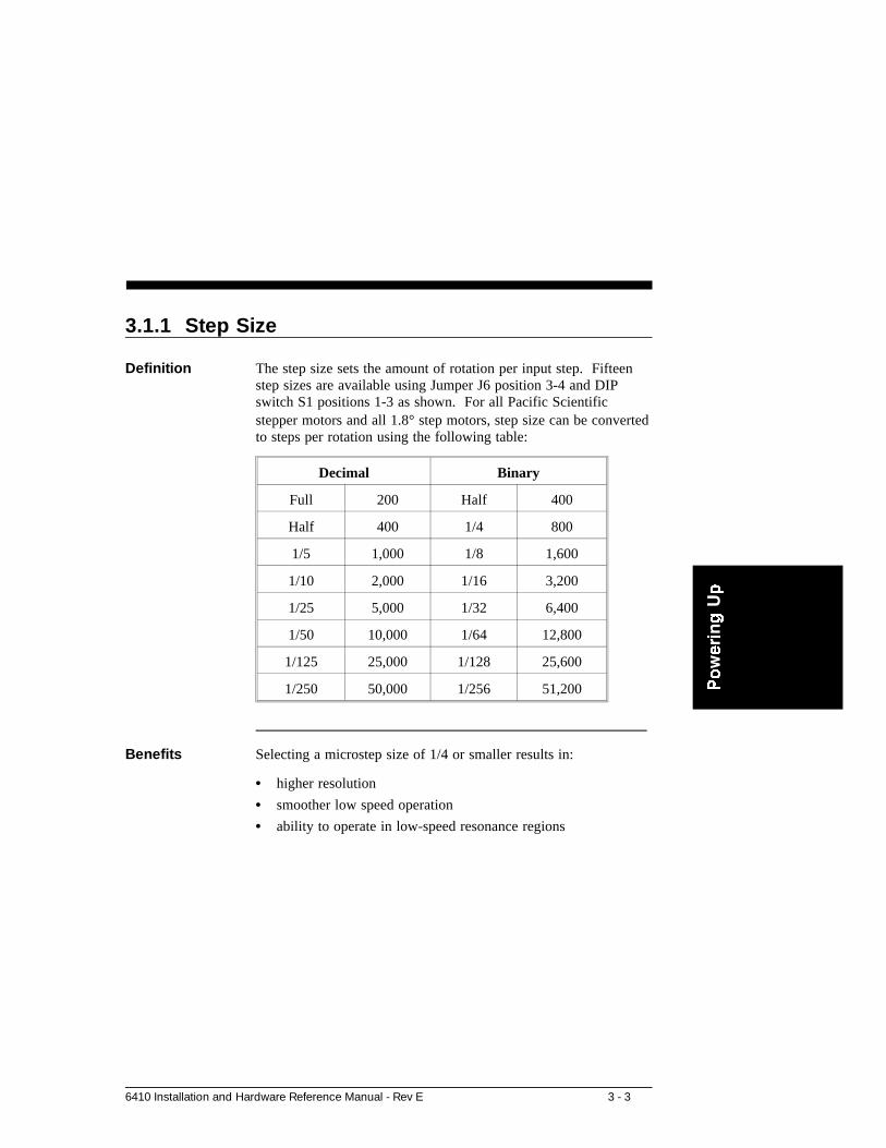
3.1.1 Step Size
Definition The step size sets the amount of rotation per input step. Fifteenstep sizes are available using Jumper J6 position 3-4 and DIPswitch S1 positions 1-3 as shown. For all Pacific Scientificstepper motors and all 1.8° step motors, step size can be converted to steps per rotation using the following table:
Decimal Binary
Full 200 Half 400
Half 400 1/4 800
1/5 1,000 1/8 1,600
1/10 2,000 1/16 3,200
1/25 5,000 1/32 6,400
1/50 10,000 1/64 12,800
1/125 25,000 1/128 25,600
1/250 50,000 1/256 51,200
Benefits Selecting a microstep size of 1/4 or smaller results in:
• higher resolution
• smoother low speed operation
• ability to operate in low-speed resonance regions
6410 Installation and Hardware Reference Manual - Rev E 3 - 3

3.1.2 Digi tal Elec tronic Damp ing Con trol
Definition Mid-speed instability and the resulting loss of torque occurs in any step motor/drive system due to the motor back EMF modulatingthe motor winding currents at certain speeds. Mid-speedinstability can be explained as a region of potential instability thatoccurs as a result of the electronic, magnetic, and mechanicalcharacteristics of any stepping motor system. The circuitry used to control this phenomenon does so by advancing or delaying theswitching of the output current with respect to the incoming pulsetrain. This should be taken into account if the user is attemptingto employ pulse placement techniques.
Enable the digital electronic damping function by placing DIPswitch S1 position 4 in the open position as shown. This is thedefault position and should be used for most applications if yourapplication is affected by loss of torque at mid-range speeds. Ifpulse placement techniques are being used, disable the digitalelectronic damping function by placing DIP switch S1 position 4in the open position.
Benefit This feature controls torque loss at mid-range speeds. Whenenabled, the motor maintains torque at mid-range operation,provided the torque load does not exceed motor torque ratings.
3 - 4 6410 Installation and Hardware Reference Manual - Rev E

3.1.3 Idle Cur rent Re duc tion
Definition The Idle Current Reduction (ICR) function reduces the phasecurrent at times when no motion is commanded. Motor current isreduced when no step commands are received for a given time.This time can be set to 0.05 seconds, 0.1 seconds or 1.0 second.Current to both motor windings is reduced by one-half.
The ICR function can be enabled/disabled and the time delaybetween the last step command and current reduction can be set to 50 ms, 0.1 seconds, or 1.0 second using DIP switch S1 position 5and Jumper J6 position 7-8. With the jumper installed (factorydefault), ICR is disabled when DIP Switch S1 position 5 is in theclosed position and enabled with a delay of 0.1 second (current isreduced by 50% when no step command is received for 0.1 second when the switch is open. With the jumper removed, ICR isenabled and the delay can be set to 0.05 second or 1.0 second byplacing DIP Switch S1 position 5 in the closed or open positionrespectively.
Note: When ICR is active, both the holding torque generated bythe motor and the motor stiffness around the holding position arereduced by approximately 50%.
Benefits The ICR function:
• Reduces motor and drive heating during stand-by operation
6410 Installation and Hardware Reference Manual - Rev E 3 - 5

3.1.4 Set ting Mo tor Cur rent
Motor current can be set using DIP Switch S1 positions 6, 7, and 8 as shown. Current should be compatible with motor currentratings.
Note: Power dissipation in the 6410 drive increases as the output current is increased, so that more cooling is required at highmotor currents.
3.1.5 En able Sense Con trol
The polarity of the enable input can be changed using Jumper J6position 5-6. With the jumper removed (factory default), the drive is enabled when the enable input is not driven and disabled whendriven (current flows in enable opto). This allows the 6410 to beused with no connection to the enable input. With the J6 5-6jumper installed, the enable input must be driven (current in opto)for the 6410 power stage to be enabled.
3.1.6 Step Band width Ad just ment
A digital filter can be enabled which reduces susceptibility tonoise on the step input at the expense of a lower limit onmaximum step frequency. With Jumper J6 positions 1-2 installed(factory default) the filter is enabled and step pulses must have aminimum width of one microsecond. Pulses less than 0.5microseconds in width will be rejected. With the filter disabled,Jumper J6 position 1-2 removed, step pulses must be a minimumof 0.25 microseconds wide. Therefore, the maximum stepfrequency is 500 KHz with the filter enabled and 2 MHz with thefilter disabled.
3 - 6 6410 Installation and Hardware Reference Manual - Rev E

3.2 Test ing the In stal la tion
Background The following procedure verifies that the 6410 is installed properly and that it was not damaged during shipment.
Procedure After installing the 6410 as described in Chapter 2, test yourinstallation as follows.
Warning
Perform this initial power up with the motor shaft disconnectedfrom the load. Improper wiring or undiscovered shippingdamage could result in undesired motor motion. Be prepared toremove power if excessive motion occurs.
Connections test 1. Check all wiring and mounting to verify correct installation.
2. With the power Off, check that S1 is set as follows (factorydefault settings):
These settings reflect the following:
- Step size of 1/25
- Digital electronic damping enabled
- Idle current reduction enabled
- 5 A rms motor current
Warning
If the motor is rated at less than 5 A rms winding current,set positions 6, 7, & 8 accordingly.
6410 Installation and Hardware Reference Manual - Rev E 3 - 7

Procedure cont’d
Warning
Make sure power is removed before proceeding.
3. Check that Jumper J6 is set as follows:
These settings reflect the following:
- Idle Current Reduction Enabled (0.1 second delay)
- 6410 enabled without enable input driven
- Decimal step size selected
- Step input filter enabled
4. Switch On power.
Signals test 1. Verify that the motor has holding torque by attempting torotate the motor shaft. The energized motor shaft is eitherimmovable or is resistant to rotation.
2. Input a step command and verify that the motor moves.
3. Reverse the polarity of the DIRECTION signal and step themotor. The direction of rotation should change.
Getting help If you need further assistance with your installation, please contact your local distributor.
3 - 8 6410 Installation and Hardware Reference Manual - Rev E

4 Maintaining/Troubleshooting
In this chapter This chapter covers maintenance and troubleshooting of the 6410unit.
4.1 Main tain ing the 6410 Drive
Introduction The 6410 drives are designed for minimum maintenance. Thefollowing cleaning procedure, performed as needed, will minimizeproblems due to dust and dirt build-up.
Procedure Remove superficial dust and dirt from the unit using clean, dry,low-pressure air.
4.2 Trou ble shoot ing the 6410 Drive
Introduction The 6410 has an “enabled” output which is on when the drive isenabled and off when the drive is disabled or faulted due to any of the following:
• Output overcurrent (line-to-line or line-to-neutral short)
• Bus overvoltage
• Low voltage supply out of tolerance.
6410 Installation and Hardware Reference Manual - Rev E 4 - 1

Use the troubleshooting table and the simple circuit shown belowto diagnose and correct most problems. If you are unable toachieve satisfactory operation, contact your local Pacific Scientific Distributor or the Applications Engineering Department.
Simple circuitdiagram
IMPORTANT NOTE!
If you suspect that the 6410 drive has been damaged, DO NOTsimply replace it with another and apply power. Re-check thepower supply design and verify that it meets all requirements.Improper supply design is the most common cause for damageddrives.
4 - 2 6410 Installation and Hardware Reference Manual - Rev E

Corrective actiontable
SYMPTOM CORRECTIVE ACTION
Motor producesno torque, Meterread high.
Ensure that the J6 5-6 jumper is out, or if in, that the enable inputopto is driven with at least 3 mA.
Disconnect the motor cable and cycle the J2 power supply Off andOn. If the meter reads low, check motor cable and motor for shorts across the windings or between the windings and the motor case.
Check that the J2 power supply voltage is ≥ 24 Volts and ≤ 75 Vdc. If possible, check with an oscilloscope to verify that this is true on a transient basis.
Motor producesno torque, meterreads low
Verify that DIP Switch S1 position 6, 7, and 8 (current select) areset correctly.
Re-check that the motor cable is wired correctly and properlyplugged into the drive.
Motor producestorque but doesnot turn.
Make sure that the STEP input is switching and meets specifiedelectrical and timing requirements.
Motor rotates inthe wrongdirection
Check polarity of the DIRECTION input. Also, check that theDIRECTION input satisfies the specified electrical and timingrequirements.
Reverse the A and A motor phases.
Motor does notreach expectedposition
Check that the step size setting of the drive is the same as the stepsize setting of the indexer.
Verify that the motor does not stall. If it does:1. Re-check sizing calculations. Be sure that the power supply voltage is high enough for the required torque vs. speed curve.2. Use a finer step size to avoid low-speed resonance problems.3. Enable Mid-Band Instability Compensation (S1 position 4 OFF).
Check that the STEP and DIRECTION Inputs satisfy allelectrical and timing requirements.
6410 Installation and Hardware Reference Manual - Rev E 4 - 3

If the drive isdefective
If you cannot correct the drive problem, or if it is defective, returnit to Pacific Scientific for repair or replacement.
Return procedure 1. Call Pacific Scientific at (815) 226-3100 from 8am to 6pmEastern Standard Time to get a Returned MaterialsAuthorization Number (RMA#).
Note: Do not attempt to return the 6410 or any otherequipment without a valid RMA#. Returns received without avalid RMA# will not be accepted and will be returned to thesender.
2. Pack the drive in its original shipping carton. PacificScientific is not responsible or liable for damage resultingfrom improper packaging or shipment.
3. Ship the drive to:
Pacific Scientific
Motion Technology Division
110 Fordham Road
Wilmington, MA 01887
Attn: Repair Department, RMA# _________
Note: Do not ship Pacific Scientific motors to the aboveaddress. The correct address for motors is:
Pacific Scientific
Motor Products Division
4301 Kishwaukee Street
Rockford, IL 61105
Attn: Stepper Repair Department, RMA# ________
Shipment of your drive or motor to Pacific Scientific constitutesauthorization to repair the unit. Refer to Pacific Scientific’srepair policy for standard repair charges. Your repaired unit willbe shipped via UPS Ground delivery. If another means ofshipping is desired, please specify this at the time of receiving anRMA#.
4 - 4 6410 Installation and Hardware Reference Manual - Rev E

Appendix A Specifications
Elec tri cal
Input powersupply
24 - 75 Vdc @ 5.0 Amps
Rated drivecurrent (motorphase current)
Setting
5 A 5A ± 0.25A
4.375 4.375 ± 0.2A
3.75 3.75 ± 0.2 A
3.125 3.125 ± 0.15 A
2.5 2.5 ± 0.15 A
1.875 1.875 ± 0.125
1.25 1.25 ± 0.125
0.625 0.625 ± 0.1 A
Drive circuit Two-phase bipolar, chopper current regulated
Chopperfrequency
20 KHz, nominal
6410 Installation and Hardware Reference Manual - Rev E A - 1

Step size Switch settable Steps/motor revolution (1.8o stepper motor)
Full (1/2) 200 (400)
1/2 (1/4) 400 (800)
1/5 (1/8) 1000 (1600)
1/10 (1/16) 2000 (3200)
1/25 (1/32) 5000 (6400)
1/50 (1/64) 10000 (12800)
1/125 (1/128) 25000 (25600)
1/250 (1/256) 50000 (51200)
Signal inputrequirements
(See circuit diagram, Section 2.5.3)
Optically Isolated Inputs:
Input Min Input Current -Opto ON
Max Input Current Max Reverse Voltage (Input to J1-9)
J1-1, J1-6 - Step 5.5 mA 10 mA 5 volts
J1-2, J1-7 - Direction 3.0 mA 4.5 mA 5 volts
J1-3, J1-7 - Enable 3.0 mA 4.5 mA 5 volts
Signal outputcharacteristics
(See circuit diagram, Section 2.5.3)
J1-4, J1-9 Enabled
(Optically isolated NPN transistor with open collector and openemitter)
Maximum low level voltage while sinking 2 mA: 0.5 volts
A - 2 6410 Installation and Hardware Reference Manual - Rev E

Maximum steprate
2 MHz with step filter disabled500 KHz with step filter enabled
Step/Directiontimingrequirements
The figure below show the required timing relationship betweenthe STEP and DIRECTION inputs:
Minimum ramptime for step rate(Accel/Decel)
50 milliseconds (This restriction only applies with mid-bandstability control circuit enabled.
Drive stategeneratortransition delayrelative to inputstep
1. With mid-band stability control circuit enabled, at pulsefrequencies less than 500 full steps/sec, delay is less than 500µsec. At frequencies greater than 500 full steps/sec, delay isless than 270° of the input pulse period.
2. With mid-band stability control circuit disabled, delay is lessthan 10 µsec at all step frequencies.
6410 Installation and Hardware Reference Manual - Rev E A - 3

En vi ron men tal
OperatingTemperature
Full rated current 0 to 50° C ambient air with or without coverprovided chassis properly mounted so as not to exceed 60° C.
Storagetemperature
-55oC to +70oC
Maximum chassistemperature
60° C
Note: For optimal thermal performance, mount the 6410 chassis(back or side) to a cooling plate or heatsink. Use a thermal pador grease if surface is irregular. A fan or idle current reductionmay be employed to keep chassis below 60°C.
Humidity Range 10 to 90%, non-condensing
ConvectionCooling
(6410 not mounted on cooling plate)
With optionalheat sink
Full rating (5 A) at 25°C Ambient2.5 A max at 45° C Ambient
Withoutheat sink
2.5 A max at 25°C Ambient1.25 A max at 45° C Ambient
See Figure 1 on the following page for plot of drive powerdissipation vs. output current.
A - 4 6410 Installation and Hardware Reference Manual - Rev E

Figure 1
Me chani cal
Dimensions Refer to Section 2.4
Weight 1.0 lb nominal
Connectors
Power Supply PCD ELVH0310 connector. Mating connector: PCDELVP03100.
Signal 9 contact female D connector, Mating connector: ITT CannonDE-9P with ITT Cannon DE110963 Hood and D20419 Clamp Kit.
Motor PCD ELVH0510 connector. Mating connector: PCDELVP05100.
6410 Installation and Hardware Reference Manual - Rev E A - 5

.

Appendix B Ordering Information
Background This appendix lists 6410 part numbers and gives information onordering.
6410 part numbertable
PartPacific ScientificOrder # Comment
Stepper Drive 6410
Connector Kit 106-641000-01 9-pin D connector
5-pin PCD
3-pin PCD
Installation andHardwareManual
MA6410 MA6410
Motor Cable SPC-xxx-6410 xxx represents length in feet; for example, SPC-005 is acable 5 feet long. Forlengths over 50 feet contactPacific Scientific. Theconnectors are MS on themotor end and PCD on thedrive end to connect toPacific Scientific motors.
6410 Installation & Hardware Reference Manual - Rev E B - 1

How to order Contact Pacific Scientific to order these parts.
Call 815-226-3100 from 8am to 6pm Eastern Standard Time.
Write Pacific ScientificCustomer Support4301 Kishwaukee StreetRockford, IL 61105
Fax (815) 226-3048
B - 2 6410 Installation & Hardware Reference Manual - Rev E

Appendix C Power SupplyConsiderations
C.1 Bridge, Ca paci tor Power Sup ply
The figure below shows the full-wave-bridge, capacitor-inputconfiguration most commonly used to power one or more 6410drive modules. A single transformer provides isolation andtransforms the AC input voltage to a level that, when rectified,provides the desired DC bus voltage. Fusing should be betweenthe rectifier and individual bus capacitors. This allows fuse sizeto be based upon the current requirements of a single module toprovide the greatest protection. The capacitors must be connected to the 6410 DC+ and DC- inputs using twisted pairs no longerthan three feet in length as shown to control winding inductiveeffects. A regen clamp to absorb power transferred from themotor to the 6410(s) is sometimes required. This sectionprovides selection guidelines for the power supply components.
Block diagram
6410 Installation & Hardware Reference Manual - Rev E C - 1

Warning
Power supply design must insure that the voltage between J2-2and J2-1 never exceeds 75 volts under any operating conditions. These conditions include high line voltage, transformerregulation effects, voltage spiking due to current switchingwithin the module and regeneration. Failure to do this canresult in permanent damage to the 6410.
C.1.1 Line Trans former Se lec tion
Primary voltageand frequencyrating
Make sure that the transformer is guaranteed to operate at thehighest line voltage combined with the lowest line frequency thatwill ever be used to power your system. Failure to do so canresult in saturation, large current increases and winding failure.
Secondaryvoltage rating
Maximum motor speed performance will be achieved by using ashigh a motor supply voltage as possible without ever exceeding75 volts. Of course lower voltages can also be used (so long asthe voltage is greater than the minimum specified value of 24volts) but motor torque will drop more rapidly as speed increases.
The peak bus voltage (excluding any spiking due to currentswitching in the drive module or any regeneration effects) isapproximately equal to:
(1.414 * Actual Secondary rms voltage) - 1.5
Note: This assumes a 0.75 volt drop across each rectifier diode.To insure this, as well as to discharge the bus capacitor when AC power is removed, it is recommended that a bleed resistor beplaced across each bus capacitor as shown.
C - 2 6410 Installation & Hardware Reference Manual - Rev E

Example If, for example, the secondary rms voltage is 40 Vac, the peakbus voltage will be 1.414 * 40 - 1.5 = 55 volts. A transformerwith 115 Vac primary and 40 Vac secondary would produce 55volts peak bus voltage under nominal line conditions and at ratedloading.
However, if the line voltage increases 10% the peak bus voltageincreases to:
(1.414 * 1.1 * 40) - 1.5 = 60.7 volts
at rated transformer loading.
Load regulation must also be accounted for when selecting thetransformer. Transformers are designed to produce their specified secondary voltage when loaded by their rated current. Forcurrents less than rated, the secondary voltage will increase.Signal Transformer gives the following load regulation data forits line of rectifier transformers:1
VA Rating Load Regulation
1 - 100 10%
100 - 350 8%
> 500 5% or less
This means that the secondary voltage of a 100 VA transformerwill increase 10% over the specified voltage if the load current isreduced from rated current to zero. Since the stepper drive(s)might sometimes be disabled, the full regulation effect as well asmaximum line voltage should be considered when selecting thetransformer.
6410 Installation & Hardware Reference Manual - Rev E C - 3
1 The VA product is obtained by multiplying the specified secondary voltage (Volts rms) by therated secondary current (Amps rms). For example, a 24 Vac transformer with a rated secondarycurrent of 1 Amp has a VA of 24.

Based upon these considerations, the table below gives thehighest allowable rated secondary voltage when using a line with+10% voltage tolerance:
Transformer VARating
Maximum RatedSecondary Voltage
1 - 100 44.7 Vac
100 - 350 45.5 Vac
> 500 46.8 Vac
Current Rating The average current load of the 6410 is a function of the motorused as well as motor speed and torque. To optimize the powersupply design, the supply current can be measured using a DCcurrent meter when the motor is producing the highest shaftpower. If it is difficult to make this measurement, assume themaximum average load current equals the selected phase current.Thus, if the DIP switch is set for 5 Amps RMS, assume themaximum average power supply current is 5 amps.
The average transformer secondary current equals the sum of theaverage currents for all 6410s powered by the supply. Becausethe transformer supplies pulses of current to charge the “bus”capacitor(s) on the other side of the diode bridge, the rms currentis higher than the average current. The transformer should have a rated secondary rms current of at least 1.8 times the averagecurrent.
Example The transformer used to supply three 6410 drive modules, eachset for 5 Amps rms should have a rated secondary rms current of1.8 * (5 + 5 + 5) = 27 amps or greater.
Note: It is generally not advisable to significantly oversize thetransformer because this will increase rectifier surge currentduring turn on, as well as capacitor ripple current.
C - 4 6410 Installation & Hardware Reference Manual - Rev E

C.1.2 Rec ti fier Di ode Se lec tion
Voltage rating For the bridge rectifier configuration shown, the peak inversevoltage (PIV) equals 1.414 times the secondary rms voltage. Forexample, a 40 Vrms secondary will develop 1.414 * 40 = 56.6PIV across the rectifier diodes. To allow for line variation andspiking, allow at least a 50% safety factor in the diode rating.Therefore, the PIV rating of the rectifier diodes should be atleast twice the rated secondary rms voltage.
Current Rating Since each diode conducts only on alternate cycles, the averagediode current will be half the supply’s average DC current loadon the supply. When power is first applied, there is a surge ofcurrent to charge the capacitor(s) which must be less than thediode’s peak one cycle surge current (IFSM) rating. Typically,diodes are chosen with an average current rating of at least twicethe average current load of the supply. It is often advisable toselect diodes with an even greater average current rating becausethey have lower thermal resistance between junction and case and hence ease heat sinking requirements. It is good design practiceto limit the maximum junction temperature to 125oC. Testingshould be done to insure the power-on surge current is within thediode’s IFSM rating.
6410 Installation & Hardware Reference Manual - Rev E C - 5

C.1.3 Ca paci tor Se lec tion
The table below gives the minimum bus capacitance value for asingle 6410 as a function of the current setting and bus voltage.These values give approximately 10% peak-to-peak ripple voltage with a 60 Hz line (increase capacitor values by 20% for use witha 50 Hz line).
Current Setting 30 Volt Bus 50 Volt Bus 70 Volt Bus
5.0 14,000 8300 6000
4.375 12,000 7300 5200
3.75 10,000 6300 4500
3.125 8700 5200 3700
2.5 6900 4200 3000
1.875 5200 3100 2200
1.25 3500 2100 1500
0.625 1700 1000 740
Bus Capacitance in Micro farads
Ripple currentrating
The bus capacitor’s 120 Hz ripple current rating should equal orexceed the 6410’s current setting. The capacitor’s workingvoltage rating must exceed the maximum bus voltage under allline, load, and regen conditions. Select a capacitor rated for atleast 1.3 times the nominal bus voltage.
Example Suppose a 6410 is operating at 70 volts and is set for 5 A rmsmotor current. Assuming a 60 Hz line, a bus capacitor of 6000micro farads should be used. The capacitor should have a 120 Hz ripple current rating of at least 5 amps rms and a working voltage of at least 1.3 * 70 = 91 volts.
The bus capacitor should be connected to the 6410 using atwisted pair, no longer than 3 feet in length.
C - 6 6410 Installation & Hardware Reference Manual - Rev E

C.1.4 Fuse Se lec tion
The BUS MDA 10 slow blow fuse or equivalent is recommended when the 6410 is set for 5 Amps. Fuses from the same familybut with proportionally lower current rating can be used withlower current settings.
C.1.5 Re gen era tion Con sid era tions
The motor power supply voltage can be “pumped up” when themotor and load are decelerated by the drive. In effect, the motorbecomes a generator converting mechanical energy stored in thespinning motor and load inertia into electrical energy. If themechanical energy is less than the losses in the drive and motor,the supply voltage does not increase. If the mechanical energy isgreater than these losses, the supply voltage will increase (bepumped up).
The mechanical energy of a spinning inertia is given by:
E = 3.87 * 10-5 * J * S2
where: E = kinetic energy (joules)
J = inertia in oz-in-sec2
S = speed in rpm
Final voltage If this energy is converted to electrical energy in the form ofcharge on the bus capacitor(s), the voltage will be:
V = VoE
C2
2+
where: V is the final voltage (after energy transferred tocapacitor(s)
Vo is the initial voltage
C is the total capacitance in farads
E is the initial kinetic energy in joules
6410 Installation & Hardware Reference Manual - Rev E C - 7

Example If an unloaded E34 motor (rotor inertia = .035 oz-in-sec2) isrotating at 1500 rpm, the stored energy is:
3.87 * 10-5 * .035 * 15002 = 3.0 joules
If all this energy is transferred to a 6800 mf capacitor, initiallycharged to 70 volts, the voltage on the capacitor after the transferis equal to 76 volts.
Note: This exceeds the volt maximum specification of the 6410drive.
In practice, most or all the kinetic energy is dissipated in themotor windings or in the drive power circuitry so that voltagepump-up is often not a problem. However, in systems running athigh speeds and having large load inertia, the voltage might bepumped up significantly and circuitry must be added to insurethat the 75 volt limit is never exceeded.
Note: Regeneration effects should be considered in the presenceof high line conditions.
To find out if regenerative energy is a problem, run the systemwhile monitoring the supply voltage with a storage oscilloscope.Alternatively, a simple peak detector made form a diode and acapacitor can be attached to the bus and the peak voltagemeasured using a digital voltmeter. Start the system with slowdeceleration rates and monitor the motor power supply to see ifthe voltage rises during deceleration. Slowly increase thedeceleration rate (shorten the deceleration time) while monitoringthe voltage. If regeneration causes the supply voltage to exceed75 Vdc peak, a clamping circuit is required.
Note: Be sure to consider the effect of high line voltage whenevaluating this test.
C - 8 6410 Installation & Hardware Reference Manual - Rev E

Clamping Circuit
If a clamp is required, a power zener diode can be used as shownin the figure. The maximum zener clamp voltage must notexceed 75 volts.
Caution
If a clamp is required, the transformer secondary voltage mustbe re-checked to insure that the minimum clamp voltage is notexceeded under high line and low load conditions when there isno regeneration. Otherwise, the zener might overheat and fail.
To determine the required diode power rating, start with a 5Wdevice and monitor the zener current with a current probe. Power (in watts) is the average current (in amps) times the zener voltage. Estimate the average current from the oscilloscope trace andcompute the power. Select a zener rated slightly higher than themeasured power.
If the average power is too high to be conveniently dissipated in a zener diode, the active voltage clamp circuit shown below can beused instead. Power is dissipated in the 25Ω, 30W resistor if theMotor Power Supply voltage exceeds 75 volts.
Active clampcircuit
6410 Installation & Hardware Reference Manual - Rev E C - 9

C.2 Pow er ing the 6410 from a Regu lated Sup ply
Certain precautions should be taken when powering the 6410drive from a regulated power supply. The 6410’s bipolar chopperoutput stage draws current from the DC supply in the form ofpulses with fast rise and fall times. This may be a problem forsome regulated supplies designed to drive loads having relativelyconstant or slowly varying current drain. If a regulated supply isused and problems are encountered, a 470uf capacitor should beplaced across the DC+ and DC-lines between the power supplyand 6410. Ideally this capacitor is located close to the 6410 drive but it can be located near the power supply and connected to the6410 with a twisted pair no longer than 3 feet in length. Thecapacitor should have a 20KHz ripple current rating of at least the 6410’s current setting and a voltage rating of 1.3 times thenominal bus voltage.
A second precaution involves regenerated power (see sectionC.1.5). Regulated supplies are usually not designed to absorbpower. This might cause their output voltage to rise duringregeneration and lead to power supply and/or 6410 damage. Thesame considerations and solutions described in section C.1.5apply.
C - 10 6410 Installation & Hardware Reference Manual - Rev E

6410(s) poweredby regulatedsupply
The figure below illustrates powering the 6410 from a regulatedsupply where both an external capacitor and regenerated powerdump circuit are required. The recommended fusing is alsoshown.
6410 Installation & Hardware Reference Manual - Rev E C - 11

.

Appendix D CE Installation Guide
Introduction The information contained in this appendix applies to the 6410ONLY. The 6410 is designed for use within machines that require compliance with European Safety and EMC Directives. Thestandards that the 6410 complies with are described in theDeclaration of Conformity on the following page.
Note: The information contained in this appendix supplementsthe material in the MA6410.
CustomerResponsibility
This appendix, supplied with all 6410 series drives, providesdetailed information on installation. This appendix must beclosely followed if EMC compliance is to be maintained. Itcovers details such as mechanical mounting, safety earthconnections and motor wiring.
The 6410’s input voltage is provided by a user supplied dc power supply. System harmonics and conducted emissions aredependent on the system chosen. Therefore, the machine builderis responsible to properly filter the installation thereby preventingunwanted conducted line noise.
EN 61800-3 also puts the responsibility of filtering on themachine builder. For additional information please see the “Assessment of Compatability” section in EN 61800-3.
6410 Installation & Hardware Reference Manual - Rev E D - 1

This is to certify that:
Declares that the product(s):
Designation STEPPER DRIVE
Type 6410, 6415, 6420
comply with the following relevant regulations:
CE Guideline 89/336/EEC EMC Directive
Applied harmonized standards: EN 61800-3: 19956
Manufacturer’s Contact: Peter Deneault Compliance Engineer
Issued By: Pacific Scientific, Motion Technology DivisionPresident, William T. Fejes
Place, Date: Wilmington, MA, USA, 10-29-98
Legally bindingSignature
D - 2 6410 Installation & Hardware Reference Manual - Rev E
CE Declaration of Conformity
Pacific ScientificMotion Technology Division
110 Fordham RoadWilmington, MA 01887 USA

CE Test Set Up The 6420 was determined to be the noisiest configuration for the64xx family. Therefore it was used for all EMC testing.
6410 Installation & Hardware Reference Manual - Rev E D - 3

Safety In addition to the safety guidelines given in Section 2.2, observethe following:
• Elec tronic drives con tain elec tro static sen si tive de vices whichcan be dam aged when han dled im prop erly. Quali fiedper son nel must fol low ESD pro tec tion meas ures. For ex am ple: wear grounded heel and wrist straps when con tact ing drive.
• Fol low IEC 536-2 and IEC 1140 for in stal la tion pro tec tionagainst elec tric shock.
• Installation shall be performed in accordance with localelectric codes, local accident prevention rules, and EN61800-3.
• All covers shall be closed during operation.
• Braided cable shields should be connected to protective earthground.
Drive mounting Mount the drive to a conductive surface of the machine chassis,to ensure a good high frequency ground. If the chassis is paintedor coated with another nonconductive coating, remove the coating from the mounting location prior to mounting the drive.
Cable Routing To avoid the risk of crosstalk, motor and command I/O cablesshould be kept away from sensitive signal cables such astelephone and intercommunication lines.
D - 4 6410 Installation & Hardware Reference Manual - Rev E

Cable shielding and grounding
The following information is not required for CE compliance of a single axis installation. When planning a multi-axis installation,or if extra high frequency noise reduction is required, PacificScientific suggests:
• In addition to the cable requirements given in this manual themotor and signal interface cables should have a braided shield which can be grounded to reduce high frequency disturbances.
• The motor cable shield must be grounded near the drive witha suitable high frequency ground. Such a ground connection is made by removing the cable’s outer insulation, to expose thebraided shield, then clamping the exposed braid to aconductive surface of the machine chassis. If the chassis ispainted or coated with another nonconductive coating, remove the coating from the clamping location prior to clamping theshield. It is important that the clamp chosen be conductive and provide a full 360 degree connection.
Note: Ground shield to machinechassis with a metal clamp providing a 360 degree termination cable.
6410 Installation & Hardware Reference Manual - Rev E D - 5

The signal interface cable shield should be grounded to the drivethrough the 9 pin D-sub connector’s conductive hood. If thecable connector does not provide a 360 degree ground connection to the shield, the signal interface cable should be grounded inaccordance with the instructions given in the previous paragraphfor the motor cable.
For additional information please contact the factory to request:
• Application Note 106 - Reducing Motor Drive Line Noise
• Application Note 107 - Reducing Motor Drive RadiatedEmissions.
D - 6 6410 Installation & Hardware Reference Manual - Rev E

ConnectionDiagram
6410 Installation & Hardware Reference Manual - Rev E D - 7

MechanicalOutline
D - 8 6410 Installation & Hardware Reference Manual - Rev E

Index
AAddress , 4-4, B-2
Applications, 1-4
BBipolar chopper drive, 1-2
CCable
CE, D-5
J3, 2-12
J2, 2-19
Capacitor,
external, 2-17,
motor selection, C-6
Chopper frequency, A-1
CE installation, D-1
test set up, D-3
Clamping circuit, C-9
Cleaning unit, 4-1
Components, system, 1-4, 2-3
Connections
motor, 2-9
parallel, 2-13, 2-14, 2-15, 2-16
series, 2-13, 2-14, 2-15, 2-16
testing, 3-7
Connectors, A-5
J3, 2-11
J1, 2-23
Current,
input, 2-3
motor, C-4
output, 1-1
rating, A-1, C-4, C-5
DDamage, 2-1
Date code, 2-1
Declaration of Conformity, D-2
Defective unit, 4-4
Definition, general drive, 1-1
Digital electronic damping, 1-2, 3-4
benefits, 3-4
definition, 3-4
Dimensions, 2-6
Diode, selection, C-5
DIRECTION
input, 2-20, 4-3, A-2
Drive
circuit, A-1
current/stepsize, see S1 switch
features, 1-2
6410 Installation & Hardware Reference Manual - Rev E I - 1

EEarth ground, safety, 2-2
Enabling the drive, 3-7
External capacitor, 2-17
FFuse selection, C-7
GGetting help, 3-8
Grounding, D-5
HHelp, getting, 3-8
Holding torque and
idle current reduction, 4-3
Humidity, A-4
IICR, see Idle current reduction
Idle current reduction, 1-3, 3-5
benefits, 3-5
definition, 3-5
Input/Output
connections diagram, 2-8
Inputs, 2-7
Inspecting, 2-1
Installation, 2-2, 2-4
Interface,
high voltage, 2-23
typical, 2-21
JJ3-Motor, 2-9
cable, making your own, 2-11
connector, 2-11
diagram, 2-12
PacSci, cable, 2-9
procedure, 2-12
safety, 2-2
table, 2-11
J2-Power, 2-17
cable, 2-19
diagram, 2-18
procedure, 2-19
table, 2-17
J1-Signal interface, 2-19
connector, 2-24
diagram, 2-22
I/O table, 2-20
LLine transformer, selection, C-2
MMaintenance, 4-1
Manual, how to use, 1-4
Microstepping, 1-2, 3-3
I - 2 6410 Installation & Hardware Reference Manual - Rev E

Motor, 2-3
cable, making your own, 2-11
connector, 2-11
Flying Lead, 2-13
MS connectors, 2-15
Power Max, 2-16
Terminal Board, 2-14
PacSci, cable, 2-9
selection, 2-3
Mounting, 2-4
CE, D-4
dimensions, 2-6, D-8
guidelines, 2-7
Multi-axis, 2-3
NNoise pickup reduction, 2-9
OOptically isolated connections, A-2
safety, 2-2
Opto supply table, 2-23
Order information, B-1
Overview, general, 1-1
PPacking list, 2-1
Parallel connection, 2-13 - 2-16
Phase A , A, 2-11
Phase B, B, 2-11
Power supply, considerations, C-1
Motor, 2-17, C-1
Power-up, 3-1
Problems/Solutions, 4-2
RRamp time, A-3
Rectifier diode, selection, C-5
Regeneration, C-7
Regulated supply, C-10
Repair procedure, 4-4
Return, procedure, 4-4
SS1 switch
location, 3-2
setting, 3-2
digital electronic damping
set up, 3-4
idle current reduction, setup, 3-5
step size set up, 3-3
Safety, 2-2, D-4
Series connection, 2-13 - 2-16
Shock hazard, reduction, 2-9
Short circuit protection, circuitry, 1-2
Signal interface - J1
connector, 2-23
high voltage, 2-23
input/output table, 2-20
interface diagram, 2-22
opto supply, 2-23
requirements, A-2
Specifications, A-1
STEP, input, 2-20
Step rate, A-3
6410 Installation & Hardware Reference Manual - Rev E I - 3

Step size set up, 3-3
benefits, 3-3
definition, 3-3
Step size, 1-3, A-2
Storage, 2-1
System
components, 1-4
diagram, 1-5, 2-8
TTemperature
operating, 2-4, A-4
storage, 2-1, A-4
Testing, 3-7
connections, 3-7
procedure, 3-7
signals, 3-8
Troubleshooting, 4-1
UUnpacking, 2-1
VVentilation, 2-7
Voltage,
motor supply, 1-1, 2-17, A-1, C-1
WWarranty, 1-5
Weight, 2-7, A-5
I - 4 6410 Installation & Hardware Reference Manual - Rev E


