21
65” Turbo Bushmaster ARF Assembly Manual Copyright 2016 Extreme Flight RC

65” Turbo Bushmaster ARF Assembly Manual
Copyright 2016 Extreme Flight RC
Please take a few moments to read this instruction manual before beginning
assembly. We have outlined a fast, clear and easy method to assemble this
aircraft and familiarizing yourself with this process will aid in a quick, easy build.
Please read the following paragraph before beginning assembly of your aircraft!
THIS IS NOT A TOY! Serious injury, destruction of property, or even death may
result from the misuse of this product. Extreme Flight RC is providing you, the
consumer with a very high quality model aircraft component kit, from which you,
the consumer, will assemble a flying model. It is beyond our control to monitor
the finished aircraft you produce. Extreme Flight RC will in no way accept or
assume responsibility or liability for damages resulting from the use of this user
assembled product. This aircraft should be flown in accordance to the AMA safety
code. It is highly recommended that you join the Academy of Model Aeronautics
in order to be properly insured, and to operate your model at AMA sanctioned
flying fields only. If you are not willing to accept ALL liability for the use of this
product, please return it to the place of purchase immediately. Extreme Flight RC
guarantees this kit to be free of defects in materials and workmanship for a
period of 30 DAYS from the date of purchase. All warranty claims must be
accompanied by the original dated receipt. This warranty is extended to the
original purchaser of the aircraft kit only. Extreme Flight RC in no way warranties
its aircraft against flutter. We have put these aircraft through the most grueling
flight tests imaginable and have not experienced any control surface flutter.
Proper servo selection and linkage set-up is absolutely essential. Inadequate
servos or improper linkage set up may result in flutter and possibly the complete
destruction of your aircraft. If you are not experienced in this type of linkage set-
up or have questions regarding servo choices, please contact us at
[email protected] or 770-887-1794. It is your responsibility to ensure the
airworthiness of your model.

Congratulations on the purchase of the 65” Legacy Aviation Turbo Bushmaster!
Unofficially dubbed the “Bushbaby,” this model brings everything that pilots have
been raving about with the larger 84” Turbo Bushmaster to a smaller and more
convenient size. The Bushbaby runs the gamut from scale-like cruising to full 3D
flying and anything in between. Incredibly short takeoff rolls and spot landings
are easy with the Bushbaby, as is blurring the line between high-alpha STOL
landing approaches and 3D moves like harriers. Just like the 84” Bushmaster, the
65” version has bidirectional flaps and large ailerons that are capable of myriad
mixing options such as full-length ailerons, crow/airbrake, and extremely slow
flight with plenty of flap. Sport flyers and intermediate pilots have no fear…even
though the Bushbaby is capable of wild 3D and complex mixing, it’s just as easy as
any high wing sport aircraft with reduced throws and no mixing.
Before you begin assembly, it is a good idea to first go over the aircraft with a
covering iron set on low and seal the covering to the wood, as well as tighten up
any seams. There may be a few wrinkles in the covering as well. This is normal
and an unavoidable effect of the nature of this covering material. Slowly go over
everything with a heat gun at a good distance and you will be reward with a
drum-tight finish.

Wing assembly Begin by locating the wings, flaps, and ailerons from your kit.
Locate the pockets for the aileron and flap servos on the bottom of the wing and
remove the covering from them. This can be done with a normal X-acto blade, or
a hot knife can also yield very clean results when used with care.

Next, retrieve your aileron and flap servos. For each aileron servo, install an
extension and secure to the servo with heat shrink or a clip. The flap servos need
no extensions.
Install the aileron and flap servos in the wings. There are tabs glued to the servo
mount mounts which for pulling the wires through the wings. After drilling holes
for the servo screws, install the screws, then back them out completely, and put a
drop of thin CA on the holes to harden them.
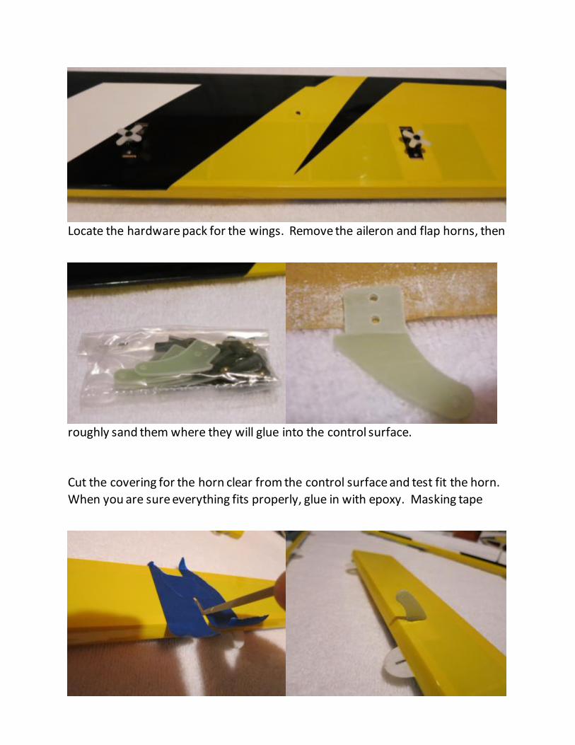
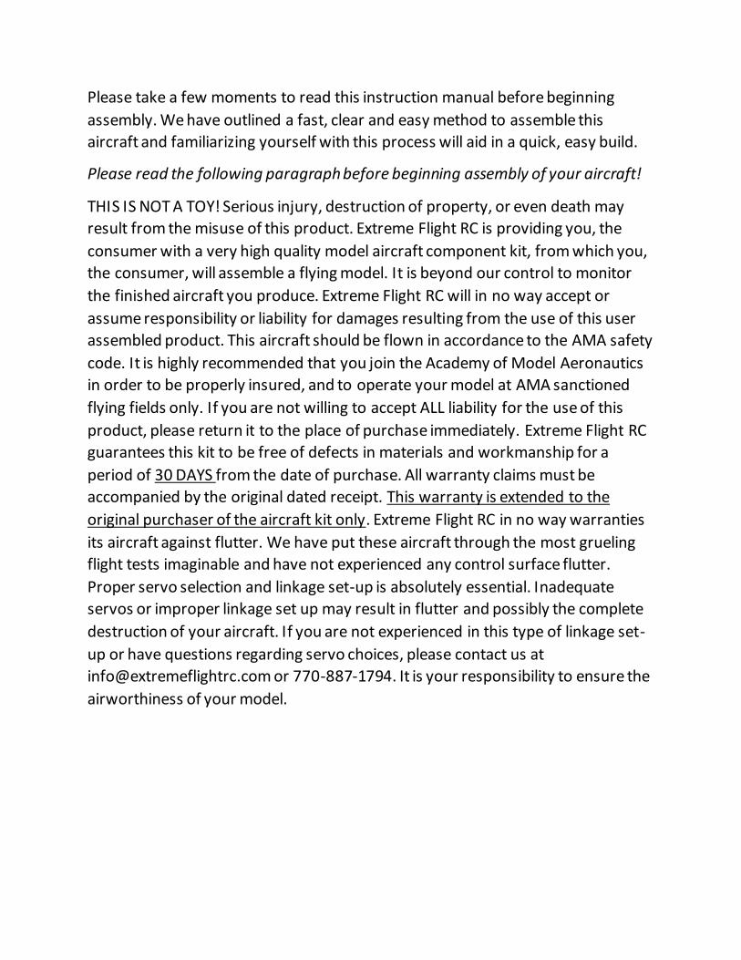
Locate the hardware pack for the wings. Remove the aileron and flap horns, then
roughly sand them where they will glue into the control surface.
Cut the covering for the horn clear from the control surface and test fit the horn.
When you are sure everything fits properly, glue in with epoxy. Masking tape

around the control horn slot will reduce a lot of mess from excess glue.
With all horns bonded into their respective control surfaces, the hinges can be
glued into the wings. One side of the CA hinge is already bonded into the control
surface. Insert the surface into the wing, move the surface through its full range
of motion to make sure the gap is not too tight, then put a drop of thin CA on
each side of the hinge, and let cure completely.
Next, assemble the pushrods and ball link ends, and assemble the control linkage
as shown.
Repeat this process for all ailerons and flaps.
Next, locate the holes for the inboard and outboard wing fences, and cut the

covering off of them. Install the fences, and glue in place with thin
CA.

Fuselage assembly Retrieve the fuselage, horizontal stabilizer, and
elevator.
Add a little bit of thin CA to every high stress area of the motor box and landing
gear plate.

Next, locate the hole for the stab in the fuselage, and the covering away from it.
Again, a hot knife and some patience makes for a clean result.
Insert the stab into the fuselage, ensuring that it is right side up.
Next, precisely line the stabilizer up in the fuselage. It must be perfectly centered
horizontally, and precisely square with the fuselage. This is achieved by
measuring the distance from the outer edge of the stab to the fuselage. After this
measurement is achieved, T-pins can be used to keep the stab centered. Tying a
piece of string to the hatch latch can help with achieving perfect alignment as
well. When the stab is positioned correctly, glue in place with thin CA.
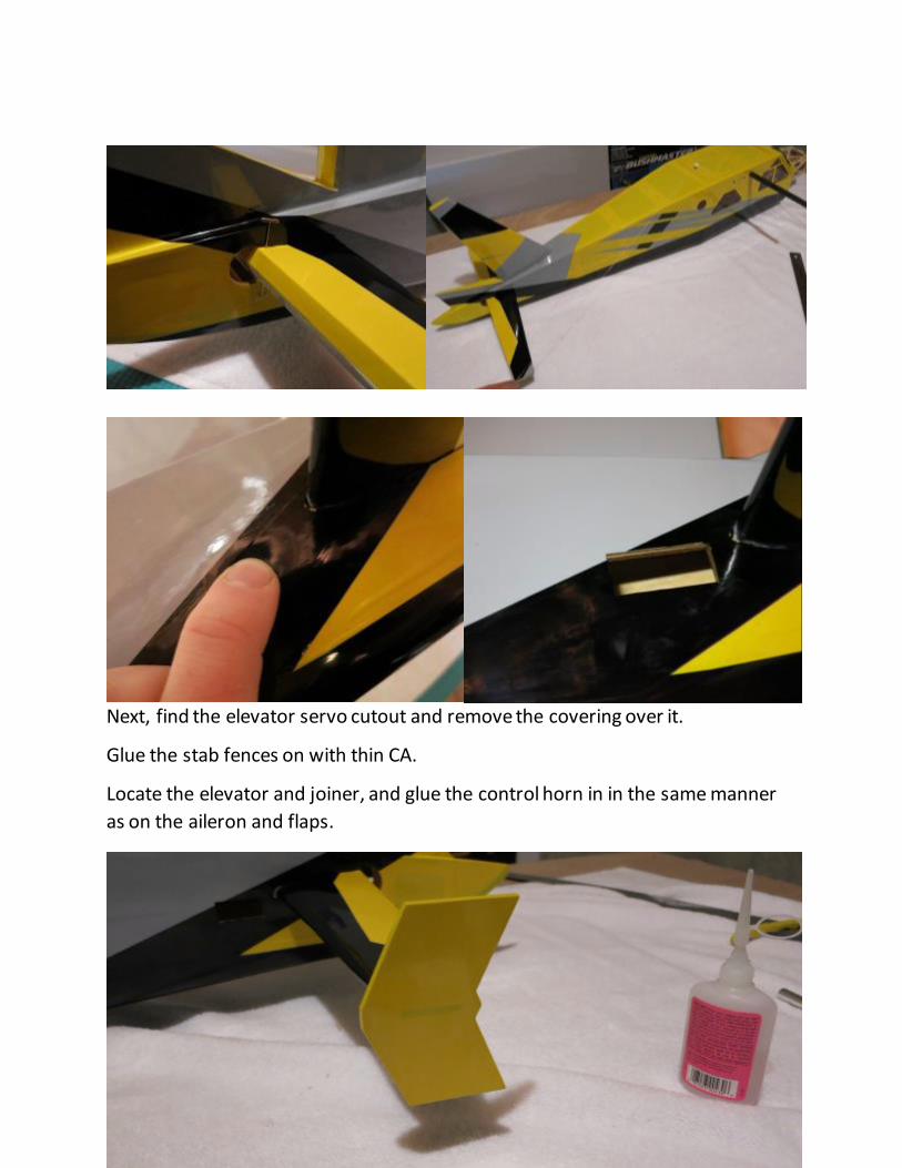
Next, find the elevator servo cutout and remove the covering over it.
Glue the stab fences on with thin CA.
Locate the elevator and joiner, and glue the control horn in in the same manner
as on the aileron and flaps.
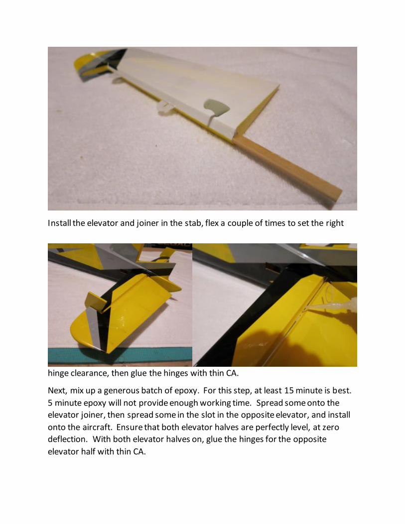
Install the elevator and joiner in the stab, flex a couple of times to set the right
hinge clearance, then glue the hinges with thin CA.
Next, mix up a generous batch of epoxy. For this step, at least 15 minute is best.
5 minute epoxy will not provide enough working time. Spread some onto the
elevator joiner, then spread some in the slot in the opposite elevator, and install
onto the aircraft. Ensure that both elevator halves are perfectly level, at zero
deflection. With both elevator halves on, glue the hinges for the opposite
elevator half with thin CA.

With the elevator halves installed, locate the rudder, remove the covering from
the rudder horn slot, then test fit the rudder horn in the rudder. With it perfectly
centered, glue in place with thin CA.
Install the rudder onto the fuselage, flex several times to ensure proper hinge
clearance, then glue the hinges with thin CA.

Elevator linkage installation Next, locate the elevator servo. Install the extension secure with heatshrink, then
install in the fuselage in the same manner as on the flaps and ailerons (using thin
CA to harden the screw holes). Note that the output shaft should face the front
of the plane. Install the elevator linkage as shown.

Landing gear Next, retrieve the land gear from your kit. First install the axles into the landing
gear legs, then secure the wheels to the axles with the clips as shown.
Bolt the landing gear to the fuselage bottom, using thread locking compound and
M3 bolts and washers. After the landing gear is bolted, install the landing gear
cover by gluing on with a removable adhesive such as silicone.

Install the tailwheel into the bottom of the fuselage. Be sure to loosen all set
screws, add thread locking compound, and reassemble.
With the airplane able to rest on its feet, it’s now a good time to install the keel in
the bottom of the fuselage. First locate the hole for it, then remove the covering.
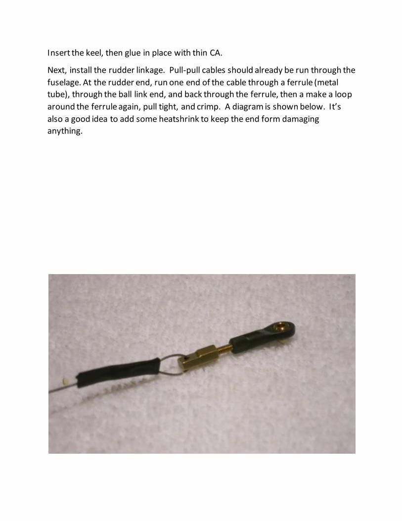
Insert the keel, then glue in place with thin CA.
Next, install the rudder linkage. Pull-pull cables should already be run through the
fuselage. At the rudder end, run one end of the cable through a ferrule (metal
tube), through the ball link end, and back through the ferrule, then a make a loop
around the ferrule again, pull tight, and crimp. A diagram is shown below. It’s
also a good idea to add some heatshrink to keep the end form damaging
anything.
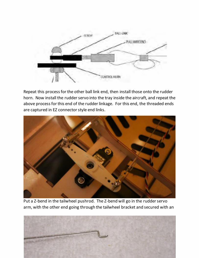
Repeat this process for the other ball link end, then install those onto the rudder
horn. Now install the rudder servo into the tray inside the aircraft, and repeat the
above process for this end of the rudder linkage. For this end, the threaded ends
are captured in EZ connector style end links.
Put a Z-bend in the tailwheel pushrod. The Z-bend will go in the rudder servo
arm, with the other end going through the tailwheel bracket and secured with an
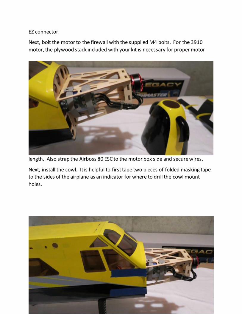
EZ connector.
Next, bolt the motor to the firewall with the supplied M4 bolts. For the 3910
motor, the plywood stack included with your kit is necessary for proper motor
length. Also strap the Airboss 80 ESC to the motor box side and secure wires.
Next, install the cowl. It is helpful to first tape two pieces of folded masking tape
to the sides of the airplane as an indicator for where to drill the cowl mount
holes.

Slip the cowl on, then install the spinner backplate onto the motor shaft. Use this
as a guide for positioning the cowl with a minimal spinner gap.
Use the tape guides to accurately drill holes through the cowl, then screw the
cowl to the fuselage.
This concludes the assembly process for the Turbo Bushmaster. Preparing for flight! With the wing and struts attached, place your battery on the battery tray and pick up the Bushmaster by the wing tube. Shift the battery until the plane balances on the tube. This is a safe location to begin test flying. Adjust CG to your liking, then mark the tray to know where to position the battery each flight. Typically, the plane balances with the battery centered on the tray just forward of the wing tube. It is recommended you first fly the model in standard configuration to get used to its flight characteristics before beginning to experiment with flaps. When deploying flaps you will need to add an elevator mix that compensates for the flaps and provides a few degrees of down elevator. Thanks so much for your business and we hope you enjoy flying your Turbo Bushmaster as much as we have!


