BN653030EX-0818 R00 Impreso en México CAT II EQUIPMENT EQUIPO CAT II MODELS 653030, 653035 653060 This equipment is ideal for cutting grass and/or weeds, for roadside and pasture maintenance, and for shredding crop leftovers. Este equipo es ideal para labores de limpieza en terrenos y caminos, cortar pastos y/o maleza y para desmenuzar los residuos de cosechas. OPERATOR'S MANUAL MANUAL DE OPERADOR ROTARY CUTTER CORTADORA ROTATIVA
Transcript
BN653030EX-0818R00
Impreso en México
CAT II EQUIPMENTEQUIPO CAT II
MODELS
653030, 653035653060
This equipment is ideal for cutting grass and/or weeds, for roadside and pasture maintenance, and for shredding crop leftovers.
Este equipo es ideal para labores de limpieza en terrenos y caminos, cortar pastos y/o maleza y para desmenuzar los residuos de cosechas.
OPERATOR'S MANUALMANUAL DE OPERADOR
ROTARY CUTTERCORTADORA ROTATIVA
1
INDEX
INTRODUCTION1.This product was carefully designed and manufactured for optimal performance, economy, and ease of use. It is important for any operator of this product to go over all information contained in this manual, to follow these step-by-step instructions, and to have the manual on hand for reference when needed.
This manual contains important safety information: Read this information carefully and be on the lookout for any possible accidents. Keep all labeling on the equipment and replace labeling if necessary.
This equipment enables you to clear land of quick-growing vegetation, small shrubs, and grass; it can also be used to shred the leftovers of crops such as corn, wheat, barley, sorghum, etc.
SAFETY INFORMATION2. In this section, we will discuss the most important points for ensuring your safety and the safety of others.
2.1 PROTECTIVE EQUIPMENT
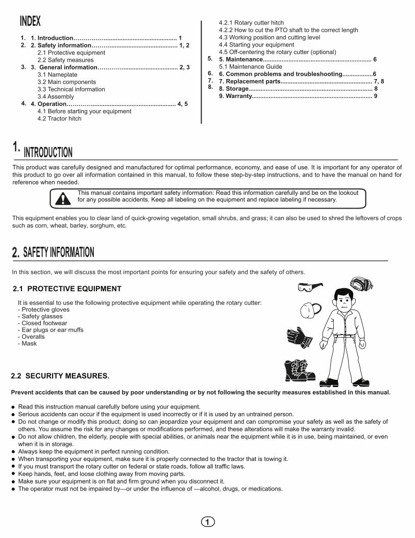
It is essential to use the following protective equipment while operating the rotary cutter:- Protective gloves- Safety glasses- Closed footwear- Ear plugs or ear muffs- Overalls- Mask
4.
6.
5.
7.8.
4.2.1 Rotary cutter hitch4.2.2 How to cut the PTO shaft to the correct length4.3 Working position and cutting level4.4 Starting your equipment4.5 Off-centering the rotary cutter (optional)5. Maintenance................................................................ 65.1 Maintenance Guide6. Common problems and troubleshooting..................67. Replacement parts...................................................... 7, 88. Storage......................................................................... 89. Warranty....................................................................... 9
1.2.
3.
1. Introduction……………........................................... 12. Safety information………........................................ 1, 2 2.1 Protective equipment 2.2 Safety measures3. General information…………................................. 2, 3 3.1 Nameplate 3.2 Main components 3.3 Technical information 3.4 Assembly4. Operation………….................................................. 4, 5 4.1 Before starting your equipment 4.2 Tractor hitch
2.2 SECURITY MEASURES.
Read this instruction manual carefully before using your equipment.Serious accidents can occur if the equipment is used incorrectly or if it is used by an untrained person.Do not change or modify this product; doing so can jeopardize your equipment and can compromise your safety as well as the safety of others. You assume the risk for any changes or modifications performed, and these alterations will make the warranty invalid.Do not allow children, the elderly, people with special abilities, or animals near the equipment while it is in use, being maintained, or even when it is in storage.Always keep the equipment in perfect running condition.When transporting your equipment, make sure it is properly connected to the tractor that is towing it.If you must transport the rotary cutter on federal or state roads, follow all traffic laws.Keep hands, feet, and loose clothing away from moving parts.Make sure your equipment is on flat and firm ground when you disconnect it.The operator must not be impaired by—or under the influence of —alcohol, drugs, or medications.
Prevent accidents that can be caused by poor understanding or by not following the security measures established in this manual.
Follow all instructions on the product’s labels.
GENERAL INFORMATION.3.In this section, we will discuss the product’s components.
3.1 NAMEPLATE
Calle Swissmex No. 500 Col. Las Ceibas47440 Lagos de Moreno Jalisco
MODELSERIES No.
Your equipment has a nameplate that includes the model and serial number. This information is necessary to file warranty claims and to obtain replacement parts. Record your equipment’s information so you always have this information at hand.
Make sure the equipment you have received is complete and includes the following items:
- Complete housing with shield - Transmission and PTO - Blade carrier and blades
TECHNICAL INFORMATION3 3.
Tractor hitchModel
Cutting widthPTO RPMGearbox
Cardan shaft
Frontal protectionBlades
Cutting height
Working speedWheel Reinforced solid rubber
Minimum horsepower requiredBlade RPM
Weight
Three-point653030 653035 653060
1.5 m = 4.9 feet 1.8 m = 5.9 feet540 RPM
60 HP, 1:1.5 ratio
Metal shields4 double-edged steel blades, reversible and free-spinning
AdjustableReinforced solid rubber4 to 10 km/h (2 to 6 mph)
60 HP1004 (540 RPM of tractor PTO) 1004 (540 RPM of tractor
PTO) 300 kg. 330 kg.
Equipped with clutch springs: model 653060 and 653035 also include a freewheel.
ESPECIFICATIONS
3
1. HOUSING: made of thick sheet metal appropriate for heavy use.
3. WHEEL HOLDER: with set screws to adjust height.
5. BLADE CARRIER: keeps the equipment stable and holds the folded blades.
6. BLADES: double-edged, reversible, freely rotating, made of long-lasting steel.
8. PTO: its purpose is to transmit motor force from the tractor engine to the rotary cutter.
7. PROTECTIVE SHIELDS: made of thick sheet metal, these prevent material from shooting out of the equipment at high speeds, protecting the operator and the surroundings.
3. WHEEL HOLDER: with set screws to adjust height.
2. TRANSMISSION: reinforced 60 HP with automotive bevel gears that rotate on high-resistance bearings.
This rotary cutter is designed to operate with a tractor equipped to 540 rpm PTO drive. Never connect your rotary cutter to a 1000 rpm PTO tractor; this can damage the equipment and poses a great risk to the tractor and the operator.When installing the PTO driveline between the tractor and the rotary cutter, you should be aware of the oscillation of the driveline’s telesco-ping members. Make sure that they are not too short—in which case they may become disconnected—nor too long, in which case they may push on the tractor’s PTO or main transmission box and damage it; for this reason, you must inspect the driveline telescoping before operating your equipment. If too long, the ends of the tubes can be trimmed; if too short, a longer PTO driveline is required.
1. Attach the rotary cutter by securing it to the tractor hitch. 2.- Install the driveline shaft and make sure it fits correctly (with at least 1/3 of the tubes overlapping). If it is too short or too long, adjust the driveline shaft that connects to the tractor by cutting the male and female shafts so that the correct overlap remains after the rotary cutter is connected (see the instruc tions for cutting the driveline shaft below).
1/3 overlap
MINIMUM
2/3 Ideal overlap
WORK LEIGHT APROX. 2/3 Lu
NOTE: Verify which side goes to the tractor and which side goes to the rotary cutter (on the PTO label).
4.2.3 CUTTING THE DRIVELINE SHAFT TO THE CORRECT SIZE
- Separate the driveline shaft into two parts.- Mount half the shaft onto the tractor and half the shaft onto the implement.- Align the implement so that the two half shafts are at the same height.- Place one half driveline shaft next to the other half driveline shaft.- Measure 40mm from the start of the plastic shielding tube- Cut the plastic shielding (cut the same length for both half shafts).- Cut the male and female shafts the same length that the protective shielding was cut.- Round off the cutting edges and clean up the filings carefully.- Grease the PTO driveline shaft and the plastic shielding.
40 M M
NOTE: Keep in mind that the female shaft always goes to the tractor and the male shaft goes to the implement.
NOTE: For your own safety, make sure the PTO and the driveline shaft are fully connected and that the lock is in place, so they do not come loose while you are working.
OPERATION4.
Make sure that all parts are in place and all screws and nuts tightened.Adjust the height of the equipment and the cut level.Before you begin your work, familiarize yourself with the parts of the rotary cutter and its safety indications.Exercise extreme caution when using your rotary cutter.Make sure that the rotary cutter is on level ground prior to use.Keep hands and feet away from moving parts. Keep hands and feet away from moving parts.
Your equipment has a category 2 three-point hitch, which can be connected to any tractor with a universal three-point hitch. When attaching, you must watch the alignment between the tractor and the rotary cutter, adjusting the width between one tractor arm and the other, if necessary, by adjusting the tractor’s stabili-zer arms.
4.1 BEFORE STARTING YOUR EQUIPMENT
TRACTOR HITCH4.2
4.2.1 ROTARY CUTTER HITCH
4
Step 1:
Adjust the height of the rotary cutter, making sure that the side skids do not touch the ground on either side. The skids should be slightly above ground level, and you should make sure that the blades will not strike furrows when going over furrowed land.
Step 2:
Adjust the height of the rotary cutter: Adjust the rotary cutter height using the wheel holder. Slide the shaft tube for the desired height and secure it with the wheel holder brackets, using the screws to make adjustments.
To maximize the life of your rotary cutter and its blades, you must avoid striking the soil while working. Your equipment has various features for proper levelling. After placing the tractor and rotary cutter on level ground, complete the following steps:
WORKING POSITION AND ADJUSTING THE CUT LEVEL4.3
3 point attachment
Shield
Wheel holder
Wheel holderclamp
Using the rotary cutter is simple and easy. The rotary cutter operates on the power transmitted by the tractor PTO. To begin operating the rotary cutter, follow these steps:
a) Your equipment has a front skirt designed to prevent any stones or pieces of brush from shooting from the blades and injuring the driver.b) Start the tractor and PTO at a low rpm, then operate your tractor engine between 1800 to 2000 rpm; this will guarantee a 540 rpm for the PTO shaft.c) Move to the working area and make sure that the skids are just above the ground. In this position, the blades will have free range of motion and will not strike the soil.d) If you want a higher cutting level, adjust the cutting height by adjusting the height of the rotary cutter with the tractor hydraulic system. If necessary, turn off the equipment and adjust the wheel holder.e) Once the cutting height has been selected, adjust the operating lever of your tractor's hydraulic system so that your equipment lowers to the same level and the cutting level will be uniform. For safety, we recommend raising your rotary cutter about 30 cm at the edges of the working area, so you can turn the tractor around and lower the rotary cutter to the selected level before starting a new cut.
STARTING YOUR EQUIPMENT:4.4
This rotary cutter has two operating positions. One is the central tractor position; the other is the off-center position. Changing between the two positions is very easy and can be done by following these steps:
a) Remove the screws from the transmission box and turn it about 25°, according to the transmission and housing perforations, and tighten the screws again. b) Remove the screws from the 3rd point coupling straps and the housing support straps.c) Move the hitch for 1st and 2nd points to the new strap supports or housing supports.d) Next, place the third point hitch in the new position and tighten the screws.e) Finally, place the third point and the coupling strap in the new position and tighten the screws.
DECENTERING THE ROTARY CUTTER (OPTIONAL):4.5
a)
b) c) d) e)
5
This product is easy to maintain. If you follow the steps in this manual, your product will have a very long service life.
5.1 DAILY MAINTENANCE GUIDE:
MAINTENANCE5.
: We have repair and maintenance services for SWISSMEX products. Only repair your own equipment if you know how to do so. Otherwise, consult a professional.
To ensure optimal performance, use only SWISSMEX-RAPID replacement parts.
NOTE:
NOTE:
COMMON PROBLEMS AND TROUBLESHOOTING6.PROBLEM CAUSE SOLUTION
Incorrect cutting
Uneven cutting
Cut material accumulates in the housing.
Blades not rotating
Excessive vibration
1.- Sharpen the blades.2.- Reduce working speed.3.- Bring the PTO to 540 RPM.
11.- Lift the housing.2.- Work carefully, avoiding all obstacles.
1.- Calibrate the clutch.2.- Replace.
1.- Sharpen the blades uniformly or replace with new ones.2.- Tighten screws.
1.- Dull blade.2.- Excessive speed.3.- Low RPM.
1.- Cutting height too low2.- Working in areas with obstacles or stones.
1.- Clutch is slipping.2.- Broken shear bolt.
1.- Worn or broken blades.
2.- Loose screws.
1. Incorrect third point length.2. Rear wheel not levelled correctly.
1. Correct the third point length.2. Correct the position of the rear wheel’s support bar.
NOTE: Be aware that using rotary cutters with dull blades will reduce performance, cause your equipment to vibrate excessively, and may cause damage to your equipment.
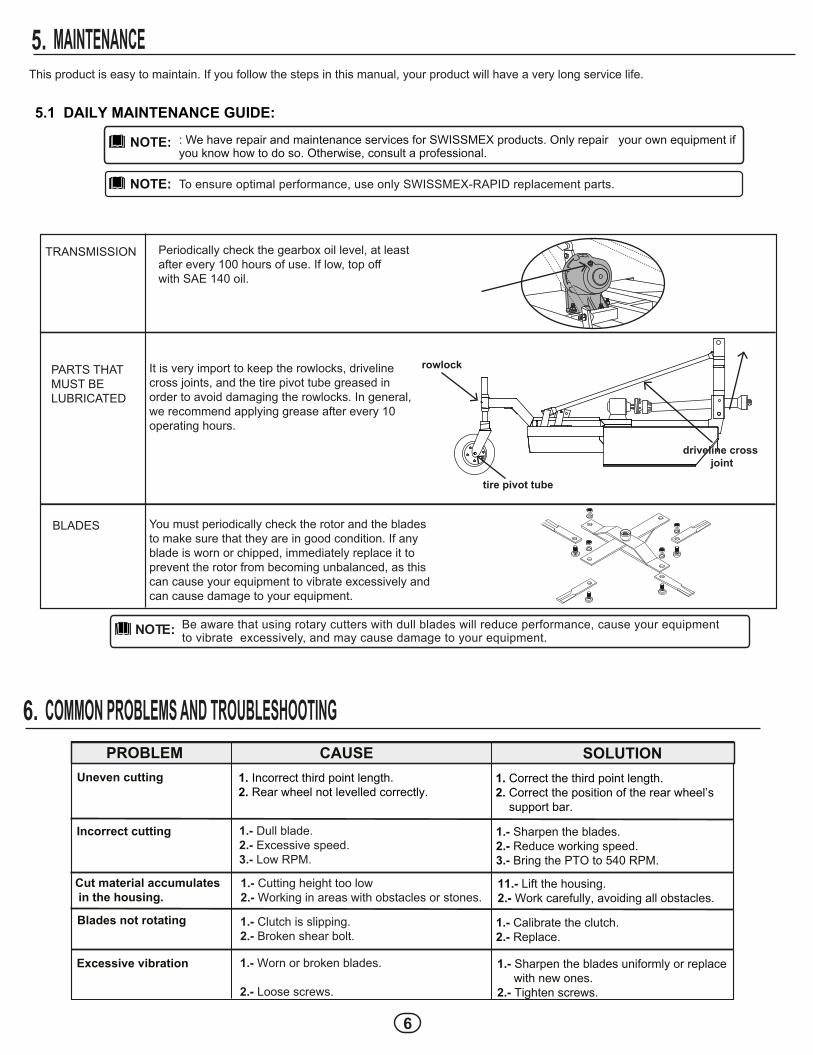
TRANSMISSION Periodically check the gearbox oil level, at least after every 100 hours of use. If low, top off with SAE 140 oil.
PARTS THAT MUST BE LUBRICATED
It is very import to keep the rowlocks, driveline cross joints, and the tire pivot tube greased in order to avoid damaging the rowlocks. In general, we recommend applying grease after every 10 operating hours.
BLADES You must periodically check the rotor and the blades to make sure that they are in good condition. If any blade is worn or chipped, immediately replace it to prevent the rotor from becoming unbalanced, as this can cause your equipment to vibrate excessively and can cause damage to your equipment.
driveline cross joint
tire pivot tube
rowlock
6
Because of our focus on technological advancement, we reserve the right to make changes or technical modifications to these products without prior notice.
NOTE:BLADE CARRIER SCREW1/8" "R" PINPTO (model 653035)60 HP GEARBOXBLADE CARRIERBLADE CARRIERWHEEL HOLDERTIRE WITH AXLEBRACKET FOR WHEEL HOLDERTHREE-POINT HITCH PIN¼” THREADED STRAIGHT GREASE FITTING
STORAGE:8.Always store your equipment in a covered area to avoid damage by sun and rain.
Because of our focus on technological advancement, we reserve the right to make changes or technicalmodifications to these products without prior notice.
NOTE:
BLADE CARRIER SCREW1/8" "R" PIN60 HP GEARBOXWHEEL HOLDERTIRE WITH AXLEBRACKET FOR WHEEL HOLDER¼” THREADED STRAIGHT GREASE FITTING PTO
To validate your warranty, you must adhere to the Warranty Policy described below:
SWISSMEX RAPID SA DE CV will honor the warranty free of charge when any parts or components are found to have manu-facturing or assembly defects after conclusive analysis at the manufacturing plant (Lagos de Moreno, Jalisco). Once the damages have been verified and evaluated, the warranty will cover replacement parts or equipment for the damaged parts or equipment. The warranty does not cover labor or transportation.Your product warranty may be PREMIUM, MEDIUM, or BASIC, depending on the category of your equipment. The category is specified on the cover of the product manual. You may also verify the product category on the website or by using a product catalog.
The warranty does not apply when: • The cause of damage cannot be attributed to manufacturing defects or defective materials. • Improper use of the equipment, or usage for which the equipment was not designed, and which is not recommended by the user manual and its standards. • Damage caused by natural disasters (earthquakes, floods, fires, lightning, and storms). • When the equipment has suffered accidental or intentional blows, or when it has been exposed to harmful elements, includ ing water, fire, inclement weather, etc. • The customer assumes responsibility for damages that occur during transportation. • If the serial number has been defaced or removed. • If you use parts other than original Swissmex parts, in the case of commercialized products. • Improper maintenance or maintenance performed by individuals who have not been authorized by Swissmex. • If the original product design has been modified or altered. • In cases of misuse, negligence, accidents, or when the rotary cutter is connected to a tractor with a power rating different from what is specified on the technical sheet. • Incomplete warranty form.The Swissmex company covers damages sustained during transport for OCIMA-certified equipment.
Swissmex is not responsible for accidents or fatal injuries related to the equipment, nor is it responsible for theft.
The warranty does not cover: • Consumables and normal wear and tear. • Electrical parts. • General replacement parts. • The costs and fees related to shipping, transportation, and delivery services.
Product warranties must be handled by the product vendor or by the end user via e-mail: [email protected] products imported and marketed by Swissmex Rapid SA DE CV, the warranty period is established by the equipment manufacturer. Check your product manual to determine the warranty period for your product.
THE CUSTOMER MUST FILL OUT THE PRODUCT WARRANTY FORM AT THE TIME OF SALE • Customer/user name: • Model: • Series number: • Date equipment was purchased: • Where it was purchased:
Customer’s seal and signature
IF THE PURCHASER DOES NOT COMPLETE THIS FORM THE PRODUCT WARRANTY IS NOT VALID.
ÍNDICE
INTRODUCCIÓN1.Gracias por comprar una desvaradora Swissmex, le garantizamos que el producto que ha adquirido cuenta con calidad insuperable ya que fue desarrollado con tecnología de punta, siguiendo los estándares de calidad requeridos.Este equipo fue cuidadosamente diseñado y fabricado con el fin de proporcionar el máximo rendimiento, economía y facilidad de operación. Es importante que el operador conozca toda la información contenida en este manual, léalo antes de operarlo, siga las recomendaciones paso a paso y téngalo a la mano para consultarlo cuando sea necesario.
Este manual contiene importantes advertencias de seguridad: lea con atención y esté atento a cualquier posible accidente. Conserve todas las etiquetas del equipo y si es necesario reemplácelas.
Con este equipo usted podrá realizar con facilidad limpieza de terrenos con vegetación espontánea, arbustos pequeños, pasto y triturar el resto de la cosecha anterior como pata de maíz, trigo, cebada, sorgo, etc.
INFORMACIÓN DE SEGURIDAD2.A continuación describiremos los puntos más importantes a revisar para la seguridad de usted y de terceros.
2.1 EQUIPO DE PROTECCIÓN
- Guantes protectores- Lentes de seguridad- Zapatos cerrados- Tapones auditivos o conchas- Ropa ceñida
4.
6.
5.
7.8.
4.2 Acople al tractor 4.2.1 Enganche de la desvaradora 4.2.2 Como cortar el eje cardán al largo correcto4.3 Posición de trabajo y nivelación de corte4.4 Puesta en marcha4.5 Descentrado de la desvaradora (opcional)Mantenimiento.............................................................. 6, 75.1 Guía para mantenimientoPosibles problemas, causas y soluciones................. 7Refacciones................................................................... 8, 9Almacenamiento...........................................................10
1.2.
3.
Introducción……………....................1Información de seguridad………...... 1, 22.1 Equipo de protección2.2 Medidas de seguridadInformación general…………............ 3, 43.1 Placa de identificación3.2 Componentes principales3.3 Datos técnicos3.4 EnsambleOperación………….................................................. 4, 5, 64.1 Que debe hacer antes de poner en marcha su equipo
10
2.2 MEDIDAS DE SEGURIDAD
Antes de poner su equipo en funcionamiento lea cuidadosamente este manual de instrucciones.La manipulación incorrecta y por personas no capacitadas puede ocasionar accidentes graves.No haga adaptaciones o improvisaciones; estas comprometen su equipo y ponen en riesgo su seguridad y la de terceros. Todas las modificaciones o adaptaciones que haga serán bajo su propio riesgo y esto hace inválida la garantía.No permita la presencia de niños, ancianos, personas con capacidades especiales o animales próximos al equipo durante su uso, mantenimiento, e incluso durante su almacenaje.Mantenga el equipo siempre en perfecto estado de conservación.Al transportar su equipo, verifique que el acople al tractor que lo remolcará sea correcto .Si por necesidades de su trabajo con la desvaradora requiere transitar por carreteras federales, estatales, siga las normas de vialidad.Mantenga las manos, los pies y ropa holgada lejos de piezas móviles.Al desconectar su equipo asegúrese de que se haga en terrenos planos y firmes.El operador, no deberá estar bajo los efectos del alcohol, drogas o medicamentos.
Siga las indicaciones de las etiquetas adheridas a su equipo.
Evite accidentes por falta de conocimiento y por no seguir la reglas de seguridad descritas en este manual.
INFORMACIÓN GENERAL3.En esta sección le mostraremos que compone su equipo.
3.1 PLACA DE IDENTIFICACIÓN
Calle Swissmex No. 500 Col. Las Ceibas47440 Lagos de Moreno Jalisco
MODELONo. DE SERIE
Su equipo cuenta con una placa de identificación donde se encuentra el modelo y número de serie, esta información será útil para en caso de tramitar una garantía o requerir refac-ciones. Anote los datos de su equipo para que tenga la información siempre a la mano.
11
653060
653030, 653035
3.2 COMPONENTES PRINCIPALES
1. Carcasa completa2. Transmisión3. Porta llanta4. Llanta 5. Porta cuchillas6. Cuchillas7. Cortinas8. Toma de fuerza
3
77
1
1
5
5
6
6
4
2
8
8
1. CARCASA: fabricada en lámina de grueso calibre, propia para uso pesado.
2. TRANSMISIÓN: reforzada de 60 HP, con engránes cónicos automotrices, que giran sobre rodamientos de alta resistencia.
3. PORTA LLANTA: con ajuste de altura mediante opresores.
4. LLANTA: fabricada de tacones de hule sólido muy reforzada para larga duración.
5. PORTA CUCHILLAS: mantiene estabilidad en el equipo y sostiene las cuchillas de forma abatible.
6. CUCHILLAS: de doble filo reversible con giro libre fabricadas de ácero de larga vida.
7. CORTINAS DE PROTECCIÓN: metálica de calibre grueso que evita que el material salga proyectado a gran velocidad protegiendo al operador y al entorno.
8. TOMA DE FUERZA: su función es transmitir la fuerza motriz de PTO del tractor a la desvaradora.
1
2
3
5
4
6
7
8
12
OPERACIÓN4.
ENSAMBLE3 4.
Verifique que su equipo esté completo y que reciba lo siguiente:
- Carcasa completa con cortina - Transmisión y toma de fuerza - Porta navajas y navajas
Revise visualmente que todas las partes equipo estén en su lugar como tornillos y tuercas bien ajustadas.Ajuste la posición de trabajo de su equipo y la nivelación de corte.Antes de iniciar su jornada de trabajo primeramente familiaricese con las partes de desvaradora y las señales de seguridad.Extreme precauciones cuando maneje su desvaradora.Compruebe que la desvaradora esté situada en una superficie nivelada antes de su uso.Mantenga las manos y los pies alejados de la piezas en movimiento.
Su equipo cuenta con enganche a tres puntos catergoría II, puede ser enganchado a cualquier tractor con enganche universal de tres puntos de levante, para ello se debe cuidar la alineación entre el tractor y la desvaradora, si es necesario se debe ajustar el ancho entre un brazo y otro del tractor ajustando los tensores de los brazos del tractor.
4.1 QUE DEBE HACER ANTES DE PONER EN MARCHA SU EQUIPO
ACOPLE AL TRACTOR4.2
4.2.1 ENGANCHE DE LA DESVARADORA
DATOS TÉCNICOS3 3.
Acople al tractorModelo
Ancho de corteVelocidad de la toma de fuerza
Caja de engranesEje cardán
Protección frontalNavajas
Altura de corteRueda
Velocidad de trabajoPotencia mínima requerida
RPM de las cuchillas
Peso
Tres puntos653030 653035 653060
1.5 m = 4.9 pies 1.8 m = 5.9 pies540 RPM
60 HP; relación 1-1.50
Cortinas metálicas4 en acero de doble filo, reversibles de giro libre
Ajustable a diversas posicionesRevestimiento de hule sólido (de tacones)
4 a 10 km/h60 HP
1004 (a 540 RPM de la tomade fuerza del tractor)
1004 (a 540 RPM de la tomade fuerza del tractor)
300 kg. 330 kg.
Equipado con clutch de resortes; el modelo 653060, 653035 incluye ademas una rueda libre.
ESPECIFICACIONES
13
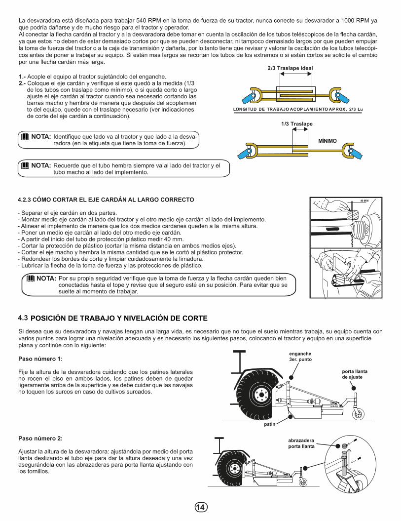
La desvaradora está diseñada para trabajar 540 RPM en la toma de fuerza de su tractor, nunca conecte su desvarador a 1000 RPM ya que podría dañarse y de mucho riesgo para el tractor y operador.Al conectar la flecha cardán al tractor y a la desvaradora debe tomar en cuenta la oscilación de los tubos teléscopicos de la flecha cardán, ya que estos no deben de estar demasiado cortos por que se pueden desconectar, ni tampoco demasiado largos por que pueden empujar la toma de fuerza del tractor o a la caja de transmisión y dañarla, por lo tanto tiene que revisar y valorar la oscilación de los tubos telecópi-cos antes de poner a trabajar su equipo. Si están mas largos se recortan los tubos de los extremos o si están cortos se solicite el cambio por una flecha cardán más larga.
1.- Acople el equipo al tractor sujetándolo del enganche. 2.- Coloque el eje cardán y verifique si este quedó a la medida (1/3 de los tubos con traslape como mínimo), o si queda corto o largo ajuste el eje cardán al tractor cuando sea necesario cortando las barras macho y hembra de manera que después del acoplamien to del equipo, quede con el traslape necesario (ver indicaciones de corte del eje cardán a continuación).
1/3 Traslape
MÍNIMO
2/3 Traslape ideal
LONGITUD DE TRABAJO ACOPLAM IENTO APROX. 2/3 Lu
NOTA: Identifique que lado va al tractor y que lado a la desva- radora (en la etiqueta que tiene la toma de fuerza).
4.2.3 CÓMO CORTAR EL EJE CARDÁN AL LARGO CORRECTO
- Separar el eje cardán en dos partes.- Montar medio eje cardán al lado del tractor y el otro medio eje cardán al lado del implemento.- Alinear el implemento de manera que los dos medios cardanes queden a la misma altura.- Poner un medio eje cardán al lado del otro medio eje cardán.- A partir del inicio del tubo de protección plástico medir 40 mm.- Cortar la protección de plástico (cortar la misma distancia en ambos medios ejes).- Cortar el eje macho y hembra la misma cantidad que se le cortó al plástico protector.- Redondear los bordes de corte y limpiar cuidadosamente la limadura.- Lubricar la flecha de la toma de fuerza y las protecciones de plástico.
Paso número 1:
Fije la altura de la desvaradora cuidando que los patines laterales no rocen el piso en ambos lados, los patines deben de quedar ligeramente arriba de la superficie y se debe cuidar que las navajas no toquen los surcos en caso de cultivos surcados.
Paso número 2:
Ajustar la altura de la desvaradora: ajustándola por medio del porta llanta deslizando el tubo eje para dar la altura deseada y una vez asegurándola con las abrazaderas para porta llanta ajustando con los tornillos.
40 M M
Si desea que su desvaradora y navajas tengan una larga vida, es necesario que no toque el suelo mientras trabaja, su equipo cuenta con varios puntos para lograr una nivelación adecuada y es necesario los siguientes pasos, colocando el tractor y equipo en una superficie plana y continúe con lo siguiente:
POSICIÓN DE TRABAJO Y NIVELACIÓN DE CORTE4.3
NOTA: Recuerde que el tubo hembra siempre va al lado del tractor y el tubo macho al lado del implemtento.
NOTA: Por su propia seguridad verifique que la toma de fuerza y la flecha cardán queden bien conectadas hasta el tope y revise que el seguro esté en su posición. Para evitar que se suelte al momento de trabajar.
enganche 3er. punto
patín
porta llantade ajuste
abrazadera porta llanta
14
El funcionamiento de la desvaradora es simple y sencillo, que trabaja por medio de la potencia que el tractor transmite por la toma de fuerza. Para ponerla en marcha siga estos pasos:
a) Su equipo cuenta con un faldón frontal para evitar que las navajas al trabajar lancen trozos de maleza o piedras al conductor. b) Con bajas revoluciones en su tractor, ponga el PTO, revolucionelo entre 1800 a 2000 rpm, en el tacómetro y con esto garantizará 540 RPM en el PTO del tractor.c) Cóloquese en el terreno de trabajo y cuide que los patines apenas hagan contacto con el piso. En esta posición las navajas trabajan libremente sin golpear en el piso.d) Si desea realizar cortes a mayor altura, levante ligeramente la desvaradora con el hidráulico del tractor, asi seleccione la altura de corte adecuado, si se requiere ajuste el porta llanta.e) Una vez seleccionada la altura de corte, ajuste el tope en la palanca del hidráulico de su tractor, asi siempre bajará su equipo a la mis- ma altura y el corte será uniforme, por seguridad se recomienda levantar la desvaradora unos 30 cm en las orillas del terreno para dar las vueltas al tractor y bajarla al nivel seleccionado para iniciar un nuevo corte.
PUESTA EN MARCHA4.4
La desvaradora tiene dos posiciónes de trabajo. Una es la posición central al tractor, y la otra es la posición descentrada del tractor. Para hacer el cambio es muy sencillo, proceda con lo siguiente:
a) Quite los tornillos de la caja de transmisión y gírela unos 25° que conicidan las perforaciónes de la transmisión y carcasa, fijando nueva- mente.b) Retire los tornillos de los tirantes del acoplamiento del 3er punto y las orejas soporte de la carcasa.c) Mueva el enganche para 1o y 2o pto a las nuevas orejas o soportes de la carcasa.d) Ahora coloque el acoplamiento del 3er punto en la nueva posición y atorníllelo.e) Enseguida vuelva a colocar el 3er punto y los tirantes en la nueva posición y atorníllelos.
DESCENTRADO DE LA DESVARADORA (OPCIONAL)4.5
Este equipo es de mantenimiento sencillo, si usted sigue los pasos que le mencionamos en este manual, la vida útil será muy prolongada.
5.1 GUÍA PARA MANTENIMIENTO.
MANTENIMIENTO5.
Contamos con servicio de reparación y mantenimiento para los equipos SWISSMEX. Únicamente repare su equipo si sabe como hacerlo, de lo contrario acuda a un profesional.
Para asegurar un mejor funcionamiento use solo refacciones originales “SWISSMEX-RAPID”.
NOTA:
NOTA:
a)
b) c) d) e)
15
POSIBLES PROBLEMAS, CAUSAS Y SOLUCIONES6.
PROBLEMA CAUSA SOLUCIÓN
Corte incorrecto.
Corte desnivelado.
El material cortado se acumula en la carcasa.
Las cuchillas no giran.
Vibración excesiva
1.- Afile las cuchillas.2.- Reduzca velocidad de trabajo.3.- Acelere la toma de fuerza a 540 RPM.
1.- Levante la carcasa.2.- Opere con cuidado evitando los obstáculos.
1.- Hacer la calibración correcta del clutch.2.- Reemplace por otro.
1.- Afile uniformememente y/o reemplace por nuevas.2.- Apriete tornillería.
Coloque en posición la barra soporte dela rueda trasera.
Corrija longitud del tercer punto.
1.- Cuchillas sin filo.2.- Velocidad excesiva.3.- Bajas RPM.
1.- Baja de altura de corte.2.- Operación en lugares con obstáculos y pedregosos.
1.- Se patina el clutch.2.- Tornillo fusible roto.
1.- Cuchillas desgastadas ó rotas.2.- Tornillería floja.
2.- Rueda trasera mal nivelada.1.-
2.-1.- Longitud del tercer punto incorrecta.
NOTA: Recuerde que usar la desvaradoras con navajas sin filo, reducirá el rendimiento y causará vibraciones excesivas dañando su equipo.
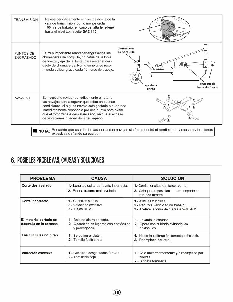
TRANSMISIÓN Revise periódicamente el nivel de aceite de la caja de transmisión, por lo menos cada 100 hrs de trabajo, en caso de faltarle rellene hasta el nivel con aceite SAE 140.
PUNTOS DE ENGRASADO
Es muy importante mantener engrasados las chumaceras de horquilla, crucetas de la toma de fuerza y eje de la llanta, para evitar el des-gaste de chumaceras. Por lo general se reco-mienda aplicar grasa cada 10 horas de trabajo.
NAVAJAS Es necesario revisar periódicamente el rotor y las navajas para asegurar que estén en buenas condiciones, si alguna navaja está gastada o quebradainmediatamente repóngala por una nueva para evitar que el rotor trabaje desvalanceado, ya que el exceso de vibraciones pueden dañar su equipo.
cruceta detoma de fuerza
eje de lallanta
chumacera de horquilla
16
Debido al interés en el progreso tecnológico, nos reservamos el derecho de hacer cambios o modificaciones técnicas sin previo aviso.
NOTA:TORNILLO PORTA CUCHILLASEGURO “R” 1/8”TOMA DE FUERZA (modelo 653035)CAJA DE ENGRANES 60 HPPORTA CUCHILLASPORTA CUCHILLASPORTA LLANTALLANTA DE TACÓN CON EJEABRAZADERA PARA PORTA LLANTAPERNO 3er. PUNTOGRACERA RECTA 1/4” CON ROSCA
A Piezas de desgaste y consumibles siempre disponibles.
MODELOS 653030, 653035
14
17
Debido al interés en el progreso tecnológico, nos reservamos el derecho de hacer cambios o modificaciones técnicas sin previo aviso.
NOTA:
TORNILLO PORTA CUCHILLASEGURO “R” 1/8”CAJA DE ENGRANES 60 HPPORTA LLANTALLANTA DE TACÓN CON EJEABRAZADERA PARA PORTA LLANTAGRACERA RECTA 1/4” CON ROSCATOMA DE FUERZA
A Piezas de desgaste y consumibles siempre disponibles.
MODELO653060
Piezas de uso medio, disponibles a discreción.
ALMACENAMIENTO8.Procure siempre dejar su equipo en un lugar techado para que el sol y la lluvia no lo deterioren.
18
GARANTÍA9.
Para hacer válida su garantía deberá apegarse a la Póliza de Garantía descrita a continuación:
La garantía será concedida por SWISSMEX RAPID SA DE CV, gratuitamente, cuando las piezas y los componentes presenten defectos de fabricación o de montaje y después de análisis conclusivo en planta (Lagos de Moreno, Jalisco). La garantía consiste en la sustitución de piezas dañadas por nuevas, o cambio del equipo dañado por uno nuevo, una vez que se haya verificado y evaluado el tipo de daño en el equipo, no incluye mano de obra o transporte.La garantía de su equipo puede ser PREMIUM, MEDIUM o BASIC, dependiendo de la categoría de su equipo, en la portada de su manual viene descrito de que categoría es, también puede consultarlo en la página web y en los catálogos de producto.
PLAZO DE LA GARANTÍALínea Premium = 12 mesesLínea Medium= 6 mesesLínea Basic = 3 meses
La garantía no procede cuando: • Causas no atribuibles a defectos de fabricación o vicios de material. • Mal uso del equipo o distinto del establecido en las normas y recomendaciones del manual de usuario y/o para lo que fue diseñado. • Daños ocasionados por desastres naturales (terremotos, inundaciones, incendios, tormentas eléctricas). • Cuando el producto haya recibido golpes accidentales o intencionales o haya sido expuesto a elementos nocivos como agua, ácidos, fuego, intemperie o cualquier otro similar. • Por daños sufridos durante el transporte, la mercancía viaja bajo riesgo del cliente. • Si se ha eliminado o borrado el número de serie. • Si usa refacciones NO originales Swissmex o del fabricante en el caso de los productos comercializados. • Mantenimiento incorrecto y/o personal no apto, realizado por personas no autorizadas por Swissmex. • Si sufrió modificaciones o alteraciones en el diseño original del producto. • Por abuso, negligencia, accidente o por utilizar un tractor de potencia diferente a la indicada en la ficha técnica. • Llenado incompleto de la garantía.En caso de ser un equipo certificado por el OCIMA la empresa Swissmex cubre los daños sufridos durante el transporte.
Swissmex no se hace responsable por accidentes, incidencias fatales ocasionadas por el equipo o robo.
La garantía no cubre: • Consumibles y piezas de desgaste natural.• Partes eléctricas.• Refacciones en general.• Los gastos de envíos, traslados o servicio de entrega y empaque.
Las garantías deberán ser tramitadas por el cliente que vendió el implemento o el usuario final a través del correo: [email protected].
En los productos importados y comercializados por Swissmex Rapid SA DE CV el plazo de garantía será el establecido por el fabricante del equipo. Revise en su manual que plazo equivale a su equipo.
OBLIGATORIO LLENAR POR EL CLIENTE AL MOMENTO DE LA VENTA
• Nombre cliente/usuario: • Modelo: • Nº de serie:• Fecha de adquisición del equipo:• Lugar donde lo adquirió:
Firma y sello del Cliente
SI EL CLIENTE NO LLENA ESTA INFORMACIÓN EL IMPLEMENTO NO TIENE GARANTÍA.


![EEx d, EEx de, EEX e, Ex nA, Ex N, EEx nA, DIP · ^eskimi i \lektrotehni^eskimi standartami, a takve soglasno sledu@]im ewropejskim normam: ... 1 Klass 2 ili EEx d, EEx de ,EEx e](https://static.documents.pub/doc/80x56/5ac92e3a7f8b9a40728d5c17/eex-d-eex-de-eex-e-ex-na-ex-n-eex-na-dip-eskimi-i-lektrotehnieskimi-standartami.jpg)


