20
EEX Line EEX Line (+50°C) EEX Line / IEC Ex EEX Line / U.S. (NEC 500/505) CSA Spring-applied single-disc brake
EEX LineEEX Line (+50°C)EEX Line / IEC Ex
EEX Line / U.S. (NEC 500/505) CSASpring-applied single-disc brake
2
EEX Line
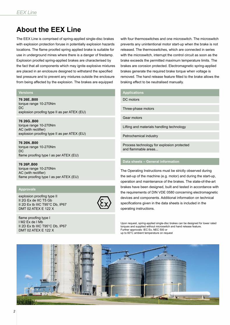
About the EEX LineThe EEX Line is comprised of spring-applied single-disc brakes with explosion protection foruse in potentially explosion hazards locations. The flame proofed spring applied brake is suitable for use in underground mines where there is a danger of firedamp. Explosion proofed spring-applied brakes are characterised by the fact that all components which may ignite explosive mixtures are placed in an enclosure designed to withstand the specified test pressure and to prevent any mixtures outside the enclosure from being affected by the explosion. The brakes are equipped
with four thermoswitches and one microswitch. The microswitch prevents any unintentional motor start-up when the brake is not released. The thermoswitches, which are connected in series with the microswitch, interrupt the control circuit as soon as the brake exceeds the permitted maximum temperature limits. The brakes are corosion protected. Electromagnetic spring-applied brakes generate the required brake torque when voltage is removed. The hand release feature fitted to the brake allows the braking effect to be neutralised manually.
The Operating Instructions must be strictly observed during the set-up of the machine (e.g. motor) and during the start-up, operation and maintenance of the brakes. The state-of-the-art brakes have been designed, built and tested in accordance with the requirements of DIN VDE 0580 concerning electromagnetic devices and components. Additional information on technical specifications given in the data sheets is included in the operating instructions.
Data sheets – General information
Versions
76 26E..B00 torque range 10-270NmDCexplosion proofing type II as per ATEX (EU)
76 26G..B00 torque range 10-270NmAC (with rectifier)explosion proofing type II as per ATEX (EU)
76 26N..B00 torque range 10-270NmDCflame proofing type I as per ATEX (EU)
76 26P..B00torque range 10-270NmAC (with rectifier)flame proofing type I as per ATEX (EU)
Applications
DC motors
Three-phase motors
Gear motors
Lifting and materials handling technology
Petrochemical industry
Process technology for explosion protected and flammable areas...
Approvals
explosion proofing type IIII 2G Ex de IIC T5 GbII 2D Ex tb IIIC T95°C Db, IP67DMT 02 ATEX E 122 X
flame proofing type II M2 Ex de I MbII 2D Ex tb IIIC T95°C Db, IP67DMT 02 ATEX E 122 X
Upon request, spring-applied single-disc brakes can be designed for lower rated torques and supplied without microswitch and hand release feature.Further approvals: IEC Ex, NEC 500 or up to 60°C ambient temperature on request
3
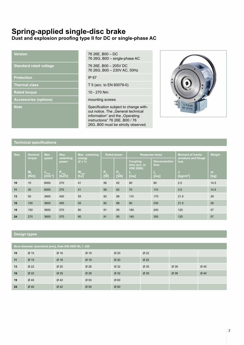
Version 76 26E..B00 – DC76 26G..B00 – single-phase AC
Standard rated voltage 76 26E..B00 – 205V DC76 26G..B00 – 230V AC, 50Hz
Protection IP 67
Thermal class T 5 (acc. to EN 60079-0)
Rated torque 10 - 270 Nm
Accessories (options) mounting screws
Note Specification subject to change with-out notice. The „General technical information“ and the „Operating instructions“ 76 26E..B00 / 7626G..B00 must be strictly observed.
Spring-applied single-disc brakeDust and explosion proofing type II for DC or single-phase AC
Bore diameter (standard) [mm], flute DIN 6885 BL.1 JS9
10 Ø 15 Ø 16 Ø 19 Ø 20 Ø 22
11 Ø 15 Ø 16 Ø 19 Ø 20 Ø 22
13 Ø 22 Ø 25 Ø 28 Ø 32 Ø 35 Ø 38 Ø 40
16 Ø 22 Ø 25 Ø 28 Ø 32 Ø 35 Ø 38 Ø 40
19 Ø 40 Ø 42 Ø 50 Ø 60
24 Ø 40 Ø 42 Ø 50 Ø 60
Design types
Technical specifications
Size Nominal torque
M2 [Nm]
Max. speed
nmax[min-1]
Max. switching power
Pmax[kJ/h]
Max. switching energy (Z = 1)
Wmax[kJ]
Rated power Response times Moment of inertia armature and flange hub
J[kgcm2]
Weight
m[kg]
PN[W]
PS[VA]
Couplingtime (acc. to VDE 0580)t1[ms]
Disconnection time
t2[ms]
10 10 6000 270 41 56 62 80 80 2.5 14.5
11 20 6000 270 41 56 62 70 110 2.5 14.5
13 50 3600 400 55 82 88 110 170 21.5 29
16 100 3600 400 55 82 88 90 230 21.5 29
19 150 3600 570 80 91 95 180 240 125 57
24 270 3600 570 80 91 95 140 350 125 57
4
EEX Line
Size d d1 d2 d3 (G7) d4 d5 b b1 b2 b3 b4 b5 b6 b7 b8 b9 b10 b11
10 178 130 1103) 121) / 222) 6.6 160 108 1 2.5 15 60.7 20 38 90 85 15 ca. 43 202
11 178 130 1103) 121) / 222) 6.6 160 108 1 2.5 15 60.7 20 38 90 85 15 ca. 43 202
13 245 180 1603) 201) / 452) 8.4 225 132 1 14 20 77.2 20 38 90 85 15 ca. 43 262
16 245 180 1603) 241) / 452) 8.4 225 132 1 14 20 77.2 20 38 90 85 15 ca. 43 262
19 330 260 2403) 301) / 702) 10.5 305 143 1 16 20 79.8 25 38 90 85 15 ca. 43 344
24 330 260 2403) 341) / 702) 10.5 305 143 1 16 20 79.8 25 38 90 85 15 ca. 43 344
Size h h1 L L1 s smax M M1 F [N] α ß
10 134 133 70 52 0.25+0.12 0.7 6xM6 2xM6 ca. 18 ca. 19° 10°
11 134 133 70 52 0.25+0.12 0.7 6xM6 2xM6 ca. 35 ca. 19° 10°
13 164 161 90 83 0.25+0.15 0.9 6xM8 3xM8 ca. 45 ca. 19° 68°
16 164 161 90 83 0.25+0.15 0.9 6xM8 3xM8 ca. 90 ca. 19° 68°
19 215 205 100 92 0.25+0.2 1.1 6xM10 3xM10 ca. 85 ca. 19° 70°
24 215 205 100 92 0.25+0.2 1.1 6xM10 3xM10 ca. 170 ca. 19° 70°
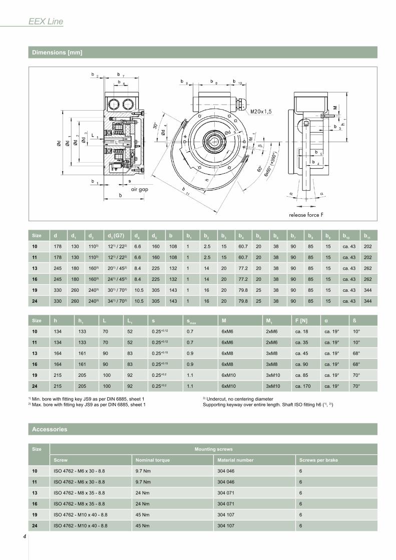
1) Min. bore with fitting key JS9 as per DIN 6885, sheet 12) Max. bore with fitting key JS9 as per DIN 6885, sheet 1
3) Undercut, no centering diameterSupporting keyway over entire length. Shaft ISO fitting h6 (1), 2))
Size Mounting screws
Screw Nominal torque Material number Screws per brake
10 ISO 4762 - M6 x 30 - 8.8 9.7 Nm 304 046 6
11 ISO 4762 - M6 x 30 - 8.8 9.7 Nm 304 046 6
13 ISO 4762 - M8 x 35 - 8.8 24 Nm 304 071 6
16 ISO 4762 - M8 x 35 - 8.8 24 Nm 304 071 6
19 ISO 4762 - M10 x 40 - 8.8 45 Nm 304 107 6
24 ISO 4762 - M10 x 40 - 8.8 45 Nm 304 107 6
Dimensions [mm]
Accessories
release force F
air gap
5
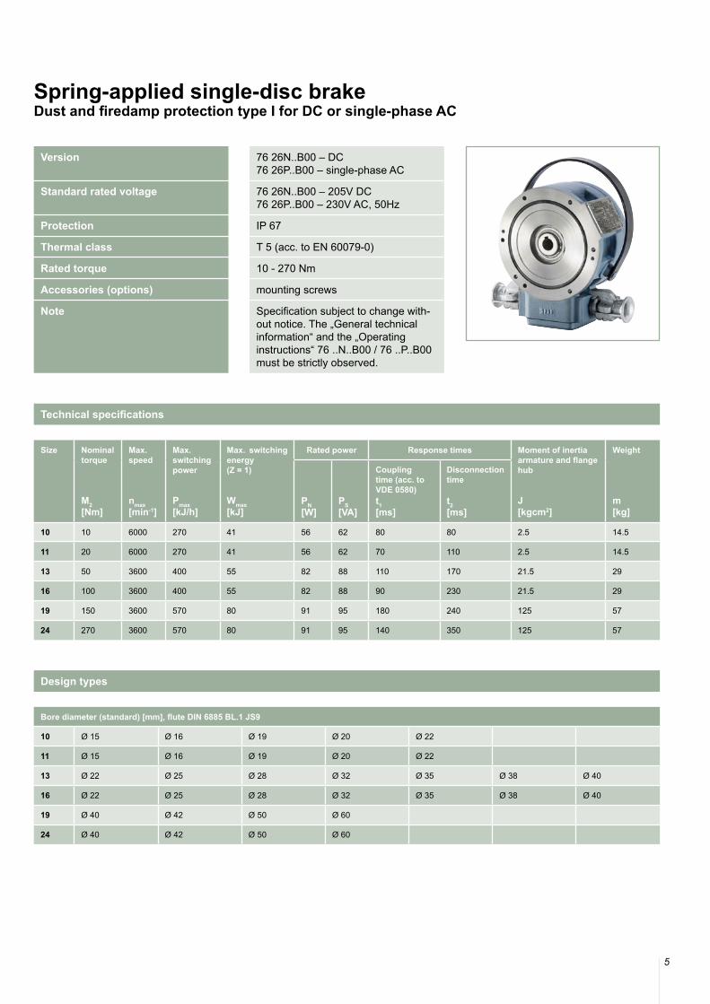
Version 76 26N..B00 – DC76 26P..B00 – single-phase AC
Standard rated voltage 76 26N..B00 – 205V DC76 26P..B00 – 230V AC, 50Hz
Protection IP 67
Thermal class T 5 (acc. to EN 60079-0)
Rated torque 10 - 270 Nm
Accessories (options) mounting screws
Note Specification subject to change with-out notice. The „General technical information“ and the „Operating instructions“ 76 ..N..B00 / 76 ..P..B00 must be strictly observed.
Spring-applied single-disc brakeDust and firedamp protection type I for DC or single-phase AC
Technical specifications
Bore diameter (standard) [mm], flute DIN 6885 BL.1 JS9
10 Ø 15 Ø 16 Ø 19 Ø 20 Ø 22
11 Ø 15 Ø 16 Ø 19 Ø 20 Ø 22
13 Ø 22 Ø 25 Ø 28 Ø 32 Ø 35 Ø 38 Ø 40
16 Ø 22 Ø 25 Ø 28 Ø 32 Ø 35 Ø 38 Ø 40
19 Ø 40 Ø 42 Ø 50 Ø 60
24 Ø 40 Ø 42 Ø 50 Ø 60
Design types
Size Nominal torque
M2 [Nm]
Max. speed
nmax[min-1]
Max. switching power
Pmax[kJ/h]
Max. switching energy (Z = 1)
Wmax[kJ]
Rated power Response times Moment of inertia armature and flange hub
J[kgcm2]
Weight
m[kg]
PN[W]
PS[VA]
Couplingtime (acc. to VDE 0580)t1[ms]
Disconnection time
t2[ms]
10 10 6000 270 41 56 62 80 80 2.5 14.5
11 20 6000 270 41 56 62 70 110 2.5 14.5
13 50 3600 400 55 82 88 110 170 21.5 29
16 100 3600 400 55 82 88 90 230 21.5 29
19 150 3600 570 80 91 95 180 240 125 57
24 270 3600 570 80 91 95 140 350 125 57
6
EEX Line
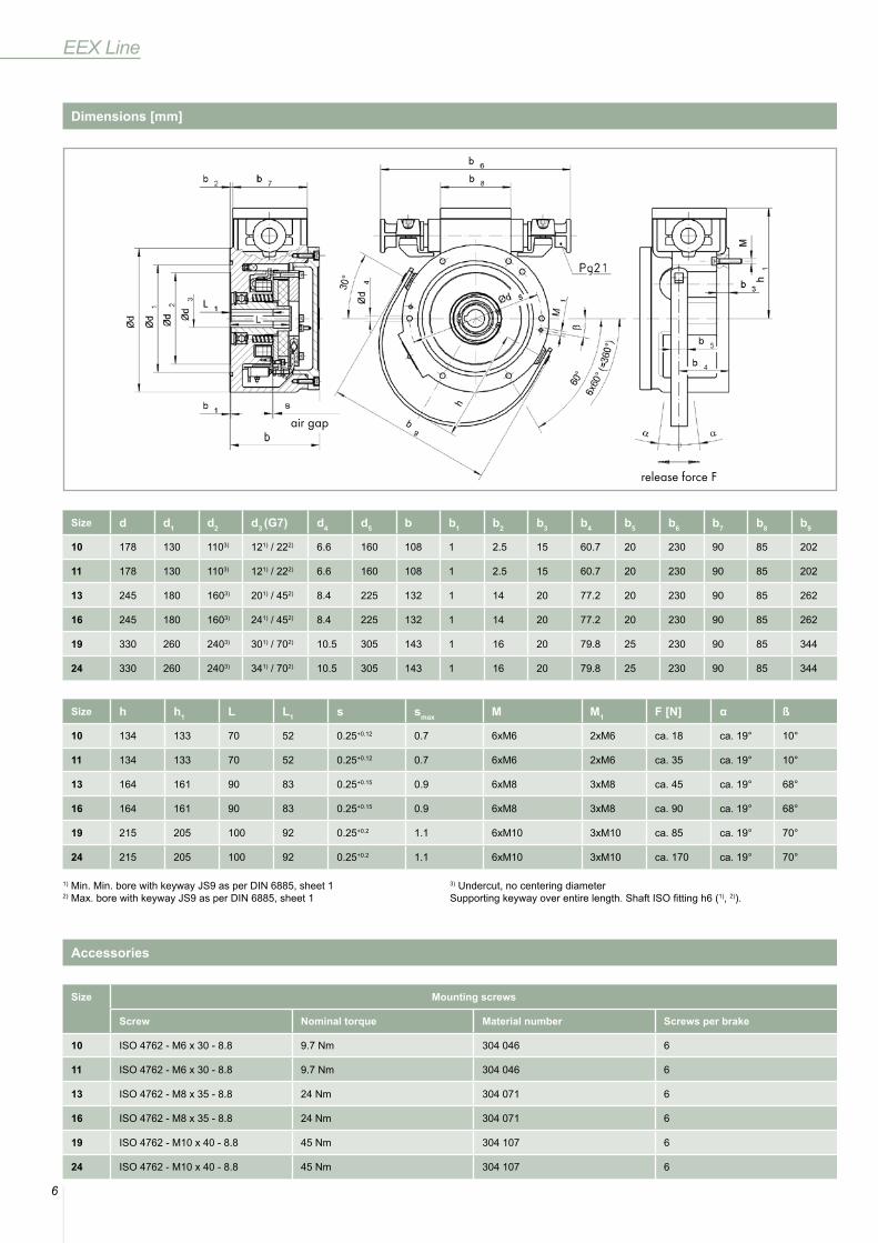
Size d d1 d2 d3 (G7) d4 d5 b b1 b2 b3 b4 b5 b6 b7 b8 b9
10 178 130 1103) 121) / 222) 6.6 160 108 1 2.5 15 60.7 20 230 90 85 202
11 178 130 1103) 121) / 222) 6.6 160 108 1 2.5 15 60.7 20 230 90 85 202
13 245 180 1603) 201) / 452) 8.4 225 132 1 14 20 77.2 20 230 90 85 262
16 245 180 1603) 241) / 452) 8.4 225 132 1 14 20 77.2 20 230 90 85 262
19 330 260 2403) 301) / 702) 10.5 305 143 1 16 20 79.8 25 230 90 85 344
24 330 260 2403) 341) / 702) 10.5 305 143 1 16 20 79.8 25 230 90 85 344
Size h h1 L L1 s smax M M1 F [N] α ß
10 134 133 70 52 0.25+0.12 0.7 6xM6 2xM6 ca. 18 ca. 19° 10°
11 134 133 70 52 0.25+0.12 0.7 6xM6 2xM6 ca. 35 ca. 19° 10°
13 164 161 90 83 0.25+0.15 0.9 6xM8 3xM8 ca. 45 ca. 19° 68°
16 164 161 90 83 0.25+0.15 0.9 6xM8 3xM8 ca. 90 ca. 19° 68°
19 215 205 100 92 0.25+0.2 1.1 6xM10 3xM10 ca. 85 ca. 19° 70°
24 215 205 100 92 0.25+0.2 1.1 6xM10 3xM10 ca. 170 ca. 19° 70°
1) Min. Min. bore with keyway JS9 as per DIN 6885, sheet 12) Max. bore with keyway JS9 as per DIN 6885, sheet 1
3) Undercut, no centering diameterSupporting keyway over entire length. Shaft ISO fitting h6 (1), 2)).
Size Mounting screws
Screw Nominal torque Material number Screws per brake
10 ISO 4762 - M6 x 30 - 8.8 9.7 Nm 304 046 6
11 ISO 4762 - M6 x 30 - 8.8 9.7 Nm 304 046 6
13 ISO 4762 - M8 x 35 - 8.8 24 Nm 304 071 6
16 ISO 4762 - M8 x 35 - 8.8 24 Nm 304 071 6
19 ISO 4762 - M10 x 40 - 8.8 45 Nm 304 107 6
24 ISO 4762 - M10 x 40 - 8.8 45 Nm 304 107 6
Dimensions [mm]
Accessories
release force F
air gap
7
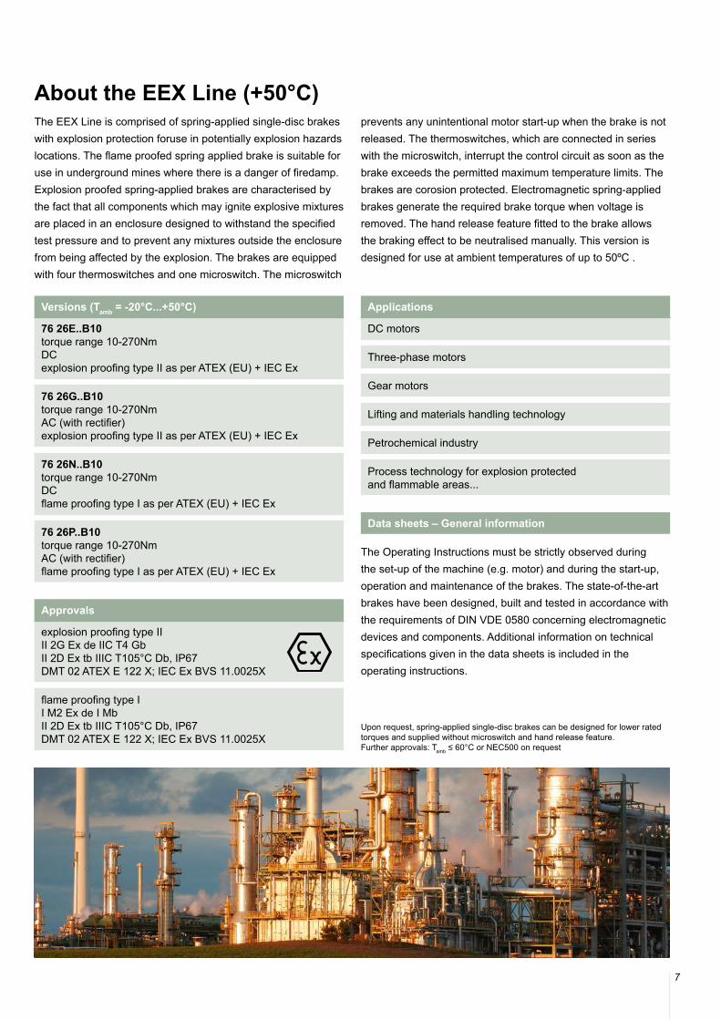
About the EEX Line (+50°C)The EEX Line is comprised of spring-applied single-disc brakes with explosion protection foruse in potentially explosion hazards locations. The flame proofed spring applied brake is suitable for use in underground mines where there is a danger of firedamp. Explosion proofed spring-applied brakes are characterised by the fact that all components which may ignite explosive mixtures are placed in an enclosure designed to withstand the specified test pressure and to prevent any mixtures outside the enclosure from being affected by the explosion. The brakes are equipped with four thermoswitches and one microswitch. The microswitch
prevents any unintentional motor start-up when the brake is not released. The thermoswitches, which are connected in series with the microswitch, interrupt the control circuit as soon as the brake exceeds the permitted maximum temperature limits. The brakes are corosion protected. Electromagnetic spring-applied brakes generate the required brake torque when voltage is removed. The hand release feature fitted to the brake allows the braking effect to be neutralised manually. This version is designed for use at ambient temperatures of up to 50ºC .
The Operating Instructions must be strictly observed during the set-up of the machine (e.g. motor) and during the start-up, operation and maintenance of the brakes. The state-of-the-art brakes have been designed, built and tested in accordance with the requirements of DIN VDE 0580 concerning electromagnetic devices and components. Additional information on technical specifications given in the data sheets is included in the operating instructions.
Data sheets – General information
Versions (Tamb = -20°C...+50°C)
76 26E..B10 torque range 10-270NmDCexplosion proofing type II as per ATEX (EU) + IEC Ex
76 26G..B10 torque range 10-270NmAC (with rectifier)explosion proofing type II as per ATEX (EU) + IEC Ex
76 26N..B10 torque range 10-270NmDCflame proofing type I as per ATEX (EU) + IEC Ex
76 26P..B10torque range 10-270NmAC (with rectifier)flame proofing type I as per ATEX (EU) + IEC Ex
Applications
DC motors
Three-phase motors
Gear motors
Lifting and materials handling technology
Petrochemical industry
Process technology for explosion protected and flammable areas...
Approvals
explosion proofing type IIII 2G Ex de IIC T4 GbII 2D Ex tb IIIC T105°C Db, IP67DMT 02 ATEX E 122 X; IEC Ex BVS 11.0025X
flame proofing type II M2 Ex de I MbII 2D Ex tb IIIC T105°C Db, IP67DMT 02 ATEX E 122 X; IEC Ex BVS 11.0025X
Upon request, spring-applied single-disc brakes can be designed for lower rated torques and supplied without microswitch and hand release feature.Further approvals: Tamb ≤ 60°C or NEC500 on request
8
EEX Line (+50°C)
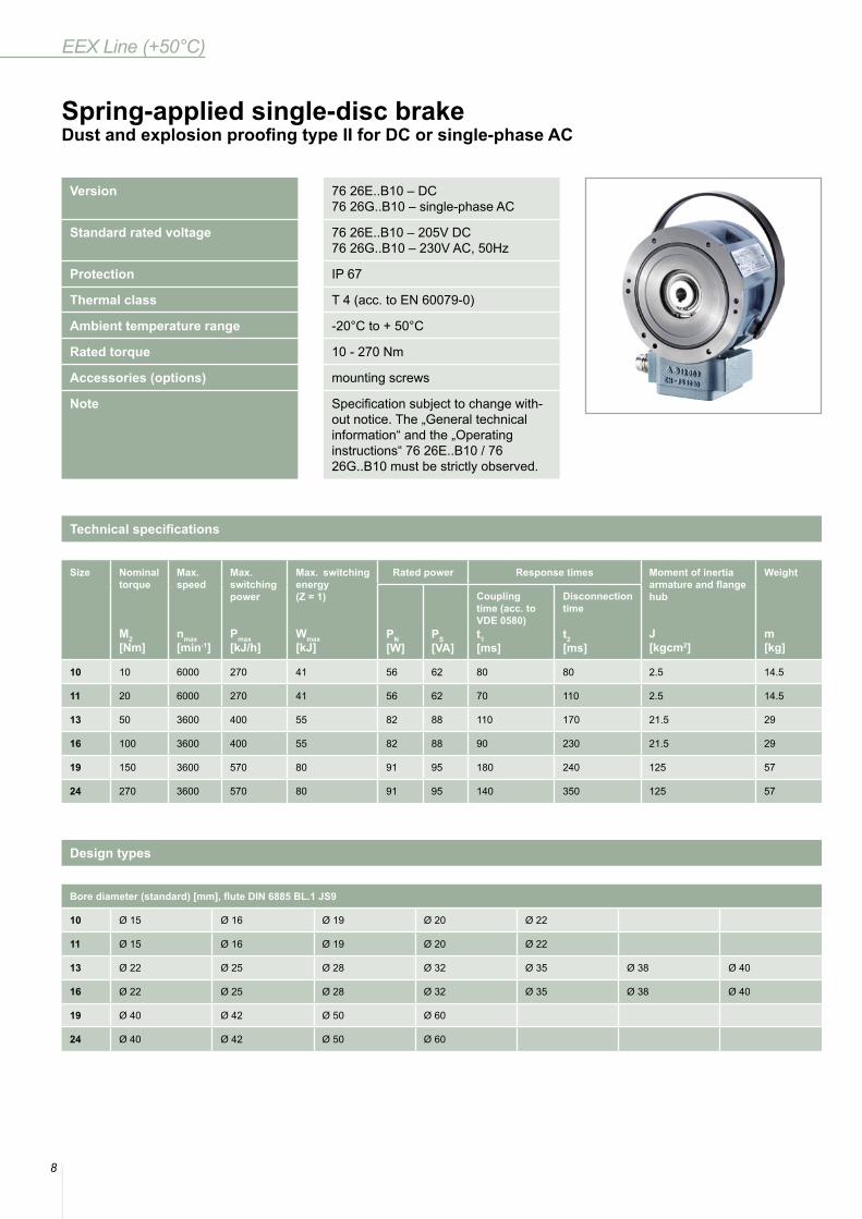
Version 76 26E..B10 – DC76 26G..B10 – single-phase AC
Standard rated voltage 76 26E..B10 – 205V DC76 26G..B10 – 230V AC, 50Hz
Protection IP 67
Thermal class T 4 (acc. to EN 60079-0)
Ambient temperature range -20°C to + 50°C
Rated torque 10 - 270 Nm
Accessories (options) mounting screws
Note Specification subject to change with-out notice. The „General technical information“ and the „Operating instructions“ 76 26E..B10 / 7626G..B10 must be strictly observed.
Spring-applied single-disc brakeDust and explosion proofing type II for DC or single-phase AC
Bore diameter (standard) [mm], flute DIN 6885 BL.1 JS9
10 Ø 15 Ø 16 Ø 19 Ø 20 Ø 22
11 Ø 15 Ø 16 Ø 19 Ø 20 Ø 22
13 Ø 22 Ø 25 Ø 28 Ø 32 Ø 35 Ø 38 Ø 40
16 Ø 22 Ø 25 Ø 28 Ø 32 Ø 35 Ø 38 Ø 40
19 Ø 40 Ø 42 Ø 50 Ø 60
24 Ø 40 Ø 42 Ø 50 Ø 60
Design types
Technical specifications
Size Nominal torque
M2 [Nm]
Max. speed
nmax[min-1]
Max. switching power
Pmax[kJ/h]
Max. switching energy (Z = 1)
Wmax[kJ]
Rated power Response times Moment of inertia armature and flange hub
J[kgcm2]
Weight
m[kg]
PN[W]
PS[VA]
Couplingtime (acc. to VDE 0580)t1[ms]
Disconnection time
t2[ms]
10 10 6000 270 41 56 62 80 80 2.5 14.5
11 20 6000 270 41 56 62 70 110 2.5 14.5
13 50 3600 400 55 82 88 110 170 21.5 29
16 100 3600 400 55 82 88 90 230 21.5 29
19 150 3600 570 80 91 95 180 240 125 57
24 270 3600 570 80 91 95 140 350 125 57
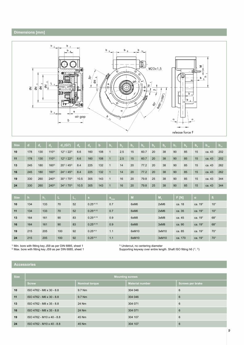
9
Size d d1 d2 d3 (G7) d4 d5 b b1 b2 b3 b4 b5 b6 b7 b8 b9 b10 b11
10 178 130 1103) 121) / 222) 6.6 160 108 1 2.5 15 60.7 20 38 90 85 15 ca. 43 202
11 178 130 1103) 121) / 222) 6.6 160 108 1 2.5 15 60.7 20 38 90 85 15 ca. 43 202
13 245 180 1603) 201) / 452) 8.4 225 132 1 14 20 77.2 20 38 90 85 15 ca. 43 262
16 245 180 1603) 241) / 452) 8.4 225 132 1 14 20 77.2 20 38 90 85 15 ca. 43 262
19 330 260 2403) 301) / 702) 10.5 305 143 1 16 20 79.8 25 38 90 85 15 ca. 43 344
24 330 260 2403) 341) / 702) 10.5 305 143 1 16 20 79.8 25 38 90 85 15 ca. 43 344
Size h h1 L L1 s smax M M1 F [N] α ß
10 134 133 70 52 0.25+0.12 0.7 6xM6 2xM6 ca. 18 ca. 19° 10°
11 134 133 70 52 0.25+0.12 0.7 6xM6 2xM6 ca. 35 ca. 19° 10°
13 164 161 90 83 0.25+0.15 0.9 6xM8 3xM8 ca. 45 ca. 19° 68°
16 164 161 90 83 0.25+0.15 0.9 6xM8 3xM8 ca. 90 ca. 19° 68°
19 215 205 100 92 0.25+0.2 1.1 6xM10 3xM10 ca. 85 ca. 19° 70°
24 215 205 100 92 0.25+0.2 1.1 6xM10 3xM10 ca. 170 ca. 19° 70°
1) Min. bore with fitting key JS9 as per DIN 6885, sheet 12) Max. bore with fitting key JS9 as per DIN 6885, sheet 1
3) Undercut, no centering diameterSupporting keyway over entire length. Shaft ISO fitting h6 (1), 2))
Size Mounting screws
Screw Nominal torque Material number Screws per brake
10 ISO 4762 - M6 x 30 - 8.8 9.7 Nm 304 046 6
11 ISO 4762 - M6 x 30 - 8.8 9.7 Nm 304 046 6
13 ISO 4762 - M8 x 35 - 8.8 24 Nm 304 071 6
16 ISO 4762 - M8 x 35 - 8.8 24 Nm 304 071 6
19 ISO 4762 - M10 x 40 - 8.8 45 Nm 304 107 6
24 ISO 4762 - M10 x 40 - 8.8 45 Nm 304 107 6
Dimensions [mm]
Accessories
release force F
air gap
10
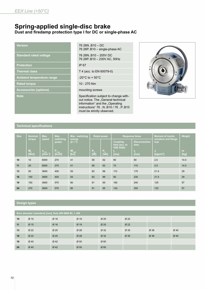
EEX Line (+50°C)
Version 76 26N..B10 – DC76 26P..B10 – single-phase AC
Standard rated voltage 76 26N..B10 – 205V DC76 26P..B10 – 230V AC, 50Hz
Protection IP 67
Thermal class T 4 (acc. to EN 60079-0)
Ambient temperature range -20°C to + 50°C
Rated torque 10 - 270 Nm
Accessories (options) mounting screws
Note Specification subject to change with-out notice. The „General technical information“ and the „Operating instructions“ 76 ..N..B10 / 76 ..P..B10 must be strictly observed.
Spring-applied single-disc brakeDust and firedamp protection type I for DC or single-phase AC
Technical specifications
Bore diameter (standard) [mm], flute DIN 6885 BL.1 JS9
10 Ø 15 Ø 16 Ø 19 Ø 20 Ø 22
11 Ø 15 Ø 16 Ø 19 Ø 20 Ø 22
13 Ø 22 Ø 25 Ø 28 Ø 32 Ø 35 Ø 38 Ø 40
16 Ø 22 Ø 25 Ø 28 Ø 32 Ø 35 Ø 38 Ø 40
19 Ø 40 Ø 42 Ø 50 Ø 60
24 Ø 40 Ø 42 Ø 50 Ø 60
Design types
Size Nominal torque
M2 [Nm]
Max. speed
nmax[min-1]
Max. switching power
Pmax[kJ/h]
Max. switching energy (Z = 1)
Wmax[kJ]
Rated power Response times Moment of inertia armature and flange hub
J[kgcm2]
Weight
m[kg]
PN[W]
PS[VA]
Couplingtime (acc. to VDE 0580)t1[ms]
Disconnection time
t2[ms]
10 10 6000 270 41 56 62 80 80 2.5 14.5
11 20 6000 270 41 56 62 70 110 2.5 14.5
13 50 3600 400 55 82 88 110 170 21.5 29
16 100 3600 400 55 82 88 90 230 21.5 29
19 150 3600 570 80 91 95 180 240 125 57
24 270 3600 570 80 91 95 140 350 125 57
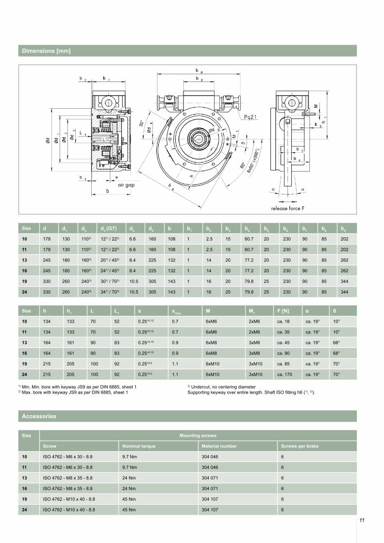
11
Size d d1 d2 d3 (G7) d4 d5 b b1 b2 b3 b4 b5 b6 b7 b8 b9
10 178 130 1103) 121) / 222) 6.6 160 108 1 2.5 15 60.7 20 230 90 85 202
11 178 130 1103) 121) / 222) 6.6 160 108 1 2.5 15 60.7 20 230 90 85 202
13 245 180 1603) 201) / 452) 8.4 225 132 1 14 20 77.2 20 230 90 85 262
16 245 180 1603) 241) / 452) 8.4 225 132 1 14 20 77.2 20 230 90 85 262
19 330 260 2403) 301) / 702) 10.5 305 143 1 16 20 79.8 25 230 90 85 344
24 330 260 2403) 341) / 702) 10.5 305 143 1 16 20 79.8 25 230 90 85 344
Size h h1 L L1 s smax M M1 F [N] α ß
10 134 133 70 52 0.25+0.12 0.7 6xM6 2xM6 ca. 18 ca. 19° 10°
11 134 133 70 52 0.25+0.12 0.7 6xM6 2xM6 ca. 35 ca. 19° 10°
13 164 161 90 83 0.25+0.15 0.9 6xM8 3xM8 ca. 45 ca. 19° 68°
16 164 161 90 83 0.25+0.15 0.9 6xM8 3xM8 ca. 90 ca. 19° 68°
19 215 205 100 92 0.25+0.2 1.1 6xM10 3xM10 ca. 85 ca. 19° 70°
24 215 205 100 92 0.25+0.2 1.1 6xM10 3xM10 ca. 170 ca. 19° 70°
1) Min. Min. bore with keyway JS9 as per DIN 6885, sheet 12) Max. bore with keyway JS9 as per DIN 6885, sheet 1
3) Undercut, no centering diameterSupporting keyway over entire length. Shaft ISO fitting h6 (1), 2)).
Size Mounting screws
Screw Nominal torque Material number Screws per brake
10 ISO 4762 - M6 x 30 - 8.8 9.7 Nm 304 046 6
11 ISO 4762 - M6 x 30 - 8.8 9.7 Nm 304 046 6
13 ISO 4762 - M8 x 35 - 8.8 24 Nm 304 071 6
16 ISO 4762 - M8 x 35 - 8.8 24 Nm 304 071 6
19 ISO 4762 - M10 x 40 - 8.8 45 Nm 304 107 6
24 ISO 4762 - M10 x 40 - 8.8 45 Nm 304 107 6
Dimensions [mm]
Accessories
release force F
air gap
12
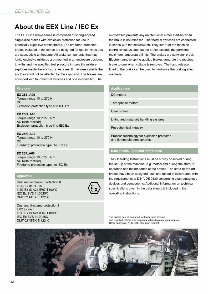
EEX Line / IEC Ex
About the EEX Line / IEC ExThe EEX Line brake series is comprised of spring-applied single-disc brakes with explosion protection for use in potentially explosive atmospheres. The firedamp-protected brakes included in the series are designed for use in mines that are susceptible to firedamp. All brake components that may ignite explosive mixtures are mounted in an enclosure designed to withstand the specified test pressure in case the mixture explodes inside the enclosure. As a result, mixtures outside the enclosure will not be affected by the explosion. The brakes are equipped with four thermal switches and one microswitch. The
microswitch prevents any unintentional motor start-up when the brake is not released. The thermal switches are connected in series with the microswitch. They interrupt the machine control circuit as soon as the brake exceeds the permitted maximum temperature limits. The brakes are saltwater-proof. Electromagnetic spring-applied brakes generate the required brake torque when voltage is removed. The hand release fitted to the brake can be used to neutralise the braking effect manually.
The Operating Instructions must be strictly observed during the set-up of the machine (e.g. motor) and during the start-up, operation and maintenance of the brakes. The state-of-the-art brakes have been designed, built and tested in accordance with the requirements of DIN VDE 0580 concerning electromagnetic devices and components. Additional information on technical specifications given in the data sheets is included in the operating instructions.
Data sheets – General information
The brakes can be designed for lower rated torques and supplied without microswitch and hand release upon request.Other approvals: NEC 500 / 505 upon request
Versions
EX 26E..A00 Torque range 10 to 270 NmDCExplosion protection type II to IEC Ex
EX 26G..A00 Torque range 10 to 270 NmAC (with rectifier)Explosion protection type II to IEC Ex
EX 26N..A00 Torque range 10 to 270 NmDCFiredamp protection type I to IEC Ex
EX 26P..A00Torque range 10 to 270 NmAC (with rectifier)Firedamp protection type I to IEC Ex
Applications
DC motors
Threephase motors
Gear motors
Lifting and materials handling systems
Petrochemical industry
Process technology for explosion protected and flammable atmospheres...
Approvals
Dust and explosion protection IIII 2G Ex de IIC T5II 2D Ex tD A21 IP67 T100°CIEC Ex BVS 11.0025XDMT 02 ATEX E 122 X
Dust and firedamp protection II M2 Ex de III 2D Ex tD A21 IP67 T100°CIEC Ex BVS 11.0025XDMT 02 ATEX E 122 X
13
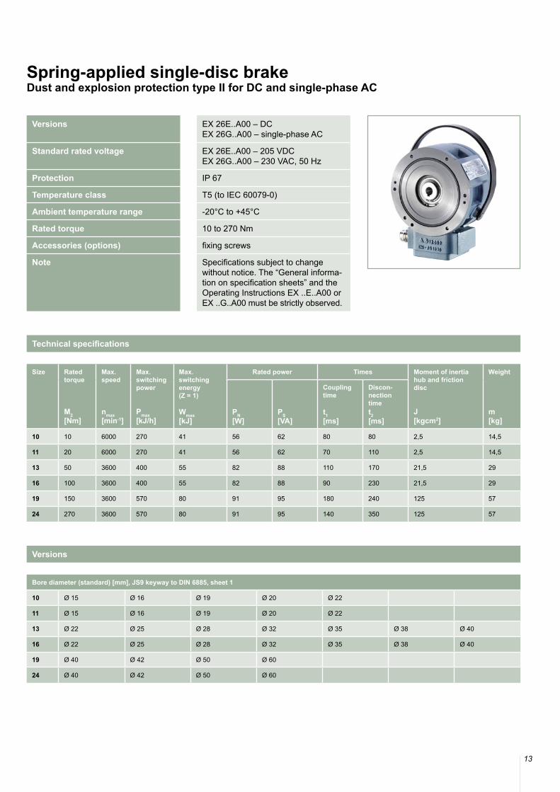
Versions EX 26E..A00 – DCEX 26G..A00 – single-phase AC
Standard rated voltage EX 26E..A00 – 205 VDCEX 26G..A00 – 230 VAC, 50 Hz
Protection IP 67
Temperature class T5 (to IEC 60079-0)
Ambient temperature range -20°C to +45°C
Rated torque 10 to 270 Nm
Accessories (options) fixing screws
Note Specifications subject to change without notice. The “General informa-tion on specification sheets” and the Operating Instructions EX ..E..A00 or EX ..G..A00 must be strictly observed.
Spring-applied single-disc brakeDust and explosion protection type II for DC and single-phase AC
Size Rated torque
M2 [Nm]
Max. speed
nmax[min-1]
Max. switching power
Pmax[kJ/h]
Max. switchingenergy(Z = 1)
Wmax[kJ]
Rated power Times Moment of inertiahub and frictiondisc
J[kgcm2]
Weight
m[kg]
PN[W]
PS[VA]
Coupling time
t1[ms]
Discon-nection timet2[ms]
10 10 6000 270 41 56 62 80 80 2,5 14,5
11 20 6000 270 41 56 62 70 110 2,5 14,5
13 50 3600 400 55 82 88 110 170 21,5 29
16 100 3600 400 55 82 88 90 230 21,5 29
19 150 3600 570 80 91 95 180 240 125 57
24 270 3600 570 80 91 95 140 350 125 57
Technical specifications
Bore diameter (standard) [mm], JS9 keyway to DIN 6885, sheet 1
10 Ø 15 Ø 16 Ø 19 Ø 20 Ø 22
11 Ø 15 Ø 16 Ø 19 Ø 20 Ø 22
13 Ø 22 Ø 25 Ø 28 Ø 32 Ø 35 Ø 38 Ø 40
16 Ø 22 Ø 25 Ø 28 Ø 32 Ø 35 Ø 38 Ø 40
19 Ø 40 Ø 42 Ø 50 Ø 60
24 Ø 40 Ø 42 Ø 50 Ø 60
Versions

14
EEX Line / IEC Ex
Size d d1 d2 d3 (G7) d4 d5 b b1 b2 b3 b4 b5 b6 b7 b8 b9 b10 b11
10 178 130 1103) 121) / 222) 6,6 160 108 1 2,5 15 60,7 20 38 90 85 15 ca. 43 202
11 178 130 1103) 121) / 222) 6,6 160 108 1 2,5 15 60,7 20 38 90 85 15 ca. 43 202
13 245 180 1603) 201) / 452) 8,4 225 132 1 14 20 77,2 20 38 90 85 15 ca. 43 262
16 245 180 1603) 241) / 452) 8,4 225 132 1 14 20 77,2 20 38 90 85 15 ca. 43 262
19 330 260 2403) 301) / 702) 10,5 305 143 1 16 20 79,8 25 38 90 85 15 ca. 43 344
24 330 260 2403) 341) / 702) 10,5 305 143 1 16 20 79,8 25 38 90 85 15 ca. 43 344
Size h h1 L L1 s smax M M1 F [N] α ß
10 134 133 70 52 0,25+0,12 0,7 6xM6 2xM6 ca. 18 ca. 19° 10°
11 134 133 70 52 0,25+0,12 0,7 6xM6 2xM6 ca. 35 ca. 19° 10°
13 164 161 90 83 0,25+0,15 0,9 6xM8 3xM8 ca. 45 ca. 19° 68°
16 164 161 90 83 0,25+0,15 0,9 6xM8 3xM8 ca. 90 ca. 19° 68°
19 215 205 100 92 0,25+0,2 1,1 6xM10 3xM10 ca. 85 ca. 19° 70°
24 215 205 100 92 0,25+0,2 1,1 6xM10 3xM10 ca. 170 ca. 19° 70°
1) Min. bore, with JS9 keyway to DIN 6885, sheet 12) Max. bore, with JS9 keyway to DIN 6885, sheet 1
3) Undercut, no centring diameterSupporting feather key over entire length, shaft with ISO “h6” fit (1), 2)).
Size Fixing screws
Screw Tightening torque Order number Screws per brake
10 ISO 4762 - M6 x 30 - 8.8 9,7 Nm 304 046 6
11 ISO 4762 - M6 x 30 - 8.8 9,7 Nm 304 046 6
13 ISO 4762 - M8 x 35 - 8.8 24 Nm 304 071 6
16 ISO 4762 - M8 x 35 - 8.8 24 Nm 304 071 6
19 ISO 4762 - M10 x 40 - 8.8 45 Nm 304 107 6
24 ISO 4762 - M10 x 40 - 8.8 45 Nm 304 107 6
Dimensions [mm]
Accessories
air gap
release force F
15
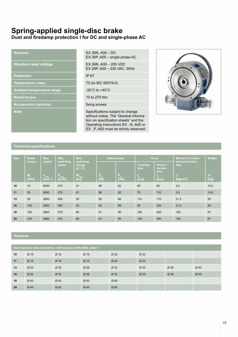
Versions EX 26N..A00 – DCEX 26P..A00 – single-phase AC
Standard rated voltage EX 26N..A00 – 205 VDCEX 26P..A00 – 230 VAC, 50Hz
Protection IP 67
Temperature class T5 (to IEC 60079-0)
Ambient temperature range -20°C to +45°C
Rated torque 10 to 270 Nm
Accessories (options) fixing screws
Note Specifications subject to change without notice. The “General informa-tion on specification sheets” and the Operating Instructions EX ..N..A00 or EX ..P..A00 must be strictly observed.
Spring-applied single-disc brakeDust and firedamp protection I for DC and single-phase AC
Size Rated torque
M2 [Nm]
Max. speed
nmax[min-1]
Max. switching power
Pmax[kJ/h]
Max. switchingenergy(Z = 1)
Wmax[kJ]
Rated power Times Moment of inertiahub and frictiondisc
J[kgcm2]
Weight
m[kg]
PN[W]
PS[VA]
Coupling time
t1[ms]
Discon-nection timet2[ms]
10 10 6000 270 41 56 62 80 80 2,5 14,5
11 20 6000 270 41 56 62 70 110 2,5 14,5
13 50 3600 400 55 82 88 110 170 21,5 29
16 100 3600 400 55 82 88 90 230 21,5 29
19 150 3600 570 80 91 95 180 240 125 57
24 270 3600 570 80 91 95 140 350 125 57
Technical specifications
Bore diameter (standard) [mm], JS9 keyway to DIN 6885, sheet 1
10 Ø 15 Ø 16 Ø 19 Ø 20 Ø 22
11 Ø 15 Ø 16 Ø 19 Ø 20 Ø 22
13 Ø 22 Ø 25 Ø 28 Ø 32 Ø 35 Ø 38 Ø 40
16 Ø 22 Ø 25 Ø 28 Ø 32 Ø 35 Ø 38 Ø 40
19 Ø 40 Ø 42 Ø 50 Ø 60
24 Ø 40 Ø 42 Ø 50 Ø 60
Versions

16
EEX Line / IEC Ex
Size d d1 d2 d3 (G7) d4 d5 b b1 b2 b3 b4 b5 b6 b7 b8 b9
10 178 130 1103) 121) / 222) 6,6 160 108 1 2,5 15 60,7 20 230 90 85 202
11 178 130 1103) 121) / 222) 6,6 160 108 1 2,5 15 60,7 20 230 90 85 202
13 245 180 1603) 201) / 452) 8,4 225 132 1 14 20 77,2 20 230 90 85 262
16 245 180 1603) 241) / 452) 8,4 225 132 1 14 20 77,2 20 230 90 85 262
19 330 260 2403) 301) / 702) 10,5 305 143 1 16 20 79,8 25 230 90 85 344
24 330 260 2403) 341) / 702) 10,5 305 143 1 16 20 79,8 25 230 90 85 344
Size h h1 L L1 s smax M M1 F [N] α ß
10 134 133 70 52 0,25+0,12 0,7 6xM6 2xM6 ca. 18 ca. 19° 10°
11 134 133 70 52 0,25+0,12 0,7 6xM6 2xM6 ca. 35 ca. 19° 10°
13 164 161 90 83 0,25+0,15 0,9 6xM8 3xM8 ca. 45 ca. 19° 68°
16 164 161 90 83 0,25+0,15 0,9 6xM8 3xM8 ca. 90 ca. 19° 68°
19 215 205 100 92 0,25+0,2 1,1 6xM10 3xM10 ca. 85 ca. 19° 70°
24 215 205 100 92 0,25+0,2 1,1 6xM10 3xM10 ca. 170 ca. 19° 70°
1) Min. bore, with JS9 keyway to DIN 6885, sheet 12) Max. bore, with JS9 keyway to DIN 6885, sheet 1
3) Undercut, no centring diameterSupporting feather key over entire length, shaft with ISO “h6” fit (1), 2)).
Size Fixing screws
Screw Tightening torque Order number Screws per brake
10 ISO 4762 - M6 x 30 - 8.8 9,7 Nm 304 046 6
11 ISO 4762 - M6 x 30 - 8.8 9,7 Nm 304 046 6
13 ISO 4762 - M8 x 35 - 8.8 24 Nm 304 071 6
16 ISO 4762 - M8 x 35 - 8.8 24 Nm 304 071 6
19 ISO 4762 - M10 x 40 - 8.8 45 Nm 304 107 6
24 ISO 4762 - M10 x 40 - 8.8 45 Nm 304 107 6
Dimensions [mm]
Accessories
air gap
release force F
17
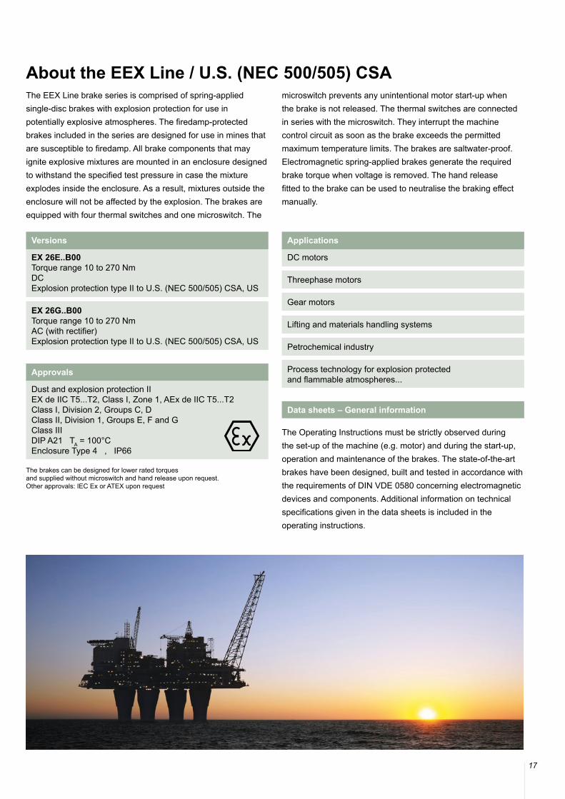
About the EEX Line / U.S. (NEC 500/505) CSAThe EEX Line brake series is comprised of spring-applied single-disc brakes with explosion protection for use in potentially explosive atmospheres. The firedamp-protected brakes included in the series are designed for use in mines that are susceptible to firedamp. All brake components that may ignite explosive mixtures are mounted in an enclosure designed to withstand the specified test pressure in case the mixture explodes inside the enclosure. As a result, mixtures outside the enclosure will not be affected by the explosion. The brakes are equipped with four thermal switches and one microswitch. The
microswitch prevents any unintentional motor start-up when the brake is not released. The thermal switches are connected in series with the microswitch. They interrupt the machine control circuit as soon as the brake exceeds the permitted maximum temperature limits. The brakes are saltwater-proof. Electromagnetic spring-applied brakes generate the required brake torque when voltage is removed. The hand release fitted to the brake can be used to neutralise the braking effect manually.
The Operating Instructions must be strictly observed during the set-up of the machine (e.g. motor) and during the start-up, operation and maintenance of the brakes. The state-of-the-art brakes have been designed, built and tested in accordance with the requirements of DIN VDE 0580 concerning electromagnetic devices and components. Additional information on technical specifications given in the data sheets is included in the operating instructions.
Data sheets – General information
The brakes can be designed for lower rated torques and supplied without microswitch and hand release upon request.Other approvals: IEC Ex or ATEX upon request
Versions
EX 26E..B00 Torque range 10 to 270 NmDCExplosion protection type II to U.S. (NEC 500/505) CSA, US
EX 26G..B00 Torque range 10 to 270 NmAC (with rectifier)Explosion protection type II to U.S. (NEC 500/505) CSA, US
Applications
DC motors
Threephase motors
Gear motors
Lifting and materials handling systems
Petrochemical industry
Process technology for explosion protected and flammable atmospheres...
Approvals
Dust and explosion protection IIEX de IIC T5...T2, Class I, Zone 1, AEx de IIC T5...T2Class I, Division 2, Groups C, DClass II, Division 1, Groups E, F and GClass IIIDIP A21 TA = 100°CEnclosure Type 4 , IP66
18
EEX Line / U.S. (NEC 500/505) CSA
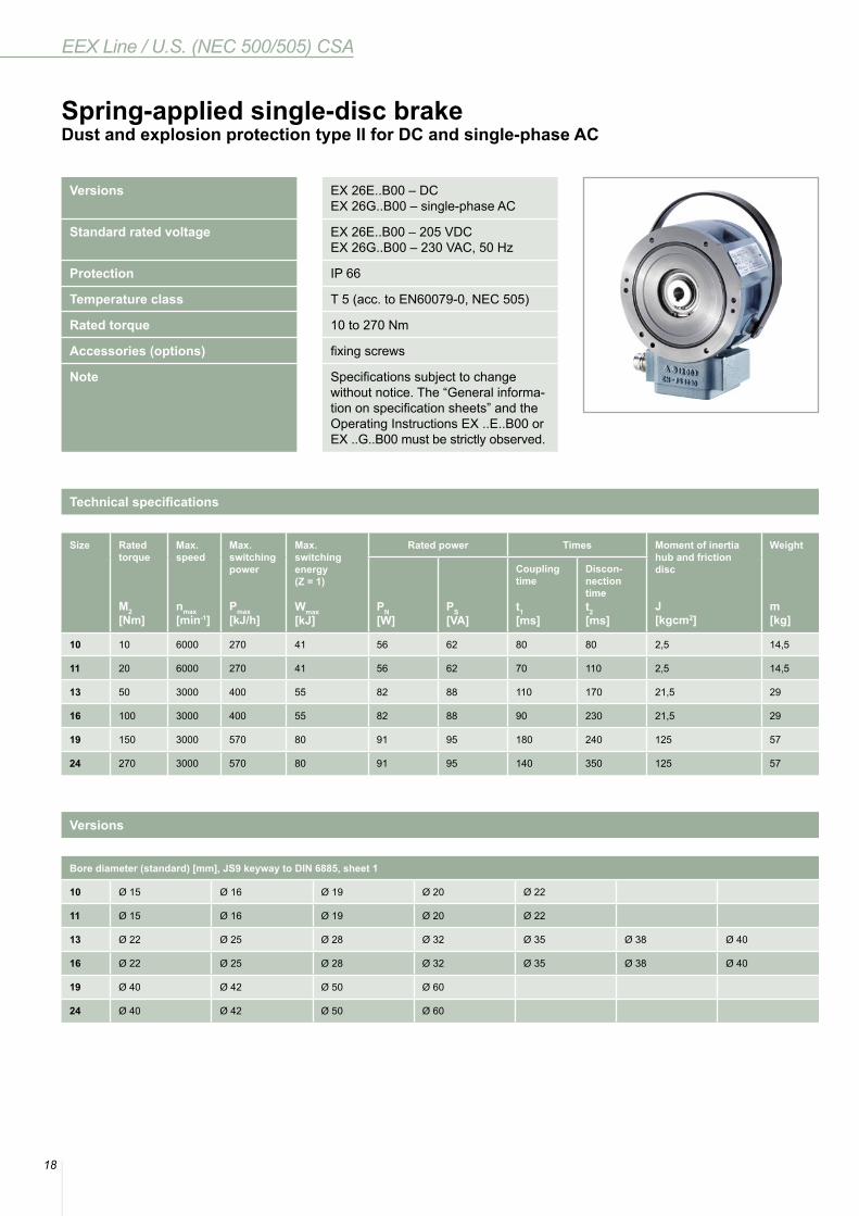
Versions EX 26E..B00 – DCEX 26G..B00 – single-phase AC
Standard rated voltage EX 26E..B00 – 205 VDCEX 26G..B00 – 230 VAC, 50 Hz
Protection IP 66
Temperature class T 5 (acc. to EN60079-0, NEC 505)
Rated torque 10 to 270 Nm
Accessories (options) fixing screws
Note Specifications subject to change without notice. The “General informa-tion on specification sheets” and the Operating Instructions EX ..E..B00 or EX ..G..B00 must be strictly observed.
Spring-applied single-disc brakeDust and explosion protection type II for DC and single-phase AC
Size Rated torque
M2 [Nm]
Max. speed
nmax[min-1]
Max. switching power
Pmax[kJ/h]
Max. switchingenergy(Z = 1)
Wmax[kJ]
Rated power Times Moment of inertiahub and frictiondisc
J[kgcm2]
Weight
m[kg]
PN[W]
PS[VA]
Coupling time
t1[ms]
Discon-nection timet2[ms]
10 10 6000 270 41 56 62 80 80 2,5 14,5
11 20 6000 270 41 56 62 70 110 2,5 14,5
13 50 3000 400 55 82 88 110 170 21,5 29
16 100 3000 400 55 82 88 90 230 21,5 29
19 150 3000 570 80 91 95 180 240 125 57
24 270 3000 570 80 91 95 140 350 125 57
Technical specifications
Bore diameter (standard) [mm], JS9 keyway to DIN 6885, sheet 1
10 Ø 15 Ø 16 Ø 19 Ø 20 Ø 22
11 Ø 15 Ø 16 Ø 19 Ø 20 Ø 22
13 Ø 22 Ø 25 Ø 28 Ø 32 Ø 35 Ø 38 Ø 40
16 Ø 22 Ø 25 Ø 28 Ø 32 Ø 35 Ø 38 Ø 40
19 Ø 40 Ø 42 Ø 50 Ø 60
24 Ø 40 Ø 42 Ø 50 Ø 60
Versions
19
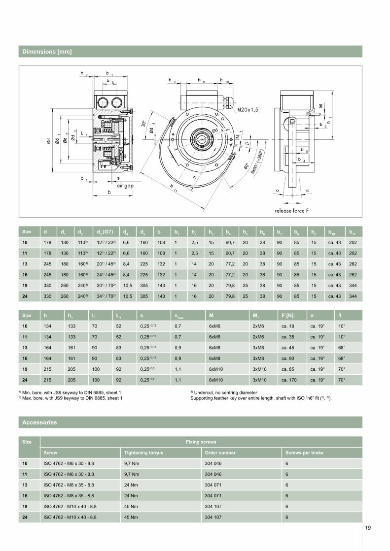
Size d d1 d2 d3 (G7) d4 d5 b b1 b2 b3 b4 b5 b6 b7 b8 b9 b10 b11
10 178 130 1103) 121) / 222) 6,6 160 108 1 2,5 15 60,7 20 38 90 85 15 ca. 43 202
11 178 130 1103) 121) / 222) 6,6 160 108 1 2,5 15 60,7 20 38 90 85 15 ca. 43 202
13 245 180 1603) 201) / 452) 8,4 225 132 1 14 20 77,2 20 38 90 85 15 ca. 43 262
16 245 180 1603) 241) / 452) 8,4 225 132 1 14 20 77,2 20 38 90 85 15 ca. 43 262
19 330 260 2403) 301) / 702) 10,5 305 143 1 16 20 79,8 25 38 90 85 15 ca. 43 344
24 330 260 2403) 341) / 702) 10,5 305 143 1 16 20 79,8 25 38 90 85 15 ca. 43 344
Size h h1 L L1 s smax M M1 F [N] α ß
10 134 133 70 52 0,25+0,12 0,7 6xM6 2xM6 ca. 18 ca. 19° 10°
11 134 133 70 52 0,25+0,12 0,7 6xM6 2xM6 ca. 35 ca. 19° 10°
13 164 161 90 83 0,25+0,15 0,9 6xM8 3xM8 ca. 45 ca. 19° 68°
16 164 161 90 83 0,25+0,15 0,9 6xM8 3xM8 ca. 90 ca. 19° 68°
19 215 205 100 92 0,25+0,2 1,1 6xM10 3xM10 ca. 85 ca. 19° 70°
24 215 205 100 92 0,25+0,2 1,1 6xM10 3xM10 ca. 170 ca. 19° 70°
1) Min. bore, with JS9 keyway to DIN 6885, sheet 12) Max. bore, with JS9 keyway to DIN 6885, sheet 1
3) Undercut, no centring diameterSupporting feather key over entire length, shaft with ISO “h6” fit (1), 2)).
Size Fixing screws
Screw Tightening torque Order number Screws per brake
10 ISO 4762 - M6 x 30 - 8.8 9,7 Nm 304 046 6
11 ISO 4762 - M6 x 30 - 8.8 9,7 Nm 304 046 6
13 ISO 4762 - M8 x 35 - 8.8 24 Nm 304 071 6
16 ISO 4762 - M8 x 35 - 8.8 24 Nm 304 071 6
19 ISO 4762 - M10 x 40 - 8.8 45 Nm 304 107 6
24 ISO 4762 - M10 x 40 - 8.8 45 Nm 304 107 6
Dimensions [mm]
Accessories
air gap
release force F
© KENDRION 16.11.2015
Kendrion (Villingen) GmbHWilhelm-Binder-Strasse 4-678048 Villingen-SchwenningenGermanyTel: +49 7721 877-0Fax: +49 7721 [email protected]


![EEX Line - europages.com · EEX Line Version 76 26E..B00 – DC ... Max. bore with fitting key JS9 as per DIN 6885, sheet 1 3) Undercut, ... Dimensions [mm]](https://static.documents.pub/doc/80x56/5b803f6b7f8b9ad4778d1b07/eex-line-eex-line-version-76-26eb00-dc-max-bore-with-fitting-key.jpg)


![Ppt eex[1]](https://static.documents.pub/doc/80x56/547b4f55b4af9fc9158b4e38/ppt-eex1.jpg)


