6.5.3.8 MBR Cleaning Operation The membranes require cleaning to maintain peak performance. There are two types of cleaning methods: maintenance cleans and recovery cleans. Maintenance cleans are scheduled through SCADA and are automatically initiated by the MBR system PLC as scheduled by the operator on a weekly basis. Recovery cleans are operator initiated and only are performed seasonally. There are two chemicals that can be used to clean the membranes. These chemicals are sodium hypochlorite and citric acid. The hypochlorite is used to remove organic contaminants from the membranes. The citric acid is used to remove inorganic contaminants from the membranes such as calcium carbonate, manganese and iron compounds. MBR Process Control Screens The MBR cleaning systems are controlled through SCADA by the MBR control system PLC located in the MBR building. The access to this control system is discussed in the following sections. The operator must access a number of screens to set up the cleaning cycles. The timers for each of the cleaning cycles are accessed through the plant setpoints screen. The maintenance clean schedule is accessed and set on the maintenance clean schedule screens for each of the individual MBR basins. A maintenance schedule can also be manually started on the MBR Process Main Screen The automatic operation of the MBR process is controlled through the SCADA system on the membrane main screen (Figure 6.5.3.81). The screen is accessed by clicking on the MBR. The screen is accessed by clicking on the MBR button <1> on the top of the screen.
Transcript
6.5.3.8 MBR Cleaning Operation
The membranes require cleaning to maintain peak performance. There are two types of cleaning methods: maintenance cleans and recovery cleans. Maintenance cleans are scheduled through SCADA and are automatically initiated by the MBR system PLC as scheduled by the operator on a weekly basis. Recovery cleans are operator initiated and only are performed seasonally.
There are two chemicals that can be used to clean the membranes. These chemicals are sodium hypochlorite and citric acid. The hypochlorite is used to remove organic contaminants from the membranes. The citric acid is used to remove inorganic contaminants from the membranes such as calcium carbonate, manganese and iron compounds.
MBR Process Control Screens The MBR cleaning systems are controlled through SCADA by the MBR control system PLC located in the MBR building. The access to this control system is discussed in the following sections. The operator must access a number of screens to set up the cleaning cycles. The timers for each of the cleaning cycles are accessed through the plant setpoints screen.
The maintenance clean schedule is accessed and set on the maintenance clean schedule screens for each of the individual MBR basins. A maintenance schedule can also be manually started on the
MBR Process Main Screen
The automatic operation of the MBR process is controlled through the SCADA system on the membrane main screen (Figure 6.5.3.8-‐1). The screen is accessed by clicking on the MBR. The screen is accessed by clicking on the MBR button <1> on the top of the screen.
Figure 6.5.3.8-‐1 – Membrane System Control Panel
MBR Cleaning Setpoint Entry
The MBR cleaning setpoints for both maintenance cleans and recovery cleans are set o through the plant setpoints menu. The plant setpoints menu is accessed from the MBR system main screen or any of the four MBR basin screens by clicking on the Plant Setpoints button <2> as shown in Figure 6.5.3.8-‐1. Clicking on this button provides a popup box with five input screen options as shown on the popup box as shown in Figure 6.5.3.8-‐2. These options are:
Clicking on each of these buttons puts up an input box to input the variables for each of these functions. Each of the input boxes is restricted to a specific range of values to ensure the values that are entered are appropriate.
1
2
2
Figure 6.5.3.8-‐2 – MBR Plant Setpoint Menu
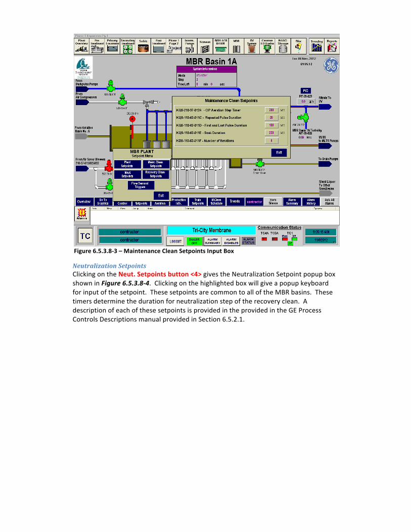
Maintenance Clean Setpoints Clicking on the Maintenance Clean Setpoints button <3> gives the Maintenance Clean Setpoint popup box shown in Figure 6.5.3.8-‐3. Clicking on the highlighted box will give a popup keyboard for input of the setpoint. These setpoints are common to all of the MBR basins. These timers determine the duration for each of the cleaning steps during maintenance clean. A description of each of these setpoints is provided in the provided in the GE Process Controls Descriptions manual provided in Section 6.5.2.1.
Neutralization Setpoints Clicking on the Neut. Setpoints button <4> gives the Neutralization Setpoint popup box shown in Figure 6.5.3.8-‐4. Clicking on the highlighted box will give a popup keyboard for input of the setpoint. These setpoints are common to all of the MBR basins. These timers determine the duration for neutralization step of the recovery clean. A description of each of these setpoints is provided in the provided in the GE Process Controls Descriptions manual provided in Section 6.5.2.1.
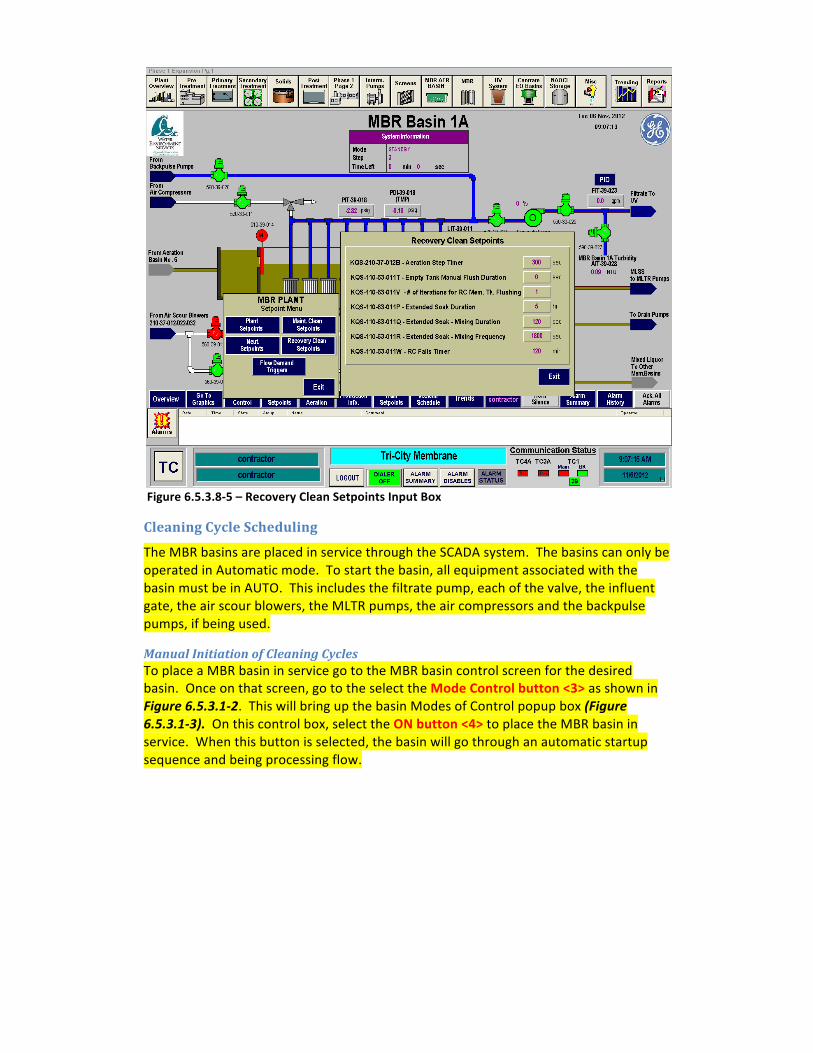
Recovery Clean Setpoints Clicking on the Recovery Clean Setpoints button <5> gives the Recovery Clean Setpoint popup box shown in Figure 6.5.3.8-‐5. Clicking on the highlighted box will give a popup keyboard for input of the setpoint. These setpoints are common to all of the MBR basins. These timers determine the duration for each step of the recovery clean. A description of each of these setpoints is provided in the provided in the GE Process Controls Descriptions manual provided in Section 6.5.2.1.
The MBR basins are placed in service through the SCADA system. The basins can only be operated in Automatic mode. To start the basin, all equipment associated with the basin must be in AUTO. This includes the filtrate pump, each of the valve, the influent gate, the air scour blowers, the MLTR pumps, the air compressors and the backpulse pumps, if being used.
Manual Initiation of Cleaning Cycles To place a MBR basin in service go to the MBR basin control screen for the desired basin. Once on that screen, go to the select the Mode Control button <3> as shown in Figure 6.5.3.1-‐2. This will bring up the basin Modes of Control popup box (Figure 6.5.3.1-‐3). On this control box, select the ON button <4> to place the MBR basin in service. When this button is selected, the basin will go through an automatic startup sequence and being processing flow.
Figure 6.5.3.1-‐3 – MBR Basin Modes of Operation Popup Box
Maintenance Clean Scheduling Clicking on the M.Clean Schedule button <14> located on the bottom of the MBR Basin screen (Figure 6.5.3.1-‐2) gives the Maintenance Clean Schedule popup box shown in Figure 6.5.3.1-‐15. This box is specific to each basin. This box provides for inputting the maintenance clean schedule for the basin. The maintenance clean scheduling provides for the operator to input the day of the week, time of day, the chemical to be used and the ability to enable or disable the specific day. On the screen shown in Figure 6.5.3.1-‐15, Basin 1A is scheduled for a hypochlorite maintenance clean on every Monday at 9:30 AM.
To place a MBR basin in service go to the MBR basin control screen for the desired basin. Once on that screen, go to the select the Mode Control button <3> as shown in Figure 6.5.3.1-‐2. This will bring up the basin Modes of Control popup box (Figure 6.5.3.1-‐3). On this control box, select the ON button <4> to place the MBR basin in service. When this button is selected, the basin will go through an automatic startup sequence and being processing flow.
Manual Initiations of Clean
Scheduled Maintenance Clean
Figure 6.5.3.1-‐3 – MBR Basin Modes of Operation Popup Box
Chemical Feed Pumps
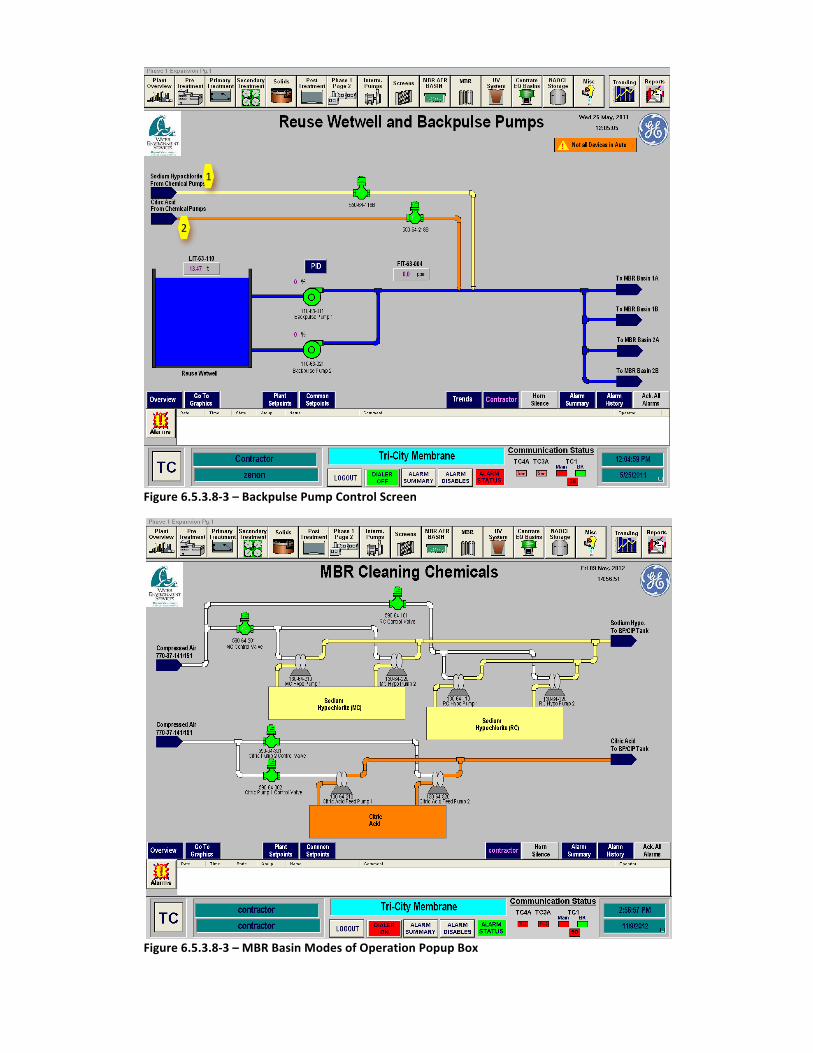
The control screen for the cleaning chemicals is acessed through the individual MBR Basin screens. The MBR Basin screen can be accessed by selecting the Backpulse Pump icon <2>.
The next step is to click on the one of the arrows for the chemical systems on the Backpulse Pump screen as shown in Figure 2. Clicking on the Sodium Hypochlorite From Chemical Pumps arrow will move to the Sodium Hypochlorite Screen and clicking on the Citric Acid From Chemical Pumps arrow will move to the Citric Acid Screen.
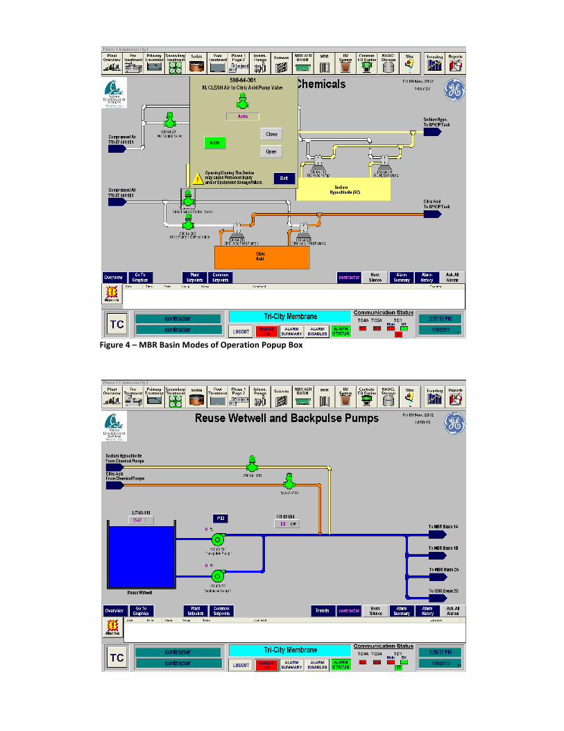
Citric Acid Feed System
3
Figure 6.5.3.8-‐3 – Backpulse Pump Control Screen
Figure 6.5.3.8-‐3 – MBR Basin Modes of Operation Popup Box
1
2
Figure 4 – MBR Basin Modes of Operation Popup Box
Figure 6.5.3.8-‐5 – MBR Basin Modes of Operation Popup Box
MBR Basin Startup Sequence To start up an MBR basin in Automatic Mode, follow the following sequence. This sequence is for a cold startup of the system. If the system is operating, confirmation that the equipment is off may not be necessary.
Step Action Location Confirm Equipment is in Off 1 Confirm Intermediate Pumps are OFF SCADA Main Screen
2 Confirm Fine Screen Influent and Effluent Gates are Closed
SCADA Main Screen
3 Confirm Fine Screens are in Off Position in SCADA SCADA Main Screen
4 Confirm Fine Screens are in OFF Position at Local Control Panel
Next to Fine Screens
5 Confirm Drum Screens are in Off Position in SCADA
SCADA Main Screen
6 Confirm Drum Screens are in Off Position at Local Control Panel
Fine Screen Electrical Room
Ready Equipment NOTE Confirm Aeration Basin influent gate is open AB#5 or AB#4 1 Close Breaker on MCC for Gates Fine Screen MCC 2 Close Breaker in MCC for Fine Screens Fine Screen MCC 3 Close Breaker in MCC for Drum Screens Fine Screen MCC
4 Select Fine Screen Channel to be placed into operation
5 Place Fine Screen Channel Influent Gate into Remote
Fine Screen Influent Channel
6 Place Fine Screen Channel Effluent Gate into Remote
Fine Screen EFfluent Channel
NOTE Confirm that a LOCK appears at above each gate on SCADA. This confirms both gates are open and will allow Intermediate Pumps to operate
7 Place Fine Screen in Remote at Local Control Panel
Next to Fine Screen
8 Confirm the sluice is directed to the desired Drum Screen by confirming the manual gate isolates the Drum Screen not to be used
Fine Screen Sluice Channel
9 Place Drum Screen in Remote at Local Control Panel
Fine Screen Building Electrical Room MCC
10 Place Fine Screen Channel Influent Gate Into AUTO
SCADA Fine Screen Control Screen
11 Place Fine Screen Channel Effluent Gate into AUTO
SCADA Fine Screen Control Screen
12 Place Drum Screen in AUTO SCADA Fine Screen Control Screen
13 Place Drum Screen Spray Valve in AUTO SCADA Fine Screen Control Screen