50
6.976 High Speed Communication Circuits and Systems Lecture 19 Basics of Wireless Communication Michael Perrott Massachusetts Institute of Technology Copyright © 2003 by Michael H. Perrott

6.976High Speed Communication Circuits and Systems
Lecture 19Basics of Wireless Communication
Michael PerrottMassachusetts Institute of Technology
Copyright © 2003 by Michael H. Perrott

M.H. Perrott MIT OCW
Amplitude Modulation (Transmitter)
Vary the amplitude of a sine wave at carrier frequency foaccording to a baseband modulation signalDC component of baseband modulation signal influences transmit signal and receiver possibilities- DC value greater than signal amplitude shown above
Allows simple envelope detector for receiverCreates spurious tone at carrier frequency (wasted power)
2cos(2πfot)
y(t)
Transmitter Output
x(t)0

M.H. Perrott MIT OCW
Impact of Zero DC Value
Envelope of modulated sine wave no longer corresponds directly to the baseband signal- Envelope instead follows the absolute value of the
baseband waveform- Envelope detector can no longer be used for receiver
The good news: less transmit power required for same transmitter SNR (compared to nonzero DC value)
2cos(2πfot)
y(t)
Transmitter Output
x(t)
0
M.H. Perrott MIT OCW
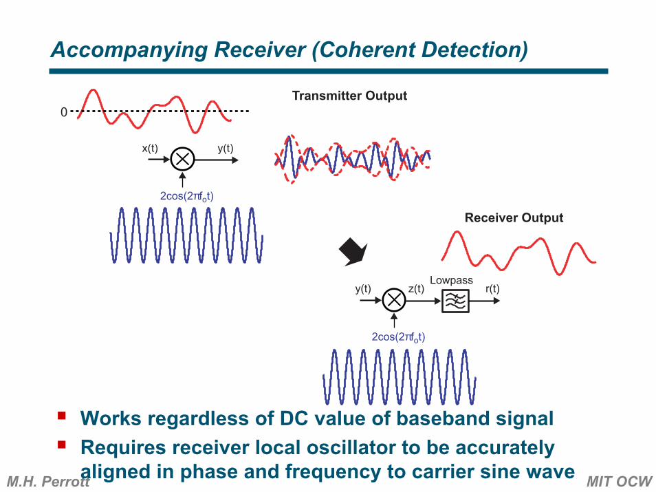
Accompanying Receiver (Coherent Detection)
Works regardless of DC value of baseband signalRequires receiver local oscillator to be accurately aligned in phase and frequency to carrier sine wave
2cos(2πfot)
y(t)
2cos(2πfot)
z(t)Lowpass
r(t)
Transmitter Output
Receiver Output
x(t)
y(t)
0

M.H. Perrott MIT OCW
Impact of Phase Misalignment in Receiver Local Oscillator
Worst case is when receiver LO and carrier frequency are phase shifted 90 degrees with respect to each other- Desired baseband signal is not recovered
2cos(2πfot)
y(t)
z(t)Lowpass
r(t)
Transmitter Output
Receiver Output
x(t)
y(t)
0
2sin(2πfot)

M.H. Perrott MIT OCW
Frequency Domain View of AM Transmitter
Baseband signal is assumed to have a nonzero DC component in above diagram- Causes impulse to appear at DC in baseband signal- Transmitter output has an impulse at the carrier frequency
For coherent detection, does not provide key information about information in baseband signal, and therefore is a waste of power
2cos(2πfot)
y(t)
Transmitter Output
x(t)
f-fo fo0
1 1
f
X(f)
0
avg(x(t))
f-fo fo0
Y(f)

M.H. Perrott MIT OCW
Impact of Having Zero DC Value for Baseband Signal
Impulse in DC portion of baseband signal is now gone- Transmitter output now is now free from having an
impulse at the carrier frequency (for ideal implementation)
2cos(2πfot)
y(t)
Transmitter Output
x(t)
f-fo fo0
1 1
f
X(f)
0
avg(x(t)) =0
f-fo fo0
Y(f)

M.H. Perrott MIT OCW
2cos(2πfot)
y(t)
Transmitter Output
x(t)
f-fo fo0
1 1
f
X(f)
0
f-fo fo0
Y(f)
2cos(2πfot)
z(t)Lowpass
r(t)
Receiver Output
y(t)
f-fo fo0
1 1
f-fo fo0
Z(f)
2fo-2fo
Lowpass
Frequency Domain View of AM Receiver (Coherent)

M.H. Perrott MIT OCW
Impact of 90 Degree Phase Misalignment
2cos(2πfot)
y(t)
Transmitter Output
x(t)
f-fo fo0
1 1
f
X(f)
0
f-fo fo0
Y(f)
2sin(2πfot)
z(t)Lowpass
r(t)
Receiver Output = 0
y(t)
f-fo fo0
Z(f)
2fo-2fo
Lowpass
f-f1
f10
j
-j

M.H. Perrott MIT OCW
Quadrature Modulation
Takes advantage of coherent receiver’s sensitivity to phase alignment with transmitter local oscillator- We essentially have two orthogonal transmission
channels (I and Q) available to us- Transmit two independent baseband signals (I and Q) onto two sine waves in quadrature at transmitter
Transmitter Outputf
-fo fo0
1 1
f0
f-f1
f10
j
-j
2cos(2πf2t)
2sin(2πf2t)
y(t)
it(t)
qt(t)
It(f)
Qt(f)
f0
f-fo fo0
1 11
1
f-fo
fo0
j
-j
Yi(f)
Yq(f)

M.H. Perrott MIT OCW
Accompanying Receiver
Demodulate using two sine waves in quadrature at receiver- Must align receiver LO signals in frequency and phase to
transmitter LO signalsProper alignment allows I and Q signals to be recovered as shown
Transmitter Outputf
-fo fo0
1 1
f0
Receiver Output
f-f1
f10
j
-j
2cos(2πf1t)
2sin(2πf1t)
y(t)
Lowpassir(t)
Lowpassqr(t)
2cos(2πf2t)
2sin(2πf2t)
y(t)
it(t)
qt(t)
It(f)
Qt(f)
f0
f-fo fo0
1 11
1
f-fo
fo0
j
-j
Yi(f)
Yq(f)
f-fo fo0
1 1
f-f1
f10
j
-j
f0
Ir(f)
Qr(f)
f0
2
2
M.H. Perrott MIT OCW
Impact of 90 Degree Phase Misalignment
I and Q channels are swapped at receiver if its LO signal is 90 degrees out of phase with transmitter- However, no information is lost!- Can use baseband signal processing to extract I/Q
signals despite phase offset between transmitter and receiver
Transmitter Outputf
-fo fo0
1 1
f0
Receiver Output
f-f1
f10
j
-j
2cos(2πf1t)
2sin(2πf1t)y(t)
ir(t)
qr(t)
2cos(2πf2t)
2sin(2πf2t)
y(t)
it(t)
qt(t)
It(f)
Qt(f)
f0
f-fo fo0
1 11
1
f-fo
fo0
j
-j
Yi(f)
Yq(f)
f-fo fo0
1 1
f-f1
f10
j
-j
f0
Ir(f)
Qr(f)
f0
2
2

M.H. Perrott MIT OCW
Simplified View
For discussion to follow, assume that - Transmitter and receiver phases are aligned- Lowpass filters in receiver are ideal- Transmit and receive I/Q signals are the same except for
scale factorIn reality- RF channel adds distortion, causes fading- Signal processing in baseband DSP used to correct
problems
f0
Receiver Output
2cos(2πf1t)2sin(2πf1t)
Lowpassir(t)
Lowpassqr(t)
it(t)
qt(t)
It(f)
Qt(f)
f0
1
1
f0
Ir(f)
Qr(f)
f0
2
2
2cos(2πf1t)2sin(2πf1t)
Baseband Input

M.H. Perrott MIT OCW
Analog Modulation
I/Q signals take on a continuous range of values (as viewed in the time domain)Used for AM/FM radios, television (non-HDTV), and the first cell phonesNewer systems typically employ digital modulation instead
Receiver Output
2cos(2πf1t)2sin(2πf1t)
Lowpassir(t)
Lowpassqr(t)
it(t)
qt(t)
2cos(2πf1t)2sin(2πf1t)
t
t
t
t
Baseband Input
M.H. Perrott MIT OCW
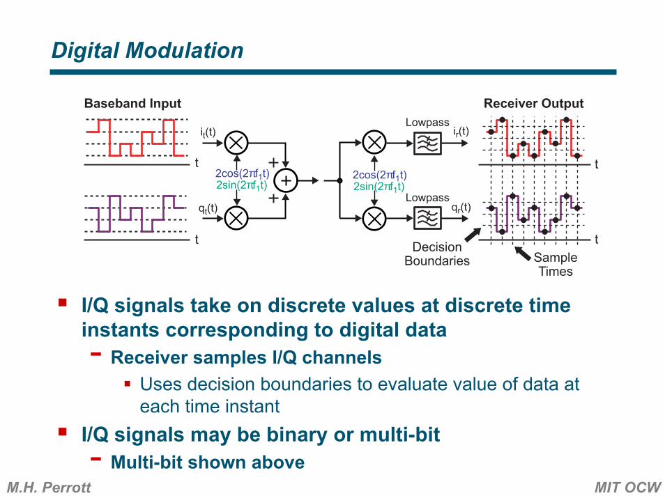
Digital Modulation
I/Q signals take on discrete values at discrete time instants corresponding to digital data- Receiver samples I/Q channels
Uses decision boundaries to evaluate value of data at each time instant
I/Q signals may be binary or multi-bit- Multi-bit shown above
Receiver Output
2cos(2πf1t)2sin(2πf1t)
Lowpassir(t)
Lowpassqr(t)
it(t)
qt(t)
2cos(2πf1t)2sin(2πf1t)
t
t
t
Baseband Input
tDecisionBoundaries Sample
Times
M.H. Perrott MIT OCW
Advantages of Digital Modulation
Allows information to be “packetized”- Can compress information in time and efficiently send
as packets through network- In contrast, analog modulation requires “circuit-
switched” connections that are continuously availableInefficient use of radio channel if there is “dead time” in information flow
Allows error correction to be achieved- Less sensitivity to radio channel imperfections
Enables compression of information- More efficient use of channel
Supports a wide variety of information content- Voice, text and email messages, video can all be
represented as digital bit streams

M.H. Perrott MIT OCW
Constellation Diagram
We can view I/Q values at sample instants on a two-dimensional coordinate systemDecision boundaries mark up regions corresponding to different data valuesGray coding used to minimize number of bit errors that occur if wrong decision is made due to noise
DecisionBoundaries I
Q
DecisionBoundaries
00 01 11 10
00
01
11
10

M.H. Perrott MIT OCW
Impact of Noise on Constellation Diagram
Sampled data values no longer land in exact same location across all sample instantsDecision boundaries remain fixedSignificant noise causes bit errors to be made
DecisionBoundaries I
Q
DecisionBoundaries
00 01 11 10
00
01
11
10

M.H. Perrott MIT OCW
Transition Behavior Between Constellation Points
Constellation diagrams provide us with a snapshot of I/Q signals at sample instantsTransition behavior between sample points depends on modulation scheme and transmit filter
DecisionBoundaries I
Q
DecisionBoundaries
00 01 11 10
00
01
11
10

M.H. Perrott MIT OCW
Choosing an Appropriate Transmit Filter
Transmit filter, p(t), convolved with data symbols that are viewed as impulses- Example so far: p(t) is a square pulse
Output spectrum of transmitter corresponds to square of transmit filter (assuming data has white spectrum)- Want good spectral efficiency (i.e. narrow spectrum)
tt
Td
t
|P(f)|2
f
data(t) p(t) x(t)
1/Td
Sdata(f)
f 00
*
f1/Td0
Sx(f)
Td

M.H. Perrott MIT OCW
Highest Spectral Efficiency with Brick-wall Lowpass
Use a sinc function for transmit filter- Corresponds to ideal lowpass in frequency domain
Issues- Nonrealizable in practice- Sampling offset causes significant intersymbol interference
tt
Td
t
|P(f)|2
f
data(t) p(t) x(t)
1/(2Td)
Sdata(f)
f 00
*
f1/(2Td)0
Sx(f)
Td0-Td

M.H. Perrott MIT OCW
Requirement for Transmit Filter to Avoid ISI
Time samples of transmit filter (spaced Td apart) must be nonzero at only one sample time instant- Sinc function satisfies this criterion if we have no offset
in the sample timesIntersymbol interference (ISI) occurs otherwiseExample: look at result of convolving p(t) with 4 impulses- With zero sampling offset, x(kTd) correspond to
associated impulse areas
t
p(t)
t
Td
data(t)
Td
* t
x(t)
Td
M.H. Perrott MIT OCW
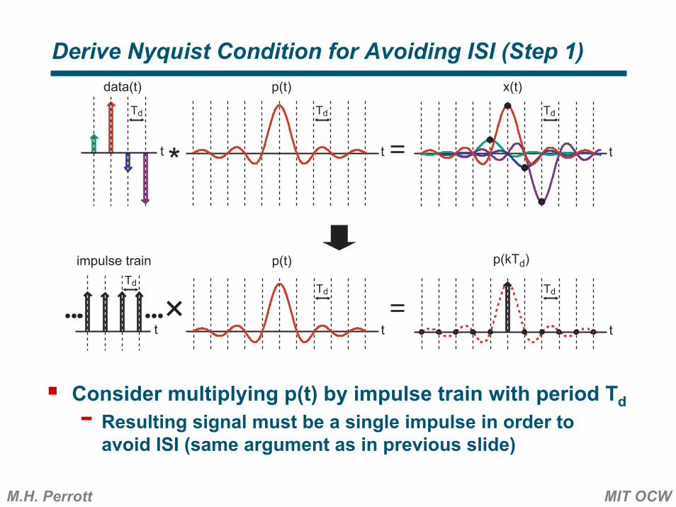
Derive Nyquist Condition for Avoiding ISI (Step 1)
Consider multiplying p(t) by impulse train with period Td- Resulting signal must be a single impulse in order to avoid ISI (same argument as in previous slide)
t
p(t)
t
Td
data(t)
Td
* t
x(t)
Td
t
p(t)
t
Td
impulse train
Td
t
p(kTd)
Td
M.H. Perrott MIT OCW
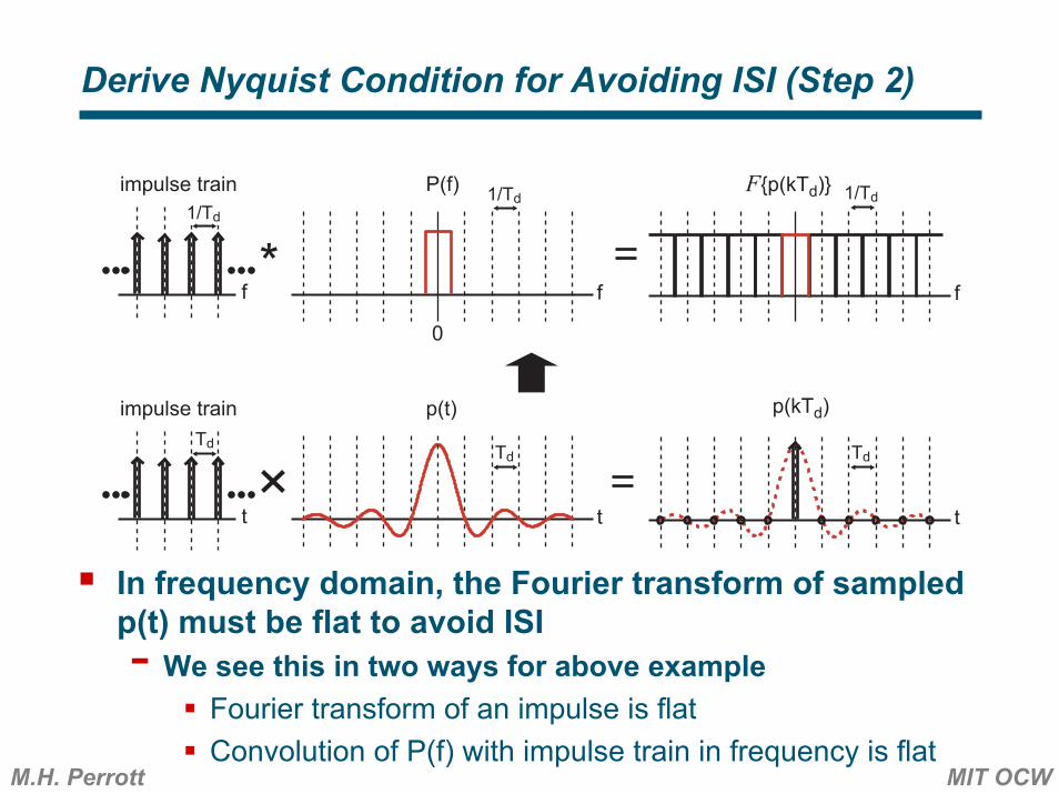
Derive Nyquist Condition for Avoiding ISI (Step 2)
In frequency domain, the Fourier transform of sampled p(t) must be flat to avoid ISI- We see this in two ways for above example
Fourier transform of an impulse is flatConvolution of P(f) with impulse train in frequency is flat
*
t
p(t)
t
Td
impulse train
Td
t
p(kTd)
Td
f
P(f)
f
impulse train
f
1/Td1/Td
1/Td
0
F{p(kTd)}

M.H. Perrott MIT OCW
A More Practical Transmit Filter
Transition band in frequency set by “rolloff” factor, α
Rolloff factor = 0: P(f) becomes a brick-wall filterRolloff factor = 1: P(f) looks nearly like a triangleRolloff factor = 0.5: shown above
t
p(t)
0 Td-Td
P(f)
0 1/Td-1/Tdf
2Td
1+α2Td
1-α
Raised-cosine filter is quite popular in many applications
M.H. Perrott MIT OCW
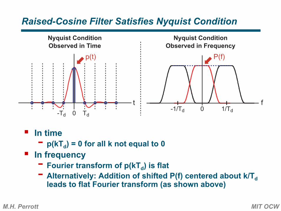
Raised-Cosine Filter Satisfies Nyquist Condition
In time- p(kTd) = 0 for all k not equal to 0In frequency- Fourier transform of p(kTd) is flat- Alternatively: Addition of shifted P(f) centered about k/Td
leads to flat Fourier transform (as shown above)
t
p(t)
0 Td-Td
P(f)
0 1/Td-1/Tdf
Nyquist ConditionObserved in Frequency
Nyquist ConditionObserved in Time

M.H. Perrott MIT OCW
Spectral Efficiency With Raised-Cosine Filter
More efficient than when p(t) is a square pulseLess efficient than brick-wall lowpass- But implementation is much more practical
Note: Raised-cosine P(f) often “split” between transmitter and receiver
tt
Td
t
|P(f)|2
f
data(t) p(t) x(t)
1/(2Td)
Sdata(f)
f 00
*
f1/(2Td)0
Sx(f)
Td0-Td

M.H. Perrott MIT OCW
Receiver Filter: ISI Versus Noise Performance
Conflicting requirements for receiver lowpass- Low bandwidth desirable to remove receiver noise and
to reject high frequency components of mixer output- High bandwidth desirable to minimize ISI at receiver
output
2cos(2πf1t)2sin(2πf1t)
Lowpassir(t)
Lowpassqr(t)
it(t)
qt(t)
2cos(2πf1t)2sin(2πf1t)
BasebandInput
f
f
It(t)
Qt(t)
Ir(t)
Qr(t)
ReceiverOutput
Raised-CosineFilter
M.H. Perrott MIT OCW
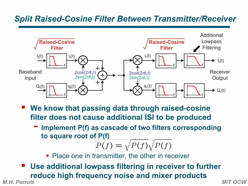
Split Raised-Cosine Filter Between Transmitter/Receiver
We know that passing data through raised-cosine filter does not cause additional ISI to be produced- Implement P(f) as cascade of two filters corresponding
to square root of P(f)
Place one in transmitter, the other in receiverUse additional lowpass filtering in receiver to further reduce high frequency noise and mixer products
f
2cos(2πf1t)2sin(2πf1t)
ir(t)
qr(t)
it(t)
qt(t)
2cos(2πf1t)2sin(2πf1t)
BasebandInput
f
f
It(t)
Qt(t)
Ir(t)
Qr(t)
f
f f
ReceiverOutput
Raised-CosineFilter
Raised-CosineFilter
AdditionalLowpassFiltering

Multiple Access Techniques

M.H. Perrott MIT OCW
The Issue of Multiple Access
Want to allow communication between many different usersFreespace spectrum is a shared resource- Must be partitioned between users
Can partition in either time, frequency, or through “orthogonal coding” (or nearly orthogonal coding) of data signals
M.H. Perrott MIT OCW
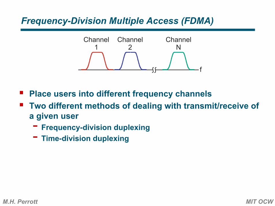
Frequency-Division Multiple Access (FDMA)
Place users into different frequency channelsTwo different methods of dealing with transmit/receive of a given user- Frequency-division duplexing- Time-division duplexing
f
Channel1
Channel2
ChannelN

M.H. Perrott MIT OCW
Frequency-Division Duplexing
Separate frequency channels into transmit and receive bandsAllows simultaneous transmission and reception- Isolation of receiver from transmitter achieved with duplexer- Cannot communicate directly between users, only between
handsets and base stationAdvantage: isolates usersDisadvantage: deplexer has high insertion loss (i.e. attenuates signals passing through it)
Transmitter RXTX
f
Duplexer Antenna
RX
TX
Receiver TransmitBand
ReceiveBand

M.H. Perrott MIT OCW
Time-Division Duplexing
Use any desired frequency channel for transmitter and receiverSend transmit and receive signals at different timesAllows communication directly between users (not necessarily desirable)Advantage: switch has low insertion loss relative to duplexerDisadvantage: receiver more sensitive to transmitted signals from other users
TransmitterSwitch Antenna
RX
TX
Receiver
switchcontrol

M.H. Perrott MIT OCW
Time-Division Multiple Access (TDMA)
Place users into different time slots- A given time slot repeats according to time frame period
Often combined with FDMA- Allows many users to occupy the same frequency
channel
t
Time Slot1
Time Slot2
Time SlotN
Time Slot1
Time SlotN
�Time Frame
M.H. Perrott MIT OCW
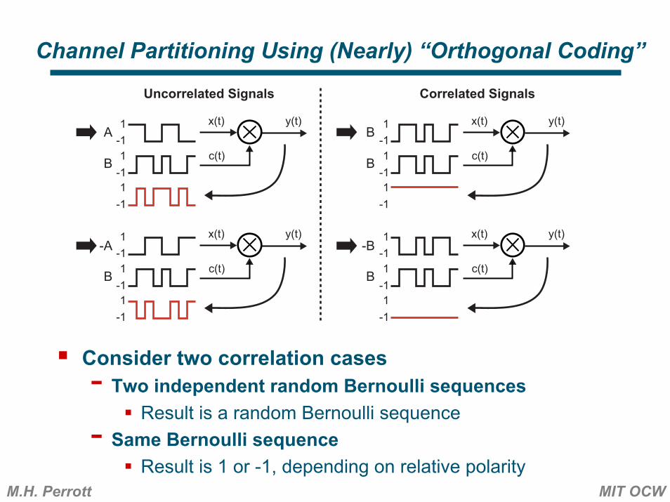
Channel Partitioning Using (Nearly) “Orthogonal Coding”
Consider two correlation cases- Two independent random Bernoulli sequences
Result is a random Bernoulli sequence- Same Bernoulli sequence
Result is 1 or -1, depending on relative polarity
y(t)x(t)
c(t)
1-11
-11
-1
y(t)x(t)
c(t)
1-11
-11
-1
y(t)x(t)
c(t)
1-11
-11
-1
y(t)x(t)
c(t)
1-11
-11
-1
A
-A
B
-B
B
B B
B
Uncorrelated Signals Correlated Signals

M.H. Perrott MIT OCW
Code-Division Multiple Access (CDMA)
Assign a unique code sequence to each transmitterData values are encoded in transmitter output stream by varying the polarity of the transmitter code sequence- Each pulse in data sequence has period Td
Individual pulses represent binary data values- Each pulse in code sequence has period Tc
Individual pulses are called “chips”
y1(t)x1(t)
PN1(t)
y2(t)x2(t)
PN2(t)
y(t)
SeparateTransmitters
Transmit SignalsCombine
in FreespaceTd
Tc

M.H. Perrott MIT OCW
Receiver Selects Desired Transmitter Through Its Code
Receiver correlates its input with desired transmitter code- Data from desired transmitter restored- Data from other transmitter(s) remains randomized
y1(t)x1(t)
PN1(t)
y2(t)x2(t)
PN2(t)
x(t) y(t)
SeparateTransmitters
Transmit SignalsCombine
in Freespace
Receiver(Desired Channel = 1)
PN1(t)
Lowpassr(t)

M.H. Perrott MIT OCW
Frequency Domain View of Chip Vs Data Sequences
Data and chip sequences operate on different time scales- Associated spectra have different width and height
tt
Tc
t
data(t) p(t) x(t)
Sdata(f)
f0
*1
-1Tc
1
-1
1
Sx(f)|P(f)|2
f1/Tc0
Tc
Td
1/Tdf1/Tc0
Tc
Td
1/Td
ttTd
t
data(t) p(t) x(t)
*1
-1
1
-1
1
Td

M.H. Perrott MIT OCW
Frequency Domain View of CDMA
CDMA transmitters broaden data spectra by encoding it onto chip sequencesCDMA receiver correlates with desired transmitter code- Spectra of desired channel reverts to its original width- Spectra of undesired channel remains broad
Can be “mostly” filtered out by lowpass
r(t)
Sy1(f)
f1/Tc0
Tc
Sx(f)
f1/Tc0
Tc
Td
1/Td
Sx1(f)
f0
Td
1/Td
Sy2(f)
f1/Tc0
Tc
Sx2(f)
f0
Td
1/Td
y1(t)x1(t)
PN1(t)
Transmitter 1
y2(t)x2(t)
PN2(t)
Transmitter 2y(t)
PN1(t)
Lowpass
Sx1(f)
Constant Envelope Modulation
M.H. Perrott MIT OCW
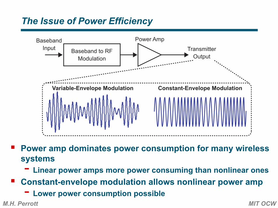
The Issue of Power Efficiency
Power amp dominates power consumption for many wireless systems- Linear power amps more power consuming than nonlinear ones
Constant-envelope modulation allows nonlinear power amp- Lower power consumption possible
Baseband to RFModulation
Power Amp
TransmitterOutput
BasebandInput
Variable-Envelope Modulation Constant-Envelope Modulation

M.H. Perrott MIT OCW
Simplified Implementation for Constant-Envelope
Constant-envelope modulation limited to phase and frequency modulation methodsCan achieve both phase and frequency modulation with ideal VCO- Use as model for analysis purposes- Note: phase modulation nearly impossible with practical VCO
Baseband to RF Modulation Power Amp
TransmitterOutput
BasebandInput
Constant-Envelope Modulation
TransmitFilter
M.H. Perrott MIT OCW
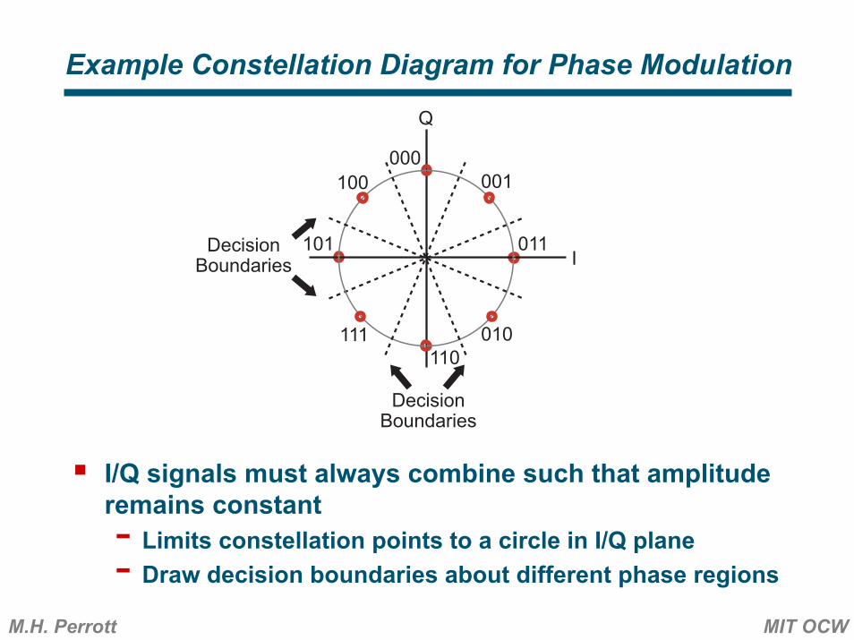
Example Constellation Diagram for Phase Modulation
I/Q signals must always combine such that amplitude remains constant- Limits constellation points to a circle in I/Q plane- Draw decision boundaries about different phase regions
DecisionBoundaries I
Q
DecisionBoundaries
000001
011
110111
100
101
010
M.H. Perrott MIT OCW
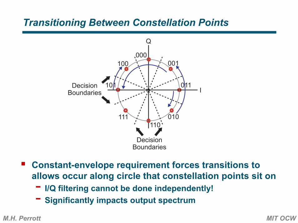
Transitioning Between Constellation Points
Constant-envelope requirement forces transitions to allows occur along circle that constellation points sit on- I/Q filtering cannot be done independently!- Significantly impacts output spectrum
DecisionBoundaries I
Q
DecisionBoundaries
000001
011
110111
100
101
010
M.H. Perrott MIT OCW
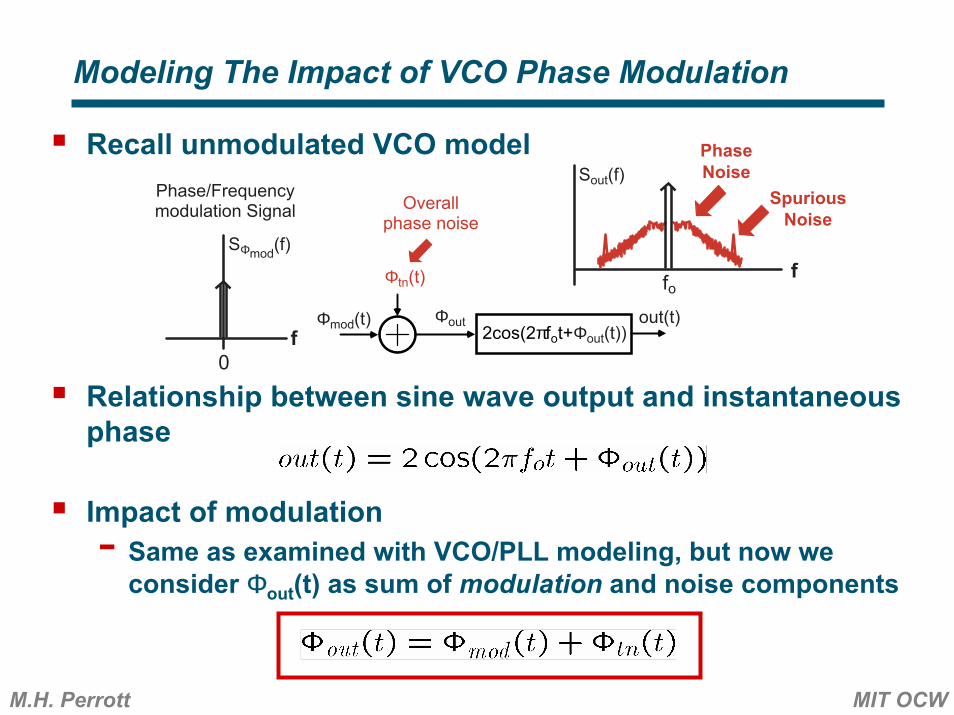
Recall unmodulated VCO model
Relationship between sine wave output and instantaneous phase
Impact of modulation- Same as examined with VCO/PLL modeling, but now we
consider Φout(t) as sum of modulation and noise components
Modeling The Impact of VCO Phase Modulation
Φmod(t)
Φtn(t)
Phase/Frequencymodulation Signal
f
PhaseNoise
fo
Sout(f)Overall
phase noise
Φout2cos(2πfot+Φout(t))
out(t)f
0
SΦmod(f)
SpuriousNoise

M.H. Perrott MIT OCW
Relationship Between Sine Wave Output and its Phase
Key relationship (note we have dropped the factor of 2)
Using a familiar trigonometric identity
Approximation given |Φtn(t)| << 1

M.H. Perrott MIT OCW
Relationship Between Output and Phase Spectra
Approximation from previous slide
Autocorrelation (assume modulation signal independent of noise)
Output spectral density (Fourier transform of autocorrelation)
- Where * represents convolution and

M.H. Perrott MIT OCW
Impact of Phase Modulation on the Output Spectrum
Spectrum of output is distorted compared to SΦmod(f)Spurs converted to phase noise
Φmod(t)
Φtn(t)
Phase/Frequencymodulation Signal
f
PhaseNoise
fo
Sout(f)Overall
phase noise
Φout2cos(2πfot+Φout(t))
out(t)f
0
SΦmod(f)
SpuriousNoise
Φmod(t)
Φtn(t)
Phase/Frequencymodulation Signal
ffo
Sout(f)Overall
phase noise
Φout2cos(2πfot+Φout(t))
out(t)f
0
SΦmod(f)
M.H. Perrott MIT OCW
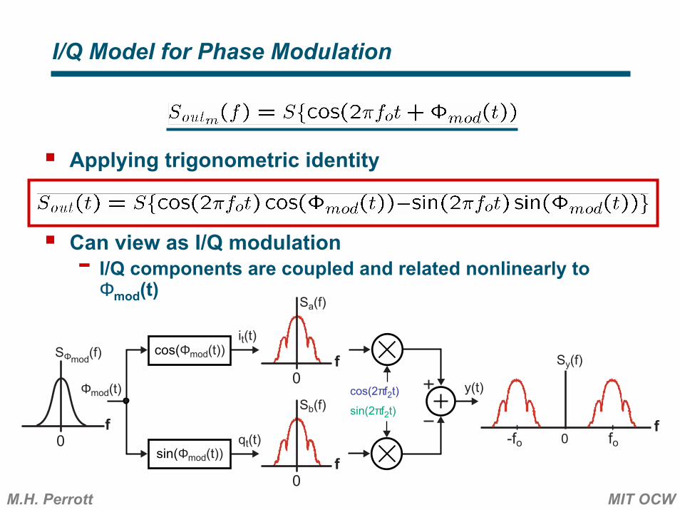
I/Q Model for Phase Modulation
Applying trigonometric identity
Can view as I/Q modulation- I/Q components are coupled and related nonlinearly to Φmod(t)
f0
SΦmod(f)
cos(2πf2t)
sin(2πf2t)
y(t)
-fo fo0
cos(Φmod(t))
sin(Φmod(t))
f0
Sa(f)
Sy(f)
it(t)
qt(t)
f0
Sb(f)f
Φmod(t)


![6.976 High Speed Communication Circuits and …...Charge Pump N sd[m] ref(t) out(t)e(t) div(t) Σ−∆ Modulator v(t) N[m] Loop Filter Divider VCO Focus on this architecture since](https://static.documents.pub/doc/80x56/5f084f357e708231d4215f82/6976-high-speed-communication-circuits-and-charge-pump-n-sdm-reft-outtet.jpg)


