Technical Services Report Complete Page 26 of 48 7. CORE INFUSION 7.1 Manufacture of a Sandwich Laminate a Single Infusion One of the prominent advantages of resin infusion is that where a sandwich laminate is required, the core can be infused at the same time as the skins of the laminate. This can reduce processing time dramatically in many components. Infusion of a full sandwich component in one hit requires considerably more preparation than that of a simple single skin infusion, but this can be easily recouped once a successful infusion has been completed and no further work is required to manufacture a full sandwich laminate. A fully infused sandwich laminate can also be lighter than any most other manufacturing systems as the core bond used is exactly the right amount – the vacuum pressure denotes that the core will use exactly the right amount of resin to infuse a panel and fill the grooves and patterns between the core and the first plies. To aid infusion for sandwich construction, core can be modified to allow resin to flow more easily. A key parameter for succeeding in a cored infusion is allowing resin flow between the two plies of laminate. This can be done in many ways, and most cores can be bought in a variety of “infusion friendly” designs with features such as drilled holes, scored lines, grooves and scrims on each side or a combination of these. The various types are available to allow flexibility in the speed and flow of the resin – some cores can infuse very quickly and others can reduce the flow to allow thicker laminates to be infused. It is very important to note that if a slow transfer mesh is used, the resin may use the core as the path of least resistance, meaning the mesh is made redundant. Figure 8 - Examples of Infusion Core
Transcript
Technical Services Report
Complete Page 26 of 48
7. CORE INFUSION
7.1 Manufacture of a Sandwich Laminate a Single Infusion
One of the prominent advantages of resin infusion is that where a sandwich laminate is required, the core
can be infused at the same time as the skins of the laminate. This can reduce processing time dramatically
in many components. Infusion of a full sandwich component in one hit requires considerably more
preparation than that of a simple single skin infusion, but this can be easily recouped once a successful
infusion has been completed and no further work is required to manufacture a full sandwich laminate.
A fully infused sandwich laminate can also be lighter than any most other manufacturing systems as the core
bond used is exactly the right amount – the vacuum pressure denotes that the core will use exactly the right
amount of resin to infuse a panel and fill the grooves and patterns between the core and the first plies.
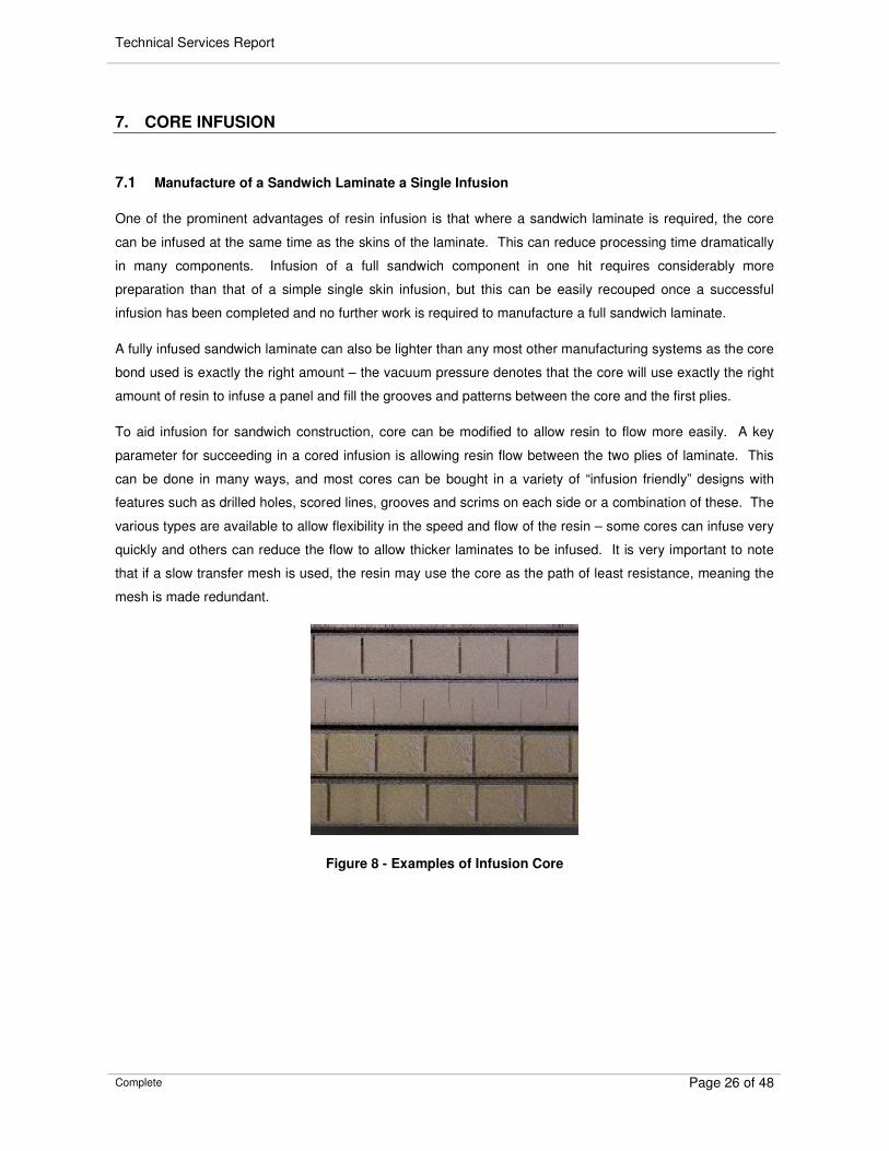
To aid infusion for sandwich construction, core can be modified to allow resin to flow more easily. A key
parameter for succeeding in a cored infusion is allowing resin flow between the two plies of laminate. This
can be done in many ways, and most cores can be bought in a variety of “infusion friendly” designs with
features such as drilled holes, scored lines, grooves and scrims on each side or a combination of these. The
various types are available to allow flexibility in the speed and flow of the resin – some cores can infuse very
quickly and others can reduce the flow to allow thicker laminates to be infused. It is very important to note
that if a slow transfer mesh is used, the resin may use the core as the path of least resistance, meaning the
mesh is made redundant.
Figure 8 - Examples of Infusion Core
Technical Services Report
Complete Page 27 of 48
8. TRANSFER MEDIUM
The transfer medium is used in infusion to distribute resin from the feed lines over the laminate. The feed
lines carry the resin around the part, where it then distributes through the mesh to the laminate.
8.1 Transfer Mesh
Transfer mesh is the most common system used for distribution of resin around a part. It is a very
permeable, open fabric that is placed in the bag with the laminate allowing the resin to flow through it and
around the component. Mesh types have developed which allow variable flow rates and directional flow,
allowing quicker infusions and more control on flow direction.
Woven textile mesh has been developed from through the advanced textiles industry to give reliable and
repeatable mesh, with close tolerances on thickness and uniformity, and therefore permeability. These
meshes are available in a variety of thickness and types, which can offer uniform flow or directionally biased
flow for parts where the infusion is required to be slowed or accelerated. Mesh is generally used on the
surface of the part, after the peel ply to allow it to be completely removed once the infused part has cured. In
some cases, the mesh can be built into the laminate stack without too much reduction in the mechanical
properties of the laminate.
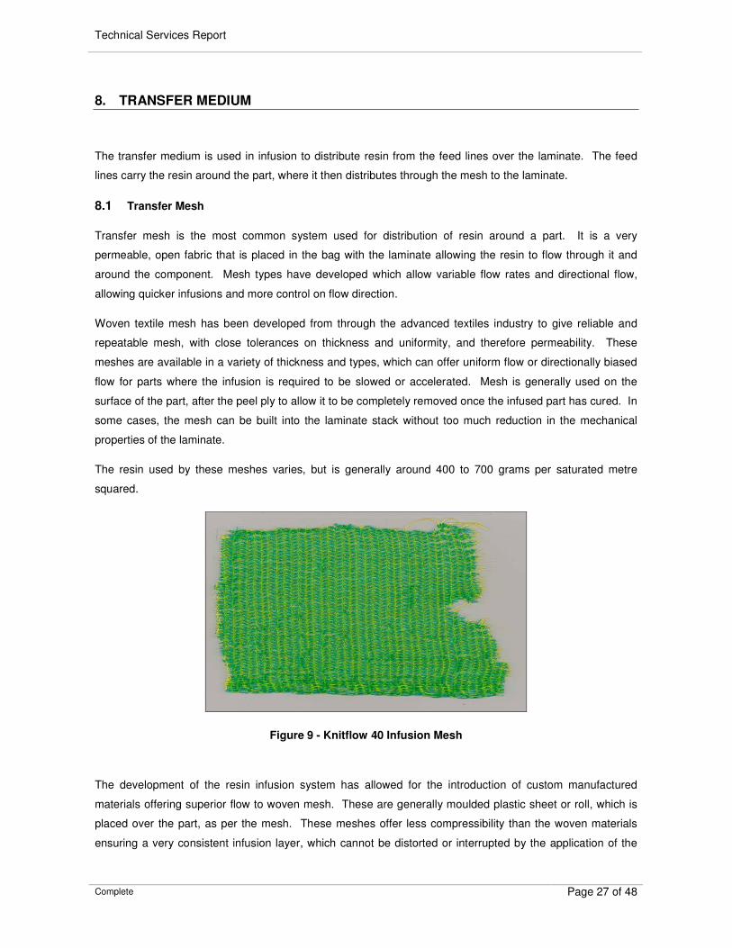
The resin used by these meshes varies, but is generally around 400 to 700 grams per saturated metre
squared.
Figure 9 - Knitflow 40 Infusion Mesh
The development of the resin infusion system has allowed for the introduction of custom manufactured
materials offering superior flow to woven mesh. These are generally moulded plastic sheet or roll, which is
placed over the part, as per the mesh. These meshes offer less compressibility than the woven materials
ensuring a very consistent infusion layer, which cannot be distorted or interrupted by the application of the
Technical Services Report
Complete Page 28 of 48
vacuum. It does, however require considerably more tailoring to achieve a good result on complex
components where the drape of the moulded materials is very much lower.
Different mesh types have different permeability’s according to some of the factors covered above;
thickness, weave and size of fibres etc. These will all have an impact on the speed of the mesh and the
amount of resin that is allowed to flow through it during the infusion. This is an important factor for
calculating the infusion resin gel time, the amount of resin required at different stages of the infusion and the
Overlaps in mesh can create routes for resin to “racetrack” along, allowing it to miss sections of the laminate.
To avoid this, it is advisable to keep mesh overlaps as small as possible, but they should always be below
30mm.
8.2 Transfer Core
If core is being used over a majority of the infused component, it can be possible to this material to transfer
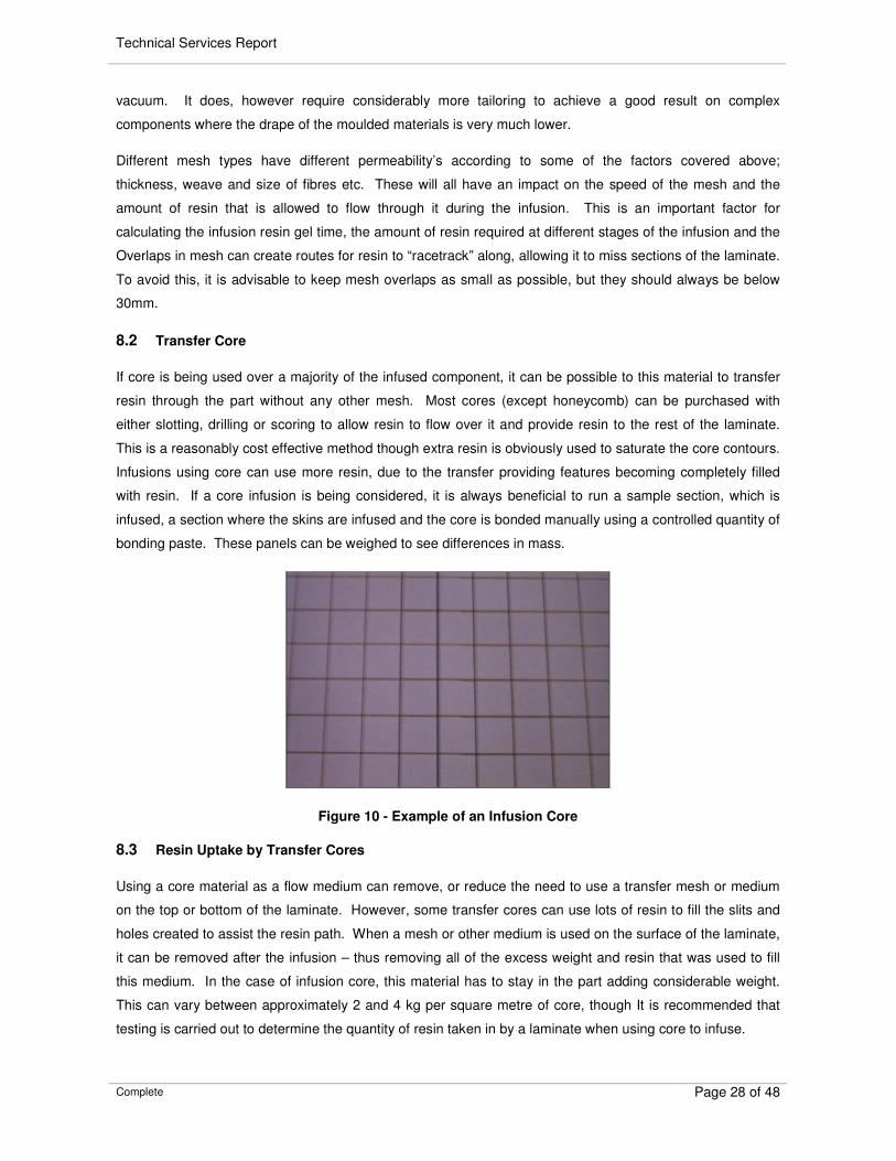
resin through the part without any other mesh. Most cores (except honeycomb) can be purchased with
either slotting, drilling or scoring to allow resin to flow over it and provide resin to the rest of the laminate.
This is a reasonably cost effective method though extra resin is obviously used to saturate the core contours.
Infusions using core can use more resin, due to the transfer providing features becoming completely filled
with resin. If a core infusion is being considered, it is always beneficial to run a sample section, which is
infused, a section where the skins are infused and the core is bonded manually using a controlled quantity of
bonding paste. These panels can be weighed to see differences in mass.
Figure 10 - Example of an Infusion Core
8.3 Resin Uptake by Transfer Cores
Using a core material as a flow medium can remove, or reduce the need to use a transfer mesh or medium
on the top or bottom of the laminate. However, some transfer cores can use lots of resin to fill the slits and
holes created to assist the resin path. When a mesh or other medium is used on the surface of the laminate,
it can be removed after the infusion – thus removing all of the excess weight and resin that was used to fill
this medium. In the case of infusion core, this material has to stay in the part adding considerable weight.
This can vary between approximately 2 and 4 kg per square metre of core, though It is recommended that
testing is carried out to determine the quantity of resin taken in by a laminate when using core to infuse.
Technical Services Report
Complete Page 29 of 48
9. RESIN FEED
9.1 Definitions
There are a variety of piping types used in resin infusion – these are best designated as:
� Feed Pipe – The pipe running from the resin bucket to the part where resin flow into the part is
controlled
� Resin Distribution Pipe – The pipes that supply resin around the part – these are generally drilled or
cut to provide an even feed along the part.
9.2 Feed Pipe
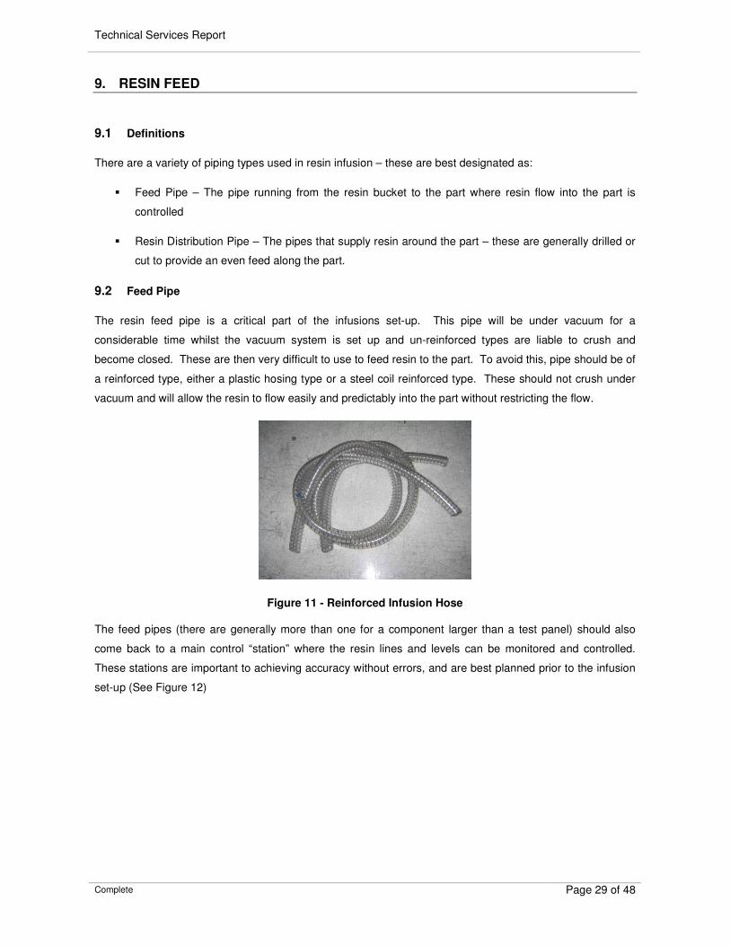
The resin feed pipe is a critical part of the infusions set-up. This pipe will be under vacuum for a
considerable time whilst the vacuum system is set up and un-reinforced types are liable to crush and
become closed. These are then very difficult to use to feed resin to the part. To avoid this, pipe should be of
a reinforced type, either a plastic hosing type or a steel coil reinforced type. These should not crush under
vacuum and will allow the resin to flow easily and predictably into the part without restricting the flow.
Figure 11 - Reinforced Infusion Hose
The feed pipes (there are generally more than one for a component larger than a test panel) should also
come back to a main control “station” where the resin lines and levels can be monitored and controlled.
These stations are important to achieving accuracy without errors, and are best planned prior to the infusion
set-up (See Figure 12)
Technical Services Report
Complete Page 30 of 48
Figure 12 - Typical Infusion Feed Pipe Layout
9.3 Feed Distribution Pipe
The feed distribution pipe is used to supply resin around the part to aid the infusion. This is not always a
pipe as other methods are available, but is most common. A typical infusion pipe is made using spiral
binding coil, as used for holding cables and wires together. This is cheap, excellent for flow and is available
in a variety of sizes. It does require some preparation, as it should be pre-stretched before it is laid onto the
part to assist resin feeding onto the infusion mesh.
Figure 13 - Infusion Feed Pipe
9.4 Feed Distribution Pipe Length
There is a limit to the length of infusion feed distribution pipe. Beyond this point, the friction of the resin in
the pipe, and the spread of the resin nearer the inlet into the part mean that the flow is severely hindered and
in some cases stopped completely until there is sufficient resin to continue (and the pressure has equalised
throughout the feed pipe. However, this is not a situation that should be attempted for an infusion, as it
increases the risk of a failed part considerably. It is perfectly possible to have more than one resin inlet on a
feed line for long parts. This should allow the infusion of very long parts in a shorter time.
Technical Services Report
Complete Page 31 of 48
9.5 Feed Distribution Pipe Size
Resin feed pipes can vary depending on the size of part being infused. It is important that the feed hose is
large enough to allow plenty of resin into the part, yet not too large that excess resin is used just filling the
pipes, or the resin is able to run out of the inlet pipe far too quickly.
Some approximate dimensions:
Size of Infusion Resin Distribution
Pipe Size
Resin (g) Contained in 1 Metre Length
Small Component (0.2m x 0.2m) <5mm ID1 <23
Medium Component (1m x 1m) >8mm ID <60
Large Component (5m x 5m) >10mm ID <94
Very Large Component (10m x 10m) >14mm ID <185
Very Long, Multi-Inlet Feed >18mm ID <305
Table 3 - Infusion Feed Pipe Sizing
9.6 Resin Feed Pipe Attachment
Resin feed pipe can be attached to the mesh using a variety of methods. The simplest for small components
is to use masking tape bands every 500mm and where there are defined details to hold the lines in place.
For larger infusions or very complex details, cotton thread or string can be used. This can be tied through
the mesh to hold it in place using a bent needle. This has an advantage of not snagging or grabbing the
vacuum bag when it is placed over, as can happen with sticky tapes.
9.7 Resin Feed Pipe Termination
Feed pipe terminations vary according to inlet type. If the inlet type is of the solid type where the spiral feed
hose is placed directly on the surface of the part being infused, then the termination can simply be the end of
the spiral tube. It is recommended that to prevent the ends of spiral infusion hoses puncturing the vacuum
bag that either a small square of breather fabric is taped in place, or that a piece of masking tape is placed
over the end.
In infusion designs where the quality of the infused part surface is critical and infusion feed lines are in pleats
in the vacuum bag. It is easy to finish the pipe as this will be away from the part and the vacuum bag will
already be closely wrapped (yet not able to puncture in most cases)
1 Internal Diameter of the Spiral Feed Distribution Pipe
Technical Services Report
Complete Page 32 of 48
9.8 Resin Feed Pipe Mounting
Resin feed pipes can be mounted in a number of ways to provide different results. If the feed pipes are
placed directly on the surface of the mesh they are liable to print through to the laminate below.
Figure 14 - Infusion Feed Pipe Print on Laminate
If the infused component is not required to give a surface finish such as on the back face of a thick tooling
skin, this printing may not be a problem and placing the infusion piping directly onto the mesh surface can
save a lot of time. If an unprinted finish is required, then another approach should be taken which involves
placing the resin feed lines in pleats in the vacuum bag.
Figure 15 - Infusion Feed Pipe in Vacuum Bag Pleat
This system can remove the printing on the surface of the laminate and allow easier removal of the feed
pipes. This system does have some drawbacks - the flow of the resin is reduced considerably as the resin
is restricted by the thickness of the mesh from the feed pipe to the component. The feed pipe is wrapped
placed at the bottom of a separate section of transfer mesh, which is doubled over and then shaped to form
a connection to the main infusion mesh.
Technical Services Report
Complete Page 33 of 48
10. VACUUM
The Vacuum is the backbone to the entire system and requires careful planning to ensure that it remains
operational and effective throughout the infusion.
10.1 Measurement of Vacuum
It is important to define what is meant by vacuum and how it is measured in this circumstance. Vacuum can
be quoted in many ways – as a pressure, as a negative from the absolute or as a positive as a vacuum
reading, not a pressure reading.
The world is under a constant pressure, referred to as Atmospheric Air Pressure. The pressure on various
parts of the planet changes continually, generally in a range where 970mbar (Millibar) is what would be
called “low pressure” and 1030mbar would be “high pressure”. On this scale, our ultimate vacuum would be
0mbar, where there is no remaining pressure (all air has been removed)
There is often confusion over vacuum where a “high” vacuum is a low pressure, or visa versa and many
other combinations. It is apparent that the following levels could be quoted where atmospheric is 1000mbar
and 98% vacuum has been achieved;
o 20mbar vacuum (The remaining “pressure”, or “absolute pressure” in the bag)
o 980mbar vacuum (The “removed” pressure)
o –980mbar (A relative pressure to atmospheric)
o “Nearly full vacuum” (Relative to Atmospheric pressure)
o “High Vacuum” (IE, High Percentage Vacuum and Low Absolute Pressure)
This indicates some of the areas where confusion can occur. To confuse this issue further, there are also
many different units in use for vacuum. One millibar is one thousandth of a bar pressure, and one bar
pressure is 29.56 Inches of Mercury. This guide is based around mbar units, as this is the most accurate
method of testing and measuring vacuum.
Where Infusion is involved, the following measures of vacuum are generally most common:
o Atmospheric pressure is measured in mbar, and quoted such as “1021mbar Atmospheric”
o When a part is placed under vacuum the pressure is dropping, and vacuum level is increasing, and
0mbar is a full atmosphere of vacuum.
o An achievable and realistic quote for a vacuum level in a vacuum bag would be “34.8mbar”, and
when this is leaking it is losing vacuum
10.2 Systems
Technical Services Report
Complete Page 34 of 48
The vacuum system required for an infusion would probably be the same as one used for vacuum bag work,
if this has been done previously. Although it will not be important for smaller jobs, on larger infusions the
ultimate vacuum should be as low as possible – pumps are generally rated on two-performance criteria
capacity (or amount of air removed per hour), and ultimate vacuum level. This has a range from 950mbar to
999.8-mbar Vacuum, dependent on specification. For infusion, a pump capable of 950mbar is more than
sufficient for simple and flat components, and above 980mbar should produce more complex items, though if
a variety of applications and component types are being infused, the vacuum system should be capable of
995mbar and above.
10.3 Resin Traps
It is vital to place a defence system in the infusion to stop excess resin running from the part flowing into the
vacuum system and especially the vacuum pump. In most cases, this is done using a resin trap unit, which
acts as a filter – allowing application of vacuum but stopping resin from running towards the pump.
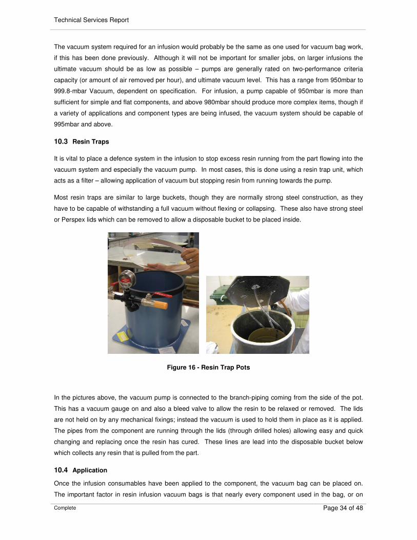
Most resin traps are similar to large buckets, though they are normally strong steel construction, as they
have to be capable of withstanding a full vacuum without flexing or collapsing. These also have strong steel
or Perspex lids which can be removed to allow a disposable bucket to be placed inside.
Figure 16 - Resin Trap Pots
In the pictures above, the vacuum pump is connected to the branch-piping coming from the side of the pot.
This has a vacuum gauge on and also a bleed valve to allow the resin to be relaxed or removed. The lids
are not held on by any mechanical fixings; instead the vacuum is used to hold them in place as it is applied.
The pipes from the component are running through the lids (through drilled holes) allowing easy and quick
changing and replacing once the resin has cured. These lines are lead into the disposable bucket below
which collects any resin that is pulled from the part.
10.4 Application
Once the infusion consumables have been applied to the component, the vacuum bag can be placed on.
The important factor in resin infusion vacuum bags is that nearly every component used in the bag, or on
Technical Services Report
Complete Page 35 of 48
vacuum control is perished – so it important that breach units, vacuum gauges etc are not used. Once the
bag is complete, the vacuum should be applied slowly up to the point where the bag begins to stick to the
laminate – but is still very loose. The vacuum level should be fixed at this point if possible to allow the bag to
be tailored and fitted as much as possible before the level is slowly increased. It is absolutely vital that there
is no bridging anywhere on the part – this will create a virtual river for resin to run along, possibly ruining the
infusion. If this is not the case, bridging in the part will create a solid resin cast of the bag, possible causing
exotherm problems and also increasing shrinkage locally, causing distortion.
10.5 Vacuum Bag Defects
Quality vacuum bag is manufactured in a near sterile environment, so holes and perforations should not
have been introduced to the film by contaminants. However, no vacuum bag is guaranteed to contain no
holes or imperfections, so this should always be considered when an infusion is being prepared. It is
obviously critical that vacuum bag is left on a covered roll until it is required, and then should be distributed
carefully on the part at the latest time allowed, reducing the time for it to be affected by sharp objects. If joins
are required in the bag, it is also advisable that these are done off the part to avoid any snagging or potential
tearing that may occur. For best guarantees of quality vacuum bag, obtain material which is approved, or
manufactured especially for
It is also very important that vacuum bags are stored to manufacturer’s specifications. Conditions such as
low humidity can make bags brittle and more likely to tear and leak.
10.6 Vacuum Bag Bridging
Vacuum bag bridging should be removed during the vacuum bagging process, but it is difficult to see some
bridges and therefore some may still be present when the component is infused. A vacuum bag bridge will
allow resin an easy path where it can move past the laminate, which offers greater resistance. If the bridging
is only small and does not lead to a vacuum outlet hose, the problem may resolve itself by filling from around
the area that is bridged.
Figure 17 - A Bridge in an Infusion Bag
Figure 17 shows a how a bridge in a vacuum bag has allowed resin to “racetrack” down the component
ahead of the main flow front. In this case, the resin will still continue to fill, as the ridge in the laminate is the
Technical Services Report
Complete Page 36 of 48
end of the bridge. This situation could have been avoided by careful inspection of the bag in this area before
the infusion began.
10.7 Fibre Settling
The repeat application of the vacuum on the dry fibres can cause them to settle and nest together. Whilst it
is recommended that a vacuum system is cycled a few times during the vacuum bag application and testing,
it is also important that the vacuum is not cycled too many times as each cycle will nest the fibres further,
which reduces the permeability and can reduce the infusion capability and increase the infusion time.
10.8 Vacuum Drop Test
The vacuum drop test is a vital check for resin infusion. A vacuum pump will be capable of moving a
considerable amount of air from the part, and this may therefore override the effects of any leaks. This will
give a vacuum gauge on the part that shows full vacuum indicating that vacuum levels in the part are
acceptable. However, this is not the case.
Resin infusion relies on vacuum integrity, not level. The level of the vacuum is almost irrelevant if the
integrity is not 100%. The method of checking the integrity of an infusion component is to perform a vacuum
drop test. This system shows the amount of vacuum being lost in the part through leaks and is the key
number to the success of the infusion.
To perform a vacuum drop test, the component should be placed under full vacuum and any leaks or
obvious air paths closed. A vacuum-monitoring gauge should be placed in the infusion line or in the system
to allow the component vacuum level to be read. The vacuum should then be shut off using a valve, to
isolate the component from the pump. The level of vacuum should then be recorded to ascertain the loss of
vacuum. As a general target, a very good infusion will require a loss no greater than 5mBar in 5 minutes
from when the vacuum was switched off. It is not recommended to carry out an infusion with a loss any
greater than 50mBar in five minutes, as this is quite a significant drop and the quality of the finished
component will be at risk.
The tables below show two vacuum drop test recordings, one for a very good component, and one for a tool
requiring further work to improve the integrity:
Time (Mins) Vacuum Level
0 985.3
1 984.8
2 984.2
3 983.8
4 983.4
5 982.9
Total Vacuum Drop 2.4 mbar
Table 4 - Example of an Acceptable Vacuum Drop Test
Technical Services Report
Complete Page 37 of 48
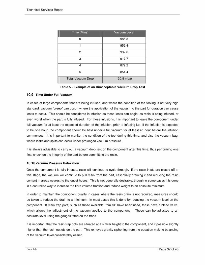
Time (Mins) Vacuum Level
0 985.3
1 952.4
2 932.6
3 917.7
4 879.2
5 854.4
Total Vacuum Drop 130.9 mbar
Table 5 - Example of an Unacceptable Vacuum Drop Test
10.9 Time Under Full Vacuum
In cases of large components that are being infused, and where the condition of the tooling is not very high
standard, vacuum “creep” can occur, where the application of the vacuum to the part for duration can cause
leaks to occur. This should be considered in infusion as these leaks can begin, as resin is being infused, or
even worst when the part is fully infused. For these infusions, it is important to leave the component under
full vacuum for at least the expected duration of the infusion, prior to infusing i.e., if the infusion is expected
to be one hour, the component should be held under a full vacuum for at least an hour before the infusion
commences. It is important to monitor the condition of the tool during this time, and also the vacuum bag,
where leaks and splits can occur under prolonged vacuum pressure.
It is always advisable to carry out a vacuum drop test on the component after this time, thus performing one
final check on the integrity of the part before committing the resin.
10.10 Vacuum Pressure Relaxation
Once the component is fully infused, resin will continue to cycle through. If the resin inlets are closed off at
this stage, the vacuum will continue to pull resin from the part, essentially draining it and reducing the resin
content in areas nearest to the outlet hoses. This is not generally desirable, though in some cases it is done
in a controlled way to increase the fibre volume fraction and reduce weight to an absolute minimum.
In order to maintain the component quality in cases where the resin drain is not required, measures should
be taken to reduce the drain to a minimum. In most cases this is done by reducing the vacuum level on the
component. If resin trap pots, such as those available from SP have been used, these have a bleed valve,
which allows the adjustment of the vacuum applied to the component. These can be adjusted to an
accurate level using the gauges fitted on the traps.
It is important that the resin trap pots are situated at a similar height to the component, and if possible slightly
higher than the resin outlets on the part. This removes gravity siphoning from the equation making balancing
of the vacuum level considerably easier.
Technical Services Report
Complete Page 38 of 48
Once the infusion is complete, the resin should be allowed to continue running until the pipes leading from
the part to the resin traps are filling. The resin inlet lines should then be closed, and the vacuum should be
allowed to run for a further 10% of the total infusion time. This time allows any resin that may be excess in
the part (due to flooding) to be pulled out without risk of draining. After this period, the hoses running from
the vacuum outlet on the component to the resin trap pots should all have resin in. If this is not the case,
they should be allowed to run longer until resin is at least a third filling these pipes.
Technical Services Report
Complete Page 39 of 48
INFUSION OPERATION
10.11 Planning
Infusion is often seen as a “black art” due to the variability in the flow and the prediction of this flow rate.
Although there will always be areas of doubt in new infusion strategies, a considerable amount of planning
and testing work can be carried out prior to the infusion of the actual part to minimise the risk, and ensure
suitable allowances are incorporated for problems.
10.12 Test Panel Manufacturing
It is vital to manufacture test panels for any new infusion, where suitable experience has not been gained
through previous projects. The panel can indicate potential flow times, resin use, and the track that the resin
will take through any difficult sections or details.
Test panels should be manufactured on glass plates to allow both sides of the laminate to be seen during the
infusion. This should be measured proportional to time to give a flow progression through the laminate. For
components with large vertical rise, these panels should be manufactured both horizontally and vertically,
with the resin inlet at the bottom – this should indicate the worst case for resin flow.
The test panel should be marked (see Figure 18) as the flow front progresses. This will allow easy
measurement of the flow front progression once the infusion is complete.
Figure 18 - Infusion Test Panel
The data taken from the infusion trials can be plotted to show the progression and deterioration of the flow
front over the course of the panel. This can be used to estimate the flow required, and the positioning of the
resin feed pipes and inlet points.
Technical Services Report
Complete Page 40 of 48
It is also vital during the test panel manufacturing stage that the flow front is measured both on top and on
the bottom of the laminate whilst it is infusing. One of the most vital pieces of information required to
complete a successful infusion is the delay between the flow front on the surface and the saturation point,
where the very last ply of fibre has completely wet out on the bottom of the infusion laminate.
Figure 19 - Flow Progression Analysis
Figure 19 above shows the data taken from the test panel plotted on a logarithmic scaled chart. The Blue
line clearly shows the slowing of the resin progression until the resin movement is very slow. The yellow line
shows the flow of resin from the infusion bucket to the part. This shows a very logarithmically linear
progression – the flow begins quickly and slows progressively in a comparable way to the progression of the
flow front.
Although this data would not guarantee a perfect infusion, it does indicate the following details based on this
particular infusion stack and layout:
� The flow slows considerably after 400 seconds, where the front has passed the 400mm mark. This
can be used as an indication that for simple infusions on flat surfaces, infusion lines should be
placed approximately 400mm apart
This trial should be repeated for vertical flow and another set of results would be gathered. This will then
provide an approximate flow for vertical panels.
Using both of these tools, a very rough infusion design can be mapped. Care should always be taken when
using these guidelines - they are very approximate and do require great caution, but they are the guidelines
for an approximate layout which should provide success.
Technical Services Report
Complete Page 41 of 48
Although the top resin front is the one that is measured primarily on the above chart, it is the point that the
resin fills on the bottom of the laminate that is essential to a successful infusion. This line, the saturation
front
10.13 Preparation
The key to successful infusion is the preparation of the part being infused, the resin and all of the systems
that are required. The infusion process should be a simple, civilised and most of all organised affair allowing
the operators to monitor the flow front and check the resin fill, not a rush and panic to sort leaks, mix resin
and solve problems which could have been planned out. It is important with infusion to take great care with
planning preparation – once a few have been carried out the importance of this will ring true. A preparations
checklist should read along these lines:
10.14 Prior to Any Set-up (The Start of the Project)
This is an important time to plan for material arrivals, either for just the main job or for the infusion trials also.
Although a well planned infusion should run easily and without any problems, some provision should always
be made for the infusion having problems, such as an air leak, or dry spot occurring – and on some large
infusions a provision should also be made for a second vacuum pump running off a generator incase of
power cut and/or vacuum pump failure. Although this may sound extreme if these are not available on site,
these can often be borrowed from other yards, or hired from equipment shops for the few days around the
infusion.
10.15 Just Before the Infusion
This can be a busy time, when resin is being mixed ready. It is essential to mix enough resin to allow for the
initial flow into the part for the pipe work and main resin channels – this is generally around a third of the
overall quantity required but is very dependent on the layout and shape of the panel. At this point it is also
essential to perform one last vacuum drop test on the part being infused. Vacuum bags creep over time, so
small leaks may form during the stages leading up to the infusion. One last check here can save resin being
mixed when the infusion is not ready.
If the infusion is large, it is important to ensure that jobs are allocated to specific people, and that the
proceedings are clear to all involved. This is something that should be rehearsed beforehand during the trial
samples etc.
10.16 After the Infusion, Before the Resin Gels
This is a critical time – the resin has fully filled the part, and is still to gel. It is vital to monitor resin flow
through the pipes – especially if the vacuum has been relaxed to counter the draining effect of the vacuum.
In these cases, it is especially important to check that resin is not being drained along the pipes by either the
vacuum reduction on the part not being large enough, or due to gravity continuing to draw resin from around
the vacuum outlets.
If possible, it is worthwhile increasing the temperature on the component slightly at this stage to aid the cure
of the resin. This reduces the time that monitoring is required until the resin has staged and has gelled. A
Technical Services Report
Complete Page 42 of 48
temperature increase of five degrees C is significant enough to reduce the gel time considerably. Caution
should always be taken when increasing temperatures where large, thick components are being infused, as
this increase in temperature may increase the exotherm potential of the system by a considerable amount.
10.17 After the infusion and after the resin has cured
It is always advisable to remove any vacuum consumables after the cure, and prior to the postcure of the
component. Once a postcure has been completed, the toughness of the resin can make removal of the
vacuum consumables incredibly difficult. However, due to the long gel times of some of the SP range, these
may require a low temperature to fully cure them. This is generally a few hours at 40 deg C, which is enough
to complete the cure and remove the brittleness that many of the very long gel time systems have and allow
easy removal of the vacuum consumables.
10.18 Control
Control of infusion systems is very dependent on the size of the part being infused and the quantity of resin
required. For small components, the resin feed may be from a mixing cup with the control from a simple
screw clamp or even tape used to hold a kink in the tubing. However, for large components it is vital to have
solid and robust control systems in place. This is often an area where corners are cut unnecessarily to
reduce cost, without real reason. The SP range for infusion equipment includes valves and control
equipment for running safe, and low risk infusions. These are available in a range of sizes, dependent on
the component.
10.19 Resin Flow / Laminate Saturation
The flow or resin over the surface of the laminate (or through the core) is referred to as the flow front. This
should be very clear through the consumable pack if a transfer mesh is being used. This front gives an easy
guide to where the resin has progressed to and the amount of the part that has been reached by the resin,
however, the fundamental thing that this will not give is information regarding the saturation of the
component.
In an infused laminate where mesh is being used on the surface to provide resin transfer, there is a delay
between the resin flow across the mesh (this is visible point mentioned above) and the actual point where
the entire laminate under the mesh is saturated and fully infused with resin. This point is generally invisible
(called the saturation point) and this information is vital to the success of an infusion. One of the main
reasons for carrying out test panels for infusions is to find the delay on this point as this will determine how
many infusion lines there are, and when they can be opened without fear of trapping dry areas in the
laminate. This is also the reason that test panels must be manufactured on a clear surface, such as glass to
allow both sides of the laminate to be monitored.
In an infusion where multiple feed pipes are used, it is important to allow for the saturation point and its
progression under an infusion feed pipe. A standard method would be to let the resin flow from the first
infusion pipe until reaches the second feed line, where this is then primed (resin allowed to flow until it
reaches the very beginning of the feed line where it is then stopped) This allows the air contained in the feed
pipe to run out of the part ahead of the resin front on the surface. The first feed line is then run for the
Technical Services Report
Complete Page 43 of 48
amount of time measured in the trials to allow the fibre under the second feed pipe to be completely
saturated. Once this is completed, the second line is opened and the infusion front continues (by this stage
the front on the surface will have moved further along the laminate)
If this system is followed, it reduces the chance of resin “racing” across the surface without completely filling
the part considerably.
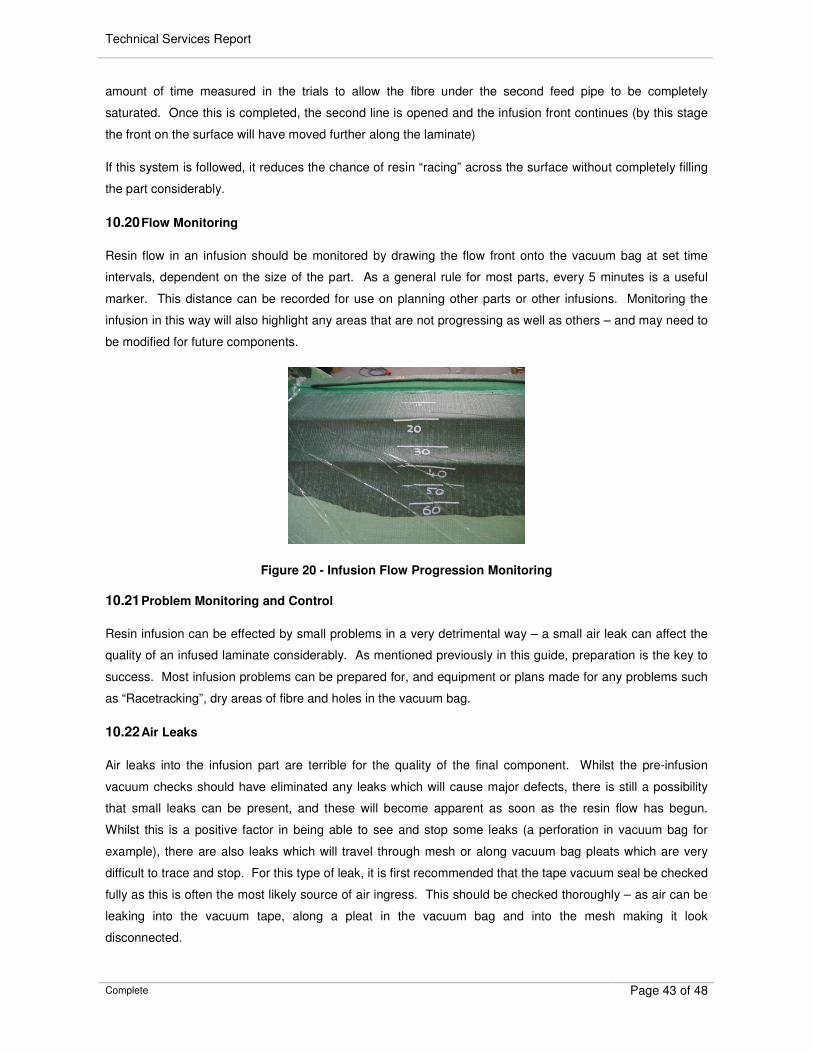
10.20 Flow Monitoring
Resin flow in an infusion should be monitored by drawing the flow front onto the vacuum bag at set time
intervals, dependent on the size of the part. As a general rule for most parts, every 5 minutes is a useful
marker. This distance can be recorded for use on planning other parts or other infusions. Monitoring the
infusion in this way will also highlight any areas that are not progressing as well as others – and may need to
be modified for future components.
Figure 20 - Infusion Flow Progression Monitoring
10.21 Problem Monitoring and Control
Resin infusion can be effected by small problems in a very detrimental way – a small air leak can affect the
quality of an infused laminate considerably. As mentioned previously in this guide, preparation is the key to
success. Most infusion problems can be prepared for, and equipment or plans made for any problems such
as “Racetracking”, dry areas of fibre and holes in the vacuum bag.
10.22 Air Leaks
Air leaks into the infusion part are terrible for the quality of the final component. Whilst the pre-infusion
vacuum checks should have eliminated any leaks which will cause major defects, there is still a possibility
that small leaks can be present, and these will become apparent as soon as the resin flow has begun.
Whilst this is a positive factor in being able to see and stop some leaks (a perforation in vacuum bag for
example), there are also leaks which will travel through mesh or along vacuum bag pleats which are very
difficult to trace and stop. For this type of leak, it is first recommended that the tape vacuum seal be checked
fully as this is often the most likely source of air ingress. This should be checked thoroughly – as air can be
leaking into the vacuum tape, along a pleat in the vacuum bag and into the mesh making it look
disconnected.
Technical Services Report
Complete Page 44 of 48
10.23 Resin “Racetracking”
The basic principles of resin infusion are such that the resin will always take the easiest path – the one with
least resistance. If there is a situation where the vacuum bag has been allowed to bridge along a corner etc,
resin will use this as the fastest course to the vacuum outlet – and will not fill the remaining laminate. For
this reason it is essential that a considerable time is spend ensure that the vacuum bag is correctly fitted and
no bridging is accepted. The laminate should be pushed into each corner using a blunt tool (so as not to
puncture the vacuum bag) to make sure that there are no resin rich areas in tight radii.
10.24 Cure
Most infusion resins have long gel times to assist in ensuring that infusions are complete before the resin
cures. Although they will cure, these resins tend to be very pure epoxy based and may require the addition
of some heat before they are strong enough to allow the component to be demoulded. It is generally best to
give a component a cure at 40 Deg C for over 10 hours if possible before it is demoulded to allow the full
dimensional stability to increase. Once this has been completed, the part can be left without a postcure until
it is completed if required. It is important that health and safety guidelines are followed at all times when
using epoxy, but this is especially important in this stage. Resin can be very brittle when the vacuum bag
and consumables are being removed and at this stage the wearing of full PPE is essential as the epoxy is
not yet fully cured, even though it is hard.
10.25 Postcure
Epoxy Infusion components can be postcured in exactly the same way that other advanced composite
components are, although some care will be required after the resin has cured and before postcure. During
this stage the resin can be very brittle due to its chemical nature, and will therefore only demonstrate
relatively low inter-laminar shear resistance and impact resistance. It is advisable to apply a suitable
postcure as soon as possible, ensuring to ramp the heat slowly up to the required level if a high Tg is
required, otherwise a slow ramp to 50 Deg C, which is held for 16hours for a universal postcure on Gurit
resins.
Technical Services Report
Complete Page 45 of 48
11. CALCULATIONS AND DATA
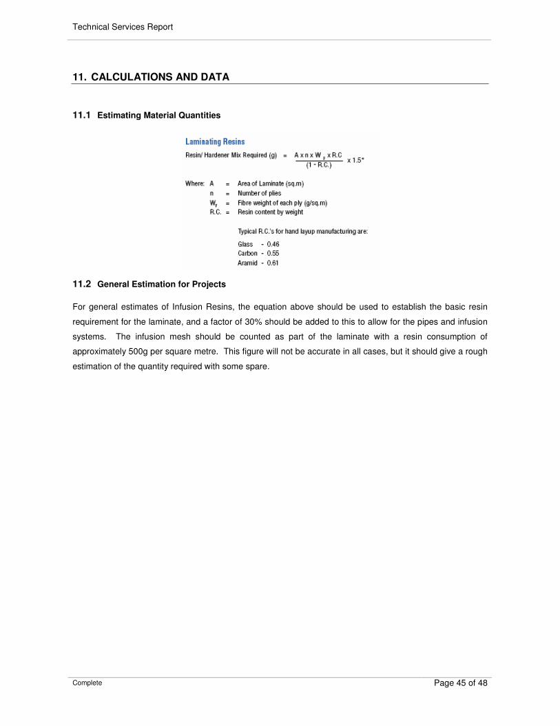
11.1 Estimating Material Quantities
11.2 General Estimation for Projects
For general estimates of Infusion Resins, the equation above should be used to establish the basic resin
requirement for the laminate, and a factor of 30% should be added to this to allow for the pipes and infusion
systems. The infusion mesh should be counted as part of the laminate with a resin consumption of
approximately 500g per square metre. This figure will not be accurate in all cases, but it should give a rough
estimation of the quantity required with some spare.
Technical Services Report
Complete Page 46 of 48
12. EXAMPLES OF INFUSION DESIGN
12.1 Monolithic Components
Figure 21 - Wind Energy Blade Mould Tool
This Wind Turbine Blade mould tool was produced on a plug and was infused in a single infusion. The
laminate is a varied monolithic skin of quadraxials and unidirectional in glass and carbon. The main laminate
is 11mm thickness and this is increased to 15mm thickness around the flanges. The infusion took 2 hours
and a total of 920kg of T-Prime 130 resin was infused. There were a total of 27 resin inlet points, and 16
vacuum outlets to control the resin flow on 14 main infusion lines.
12.1.1 Flat Panel
12.1.2 Automotive Component
Technical Services Report
Complete Page 47 of 48
Figure 22 - Racing Car Seat Tool
This racing car seat tool was manufactured over a plug and is 10mm solid carbon. The fibres are mainly
woven twill fabrics with Knitflow 40 mesh. The resin was introduced through one central infusion line across
the back of the seat, with vacuum outlets around the outside split into three pieces to allow full control.
12.1.3 Powerboat Tool
Figure 23 - RIB Hull Tool
This tool was manufactured over a very accurate CNC cut plug to provide an accurate shape for the hull.
The tool was manufactured in two infusions, as there is no gelcoat and the surface finish is critical. The first
skin was 3mm carbon, and a further 10mm was applied for the second infusion.
12.2 Sandwich Construction
12.2.1 Flat Panel
Technical Services Report
Complete Page 48 of 48
12.2.2 Automotive Component
12.2.3 Yacht Hull
13. INDEX OF FIGURES
Figure 1 - Infusion Layout 6
Figure 2 - Infusion Test Panel 7
Figure 3 - Application of Spray Tack Adhesive 20
Figure 4 – Effect of Poor Tailoring on Thick Laminates 20
Figure 5 - Fibre Bridging 21
Figure 6 - Typical Resin Infused Laminate 23
Figure 7 - Typical Hand Consolidated Laminate 24
Figure 8 - Examples of Infusion Core 26
Figure 9 - Knitflow 40 Infusion Mesh 27
Figure 10 - Example of an Infusion Core 28
Figure 11 - Reinforced Infusion Hose 29
Figure 12 - Typical Infusion Feed Pipe Layout 30
Figure 13 - Infusion Feed Pipe 30
Figure 14 - Infusion Feed Pipe Print on Laminate 32
Figure 15 - Infusion Feed Pipe in Vacuum Bag Pleat 32