727
GE Energy Technical Training LM6000 GAS TURBINE GENERATOR BASIC PACKAGE FAMILIARIZATION/OPERATIONS TRAINING COURSE Navigat Borang 2012
| Date post: | 06-Jul-2018 |
| Category: |
Documents |
| Upload: | jadid-abdullah |
| View: | 1,788 times |
| Download: | 426 times |
8/18/2019 71777896 - LM6000 Package Familiarization & Operations.pdf
http://slidepdf.com/reader/full/71777896-lm6000-package-familiarization-operationspdf 1/786
GE Energy Technical Training
LM6000 GAS TURBINE GENERATOR BASICPACKAGE FAMILIARIZATION/OPERATIONS
TRAINING COURSE

8/18/2019 71777896 - LM6000 Package Familiarization & Operations.pdf
http://slidepdf.com/reader/full/71777896-lm6000-package-familiarization-operationspdf 2/786
All rights reserved by the General Electric Company. Nocopies permitted without the prior written consent ofthe General Electric Company.
The text and the classroom instruction offered with itare designed to acquaint students with generallyaccepted good practice for the operation or main-tenance of equipment and/or systems.
They do not purport to be complete nor are they
intended to be specific for the products of anymanufacturer, including those of the General ElectricCompany; and the Company will not accept anyliability whatsoever for the work undertaken on thebasis of the text or classroom instruction. Themanufacturer’s operating and maintenance specifi-cations are the only reliable guide in any specificinstance; and where they are not complete, themanufacturer should be consulted.
The materials contained in this document are intended
for educational purposes only. This document does notestablish specifications, operating procedures ormaintenance methods for any of the productsreferenced. Always refer to the official writtenmaterials (labeling) provided with the product forspecifications, operating procedures and maintenancerequirements.

8/18/2019 71777896 - LM6000 Package Familiarization & Operations.pdf
http://slidepdf.com/reader/full/71777896-lm6000-package-familiarization-operationspdf 3/786
GE Energy
Tab 1 BOC-FAM Course Introduction F-000-00-00-000-00
Tab 2 Turbine Basics F-000-00-10-000-00
Tab 3 Construction and Operation F-060-00-10-000-00
Tab 4 Turbine Support Systems F-060-00-20-000-00
Tab 5 Turbine Lube Oil System (Woodward Control) F-060-00-20-100-00
Tab 6 Variable Geometry System (Woodward Control) F-060-00-20-200-00
Tab 7 Start System (Woodward Control) F-060-00-20-050-00
Tab 8 Gas Fuel System F-060-00-20-300-00
Tab 9 Ventilation and Combustion Air System (Woodward Control) F-060-00-20-401-00
Tab 10 Water Wash System F-060-00-20-500-00
Tab 11 Vibration Monitoring System (Bently Nevada 3500) F-060-00-20-700-00
Tab 12 Fire Protection System F-060-00-20-800-00
Tab 13 Electrical Systems F-000-00-60-000-00
Tab 14 50 HZ Generator Construction F-000-00-30-100-01
Tab 15 50 HZ Generator Lube Oil System F-060-00-30-300-01
LM6000 Package Familiarization/Basic Operator CourseNavigat Borang
Indonesia2012

8/18/2019 71777896 - LM6000 Package Familiarization & Operations.pdf
http://slidepdf.com/reader/full/71777896-lm6000-package-familiarization-operationspdf 4/786
GE Energy
A Mechanical Flow and Instrument DrawingsF&ID Symbols 7236887-571231
Hydraulic Start System 7236887-571232
Ventilation and Combustion Air System 7236887-571239
Turbine Lube Oil System 7236887-571244
Generator Lube Oil System 7236887-571248
Fuel System 7236887-571260
Water Wash System 7236887-571262Instrumentation 7236887-571272
Fire Protection System FID-1217
B Electrical Drawings
Electrical Symbols 7236887-730005
TCP 7236887-730014
Control Worksheet 7236887-730146Cause & Effect Matrix 7236887-730149
C General Arrangement Drawings
Main Unit 7236887-571201
Filter House 7236887-571204
Aux Skid 7236887-571218
GLO Skid 7236887-571221
CO2 Skid GA-1217
D Engine Illustrations
LM6K Illustrations
Reference Drawings

8/18/2019 71777896 - LM6000 Package Familiarization & Operations.pdf
http://slidepdf.com/reader/full/71777896-lm6000-package-familiarization-operationspdf 5/786
Tab 1
8/18/2019 71777896 - LM6000 Package Familiarization & Operations.pdf
http://slidepdf.com/reader/full/71777896-lm6000-package-familiarization-operationspdf 6/786
GE Aero Package Training Course Introduction
Slide 1
GE Energyg
BOC/FAM Course IntroductionF-000-00-00-000-00

8/18/2019 71777896 - LM6000 Package Familiarization & Operations.pdf
http://slidepdf.com/reader/full/71777896-lm6000-package-familiarization-operationspdf 7/786
GE Aero Package Training Course Introduction
Slide 2
GE Energyg
BOC/FAM Course IntroductionF-000-00-00-000-00
This document is intended for training use only. It is not intended to cover all possible variationsin equipment or to provide for specific problems that may arise.
Technical drawings and descriptions herein are intended to illustrate conceptual examples and
do not necessarily represent as-supplied system details. System users are advised to refer todrawings of current release when conducting troubleshooting, maintenance procedures, or otheractivities requiring system information.
GE Aero Energy Products advises that all plant personnel read this training manual and the
Operation & Maintenance Manual to become familiar with the generator package, auxiliary
equipment and operation.
This manual is not a replacement for experience and judgment. The final responsibility for proper,
safe operation of the generator package lies with the Owners and Operators. Operation andperformance of auxiliary equipment and controls not furnished by GE is the sole responsibility of
the Owners and Operators.
Reproduction of this guide in whole or in part without written permission is prohibited.

8/18/2019 71777896 - LM6000 Package Familiarization & Operations.pdf
http://slidepdf.com/reader/full/71777896-lm6000-package-familiarization-operationspdf 8/786
GE Aero Package Training Course Introduction
Slide 3
GE Energyg
BOC/FAM Course IntroductionF-000-00-00-000-00
Course Objectives
This training course is designed to provide system operators with :
Understanding of basic Gas Turbine and Generator operation
Understanding of how each of the sub systems operates, individually and as part ofthe total package
Ability to initiate and maintain normal system operation
Ability to recognize system alarm and fault information and take appropriate action
Understanding of system documentationKnowledge of serviceable components and maintenance required for normaloperation
This course should be considered a mandatory prerequisite for more advanced training in
package mechanical maintenance or control system maintenance and troubleshooting.

8/18/2019 71777896 - LM6000 Package Familiarization & Operations.pdf
http://slidepdf.com/reader/full/71777896-lm6000-package-familiarization-operationspdf 9/786
GE Aero Package Training Course Introduction
Slide 4
GE Energyg
BOC/FAM Course IntroductionF-000-00-00-000-00
8/18/2019 71777896 - LM6000 Package Familiarization & Operations.pdf
http://slidepdf.com/reader/full/71777896-lm6000-package-familiarization-operationspdf 10/786
GE Aero Package Training Course Introduction
Slide 5
GE Energyg
BOC/FAM Course IntroductionF-000-00-00-000-00
OVERVIEW OF GE ENERGY PRODUCTS
GE Energy is a leading supplier of diesel and aero-derivative gas turbine packages for industrial andmarine applications, with many units operating throughout the world.
GE Energy takes single source responsibility for the total equipment package and provides field servicefor the equipment once it has been installed.
All of GE Energy’s skill and field experience is built into each unit. Customers’ needs are met withstandardized designs, which have been proven time and time again in tropical heat, desert sand andarctic cold.
For a customer with special requirements, GE Energy adds features from a list of pre-engineered options.
GE Energy provides job-site supervision and operator training, offers total plant operation andmaintenance when desired, and backs up each unit with a multi-million dollar inventory of turbine parts, aswell as a service department with trained personnel ready to perform field service anywhere in the world
— 24 hours a day, 365 days a year.
Meeting customer’s requirements for quality, dependability and outstanding service is the commitment ofGE Energy.

8/18/2019 71777896 - LM6000 Package Familiarization & Operations.pdf
http://slidepdf.com/reader/full/71777896-lm6000-package-familiarization-operationspdf 11/786
GE Aero Package Training Course Introduction
Slide 6
GE Energyg
BOC/FAM Course IntroductionF-000-00-00-000-00
SAFETY CONSIDERATIONS
The following are general safety precautions that are not related to any specific proceduresand do not appear elsewhere in this manual. Personnel must understand and apply these
precautions during all phases of operation and maintenance.
Health Hazards
Use all cleaning solvents, fuels, oil adhesives, epoxies, and catalysts in a well-ventilated area.Avoid frequent and prolonged inhalation of fumes. Concentrations of fumes of many cleaners,adhesives, and esters are toxic and cause serious adverse health effects, and possible death, ifinhaled frequently. Wear protective gloves and wash thoroughly with soap and water as soon aspossible after exposure to such materials. Take special precautions to prevent materials from
entering the eyes. If exposed, rinse the eyes in an eyebath fountain immediately and report to aphysician. Avoid spilling solvents on the skid. Review the hazard information on the appropriateMaterial Safety Data Sheet and follow all applicable personal protection requirements.
Environmental Hazards
The disposal of many cleaning solvents, fuels, oils, adhesives, epoxies, and catalysts is regulated
and, if mismanaged, could cause environmental damage. Review Material Safety Data Sheets,product bulletin information, and applicable local, state and federal disposal requirements forproper waste management practices.
8/18/2019 71777896 - LM6000 Package Familiarization & Operations.pdf
http://slidepdf.com/reader/full/71777896-lm6000-package-familiarization-operationspdf 12/786
GE Aero Package Training Course Introduction
Slide 7
GE Energyg
BOC/FAM Course IntroductionF-000-00-00-000-00
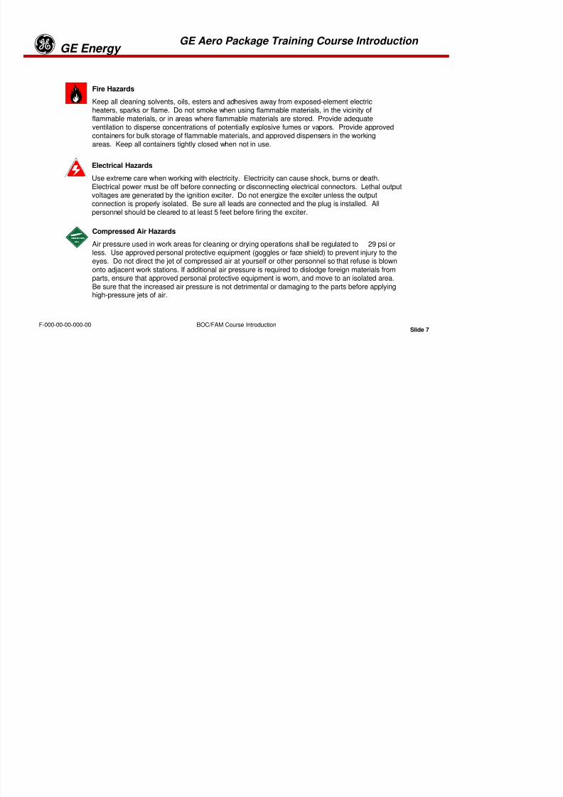
Fire Hazards
Keep all cleaning solvents, oils, esters and adhesives away from exposed-element electricheaters, sparks or flame. Do not smoke when using flammable materials, in the vicinity offlammable materials, or in areas where flammable materials are stored. Provide adequate
ventilation to disperse concentrations of potentially explosive fumes or vapors. Provide approvedcontainers for bulk storage of flammable materials, and approved dispensers in the workingareas. Keep all containers tightly closed when not in use.
Electrical Hazards
Use extreme care when working with electricity. Electricity can cause shock, burns or death.Electrical power must be off before connecting or disconnecting electrical connectors. Lethal outputvoltages are generated by the ignition exciter. Do not energize the exciter unless the outputconnection is properly isolated. Be sure all leads are connected and the plug is installed. Allpersonnel should be cleared to at least 5 feet before firing the exciter.
Compressed Air Hazards
Air pressure used in work areas for cleaning or drying operations shall be regulated to 29 psi or
less. Use approved personal protective equipment (goggles or face shield) to prevent injury to theeyes. Do not direct the jet of compressed air at yourself or other personnel so that refuse is blownonto adjacent work stations. If additional air pressure is required to dislodge foreign materials fromparts, ensure that approved personal protective equipment is worn, and move to an isolated area.Be sure that the increased air pressure is not detrimental or damaging to the parts before applyinghigh-pressure jets of air.
8/18/2019 71777896 - LM6000 Package Familiarization & Operations.pdf
http://slidepdf.com/reader/full/71777896-lm6000-package-familiarization-operationspdf 13/786
GE Aero Package Training Course Introduction
Slide 8
GE Energyg
BOC/FAM Course IntroductionF-000-00-00-000-00
Procedural Hazards
Observe all specified and logical safety practices when assembling or disassembling the engine.
Wear safety glasses or other appropriate eye protection at all times. Do not allow safety wire orwire clippings to fly from the cutter when removing or installing wire. Do not use fingers as guideswhen installing parts or checking alignment of holes. Use only correct tools and fixtures. Avoid“shortcuts,” such as using fewer-than-recommended attaching bolts or inferior-grade bolts. Heedall warnings in this manual and in all vendor manuals, to avoid injury to personnel or damage togas turbine parts.
Tooling Hazards
Improperly maintained tools and support equipment can be dangerous to personnel, and candamage gas turbine parts. Observe recommended inspection schedules to avoid unanticipatedfailures. Use tooling only for its designed purpose and avoid abuse. Be constantly alert fordamaged equipment, and initiate appropriate action for approved repair immediately.
8/18/2019 71777896 - LM6000 Package Familiarization & Operations.pdf
http://slidepdf.com/reader/full/71777896-lm6000-package-familiarization-operationspdf 14/786
GE Aero Package Training Course Introduction
Slide 9
GE Energyg
BOC/FAM Course IntroductionF-000-00-00-000-00
Gas Turbine Operational Hazards
The outside surfaces of the engine are not insulated; therefore, adequate precautions shall be taken toprevent operating personnel from inadvertently coming into contact with these hot surfaces.
The gas turbine is a source of considerable noise. It is necessary for personnel working on the gasturbine or in its vicinity to wear proper ear protection equipment when it is operating.
The gas turbine is a high-speed machine. In case of component failure, the skid housing would contain
compressor and turbine blade failures, but might not contain major compressor or turbine disk failures.Operating personnel shall not be permanently stationed in or near the plane of the rotating parts.
Low-pressure, high-velocity airflow created by the compressor can draw objects or personnel into theengine. Although an inlet screen is used, personnel should not stand in front of the inlet while the engineis operating.
When entering the gas turbine enclosure, the following requirements must be met:
•The gas turbine will be shut down or limited to core idle power.
•The fire extinguishing system will be made inactive.
•The enclosure door shall be kept open. If the gas turbine is operating, an observer shall bestationed at the enclosure door, and confined space entry procedures will be followed.
•Avoid contact with hot parts, and wear thermally insulated gloves, as necessary.
•Hearing protection (double) will be worn if the gas turbine is operating.•Do not remain in the plane of rotation of the starter when motoring the gas turbine.
When performing maintenance on electrical components, turn off electrical power to those components,except when power is required to take voltage measurements. Lock out all controls and switches, ifpossible; otherwise, tag electrical switches “Out of Service” to prevent inadvertent activation. Tag theengine operating controls “Do Not Operate” to prevent the unit from being started during a shutdowncondition.
8/18/2019 71777896 - LM6000 Package Familiarization & Operations.pdf
http://slidepdf.com/reader/full/71777896-lm6000-package-familiarization-operationspdf 15/786
GE Aero Package Training Course Introduction
Slide 10
GE Energyg
BOC/FAM Course IntroductionF-000-00-00-000-00
Cleanliness and FOD/DOD
FOD/DOD (foreign object damage/domestic object damage) is the single major cause ofpremature gas turbine failure. Prevention is the only practical means of protecting against FOD,and adherence to the following guidelines cannot be over-emphasized.
•Empty pockets of all lose objects.
•Keep maintenance area clean and organized.
•Keep FOD containers in the work area to receive bits of safety wire, used gaskets, O-rings and other similar types of debris. USE THEM.
•Do not use the gas turbine as a shelf to hold parts and tools during maintenance.
•Install protective covers and caps on all exposed openings during maintenance.
•Remove protective caps and covers only when required to install a part or make aconnection.
•After protective caps and covers are removed, inspect all openings and cavities forforeign objects and cleanliness.
•After maintenance, thoroughly clean and inspect work area. Account for all tools, parts,and materials used during maintenance.

8/18/2019 71777896 - LM6000 Package Familiarization & Operations.pdf
http://slidepdf.com/reader/full/71777896-lm6000-package-familiarization-operationspdf 16/786
Tab 2

8/18/2019 71777896 - LM6000 Package Familiarization & Operations.pdf
http://slidepdf.com/reader/full/71777896-lm6000-package-familiarization-operationspdf 17/786
Slide 1
GE Energyg
Turbine Basics
Turbine Basics
F-000-00-10-000-00
TURBINE BASICS

8/18/2019 71777896 - LM6000 Package Familiarization & Operations.pdf
http://slidepdf.com/reader/full/71777896-lm6000-package-familiarization-operationspdf 18/786
Slide 2
GE Energyg
Turbine Basics
Turbine Basics
F-000-00-10-000-00

8/18/2019 71777896 - LM6000 Package Familiarization & Operations.pdf
http://slidepdf.com/reader/full/71777896-lm6000-package-familiarization-operationspdf 19/786
Slide 3
GE Energyg
Turbine Basics
Turbine Basics
F-000-00-10-000-00
OVERVIEW
The major components of the engine are a compressor section, combustion section, and a turbine. The turbine ismechanically coupled and drives the compressor by a drive shaft.
The compressor, combustor, and turbine are called the core of the engine, since all gas turbines have these components.The core is also referred to as the gas generator (GG) since the output of the core is hot exhaust gas.
The gas is passed through an exhaust duct to atmosphere. On some types of applications, the exhaust gas is used to drivean additional turbine called the power turbine which is connected to a piece of driven equipment (i.e. generators, pumps,process compressors, etc).
Because of their high power output and high thermal efficiency, gas turbine engines are also used in a wide variety ofapplications not related to the aircraft industry. Connecting the main shaft (or power turbine) of the engine to an electro-
magnet rotor will generate electrical power. Gas turbines can also be used to power ships, trucks and military tanks. Inthese applications, the main shaft is connected to a gear box.

8/18/2019 71777896 - LM6000 Package Familiarization & Operations.pdf
http://slidepdf.com/reader/full/71777896-lm6000-package-familiarization-operationspdf 20/786
Slide 4
GE Energyg
Turbine Basics
Turbine Basics
F-000-00-10-000-00
8/18/2019 71777896 - LM6000 Package Familiarization & Operations.pdf
http://slidepdf.com/reader/full/71777896-lm6000-package-familiarization-operationspdf 21/786
Slide 5
GE Energyg
Turbine Basics
Turbine Basics
F-000-00-10-000-00
TURBINE BASICS
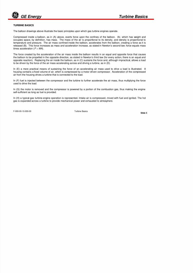
The balloon drawings above illustrate the basic principles upon which gas turbine engines operate.
Compressed inside a balloon, as in (A) above, exerts force upon the confines of the balloon. Air, which has weight andoccupies space, by definition, has mass. The mass of the air is proportional to its density, and density is proportional totemperature and pressure. The air mass confined inside the balloon, accelerates from the balloon, creating a force as it isreleased (B). This force increases as mass and acceleration increase, as stated in Newton’s second law; force equals masstimes acceleration (F = MA).
The force created by the acceleration of the air mass inside the balloon results in an equal and opposite force that causesthe balloon to be propelled in the opposite direction, as stated in Newton’s third law (for every action, there is an equal andopposite reaction). Replacing the air inside the balloon, as in (C) sustains the force and, although impractical, allows a loadto be driven by the force of the air mass accelerating across and driving a turbine, as in (D).
In (E) a more practical means of sustaining the force of an accelerating air mass used to drive a load is illustrated. Ahousing contains a fixed volume of air, which is compressed by a motor driven compressor. Acceleration of the compressedair from the housing drives a turbine that is connected to the load.
In (F) fuel is injected between the compressor and the turbine to further accelerate the air mass, thus multiplying the forceused to drive the load.
In (G) the motor is removed and the compressor is powered by a portion of the combustion gas, thus making the engineself-sufficient as long as fuel is provided.
In (H) a typical gas turbine-engine operation is represented. Intake air is compressed, mixed with fuel and ignited. The hotgas is expanded across a turbine to provide mechanical power and exhausted to atmosphere.
8/18/2019 71777896 - LM6000 Package Familiarization & Operations.pdf
http://slidepdf.com/reader/full/71777896-lm6000-package-familiarization-operationspdf 22/786
Slide 6
GE Energyg
Turbine Basics
Turbine Basics
F-000-00-10-000-00
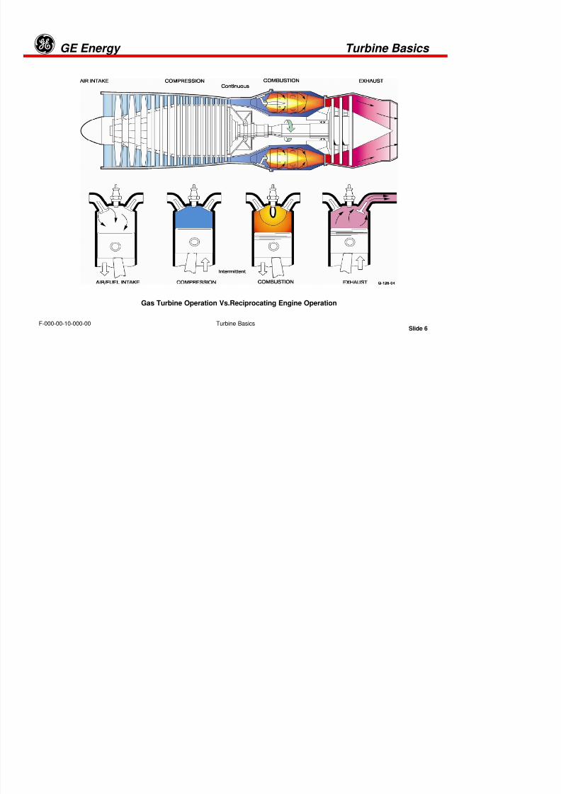
Gas Turbine Operation Vs.Reciprocating Engine Operation

8/18/2019 71777896 - LM6000 Package Familiarization & Operations.pdf
http://slidepdf.com/reader/full/71777896-lm6000-package-familiarization-operationspdf 23/786
Slide 7
GE Energyg
Turbine Basics
Turbine Basics
F-000-00-10-000-00
COMPRESSION – COMBUSTION – EXPANSION – EXHAUST
Four processes occur in gas turbine engines, as illustrated above. These processes, first described by George Braytonand called the Brayton cycle, occur in all internal combustion engines. The Brayton steps are as follows:
Compression occurs between the intake and the outlet of the compressor (Line A-B). During this process, pressure andtemperature of the air increases.
Combustion occurs in the combustion chamber where fuel and air are mixed to explosive proportions and ignited. Theaddition of heat causes a sharp increase in volume (Line BC).
Expansion occurs as hot gas accelerates from the combustion chamber. The gases at constant pressure and increasedvolume enter the turbine and expand through it. The sharp decrease in pressure and temperature (Line C-D).
Exhaust occurs at the engine exhaust stack with a large drop in volume and at a constant pressure (Line D-A).
The number of stages of compression and the arrangement of turbines that convert the energy of accelerating hot gas into
mechanical energy are design variables. However, the basic operation of all gas turbines is the same.

8/18/2019 71777896 - LM6000 Package Familiarization & Operations.pdf
http://slidepdf.com/reader/full/71777896-lm6000-package-familiarization-operationspdf 24/786
Slide 8
GE Energyg
Turbine Basics
Turbine Basics
F-000-00-10-000-00

8/18/2019 71777896 - LM6000 Package Familiarization & Operations.pdf
http://slidepdf.com/reader/full/71777896-lm6000-package-familiarization-operationspdf 25/786
Slide 9
GE Energyg
Turbine Basics
Turbine Basics
F-000-00-10-000-00
CONVERGENT AND DIVERGENT DUCTS
Compressors in gas turbine engines use convergent and divergent ducts to generate the high pressures necessary to (a)
provide a “wall of pressure,” preventing expanding hot gas from exiting through the engine inlet, as well as, through theexhaust; and (b) provide the proper ratio of air-to-fuel for efficient combustion and cooling of the combustion chamber.
Pressure decreases through convergent ducts and increases through divergent ducts, a phenomenon which isdemonstrated in paint spray equipment. Compressed air, forced through a convergent duct, generates a lower pressurethrough the narrow section to draw in paint.
Expansion through a divergent section then increases pressure and air volume, dispersing the paint in an atomized mist.
8/18/2019 71777896 - LM6000 Package Familiarization & Operations.pdf
http://slidepdf.com/reader/full/71777896-lm6000-package-familiarization-operationspdf 26/786
Slide 10
GE Energyg
Turbine Basics
Turbine Basics
F-000-00-10-000-00
8/18/2019 71777896 - LM6000 Package Familiarization & Operations.pdf
http://slidepdf.com/reader/full/71777896-lm6000-package-familiarization-operationspdf 27/786
Slide 11
GE Energyg
Turbine Basics
Turbine Basics
F-000-00-10-000-00
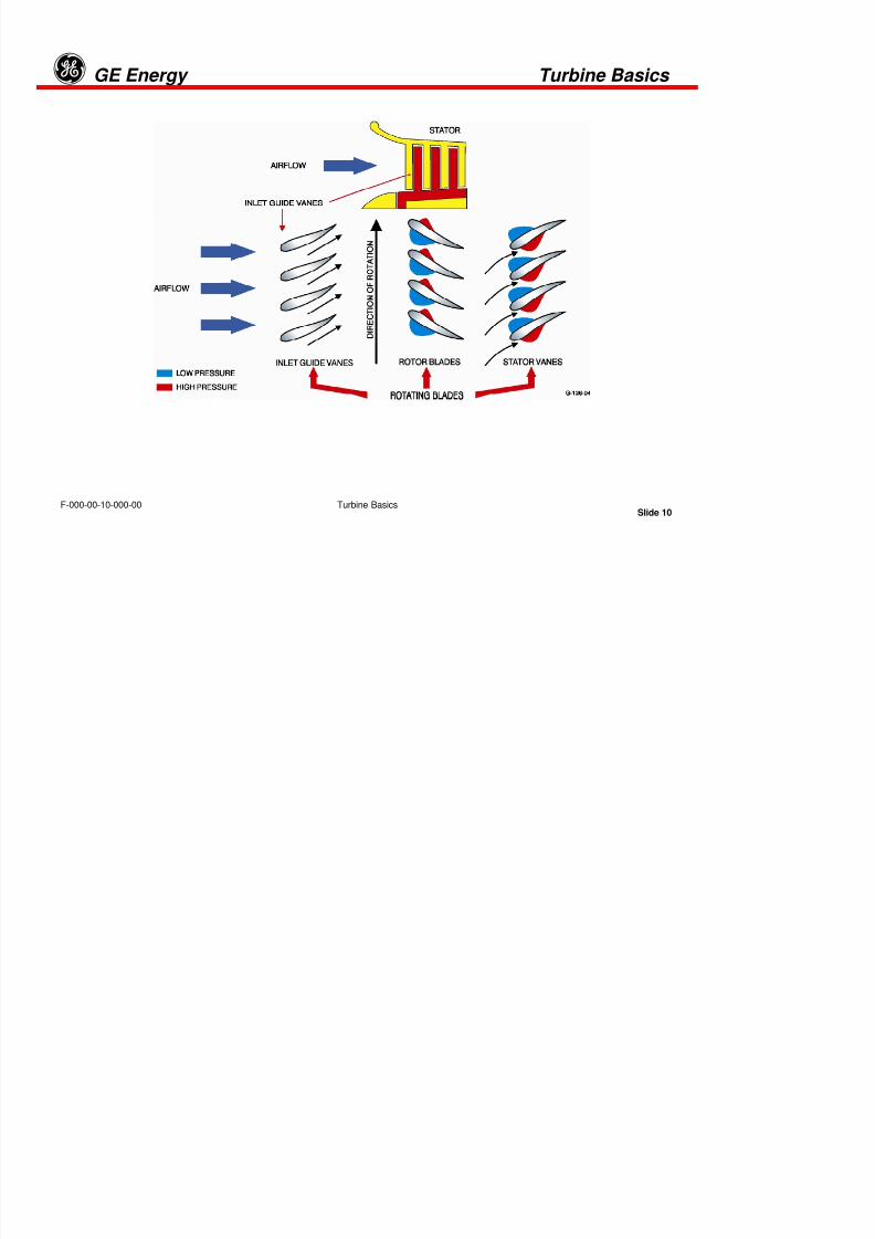
INLET GUIDE VANES
Inlet guide vanes direct, or align, airflow into the first rotating blade section where velocity is increased by the addition ofenergy. The following stator vane section is divergent, providing an increase in static pressure and a decrease in airvelocity. Airflow then enters the second stage at a higher initial velocity and pressure than at the inlet to the precedingstage. Each subsequent stage provides an incremental increase in velocity and static pressure until the desired level of
pressure and velocity is reached.
Some compressor stator vanes are designed to move, changing their divergence, allowing regulation of compressor outletpressure and velocity to achieve the proper ratio of air for fuel combustion and cooling versus engine speed and poweroutput.
8/18/2019 71777896 - LM6000 Package Familiarization & Operations.pdf
http://slidepdf.com/reader/full/71777896-lm6000-package-familiarization-operationspdf 28/786
Slide 12
GE Energyg
Turbine Basics
Turbine Basics
F-000-00-10-000-00
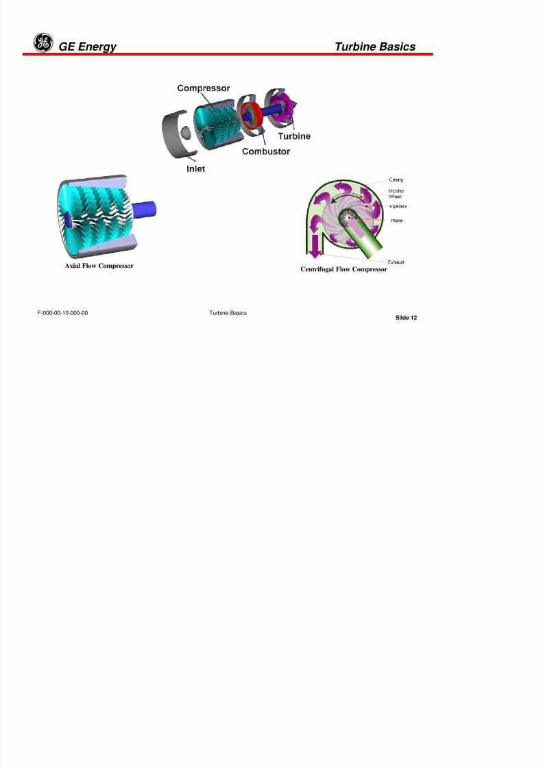
Axial Flow CompressorCentrifugal Flow Compressor
8/18/2019 71777896 - LM6000 Package Familiarization & Operations.pdf
http://slidepdf.com/reader/full/71777896-lm6000-package-familiarization-operationspdf 29/786
Slide 13
GE Energyg
Turbine Basics
Turbine Basics
F-000-00-10-000-00
COMPRESSORS
Compressors in gas turbine engines use convergent and divergent ducts to generate the high pressures necessary to (a)
provide a “wall of pressure,” preventing expanding hot gas from exiting through the engine inlet as well as through theexhaust; and (b) provide the proper ratio of air-to-fuel for efficient combustion and cooling of the combustion chamber.
Pressure decreases through convergent ducts and increases through divergent ducts, a phenomenon which isdemonstrated in paint spray equipment. Compressed air, forced through a convergent duct, generates a lower pressurethrough the narrow section to draw in paint. Expansion through a divergent section then increases pressure and airvolume, dispersing the paint in an atomized mist.
All turbine engines have a compressor to increase the pressure of the incoming air before it enters the combustor.Compressor performance has a large influence on total engine performance. There are two main types of compressors:axial and centrifugal.
In the illustration, the example on the left is called an axial compressor because the flow through the compressor travelsparallel to the axis of rotation. An apparent contradiction in the operation of the axial-flow compressor is that high pressureis generated, although the overall divergent shape would appear to cause a lower output pressure. Output pressure isincreased by divergence in each static inter-stage section. Rotating compressor blades between each static stageincreases the velocity that is lost by injecting energy.
The compressor on the right is called a centrifugal compressor because the flow through this compressor is turnedperpendicular to the axis of rotation. Centrifugal compressors, which were used in the first jet engines, are still used onsmall turbojets and turbo-shaft engines. Modern large turbojet, turbofan, and turbo-shaft engines usually use axialcompressors.
8/18/2019 71777896 - LM6000 Package Familiarization & Operations.pdf
http://slidepdf.com/reader/full/71777896-lm6000-package-familiarization-operationspdf 30/786
Slide 14
GE Energyg
Turbine Basics
Turbine Basics
F-000-00-10-000-00

8/18/2019 71777896 - LM6000 Package Familiarization & Operations.pdf
http://slidepdf.com/reader/full/71777896-lm6000-package-familiarization-operationspdf 31/786
Slide 15
GE Energyg
Turbine Basics
Turbine Basics
F-000-00-10-000-00
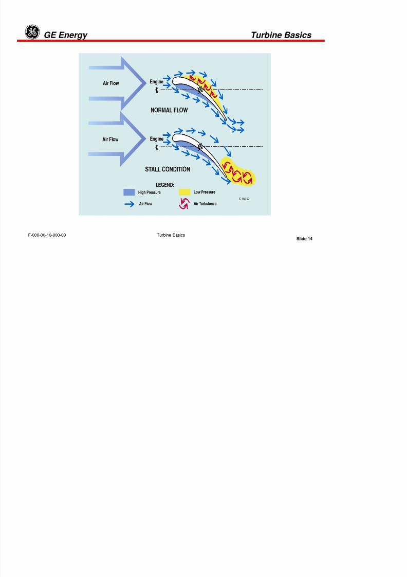
COMPRESSOR STALL
A stall can happen within the compressor if the air moves from its general direction of motion (also known as the angle ofattack). At this point, the low pressure on the upper surface disappears on the stator blade. This phenomenon is known as astall. As pressure is lost on the upper surface, turbulence created on the backside of the stator blade forms a wall that willlead into the stall. Stall can be provoked if the surface of the compressor blade is not completely even or smooth. A dent in
the blade, or a small piece of material on it, can be enough to start the turbulence on the backside of the blade, even if theangle of attack is fairly small. Each stage of compression should develop the same pressure ratio as all other stages. Whena stall occurs, the front stages supply too much air for the rear stages to handle, and the rear stage will choke.
High Angle of Attack
If the angle of attack is too high, the compressor will stall. The airflow over the upper airfoil surface will become turbulent anddestroy the pressure zone. This will decrease the compression airflow. Any action that decreases airflow relative to engine
speed will increase the angle of attack and increases the tendency to stall.
Low Angle of Attack
If there is a decrease in the engine speed, the compression ratio will decrease with the lower rotor velocities. With adecrease in compression, the volume of air in the rear of the compressor will be greater. This excess volume of air causes achoking action in the rear of the compressor with a decrease in airflow. This in turn decreases the air velocity in the front of
the compressor and increases the tendency to stall.
8/18/2019 71777896 - LM6000 Package Familiarization & Operations.pdf
http://slidepdf.com/reader/full/71777896-lm6000-package-familiarization-operationspdf 32/786
Slide 16
GE Energyg
Turbine Basics
Turbine Basics
F-000-00-10-000-00
Can Type Combustor Annular Type Combustor

8/18/2019 71777896 - LM6000 Package Familiarization & Operations.pdf
http://slidepdf.com/reader/full/71777896-lm6000-package-familiarization-operationspdf 33/786
Slide 17
GE Energyg
Turbine Basics
Turbine Basics
F-000-00-10-000-00
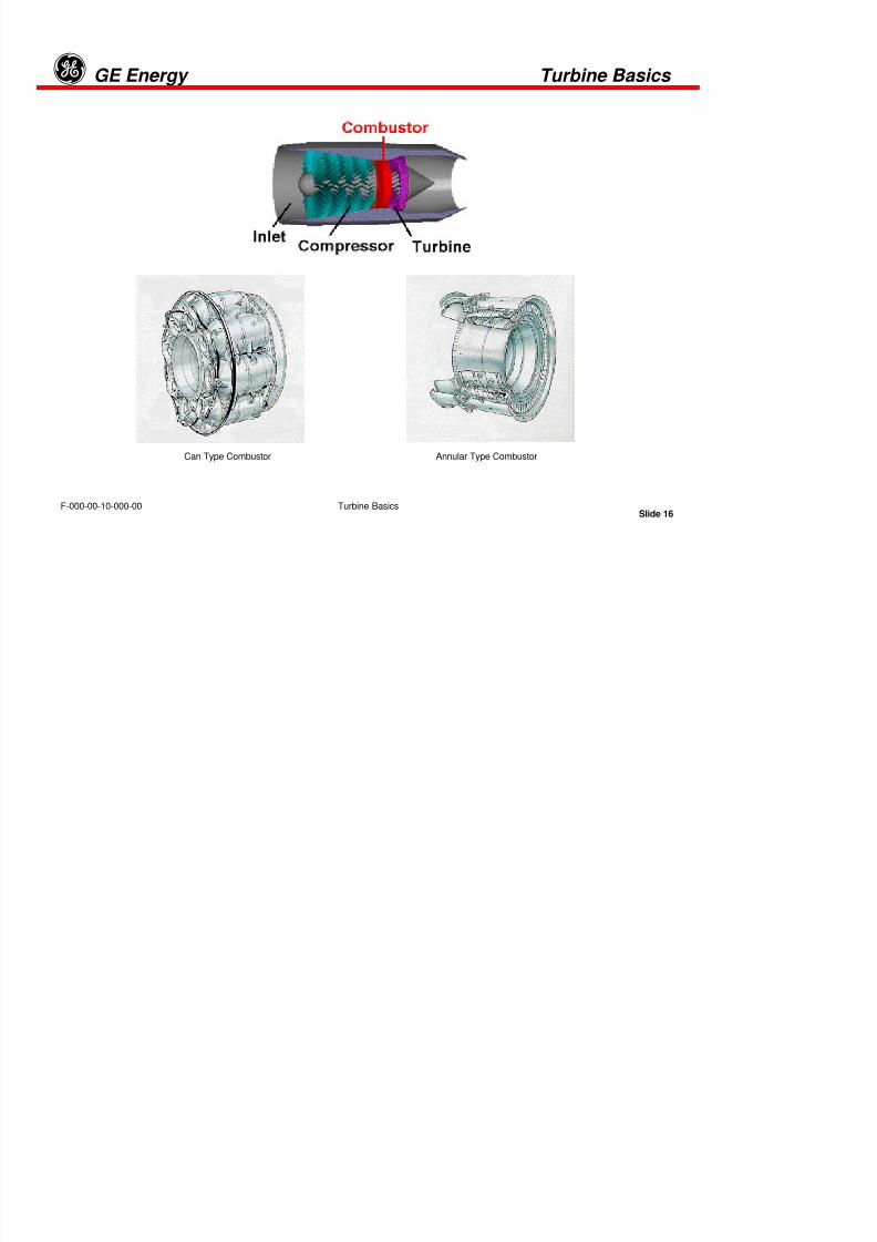
COMBUSTORS
All turbine engines have a combustor, in which the fuel is combined with high pressure air and burned. The resulting hightemperature exhaust gas is used to turn the turbine and produce thrust when passed through a nozzle.
The combustor is located between the compressor and the turbine. The combustor is arranged like an annulus, or a
doughnut, as shown by illustrations above. The central shaft that connects the turbine and compressor passes through thecenter hole. Combustors are made from materials that can withstand the high temperatures of combustion. The liner is oftenperforated to enhance mixing of the fuel and air.
There are three main types of combustors, and all three designs are found in gas turbines:
• The combustor at the right is an annular combustor with the liner sitting inside the outer casing which has been peeledopen in the drawing. Many modern combustors have an annular design.
• The combustor on the left is an older can or tubular design. Each can has both a liner and a casing, and the cans arearranged around the central shaft.
• A compromise design (not shown) is a can-annular design, in which the casing is annular and the liner is can-shaped. Theadvantage to the can-annular design is that the individual cans are more easily designed, tested, and serviced.
Turbine blades exist in a much more hostile environment than compressor blades. Located just downstream of thecombustor, turbine blades experience flow temperatures of more than a thousand degrees Fahrenheit. Turbine blades mustbe made of special materials that can withstand the heat, or they must be actively cooled. In active cooling, the nozzles and
blades are hollow and cooled by air which is bled off the compressor. The cooling air flows through the blade and outthrough the small holes on the surface to keep the surface cool.
8/18/2019 71777896 - LM6000 Package Familiarization & Operations.pdf
http://slidepdf.com/reader/full/71777896-lm6000-package-familiarization-operationspdf 34/786
Slide 18
GE Energyg
Turbine Basics
Turbine Basics
F-000-00-10-000-00

8/18/2019 71777896 - LM6000 Package Familiarization & Operations.pdf
http://slidepdf.com/reader/full/71777896-lm6000-package-familiarization-operationspdf 35/786
Slide 19
GE Energyg
Turbine Basics
Turbine Basics
F-000-00-10-000-00
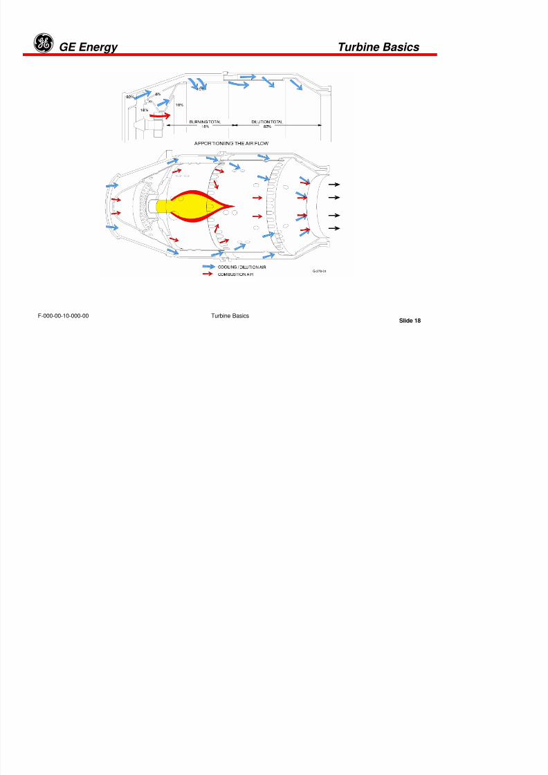
FLAME-STABILIZING AND GENERAL-FLOW PATTERNS
The flame stabilizing and general-flow patterns are illustrated above for a typical “can-type” combustion chamber.Although modern engines use one continuous annular combustion chamber, the can-type simplifies illustration of thecooling and combustion techniques used in all combustion chambers.
The temperature of the flame illustrated in the center of the combustor is approximately 3200°F at its tip when the engine isoperating at full load. Metals used in combustion chamber construction are not capable of withstanding temperatures inthis range; therefore, the design provides airflow passages between the inner and the outer walls of the chamber forcooling and flame shaping.
Air flowing into the inner chamber is directed through small holes to shape the flame centering it within the chamber, toprevent its contact with the chamber walls. Approximately 82% of the airflow into combustion chambers is used for coolingand flame shaping; only 18% is used for fuel combustion. Regulation of fuel flow determines engine speed. Stator vanecontrol in the compressor controls pressure and velocity into the combustion chamber as a function of compressor speed.

8/18/2019 71777896 - LM6000 Package Familiarization & Operations.pdf
http://slidepdf.com/reader/full/71777896-lm6000-package-familiarization-operationspdf 36/786
Slide 20
GE Energyg
Turbine Basics
Turbine Basics
F-000-00-10-000-00

8/18/2019 71777896 - LM6000 Package Familiarization & Operations.pdf
http://slidepdf.com/reader/full/71777896-lm6000-package-familiarization-operationspdf 37/786

8/18/2019 71777896 - LM6000 Package Familiarization & Operations.pdf
http://slidepdf.com/reader/full/71777896-lm6000-package-familiarization-operationspdf 38/786
Slide 22
GE Energyg
Turbine Basics
Turbine Basics
F-000-00-10-000-00

8/18/2019 71777896 - LM6000 Package Familiarization & Operations.pdf
http://slidepdf.com/reader/full/71777896-lm6000-package-familiarization-operationspdf 39/786
Slide 23
GE Energyg
Turbine Basics
Turbine Basics
F-000-00-10-000-00
TURBINE (Continued)
The compressor drive turbine is an “impulse reaction”-type designed for maximum efficiency in converting hot-gas flow intorotational mechanical energy. A first-stage fixed nozzle directs flow into the first-stage of rotating blades. The impulse ofexpanding hot gas upon the lower surface of each rotating blade propels motion in the upward direction.
Hot gas flow above the following blade creates a lower pressure above the blade as above an aircraft wing, causing
additional rotational force. Subsequent stages operate identically, multiplying the rotational force. Compressor and load-driving turbines consist of a varying number of stages, depending upon the load being driven and other designconsiderations.
g
8/18/2019 71777896 - LM6000 Package Familiarization & Operations.pdf
http://slidepdf.com/reader/full/71777896-lm6000-package-familiarization-operationspdf 40/786
Slide 24
GE Energyg
Turbine Basics
Turbine Basics
F-000-00-10-000-00
.
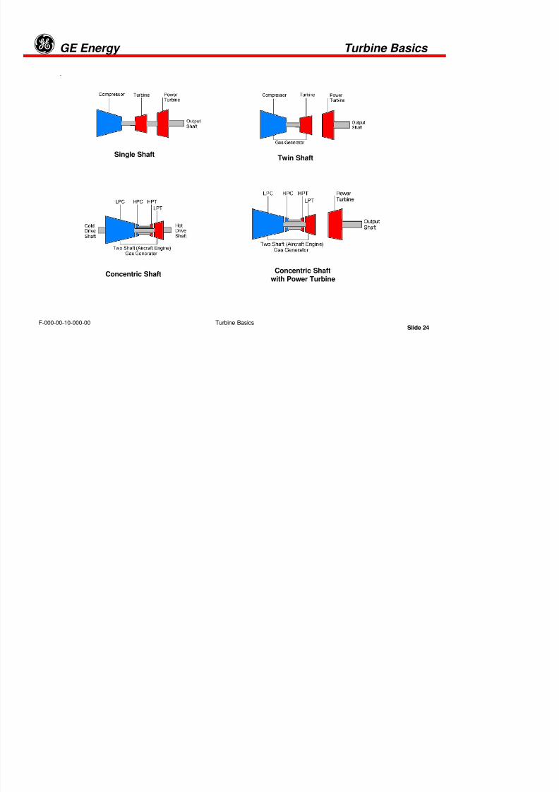
Single ShaftTwin Shaft
Concentric Shaftwith Power Turbine
Concentric Shaft
g

8/18/2019 71777896 - LM6000 Package Familiarization & Operations.pdf
http://slidepdf.com/reader/full/71777896-lm6000-package-familiarization-operationspdf 41/786
Slide 25
GE Energyg
Turbine Basics
Turbine Basics
F-000-00-10-000-00
TURBINE SHAFTS
The figure above shows the standard gas turbine shaft arrangements. Single shaft illustration is the traditional single shaftassembly. It consists of the axial flow compressor; Turbine and Power Turbine are all mechanically linked. If we add to thisshaft the generator and gearbox, we have a shaft system with a high moment of inertia. This is the favored configuration forelectrical generation because this provides additional speed (Frequency) stability of the electrical current during large loadfluctuations. This configuration is typical of heavy-duty industrial “frame” turbines, such as the MS7001.
The twin shaft illustration shows the standard two shaft arrangement with the compressor and turbine only connected, and anunconnected power turbine and output shaft that will rotate independently. This configuration is favored for variable speed-drive packages, such as pumps and compressors, because the gas generator or gas producer can run at its own optimumspeed for a given load. The LM2500 utilizes this configuration and has been applied to both electric power generation and avariety of mechanical drive applications.
Aircraft jet engines have for many years been adapted for industrial use as shown in the diagrams above. The concentricshaft illustration, above left, shows a more complicated aero-derivative industrial turbine arrangement. This, too, is stillessentially a two shaft configuration but the gas generator core (an original jet-engine) was designed with two spools, a LowPressure Shaft and a High Pressure Shaft. This engine configuration allows the load to be driven from either the exhaust endor the compressor air intake end. This is the configuration used by the LM6000
The concentric shaft with power turbine illustration is essentially a two shaft arrangement with a gas generator originally
designed for propulsion. An independently rotating Power Turbine, manufactured especially to match the flow of the jetengine, is added to the gas path as the power/torque producer. This configuration is found in the LM1600 and the LMS100.
g

8/18/2019 71777896 - LM6000 Package Familiarization & Operations.pdf
http://slidepdf.com/reader/full/71777896-lm6000-package-familiarization-operationspdf 42/786
Slide 26
GE Energyg
Turbine Basics
Turbine Basics
F-000-00-10-000-00

8/18/2019 71777896 - LM6000 Package Familiarization & Operations.pdf
http://slidepdf.com/reader/full/71777896-lm6000-package-familiarization-operationspdf 43/786

8/18/2019 71777896 - LM6000 Package Familiarization & Operations.pdf
http://slidepdf.com/reader/full/71777896-lm6000-package-familiarization-operationspdf 44/786
Tab 3
g

8/18/2019 71777896 - LM6000 Package Familiarization & Operations.pdf
http://slidepdf.com/reader/full/71777896-lm6000-package-familiarization-operationspdf 45/786
LM6000 Construction and Operation
Slide 1
GE Energyg
LM6000 Construction and OperationF-060-00-10-000-00
LM6000 CONSTRUCTION and OPERATION
g

8/18/2019 71777896 - LM6000 Package Familiarization & Operations.pdf
http://slidepdf.com/reader/full/71777896-lm6000-package-familiarization-operationspdf 46/786
LM6000 Construction and Operation
Slide 2
GE Energyg
LM6000 Construction and OperationF-060-00-10-000-00
3.1 ENGINE OVERVIEW
• Developed from CF6-80C2 turbofan engine• Liquid, Gas and Dual Fuel packages available• Steam or Water Injection and Dry Low Emissions combustor systems available• Most efficient simple-cycle gas turbine in class
g
8/18/2019 71777896 - LM6000 Package Familiarization & Operations.pdf
http://slidepdf.com/reader/full/71777896-lm6000-package-familiarization-operationspdf 47/786
LM6000 Construction and Operation
Slide 3
GE Energyg
LM6000 Construction and OperationF-060-00-10-000-00
The General Electric LM6000 gas turbine is a stationary gas turbine that is derived
from the family of CF6 jet engines. The aircraft version of the engine is called theCF6-80C2 turbofan engine and is used to drive several types of “wide body”commercial aircraft, including the Boeing 747-400.
The experience and technology of the CF6-80C2 and the well-proven LM2500 have
been applied to the LM6000 to make it one of the best engines on the market today.
Although the LM6000 gas turbine was developed recently (first application in 1992),General Electric was one of the first developers of the aero-derivative (a gas turbine
designed first as a flight engine, then redesigned for industrial use) with more than 30
million running hours. General Electric engines have an availability of 99.6% overall.
The LM (Land and Marine) series of gas turbines has the following gas turbines:
LM500, LM1500, LM1600, LM2500, LM2500+, LM5000, LM6000 ranging in power output
from 14 to 50 megawatts (MW).
g
8/18/2019 71777896 - LM6000 Package Familiarization & Operations.pdf
http://slidepdf.com/reader/full/71777896-lm6000-package-familiarization-operationspdf 48/786
LM6000 Construction and Operation
Slide 4
GE Energyg
LM6000 Construction and OperationF-060-00-10-000-00
The following changes were made to convert the CF6-80C2 to the LM6000:
• Front fan removed and inlet guide vanes added
• LP compressor from the CF6-50 / LM5000 used
• Front and rear frames adapted• Output shafts added to the front of the LPC and the back of the LPT
• Bearing 7R added• New industrial fuel system added
• Balancing disk added to the LPT
• Hydraulic control system for the variable geometry added
Since it’s introduction in 1992, the original LM6000PA was followed byintroduction of the model PB, the dry low emissions (DLE) version.
In 1998, the PC model was introduced and incorporated design changes to the
LPC, HPC, LPT, balance piston system and the fuel system. These designchanges increased shaft power output by approximately 3.4 MW, and engine
efficiency by approximately 2%.
The LM6000 PD is the LM6000 PC modified with the Dry Low Emission
Combustion System (DLE). This model made its appearance in mid-1998. DLEsystem requires changes to be made to the fuel nozzles and the annular
combustion chamber.
g

8/18/2019 71777896 - LM6000 Package Familiarization & Operations.pdf
http://slidepdf.com/reader/full/71777896-lm6000-package-familiarization-operationspdf 49/786
LM6000 Construction and Operation
Slide 5
GE Energyg
LM6000 Construction and OperationF-060-00-10-000-00
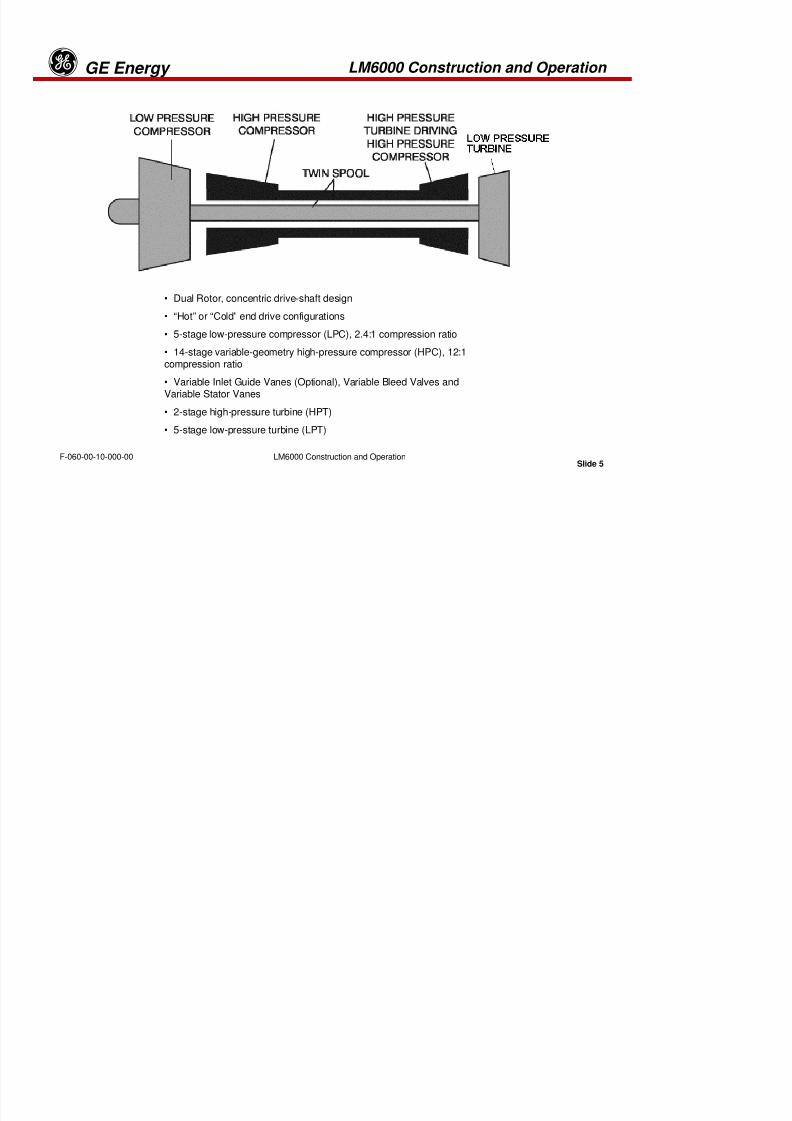
• Dual Rotor, concentric drive-shaft design
• “Hot” or “Cold” end drive configurations
• 5-stage low-pressure compressor (LPC), 2.4:1 compression ratio
• 14-stage variable-geometry high-pressure compressor (HPC), 12:1
compression ratio• Variable Inlet Guide Vanes (Optional), Variable Bleed Valves andVariable Stator Vanes
• 2-stage high-pressure turbine (HPT)
• 5-stage low-pressure turbine (LPT)
C OGg

8/18/2019 71777896 - LM6000 Package Familiarization & Operations.pdf
http://slidepdf.com/reader/full/71777896-lm6000-package-familiarization-operationspdf 50/786
LM6000 Construction and Operation
Slide 6
GE Energyg
LM6000 Construction and OperationF-060-00-10-000-00
The LM6000 gas turbine is a dual-rotor, concentric drive-shaft, gas turbine
capable of driving a load from the front and/or rear of the low-pressure (LP)rotor. The main components consist of a variable inlet guide vane (VIGV)assembly or inlet frame assembly, a 5-stage low-pressure compressor (LPC), a
14-stage variable-geometry high-pressure compressor (HPC), an annular
combustor, a 2-stage high-pressure turbine (HPT), a 5-stage low-pressure
turbine (LPT), an accessory gearbox (AGB) assembly, and accessories.
The LP rotor consists of the LPC and the LPT that drives it. Attachment
flanges are provided on both the front and the rear of the LP rotor for
connection to the packager-supplied power shaft and load. The high-pressurerotor consists of the 14-stage HPC and the 2-stage HPT that drives it. The
high-pressure (HP) core consists of the HPC, the combustor, and the HPT.The high- and low-pressure turbines drive the high- and low-pressure
compressors through concentric drive shafts.
LM6000 C t ti d O tiGE Eg

8/18/2019 71777896 - LM6000 Package Familiarization & Operations.pdf
http://slidepdf.com/reader/full/71777896-lm6000-package-familiarization-operationspdf 51/786
LM6000 Construction and Operation
Slide 7
GE Energyg
LM6000 Construction and OperationF-060-00-10-000-00
Air enters the gas turbine at the IGV/VIGVs and passes into the LPC. The LPC
compresses the air by a ratio of approximately 2.4:1. Air leaving the LPC is directedinto the HPC. Variable bypass valves (VBVs) are arranged in the flow passage
between the two compressors to regulate the airflow entering the HPC at idle and at
low power. To further control the airflow, the HPC is equipped with variable stator
vanes (VSVs).
The HPC compresses the air to a ratio of approximately 12:1, resulting in a total
compression ratio of 30:1, relative to ambient. From the HPC, the air is directedinto the single annular combustor section, where it mixes with the fuel from 30 fuel
nozzles. An igniter initially ignites the fuel-air mixture then, once combustion is
self-sustaining, the igniter is turned off. The hot gas that results from combustionis directed into the HPT that drives the HPC. This gas further expands through the
LPT, which drives the LPC and the output load.
LM6000 C t ti d O tiGE Eg

8/18/2019 71777896 - LM6000 Package Familiarization & Operations.pdf
http://slidepdf.com/reader/full/71777896-lm6000-package-familiarization-operationspdf 52/786
LM6000 Construction and Operation
Slide 8
GE Energyg
LM6000 Construction and OperationF-060-00-10-000-00
3.2 ENGINE STATIONS
LM6000 Construction and OperationGE Energyg
8/18/2019 71777896 - LM6000 Package Familiarization & Operations.pdf
http://slidepdf.com/reader/full/71777896-lm6000-package-familiarization-operationspdf 53/786
LM6000 Construction and Operation
Slide 9
GE Energyg
LM6000 Construction and OperationF-060-00-10-000-00
As in the aircraft industry, determine the left and right of the engine by looking into
the air flow or upstream. From this vantage point specific areas can be describedusing their “clock hour” positions, such as “3 o’clock” for the right side and “9o’clock” for the left side, etc.
Various signals measured on the LM6000 gas turbine are called after the so called“engine stations,” which are engine locations, numbered in the direction of airflow,from 0 to 8. Station 0 (zero) is the LP compressor inlet; station 8 is the power
turbine exhaust. Typical signal names refer to the stations. Station numbers maybe subdivided, using alphabetical character or a decimal as a suffix.
LM6000 Construction and OperationGE Energyg

8/18/2019 71777896 - LM6000 Package Familiarization & Operations.pdf
http://slidepdf.com/reader/full/71777896-lm6000-package-familiarization-operationspdf 54/786
LM6000 Construction and Operation
Slide 10
GE Energyg
LM6000 Construction and OperationF-060-00-10-000-00
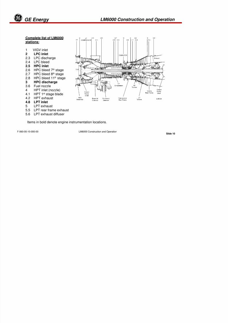
Complete list of LM6000stations:
1 VIGV inlet
2 LPC inlet2.3 LPC discharge
2.4 LPC bleed2.5 HPC inlet
2.6 HPC bleed 7th stage2.7 HPC bleed 8th stage
2.8 HPC bleed 11th stage
3 HPC discharge3.6 Fuel nozzle
4 HPT inlet (nozzle)
4.1 HPT 1st stage blade4.2 HPT exhaust4.8 LPT inlet
5 LPT exhaust5.5 LPT rear frame exhaust
5.6 LPT exhaust diffuser
Items in bold denote engine instrumentation locations.
LM6000 Construction and OperationGE Energyg
8/18/2019 71777896 - LM6000 Package Familiarization & Operations.pdf
http://slidepdf.com/reader/full/71777896-lm6000-package-familiarization-operationspdf 55/786
LM6000 Construction and Operation
Slide 11
GE Energyg
LM6000 Construction and OperationF-060-00-10-000-00
3.3 BEARINGS AND SUMPS
•Roller bearings take radial loads
•Ball bearings take radial and axial (thrust) loads
•Each rotating system uses one ball bearing
•The LP system uses the 1B bearing for axial position•The HP system uses the 4B bearing for axial position
LM6000 Construction and OperationGE Energyg

8/18/2019 71777896 - LM6000 Package Familiarization & Operations.pdf
http://slidepdf.com/reader/full/71777896-lm6000-package-familiarization-operationspdf 56/786
LM6000 Construction and Operation
Slide 12
GE Energyg
LM6000 Construction and OperationF-060-00-10-000-00
Sump A houses the No. 1B, No. 2R, and No. 3R bearings. The No. 1B bearing is a ball-
type thrust bearing that carries the thrust loads for the LP rotor (LPC and LPT). The No.2R bearing supports the low-pressure compressor rotor (LPCR) and the No. 3R bearing
supports the high-pressure compressor rotor (HPCR) forward shaft.
The B and C sump houses the No. 4R bearing, the No. 4B bearing and the No. 5Rbearing. The No. 4R bearing supports the aft shaft of the HPCR. The No. 4B bearingcarries the thrust loads for the HPR (HPC and HPT). The No. 5R bearing supportsthe high-pressure turbine rotor (HPTR) at its forward shaft.
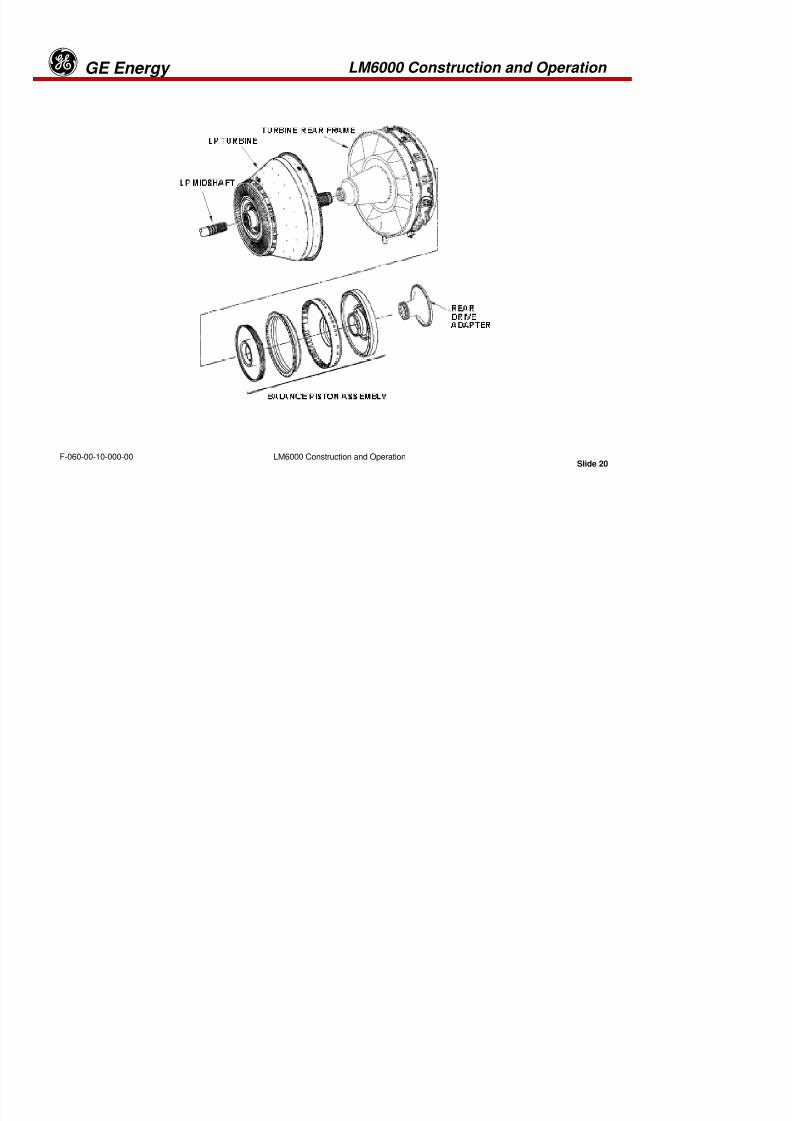
The D and E sump houses the No. 6R and No. 7R bearings. The No. 6R bearing supportsthe forward end of the low-pressure turbine rotor (LPTR) shaft. The No. 7R bearingsupports the aft end of LPTR shaft and the balance piston system.
LM6000 Construction and OperationGE Energyg
8/18/2019 71777896 - LM6000 Package Familiarization & Operations.pdf
http://slidepdf.com/reader/full/71777896-lm6000-package-familiarization-operationspdf 57/786
LM6000 Construction and Operation
Slide 13
GE Energyg
LM6000 Construction and OperationF-060-00-10-000-00
Synthetic lube oil is supplied to the bearings and scavenged out of the sumps by a
seven (7) element pump assembly. A single supply element provides lubricating oil toall the bearings and gearboxes. The remaining six elements are utilized to scavenge oil
away from the bearing sumps and gearboxes. The sump-A scavenge oil drains to thetransfer gearbox (TGB) through the 6:00 o’clock compressor front frame (CFF) strut that
houses the radial driveshaft. Oil is then scavenged through the transfer gearbox. The
No. 4R/4B and No. 5R bearing zones of the sump-B and sump-C are individuallyscavenged, as are the No. 6R and No. 7R bearing zones of the D and E sump. All sumps
emit oil mist-carrying air that is vented to a packager-supplied air-oil separator.
LM6000 Construction and OperationGE Energyg

8/18/2019 71777896 - LM6000 Package Familiarization & Operations.pdf
http://slidepdf.com/reader/full/71777896-lm6000-package-familiarization-operationspdf 58/786
LM6000 Construction and Operation
Slide 14
GE Energyg
LM6000 Construction and OperationF-060-00-10-000-00
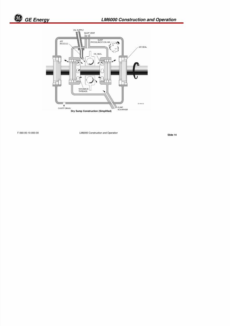
Dry Sump Construction (Simplified)
LM6000 Construction and Operation GE Energyg
8/18/2019 71777896 - LM6000 Package Familiarization & Operations.pdf
http://slidepdf.com/reader/full/71777896-lm6000-package-familiarization-operationspdf 59/786
p
Slide 15
GE Energyg
LM6000 Construction and OperationF-060-00-10-000-00
The gas turbine design uses the dry sump system to provide lubrication to the gas
turbine main bearings. The dry sump system employs five subsystems:
• Oil Supply - Oil is delivered to the bearings through jets pressurized by a supply pumpdeliver oil onto the bearings.
• Oil Scavenge - Oil scavenge is accomplished when suction, created by the pumping
action of a scavenge oil pump, is applied to a port in the lowest point of the oil-wettedcavity.
• Seal Pressurization - Bleed air, directed to the sump cavity by ports or tubes in the
engine structure, pressurizes seals.• Sump Vent - By venting the oil-wetted cavity out the top to ambient air pressure, a
positive flow of pressurizing air to the sump is maintained.• Cavity Drain - Oil leaked from the seals (sump B and sump C) is carried to an
overboard dump location.
LM6000 Construction and Operation GE Energyg
8/18/2019 71777896 - LM6000 Package Familiarization & Operations.pdf
http://slidepdf.com/reader/full/71777896-lm6000-package-familiarization-operationspdf 60/786
p
Slide 16
gyg
LM6000 Construction and OperationF-060-00-10-000-00
.
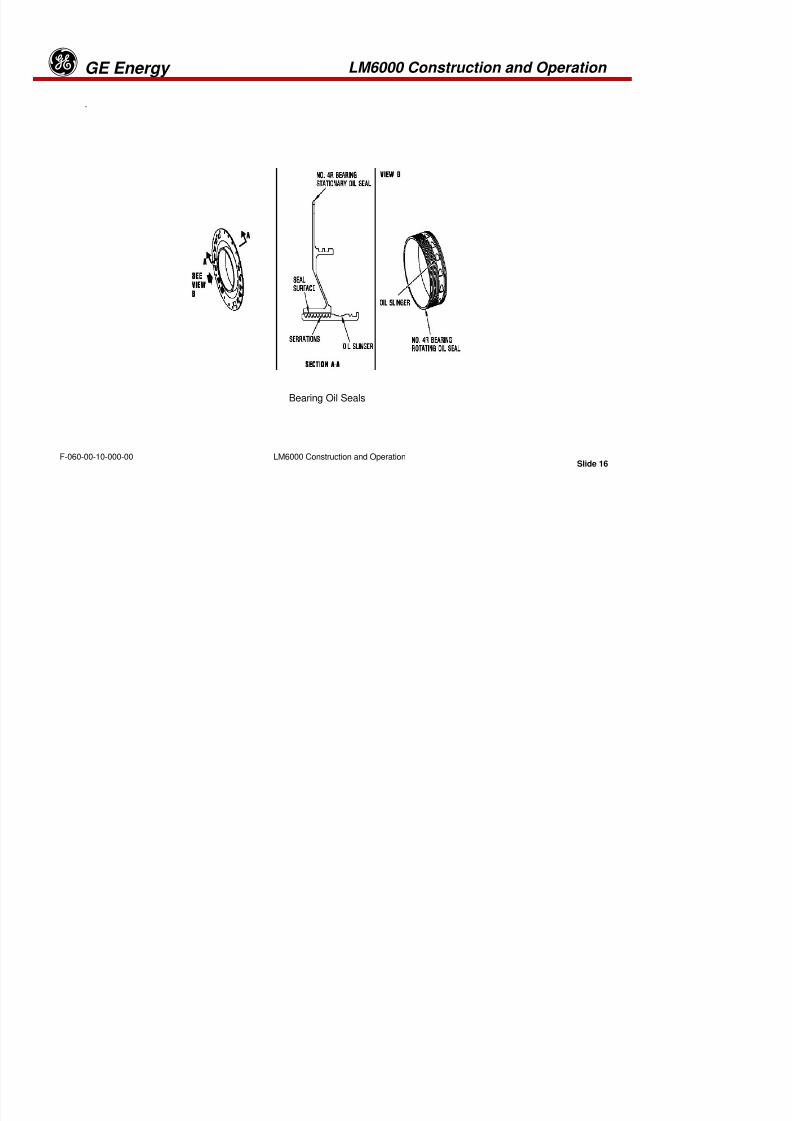
Bearing Oil Seals
LM6000 Construction and Operation GE Energyg

8/18/2019 71777896 - LM6000 Package Familiarization & Operations.pdf
http://slidepdf.com/reader/full/71777896-lm6000-package-familiarization-operationspdf 61/786
p
Slide 17
gyg
LM6000 Construction and OperationF-060-00-10-000-00
.
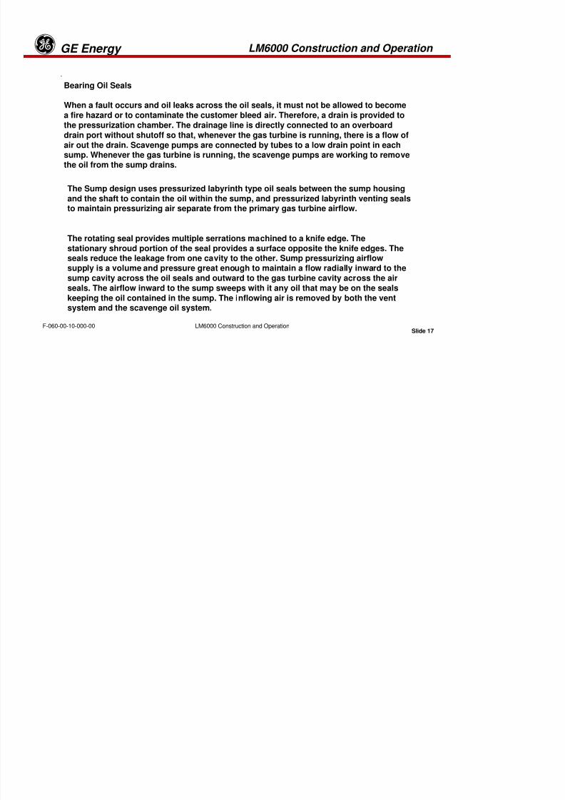
Bearing Oil Seals
When a fault occurs and oil leaks across the oil seals, it must not be allowed to become
a fire hazard or to contaminate the customer bleed air. Therefore, a drain is provided to
the pressurization chamber. The drainage line is directly connected to an overboard
drain port without shutoff so that, whenever the gas turbine is running, there is a flow ofair out the drain. Scavenge pumps are connected by tubes to a low drain point in eachsump. Whenever the gas turbine is running, the scavenge pumps are working to removethe oil from the sump drains.
The rotating seal provides multiple serrations machined to a knife edge. The
stationary shroud portion of the seal provides a surface opposite the knife edges. Theseals reduce the leakage from one cavity to the other. Sump pressurizing airflowsupply is a volume and pressure great enough to maintain a flow radially inward to the
sump cavity across the oil seals and outward to the gas turbine cavity across the air
seals. The airflow inward to the sump sweeps with it any oil that may be on the seals
keeping the oil contained in the sump. The inflowing air is removed by both the ventsystem and the scavenge oil system.
The Sump design uses pressurized labyrinth type oil seals between the sump housing
and the shaft to contain the oil within the sump, and pressurized labyrinth venting sealsto maintain pressurizing air separate from the primary gas turbine airflow.
LM6000 Construction and Operation GE Energyg

8/18/2019 71777896 - LM6000 Package Familiarization & Operations.pdf
http://slidepdf.com/reader/full/71777896-lm6000-package-familiarization-operationspdf 62/786
Slide 18
gy
LM6000 Construction and OperationF-060-00-10-000-00
3.4 MAJOR COMPONENTS
LM6000 Construction and Operation GE Energyg
8/18/2019 71777896 - LM6000 Package Familiarization & Operations.pdf
http://slidepdf.com/reader/full/71777896-lm6000-package-familiarization-operationspdf 63/786
Slide 19LM6000 Construction and OperationF-060-00-10-000-00
LM6000 Construction and Operation GE Energyg

8/18/2019 71777896 - LM6000 Package Familiarization & Operations.pdf
http://slidepdf.com/reader/full/71777896-lm6000-package-familiarization-operationspdf 64/786
Slide 20LM6000 Construction and OperationF-060-00-10-000-00
LM6000 Construction and Operation GE Energyg
8/18/2019 71777896 - LM6000 Package Familiarization & Operations.pdf
http://slidepdf.com/reader/full/71777896-lm6000-package-familiarization-operationspdf 65/786
Slide 21LM6000 Construction and OperationF-060-00-10-000-00
3.4 MAJOR COMPONENTS
• Inlet Volute
• Variable inlet guide vane (VIGV) assembly
• Low-pressure compressor (LPC) assembly
• Low-pressure compressor bypass-air collector
• Variable bypass valve system
• Low-pressure compressor front frame assembly
• High-pressure compressor (HPC) assembly
• Compressor rear frame assembly
• Combustor assembly
• High-pressure turbine assembly
• Low-pressure turbine assembly
• Turbine rear frame assembly
• Accessory gearbox
LM6000 Construction and Operation GE Energyg

8/18/2019 71777896 - LM6000 Package Familiarization & Operations.pdf
http://slidepdf.com/reader/full/71777896-lm6000-package-familiarization-operationspdf 66/786
Slide 22LM6000 Construction and OperationF-060-00-10-000-00
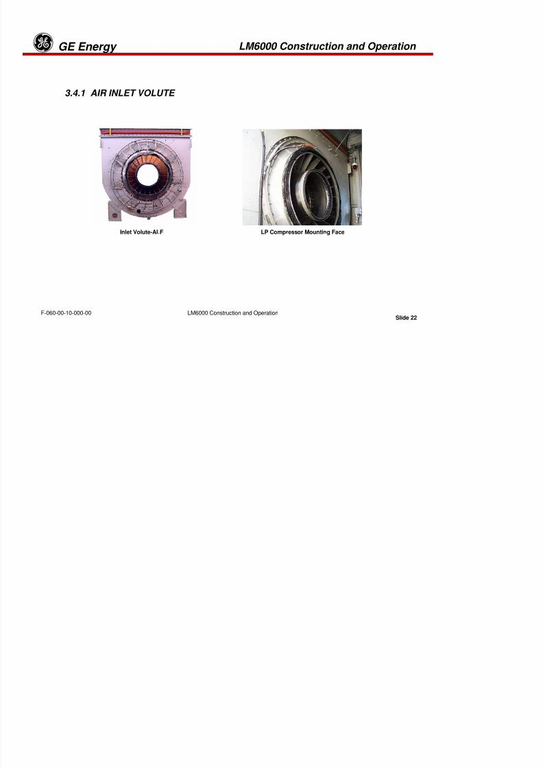
3.4.1 AIR INLET VOLUTE
Inlet Volute-ALF LP Compressor Mounting Face
LM6000 Construction and Operation GE Energyg
8/18/2019 71777896 - LM6000 Package Familiarization & Operations.pdf
http://slidepdf.com/reader/full/71777896-lm6000-package-familiarization-operationspdf 67/786
Slide 23LM6000 Construction and OperationF-060-00-10-000-00
The Air Inlet Volute provides for a smooth transition of airflow from the air filter
enclosure into the first stage of the low pressure compressor. The volute changesthe airflow direction from a vertical to a horizontal flow. The air inlet casing
assembly comprises an external casing, approximately rectangular in shape, andforms a circular internal casing to which the low pressure compressor mounts. The
generator drive shafts then runs through the center of the volute to the generator.
A flexible joint of Neoprene rubber polymer is fitted between the inlet volute and theenclosure air ducting to accommodate relative movements. A trash screen (FODscreen) is also included for additional protection against debris in the inlet system.
Mounted on the forward end (ALF) of the inlet volute are the online and offline
water wash manifolds. The LP SPRINT manifold is mounted on the rear (ALF) of
the volute. Located on the bottom of the volute is a drain line with check valvethat is plumbed to the customer provided waste fluid tank.
LM6000 Construction and Operation GE Energyg

8/18/2019 71777896 - LM6000 Package Familiarization & Operations.pdf
http://slidepdf.com/reader/full/71777896-lm6000-package-familiarization-operationspdf 68/786
Slide 24LM6000 Construction and OperationF-060-00-10-000-00
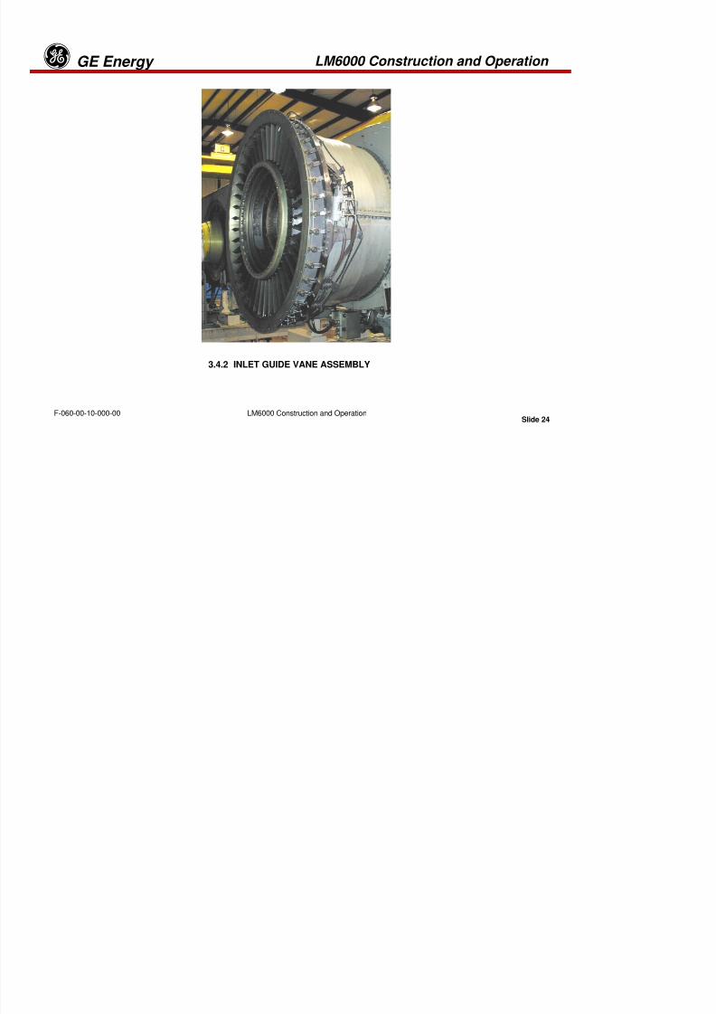
3.4.2 INLET GUIDE VANE ASSEMBLY
LM6000 Construction and Operation GE Energyg

8/18/2019 71777896 - LM6000 Package Familiarization & Operations.pdf
http://slidepdf.com/reader/full/71777896-lm6000-package-familiarization-operationspdf 69/786
Slide 25LM6000 Construction and OperationF-060-00-10-000-00
3.4.2 INLET GUIDE VANE ASSEMBLY
The air intake section is designed to interface with a radial inlet duct, which
allows inlet air to be drawn from the side or top or with an axial inlet system,
which draws air from the front. The radial inlet duct is compatible with eitherforward or rear drive installations, while the axial inlet can be used only in rear
drive installations.
The Optional Variable Inlet Guide Vane Assembly (VIGV) is located at thefront of the LPC. It allows flow modulation at partial power, resulting in
increased engine efficiency. The VIGV system consists of 43 stationary,leading-edge vanes and variable trailing flaps. The variable flaps can be
rotated from −−−−10 degrees open to +60 degrees closed by means of anactuation ring, which is driven by twin hydraulic actuators at the 3 o’clock and
9 o’clock positions. Both actuators are equipped with linear variable-differential transformers (LVDTs).
LM6000 Construction and Operation GE Energyg
8/18/2019 71777896 - LM6000 Package Familiarization & Operations.pdf
http://slidepdf.com/reader/full/71777896-lm6000-package-familiarization-operationspdf 70/786
Slide 26LM6000 Construction and OperationF-060-00-10-000-00
Normal engine operation is approximately −−−−5 degrees open (full power) to +35degrees closed (idle power). The flaps will also close during large powerreductions in order to quickly reduce the LPC flow rate and maintain the LPC stall
margin. The packager-supplied control is designed to provide excitation andsignal conditioning for both LVDTs. It also controls VIGV position by means of
closed-loop scheduling of the VIGV actuator position, based on LPC inlet
temperature (T2) and HPC discharge static pressure (PS3) corrected to gasturbine inlet pressure conditions (P0).
The VIGV system improves performance for both simple cycle and heat-
recovery cycles. It also helps minimize the variable bypass valve (VBV) flowand pressure levels, thereby reducing associated flow noise. A pressurized
rotating seal between the VIGV hub and the LPC rotor prevents ingestion ofunfiltered air into the flow path. The LM6000 PC engine can be provided with or
without the VIGV assembly. LM6000 PC models without a VIGV assembly have
a 43-strut inlet frame.
LM6000 Construction and Operation GE Energyg

8/18/2019 71777896 - LM6000 Package Familiarization & Operations.pdf
http://slidepdf.com/reader/full/71777896-lm6000-package-familiarization-operationspdf 71/786
Slide 27LM6000 Construction and OperationF-060-00-10-000-00
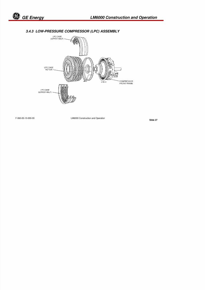
3.4.3 LOW-PRESSURE COMPRESSOR (LPC) ASSEMBLY
LM6000 Construction and Operation GE Energyg

8/18/2019 71777896 - LM6000 Package Familiarization & Operations.pdf
http://slidepdf.com/reader/full/71777896-lm6000-package-familiarization-operationspdf 72/786
Slide 28LM6000 Construction and OperationF-060-00-10-000-00
3.4.3 LOW-PRESSURE COMPRESSOR (LPC) ASSEMBLY
The forward end of the low-pressure compressor is mounted to the IGV/VIGVassembly, while the rear mounts to the Compressor Front Frame (CFF).
The LM6000 LPC is a 5-stage, axial-flow compressor with a 5-stage fixed stator.The LPC stator case contains the stator vanes for the LPC rotor. The case is
horizontally split to facilitate repair.
LM6000 Construction and Operation GE Energyg

8/18/2019 71777896 - LM6000 Package Familiarization & Operations.pdf
http://slidepdf.com/reader/full/71777896-lm6000-package-familiarization-operationspdf 73/786
Slide 29LM6000 Construction and OperationF-060-00-10-000-00
LPC Rotor
Blade Locking Lugs
LM6000 Construction and Operation GE Energyg

8/18/2019 71777896 - LM6000 Package Familiarization & Operations.pdf
http://slidepdf.com/reader/full/71777896-lm6000-package-familiarization-operationspdf 74/786
Slide 30LM6000 Construction and OperationF-060-00-10-000-00
LPC Rotor
Individual disks are used in stages 0 and 1. Stages 2 thru 4 of the LPC rotor are an
integral spool. Stages 0 and 1 blades have been modified to include squealer tips.
Stage 0 blades are individually retained in the axial dovetail slots of the disk by a one-piece blade retainer. Stages 1 thru 4 LPC blades are retained in circumferential slots in
the stage 1 disk and stages 2 thru 4 spool. The blade-retention features permit individual
blade replacement. Blades in stages 0 thru 3 can be removed without removing the rotor.
As the compressor rotates, the blades load centrifugally and become tight fitting.
LM6000 Construction and Operation GE Energyg

8/18/2019 71777896 - LM6000 Package Familiarization & Operations.pdf
http://slidepdf.com/reader/full/71777896-lm6000-package-familiarization-operationspdf 75/786
Slide 31LM6000 Construction and OperationF-060-00-10-000-00
Low Pressure Compressor Casing and Stators
LM6000 Construction and Operation GE Energyg

8/18/2019 71777896 - LM6000 Package Familiarization & Operations.pdf
http://slidepdf.com/reader/full/71777896-lm6000-package-familiarization-operationspdf 76/786
Slide 32LM6000 Construction and OperationF-060-00-10-000-00
LPC Stator Vanes
The stages 0 thru 2 stator vanes are individually replaceable. The vanes are
shrouded to reduce vane response to aerodynamic forces. Wear strips areutilized between the vane dovetails and the LPC casing slots. The stage 3
casing is a full-circumferential case and is lined with honeycomb materialover the rotor blade tips. Stage 3 vanes are bolted to the stage 3 case forward
flange. The stage 4 stator vanes are mounted in the front frame and supported
on the inside diameter by a support structure that is bolted to the engine frontframe.
LM6000 Construction and Operation GE Energyg
8/18/2019 71777896 - LM6000 Package Familiarization & Operations.pdf
http://slidepdf.com/reader/full/71777896-lm6000-package-familiarization-operationspdf 77/786
Slide 33LM6000 Construction and OperationF-060-00-10-000-00
3.4.6 LOW PRESSURE COMPRESSOR BYPASS AIR COLLECTOR
The LPC bypass-air collector is a duct attached to the front frame. It collects LPC
discharge air, vented through the LPC bypass doors, and directs it overboardthrough packager-provided ducting.
LM6000 Construction and Operation GE Energyg
8/18/2019 71777896 - LM6000 Package Familiarization & Operations.pdf
http://slidepdf.com/reader/full/71777896-lm6000-package-familiarization-operationspdf 78/786
Slide 34LM6000 Construction and OperationF-060-00-10-000-00
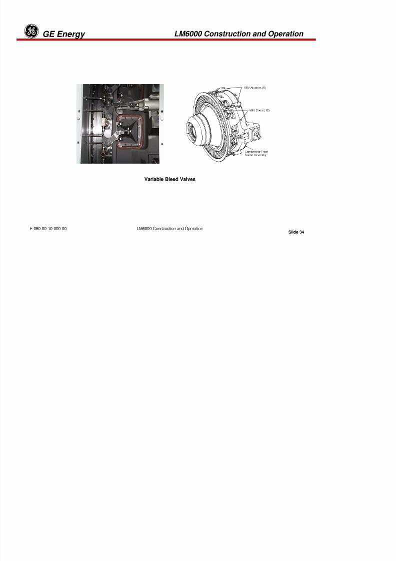
Variable Bleed Valves
LM6000 Construction and Operation GE Energyg
8/18/2019 71777896 - LM6000 Package Familiarization & Operations.pdf
http://slidepdf.com/reader/full/71777896-lm6000-package-familiarization-operationspdf 79/786
Slide 35
LM6000 Construction and OperationF-060-00-10-000-00
Variable Bypass Valve System
The variable bypass valve (VBV) system is located in the front frame assembly. This
system is used to vent LPC discharge air overboard through the LPC bypass-air
collector in order to maintain LPC stall margin during starting, partial power operation,
and large power transients. The VBV system consists of 12 variable-position bypassvalves, 6 VBV actuators (two with LVDTs) Linear Variable Differential Transformer, 6actuator bell cranks, 12 VBV doorbell cranks, and an actuation ring.
Actuators are installed at the 1 o’clock, 3 o’clock, 5 o’clock, 7 o’clock, 9 o’clock, and 11o’clock positions on the engine. The six actuators are positioned with one VBV door on
each side of each actuator. Bell cranks and pushrods mechanically link the actuators, theactuation ring, and the VBV doors. The actuator positions the actuation ring, which opens
and closes the VBV doors. The 5 o’clock and 11 o’clock position actuators are equipped
with integral LVDTs for position indication. The packager-supplied control is designed to
provide excitation and signal conditioning for both LVDTs and, to control VBV position bymeans of closed-loop scheduling of VBV actuator position, based on LPC inlet
temperature (T2) and high-pressure (HP) rotor speed corrected to inlet conditions(XN2.5R2).
LM6000 Construction and Operation GE Energyg

8/18/2019 71777896 - LM6000 Package Familiarization & Operations.pdf
http://slidepdf.com/reader/full/71777896-lm6000-package-familiarization-operationspdf 80/786
Slide 36
LM6000 Construction and OperationF-060-00-10-000-00
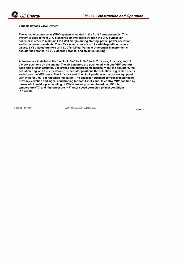
3.4.7 LOW PRESSURE COMPRESSOR FRONT FRAME ASSEMBLY
LM6000 Construction and Operation GE Energyg
8/18/2019 71777896 - LM6000 Package Familiarization & Operations.pdf
http://slidepdf.com/reader/full/71777896-lm6000-package-familiarization-operationspdf 81/786
Slide 37
LM6000 Construction and OperationF-060-00-10-000-00
3.4.7 LOW PRESSURE COMPRESSOR FRONT FRAME ASSEMBLY
The front frame is a major structure that provides support for the LPC rotor and
the forward end of the HPC rotor through the No. 1B, No. 2R, and No. 3R bearings.
The frame also forms an airflow path between the LPC and the HPC inlet. Front
engine mount provisions are located on the front frame 3 o’clock and 9 o’clockpositions. One pad is included on the frame outer case for mounting HPC inlet
temperature sensors T2.5 and HPC pressure sensor P2.5. The sensors provide
control information to the fuel management system.
The front frame is made from a high-strength stainless steel casting. Twelve
equally spaced radial struts are used between the hub and outer case to providesupport for the inner hub. Twelve variable-position bypass valve doors are
located on the outer wall for LPC discharge bleed.
The front frame contains the engine A-sump, which includes a thrust bearing(1B) and roller bearing (2R) that support the LPC rotor, and a roller bearing(3R) that supports the forward end of the HPC rotor. Lubrication oil supply andscavenge lines for the A sump are routed inside the frame struts. The inlet
gearbox is located in the A sump with the radial drive shaft extending outward
through the strut located at the 6 o’clock position.
LM6000 Construction and Operation GE Energyg

8/18/2019 71777896 - LM6000 Package Familiarization & Operations.pdf
http://slidepdf.com/reader/full/71777896-lm6000-package-familiarization-operationspdf 82/786
Slide 38
LM6000 Construction and OperationF-060-00-10-000-00
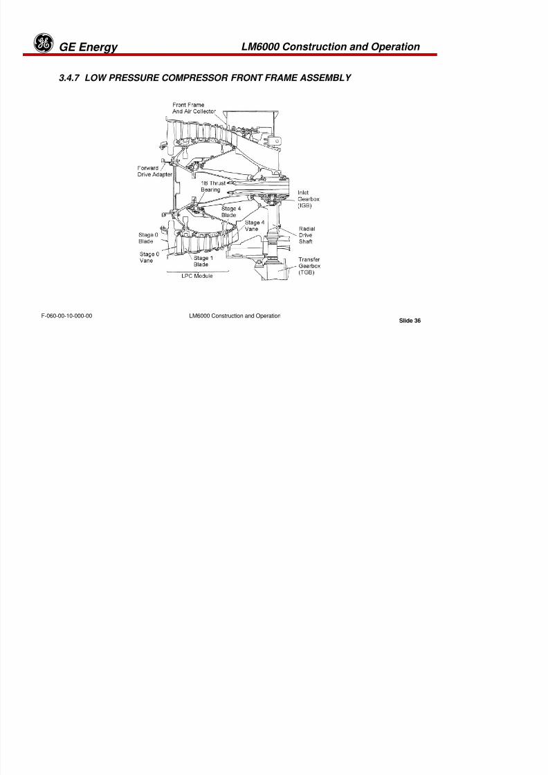
Inlet Gearbox
Radial DriveShaft
LM6000 Construction and Operation GE Energyg
8/18/2019 71777896 - LM6000 Package Familiarization & Operations.pdf
http://slidepdf.com/reader/full/71777896-lm6000-package-familiarization-operationspdf 83/786
Slide 39
LM6000 Construction and OperationF-060-00-10-000-00
Radial Drive Assembly
The radial drive shaft assembly is located in the 6 o’clock CFF strut. The shafts
serve to transmit torque from the Inlet Gearbox (IGB) to the Transfer Gearbox (TGB).
The drive shaft assembly consists of three machined, tubular steel shafts, housing,and bearings.
The upper radial shaft is splined at the upper end to the IGB and at the lower end to
the radial mid-shaft. The shaft is enclosed by the front frame and supported by a ballbearing at its lower end. The radial mid-shaft is splined at the upper end to the uppershaft and at the lower end to the lower shaft. The mid-shaft is enclosed in a housing
and supported by a ball bearing at its lower end. The lower radial shaft is splined at
the upper end to the mid-shaft and at its lower end to the TGB. The lower shaft is
enclosed by the radial adapter portion of the TGB.
LM6000 Construction and Operation GE Energyg

8/18/2019 71777896 - LM6000 Package Familiarization & Operations.pdf
http://slidepdf.com/reader/full/71777896-lm6000-package-familiarization-operationspdf 84/786
Slide 40
LM6000 Construction and OperationF-060-00-10-000-00
HPC CASE(LOWER HALF)
HPC ROTOR
HPC CASE(UPPER HALF)
G-66-04
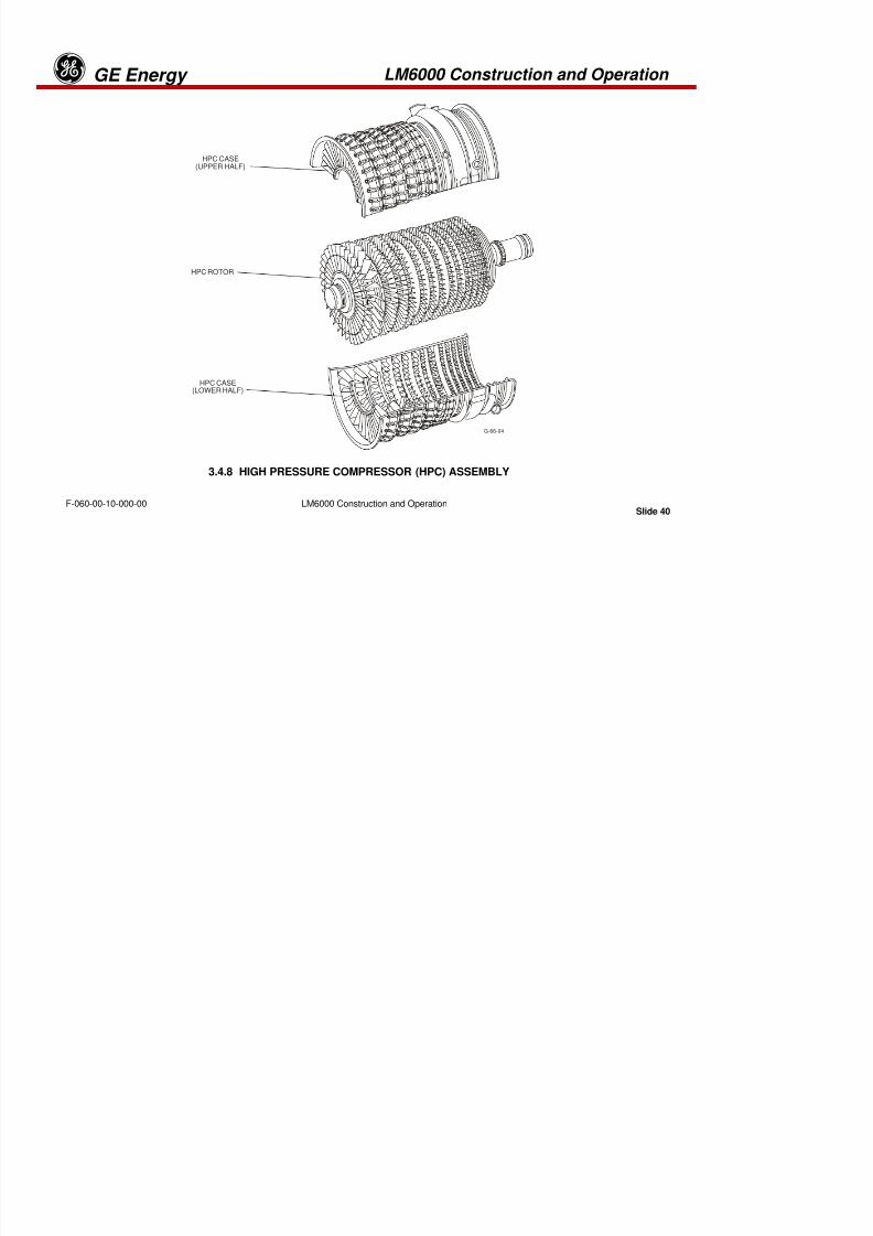
3.4.8 HIGH PRESSURE COMPRESSOR (HPC) ASSEMBLY
LM6000 Construction and Operation GE Energyg
8/18/2019 71777896 - LM6000 Package Familiarization & Operations.pdf
http://slidepdf.com/reader/full/71777896-lm6000-package-familiarization-operationspdf 85/786
Slide 41
LM6000 Construction and OperationF-060-00-10-000-00
3.4.8 HIGH PRESSURE COMPRESSOR (HPC) ASSEMBLY
The LM6000 HPC is a 14-stage, axial-flow compressor. It incorporates VIGVs and
variable stators in stages 0–5 to provide stall-free operation and high efficiencythroughout the starting and operating range. Provisions for customer-use bleed airare available at stage 8 and at the compressor discharge. On earlier PA/PB model
turbines the seventh and eleventh stages bleed air is utilized, while, later versions
(PC/PD) use eighth and eleventh stage bleed air. Compressor discharge air isextracted for cooling and pressurization of the engine components.
LM6000 Construction and Operation GE Energyg

8/18/2019 71777896 - LM6000 Package Familiarization & Operations.pdf
http://slidepdf.com/reader/full/71777896-lm6000-package-familiarization-operationspdf 86/786
Slide 42
LM6000 Construction and OperationF-060-00-10-000-00
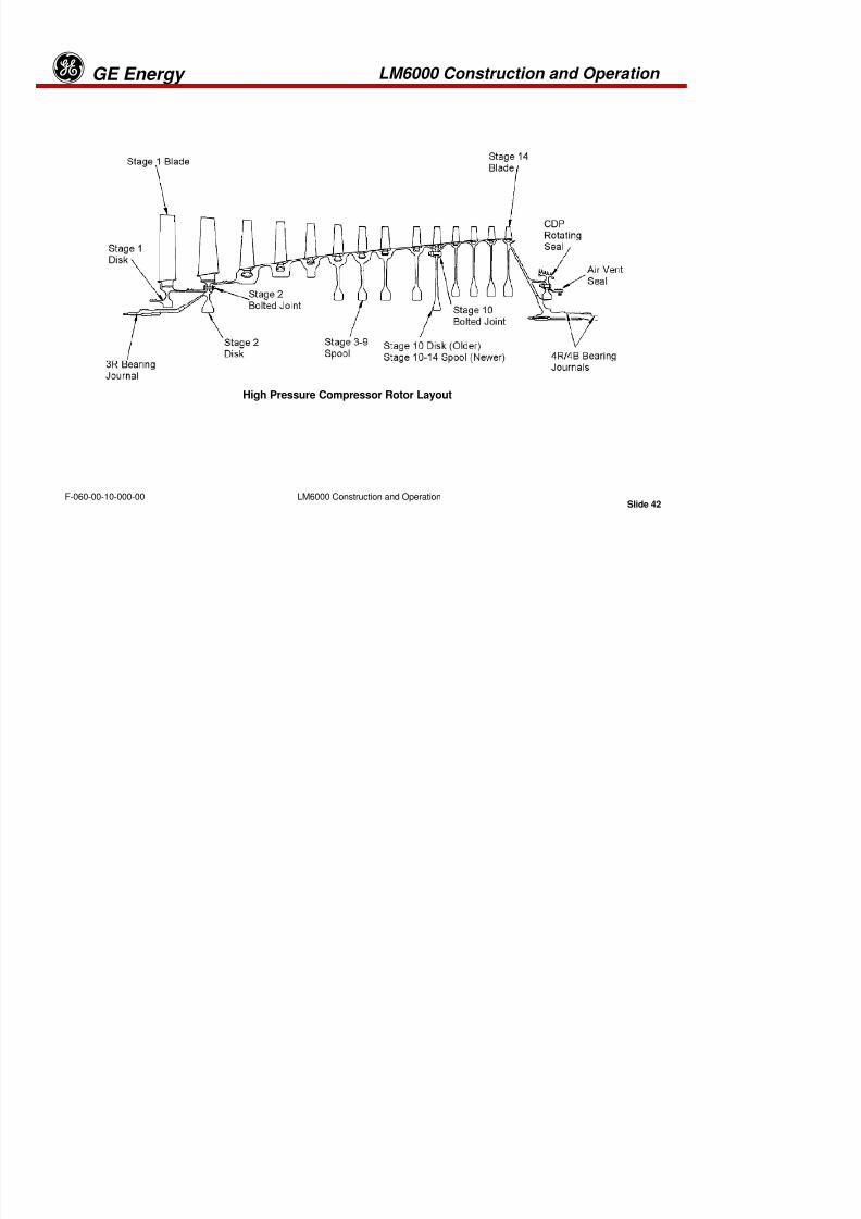
High Pressure Compressor Rotor Layout
LM6000 Construction and Operation GE Energyg

8/18/2019 71777896 - LM6000 Package Familiarization & Operations.pdf
http://slidepdf.com/reader/full/71777896-lm6000-package-familiarization-operationspdf 87/786
Slide 43
LM6000 Construction and OperationF-060-00-10-000-00
HPC Rotor
The HPC rotor is a bolted assembly of five major structural elementsconsisting of a stage 1 disk, a stage 2 disk with an integral forward
shaft, stages 3–9 spool, a stage 10 disk, and stages 11–14 spool with an
integral rear shaft. These structural elements are connected throughfully rabbeted joints at stage 2 and stage 10. On newer model HPC there
are only four major structural elements. In these versions, the 10th stage
disk has been deleted and added as an integral component of the 10--14stage spool assembly.
LM6000 Construction and Operation GE Energyg

8/18/2019 71777896 - LM6000 Package Familiarization & Operations.pdf
http://slidepdf.com/reader/full/71777896-lm6000-package-familiarization-operationspdf 88/786
Slide 44
LM6000 Construction and OperationF-060-00-10-000-00
Typical Blade Profiles
LM6000 Construction and Operation GE Energyg
8/18/2019 71777896 - LM6000 Package Familiarization & Operations.pdf
http://slidepdf.com/reader/full/71777896-lm6000-package-familiarization-operationspdf 89/786
Slide 45
LM6000 Construction and OperationF-060-00-10-000-00
Disk 1 and 2 Loading
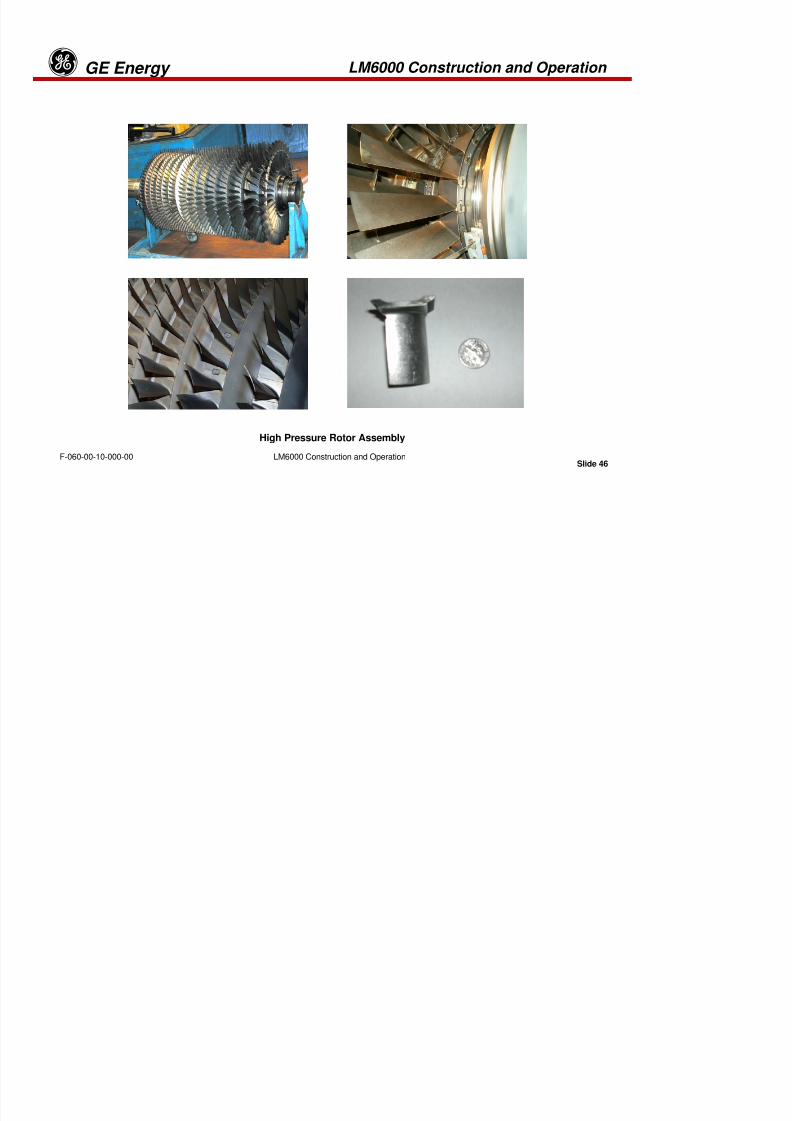
Stages 1 and 2 blades are individually retained in axial dovetail slots, and the remainingblades are held in circumferential dovetail slots. These features allow individual stage 1blade replacement without disassembly of the rotor.
Stage 1 blades are shrouded at mid-span for the purpose of reducing vibratory stress. All
other blades are cantilevered from the rotor structure.
LM6000 Construction and Operation GE Energyg
8/18/2019 71777896 - LM6000 Package Familiarization & Operations.pdf
http://slidepdf.com/reader/full/71777896-lm6000-package-familiarization-operationspdf 90/786
Slide 46
LM6000 Construction and OperationF-060-00-10-000-00
High Pressure Rotor Assembly
LM6000 Construction and Operation GE Energyg
HP STATORCASE (UPPER)

8/18/2019 71777896 - LM6000 Package Familiarization & Operations.pdf
http://slidepdf.com/reader/full/71777896-lm6000-package-familiarization-operationspdf 91/786
Slide 47
LM6000 Construction and OperationF-060-00-10-000-00
G-145-04
HP STATOR
CASE (LOWER)
HP STATORCASE (UPPER)
VARIABLE STATOR VANES
VIGV
STAGE 1
VANES
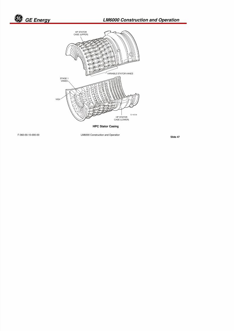
HPC Stator Casing
LM6000 Construction and Operation GE Energyg
8/18/2019 71777896 - LM6000 Package Familiarization & Operations.pdf
http://slidepdf.com/reader/full/71777896-lm6000-package-familiarization-operationspdf 92/786
Slide 48
LM6000 Construction and OperationF-060-00-10-000-00
HPC STATOR
The HPC stator consists of a cast stator case that contains the compressor statorvanes. The inlet guide vanes and the stages 1–5 vanes can be rotated about the axis
of their mounting trunnions to vary the pitch of the airfoils in the compressor flow
path. Vane airfoils in the remaining stages are stationary. All fixed and variablevanes are non-interchangeable with other stages to prevent incorrect assembly. The
casing is split along the horizontal split-line for ease of assembly and maintenance.
The inlet guide vanes and the stages 1 and 2 vane shrouds also support interstagerotor seals. The shrouds are designed to allow the removal of either half of the
compressor casing. There are 14 axial stations provided for borescope inspection ofblades and vanes.
LM6000 Construction and Operation GE Energyg

8/18/2019 71777896 - LM6000 Package Familiarization & Operations.pdf
http://slidepdf.com/reader/full/71777896-lm6000-package-familiarization-operationspdf 93/786
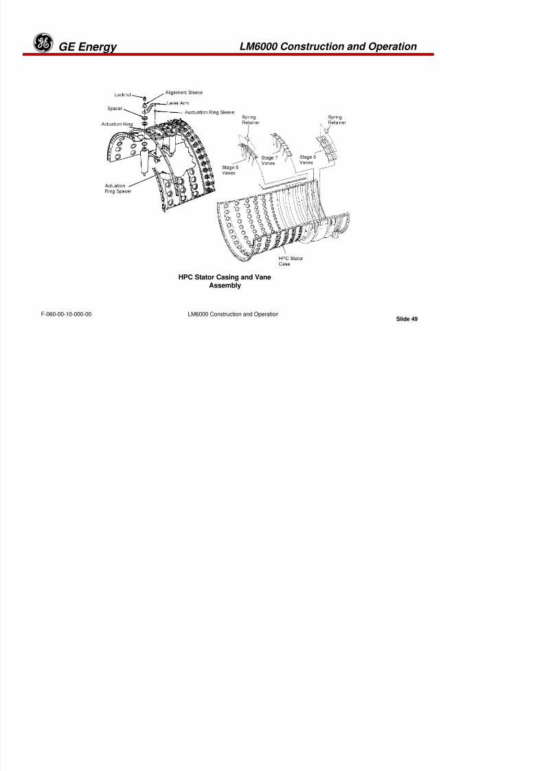
Slide 49
LM6000 Construction and OperationF-060-00-10-000-00
HPC Stator Casing and VaneAssembly
LM6000 Construction and Operation GE Energyg
8/18/2019 71777896 - LM6000 Package Familiarization & Operations.pdf
http://slidepdf.com/reader/full/71777896-lm6000-package-familiarization-operationspdf 94/786
Slide 50
LM6000 Construction and OperationF-060-00-10-000-00
LM6000 Construction and Operation GE Energyg
8/18/2019 71777896 - LM6000 Package Familiarization & Operations.pdf
http://slidepdf.com/reader/full/71777896-lm6000-package-familiarization-operationspdf 95/786
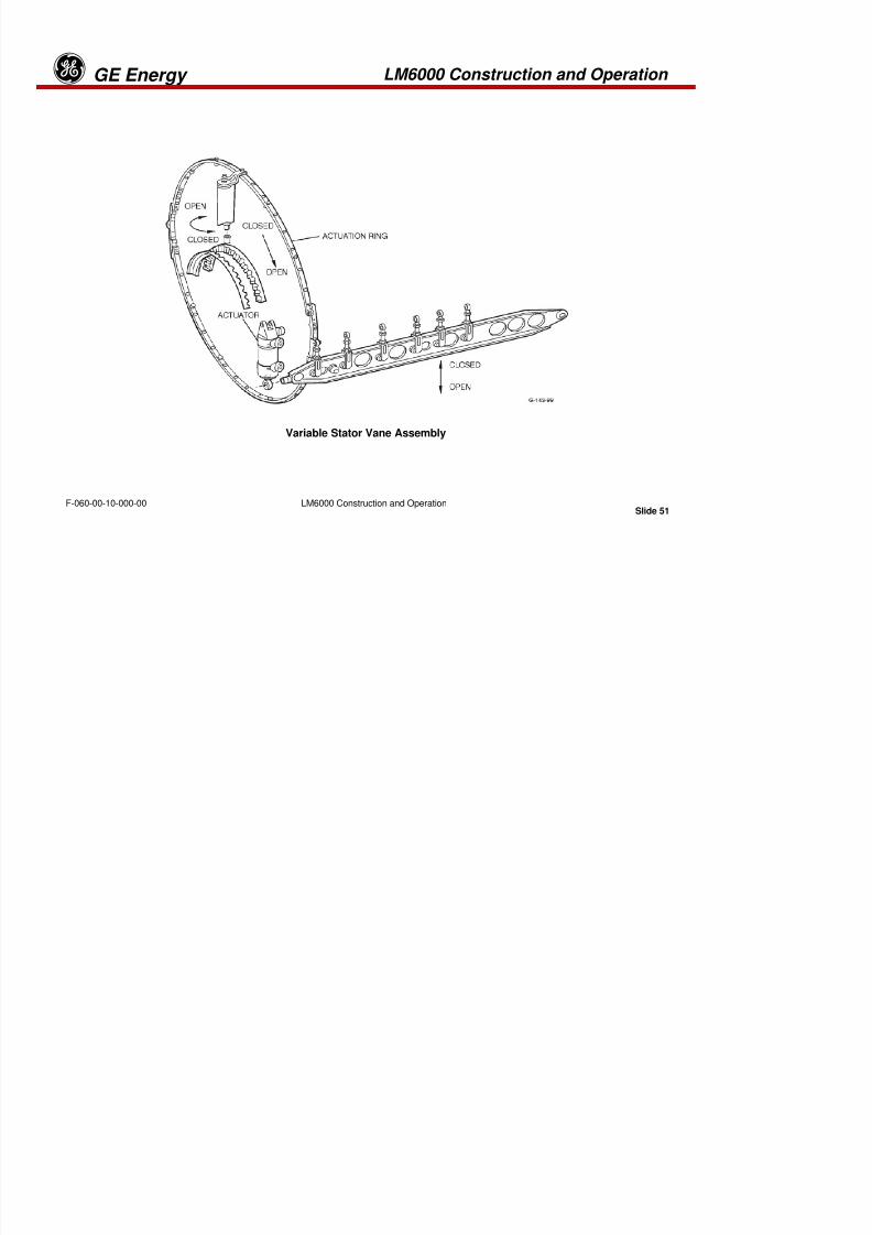
Slide 51
LM6000 Construction and OperationF-060-00-10-000-00
Variable Stator Vane Assembly
LM6000 Construction and Operation GE Energyg
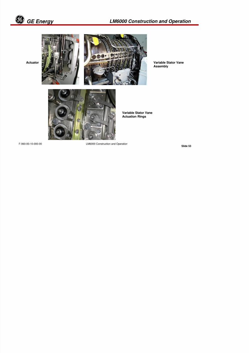
8/18/2019 71777896 - LM6000 Package Familiarization & Operations.pdf
http://slidepdf.com/reader/full/71777896-lm6000-package-familiarization-operationspdf 96/786
Slide 52
LM6000 Construction and OperationF-060-00-10-000-00
VARIABLE STATOR VANE ASSEMBLY
The VSV assembly, an integral part of the HPC stator, consists of two VSV
actuators and levers, actuation rings, and linkages for each VSV stage. Stator
vane position is vital to stable, efficient operation of the engine. While the HPC isdesigned for peak aerodynamic efficiency at full power and full speed, it mustalso operate at lower speeds. At these lower speeds, the later stages of thecompressor cannot consume all the air delivered by the earlier stages. The
variable stators accommodate this situation by limiting the compression ratio of
the first six stages of the compressor at low speeds and changing thecompression at higher speeds.
This is accomplished with two hydraulic actuators, one at the 3:00 o’clock
position and one at the 9:00 o’clock position. Each actuator uses an LVDT forposition feedback to the control system. The control system is designed to
provide excitation and signal conditioning for both LVDTs, and to control VSV
position by means of closed-loop scheduling of VSV actuator position, basedon corrected HP rotor speed (XN2.5R) and inlet temperature (T2.5).
LM6000 Construction and Operation GE Energyg

8/18/2019 71777896 - LM6000 Package Familiarization & Operations.pdf
http://slidepdf.com/reader/full/71777896-lm6000-package-familiarization-operationspdf 97/786
Slide 53
LM6000 Construction and OperationF-060-00-10-000-00
Variable Stator VaneAssembly
Variable Stator VaneActuation Rings
Actuator
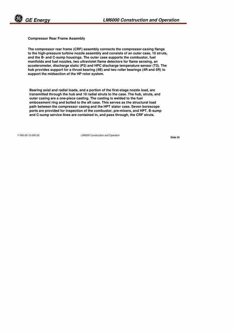
8/18/2019 71777896 - LM6000 Package Familiarization & Operations.pdf
http://slidepdf.com/reader/full/71777896-lm6000-package-familiarization-operationspdf 98/786
LM6000 Construction and Operation GE Energyg
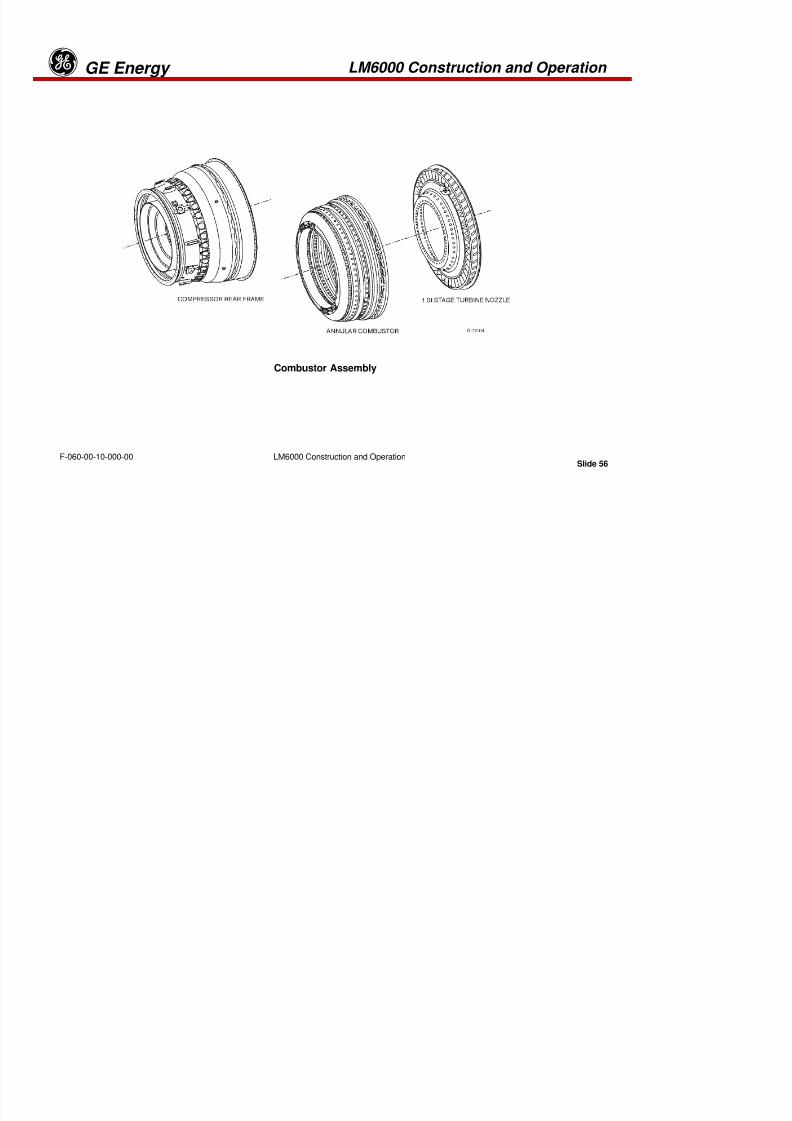
8/18/2019 71777896 - LM6000 Package Familiarization & Operations.pdf
http://slidepdf.com/reader/full/71777896-lm6000-package-familiarization-operationspdf 99/786
Slide 55
LM6000 Construction and OperationF-060-00-10-000-00
Compressor Rear Frame Assembly
The compressor rear frame (CRF) assembly connects the compressor-casing flange
to the high-pressure turbine nozzle assembly and consists of an outer case, 10 struts,
and the B- and C-sump housings. The outer case supports the combustor, fuel
manifolds and fuel nozzles, two ultraviolet flame detectors for flame sensing, anaccelerometer, discharge static (P3) and HPC discharge temperature sensor (T3). Thehub provides support for a thrust bearing (4B) and two roller bearings (4R and 5R) to
support the midsection of the HP rotor system.
Bearing axial and radial loads, and a portion of the first-stage nozzle load, aretransmitted through the hub and 10 radial struts to the case. The hub, struts, andouter casing are a one-piece casting. The casting is welded to the fuel
embossment ring and bolted to the aft case. This serves as the structural load
path between the compressor casing and the HPT stator case. Seven borescope
ports are provided for inspection of the combustor, pre-mixers, and HPT. B-sumpand C-sump service lines are contained in, and pass through, the CRF struts.
LM6000 Construction and Operation GE Energyg

8/18/2019 71777896 - LM6000 Package Familiarization & Operations.pdf
http://slidepdf.com/reader/full/71777896-lm6000-package-familiarization-operationspdf 100/786
Slide 56
LM6000 Construction and OperationF-060-00-10-000-00
Combustor Assembly
LM6000 Construction and Operation GE Energyg
Combustor Assembly
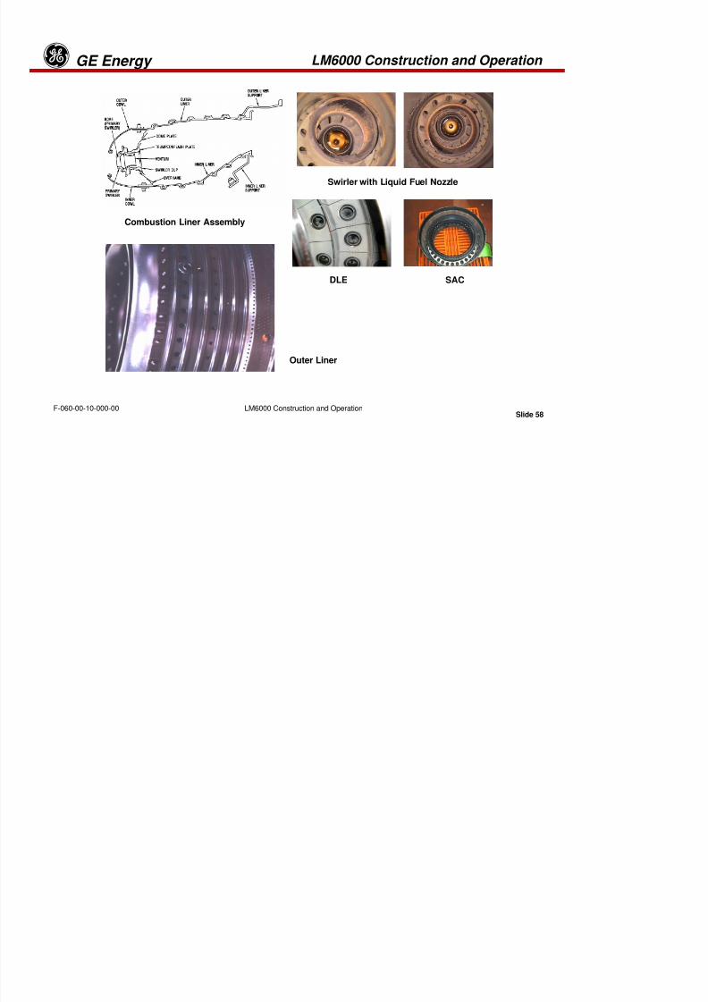
8/18/2019 71777896 - LM6000 Package Familiarization & Operations.pdf
http://slidepdf.com/reader/full/71777896-lm6000-package-familiarization-operationspdf 101/786
Slide 57LM6000 Construction and OperationF-060-00-10-000-00
The LM6000 gas turbine uses a singular annular combustor and is furnished with 30externally mounted fuel nozzles for liquid distillate fuel, natural gas fuel, or dual fuel,
depending upon the fuel system specified by the customer. Fuel systems may also
be equipped for water or steam injection for NOx suppression. This combustion
system is a high-performance design that has consistently demonstrated low exit
temperature pattern factors, low-pressure loss, low smoke, and high combustionefficiency at all operating conditions.
SINGULAR ANNULAR COMBUSTOR
Key features of the singular annular combustor are the rolled-ring inner and outerliners; the low-smoke emission, swirl-cup dome design and the short burning length.
The short burning length reduces liner cooling air consumption, which improves the
exit temperature pattern factor and profile. The swirl-cup dome design serves to lean-out the fuel-air mixture in the primary zone of the combustor. This eliminates the
formation of the high-carbon visible smoke that can result from over-rich burning inthis zone.
LM6000 Construction and Operation GE Energyg

8/18/2019 71777896 - LM6000 Package Familiarization & Operations.pdf
http://slidepdf.com/reader/full/71777896-lm6000-package-familiarization-operationspdf 102/786
Slide 58LM6000 Construction and OperationF-060-00-10-000-00
Combustion Liner Assembly
Swirler with Liquid Fuel Nozzle
SAC
Outer Liner
DLE
LM6000 Construction and Operation GE Energyg
Combustion Liner Assembly

8/18/2019 71777896 - LM6000 Package Familiarization & Operations.pdf
http://slidepdf.com/reader/full/71777896-lm6000-package-familiarization-operationspdf 103/786
Slide 59LM6000 Construction and OperationF-060-00-10-000-00
The combustion liner assembly is supported entirely at the aft end. The support ring onthe outer liner is trapped in a groove on the compressor rear frame (CRF) aft end with
the high pressure turbine case. The inner liner is supported by the inner flow path of the
CRF. The combustion assembly consists of an inner cowl, an outer cowl, a dome, andan inner and outer liner.
COWL
The cowl consists of 2 parts, the inner and outer cowls separated by the dome. Its
purpose is to form a smooth leading-edge which splits and meters the incoming airflow to the combustion assembly.
LM6000 Construction and Operation GE Energyg
DOME

8/18/2019 71777896 - LM6000 Package Familiarization & Operations.pdf
http://slidepdf.com/reader/full/71777896-lm6000-package-familiarization-operationspdf 104/786
Slide 60LM6000 Construction and OperationF-060-00-10-000-00
DOME
The dome is a fabricated component consisting of 30 vortex inducing swirlassemblies consisting of two counter--rotating primary and secondary swirlers.
Their purpose is to provide flame stabilization and complete mixing of the fuel air
mixture. The primary swirler floats on the face of the secondary swirler to allow
growth difference for the fuel nozzles. The entire surface of the dome is swept bya film of cooling air.
LINERS
The inner and outer liners are composed of a series of circumferentially rolled ringstrips joined together by resistance welding. They are protected from convectiveand radiant heat by continuous circumferential film cooling. Combustion zone
dilution and mixing air entry is provided by a pattern of various sized circular holes
in each ring. These holes provide recirculation for flame stabilization and
shape the exit gas profile. Ports and tube assemblies have been located at the 3:00and 5:00 o'clock positions for the igniter plugs. The liners and dome have a thermal
barrier coating applied to the hot side.
LM6000 Construction and Operation GE Energyg
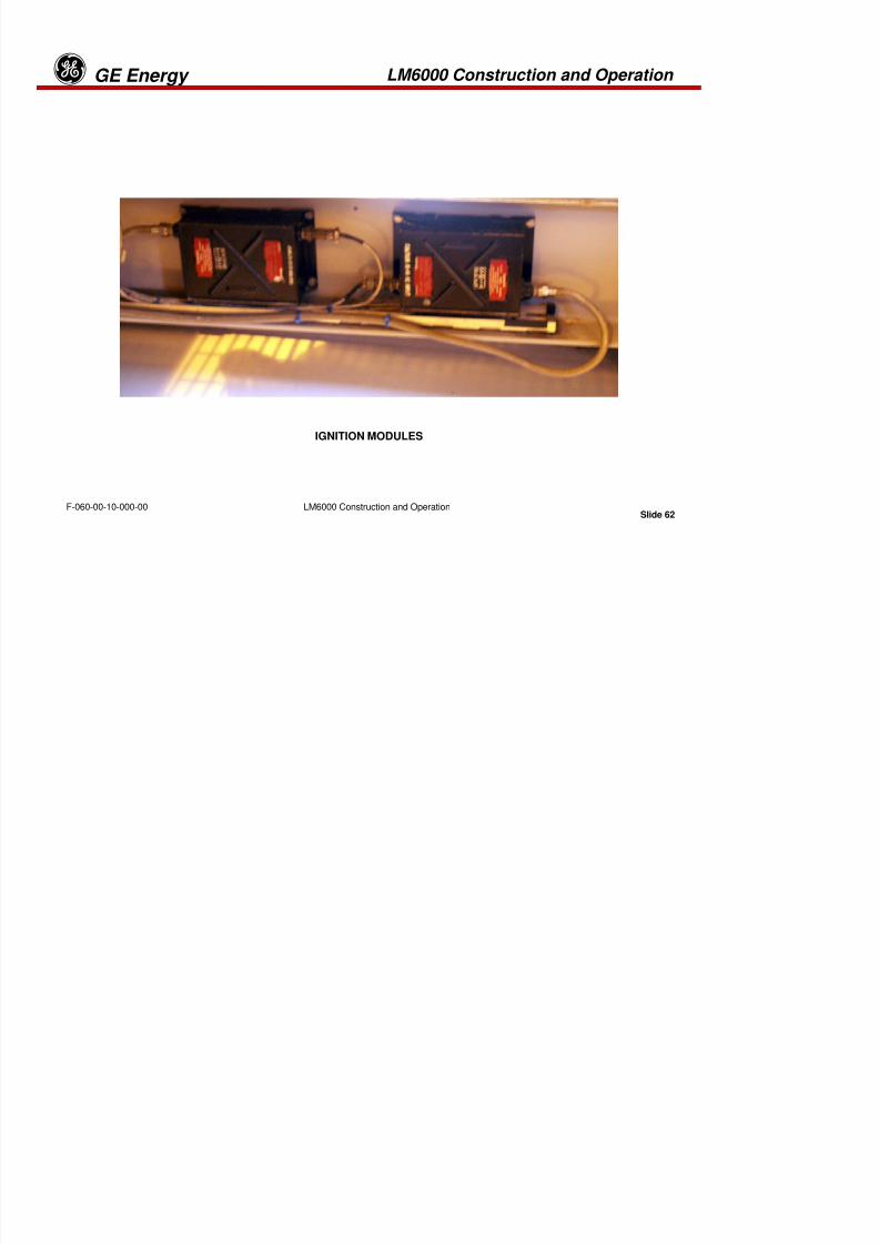
8/18/2019 71777896 - LM6000 Package Familiarization & Operations.pdf
http://slidepdf.com/reader/full/71777896-lm6000-package-familiarization-operationspdf 105/786
Slide 61LM6000 Construction and OperationF-060-00-10-000-00
IGNITION SYSTEM
The energy level of the ignition system is lethal, and personnelshould never contact output from the ignition exciters, leads origniter plugs.
LM6000 Construction and Operation GE Energyg

8/18/2019 71777896 - LM6000 Package Familiarization & Operations.pdf
http://slidepdf.com/reader/full/71777896-lm6000-package-familiarization-operationspdf 106/786
Slide 62LM6000 Construction and OperationF-060-00-10-000-00
IGNITION MODULES
LM6000 Construction and Operation GE Energyg
IGNITION SYSTEM
The ignition system produces the high-energy sparks that ignite the fuel-air mixture in

8/18/2019 71777896 - LM6000 Package Familiarization & Operations.pdf
http://slidepdf.com/reader/full/71777896-lm6000-package-familiarization-operationspdf 107/786
Slide 63LM6000 Construction and OperationF-060-00-10-000-00
The ignition system produces the high energy sparks that ignite the fuel air mixture inthe combustor during starting. The system consists of high-energy spark igniters, a
high-energy capacitor-discharge ignition exciter, and an interconnecting cable. The
ignition cables interconnect directly between the package-mounted exciters and the
igniters, which are mounted on the engine compressor rear frame.
During the start sequence, fuel is ignited by the igniter, which is energized by theignition exciter. Once combustion becomes self-sustaining, the igniter is de-energized
at ≥ 400 °°°°F (204 °°°°C).
Proper installation of the igniter plug on the combustion chamber is essential forlong operating life. The igniter plug has a special distance (packing) ring that mustbe installed between the plug and compressor rear frame. The correct distance of
the plug in the rear frame is important, both for operation and cooling, and it can beadjusted with the distance ring. Cooling is achieved with compressor air flowing
alongside the igniter plug tip. Also, 12 holes in the plug tip are present for cooling
purposes and, finally, 6 holes provide cooling air for the igniter plug shank.
LM6000 Construction and Operation GE Energyg

8/18/2019 71777896 - LM6000 Package Familiarization & Operations.pdf
http://slidepdf.com/reader/full/71777896-lm6000-package-familiarization-operationspdf 108/786
Slide 64LM6000 Construction and OperationF-060-00-10-000-00
The ignition system is normally energized only during the starting sequence. However,
the circuit should be arranged so that the ignition system can be manually operated formaintenance and testing.
To ensure a successful light off, the ignition system is comprised of two
independent ignition systems. Due to already increased air temperature fromcompression through the compressor, and fuel atomization from the fuel nozzle, it
is possible to achieve ignition with only one igniter. Running two independentsystems ensures the ability to maintain normal operations even with the completeloss of one system. Because of this configuration it is necessary to check the
operation of the igniter system on a routine basis in accordance with themaintenance work package.
LM6000 Construction and Operation GE Energyg
Typically the igniters should be checked when a turbine fails to light off and all other
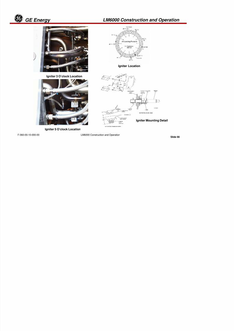
8/18/2019 71777896 - LM6000 Package Familiarization & Operations.pdf
http://slidepdf.com/reader/full/71777896-lm6000-package-familiarization-operationspdf 109/786
Slide 65LM6000 Construction and OperationF-060-00-10-000-00
Typically the igniters should be checked when a turbine fails to light-off and all other
primary start requirements are met. Such as:
•Proper acceleration of the HPC (XN2.5)
•Proper CDP pressure (P3)
•Proper fuel valve Position
This type of failure is due to loss of both igniters. The only igniter indication that the
operator can monitor is the logic state change on the Turbine Overview Screen. Theoperator screen change is a function of an energized relay coil. If there is a failure inthe ignition system, the screen may indicate proper operation but, in reality, the
system is inoperable. Because of the high voltage generated by the exciter module,there is no feedback of the igniter output to give a true indication of proper operation
of the circuit.
Duty cycle is:
90 seconds ON max, 2 start cycles in a 30 minute period
Power input is:
106-124 volt AC, Requirement at 60 Hz or 50 Hz
LM6000 Construction and Operation GE Energyg
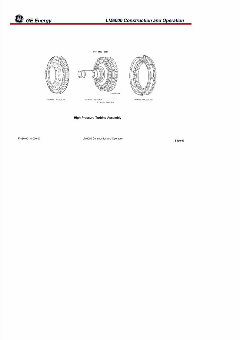
8/18/2019 71777896 - LM6000 Package Familiarization & Operations.pdf
http://slidepdf.com/reader/full/71777896-lm6000-package-familiarization-operationspdf 110/786
Slide 66LM6000 Construction and OperationF-060-00-10-000-00
Igniter Location
Igniter Mounting Detail
Igniter 3 O’clock Location
Igniter 5 O’clock Location
LM6000 Construction and Operation GE Energyg
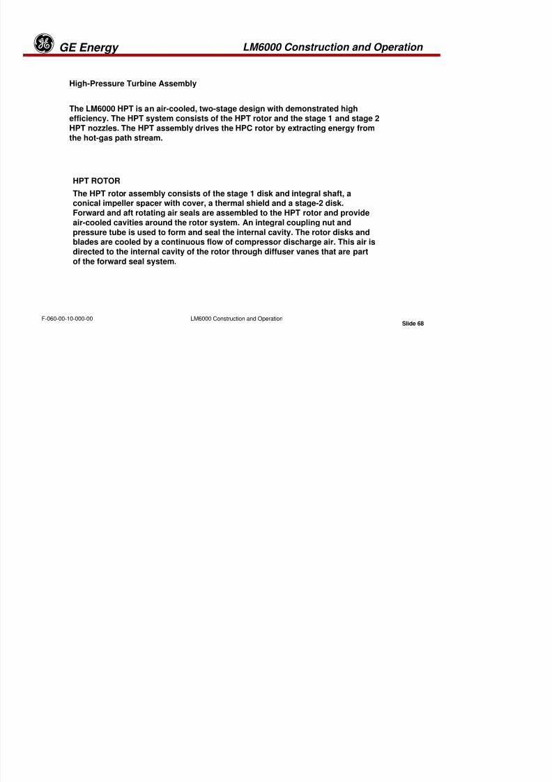
8/18/2019 71777896 - LM6000 Package Familiarization & Operations.pdf
http://slidepdf.com/reader/full/71777896-lm6000-package-familiarization-operationspdf 111/786
Slide 67LM6000 Construction and OperationF-060-00-10-000-00
High-Pressure Turbine Assembly
LM6000 Construction and Operation GE Energyg
High-Pressure Turbine Assembly

8/18/2019 71777896 - LM6000 Package Familiarization & Operations.pdf
http://slidepdf.com/reader/full/71777896-lm6000-package-familiarization-operationspdf 112/786
Slide 68LM6000 Construction and OperationF-060-00-10-000-00
The LM6000 HPT is an air-cooled, two-stage design with demonstrated highefficiency. The HPT system consists of the HPT rotor and the stage 1 and stage 2
HPT nozzles. The HPT assembly drives the HPC rotor by extracting energy from
the hot-gas path stream.
HPT ROTOR
The HPT rotor assembly consists of the stage 1 disk and integral shaft, a
conical impeller spacer with cover, a thermal shield and a stage-2 disk.Forward and aft rotating air seals are assembled to the HPT rotor and provide
air-cooled cavities around the rotor system. An integral coupling nut and
pressure tube is used to form and seal the internal cavity. The rotor disks andblades are cooled by a continuous flow of compressor discharge air. This air is
directed to the internal cavity of the rotor through diffuser vanes that are part
of the forward seal system.
LM6000 Construction and Operation GE Energyg
The stage 1 disk/shaft design combines the rotor forward shaft and stage 1 disk into

8/18/2019 71777896 - LM6000 Package Familiarization & Operations.pdf
http://slidepdf.com/reader/full/71777896-lm6000-package-familiarization-operationspdf 113/786
Slide 69LM6000 Construction and OperationF-060-00-10-000-00
a one-piece unit. Torque is transmitted to the compressor rotor through an internalspline at the forward end of the disk/shaft. The stage 1 blades fit into axial dovetail
slots in the disk. The stage 2 disk incorporates a flange on the forward side for
transmitting torque to the stage 1 disk. An aft flange supports the aft air seal and the
integral coupling nut and pressure tube. Stage 2 blades fit into axial dovetail slots inthe disk.
Internally cooled turbine blades are used in both stages. Both stages of blades are
cooled by compressor discharge air flowing through the blade shank into the airfoil.
The cone-shaped impeller spacer serves as the structural support between the turbine
disks. The spacer also transmits torque from the stage 2 disk to the stage 1 disk. The
catenary-shaped thermal shield forms the outer portion of the turbine rotor cooling aircavity and serves as the rotating portion of the interstage gas path seal.
LM6000 Construction and Operation GE Energyg

8/18/2019 71777896 - LM6000 Package Familiarization & Operations.pdf
http://slidepdf.com/reader/full/71777896-lm6000-package-familiarization-operationspdf 114/786
Slide 70LM6000 Construction and OperationF-060-00-10-000-00
High-Pressure Turbine Blade Cooling
LM6000 Construction and Operation GE Energyg
Stage 1 HPT Nozzle—The stage 1 HPT nozzle consists of 23 two-vane segments bolted
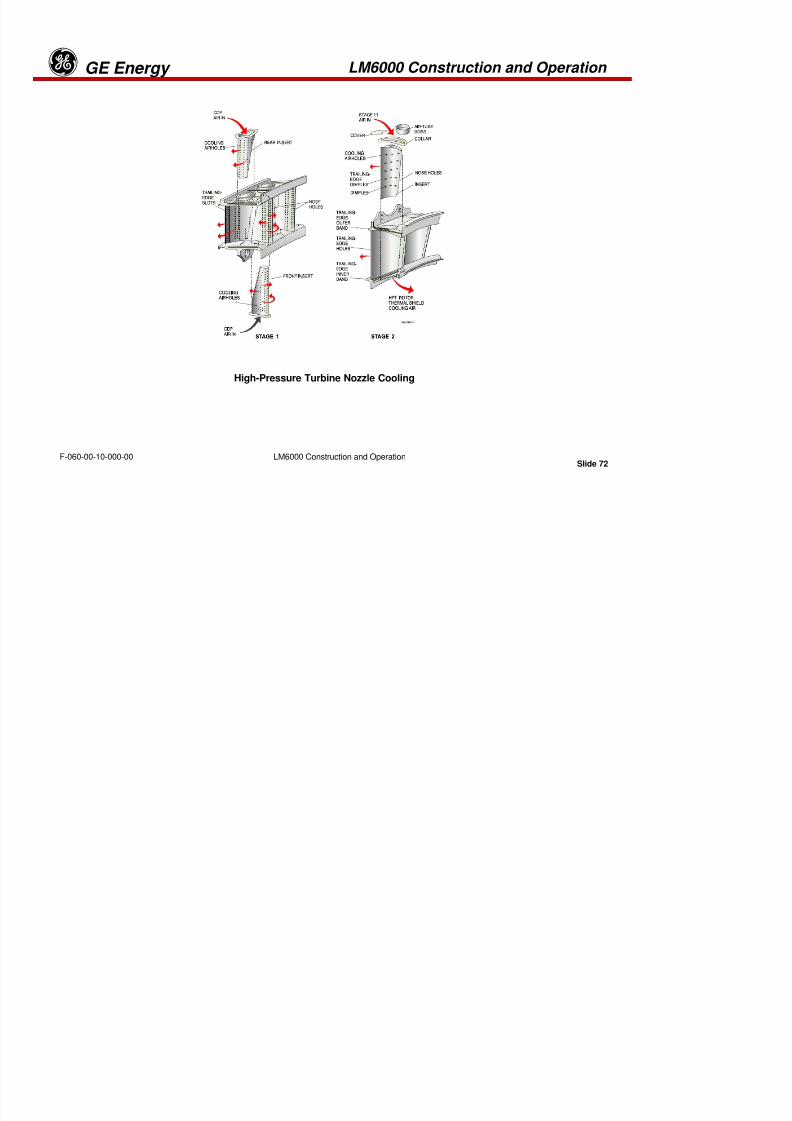
8/18/2019 71777896 - LM6000 Package Familiarization & Operations.pdf
http://slidepdf.com/reader/full/71777896-lm6000-package-familiarization-operationspdf 115/786
Slide 71LM6000 Construction and OperationF-060-00-10-000-00
High-Pressure Turbine Blade Cooling
Stage 1 High-Pressure Turbine Blades—First-stage turbine blades, contained withinthe CRF, are internally cooled with HPC discharge air. The HPC discharge air is
directed through the turbine disk to the blade roots, passing through inlet holes in the
shank to serpentine passages within the airfoil section of the blade. This air finally
exits through nose and gill holes in the leading edge of the blades, where it forms an
insulating film over the airfoil surface through holes in the cap at the outer end of theblade and through holes in the trailing edge of the airfoil.
Stage 2 High-Pressure Turbine Blades—Because the hot-gas path stream is cooler
when it reaches the second-stage turbine blades, the cooling required to maintain a
suitable metal temperature is not as great as with the first stage. The second-stageblades are, therefore, only cooled by convection. The air moves through passages
within the airfoil section and is discharged only at the blade tips.
Stage 1 HPT Nozzle—The stage 1 HPT nozzle consists of 23 two-vane segments boltedto a nozzle support attached to the hub of the CRF.
LM6000 Construction and Operation GE Energyg
8/18/2019 71777896 - LM6000 Package Familiarization & Operations.pdf
http://slidepdf.com/reader/full/71777896-lm6000-package-familiarization-operationspdf 116/786
Slide 72LM6000 Construction and OperationF-060-00-10-000-00
High-Pressure Turbine Nozzle Cooling
LM6000 Construction and Operation GE Energyg
High-Pressure Turbine Nozzle CoolingCompressor discharge air is used to cool the nozzle vanes and support bands to maintainthe metal temperatures at the levels required for extended operating life Stage 11-

8/18/2019 71777896 - LM6000 Package Familiarization & Operations.pdf
http://slidepdf.com/reader/full/71777896-lm6000-package-familiarization-operationspdf 117/786
Slide 73LM6000 Construction and OperationF-060-00-10-000-00
the metal temperatures at the levels required for extended operating life. Stage 11-
discharge air enters at the top and bottom of each vane. The air cools the vanes internally,
and is then discharged through a large number of small holes and slots strategically
located so the air forms an insulating film over the entire surface of the vanes.
Stage 2 HPT Nozzle—The stage 2 HPT nozzle assembly consists of stage 2 nozzle
segments, stages 1 and 2 HPT shrouds and shroud supports, HPT stator support (case),and interstage seals. There are 24 paired nozzle-vane segments. The nozzle vanes areinternally cooled by HPC Stage 11 air.
The stage 2 nozzles are supported by the stage 1 shroud support. They are also bolted to
the stage 2 shroud support forward leg, which is attached by a flange to the outerstructural wall. The stage 1 shroud system features segmented supports and shroud
segments to maintain turbine clearance.
The turbine shrouds form a portion of the outer aerodynamic flow path through theturbine. They are axially aligned with the turbine blades and form a pressure seal to
minimize HP gas leakage around the tips of the blades.
LM6000 Construction and Operation GE Energyg

8/18/2019 71777896 - LM6000 Package Familiarization & Operations.pdf
http://slidepdf.com/reader/full/71777896-lm6000-package-familiarization-operationspdf 118/786
Slide 74LM6000 Construction and OperationF-060-00-10-000-00
HPT Interstage Seal
LM6000 Construction and Operation GE Energyg
8/18/2019 71777896 - LM6000 Package Familiarization & Operations.pdf
http://slidepdf.com/reader/full/71777896-lm6000-package-familiarization-operationspdf 119/786
Slide 75LM6000 Construction and OperationF-060-00-10-000-00
Low-Pressure Turbine Assembly
LM6000 Construction and Operation GE Energyg
Low-Pressure Turbine Assembly
The LPT drives the LPC and load device using the core gas turbine discharge gas

8/18/2019 71777896 - LM6000 Package Familiarization & Operations.pdf
http://slidepdf.com/reader/full/71777896-lm6000-package-familiarization-operationspdf 120/786
Slide 76LM6000 Construction and OperationF-060-00-10-000-00
The LPT drives the LPC and load device using the core gas turbine discharge gas
flow for energy. The principal components of the LPT module are a five-stage stator,
a five-stage rotor supported by the No. 6R and No. 7R bearings, and a cast Turbine
Rear Frame (TRF) supporting the stator casing and the No. 6R and No. 7R bearings.
LPT ROTOR
The LPT rotor assembly drives the LPC through the LP mid-shaft and drives a load
through either the mid-shaft or from an aft drive adapter on the rear of the LPT rotor.
The LPT rotor assembly consists of five stages of bladed disks and a shaft sub-
assembly. The rotor is supported by the No. 6R and No. 7R bearings in the D and Esump of the TRF.
LM6000 Construction and Operation GE Energyg
Each LPT rotor stage consists of a bladed disk subassembly that is comprised of
a disk, turbine blades, and blade retainers, interstage air seals, assembly bolts,
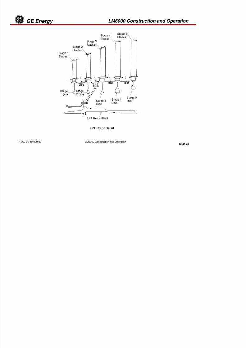
8/18/2019 71777896 - LM6000 Package Familiarization & Operations.pdf
http://slidepdf.com/reader/full/71777896-lm6000-package-familiarization-operationspdf 121/786
Slide 77LM6000 Construction and OperationF-060-00-10-000-00
, , , g , y ,and balance weights. Integral flanges on each disk provide assembly bolt holes in
a low-stress area of the disk. Blade retainers hold the turbine blades in the axial
dovetail slots.
The turbine shaft assembly is a torque cone coupled to the mid-shaft through a
spline and is bolted to the stage 2 and stage 3 turbine disk flanges. It alsoprovides the journal for the D- and E-sump air/oil seal and the No. 6R and No. 7R
bearing interfaces. The rotating portion of the balance piston system mounts onthe shaft aft of the No. 7R bearing seals. Additionally, the aft shaft spline provides
for driving the output load from the rear through the aft drive adapter.
LM6000 Construction and Operation GE Energyg

8/18/2019 71777896 - LM6000 Package Familiarization & Operations.pdf
http://slidepdf.com/reader/full/71777896-lm6000-package-familiarization-operationspdf 122/786
Slide 78LM6000 Construction and OperationF-060-00-10-000-00
LPT Rotor Detail
LM6000 Construction and Operation GE Energyg
LPT NOZZLES
The five-stage stator assembly consists of a one-piece tapered 360° casing, five stagesof interlocking tip shrouds, and a 12-segment LPT case external cooling manifold. Air-
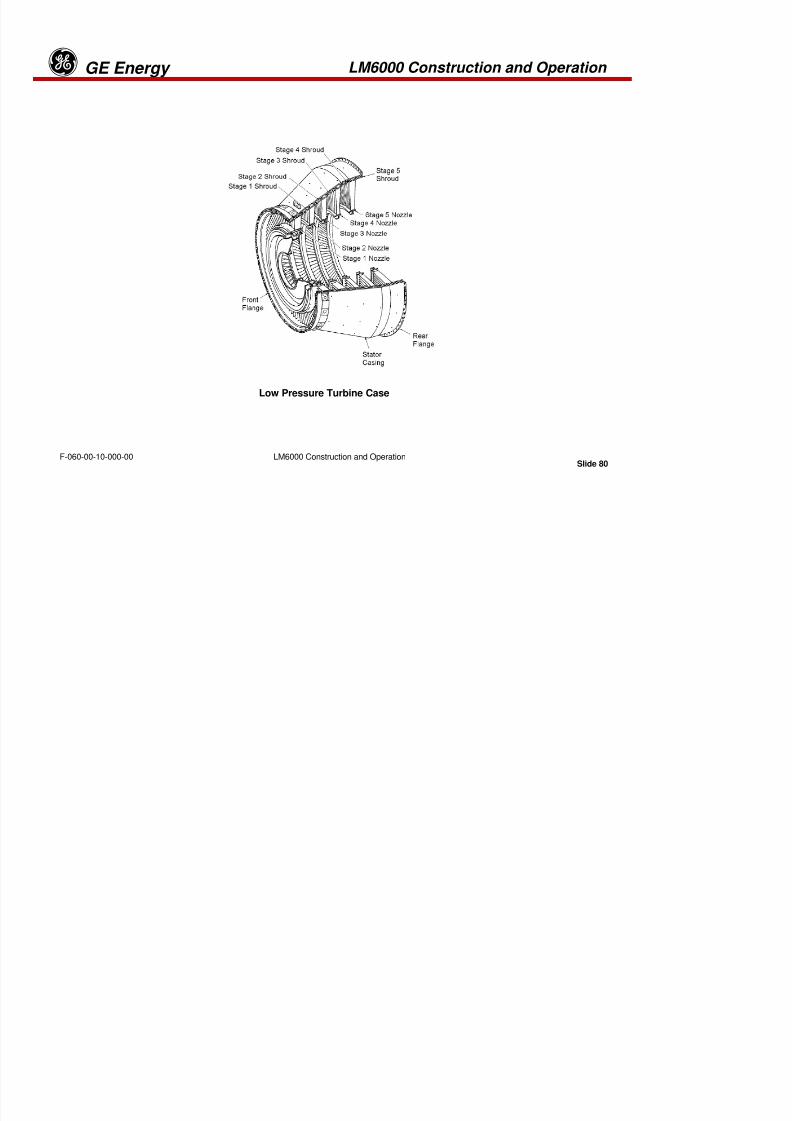
8/18/2019 71777896 - LM6000 Package Familiarization & Operations.pdf
http://slidepdf.com/reader/full/71777896-lm6000-package-familiarization-operationspdf 123/786
Slide 79LM6000 Construction and OperationF-060-00-10-000-00
o te oc g t p s ouds, a d a seg e t case e te a coo g a o dcooled, first-stage nozzle segments with a bolt-on pressure balance seal, four
additional stages of nozzle segments with bolt-on inter-stage seals, and
instrumentation and borescope ports also make up the stator assembly.
First stage nozzle cooling air is supplied from the 8th stage HPC bleed air header and highpressure recoup air.
The LPT casing is the load-carrying structure between the HPT stator case and the TRF.The casing contains internal machined flanges that provide hooks to support the nozzle
segments and stops to assure nozzle alignment and seating. Borescope inspection portsare provided along the right side, aft looking forward (ALF) from the 2:30 to 4:30 positions
at nozzle stages 1, 2, and 4.
LM6000 Construction and Operation GE Energyg
8/18/2019 71777896 - LM6000 Package Familiarization & Operations.pdf
http://slidepdf.com/reader/full/71777896-lm6000-package-familiarization-operationspdf 124/786
Slide 80LM6000 Construction and OperationF-060-00-10-000-00
Low Pressure Turbine Case
LM6000 Construction and Operation GE Energyg
Low Pressure Turbine Case
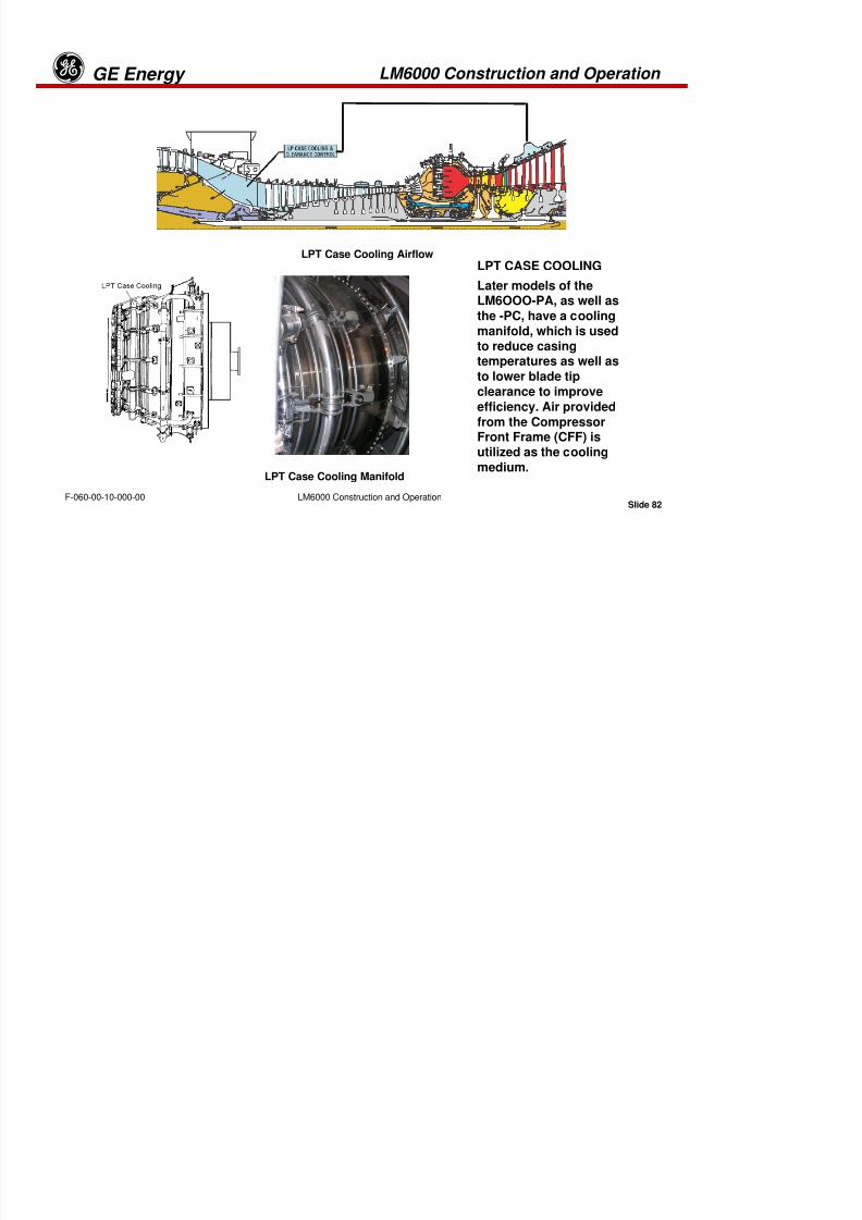
8/18/2019 71777896 - LM6000 Package Familiarization & Operations.pdf
http://slidepdf.com/reader/full/71777896-lm6000-package-familiarization-operationspdf 125/786
Slide 81LM6000 Construction and OperationF-060-00-10-000-00
The stage 1-nozzle vanes provide capability for LPT inlet instrumentation. Eight
separate shielded chromel-alumel (type K) thermocouple probes are installed on
the LPT stator case to sense LPT inlet temperature. Each dual-element T4.8 sensor
reads an average of the two elements for a total of eight control readings. Twoflexible harnesses, each connected to four of the probes, are routed to connectorson the No. 4 electrical panel. The engine also has an LPT inlet gas total pressure
(P4.8) probe located on the right side of the LPT stator case. Seals minimize the air
leakage around the inner ends of the nozzles, and shrouds minimize air leakageover the tips of the turbine blades
LM6000 Construction and Operation GE Energyg
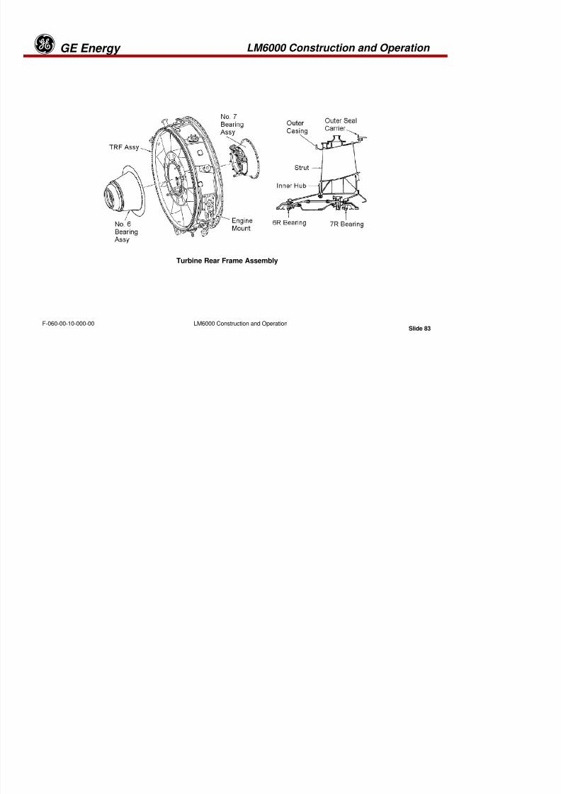
8/18/2019 71777896 - LM6000 Package Familiarization & Operations.pdf
http://slidepdf.com/reader/full/71777896-lm6000-package-familiarization-operationspdf 126/786
Slide 82LM6000 Construction and OperationF-060-00-10-000-00
LPT Case Cooling Manifold
LPT Case Cooling AirflowLPT CASE COOLING
Later models of theLM6OOO-PA, as well as
the -PC, have a coolingmanifold, which is usedto reduce casingtemperatures as well as
to lower blade tip
clearance to improve
efficiency. Air provided
from the CompressorFront Frame (CFF) isutilized as the cooling
medium.
LM6000 Construction and Operation GE Energyg
8/18/2019 71777896 - LM6000 Package Familiarization & Operations.pdf
http://slidepdf.com/reader/full/71777896-lm6000-package-familiarization-operationspdf 127/786
Slide 83LM6000 Construction and OperationF-060-00-10-000-00
Turbine Rear Frame Assembly
LM6000 Construction and Operation GE Energyg
Turbine Rear Frame AssemblyThe turbine rear frame (TRF) is a one-piece casting that provides the gasturbine exhaust flow path and the supporting structure for the D and E
sump the LPT rotor thrust balance assembly the LPT rotor shaft and the
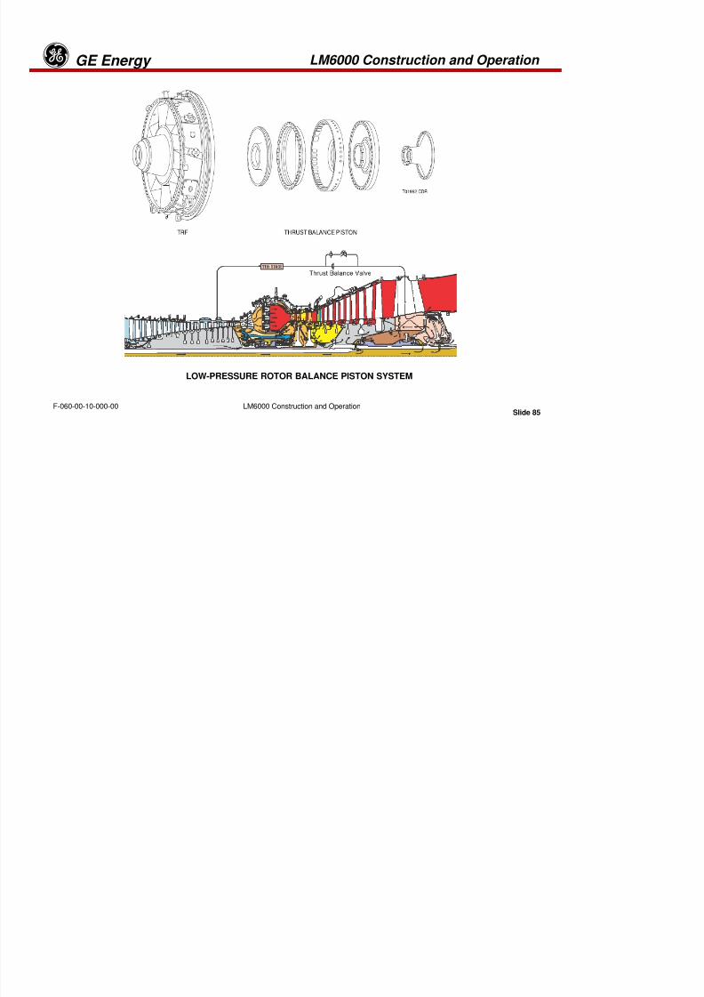
8/18/2019 71777896 - LM6000 Package Familiarization & Operations.pdf
http://slidepdf.com/reader/full/71777896-lm6000-package-familiarization-operationspdf 128/786
Slide 84LM6000 Construction and OperationF-060-00-10-000-00
sump, the LPT rotor thrust balance assembly, the LPT rotor shaft, and the
aft drive adapter. Fourteen radial struts function as outlet guide vanes to
straighten the exhaust airflow into the exhaust diffuser for enhanced
performance. Lubrication oil supply and scavenge lines for the D and Esump and LPT rotor speed sensors (XNSD-A and XNSD-B) are routedthrough the struts.
The LPT rotor thrust balance system is designed to maintain the axial
thrust loading on the No. 1B thrust bearing within design limits. Thebalance piston static seal is mounted to the TRF hub. Stage 11 HPC
bleed air is routed through three TRF struts to generate the required
axial loading through the rotor thrust balance system.
LM6000 Construction and Operation GE Energyg
8/18/2019 71777896 - LM6000 Package Familiarization & Operations.pdf
http://slidepdf.com/reader/full/71777896-lm6000-package-familiarization-operationspdf 129/786
Slide 85LM6000 Construction and OperationF-060-00-10-000-00
LOW-PRESSURE ROTOR BALANCE PISTON SYSTEM
LM6000 Construction and Operation GE Energyg
LOW-PRESSURE ROTOR BALANCE PISTON SYSTEM
A balance piston system has been included in the aft-end of the engine to control
thrust loading on the No. 1B bearing. These loads are imposed by LPC and LPT

8/18/2019 71777896 - LM6000 Package Familiarization & Operations.pdf
http://slidepdf.com/reader/full/71777896-lm6000-package-familiarization-operationspdf 130/786
Slide 86LM6000 Construction and OperationF-060-00-10-000-00
g g p y
and vary with output power. Forward axial loads are applied by varying air
pressure in the balance piston air cavity to maintain thrust loads within the
capability of the bearing.
In earlier systems, balance piston pressurization air from the 11th stage high pressure
compressor was controlled by an electrically operated, hydraulically actuated controlvalve called a thrust balance valve. Hydraulic fluid for valve actuation is supplied from
the variable geometry hydraulic control unit. A bypass line with orifice was supplied toensure positive balance piston pressure in case of valve failure. Current LM6000
production units are supplied with orifice only for supply of 11th stage bleed air to thebalance piston.
The balance piston system consists of the balance piston disk, the balance piston casing,
their associated seals, and the dome-shaped cavity formed by these parts. This cavity ispressurized by stage 11 HPC bleed air. The balance piston casing is attached to the aft-inner
hub of the TRF; the balance piston disk is attached to the LPT shaft. Thrust is monitored by a
total-pressure probe (P48) and static-pressure probe (PS55).

8/18/2019 71777896 - LM6000 Package Familiarization & Operations.pdf
http://slidepdf.com/reader/full/71777896-lm6000-package-familiarization-operationspdf 131/786
LM6000 Construction and Operation GE Energyg
Accessory Gearbox
Engine starting, lubrication, and speed monitoring of the HP rotor shaft areli h d b i t d th g b (AGB)

8/18/2019 71777896 - LM6000 Package Familiarization & Operations.pdf
http://slidepdf.com/reader/full/71777896-lm6000-package-familiarization-operationspdf 132/786
Slide 88LM6000 Construction and OperationF-060-00-10-000-00
accomplished by accessories mounted on the accessory gearbox (AGB).
The following accessories are mounted on the AGB:
• Hydraulic starting motor
• Clutch assembly
• Variable-geometry control unit
• Engine lube oil pump
• Fuel-metering valve hydraulic oil pump (optional)
• Two magnetic speed pickups (XN25-A and XN25-B)
• Transfer gearbox
• Radial drive shaft
The AGB is mounted beneath the gas generator at the compressor’s front frame.Fitted to the aft side of the gearbox is the hydraulic starting motor clutch, whichdrives the transfer gearbox, radial drive shaft, and inlet gearbox in A-sump to rotate
the HPC rotor.
LM6000 Construction and Operation GE EnergygENGINE AIRFLOW

8/18/2019 71777896 - LM6000 Package Familiarization & Operations.pdf
http://slidepdf.com/reader/full/71777896-lm6000-package-familiarization-operationspdf 133/786
Slide 89LM6000 Construction and OperationF-060-00-10-000-00
LM6000 Construction and Operation GE Energyg
ENGINE AIRFLOW
Air enters the engine at the inlet of the variable inlet guide vanes (VIGVs) and passesinto the low-pressure compressor (LPC). The low-pressure compressor compresses the
air by a ratio of approximately 2 4:1 Air leaving the low pressure compressor is

8/18/2019 71777896 - LM6000 Package Familiarization & Operations.pdf
http://slidepdf.com/reader/full/71777896-lm6000-package-familiarization-operationspdf 134/786
Slide 90LM6000 Construction and OperationF-060-00-10-000-00
air by a ratio of approximately 2.4:1. Air leaving the low-pressure compressor isdirected into the high-pressure compressor (HPC) and is regulated at idle and low
power by variable bypass valves (VBVs) arranged in the flow passage between the two
compressors.
The hot gases from combustion are then directed into the HPT, which drives HPC. The
exhaust gases exit the HPT and enter the low-pressure turbine (LPT), which drives both theLPC and the output load. The exhaust gases pass through the LPT and exit through the
exhaust duct.
Air entering the combustor is mixed with the fuel and ignited. Once combustionbecomes self-sustaining, the igniter is de-energized. The combustion gases then exitto the high-pressure turbine (HPT).
The airflow in the 14-stage HPC is regulated by VIGVs and five stages of variable
stator vanes (VSVs). The HPC compression ratio is approximately 12:1. HPCdischarge and stage 8 bleed air are extracted, as necessary, for emissions control.
Compressor discharge air is then directed to the combustor section.
LM6000 Construction and Operation GE Energyg

8/18/2019 71777896 - LM6000 Package Familiarization & Operations.pdf
http://slidepdf.com/reader/full/71777896-lm6000-package-familiarization-operationspdf 135/786
Slide 91LM6000 Construction and OperationF-060-00-10-000-00
Low Pressure Compressor Discharge Usage
LM6000 Construction and Operation GE Energyg

8/18/2019 71777896 - LM6000 Package Familiarization & Operations.pdf
http://slidepdf.com/reader/full/71777896-lm6000-package-familiarization-operationspdf 136/786
Slide 92LM6000 Construction and OperationF-060-00-10-000-00
Compressor Discharge Pressure Usage
LM6000 Construction and Operation GE EnergygTURBINE INSTRUMENTATION
AGB Accessory GearboxCDF Compressor Rear FrameIGV Inlet Guide VaneLVDT Linear Variable Differential TransducerRTD Resistance Temperature Detector
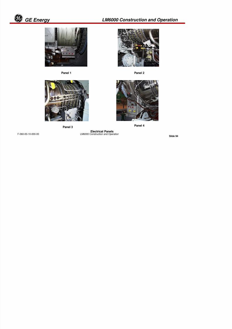
8/18/2019 71777896 - LM6000 Package Familiarization & Operations.pdf
http://slidepdf.com/reader/full/71777896-lm6000-package-familiarization-operationspdf 137/786
Slide 93LM6000 Construction and OperationF-060-00-10-000-00
RTD Resistance Temperature DetectorTC ThermocoupleTM Torque MotorTGB Transfer GearboxTRF Turbine Rear Frame
T4.8 Low Pressure Turbine Entry TemperatureT2 Low Pressure Compressor Inlet TemperatureT2.5 Low Pressure Compressor Discharge TemperatureT3 High Pressure Compressor Discharge TemperatureVBV Variable Bypass VaneVSV Variable Stator VaneXNSD Low Pressure Turbine Rotor SpeedXN2 Low Pressure Rotor SpeedXN25 High Pressure Rotor Speed
LM6000 Electrical Cable Panel Nomenclature
Cabling
The LM6000 Is supplied with electrical cables for interconnection between
package mounted junction boxes and the engine. Each of the cablesconnects the engine at 1 of 4 electrical panels. Instrumentation leads areisolated from power leads, shielded, and run in conduits carrying only other
very low level leads.
LM6000 Construction and Operation GE Energyg
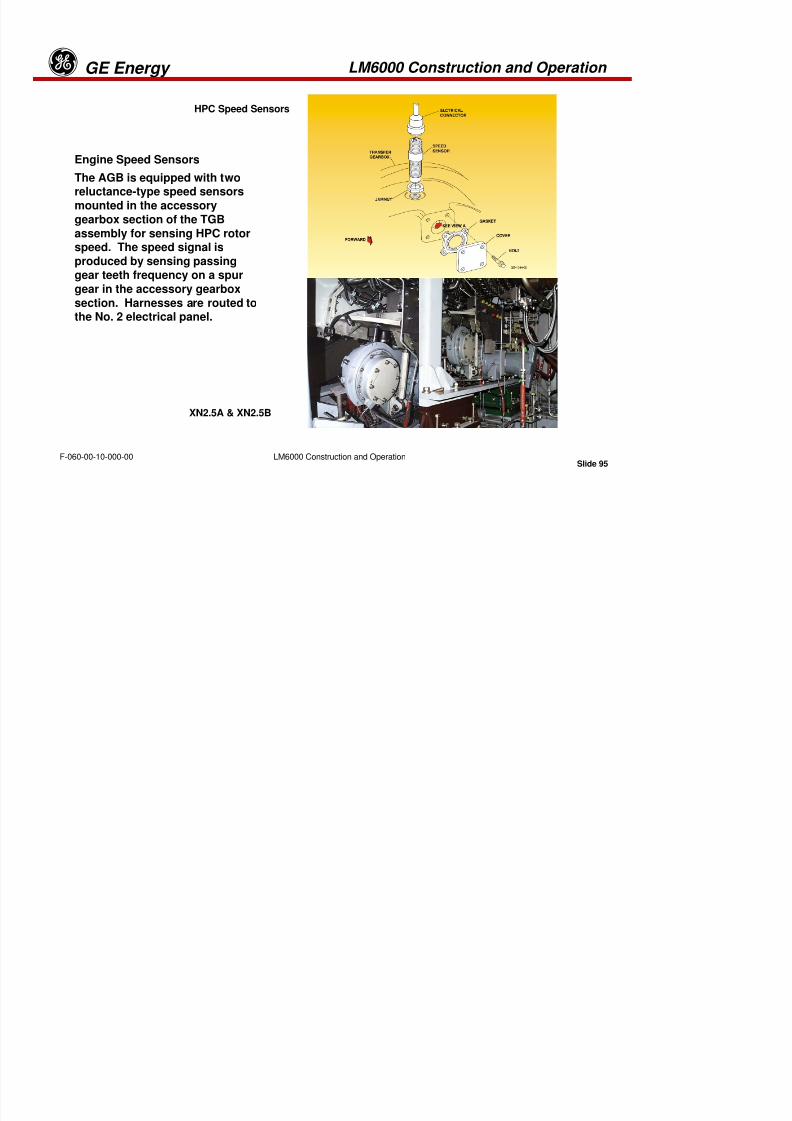
8/18/2019 71777896 - LM6000 Package Familiarization & Operations.pdf
http://slidepdf.com/reader/full/71777896-lm6000-package-familiarization-operationspdf 138/786
Slide 94LM6000 Construction and OperationF-060-00-10-000-00
Electrical Panels
Panel 1 Panel 2
Panel 3Panel 4
LM6000 Construction and Operation GE EnergygHPC Speed Sensors
Engine Speed Sensors
The AGB is equipped with two

8/18/2019 71777896 - LM6000 Package Familiarization & Operations.pdf
http://slidepdf.com/reader/full/71777896-lm6000-package-familiarization-operationspdf 139/786
Slide 95LM6000 Construction and OperationF-060-00-10-000-00
XN2.5A & XN2.5B
The AGB is equipped with tworeluctance-type speed sensors
mounted in the accessorygearbox section of the TGB
assembly for sensing HPC rotorspeed. The speed signal is
produced by sensing passinggear teeth frequency on a spur
gear in the accessory gearbox
section. Harnesses are routed tothe No. 2 electrical panel.
LM6000 Construction and Operation GE EnergygLow-Pressure Turbine
Speed Sensor
Low-Pressure Turbine Speed
Sensor

8/18/2019 71777896 - LM6000 Package Familiarization & Operations.pdf
http://slidepdf.com/reader/full/71777896-lm6000-package-familiarization-operationspdf 140/786
Slide 96LM6000 Construction and OperationF-060-00-10-000-00
XNSD
(Left and Right Side)
Sensor
The LPT is equipped with 2
reluctance-type sensors,mounted in the turbine rear
frame at strut Nos. 2 and 9.These sensors detect and
measure the tooth-passing
frequency of a toothed
sensor ring attached to theLPT rotor shaft. Eachsensor has an integral lead
which terminates on the No.
4 electrical panel. XNSD (Left
and Right Side)
LM6000 Construction and Operation GE EnergygEngine Vibration Sensors
Vibration Sensors
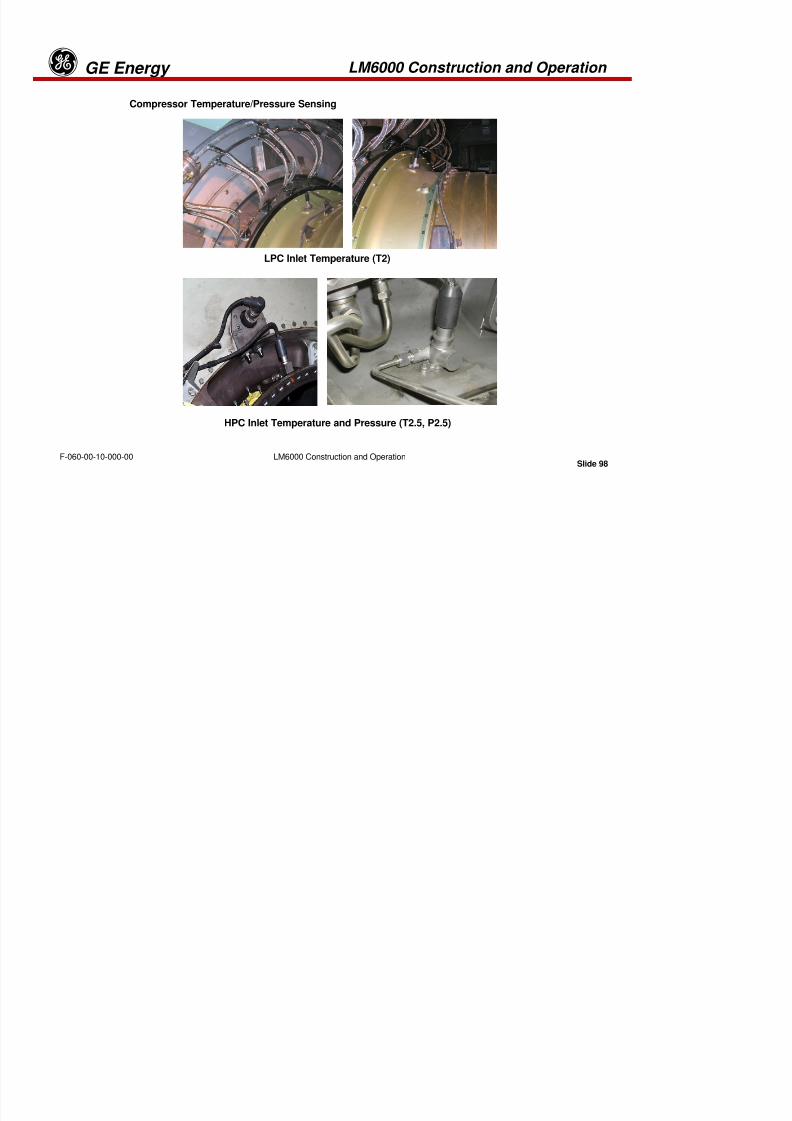
8/18/2019 71777896 - LM6000 Package Familiarization & Operations.pdf
http://slidepdf.com/reader/full/71777896-lm6000-package-familiarization-operationspdf 141/786
Slide 97LM6000 Construction and OperationF-060-00-10-000-00
(Close-up)
Accelerometer
Mounting at CRF
The engine is equipped with twoaccelerometers, one on the CRF andone on the TRF. These accelerometers
provide protection against self-induced
synchronous vibration. Each sensor iscapable of monitoring both high-speed
and low-speed rotor vibration levels.
Each accelerometer sensor has an
integral lead that is routed to one of theelectrical panels: CRF accelerometer tothe No. 3 electrical panel and TRF
accelerometer to the No.4 electrical
panel.
8/18/2019 71777896 - LM6000 Package Familiarization & Operations.pdf
http://slidepdf.com/reader/full/71777896-lm6000-package-familiarization-operationspdf 142/786
LM6000 Construction and Operation GE Energyg
LPC Inlet Temperature (T2)
The engine is equipped with a probe to measure the LPC inlet temperature(T2). The probe contains a dual element, Resistance-Temperature Detector
(RTD) i h i l l d i i h N 1 l i l l Th

8/18/2019 71777896 - LM6000 Package Familiarization & Operations.pdf
http://slidepdf.com/reader/full/71777896-lm6000-package-familiarization-operationspdf 143/786
Slide 99LM6000 Construction and OperationF-060-00-10-000-00
(RTD) with an integral lead terminating at the No. 1 electrical panel. The
probe is located in the IGV/VIGV case which contains provisions for a
second optional probe.
HPC Inlet Temperature and Pressure (T2.5, P2.5)
HPC Inlet Temperature and Pressure (T2.5, P2.5)
The engine is equipped with a probe to measure the HPC inlet totaltemperature (T2.5) the inlet total pressure (P2.5) of the HPC. The probe
contains a dual-element Resistance-Temperature Detector (RTD) with an
integral lead terminating at the No.2 electrical panel.
LM6000 Construction and Operation GE Energyg
HP Compressor Discharge Temperature (T3)
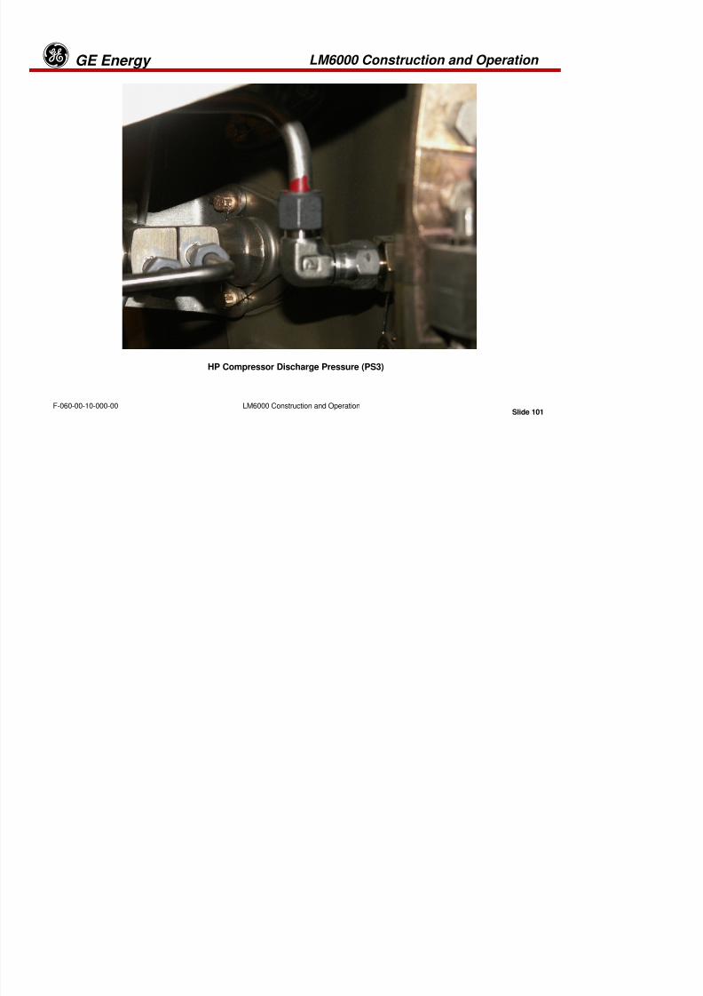
8/18/2019 71777896 - LM6000 Package Familiarization & Operations.pdf
http://slidepdf.com/reader/full/71777896-lm6000-package-familiarization-operationspdf 144/786
Slide 100LM6000 Construction and OperationF-060-00-10-000-00
LM6000 Construction and Operation GE Energyg
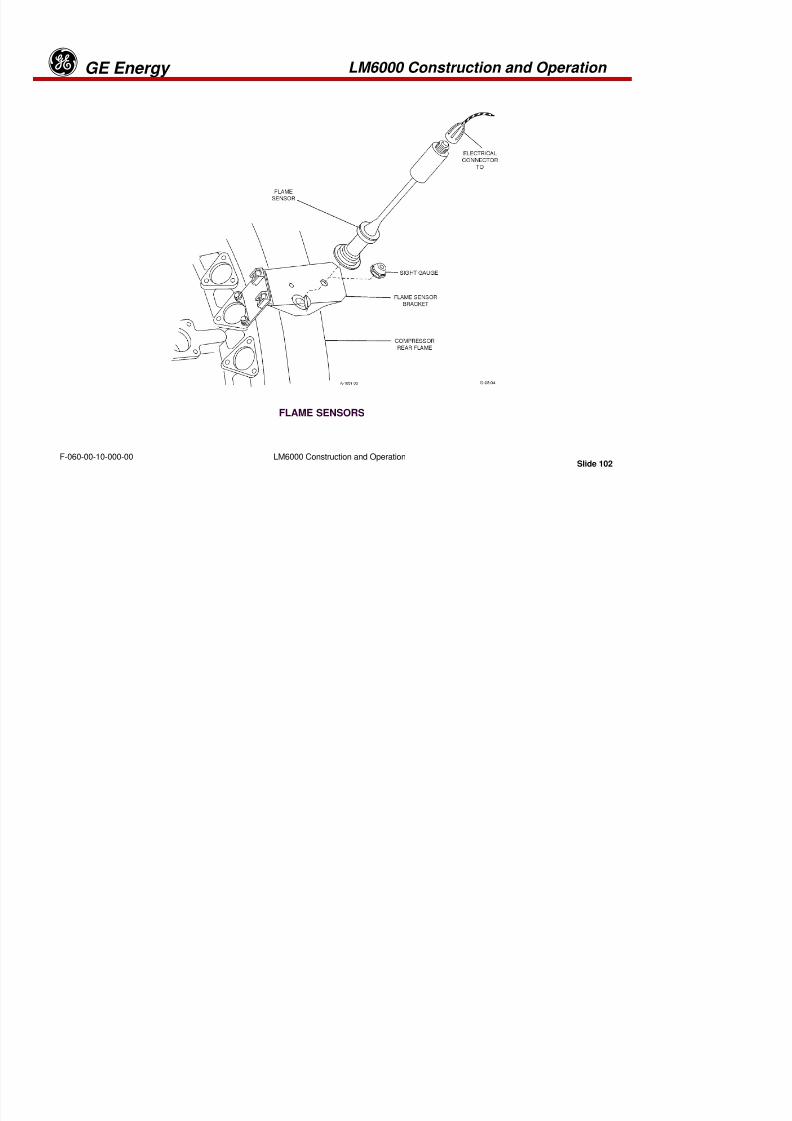
8/18/2019 71777896 - LM6000 Package Familiarization & Operations.pdf
http://slidepdf.com/reader/full/71777896-lm6000-package-familiarization-operationspdf 145/786
Slide 101LM6000 Construction and OperationF-060-00-10-000-00
HP Compressor Discharge Pressure (PS3)
LM6000 Construction and Operation GE Energyg
8/18/2019 71777896 - LM6000 Package Familiarization & Operations.pdf
http://slidepdf.com/reader/full/71777896-lm6000-package-familiarization-operationspdf 146/786
Slide 102LM6000 Construction and OperationF-060-00-10-000-00
FLAME SENSORS
LM6000 Construction and Operation GE Energyg
FLAME SENSORS
An ultraviolet flame sensor detects the presence or loss of flame in the engine combustionsystem for control system logic use in sequencing and monitoring.

8/18/2019 71777896 - LM6000 Package Familiarization & Operations.pdf
http://slidepdf.com/reader/full/71777896-lm6000-package-familiarization-operationspdf 147/786
Slide 103LM6000 Construction and OperationF-060-00-10-000-00
Fired shutdown is an improvement over the former fuel shutoff at dropout. Bymaintaining flame down to a lower speed, there is significant reduction in the straindeveloped on the hot gas path parts at the time of fuel shut off.
When turbine speed drops below a defined threshold (Control Constant), the Flame SensorReference Shutdown (FSRSD) ramps to a blowout of one flame detector. The sequencinglogic remembers which flame detectors were functional when the breaker opened. When any
of the functional flame detectors senses a loss of flame, speed decreases at a higher rate
until flame-out occurs, after which fuel flow is stopped.
The flame sensor hardware consists of two ultraviolet sensor assemblies and twoflame-viewing window assemblies, mounted on two holes in the compressor rearframe. The flame sensors come equipped with integral leads, which are connected
directly to the packager-supplied signal conditioner.
LM6000 Construction and Operation GE Energyg

8/18/2019 71777896 - LM6000 Package Familiarization & Operations.pdf
http://slidepdf.com/reader/full/71777896-lm6000-package-familiarization-operationspdf 148/786
Slide 104LM6000 Construction and OperationF-060-00-10-000-00
Flame Sensor Mounting Bracket and Sight Port
Flame Sensor (Low Profile)Flame Sensor (Extended Profile)
LM6000 Construction and Operation GE EnergygLow Pressure Turbine Inlet Temperature (T4.8) Sensor

8/18/2019 71777896 - LM6000 Package Familiarization & Operations.pdf
http://slidepdf.com/reader/full/71777896-lm6000-package-familiarization-operationspdf 149/786
Slide 105LM6000 Construction and OperationF-060-00-10-000-00
Low Pressure Turbine Inlet Temperature (T4.8)
Sensor
There are eight separate shielded chromel-
alumel (type K) thermocouple probes that are
installed on the LPT Stator case to sense LPT
inlet temperature. There are two flexibleharnesses; each is connected to four of the
probes and routed to connectors on the No.4
electrical panel.
LM6000 Construction and Operation GE Energyg
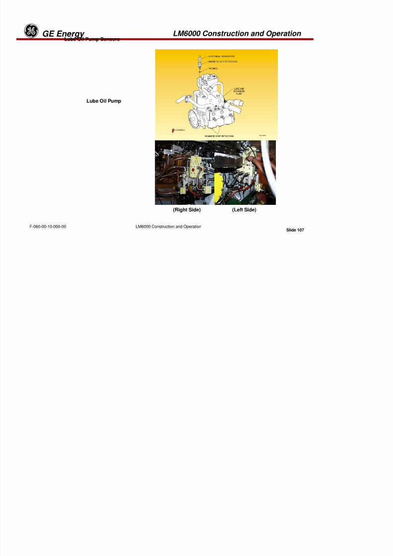
8/18/2019 71777896 - LM6000 Package Familiarization & Operations.pdf
http://slidepdf.com/reader/full/71777896-lm6000-package-familiarization-operationspdf 150/786
Slide 106LM6000 Construction and OperationF-060-00-10-000-00
Turbine Inlet Total Pressure (P4.8) Sensor
Turbine Inlet Total Pressure (P4.8) Sensor
The engine includes a LPT inlet gas total pressure(P4.8) probe located on the LPT stator case. The
interconnecting tubing between the P4.8 probe and
the thrust balance controller is mounted on the
No.4 electrical panel. The transducer tapconnection is located on the controller block.
LM6000 Construction and Operation GE EnergygLube Oil Pump Sensors

8/18/2019 71777896 - LM6000 Package Familiarization & Operations.pdf
http://slidepdf.com/reader/full/71777896-lm6000-package-familiarization-operationspdf 151/786
Slide 107LM6000 Construction and OperationF-060-00-10-000-00
Lube Oil Pump
(Right Side) (Left Side)
LM6000 Construction and Operation GE Energyg
Lube Oil Pump Sensors
Seven dual-element platinum RTDs are provided as standard equipment on theengine for measurement of the lube oil supply and scavenge oil temperature.
The RTDs sense temperatures of the bearing lube supply and scavenge from the
individual sump (accessory gearbox AGB) TGB A B C D and E sumps The
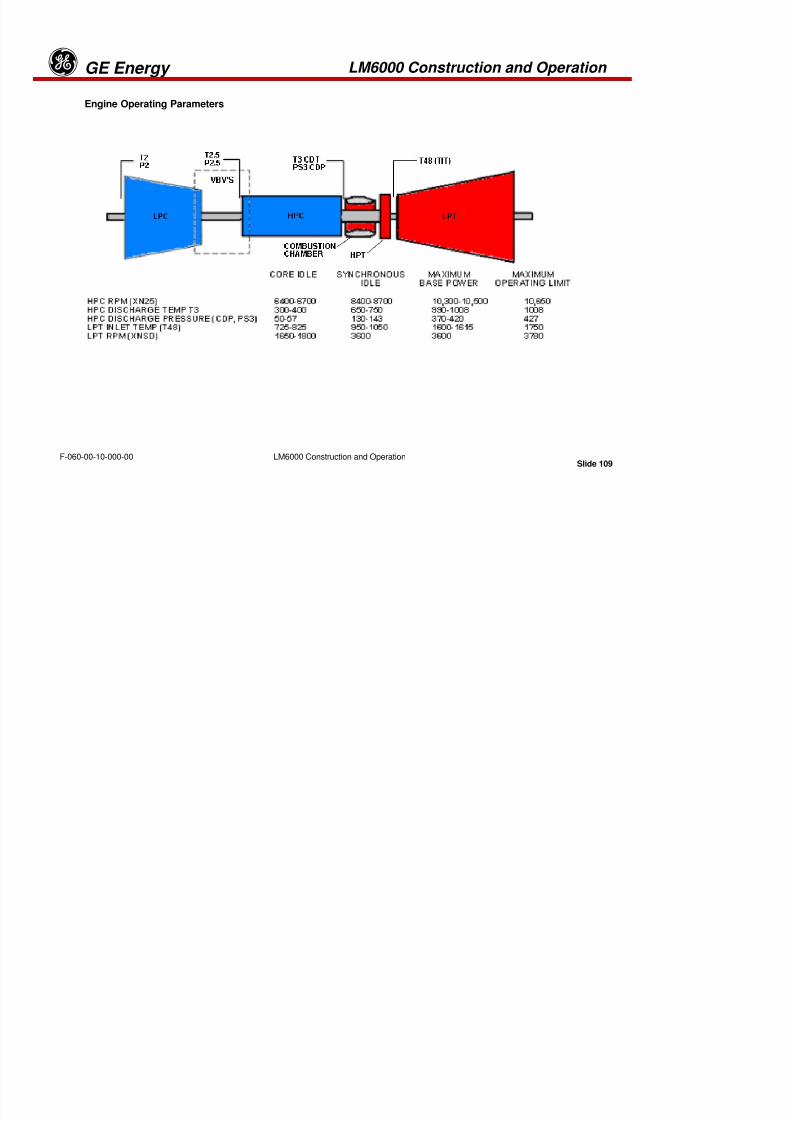
8/18/2019 71777896 - LM6000 Package Familiarization & Operations.pdf
http://slidepdf.com/reader/full/71777896-lm6000-package-familiarization-operationspdf 152/786
Slide 108LM6000 Construction and OperationF-060-00-10-000-00
individual sump (accessory gearbox AGB), TGB A, B, C, D, and E sumps. The
cables for these RTDs are routed to the No. 2 electrical panel.
The engine is equipped with electrical/magnetic remote-reading chip detectors in
the TGB, sump A, sump B and common scavenge return lines. Each standardchip detector indicates chip collection when resistance across the detectordrops. Chip detector leads are connected to the No. 2 electrical panel.
LM6000 Construction and Operation GE EnergygEngine Operating Parameters
8/18/2019 71777896 - LM6000 Package Familiarization & Operations.pdf
http://slidepdf.com/reader/full/71777896-lm6000-package-familiarization-operationspdf 153/786
Slide 109LM6000 Construction and OperationF-060-00-10-000-00
LM6000 Construction and Operation GE Energyg
Engine Operating Parameters
The major engine components, sensors and important operating parameters are illustratedon the previous page.

8/18/2019 71777896 - LM6000 Package Familiarization & Operations.pdf
http://slidepdf.com/reader/full/71777896-lm6000-package-familiarization-operationspdf 154/786
Slide 110LM6000 Construction and OperationF-060-00-10-000-00
The engine-mounted sensors noted in the chart supply data for the fuel governor and
sequencing systems.
Independent software algorithms control inlet guide vanes, VBVs, and VSVs in the off-enginecontrol system. The hydraulic actuators are an Electro-hydraulic type with built-in Linear
Voltage Differential Transformer (LVDT), which provides accurate position feedback to the
control system of the VG component.
Tab 4

8/18/2019 71777896 - LM6000 Package Familiarization & Operations.pdf
http://slidepdf.com/reader/full/71777896-lm6000-package-familiarization-operationspdf 155/786
Turbine Support Systems GE Energyg
Introduction to Turbine Support Systems,Documentation, and System Configuration

8/18/2019 71777896 - LM6000 Package Familiarization & Operations.pdf
http://slidepdf.com/reader/full/71777896-lm6000-package-familiarization-operationspdf 156/786
Slide 1Turbine Support SystemsF-060-00-20-000-00
Turbine Support Systems GE Energyg
The Gas Turbine Generator “Package” includes multiple mechanical and electrical
systems which are required for proper operation of the unit as a whole. Thesesystems include starting, lubrication, fuel delivery and air handling. For each
system described in this section, the operator will be introduced to:
8/18/2019 71777896 - LM6000 Package Familiarization & Operations.pdf
http://slidepdf.com/reader/full/71777896-lm6000-package-familiarization-operationspdf 157/786
Slide 2Turbine Support SystemsF-060-00-20-000-00
•Documentation for each system•Theory of operation
•Location of major components
•Function of components and normal operation of system
•Operator Interface Display and requirements
•Abnormal operation, alarm and shutdown actions
Turbine Support Systems GE Energyg
The mechanical and electrical drawings are the documents that define the
configuration of this unit. The mechanical and electrical drawings provided havebeen carefully detailed to include all the engineering and design data required to
fully understand and operate this turbine-generator system. The mechanical

8/18/2019 71777896 - LM6000 Package Familiarization & Operations.pdf
http://slidepdf.com/reader/full/71777896-lm6000-package-familiarization-operationspdf 158/786
Slide 3Turbine Support SystemsF-060-00-20-000-00
y p g y
drawings illustrate sub-system flows, both off-skid and on
-skid. The electrical
drawings illustrate interconnection of the devices identified on the mechanical
drawings and, therefore, should be used in conjunction with the mechanicaldrawings.
The most important “key” to reading and understanding mechanical and electrical
equipment drawings is your ability to read symbols. You must be able to identifyand read symbols to successfully interpret the technical and operational information
that equipment drawings provide. Because space is often at a minimum ondrawings, abbreviations are used to identify equipment components. Two of the
most useful drawings available to help in understanding equipment drawings arethe Flow and Equipment Symbols, Mechanical drawings and the Electrical Symbols,
Abbreviations and Reference Data Drawings.
Turbine Support Systems GE Energyg

8/18/2019 71777896 - LM6000 Package Familiarization & Operations.pdf
http://slidepdf.com/reader/full/71777896-lm6000-package-familiarization-operationspdf 159/786
Slide 4Turbine Support SystemsF-060-00-20-000-00
Flow and Equipment Symbols - Mechanical Drawings
Turbine Support Systems GE Energyg
Flow and Equipment Symbols- Mechanical drawings are used to indicate the type of
mechanical components installed in your system. They will identify the symbols andprovide the names and name abbreviations of mechanical equipment symbols,
piping symbols, hydraulic symbols, safety devices, and connection points located on

8/18/2019 71777896 - LM6000 Package Familiarization & Operations.pdf
http://slidepdf.com/reader/full/71777896-lm6000-package-familiarization-operationspdf 160/786
Slide 5Turbine Support SystemsF-060-00-20-000-00
your equipment.
Excerpts from XXX231, Flow and Equipment Symbols drawing are shown above.
Turbine Support Systems GE Energyg

8/18/2019 71777896 - LM6000 Package Familiarization & Operations.pdf
http://slidepdf.com/reader/full/71777896-lm6000-package-familiarization-operationspdf 161/786
Slide 6Turbine Support SystemsF-060-00-20-000-00
Turbine Support Systems GE Energyg
Electrical Symbols, Abbreviations and Reference Data drawings are used to indicate
the type of electrical components installed in your system. They will identify thesymbols and provide the names and name abbreviations of basic electrical symbols,
circuit breakers, contacts, relays, and switches. They will also provide you with the
symbols for transmission paths, one-line diagrams, and transformers.
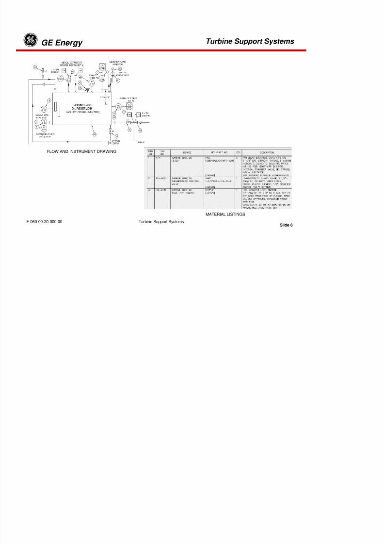
8/18/2019 71777896 - LM6000 Package Familiarization & Operations.pdf
http://slidepdf.com/reader/full/71777896-lm6000-package-familiarization-operationspdf 162/786
Slide 7Turbine Support SystemsF-060-00-20-000-00
Examples from Electrical Symbols Abbreviations and Reference Data, drawingXXX005, are shown above.
Turbine Support Systems GE Energyg

8/18/2019 71777896 - LM6000 Package Familiarization & Operations.pdf
http://slidepdf.com/reader/full/71777896-lm6000-package-familiarization-operationspdf 163/786
Slide 8Turbine Support SystemsF-060-00-20-000-00
MATERIAL LISTINGS
FLOW AND INSTRUMENT DRAWING
Turbine Support Systems GE Energyg
Flow & Instrument Diagrams
These drawings define the flow characteristics, start permissives, device set pointsand control-logic data. Flow (in gpm or scfm), filtration requirements,
pressure-limiting, and shutdown responses are identified on these drawings.
Together with the wiring and system wiring diagrams, these drawings define each
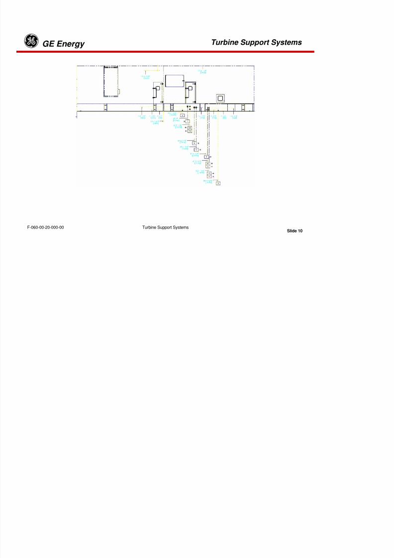
8/18/2019 71777896 - LM6000 Package Familiarization & Operations.pdf
http://slidepdf.com/reader/full/71777896-lm6000-package-familiarization-operationspdf 164/786
Slide 9Turbine Support SystemsF-060-00-20-000-00
g g y g g g
system and its related components.
Flow and Instrument Drawings also include material lists which identify each
component by tag number, device description, manufacturer, and part number.
Turbine Support Systems GE Energyg

8/18/2019 71777896 - LM6000 Package Familiarization & Operations.pdf
http://slidepdf.com/reader/full/71777896-lm6000-package-familiarization-operationspdf 165/786
Slide 10Turbine Support SystemsF-060-00-20-000-00
Turbine Support Systems GE Energyg
General Arrangement Drawings
These drawings provide isometric, plan-and-elevation, and physical configuration
data about major pieces of equipment, including skid interconnection-interfaceinformation and installation and footprint data. Data regarding the actual size and
dimensions of major equipment may also be found on these drawings.

8/18/2019 71777896 - LM6000 Package Familiarization & Operations.pdf
http://slidepdf.com/reader/full/71777896-lm6000-package-familiarization-operationspdf 166/786
Slide 11Turbine Support SystemsF-060-00-20-000-00
Turbine Support Systems GE Energyg

8/18/2019 71777896 - LM6000 Package Familiarization & Operations.pdf
http://slidepdf.com/reader/full/71777896-lm6000-package-familiarization-operationspdf 167/786
Slide 12Turbine Support SystemsF-060-00-20-000-00
Turbine Support Systems GE Energyg
This LM6000 system consists of an enclosed main (turbine) skid, a generator and one or
more auxiliary skids. The main skid contains a General Electric (GE) turbine engine(Model LM6000) connected to an air-cooled generator through an engine-generatorcoupling.

8/18/2019 71777896 - LM6000 Package Familiarization & Operations.pdf
http://slidepdf.com/reader/full/71777896-lm6000-package-familiarization-operationspdf 168/786
Slide 13Turbine Support SystemsF-060-00-20-000-00
The gas turbine generator package is equipped with a main unit enclosure. The unitenclosure is designed for outdoor installation with wind loads up to 100 mph (161 km/h).
The enclosure has separate compartments for the generator and the gas turbine. Each
compartment is provided with access doors and AC lighting.
The turbine and generator compartment walls are supported by a structural steelframework and will withstand external wind loading plus the internal pressure
developed by the fire extinguishing system. Enclosure walls are a sandwich
construction filled with insulation blankets of high temperature sound attenuationmaterial.
Turbine Support Systems GE Energyg

8/18/2019 71777896 - LM6000 Package Familiarization & Operations.pdf
http://slidepdf.com/reader/full/71777896-lm6000-package-familiarization-operationspdf 169/786
Slide 14Turbine Support SystemsF-060-00-20-000-00
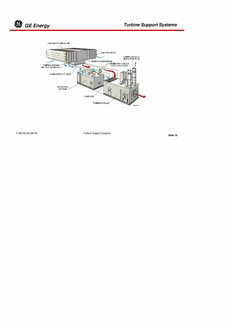
8/18/2019 71777896 - LM6000 Package Familiarization & Operations.pdf
http://slidepdf.com/reader/full/71777896-lm6000-package-familiarization-operationspdf 170/786
Turbine Support Systems GE Energyg

8/18/2019 71777896 - LM6000 Package Familiarization & Operations.pdf
http://slidepdf.com/reader/full/71777896-lm6000-package-familiarization-operationspdf 171/786
Slide 16Turbine Support SystemsF-060-00-20-000-00
Turbine Support Systems GE Energyg
Inlet Air System Module
The overhead air filter housing provides filtration for turbine combustion air andventilation air for both the turbine enclosure and generator. The inlet air system isdiscussed separately under the Ventilation and Combustion Air System. The
system also includes silencer assemblies for noise control.
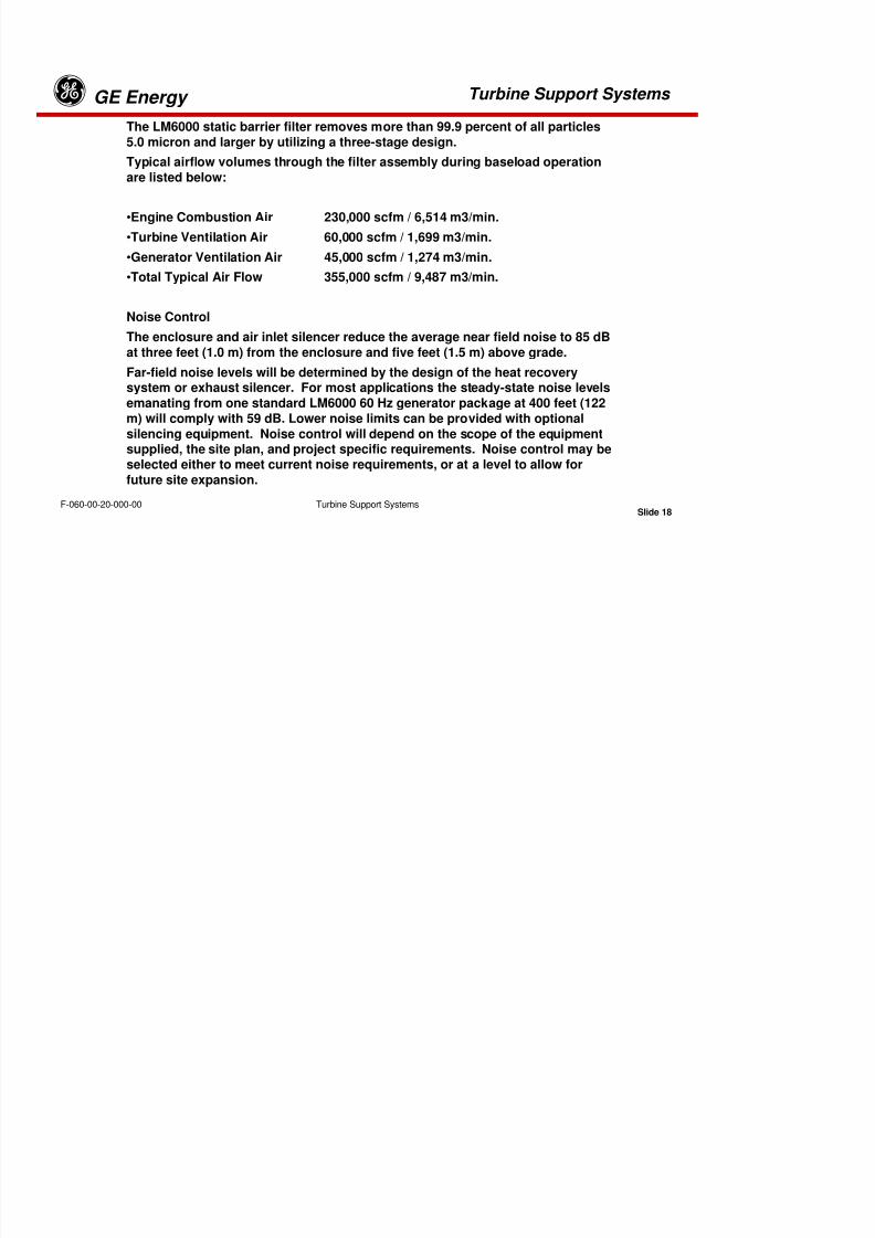
8/18/2019 71777896 - LM6000 Package Familiarization & Operations.pdf
http://slidepdf.com/reader/full/71777896-lm6000-package-familiarization-operationspdf 172/786
Slide 17Turbine Support SystemsF-060-00-20-000-00
Turbine Exhaust
The LM6000 exhausts through a flange located in the end of the turbine enclosure.This axial exhaust provides low restrictions and a direct path into optional orcustomer-supplied silencing or heat recovery equipment.
Turbine Support Systems GE EnergygThe LM6000 static barrier filter removes more than 99.9 percent of all particles
5.0 micron and larger by utilizing a three-stage design.
Typical airflow volumes through the filter assembly during baseload operation
are listed below:
•Engine Combustion Air 230,000 scfm / 6,514 m3/min.
Turbine Ventilation Air 60 000 scfm / 1 699 m3/min

8/18/2019 71777896 - LM6000 Package Familiarization & Operations.pdf
http://slidepdf.com/reader/full/71777896-lm6000-package-familiarization-operationspdf 173/786
Slide 18Turbine Support SystemsF-060-00-20-000-00
•Turbine Ventilation Air 60,000 scfm / 1,699 m3/min.•Generator Ventilation Air 45,000 scfm / 1,274 m3/min.
•Total Typical Air Flow 355,000 scfm / 9,487 m3/min.
Noise Control
The enclosure and air inlet silencer reduce the average near field noise to 85 dBat three feet (1.0 m) from the enclosure and five feet (1.5 m) above grade.
Far-field noise levels will be determined by the design of the heat recoverysystem or exhaust silencer. For most applications the steady-state noise levels
emanating from one standard LM6000 60 Hz generator package at 400 feet (122
m) will comply with 59 dB. Lower noise limits can be provided with optional
silencing equipment. Noise control will depend on the scope of the equipmentsupplied, the site plan, and project specific requirements. Noise control may beselected either to meet current noise requirements, or at a level to allow for
future site expansion.
Turbine Support Systems GE Energyg
8/18/2019 71777896 - LM6000 Package Familiarization & Operations.pdf
http://slidepdf.com/reader/full/71777896-lm6000-package-familiarization-operationspdf 174/786
Slide 19Turbine Support SystemsF-060-00-20-000-00
Turbine Support Systems GE Energyg
SKID MOUNTED AUXILIARY EQUIPMENT
Typical installations employ a primary auxiliary equipment skid which contains thefollowing equipment:
•Synthetic lube oil reservoir, duplex scavenge filter (duplex shell/tube oil-to-coolant
heat exchangers may also be mounted on this skid)
•Electro-hydraulic start system

8/18/2019 71777896 - LM6000 Package Familiarization & Operations.pdf
http://slidepdf.com/reader/full/71777896-lm6000-package-familiarization-operationspdf 175/786
Slide 20Turbine Support SystemsF-060-00-20-000-00
•Electro-hydraulic start system•On-line/off-line water wash system (including instrument air filter)
•Sprint System (Optional)
•Gas fuel filters
Separate skids my be provided for:•Liquid Fuel System
•Fire System (CO2 cylinders)
Note that auxiliary skids may be open or fully enclosed, depending on
environmental and contractual requirements.
Turbine Support Systems GE Energyg
CONTROL ROOM MOUNTED EQUIPMENT
The packaging of the LM6000 GTG set includes a turbine-generator control panel (TCP),digital generator protection relay system, 480V motor control center (MCC), and 24 and
125-VDC battery systems, including the battery racks and chargers. The control room
may customer-supplied or GE supplied skid-mounted structure.

8/18/2019 71777896 - LM6000 Package Familiarization & Operations.pdf
http://slidepdf.com/reader/full/71777896-lm6000-package-familiarization-operationspdf 176/786
Slide 21Turbine Support SystemsF-060-00-20-000-00
Tab 5

8/18/2019 71777896 - LM6000 Package Familiarization & Operations.pdf
http://slidepdf.com/reader/full/71777896-lm6000-package-familiarization-operationspdf 177/786
Turbine Lube Oil System(Woodward Control) GE Energyg

8/18/2019 71777896 - LM6000 Package Familiarization & Operations.pdf
http://slidepdf.com/reader/full/71777896-lm6000-package-familiarization-operationspdf 178/786
Slide 1Turbine Lube Oil System (Woodward Control)F-060-00-20-100-00
Turbine Lube Oil System(Woodward Control) GE Energyg
When handling oil used in gas turbines, do not allow oil to remain on skin anylonger than necessary. It contains a toxic additive that is readily absorbedthrough the skin. Personal protective equipment will be worn when handling
turbine oil.
8/18/2019 71777896 - LM6000 Package Familiarization & Operations.pdf
http://slidepdf.com/reader/full/71777896-lm6000-package-familiarization-operationspdf 179/786
Slide 2Turbine Lube Oil System (Woodward Control)F-060-00-20-100-00
NOTE: Oil consumption is not expected to exceed 0.4 gal/hr (1.5 l/hr) additional oil may be lost overboard
through the engine sump vents, depending upon efficiency of the air/oil separator(s).
Turbine Lube Oil System(Woodward Control) GE Energyg
System Overview
The Turbine Lube Oil System is shown in detail on F&ID XXX244. Please refer to the latest revision ofthis drawing for correct, site-specific configuration and settings.
The LM6000 gas turbine uses synthetic lube oil (MIL-23699, Mobil Jet Oil II, Exxon Turbo Oil 2380,
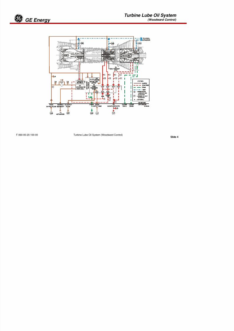
8/18/2019 71777896 - LM6000 Package Familiarization & Operations.pdf
http://slidepdf.com/reader/full/71777896-lm6000-package-familiarization-operationspdf 180/786
Slide 3Turbine Lube Oil System (Woodward Control)F-060-00-20-100-00
Castrol 5000) to:
Ø Lubricate and cool turbine bearing and gearboxes
Ø Provide oil to the variable geometry control system, fuel valves, water injection valves.
Ø Lubricate the over-running clutch for the hydraulic starter motor
The LM6000 lube oil system has two distinct sub-systems; a pressurized supply system and a separatescavenge system. Each subsystem has its own filtration.
A multi-element lube oil pump, containing both a supply (one (1)) element and scavenges elements (six
(6)) elements, circulates oil through the system. A reservoir, lube oil coolers, piping, valves, andinstrumentation complete the system.
Turbine Lube Oil System(Woodward Control) GE Energyg

8/18/2019 71777896 - LM6000 Package Familiarization & Operations.pdf
http://slidepdf.com/reader/full/71777896-lm6000-package-familiarization-operationspdf 181/786
Slide 4Turbine Lube Oil System (Woodward Control)F-060-00-20-100-00
Turbine Lube Oil System(Woodward Control) GE Energyg
TURBINE SUPPLY LUBE OIL SYSTEM
The turbine lube oil pump is mounted on the right rear side of the accessory gearbox. The supply elementtakes suction from the 150-gallon (568 liters) stainless steel turbine lube oil reservoir mounted on theauxiliary skid. Discharge pressure from the supply element is piped to the duplex supply lube oil filters,rated at six (6) microns. Two-way selector valves allow either filter to be on-line while the other is beingserviced. From the supply lube oil filters the lube oil is piped to the turbine supply header to lubricatebearings, gearboxes and the hydraulic starter clutch.
TURBINE SCAVENGE OIL SYSTEM
After the oil is supplied to the gearboxes or bearing sumps, the oil is recovered from the gearboxes and

8/18/2019 71777896 - LM6000 Package Familiarization & Operations.pdf
http://slidepdf.com/reader/full/71777896-lm6000-package-familiarization-operationspdf 182/786
Slide 5Turbine Lube Oil System (Woodward Control)F-060-00-20-100-00
sumps by one of six scavenge elements of the oil pump. Scavenged oil from “A/TGB and B” sumpspasses over magnetic chip detectors. The collective oil discharged from all the scavenge elements alsopasses over a common magnetic chip detector.
The Chip The oil then flows past a pressure relief valve which lifts when excess oil pressure is sensed,returning excess oil directly to the reservoir. The primary oil flow is then routed to the scavenge filters,where it is filtered to 6 microns. Then the oil flows to the turbine lube oil coolers, where the hot oil iscooled before being returned to the reservoir. A temperature control valve on the cooler dischargebypasses oil around the oil coolers when the oil temperature is below the setpoint. As the oil temperatureincreases, the temperature control valve starts mixing the warmer oil with cooler oil from the coolers tomaintain a preset temperature. After passing through the temperature control valve, the oil is thenreturned to the reservoir
Each engine bearing sump is provided with a sump vent line which allows sump pressurization air andentrained oil to be routed to an air/oil separator. The air/oil separator is mounted on the enclosure roof.By use of a dual-staged filter media and a fin/fan cooler, the separator removes entrained oil from the ventair. Oil is then returned to the reservoir and the vent pressurization air is released to atmosphere.
Turbine Lube Oil System(Woodward Control) GE Energyg
Turbine Lube Oil Reservoir
The lube oil reservoir is stainless steel and is located
on the auxiliary skid and has a 150 gallon (568 L)capacity. It has local indication of temperature, level,flow from the air / oil separator, and a reservoir heater(to keep lube oil temperature inside to at least 90°F(32° C)). It also has a level switch and temperatureswitch.

8/18/2019 71777896 - LM6000 Package Familiarization & Operations.pdf
http://slidepdf.com/reader/full/71777896-lm6000-package-familiarization-operationspdf 183/786
Slide 6Turbine Lube Oil System (Woodward Control)F-060-00-20-100-00
Lube Oil Supply and Scavenge Pump
The lube oil supply and scavenge pump assembly islocated on the right rear side of the accessory gearbox.It has one supply element and six scavenge elements.The supply element provides 10-18 gpm (.63 –1.13L/sec) flow, at 32-110 psig (220.6-758.4 kPag). Thepump is a positive displacement type pump. Thescavenge elements will discharge a combined total of
10-18 gpm (.63 –1.13 L/sec) at 20-80 psig (137.8-551.5kPag).
Turbine Lube Oil System(Woodward Control) GE Energyg
Scavenge Oil Filters
The duplex scavenge lube oil filters are
located on the auxiliary skid. The filterelements are rated at six (6) microns, andeach element is designed for 100% flowand pressure. The filters have a localpressure differential pressure gauge, analarm pressure differential switch set at 20psid (138kPad), and a shutdown differential
pressure switch set at 25 psid (172 kPad).

8/18/2019 71777896 - LM6000 Package Familiarization & Operations.pdf
http://slidepdf.com/reader/full/71777896-lm6000-package-familiarization-operationspdf 184/786
Slide 7Turbine Lube Oil System (Woodward Control)F-060-00-20-100-00
Supply Lube Oil FiltersThe duplex supply lube oil filters are located on theauxiliary skid. The filter elements are rated at 6micron and each element can handle 100% flowand pressure. The filters have a local pressuredifferential pressure gauge, an alarm pressuredifferential switch set at 20 psid (138kPad), and a
shutdown differential pressure switch set at 25 psid(172 kPad). NOTE: Human hair is about 100Microns in Diameter
Turbine Lube Oil System(Woodward Control) GE Energyg

8/18/2019 71777896 - LM6000 Package Familiarization & Operations.pdf
http://slidepdf.com/reader/full/71777896-lm6000-package-familiarization-operationspdf 185/786
Slide 8Turbine Lube Oil System (Woodward Control)F-060-00-20-100-00
TYPICAL LM6000 BEARINGS
“R” DESIGNATES ROLLER BEARINGS. “B” DESIGNATES BALL BEARINGS.
Turbine Lube Oil System(Woodward Control) GE Energyg
Bearings And Gearboxes
Bearings are classified into two broad categories; friction, also commonly known as plain or Babbitt type,and anti-friction, which contain rollers or balls that makes a rolling contact with the shaft. The gas turbineutilizes anti-friction type bearings, whereas the generator has friction type bearings.
Bearings have the following functions. They…
•support the load on the shaft. The load may be a gear or the shaft itself.
•reduce friction created by turning. This is accomplished both by design and by lubrication and is one of
the most important functions of bearings.
d f i ti t d b th t A i ll d i d b i i i d f thi
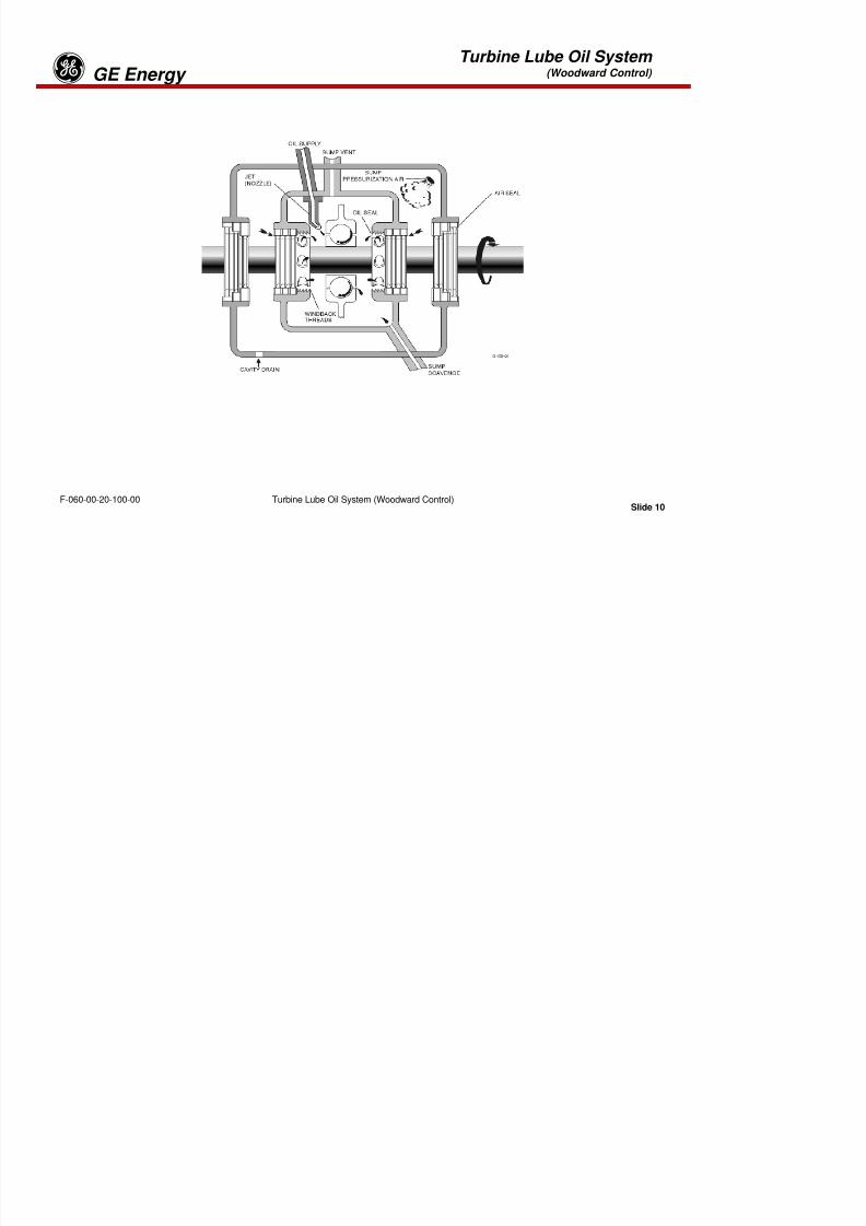
8/18/2019 71777896 - LM6000 Package Familiarization & Operations.pdf
http://slidepdf.com/reader/full/71777896-lm6000-package-familiarization-operationspdf 186/786
Slide 9Turbine Lube Oil System (Woodward Control)F-060-00-20-100-00
•reduce friction created by thrust. A specially designed bearing is required for this purpose.
•hold a shaft in rigid alignment. A high speed-rotating shaft has a tendency to “whip” unless adequatelysupported by bearings.
A pressure header provides lube oil to each of the bearings to lubricate and cool them. The roller bearingssupport the radial loads of the shafts, while the ball bearings absorb the shaft’s axial and radial loads. The
pressure header also provides oil to lubricate and cool the inlet gearbox, transfer gearbox, and theaccessory gearbox. As the oil drains through the bearing and gearboxes, it collects in sumps. Each sumpis drained by a scavenge pump that suctions the oil from the bottom of the sumps.
Turbine Lube Oil System(Woodward Control) GE Energyg
8/18/2019 71777896 - LM6000 Package Familiarization & Operations.pdf
http://slidepdf.com/reader/full/71777896-lm6000-package-familiarization-operationspdf 187/786
Slide 10Turbine Lube Oil System (Woodward Control)F-060-00-20-100-00
Turbine Lube Oil System(Woodward Control) GE Energyg
Turbine Engine Dry Sump
All sumps are pressurized by low-pressure compressor (LPC) discharge static air pressure (P25). Theairflow is of sufficient volume and pressure to maintain a positive airflow inward across the inner seals tothe inner sump cavity. This positive airflow carries with it any oil on the seals, thus retaining the oil withinthe inner cavity. Sump pressurization air enters the outer sump cavity through a pressurizing port. Thisair then passes across the oil seals into the inner sump cavity, where it is vented to the air-oil separator.Sump pressurization air also passes outward across the outer seals to the engine cavity.

8/18/2019 71777896 - LM6000 Package Familiarization & Operations.pdf
http://slidepdf.com/reader/full/71777896-lm6000-package-familiarization-operationspdf 188/786
Slide 11Turbine Lube Oil System (Woodward Control)F-060-00-20-100-00
Turbine Lube Oil System(Woodward Control) GE Energyg
8/18/2019 71777896 - LM6000 Package Familiarization & Operations.pdf
http://slidepdf.com/reader/full/71777896-lm6000-package-familiarization-operationspdf 189/786
Slide 12Turbine Lube Oil System (Woodward Control)F-060-00-20-100-00
Turbine Lube Oil System(Woodward Control) GE Energyg
The lube oil is then scavenged out of the bearing sumps and the gearboxes by one of six scavenge oilpump elements of the lube oil supply and scavenge pump. Each of the six scavenge lines are equippedwith resistance thermal devices (RTD) to measure scavenge oil temperature after leaving the bearinghousing. The RTD’s allow for operator monitoring, alarming and shutdown of the turbine if temperaturesetpoints are met.
Oil from sumps “A/TGB” and “B” is passed over two of three magnetic chip detectors. The third is locatedin the common discharge line from all scavenge oil pumps. The magnetic chip detectors detect ferrous( f i i i ) i l l i h il fl f h b i & b Thi
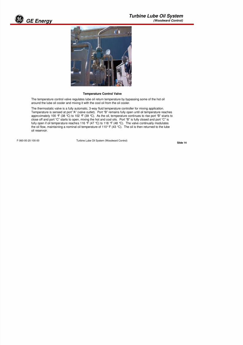
8/18/2019 71777896 - LM6000 Package Familiarization & Operations.pdf
http://slidepdf.com/reader/full/71777896-lm6000-package-familiarization-operationspdf 190/786
Slide 13Turbine Lube Oil System (Woodward Control)F-060-00-20-100-00
(of or containing iron) particulate metal in the scavenge oil flow from the bearings & gearboxes. Thiscollection of metal is usually caused by degradation of the bearings or gears in the engine. The chipdetectors normally read 300 ohms when clean. As particulate matter collects on the magnet, theresistance reading gets lower. At 100 ohms an alarm is sounded at the control console.
Turbine Lube Oil System(Woodward Control) GE Energyg

8/18/2019 71777896 - LM6000 Package Familiarization & Operations.pdf
http://slidepdf.com/reader/full/71777896-lm6000-package-familiarization-operationspdf 191/786
Slide 14Turbine Lube Oil System (Woodward Control)F-060-00-20-100-00
Temperature Control Valve
The temperature control valve regulates lube oil return temperature by bypassing some of the hot oilaround the lube oil cooler and mixing it with the cool oil from the oil cooler.
The thermostatic valve is a fully automatic, 3-way fluid temperature controller for mixing application.Temperature is sensed at port “A” (valve outlet). Port “B” remains fully open until oil temperature reachesapproximately 100 °F (38 °C) to 102 °F (39 °C). As the oil, temperature continues to rise port “B” starts toclose off and port “C” starts to open, mixing the hot and cool oils. Port “B” is fully closed and port “C” is
fully open if oil temperature reaches 116 °F (47 °C) to 118 °F (48 °C). The valve continually modulatesthe oil flow, maintaining a nominal oil temperature of 110° F (43 °C). The oil is then returned to the lubeoil reservoir.
Turbine Lube Oil System(Woodward Control) GE Energyg
LUBE OIL COOLERS
As discussed previously, the lube oil is returned to the reservoir after passing through or bypassing thelube oil cooler, as determined by the three-way thermostatically controlled valve. The lube oil coolerutilizes the principles of conduction, convection or radiation in order to transfer heat from the lube oil to amedium, typically air, water or some other fluid, depending on cooler design. Lube oil coolers employed in
the Gas Turbine Generator application are typically one of three basic designs. They are:

8/18/2019 71777896 - LM6000 Package Familiarization & Operations.pdf
http://slidepdf.com/reader/full/71777896-lm6000-package-familiarization-operationspdf 192/786
Slide 15Turbine Lube Oil System (Woodward Control)F-060-00-20-100-00
•Fin Fan Coolers (Ambient air cooled)
•Shell and Tube (water cooled)
•Plate Type (Fluid cooled)
Turbine Lube Oil System(Woodward Control) GE Energyg
8/18/2019 71777896 - LM6000 Package Familiarization & Operations.pdf
http://slidepdf.com/reader/full/71777896-lm6000-package-familiarization-operationspdf 193/786
Slide 16Turbine Lube Oil System (Woodward Control)F-060-00-20-100-00
Turbine Lube Oil System(Woodward Control) GE Energyg
Fin Fan Cooler
The “fin fan” cooler is a heat-exchanger that uses air as the cooling medium. Oil is passed through theinner tubes of the cooler, and air is forced across the outside of the tubes to decrease the temperature ofthe circulating oil. The fin fan heat exchanger is a radiator-type heat exchanger that uses electric fans toforce air through the radiator, thereby cooling the lubricating oil. After oil passes through the heatexchanger, it is routed directly to the lube oil reservoir.
During cold startups, oil may be bypassed around the fin fan heat exchanger if the thermostatic control

8/18/2019 71777896 - LM6000 Package Familiarization & Operations.pdf
http://slidepdf.com/reader/full/71777896-lm6000-package-familiarization-operationspdf 194/786
Slide 17Turbine Lube Oil System (Woodward Control)F-060-00-20-100-00
valve determines the temperature to be lower than the set point.
During normal operation, the temperature control valve regulates lube oil return temperature by bypassingsome of the hot oil around the lube oil heat exchanger and mixing it with the cool oil from the oil cooler.
The thermostatic valve is a fully automatic, three-way fluid temperature controller for mixing application.The valve continually modulates the oil flow, maintaining a nominal oil temperature.
Turbine Lube Oil System(Woodward Control) GE Energyg
8/18/2019 71777896 - LM6000 Package Familiarization & Operations.pdf
http://slidepdf.com/reader/full/71777896-lm6000-package-familiarization-operationspdf 195/786
Slide 18Turbine Lube Oil System (Woodward Control)F-060-00-20-100-00
Turbine Lube Oil System(Woodward Control) GE Energyg
Shell and Tube Type Cooler
Shell-and-tube coolers serve to cool the lubricating oil. The shell-and-tube cooler consists principally of a
bundle (also called a bank or nest) of tubes encased in a shell. The cooling liquid generally flows throughthe tubes. The liquid to be cooled enters the shell at one end, is directed to pass over the tubes by baffles,and is discharged at the opposite end of the shell. In other coolers of this type, the cooling liquid flowsthrough the shell and around the tubes; the liquid to be cooled passes through the tubes.
The tubes of the cooler are attached to the tube sheets at each end of the shell. This arrangement forms atube bundle that can be removed as a unit from the shell. The ends of the tubes are expanded to fit tightlyinto the holes in the tube sheets; they are flared at their outer edges to prevent leakage. One tube sheet
and a bonnet are bolted to the flange of the shell. This sheet is referred to as the stationary-end tubesheet. The tube sheet at the opposite end floats in the shell, a design that allows for expansion of the tubebundle. Packing rings, which prevent leakage past the floating-end tube sheet, are fitted at the floating end
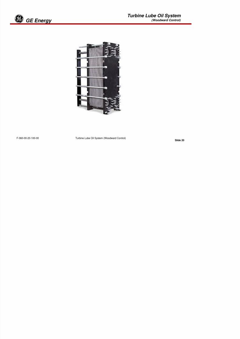
8/18/2019 71777896 - LM6000 Package Familiarization & Operations.pdf
http://slidepdf.com/reader/full/71777896-lm6000-package-familiarization-operationspdf 196/786
Slide 19Turbine Lube Oil System (Woodward Control)F-060-00-20-100-00
g g p g p g gbetween the shell flange and the bonnet. The packing joint allows for expansion and prevents the mixingof the cooling liquid with the liquid to be cooled in-side the shell by means of a leak-off, or lantern, glandthat is vented to the atmosphere. Transverse baffles are arranged around the tube bundle in such amanner that the liquid is directed from side to side as it flows around the tubes and through the shell. Thedeflection of the liquid ensures the maximum cooling effect. Several of the baffles serve as supports forthe bank of tubes. These baffles are of heavier construction than those that only deflect the liquid.
Turbine Lube Oil System(Woodward Control) GE Energyg

8/18/2019 71777896 - LM6000 Package Familiarization & Operations.pdf
http://slidepdf.com/reader/full/71777896-lm6000-package-familiarization-operationspdf 197/786
Slide 20Turbine Lube Oil System (Woodward Control)F-060-00-20-100-00
Turbine Lube Oil System(Woodward Control) GE Energyg
Plate Heat Exchangers
Plate heat exchangers use a number of gasketed metal plates that are compressed together. The platesare designed to allow transfer of heat from one circulating fluid to another.
Cooling water enters and flows through one plate, while lube oil flows through the next. Inside the heatexchanger, plates are arranged to provide alternate hot and cold sections, thereby sandwiching the hotlube oil plates between two cold water plates and allowing maximum heat transfer. As oil and water flows
through the plates, the large surface area allows heat to be transferred from the hot lube oil to the coolercirculating water.

8/18/2019 71777896 - LM6000 Package Familiarization & Operations.pdf
http://slidepdf.com/reader/full/71777896-lm6000-package-familiarization-operationspdf 198/786
Slide 21Turbine Lube Oil System (Woodward Control)F-060-00-20-100-00
Plate heat exchangers are more efficient than conventional shell and tube heat exchangers because theyprovide more surface area for better heat transfer. In addition they are smaller in size, require less water,and can operate at higher pressures than comparable shell and tube heat exchangers.
Turbine Lube Oil System(Woodward Control) GE Energyg
8/18/2019 71777896 - LM6000 Package Familiarization & Operations.pdf
http://slidepdf.com/reader/full/71777896-lm6000-package-familiarization-operationspdf 199/786
Slide 22Turbine Lube Oil System (Woodward Control)F-060-00-20-100-00
Turbine Lube Oil System(Woodward Control) GE Energyg
Air / Oil Separator
Bearing sump vent air goes to an air/oil separator located on the roof of the enclosure. The air/oilseparator is a two-stage design with a heat exchanger between the stages. The vent air flows through thefirst separator, which has a filter pad that collects most of the oil mist trapped in the vent air. The vent airthen goes through an air-to-vent air heat exchanger, followed by the second stage of oil separationpassing through a filter pad in the second separator chamber. Collected oil is returned to the turbine lubeoil reservoir and the air is discharged to atmosphere.
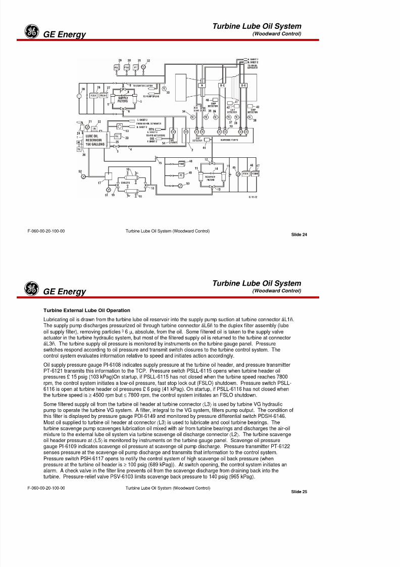
8/18/2019 71777896 - LM6000 Package Familiarization & Operations.pdf
http://slidepdf.com/reader/full/71777896-lm6000-package-familiarization-operationspdf 200/786
Slide 23Turbine Lube Oil System (Woodward Control)F-060-00-20-100-00
Turbine Lube Oil System(Woodward Control) GE Energyg

8/18/2019 71777896 - LM6000 Package Familiarization & Operations.pdf
http://slidepdf.com/reader/full/71777896-lm6000-package-familiarization-operationspdf 201/786
Slide 24Turbine Lube Oil System (Woodward Control)F-060-00-20-100-00
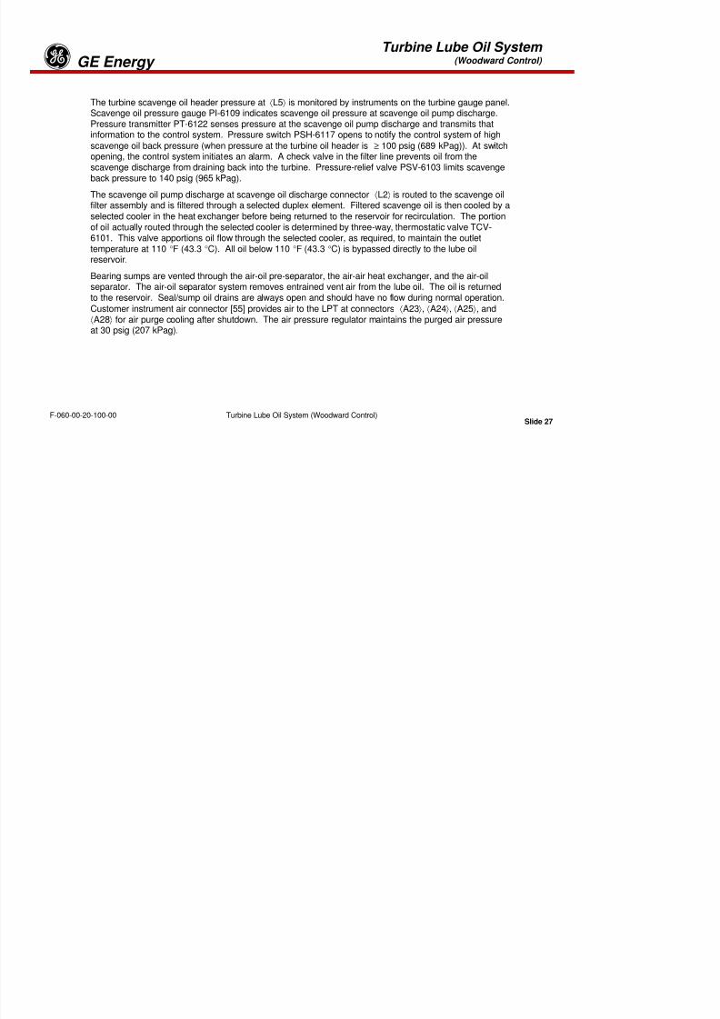
8/18/2019 71777896 - LM6000 Package Familiarization & Operations.pdf
http://slidepdf.com/reader/full/71777896-lm6000-package-familiarization-operationspdf 202/786
Turbine Lube Oil System(Woodward Control) GE Energyg

8/18/2019 71777896 - LM6000 Package Familiarization & Operations.pdf
http://slidepdf.com/reader/full/71777896-lm6000-package-familiarization-operationspdf 203/786
Slide 26Turbine Lube Oil System (Woodward Control)F-060-00-20-100-00
Turbine Lube Oil System(Woodward Control) GE Energyg
The turbine scavenge oil header pressure at ⟨L5⟩ is monitored by instruments on the turbine gauge panel.Scavenge oil pressure gauge PI-6109 indicates scavenge oil pressure at scavenge oil pump discharge.
Pressure transmitter PT-6122 senses pressure at the scavenge oil pump discharge and transmits thatinformation to the control system. Pressure switch PSH-6117 opens to notify the control system of highscavenge oil back pressure (when pressure at the turbine oil header is ≥ 100 psig (689 kPag)). At switchopening, the control system initiates an alarm. A check valve in the filter line prevents oil from thescavenge discharge from draining back into the turbine. Pressure-relief valve PSV-6103 limits scavengeback pressure to 140 psig (965 kPag).
The scavenge oil pump discharge at scavenge oil discharge connector ⟨L2⟩ is routed to the scavenge oil
filter assembly and is filtered through a selected duplex element. Filtered scavenge oil is then cooled by aselected cooler in the heat exchanger before being returned to the reservoir for recirculation. The portionof oil actually routed through the selected cooler is determined by three-way, thermostatic valve TCV-6101 This al e apportions oil flo thro gh the selected cooler as req ired to maintain the o tlet

8/18/2019 71777896 - LM6000 Package Familiarization & Operations.pdf
http://slidepdf.com/reader/full/71777896-lm6000-package-familiarization-operationspdf 204/786
Slide 27Turbine Lube Oil System (Woodward Control)F-060-00-20-100-00
6101. This valve apportions oil flow through the selected cooler, as required, to maintain the outlettemperature at 110 °F (43.3 °C). All oil below 110 °F (43.3 °C) is bypassed directly to the lube oilreservoir.
Bearing sumps are vented through the air-oil pre-separator, the air-air heat exchanger, and the air-oil
separator. The air-oil separator system removes entrained vent air from the lube oil. The oil is returnedto the reservoir. Seal/sump oil drains are always open and should have no flow during normal operation.Customer instrument air connector [55] provides air to the LPT at connectors ⟨A23⟩, ⟨A24⟩, ⟨A25⟩, and⟨A28⟩ for air purge cooling after shutdown. The air pressure regulator maintains the purged air pressureat 30 psig (207 kPag).
Turbine Lube Oil System(Woodward Control) GE Energyg

8/18/2019 71777896 - LM6000 Package Familiarization & Operations.pdf
http://slidepdf.com/reader/full/71777896-lm6000-package-familiarization-operationspdf 205/786
Slide 28Turbine Lube Oil System (Woodward Control)F-060-00-20-100-00
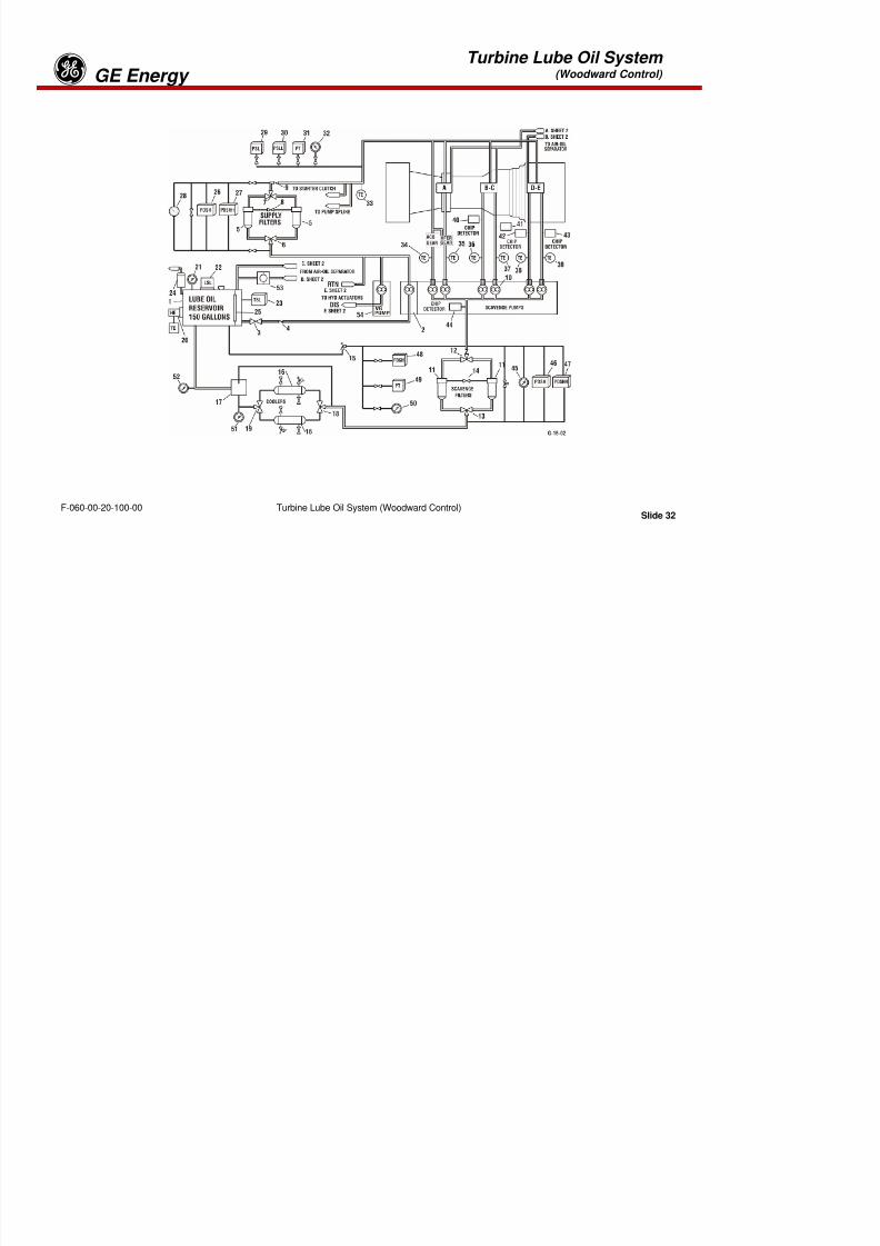
8/18/2019 71777896 - LM6000 Package Familiarization & Operations.pdf
http://slidepdf.com/reader/full/71777896-lm6000-package-familiarization-operationspdf 206/786
Turbine Lube Oil System(Woodward Control) GE Energyg

8/18/2019 71777896 - LM6000 Package Familiarization & Operations.pdf
http://slidepdf.com/reader/full/71777896-lm6000-package-familiarization-operationspdf 207/786
Slide 30Turbine Lube Oil System (Woodward Control)F-060-00-20-100-00
Turbine Lube Oil System(Woodward Control) GE Energyg
Turbine Lube Oil Duplex Filters
The lube oil supply and scavenge oil filter assemblies are located on the auxiliary skid. Except forexternal instrumentation, the two assemblies are identical. Each is a duplex, full-flow assembly, with twosteel filter shells and replaceable 6-µ-absolute filter elements. A manual shuttle valve may be used todivert oil flow through one element, allowing the other element to be serviced without interruption ofoperation. For each duplex filter, a differential pressure gauge and two differential pressure switches,located on the auxiliary skid gauge panel and JB-55, warn operating personnel of dirty filter elements.The instruments may be isolated from the system by means of instrument valves while a differentialpressure balance valve permits equalizing pressure across the instruments.
The lubricating oil system contains three instruments for monitoring operation at the supply and scavengeduplex filter assemblies: (1) differential pressure gauges PDI 6106 and PDI 6107 indicate filterdifferential pressure in the range of 0–30 psid (0-207 kPad), (2) differential pressure switches PDSH 6120

8/18/2019 71777896 - LM6000 Package Familiarization & Operations.pdf
http://slidepdf.com/reader/full/71777896-lm6000-package-familiarization-operationspdf 208/786
Slide 31Turbine Lube Oil System (Woodward Control)F-060-00-20-100-00
p g p ( ), ( ) pand PDSH 6118 signal the control system to initiate an alarm if the pressure drop across the oil filter risesto 20 psid (138 kPad), and (3) differential pressure switches PDSHH 6144 and PDSHH 6119 signal thecontrol system to initiate a cool-down lockout (CDLO) shutdown if the pressure drop across the oil filterrises to 25 psid (172 kPad).
Turbine Lube Oil Heat Exchangers
The shell and tube heat exchanger assembly is located on the auxiliary skid. The lube oil may bypass thecoolers if thermostatic control valve TCV-6101 determines the temperature to be < 110 °F (430 °C). Afterthe lube oil passes through control valve TCV-6101, temperature indicator TI-6137 measures actual lubeoil temperature. This indicator is scaled 0-250 °F (0-121 °C). The lube oil is then routed directly to thereservoir.
Turbine Lube Oil System(Woodward Control) GE Energyg

8/18/2019 71777896 - LM6000 Package Familiarization & Operations.pdf
http://slidepdf.com/reader/full/71777896-lm6000-package-familiarization-operationspdf 209/786
Slide 32Turbine Lube Oil System (Woodward Control)F-060-00-20-100-00
Turbine Lube Oil System(Woodward Control) GE Energyg
Air-Oil Separator
The turbine air-oil pre-separator, air-air heat exchanger, and the air-oil separator are located on the roof ofthe turbine enclosure and vent to the atmosphere. Turbine engine sumps A/B and C, at engine connectoráA9ñ, are connected to the separator via a 6-inch line. Sumps D and E, at engine connector áA10ñ, arealso connected to the separator via a 6-inch (15 cent.) line. The pre-separated oil is drained to the turbinelube oil tank via a 1½-inch (3.8 cent) line, the air is vented to the air-air heat exchanger where it is cooled,and then, the air is vented to the air-oil separator. The separated oil is drained to the turbine lube oil tankvia a trapped ½-inch (1.3 cent.) line, and the air is vented to the atmosphere. A sight gauge allowsoperating personnel to observe oil flow from the pre-separator to the lube oil tank. Pressure switch PDSH-
6148 indicates excessive differential pressure and initiates alarm PDAH-6148 if pressures increase to ³1.75 psid (12 kPad).

8/18/2019 71777896 - LM6000 Package Familiarization & Operations.pdf
http://slidepdf.com/reader/full/71777896-lm6000-package-familiarization-operationspdf 210/786
Slide 33Turbine Lube Oil System (Woodward Control)F-060-00-20-100-00
Turbine Lube Oil System(Woodward Control) GE Energyg

8/18/2019 71777896 - LM6000 Package Familiarization & Operations.pdf
http://slidepdf.com/reader/full/71777896-lm6000-package-familiarization-operationspdf 211/786
Slide 34Turbine Lube Oil System (Woodward Control)F-060-00-20-100-00
Turbine Lube Oil System(Woodward Control) GE Energyg
Turbine Lube Oil System HMI Display
The typical Turbine Lube Oil System HMI display screen is laid out similar to the Flow and InstrumentDiagram. Reservoir temperature and level switches and the state of the heater are displayed. Lube oilsupply and scavenge pressures are displayed as well as the state of high and low pressure switches.Differential pressure across supply, scavenge, and VG oil filters is displayed. Scavenge oil temperatures,as measured by the dual element RTDs, are displayed.
The state of the air/oil separator cooler fan motor is displayed as well as differential pressure betweenseparator stages.

8/18/2019 71777896 - LM6000 Package Familiarization & Operations.pdf
http://slidepdf.com/reader/full/71777896-lm6000-package-familiarization-operationspdf 212/786
Slide 35Turbine Lube Oil System (Woodward Control)F-060-00-20-100-00
Turbine Lube Oil System(Woodward Control) GE Energyg
Gas Turbine Lube Oil System Review
1. What are the two aspects of the turbine lube oil system that requires special attention regardingpersonal safety on the part of the operator?
A.__________________________
B.__________________________
2. The variable geometry control pump supplies turbine lube oil to the engine fuel valve actuator(s).
A. True B. False
3. Turbine lube oil for the most part is maintained at a constant pressure after the engine has attainedsynchronous rpm.

8/18/2019 71777896 - LM6000 Package Familiarization & Operations.pdf
http://slidepdf.com/reader/full/71777896-lm6000-package-familiarization-operationspdf 213/786
Slide 36Turbine Lube Oil System (Woodward Control)F-060-00-20-100-00
A. True B. False
4. Can the duplex lube oil supply filters be transferred in and out of service during unit operation?
A. True B. False
5. The engine's lube oil system coolers use ____ as the cooling media.
A. The primary air system C. Ambient air
B. The secondary air system D. Water
6. The temperature of the oil in the turbine lube oil reservoir tank will be maintained at ____.
A. 70 °F C. 90 °F
B. 80 °F D. 100 °F
Turbine Lube Oil System(Woodward Control) GE Energyg
7. Turbine lube oil temperature is controlled by ____.
A. Variable speed cooler fans
B. Regulating flow through or bypassing the lube oil coolerC. Throttling the rate of flow through the engine
D. None of the above
8. Engine shutdown occurs if lube oil pressure is not above specific minimum values as speedincreases.
A. True B. False
9. Bearing cavity seals within the engine are .
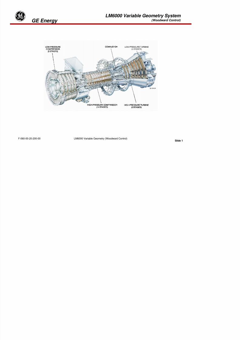
8/18/2019 71777896 - LM6000 Package Familiarization & Operations.pdf
http://slidepdf.com/reader/full/71777896-lm6000-package-familiarization-operationspdf 214/786
Slide 37Turbine Lube Oil System (Woodward Control)F-060-00-20-100-00
9. Bearing cavity seals within the engine are ____.
A. Spring-loaded carbon
B. Single labyrinth
C. Double labyrinth with air pressure between
10. All dual-redundant lube oil filters that can be replaced without engine shutdown can be servicedwithout entering the turbine enclosure.
A. True B. False
11. What type of oil can you use on the LM6000?
Turbine Lube Oil System(Woodward Control) GE Energyg
12. Can you mix different types of oil in the turbine sump?
13. Where is the oil pump mounted?
14. Why isn’t there a “backup” lube oil system to protect the turbine bearings if the primary pumpshould fail?
15. What does the “Scavenge Oil System” do?
16. Depending on customers needs, a lube oil system might have Plate & Frame, Shell & Tube or Fin-Fan Coolers Why would a customer choose one of these types over the other type?

8/18/2019 71777896 - LM6000 Package Familiarization & Operations.pdf
http://slidepdf.com/reader/full/71777896-lm6000-package-familiarization-operationspdf 215/786
Slide 38Turbine Lube Oil System (Woodward Control)F-060-00-20-100-00
Fan Coolers. Why would a customer choose one of these types over the other type?
17. What is the purpose of having Lube oil analyzed?
18. How can you check for free water in an oil sample?
Tab 6

8/18/2019 71777896 - LM6000 Package Familiarization & Operations.pdf
http://slidepdf.com/reader/full/71777896-lm6000-package-familiarization-operationspdf 216/786
LM6000 Variable Geometry System (Woodward Control) GE Energy

8/18/2019 71777896 - LM6000 Package Familiarization & Operations.pdf
http://slidepdf.com/reader/full/71777896-lm6000-package-familiarization-operationspdf 217/786
Slide 1LM6000 Variable Geometry (Woodward Control)F-060-00-20-200-00
LM6000 Variable Geometry System (Woodward Control) GE Energy

8/18/2019 71777896 - LM6000 Package Familiarization & Operations.pdf
http://slidepdf.com/reader/full/71777896-lm6000-package-familiarization-operationspdf 218/786
Slide 2LM6000 Variable Geometry (Woodward Control)F-060-00-20-200-00
LM6000 Variable Geometry System (Woodward Control) GE Energy
Variable Geometry System Overview
The Turbine Lube Oil System supplies oil for the Variable Geometry (VG) System
The VG system consists of:
•VG hydraulic pump
•VG hydraulic pump oil filter
•Hydraulic control unit (HCU), which houses torque motor-positioned hydraulic servos for portingfluid at regulated pressure
•Two Variable Inlet Guide Vane (VIGV) actuators (optional)
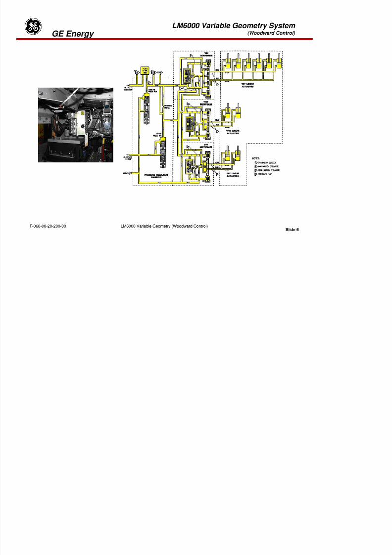
8/18/2019 71777896 - LM6000 Package Familiarization & Operations.pdf
http://slidepdf.com/reader/full/71777896-lm6000-package-familiarization-operationspdf 219/786
Slide 3LM6000 Variable Geometry (Woodward Control)F-060-00-20-200-00
•Six Variable Bypass Valve (VBV) actuators
•Two Variable Stator Vane (VSV) actuators
LM6000 Variable Geometry System (Woodward Control) GE Energy

8/18/2019 71777896 - LM6000 Package Familiarization & Operations.pdf
http://slidepdf.com/reader/full/71777896-lm6000-package-familiarization-operationspdf 220/786
Slide 4LM6000 Variable Geometry (Woodward Control)F-060-00-20-200-00
LM6000 Variable Geometry System (Woodward Control) GE Energy
VG System Operation
The VG hydraulic pump is a fixed-displacement pump which supplies pressurized lube oil to the HCU fordelivery to the actuators.
Positioning of the VIGVs, VSVs and VBVs is scheduled by the Millennium or Netcon Control System(provided with the unit). Electrical inputs to separate servo valves in the HCU, which is mounted on theVG hydraulic pump, position the servo valves in the correct position. Position feedback to the controlsystem is provided by Linear Variable Differential Transformers (LVDTs) integral to the individual systemactuators.

8/18/2019 71777896 - LM6000 Package Familiarization & Operations.pdf
http://slidepdf.com/reader/full/71777896-lm6000-package-familiarization-operationspdf 221/786
Slide 5LM6000 Variable Geometry (Woodward Control)F-060-00-20-200-00
LM6000 Variable Geometry System (Woodward Control) GE Energy

8/18/2019 71777896 - LM6000 Package Familiarization & Operations.pdf
http://slidepdf.com/reader/full/71777896-lm6000-package-familiarization-operationspdf 222/786
Slide 6LM6000 Variable Geometry (Woodward Control)F-060-00-20-200-00
LM6000 Variable Geometry System (Woodward Control) GE Energy
Hydraulic Control Unit
The HCU controls the hydraulic pressure for the servo system. The HCU receives oil from the VGC pump.This oil is filtered in a single filter (for safety reasons only, since the oil has already passed the lube oilfilter). From the filter the oil flows to two control valves, one adjusted to 83 bar for the VBV system via theinternal connections in the HCU and VGC pump.
The HCU contains three servo valves, for the IGV, VBV and VSV control system. The other servosystems operate with servo valves that are incorporated in the control valve assemblies. The servo valves
in the HCU operate on DC signal with the following characteristics:•Null bias current 20+/- 2 mA
•Normal current in coil -80 to 120 mA (100 mA nominally)
•Maximal current -350 to 350 mA

8/18/2019 71777896 - LM6000 Package Familiarization & Operations.pdf
http://slidepdf.com/reader/full/71777896-lm6000-package-familiarization-operationspdf 223/786
Slide 7LM6000 Variable Geometry (Woodward Control)F-060-00-20-200-00
•Resistance of coil 27 to 63 Ohms
LM6000 Variable Geometry System (Woodward Control) GE Energy

8/18/2019 71777896 - LM6000 Package Familiarization & Operations.pdf
http://slidepdf.com/reader/full/71777896-lm6000-package-familiarization-operationspdf 224/786
Slide 8LM6000 Variable Geometry (Woodward Control)F-060-00-20-200-00
LM6000 Variable Geometry System (Woodward Control) GE Energy
Variable Inlet Guide Vanes
Two hydraulic actuators (3 and 9 o’clock) operate the variable VIGVs for the LPC. Both actuators havean internal LVDT (position transducer) for the feedback signal to the control system. At low compressorspeed the VIGVs are kept in the minimum position in order to limit the airflow through both the LPC andthe HPC.
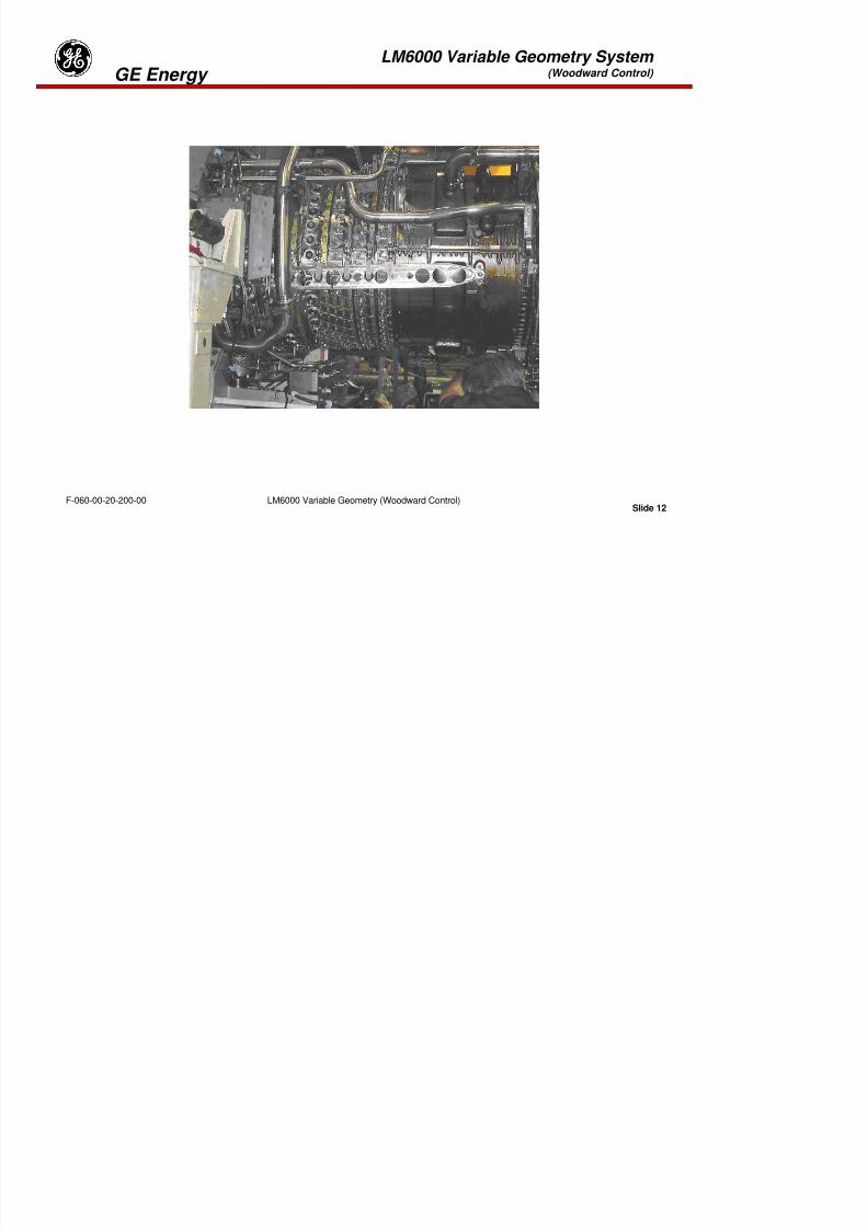
8/18/2019 71777896 - LM6000 Package Familiarization & Operations.pdf
http://slidepdf.com/reader/full/71777896-lm6000-package-familiarization-operationspdf 225/786
Slide 9LM6000 Variable Geometry (Woodward Control)F-060-00-20-200-00
LM6000 Variable Geometry System (Woodward Control) GE Energy

8/18/2019 71777896 - LM6000 Package Familiarization & Operations.pdf
http://slidepdf.com/reader/full/71777896-lm6000-package-familiarization-operationspdf 226/786
Slide 10LM6000 Variable Geometry (Woodward Control)F-060-00-20-200-00
LM6000 Variable Geometry System (Woodward Control) GE Energy
Variable Bypass Valve (VBV) System
The VBV system is located on the compressor front frame assembly. It is used to vent LPC discharge airoverboard through the LPC bleed air collector, in order to maintain LPC stall margin during starting, partialpower operation, and large power transients. The VBV system consists of 12 variable-position bypassvalves, six VBV actuators (two with LVDTs), six actuator bellcranks, 12 VBV bellcranks, and an actuationring.
The actuators are located at the 1:00, 3:00, 5:00, 7:00, 9:00, and 11:00 o’clock positions on thecompressor front frame. The six actuators are positioned with one VBV on each side of each actuator.The actuators, actuation ring and VBVs are mechanically linked by bellcranks and pushrods. Theactuators position the actuation ring, which opens and closes the VBVs. The 5:00 and 11:00 o’clockactuators are equipped with integral LVDTs for position indication. The Millennium Control System isdesigned to control VBV position by means of closed-loop scheduling of VBV actuator position, based onLPC inlet temperature (T2) and high pressure (HP) rotor speed corrected to inlet conditions (XN25R2).
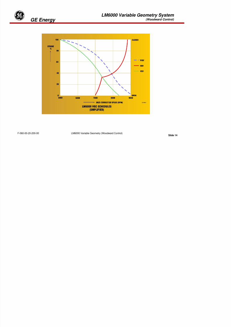
8/18/2019 71777896 - LM6000 Package Familiarization & Operations.pdf
http://slidepdf.com/reader/full/71777896-lm6000-package-familiarization-operationspdf 227/786
Slide 11LM6000 Variable Geometry (Woodward Control)F-060-00-20-200-00
LM6000 Variable Geometry System (Woodward Control) GE Energy

8/18/2019 71777896 - LM6000 Package Familiarization & Operations.pdf
http://slidepdf.com/reader/full/71777896-lm6000-package-familiarization-operationspdf 228/786
Slide 12LM6000 Variable Geometry (Woodward Control)F-060-00-20-200-00
LM6000 Variable Geometry System (Woodward Control) GE Energy
Variable Stator Vane (VSV) System
The VSV system consists of two VSV actuators and levers, actuation rings, and linkages for each VSV
stage.The VSV system has two hydraulic actuators, located at the 3:00 and 9:00 o’clock positions. Eachactuator is equipped with an integral LVDT for position feedback. The Millennium Control Systemcontrols VSV position by means of closed-loop scheduling of VSV actuator position, based on correctedhigh-pressure (HP) rotor speed (XN25R).
The VSV system has a number of natural wear points that must be inspected on a regular basis. Bykeeping the system in good physical condition, accurate positioning of the vanes is possible. Misadjusted
or worn vanes, or worn vane bushings, can cause a significant increase in the cyclic loading imparted onthe rotating blades in the compressor.
Wear can be drastically accelerated by allowing the external surfaces to become dirty and/or oily overtime. This mixture combines to form a paste very similar to lapping compound. Consequently, each timethe system cycles, the wear surfaces are “lapped” and clearances increase at an ever accelerating rate.

8/18/2019 71777896 - LM6000 Package Familiarization & Operations.pdf
http://slidepdf.com/reader/full/71777896-lm6000-package-familiarization-operationspdf 229/786
Slide 13LM6000 Variable Geometry (Woodward Control)F-060-00-20-200-00
External surfaces can be cleaned following work package 4011.
LM6000 Variable Geometry System (Woodward Control) GE Energy

8/18/2019 71777896 - LM6000 Package Familiarization & Operations.pdf
http://slidepdf.com/reader/full/71777896-lm6000-package-familiarization-operationspdf 230/786
Slide 14LM6000 Variable Geometry (Woodward Control)F-060-00-20-200-00
LM6000 Variable Geometry System (Woodward Control) GE Energy
VGC Schedules
The simplified “LM6000 VGC schedules” show that during low speeds of XN25:
IGVs are closed (minimum position)
VBVs are open
VSVs of the HPC are closed (minimum position)
As the HPC speed goes up, the VGC components gradually obtain their full speed positions. Besides the
HPC speed, the air inlet temperature has an influence on the required VGV positions. Therfore, the HPCspeed signal XN25 will be corrected with a factor derived from the HP compressor inlet temperature T25.
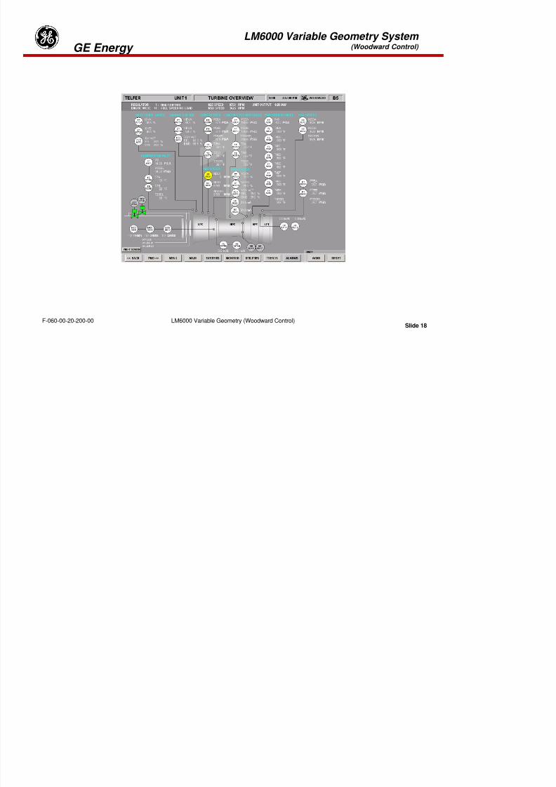
8/18/2019 71777896 - LM6000 Package Familiarization & Operations.pdf
http://slidepdf.com/reader/full/71777896-lm6000-package-familiarization-operationspdf 231/786
Slide 15LM6000 Variable Geometry (Woodward Control)F-060-00-20-200-00
LM6000 Variable Geometry System (Woodward Control) GE Energy

8/18/2019 71777896 - LM6000 Package Familiarization & Operations.pdf
http://slidepdf.com/reader/full/71777896-lm6000-package-familiarization-operationspdf 232/786
Slide 16LM6000 Variable Geometry (Woodward Control)F-060-00-20-200-00
LM6000 Variable Geometry System (Woodward Control) GE Energy
Variable Geometry Hydraulic Pump.The variable geometry hydraulic pump is a positive displacement pump that supplies the hydraulic controlunit (HCU) with the correct oil flow and pressure to move the variable bleed valves (VBVs) and thevariable stator vanes (VSVs) to the required position.
Variable Geometry Hydraulic Pump Oil Filter
The VG pump filter is mounted near the discharge of VG pump, on the engine accessory gearbox. The
filter is rated at 40u. The filter also has a pressure differential switch set at 20 psid (138kPad), whichsends a signal to the turbine control system for alarm indication.
Hydraulic Control Unit (HCU)
The hydraulic control unit receives position signals from the turbine control system. The HCU housestorque motor-positioned hydraulic servos to direct hydraulic fluid at regulated pressure to the VBV
t t d / th VSV t t t th b iti

8/18/2019 71777896 - LM6000 Package Familiarization & Operations.pdf
http://slidepdf.com/reader/full/71777896-lm6000-package-familiarization-operationspdf 233/786
Slide 17LM6000 Variable Geometry (Woodward Control)F-060-00-20-200-00
actuators and / or the VSV actuators, or to the bypass position.
LM6000 Variable Geometry System (Woodward Control) GE Energy
8/18/2019 71777896 - LM6000 Package Familiarization & Operations.pdf
http://slidepdf.com/reader/full/71777896-lm6000-package-familiarization-operationspdf 234/786
Slide 18LM6000 Variable Geometry (Woodward Control)F-060-00-20-200-00
LM6000 Variable Geometry System (Woodward Control) GE Energy
Variable Geometry System demand and position feedback data is displayed on the Turbine Overview
screen in the HMI. For each system, both LVDT positions are displayed in addition to the positiondemand and the selected position feedback signal used for control.

8/18/2019 71777896 - LM6000 Package Familiarization & Operations.pdf
http://slidepdf.com/reader/full/71777896-lm6000-package-familiarization-operationspdf 235/786
Slide 19LM6000 Variable Geometry (Woodward Control)F-060-00-20-200-00
LM6000 Variable Geometry System (Woodward Control) GE Energy
Variable Geometry System Review
1. The variable geometry (VG) system consists of:
•_________________________
•_________________________
•_________________________
•_________________________
•_________________________
2. The VG hydraulic pump is a ________________ type pump.
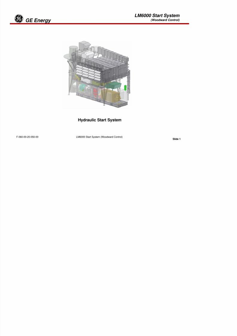
8/18/2019 71777896 - LM6000 Package Familiarization & Operations.pdf
http://slidepdf.com/reader/full/71777896-lm6000-package-familiarization-operationspdf 236/786
Slide 20LM6000 Variable Geometry (Woodward Control)F-060-00-20-200-00
3. Position feedback to the control system is provided by___________________.
4. Name the three servo valves in the HCU.
1._____________________________
2._____________________________
3._____________________________
LM6000 Variable Geometry System (Woodward Control) GE Energy
5. The VBV system consists of ____ variable-position bypass valves, ____ VBV actuators (two withLVDTs), _____ actuator bellcranks, _____ VBV bellcranks, and an actuation ring.
6. The ______ and _______ o’clock actuators are equipped with integral LVDTs for positionindication on the VBV.
7. The VG filter is rated at ________ micron.
8. What type of oil is used on the Variable Geometry?
9. Hydraulic oil for the TBV is being received from?

8/18/2019 71777896 - LM6000 Package Familiarization & Operations.pdf
http://slidepdf.com/reader/full/71777896-lm6000-package-familiarization-operationspdf 237/786
Slide 21LM6000 Variable Geometry (Woodward Control)F-060-00-20-200-00
10. At what pressure will the oil filter bypass?
Tab 7
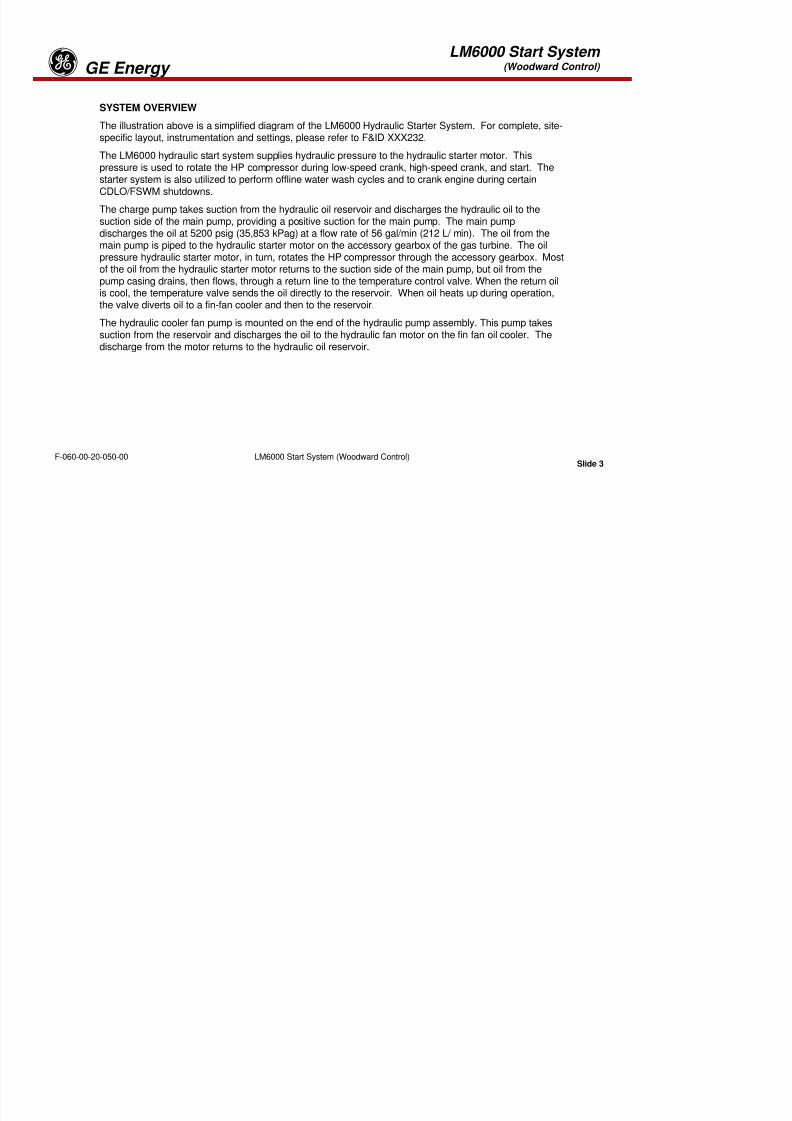
8/18/2019 71777896 - LM6000 Package Familiarization & Operations.pdf
http://slidepdf.com/reader/full/71777896-lm6000-package-familiarization-operationspdf 238/786
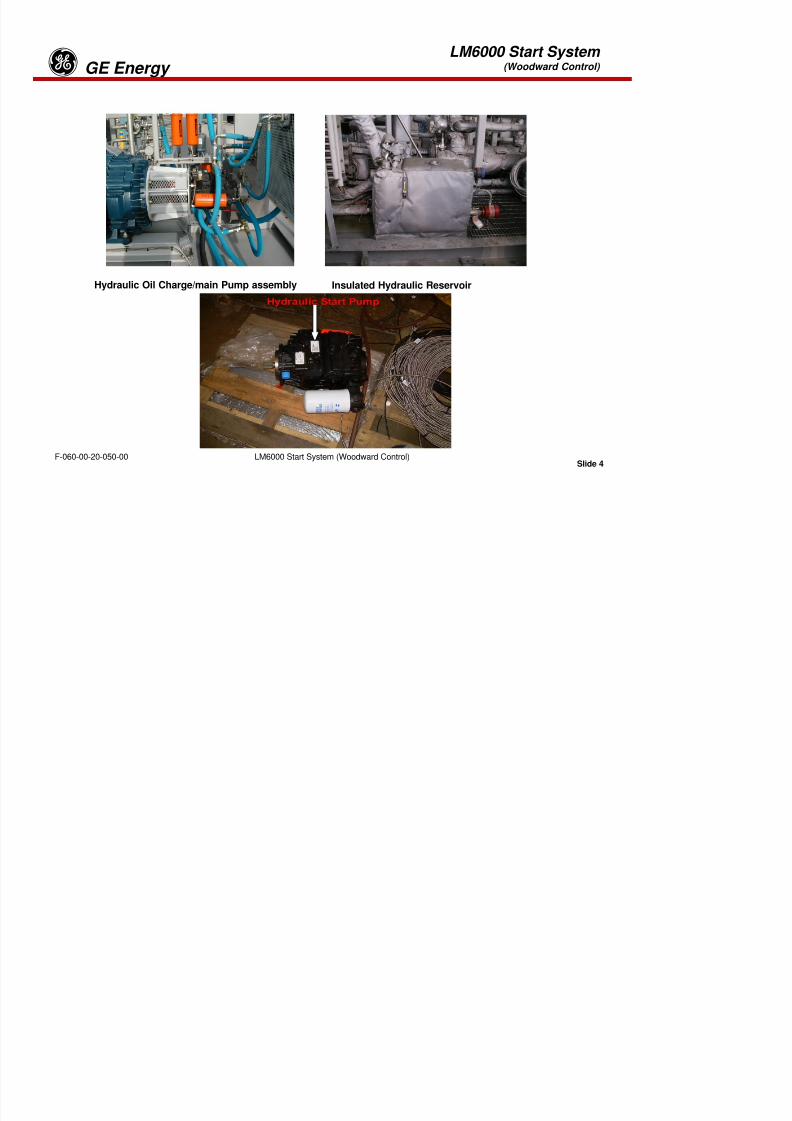
8/18/2019 71777896 - LM6000 Package Familiarization & Operations.pdf
http://slidepdf.com/reader/full/71777896-lm6000-package-familiarization-operationspdf 239/786
LM6000 Start System(Woodward Control) GE Energyg
Cooler Pump

8/18/2019 71777896 - LM6000 Package Familiarization & Operations.pdf
http://slidepdf.com/reader/full/71777896-lm6000-package-familiarization-operationspdf 240/786
Slide 2LM6000 Start System (Woodward Control)F-060-00-20-050-00
LM6000 Start System(Woodward Control) GE Energyg
SYSTEM OVERVIEW
The illustration above is a simplified diagram of the LM6000 Hydraulic Starter System. For complete, site-
specific layout, instrumentation and settings, please refer to F&ID XXX232.The LM6000 hydraulic start system supplies hydraulic pressure to the hydraulic starter motor. Thispressure is used to rotate the HP compressor during low-speed crank, high-speed crank, and start. Thestarter system is also utilized to perform offline water wash cycles and to crank engine during certainCDLO/FSWM shutdowns.
The charge pump takes suction from the hydraulic oil reservoir and discharges the hydraulic oil to thesuction side of the main pump, providing a positive suction for the main pump. The main pump
discharges the oil at 5200 psig (35,853 kPag) at a flow rate of 56 gal/min (212 L/ min). The oil from themain pump is piped to the hydraulic starter motor on the accessory gearbox of the gas turbine. The oilpressure hydraulic starter motor, in turn, rotates the HP compressor through the accessory gearbox. Mostof the oil from the hydraulic starter motor returns to the suction side of the main pump, but oil from thepump casing drains, then flows, through a return line to the temperature control valve. When the return oilis cool, the temperature valve sends the oil directly to the reservoir. When oil heats up during operation,the valve diverts oil to a fin-fan cooler and then to the reservoir.
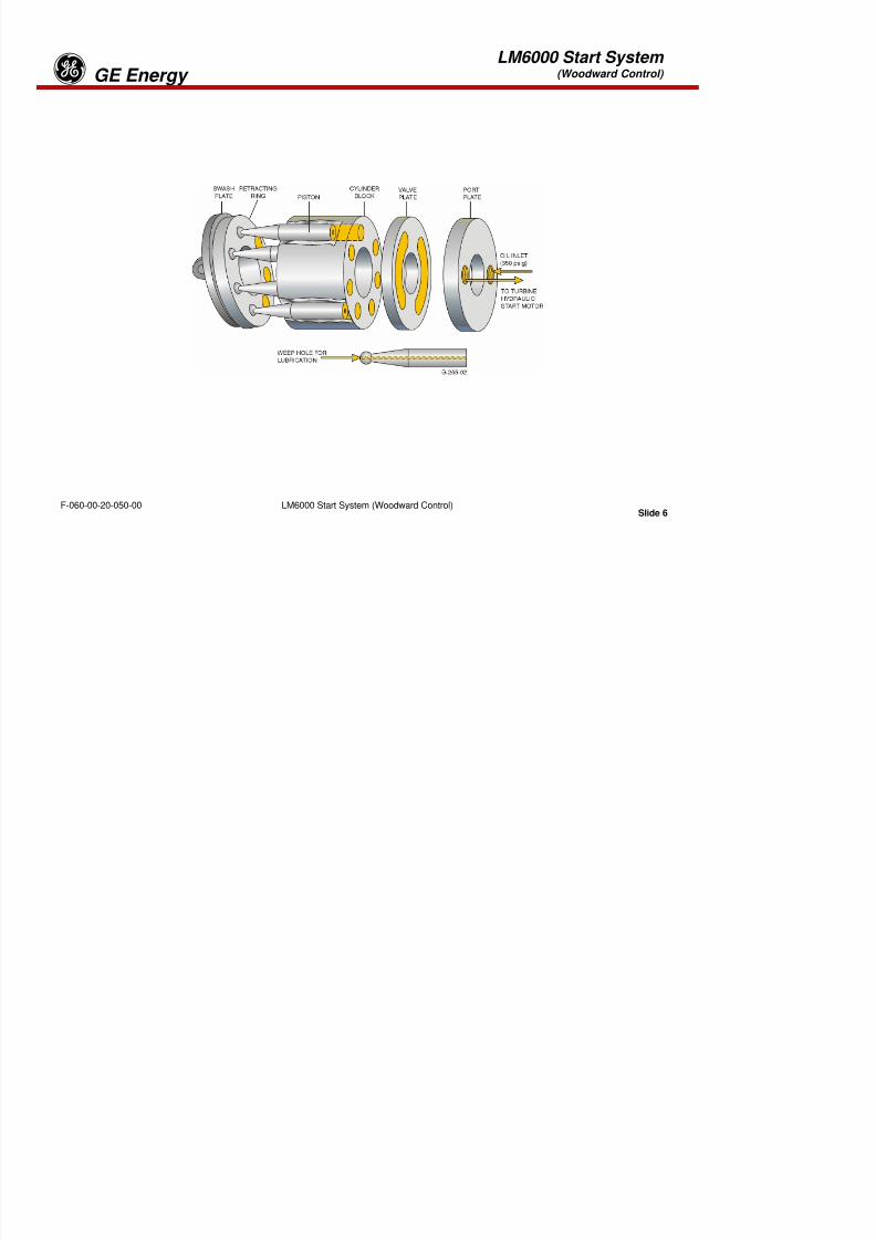
8/18/2019 71777896 - LM6000 Package Familiarization & Operations.pdf
http://slidepdf.com/reader/full/71777896-lm6000-package-familiarization-operationspdf 241/786
Slide 3LM6000 Start System (Woodward Control)F-060-00-20-050-00
the valve diverts oil to a fin fan cooler and then to the reservoir.
The hydraulic cooler fan pump is mounted on the end of the hydraulic pump assembly. This pump takessuction from the reservoir and discharges the oil to the hydraulic fan motor on the fin fan oil cooler. Thedischarge from the motor returns to the hydraulic oil reservoir.
LM6000 Start System(Woodward Control) GE Energyg
Hydraulic Oil Charge/main Pump assembly Insulated Hydraulic Reservoir

8/18/2019 71777896 - LM6000 Package Familiarization & Operations.pdf
http://slidepdf.com/reader/full/71777896-lm6000-package-familiarization-operationspdf 242/786
Slide 4LM6000 Start System (Woodward Control)F-060-00-20-050-00
LM6000 Start System(Woodward Control) GE EnergygHydraulic Oil Reservoir
The hydraulic oil reservoir is stainless steel. The reservoir is located on the auxiliary skid and has a 40 gal(151 L) capacity. The reservoir has local indication of level and a reservoir heater, which keeps lube oil
temperature in the reservoir to at least 90 °F (32 °C). The reservoir also has a level switch, a temperatureswitch, and a suction strainer, which will bypass the strainer at 3 psid (20.6 kPad), located inside thereservoir.
Hydraulic Oil Charge Pump
The charge pump is one of three pumps in the hydraulic pump assembly. The charge pump takes suction
from the hydraulic oil reservoir and discharges the hydraulic oil at 350 psig (2413 kPag) at a flow rate of 12gal/min (45 L/min) to the charge pump filter.
Charge Pump Filter
The charge pump filter is a “spin on” type single stage filter. The filter has a visual indicator to show filterditi Th filt h i h b l th t ill b i il d th filt if diff ti l
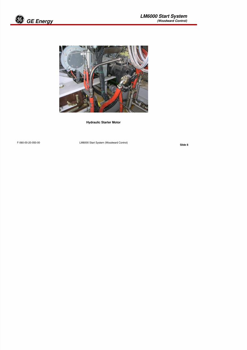
8/18/2019 71777896 - LM6000 Package Familiarization & Operations.pdf
http://slidepdf.com/reader/full/71777896-lm6000-package-familiarization-operationspdf 243/786
Slide 5LM6000 Start System (Woodward Control)F-060-00-20-050-00
condition. The filter housing has a bypass valve that will open, bypassing oil around the filter if differential
pressure across the filter reaches 50 psid (344.6 kPad).
LM6000 Start System(Woodward Control) GE Energyg

8/18/2019 71777896 - LM6000 Package Familiarization & Operations.pdf
http://slidepdf.com/reader/full/71777896-lm6000-package-familiarization-operationspdf 244/786
Slide 6LM6000 Start System (Woodward Control)F-060-00-20-050-00
LM6000 Start System(Woodward Control) GE EnergygMain Hydraulic Oil Pump
The main hydraulic starter pump, located on the starter skid, is driven by a three-phase, constant-speed,
AC electric motor. The hydraulic starter pump has a variable swash plate, whose angle is controlled bysoftware logic signals from the turbine control panel (TCP). The signals are applied to a solenoid operatedvalve (SOV) on the hydraulic starter pump assembly. The hydraulic starter pump supplies hydraulic fluidunder high pressure to the turbine starter motor. As the hydraulic starter pump’s swash plate angle isincreased or decreased, more or less hydraulic fluid under pressure is applied to the pistons in the turbinestarter motor, thereby increasing or decreasing the revolutions per minute (rpm) of the starter and theturbine engine.
Fluid pressure from the hydraulic starter pump is applied to pistons in the turbine starter motor causingthe motor to rotate.
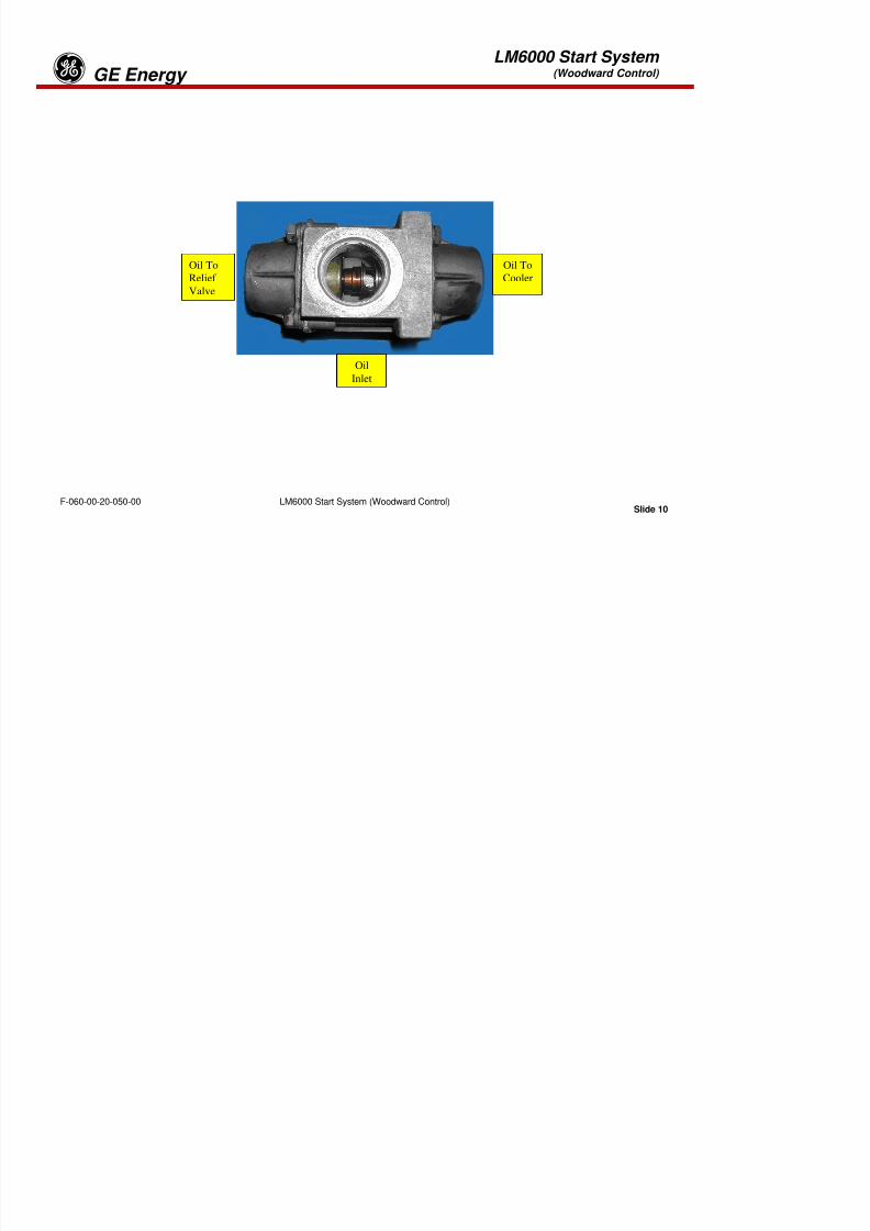
8/18/2019 71777896 - LM6000 Package Familiarization & Operations.pdf
http://slidepdf.com/reader/full/71777896-lm6000-package-familiarization-operationspdf 245/786
Slide 7LM6000 Start System (Woodward Control)F-060-00-20-050-00
LM6000 Start System(Woodward Control) GE Energyg

8/18/2019 71777896 - LM6000 Package Familiarization & Operations.pdf
http://slidepdf.com/reader/full/71777896-lm6000-package-familiarization-operationspdf 246/786
Slide 8LM6000 Start System (Woodward Control)F-060-00-20-050-00
Hydraulic Starter Motor
LM6000 Start System(Woodward Control) GE Energyg
Hydraulic Starter Motor
The hydraulic starter motor, located on the auxiliary gearbox of the LM6000, is driven by hydraulic fluidunder high pressure from the main hydraulic oil pump. The hydraulic starter motor has a fixed angle swashplate with movable pistons. The high-pressure fluid forces the pistons to move within the cylinder, causingthe motor to rotate.
Low Pressure Return Oil Filter
The low-pressure return oil filter is a “spin-on” type single-stage filter. The filter has a visual indicator toshow filter condition. The filter housing has a bypass valve that will open, bypassing oil around the filter ifdifferential pressure across the filter reaches 25 psid (172.3 kPad).

8/18/2019 71777896 - LM6000 Package Familiarization & Operations.pdf
http://slidepdf.com/reader/full/71777896-lm6000-package-familiarization-operationspdf 247/786
Slide 9LM6000 Start System (Woodward Control)F-060-00-20-050-00
LM6000 Start System(Woodward Control) GE Energyg
Oil To
Cooler
Oil To
Relief
Valve

8/18/2019 71777896 - LM6000 Package Familiarization & Operations.pdf
http://slidepdf.com/reader/full/71777896-lm6000-package-familiarization-operationspdf 248/786
Slide 10LM6000 Start System (Woodward Control)F-060-00-20-050-00
Oil
Inlet
LM6000 Start System(Woodward Control) GE EnergygTemperature Control Valve
The temperature control valve regulates hydraulic oil return temperature by bypassing some oil around thelube oil cooler. The valve opens when the oil heats during operation and diverts the oil through the Fin-
Fan cooler to the reservoir. Temperature control valve is set at 120°F (49°C).
Hydraulic Oil Cooler Pump
The cooler pump is a gear type pump coupled to the main pump assembly which is driven by the electricmotor. It draws suction from the reservoir and pressurizes a hydraulic fan motor in the hydraulic oil cooler.
Hydraulic Oil Cooler Pump Discharge Relief Valve
The hydraulic oil cooler pump discharge relief valve protects the hydraulic cooler pumps from over-pressurization, by discharging excess pressure back to the reservoir. The relief valve is set at 1200 psid.
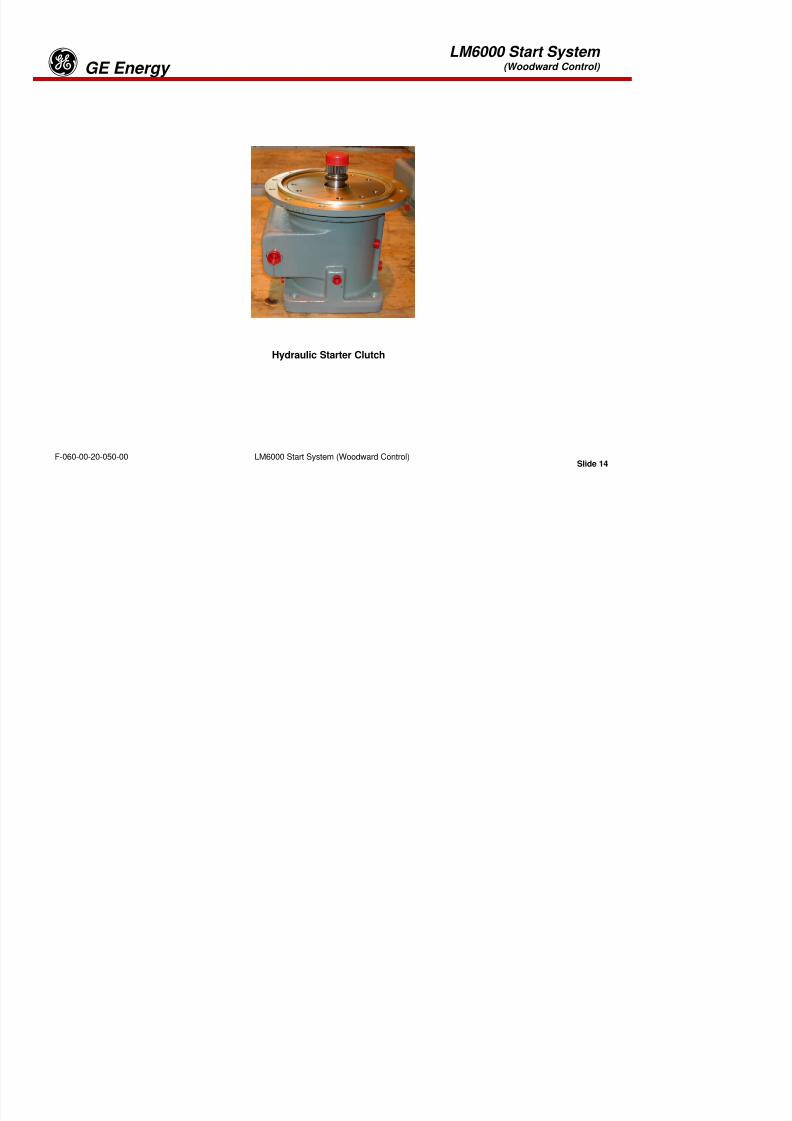
8/18/2019 71777896 - LM6000 Package Familiarization & Operations.pdf
http://slidepdf.com/reader/full/71777896-lm6000-package-familiarization-operationspdf 249/786
Slide 11LM6000 Start System (Woodward Control)F-060-00-20-050-00
LM6000 Start System(Woodward Control) GE Energyg
8/18/2019 71777896 - LM6000 Package Familiarization & Operations.pdf
http://slidepdf.com/reader/full/71777896-lm6000-package-familiarization-operationspdf 250/786
Slide 12LM6000 Start System (Woodward Control)F-060-00-20-050-00
Hydraulic Oil Cooler (Electric)
LM6000 Start System(Woodward Control) GE Energyg
Hydraulic Oil Cooler
A fin fan type cooler cools the hydraulic oil. The fan for the cooler is powered by a hydraulic motor whichin return rotates a five blade fixed pitch fan assembly. The hydraulic motor is powered by pressure fromthe hydraulic oil cooler pump.
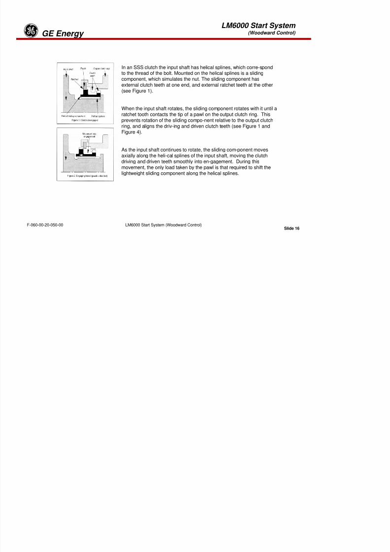
8/18/2019 71777896 - LM6000 Package Familiarization & Operations.pdf
http://slidepdf.com/reader/full/71777896-lm6000-package-familiarization-operationspdf 251/786
Slide 13LM6000 Start System (Woodward Control)F-060-00-20-050-00
LM6000 Start System(Woodward Control) GE Energyg

8/18/2019 71777896 - LM6000 Package Familiarization & Operations.pdf
http://slidepdf.com/reader/full/71777896-lm6000-package-familiarization-operationspdf 252/786
Slide 14LM6000 Start System (Woodward Control)F-060-00-20-050-00
Hydraulic Starter Clutch
LM6000 Start System(Woodward Control) GE Energyg
Centrifugal Starting Clutch
In the starting motor output shaft a centrifugal clutch allows engagement of the starting motor to the gasturbine generator at the beginning of the start-up sequence, and disengagement as soon as the HP runsfaster than the starting motor. At 4500 rpm’s XN 2.5 speed the control system will signal a shutdown ofthe hydraulic start motor. For proper clutch operation, the oil flow to the clutch should be continuouslycontrolled to a minimum of .5 qt/minute (.47 L/min) and to a maximum of 1.25 qt/minute (1.18 L/min). Anorifice plate controls this oil flow. This clutch is also referred to as an overriding or overrunning clutch.
At standstill of the gas turbine generator and the starting motor, the pawls of the centrifugal clutch engage
in the gear on the starting motor output shaft. Weak plate springs push the pawls in the gear teeth. Assoon as the starting motor begins to run, it will drive the HP shaft. The pawls tend to move outwards dueto centrifugal force, but as long as the starting motor supplies torque to the HP rotor, the claws will stayengaged by friction.
At approximately 4500 rpm the control system will shut down the starting motor. This will cause thetorque to reverse and, immediately, the claws will disengage.

8/18/2019 71777896 - LM6000 Package Familiarization & Operations.pdf
http://slidepdf.com/reader/full/71777896-lm6000-package-familiarization-operationspdf 253/786
Slide 15LM6000 Start System (Woodward Control)F-060-00-20-050-00
When during the shutdown sequence the gas generator runs down to standstill, the centrifugal force onthe pawls will gradually diminish, allowing the weak springs to bring the claws to the starting motor gear.As soon as the HP shaft speed is below 1000 rpm, the gas turbine may be started again. The springforce in the clutch then overrides the centrifugal force of the claws, allowing full engagement of the claws.
LM6000 Start System(Woodward Control) GE Energyg
In an SSS clutch the input shaft has helical splines, which corre-spond
to the thread of the bolt. Mounted on the helical splines is a slidingcomponent, which simulates the nut. The sliding component hasexternal clutch teeth at one end, and external ratchet teeth at the other(see Figure 1).
When the input shaft rotates, the sliding component rotates with it until a
ratchet tooth contacts the tip of a pawl on the output clutch ring. Thisprevents rotation of the sliding compo-nent relative to the output clutchring, and aligns the driv-ing and driven clutch teeth (see Figure 1 andFigure 4).
As the input shaft continues to rotate, the sliding com-ponent movesaxially along the heli-cal splines of the input shaft, moving the clutch

8/18/2019 71777896 - LM6000 Package Familiarization & Operations.pdf
http://slidepdf.com/reader/full/71777896-lm6000-package-familiarization-operationspdf 254/786
Slide 16LM6000 Start System (Woodward Control)F-060-00-20-050-00
driving and driven teeth smoothly into en-gagement. During thismovement, the only load taken by the pawl is that required to shift thelightweight sliding component along the helical splines.
LM6000 Start System(Woodward Control) GE Energyg
Basic SSS Clutch Principle
The initials SSS denote the 'Synchro-Self-Shifting' action of the clutch, whereby the clutch driving anddriven teeth are phased and then automatically shifted axially into engagement when rotating at preciselythe same speed. The clutch disengages as soon as the input speed slows down relative to the outputspeed.
The basic operating principle of the SSS clutch can be compared to the action of a nut screwed onto abolt. If the bolt rotates with the nut free, the nut will rotate with the bolt. If the nut is prevented from rotatingwhile the bolt continues to turn, the nut will move in a straight line along the bolt.
8/18/2019 71777896 - LM6000 Package Familiarization & Operations.pdf
http://slidepdf.com/reader/full/71777896-lm6000-package-familiarization-operationspdf 255/786
Slide 17LM6000 Start System (Woodward Control)F-060-00-20-050-00
LM6000 Start System(Woodward Control) GE Energyg
As the sliding component moves along the input shaft, the pawl passes
out of contact with the ratchet tooth, allow-ing the driving teeth to comeinto flank contact with the driven teeth and continues the engaging travel(see Figure 2).
Driving torque from the input shaft will only be transmitted when the slidingcomponent completes its travel by con-tacting an end stop on the inputshaft, with the clutch teeth fully engaged and the pawls unloaded (seeFigure 3). When a nut is screwed against the head of a bolt, no external
thrust is produced. Similarly, when the sliding component of an SSS clutchreaches its end stop and the clutch is transmitting driving torque, noexternal thrust loads are produced by the helical splines.
If the speed of the input shaft is reduced relative to the output shaft, thetorque on the helical splines will reverse.
Thi th lidi t t t t th di d iti
8/18/2019 71777896 - LM6000 Package Familiarization & Operations.pdf
http://slidepdf.com/reader/full/71777896-lm6000-package-familiarization-operationspdf 256/786
Slide 18LM6000 Start System (Woodward Control)F-060-00-20-050-00
This causes the sliding component to return to the disengaged positionand the clutch will overrun. At high overrunning speeds, pawl ratcheting isprevented by a combination of centrifugal and hydrodynamic effects actingon the pawls. The basic SSS clutch can operate continuously engaged oroverrunning at maxi-mum speed without wear occurring.
LM6000 Start System(Woodward Control) GE Energyg

8/18/2019 71777896 - LM6000 Package Familiarization & Operations.pdf
http://slidepdf.com/reader/full/71777896-lm6000-package-familiarization-operationspdf 257/786
Slide 19LM6000 Start System (Woodward Control)F-060-00-20-050-00
Hydraulic Start System HMI Screen
LM6000 Start System(Woodward Control) GE EnergygHydraulic Start System Review
1. The hydraulic starter system rotates the High Pressure Rotor to start the engine. What
causes the Low Pressure Rotor to Start Rotating?
2. Where is the hydraulic starter mounted on the gas turbine?
3. The hydraulic cooler bypass valve maintains the hydraulic fluid at 120 °F.
A. True B. False
4. As the pump swashplate angle is increased or decreased, more or less hydraulic pressureis applied to the turbine starter, thereby increasing or decreasing turbine rpms.
8/18/2019 71777896 - LM6000 Package Familiarization & Operations.pdf
http://slidepdf.com/reader/full/71777896-lm6000-package-familiarization-operationspdf 258/786
Slide 20LM6000 Start System (Woodward Control)F-060-00-20-050-00
A. True B. False
5. The engine's hydraulic starter receives electrical power from the motor control center.
A. True B. False
6. Name the 3 pumps on the hydraulic start motor?
LM6000 Start System(Woodward Control) GE Energyg
7. Explain the type of clutch on the LM6000 and its operation.
8. What protects the cooler from over pressurization?
9. If the temperature control valve should fail, oil is bypassed at _________ pressure.

8/18/2019 71777896 - LM6000 Package Familiarization & Operations.pdf
http://slidepdf.com/reader/full/71777896-lm6000-package-familiarization-operationspdf 259/786
Slide 21LM6000 Start System (Woodward Control)F-060-00-20-050-00
Tab 8

8/18/2019 71777896 - LM6000 Package Familiarization & Operations.pdf
http://slidepdf.com/reader/full/71777896-lm6000-package-familiarization-operationspdf 260/786
LM6000 Dual Fuel System (Woodward Control)
LM6000 DUAL FUEL SYSTEM
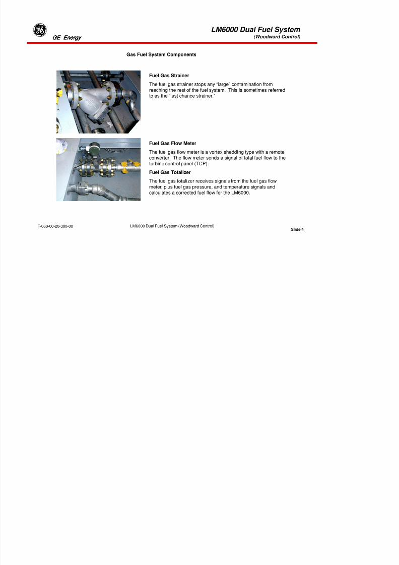
8/18/2019 71777896 - LM6000 Package Familiarization & Operations.pdf
http://slidepdf.com/reader/full/71777896-lm6000-package-familiarization-operationspdf 261/786
Slide 1F-060-00-20-300-00 LM6000 Dual Fuel System (Woodward Control)
LM6000 Dual Fuel System (Woodward Control)
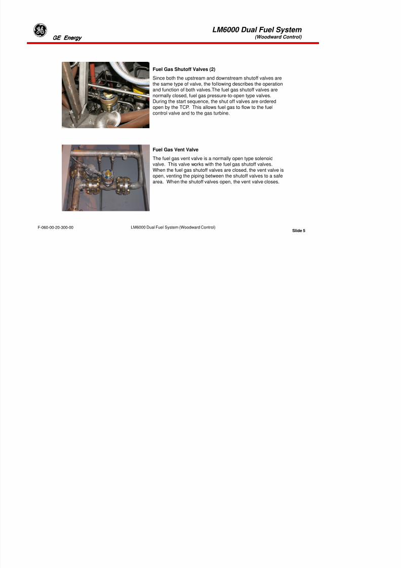
8/18/2019 71777896 - LM6000 Package Familiarization & Operations.pdf
http://slidepdf.com/reader/full/71777896-lm6000-package-familiarization-operationspdf 262/786
Slide 2F-060-00-20-300-00 LM6000 Dual Fuel System (Woodward Control)
LM6000 Dual Fuel System (Woodward Control)
FUEL GAS SYSTEM
The fuel gas system provides fuel gas in sufficient amounts to run the LM6000 through the full scale ofoperations.
The fuel gas enters the enclosure base at the following conditions:
•250°F (121°C) Max.
•675± 20 Psig (4655±138 kPag)
•Filtered to 3 micron
The fuel gas enters the enclosure and passes by or through the following:
•A 100-mesh “Y” type strainer
•The fuel flow element, which sends a signal to the turbine control panel
•The upstream fuel gas shut off valve
•The fuel gas control valve

8/18/2019 71777896 - LM6000 Package Familiarization & Operations.pdf
http://slidepdf.com/reader/full/71777896-lm6000-package-familiarization-operationspdf 263/786
Slide 3F-060-00-20-300-00 LM6000 Dual Fuel System (Woodward Control)
•The downstream fuel gas shut off valve
•The fuel gas manifold
•The fuel nozzles

8/18/2019 71777896 - LM6000 Package Familiarization & Operations.pdf
http://slidepdf.com/reader/full/71777896-lm6000-package-familiarization-operationspdf 264/786

8/18/2019 71777896 - LM6000 Package Familiarization & Operations.pdf
http://slidepdf.com/reader/full/71777896-lm6000-package-familiarization-operationspdf 265/786
LM6000 Dual Fuel System (Woodward Control)
Dual Fuel Nozzle
Mounting Flange
Liquid Fuel
Water Injection
Gas Fuel
Combustion AirGas Fuel
Liquid Fuel/Water
Fuel Nozzle Tip

8/18/2019 71777896 - LM6000 Package Familiarization & Operations.pdf
http://slidepdf.com/reader/full/71777896-lm6000-package-familiarization-operationspdf 266/786
Slide 6F-060-00-20-300-00 LM6000 Dual Fuel System (Woodward Control)
p
LM6000 Dual Fuel System (Woodward Control)
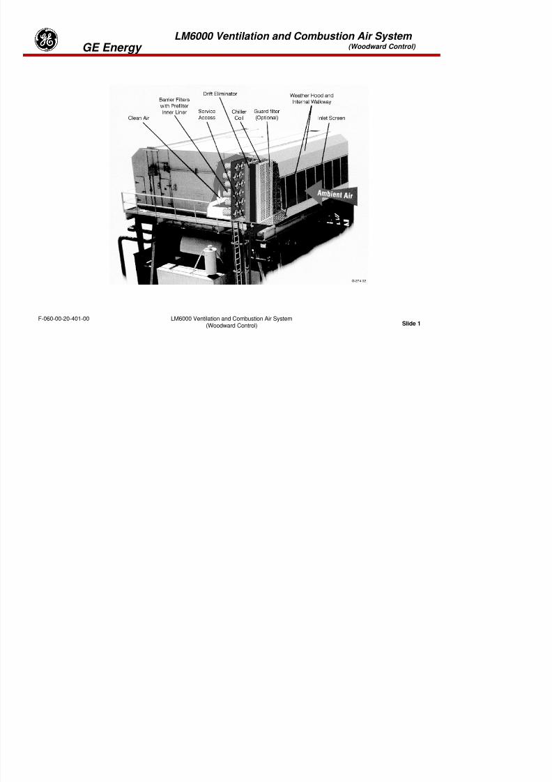
8/18/2019 71777896 - LM6000 Package Familiarization & Operations.pdf
http://slidepdf.com/reader/full/71777896-lm6000-package-familiarization-operationspdf 267/786
Slide 7F-060-00-20-300-00 LM6000 Dual Fuel System (Woodward Control)
LM6000 Dual Fuel System (Woodward Control)
3101 GAS VALVE AND EM35 ELECTRIC ACTUATOR DESCRIPTION.
3101 Gas ValveThe 3101 Gas Valve is a stainless steel valve capable of metering gas flow between 50 and 40,000 pph
(pounds per hour). The valve is designed to bolt into a two (2)-inch line. The valve design is a rotarymetering sleeve and shoe-type-throttling valve. The valve shoe is spring and pressure loaded against themetering port to minimize leakage and to self-clean the metering port. Metering port area is determinedby input shaft positioning from the actuator. The valve has an internal spring to return the valve to theminimum fuel position in the event of a power loss to the actuator.
The 3101 gas valve has redundant seals on all dynamic sealing surfaces. Between these two seals is anoverboard vent which vents any gasses that leak past the first seal to safe vent location. The use of aninner-seal vent prevents the second dynamic seal from seeing any differential pressure and thus offersprotection against the leakage of gasses from the valve into the surrounding ambient atmosphere. Thevalve design incorporates an inlet guide tube to condition the inlet flow and to direct any gascontaminants through the metering port, minimizing any accumulation in the valve hosing. The meteringsleeve support bearings are positively sealed from the gas. Internal valve parts are made of throughhardened stainless steel.
CAUTION

8/18/2019 71777896 - LM6000 Package Familiarization & Operations.pdf
http://slidepdf.com/reader/full/71777896-lm6000-package-familiarization-operationspdf 268/786
Slide 8F-060-00-20-300-00 LM6000 Dual Fuel System (Woodward Control)
The valve has mechanical stop screws installed in the valve flange. The customer must not adjust thesestops. If these stops interfere with the valve operating region or the electrical stops, it will cause theEM35 driver to trip out on overcurrent.
Tab 9
8/18/2019 71777896 - LM6000 Package Familiarization & Operations.pdf
http://slidepdf.com/reader/full/71777896-lm6000-package-familiarization-operationspdf 269/786
LM6000 Ventilation and Combustion Air System (Woodward Control) GE Energy
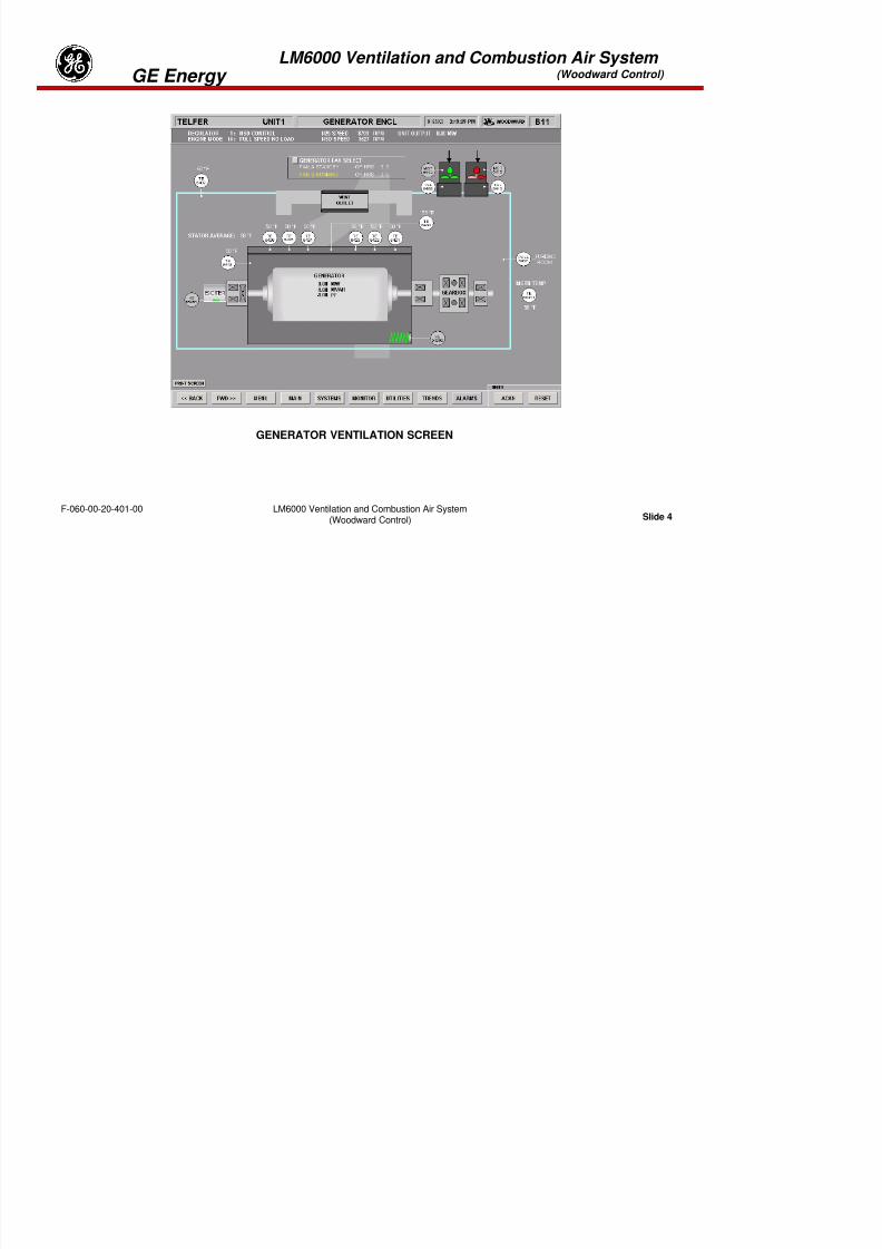
8/18/2019 71777896 - LM6000 Package Familiarization & Operations.pdf
http://slidepdf.com/reader/full/71777896-lm6000-package-familiarization-operationspdf 270/786
Slide 1LM6000 Ventilation and Combustion Air System
(Woodward Control)F-060-00-20-401-00
LM6000 Ventilation and Combustion Air System (Woodward Control) GE Energy

8/18/2019 71777896 - LM6000 Package Familiarization & Operations.pdf
http://slidepdf.com/reader/full/71777896-lm6000-package-familiarization-operationspdf 271/786
Slide 2LM6000 Ventilation and Combustion Air System
(Woodward Control)F-060-00-20-401-00
VENTILATION & COMBUSTION AIR SYSTEM SCREEN #1
LM6000 Ventilation and Combustion Air System (Woodward Control) GE Energy
SYSTEM OVERVIEW
The ventilation and combustion air system can be divided into the following three (3) sub-systems; the gasturbine enclosure ventilation air system, the generator enclosure ventilation air system and the gas turbinecombustion air system.
GAS TURBINE ENCLOSURE VENTILATION AIR SYSTEM
The gas turbine ventilation air system provides the gas turbine enclosure with sufficient ventilation air tocool the gas turbine exterior and the inside of the enclosure.
Air flows through the filters in the filter house. From the filter house the air flows down the ductwork intothe gas turbine enclosure. Next the air is removed from the gas turbine enclosure by theenclosure/exhaust fans and is discharged back to the atmosphere. This maintains the gas turbine
enclosure under a negative pressure.
GAS TURBINE COMBUSTION AIR SYSTEM
The combustion air system provides a sufficient amount of combustion air (approximately 230,000 scfm(6512.8 scmm) for the LM6000 to operate at all required operating levels. Air enters the filter house andflows through the chiller / heater coils. Then the air flows through barrier filters, drift eliminator located inthe filter house, down the duct to the inlet bellmouth screen (last chance) and into the inlet volute. The
inlet volute turns the airflow from a downward flow to a horizontal flow and into the LM6000 gas turbine.From the LM6000 the exhaust gases pass thru outlet guide vanes which will evenly distribute the exhaust
th th h t ll t b f di h d b k i t th t h

8/18/2019 71777896 - LM6000 Package Familiarization & Operations.pdf
http://slidepdf.com/reader/full/71777896-lm6000-package-familiarization-operationspdf 272/786
Slide 3LM6000 Ventilation and Combustion Air System
(Woodward Control)F-060-00-20-401-00
gases thru the exhaust collector before discharged back into the atmosphere.
LM6000 Ventilation and Combustion Air System (Woodward Control) GE Energy
8/18/2019 71777896 - LM6000 Package Familiarization & Operations.pdf
http://slidepdf.com/reader/full/71777896-lm6000-package-familiarization-operationspdf 273/786
Slide 4LM6000 Ventilation and Combustion Air System
(Woodward Control)F-060-00-20-401-00
GENERATOR VENTILATION SCREEN
LM6000 Ventilation and Combustion Air System (Woodward Control) GE Energy
GENERATOR ENCLOSURE VENTILATION AIR SYSTEM
The generator ventilation air system provides the generator enclosure with sufficient ventilation air to coolthe generator and the inside of the generator enclosure. Air flows through the filters in the filter house.From the filter house the air is drawn into one of the generator cooling fans and is discharged into thegenerator enclosure. From the generator enclosure the air flows into each end of the generator. On thedriven end of the generator the air flows along the rotor shaft and is then discharged into the generatorexhaust and back to the atmosphere. On both ends of the generator rotor shaft are mounted fans thatdraw air from the generator enclosure. Most of the air flows along the rotor shaft and is then dischargedinto the generator exhaust. A portion of incoming air flows across the exciter and is then discharged backinto the generator air-cooling stream.
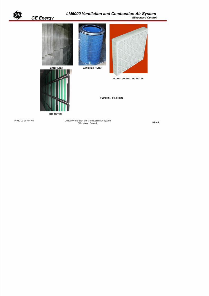
8/18/2019 71777896 - LM6000 Package Familiarization & Operations.pdf
http://slidepdf.com/reader/full/71777896-lm6000-package-familiarization-operationspdf 274/786
Slide 5LM6000 Ventilation and Combustion Air System
(Woodward Control)F-060-00-20-401-00
LM6000 Ventilation and Combustion Air System (Woodward Control) GE Energy

8/18/2019 71777896 - LM6000 Package Familiarization & Operations.pdf
http://slidepdf.com/reader/full/71777896-lm6000-package-familiarization-operationspdf 275/786
Slide 6LM6000 Ventilation and Combustion Air System
(Woodward Control)F-060-00-20-401-00
Typical Filter House
LM6000 Ventilation and Combustion Air System (Woodward Control) GE Energy
Filter House
Air enters the filter house and flows through various customer selected filtration, cooling and anti-icing
equipment. The air flows through the barrier filters in the filter house, down ducts to the combustion airinlet volute and to the two enclosures for cooling. There are numerous options the customer may selectdepending on the operating environment. They are:
Filtration
Barrier filters (high efficiency filter) may consist of a canister or bag type filter element. All units will have
barrier filters as these are the primary filter for the unit.
Inlet screens are a large mesh, stainless steel screen mounted on the opening to the filter house toprevent birds and large sized garbage from entering the filter house.
Guard filters are a disposable pre-filter used to extend the operating life of the barrier filter. They are easyto change out and less expensive than the barrier filters.
Drift eliminators are moisture separators designed to remove water droplets from the airflow.

8/18/2019 71777896 - LM6000 Package Familiarization & Operations.pdf
http://slidepdf.com/reader/full/71777896-lm6000-package-familiarization-operationspdf 276/786
Slide 7LM6000 Ventilation and Combustion Air System
(Woodward Control)F-060-00-20-401-00
LM6000 Ventilation and Combustion Air System (Woodward Control) GE Energy
BAG FILTER CANISTER FILTER
GUARD (PREFILTER) FILTER
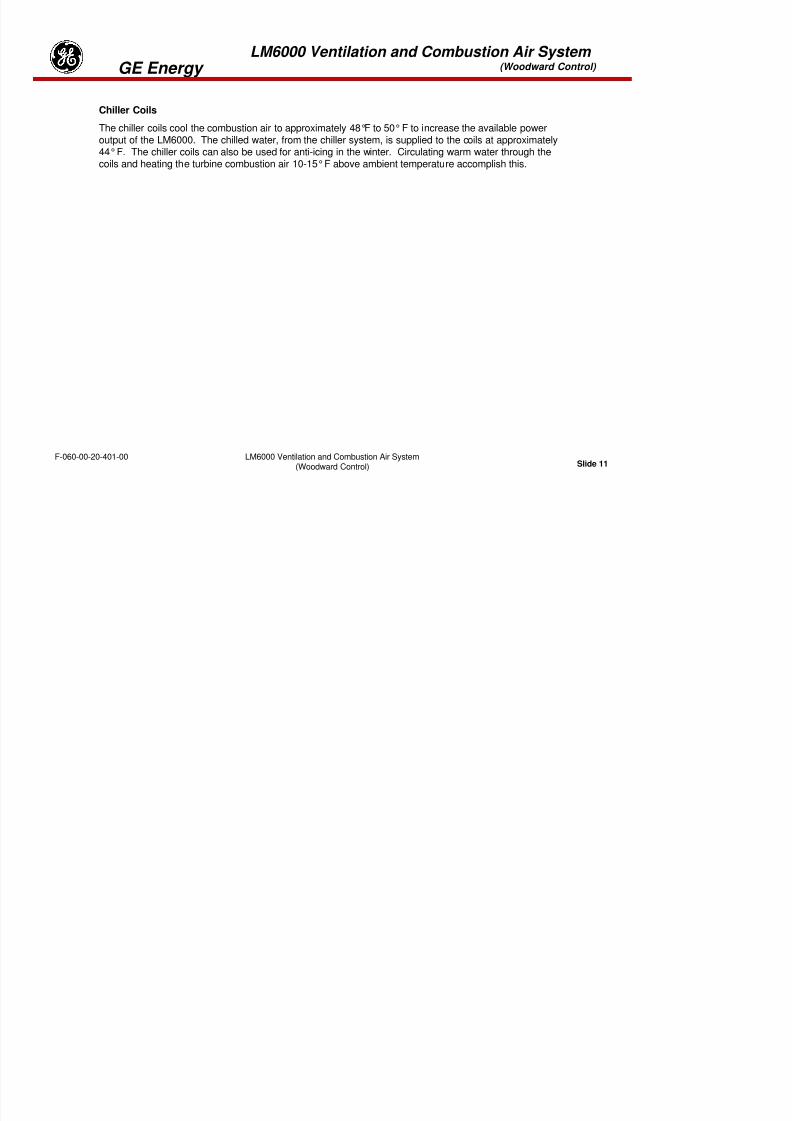
8/18/2019 71777896 - LM6000 Package Familiarization & Operations.pdf
http://slidepdf.com/reader/full/71777896-lm6000-package-familiarization-operationspdf 277/786
Slide 8LM6000 Ventilation and Combustion Air System
(Woodward Control)F-060-00-20-401-00
BOX FILTER
TYPICAL FILTERS
LM6000 Ventilation and Combustion Air System (Woodward Control) GE Energy
GUARD (PREFILTER) FILTER
The guard filter (optional) may be used in areas where there is a large concentration of airborne
contaminates. The guard filter is an disposable filter utilized to catch a majority of the airbornecontaminates which will prolong the life of the more expensive barrier filters. When differential pressureincreases to an alarm state, the filter assembly will be replaced and the old filter disposed.
BARRIER FILTERS
The barrier filters, which are made of a composite type material, are high efficiency media which filters theincoming ventilation air to remove any solid contamination.
The canister type media has a pre-filter that inserts into the canister to help prolong the life of the canister.
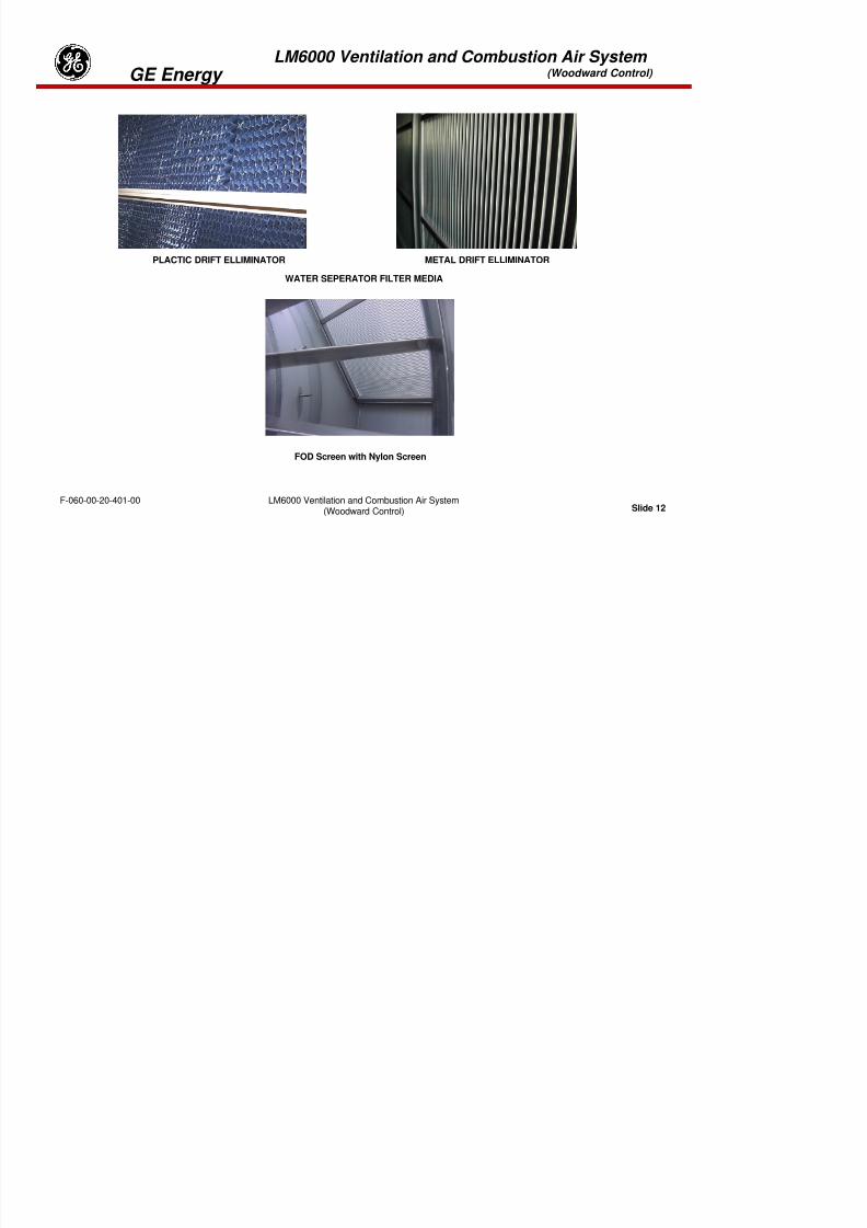
8/18/2019 71777896 - LM6000 Package Familiarization & Operations.pdf
http://slidepdf.com/reader/full/71777896-lm6000-package-familiarization-operationspdf 278/786
Slide 9LM6000 Ventilation and Combustion Air System
(Woodward Control)F-060-00-20-401-00
LM6000 Ventilation and Combustion Air System (Woodward Control) GE Energy

8/18/2019 71777896 - LM6000 Package Familiarization & Operations.pdf
http://slidepdf.com/reader/full/71777896-lm6000-package-familiarization-operationspdf 279/786
Slide 10LM6000 Ventilation and Combustion Air System
(Woodward Control)F-060-00-20-401-00
LM6000 Ventilation and Combustion Air System (Woodward Control) GE Energy
Chiller Coils
The chiller coils cool the combustion air to approximately 48°F to 50° F to increase the available poweroutput of the LM6000. The chilled water, from the chiller system, is supplied to the coils at approximately
44° F. The chiller coils can also be used for anti-icing in the winter. Circulating warm water through thecoils and heating the turbine combustion air 10-15° F above ambient temperature accomplish this.
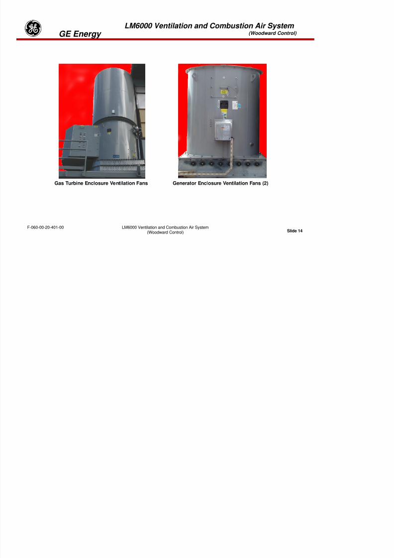
8/18/2019 71777896 - LM6000 Package Familiarization & Operations.pdf
http://slidepdf.com/reader/full/71777896-lm6000-package-familiarization-operationspdf 280/786
Slide 11LM6000 Ventilation and Combustion Air System
(Woodward Control)F-060-00-20-401-00
LM6000 Ventilation and Combustion Air System (Woodward Control) GE Energy
PLACTIC DRIFT ELLIMINATOR METAL DRIFT ELLIMINATORWATER SEPERATOR FILTER MEDIA
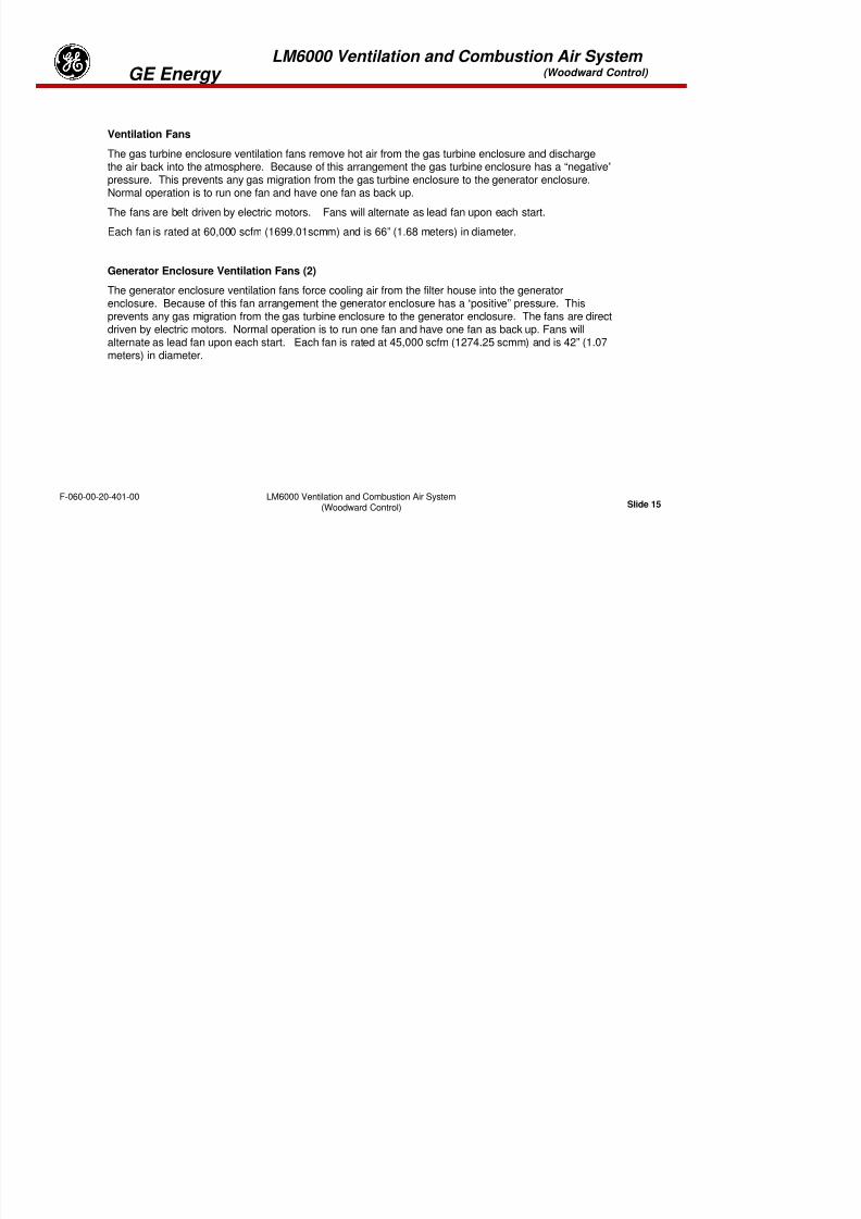
8/18/2019 71777896 - LM6000 Package Familiarization & Operations.pdf
http://slidepdf.com/reader/full/71777896-lm6000-package-familiarization-operationspdf 281/786
Slide 12LM6000 Ventilation and Combustion Air System
(Woodward Control)F-060-00-20-401-00
FOD Screen with Nylon Screen
LM6000 Ventilation and Combustion Air System (Woodward Control) GE Energy
DRIFT ELIMINATOR
The drift eliminator is a water separating media which changes the direction of the airflow, causes anymoisture to “drop out” of the combustion air. The collected moisture is then drained off.
FOD Screen
This is the “last chance” filtration of the combustion air before it enters the LM6000. The screen is acrossthe inlet bellmouth. The screen is rated at 1200 micron and is supported by a stainless steel mesh. Thisscreen is designed to catch any small foreign objects. The FOD screen has two sizes of synthetic filtersthat can be installed to increase protection.
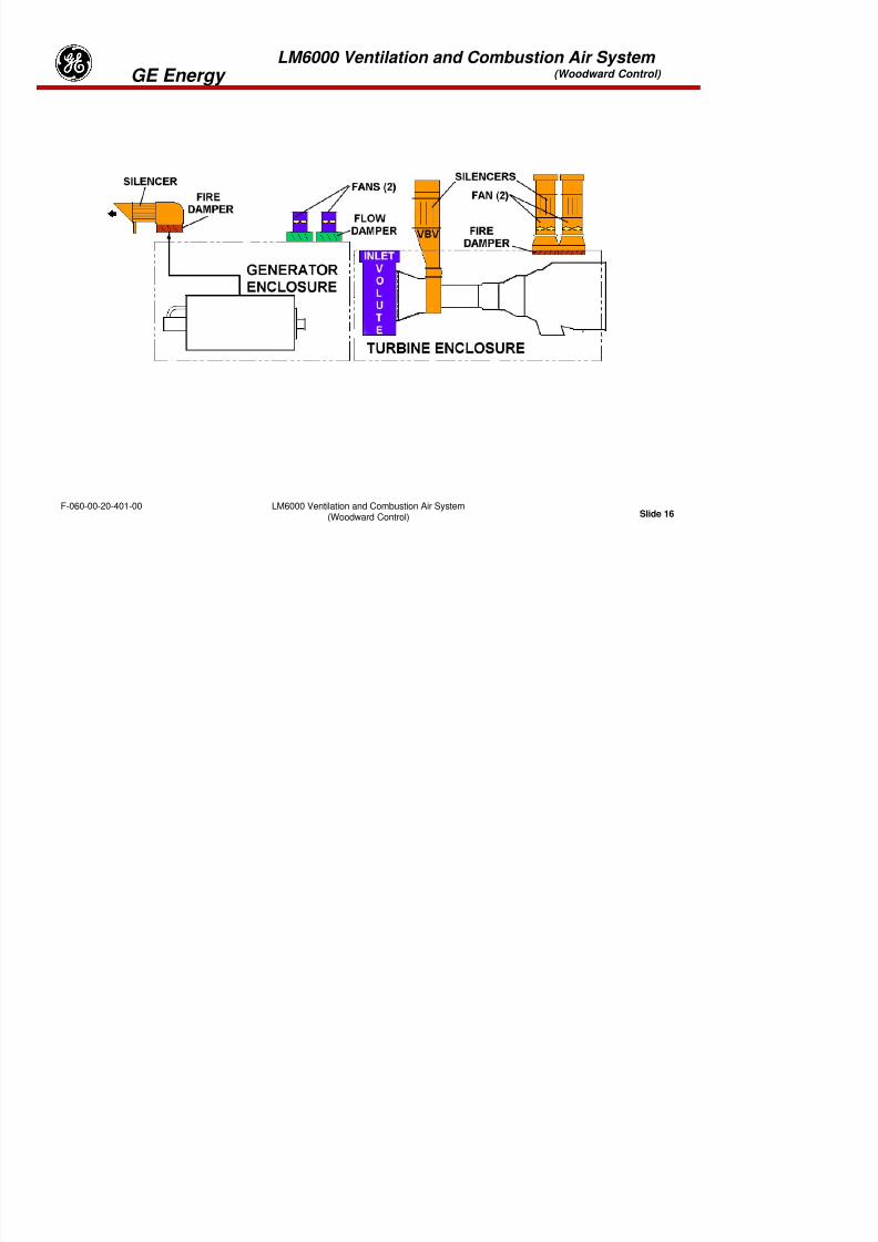
8/18/2019 71777896 - LM6000 Package Familiarization & Operations.pdf
http://slidepdf.com/reader/full/71777896-lm6000-package-familiarization-operationspdf 282/786
Slide 13LM6000 Ventilation and Combustion Air System
(Woodward Control)F-060-00-20-401-00
LM6000 Ventilation and Combustion Air System (Woodward Control) GE Energy
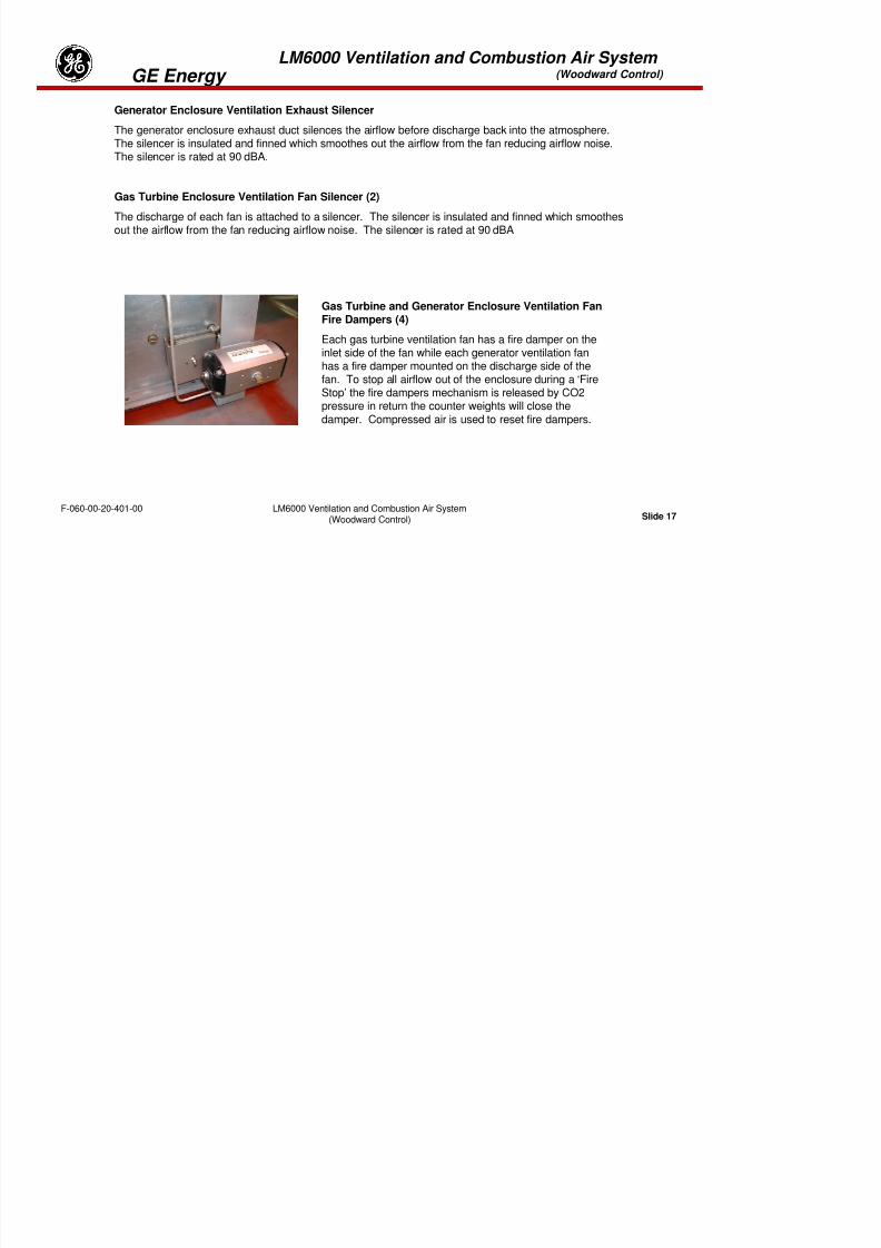
8/18/2019 71777896 - LM6000 Package Familiarization & Operations.pdf
http://slidepdf.com/reader/full/71777896-lm6000-package-familiarization-operationspdf 283/786
Slide 14LM6000 Ventilation and Combustion Air System
(Woodward Control)F-060-00-20-401-00
Gas Turbine Enclosure Ventilation Fans Generator Enclosure Ventilation Fans (2)
LM6000 Ventilation and Combustion Air System (Woodward Control) GE Energy
Ventilation Fans
The gas turbine enclosure ventilation fans remove hot air from the gas turbine enclosure and discharge
the air back into the atmosphere. Because of this arrangement the gas turbine enclosure has a “negative”pressure. This prevents any gas migration from the gas turbine enclosure to the generator enclosure.Normal operation is to run one fan and have one fan as back up.
The fans are belt driven by electric motors. Fans will alternate as lead fan upon each start.
Each fan is rated at 60,000 scfm (1699.01scmm) and is 66” (1.68 meters) in diameter.
Generator Enclosure Ventilation Fans (2)
The generator enclosure ventilation fans force cooling air from the filter house into the generatorenclosure. Because of this fan arrangement the generator enclosure has a “positive” pressure. Thisprevents any gas migration from the gas turbine enclosure to the generator enclosure. The fans are directdriven by electric motors. Normal operation is to run one fan and have one fan as back up. Fans willalternate as lead fan upon each start. Each fan is rated at 45,000 scfm (1274.25 scmm) and is 42” (1.07
meters) in diameter.
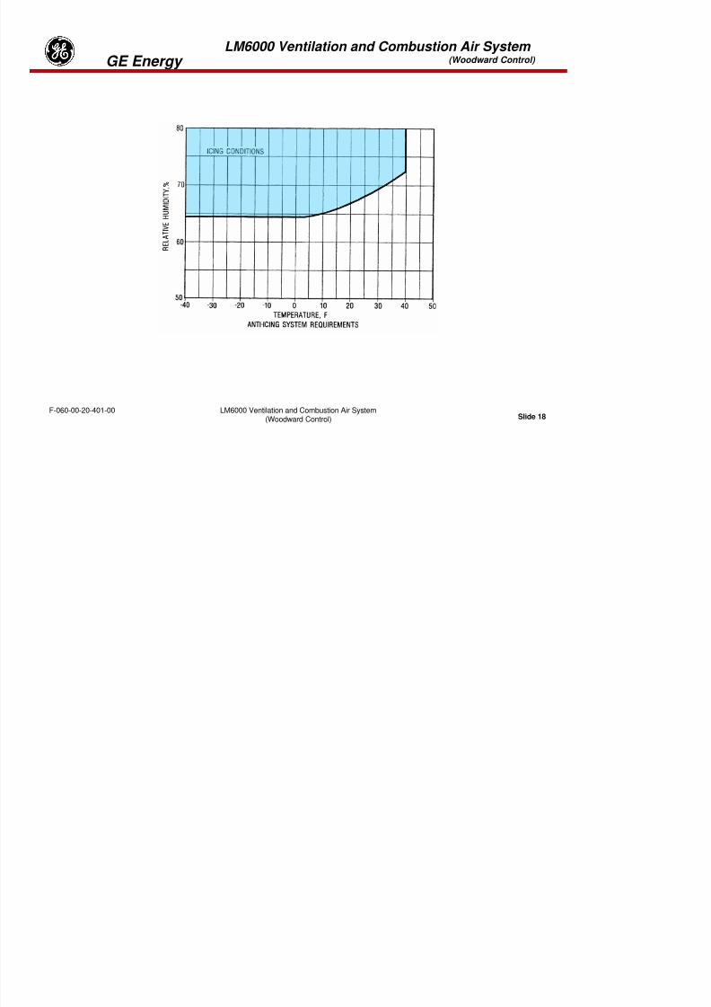
8/18/2019 71777896 - LM6000 Package Familiarization & Operations.pdf
http://slidepdf.com/reader/full/71777896-lm6000-package-familiarization-operationspdf 284/786
Slide 15LM6000 Ventilation and Combustion Air System
(Woodward Control)F-060-00-20-401-00
LM6000 Ventilation and Combustion Air System (Woodward Control) GE Energy

8/18/2019 71777896 - LM6000 Package Familiarization & Operations.pdf
http://slidepdf.com/reader/full/71777896-lm6000-package-familiarization-operationspdf 285/786
Slide 16LM6000 Ventilation and Combustion Air System
(Woodward Control)F-060-00-20-401-00
8/18/2019 71777896 - LM6000 Package Familiarization & Operations.pdf
http://slidepdf.com/reader/full/71777896-lm6000-package-familiarization-operationspdf 286/786
LM6000 Ventilation and Combustion Air System (Woodward Control) GE Energy

8/18/2019 71777896 - LM6000 Package Familiarization & Operations.pdf
http://slidepdf.com/reader/full/71777896-lm6000-package-familiarization-operationspdf 287/786
Slide 18LM6000 Ventilation and Combustion Air System
(Woodward Control)F-060-00-20-401-00
LM6000 Ventilation and Combustion Air System (Woodward Control) GE Energy
Icing Conditions and Anti-Icing Systems
Note from the table above that icing conditions are possible at temperatures above 32 degF (0 degC).
Temperature protection is provided in the form of an alarm that is generated at 43 degF (6 degC). Thisalarm alerts the operator to the possibility of icing conditions. In the event of such an alarm, it is theoperator’s responsibility to check the relative humidity and determine if anti-icing measures should betaken.
Anti-icing requires heating of the inlet air. This may be accomplished by one of several means. Insystems equipped with chiller coils, it is possible to circulate heated fluid (typically glycol) through thechiller coils. In some systems, there are ducts which allow turbine enclosure exhaust air to be
introduced to the inlet for anti-icing. In other system, turbine exhaust is used to heat inlet air. Note thatturbine exhaust is never introduced directly into the turbine inlet air.

8/18/2019 71777896 - LM6000 Package Familiarization & Operations.pdf
http://slidepdf.com/reader/full/71777896-lm6000-package-familiarization-operationspdf 288/786
Slide 19LM6000 Ventilation and Combustion Air System
(Woodward Control)F-060-00-20-401-00
LM6000 Ventilation and Combustion Air System (Woodward Control) GE Energy
Ventilation and Combustion Air System Review
1. Three benefits of the air filtration system are:
1) ________________________________________
2) ________________________________________
3) ________________________________________
2. In summer, operators often cool the combustion air entering the turbine inlet, using mechanical
chillers, how will cooling the air improve performance?
3. Combustion and enclosure ventilation air passages are separated in the filter house ____.
A. To provide added filtration of combustion air
B. To provide cooling or heating of combustion air without cooling or heating enclosureventilation air
C. To allow more effective silencing of airflow into the engine
D. Develop negative pressure between the enclosures

8/18/2019 71777896 - LM6000 Package Familiarization & Operations.pdf
http://slidepdf.com/reader/full/71777896-lm6000-package-familiarization-operationspdf 289/786
Slide 20LM6000 Ventilation and Combustion Air System
(Woodward Control)F-060-00-20-401-00
4. The turbine enclosure is maintained at a ______________ pressure during operation.
A. Negative B. Positive
LM6000 Ventilation and Combustion Air System (Woodward Control) GE Energy
5. During normal operation, both of the turbine enclosure ventilation fans are running.
A. True B. False
6. The engine air inlet silencer reduces noise by reducing combustion air velocity.
A. True B. False
7. The ventilation fans pressure the generator enclosure and vent the turbine enclosure, creating a
pressure-differential between the enclosures. How does this arrangement help improve safety?
8. All the ventilation air is filtered to the same degree as the combustion air. Why is this filtrationimportant to maintenance of the generator?
9. What is the tag number for the Enclosure differential switch?
10. How many inlet temperature gages are located on the air inlet housing?

8/18/2019 71777896 - LM6000 Package Familiarization & Operations.pdf
http://slidepdf.com/reader/full/71777896-lm6000-package-familiarization-operationspdf 290/786
Slide 21LM6000 Ventilation and Combustion Air System
(Woodward Control)F-060-00-20-401-00
LM6000 Ventilation and Combustion Air System (Woodward Control) GE Energy
11. Are the exhaust fans for the turbine and inlet fans for the generator rated the same?
12. How can ice build-up be prevented from the air inlet housing?
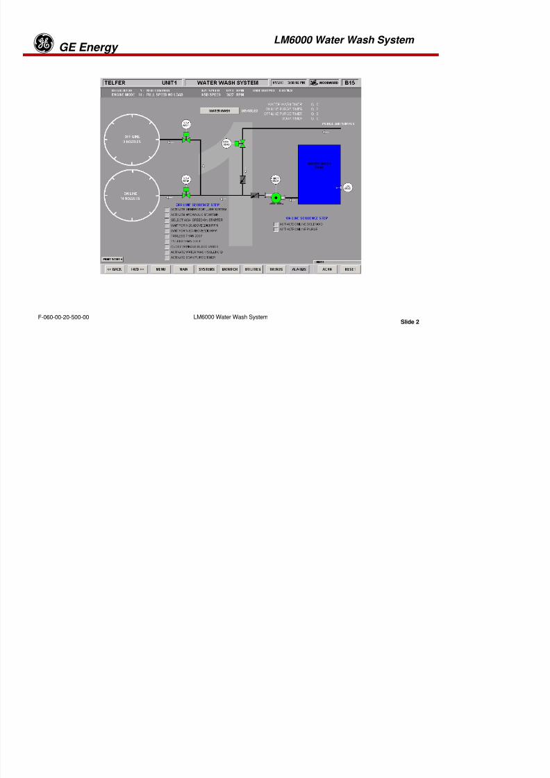
8/18/2019 71777896 - LM6000 Package Familiarization & Operations.pdf
http://slidepdf.com/reader/full/71777896-lm6000-package-familiarization-operationspdf 291/786
Slide 22LM6000 Ventilation and Combustion Air System
(Woodward Control)F-060-00-20-401-00
Tab 10

8/18/2019 71777896 - LM6000 Package Familiarization & Operations.pdf
http://slidepdf.com/reader/full/71777896-lm6000-package-familiarization-operationspdf 292/786
LM6000 Water Wash System GE Energyg
8/18/2019 71777896 - LM6000 Package Familiarization & Operations.pdf
http://slidepdf.com/reader/full/71777896-lm6000-package-familiarization-operationspdf 293/786
Slide 1LM6000 Water Wash SystemF-060-00-20-500-00
LM6000 Water Wash System GE Energyg

8/18/2019 71777896 - LM6000 Package Familiarization & Operations.pdf
http://slidepdf.com/reader/full/71777896-lm6000-package-familiarization-operationspdf 294/786
Slide 2LM6000 Water Wash SystemF-060-00-20-500-00
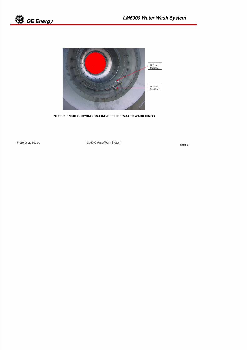
8/18/2019 71777896 - LM6000 Package Familiarization & Operations.pdf
http://slidepdf.com/reader/full/71777896-lm6000-package-familiarization-operationspdf 295/786
LM6000 Water Wash System GE Energy
gMethods of Detection
•Visual
•Performance Monitoring
VISUAL INSPECTION
The best method for detecting a fouled compressor is visual inspection. This involves shutting the unitdown, removing the inlet plenum inspection hatch, and visually inspecting the compressor inlet, bellmouth,inlet guide vanes, and early stage blading. If there are any deposits, including dust or oily deposits thatcan be wiped or scraped off these areas, the compressor is fouled sufficiently to affect performance. The
initial inspection reveals whether the deposits are oily or dry. For oily deposits, a water-detergent wash isrequired, followed by clean water rinses. The source of the oil should be located and corrected beforecleaning to prevent recurrence of the fouling.
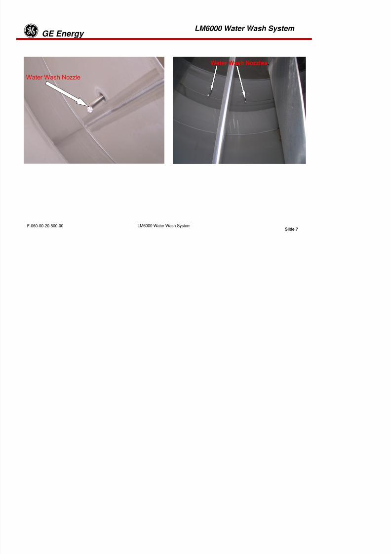
8/18/2019 71777896 - LM6000 Package Familiarization & Operations.pdf
http://slidepdf.com/reader/full/71777896-lm6000-package-familiarization-operationspdf 296/786
Slide 4LM6000 Water Wash SystemF-060-00-20-500-00
LM6000 Water Wash System GE Energy
gPERFORMANCE MONITORING
A second method for detecting a fouled compressor is performance monitoring. Performance monitoringinvolves obtaining gas turbine data on a routine basis, which in turn is compared to baseline data tomonitor trends in the performance of the gas turbine.
The performance data is obtained by running the unit at a steady base load and recording output,exhaust temperatures, inlet air temperatures, barometric pressure, compressor discharge pressure andtemperature, and fuel consumption. The data should be taken carefully with the unit warmed up. Ifperformance analysis indicates compressor fouling, it should be verified by a visual inspection.
Washing and rinsing solutions are mixed in a holding reservoir and pumped into nozzle rings in theengine air inlet under controlled pressure and flow rates for optimum cleaning. Operators are responsiblefor charging the reservoir and initiating the washing and rinsing cycles. Software logic then operates thepump and valve controls, based upon operator mode selections and engine safety permissives.
Following the release of washing and rinsing solutions into the engine, a software- controlled air purge ofthe nozzles prevents contamination or blockages in the feed nozzles.

8/18/2019 71777896 - LM6000 Package Familiarization & Operations.pdf
http://slidepdf.com/reader/full/71777896-lm6000-package-familiarization-operationspdf 297/786
Slide 5LM6000 Water Wash SystemF-060-00-20-500-00
LM6000 Water Wash System GE Energy
g
On Line
Manifold
Off Line
Manifold
INLET PLENIUM SHOWING ON-LINE/OFF-LINE WATER WASH RINGS
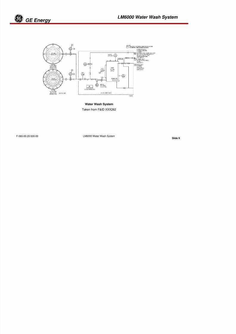
8/18/2019 71777896 - LM6000 Package Familiarization & Operations.pdf
http://slidepdf.com/reader/full/71777896-lm6000-package-familiarization-operationspdf 298/786
Slide 6LM6000 Water Wash SystemF-060-00-20-500-00
LM6000 Water Wash System GE Energy
g
8/18/2019 71777896 - LM6000 Package Familiarization & Operations.pdf
http://slidepdf.com/reader/full/71777896-lm6000-package-familiarization-operationspdf 299/786
Slide 7LM6000 Water Wash SystemF-060-00-20-500-00
LM6000 Water Wash System GE Energy
g
OFF-LINE and ON-LINE WASH MODES
Off-Line
Most effective
Uses de-min water/detergent solution
On-Line
Not as effective as Off-Line procedure
May extend intervals between Off-Line washes
Uses de-min water only
8/18/2019 71777896 - LM6000 Package Familiarization & Operations.pdf
http://slidepdf.com/reader/full/71777896-lm6000-package-familiarization-operationspdf 300/786
Slide 8LM6000 Water Wash SystemF-060-00-20-500-00
LM6000 Water Wash System GE Energy
g
Water Wash System
Taken from F&ID XXX262
8/18/2019 71777896 - LM6000 Package Familiarization & Operations.pdf
http://slidepdf.com/reader/full/71777896-lm6000-package-familiarization-operationspdf 301/786
Slide 9LM6000 Water Wash SystemF-060-00-20-500-00
LM6000 Water Wash System GE Energy
gThe flow and instrument diagram illustrates separate nozzle rings in the engine inlet for on-line and off-linecleaning. Droplet size is larger in the off-line ring, allowing greater flow volume than is permissible whenthe engine is running. Smaller droplets are necessary in on-line operation to avoid blocking compressorblades at speeds above core idle. Cold weather operations require the addition of anti-freeze. Be sure to
check manufacturer’s information for mixing of soap solution and antifreeze to ensure compatibility.
Operators initiate washing by closing the tank drain, discharge, and water fill lines. After introducingrecommended chemical amounts, the chemical inlet valve is closed and the water fill valve is opened.The engine manufacturer recommends 150 °F–180 °F (66 °C – 82 °C) water temperature. For unitswithout the tank heating option, water preheating is recommended. A sight gage is provided to avoidoverfilling.
After charging the reservoir, WASH mode is selected on the turbine control panel (TCP). If the engine isnot running, an off-line sequence is enabled. The START pushbutton on the water wash skid activates thesequence as follows:

8/18/2019 71777896 - LM6000 Package Familiarization & Operations.pdf
http://slidepdf.com/reader/full/71777896-lm6000-package-familiarization-operationspdf 302/786
Slide 10LM6000 Water Wash SystemF-060-00-20-500-00
LM6000 Water Wash System GE Energy
gNOTE: Conduct all Water Wash procedures IAW WP 4014.
Off-Line Water Wash
Remove the following sensor lines on the engine as close to the sensing point as possible. Tape off, withnon-residue tape, the sensor side of the line.
Ø P2 Low Pressure Compressor Inlet Pressure
Ø P2.5 High Pressure Compressor Inlet Pressure
Ø P3 High Pressure Compressor Discharge Pressure
Ø P4.8 Low Pressure Turbine Inlet Pressure
1. A WASH MODE ACTIVE status message is presented on the operator’s CRT screen.
2. The generator alternating current (AC) lube oil and jacking pumps are activated. (In systemsgenerating 50 Hz power, a gearbox turning motor is activated.)
3. The electric motor driving the centrifugal water pump is activated, pressurizing the water lines to
both cleaning ring manifolds.4. The permissives listed below are verified for off-line washing.
1. XN25 > 1700 rpm
2. XN2 > 200 rpm
8/18/2019 71777896 - LM6000 Package Familiarization & Operations.pdf
http://slidepdf.com/reader/full/71777896-lm6000-package-familiarization-operationspdf 303/786
Slide 11LM6000 Water Wash SystemF-060-00-20-500-00
p
3. T48 average < 200 °F (93 °C)
4. Crank mode flag not set (unit in WASH mode)
LM6000 Water Wash System GE Energy
g
5. The off-line ring manifold feed solenoid valve is opened, allowing flow from the reservoir.
6. Both manifold solenoid valves are opened and the air purge valve is opened for approximately 1minute.
7. A WASH COMPLETE operator message is presented and the skid-mounted pushbutton is reset.
Off-line rinse is performed identically, except chemicals are not added to the water tank before pressingthe WATER WASH pushbutton.
Off-line reservoir empty time is approximately 10 minutes.

8/18/2019 71777896 - LM6000 Package Familiarization & Operations.pdf
http://slidepdf.com/reader/full/71777896-lm6000-package-familiarization-operationspdf 304/786
Slide 12LM6000 Water Wash SystemF-060-00-20-500-00
LM6000 Water Wash System GE Energy
gOn-Line Water Wash
The permissives listed below are verified for on-line washing:
•Engine loading ³1.5 MW
•XNSD > 3585 rpm
•XN25 > 8000 rpm
Operator messages indicate which permissives are not met in off-line or on-line modes. On-line reservoirempty time is approximately 13 minutes.
Washing or rinsing can be terminated before the reservoir level switch closes by pressing the skid-mounted pushbutton a second time.
NOTE: All waste water from water washing is to be disposed of in accordance with the localenvironmental standards.
NOTE: During water wash approximately 10 percent of the water and cleaning solution will leak through
8/18/2019 71777896 - LM6000 Package Familiarization & Operations.pdf
http://slidepdf.com/reader/full/71777896-lm6000-package-familiarization-operationspdf 305/786
Slide 13LM6000 Water Wash SystemF-060-00-20-500-00
NOTE: During water wash, approximately 10 percent of the water and cleaning solution will leak throughthe engine casing and openings to the exterior of the engine.
LM6000 Water Wash System
GE Energyg
Features of the water wash system include the following:
Vent with 40-micron filter in the reservoir fill cap
•Filters at each ring manifold inlet
•Pressure indicator in the manifold feed line (the pressure should read in the 80–120 psig range)
•Analog flow rate indicator in the manifold feed line (normal flow rates are 5–8 gpm)
•Pressure regulator valve upstream of the flow rate indicator, allowing adjustment of flow rate
The following liquids detergents are available for crank/soak compressor cleaning:
•B&B 3100 (Crank/Soak clean only)
•Ardrox 6322
•RMC Turbine/Engine Cleaner (Rivenaes)
•Rochem Fyrewash
•ZOK 271.A
In freezing weather, mix one of the agents below with the cleaning solution mixtures:
I l Al h l

8/18/2019 71777896 - LM6000 Package Familiarization & Operations.pdf
http://slidepdf.com/reader/full/71777896-lm6000-package-familiarization-operationspdf 306/786
Slide 14LM6000 Water Wash SystemF-060-00-20-500-00
•Isopropyl Alcohol
•Acetone
LM6000 Water Wash System
GE Energyg
Compressor Water Wash System Review
1. Compressor cleaning is carried out periodically to ____.
A. Improve combustion airflow efficiencyB. Improve fuel use efficiency
C. Decrease T.3 at the same power settings
D. All of the above
E. None of the above
2 Distilled water is used for water wash to prevent corrosive buildup from contaminated water.
A. True B. False
3. How is excess water removed from the turbine exhaust case?
4. Lack of distilled water rinses will leave undesirable deposits on the engine compressor blades.
A. True B. False
5. Off-line water wash may not be initiated until surface temperature of the gas turbine is less than

8/18/2019 71777896 - LM6000 Package Familiarization & Operations.pdf
http://slidepdf.com/reader/full/71777896-lm6000-package-familiarization-operationspdf 307/786
Slide 15LM6000 Water Wash SystemF-060-00-20-500-00
______________ degrees Fahrenheit (degrees Centigrade).
6. Is it recommended to double the cleaning solution on excessively dirty compressors blades? Why?
LM6000 Water Wash System
GE Energyg
7. What is more effective, an online or off line water wash? Why.
8. Where are the water wash manifolds and nozzles located?
9. Why is preheating the solution prior to admitting it into the compressor sectionrecommended?
10. How are water wash chemicals disposed of?
11. The water wash fil ters are located_________________?
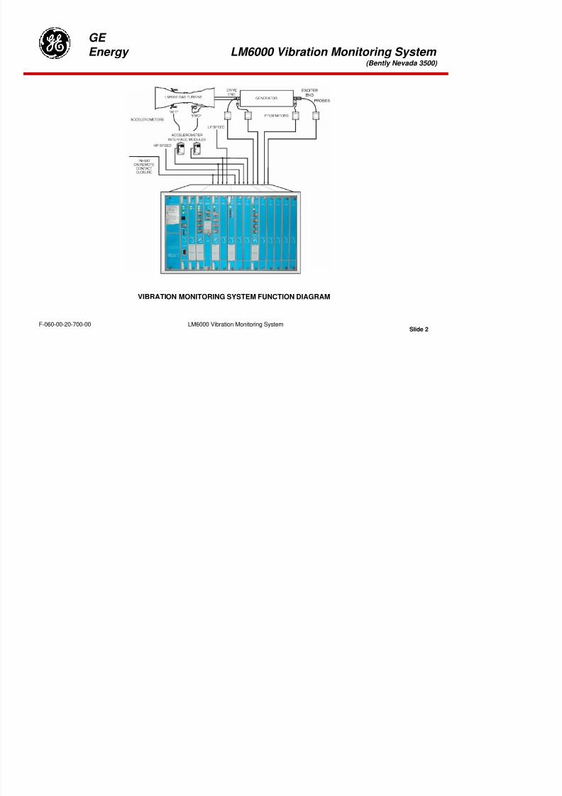
8/18/2019 71777896 - LM6000 Package Familiarization & Operations.pdf
http://slidepdf.com/reader/full/71777896-lm6000-package-familiarization-operationspdf 308/786
Slide 16LM6000 Water Wash SystemF-060-00-20-500-00
Tab 11

8/18/2019 71777896 - LM6000 Package Familiarization & Operations.pdf
http://slidepdf.com/reader/full/71777896-lm6000-package-familiarization-operationspdf 309/786
GE
Energy LM6000 Vibration Monitoring System (Bently Nevada 3500)
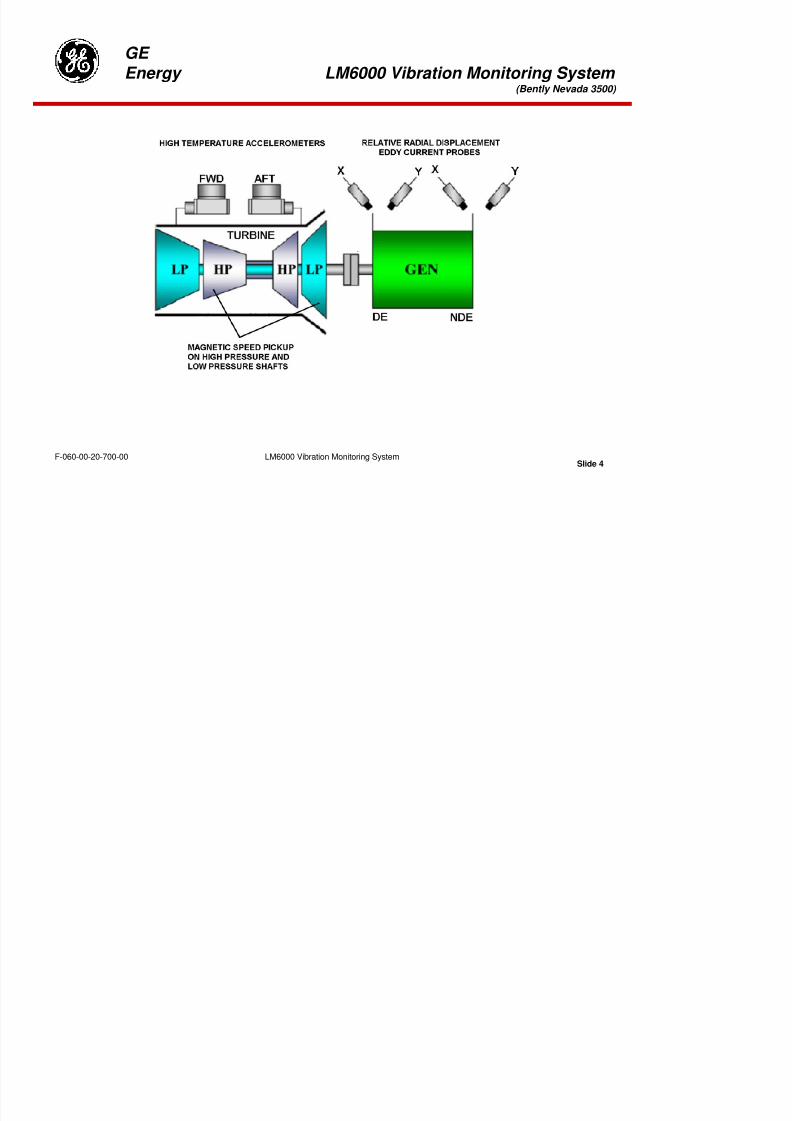
8/18/2019 71777896 - LM6000 Package Familiarization & Operations.pdf
http://slidepdf.com/reader/full/71777896-lm6000-package-familiarization-operationspdf 310/786
Slide 1LM6000 Vibration Monitoring SystemF-060-00-20-700-00
GE
Energy LM6000 Vibration Monitoring System (Bently Nevada 3500)
8/18/2019 71777896 - LM6000 Package Familiarization & Operations.pdf
http://slidepdf.com/reader/full/71777896-lm6000-package-familiarization-operationspdf 311/786
Slide 2LM6000 Vibration Monitoring SystemF-060-00-20-700-00
VIBRATION MONITORING SYSTEM FUNCTION DIAGRAM
GE
Energy LM6000 Vibration Monitoring System (Bently Nevada 3500)
PRIMARY PURPOSE OF THE 3500 IS TO PROVIDE:
Machinery protection by continuously comparing monitored parameters against configured alarm setpoints to drive alarms.
Essential machine management information for both operations and maintenance personnel.

8/18/2019 71777896 - LM6000 Package Familiarization & Operations.pdf
http://slidepdf.com/reader/full/71777896-lm6000-package-familiarization-operationspdf 312/786
Slide 3LM6000 Vibration Monitoring SystemF-060-00-20-700-00
GE
Energy LM6000 Vibration Monitoring System (Bently Nevada 3500)

8/18/2019 71777896 - LM6000 Package Familiarization & Operations.pdf
http://slidepdf.com/reader/full/71777896-lm6000-package-familiarization-operationspdf 313/786
Slide 4LM6000 Vibration Monitoring SystemF-060-00-20-700-00
GE
Energy LM6000 Vibration Monitoring System (Bently Nevada 3500)
VIBRATION MONITORING SYSTEM THEORY OF OPERATION
The vibration monitoring system produces vibration magnitude data with adjustable alarm and shutdownset points for engine and generator safety.
The previous figure illustrates the LM6000 engine and generator vibration sensors and electroniccomponents. Aft and forward engine accelerometers are installed on the turbine rear frame (TRF) andcompressor rear frame (CRF). These sensors produce complex electrical waveforms, resulting from thefrequency and amplitude of engine vibration. Interface modules, installed in relative close proximity to the
sensors, integrate 10-mV/g acceleration signals to obtain 100-mV/sec velocity signals for processing inmodules that plug into the control rack. The rack is mounted in the turbine control panel.
Tracking filters receive low-pressure turbine (LPT) and high-pressure turbine (HPT) velocity and speedsignals. The tracking filters present the velocity components associated with the two turbine speeds onfront panel displays.
In summary, four velocity signals are produced: one from each accelerometer, filtered at XN25 and atXNSD speeds. They are noted as follows:
•Engine (FWD) vibration velocity at (HPC) speed
•Engine (AFT) vibration velocity at (HPC) speed
•Engine (FWD) vibration velocity at power turbine (LPT/LPC) speed
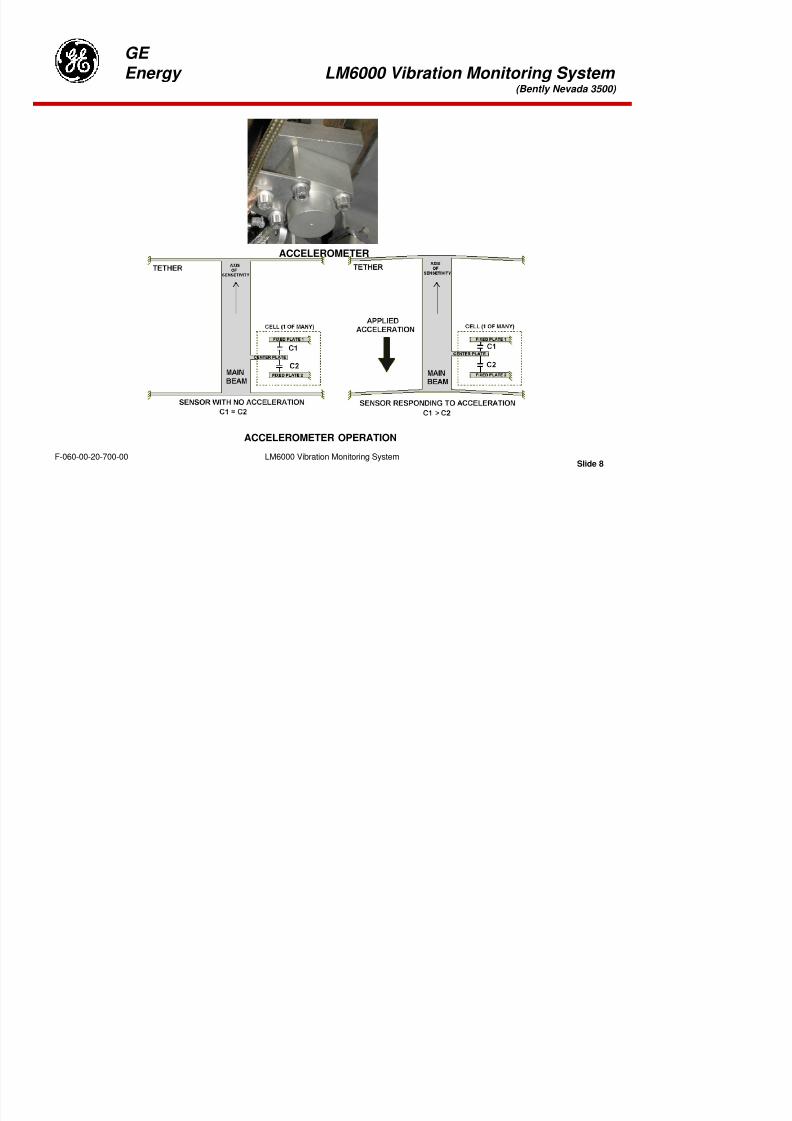
8/18/2019 71777896 - LM6000 Package Familiarization & Operations.pdf
http://slidepdf.com/reader/full/71777896-lm6000-package-familiarization-operationspdf 314/786
Slide 5LM6000 Vibration Monitoring SystemF-060-00-20-700-00
•Engine (FWD) vibration velocity at power turbine (LPT/LPC) speed
•Engine (AFT) vibration velocity at power turbine (LPT/LPC) speed
GE
Energy LM6000 Vibration Monitoring System (Bently Nevada 3500)

8/18/2019 71777896 - LM6000 Package Familiarization & Operations.pdf
http://slidepdf.com/reader/full/71777896-lm6000-package-familiarization-operationspdf 315/786
Slide 6LM6000 Vibration Monitoring SystemF-060-00-20-700-00
Generator Bearing Proximitors
GE
Energy LM6000 Vibration Monitoring System (Bently Nevada 3500)
Generator Bearing Proximitors
Proximitors are installed on the drive and non-drive ends of the generator drive shaft bearing housings, to measuredisplacement between the bearing housings and the generator shaft. Two proximitors are mounted on each bearinghousing perpendicular to the shaft axis and displaced 90° radially. The proximitors are referred to as x and y andmounted on both drive and non-drive ends of the generator.
Displacement measurements from the four proximitors are displayed on modules installed in rack slots 7 and 8 asfollows:
•Drive end x
•Drive end y
•Non-drive end x
•Non-drive end y
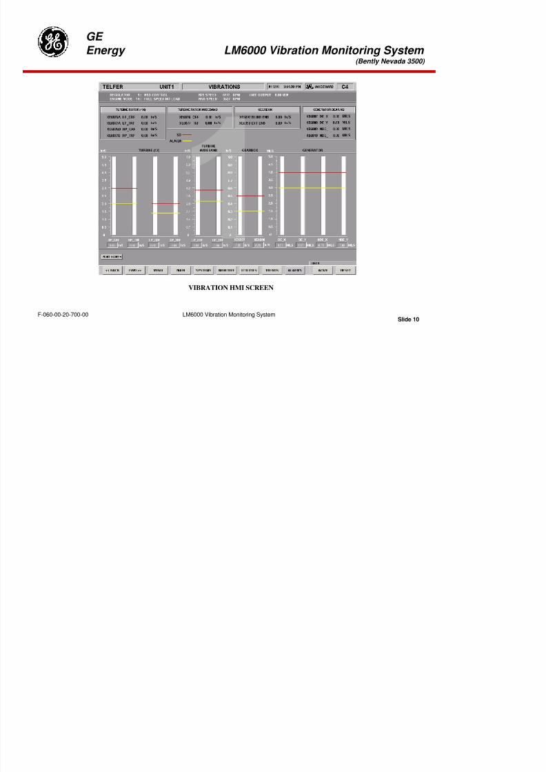
8/18/2019 71777896 - LM6000 Package Familiarization & Operations.pdf
http://slidepdf.com/reader/full/71777896-lm6000-package-familiarization-operationspdf 316/786
Slide 7LM6000 Vibration Monitoring SystemF-060-00-20-700-00
GE
Energy LM6000 Vibration Monitoring System (Bently Nevada 3500)
ACCELEROMETER

8/18/2019 71777896 - LM6000 Package Familiarization & Operations.pdf
http://slidepdf.com/reader/full/71777896-lm6000-package-familiarization-operationspdf 317/786
Slide 8LM6000 Vibration Monitoring SystemF-060-00-20-700-00
ACCELEROMETER OPERATION
GE
Energy LM6000 Vibration Monitoring System (Bently Nevada 3500)
Accelerometer Theory of Operation
In the study of physical systems, it is often desirable to observe the motion of a system and, in particular,
its acceleration.
An accelerometer can be described as a combination of the two transducers – the primary transducer,typically a single degree of freedom vibrating mass, or seismic mass, which converts the acceleration intodisplacement, and a secondary transducer which converts the displacement of the seismic mass into anelectric signal.
As the accelerometer reacts to motion, it places the piezoelectric crystal into compression or tension,which causes a surface charge to develop on the crystal. The charge is proportional to the displacementof the crystal. As the large body moves, the mass of the accelerometer will move with an inertialresponse. The piezoelectric crystal acts as the spring to provide a resisting force and damping. As theseismic mass moves, it places a piezoelectric crystal into compression or tension, which causes a surfacecharge to develop on the crystal, which is proportional to the motion.
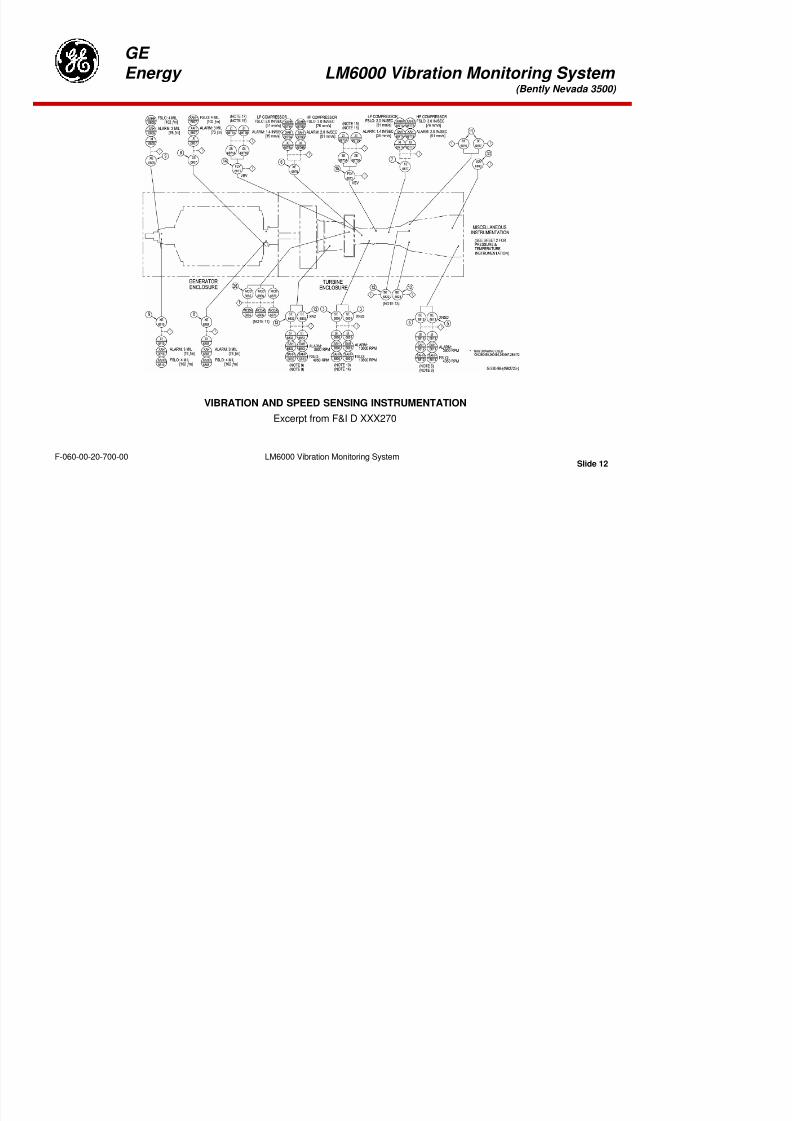
8/18/2019 71777896 - LM6000 Package Familiarization & Operations.pdf
http://slidepdf.com/reader/full/71777896-lm6000-package-familiarization-operationspdf 318/786
Slide 9LM6000 Vibration Monitoring SystemF-060-00-20-700-00
GE
Energy LM6000 Vibration Monitoring System (Bently Nevada 3500)

8/18/2019 71777896 - LM6000 Package Familiarization & Operations.pdf
http://slidepdf.com/reader/full/71777896-lm6000-package-familiarization-operationspdf 319/786
Slide 10LM6000 Vibration Monitoring SystemF-060-00-20-700-00
VIBRATION HMI SCREEN

8/18/2019 71777896 - LM6000 Package Familiarization & Operations.pdf
http://slidepdf.com/reader/full/71777896-lm6000-package-familiarization-operationspdf 320/786
GE
Energy LM6000 Vibration Monitoring System (Bently Nevada 3500)
VIBRATION AND SPEED SENSING INSTRUMENTATION
8/18/2019 71777896 - LM6000 Package Familiarization & Operations.pdf
http://slidepdf.com/reader/full/71777896-lm6000-package-familiarization-operationspdf 321/786
Slide 12LM6000 Vibration Monitoring SystemF-060-00-20-700-00
Excerpt from F&I D XXX270
GE
Energy LM6000 Vibration Monitoring System (Bently Nevada 3500)
BENTLEY 3500 RACK
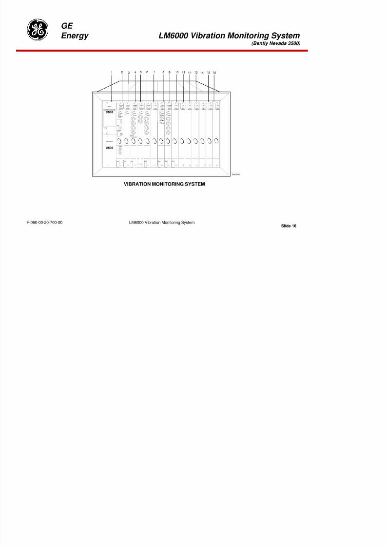
8/18/2019 71777896 - LM6000 Package Familiarization & Operations.pdf
http://slidepdf.com/reader/full/71777896-lm6000-package-familiarization-operationspdf 322/786
Slide 13LM6000 Vibration Monitoring SystemF-060-00-20-700-00
GE
Energy LM6000 Vibration Monitoring System (Bently Nevada 3500)
VIBRATION MONITORING SYSTEM
8/18/2019 71777896 - LM6000 Package Familiarization & Operations.pdf
http://slidepdf.com/reader/full/71777896-lm6000-package-familiarization-operationspdf 323/786
Slide 14LM6000 Vibration Monitoring SystemF-060-00-20-700-00
GE
Energy LM6000 Vibration Monitoring System (Bently Nevada 3500)
VIBRATION MONITORING SYSTEM
1. Low Voltage DC Power Supply / Future Expansion: Operates under fully loaded conditions with asingle power supply. When two power supplies are installed in a rack, the supply in the lower slotacts as the primary supply and the supply in the upper slot acts as the backup supply. If theprimary supply fails, the backup supply will provide power to the rack without interrupting rackoperation.
3. Communications Gateway Module: Provides serial communications between the 3500 MonitorSystem and a plant information system such as a distributed control system (DCS) or aprogrammable logic controller (PLC). Collects data from the modules in the rack over a high-speedinternal network and sends this data to the information system upon request. The module is ableto establish communications with up to six hosts over Ethernet.
2. Rack Interface Module: Primary interface that supports Bently-Nevada proprietary protocol used toconfigure the rack and retrieve machinery information. The rack interface module provides theconnections needed to support current Bently-Nevada Communications Processors and DynamicData Interface External.

8/18/2019 71777896 - LM6000 Package Familiarization & Operations.pdf
http://slidepdf.com/reader/full/71777896-lm6000-package-familiarization-operationspdf 324/786
Slide 15LM6000 Vibration Monitoring SystemF-060-00-20-700-00
GE
Energy LM6000 Vibration Monitoring System (Bently Nevada 3500)
VIBRATION MONITORING SYSTEM
8/18/2019 71777896 - LM6000 Package Familiarization & Operations.pdf
http://slidepdf.com/reader/full/71777896-lm6000-package-familiarization-operationspdf 325/786
Slide 16LM6000 Vibration Monitoring SystemF-060-00-20-700-00
GE
Energy LM6000 Vibration Monitoring System (Bently Nevada 3500)
4. Aero GT Vibration Monitor: 4-channel monitor that accepts input from four Velocity Transducersand uses these inputs to drive alarms. The monitor can be programmed using the 3500 Rack
Configuration Software to execute any filter options.
6. Proximitor Monitor: 4-channel module that accepts input from proximity transducers, linear variabledifferential transformers (DC & AC LVDTs), and rotary potentiometers and uses this input to drivealarms. It is programmed by using the 3500 Rack Configuration Software to perform any of thefollowing functions: Thrust Position, Differential Expansion, Ramp Differential Expansion,Complementary Input Differential Expansion, Case Expansion, and Valve Position.
5. Keyphasor Module: 2-channel module used to provide Keyphasor signals to the monitor modules.The module receives input signals from proximity probes or magnetic pickups and converts thesignals to digital Keyphasor signals that indicate when the Keyphasor mark on the shaft is under
the Keyphasor Probe. A Keyphasor signal is a digital timing signal that is used by monitor modulesand external diagnostic equipment to measure vector parameters like 1x amplitude and phase.
8/18/2019 71777896 - LM6000 Package Familiarization & Operations.pdf
http://slidepdf.com/reader/full/71777896-lm6000-package-familiarization-operationspdf 326/786
Slide 17LM6000 Vibration Monitoring SystemF-060-00-20-700-00
GE
Energy LM6000 Vibration Monitoring System (Bently Nevada 3500)
VIBRATION MONITORING SYSTEM

8/18/2019 71777896 - LM6000 Package Familiarization & Operations.pdf
http://slidepdf.com/reader/full/71777896-lm6000-package-familiarization-operationspdf 327/786
Slide 18LM6000 Vibration Monitoring SystemF-060-00-20-700-00
GE
Energy LM6000 Vibration Monitoring System (Bently Nevada 3500)
7. Future Expansion
8. 4 Channel Relay Module: Contains four relay outputs. Each relay output is fully programmableusing AND and OR voting. The Alarm Drive Logic for each relay channel can use alarming inputs(alerts and dangers) from any monitor channel in the rack. The Alarm Drive Logic is programmedusing the Rack Configuration Software.
9. Dynamic Pressure Monitor: Single slot, 4- channel monitor that accepts input from various hightemperature pressure transducers and uses this input to drive alarms. The monitor has one
proportional value per channel, bandpass dynamic pressure. The bandpass corner frequenciesare configured using the 3500 Rack Configuration Software along with an additional notch filter.
10. - 16. Future Expansion
8/18/2019 71777896 - LM6000 Package Familiarization & Operations.pdf
http://slidepdf.com/reader/full/71777896-lm6000-package-familiarization-operationspdf 328/786
Slide 19LM6000 Vibration Monitoring SystemF-060-00-20-700-00
GE
Energy LM6000 Vibration Monitoring System (Bently Nevada 3500)
Vibration Monitoring System Review
1. Engine vibration is measured using ___________________________. (What devices?)
2. Generator vibration is measured using ________________________. (What devices?)
3. Engine vibration monitoring is disabled at low HPT speeds to ____.
A. Prevent high-voltage excursions from the turbine-monitoring devices from damaging thesensitive vibration system electronics
B. Prevent annoying operators with nuisance alarms and possible shutdowns
C. Present only the most favorable vibration data to system operators
D. None of the above
4. Four velocity signal inputs are feed to the turbine frequency tracking filters to obtain data on theforward and aft frames of the engine at both HPT and LPT speeds.
A. True B. False

8/18/2019 71777896 - LM6000 Package Familiarization & Operations.pdf
http://slidepdf.com/reader/full/71777896-lm6000-package-familiarization-operationspdf 329/786
Slide 20LM6000 Vibration Monitoring SystemF-060-00-20-700-00
GE
Energy LM6000 Vibration Monitoring System (Bently Nevada 3500)
5. Proximitors mounted in the generator bearing housings measure ____.
A. Shaft displacement
B. Shaft deflection
C. Shaft x and y alignment
D. Changes in shaft speed
6. Tracking filters receive low-pressure (LPT) and high-pressure (HPT) velocity and speed signals.
A. True B. False
7. The vibration monitor display on the operator interface panel is calibrated in ____ per second forturbine vibration.
A. Inches per sec
B. Mills/millimeters per secC. Cubic feet per min
D. All of the above at operator discretion
8. Vibration monitoring of the engine is disabled until the HPT speed has increased aboverpm
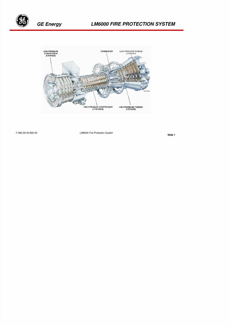
8/18/2019 71777896 - LM6000 Package Familiarization & Operations.pdf
http://slidepdf.com/reader/full/71777896-lm6000-package-familiarization-operationspdf 330/786
Slide 21LM6000 Vibration Monitoring SystemF-060-00-20-700-00
______________ rpm.
GE
Energy LM6000 Vibration Monitoring System (Bently Nevada 3500)
9.Vibration levels should not be changed by operators.
A. True B. False
10. Excessive generator rotor vibration requires pulling the main generator rotor and performing a closevisual examination of the bearings.
A. True B. False
11. The waveform of generator displacement is generally ____________.
A. Sinusoidal
B. Trapezoidal
C. Hexagonal
D. Tangential
12. Can the vibration data collected within the control system be graphed?

8/18/2019 71777896 - LM6000 Package Familiarization & Operations.pdf
http://slidepdf.com/reader/full/71777896-lm6000-package-familiarization-operationspdf 331/786
Slide 22LM6000 Vibration Monitoring SystemF-060-00-20-700-00
Tab 12
8/18/2019 71777896 - LM6000 Package Familiarization & Operations.pdf
http://slidepdf.com/reader/full/71777896-lm6000-package-familiarization-operationspdf 332/786
GE Energy LM6000 FIRE PROTECTION SYSTEM
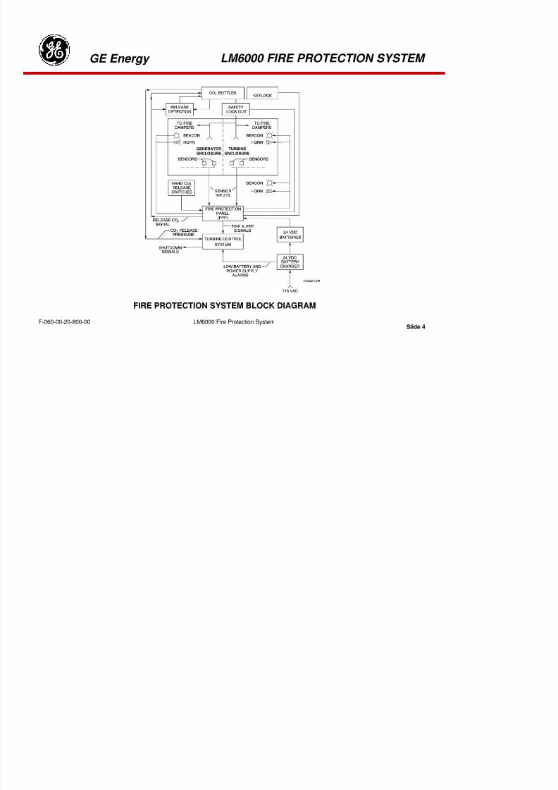
8/18/2019 71777896 - LM6000 Package Familiarization & Operations.pdf
http://slidepdf.com/reader/full/71777896-lm6000-package-familiarization-operationspdf 333/786
Slide 1LM6000 Fire Protection SystemF-060-00-20-800-00
GE Energy LM6000 FIRE PROTECTION SYSTEM

8/18/2019 71777896 - LM6000 Package Familiarization & Operations.pdf
http://slidepdf.com/reader/full/71777896-lm6000-package-familiarization-operationspdf 334/786
Slide 2LM6000 Fire Protection SystemF-060-00-20-800-00
GE Energy LM6000 FIRE PROTECTION SYSTEM
FIRE SYSTEM OPERATION
The fire protection system utilizes flame, thermal, and gas detectors in the generator and turbineenclosures to detect fire or fire-causing conditions. The system activates precautionary alarms or engineshutdown commands under specific conditions. Fire-extinguishing CO
2is released into the enclosures if
flames are detected or temperatures rise above set limits. Backup ventilation fans are activated toexhaust explosive gases from the enclosures should gas-air mixtures reach dangerous levels.
Pressure from CO2
in the release lines activates pneumatic actuators, pulling pins that allow weights to
fall, thus closing louvers (fire dampers) in the ventilation ducts. These fire dampers reduce the supply ofoxygen and confine CO
2within the enclosures for maximum effect.

8/18/2019 71777896 - LM6000 Package Familiarization & Operations.pdf
http://slidepdf.com/reader/full/71777896-lm6000-package-familiarization-operationspdf 335/786
Slide 3LM6000 Fire Protection SystemF-060-00-20-800-00
GE Energy LM6000 FIRE PROTECTION SYSTEM
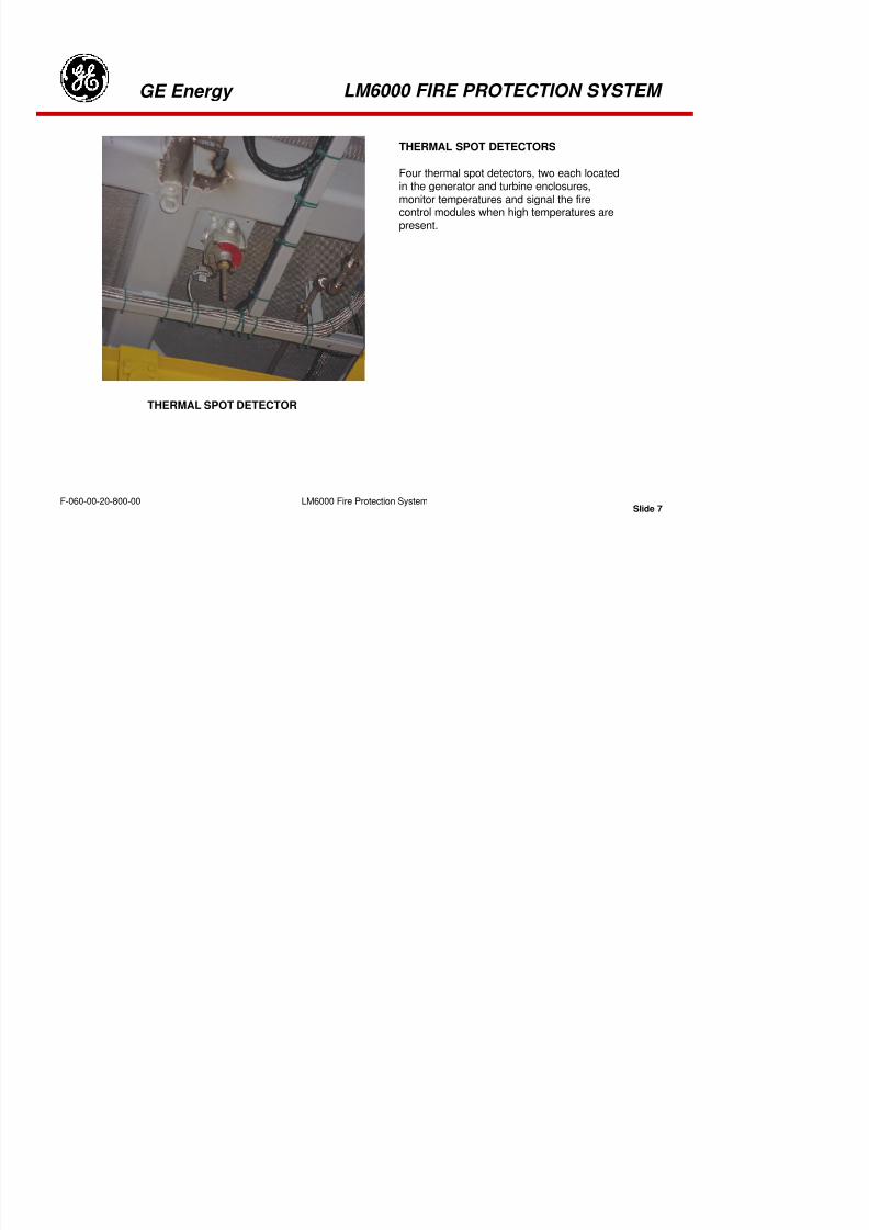
8/18/2019 71777896 - LM6000 Package Familiarization & Operations.pdf
http://slidepdf.com/reader/full/71777896-lm6000-package-familiarization-operationspdf 336/786
Slide 4LM6000 Fire Protection SystemF-060-00-20-800-00
FIRE PROTECTION SYSTEM BLOCK DIAGRAM
GE Energy LM6000 FIRE PROTECTION SYSTEM
THEORY OF OPERATION
Because of its importance to the system while running, and in Standby or Static state, the Allestec Fire
Protection system performs a routine “system check” every 36 hours. At time of initial power-up, the FPPsets an internal watchdog timer that initiates a status check at 36-hour intervals. During this period thesystem looks at each circuit run to the manual switches, heat sensors, flame detectors, gas detectors,pressure switches and battery charger system to verify proper operating parameters of the externalcomponents. If a device is not functioning properly, or if the system detects a loss of circuit continuity, analarm will be annunciated and displayed on the Operator’s Alarm and Shutdown screen on the HMI.

8/18/2019 71777896 - LM6000 Package Familiarization & Operations.pdf
http://slidepdf.com/reader/full/71777896-lm6000-package-familiarization-operationspdf 337/786
Slide 5LM6000 Fire Protection SystemF-060-00-20-800-00
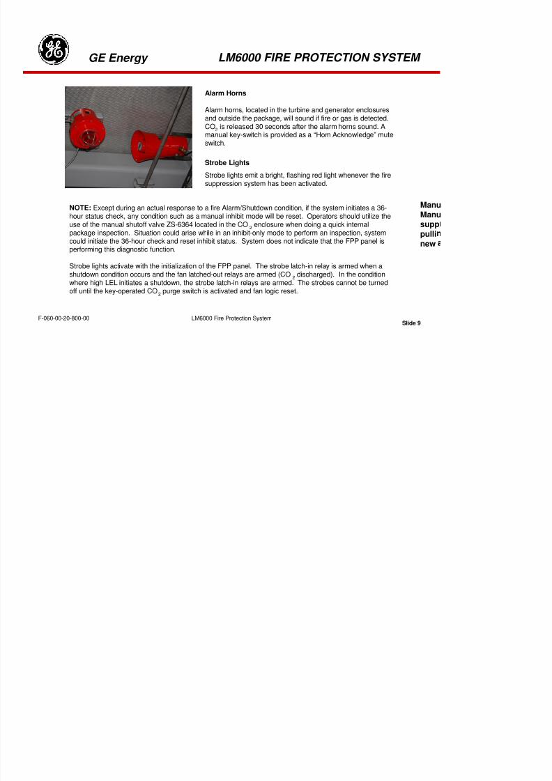
8/18/2019 71777896 - LM6000 Package Familiarization & Operations.pdf
http://slidepdf.com/reader/full/71777896-lm6000-package-familiarization-operationspdf 338/786
GE Energy LM6000 FIRE PROTECTION SYSTEM
THERMAL SPOT DETECTORS
Four thermal spot detectors, two each locatedin the generator and turbine enclosures,monitor temperatures and signal the firecontrol modules when high temperatures arepresent.
THERMAL SPOT DETECTOR
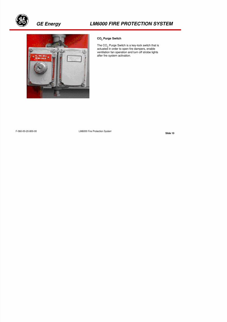
8/18/2019 71777896 - LM6000 Package Familiarization & Operations.pdf
http://slidepdf.com/reader/full/71777896-lm6000-package-familiarization-operationspdf 339/786
Slide 7LM6000 Fire Protection SystemF-060-00-20-800-00
GE Energy LM6000 FIRE PROTECTION SYSTEM
COMBUSTIBLE GAS DETECTOR
COMBUSTIBLE GAS DETECTORS
Combustible gas is detected by three dual-
element sensors, two for the turbineenclosure and one for the generatorenclosure. The dual elements, one ofwhich is exposed to the local atmosphereand one of which is sealed, are balanced tocancel the effects of temperature, aging,and humidity. An unbalance occurs whengas affects the electrical conductivity of theexposed element.
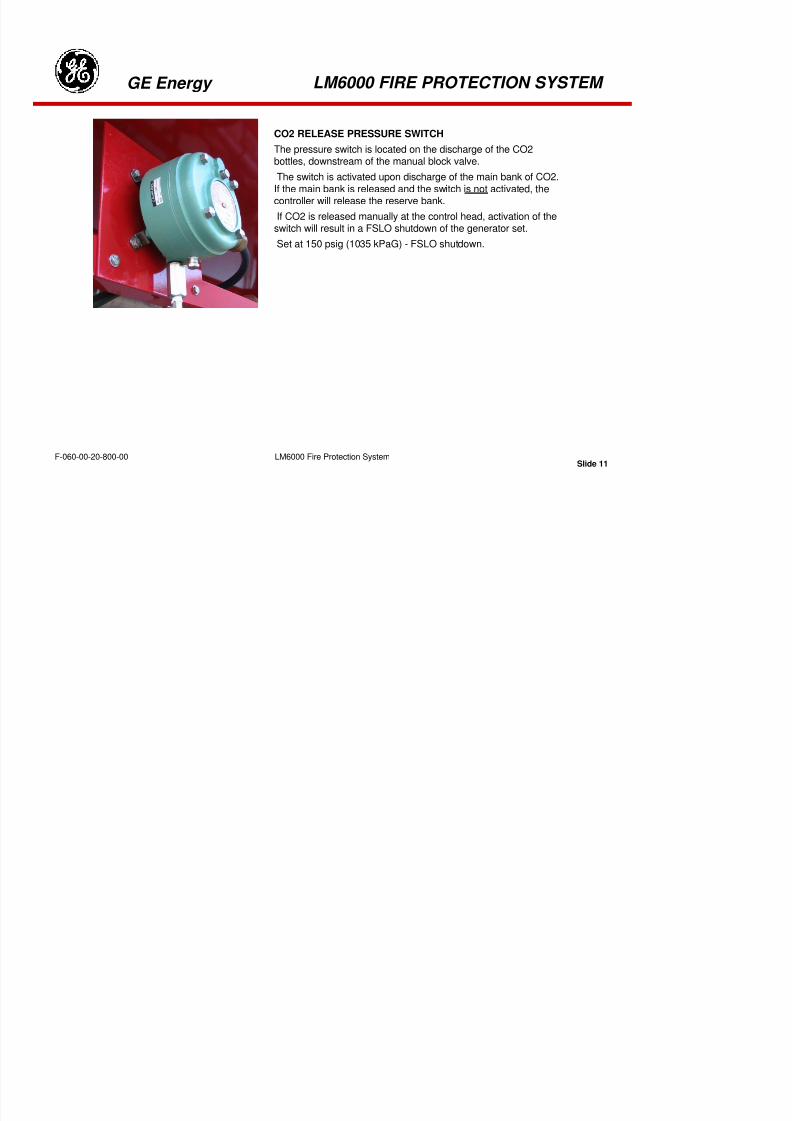
8/18/2019 71777896 - LM6000 Package Familiarization & Operations.pdf
http://slidepdf.com/reader/full/71777896-lm6000-package-familiarization-operationspdf 340/786
Slide 8LM6000 Fire Protection SystemF-060-00-20-800-00
GE Energy LM6000 FIRE PROTECTION SYSTEM
Alarm Horns
Alarm horns, located in the turbine and generator enclosuresand outside the package, will sound if fire or gas is detected.CO
2is released 30 seconds after the alarm horns sound. A
manual key-switch is provided as a “Horn Acknowledge” muteswitch.
Manu
Manusupp
pulli
new
Strobe Lights
Strobe lights emit a bright, flashing red light whenever the firesuppression system has been activated.
NOTE: Except during an actual response to a fire Alarm/Shutdown condition, if the system initiates a 36-hour status check, any condition such as a manual inhibit mode will be reset. Operators should utilize theuse of the manual shutoff valve ZS-6364 located in the CO
2enclosure when doing a quick internal
package inspection. Situation could arise while in an inhibit-only mode to perform an inspection, system
could initiate the 36-hour check and reset inhibit status. System does not indicate that the FPP panel isperforming this diagnostic function.
Strobe lights activate with the initialization of the FPP panel. The strobe latch-in relay is armed when ashutdown condition occurs and the fan latched-out relays are armed (CO
2discharged). In the condition
where high LEL initiates a shutdown, the strobe latch-in relays are armed. The strobes cannot be turnedoff until the key-operated CO
2purge switch is activated and fan logic reset.

8/18/2019 71777896 - LM6000 Package Familiarization & Operations.pdf
http://slidepdf.com/reader/full/71777896-lm6000-package-familiarization-operationspdf 341/786
Slide 9LM6000 Fire Protection SystemF-060-00-20-800-00
GE Energy LM6000 FIRE PROTECTION SYSTEM
CO2
Purge Switch
The CO2
Purge Switch is a key-lock switch that isactuated in order to open fire dampers, enableventilation fan operation and turn off strobe lightsafter fire system activation.

8/18/2019 71777896 - LM6000 Package Familiarization & Operations.pdf
http://slidepdf.com/reader/full/71777896-lm6000-package-familiarization-operationspdf 342/786
Slide 10LM6000 Fire Protection SystemF-060-00-20-800-00
GE Energy LM6000 FIRE PROTECTION SYSTEM
CO2 RELEASE PRESSURE SWITCH
The pressure switch is located on the discharge of the CO2
bottles, downstream of the manual block valve.The switch is activated upon discharge of the main bank of CO2.
If the main bank is released and the switch is not activated, thecontroller will release the reserve bank.
If CO2 is released manually at the control head, activation of theswitch will result in a FSLO shutdown of the generator set.
Set at 150 psig (1035 kPaG) - FSLO shutdown.

8/18/2019 71777896 - LM6000 Package Familiarization & Operations.pdf
http://slidepdf.com/reader/full/71777896-lm6000-package-familiarization-operationspdf 343/786
Slide 11LM6000 Fire Protection SystemF-060-00-20-800-00
GE Energy LM6000 FIRE PROTECTION SYSTEM
CO2 BOTTLE RELEASE SOLENOID VALVE(CONTROL HEAD)
Two solenoid operated release valves are mounted
in each of the banks of bottles (Main and Reserve).It only takes one per bank to actuate the CO2system.
CO2 system may be manually actuated for thesolenoid valve. Resetting the valve is completedmanually with a screw driver.
CO2 MANUAL BLOCK VALVE
Manual operated valve located on thedischarge side of the CO2 bottles. Utilizedwhen accessing the enclosures to ensure noaccidentally CO2 release in the module.
The valve has an electronic position feedbackto the fire protection panel. In the closedposition, release of CO2 is inhibited.

8/18/2019 71777896 - LM6000 Package Familiarization & Operations.pdf
http://slidepdf.com/reader/full/71777896-lm6000-package-familiarization-operationspdf 344/786
Slide 12LM6000 Fire Protection SystemF-060-00-20-800-00
GE Energy LM6000 FIRE PROTECTION SYSTEM
Gas Turbine Enclosure Ventilation Fan FireDampers (2)
Each gas turbine ventilation fan has a firedamper on the inlet side of the fan. During a“Fire Stop” the fire dampers are closed by CO
2
pressure to stop all airflow from the enclosure.Compressed air is used to reset fire dampers.
FIRE DAMPER ACTUATORS
Located outside the turbine enclosure is aninstrument air fitting that is used for resetting firedampers. Under normal operation the supply airvalve is closed and the discharge valve is open,vented to atmosphere. To reset dampers, close thedischarge valve and open the air supply to dampers.After reset, close the air supply valve and open the
discharge valve to atmosphere.

8/18/2019 71777896 - LM6000 Package Familiarization & Operations.pdf
http://slidepdf.com/reader/full/71777896-lm6000-package-familiarization-operationspdf 345/786
Slide 13LM6000 Fire Protection SystemF-060-00-20-800-00
discharge valve to atmosphere.
GE Energy LM6000 FIRE PROTECTION SYSTEM
FIRE PROTECTION PANEL
The Fire Protection Panel illustrated above is comprised of plug-in modules that link to flame, thermal, and
gas detection sensors inside the turbine and generator enclosures. The FPP also contains Alarm,Release, Manual Pull, and Fault modules that provide activation of CO2
release solenoids andannunciation of operating conditions. The function of the individual modules is as described on thefollowing pages.

8/18/2019 71777896 - LM6000 Package Familiarization & Operations.pdf
http://slidepdf.com/reader/full/71777896-lm6000-package-familiarization-operationspdf 346/786
Slide 14LM6000 Fire Protection SystemF-060-00-20-800-00
GE Energy LM6000 FIRE PROTECTION SYSTEM
NOTE: Unlike most modular control systems, the “slots” within the Fire Protection System cardframe arenumbered from right to left. Thus, for reference, the module in slot number 1 is located at the far right
hand end of the cardframe, when viewed from the front of the control panel.

8/18/2019 71777896 - LM6000 Package Familiarization & Operations.pdf
http://slidepdf.com/reader/full/71777896-lm6000-package-familiarization-operationspdf 347/786
Slide 15LM6000 Fire Protection SystemF-060-00-20-800-00
GE Energy LM6000 FIRE PROTECTION SYSTEM
FAULT MODULEThe Fault module assists operators in identifying fault categories
and provides a mechanism for resetting the audible fault horn. ThePower LED indicates low battery supply voltage. The AUX LED isnot used in the system as presently configured. Faults are alsodisplayed locally on each plug-in module type.
1. System – Amber indicator illuminates when a fault in anymodule in the system is present.
2. Battery Voltage – Green indicator illuminates should the batterypower rise to approximately 30V or fall to approximately 18V.
3. Aux – (Not Used) Amber indicator illuminates when normally closed circuitis open.
4. Power LED – Green indicator illuminates when power is applied to themodule.
5. Reset Switch – Toggle switch used to reset module and alarm conditions.

8/18/2019 71777896 - LM6000 Package Familiarization & Operations.pdf
http://slidepdf.com/reader/full/71777896-lm6000-package-familiarization-operationspdf 348/786
Slide 16LM6000 Fire Protection SystemF-060-00-20-800-00
GE Energy LM6000 FIRE PROTECTION SYSTEM
MANUAL PULL MODULE
The Manual Pull module accepts inputs from manual pull switcheslocated strategically around the GTG package and sets a latch, whichactivates the Alarm and Release modules. Operation of any of themanual pull switches also causes the Fire LED on the module frontpanel to energize.
1. Fire – Upon activation of a manual pull station, this LEDwill illuminate and audio and visual alarms will be activated.The release module will also be activated.
2. Fault – Amber indicator will illuminate when a circuitis open in the manual release input wiring and the alarm
will be activated.
3. Power LED – Green indicator illuminates when power is appliedto the module.
4. Inhibit/Reset – Toggle switch allows testing of the detectors whiledisabling the main and reserve banks of the release module.

8/18/2019 71777896 - LM6000 Package Familiarization & Operations.pdf
http://slidepdf.com/reader/full/71777896-lm6000-package-familiarization-operationspdf 349/786
Slide 17LM6000 Fire Protection SystemF-060-00-20-800-00
GE Energy LM6000 FIRE PROTECTION SYSTEM
RELEASE MODULE
The release module activates CO2
release solenoids after pre-set time
delays. Manual pull switches, high temperature detection, or flamedetection will activate a 30-second timer in the Release module. Followingthe 30-second warning delay, the primary bank of CO
2bottles is released.
At the time of release, 10-second and 90-second timers are initiated. If CO2
pressure is not sensed in the release lines when the 10-second timerelapses, the backup bottle bank is released. If flames continue to bedetected when the 90-second timer elapses, the backup bottle bank is also
released.
1. Main – Red indicator illuminates when CO2is released from CO
2
cylinders.
2. Reserve – Red indicator illuminates when CO2is released from reserve
CO2cylinders.
3. Main – Amber indicator illuminates when an open conductor in the MainRelease circuit is detected.

8/18/2019 71777896 - LM6000 Package Familiarization & Operations.pdf
http://slidepdf.com/reader/full/71777896-lm6000-package-familiarization-operationspdf 350/786
Slide 18LM6000 Fire Protection SystemF-060-00-20-800-00
GE Energy LM6000 FIRE PROTECTION SYSTEM
4. Reserve – Amber indicator illuminates when an open conductor in the Reserve Release circuit isdetected.
5. PSW – Amber indicator illuminates when an open conductor inthe Pressure Switch (PSW) line is detected.
6. Abort – Amber indicator will illuminate when an open conductor in the abort line is detected.
7. Power LED – Green indicator illuminates when power is applied to the module.
8. Inhibit/Reset Switch – Inhibit position inhibits release of CO2
while testing Input Module Alarms.Manual Pulls may still be used in normal manner while Inhibit function is selected. Reset position allowsuser to reset the fault circuit provided the condition causing the fault has been cleared.

8/18/2019 71777896 - LM6000 Package Familiarization & Operations.pdf
http://slidepdf.com/reader/full/71777896-lm6000-package-familiarization-operationspdf 351/786
Slide 19LM6000 Fire Protection SystemF-060-00-20-800-00
GE Energy LM6000 FIRE PROTECTION SYSTEM
INPUT MODULE (TURBINE OPTICS)
The input module for the turbine optics accepts inputs from the three optical
flame detectors in the turbine enclosure. Once activated by a detector the InputModule will initiate the Alarm Module and the Release Module. When reset withthe spring-loaded Reset switch, the LEDs extinguish. Fault LEDs do not blink.To prevent nuisance alarms, adjustable time delays on the input module printedcircuit cards determine the length of time sensor contacts must remain closedbefore being “captured” and presented as a valid signal.
1. Fire 1 – Red indicator illuminates as long as the detector remains in alarm.
When the alarm clears, the LED will blink to indicate there has been a relayclosure. The module can be reset when all alarms on this module have beencleared.
2. Fire 2 – Red indicator illuminates as long as the detector remains in alarm.When the alarm clears, the LED will blink to indicate there has been a relayclosure. The module can be reset when all alarms on this module have beencleared.
3. Fire 3 – Red indicator illuminates as long as the detector remains in alarm.When the alarm clears, the LED will blink to indicate there has been a relayclosure. The module can be reset when all alarms on this module have beencleared
4. Fault 1 – Amber indicator illuminates when there is a sensor contact open inNo. 1 Fault Input circuit.

8/18/2019 71777896 - LM6000 Package Familiarization & Operations.pdf
http://slidepdf.com/reader/full/71777896-lm6000-package-familiarization-operationspdf 352/786
Slide 20LM6000 Fire Protection SystemF-060-00-20-800-00
GE Energy LM6000 FIRE PROTECTION SYSTEM
5. Fault 2 – Amber indicator illuminates when there is a sensor contact open in No. 2 Fault Input circuit.
6. Fault 3 – Amber indicator illuminates when there is a sensor contact open in No. 3 Fault Input circuit.
7. Power LED – Green indicator illuminates when power is applied to the module.
8. Reset Switch – Allows resetting the input module.
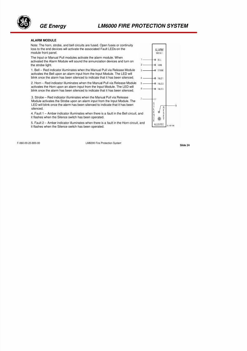
8/18/2019 71777896 - LM6000 Package Familiarization & Operations.pdf
http://slidepdf.com/reader/full/71777896-lm6000-package-familiarization-operationspdf 353/786
Slide 21LM6000 Fire Protection SystemF-060-00-20-800-00
GE Energy LM6000 FIRE PROTECTION SYSTEM
INPUT MODULE (GENERATOR OPTICS)
The input module for the generator optics accepts inputs from thesingle optical flame detector in the generator enclosure and four
thermal sensor inputs. Two thermal inputs are wired in parallel fromthe turbine enclosure and two from the generator enclosure. Onceactivated by a detector the Input Module will initiate the Alarm Moduleand the Release Module. When reset with the spring-loaded Resetswitch, the LEDs extinguish. Fault LEDs do not blink.
To prevent nuisance alarms, adjustable time delays on the input moduleprinted circuit cards determine the length of time sensor contacts must
remain closed before being “captured” and presented as a valid signal.1. Fire 1 – Red indicator illuminates as long as the detector remains inalarm. When the alarm clears, the LED will blink to indicate there hasbeen a relay closure. The module can be reset when all alarms on thismodule have been cleared.
2. Fire 2 – Red indicator illuminates as long as the detector remains inalarm. When the alarm clears, the LED will blink to indicate there has been
a relay closure. The module can be reset when all alarms on this modulehave been cleared.
3. Fire 3 – Red indicator illuminates as long as the detector remains in alarm.When the alarm clears, the LED will blink to indicate there has been a relayclosure. The module can be reset when all alarms on this module have beencleared

8/18/2019 71777896 - LM6000 Package Familiarization & Operations.pdf
http://slidepdf.com/reader/full/71777896-lm6000-package-familiarization-operationspdf 354/786
Slide 22LM6000 Fire Protection SystemF-060-00-20-800-00
GE Energy
LM6000 Fi P t ti S t
LM6000 FIRE PROTECTION SYSTEM
F 060 00 20 800 00
4. Fault 1 – Amber indicator illuminates when there is a sensor contact open in No. 1 Fault Input circuit.
5. Fault 2 – Amber indicator illuminates when there is a sensor contact open in No. 2 Fault Input circuit.
6. Fault 3 – Amber indicator illuminates when there is a sensor contact open in No. 3 Fault Input circuit.
7. Power LED – Green indicator illuminates when power is applied to the module.
8. Reset Switch – Allows resetting the input module.

8/18/2019 71777896 - LM6000 Package Familiarization & Operations.pdf
http://slidepdf.com/reader/full/71777896-lm6000-package-familiarization-operationspdf 355/786
Slide 23LM6000 Fire Protection SystemF-060-00-20-800-00
GE Energy
LM6000 Fire Protection System
LM6000 FIRE PROTECTION SYSTEM
F 060 00 20 800 00
ALARM MODULE
Note: The horn, strobe, and bell circuits are fused. Open fuses or continuityloss to the end devices will activate the associated Fault LEDs on the
module front panel.The Input or Manual Pull modules activate the alarm module. Whenactivated the Alarm Module will sound the annunciation devices and turn onthe strobe light.
1. Bell – Red indicator illuminates when the Manual Pull via Release Moduleactivates the Bell upon an alarm input from the Input Module. The LED willblink once the alarm has been silenced to indicate that it has been silenced.
2. Horn – Red indicator illuminates when the Manual Pull via Release Moduleactivates the Horn upon an alarm input from the Input Module. The LED willblink once the alarm has been silenced to indicate that it has been silenced.
3. Strobe – Red indicator illuminates when the Manual Pull via ReleaseModule activates the Strobe upon an alarm input from the Input Module. TheLED will blink once the alarm has been silenced to indicate that it has been
silenced.4. Fault 1 – Amber indicator illuminates when there is a fault in the Bell circuit, andit flashes when the Silence switch has been operated.
5. Fault 2 – Amber indicator illuminates when there is a fault in the Horn circuit, andit flashes when the Silence switch has been operated.
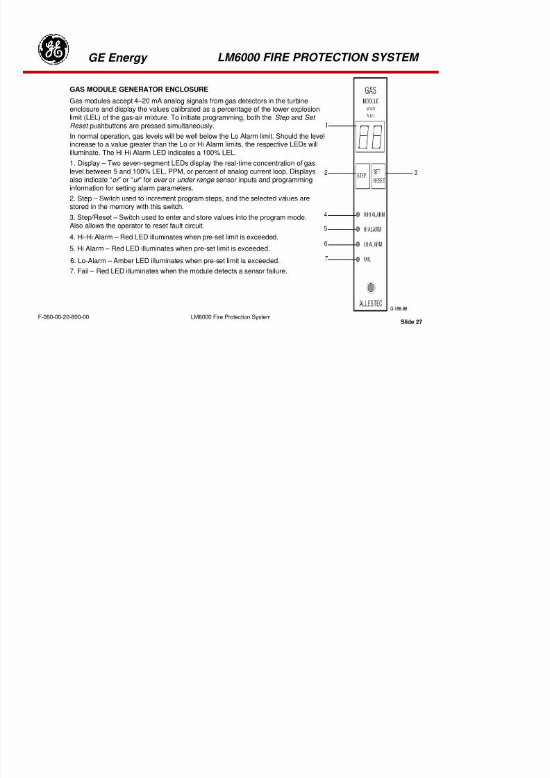
8/18/2019 71777896 - LM6000 Package Familiarization & Operations.pdf
http://slidepdf.com/reader/full/71777896-lm6000-package-familiarization-operationspdf 356/786
Slide 24LM6000 Fire Protection SystemF-060-00-20-800-00
GE Energy
LM6000 Fire Protection System
LM6000 FIRE PROTECTION SYSTEM
F 060 00 20 800 00
6. Fault 3 – Amber indicator when there is a fault in the strobe light circuit.
7. Power LED – Green indicator illuminates when power is applied to the module.
8. Silence/Reset Switch – The Silence function will silence the horn after whichthe Horn LED blinks until Reset is activated. The reset function extinguishes theHorn and Strobe LEDs. The Reset function is only permitted if the event causingthe alarm is cleared.
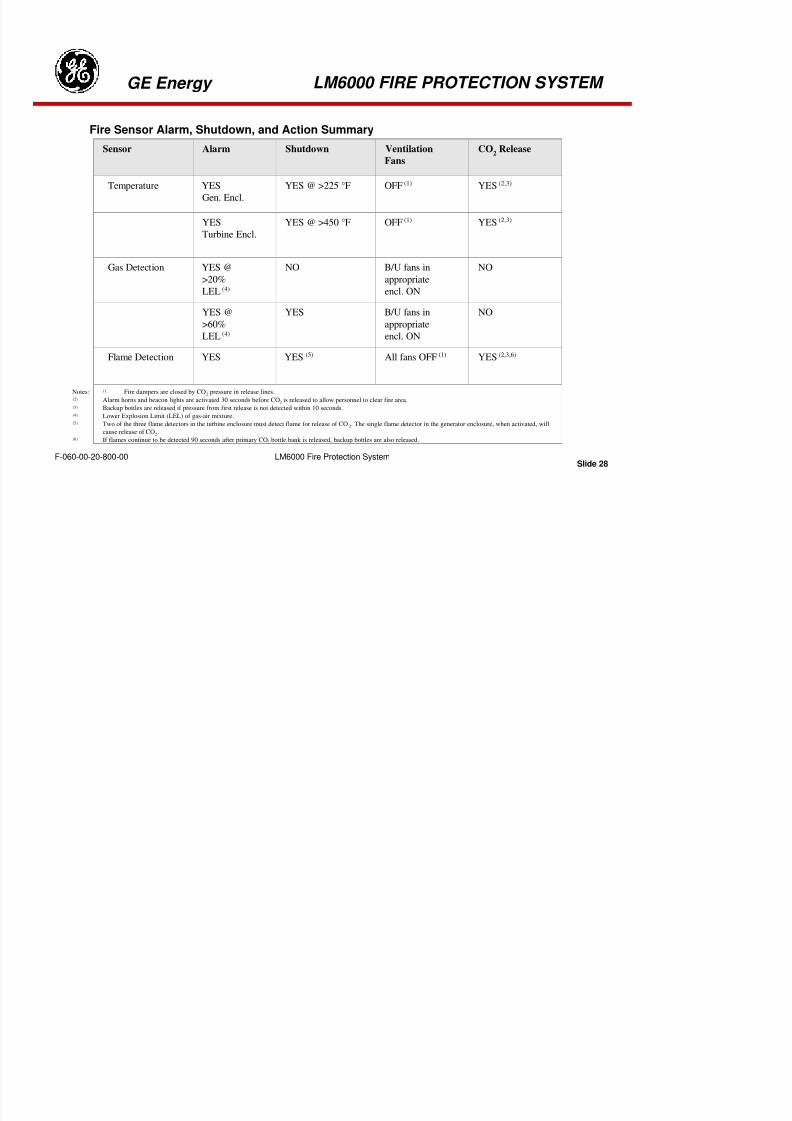
8/18/2019 71777896 - LM6000 Package Familiarization & Operations.pdf
http://slidepdf.com/reader/full/71777896-lm6000-package-familiarization-operationspdf 357/786
Slide 25LM6000 Fire Protection SystemF-060-00-20-800-00
GE Energy
LM6000 Fire Protection System
LM6000 FIRE PROTECTION SYSTEM
F-060-00-20-800-00
GAS MODULE TURBINE ENCLOSURE
Gas modules accept 4–20 mA analog signals from gas detectors in the turbine
enclosure and display the values calibrated as a percentage of the lowerexplosion limit (LEL) of the gas-air mixture. To initiate programming, both the Step
and Set Reset pushbuttons are pressed simultaneously.
In normal operation, gas levels will be well below the Lo Alarm limit. Should thelevel increase to a value greater than the Lo or Hi Alarm limits, the respectiveLEDs will illuminate. The HiHi Alarm LED indicates a 100% LEL.
1. Display – Two seven-segment LEDs display the real-time concentration of
gas level between 5 and 100% LEL, PPM, or percent of analog current loop.Displays also indicate “or ” or “ur ” for over or under range sensor inputs andprogramming information for setting alarm parameters.
2. Step – Switch used to increment program steps, and the selected valuesare stored in the memory with this switch.
3. Step/Reset – Switch used to enter and store values into the program mode.Also allows the operator to reset fault circuit.
4. Hi-Hi Alarm – Red LED illuminates when pre-set limit is exceeded.
5. Hi Alarm – Red LED illuminates when pre-set limit is exceeded.
6. Lo-Alarm – Amber LED illuminates when pre-set limit is exceeded.
7. Fail – Red LED illuminates when the module detects a sensor failure.
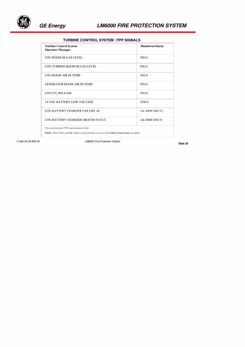
8/18/2019 71777896 - LM6000 Package Familiarization & Operations.pdf
http://slidepdf.com/reader/full/71777896-lm6000-package-familiarization-operationspdf 358/786
Slide 26LM6000 Fire Protection SystemF 060 00 20 800 00
GE Energy
LM6000 Fire Protection System
LM6000 FIRE PROTECTION SYSTEM
F-060-00-20-800-00
GAS MODULE GENERATOR ENCLOSURE
Gas modules accept 4–20 mA analog signals from gas detectors in the turbineenclosure and display the values calibrated as a percentage of the lower explosion
limit (LEL) of the gas-air mixture. To initiate programming, both the Step and SetReset pushbuttons are pressed simultaneously.
In normal operation, gas levels will be well below the Lo Alarm limit. Should the levelincrease to a value greater than the Lo or Hi Alarm limits, the respective LEDs willilluminate. The Hi Hi Alarm LED indicates a 100% LEL.
1. Display – Two seven-segment LEDs display the real-time concentration of gaslevel between 5 and 100% LEL, PPM, or percent of analog current loop. Displays
also indicate “or ” or “ur ” for over or under range sensor inputs and programminginformation for setting alarm parameters.
2. Step – Switch used to increment program steps, and the selected values arestored in the memory with this switch.
3. Step/Reset – Switch used to enter and store values into the program mode.Also allows the operator to reset fault circuit.
4. Hi-Hi Alarm – Red LED illuminates when pre-set limit is exceeded.
5. Hi Alarm – Red LED illuminates when pre-set limit is exceeded.
6. Lo-Alarm – Amber LED illuminates when pre-set limit is exceeded.
7. Fail – Red LED illuminates when the module detects a sensor failure.
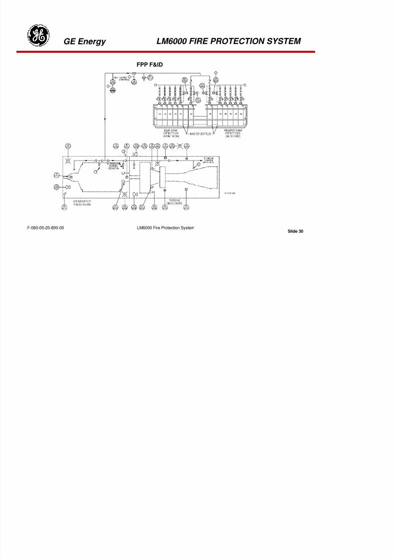
8/18/2019 71777896 - LM6000 Package Familiarization & Operations.pdf
http://slidepdf.com/reader/full/71777896-lm6000-package-familiarization-operationspdf 359/786
Slide 27LM6000 Fire Protection SystemF 060 00 20 800 00
Slid 28
GE Energy
LM6000 Fire Protection System
LM6000 FIRE PROTECTION SYSTEM
F-060-00-20-800-00
Fire Sensor Alarm, Shutdown, and Action Summary
Sensor Alarm Shutdown Ventilation
Fans
CO2 Release
Temperature YES
Gen. Encl.
YES @ >225 °F OFF (1) YES (2,3)
YES
Turbine Encl.
YES @ >450 °F OFF (1) YES (2,3)
Gas Detection YES @
>20%
LEL (4)
NO B/U fans in
appropriate
encl. ON
NO
YES @
>60%
LEL (4)
YES B/U fans in
appropriate
encl. ON
NO
Flame Detection YES YES (5) All fans OFF (1) YES (2,3,6)
Notes: (1) Fire dampers are closed by CO2 pressure in release lines.(2) Alarm horns and beacon lights are activated 30 seconds before CO2 is released to allow personnel to clear fire area.(3) Backup bottles are released if pressure from first release is not detected within 10 seconds.(4) Lower Explosion Limit (LEL) of gas-air mixture.(5) Two of the three flame detectors in the turbine enclosure must detect flame for release of CO 2. The single flame detector in the generator enclosure, when activated, will
cause release of CO2.(6) If flames continue to be detected 90 seconds after primary CO2 bottle bank is released, backup bottles are also released.
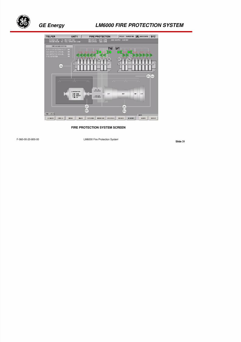
8/18/2019 71777896 - LM6000 Package Familiarization & Operations.pdf
http://slidepdf.com/reader/full/71777896-lm6000-package-familiarization-operationspdf 360/786
Slide 28y
Slid 29
GE Energy
LM6000 Fire Protection System
LM6000 FIRE PROTECTION SYSTEM
F-060-00-20-800-00
TURBINE CONTROL SYSTEM \ FPP SIGNALS
Turbine Control System
Operator Messages
Shutdown/Alarm
GTG ROOM HI GAS LEVEL FSLO
GTG TURBINE ROOM HI GAS LEVEL FSLO
GTG ROOM AIR HI TEMP FSLO
GENERATOR ROOM AIR HI TEMP FSLO
GTG CO2
RELEASE FSLO
24-VDC BATTERY LOW VOLTAGE CDLO
GTG BATTERY CHARGER FAILURE AC (ALARM ONLY)
GTG BATTERY CHARGER GROUND FAULT (ALARM ONLY)
*Fire protection panel (FPP) internal diagnostic fault.
NOTE: FSLO, CDLO, and SML shutdown mode definitions are given in the Turbine Control System description.
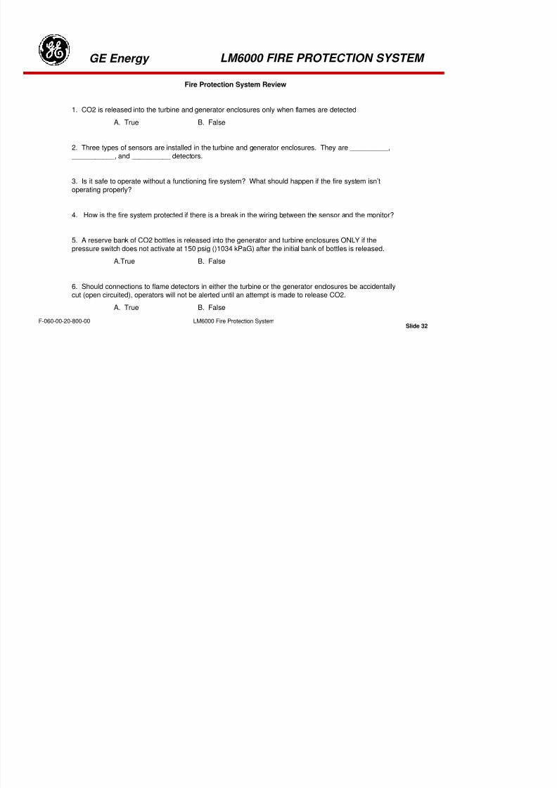
8/18/2019 71777896 - LM6000 Package Familiarization & Operations.pdf
http://slidepdf.com/reader/full/71777896-lm6000-package-familiarization-operationspdf 361/786
Slide 29
Slide 30
GE Energy
LM6000 Fire Protection System
LM6000 FIRE PROTECTION SYSTEM
F-060-00-20-800-00
FPP F&ID

8/18/2019 71777896 - LM6000 Package Familiarization & Operations.pdf
http://slidepdf.com/reader/full/71777896-lm6000-package-familiarization-operationspdf 362/786
Slide 30
Slide 31
GE Energy
LM6000 Fire Protection System
LM6000 FIRE PROTECTION SYSTEM
F-060-00-20-800-00
FIRE PROTECTION SYSTEM SCREEN

8/18/2019 71777896 - LM6000 Package Familiarization & Operations.pdf
http://slidepdf.com/reader/full/71777896-lm6000-package-familiarization-operationspdf 363/786
Slide 31
Slide 32
GE Energy
LM6000 Fire Protection System
LM6000 FIRE PROTECTION SYSTEM
F-060-00-20-800-00
Fire Protection System Review
1. CO2 is released into the turbine and generator enclosures only when flames are detected
A. True B. False
2. Three types of sensors are installed in the turbine and generator enclosures. They are __________, ___________, and __________ detectors.
3. Is it safe to operate without a functioning fire system? What should happen if the fire system isn’toperating properly?
4. How is the fire system protected if there is a break in the wiring between the sensor and the monitor?
5. A reserve bank of CO2 bottles is released into the generator and turbine enclosures ONLY if thepressure switch does not activate at 150 psig ()1034 kPaG) after the initial bank of bottles is released.
A.True B. False
6. Should connections to flame detectors in either the turbine or the generator enclosures be accidentallycut (open circuited), operators will not be alerted until an attempt is made to release CO2.
A. True B. False

8/18/2019 71777896 - LM6000 Package Familiarization & Operations.pdf
http://slidepdf.com/reader/full/71777896-lm6000-package-familiarization-operationspdf 364/786
Slide 32
Tab 13

8/18/2019 71777896 - LM6000 Package Familiarization & Operations.pdf
http://slidepdf.com/reader/full/71777896-lm6000-package-familiarization-operationspdf 365/786
Electrical Systems
gGE Energy Electrical Systems
Slide 1F-000-00-60-000-00
ELECTRICAL SYSTEMS

8/18/2019 71777896 - LM6000 Package Familiarization & Operations.pdf
http://slidepdf.com/reader/full/71777896-lm6000-package-familiarization-operationspdf 366/786
8/18/2019 71777896 - LM6000 Package Familiarization & Operations.pdf
http://slidepdf.com/reader/full/71777896-lm6000-package-familiarization-operationspdf 367/786
Electrical Systems
gGE Energy Electrical Systems
Slide 3F-000-00-60-000-00
Field Around A Current-Carrying Conductor

8/18/2019 71777896 - LM6000 Package Familiarization & Operations.pdf
http://slidepdf.com/reader/full/71777896-lm6000-package-familiarization-operationspdf 368/786
Electrical Systems
gGE Energy Electrical Systems
Slide 4F-000-00-60-000-00
Right Hand Rule
Predicting the direction of the magnetic field, or of the direction of current flow, using can beaccomplished using the right-hand rule. When pointing the right-hand thumb in the direction ofcurrent flow, the fingers will curl in the direction of magnetic flux. And, of course, if the fingers ofthe right-hand are curled in the direction of the magnetic flux, the thumb will point in the directionof current flow.
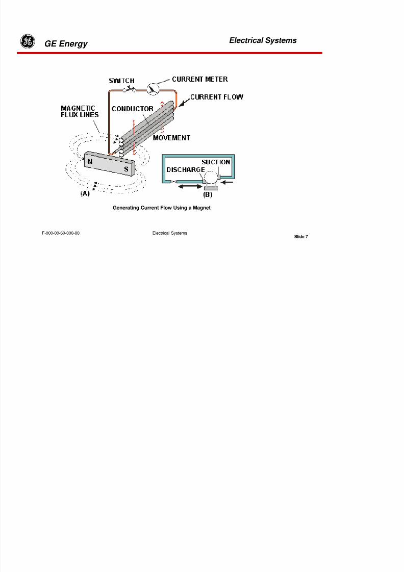
8/18/2019 71777896 - LM6000 Package Familiarization & Operations.pdf
http://slidepdf.com/reader/full/71777896-lm6000-package-familiarization-operationspdf 369/786
Electrical Systems
gGE Energy Electrical Systems
Slide 5F-000-00-60-000-00
Using the right-hand rule and the direction of current flow, the flux lines around each turnof the coil below will be in the clockwise direction as they pass over the top of each turnand counter-clockwise as they pass under the bottom of each turn.
Using a coil to replace the permanent magnet on the generator rotor allows control ofthe voltage induced into the stators by regulating the current flowing through therotating coil. When used on generator stators, coils provide more induced voltagethan a single conductor because the induced current is also multiplied by the numberof turns on each stator winding.
Each turn adds its flux to the previous turns, such that the field strength of the overallcoil is multiplied by the number of coil turns. The field strength of the coil becomes theproduct of the number of turns (N) and the current (I) flowing in the conductor. The
coil, then, has magnetic properties with north and south poles, whose field strengthcan be controlled by regulating the current flowing through a fixed number of turns.

8/18/2019 71777896 - LM6000 Package Familiarization & Operations.pdf
http://slidepdf.com/reader/full/71777896-lm6000-package-familiarization-operationspdf 370/786
Electrical Systems
gGE Energy Electrical Systems
Slide 6F-000-00-60-000-00
Electricity and Magnetism
The relationship between electricity and magnetism was discovered in the early 19th
century in an experiment similar to the one in the illustration. The compass alignsitself with the magnetic field surrounding the conductor carrying electric current.
This phenomenon led to an important question: “If an electrical current can produce a
magnetic field, can a magnetic field produce an electric current?”
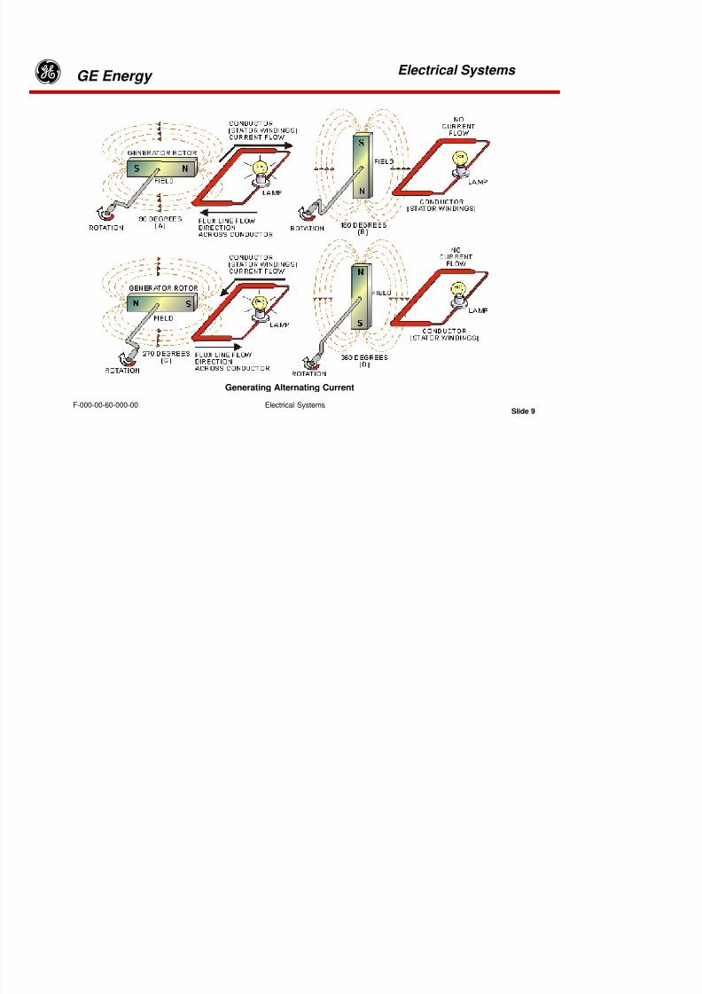
8/18/2019 71777896 - LM6000 Package Familiarization & Operations.pdf
http://slidepdf.com/reader/full/71777896-lm6000-package-familiarization-operationspdf 371/786
Electrical Systems
gGE Energy Electrical Systems
Slide 7F-000-00-60-000-00
Generating Current Flow Using a Magnet
8/18/2019 71777896 - LM6000 Package Familiarization & Operations.pdf
http://slidepdf.com/reader/full/71777896-lm6000-package-familiarization-operationspdf 372/786
Electrical Systems
gGE Energy Electrical Systems
Slide 8F-000-00-60-000-00
By the year 1820, the question was answered and quantified by an experiment similar to thatillustrated in (A) above. Relative motion between a magnet and an electrical conductor
produced electric current flow. The demonstration also proved the rate of motion and thestrength of the magnetic field relate to the amount of current induced into the conductor.
A mechanical analogy, illustrated in (B) shows a pump in a liquid circuit with a valveblocking flow when closed and allowing flow when open. In the electrical circuit of (A), the
switch prevents electric current flow when open and allows flow when closed. Mechanicalenergy is required to rotate the pump shaft; just as moving the magnet, the conductor orboth also require mechanical energy in the production of electric current.

8/18/2019 71777896 - LM6000 Package Familiarization & Operations.pdf
http://slidepdf.com/reader/full/71777896-lm6000-package-familiarization-operationspdf 373/786
Electrical Systems
gGE Energy Electrical Systems
Slide 9F-000-00-60-000-00
Generating Alternating Current
8/18/2019 71777896 - LM6000 Package Familiarization & Operations.pdf
http://slidepdf.com/reader/full/71777896-lm6000-package-familiarization-operationspdf 374/786
Electrical Systems
gGE Energy Electrical Systems
Slide 10F-000-00-60-000-00
Generating Alternating Current
This theory of relative motion leads to the operation of the conceptual generator illustratedabove. As the permanent magnet is rotated by the hand-crank, its poles alternate in approachingthe conductor; i.e., south followed by north, followed by south, etc.
The concentration of magnetic flux lines at the poles of the rotating magnet induce maximumcurrent as they pass the conductor, diminish to minimum, and then reverse and becomemaximum in the opposite direction each half-cycle. The induced current flow through the load,then, also reverses each half-cycle, and if the crank is rotated at a constant speed, the
generated waveform is sinusoidal.
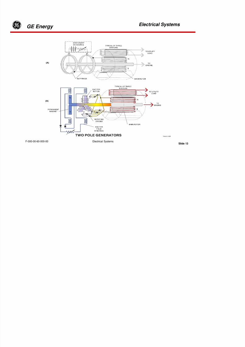
8/18/2019 71777896 - LM6000 Package Familiarization & Operations.pdf
http://slidepdf.com/reader/full/71777896-lm6000-package-familiarization-operationspdf 375/786
Electrical Systems
gGE Energy Electrical Systems
Slide 11F-000-00-60-000-00
Generating Three-phase Current

8/18/2019 71777896 - LM6000 Package Familiarization & Operations.pdf
http://slidepdf.com/reader/full/71777896-lm6000-package-familiarization-operationspdf 376/786
Electrical Systems
gGE Energy Electrical Systems
Slide 12F-000-00-60-000-00
Generating Three-phase Current
We can expand on this concept of single-phase current by introducing two additionalconductors, and space each one 120 mechanical degrees apart. Illustration A shows
how three independent circuits can be generated for each revolution of the magnet toproduce three sinusoidal waveforms as shown in (B). This concept is called three-phase generation and is commonly used throughout the electric generation industry.
Coils and Magnetic Flux Density
Practical application of the single- and three-phase generation of electricalcurrent, however, means addressing two additional requirements: (1) a methodof controlling its output voltage and (2) a means of generating more power thancan be produced using a rotating permanent magnet and single conductors as
stators. The idea of the conductors wound into coils provides the solution.

8/18/2019 71777896 - LM6000 Package Familiarization & Operations.pdf
http://slidepdf.com/reader/full/71777896-lm6000-package-familiarization-operationspdf 377/786
Electrical Systems
gGE Energy Electrical Systems
Slide 13F-000-00-60-000-00

8/18/2019 71777896 - LM6000 Package Familiarization & Operations.pdf
http://slidepdf.com/reader/full/71777896-lm6000-package-familiarization-operationspdf 378/786
Electrical Systems
gGE Energy Electrical Systems
Slide 14F-000-00-60-000-00
TWO-POLE GENERATORS
The figure below illustrates brush and brushless-type generators that allow control of rotor fieldstrength and, therefore, control of the current that is induced into the three stator windings installedat 120 mechanical degree intervals around the rotor.
It should be noted that, because the polarity of the brush contacts remains the same regardless ofthe angle of rotation of the rotor, the assignment of north and south poles on the rotor also do notchange. The arrangement, therefore, provides a rotating north and south pole magnet with
controllable field strength to allow control of the voltage induced into the stator windings.
Brush-Type Generators
A brush-type generator uses a battery and brushes in contact with slip rings to supplymagnetizing current for the rotor windings. The magnetizing current is referred to as excitationcurrent . A variable resistor in the stationary battery circuit provides regulation of the excitationcurrent flow through the rotating coil, thus allowing control of the magnitude of the rotatingmagnetic field of the rotor.
8/18/2019 71777896 - LM6000 Package Familiarization & Operations.pdf
http://slidepdf.com/reader/full/71777896-lm6000-package-familiarization-operationspdf 379/786
Electrical Systems
gGE Energy Electrical Systems
Slide 15F-000-00-60-000-00
Brushless-Type Generators
A brushless excitation scheme provides magnetic linking of the stationary and rotating parts of
the machine without using brushes. A permanent magnet of high permeability is driven by theprime mover (or engine) as it drives the rotor. Coils having low permeability in close proximity tothe rotating permanent magnet are induced with a current that alternates as the permanentmagnetic poles rotate.
The field strength of the exciter field windings is therefore controllable by adjustment of thevariable resistor. A set of three windings, each spaced at 120 mechanical degree intervals onthe rotor of the machine called the exciter rotor, are induced with a current with an amplitude
proportional to the adjustable current flow through the stationary exciter field windings.
The output of the three windings on the exciter rotor is a three-phase alternating current. Thisadjustable current is applied to a set of diodes attached to the rotor to produce a DC current thatis applied to the main rotor.
The AC current is allowed to flow in only one direction through stationary diodes. The
diodes then convert the AC current generated by the rotating permanent magnet into DCcurrent that is applied through a variable resistor to a set of stationary coils called exciterfield windings.
8/18/2019 71777896 - LM6000 Package Familiarization & Operations.pdf
http://slidepdf.com/reader/full/71777896-lm6000-package-familiarization-operationspdf 380/786
Electrical Systems
gGE Energy Electrical Systems
Slide 16F-000-00-60-000-00
Exciter Diode Wiring

8/18/2019 71777896 - LM6000 Package Familiarization & Operations.pdf
http://slidepdf.com/reader/full/71777896-lm6000-package-familiarization-operationspdf 381/786
Electrical Systems
gGE Energy Electrical Systems
Slide 17F-000-00-60-000-00
BRUSH GENERATOR EXCITER CIRCUITRY
The three-phase exciter voltage is rectified by 12 diodes in the full-wave rectification bridge circuitshown above. The output from the diode bridge is a constant DC current flowing through the Main
Rotor Windings. The current creates a massive magnetic field around the rotor.
Diodes in the bridge circuit above could fail “open” or “shorted”. If a diode fails “open”, then currentwould continue to flow through the parallel diode in that “leg”, and the bridge would continue operating
without interruption. If a diode fails “shorted”, then the fuse in series will blow, and the circuitcontinues to operate. However, if two diodes in the same “leg” should fail, then the generator wouldshutdown on loss of excitation.
8/18/2019 71777896 - LM6000 Package Familiarization & Operations.pdf
http://slidepdf.com/reader/full/71777896-lm6000-package-familiarization-operationspdf 382/786
Electrical Systems
gGE Energy Electrical Systems
Slide 18F-000-00-60-000-00
The exciter also contains a radio transmitter, powered by the rectified DC voltage. If a rotor ground faultshould occur, then the radio signal would turn off. This loss of signal is detected by a receiver in the controlpanel, causing a “Rotor Ground Fault” alarm. Diode failure is detected by a “ripple” induced in the exciter
field by the unbalanced voltage.
Exciter Diode Wiring
The rotating permanent magnets and the windings that surround them in the brushless exciterconfiguration are referred-to as components of the permanent magnetic alternator (PMA) orpermanent magnet generator (PMG). The PMA/PMG alternating current output is applied to an off-generator unit that provides the rectification and regulation functions indicated by the stationarydiodes and variable resistor in the (B) illustration above. The off-engine package is referred-to as theMicro Automatic Voltage Regulator or MAVR.
As the A, B, and C phases from the exciter rotor alternate through positive and negative cycles, thepositive half cycles are conducted from each diode’s anode to cathode and appear on the positiveoutput side of the rectifier. The negative half cycles conduct from each diode’s cathode to anode andappear on the negative output side of the rectifier.
Exciter Diode Wheel
Typically, the rotating diodes are mounted on a wheel. The electrical schematic below diagrams thewiring of the three-phase rectifier assembly. The positive and negative outputs from the rectifier areconnected to the main rotor windings through a bore in the generator shaft.
8/18/2019 71777896 - LM6000 Package Familiarization & Operations.pdf
http://slidepdf.com/reader/full/71777896-lm6000-package-familiarization-operationspdf 383/786

8/18/2019 71777896 - LM6000 Package Familiarization & Operations.pdf
http://slidepdf.com/reader/full/71777896-lm6000-package-familiarization-operationspdf 384/786
Electrical Systems
gGE Energy Electrical Systems
Slide 20F-000-00-60-000-00
BRUSHLESS EXCITATION
Permanent Magnet Generator
To begin with, a source of Utility Voltage is required. It is generated with a “Permanent Magnet
Generator” (PMG). The PMG has 16 permanent magnets on a wheel mounted to the generator shaft.The magnets are set with alternating North…South…North poles facing outward.
Exciter Stator Coil – The output of the Voltage Regulator creates a DC magnetic field around theExciter Stator Coil. The strength of this magnetic field is controlled by the SCR in the VoltageRegulator.
PMG Stator Coil
The PMG Stator Coil is mounted in the Exciter housing. The Utility Voltage need is generated in
this coil by the PMG. Actually, the voltage is a little higher than needed. The voltage is rectifiedand controlled by the Voltage Regulator.
A coil is mounted on the generator frame. As the shaft turns, the magnetic lines of force from eachmagnet cut through the coils of the PMG Stator Coil and create an AC voltage in the coil. With the shaftrotating at 3600 RPM (the speed for 60 Hz generation), approximately 270 Volts at 480 Hz is generated inthe PMG Stator Coil. This will be utilized as the Utility Voltage to create a much larger voltage in the MainGenerator Stator Coils.
8/18/2019 71777896 - LM6000 Package Familiarization & Operations.pdf
http://slidepdf.com/reader/full/71777896-lm6000-package-familiarization-operationspdf 385/786
Electrical Systems
gGE Energy Electrical Systems
Slide 21F-000-00-60-000-00
Exciter Rotor Coils (3) - The Exciter Rotor Coils rotate through the magnetic field around the ExciterStator Coil. A 3-phase voltage is built up in the Exciter Rotor Coils as they cut through the magneticlines of force. Significantly, energy is transferred from the stationary coil to the rotating coils without
brushes. This magnetic transfer of energy to the rotating shaft is the heart of “Brushless Excitation”.
Generator Stator Coils – As the rotor turns, the magnetic lines of force cut through the GeneratorStator Coils and create the generator’s high-voltage, 3-phase AC output.
Main Rotor Coil – Rectified DC voltage from the rotating diodes forces DC current through the MainRotor windings, creating a massive magnetic field around the rotor. The strength of the field isdetermined by the amount of current flowing through the Main Rotor Coil.
Rotating Diodes (12) – The AC voltage built up in the Exciter Rotor Coils is rectified by diodesmounted on a wheel rotating with the generator shaft. This provides a DC voltage to thewindings of the Main Rotor Coil. A fuse is placed in series with each diode. If the diode should failshorted, the fuse will blow and take the diode out of the circuit.

8/18/2019 71777896 - LM6000 Package Familiarization & Operations.pdf
http://slidepdf.com/reader/full/71777896-lm6000-package-familiarization-operationspdf 386/786
Electrical Systems
gGE Energy Electrical Systems
Slide 22F-000-00-60-000-00

8/18/2019 71777896 - LM6000 Package Familiarization & Operations.pdf
http://slidepdf.com/reader/full/71777896-lm6000-package-familiarization-operationspdf 387/786
Electrical Systems
gGE Energy Electrical Systems
Slide 23F-000-00-60-000-00
REAL POWER, VARS, AND POWER FACTOR
Types of Electrical Power
A motor requires two different types of electrical power to operate – both Watts and VARs. Thegenerator supplies both these forms of energy.
VARs are “Reactive Power”. VARs are not consumed. VARs are “stored by the load”, eitherin magnetic flux or in the charge on capacitors. The energy stored in VARs is returned to the
circuit whenever the AC voltage changes polarity.
Watts are “Real Power”. Watts do the work. Watts are consumed by the load and are changedinto another form of energy. A motor converts Watts into rotating mechanical energy.
8/18/2019 71777896 - LM6000 Package Familiarization & Operations.pdf
http://slidepdf.com/reader/full/71777896-lm6000-package-familiarization-operationspdf 388/786
Electrical Systems
gGE Energy Electrical Systems
Slide 24F-000-00-60-000-00
The generator’s output is called “Apparent Power”, consisting of Volts and Amps. The nature of theload determines how the generator’s output will be divided between Watts and VARs. Dependingon the situation, the generator’s output may be used as:
· All Watts
· All VARs
A combination of Watts and VARs
Power Factor = Cosine θ
Power Factor is the percentage of the generator’s output that is doing real work. A .85 LaggingPower Factor means that 85% of the generator’s output is being consumed as Watts. Theremainder of the generator’s output is creating magnetic fields around the coils of motors.

8/18/2019 71777896 - LM6000 Package Familiarization & Operations.pdf
http://slidepdf.com/reader/full/71777896-lm6000-package-familiarization-operationspdf 389/786
Electrical Systems
gGE Energy Electrical Systems
Slide 25F-000-00-60-000-00
GENERATOR CAPABILITY DIAGRAM

8/18/2019 71777896 - LM6000 Package Familiarization & Operations.pdf
http://slidepdf.com/reader/full/71777896-lm6000-package-familiarization-operationspdf 390/786
Electrical Systems
gGE Energy
Electrical Systems
Slide 26F-000-00-60-000-00
GENERATOR CAPABILITY DIAGRAM
How much power can an operator get from his generator without overheating? The curves above showthe maximum capability of a generator at various temperatures and power factors. To prevent
overheating, the operator should keep the generator output within the curves. (When ambienttemperature is between 150 C and 400 C it is necessary to interpolate.)
In the “Over-Excited region of the curve (bottom portion) the generator is supplying both Watts andVARs. At .85 Lagging Power Factor on the 150 C curve the generator can supply as much as 60.5 MWof Real Power and 37.5 MVAR to support magnetic fields.
Remember – YOU MAKE VARs WITH THE VOLTAGE REGULATOR
If the generator is powering a purely resistive load (0 on the left index), with 150 C ambienttemperature, the generator can provide 71 MW of power. As motors are added to the load, the power
factor goes down, and the generator must provide VAR support in addition to MW. This is done byOver-Exciting the generator . To export VARs, the generator voltage is increased until it is higher thanthe grid. VARs then flow from the generator to the grid.

8/18/2019 71777896 - LM6000 Package Familiarization & Operations.pdf
http://slidepdf.com/reader/full/71777896-lm6000-package-familiarization-operationspdf 391/786
Electrical Systems
gGE Energy
Electrical Systems
Slide 27F-000-00-60-000-00
MECHANICAL COUPLING
Grid and Generator phases are aligned.
No power flows in either direction.
Generator leads Grid.
Gen. exports Watts (Real Power) to Grid.

8/18/2019 71777896 - LM6000 Package Familiarization & Operations.pdf
http://slidepdf.com/reader/full/71777896-lm6000-package-familiarization-operationspdf 392/786
Electrical Systems
gGE Energy
Electrical Systems
Slide 28F-000-00-60-000-00
MECHANICAL COUPLING ANALOGY
If you were to observe two machines – A and B – that were coupled together with a rotating
shaft it would appear that both machines are turning at the same speed. If a straight line hadbeen drawn along the length of the coupling when the machines were stopped and we observeit during operation with a stroboscopic light (used to “stop” the motion of the rotatingcoupling) there would be “twist” or deflection in the coupling.
When power is being transmitted, there will be a deflection or “twist” in the coupling, creatinga phase angle between the two ends. The machine with the leading phase angle is the driver.The other machine is “driven”. The phase angle between the ends of the coupling isproportional to the load. When the load increases there will be more “twist” in the couplingand a greater phase angle between the ends.
8/18/2019 71777896 - LM6000 Package Familiarization & Operations.pdf
http://slidepdf.com/reader/full/71777896-lm6000-package-familiarization-operationspdf 393/786
Electrical Systems
gGE Energy
Electrical Systems
Slide 29F-000-00-60-000-00
Now, let’s look at an electric generator synchronized to the grid. When the circuit breaker closes, thegenerator is latched to the grid by magnetic forces. The generator is forced to turn at exactly the samespeed as the grid – (just as the two ends of the coupling above turn at the same speed).
To export Watts (Real Power) to the grid, the fuel valve is opened and attempts to make the generator
turn faster. (It cannot – for the generator is coupled to the grid.) The fuel added by the operatorcreates additional torque in the turbine. This forces the generator’s shaft slightly ahead of the grid,creating a leading phase angle. The generator is now the “driver” and it exports Watts (Real Power)into the grid. The greater the leading phase angle – the more Watts flow from the generator to the grid.
8/18/2019 71777896 - LM6000 Package Familiarization & Operations.pdf
http://slidepdf.com/reader/full/71777896-lm6000-package-familiarization-operationspdf 394/786
Electrical Systems
gGE Energy
Electrical Systems
Slide 30F-000-00-60-000-00
STORING ENERGY
A flywheel stores mechanical energy A coil stores magnetic energy
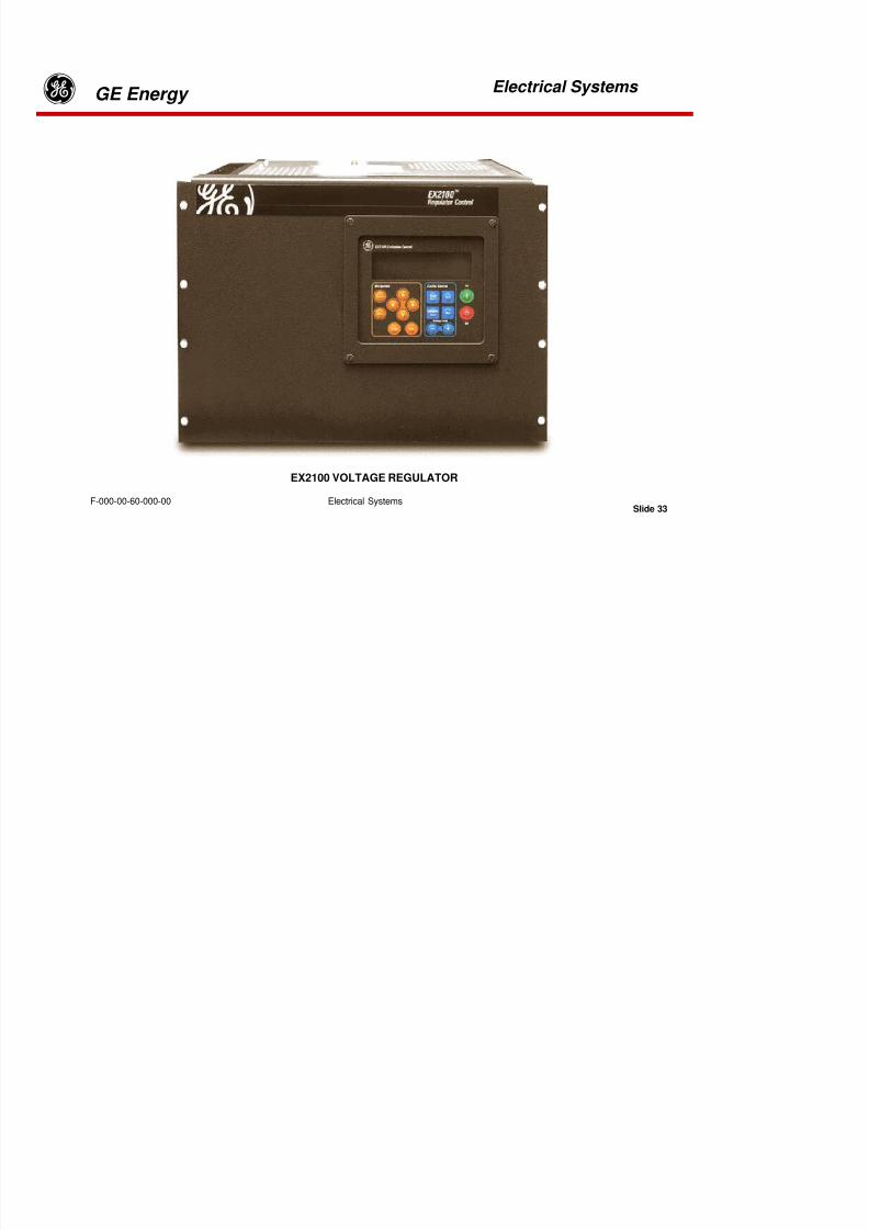
8/18/2019 71777896 - LM6000 Package Familiarization & Operations.pdf
http://slidepdf.com/reader/full/71777896-lm6000-package-familiarization-operationspdf 395/786
Electrical Systems
gGE Energy
Electrical Systems
Slide 31F-000-00-60-000-00
Storing energy
Suppose that you had a crank and were trying to rotate a large flywheel. After straining a bit youcould get it moving. After you had cranked hard for a while you could get the flywheel turning rapidly.When you stopped cranking, the flywheel would continue turning until bearing friction and airresistance slowed it to a stop.
You put mechanical energy into the flywheel to make it turn. Then that energy came back out in theform of bearing heat and air movement. The flywheel didn’t consume energy. You got back all theenergy you put in.
Now let’s look at storing electrical energy. As we have said, VARs are required to createmagnetic fields in coils. When an AC current is increasing through a coil, the magnetic fieldaround the coil expands. When the current begins to decrease, the magnetic field collapses. Asthe field collapses, it feeds back into the system the energy that created the field – just as the
flywheel feeds energy back when you stop cranking. There is no net loss of electrical energy,except for a small heating loss in the wires and the coil.
8/18/2019 71777896 - LM6000 Package Familiarization & Operations.pdf
http://slidepdf.com/reader/full/71777896-lm6000-package-familiarization-operationspdf 396/786
Electrical Systems
gGE Energy
Electrical Systems
Slide 32F-000-00-60-000-00
VARs don’t consume real power. VARs just store energy momentarily in coils (or capacitors).
VAR’s also stabilize the operation and control of power grids. Grid dispatchers often call on power
producers to export VAR’s to support voltage conditions on the grid.
The units run as generators during the day, providing MW when demand is highest. At night, thegas turbine is shut off, the clutch disengaged, and the generator continues to run as a motor,powered by the grid. By raising or lowering the excitation of the generator, the operator canimport or export VARs to correct power factor on the grid.
SYNCHRONOUS CONDENSERS
Several LM6000 packages have been installed recently with “Synchronous Condenser” capabilities.For this modification, a clutch is included between the gas turbine and the generator, and additionalprogramming for the protective relays is provided.

8/18/2019 71777896 - LM6000 Package Familiarization & Operations.pdf
http://slidepdf.com/reader/full/71777896-lm6000-package-familiarization-operationspdf 397/786
Electrical Systems
gGE Energy
Electrical Systems
Slide 33F-000-00-60-000-00
EX2100 VOLTAGE REGULATOR
8/18/2019 71777896 - LM6000 Package Familiarization & Operations.pdf
http://slidepdf.com/reader/full/71777896-lm6000-package-familiarization-operationspdf 398/786
Electrical Systems
gGE Energy
Electrical Systems
Slide 34F-000-00-60-000-00
AUTOMATIC VOLTAGE REGULATOR (AVR)
The Automatic Voltage Regulator (AVR) controls the current flow in the Exciter Stator Coils.Raising the current in these coils causes an increase in generator output voltage.
The AVR operates on 24 VDC control power, and it receives a 270 VAC, 480 Hz powerinput from the Permanent Magnet Generator (PMG). The AVR rectifies this AC input withSelenium-Controlled-Rectifiers (SCRs) to produce a controlled DC output to the Exciter
Stator Coils.

8/18/2019 71777896 - LM6000 Package Familiarization & Operations.pdf
http://slidepdf.com/reader/full/71777896-lm6000-package-familiarization-operationspdf 399/786
Electrical Systems
gGE Energy
Electrical Systems
Slide 35F-000-00-60-000-00
AUTOMATIC VOLTAGE REGULATOR (AVR)
Auto – Manual Modes:
The AVR has two operating modes – Auto and Manual. The Auto mode compares the generator’soutput voltage with a set-point established by the operator. As the load on the generator changes,the AVR increases or decreases the output to correct any deviation from its set-point. The AVR willnormally operate in this Auto mode.
The changeover from Auto-to-Manual mode is automatic and “bumpless”, since the Manualsection “tracks the Auto”. However, changing back from Manual-to-Auto is not automatic. Theoperator must balance the Manual and Auto excitation levels with the Null-Balance Ammeter onthe face of the control panel before turning the switch to change back from Manual-to-Auto.
However, if the Auto mode should fail, the AVR will shift to its Manual mode. The Manual modemaintains the AVR output at the level immediately preceding the transfer, unless the operatormanually changes the set-point. The output voltage from the generator will vary – up or down as theload on the generator changes. Frequent operator corrections may be necessary while operating inManual mode.
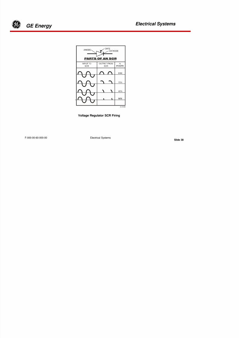
8/18/2019 71777896 - LM6000 Package Familiarization & Operations.pdf
http://slidepdf.com/reader/full/71777896-lm6000-package-familiarization-operationspdf 400/786
Electrical Systems
gGE Energy
Electrical Systems
Slide 36F-000-00-60-000-00
Additional AVR Features
In addition to controlling the excitation and generator output voltage, the AVR includes the followingoperating features:
Overflux Limiter Prevents overexcitation during startup.
Current Limiter Prevents over-current operation
Over-Excitation Limiter Prevents over-heating of generator, but permits brief over-excitation
8/18/2019 71777896 - LM6000 Package Familiarization & Operations.pdf
http://slidepdf.com/reader/full/71777896-lm6000-package-familiarization-operationspdf 401/786
Electrical Systems
gGE Energy
Electrical Systems
Slide 37F-000-00-60-000-00
Under-Excitation Limiter Prevents unsafe underexcitation and loss of synchronization
Soft Voltage Buildup Allows gradual voltage buildup during starting, withoutovershoot
Control Card Monitor Continually checks the operating health of the control cards
Diode Failure Indicator Monitors exciter field current ripple and provides alarm on diode failure.
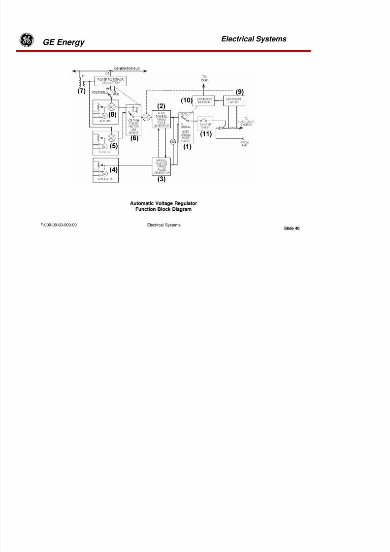
8/18/2019 71777896 - LM6000 Package Familiarization & Operations.pdf
http://slidepdf.com/reader/full/71777896-lm6000-package-familiarization-operationspdf 402/786
Electrical Systems
gGE Energy
Electrical Systems
Slide 38F-000-00-60-000-00
Voltage Regulator SCR Firing
8/18/2019 71777896 - LM6000 Package Familiarization & Operations.pdf
http://slidepdf.com/reader/full/71777896-lm6000-package-familiarization-operationspdf 403/786
Electrical Systems
gGE Energy
Electrical Systems
Slide 39F-000-00-60-000-00
Voltage Regulator
The Voltage Regulator rectifies the AC voltage from the PMG Stator Coil and limits the totalamount of energy flowing to the Exciter Stator Coil. The Voltage Regulator controls the
energy flow with a special device called a “Silicon Controlled Rectifier” (SCR). The specialrectifier includes an extra connection called a “Gate”. A brief electrical pulse on the Gateturns the SCR “On”, allowing current to pass through the SCR from anode to cathode. Thecurrent stays “On” until the end of the half-cycle.
In its “Full Power” position the SCR lets all the energy in a complete half-wave to passthrough. To reduce the output power, the SCR “turns on” the output later and later in thecycle. This delay lets smaller and smaller amounts of energy pass through the SCR. The
output voltage from the SCR builds a DC magnetic field around the “Exciter Stator Coils”.

8/18/2019 71777896 - LM6000 Package Familiarization & Operations.pdf
http://slidepdf.com/reader/full/71777896-lm6000-package-familiarization-operationspdf 404/786
Electrical Systems
gGE Energy
Electrical Systems
Slide 40F-000-00-60-000-00
Automatic Voltage RegulatorFunction Block Diagram

8/18/2019 71777896 - LM6000 Package Familiarization & Operations.pdf
http://slidepdf.com/reader/full/71777896-lm6000-package-familiarization-operationspdf 405/786
Electrical Systems
gGE Energy
Electrical Systems
Slide 41F-000-00-60-000-00
The following is a typical AVR Layout and basic functions.
The Automatic Voltage Regulator (AVR) controls and monitors generator excitation current. It alsoprotects the generator with visual and audible alarms, automatic mode switching, and with theautomatic trip of the generator output circuit breaker when necessary. The AVR is a microprocessor
controlled and digitally implemented unit that is housed in an electronics rack mounted in the turbinecontrol panel. The diagram illustrates its safety features and interconnection with controls mounted onthe turbine control panel.
SCR gating pulses are generated by automatic and manual firing pulse generators as indicated in theMAVR functional block diagram. The automatic/manual selector (1) is a spring-loaded, momentary,center-off, control switch. It latches in either the automatic or manual position and thereby connectsthe automatic (2) or manual (3) gating pulse generator to the SCR gate. The pulse generators areinterlinked to track each other such that switching between them produces a bumpless transfer.
The AC output of the generator-driven permanent magnet alternator (PMA) or permanent magnet
generator (PMG) is shown on the right-hand side of the diagram. This output is applied to a silicon-controlled rectifier (SCR) that performs both rectification and regulation of the PMA/PMG output. Theoutput of the SCR becomes the driving current for the generator exciter. Six front panel controls,mounted on the turbine control panel, interface with the AVR circuitry and allow control of the SCR.

8/18/2019 71777896 - LM6000 Package Familiarization & Operations.pdf
http://slidepdf.com/reader/full/71777896-lm6000-package-familiarization-operationspdf 406/786
Electrical Systems
gGE Energy
Electrical Systems
Slide 42F-000-00-60-000-00
A null meter between the manual and automatic pulse generator channels allows operators todetect a difference in the outputs should a difference occur. When operating normally, the meterwill indicate zero difference between the two channel outputs.
When operated in the automatic mode, the raise/lower contacts (5 & 8) are functional for theselected mode of operation. Voltage, power factor or VAR control selections are available (6).
When the unit is operated in the manual mode, raise/lower contacts (4) on the turbine control panellabeled, Manual Raise/Lower , adjust the excitation current.
8/18/2019 71777896 - LM6000 Package Familiarization & Operations.pdf
http://slidepdf.com/reader/full/71777896-lm6000-package-familiarization-operationspdf 407/786
Electrical Systems
gGE Energy
Electrical Systems
Slide 43F-000-00-60-000-00
In voltage mode, the operator selects a voltage setpoint value through the motor operatedpotentiometer (5) control labeled Voltage Raise/Lower on the turbine control panel. In this mode,the generator output voltage from a potential transformer (PT) (7) is compared with an operatoradjustable setpoint resulting in an error voltage that is applied to the automatic gating pulsegenerator (2). The control loop, thus formed, acts to drive the measured value of voltage to equalthe set point.
In power factor mode, the operator selects a power factor setpoint value through the motoroperated potentiometer control (8) labeled Power Factor (VAR) Raise/Lower on the turbinecontrol panel. In this mode, the measured Power Factor from the Power Factor/VARcalculator is compared with an operator adjustable setpoint, resulting in an error voltagethat is applied to the automatic gating pulse generator. The control loop, thus formed, actsto drive the measured value of power factor to equal the setpoint.
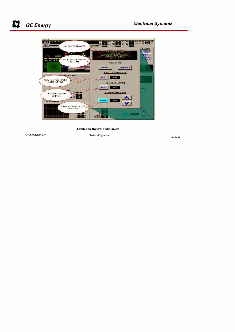
8/18/2019 71777896 - LM6000 Package Familiarization & Operations.pdf
http://slidepdf.com/reader/full/71777896-lm6000-package-familiarization-operationspdf 408/786
Electrical Systems
gGE Energy
Electrical Systems
Slide 44F-000-00-60-000-00
The excitation limiter (9) senses excitation current. When safe boundary conditions areviolated, it attempts to lower the excitation current through a summing junction at the input tothe automatic SCR firing pulse generator and provides an alarm indication on the front panel ofthe MAVR. If, after a time delay, the excitation current remains outside safe limits, the excitationlimiter signals the excitation monitor (10) to switch to the manual SCR firing pulse generatorchannel and initiates a second time delay. Following the second time delay, the excitation
monitor signals the Digital Generator Protection system to open the 52G circuit breaker.
In VAR mode, the operator selects a VAR setpoint value through the motor operatedpotentiometer control (8) labeled Power Factor/VAR Raise Lower on the turbine control panel. Inthis mode, the measured VAR output from the Power Factor/VAR calculator is compared with anoperator adjustable setpoint, resulting in an error voltage that is applied to the automatic gating
pulse generator. The control loop, thus formed, acts to drive the measured value of VAR to equalthe setpoint.
8/18/2019 71777896 - LM6000 Package Familiarization & Operations.pdf
http://slidepdf.com/reader/full/71777896-lm6000-package-familiarization-operationspdf 409/786
Electrical Systems
gGE Energy
Electrical Systems
Slide 45F-000-00-60-000-00
It should be noted that operators are alerted and allowed a time to react to over or under-excitation current conditions before the 52G breaker open signal occurs. To avoid marginalconditions, operators should monitor the generator operating point on the generator capabilitiesdiagram.
At startup, the REGULATOR ON/OFF switch (11) (ES, Generator Excitation) should be in theON position and the EXCITATION MODE SELECT switch (1) should be in either the AUTO-VOLTAGE OR MANUAL position. At the end of the START-UP sequence, if the operator haschosen MANUAL SYNCH mode, the sequencing system will generate an operator message“Start-up sequence complete. Ready for manual synchronization and loading.” If theoperator has chosen AUTOMATIC SYNCH mode, the sequencing system will adjust theMAVR controls and the engine throttle controls, and close the 52G generator output circuit
breaker. At this time the operator can adjust the engine throttle to achieve the desiredloading.

8/18/2019 71777896 - LM6000 Package Familiarization & Operations.pdf
http://slidepdf.com/reader/full/71777896-lm6000-package-familiarization-operationspdf 410/786
Electrical Systems
gGE Energy
Electrical Systems
Slide 46F-000-00-60-000-00
Excitation Control HMI Screen

8/18/2019 71777896 - LM6000 Package Familiarization & Operations.pdf
http://slidepdf.com/reader/full/71777896-lm6000-package-familiarization-operationspdf 411/786
Electrical Systems
gGE Energy
Electrical Systems
Slide 47F-000-00-60-000-00
Excitation ControlsThe LM6000 R60 Gas Turbine / Generator Package excitation control system includes several componentsincluding the generator’s Permanent Magnet Generator (PMG), the generator’s Main Exciter Field, TheAutomatic Voltage Regulator (AVR), Zero Speed Detection Circuit (A17), and a Rotor Ground Fault Monitor(RGF). Persons tasked with operating this system should have a thorough understanding of power
generation systems and be familiar with Drawing XXXX-YY-ZZZ037 System Schematic GeneratorExcitation as well as all other associated system drawings.
The automatic voltage regulator is the heart of this system and may be controlled in AUTOMATICEXCITATION mode from a local or remote HMI or at the TCP local panel switches. AUTO orMANUAL Mode is selected at either a local or remote HMI by depressing the AUTO / MAN togglebutton on the AVR portion of the Control Screen or at the local TCP front panel “Regulator,Auto/Manual Voltage” switch (AVR). The AVR switch at the TCP front panel has priority over allother AUTO / MAN control locations. This provides control priority to the operator nearest thecontrolled equipment.

8/18/2019 71777896 - LM6000 Package Familiarization & Operations.pdf
http://slidepdf.com/reader/full/71777896-lm6000-package-familiarization-operationspdf 412/786
Electrical Systems
gGE Energy
Electrical Systems
Slide 48F-000-00-60-000-00
The AVR should always be operated in the Automatic Mode unless an equipment or system failureprevents it. When the AVR is in Manual Mode it will not be able to adjust to electrical system variationsand so must be monitored and adjusted continually. If it is not, system conditions could develop that arebeyond the equipments capability resulting in the unit tripping or in equipment damage.
At the TCP the “Control Selection Switch” in LOCAL permits control inputs to be readfrom the front panel controls or the “LOCAL” Human Machine Interface (HMI). With thisswitch in REMOTE control inputs and adjustments can only be made at a remote HMI orthrough a DCS, SCS or other distributive control system interface.

8/18/2019 71777896 - LM6000 Package Familiarization & Operations.pdf
http://slidepdf.com/reader/full/71777896-lm6000-package-familiarization-operationspdf 413/786
Electrical Systems
gGE Energy
Electrical Systems
Slide 49F-000-00-60-000-00
Automatic AVR OperationTo operate the AVR in Automatic mode the correct control location described above must beselected.
The “AVR IN AUTO” mode should be verified on the HMI (See Fig. 1). If the AVR is not in auto itshould be switched to auto either at the HMI toggle button or at the momentary Generator Exciter
mode switch on the TCP front panel.
Note that when the HMI “AVR Control” button displays “manual” it means the AVR is currentlyin the AUTO mode and will go into “MANUAL” mode when the button is pushed.
Verify the HMI indicates the “AVR IN VOLTAGE CONTROL”(See Fig. 1). With the AVR in Automode there are three “Control Modes” available. The first is the Voltage Control Mode. Thismode is the base operating mode for the AVR. In this mode excitation is automatically adjustedto maintain the generator output voltage equivalent to a voltage set point.
8/18/2019 71777896 - LM6000 Package Familiarization & Operations.pdf
http://slidepdf.com/reader/full/71777896-lm6000-package-familiarization-operationspdf 414/786
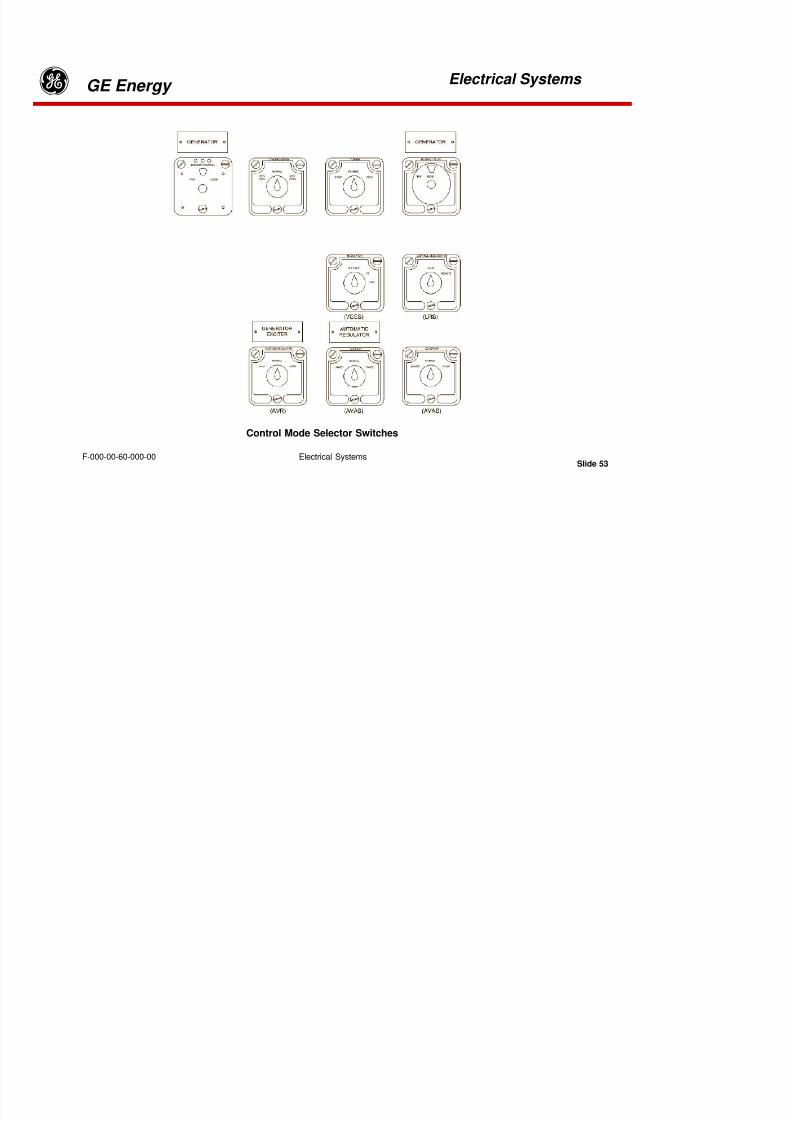
8/18/2019 71777896 - LM6000 Package Familiarization & Operations.pdf
http://slidepdf.com/reader/full/71777896-lm6000-package-familiarization-operationspdf 415/786
Electrical Systems
gGE Energy
Electrical Systems
Slide 51F-000-00-60-000-00
With the AVR in Auto mode the set point may be adjusted from the HMI screen with the up anddown adjustment buttons (See Figure 2). The second mode is the Power Factor (PF) Control Mode.This mode allows the operator to control the generator output based upon an adjustable PowerFactor set point. In this mode excitation is adjusted to maintain the generator output to a Power
Factor set point within the operational limits of the generator.
To select between these control modes the enable button next to the control mode label on the HMIscreen must be pressed. When the mode enable button is highlighted in light blue the AVR is in thatcontrol mode.
The AVR can only be in one control mode at any given time. Changing directly between PF and VARcontrol modes is not allowed. Therefore if the operator desires to change control modes he must firstenable the voltage control mode and then select PF or VAR control.
The third mode is the VAR Control Mode. This mode allows the operator to control thegenerator output based upon an adjustable VAR set point. In this mode excitation is adjustedto maintain the generator output to a VAR set point that falls within the operational limits of
the generator.

8/18/2019 71777896 - LM6000 Package Familiarization & Operations.pdf
http://slidepdf.com/reader/full/71777896-lm6000-package-familiarization-operationspdf 416/786
Electrical Systems
gGE Energy
Electrical Systems
Slide 52F-000-00-60-000-00
When PF or VAR control is active the set point button will appear to the right of thecontrol mode label on the HMI. When the set point button is pushed for the selected AVRcontrol mode a window appears where the new set point can be entered using the HMI
keyboard. Press the “enter” key or click “OK” to initiate the new set point.
These control modes can also be selected from the TCP front panel with the “PowerFactor/VAR Control Enable Switch” (VCES) (See Figure 3). The set points for each mode
can be adjusted with the “Automatic Voltage Regulator Adjust Switch” (AVAS) (SeeFigure 3).
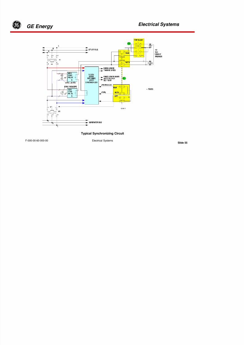
8/18/2019 71777896 - LM6000 Package Familiarization & Operations.pdf
http://slidepdf.com/reader/full/71777896-lm6000-package-familiarization-operationspdf 417/786
Electrical Systems
gGE Energy
Electrical Systems
Slide 53F-000-00-60-000-00
Control Mode Selector Switches
8/18/2019 71777896 - LM6000 Package Familiarization & Operations.pdf
http://slidepdf.com/reader/full/71777896-lm6000-package-familiarization-operationspdf 418/786
8/18/2019 71777896 - LM6000 Package Familiarization & Operations.pdf
http://slidepdf.com/reader/full/71777896-lm6000-package-familiarization-operationspdf 419/786
Electrical Systems
gGE Energy
Electrical Systems
Slide 55F-000-00-60-000-00
Typical Synchronizing Circuit
8/18/2019 71777896 - LM6000 Package Familiarization & Operations.pdf
http://slidepdf.com/reader/full/71777896-lm6000-package-familiarization-operationspdf 420/786
Electrical Systems
gGE Energy
Electrical Systems
Slide 56F-000-00-60-000-00
Synchronization Circuitry
Synchronization circuitry is implemented in the GE Energy control system to allow operators tomatch the voltage, frequency, and phase of the generator voltage to the voltage on the oppositeside of the 52G generator circuit breaker. Options are available to connect the synchronizingcircuitry across breakers in power systems other than the 52G breaker. Regardless of the circuitbreaker across which synchronization occurs, the requirements are the same (i.e., the voltage,frequency and phase on each side of the respective breaker must be the same for safe breakerclosure).
The functional diagram above illustrates the synchronizing circuitry. Potential transformers(PTs) provide voltage sense inputs from both sides of the circuit breaker that are to be closed.The sense voltages are applied to two Veri-Sync relays and a digital speed-matching (DSM)module. The Veri-Sync relays are connected to different phases (B-C and A-B), and the DSM isconnected between the A and the C phases. The arrangement assures that all three-phasevoltages met synchronizing requirements. Contacts within each module close when matching
conditions are met and are wired in series to enable circuit breaker closure.

8/18/2019 71777896 - LM6000 Package Familiarization & Operations.pdf
http://slidepdf.com/reader/full/71777896-lm6000-package-familiarization-operationspdf 421/786
Electrical Systems
gGE Energy
Electrical Systems
Slide 57F-000-00-60-000-00
SYNCHRONIZATION PROCEDURES
Before starting the synchronization procedure, ensure that the turbine engine has reached sync-idle speed.
Manual Synchronization
The procedure for Manual synchronization is as follows:
•Position the SYNCHRONIZE switch (S1) to the MAN position.
•Using the appropriate AVR AUTO R/L control handle, match the generator and bus voltagesdisplayed on the synchronization cubicle front-panel meters.
•Operate the Power Turbine Raise/Lower speed control until the synchroscope rotatesslowly in the slow-to-fast (clockwise) direction. Observe the synchroscope lamps are atminimum illumination as the synchroscope nears the 12 o’clock position.
•Position the CIRCUIT BREAKER TRIP/CLOSE switch (S2) to the CLOSE position when thesynchroscope reaches the 11 o’clock position during its slow (clockwise) rotation.

8/18/2019 71777896 - LM6000 Package Familiarization & Operations.pdf
http://slidepdf.com/reader/full/71777896-lm6000-package-familiarization-operationspdf 422/786
Electrical Systems
gGE Energy
Electrical Systems
Slide 58F-000-00-60-000-00
Synchronization is indicated by the synchroscope stopping at the 12 o’clock position and the redCIRCUIT BREAKER CLOSED lamp illuminating.
Automatic Synchronization
The procedure for Automatic synchronization is as follows:
•Position the SYNCHRONIZE switch to the AUTO position.
•Observe the SYNC LIGHTS and SYNCHROSCOPE for synchronization lock.
•Observe that the red CIRCUIT BREAKER CLOSED indicator illuminates.
8/18/2019 71777896 - LM6000 Package Familiarization & Operations.pdf
http://slidepdf.com/reader/full/71777896-lm6000-package-familiarization-operationspdf 423/786
Electrical Systems
gGE Energy Electrical Systems
Slide 59F-000-00-60-000-00
SIMPLIFIED POWER GRID DIAGRAM

8/18/2019 71777896 - LM6000 Package Familiarization & Operations.pdf
http://slidepdf.com/reader/full/71777896-lm6000-package-familiarization-operationspdf 424/786
Electrical Systems
gGE Energy Electrical Systems
Slide 60F-000-00-60-000-00
POWER TRANSMISSION
The Power Grid unites many generators working in parallel. The combined output of all thesegenerators provides electrical power for a city, a region, or for transmission to other areas. For our
discussions, the grid is considered to be infinite. That is, the power in the grid is so large that nosingle generator can change the grid voltage or grid frequency.
The construction of the Power Grid allows us to transmit energy from the generator to the user –perhaps many miles away – with a minimum of losses due to heating of the conductors. Wegenerate 3-phase power at standard voltages (13.8 kV for 60 Hz units, 12.5 kV for 50 Hz units) andthen “step-up” the voltage to transmission levels (115 kV to 750 kV) using heavy-duty powertransformers. At the higher voltage level we can move the electrical power great distances withvery low losses. When the power reaches the neighborhood of the user, we “step-down” thevoltage to the level required by the customer.
8/18/2019 71777896 - LM6000 Package Familiarization & Operations.pdf
http://slidepdf.com/reader/full/71777896-lm6000-package-familiarization-operationspdf 425/786
Electrical Systems
gGE Energy Electrical Systems
Slide 61F-000-00-60-000-00
When current flows through a conductor, there is a power loss = I2R, (where I is the current inAmps and R is the resistance in Ohms). In the example above, when we “step-up” the voltage by afactor of 10 (from 13.8 kV to 138 kV), we also reduce the current by a factor of 10. This reduces the
power loss by 102
(a factor of 100), making the entire system much more economical and efficientto operate.
The step-up and step-down transformers used in grid transmission are extremely efficient devices(about 98% efficient). Losses in the transformers are negligible, compared to the reduction inheating losses provided by the higher transmission voltages.
8/18/2019 71777896 - LM6000 Package Familiarization & Operations.pdf
http://slidepdf.com/reader/full/71777896-lm6000-package-familiarization-operationspdf 426/786
Electrical Systems
g GE Energy Electrical Systems
Slide 62F-000-00-60-000-00
Equivalent Circuit of Generators Connected in Parallel

8/18/2019 71777896 - LM6000 Package Familiarization & Operations.pdf
http://slidepdf.com/reader/full/71777896-lm6000-package-familiarization-operationspdf 427/786
Electrical Systems
g GE Energy Electrical Systems
Slide 63F-000-00-60-000-00
GENERATING POWER IN PARALLEL OR ISOCHRONOUS
“ISLAND MODE”
Generating Power in Parallel Mode
Operation in parallel mode, sometimes called “droop” mode, is the most common generatoroperational mode. In parallel mode, many generators contribute power to interconnected loads in a so-called grid. An infinite grid is generally considered one in which the power contributed by a singlegenerator is not greater than 1/20th the total power supplied to the network. It can be demonstrated thatregardless of the complexity of interconnected generators and loads, such networks can be reduced toan equivalent circuit as shown below, i.e., generators producing current flow through seriestransmission lines into parallel loads.
When in parallel mode, torque is increased on the generator shaft, the phase angle of thevoltage output is driven further “ahead” of other generators producing power into thegrid resulting in an increase in power output.

8/18/2019 71777896 - LM6000 Package Familiarization & Operations.pdf
http://slidepdf.com/reader/full/71777896-lm6000-package-familiarization-operationspdf 428/786
Electrical Systems
g GE Energy Electrical Systems
Slide 64F-000-00-60-000-00
The table below summarizes the effects of engine throttle and excitation current changes when thegenerator output circuit breaker is open and closed in parallel mode.
As stated earlier, varying the generator rotor excitation current increases or lowers generatormagnetism and therefore increases or lowers the inductance of the generator. Since thegenerator’s inductance is in series with the loads it is supplying, varying the generator’s excitationcurrent will change power factor and VAR once the unit is connected to external loads.

8/18/2019 71777896 - LM6000 Package Familiarization & Operations.pdf
http://slidepdf.com/reader/full/71777896-lm6000-package-familiarization-operationspdf 429/786
Electrical Systems
g GE Energy Electrical Systems
Slide 65F-000-00-60-000-00
Generating Power in Isochronous “Island” Mode
In isochronous mode, increasing and decreasing generator excitation current increases and decreases themagnitude of generator output voltage. It is also apparent that increasing or decreasing generator speed,
increases or decreases the frequency of the generated voltage.
When a single generator is feeding a load or series of loads, its speed must be controlled to fix thefrequency and its excitation current must be adjusted to stabilize the line voltage applied to the
connected load(s). As load increases, additional torque and horsepower must be applied from theengine driving the generator to maintain the power frequency. If generator loading exceeds thecapability of maintaining the desired speed, operators must reduce load as the only option, becausereducing torque or horsepower will lower power frequency. Should load characteristics demandexcitation current values outside the generator’s capability curve, controlling load characteristicsmay be necessary, such as adding capacitor banks to reduce excitation current demand becausechanging excitation current will change the generator’s output voltage.
8/18/2019 71777896 - LM6000 Package Familiarization & Operations.pdf
http://slidepdf.com/reader/full/71777896-lm6000-package-familiarization-operationspdf 430/786
Electrical Systems
g GE Energy Electrical Systems
Slide 66F-000-00-60-000-00
Increase/Decrease Engine
Throttle Position
(FUEL)
Increase/Decrease
Generator Output
Frequency
Increase/Decrease
Generator Power
Output
GENERATOR CONTROL EFFECTS vs OUTPUT CIRCUIT BREAKER STATUS
OPERATOR
CONTROL INPUTS
CIRCUIT BREAKER
OPEN
CIRCUIT BREAKER
CLOSED
Increase/Decrease Gen.
Excitation Current
(VOLTAGE)
Increase/Decrease
Generator Output
Voltage
Increase/Decrease
Generator Power
Factor/VAR Levels
8/18/2019 71777896 - LM6000 Package Familiarization & Operations.pdf
http://slidepdf.com/reader/full/71777896-lm6000-package-familiarization-operationspdf 431/786
Electrical Systems
g GE Energy Electrical Systems
Slide 67F-000-00-60-000-00
M-3425 Generator Protection System Front Panel
DIGITAL GENERATOR PROTCTION SYSTEM
8/18/2019 71777896 - LM6000 Package Familiarization & Operations.pdf
http://slidepdf.com/reader/full/71777896-lm6000-package-familiarization-operationspdf 432/786
Electrical Systems
g GE Energy Electrical Systems
Slide 68F-000-00-60-000-00
M-3425 Generator Protection System Front Panel
DIGITAL GENERATOR PROTCTION SYSTEM
The M-3425 generator protection system front panel, illustrated above, is installed in the Turbine ControlPanel. It is a microprocessor-based unit that uses digital signal processing technology to provide as many as26 protective relaying functions for generator protection.
The communications port, when used with the WindowsTM-compatibleM-3820A IPScom® CommunicationsSoftware package…provides:
•Interrogation and modification of setpoints
•Time-stamped trip target information for the 24 most recent events
•Real-time metering of all quantities measured
•Downloading of recorded oscillographic data.
•The oscillograph information captures up to 170 cycles of data at 16 times the 50 or 60 Hz powerfrequency.
Com 1 – Standard 9-pin RS-232C DTE-configured communications port. This port is used to
locally set and interrogate the M-3425 via a portable computer.
M3425 Panel Controls And Indications
The function of the numbered controls and indications located on the upper left-hand corner of theDGP system front panel are:

8/18/2019 71777896 - LM6000 Package Familiarization & Operations.pdf
http://slidepdf.com/reader/full/71777896-lm6000-package-familiarization-operationspdf 433/786
Electrical Systems
g GE Energy Electrical Systems
Slide 69F-000-00-60-000-00
Relay OK – Green LED that is under control of the M-3425 microprocessor. A flashing OK LEDindicates proper program cycling. The LED can also be programmed to stay lit continuously.
Target – This LED will illuminate when any of the relay functions operate.
Osc. Trig – Red LED will light to indicate that the oscillograph data has been recorded in theunit’s memory.
BRKR Closed – Red LED will light to indicate when the breaker status input (52b) is open.
Time Sync – Green LED will light to indicate that the IRIQ B time signal is received and validated.This IRIQ B signal is used to correct the hour, minute, seconds and millisecond information. When
the IRIQ B signal is synchronized, the real time clock will be corrected every hour.
8/18/2019 71777896 - LM6000 Package Familiarization & Operations.pdf
http://slidepdf.com/reader/full/71777896-lm6000-package-familiarization-operationspdf 434/786
Electrical Systems
g GE Energy Electrical Systems
Slide 70F-000-00-60-000-00
Diagnostic – Red LED will flash should an internal failure occur.
Target Reset – This pushbutton resets the target LED if the conditions causing the operation
have been removed. Holding the Target Reset pushbutton displays the present pickup statusof the M-3425 functions.
PS1/PS2 – Green LED’s will remain ON for the appropriate power supply as long as power isapplied to the unit and the power supply is operating properly.

8/18/2019 71777896 - LM6000 Package Familiarization & Operations.pdf
http://slidepdf.com/reader/full/71777896-lm6000-package-familiarization-operationspdf 435/786
Electrical Systems
g GE Energy Electrical Systems
Slide 71F-000-00-60-000-00
M-3931 Human-Machine Interface Module
The M-3931 HMI module, illustrated above, is located in the center of the DGP front panel. Itprovides local access for: (1) interrogation and modification of set points, (2) time-stamped triptarget information for the 24 most recent events, and (3) real-time metering of all quantities
measured. A 2-line by 24-character alphanumeric LED display allows menu-driven access to allfunctions via the six (6) pushbutton controls on the HMI panel.
When not in use, the user logo lines are displayed until ENTER is pressed, at which time the
first-level menu is displayed. Once activated, the LCD cycles through a sequence of screens,summarizing the operation status conditions (targets) until ENTER is pressed.
The LCD display (1 in the panel illustration) provides menus that guide the operator to M-
3425 function or set point values. Menus consist of two lines. The top line provides adescription of the current menu selection. The bottom line lists lower case abbreviations ofeach menu selection with the current menu selection highlighted (by being in uppercase).

8/18/2019 71777896 - LM6000 Package Familiarization & Operations.pdf
http://slidepdf.com/reader/full/71777896-lm6000-package-familiarization-operationspdf 436/786
Electrical Systems
g GE Energy Electrical Systems
Slide 72F-000-00-60-000-00
The left- and right-arrow pushbuttons (2 in the panel illustration) are used to choose among menuselections displayed on the LCD. When entering values, the left and right arrow pushbuttons are used(by moving the cursor) to select the digit of the displayed set point that will be increased or decreasedby the use of the up and down pushbuttons.
The ENTER pushbutton (4 in the panel illustration) is used to choose a highlighted menu selection, toreplace a set point or other programmable value with the currently displayed value, or to select one ofseveral displayed options such as to ENABLE or DISABLE a function.
The EXIT pushbutton (3 in the panel illustration) is used to EXIT from a displayed screen tothe immediately preceding menu. Any change set point will not be saved if the selection isaborted via the EXIT pushbutton.
The up and down arrow pushbuttons only increase or decrease input values or change betweenupper and lower case inputs. Upper case inputs are active, whereas lower case inputs areinactive. If the up or down button is held when adjusting numerical values, the speed ofincrement or decrement is increased.
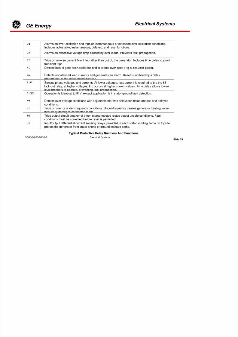
8/18/2019 71777896 - LM6000 Package Familiarization & Operations.pdf
http://slidepdf.com/reader/full/71777896-lm6000-package-familiarization-operationspdf 437/786
Electrical Systems
g GE Energy Electrical Systems
Slide 73F-000-00-60-000-00
To prevent unauthorized access, the M-3425 has three levels of access codes. Each access code is auser defined one- to four-digit number.
Target Indicators – Individual target LEDS illuminate when their respective relay functions areactivated. Once activated, they remain illuminated until the indicated fault condition is clearedand the RESET pushbutton on the 3425 front panel is depressed. Pressing and releasing the
TARGET RESET pushbutton will momentarily light all LEDS as a self-test feature.
Level 3 Access – Access to all M-3425 configuration functions and settings.M-3925 Target Module
Level 2 Access – Read and change set points, monitor status, view target history.
Level 1 Access – Read set points, monitor status, view target history.

8/18/2019 71777896 - LM6000 Package Familiarization & Operations.pdf
http://slidepdf.com/reader/full/71777896-lm6000-package-familiarization-operationspdf 438/786
Electrical Systems
g GE Energy Electrical Systems
Slide 74F-000-00-60-000-00
The mechanically latched 86 relay cannot be reset until its interconnected target/s are reset. Protectiverelay types have been assigned numbers that identify their functions in accordance with conventions andstandards established by the American Institute of Electronics and Electrical Engineers (AIEEE). Thefollowing table lists the most common protective relay types, their numbers, and a brief description of
their respective functions.
For information that is outside the scope of basic operational use, operators should consult themanufacturers instruction manual, Beckwith Electric Co., Inc., M-3425 Generator Protection InstructionBook .
Output Indicators – Eight programmable output contacts are provided to enable external functionssuch as alarms, lockout commands, status indications, etc. Individual LED indicators are provided atthe bottom of the target module to inform operators of the status of these contacts.
Detailed information about the cause of the last 32 relay operations are retained in the unit’s memoryfor access through the LCD display via the VIEW TARGET HISTORY menu.
The protective relay types furnished for each project and their interconnections are given on One LineDiagram XXX031 in the drawing section of this manual.

8/18/2019 71777896 - LM6000 Package Familiarization & Operations.pdf
http://slidepdf.com/reader/full/71777896-lm6000-package-familiarization-operationspdf 439/786
Electrical Systems
g GE Energy Electrical Systems
Slide 75F-000-00-60-000-00
24 Alarms on over-excitation and trips on instantaneous or extended over-excitation conditions.Includes adjustable, instantaneous, delayed, and reset functions.
27 Alarms on excessive voltage drop caused by over-loads. Prevents fault propagation.
32 Trips on reverse current flow into, rather than out of, the generator. Includes time delay to avoidtransient trips.
40 Detects loss of generator excitation and prevents over-speeding at reduced power.
46 Detects unbalanced load currents and generates an alarm. Reset is inhibited by a delay
proportional to the unbalanced duration.
51V Senses phase voltages and currents. At lower voltages, less current is required to trip the 86lock-out relay; at higher voltages, trip occurs at higher current values. Time delay allows lower-level breakers to operate, preventing fault propagation.
51GN Operation is identical to 51V, except application is in stator ground fault detection.
59 Detects over-voltage conditions with adjustable trip time delays for instantaneous and delayedconditions.
81 Trips on over or under-frequency conditions. Under-frequency causes generator heating; over-frequency damages connected loads.
86 Trips output circuit breaker of other interconnected relays detect unsafe conditions. Faultconditions must be corrected before reset is permitted.
87 Input/output differential current sensing relays, provided in each stator winding, force 86 trips toprotect the generator from stator shorts or ground leakage paths.
Typical Protective Relay Numbers And Functions

8/18/2019 71777896 - LM6000 Package Familiarization & Operations.pdf
http://slidepdf.com/reader/full/71777896-lm6000-package-familiarization-operationspdf 440/786
Electrical Systems
g GE Energy Electrical Systems
Slide 76F-000-00-60-000-00
CONTROL ROOM LAYOUT

8/18/2019 71777896 - LM6000 Package Familiarization & Operations.pdf
http://slidepdf.com/reader/full/71777896-lm6000-package-familiarization-operationspdf 441/786
Electrical Systems
g GE Energy Electrical Systems
Slide 77F-000-00-60-000-00
CONTROL ROOM LAYOUT
BATTERIES AND MOTOR CONTROL CENTER (MCC)
The skid mounted control room houses both the motor control center (MCC) and the three sets ofbatteries.
Battery System
Two 24-VDC battery systems supply backup power to the control systems and the firesuppression and gas detection system during nonscheduled power failures. The 125-VDCbattery system supplies backup power to the switchgear and MTTB cooler during nonscheduledpower failures.
Motor Control Center
The MCC distributes power to motors, pumps, heat exchangers, the air-oil separator, fans,the air compressor, heaters, and the 208/120V lighting-and-distribution panel.

8/18/2019 71777896 - LM6000 Package Familiarization & Operations.pdf
http://slidepdf.com/reader/full/71777896-lm6000-package-familiarization-operationspdf 442/786
Electrical Systems
g GE Energy Electrical Systems
Slide 78F-000-00-60-000-00
Typical Motor Control CenterTypical Circuit Breaker
MOTOR CONTROL CENTER
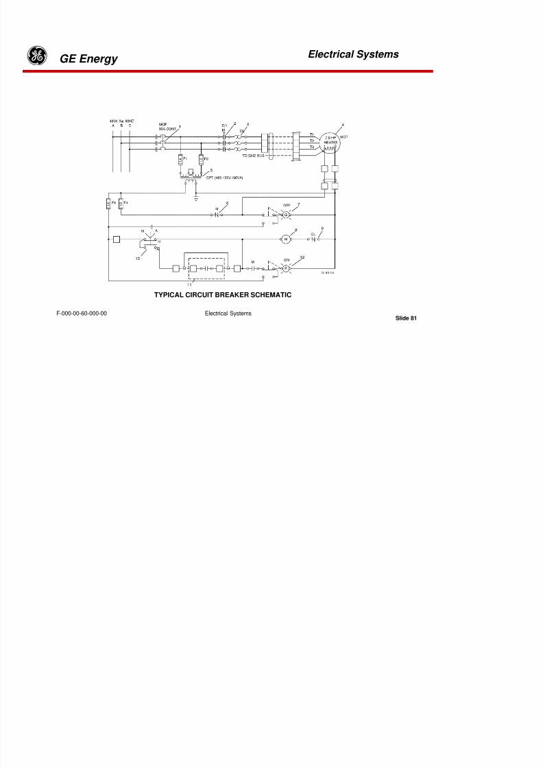
8/18/2019 71777896 - LM6000 Package Familiarization & Operations.pdf
http://slidepdf.com/reader/full/71777896-lm6000-package-familiarization-operationspdf 443/786
Electrical Systems
g GE Energy Electrical Systems
Slide 79F-000-00-60-000-00
MOTOR CONTROL CENTER
The motor control center (MCC) is a power distribution circuit breaker array that providesoverload protection and switching of power to devices such as motors and heaters. Theassembly also provides circuit breaker protection for lighting and distribution circuits.
Each circuit breaker is labeled on the front panel.
The individual high-current breaker panels contain a “starter,” in addition to a breaker.
The starter is a set of high-current–capacity contacts, capable of withstanding multipleON/OFF cycles without significant degradation. The starter contacts may be remotely orlocally controlled.
Primary 3-phase power enters through cables at the upper-left corner panel. Busbarconnections are routed from the primary 3--phase input cable connection lugs throughout the
cabinet. Individual circuit breaker assemblies plug into the busbars. Voltage outputs to loadsare carried through cables from each unit.
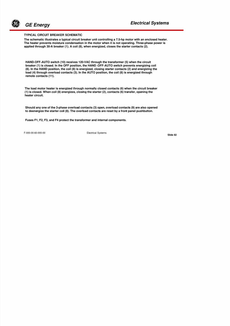
8/18/2019 71777896 - LM6000 Package Familiarization & Operations.pdf
http://slidepdf.com/reader/full/71777896-lm6000-package-familiarization-operationspdf 444/786
Electrical Systems
g GE Energy Electrical Systems
Slide 80F-000-00-60-000-00
The individual circuit breaker panels also contain an overload sensor, which opens the startercontacts to prevent overload conditions from damaging connected equipment.
Pressing the reset pushbutton resets the starter after a circuit overload has been corrected.
Selection of remote or local starter control is provided through the HAND-OFF-AUTO control switch.The red lamp is on when the starter is closed. The green lamp is on when the starter is open or off.These lamps have built-in pushbuttons for lamp test.
The overload sensor opens the starter at approximately 80% of the circuit breaker trip point, toavoid opening the circuit breaker except under the most severe overloads.
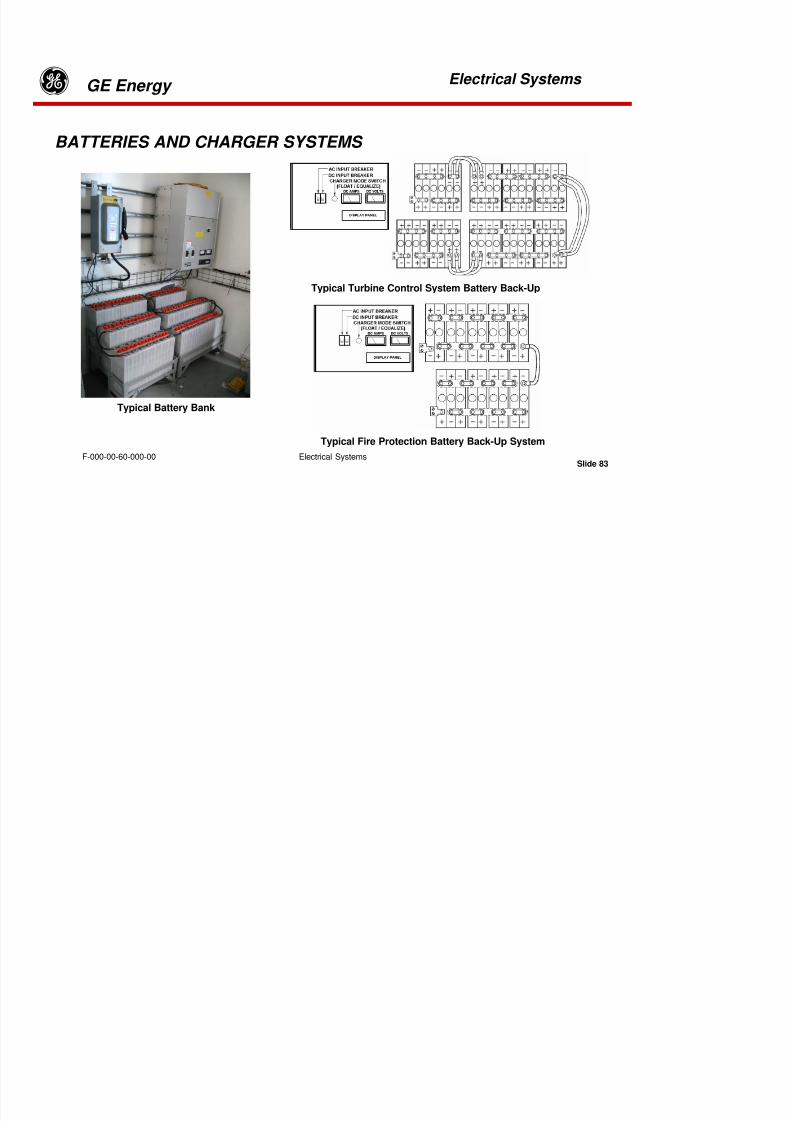
8/18/2019 71777896 - LM6000 Package Familiarization & Operations.pdf
http://slidepdf.com/reader/full/71777896-lm6000-package-familiarization-operationspdf 445/786
Electrical Systems
g GE Energy Electrical Systems
Slide 81F-000-00-60-000-00
TYPICAL CIRCUIT BREAKER SCHEMATIC

8/18/2019 71777896 - LM6000 Package Familiarization & Operations.pdf
http://slidepdf.com/reader/full/71777896-lm6000-package-familiarization-operationspdf 446/786
Electrical Systems
g GE Energy Electrical Systems
Slide 82F-000-00-60-000-00
TYPICAL CIRCUIT BREAKER SCHEMATIC
The schematic illustrates a typical circuit breaker unit controlling a 7.5-hp motor with an enclosed heater.The heater prevents moisture condensation in the motor when it is not operating. Three-phase power isapplied through 30-A breaker (1). A coil (8), when energized, closes the starter contacts (2).
Should any one of the 3-phase overload contacts (3) open, overload contacts (9) are also openedto deenergize the starter coil (8). The overload contacts are reset by a front panel pushbutton.
Fuses F1, F2, F3, and F4 protect the transformer and internal components.
The load motor heater is energized through normally closed contacts (6) when the circuit breaker(1) is closed. When coil (8) energizes, closing the starter (2), contacts (6) transfer, opening theheater circuit.
HAND-OFF-AUTO switch (10) receives 120-VAC through the transformer (5) when the circuitbreaker (1) is closed. In the OFF position, the HAND-OFF-AUTO switch prevents energizing coil(8). In the HAND position, the coil (8) is energized, closing starter contacts (2) and energizing theload (4) through overload contacts (3). In the AUTO position, the coil (8) is energized throughremote contacts (11).

8/18/2019 71777896 - LM6000 Package Familiarization & Operations.pdf
http://slidepdf.com/reader/full/71777896-lm6000-package-familiarization-operationspdf 447/786
Electrical Systems
g GE Energy Electrical Systems
Slide 83F-000-00-60-000-00
Typical Fire Protection Battery Back-Up System
Typical Turbine Control System Battery Back-Up
BATTERIES AND CHARGER SYSTEMS
Typical Battery Bank

8/18/2019 71777896 - LM6000 Package Familiarization & Operations.pdf
http://slidepdf.com/reader/full/71777896-lm6000-package-familiarization-operationspdf 448/786
Electrical Systems
g GE Energy Electrical Systems
Slide 84F-000-00-60-000-00
BATTERIES AND CHARGER SYSTEMS
Batteries and charger systems are furnished as uninterruptible power supplies for the computer controlsystem, its HMI, and the Fire Protection System. Safety requires these systems to remain in operation ifprimary power is lost.
Typical system configurations require 24 VDC and 125 VDC for the computer control system and aseparate 24 VDC power supply for the Fire Protection System. If a DC lube oil pump is provided, the125-VDC batteries are sized to accommodate both the pump and the turbine control system. Batteryconfigurations and interconnections can be confirmed on the system one-line drawing -XXX031.
g
8/18/2019 71777896 - LM6000 Package Familiarization & Operations.pdf
http://slidepdf.com/reader/full/71777896-lm6000-package-familiarization-operationspdf 449/786
Electrical Systems
g GE Energy Electrical Systems
Slide 85F-000-00-60-000-00
Temperature Compensation
Battery chargers manufactured by SENS Stored Energy Systems include in their part numberthe designation DCT for chargers supplied with battery temperature compensation (TC). Allbatteries for maximum performance and life require temperature compensation. The TC
feature automatically reduces the chargers output voltage at high temperatures, and raisesthe output voltage for low temperatures. The unit is configured at the factory for local sensingof battery temperature (i.e. at the cooling air intake of the charger).
The charger unit also includes, as standard, a provision for remote temperature sensing atthe battery location. If this is the case, the optional SENS remote temperature sensor (RTS)should be obtained from the manufacturer’s factory. When the optional remote sensor isattached correctly to the charger control board, the charger unit automatically selects theremote sensor. If the remote sensor becomes damaged or disconnected, temperaturesensing automatically reverts to local sensor.
g

8/18/2019 71777896 - LM6000 Package Familiarization & Operations.pdf
http://slidepdf.com/reader/full/71777896-lm6000-package-familiarization-operationspdf 450/786
Electrical Systems
g GE Energy Electrical Systems
Slide 86F-000-00-60-000-00
Start-up Procedures
1. Assure both input and output breakers are OFF.
2. Check that the connected battery voltage is correct (e.g. 120 volts for a 120-volt charger). It is OK if
the battery voltage is different from the nominal value by a few percent. If the battery voltage is morethan 10% different from the rated voltage of the charger, recheck the connections before turning on eitherbreaker.
3. Close the AC input breaker. Check that the voltage comes up to approximately 15% above nominal.(Some voltages overshoot on initial start-up is normal).
4. Close the DC output breaker. The charger will immediately begin to supply current if required bythe battery or load.
5. In chargers with alarms code “6”, the front panel AC FAIL and CHARGER FAIL lights will extinguishand the green AC ON light will illuminate.
6. The charger will automatically supply power to the load and maintain the battery without furtherattention. If the charger does not start as described, or appears to have failed, check the following:
g

8/18/2019 71777896 - LM6000 Package Familiarization & Operations.pdf
http://slidepdf.com/reader/full/71777896-lm6000-package-familiarization-operationspdf 451/786
Electrical Systems
g GE Energy Electrical Systems
Slide 87F-000-00-60-000-00
Verify AC power is available
Verify no external circuit breakers are tripped
Verify contractor-installed AC, DC and alarm connections are correctDisconnect AC and DC power sources. Open the charger and verify no components (e.g.main DC output fuse, if fitted) or harness connections are loose or damaged.
g

8/18/2019 71777896 - LM6000 Package Familiarization & Operations.pdf
http://slidepdf.com/reader/full/71777896-lm6000-package-familiarization-operationspdf 452/786
Electrical Systems
g GE Energy Electrical Systems
Slide 88F-000-00-60-000-00
Front Panel Controls
Three modes of charger operation are selectable using a three-position front panel selectorswitch. The modes are Float, Boost, or Auto.
The Auto mode selection enables the charger to determine the state of charge by measuringbattery charging current. If fast charging is required, the unit operates in Boost mode untilthe batteries are fully charged and the charging current drops below about 50% of thecharger’s rated current. When battery load demand increases to about 70% of the charger’srated output, the charger will resume operation in the Boost mode.
Boost mode selection places a higher voltage across the battery terminals, increasingthe charging current to equalize the voltage on all the connected batteries. Continued
operation in boost mode is not recommended because the high charging current cancause the battery electrolyte to boil away.
When Float mode is selected the battery charging current is set to the proper level tomaintain the battery in the fully charged state. Under normal conditions Float is therecommended mode for battery maintenance.
g

8/18/2019 71777896 - LM6000 Package Familiarization & Operations.pdf
http://slidepdf.com/reader/full/71777896-lm6000-package-familiarization-operationspdf 453/786
Electrical Systems
g GE Energy Electrical Systems
Slide 89F-000-00-60-000-00
Alarm Indications
Chargers are equipped with a “dead-front” panel. Alarm LEDs are behind the dead-front paneland will be visible when they illuminate due to an alarm condition, or when the test button ispressed. Chargers with no alarms have no LEDs or test buttons.
The alarm/display circuit monitors battery voltage and charger performance. The alarmcircuitry consists of eight separate circuits: AC Fail, Charge Fail, High DC, Low DC,Low Voltage, Load Disconnect, Ground Fault, Option, and Summary. Some of thealarm relays utilize time delays of approximately 25 seconds to eliminate the incidence
of spurious alarm indications.

8/18/2019 71777896 - LM6000 Package Familiarization & Operations.pdf
http://slidepdf.com/reader/full/71777896-lm6000-package-familiarization-operationspdf 454/786
Tab 14
8/18/2019 71777896 - LM6000 Package Familiarization & Operations.pdf
http://slidepdf.com/reader/full/71777896-lm6000-package-familiarization-operationspdf 455/786
50 HZ Generator Construction
Slide 1
GE EnergyGE EnergyGE EnergyGE Energy
F-000-00-30-100-01 50 HZ Generator Construction
50 HZ GENERATOR CONSTRUCTION

8/18/2019 71777896 - LM6000 Package Familiarization & Operations.pdf
http://slidepdf.com/reader/full/71777896-lm6000-package-familiarization-operationspdf 456/786
50 HZ Generator Construction
Slide 2
GE EnergyGE EnergyGE EnergyGE Energy
F-000-00-30-100-01 50 HZ Generator Construction
BRUSH GENERATOR
0 HZ G C i
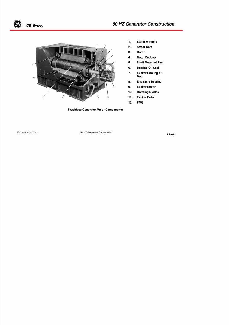
8/18/2019 71777896 - LM6000 Package Familiarization & Operations.pdf
http://slidepdf.com/reader/full/71777896-lm6000-package-familiarization-operationspdf 457/786
50 HZ Generator Construction
Slide 3
GE EnergyGE EnergyGE EnergyGE Energy
F-000-00-30-100-01 50 HZ Generator Construction
GENERATOR OVERVIEW
Electric power generators convert rotational shaft horsepower into electrical energy. Typical outputfrom electric generators furnished in GE Energy Products gas turbine-generator (GTG) packageswith LM6000 engines is 50 megawatts (MW) under ideal conditions. The LM6000 engine producesapproximately 55,000 shp. The limiting factor for production over 50 MW is the LM6000 engine. TheBrush generator is rated for 60.5 MW, 13.8 Kv. The generator is oversized to provide added safetymargins and provide for future power increasing enhancements developed for the engine.
The generator is installed in an isolated, pressurized enclosure to prevent explosive gas leakagefrom the engine into the generator compartment, where possible ignition could occur. It alsoprovides enclosed filtered air for cooling of the generator.
The unit is bolted to the gas turbine-generator package main skid, such that the rotor is axiallyaligned with the engine drive shaft. A flexible coupling through the engine intake connects the
generator rotor to the engine’s low pressure compressor (LPC) drive shaft.
50 HZ G t C t ti

8/18/2019 71777896 - LM6000 Package Familiarization & Operations.pdf
http://slidepdf.com/reader/full/71777896-lm6000-package-familiarization-operationspdf 458/786
50 HZ Generator Construction
Slide 4
GE EnergyGE EnergyGE EnergyGE Energy
F-000-00-30-100-01 50 HZ Generator Construction
The generator is characterized as a three-phase, two-pole brushless excitertype, with an open-circuit air-cooling system. To avoid degraded
performance under high-current loads or ambient temperatures, coolinghas been a major consideration in the design of the generator.
Bearings at the drive and non-drive ends support the 12-ton rotor. Thegross weight of the assembled generator is approximately 92 tons.
50 HZ Generator Constr ction

8/18/2019 71777896 - LM6000 Package Familiarization & Operations.pdf
http://slidepdf.com/reader/full/71777896-lm6000-package-familiarization-operationspdf 459/786
50 HZ Generator Construction
Slide 5
GE EnergyGE EnergyGE EnergyGE Energy
F-000-00-30-100-01 50 HZ Generator Construction
1. Stator Winding
2. Stator Core
3. Rotor
4. Rotor Endcap
5. Shaft Mounted Fan
6. Bearing Oil Seal
7. Exciter Cooling AirDuct
8. Endframe Bearing
9. Exciter Stator
10. Rotating Diodes
11. Exciter Rotor
12. PMG
Brushless Generator Major Components
50 HZ Generator Construction
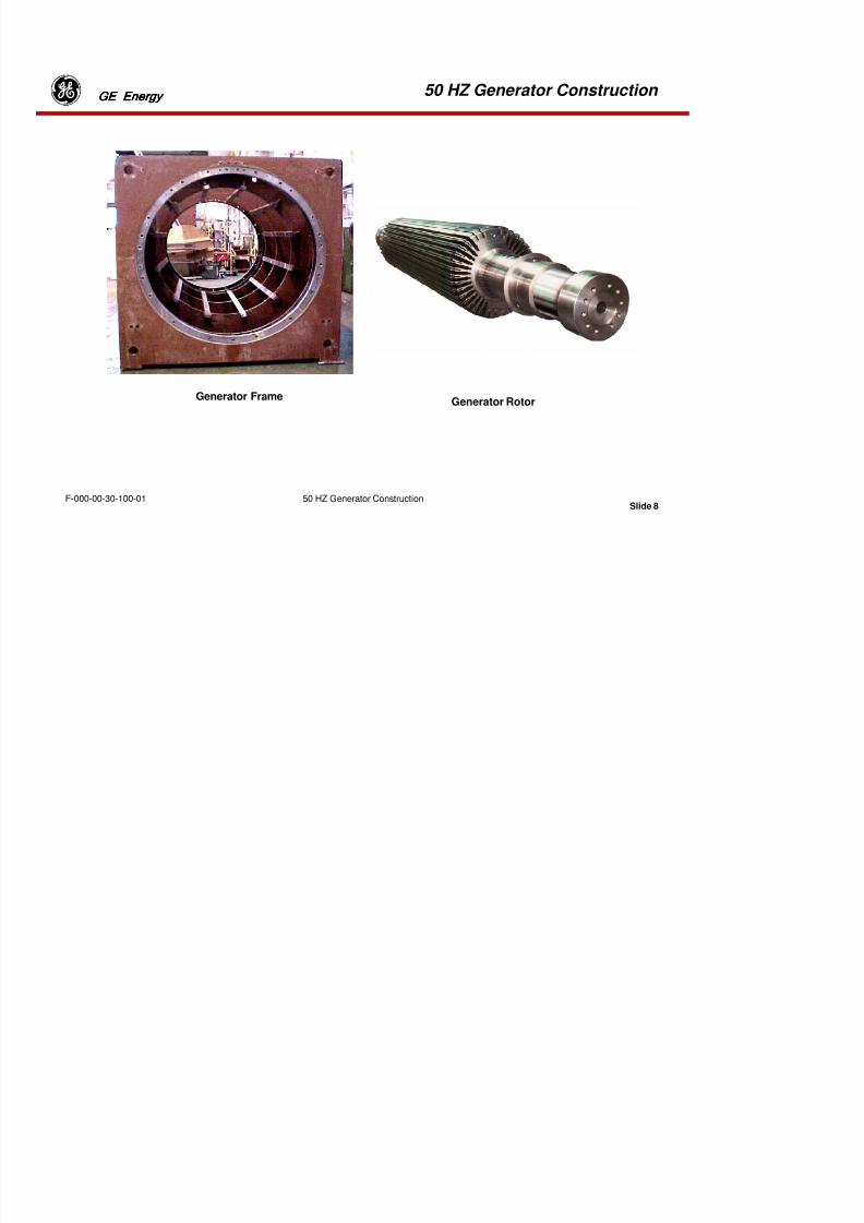
8/18/2019 71777896 - LM6000 Package Familiarization & Operations.pdf
http://slidepdf.com/reader/full/71777896-lm6000-package-familiarization-operationspdf 460/786
50 HZ Generator Construction
Slide 6
GE EnergyGE EnergyGE EnergyGE Energy
F-000-00-30-100-01 50 HZ Generator Construction
MAJOR COMPONENTS
1. Stator Winding - High voltage coils are mounted in the generator frame. Rotor’s lines
of force cut through these coils and create the generator’s output voltage.
2. Stator Core – Thin laminations of low-loss electrical steel are stacked together to formthe generator core. The core concentrates the rotor’s magnetic flux in the stator coils andcompletes the path of the rotor’s magnetic loops.
3. Rotor – The rotor is a 12-ton, solid forging of nickel-chromium-molybdenum alloysteel. The rotor supports the field windings of solid copper bars. Current in the rotorwindings creates magnetic flux around the rotor. This flux cuts the stator coils andproduces the generator’s high-voltage output.
4. Rotor Endcaps – The rotor endcaps are non-magnetic steel. The endcaps cover andprotect the end portions of the rotor windings.
5. Shaft-Mounted Fan(s) – Two fans (one on each end of the rotor) pull cooling air intothe generator through top inlets at each end of the generator frame. The fans force the airover the rotor and core and out through the central top exhaust exit.
50 HZ Generator Construction
8/18/2019 71777896 - LM6000 Package Familiarization & Operations.pdf
http://slidepdf.com/reader/full/71777896-lm6000-package-familiarization-operationspdf 461/786
50 HZ Generator Construction
Slide 7
GE EnergyGE EnergyGE EnergyGE Energy
F-000-00-30-100-01 50 HZ Generator Construction
6. Pressure Oil Seals – Twin lube oil seals are mounted at the inner and outer edge of each bearingcavity. Air pressure from the shaft fans is inserted between the seals to contain the bearing lubeoil.
7. Exciter Cooling Air Duct – A fan on the exciter shaft pulls cooling air through this duct and forcesthe air over the exciter components.
8. Endframe Bearing(s) – White-metal lined, hydrodynamic, cylindrical bearings support the rotorshaft at each end. These bearings require continuous lubrication while the rotor is turning.
9. Exciter Stator – DC excitation current flows through these fixed stator coils, producing a magneticfield around the coils. The exciter rotor coils cut through this magnetic field, and a voltage is
built in the rotating coils. Note: The energy is transferred to the rotating shaft without brushes,slip rings or physical contact.
10. Rotating Diodes – These diodes rectify the AC voltage in the Exciter Rotor Coils and produce DCcurrent to energize the rotor main windings.
11. Exciter Rotor – A voltage is built in the Exciter Rotor coils when they cut through the magnetic fluxof the Exciter Stator coils. This voltage is rectified by diodes, providing DC current to energizethe main rotor windings.
12. Permanent Magnet Generator (PMG) – The flux from sixteen shaft-mounted permanent magnetscuts through the PMG stator coils and creates the AC utility voltage needed for excitation.
50 HZ Generator Construction
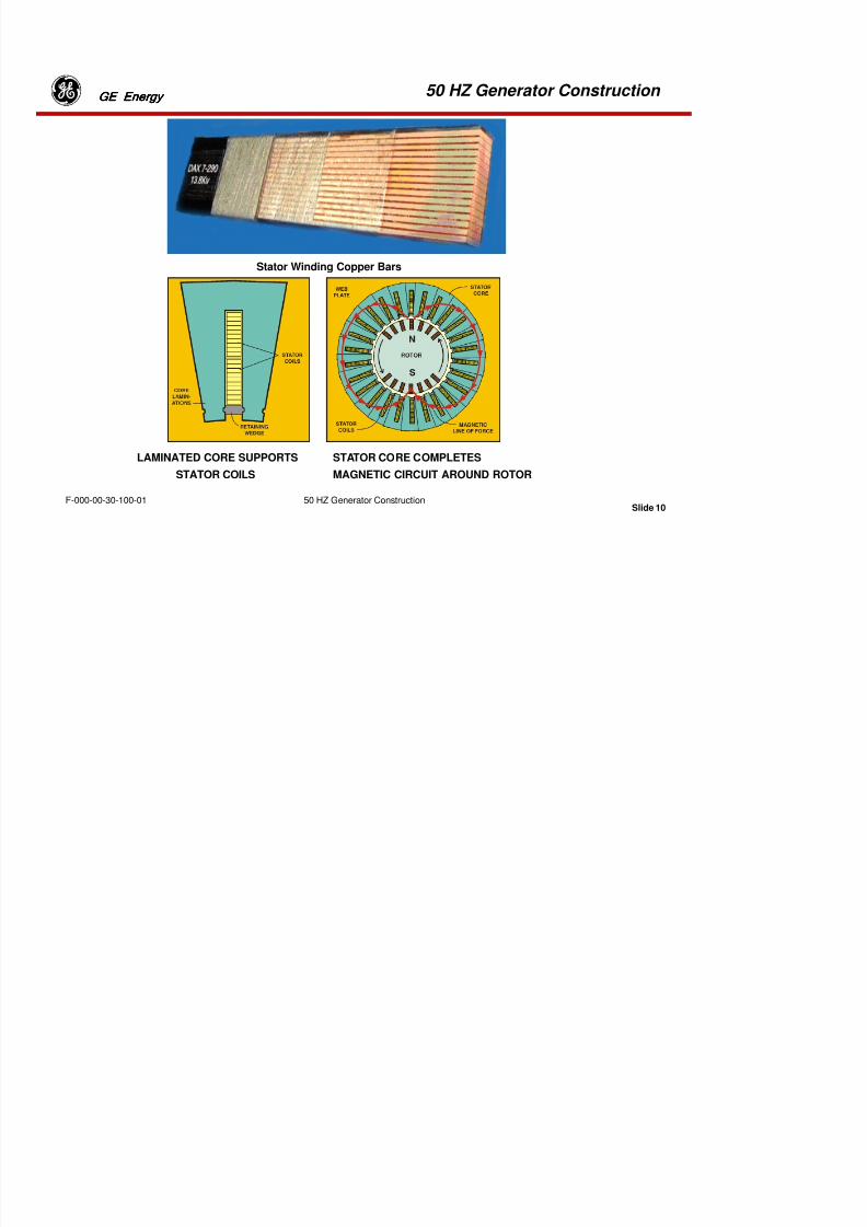
8/18/2019 71777896 - LM6000 Package Familiarization & Operations.pdf
http://slidepdf.com/reader/full/71777896-lm6000-package-familiarization-operationspdf 462/786
50 HZ Generator Construction
Slide 8
GE EnergyGE EnergyGE EnergyGE Energy
F-000-00-30-100-01 50 HZ Generator Construction
Generator Frame
Generator Rotor
50 HZ Generator ConstructionGE EGE EGE EGE E

8/18/2019 71777896 - LM6000 Package Familiarization & Operations.pdf
http://slidepdf.com/reader/full/71777896-lm6000-package-familiarization-operationspdf 463/786
50 HZ Generator Construction
Slide 9
GE EnergyGE EnergyGE EnergyGE Energy
F-000-00-30-100-01 50 HZ Generator Construction
Generator Frame
The generator frame is a box-shaped weldment built of carbon steel plates. The frame isstiffened internally by web plates. These plates are aligned by “key bars” running parallel to theaxis of the machine. The key bars support the stator core.
After fabrication, the generator frame is machined on a large lathe. The lathe cuts an accuratecylinder along the axis and provides machined faces on each end for mounting the generatorend pieces.
Main Rotor
The rotor is machined from a single alloy-steel forging of tested metallurgical properties.Longitudinal slots are machined radially in the body in which the rotor windings are installed.
The windings are secured against centrifugal force by steel wedges fitted into dovetail openingsmachined in the rotor slots. The coils are insulated from the slot walls by molded slot liners.Molded ring insulation is provided at the coil ends to separate and support the coils underthermal and rotational stresses. A centering ring held into place by shrink fit restricts axialmovement.
A single brush, spring-loaded against the rotor, carries stray ground currents from the rotor to
the frame ground. The brush is located near the drive end of the main rotor.
50 HZ Generator ConstructionGE EGE EGE EGE E
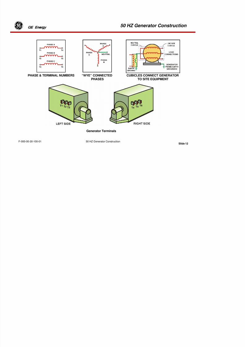
8/18/2019 71777896 - LM6000 Package Familiarization & Operations.pdf
http://slidepdf.com/reader/full/71777896-lm6000-package-familiarization-operationspdf 464/786
50 HZ Generator Construction
Slide 10
GE EnergyGE EnergyGE EnergyGE Energy
F-000-00-30-100-01 50 HZ Generator Construction
Stator Winding Copper Bars
LAMINATED CORE SUPPORTS
STATOR COILS
STATOR CORE COMPLETES
MAGNETIC CIRCUIT AROUND ROTOR
50 HZ Generator ConstructionGE EnergyGE EnergyGE EnergyGE Energy

8/18/2019 71777896 - LM6000 Package Familiarization & Operations.pdf
http://slidepdf.com/reader/full/71777896-lm6000-package-familiarization-operationspdf 465/786
50 HZ Generator Construction
Slide 11
GE EnergyGE EnergyGE EnergyGE Energy
F-000-00-30-100-01 50 HZ Generator Construction
Stator Core
The stator core is built into a fabricated steel frame and consists of low-loss silicon, steel-segmented stampings insulated by a layer of varnish on both sides. The stampings aredivided into short sections by radial-ventilating ducts
extending from the center through to the outer ends. The stator windings are arranged inpatterns to minimize circulating currents. Conducting tape between the windings and themachine frame provides Corona protection.
The stator core is a compressed stack of insulated, laminated steel strips. (The laminatedconstruction reduces electrical losses in the core.) The stator core provides the “returnpath” to complete the rotor’s magnetic circuit. This concentrates the flux and producesmore power in the stator coils.
50 HZ Generator Construction GE EnergyGE EnergyGE EnergyGE Energy
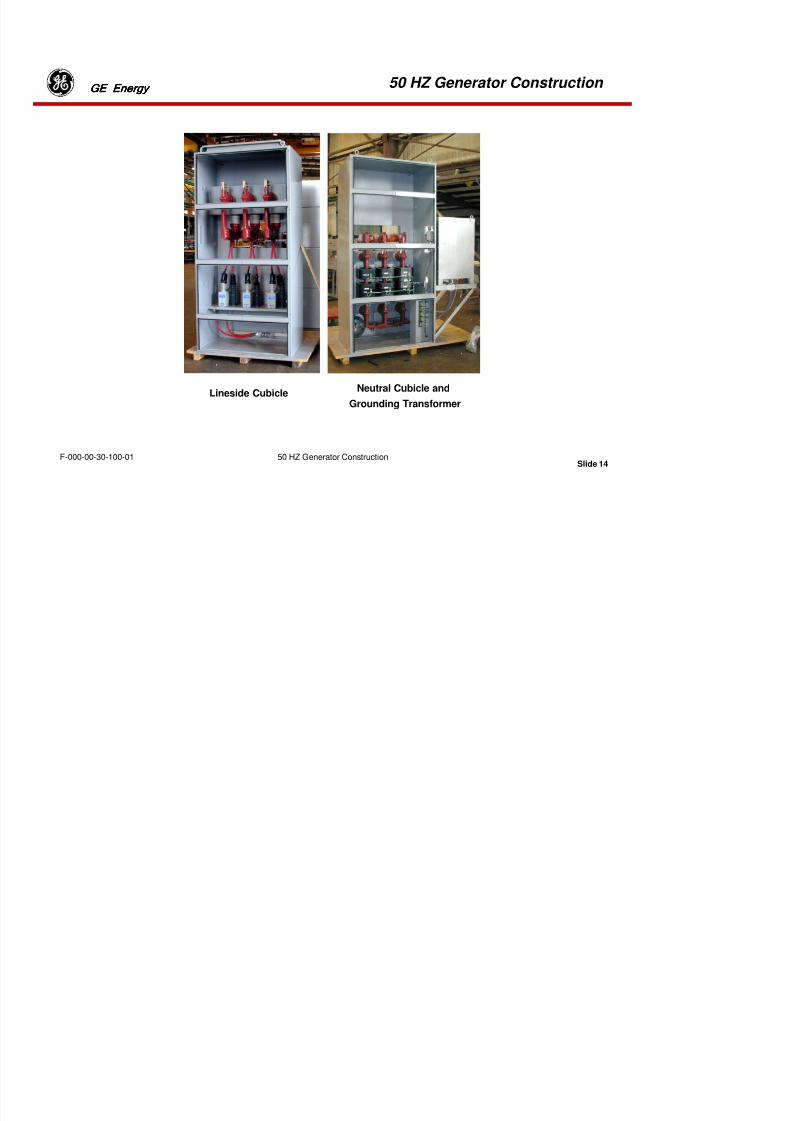
8/18/2019 71777896 - LM6000 Package Familiarization & Operations.pdf
http://slidepdf.com/reader/full/71777896-lm6000-package-familiarization-operationspdf 466/786
Slide 12
GE EnergyGE EnergyGE EnergyGE Energy
F-000-00-30-100-01 50 HZ Generator Construction
Generator Terminals
CUBICLES CONNECT GENERATORTO SITE EQUIPMENT
“WYE” CONNECTEDPHASES
PHASE & TERMINAL NUMBERS
50 HZ Generator Construction GE EnergyGE EnergyGE EnergyGE Energy

8/18/2019 71777896 - LM6000 Package Familiarization & Operations.pdf
http://slidepdf.com/reader/full/71777896-lm6000-package-familiarization-operationspdf 467/786
Slide 13
GE EnergyGE EnergyGE EnergyGE Energy
F-000-00-30-100-01 50 HZ Generator Construction
Generator Connections
The generator has three stator coils, one per phase. Standard phase and terminal numbering isshown in “A” above. Three coil terminals extend through the left side of the generator
housing, near the exciter end of the frame (T1,T2,T3), and three terminals extend through theright side of the generator housing (T4,T5,T6), as shown below.
The generator connects to the site equipment through Lineside and Neutral Cubicles. Thesecubicles contain heavy busbars to transmit the generator voltage to the load. The cubicles aremounted on the outside of the generator enclosure at the site. The Lineside Cubicle can bemounted on either side of the generator enclosure - to suit the customer’s layout. The Neutral
Cubicle mounts on the side opposite from the Lineside Cubicle.
In the Neutral Cubicle, three of the generator terminals are connected together by busbar,creating a Wye arrangement, as shown in “B” above. The common, or “Neutral”, point isconnected to ground through a grounding transformer, as shown in “C” above.
50 HZ Generator Construction GE EnergyGE EnergyGE EnergyGE Energy
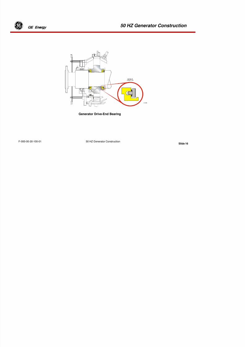
8/18/2019 71777896 - LM6000 Package Familiarization & Operations.pdf
http://slidepdf.com/reader/full/71777896-lm6000-package-familiarization-operationspdf 468/786
Slide 14
GE EnergyGE EnergyGE EnergyGE Energy
F-000-00-30-100-01 50 HZ Generator Construction
Lineside CubicleNeutral Cubicle and
Grounding Transformer
50 HZ Generator Construction GE EnergyGE EnergyGE EnergyGE Energy

8/18/2019 71777896 - LM6000 Package Familiarization & Operations.pdf
http://slidepdf.com/reader/full/71777896-lm6000-package-familiarization-operationspdf 469/786
Slide 15
gygygygy
F-000-00-30-100-01 50 HZ Generator Construction
Lineside Cubicle
The Lineside cubicle connects to the high-voltage output terminals of the generator. The customer then connectsthe Lineside cubicle to the generator circuit breaker (52G) with busbar or high voltage cables.
Three sets of lightning arrestors and surge capacitors are mounted in the Lineside cubicle. These devices “short-circuit” lightning energy to ground and protect the generator if lightning should strike the grid.
Neutral Cubicle
The Neutral cubicle connects to the side of the enclosure opposite the Lineside cubicle. Busbars in the Neutralcubicle connect three phases together to form the “neutral point” of the generator Wye connection. The neutralpoint connects to earth ground through the Neutral Grounding Transformer. The Neutral cubicle also contains
three sets of current transformers. These transformers tell the control system how much current is flowing in eachof the three phases of the generator. The control system uses these 0-5 Amp signals for metering and relaying.
Neutral Grounding Transformer
The Neutral Grounding Transformer connects the neutral point of the generator’s Wye connection to ground.Grounding generators in this fashion provides a “common potential reference” for all the generators connected toa grid. This allows them to work smoothly in parallel. The Neutral Grounding Transformer also limits the maximum
current flow from ground back into the generator if a “phase conductor” should accidentally fall to earth orbecome grounded
50 HZ Generator Construction GE EnergyGE EnergyGE EnergyGE Energy

8/18/2019 71777896 - LM6000 Package Familiarization & Operations.pdf
http://slidepdf.com/reader/full/71777896-lm6000-package-familiarization-operationspdf 470/786
Slide 16
gygygygy
F-000-00-30-100-01 50 HZ Generator Construction
Generator Drive-End Bearing
50 HZ Generator Construction GE EnergyGE EnergyGE EnergyGE Energy
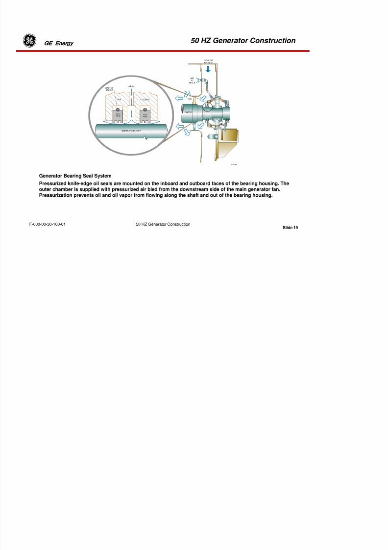
8/18/2019 71777896 - LM6000 Package Familiarization & Operations.pdf
http://slidepdf.com/reader/full/71777896-lm6000-package-familiarization-operationspdf 471/786
Slide 17F-000-00-30-100-01 50 HZ Generator Construction
Generator Drive-End Bearing
A pressure-lubricated journal bearing supports the rotor at the drive and non-drive ends. Thrust pads areinstalled between the drive-end journal and the bearing, to prevent longitudinal loads that may beimposed upon the drive turbine.
The bearings are supported in fabricated steel housings, which are bolted directly to the machine ends.The bearing housings are split on the horizontal shaft centerline with the lower half forming the bearingoil sump. The bearings are of plain cylindrical design, white metal lines, and spherically seated within theend frames. Oil under pressure is fed to the bearings and distributed over the bearing surface by internalgrooves.
50 HZ Generator Construction GE EnergyGE EnergyGE EnergyGE Energy
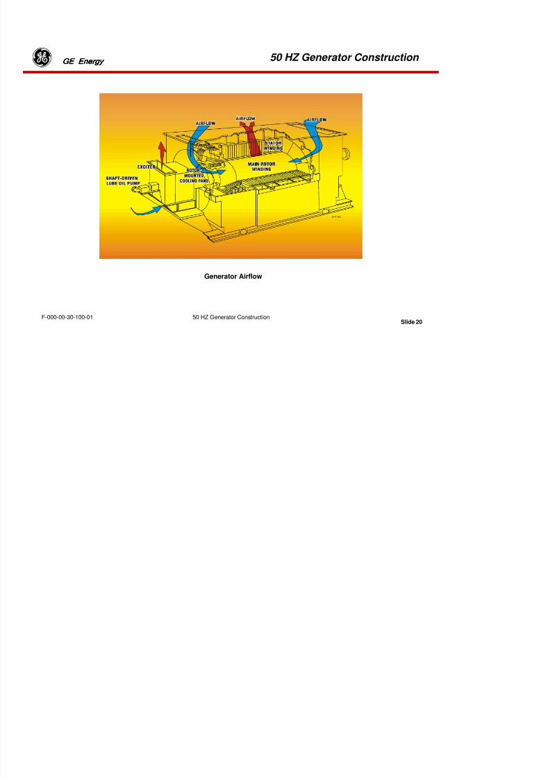
8/18/2019 71777896 - LM6000 Package Familiarization & Operations.pdf
http://slidepdf.com/reader/full/71777896-lm6000-package-familiarization-operationspdf 472/786
Slide 18F-000-00-30-100-01 50 HZ Generator Construction
GENERATOR BEARING LUBRICATION
On the 60Hz Generators, there are two Lube Oil Pumps. One is a Mechanically driven Pump attached to
the Generator Exciter end. And an Auxiliary AC Pump mounted in the lower portion of the Generatorenclosure.
On the 50Hz Generators, there are two AC Lube Oil Pumps (one is primary and the other Secondary) andone Auxiliary DC Lube Oil Pump.
On both the 50 and 60Hz Generators there are four “Rundown” tanks. Two on the Drive end and two onthe Non Drive End. Each tank contains 20 Gallons of Lube Oil and provide emergency bearing lubricationin case of Lube oil pump failure.
A “jacking” lube oil pump is provided to reduce breakaway torque during startup, crank cycles and off-line water wash motoring.
An orifice in the supply lines controls the bearing oil flow. Drain oil discharges into the bottom of thebearing housing from where it is returned to the lube oil system.
50 HZ Generator Construction GE EnergyGE EnergyGE EnergyGE Energy

8/18/2019 71777896 - LM6000 Package Familiarization & Operations.pdf
http://slidepdf.com/reader/full/71777896-lm6000-package-familiarization-operationspdf 473/786
Slide 19F-000-00-30-100-01 50 HZ Generator Construction
Generator Bearing Seal System
Pressurized knife-edge oil seals are mounted on the inboard and outboard faces of the bearing housing. Theouter chamber is supplied with pressurized air bled from the downstream side of the main generator fan.Pressurization prevents oil and oil vapor from flowing along the shaft and out of the bearing housing.
50 HZ Generator Construction GE EnergyGE EnergyGE EnergyGE Energy
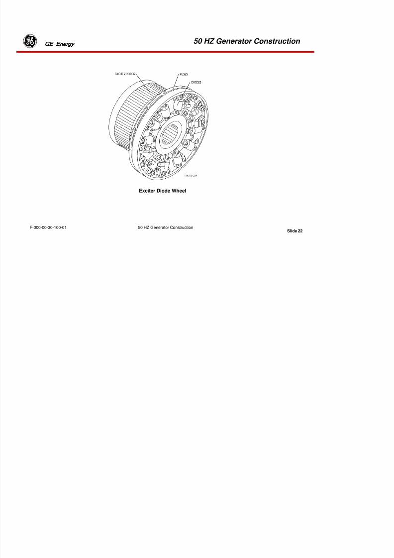
8/18/2019 71777896 - LM6000 Package Familiarization & Operations.pdf
http://slidepdf.com/reader/full/71777896-lm6000-package-familiarization-operationspdf 474/786
Slide 20F-000-00-30-100-01 50 HZ Generator Construction
Generator Airflow
50 HZ Generator Construction GE EnergyGE EnergyGE EnergyGE Energy

8/18/2019 71777896 - LM6000 Package Familiarization & Operations.pdf
http://slidepdf.com/reader/full/71777896-lm6000-package-familiarization-operationspdf 475/786
Slide 21
F-000-00-30-100-01 50 HZ Generator Construction
Generator Temperature Monitoring
Instrumentation installed within the generator by the generator manufacturer is as follows:•Three resistance temperature detectors (RTD's) are embedded in each stator winding—one ineach winding is a spare.
• Four RTD's are installed in the air duct flow path—two are operational, two are spares (onwater cooled generators they are used to monitor water temperatures).
•Two RTD’s are embedded in the bearings, one on the generator drive end and one on theexciter end.
•Two RTD’s are installed in the bearings oil supply drain flow, one on the generator drive endand one on the exciter end.
50 HZ Generator Construction GE EnergyGE EnergyGE EnergyGE Energy

8/18/2019 71777896 - LM6000 Package Familiarization & Operations.pdf
http://slidepdf.com/reader/full/71777896-lm6000-package-familiarization-operationspdf 476/786
Slide 22
F-000-00-30-100-01 50 HZ Generator Construction
Exciter Diode Wheel
50 HZ Generator Construction GE EnergyGE EnergyGE EnergyGE Energy

8/18/2019 71777896 - LM6000 Package Familiarization & Operations.pdf
http://slidepdf.com/reader/full/71777896-lm6000-package-familiarization-operationspdf 477/786
Slide 23
F-000-00-30-100-01 50 HZ Generator Construction
Exciter and Diode Assembly
The exciter assembly consists of a permanent magnet generator (PMG), an exciter stator and rotor, and arotating diode rectifier. These components are installed at the non-drive end of the generator shaft.
The PMG stator consists of a single-phase winding in a laminated core. Twelve permanent magnets rotateon the rotor inside the stator. The PMG output AC voltage is rectified and regulated by the modularautomatic voltage regulator (MAVR).
The exciter stator, which receives the MAVR output DC voltage, is mounted around the exciter rotor. Itconsists of a stationary ring that supports the stator poles and carries the magnetic flux between adjacentpoles. Stator windings are series-wound around laminated poles.
The exciter rotor is constructed from punched laminations and contains resin- impregnated, form-wound,and three-phase windings. A rotating diode assembly rectifies the AC voltage induced into the exciter rotor.
50 HZ Generator Construction GE EnergyGE EnergyGE EnergyGE Energy

8/18/2019 71777896 - LM6000 Package Familiarization & Operations.pdf
http://slidepdf.com/reader/full/71777896-lm6000-package-familiarization-operationspdf 478/786
Slide 24
F-000-00-30-100-01 50 HZ Generator Construction
Exciter Diode Wiring
The rectifier is a three-phase, full-wave bridge rectifier with parallel, individually fused diodes. The fusesare mounted on the reverse side of the diode assembly.
The redundant diode configuration enables the exciter to carry full generator output with as many as half
the diodes out of service. Because diodes have only two failure modes (shorted or open), the fuses provideover current protection and allow continued normal operation, unless two fuses open in any one of the sixrectifier legs.
A radio transmitter, powered by the rectifier DC voltage output, discontinues transmission, should a rotorground fault occur. A stationary radio receiver generates an alarm, should the transmitter signal cease.
Diode failure detection is accomplished by sensing ripple induced into the exciter field caused by theunbalanced load.
50 HZ Generator Construction GE EnergyGE EnergyGE EnergyGE Energy

8/18/2019 71777896 - LM6000 Package Familiarization & Operations.pdf
http://slidepdf.com/reader/full/71777896-lm6000-package-familiarization-operationspdf 479/786
Slide 25
F-000-00-30-100-01 50 HZ Generator Construction
Diode Failure Detection
Twelve diodes, each with a fuse in series, are mounted in parallel pairs in a three-phase bridge. Six of thediodes has positive bases and are mounted on one heat sink, the remaining six have negative bases andare mounted on the other heat sink.
The risk of diode failure is very remote. However, if a diode does break down a heavy reverse current willflow which is interrupted by the fuse. The adjacent diode and fuse would then be called upon to carry thewhole current that was previously divided between two parallel paths. Each path is designed withsufficient surplus capacity to carry the full current continuously. The generator will therefore continuerunning as if nothing had happen.
50 HZ Generator Construction GE EnergyGE EnergyGE EnergyGE Energy
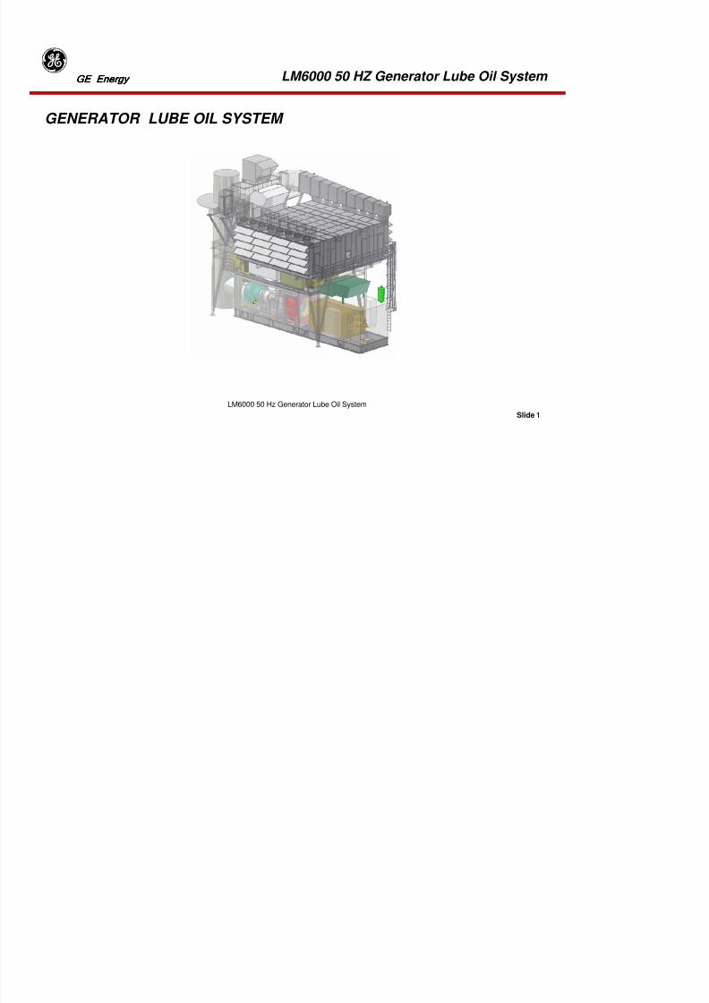
8/18/2019 71777896 - LM6000 Package Familiarization & Operations.pdf
http://slidepdf.com/reader/full/71777896-lm6000-package-familiarization-operationspdf 480/786
Slide 26
F-000-00-30-100-01 50 HZ Generator Construction
50Hz Gearbox AssemblyFor 50Hz applications, the 3600 rpm outputspeed of the LPT must be reduced to 3000rpm. This is done via a reduction Gearboxattached to the LPT output shaft and the
Generator Drive End.
The Gearbox consists of a turning gear motor, an input shaft and an output shaft.
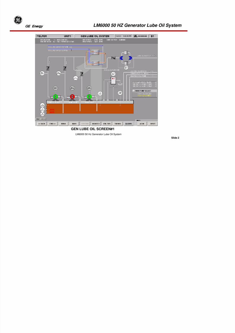
8/18/2019 71777896 - LM6000 Package Familiarization & Operations.pdf
http://slidepdf.com/reader/full/71777896-lm6000-package-familiarization-operationspdf 481/786
Tab 15
LM6000 50 HZ Generator Lube Oil System GE EnergyGE EnergyGE EnergyGE Energy

8/18/2019 71777896 - LM6000 Package Familiarization & Operations.pdf
http://slidepdf.com/reader/full/71777896-lm6000-package-familiarization-operationspdf 482/786
Slide 1
LM6000 50 Hz Generator Lube Oil System
GENERATOR LUBE OIL SYSTEM
LM6000 50 HZ Generator Lube Oil System GE EnergyGE EnergyGE EnergyGE Energy
8/18/2019 71777896 - LM6000 Package Familiarization & Operations.pdf
http://slidepdf.com/reader/full/71777896-lm6000-package-familiarization-operationspdf 483/786
Slide 2
LM6000 50 Hz Generator Lube Oil System
GEN LUBE OIL SCREEN#1
LM6000 50 HZ Generator Lube Oil System GE EnergyGE EnergyGE EnergyGE Energy

8/18/2019 71777896 - LM6000 Package Familiarization & Operations.pdf
http://slidepdf.com/reader/full/71777896-lm6000-package-familiarization-operationspdf 484/786
Slide 3
LM6000 50 Hz Generator Lube Oil System
GENERATOR LUBE OIL SCREEN#2
LM6000 50 HZ Generator Lube Oil System GE EnergyGE EnergyGE EnergyGE Energy
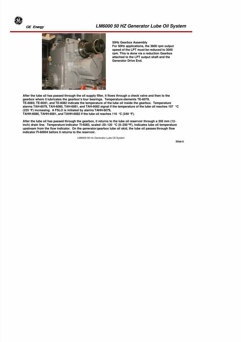
8/18/2019 71777896 - LM6000 Package Familiarization & Operations.pdf
http://slidepdf.com/reader/full/71777896-lm6000-package-familiarization-operationspdf 485/786
Slide 4
LM6000 50 Hz Generator Lube Oil System
System Overview
The generator lube oil system uses mineral lube oil to lubricate, cool and cleans the gearbox andgenerator bearings. In addition, the mineral oil is used to lift the generator rotor shaft for easier“break-away.” The generator lube oil system has two distinct subsystems: a pressurized supplysystem and a separate jacking oil system, which lifts and centers the generator rotor for starting.Each subsystem has its own filters.
The supply system has three pumps: one D/C motor driven supply oil pump and two A/C motordriven pump. A Single A/C motor-driven pump provides lubricating oil during operation. In case ofpump failure, when the header pressure drops to 20 psig (138 kPaG) the standby A/C pump comesonline. If pressure continues to drop to 12 psi (82 kPaG), the D/C motor driven pump will start toprovide oil to the system. In the event of a complete electrical or mechanical system failure, four 20gal (76 L) rundown tanks are provided to gravity feed oil to the bearings on both the generator and
gearbox. (2 per unit)
The jacking oil pump is used during startup and provides high-pressure oil to the rotor shaft to “lift”the shaft up on a cushion of oil so “break-away” is easier. The system also contains the following: areservoir, lube oil coolers, piping, valves, and instrumentation.
LM6000 50 HZ Generator Lube Oil System GE EnergyGE EnergyGE EnergyGE Energy

8/18/2019 71777896 - LM6000 Package Familiarization & Operations.pdf
http://slidepdf.com/reader/full/71777896-lm6000-package-familiarization-operationspdf 486/786
Slide 5
LM6000 50 Hz Generator Lube Oil System
Generator Supply Oil SystemThe generator A/C and D/C motor drivensupply pumps are located on the top of thelube oil reservoir. The supply pumps takesuction from the 3000-gallon (11356 liter)
stainless steel generator lube oil reservoir(mounted on the generator lube oil skid).
Discharge pressure from the supply element is regulated to 30 psi (206 kPaG) by apressure control valve and then piped to the supply lube oil cooler. From the supplylube oil cooler, the lube oil is piped to the supply oil duplex filters (rated at six (6)microns). From the filters, the lube oil goes to the lube oil header, to the rundowntanks, and to the bearings on both the gearbox and generator. The lube oil is thenreturned to the generator lube oil reservoir by return oil piping.

8/18/2019 71777896 - LM6000 Package Familiarization & Operations.pdf
http://slidepdf.com/reader/full/71777896-lm6000-package-familiarization-operationspdf 487/786
LM6000 50 HZ Generator Lube Oil System GE EnergyGE EnergyGE EnergyGE Energy

8/18/2019 71777896 - LM6000 Package Familiarization & Operations.pdf
http://slidepdf.com/reader/full/71777896-lm6000-package-familiarization-operationspdf 488/786
Slide 7
LM6000 50 Hz Generator Lube Oil System
GENERATOR JACKING OIL SYSTEMThe generator jacking oil system centers the generator (axially) and “lifts” the generator rotor on a high-pressure layer of oil for easier “break-away.” The jacking oil pump is a four (4)-element pump, two (2)high-pressure elements rated at 2850 psig (19,650 kPag), and two (2) low-pressure elements rated at 800psig (5516 kPag). Each pump element has a separate simplex discharge filter. The jacking oil pump
takes suction from the generator lube oil supply header. The HP oil is supplied to each side of thethrust bearing to axially center the rotor shaft. The LP oil is supplied to each journal bearing to “lift” therotor shaft up on a cushion of oil. This eliminates friction between the shaft and the bottom half of thejournal bearing making “break-away” easier.
LM6000 50 HZ Generator Lube Oil System GE EnergyGE EnergyGE EnergyGE Energy

8/18/2019 71777896 - LM6000 Package Familiarization & Operations.pdf
http://slidepdf.com/reader/full/71777896-lm6000-package-familiarization-operationspdf 489/786
Slide 8
LM6000 50 Hz Generator Lube Oil System
COMPONENT DESCRIPTION
A/C Motor Driven Lube Oil Pump
The A/C supply pumps are used to supply
pressurized oil to the generator supply oilsystem.The motor driven pump is rated at 330 gpm(1249 L/min). The pump motor is rated 25 hp(18.6 kw), 400 VAC, 3-phase, 50Hz, 1500 rpm.
D/C Motor Driven Lube Oil PumpThe D/C motor-driven pump is used to supply
oil to the generator supply oil system in caseof A/C pump failure.The motor driven pump is rated at 165 gpm(625 L/min). The motor for the pump is rated15 hp (11.1 kw), 125 VDC, 1500 rpm.
LM6000 50 HZ Generator Lube Oil System GE EnergyGE EnergyGE EnergyGE Energy
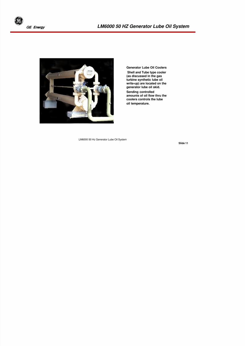
8/18/2019 71777896 - LM6000 Package Familiarization & Operations.pdf
http://slidepdf.com/reader/full/71777896-lm6000-package-familiarization-operationspdf 490/786
Slide 9
LM6000 50 Hz Generator Lube Oil System
A/C Motor Driven Pump Relief Valve
On the discharge side of the motor driven lube oil pumps are relief valves to protect the systemfrom over-pressurization. The valve relieves back to the reservoir and is set to open at 85 psig (586kPag).
D/C Motor Driven Pump Relief Valve
On the discharge side of the D/C motor driven lube oil pump is a relief valve to protect the systemfrom over-pressurizsion. The valve relieves back to the reservoir and is set to open at 30 psig (207kPag).
LM6000 50 HZ Generator Lube Oil System GE EnergyGE EnergyGE EnergyGE Energy
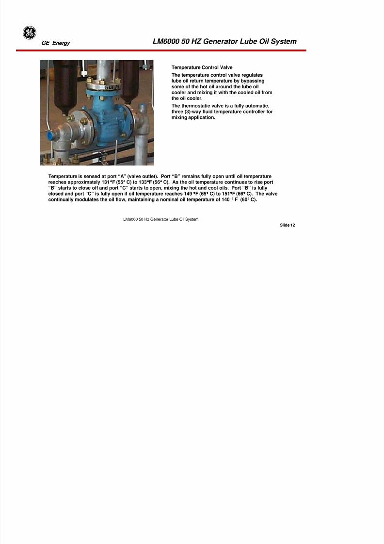
8/18/2019 71777896 - LM6000 Package Familiarization & Operations.pdf
http://slidepdf.com/reader/full/71777896-lm6000-package-familiarization-operationspdf 491/786
Slide 10
LM6000 50 Hz Generator Lube Oil System
Pressure Control Valve (PCV-6013)The pressure control valve controls thelube oil header pressure by returningexcess pressure back to the lube oilreservoir. The pressure control valve
is set to maintain header pressure,after the filters, to 30 psig (206 kPag).
LM6000 50 HZ Generator Lube Oil System GE EnergyGE EnergyGE EnergyGE Energy

8/18/2019 71777896 - LM6000 Package Familiarization & Operations.pdf
http://slidepdf.com/reader/full/71777896-lm6000-package-familiarization-operationspdf 492/786
Slide 11
LM6000 50 Hz Generator Lube Oil System
Generator Lube Oil Coolers
Shell and Tube type cooler(as discussed in the gasturbine synthetic lube oilwrite-up) are located on thegenerator lube oil skid.
Sending controlledamounts of oil flow thru thecoolers controls the lube
oil temperature.
LM6000 50 HZ Generator Lube Oil System GE EnergyGE EnergyGE EnergyGE Energy

8/18/2019 71777896 - LM6000 Package Familiarization & Operations.pdf
http://slidepdf.com/reader/full/71777896-lm6000-package-familiarization-operationspdf 493/786
Slide 12
LM6000 50 Hz Generator Lube Oil System
Temperature Control Valve
The temperature control valve regulateslube oil return temperature by bypassingsome of the hot oil around the lube oilcooler and mixing it with the cooled oil from
the oil cooler.
The thermostatic valve is a fully automatic,three (3)-way fluid temperature controller formixing application.
Temperature is sensed at port “A” (valve outlet). Port “B” remains fully open until oil temperature
reaches approximately 131°°°°F (55°°°° C) to 133°°°°F (56°°°° C). As the oil temperature continues to rise port“B” starts to close off and port “C” starts to open, mixing the hot and cool oils. Port “B” is fullyclosed and port “C” is fully open if oil temperature reaches 149°°°°F (65°°°° C) to 151°°°°F (66°°°° C). The valvecontinually modulates the oil flow, maintaining a nominal oil temperature of 140 °°°° F (60°°°° C).
LM6000 50 HZ Generator Lube Oil System GE EnergyGE EnergyGE EnergyGE Energy

8/18/2019 71777896 - LM6000 Package Familiarization & Operations.pdf
http://slidepdf.com/reader/full/71777896-lm6000-package-familiarization-operationspdf 494/786
Slide 13
LM6000 50 Hz Generator Lube Oil System
Generator Lube Oil Filters
The duplex supply lube oil filters arelocated in the generator enclosure.The filter elements are rated at six (6)
micron and each element can handle100% flow and pressure. There arethree filter elements per canister.
The filters have a local differentialpressure gauge, an alarm pressuredifferential switch set at 20 psid (138
kPad).
Lube Oil Supply Header Relief ValveOn the lube oil supply header is a relief valve to protect the system from over-pressurization.The valve relieves back to the reservoir and is set to open at 38 psig (262 kPag).
LM6000 50 HZ Generator Lube Oil System GE EnergyGE EnergyGE EnergyGE Energy
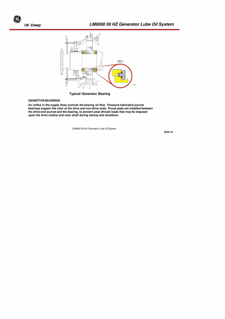
8/18/2019 71777896 - LM6000 Package Familiarization & Operations.pdf
http://slidepdf.com/reader/full/71777896-lm6000-package-familiarization-operationspdf 495/786
Slide 14
LM6000 50 Hz Generator Lube Oil System
Generator Gauge Panel
Located outside of the Generator enclosureis a local gauge panel. This monitoring
station gives local pressures of the JackingOil pump HP/LP elements. Located on theopposite side is a monitoring station for theAuxiliary oil pump discharge Gauge Panel.
LM6000 50 HZ Generator Lube Oil System GE EnergyGE EnergyGE EnergyGE Energy

8/18/2019 71777896 - LM6000 Package Familiarization & Operations.pdf
http://slidepdf.com/reader/full/71777896-lm6000-package-familiarization-operationspdf 496/786
Slide 15
LM6000 50 Hz Generator Lube Oil System
Lube Oil Rundown Tanks (4)
There are four rundown tanks. Twotanks are located on the generator,(one on each end of the generator)
and two located on the gearbox.Each tank has a 20 gal. (76 liters)capacity.
The rundown tanks are filled whenthe motor-driven pump is started.The rundown tank provides anemergency source of lube oil to the
bearings in case of pump failure.
LM6000 50 HZ Generator Lube Oil System GE EnergyGE EnergyGE EnergyGE Energy
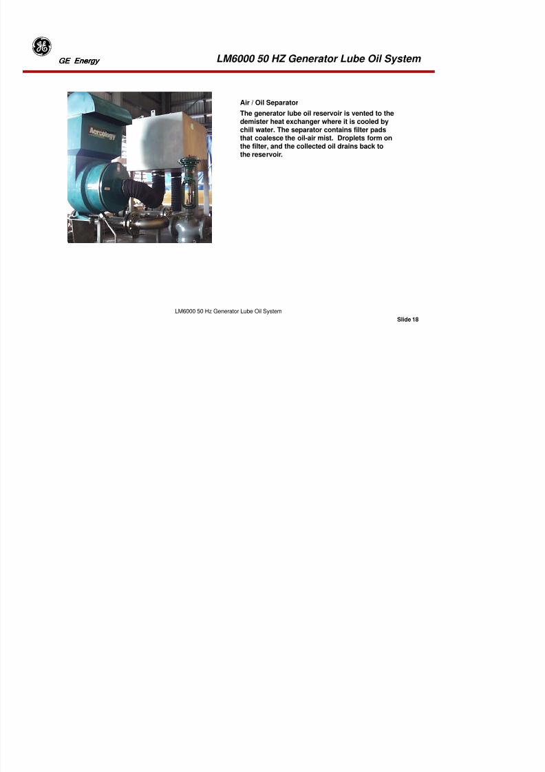
8/18/2019 71777896 - LM6000 Package Familiarization & Operations.pdf
http://slidepdf.com/reader/full/71777896-lm6000-package-familiarization-operationspdf 497/786
Slide 16
LM6000 50 Hz Generator Lube Oil System
GENERTOR BEARINGS
An orifice in the supply lines controls the bearing oil flow. Pressure-lubricated journal
bearings support the rotor at the drive and non-drive ends. Thrust pads are installed betweenthe drive-end journal and the bearing, to prevent axial (thrust) loads that may be imposedupon the drive turbine and rotor shaft during startup and shutdown.
Typical Generator Bearing
LM6000 50 HZ Generator Lube Oil System GE EnergyGE EnergyGE EnergyGE Energy
GENERATOR BEARINGS (CONT)
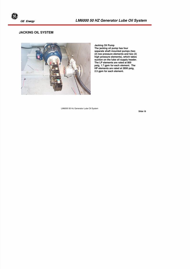
8/18/2019 71777896 - LM6000 Package Familiarization & Operations.pdf
http://slidepdf.com/reader/full/71777896-lm6000-package-familiarization-operationspdf 498/786
Slide 17
LM6000 50 Hz Generator Lube Oil System
GENERATOR BEARINGS (CONT).
The bearings are supported in fabricated steel housings, which are bolted directly to thegenerator ends. The bearing housings are split on the horizontal centerline with the lower halfforming the bearing oil sump. The bearings are of plain cylindrical design, white metal lining, andspherically seated within the bearing housings. Oil under pressure is fed to the bearings anddistributed over the bearing surface by internal grooves.
Oil drains into the bottom of the bearing housing. From the housing, the oil drains into the lubeoil return oil header.
LM6000 50 HZ Generator Lube Oil System GE EnergyGE EnergyGE EnergyGE Energy
8/18/2019 71777896 - LM6000 Package Familiarization & Operations.pdf
http://slidepdf.com/reader/full/71777896-lm6000-package-familiarization-operationspdf 499/786
Slide 18
LM6000 50 Hz Generator Lube Oil System
Air / Oil Separator
The generator lube oil reservoir is vented to thedemister heat exchanger where it is cooled bychill water. The separator contains filter pads
that coalesce the oil-air mist. Droplets form onthe filter, and the collected oil drains back tothe reservoir.
LM6000 50 HZ Generator Lube Oil System GE EnergyGE EnergyGE EnergyGE Energy
JACKING OIL SYSTEM
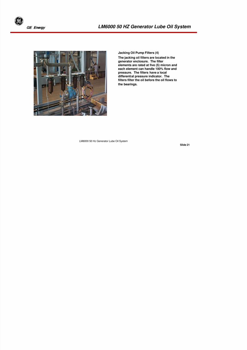
8/18/2019 71777896 - LM6000 Package Familiarization & Operations.pdf
http://slidepdf.com/reader/full/71777896-lm6000-package-familiarization-operationspdf 500/786
Slide 19
LM6000 50 Hz Generator Lube Oil System
Jacking Oil Pump
The jacking oil pump has fourseparate shaft mounted pumps (two(2) low pressure elements and two (2)high pressure elements), which takessuction on the lube oil supply header.The LP elements are rated at 800psig, 1.7 gpm for each element. TheHP elements are rated at 2850 psig,2.5 gpm for each element.
JACKING OIL SYSTEM
LM6000 50 HZ Generator Lube Oil System GE EnergyGE EnergyGE EnergyGE Energy
Low Pressure Element Relief Valves (PSV 6053 A/B)

8/18/2019 71777896 - LM6000 Package Familiarization & Operations.pdf
http://slidepdf.com/reader/full/71777896-lm6000-package-familiarization-operationspdf 501/786
Slide 20
LM6000 50 Hz Generator Lube Oil System
Low Pressure Element Relief Valves (PSV-6053 A/B)
A relief valve is located on the discharge side of each jacking oil pump, low-pressureelement. The relief valves protect the system from over-pressurization. The valves relieveback to the reservoir and is set to open at 1000 psig (6890 kPag).
High Pressure Element Relief Valves (PSV-6054 A/B)
A relief valve is located on the discharge side of each jacking oil pump high-pressureelement. The relief valves protect the system from over-pressurization. The valve relievesback to the reservoir and is set to open at 3000 psig (20670 kPag).
LM6000 50 HZ Generator Lube Oil System GE EnergyGE EnergyGE EnergyGE Energy
8/18/2019 71777896 - LM6000 Package Familiarization & Operations.pdf
http://slidepdf.com/reader/full/71777896-lm6000-package-familiarization-operationspdf 502/786
Slide 21
LM6000 50 Hz Generator Lube Oil System
Jacking Oil Pump Filters (4)
The jacking oil filters are located in thegenerator enclosure. The filterelements are rated at five (5) micron andeach element can handle 100% flow andpressure. The filters have a localdifferential pressure indicator. Thefilters filter the oil before the oil flows to
the bearings.
LM6000 50 HZ Generator Lube Oil System GE EnergyGE EnergyGE EnergyGE Energy
8/18/2019 71777896 - LM6000 Package Familiarization & Operations.pdf
http://slidepdf.com/reader/full/71777896-lm6000-package-familiarization-operationspdf 503/786
Slide 22
LM6000 50 Hz Generator Lube Oil System
Low Pressure Jacking Oil
The low-pressure (LP) jacking oil “lifts” the rotor shaft out of the bottom half of thebearing and “floats” the rotor shaft on a cushion of oil during unit startup. This makes therotor shaft easier to “break away” and start rotating.
High Pressure Jacking Oil
The high pressure (HP) jacking oil “pushes” the rotor shaft off the thrust bearing padsduring unit start up. This makes the rotor shaft easier to “break away” and start rotating.
Jacking Oil Return
The jacking oil is returned to the generator lube oil sump by the return oil header.
LM6000 50 HZ Generator Lube Oil System GE EnergyGE EnergyGE EnergyGE Energy
GENERATOR LUBE OIL OPERATION
8/18/2019 71777896 - LM6000 Package Familiarization & Operations.pdf
http://slidepdf.com/reader/full/71777896-lm6000-package-familiarization-operationspdf 504/786
Slide 23
LM6000 50 Hz Generator Lube Oil System
GENERATOR LUBE OIL OPERATION
Oil supply pressure gauges and filter differential pressure gauges are located on the generator gaugepanel outside the generator enclosure. Gauges, switches, and transmitters have isolation valves insensing lines to facilitate instrument maintenance or replacement.
Oil for generator-bearing lubrication and for jacking oil pump system operation is extracted from thelube oil reservoir by pumps and discharged into a common supply line. Ball valves on the pumpdischarge piping can isolate the pump from the common supply line.
Check valves prevent oil from flowing backwards. Oil discharge pressure for each pump is monitoredby pressure gauges. The pressure gauges are on the pump discharge side of the check valves to
ensure that only pump pressure (not lubricating oil manifold pressure) is measured. Each pressuregauge can be isolated from the pump discharge line. Pump A (AC-powered pump) pressure switchPSL-6073A is set to initiate an alarm at pressures 50 psig(345 kPaG). Pump B (AC-powered pump)pressure switch PSL-6073B is set to initiate an alarm also at pressures 50 psig (345 kPaG). Ifapplicable, emergency coastdown pump (DC-powered auxiliary pump) pressure switch PSL-6074
initiates an alarm at pressures 20 psig (138 kPag).
LM6000 50 HZ Generator Lube Oil System GE EnergyGE EnergyGE EnergyGE Energy

8/18/2019 71777896 - LM6000 Package Familiarization & Operations.pdf
http://slidepdf.com/reader/full/71777896-lm6000-package-familiarization-operationspdf 505/786
Slide 24
LM6000 50 Hz Generator Lube Oil System
Oil flow from the common supply manifold is routed to either (1) the lube oil heat exchanger and thenthe duplex filter, or (2) directly to the duplex filter (bypassing the heat exchanger assembly). Flow toand through the shell-tube heat exchangers, or flow around the heat exchangers, is controlled bythermostatic, 3-way control valve TCV-6065. This thermostatic control maintains an oil outlet
temperature of 140 °°°°F (60 °°°°C). If the oil temperature is > 140 °°°°F (60 °°°°C), the thermostatic valvemodulates closes and varies the oil flows through the heat exchanger.
The common supply line divides to supply lubrication simultaneously to the two generator bearingsas well as through the gearbox. Oil flow to the bearings is through check valves and orifices and forthe exciter-end and drive-end bearings, respectively. The check valves prevent oil backflow into thelube oil system during jacking oil pump operation.
Temperature elements TE-6023 and TE-6021 are installed in the exciter-end and drive-end bearings,respectively. Each element monitors the bearing temperature and transmits these values to the controlsystem. The control system initiates a high-temperature alarm at 197 °°°°F (92 °°°°C) and initiates a FSLOsystem shutdown at 203 °°°°F (95 °°°°C). Temperature elements TE-6035 and TE-6036 are installed in theexciter-end and drive-end bearing drain lines, respectively. Each element monitors bearing drain oiltemperatures and transmits these values to the control system. The control system initiates a high-
temperature alarm at 189 °°°°F (87 °°°°C) and initiates a FSLO system shutdown at 194 °°°°F (90 °°°°C).Temperature indicators TI-6012 and TI-6011, scaled 50−−−−400 °°°°F (10-200 °°°°C), indicate the bearing oildischarge temperatures for the exciter-end and drive-end bearings, respectively.
LM6000 50 HZ Generator Lube Oil System GE EnergyGE EnergyGE EnergyGE Energy
8/18/2019 71777896 - LM6000 Package Familiarization & Operations.pdf
http://slidepdf.com/reader/full/71777896-lm6000-package-familiarization-operationspdf 506/786
Slide 25
LM6000 50 Hz Generator Lube Oil System
Extensions of the lube oil supply lines to the generator bearings supply oil to fill two generator lubeoil rundown tanks that are designed to hold 20 gallons (76L) each. Mounted near the generatorhousing, the rundown tanks are positioned so that oil from the tanks flows by gravity into the lube oilsupply line. In the event of AC pump failure (or during emergency shutdown with the DC pump
operating), oil from the rundown tanks is supplied to the bearings through snubber orifices. Duringoperation, the tanks are maintained at capacity through the same oil supply lines. Each rundown tankhas a level switch: LS-6041 and LS-6042. If oil level in any tank is lower than 6 inches (152 mm) fromthe top of the tank, the associated level switch notifies the TCP. If the low level occurs 5 minutes afterstartup, the control system will abort the startup. If the low level occurs during operation at normalspeeds, the control system will initiate an alarm.
Lubricating oil flows through the generator bearing assemblies, then drains by gravity to the generatorlube oil reservoir. An oil flow indicator is located in each generator bearing drain line for visualverification of oil flow through the bearings.
LM6000 50 HZ Generator Lube Oil System GE EnergyGE EnergyGE EnergyGE Energy
Generator Lube Oil Features
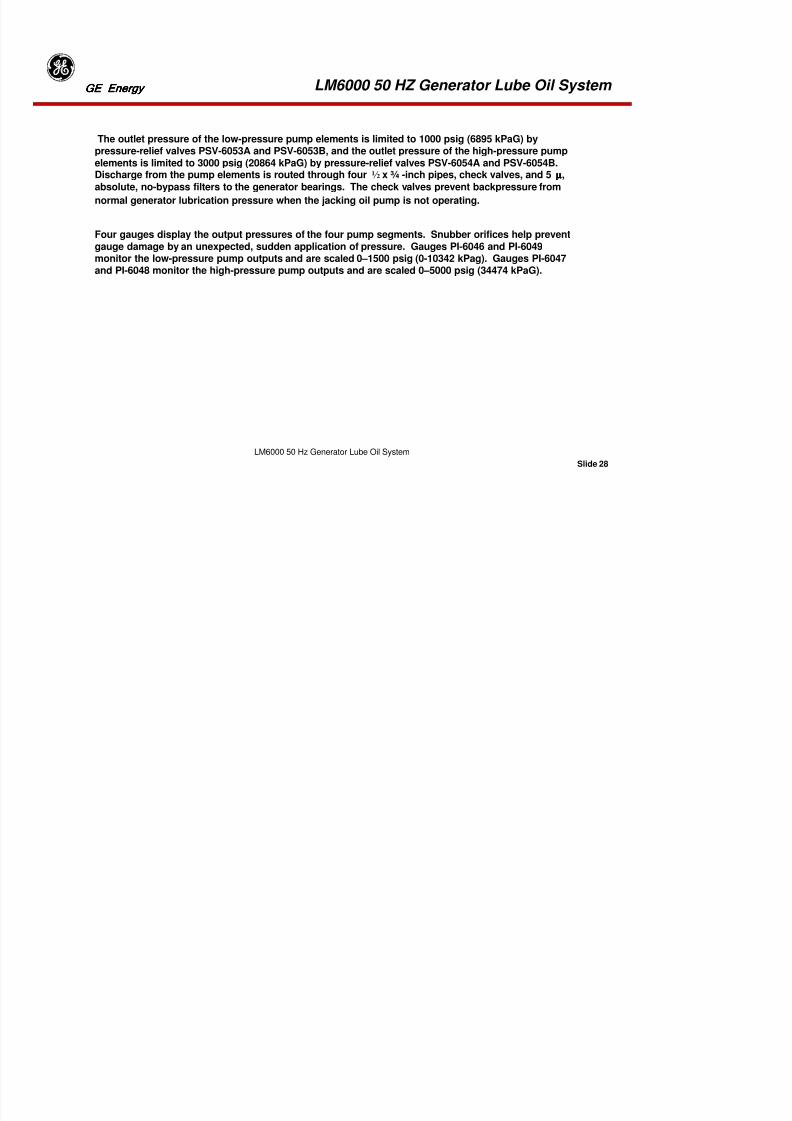
8/18/2019 71777896 - LM6000 Package Familiarization & Operations.pdf
http://slidepdf.com/reader/full/71777896-lm6000-package-familiarization-operationspdf 507/786
Slide 26
LM6000 50 Hz Generator Lube Oil System
Generator Lube Oil Features
Thermometers are mounted at appropriate points in the piping for direct observation of oiltemperatures. Pressure gauges mounted on the generator gauge panel provide direct indication oflubricating oil operating pressures. Jacking oil pressures are shown on the jacking oil gauge panel.Pressure switches and transmitters send pressure information to the control system. Temperature
sensors and transmitters send temperature information to the control system. Flow indicators inreturn and drain lines allow operators to inspect oil flows. Manually operated ball valves throughoutthe piping facilitate component maintenance. In addition to piping, valving, and certain pipe-mountedinstruments, the assemblies listed below make up the generator lube oil system.
LM6000 50 HZ Generator Lube Oil System GE EnergyGE EnergyGE EnergyGE Energy
Generator Jacking Oil Pump

8/18/2019 71777896 - LM6000 Package Familiarization & Operations.pdf
http://slidepdf.com/reader/full/71777896-lm6000-package-familiarization-operationspdf 508/786
Slide 27
LM6000 50 Hz Generator Lube Oil System
g p
Pressure gauges are located on the generator jacking oil gauge panel outside the generator enclosurewall. The pressure switches are located on the MGTB with the generator lube oil switches andtransmitters. Gauges and pressure switches have isolation valves in sensing lines to facilitateinstrument maintenance or replacement. Check valves prevent backflow of oil into the pump elements.
For jacking oil pump maintenance purposes, it is necessary that the main AC lube oil pump be inoperation. The four elements of the jacking oil pump take supply oil from the generator lube oilsystem, just downstream from the duplex filter. Inlet pressure may be monitored on jacking oilpressure indicator PI-6052. Jacking oil is drawn through a pump isolation valve and a four-branchmanifold via a 2-inch pipe to the four-pump suction inlets. Pump inlet pressure is monitored justdownstream from the pump isolation valve by pressure switch PSL-6050, which closes to initiate an
alarm if jacking pump inlet pressure is 10 psig (69 kPag), while pressure switch PSLL-6051 closes toinitiate a FSLO shutdown if the jacking oil inlet pressure is 5 psig 34 kPaG). As part of the systemstartup logic, the contacts of switch PSL-6050 must be open before the control system startuppermissive requirements are satisfied.
LM6000 50 HZ Generator Lube Oil System GE EnergyGE EnergyGE EnergyGE Energy
The outlet pressure of the low-pressure pump elements is limited to 1000 psig (6895 kPaG) by

8/18/2019 71777896 - LM6000 Package Familiarization & Operations.pdf
http://slidepdf.com/reader/full/71777896-lm6000-package-familiarization-operationspdf 509/786
Slide 28
LM6000 50 Hz Generator Lube Oil System
p p p p p g ( ) ypressure-relief valves PSV-6053A and PSV-6053B, and the outlet pressure of the high-pressure pumpelements is limited to 3000 psig (20864 kPaG) by pressure-relief valves PSV-6054A and PSV-6054B.Discharge from the pump elements is routed through four ½ x ¾ -inch pipes, check valves, and 5 µµµµ,
absolute, no-bypass filters to the generator bearings. The check valves prevent backpressure from
normal generator lubrication pressure when the jacking oil pump is not operating.
Four gauges display the output pressures of the four pump segments. Snubber orifices help preventgauge damage by an unexpected, sudden application of pressure. Gauges PI-6046 and PI-6049monitor the low-pressure pump outputs and are scaled 0–1500 psig (0-10342 kPag). Gauges PI-6047and PI-6048 monitor the high-pressure pump outputs and are scaled 0–5000 psig (34474 kPaG).
LM6000 50 HZ Generator Lube Oil System GE EnergyGE EnergyGE EnergyGE Energy
Generator Lube Oil Reservoir

8/18/2019 71777896 - LM6000 Package Familiarization & Operations.pdf
http://slidepdf.com/reader/full/71777896-lm6000-package-familiarization-operationspdf 510/786
Slide 29
LM6000 50 Hz Generator Lube Oil System
The generator lube oil reservoir has a 2640-gallon (9995 L) retention capacity (3000 gallon (11356L)capacity of mineral lubricating oil). The reservoir is filled via a fill cap and basket strainer, and maybe drained via a 2-inch drain valve. A plate-frame heat exchanger cools the lube oil before it enters theair-oil separator. The air-oil separator (demister), driven by a 3 -hp, 400 VAC, 3phase, 50-Hz motor,
allows entrained air to escape to the atmosphere while capturing oil droplets that are drained to thereservoir. Pressure indicator PI-6088 monitors reservoir pressure from the top of the reservoir.Demister pressure switch PSH-6089 closes at –1 inch (-25 mm) of water increasing and activates analarm.
Level gauge LG-6068, located on the side of the tank, provides for direct observation of oil levels in thetank. The tank heater is comprised of thermostatically controlled elements HE-6067A and HE-6067B
and switches TC-6077 and TSL-6020. The heaters warm the oil during cold-weather operation. Thecontrol switch energizes the heaters, as required, to maintain the temperature at 90 °°°°F (32 °°°°C).Temperature switch TSL-6020 signals the control system to initiate an alarm when oil temperaturedrops to 70 °°°°F (21 °°°°C). Alarm switch LSL-6001 signals the control system to initiate an alarm anddeenergize the lube oil heaters whenever the oil level drops 12 inches (305 mm) below the flange.Thermometer TI-6014, scaled 50−−−−400 °°°°F (10-200 °°°°C), measures actual lube oil temperature in thereservoir.
LM6000 50 HZ Generator Lube Oil System GE EnergyGE EnergyGE EnergyGE Energy
AC Generator Lube Oil Pumps
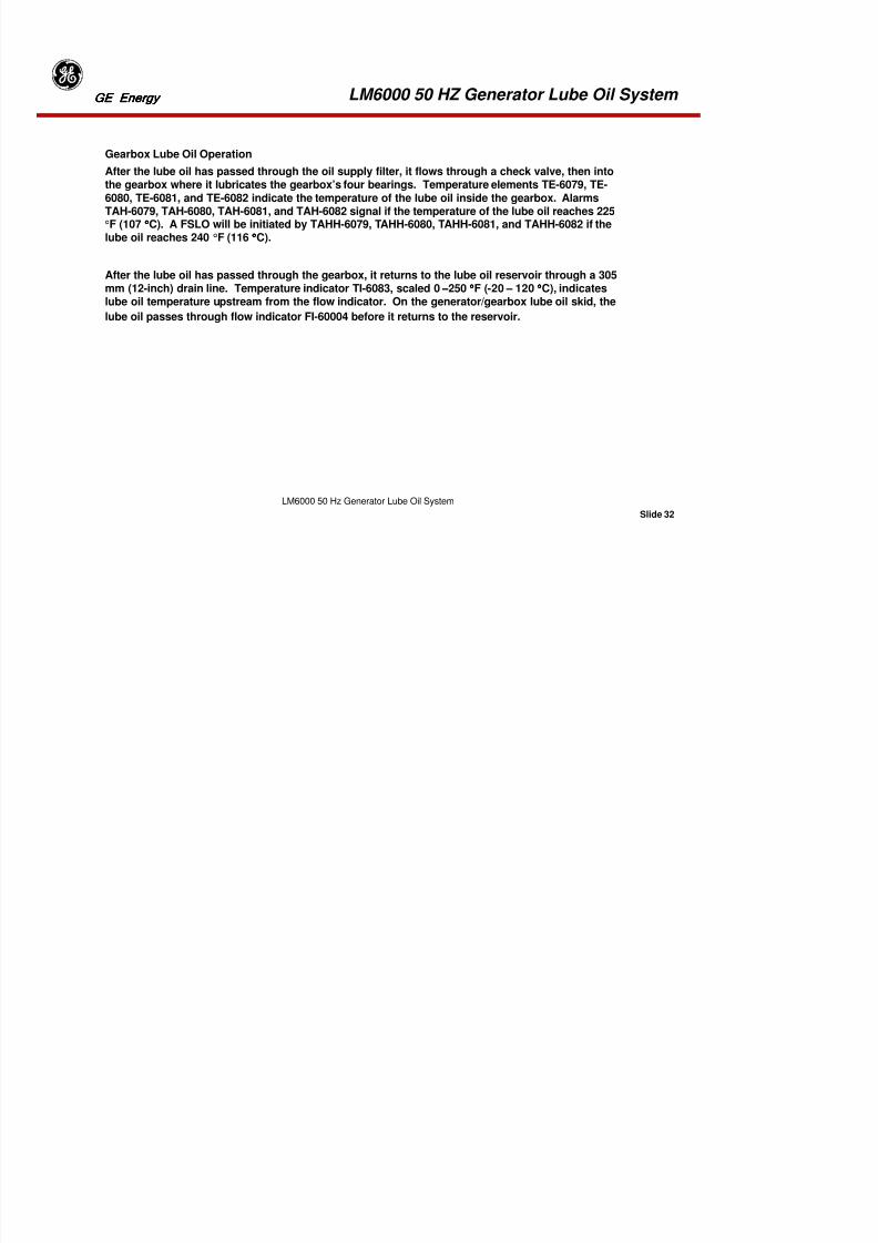
8/18/2019 71777896 - LM6000 Package Familiarization & Operations.pdf
http://slidepdf.com/reader/full/71777896-lm6000-package-familiarization-operationspdf 511/786
Slide 30
LM6000 50 Hz Generator Lube Oil System
The control system activates the AC motor, main lube oil pump (Pump A or Pump B) to provide oil tothe generator lube oil system. The standby pump will come on-line should the main pump fail. Themain and standby oil pumps are driven by 18.6 kW (25-hp), 400V, 3phase, 50-Hz, explosion-proof, ACmotors. Each pump is designed to deliver 330 gpm (1249 L/m) of oil. The control system monitors
generator speed and lube oil pressures and temperatures for indications of system malfunction.
Generator Lube Oil Heat ExchangerThe shell-tube heat exchanger assembly is located on the generator lube oil skid. The lube oil
may bypass the coolers if thermostatic control valve TCV-6065 determines the temperature to be<<<< 140°°°° F (60 °°°°C). After the lube oil passes through control valve TCV-6065, temperature indicatorTI-6070 measures actual lube oil temperature. This indicator is scaled 0−−−−250 °°°°F (-20 – 120 °°°°C).
LM6000 50 HZ Generator Lube Oil System GE EnergyGE EnergyGE EnergyGE Energy
Generator Oil Supply Filter

8/18/2019 71777896 - LM6000 Package Familiarization & Operations.pdf
http://slidepdf.com/reader/full/71777896-lm6000-package-familiarization-operationspdf 512/786
Slide 31
LM6000 50 Hz Generator Lube Oil System
pp y
The oil supply filter assembly is located on the generator lube oil skid. Identical in function to theturbine lube oil filter, the filter is a duplex, full-flow assembly, featuring two pressure-balancedfilters with replaceable 6-µ, absolute, filter elements. A manual transfer valve diverts oil flowthrough one element, allowing the other element to be serviced without interruption of operation.
A differential pressure gauge and switch warn operators of a dirty filter element. The instrumentsmay be isolated from the system by instrument valves. A differential pressure-balance valvepermits the equalization of pressure across the instruments. Differential pressure gauge PDI-6007indicates filter differential pressure in a range of 0–30 psid (0-207 kPaD), and differential pressureswitch PDSH-6015 signals the control system to initiate an alarm if the pressure drop across the oil
filter increases to 20 psid (138 kPaD).
LM6000 50 HZ Generator Lube Oil System GE EnergyGE EnergyGE EnergyGE Energy
Gearbox Lube Oil Operation
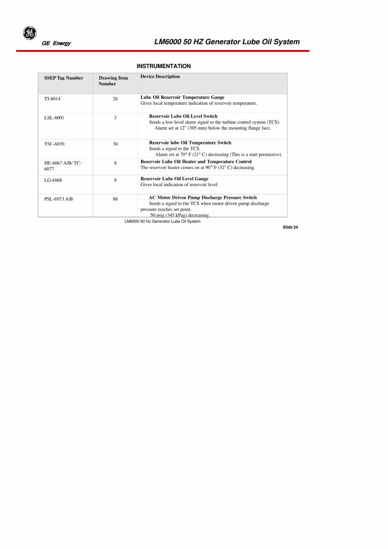
8/18/2019 71777896 - LM6000 Package Familiarization & Operations.pdf
http://slidepdf.com/reader/full/71777896-lm6000-package-familiarization-operationspdf 513/786
Slide 32
LM6000 50 Hz Generator Lube Oil System
After the lube oil has passed through the oil supply filter, it flows through a check valve, then intothe gearbox where it lubricates the gearbox’s four bearings. Temperature elements TE-6079, TE-6080, TE-6081, and TE-6082 indicate the temperature of the lube oil inside the gearbox. AlarmsTAH-6079, TAH-6080, TAH-6081, and TAH-6082 signal if the temperature of the lube oil reaches 225°F (107 °°°°C). A FSLO will be initiated by TAHH-6079, TAHH-6080, TAHH-6081, and TAHH-6082 if the
lube oil reaches 240 °F (116 °°°°C).
After the lube oil has passed through the gearbox, it returns to the lube oil reservoir through a 305mm (12-inch) drain line. Temperature indicator TI-6083, scaled 0−−−−250 °°°°F (-20 – 120 °°°°C), indicateslube oil temperature upstream from the flow indicator. On the generator/gearbox lube oil skid, the
lube oil passes through flow indicator FI-60004 before it returns to the reservoir.
LM6000 50 HZ Generator Lube Oil System GE EnergyGE EnergyGE EnergyGE Energy
MAINTENANCE INSPECTION/CHECK SCHEDULE

8/18/2019 71777896 - LM6000 Package Familiarization & Operations.pdf
http://slidepdf.com/reader/full/71777896-lm6000-package-familiarization-operationspdf 514/786
Slide 33
LM6000 50 Hz Generator Lube Oil System
Inspection
Check
Required
Inspection
Frequency
Maintenan
ce Level
Remarks
Generator
Frame
Monthly I Conduct general inspection
Grounding
System
Monthly I Verify shaft and frame grounding
Lube Oil Level Weekly I Check reservoir sight gauge.
Bearing Drains Weekly I Check that flow is maintained.
Vibration
Signatures
Weekly I Check Bently Nevada gauges for
measuring vibration.
MAINTENANCE INSPECTION/CHECK SCHEDULE
LM6000 50 HZ Generator Lube Oil System GE EnergyGE EnergyGE EnergyGE Energy
INSTRUMENTATION

8/18/2019 71777896 - LM6000 Package Familiarization & Operations.pdf
http://slidepdf.com/reader/full/71777896-lm6000-package-familiarization-operationspdf 515/786
Slide 34
LM6000 50 Hz Generator Lube Oil System
SSEP Tag Number Drawing Item
Number
Device Description
TI-6014 26Lube Oil Reservoir Temperature Gauge
Gives local temperature indication of reservoir temperature.
LSL-6001 3 Reservoir Lube Oil Level Switch
Sends a low-level alarm signal to the turbine control system (TCS).
Alarm set at 12” (305 mm) below the mounting flange face.
TSL-6020 30 Reservoir lube Oil Temperature SwitchSends a signal to the TCS.
Alarm set at 70° F (21° C) decreasing (This is a start permissive).
HE-6067 A/B/ TC-
6077
8 Reservoir Lube Oil Heater and Temperature Control
The reservoir heater comes on at 90° F (32° C) decreasing.
LG-6068 9 Reservoir Lube Oil Level Gauge
Gives local indication of reservoir level.
PSL-6073 A/B 88 AC Motor Driven Pump Discharge Pressure Switch
Sends a signal to the TCS when motor driven pump discharge
pressure reaches set point.
50 psig (345 kPag) decreasing.
LM6000 50 HZ Generator Lube Oil System GE EnergyGE EnergyGE EnergyGE Energy
D i D i i
INSTRUMENTATION

8/18/2019 71777896 - LM6000 Package Familiarization & Operations.pdf
http://slidepdf.com/reader/full/71777896-lm6000-package-familiarization-operationspdf 516/786
Slide 35
LM6000 50 Hz Generator Lube Oil System
SSEP Tag Number Drawing Item
Number
Device Description
PSL-6074 90 DC Motor Driven Pump Discharge Pressure Switch
Sends an alarm signal to the TCS if DC motor driven pump
discharge pressure has decreased below the required set point.
Alarm set point set at 20 psig (138 kPag) decreasing.
TI-6071 22 Lube Oil Pump Discharge Temperature Gauge
Gives local indication of lube oil pump discharge temperature.
TI-6070 22Lube Oil Cooler Discharge Temperature Gauge
Gives local indication of lube oil cooler discharge temperature.
LM6000 50 HZ Generator Lube Oil System GE EnergyGE EnergyGE EnergyGE Energy
INSTRUMENTATION
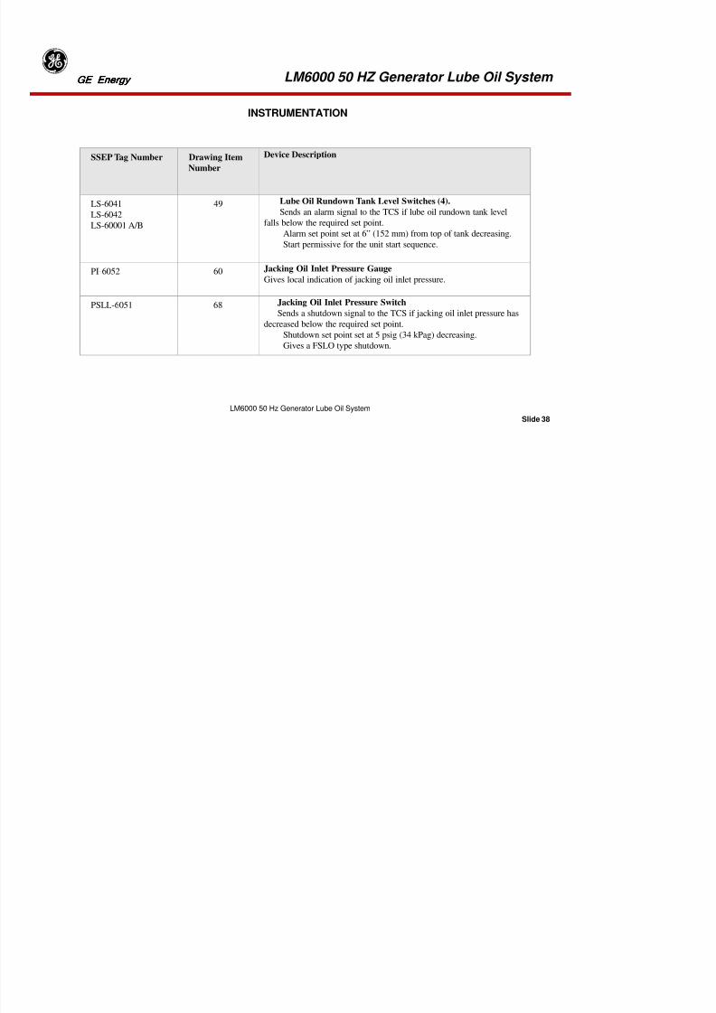
8/18/2019 71777896 - LM6000 Package Familiarization & Operations.pdf
http://slidepdf.com/reader/full/71777896-lm6000-package-familiarization-operationspdf 517/786
Slide 36
LM6000 50 Hz Generator Lube Oil System
PDI-6007 20 Lube Oil Filter Differential Pressure Gauge
Gives local indication of supply filter ∆P.
PDSH-6015 28 Lube Oil Supply Filter Differential Pressure Switch
Gives an alarm if supply filter ∆P exceeds set point.
Alarm set at 20 psid (138 kPad) Increasing.
PI-6008 21 Lube Oil Supply Header Pressure Gauge
Gives local indication of supply header pressure.
PT-6026 33 Lube Oil Supply Header Pressure Transmitter
Gives remote indication of supply header pressure.
SSEP Tag
Number
Drawing Item
Number
Device Description
LM6000 50 HZ Generator Lube Oil System GE EnergyGE EnergyGE EnergyGE Energy
INSTRUMENTATION

8/18/2019 71777896 - LM6000 Package Familiarization & Operations.pdf
http://slidepdf.com/reader/full/71777896-lm6000-package-familiarization-operationspdf 518/786
Slide 37
LM6000 50 Hz Generator Lube Oil System
PSL-6018 29 Lube Oil Supply Header Alarm Pressure Switch
Sends an alarm signal to the TCS if lube oil supply header pressure
has decreased below the required set point.
Alarm set point set at 20 psig (138 kPag) decreasing.
Starts the opposite AC motor driven lube oil supply pump.
PSLL-6019 29 Lube Oil Supply Header Shutdown Pressure Switch
Sends a shutdown signal to the TCS if lube oil supply header
pressure has decreased below the required set point.
Shutdown set point set at 12 psig (82 kPag) decreasing.
Gives a FSLO type shutdown. Start DC motor driven pump
SSEP Tag Number Drawing Item
Number
Device Description
LM6000 50 HZ Generator Lube Oil System GE EnergyGE EnergyGE EnergyGE Energy
INSTRUMENTATION

8/18/2019 71777896 - LM6000 Package Familiarization & Operations.pdf
http://slidepdf.com/reader/full/71777896-lm6000-package-familiarization-operationspdf 519/786
Slide 38
LM6000 50 Hz Generator Lube Oil System
SSEP Tag Number Drawing Item
Number
Device Description
LS-6041
LS-6042
LS-60001 A/B
49 Lube Oil Rundown Tank Level Switches (4).
Sends an alarm signal to the TCS if lube oil rundown tank level
falls below the required set point.
Alarm set point set at 6” (152 mm) from top of tank decreasing.
Start permissive for the unit start sequence.
PI-6052 60 Jacking Oil Inlet Pressure GaugeGives local indication of jacking oil inlet pressure.
PSLL-6051 68 Jacking Oil Inlet Pressure Switch
Sends a shutdown signal to the TCS if jacking oil inlet pressure has
decreased below the required set point.
Shutdown set point set at 5 psig (34 kPag) decreasing.
Gives a FSLO type shutdown.
LM6000 50 HZ Generator Lube Oil System GE EnergyGE EnergyGE EnergyGE Energy
SSEP Tag Drawing Device Description
INSTRUMENTATION

8/18/2019 71777896 - LM6000 Package Familiarization & Operations.pdf
http://slidepdf.com/reader/full/71777896-lm6000-package-familiarization-operationspdf 520/786
Slide 39
LM6000 50 Hz Generator Lube Oil System
PI-6046, PI-
6049
57 Jacking Oil Pump Low Pressure Discharge Gauge
Gives local indication of jacking oil low-pressure dischargepressure.
PI-6047, PI-
6048
58 Jacking Oil Pump High Pressure Discharge Gauge
Gives local indication of jacking oil high-pressure
discharge pressure.
Ti-6069 22 Lube Oil Cooler Discharge Temperature
Gives local indication of oil temperature on discharge of
cooler prior to entering the thermostatic control valve
PSH-6089 86 Reservoir Pressure Switch High
Sends an alarm signal to the TCS if oil reservoir
pressure has decreased below the required set point.Alarm setpoint –1” (-25mm) H2O Increasing
SSEP Tag
Number
Drawing
Item
Number
Device Description
LM6000 50 HZ Generator Lube Oil System GE EnergyGE EnergyGE EnergyGE Energy
D i D i ti
INSTRUMENTATION

8/18/2019 71777896 - LM6000 Package Familiarization & Operations.pdf
http://slidepdf.com/reader/full/71777896-lm6000-package-familiarization-operationspdf 521/786
Slide 40
LM6000 50 Hz Generator Lube Oil System
PI-6088 87Reservoir Pressure Gage
Gives local indication of reservoir pressure
TE-6079
TE-6080
TE-6081
TE- 6082
77 Gearbox Bearing Temperature Elements
Sends an alarm / shutdown signal to the TCS if oil
pressure has decreased below the required set point.
Alarm setpoint: 225°F (107°C)
FSLO Shutdown: 240°F (116°C)
TI-6012
TI-6011
24 Generator Bearing Oil Discharge Temp Indicator
Gives local indication of generator bearing oil discharge
temperature.
TI-6083 79 Gearbox Bearing Oil Discharge Temp Indicator
Gives local indication of gearbox bearing oil discharge
temperature.
SSEP Tag
Number
Drawing
Item
Number
Device Description
LM6000 50 HZ Generator Lube Oil System GE EnergyGE EnergyGE EnergyGE Energy
SSEP Tag Drawing Device Description
INSTRUMENTATION
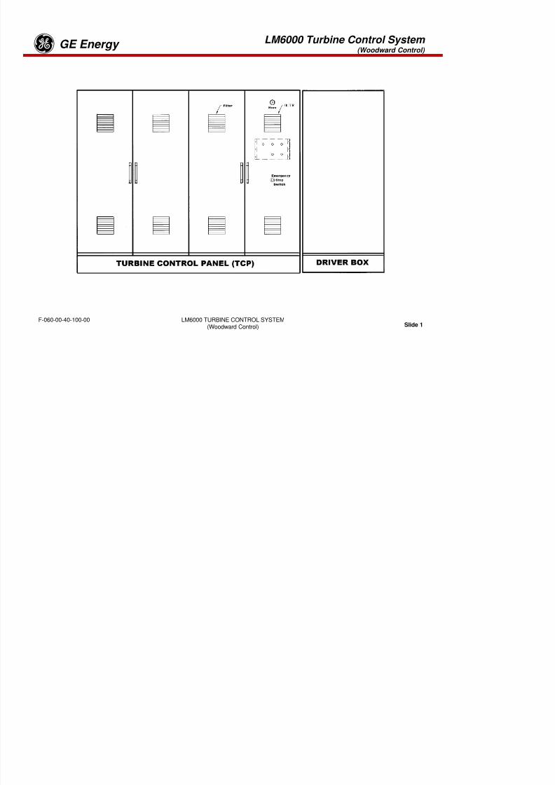
8/18/2019 71777896 - LM6000 Package Familiarization & Operations.pdf
http://slidepdf.com/reader/full/71777896-lm6000-package-familiarization-operationspdf 522/786
Slide 41
LM6000 50 Hz Generator Lube Oil System
Number Item
Number
TE-6084 75, 80 Gearbox Bearing Oil Discharge Temp Indicator
Sends a signal to the TCS displaying gearbox bearing oil
discharge temperature.
FI-60002
FI-60003
19 Generator Bearing Discharge Flow Discharge Indicator
Gives a local visual indication of generator bearing
discharge flow.
FI-60004 78 Gearbox Bearing Discharge Flow Discharge Indicator
Gives a local visual indication of gearbox bearing discharge
flow.
Tab 16
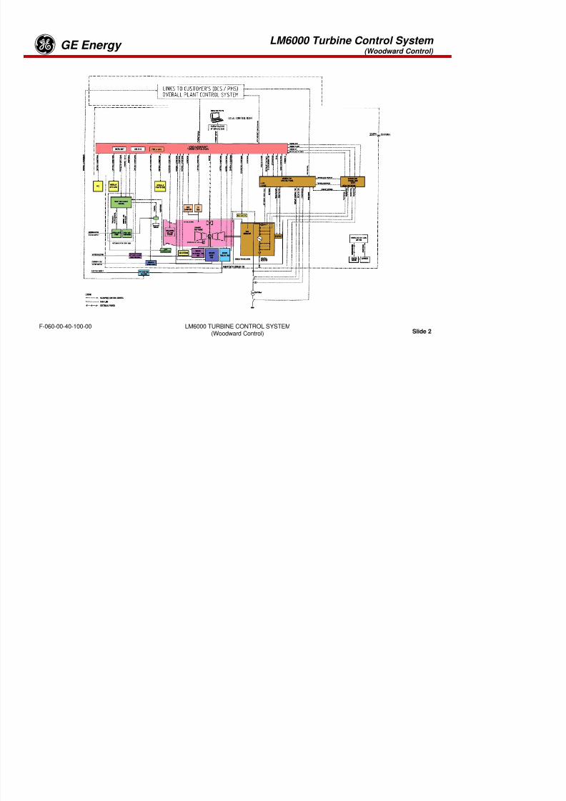
8/18/2019 71777896 - LM6000 Package Familiarization & Operations.pdf
http://slidepdf.com/reader/full/71777896-lm6000-package-familiarization-operationspdf 523/786
LM6000 Turbine Control System (Woodward Control)
GE Energyg

8/18/2019 71777896 - LM6000 Package Familiarization & Operations.pdf
http://slidepdf.com/reader/full/71777896-lm6000-package-familiarization-operationspdf 524/786
LM6000 TURBINE CONTROL SYSTEM(Woodward Control) Slide 1
F-060-00-40-100-00
LM6000 Turbine Control System (Woodward Control)
GE Energyg

8/18/2019 71777896 - LM6000 Package Familiarization & Operations.pdf
http://slidepdf.com/reader/full/71777896-lm6000-package-familiarization-operationspdf 525/786
LM6000 TURBINE CONTROL SYSTEM(Woodward Control) Slide 2
F-060-00-40-100-00
LM6000 Turbine Control System (Woodward Control)
GE Energyg
Turbine Control Panel
The Turbine-Generator Control Panel (TCP) and Generator Control Panel are the focal point foroperating the gas turbine generator system. The panels use solid-state electronics and is suitable forinstallation in a non hazardous local control room near the gas turbine generator
8/18/2019 71777896 - LM6000 Package Familiarization & Operations.pdf
http://slidepdf.com/reader/full/71777896-lm6000-package-familiarization-operationspdf 526/786
LM6000 TURBINE CONTROL SYSTEM(Woodward Control) Slide 3
F-060-00-40-100-00
installation in a non-hazardous local control room near the gas turbine generator.The TCP and GCP includes the following:
•Woodward Netcon microprocessor based digital fuel controller and sequencer•Digital vibration monitor•M-3425 digital multi-function generator protective relay system•Digital auto/manual voltage regulator•Auto and manual synchronization•Multi-function digital meter for electrical power values•Human-Machine Interface that provides graphic “screens”•Operator control switches and push buttons
•Serial output and Ethernet data port for customer's DCS•Parallel printer port
LM6000 Turbine Control System (Woodward Control)
GE Energyg

8/18/2019 71777896 - LM6000 Package Familiarization & Operations.pdf
http://slidepdf.com/reader/full/71777896-lm6000-package-familiarization-operationspdf 527/786
LM6000 TURBINE CONTROL SYSTEM(Woodward Control) Slide 4
F-060-00-40-100-00
WOODWARD MICRONET
LM6000 Turbine Control System (Woodward Control)
GE Energyg
The turbine-generator control system detects turbine engine and generator parameters;responds to operator directions; and performs fuel management, startup, shutdownsequencing, and electric power generator synchronization. The unit also senses unsafeconditions generates operator alarms and shuts down the engine when necessary to avoid

8/18/2019 71777896 - LM6000 Package Familiarization & Operations.pdf
http://slidepdf.com/reader/full/71777896-lm6000-package-familiarization-operationspdf 528/786
LM6000 TURBINE CONTROL SYSTEM(Woodward Control) Slide 5
F-060-00-40-100-00
conditions, generates operator alarms, and shuts down the engine when necessary to avoiddanger to personnel or equipment.
Starting and stopping the gas turbine engine or changing its modes of operation must beaccomplished in a sequence that considers engine reliability and personnel safety. Prior tostartup, ventilation fans and lube oil pumps must be in operation, engine and startingsubsystem status must be verified, and operator mode selections and start authorizationmust be given. After startup has been initiated, fuel system initialization must proceedignition and warm-up intervals must be satisfied before the engine is permitted to accelerate.Synchronism to the electric utility feed bus must then be established and the generatoroutput circuit breaker closed. These sequential operations are all controlled by the turbine-
generator control system.
The MicroNet control system implements Woodward’s real time operating system. Thecontrol is based on a 5 millisecond interrupt (the Minor Frame Timer or MFT). The operatingsystem schedules application tasks and control algorithms at the beginning of each MFT. Inthe application program each part or function of the application is executed in a scheduledmultiple of the MFT called a rate group, or RG. In this manner, all tasks or control functions
are implemented exactly at a scheduled time, which allows for accurate and consistentcontrol dynamics. The tool used to develop this program is the Graphical ApplicationProgram (GAP). GAP is a Woodward developed Windows based program that usesstandard blocks to develop an application.
LM6000 Turbine Control System (Woodward Control)
GE Energyg
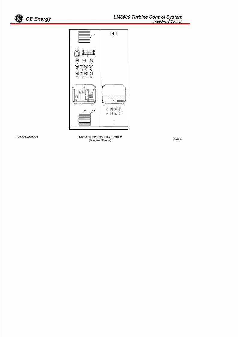
8/18/2019 71777896 - LM6000 Package Familiarization & Operations.pdf
http://slidepdf.com/reader/full/71777896-lm6000-package-familiarization-operationspdf 529/786
LM6000 TURBINE CONTROL SYSTEM(Woodward Control) Slide 6
F-060-00-40-100-00
TYPICAL I/O LINKNET MODULES
LM6000 Turbine Control System (Woodward Control)
GE Energyg
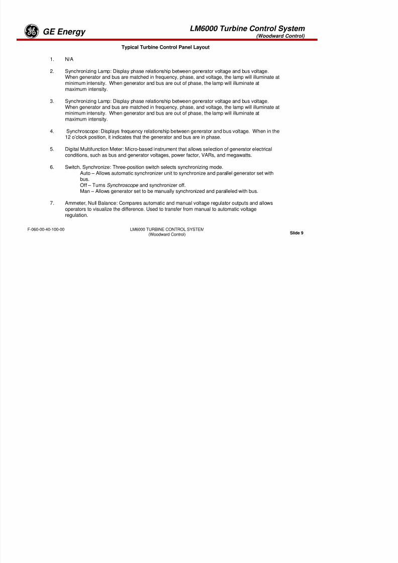
8/18/2019 71777896 - LM6000 Package Familiarization & Operations.pdf
http://slidepdf.com/reader/full/71777896-lm6000-package-familiarization-operationspdf 530/786
LM6000 TURBINE CONTROL SYSTEM(Woodward Control) Slide 7
F-060-00-40-100-00
BENTLEY 3500 RACK & FIRE PROTECTION PANEL
LM6000 Turbine Control System (Woodward Control)
GE Energyg

8/18/2019 71777896 - LM6000 Package Familiarization & Operations.pdf
http://slidepdf.com/reader/full/71777896-lm6000-package-familiarization-operationspdf 531/786
LM6000 TURBINE CONTROL SYSTEM(Woodward Control) Slide 8
F-060-00-40-100-00
LM6000 Turbine Control System (Woodward Control)
GE EnergygTypical Turbine Control Panel Layout
1. N/A
2. Synchronizing Lamp: Display phase relationship between generator voltage and bus voltage.When generator and bus are matched in frequency, phase, and voltage, the lamp will illuminate atminimum intensity. When generator and bus are out of phase, the lamp will illuminate at
i i i
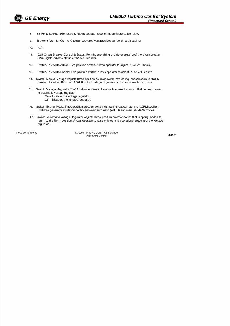
8/18/2019 71777896 - LM6000 Package Familiarization & Operations.pdf
http://slidepdf.com/reader/full/71777896-lm6000-package-familiarization-operationspdf 532/786
LM6000 TURBINE CONTROL SYSTEM(Woodward Control) Slide 9
F-060-00-40-100-00
maximum intensity.
3. Synchronizing Lamp: Display phase relationship between generator voltage and bus voltage.When generator and bus are matched in frequency, phase, and voltage, the lamp will illuminate atminimum intensity. When generator and bus are out of phase, the lamp will illuminate atmaximum intensity.
4. Synchroscope: Displays frequency relationship between generator and bus voltage. When in the12 o’clock position, it indicates that the generator and bus are in phase.
5. Digital Multifunction Meter: Micro-based instrument that allows selection of generator electricalconditions, such as bus and generator voltages, power factor, VARs, and megawatts.
6. Switch, Synchronize: Three-position switch selects synchronizing mode.Auto – Allows automatic synchronizer unit to synchronize and parallel generator set withbus.Off – Turns Synchroscope and synchronizer off.Man – Allows generator set to be manually synchronized and paralleled with bus.
7. Ammeter, Null Balance: Compares automatic and manual voltage regulator outputs and allowsoperators to visualize the difference. Used to transfer from manual to automatic voltageregulation.
LM6000 Turbine Control System (Woodward Control)
GE Energyg

8/18/2019 71777896 - LM6000 Package Familiarization & Operations.pdf
http://slidepdf.com/reader/full/71777896-lm6000-package-familiarization-operationspdf 533/786
LM6000 TURBINE CONTROL SYSTEM(Woodward Control) Slide 10
F-060-00-40-100-00
LM6000 Turbine Control System (Woodward Control)
GE Energyg
8. 86 Relay Lockout (Generator): Allows operator reset of the 86G protective relay.
9. Blower & Vent for Control Cubicle: Louvered vent provides airflow through cabinet.
10. N/A

8/18/2019 71777896 - LM6000 Package Familiarization & Operations.pdf
http://slidepdf.com/reader/full/71777896-lm6000-package-familiarization-operationspdf 534/786
LM6000 TURBINE CONTROL SYSTEM(Woodward Control) Slide 11
F-060-00-40-100-00
11. 52G Circuit Breaker Control & Status: Permits energizing and de-energizing of the circuit breaker52G. Lights indicate status of the 52G breaker.
12. Switch, PF/VARs Adjust: Two-position switch. Allows operator to adjust PF or VAR levels.
13. Switch, PF/VARs Enable: Two-position switch. Allows operator to select PF or VAR control
14. Switch, Manual Voltage Adjust: Three-position selector switch with spring-loaded return to NORMposition. Used to RAISE or LOWER output voltage of generator in manual excitation mode.
15. Switch, Voltage Regulator “On/Off” (Inside Panel): Two-position selector switch that controls powerto automatic voltage regulator.
On – Enables the voltage regulator.Off – Disables the voltage regulator.
16. Switch, Exciter Mode: Three-position selector switch with spring-loaded return to NORM position.Switches generator excitation control between automatic (AUTO) and manual (MAN) modes.
17. Switch, Automatic voltage Regulator Adjust: Three-position selector switch that is spring-loaded toreturn to the Norm position. Allows operator to raise or lower the operational setpoint of the voltageregulator.
LM6000 Turbine Control System (Woodward Control)
GE Energyg
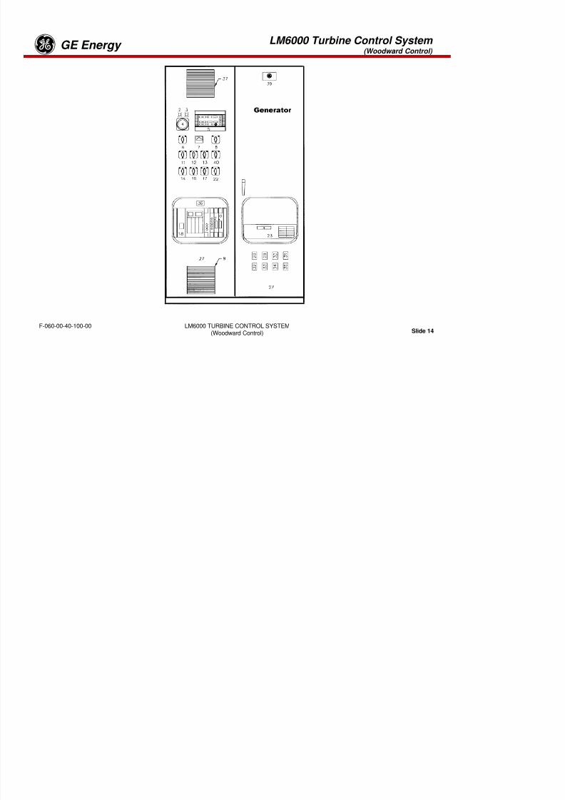
8/18/2019 71777896 - LM6000 Package Familiarization & Operations.pdf
http://slidepdf.com/reader/full/71777896-lm6000-package-familiarization-operationspdf 535/786
LM6000 TURBINE CONTROL SYSTEM(Woodward Control) Slide 12
F-060-00-40-100-00
LM6000 Turbine Control System (Woodward Control)
GE Energyg
18. Regulator, Auto/Manual Voltage: Selector switch with spring-loaded return to NORM position.Switches generator voltage control between automatic (AUTO) and manual (MAN) modes.
19. N/A
20. N/A

8/18/2019 71777896 - LM6000 Package Familiarization & Operations.pdf
http://slidepdf.com/reader/full/71777896-lm6000-package-familiarization-operationspdf 536/786
LM6000 TURBINE CONTROL SYSTEM(Woodward Control) Slide 13
F-060-00-40-100-00
21. N/A
22. Switch, Speed Adjust: Three-position selector switch that is spring-loaded to return to the Normposition. Used to Lower or Raise speed adjustment signals to the turbine control system.
23. Integrated Generator Protection System: Provides protective relay functions implemented digitallyfor the generator and its associated equipment. (See Generator Protective Relay System sectionfor details.)
24. N/A
25. N/A
26. N/A
27. Access Door: Doors allowing access to cubicle.
LM6000 Turbine Control System (Woodward Control)
GE Energyg

8/18/2019 71777896 - LM6000 Package Familiarization & Operations.pdf
http://slidepdf.com/reader/full/71777896-lm6000-package-familiarization-operationspdf 537/786
LM6000 TURBINE CONTROL SYSTEM(Woodward Control) Slide 14
F-060-00-40-100-00
LM6000 Turbine Control System (Woodward Control)
GE Energyg28. Switches, Test, Bus Voltage –
29. Switches, Test, Generator Voltage –
30. Switches, Test, Generator Current Metering –
31 Switches Test Bus Current Protection –

8/18/2019 71777896 - LM6000 Package Familiarization & Operations.pdf
http://slidepdf.com/reader/full/71777896-lm6000-package-familiarization-operationspdf 538/786
LM6000 TURBINE CONTROL SYSTEM(Woodward Control) Slide 15
F-060-00-40-100-00
31. Switches, Test, Bus Current Protection –
32. Switches, Test, Generator Current Protection
33. Switches, Test, Bus Voltage (52U) –
34. Switches, Test, Utility Voltage (52U) –
35. Switches, Test, Generator Lockout Relay (86G) –
36. Digital Synchronizer Module:
37. Filter, Control Cubicle: Louvered vent provides airflow through the cabinet.
38. N/A
39. Nameplate: Nameplate identifying the control cubicle
40. Switch, Circuit Breaker Control and Status (52U) - Permits energizing and deenergizing ofthe circuit breaker 52G.
LM6000 Turbine Control System (Woodward Control)
GE Energyg
MICRONET CHASSIS

8/18/2019 71777896 - LM6000 Package Familiarization & Operations.pdf
http://slidepdf.com/reader/full/71777896-lm6000-package-familiarization-operationspdf 539/786
LM6000 TURBINE CONTROL SYSTEM(Woodward Control) Slide 16
F-060-00-40-100-00
LM6000 Turbine Control System (Woodward Control)
GE Energyg
The MicroNet Chassis is designed around a modular six slot chassis (block). Each block consists of apre-molded cage with a fan for cooling and a temperature switch for high temperature detection. A forcedair-cools the chassis, and either a module or module blank must be installed in every slot to maintaincorrect airflow. The fans run whenever power is applied to the system.
The Simplex twelve slot MicroNet control utilized in this system, is composed of three blocks with a

8/18/2019 71777896 - LM6000 Package Familiarization & Operations.pdf
http://slidepdf.com/reader/full/71777896-lm6000-package-familiarization-operationspdf 540/786
LM6000 TURBINE CONTROL SYSTEM(Woodward Control) Slide 17
F-060-00-40-100-00
p y pmotherboard inserted in the back of the assembly to make connections between the fans, switches,power supplies, and control modules.
LM6000 Turbine Control System (Woodward Control)
GE Energyg

8/18/2019 71777896 - LM6000 Package Familiarization & Operations.pdf
http://slidepdf.com/reader/full/71777896-lm6000-package-familiarization-operationspdf 541/786
LM6000 TURBINE CONTROL SYSTEM(Woodward Control) Slide 18
F-060-00-40-100-00
LM6000 Turbine Control System (Woodward Control)
GE EnergygWINDOWS NT CPU MODULE
Every Simplex MicroNet control contains one CPU module located in the first slot of the MicroNet chassis. Thedescription of the CPU module contained in this chapter is the Windows® NT™ CPU.
The NT CPU module runs the application program. This module is a standard PC on a VME card. It supportsWindows NT with real-time extensions to maintain a rigorous real-time environment. NT functions are not re-documented in this manual

8/18/2019 71777896 - LM6000 Package Familiarization & Operations.pdf
http://slidepdf.com/reader/full/71777896-lm6000-package-familiarization-operationspdf 542/786
LM6000 TURBINE CONTROL SYSTEM(Woodward Control) Slide 19
F-060-00-40-100-00
documented in this manual.
There is a solid state Hard-Drive on the module which uses the standard Windows file system. The hard-drive hasWindows NT Operating System with the real-time extensions and the Application program. It has a standardinterface to the VME bus to read and write to I/O modules
LM6000 Turbine Control System (Woodward Control)
GE Energyg
INPUT FLOW

8/18/2019 71777896 - LM6000 Package Familiarization & Operations.pdf
http://slidepdf.com/reader/full/71777896-lm6000-package-familiarization-operationspdf 543/786
LM6000 TURBINE CONTROL SYSTEM(Woodward Control) Slide 20
F-060-00-40-100-00
OUTPUT FLOW
LM6000 Turbine Control System (Woodward Control)
GE Energyg
INPUTS AND OUTPUTS
The MicroNet platform is developed around the VME chassis and the CPU module that goes into the firstactive slot of the VME chassis. All I/O modules plug into the remaining slots of the VME chassis.E i h i b d t ll dditi l I/O d l E h I/O d l h t th

8/18/2019 71777896 - LM6000 Package Familiarization & Operations.pdf
http://slidepdf.com/reader/full/71777896-lm6000-package-familiarization-operationspdf 544/786
LM6000 TURBINE CONTROL SYSTEM(Woodward Control) Slide 21
F-060-00-40-100-00
Expansion chassis can be used to allow additional I/O modules. Each I/O module has connectors on thefaceplate. For analog and discrete I/O, cables connect to the module to a Field Terminal module (FTM).
The FTM is used to connect to the field wiring. For communication modules, FTMs are not used. Cablesare connected directly to the faceplate of the communications module. The following diagram shows theflow of analog and discrete inputs from the field to the application.
LM6000 Turbine Control System (Woodward Control)
GE Energyg
MICRONET SIMPLEX POWER SUPPLIESThe MicroNet Simplex control may use either single or redundant power supplies. A motherboard locatedon the back of the chassis allows the two power supplies to form a redundant power system providing:
•Two separately regulated, 24 Vdc, 12 A outputs,•Two separately regulated, 5 Vdc, 20 A outputs•Two separately regulated, 5 Vdc precharge outputs to the control.

8/18/2019 71777896 - LM6000 Package Familiarization & Operations.pdf
http://slidepdf.com/reader/full/71777896-lm6000-package-familiarization-operationspdf 545/786
LM6000 TURBINE CONTROL SYSTEM(Woodward Control) Slide 22
F-060-00-40-100-00
Power output regulation, including line, load, and temperature effects, is less than ± 5%.
When redundant power supplies are running, current sharing circuitry balances the load to reduce heatand improve the reliability of the power supplies. In the event that one supply needs replacement, thisfeature also ensures hot replacement of the power supplies without disrupting the operation of the control.
Each main power supply has four LEDs to indicate power supply health•OK•Input Fault•Overtemperature•Power Supply Fault
LM6000 Turbine Control System (Woodward Control)
GE EnergygOPERATOR SCREENS

8/18/2019 71777896 - LM6000 Package Familiarization & Operations.pdf
http://slidepdf.com/reader/full/71777896-lm6000-package-familiarization-operationspdf 546/786
LM6000 TURBINE CONTROL SYSTEM(Woodward Control) Slide 23
F-060-00-40-100-00
MAIN MENU
LM6000 Turbine Control System (Woodward Control)
GE Energyg
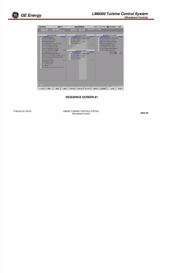
8/18/2019 71777896 - LM6000 Package Familiarization & Operations.pdf
http://slidepdf.com/reader/full/71777896-lm6000-package-familiarization-operationspdf 547/786
LM6000 TURBINE CONTROL SYSTEM(Woodward Control) Slide 24
F-060-00-40-100-00
MAIN TURBINE OVERVIEW
LM6000 Turbine Control System (Woodward Control)
GE Energyg
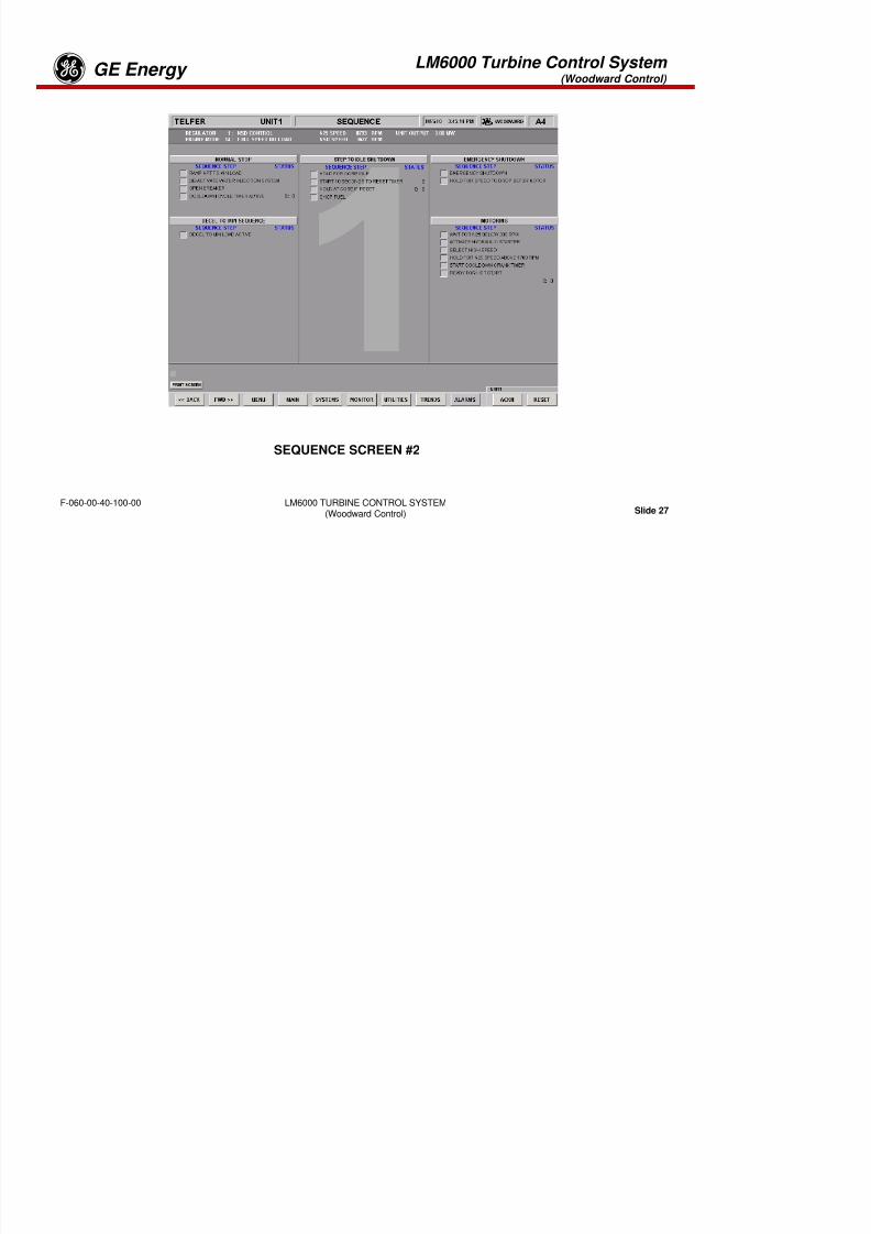
8/18/2019 71777896 - LM6000 Package Familiarization & Operations.pdf
http://slidepdf.com/reader/full/71777896-lm6000-package-familiarization-operationspdf 548/786
LM6000 TURBINE CONTROL SYSTEM(Woodward Control) Slide 25
F-060-00-40-100-00
GENERATOR SCREEN
LM6000 Turbine Control System (Woodward Control)
GE Energyg

8/18/2019 71777896 - LM6000 Package Familiarization & Operations.pdf
http://slidepdf.com/reader/full/71777896-lm6000-package-familiarization-operationspdf 549/786
LM6000 TURBINE CONTROL SYSTEM(Woodward Control) Slide 26
F-060-00-40-100-00
SEQUENCE SCREEN #1
LM6000 Turbine Control System (Woodward Control)
GE Energyg

8/18/2019 71777896 - LM6000 Package Familiarization & Operations.pdf
http://slidepdf.com/reader/full/71777896-lm6000-package-familiarization-operationspdf 550/786
LM6000 TURBINE CONTROL SYSTEM(Woodward Control) Slide 27
F-060-00-40-100-00
SEQUENCE SCREEN #2
LM6000 Turbine Control System (Woodward Control)
GE Energyg
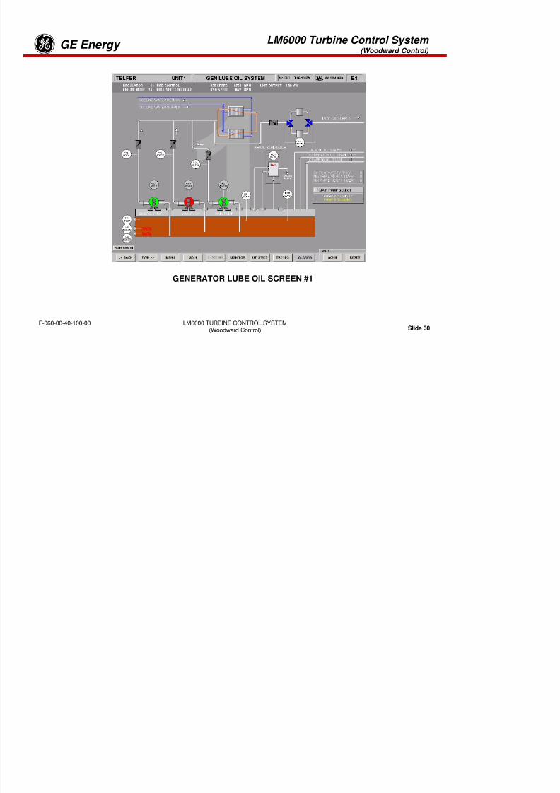
8/18/2019 71777896 - LM6000 Package Familiarization & Operations.pdf
http://slidepdf.com/reader/full/71777896-lm6000-package-familiarization-operationspdf 551/786
LM6000 TURBINE CONTROL SYSTEM(Woodward Control) Slide 28
F-060-00-40-100-00
TURBINE START PERMISSIVE SCREEN
LM6000 Turbine Control System (Woodward Control)
GE Energyg

8/18/2019 71777896 - LM6000 Package Familiarization & Operations.pdf
http://slidepdf.com/reader/full/71777896-lm6000-package-familiarization-operationspdf 552/786
LM6000 TURBINE CONTROL SYSTEM(Woodward Control) Slide 29
F-060-00-40-100-00
CRANK AND WATER WASH PERMISSIVE SCREEN
LM6000 Turbine Control System (Woodward Control)
GE Energyg
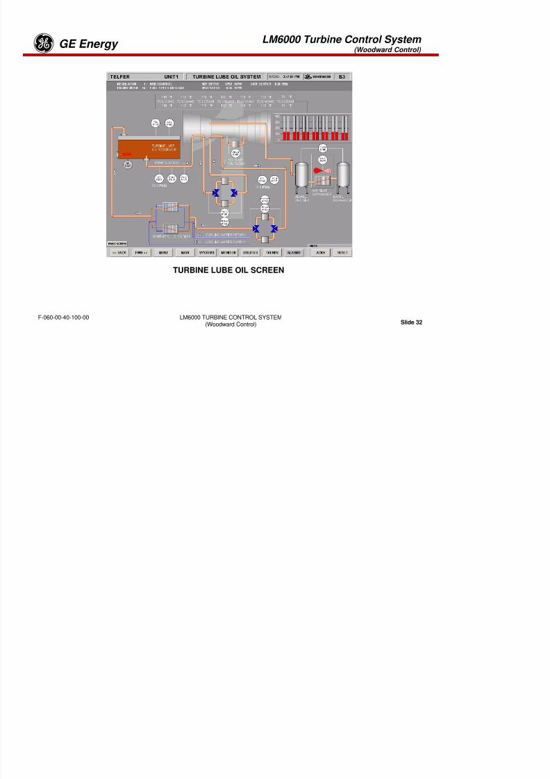
8/18/2019 71777896 - LM6000 Package Familiarization & Operations.pdf
http://slidepdf.com/reader/full/71777896-lm6000-package-familiarization-operationspdf 553/786
LM6000 TURBINE CONTROL SYSTEM(Woodward Control) Slide 30
F-060-00-40-100-00
GENERATOR LUBE OIL SCREEN #1
LM6000 Turbine Control System (Woodward Control)
GE Energyg

8/18/2019 71777896 - LM6000 Package Familiarization & Operations.pdf
http://slidepdf.com/reader/full/71777896-lm6000-package-familiarization-operationspdf 554/786
LM6000 TURBINE CONTROL SYSTEM(Woodward Control) Slide 31
F-060-00-40-100-00
GENERATOR LUBE OIL SCREEN #2
LM6000 Turbine Control System (Woodward Control)
GE Energyg

8/18/2019 71777896 - LM6000 Package Familiarization & Operations.pdf
http://slidepdf.com/reader/full/71777896-lm6000-package-familiarization-operationspdf 555/786
LM6000 TURBINE CONTROL SYSTEM(Woodward Control) Slide 32
F-060-00-40-100-00
TURBINE LUBE OIL SCREEN
LM6000 Turbine Control System (Woodward Control)
GE Energyg

8/18/2019 71777896 - LM6000 Package Familiarization & Operations.pdf
http://slidepdf.com/reader/full/71777896-lm6000-package-familiarization-operationspdf 556/786
LM6000 TURBINE CONTROL SYSTEM(Woodward Control) Slide 33
F-060-00-40-100-00
HYDRAULIC STARTER SCREEN
LM6000 Turbine Control System (Woodward Control)
GE Energyg

8/18/2019 71777896 - LM6000 Package Familiarization & Operations.pdf
http://slidepdf.com/reader/full/71777896-lm6000-package-familiarization-operationspdf 557/786
LM6000 TURBINE CONTROL SYSTEM(Woodward Control) Slide 34
F-060-00-40-100-00
TURBINE OVERVIEW SCREEN
LM6000 Turbine Control System (Woodward Control)
GE Energyg
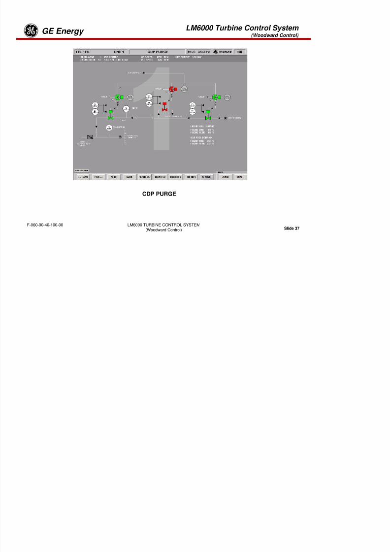
8/18/2019 71777896 - LM6000 Package Familiarization & Operations.pdf
http://slidepdf.com/reader/full/71777896-lm6000-package-familiarization-operationspdf 558/786
LM6000 TURBINE CONTROL SYSTEM(Woodward Control) Slide 35
F-060-00-40-100-00
WATER INJECTION SCREEN
LM6000 Turbine Control System (Woodward Control)
GE Energyg

8/18/2019 71777896 - LM6000 Package Familiarization & Operations.pdf
http://slidepdf.com/reader/full/71777896-lm6000-package-familiarization-operationspdf 559/786
LM6000 TURBINE CONTROL SYSTEM(Woodward Control) Slide 36
F-060-00-40-100-00
FUEL SYSTEM SCREEN
LM6000 Turbine Control System (Woodward Control)
GE Energyg

8/18/2019 71777896 - LM6000 Package Familiarization & Operations.pdf
http://slidepdf.com/reader/full/71777896-lm6000-package-familiarization-operationspdf 560/786
LM6000 TURBINE CONTROL SYSTEM(Woodward Control) Slide 37
F-060-00-40-100-00
CDP PURGE
LM6000 Turbine Control System (Woodward Control)
GE Energyg
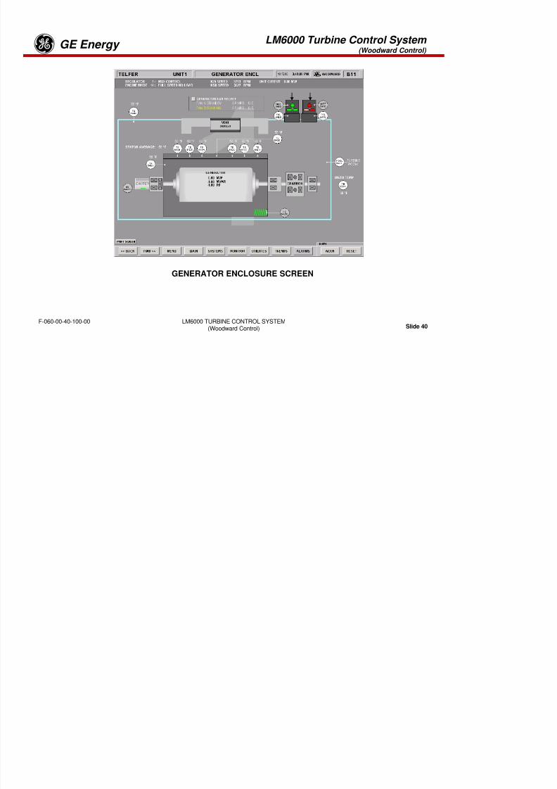
8/18/2019 71777896 - LM6000 Package Familiarization & Operations.pdf
http://slidepdf.com/reader/full/71777896-lm6000-package-familiarization-operationspdf 561/786
LM6000 TURBINE CONTROL SYSTEM(Woodward Control) Slide 38
F-060-00-40-100-00
TURBINE ENCLOSURE VENTILATION SCREEN
LM6000 Turbine Control System (Woodward Control)
GE Energyg

8/18/2019 71777896 - LM6000 Package Familiarization & Operations.pdf
http://slidepdf.com/reader/full/71777896-lm6000-package-familiarization-operationspdf 562/786
LM6000 TURBINE CONTROL SYSTEM(Woodward Control) Slide 39
F-060-00-40-100-00
GEARBOX SCREEN
LM6000 Turbine Control System (Woodward Control)
GE Energyg

8/18/2019 71777896 - LM6000 Package Familiarization & Operations.pdf
http://slidepdf.com/reader/full/71777896-lm6000-package-familiarization-operationspdf 563/786
LM6000 TURBINE CONTROL SYSTEM(Woodward Control) Slide 40
F-060-00-40-100-00
GENERATOR ENCLOSURE SCREEN
LM6000 Turbine Control System (Woodward Control)
GE Energyg
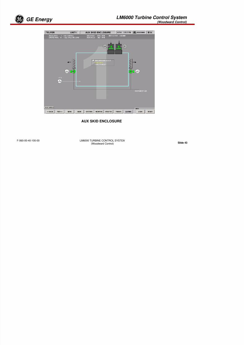
8/18/2019 71777896 - LM6000 Package Familiarization & Operations.pdf
http://slidepdf.com/reader/full/71777896-lm6000-package-familiarization-operationspdf 564/786
LM6000 TURBINE CONTROL SYSTEM(Woodward Control) Slide 41
F-060-00-40-100-00
FIRE PROTECTION SCREEN
LM6000 Turbine Control System (Woodward Control)
GE Energyg

8/18/2019 71777896 - LM6000 Package Familiarization & Operations.pdf
http://slidepdf.com/reader/full/71777896-lm6000-package-familiarization-operationspdf 565/786
LM6000 TURBINE CONTROL SYSTEM(Woodward Control) Slide 42
F-060-00-40-100-00
SPRINT SCREEN
LM6000 Turbine Control System (Woodward Control)
GE Energyg
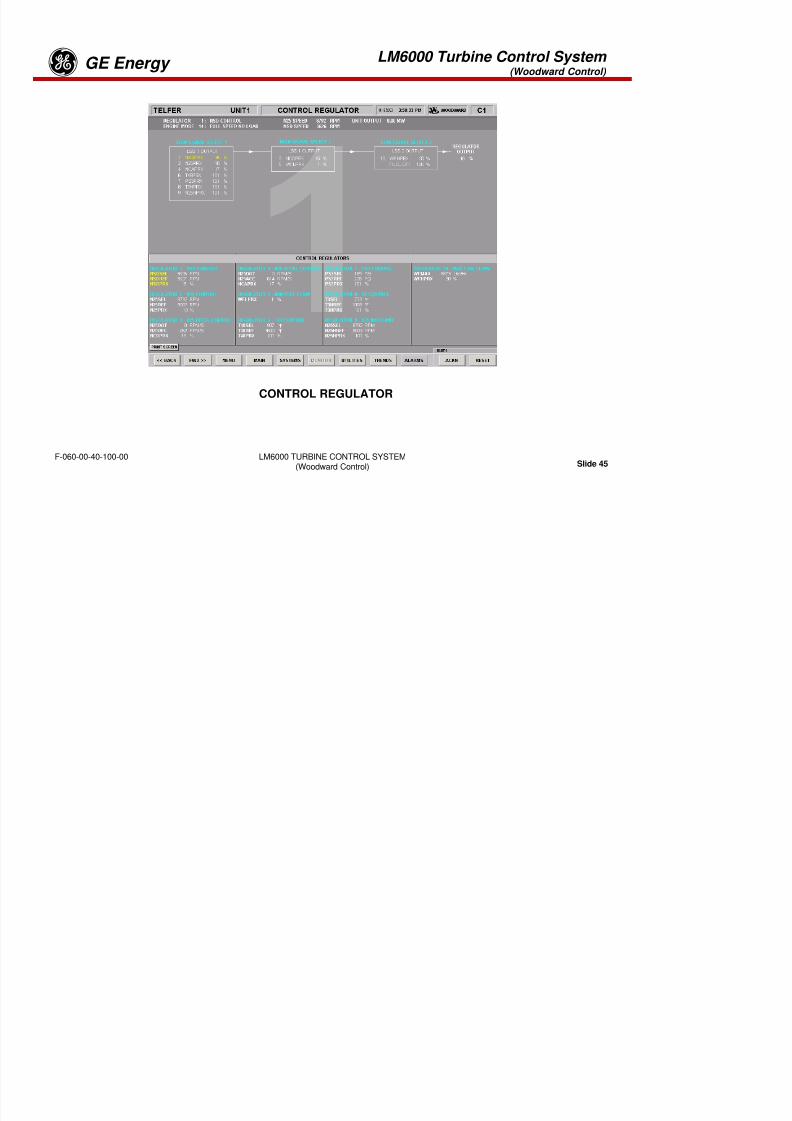
8/18/2019 71777896 - LM6000 Package Familiarization & Operations.pdf
http://slidepdf.com/reader/full/71777896-lm6000-package-familiarization-operationspdf 566/786
LM6000 TURBINE CONTROL SYSTEM(Woodward Control) Slide 43
F-060-00-40-100-00
AUX SKID ENCLOSURE
LM6000 Turbine Control System (Woodward Control)
GE Energyg
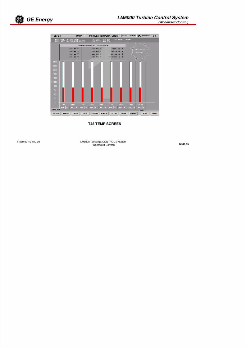
8/18/2019 71777896 - LM6000 Package Familiarization & Operations.pdf
http://slidepdf.com/reader/full/71777896-lm6000-package-familiarization-operationspdf 567/786
LM6000 TURBINE CONTROL SYSTEM(Woodward Control) Slide 44
F-060-00-40-100-00
WATER WASH SCREEN
LM6000 Turbine Control System (Woodward Control)
GE Energyg
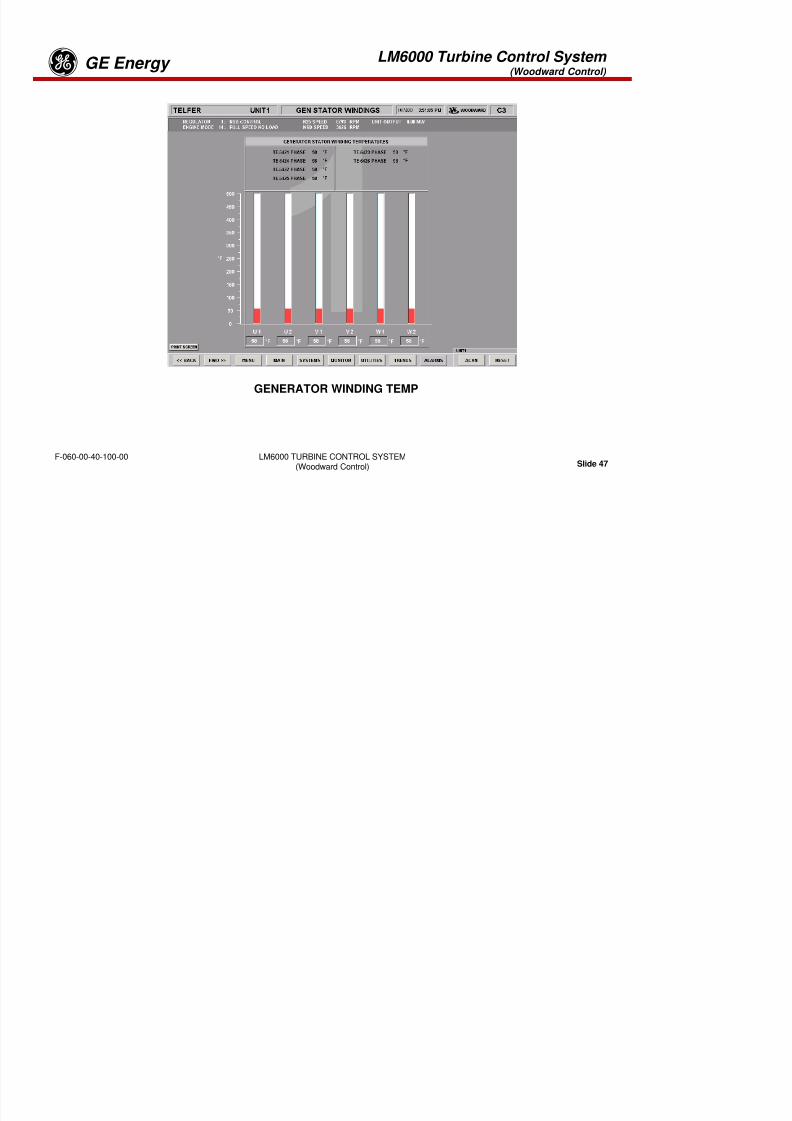
8/18/2019 71777896 - LM6000 Package Familiarization & Operations.pdf
http://slidepdf.com/reader/full/71777896-lm6000-package-familiarization-operationspdf 568/786
LM6000 TURBINE CONTROL SYSTEM(Woodward Control) Slide 45
F-060-00-40-100-00
CONTROL REGULATOR
LM6000 Turbine Control System (Woodward Control)
GE Energyg
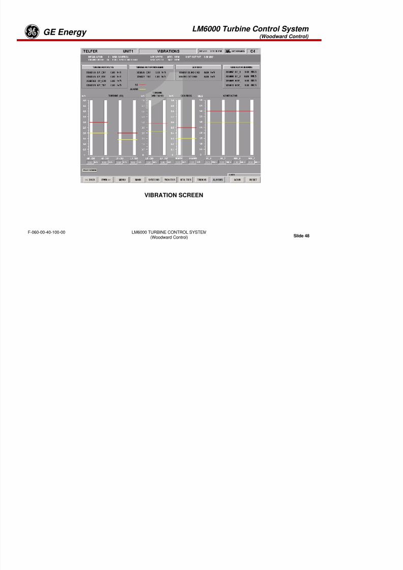
8/18/2019 71777896 - LM6000 Package Familiarization & Operations.pdf
http://slidepdf.com/reader/full/71777896-lm6000-package-familiarization-operationspdf 569/786
LM6000 TURBINE CONTROL SYSTEM(Woodward Control) Slide 46
F-060-00-40-100-00
T48 TEMP SCREEN
LM6000 Turbine Control System (Woodward Control)
GE Energyg

8/18/2019 71777896 - LM6000 Package Familiarization & Operations.pdf
http://slidepdf.com/reader/full/71777896-lm6000-package-familiarization-operationspdf 570/786
LM6000 TURBINE CONTROL SYSTEM(Woodward Control) Slide 47
F-060-00-40-100-00
GENERATOR WINDING TEMP
LM6000 Turbine Control System (Woodward Control)
GE Energyg
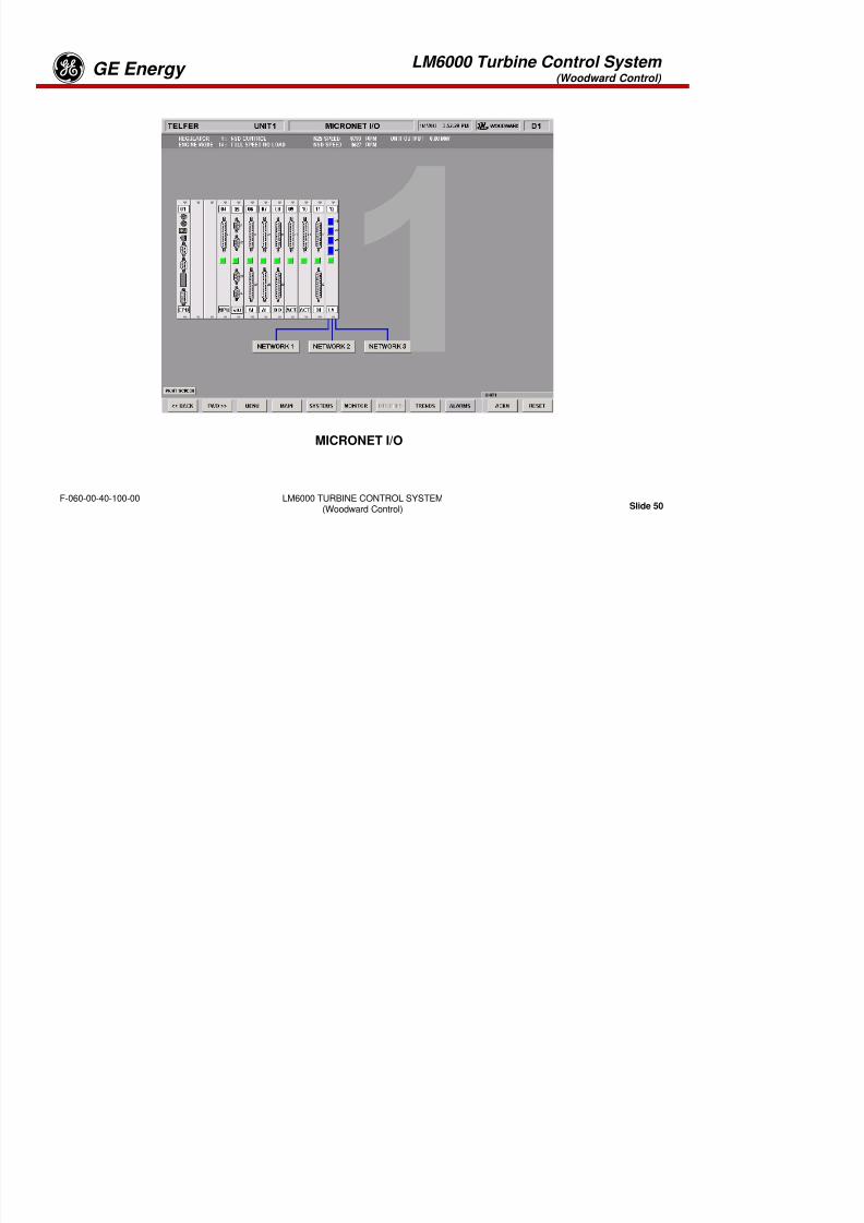
8/18/2019 71777896 - LM6000 Package Familiarization & Operations.pdf
http://slidepdf.com/reader/full/71777896-lm6000-package-familiarization-operationspdf 571/786
LM6000 TURBINE CONTROL SYSTEM(Woodward Control) Slide 48
F-060-00-40-100-00
VIBRATION SCREEN
LM6000 Turbine Control System (Woodward Control)
GE Energyg
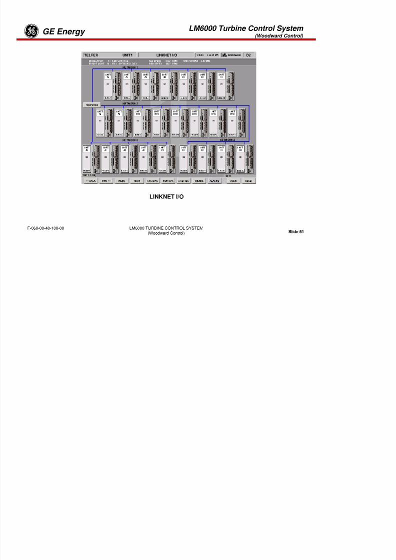
8/18/2019 71777896 - LM6000 Package Familiarization & Operations.pdf
http://slidepdf.com/reader/full/71777896-lm6000-package-familiarization-operationspdf 572/786
LM6000 TURBINE CONTROL SYSTEM(Woodward Control) Slide 49
F-060-00-40-100-00
OPERTIONAL DATA
LM6000 Turbine Control System (Woodward Control)
GE Energyg
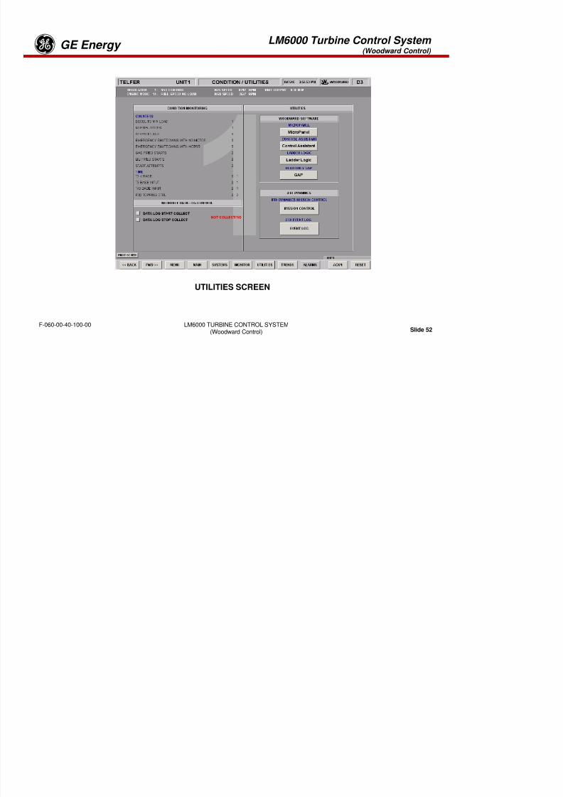
8/18/2019 71777896 - LM6000 Package Familiarization & Operations.pdf
http://slidepdf.com/reader/full/71777896-lm6000-package-familiarization-operationspdf 573/786
LM6000 TURBINE CONTROL SYSTEM(Woodward Control) Slide 50
F-060-00-40-100-00
MICRONET I/O
LM6000 Turbine Control System (Woodward Control)
GE Energyg

8/18/2019 71777896 - LM6000 Package Familiarization & Operations.pdf
http://slidepdf.com/reader/full/71777896-lm6000-package-familiarization-operationspdf 574/786
LM6000 TURBINE CONTROL SYSTEM(Woodward Control) Slide 51
F-060-00-40-100-00
LINKNET I/O
LM6000 Turbine Control System (Woodward Control)
GE Energyg

8/18/2019 71777896 - LM6000 Package Familiarization & Operations.pdf
http://slidepdf.com/reader/full/71777896-lm6000-package-familiarization-operationspdf 575/786
LM6000 TURBINE CONTROL SYSTEM(Woodward Control) Slide 52
F-060-00-40-100-00
UTILITIES SCREEN
LM6000 Turbine Control System (Woodward Control)
GE Energyg
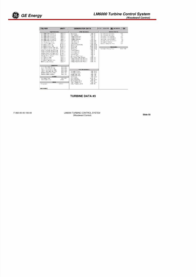
8/18/2019 71777896 - LM6000 Package Familiarization & Operations.pdf
http://slidepdf.com/reader/full/71777896-lm6000-package-familiarization-operationspdf 576/786
LM6000 TURBINE CONTROL SYSTEM(Woodward Control) Slide 53
F-060-00-40-100-00
TURBINE DATA #1
LM6000 Turbine Control System (Woodward Control)
GE Energyg
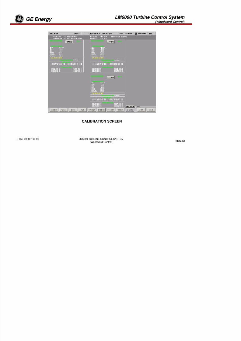
8/18/2019 71777896 - LM6000 Package Familiarization & Operations.pdf
http://slidepdf.com/reader/full/71777896-lm6000-package-familiarization-operationspdf 577/786
LM6000 TURBINE CONTROL SYSTEM(Woodward Control) Slide 54
F-060-00-40-100-00
TURBINE DATA #2
LM6000 Turbine Control System (Woodward Control)
GE Energyg
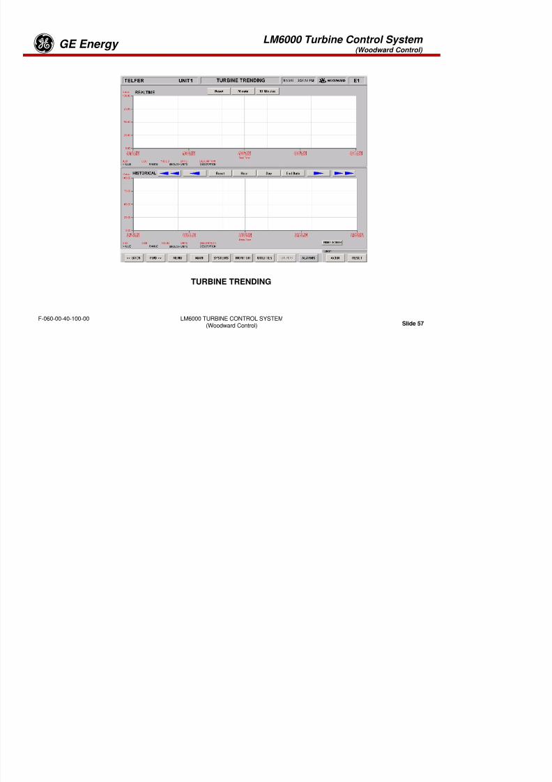
8/18/2019 71777896 - LM6000 Package Familiarization & Operations.pdf
http://slidepdf.com/reader/full/71777896-lm6000-package-familiarization-operationspdf 578/786
LM6000 TURBINE CONTROL SYSTEM(Woodward Control) Slide 55
F-060-00-40-100-00
TURBINE DATA #3
LM6000 Turbine Control System (Woodward Control)
GE Energyg
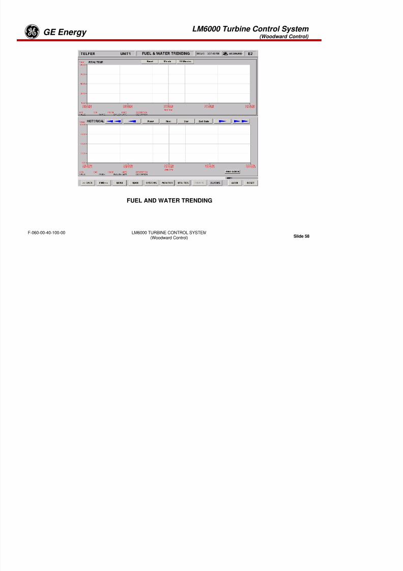
8/18/2019 71777896 - LM6000 Package Familiarization & Operations.pdf
http://slidepdf.com/reader/full/71777896-lm6000-package-familiarization-operationspdf 579/786
LM6000 TURBINE CONTROL SYSTEM(Woodward Control) Slide 56
F-060-00-40-100-00
CALIBRATION SCREEN
LM6000 Turbine Control System (Woodward Control)
GE Energyg

8/18/2019 71777896 - LM6000 Package Familiarization & Operations.pdf
http://slidepdf.com/reader/full/71777896-lm6000-package-familiarization-operationspdf 580/786
LM6000 TURBINE CONTROL SYSTEM(Woodward Control) Slide 57
F-060-00-40-100-00
TURBINE TRENDING
LM6000 Turbine Control System (Woodward Control)
GE Energyg
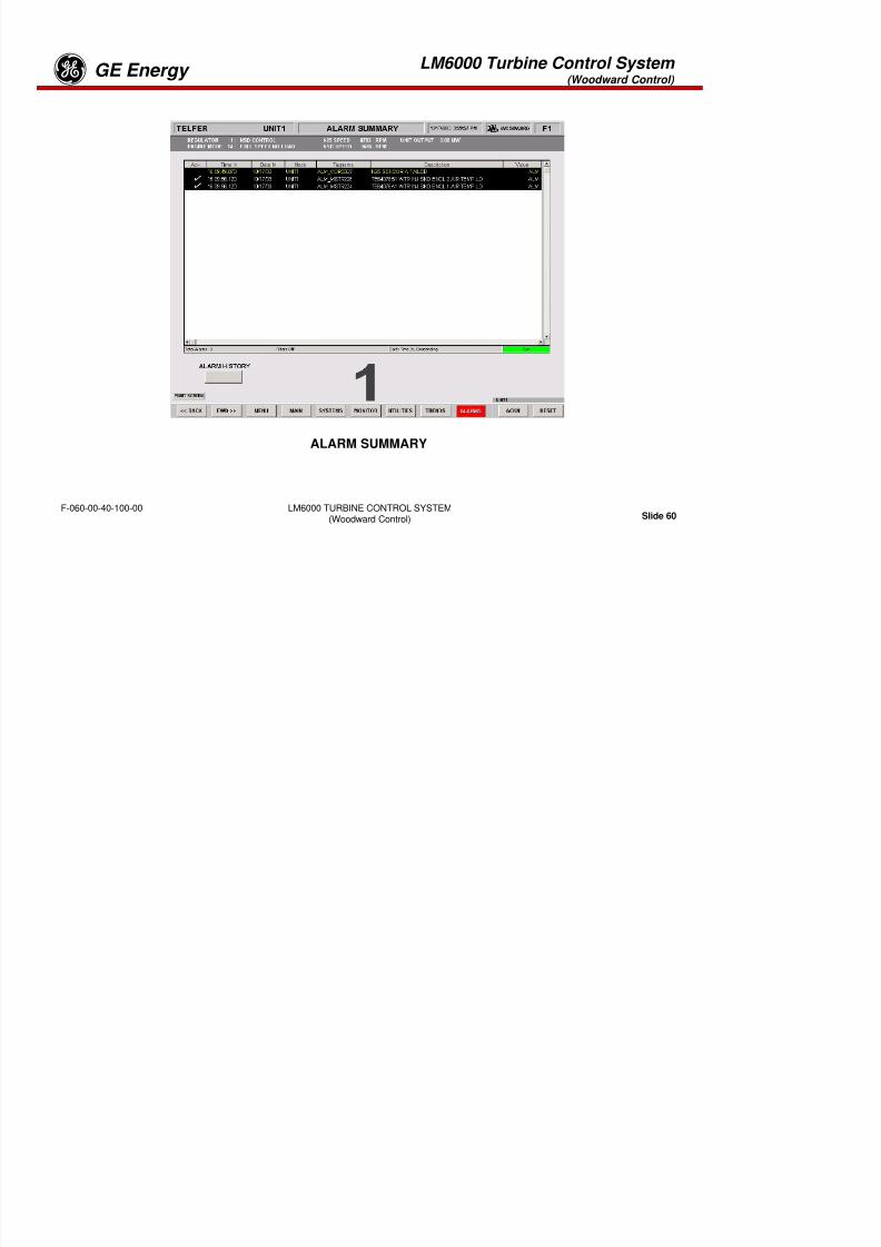
8/18/2019 71777896 - LM6000 Package Familiarization & Operations.pdf
http://slidepdf.com/reader/full/71777896-lm6000-package-familiarization-operationspdf 581/786
LM6000 TURBINE CONTROL SYSTEM(Woodward Control) Slide 58
F-060-00-40-100-00
FUEL AND WATER TRENDING

8/18/2019 71777896 - LM6000 Package Familiarization & Operations.pdf
http://slidepdf.com/reader/full/71777896-lm6000-package-familiarization-operationspdf 582/786
LM6000 Turbine Control System (Woodward Control)
GE Energyg

8/18/2019 71777896 - LM6000 Package Familiarization & Operations.pdf
http://slidepdf.com/reader/full/71777896-lm6000-package-familiarization-operationspdf 583/786
LM6000 TURBINE CONTROL SYSTEM(Woodward Control) Slide 60
F-060-00-40-100-00
ALARM SUMMARY
LM6000 Turbine Control System (Woodward Control)
GE Energyg

8/18/2019 71777896 - LM6000 Package Familiarization & Operations.pdf
http://slidepdf.com/reader/full/71777896-lm6000-package-familiarization-operationspdf 584/786
LM6000 TURBINE CONTROL SYSTEM(Woodward Control) Slide 61
F-060-00-40-100-00
ABORT STARTS #1
LM6000 Turbine Control System (Woodward Control)
GE Energyg

8/18/2019 71777896 - LM6000 Package Familiarization & Operations.pdf
http://slidepdf.com/reader/full/71777896-lm6000-package-familiarization-operationspdf 585/786
LM6000 TURBINE CONTROL SYSTEM(Woodward Control) Slide 62
F-060-00-40-100-00
ABORT STARTS #2
LM6000 Turbine Control System (Woodward Control)
GE Energyg

8/18/2019 71777896 - LM6000 Package Familiarization & Operations.pdf
http://slidepdf.com/reader/full/71777896-lm6000-package-familiarization-operationspdf 586/786
LM6000 TURBINE CONTROL SYSTEM(Woodward Control) Slide 63
F-060-00-40-100-00
EMERGENCY SHUTDOWN WITH MOTOR
LM6000 Turbine Control System (Woodward Control)
GE Energyg
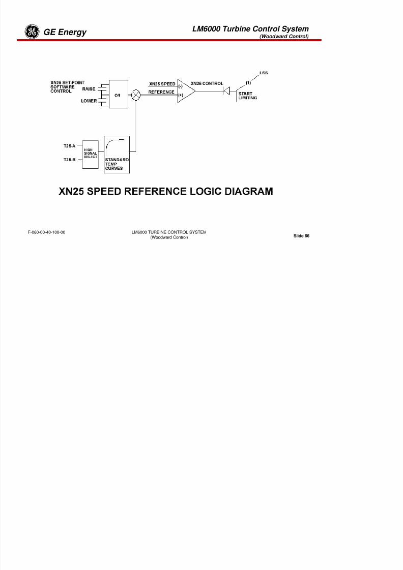
8/18/2019 71777896 - LM6000 Package Familiarization & Operations.pdf
http://slidepdf.com/reader/full/71777896-lm6000-package-familiarization-operationspdf 587/786
LM6000 TURBINE CONTROL SYSTEM(Woodward Control) Slide 64
F-060-00-40-100-00
EMERGENCY SHUTDOWN WITH NO MOTOR
LM6000 Turbine Control System (Woodward Control)
GE Energyg
FUEL CONTROL SYSTEM SCHEMATIC WALK THROUGH
The fuel valve position is driven by the output of the two low signal select (LSS) buses, whichever islowest. For example, if the start limiting signal at LSS (2) is at a lower value than the output of bus (1) orthe deceleration limit or fuel flow limiting signal into bus (2), the start limiting signal will control the fuelvalve. As the start limiting signal increases, one of the other inputs will control the fuel control valveposition.
Typical of the inputs to LSS bus (1) is the XN25 control signal. The XN25 speed and reference signalsare illustrated as inputs to an operational amplifier configured as a comparator The comparator output
8/18/2019 71777896 - LM6000 Package Familiarization & Operations.pdf
http://slidepdf.com/reader/full/71777896-lm6000-package-familiarization-operationspdf 588/786
LM6000 TURBINE CONTROL SYSTEM(Woodward Control) Slide 65
F-060-00-40-100-00
are illustrated as inputs to an operational amplifier configured as a comparator. The comparator outputwill remain positive unless the XN25 speed signal increases above the reference value.
System sequencing logic, under operator direction, establishes the start limiting and the XN25 andXNSD reference signals as biased by safety conditions. Limiting inputs from T48, PS3, and T3 controlfuel to prevent engine damage, compressor stalls, or flameout conditions. The limiting inputs are derivedfrom transfer functions based upon engine operational design parameters.
LM6000 Turbine Control System (Woodward Control)
GE Energyg

8/18/2019 71777896 - LM6000 Package Familiarization & Operations.pdf
http://slidepdf.com/reader/full/71777896-lm6000-package-familiarization-operationspdf 589/786
LM6000 TURBINE CONTROL SYSTEM(Woodward Control) Slide 66
F-060-00-40-100-00
LM6000 Turbine Control System (Woodward Control)
GE EnergygXN25 SPEED REFERENCE LOGIC DIAGRAM
Voltage from the XN25 reference ramp is raised or lowered under software control. High-
pressurecompressor discharge temperature is compensated for standard temperature variations (T2 = 59° F [15°C]) and applied as a bias to the reference ramp output, to obtain the XN25 reference input value.
8/18/2019 71777896 - LM6000 Package Familiarization & Operations.pdf
http://slidepdf.com/reader/full/71777896-lm6000-package-familiarization-operationspdf 590/786
LM6000 TURBINE CONTROL SYSTEM(Woodward Control) Slide 67
F-060-00-40-100-00
LM6000 Turbine Control System (Woodward Control)
GE Energyg
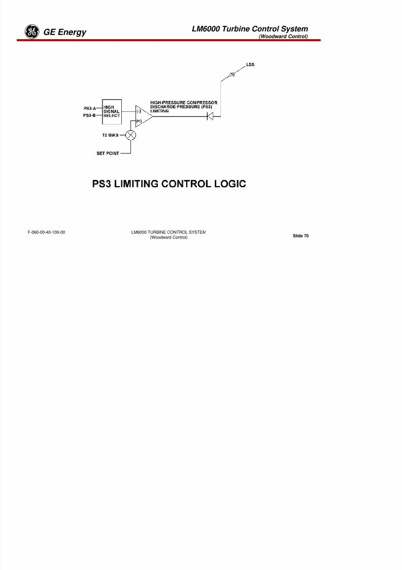
8/18/2019 71777896 - LM6000 Package Familiarization & Operations.pdf
http://slidepdf.com/reader/full/71777896-lm6000-package-familiarization-operationspdf 591/786
LM6000 TURBINE CONTROL SYSTEM(Woodward Control) Slide 68
F-060-00-40-100-00
LM6000 Turbine Control System (Woodward Control)
GE EnergygXNSD SPEED REFERENCE LOGIC DIAGRAM
Two modes of control are provided: isochronous or parallel mode. In the isochronous mode, XNSD speedis maintained at 3600 rpm, with allowance for droop as load increases. In the parallel mode, powerobtained from load current and voltage is summed with the output of an XNSD reference ramp. Theresulting XNSD reference is stabilized when loading is driven to equal the set point reference. Set pointcontrol is established manually or automatically from operator-loading selections. (See Sequencing Logicsection.)

8/18/2019 71777896 - LM6000 Package Familiarization & Operations.pdf
http://slidepdf.com/reader/full/71777896-lm6000-package-familiarization-operationspdf 592/786
LM6000 TURBINE CONTROL SYSTEM(Woodward Control) Slide 69
F-060-00-40-100-00
LM6000 Turbine Control System (Woodward Control)
GE Energyg
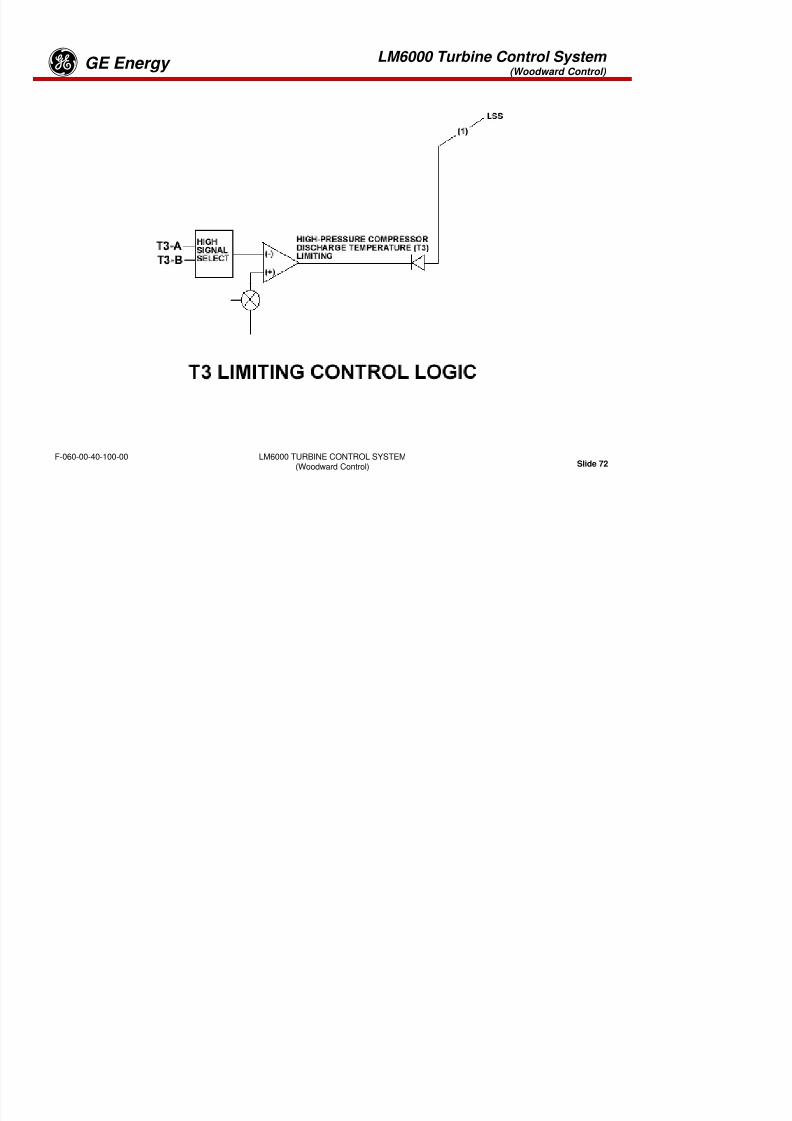
8/18/2019 71777896 - LM6000 Package Familiarization & Operations.pdf
http://slidepdf.com/reader/full/71777896-lm6000-package-familiarization-operationspdf 593/786
LM6000 TURBINE CONTROL SYSTEM(Woodward Control) Slide 70
F-060-00-40-100-00
LM6000 Turbine Control System (Woodward Control)
GE Energyg
PS3 LIMITING CONTROL LOGIC
The higher of the two PS3 sensors (A or B) is compared with the PS3 set point as biased by LPC inlettemperature T3. The influence of the T2 bias at values below
48° F (9° C) is negative, whereas at temperatures above 48° F, the T2 bias is positive. The bias isimplemented to prevent engine damage caused by high PS3 values and to improve performance at higherHPC inlet temperatures.
8/18/2019 71777896 - LM6000 Package Familiarization & Operations.pdf
http://slidepdf.com/reader/full/71777896-lm6000-package-familiarization-operationspdf 594/786
LM6000 TURBINE CONTROL SYSTEM(Woodward Control) Slide 71
F-060-00-40-100-00
LM6000 Turbine Control System (Woodward Control)
GE Energyg
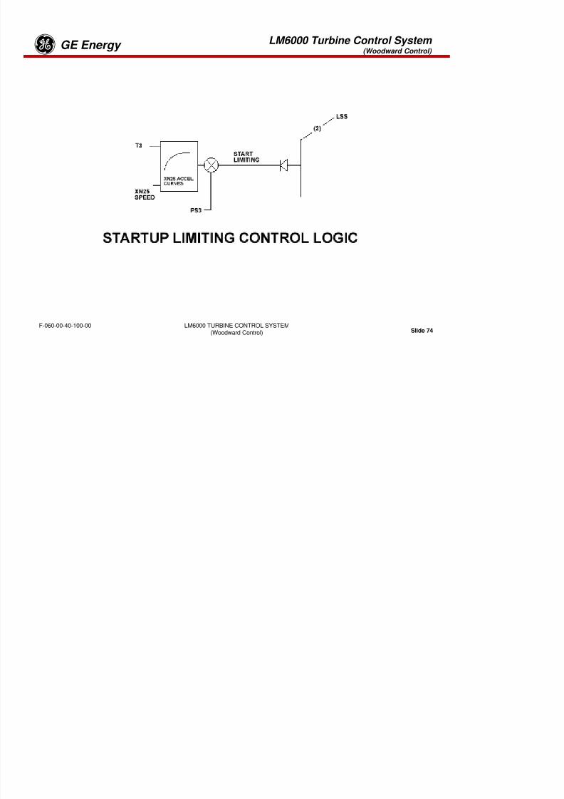
8/18/2019 71777896 - LM6000 Package Familiarization & Operations.pdf
http://slidepdf.com/reader/full/71777896-lm6000-package-familiarization-operationspdf 595/786
LM6000 TURBINE CONTROL SYSTEM(Woodward Control) Slide 72
F-060-00-40-100-00
LM6000 Turbine Control System (Woodward Control)
GE Energyg
T3 LIMITING CONTROL LOGIC
The higher of the two T3 sensors (A or B) is compared with the T3 set point, as biased by the LPC inlettemperature T2. The influence of the T2 bias prevents T3 from exceeding values that would affect enginereliability. As T2 decreases, T3 is limited to lower values because of the air mass increase at lowertemperatures.
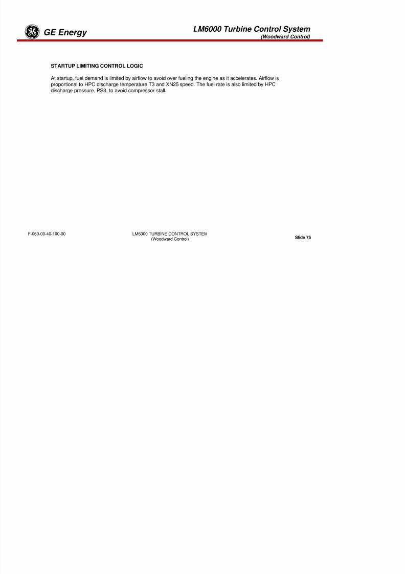
8/18/2019 71777896 - LM6000 Package Familiarization & Operations.pdf
http://slidepdf.com/reader/full/71777896-lm6000-package-familiarization-operationspdf 596/786
LM6000 TURBINE CONTROL SYSTEM(Woodward Control) Slide 73
F-060-00-40-100-00
LM6000 Turbine Control System (Woodward Control)
GE Energyg
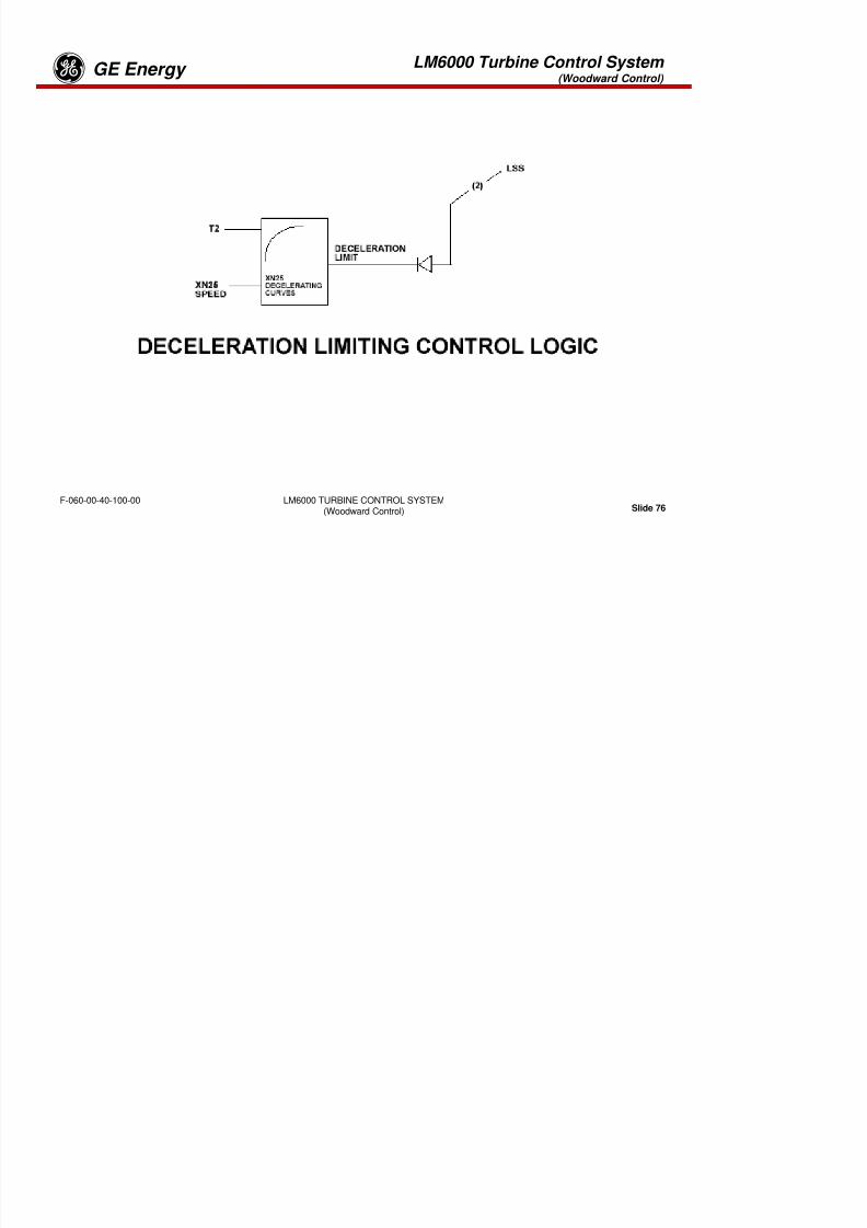
8/18/2019 71777896 - LM6000 Package Familiarization & Operations.pdf
http://slidepdf.com/reader/full/71777896-lm6000-package-familiarization-operationspdf 597/786
LM6000 TURBINE CONTROL SYSTEM(Woodward Control) Slide 74
F-060-00-40-100-00
LM6000 Turbine Control System (Woodward Control)
GE Energyg
STARTUP LIMITING CONTROL LOGIC
At startup, fuel demand is limited by airflow to avoid over fueling the engine as it accelerates. Airflow isproportional to HPC discharge temperature T3 and XN25 speed. The fuel rate is also limited by HPCdischarge pressure, PS3, to avoid compressor stall.

8/18/2019 71777896 - LM6000 Package Familiarization & Operations.pdf
http://slidepdf.com/reader/full/71777896-lm6000-package-familiarization-operationspdf 598/786
LM6000 TURBINE CONTROL SYSTEM(Woodward Control) Slide 75
F-060-00-40-100-00
LM6000 Turbine Control System (Woodward Control)
GE Energyg
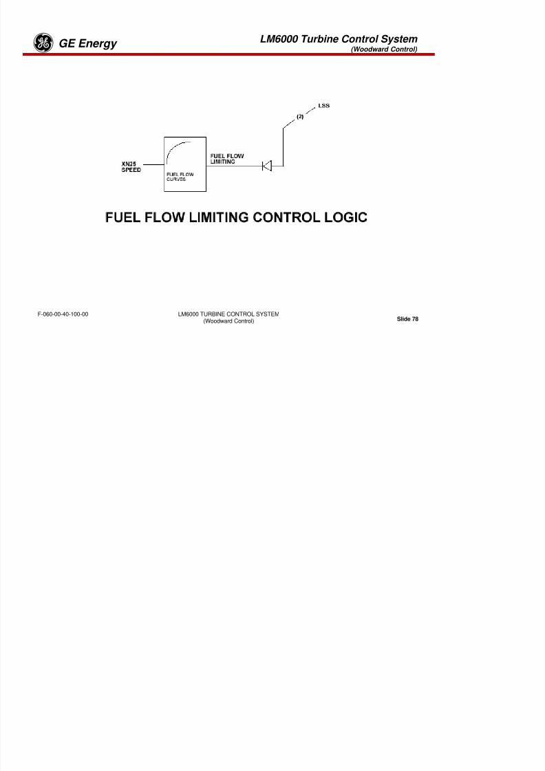
8/18/2019 71777896 - LM6000 Package Familiarization & Operations.pdf
http://slidepdf.com/reader/full/71777896-lm6000-package-familiarization-operationspdf 599/786
LM6000 TURBINE CONTROL SYSTEM(Woodward Control) Slide 76
F-060-00-40-100-00
LM6000 Turbine Control System (Woodward Control)
GE Energyg
DECELERATION LIMITING CONTROL LOGIC
During deceleration, reduction of fuel is limited to avoid flameout. The rate of fuel limiting is proportional toairflow, T2 (LPC inlet temperature), and XN25 speed.

8/18/2019 71777896 - LM6000 Package Familiarization & Operations.pdf
http://slidepdf.com/reader/full/71777896-lm6000-package-familiarization-operationspdf 600/786
LM6000 TURBINE CONTROL SYSTEM(Woodward Control) Slide 77
F-060-00-40-100-00
LM6000 Turbine Control System (Woodward Control)
GE Energyg

8/18/2019 71777896 - LM6000 Package Familiarization & Operations.pdf
http://slidepdf.com/reader/full/71777896-lm6000-package-familiarization-operationspdf 601/786
LM6000 TURBINE CONTROL SYSTEM(Woodward Control) Slide 78
F-060-00-40-100-00
LM6000 Turbine Control System (Woodward Control)
GE Energyg
FUEL FLOW LIMITING CONTROL LOGIC
Fuel flow limiting is initiated in the event engine speed does not increase with fuel flow. This is a backupfunction that assumes that regardless of ambient temperature and pressure conditions, fuel flow shouldnot exceed a predictable quantity versus HPC speed.

8/18/2019 71777896 - LM6000 Package Familiarization & Operations.pdf
http://slidepdf.com/reader/full/71777896-lm6000-package-familiarization-operationspdf 602/786
LM6000 TURBINE CONTROL SYSTEM(Woodward Control) Slide 79
F-060-00-40-100-00
Tab 17

8/18/2019 71777896 - LM6000 Package Familiarization & Operations.pdf
http://slidepdf.com/reader/full/71777896-lm6000-package-familiarization-operationspdf 603/786
LM6000 Sequences GE Energy
LM6000 Sequences

8/18/2019 71777896 - LM6000 Package Familiarization & Operations.pdf
http://slidepdf.com/reader/full/71777896-lm6000-package-familiarization-operationspdf 604/786
Slide 1LM6000 SequencesF-060-00-50-000-00
LM6000 Sequences GE Energy
Objectives:
Upon completion of this section the student should:
Be familiar with start permissives
Understand normal start up sequence and shutdown sequence
Be familiar with the various shutdown sequences
8/18/2019 71777896 - LM6000 Package Familiarization & Operations.pdf
http://slidepdf.com/reader/full/71777896-lm6000-package-familiarization-operationspdf 605/786
Slide 2LM6000 SequencesF-060-00-50-000-00
LM6000 Sequences GE Energy
Pre-Operation Procedures
Applying Power During Downtime
Pre-Start Inspections
Mechanical

8/18/2019 71777896 - LM6000 Package Familiarization & Operations.pdf
http://slidepdf.com/reader/full/71777896-lm6000-package-familiarization-operationspdf 606/786
Slide 3LM6000 SequencesF-060-00-50-000-00
Mechanical
•Fuel System
•Fire/Gas Detection System
•Control System Power-Up
•Alarm Acknowledge and Reset
LM6000 Sequences GE Energy
GTG Set Operation
GTG set operation consists of the manual steps required in the preoperating
procedures plus normal operation under program control. Performance is as follows:
1. Perform the preoperation procedures to prepare the system for operation under
program control.
2. At the operator interface, familiarize yourself with the specific unit data, overview,
alarm- and user-designed displays for each unit, and become familiar with the basicoperating program sequence for each unit.
3. In particular, become familiar with the main display and the other overview displays
used for control or adjustments to operation.
8/18/2019 71777896 - LM6000 Package Familiarization & Operations.pdf
http://slidepdf.com/reader/full/71777896-lm6000-package-familiarization-operationspdf 607/786
Slide 4LM6000 SequencesF-060-00-50-000-00
used for control or adjustments to operation.
4. When thoroughly familiar with the above, select the main display and execute the
commands required for the operation desired.
LM6000 Sequences GE Energy
PREOPERATION PROCEDURES
Applying Alternating-Current Power During Downtime
Alternating-current (AC) power (normally commercial power) is required for certain
functions, such as lighting and heating, and for maintenance purposes while theturbine generator is not running. To apply AC power for specific power needs
during downtime, or in preparation for startup, perform the applicable portions of
the following procedure.
1. Ensure that no repair work is being performed on bus or connected circuitry.
2 Cl tilit i it b k t l AC t ti b

8/18/2019 71777896 - LM6000 Package Familiarization & Operations.pdf
http://slidepdf.com/reader/full/71777896-lm6000-package-familiarization-operationspdf 608/786
Slide 5LM6000 SequencesF-060-00-50-000-00
2. Close utility circuit breaker to apply AC power to cogeneration bus.
3. Close utility circuit breaker to apply AC power to the cogeneration bus.
4. Set main circuit breaker to On position.5. Set lighting and power distribution cubicle circuit breaker handle to On position.
6. Turn on lights and systems, as required, on lighting and power distribution panel,
and turn on space heaters as dictated by ambient temperature conditions.
7. Check oil levels in turbine and generator lube oil reservoirs. Add oil as
necessary to restore specified levels. Use only approved oils for turbine and
generator lube oil systems.
LM6000 Sequences GE Energy
Applying Alternating-Current Power During Downtime
Check fluid level in hydraulic start unit reservoir. Add fluid as necessary.
Set cubicle circuit breaker handles to On position for all lubrication and hydraulic oil
tank heaters, space heaters, and generator stator core heater.
Check that lubricating oil temperatures are more than 70 °F (21 °C).
PRESTART INSPECTIONSThis procedure consists of a series of mechanical inspections and corrections, asnecessary, to ensure the GTG set is in condition for safe and effective startup and
operation.

8/18/2019 71777896 - LM6000 Package Familiarization & Operations.pdf
http://slidepdf.com/reader/full/71777896-lm6000-package-familiarization-operationspdf 609/786
Slide 6LM6000 SequencesF-060-00-50-000-00
p
General Mechanical Inspections
If maintenance has been performed on the inlet air filter, replace panel filters or
barrier filter elements that were removed for maintenance. If maintenance has also
been performed on the air filter or turbine air inlet, obtain access to inlet plenum andinspect for cleanliness. Remove any foreign objects or debris. Ensure all filter
house doors are securely closed.
LM6000 Sequences GE Energy
Because of variations in operating conditions, as well as differences in hardware,“normal” indicator readings vary between GTG sets. For this reason, it is important
that the equipment be monitored frequently during the first 30 – 90 days of operationso that performance trends can be recorded and maintenance requirementspredicted. Toward this end, regular monitoring intervals should be set up for
recording all instrument readings while the generator is in operation. These datashould be continuously compared to the established trend, and adjustments should
be made as necessary to ensure that readings stay within acceptable limits and the
generator rating is not exceeded.
OPERATING PROCEDURE SELECTION
8/18/2019 71777896 - LM6000 Package Familiarization & Operations.pdf
http://slidepdf.com/reader/full/71777896-lm6000-package-familiarization-operationspdf 610/786
Slide 7LM6000 SequencesF-060-00-50-000-00
Insofar as is practical, these operating procedures are presented in a progressive
sequence from preparation for startup through shutdown. In addition, service and
maintenance functions are deferred to O&M section SP-M016 , ControlSystem/Operator Interfaces.
LM6000 Sequences GE Energy
Fire Suppression and Gas Detection System Inspection:
1. Verify that optical flame detectors are aimed in the desired direction, with a
clear field of view.2. Check maintenance records to verify that detectors have been cali-brated
and tested according to the maintenance schedule.
3 Check thermal spot detectors for clean undamaged probes
FUEL SYSTEMS CHECKS
Verify that fuel supply pressure is between 655 and 720 psig (4517 and 4964kPaG) at the source (gas fuel) and 1200 and 1340 psig (8.3 and 9.2 kPaG) at the
source (liquid fuel).

8/18/2019 71777896 - LM6000 Package Familiarization & Operations.pdf
http://slidepdf.com/reader/full/71777896-lm6000-package-familiarization-operationspdf 611/786
Slide 8LM6000 SequencesF-060-00-50-000-00
3. Check thermal spot detectors for clean, undamaged probes.
4. Verify that detectors have been properly calibrated and tested.
5. Check combustible gas detector sensors to ensure that screens are clean.6. Check mainte-nance records to verify sen-sors- have been calibrated and
tested according to the maintenance schedule.
LM6000 Sequences GE Energy
7. Verify that fire extinguisher nozzles are free of obstructions or corrosion.
8. Check pop-up indicator on end of each manifold to ensure that extinguishant
has not been discharged from either cylinder bank.
9. Check maintenance records to verify that cylinders have been weighed orcharged within the last 6 months.
10. After closing enclosure, ensure manual block valves are in the open position.
11. Ensure that the fire and gas detection panel is clear of all alarms andshutdowns.
Fire Suppression and Gas Detection System Inspection (cont.):
8/18/2019 71777896 - LM6000 Package Familiarization & Operations.pdf
http://slidepdf.com/reader/full/71777896-lm6000-package-familiarization-operationspdf 612/786
Slide 9LM6000 SequencesF-060-00-50-000-00
LM6000 Sequences GE Energy
Mark VIe
1. Verify that all power-discon-nect handles are in closed position.
2. Verify that all Hand-Off-Auto switches are in Auto position.
3. At battery location, verify that AC supply and output safety disconnects from allbattery systems are closed.
4. At battery room, verify that circuit breakers on battery chargers are closed.
5 Close molded switches SW24C and SW24F to apply 24-VDC
INITIAL POWER-UP PROCEDURE
To apply AC and direct-current (DC) power to the various systems of the
GTG set in preparation for startup, perform the following steps:
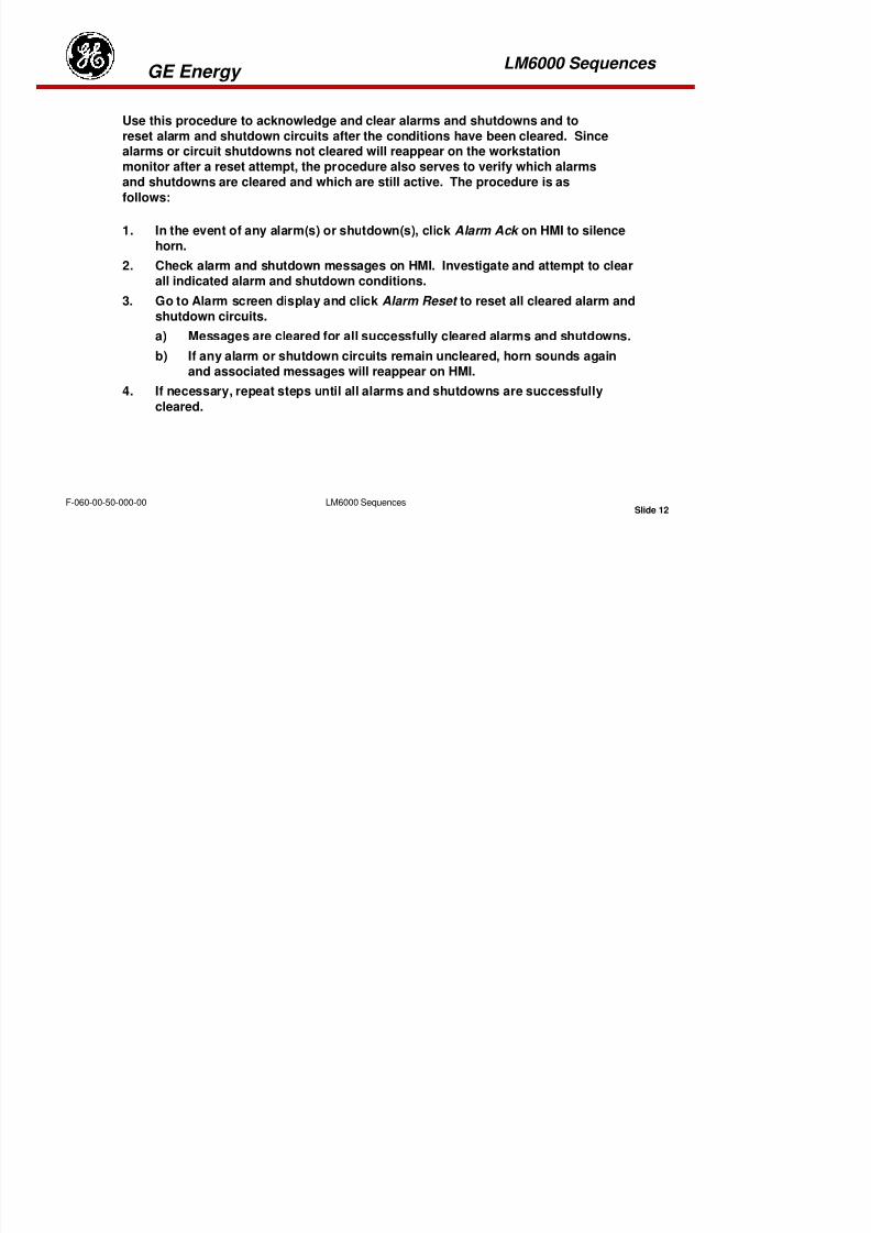
8/18/2019 71777896 - LM6000 Package Familiarization & Operations.pdf
http://slidepdf.com/reader/full/71777896-lm6000-package-familiarization-operationspdf 613/786
Slide 10LM6000 SequencesF-060-00-50-000-00
5. Close molded switches SW24C and SW24F to apply 24-VDC.
6. Verify that the TCP Fire Suppression and Gas Detection System central control unit
is operating and no faults are indicated.
7. Close molded switch SW125C and SW125M to apply 125-VDC.
LM6000 Sequences GE Energy
8. Verify that the Mark VIe is powered up.9. When auto-programming is complete, observe all modules in mark VIe
enclosure. Extinguish red indicators on all modules.
10. Click Alarm Ack , then Alarm Reset on the HMI.
a) If horn sounds, click Alarm Ack to silence horn.
b) Investigate and clear activated alarms or shutdowns as indicated onmonitor, using procedure described in “Alarm Acknowledge and
Reset” section to acknowledge and reset alarms after clearing.
c) When all shutdowns and start permissives are cleared, READY FOR
START th it
INITIAL POWER-UP PROCEDURE (cont):

8/18/2019 71777896 - LM6000 Package Familiarization & Operations.pdf
http://slidepdf.com/reader/full/71777896-lm6000-package-familiarization-operationspdf 614/786
Slide 11LM6000 SequencesF-060-00-50-000-00
START message appears on the monitor.
ALARM ACKNOWLEDGE AND RESET
Note: Alarm and Trip settings are provided in GE Energy drawings XXX143
and XXX146
LM6000 Sequences GE Energy
1. In the event of any alarm(s) or shutdown(s), click Alarm Ack on HMI to silence
horn.2. Check alarm and shutdown messages on HMI. Investigate and attempt to clear
all indicated alarm and shutdown conditions.
3. Go to Alarm screen display and click Alarm Reset to reset all cleared alarm and
Use this procedure to acknowledge and clear alarms and shutdowns and to
reset alarm and shutdown circuits after the conditions have been cleared. Since
alarms or circuit shutdowns not cleared will reappear on the workstationmonitor after a reset attempt, the procedure also serves to verify which alarms
and shutdowns are cleared and which are still active. The procedure is as
follows:

8/18/2019 71777896 - LM6000 Package Familiarization & Operations.pdf
http://slidepdf.com/reader/full/71777896-lm6000-package-familiarization-operationspdf 615/786
Slide 12LM6000 SequencesF-060-00-50-000-00
shutdown circuits.
a) Messages are cleared for all successfully cleared alarms and shutdowns.
b) If any alarm or shutdown circuits remain uncleared, horn sounds again
and associated messages will reappear on HMI.
4. If necessary, repeat steps until all alarms and shutdowns are successfully
cleared.
LM6000 Sequences GE Energy
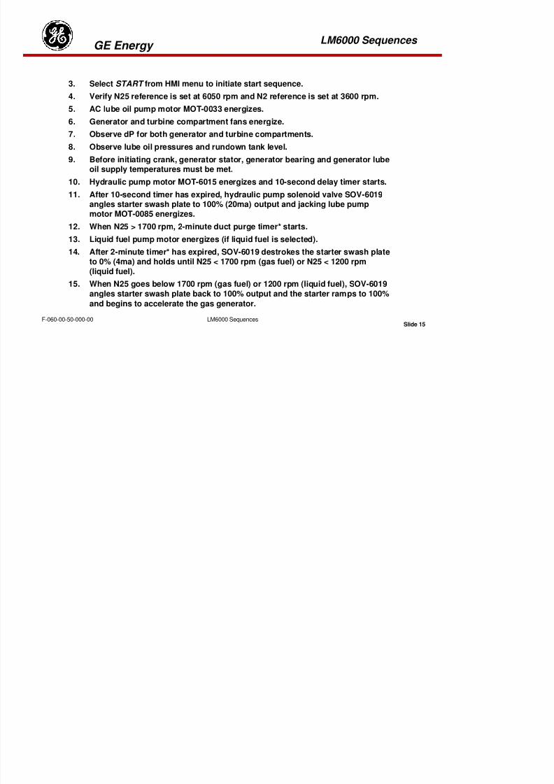
8/18/2019 71777896 - LM6000 Package Familiarization & Operations.pdf
http://slidepdf.com/reader/full/71777896-lm6000-package-familiarization-operationspdf 616/786
Slide 13LM6000 SequencesF-060-00-50-000-00
Typical Start Sequence
LM6000 Sequences GE Energy
NORMAL START SEQUENCE
Refer to the following sequence when performing a normal start:
1. Select NORMAL mode.
2. Permissives:
· All shutdowns cleared
· Not in 4-hour lockout
· Generator lube oil tank temp OK
· Generator lube oil tank level OK
· Hydraulic starter tank temp OK
· Hydraulic starter tank level OK
T bi l b il t k OK
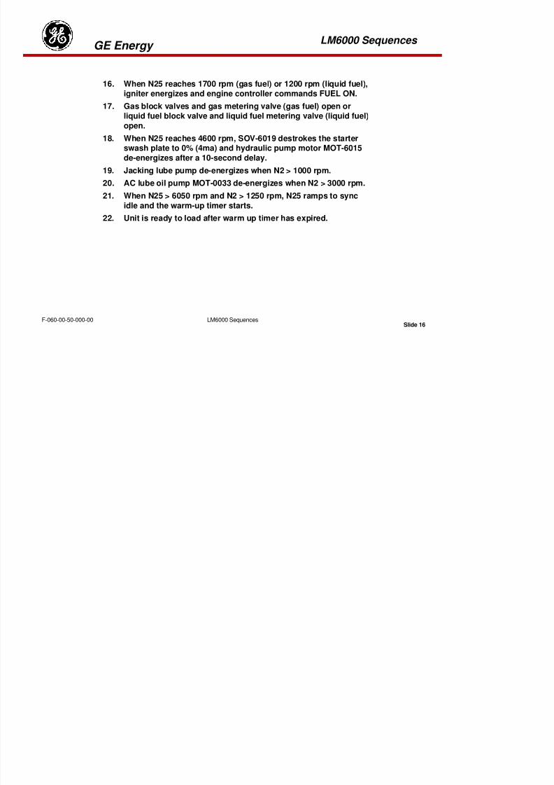
8/18/2019 71777896 - LM6000 Package Familiarization & Operations.pdf
http://slidepdf.com/reader/full/71777896-lm6000-package-familiarization-operationspdf 617/786
Slide 14LM6000 SequencesF-060-00-50-000-00
· Turbine lube oil tank OK
· Turbine lube oil tank level OK
· Normal run mode selected
· Engine control start permissive
· No forced signals exists in package or engine controller
· N25 less than 300 rpm
· Not in calibration mode
· Fuel system ready
LM6000 Sequences GE Energy
3. Select START from HMI menu to initiate start sequence.
4. Verify N25 reference is set at 6050 rpm and N2 reference is set at 3600 rpm.5. AC lube oil pump motor MOT-0033 energizes.
6. Generator and turbine compartment fans energize.
7. Observe dP for both generator and turbine compartments.
8. Observe lube oil pressures and rundown tank level.
9. Before initiating crank, generator stator, generator bearing and generator lubeoil supply temperatures must be met.
10. Hydraulic pump motor MOT-6015 energizes and 10-second delay timer starts.
11. After 10-second timer has expired, hydraulic pump solenoid valve SOV-6019

8/18/2019 71777896 - LM6000 Package Familiarization & Operations.pdf
http://slidepdf.com/reader/full/71777896-lm6000-package-familiarization-operationspdf 618/786
Slide 15LM6000 SequencesF-060-00-50-000-00
p y p pangles starter swash plate to 100% (20ma) output and jacking lube pumpmotor MOT-0085 energizes.
12. When N25 > 1700 rpm, 2-minute duct purge timer* starts.
13. Liquid fuel pump motor energizes (if liquid fuel is selected).
14. After 2-minute timer* has expired, SOV-6019 destrokes the starter swash plateto 0% (4ma) and holds until N25 < 1700 rpm (gas fuel) or N25 < 1200 rpm
(liquid fuel).
15. When N25 goes below 1700 rpm (gas fuel) or 1200 rpm (liquid fuel), SOV-6019angles starter swash plate back to 100% output and the starter ramps to 100%
and begins to accelerate the gas generator.
LM6000 Sequences GE Energy
16. When N25 reaches 1700 rpm (gas fuel) or 1200 rpm (liquid fuel),
igniter energizes and engine controller commands FUEL ON.17. Gas block valves and gas metering valve (gas fuel) open or
liquid fuel block valve and liquid fuel metering valve (liquid fuel)
open.
18. When N25 reaches 4600 rpm, SOV-6019 destrokes the starterswash plate to 0% (4ma) and hydraulic pump motor MOT-6015
de-energizes after a 10-second delay.19. Jacking lube pump de-energizes when N2 > 1000 rpm.
20. AC lube oil pump MOT-0033 de-energizes when N2 > 3000 rpm.
21. When N25 > 6050 rpm and N2 > 1250 rpm, N25 ramps to sync
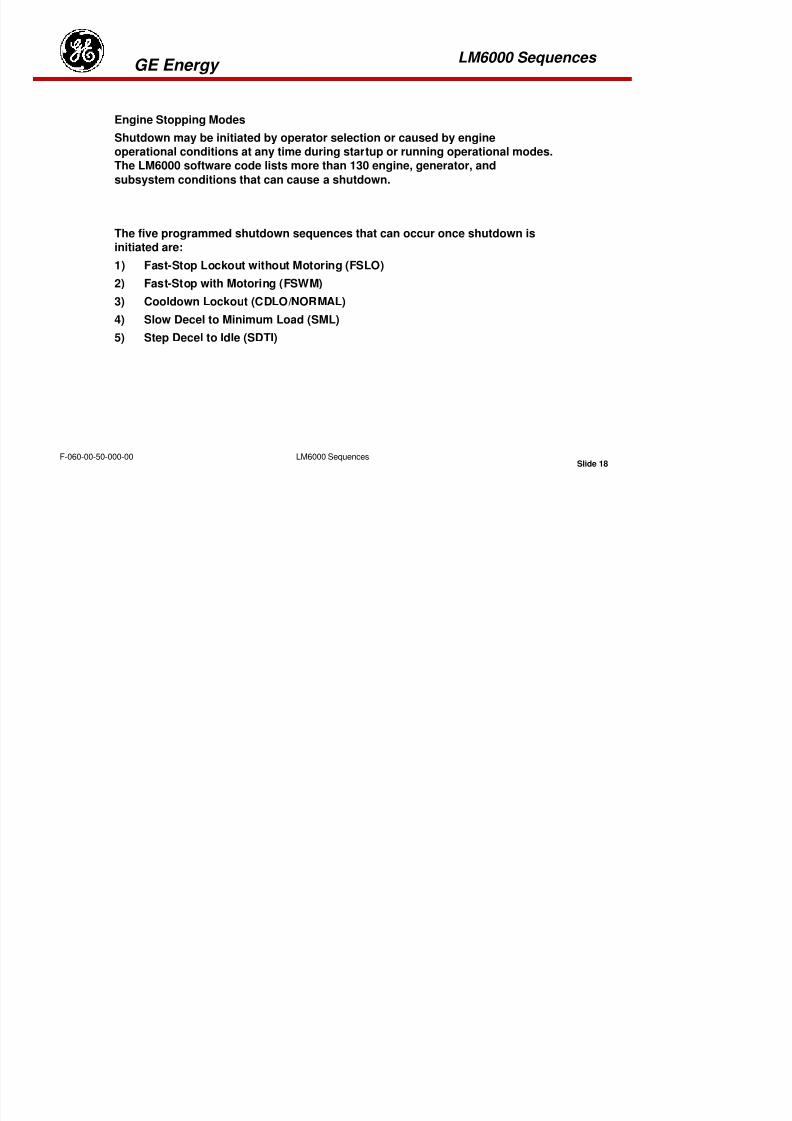
8/18/2019 71777896 - LM6000 Package Familiarization & Operations.pdf
http://slidepdf.com/reader/full/71777896-lm6000-package-familiarization-operationspdf 619/786
Slide 16LM6000 SequencesF-060-00-50-000-00
p p p y
idle and the warm-up timer starts.
22. Unit is ready to load after warm up timer has expired.
LM6000 Sequences GE Energy

8/18/2019 71777896 - LM6000 Package Familiarization & Operations.pdf
http://slidepdf.com/reader/full/71777896-lm6000-package-familiarization-operationspdf 620/786
Slide 17LM6000 SequencesF-060-00-50-000-00
Engine Stopping Modes
LM6000 Sequences GE Energy
Engine Stopping Modes
Shutdown may be initiated by operator selection or caused by engineoperational conditions at any time during startup or running operational modes.The LM6000 software code lists more than 130 engine, generator, and
subsystem conditions that can cause a shutdown.
The five programmed shutdown sequences that can occur once shutdown isinitiated are:
1) Fast-Stop Lockout without Motoring (FSLO)
2) Fast-Stop with Motoring (FSWM)
8/18/2019 71777896 - LM6000 Package Familiarization & Operations.pdf
http://slidepdf.com/reader/full/71777896-lm6000-package-familiarization-operationspdf 621/786
Slide 18LM6000 SequencesF-060-00-50-000-00
) p g ( )
3) Cooldown Lockout (CDLO/NORMAL)
4) Slow Decel to Minimum Load (SML)
5) Step Decel to Idle (SDTI)
LM6000 Sequences GE Energy
Fast-Stop Lockout without Motoring (FSLO)
An FSLO automatically initiates the following actions:• Fuel valves (and water or steam valves, if applicable) are closed
• The unit breaker is tripped open.
• Variable inlet guide vanes are closed.
• Variable bleed valves doors are opened (closed later during coast
down).• Ignition system and starter are deenergized.
• XN2, XN25, XNSD and oil pressure alarms are bypassed.
• Four hour lock-out if problem cannot be corrected in ten minutes.
8/18/2019 71777896 - LM6000 Package Familiarization & Operations.pdf
http://slidepdf.com/reader/full/71777896-lm6000-package-familiarization-operationspdf 622/786
Slide 19LM6000 SequencesF-060-00-50-000-00
When these steps are completed, drain and vent valves are opened,
alarms, interlocks, and start sequence timers are reset, and the operatingtime meter is turned off.
Fast-Stop with Motoring (FSWM)
An FSWM automatically initiates an FSLO, and then the starter is
engaged for 25 minutes when XN25 reaches 1700 RPM.
LM6000 Sequences GE Energy
Cooldown Lockout (CDLO/NORMAL)
A CDLO automatically initiates the following actions:
• Power is retarded to minimum load (synchronous idle).
• Shutdown steam/water and trip unit breaker.
• High-pressure rotor speed decreases to approximately 6400 rpm for 5 minutes.
• The starter is engaged for 20 minutes when XN25 drops to 1700 RPM.
• If reset clears shutdown during cool down period then CDLO is aborted.
NOTE: If on naphtha fuel, CDLO is replaced with FSWM.
8/18/2019 71777896 - LM6000 Package Familiarization & Operations.pdf
http://slidepdf.com/reader/full/71777896-lm6000-package-familiarization-operationspdf 623/786
Slide 20LM6000 SequencesF-060-00-50-000-00
LM6000 Sequences GE Energy
Slow Decel to Minimum Load (SML)
A slow decel to minimum load (min-load) is a controlled deceleration at a rate thatallows all engine schedules and engine cooling to be maintained at a controlledrate. Rather than decel all the way to core idle, the engine decels to the min-load
point. This allows the condition to be investigated without requiring a shutdown.
An SML automatically initiates the following actions:
• Fast load shed to minimum load in 20 seconds.
• If the problem still exists after 3 minutes then do a CDLO.
NOTE: If on naphtha fuel, SML is replaced with FSWM.
Step Decel to Idle (SDTI)

8/18/2019 71777896 - LM6000 Package Familiarization & Operations.pdf
http://slidepdf.com/reader/full/71777896-lm6000-package-familiarization-operationspdf 624/786
Slide 21LM6000 SequencesF-060-00-50-000-00
Step Decel to Idle (SDTI)
A step-decel to idle is an immediate rapid (max decel rate) deceleration to idle
followed by a 10-second pause, and then by a shutdown.
A step-decel provides a more controlled and orderly way of shutting down the
engine than does an immediate shutdown at power. The 10-second delay pause at
core idle allows various scheduled engine systems, such as variable inlet guidevanes (VIGV’s) and variable bleed valves (VBV’s), to reach a stabilized condition
before shutdown occurs.
LM6000 Sequences GE Energy
An SDTI automatically initiates the following actions:
•Power is immediately reduced to core idle, causing the engine to decel as rapidlyas possible.
•Ten (10) seconds after achieving core idle then FSLO.
NOTE: If on naphtha fuel, SDTI is replaced with FSWM.

8/18/2019 71777896 - LM6000 Package Familiarization & Operations.pdf
http://slidepdf.com/reader/full/71777896-lm6000-package-familiarization-operationspdf 625/786
Slide 22LM6000 SequencesF-060-00-50-000-00
Tab 18

8/18/2019 71777896 - LM6000 Package Familiarization & Operations.pdf
http://slidepdf.com/reader/full/71777896-lm6000-package-familiarization-operationspdf 626/786
8/18/2019 71777896 - LM6000 Package Familiarization & Operations.pdf
http://slidepdf.com/reader/full/71777896-lm6000-package-familiarization-operationspdf 627/786
ABBREVIATIONS AND ACRONYMS
THIS PAGE INTENTIONALLY LEFT BLANK
8/18/2019 71777896 - LM6000 Package Familiarization & Operations.pdf
http://slidepdf.com/reader/full/71777896-lm6000-package-familiarization-operationspdf 628/786
TECHNICAL MANUAL ABBREVIATIONS AND ACRONYMSA
A Ampere(s)
abs AbsoluteAC Alternating Current
acfm Actual Cubic Feet per Minuteacmm Actual Cubic Meter per Minute
AGB Accessory GearboxALF Aft, Looking Forward
Assy Assembly
ASTM American Society for Testing andMaterials
atm Atmosphere
AUX AuxiliaryAVRX Auxiliary Voltage Regulator
B
β (Beta) Variable Stator PositionBEM Brush Electrical Machines
8/18/2019 71777896 - LM6000 Package Familiarization & Operations.pdf
http://slidepdf.com/reader/full/71777896-lm6000-package-familiarization-operationspdf 629/786
bhp Brake Horsepower
BOP Balance of PlantBtu British Thermal Unit
C
C Degree Celsius (Centigrade)cc Cubic Centimeter
CCW Counterclockwise
CDLO Cooldown Lockout
CDP Compressor Discharge Pressurecfm Cubic Feet per Minute
CG Center of Gravitycid Cubic Inch Displacement
CIT Compressor Inlet Temperature
cm Centimeter
cm2 Square Centimeter
cm3 Cubic Centimeter
Cont ContinuedCRF Compressor Rear Frame
DC Direct CurrentDCS Digital Control System
DF Diesel Fuel
dn/dt Differential Speed/Differential Time(Rate of Change, Speed vs. Time)
dp Differential Pressuredp/dt Differential Pressure/Differential
Time-dPs3/dt Negative Rate of Change of High-
Pressure Compressor Static
PressureDSM Digital Synchronizing Module
Dwg. Drawing
E
EMU Engine Maintenance Unit
F
F Degree FahrenheitFCV Fl C t l V l

8/18/2019 71777896 - LM6000 Package Familiarization & Operations.pdf
http://slidepdf.com/reader/full/71777896-lm6000-package-familiarization-operationspdf 630/786
FCV Flow Control Valve
F&ID Flow & Instrument Diagram
Fig. Figure
FIR Full Indicator ReadingFMP Fuel Manifold Pressure
FOD Foreign-Object Damage
FLSO Fast Stop Lockout WithoutMotoring
FSWM Fast Stop With Motoring
ft Foot (Feet)ft2 Square Feet
ft3 Cubic Feet
ft-lb Foot-Pound
G
GA General Arrangement
gal Gallon(s)
GE General ElectricGG Gas Generator
hp HorsepowerHP High Pressure
HPC High-Pressure Compressor
HPCR High-Pressure Compressor RotorHPT High-Pressure Turbine
HPTR High-Pressure Turbine Rotorh Hour(s)
Hz Hertz (Cycles per Second)
I
ID Inside DiameterIEEE Institute of Electrical and
Electronics Engineers
IGHP Isentropic Gas HorsepowerIGKW Isentropic Gas Kilowatt
IGV Inlet Guide Vanein Inch(es)
in2 Square Inch
in3 Cubic Inch
in Hg Pressure Inches of Mercury
8/18/2019 71777896 - LM6000 Package Familiarization & Operations.pdf
http://slidepdf.com/reader/full/71777896-lm6000-package-familiarization-operationspdf 631/786
in-Hg Pressure, Inches of Mercury
in-lb Inch-Pound
in-Wg Pressure, Inches of Water
I/O Input/OutputIPB Illustrated Parts Breakdown
ISA Instrument Society of America
K
kg cm Kilogram-Centimeter
kg m Kilogram-Meterkohm Kilohm
kPa KiloPascal
kPad KiloPascal Differential
kPag KiloPascal GaugeK (CONT)
kV Kilovolt
kVA Kilovolt Ampere
kvar Kilovar
LEL Lower Explosive LimitLFL Lower Flammable Limit
LP Low Pressure
LPC Low-Pressure CompressorLpm Liters Per Minute
LPCR Low-Pressure Compressor RotorsLVDT Linear Variable-Differential
Transformer
M
m Meterm
2 Square Meter
m3 Cubic Meter
mA MilliampereMaint. Maintenance
MAVR Modular Automatic VoltageRegulator
mb Millibar
MCC Motor Control CenterMGTBMain Generator Terminal Box
8/18/2019 71777896 - LM6000 Package Familiarization & Operations.pdf
http://slidepdf.com/reader/full/71777896-lm6000-package-familiarization-operationspdf 632/786
MGTB Main Generator Terminal Box
MHz Megahertz
MIL Military
MIL-SPEC Military SpecificationMIL-STD Military Standard
min Minute(s)
mm MillimeterMohm Megohm(s)
mph Miles Per Hour
MTTB Main Turbine Terminal BoxMvar Megavar
MW Megawatt
N NEMA National Electrical Manufacturers
Association
Nm Newton Meter
NOx Oxides of Nitrogen
Total PressureP25 High-Pressure Compressor Inlet
Total Pressure
P48 Low-Pressure Turbine Inlet TotalPressure
Pamb Ambient PressurePara. Paragraph
P (CONT)PCB Printed Circuit Board
PF Power Factor
PMG Permanent Magnet Generator ppm Parts Per Million
Ps3 High-Pressure Compressor
Discharge Static PressurePs25 High-Pressure Compressor Inlet
Static PressurePs55 Low-Pressure Turbine Discharge
Static Pressure
psia Pounds per Square Inch Absolutepsid Pounds per Square Inch

8/18/2019 71777896 - LM6000 Package Familiarization & Operations.pdf
http://slidepdf.com/reader/full/71777896-lm6000-package-familiarization-operationspdf 633/786
psid Pounds per Square Inch
Differential
psig Pounds per Square Inch Gauge
PT Pressure TransmitterPTO Power Takeoff
Rrms Root Mean Square
rpm Revolutions Per Minute
RTD Resistance Temperature DetectorRTV Room Temperature Vulcanizing
S
scfm Standard Cubic Feet per Minutescmm Standard Cubic Meters per Minute
SDTI Step Decelerate to Idle
sec Second(s)
SG Specific Gravityshp Shaft Horsepower
TT2 Low-Pressure Compressor Inlet
Total Temperature
T3 High-Pressure CompressorDischarge Temperature
T25 High-Pressure Compressor InletTemperature
T48 Low-Pressure Turbine InletTemperature
Tamb Ambient Temperature
TAN Total Acid NumberTBD To Be Determined
TGB Transfer Gearbox
theta 2 Ratio of Measure Absolute GasGenerator Inlet Temperature to
Standard Day AbsoluteTemperature
TIT Turbine Inlet Temperature
TRF Turbine Rear Frame

8/18/2019 71777896 - LM6000 Package Familiarization & Operations.pdf
http://slidepdf.com/reader/full/71777896-lm6000-package-familiarization-operationspdf 634/786
V
V VoltVAC Volts, Alternating Currentvar Volt-Ampere Reactive
VBV Variable Bypass Valve
VDC Volts, Direct CurrentVG Variable Geometry
V (CONT)
VIGV Variable Inlet Guide VaneVSV Variable Stator Vane
W
W WattW2 Low Pressure Compressor Physical
Airflow
W25 High Pressure Compressor Physical
AirflowWf Flow Fuel
XN2R Low-Pressure Rotor Speed -
Corrected
XN25 High-Pressure Compressor Speed -Physical
XN36 Acoustic monitor DLE
XN25R High-Pressure Compressor Speed -Corrected
XNSD Low-Pressure Turbine Speed

8/18/2019 71777896 - LM6000 Package Familiarization & Operations.pdf
http://slidepdf.com/reader/full/71777896-lm6000-package-familiarization-operationspdf 635/786
THIS PAGE INTENTIONALLY LEFT BLANK

8/18/2019 71777896 - LM6000 Package Familiarization & Operations.pdf
http://slidepdf.com/reader/full/71777896-lm6000-package-familiarization-operationspdf 636/786
GLOSSARY

8/18/2019 71777896 - LM6000 Package Familiarization & Operations.pdf
http://slidepdf.com/reader/full/71777896-lm6000-package-familiarization-operationspdf 637/786
GLOSSARY
This Page Intentionally Left Blank

8/18/2019 71777896 - LM6000 Package Familiarization & Operations.pdf
http://slidepdf.com/reader/full/71777896-lm6000-package-familiarization-operationspdf 638/786
GLOSSARY
A
A/D Conversion – Analog-to-Digital Conversion: A con-version that takes an analog input
in the form of electrical voltage or current and produces a digital output.
ABT – Automatic Bus Transfer: For critical loads, normal and alternate, power sources are provided. The power sources are supplied from separate switchboards through separate cable
runs. Upon loss of the normal power supply, the transfer switch automatically disconnects
this source and shifts the load to the alternate source.
AC – Alternating Current: Alternating current is an electric current that flows first in one
direction for a given period of time, and then in the reverse direction for an equal period of
time, constantly changing in magnitude.
A – Ampere: A unit of electrical current or rate of flow of electrons. One volt across oneohm of resistance causes a current flow of one ampere.
Analog Signal: An analog signal is a measurable quantity that is variable throughout a givenrange and is representative of a physical quantity.

8/18/2019 71777896 - LM6000 Package Familiarization & Operations.pdf
http://slidepdf.com/reader/full/71777896-lm6000-package-familiarization-operationspdf 639/786
Annular: In the form of, or forming, a ring.
Anti-Icing: A system for preventing the buildup of ice on the gas turbine intake systems.
APD – Automatic Paralleling Device: Automatically parallels any two gas turbine-
generator sets.
B
Babbitt: A white alloy of tin, lead, copper, and antimony which is used for lining bearings.
BAS – Bleed-Air System: The BAS uses as its source compressed air extracted from the
compressor stage of each gas turbine module and gas turbine-generator set. The BAS is usedfor anti-icing, prairie air, masker air, and low-pressure gas turbine starting for both the gas
turbine module and the gas turbine-generator set.
Borescope: A small periscope used to visually inspect internal engine components.
BTB – Buss Tie Breaker: A BTB is used to connect one main switchboard to another main
switchboard.Buffer: To electronically isolate and filter an electrical signal from its source.
Bus: The term used to specify an uninsulated power conductor.
C
CB – Circuit Breaker: An automatic protective device that, under abnormal conditions,
will open a current-carrying circuit.
CIT – Compressor Inlet Temperature (T2): CIT is the temperature of the air entering the
gas turbine compressor as measured at the front frame. CIT is one of the parameters used forcalculating engine power output (torque) and scheduling fuel flow and variable stator vane
angle.
Coalesce: To grow together, unite, or fuse, as uniting small liquid particles into large
droplets. This principle is used to remove water from fuel in the filter/separator.
Condensate: The product of reducing steam (gas) to a liquid; (water) For example as used
8/18/2019 71777896 - LM6000 Package Familiarization & Operations.pdf
http://slidepdf.com/reader/full/71777896-lm6000-package-familiarization-operationspdf 640/786
Condensate: The product of reducing steam (gas) to a liquid; (water). For example, as used
in the distilling process.
D
D/A Conversion – Digital-to-Analog Conversion: A con-version that produces an analogoutput in the form of voltage or current from a digital input.
DC – Direct Current: Direct current is an electric current that flows in one direction. A pure direct current is one that will continuously flow at a constant rate.
Deaerator: A deaerator is a device that removes air from oil as in the LS&C tank (gas
turbine module) which separates air from scavenged oil.
Delta P – Differential Pressure: The pressure drop across a fixed device.
Demisters: A moisture-removal device that separates water from air.
Dessicant: A substance having a great affinity for water and used as a drying agent
E
Eductor: The eductor is a mixing tube which is used in the gas turbine module exhaust
system. It is physically positioned at the top of the stack so that the gas flow from the gasturbine module exhaust nozzles will draw outside air into the exhaust stream as it enters the
mixing tube.
EG – Electronic Governor: An electronic governor is a system that uses an electroniccontrol unit, in conjunction with an electrohydraulic governor actuator, to control the position
of the liquid fuel valve on the gas turbine-generator set and regulate engine speed.
F
Fault Alarm: This type of alarm is used in the Fuel Oil Control System and Damage ControlConsole. It indicates that a sensor circuit has opened.
FO System – Fuel Oil System: The FO system provides a continuous supply of clean fuel tothe gas turbine module and to the gas turbine-generator set. The gas turbine module and gasturbine-generator set can operate on DFM, ND, and JP-5.
FOD – Foreign-Object Damage: Damage as a result of entry of foreign objects into a gas

8/18/2019 71777896 - LM6000 Package Familiarization & Operations.pdf
http://slidepdf.com/reader/full/71777896-lm6000-package-familiarization-operationspdf 641/786
FOD Foreign Object Damage: Damage as a result of entry of foreign objects into a gas
turbine engine.
G
GB – Generator Breaker: Circuit breaker used to connect a gas turbine-generator set to itsmain switchboard.
GCU – Generator Control Unit: A static GCU is supplied for each gas turbine-generator
set consisting of a static exciter/voltage regulator assembly, field rectifier assembly, motor-driven rheostat, and a mode select rotary switch. It controls the output voltage of thegenerator.
Governor Droop Mode: Droop mode is normally used only for paralleling with shore power. Because shore power is an infinite bus, droop mode is necessary to control the loadcarried by the gas turbine-generator set. If a gas turbine-generator set is paralleled with shore power, and one attempts to operate in isochronous mode instead of droop mode, the gas
turbine-generator set governor speed reference can never be satisfied because the gas turbine-
Governor Isochronous Mode: The isochronous mode is normally used for gas turbine-generator set operation. This mode provides a constant frequency for all load conditions.When operating two gas turbine-generator sets in parallel isochronous mode, it also providesequal load sharing between the units.
GTG Set – Gas Turbine-Generator Set: The GTG set consists of a gas turbine engine; areduction gearbox; and a three-phase, alternating-current generator rated at 2000 kW and 450VAC.
GTM – Gas Turbine Module: The GTM consists of the main propulsion gas turbine unit,including the gas turbine engine, base, enclosure, shock-mounting system, fire detection andextinguishing system, and the enclosure environmental control components.
H
Header: This is a piping manifold that connects several sub-lines to a major pipeline.
Head Tank: A tank located higher than other system components to provide a positive
pressure to a system by gravity.
Helix: A tube or solid material wrapped like threads on a screw.
8/18/2019 71777896 - LM6000 Package Familiarization & Operations.pdf
http://slidepdf.com/reader/full/71777896-lm6000-package-familiarization-operationspdf 642/786
pp
High-Hat Assembly: A removable housing over the main engine air intake ducts, which
contains the moisture-separating system, inlet louvers, and blow-in doors.
Hz – Hertz: A unit of frequency equal to one cycle per second.
I
I/O – Input/Output: The interfacing of incoming and outgoing signals from the computer tothe controlled device.
IGV – Inlet Guide Vanes: Vanes ahead of the first stage of compressor blades of a gas
turbine engine whose function is to guide the inlet air into the gas turbine compressor at the
optimum angle.
Immiscible: Incapable of being mixed.
ISO – Isochronous: Governing with steady-state speed regulation of essentially zeromagnitude.
L
Labyrinth/Windback Seals: The labyrinth/windback seals combine a rotating element witha smooth-surface stationary element to form an oil seal. This type of seal is used in
conjunction with an air seal, with a pressurization air cavity between the two seals. Pressurein the pressurization air cavity is always greater than the sump pressure, therefore, flow across
the seal is toward the sump, thus preventing oil leakage from the sump. The windback is a
course thread on the rotating element of the oil seal which, by screw action, forces any oilwhich might leak across the seal back into the sump.
Latent: Present, but not visible or apparent.
LED – Light-emitting Diode: A solid-state device which, when conducting, emits light.The LEDs are used for the digital displays and card fault indicators in the local control panel
and other electronic systems.
Liquid Fuel Valve: Meters the required amount of fuel for all engine operating conditions
for the GTG set engine.
8/18/2019 71777896 - LM6000 Package Familiarization & Operations.pdf
http://slidepdf.com/reader/full/71777896-lm6000-package-familiarization-operationspdf 643/786
for the GTG set engine.
Load Shedding: Generator overpower protection by automatically dropping preselectednonvital loads when generator output reaches 100% for 3 seconds, and additional dropping of
preselected semivital loads if the overload condition exists for another 5 seconds.
Local Control: Startup and operation of equipment by means of manual controls attached to
the machinery, or by the electric panel attached to the machinery or located nearby.
LOCOP – Local Control Panel: Electronic enclosure containing operating and monitoring
equipment used to control the turbine during operation. The control elements of the system
are powered by 28 VDC from the switchboard or batteries.
M
micron: A unit of measure equal to one-millionth of a meter.
mil: A unit of measure equal to one thousandth of an inch
O
Orifice: A restricted opening used primarily in fluid systems.
PPCB – Printed Circuit Board: An electronic assembly mounted on a card using etched
conductors. Also called Printed Wiring Board (PWB).
PF – Power Factor: The ratio of the average (or active) power to the apparent power (root-
mean-square voltage × rms current) of an alternating-current circuit.
Pinion: A smaller gear designed to mesh with a larger gear.
Pitch: A term applied to the distance a propeller will advance during one revolution.
PMA – Permanent Magnet Alternator: PMA is mounted on the generator shaft extension
of each GTG set and supplies speed sensing and power to the EG. PMA also supplies initialgenerator excitation.
Poppet-Type Check Valve: A valve that moves into and from its seat to prevent oil from

8/18/2019 71777896 - LM6000 Package Familiarization & Operations.pdf
http://slidepdf.com/reader/full/71777896-lm6000-package-familiarization-operationspdf 644/786
pp yp p
draining into the GTG set when the engine is shut down.
ppm – Parts Per Million: Unit of measure.
pps – Pulses Per Second: Unit of measure.
psi – Pounds per Square Inch: Unit of measure (pressure).
psia – Pounds per Square Inch Absolute: Unit of measure (pressure).
psid – Pounds per Square Inch Differential: Unit of measure (pressure).
psig – Pounds per Square Inch Gage: Unit of measure (pressure).
PTO – Power Takeoff: PTO is the drive shaft between the GTG set, gas turbine engine, and
the reduction gearbox. Transfers power from the gas turbine to the reduction gearbox to drivethe generator
Rabbet Fit: A groove, depression, or offset in a member into which the end or edge ofanother member is fitted, generally so that the two surfaces are flush. Also known as register
and spigots.
Radio-Frequency Interference: An electrical signal capable of being propagated into, and
interfering with, the proper operation of electrical or electronic equipment.RTD – Resistance Temperature Detector: Same as RTE.
RTE – Resistance Temperature Element: These temperature sensors work on the principle
that as temperature increases, the conductive materials exposed increase their electrical
resistance.
S
Scavenge Pump: Used to remove oil from a sump and return it to the oil supply tank.
scfm – Standard Cubic Feet per Minute: Unit of measure.
Sensor: A device that responds to a physical stimulus and transmits a result impulse forremote monitoring.
8/18/2019 71777896 - LM6000 Package Familiarization & Operations.pdf
http://slidepdf.com/reader/full/71777896-lm6000-package-familiarization-operationspdf 645/786
Serial Data Bus: The bus is time-shared between the LOCOP and the end device. Controland status information are exchanged in the form of serial data words.
Stall: An inherent characteristic of all gas turbine compressors to varying degrees and under
certain operating conditions. It occurs whenever the relationship between air pressure,velocity, and compressor rotational speed is altered to such extent that the effective angle of
attack of the compressor blades becomes excessive, causing the blades to stall in much the
same manner as an aircraft wing.
Sync – Synchronize: The state where connected alternating-current systems operate at the
same frequency and where the phase-angle displacements between voltages in them are
constant or vary about a steady and stable average value.
SWBD – SWitchBoarD: A large panel assembly which mounts the control switches, circuit
breakers, instruments, and fuses essential to the operation and protection of electricaldistribution systems.
U
Ultraviolet Flame Detectors: Ultraviolet flame detectors sense the presence of fire in theGTM and GTG set and generate an electrical signal to the alarm panel.
X
XDCR – Transducer: The XDCR is a sensor that converts quantities such as pressure,
temperature, and flow rate into electrical signals.
XFR – Transfer: The theoretical relationship between measure and output values, as
determined by inherent principles of operation.

8/18/2019 71777896 - LM6000 Package Familiarization & Operations.pdf
http://slidepdf.com/reader/full/71777896-lm6000-package-familiarization-operationspdf 646/786
8/18/2019 71777896 - LM6000 Package Familiarization & Operations.pdf
http://slidepdf.com/reader/full/71777896-lm6000-package-familiarization-operationspdf 647/786
GAS TURBINE ENGINE THEORY
DEFINITIONS
THIS PAGE INTENTIONALLY LEFT BLANK
8/18/2019 71777896 - LM6000 Package Familiarization & Operations.pdf
http://slidepdf.com/reader/full/71777896-lm6000-package-familiarization-operationspdf 648/786
GAS TURBINE ENGINE THEORY DEFINITIONS
INTRODUCTION
This information sheet has been prepared to aid the student in his understanding of the basic principles of physics, the gas laws, thermodynamics, and the Brayton cycle, which are
associated with gas turbine engine operation. A thorough knowledge of these principles will
greatly aid the student throughout his career in the Gas Turbine field.
REFERENCES
Aircraft Gas Turbine Engine Technology
Sawyer’s Turbomachinery Maintenance Handbook
Modern Marine Engineers Manual
Handbook of Physics and Chemistry
Basic Thermodynamics
DEFINITIONS

8/18/2019 71777896 - LM6000 Package Familiarization & Operations.pdf
http://slidepdf.com/reader/full/71777896-lm6000-package-familiarization-operationspdf 649/786
Absolute pressure P The actual pressure applied to a system. Normally found byadding a value of 14.7 to gauge readings. (Normal units are expressed as pounds per square
inch, absolute (psia).)
Absolute temperature T Temperature that is reckoned form the absolute zero.(Normal units are expressed as either degrees Rankine or degrees Kelvin.)
Absolute zero The point at which all molecular activity ceases. Computed to be a
temperature of approximately –460 degrees Fahrenheit (−460° F) or –273 degrees Celsius
(−273° C).
Acceleration a The rate of change of velocity, in either speed or direction. (Normalunits are expressed as feet per second squared (ft/sec
2).)
Adiabatic As applied to thermodynamics applies to a process or cycle that occursith t l i f h t
Bernoulli theorem As a fluid flows through a restricted area such as a nozzle, the
velocity of the fluid will increase with a corresponding decrease in pressure and a slight
decrease in temperature. The inverse is true for fluid flow through a diffuser.
Boyle’s law If the absolute temperature of a given quantity of gas is held constant,the absolute pressure of the gas is inversely proportional to the volume the gas is allowed to
occupy.
Brayton cycle The thermodynamic cycle on which all gas turbine engines operate,
considered to be a constant pressure cycle (combustion occurs at a constant pressure).
British thermal unit Btu Defined as the quantity of heat required to raise the temperature
of a 1-pound mass of water 1 degree Fahrenheit (1° F). (Water is to be pure distilled water,and the temperature change is from 64 degrees Fahrenheit (64° F) to 65 degrees Fahrenheit
(65° F).)
Cascade effect As related to compressor stall, cascade effect is where
turbulence created in the forward stages of the compression section is passed rearwardthrough the compressor, with an increase in the total amount of turbulence with each
successive stage.
8/18/2019 71777896 - LM6000 Package Familiarization & Operations.pdf
http://slidepdf.com/reader/full/71777896-lm6000-package-familiarization-operationspdf 650/786
Celsius (centigrade) °C Normally used by scientists, a temperature scale in which the
temperature θc in degrees Celsius (°C) is related to the temperature Tk in kelvins by theformula:
θc = Tk − 273.15.
Charles’ law If the absolute pressure of a given quantity of gas is held constant, thevolume the gas is allowed to occupy is directly proportional to the absolute temperature of the
gas.
Compound blading A blending of both reaction and impulse turbine blading such
that the actual blades are impulse at the root and reaction at the tip. It is the most common
type of blading used in the turbine and power turbine sections of modern gas turbine engines.
Compressor discharge pressure CDP The actual pressure of the air exiting the
Compressor inlet pressure CIP The pressure of the air at the inlet to the inlet guide vanes of
the compressor. Normally slightly less than atmospheric pressure.
Compressor inlet temperature CIT The temperature of the air which actually enters
the compressor. Normally measured at the inlet bellmouth.
Compressor stall When turbulence across the stages of the compressor becomes severe
enough (owing to the cascade effect), the actual airflow through the compressor is disrupted
and decreases. During compressor stall, it is not common to see a reduction in the rpm of the
compressor section, only a reduction in the actual air- flow through the compressor.
Compressor ratio C/R A ratio of the compressor discharge pressure divided by the
compressor inlet pressure.
Compressor ratio per stage CR/STG The pressure rise that each individual stage in the
compressor can handle. It has been determined that in an axial-flow compressor, themaximum CR/STG is approximately 1.2-to-1.
Conduction A method of heat transfer in which one area of a substance is heated,
causing an increase in the molecular vibrations at that point. These increased vibrations are
t itt d f t t t th h t th l th f th b t

8/18/2019 71777896 - LM6000 Package Familiarization & Operations.pdf
http://slidepdf.com/reader/full/71777896-lm6000-package-familiarization-operationspdf 651/786
transmitted from atom to atom throughout the length of the substance.
Configuration How something is put together.
Conservation of momentum During an elastic collision with no losses owing to heat
or friction, the total momentum of Object 1 must equal the total momentum of Object 2.
Convection A method of heat transfer in which one area of a fluid is heated,
causing a current to be set up that transfers the heat throughout the fluid.
Cycle A process that begins with certain conditions and ends at the originalconditions.
Cycle efficiency The output horsepower of the engine divided by the input
energy used. In the case of all gas turbine engines, efficiency is equal to work rate brakedivided by heat rate of addition (the units for both must be the same). (Normal units are
expressed as percent (%) )
Dovetail A type of blade attachment normally used to attach the rotating blades
in the compressor section of an axial-flow compressor to the disk.
Elastic collision In physics, a collision in which there are no losses owing to
friction or heat, and no plastic deformation occurs.
Energy E The capacity to do work. (Normal units are expressed as foot pounds
(ft-lb.).)
Exhaust gas temperature EGT The temperature of the gases that are exhausted
from the engine. (Normal units are expressed as degrees Fahrenheit (°F).)
Exit guide vanes EGV Used in most axial-flow compressors to reduce the total amount
of turbulence that is passed from the compressor section to the combustion section of theengine.
Fahrenheit °F Degrees Fahrenheit. A temperature scale normally used by engineers(not an absolute temperature scale).
First law of thermodynamics Energy is indestructible and interconvertible

8/18/2019 71777896 - LM6000 Package Familiarization & Operations.pdf
http://slidepdf.com/reader/full/71777896-lm6000-package-familiarization-operationspdf 652/786
First law of thermodynamics Energy is indestructible and interconvertible.Three main points: (1) Energy cannot be created or destroyed; (2) energy can change forms;and (3) energy is conserved for any system, open or closed.
Fir tree A type of blade attachment normally used to hold the rotating blades of anaxial-flow turbine to the turbine disk or wheel.
Fluid Any substance which conforms to the shape of its container (may be either
liquid or gas).
Force F A vector quantity that tends to produce, modify, or retard motion. (Normal
units are expressed as pounds (lb).)
Fuel flow Wf The amount of fuel an engine is using at any given time. (Normal unitsare expressed as gallons per hour (gal/hr).)
Function How something is accomplished
Gas turbine engine GTE A form of internal combustion heat engine that operates on theBrayton cycle, and in which all events occur continuously during normal engine operation.
Gauge pressure psig The actual pressure readings taken from gauges that arecalibrated to read absolute pressure.
General gas law A combination of both Boyle’s law and Charles’ law.
Gravity g The gravitational attraction of the mass of the earth, the moon, or a
planet for bodies at or near its surface. On earth, the acceleration owing to gravity is 32.174
ft/sec2.
Heat Q The energy associated with the random motion of atoms, molecules, and
smaller structural units of which matter is composed..
Heat rate of addition Qa The amount of energy (in Btu/min) which is added during the
combustion process in the gas turbine engine.
DEFINITIONS (CONT)
.
Heat rate of rejection Qr A loss for a gas turbine engine. The amount of energy
that was added during the gas turbine engine cycle, but was not extracted in the turbine
section and was exhausted to the atmosphere (Normal units are expressed in British thermal

8/18/2019 71777896 - LM6000 Package Familiarization & Operations.pdf
http://slidepdf.com/reader/full/71777896-lm6000-package-familiarization-operationspdf 653/786
section and was exhausted to the atmosphere. (Normal units are expressed in British thermalunits per minute (Btu/min).)
Heat transfer The transfer of thermal energy between two or more bodies orsubstances.
Height hgt The extent of elevation above a level. (Normal units are expressed as feet (ft).)
Horsepower hp The unit of power in the British engineering system, equal to 550 foot- pounds per second, approximately 745.7 watts.
Impulse blading A type of turbine or power turbine blading which operates
principally by the conservation of momentum.
Inlet guide vanes IGV A set of vanes located in the forward part of the axial-flow
compressor which are used to direct the incoming air at a predetermined angle toward the
direction of rotation of the first stage blades
8/18/2019 71777896 - LM6000 Package Familiarization & Operations.pdf
http://slidepdf.com/reader/full/71777896-lm6000-package-familiarization-operationspdf 654/786
8/18/2019 71777896 - LM6000 Package Familiarization & Operations.pdf
http://slidepdf.com/reader/full/71777896-lm6000-package-familiarization-operationspdf 655/786
Time t A measured or measurable period during which an action, process, or conditionexists or continues.
Tip clang The actual bending of the rotating blades used in an axial-flowcompressor when the pressures across the blades become excessive because of the turbulence
of stall. When these have enough pressure to cause them to physically bend, they can actually
contact the stationary vanes; when this occurs, the condition is known as tip clang.
Turbine inlet temperature TIT The temperature of the gases exiting the combustion
section of the engine and entering the turbine section.
Total energy E t The algebraic sum of the potential and kinetic energy of a body or substance.
Velocity vel Speed in a given direction; a vector quantity. (Normal units areexpressed as feet per second (ft/sec) or revolutions per minute (rpm).)
Vector quantity A quantity that has both magnitude and direction.
Volume V Cubic capacity. (Normal units are expressed as cubic feet (ft3) or cubic
inches (in3).)
Weight wt A measure of the pull of gravity on a quantity of matter. (Normal units are expressedas pound(s) (lb) )
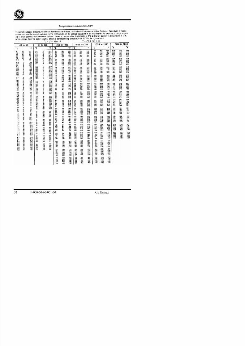
8/18/2019 71777896 - LM6000 Package Familiarization & Operations.pdf
http://slidepdf.com/reader/full/71777896-lm6000-package-familiarization-operationspdf 656/786
g p g y q y ( pas pound(s) (lb).)
Work W Work is equal to the product of the force applied to an object, multiplied by the
distance through which the force acts.
Work rate brake Wb The actual output horsepower that is produced by an engine.
Work rate of compression Wc The calculated value of power required to drive the
compressor sections of a GTE.
Work rate turbine Wt The amount of work extracted from the hot gases in the turbine
section. This work must be utilized to drive both the compressor section and the engine’s load in the
single-shaft engine, and the value of work rate turbine is used only to drive the compressor in the split-
shaft engines. (Normal units are expressed as horsepower (hp).)
CONVERSION CHARTS
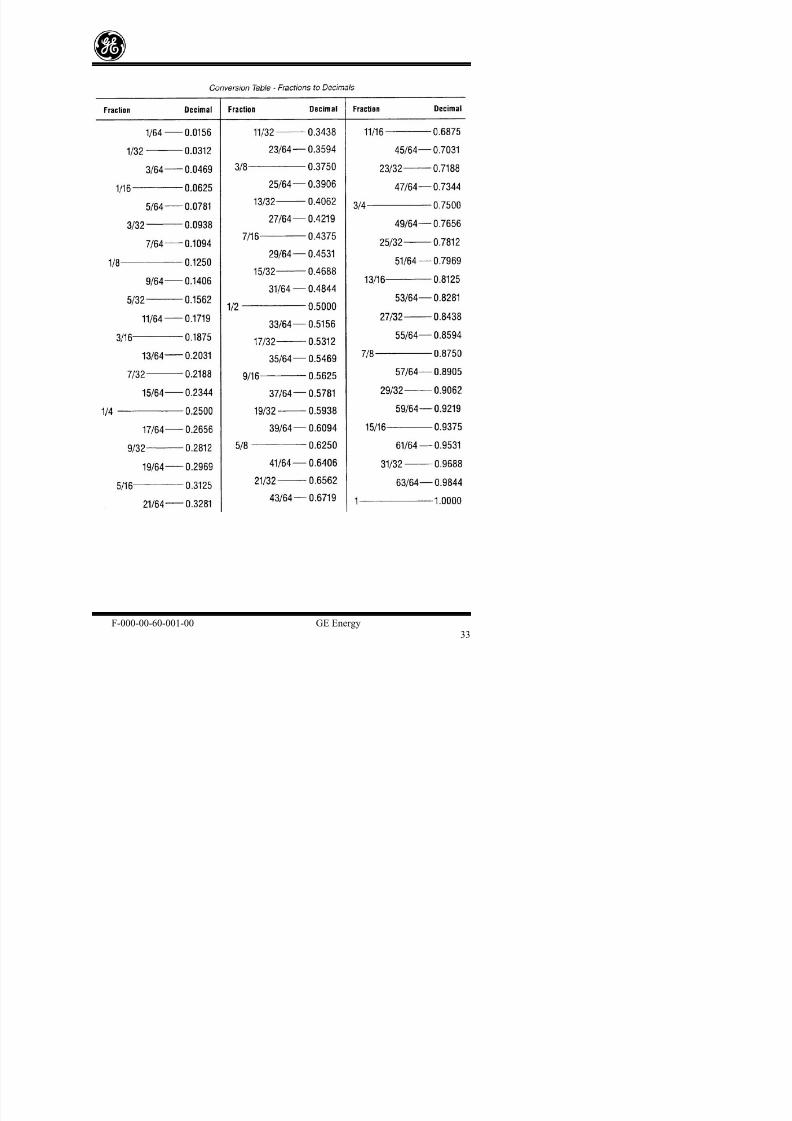
8/18/2019 71777896 - LM6000 Package Familiarization & Operations.pdf
http://slidepdf.com/reader/full/71777896-lm6000-package-familiarization-operationspdf 657/786
CONVERSION CHARTS

8/18/2019 71777896 - LM6000 Package Familiarization & Operations.pdf
http://slidepdf.com/reader/full/71777896-lm6000-package-familiarization-operationspdf 658/786

8/18/2019 71777896 - LM6000 Package Familiarization & Operations.pdf
http://slidepdf.com/reader/full/71777896-lm6000-package-familiarization-operationspdf 659/786

8/18/2019 71777896 - LM6000 Package Familiarization & Operations.pdf
http://slidepdf.com/reader/full/71777896-lm6000-package-familiarization-operationspdf 660/786
GE Energy Technical Training
LM6000 GAS TURBINE GENERATOR NAVIGAT BORANG
BASIC PACKAGE FAMILIARIZATION/OPERATIONS 2012
TRAINING COURSE
Reference Drawings
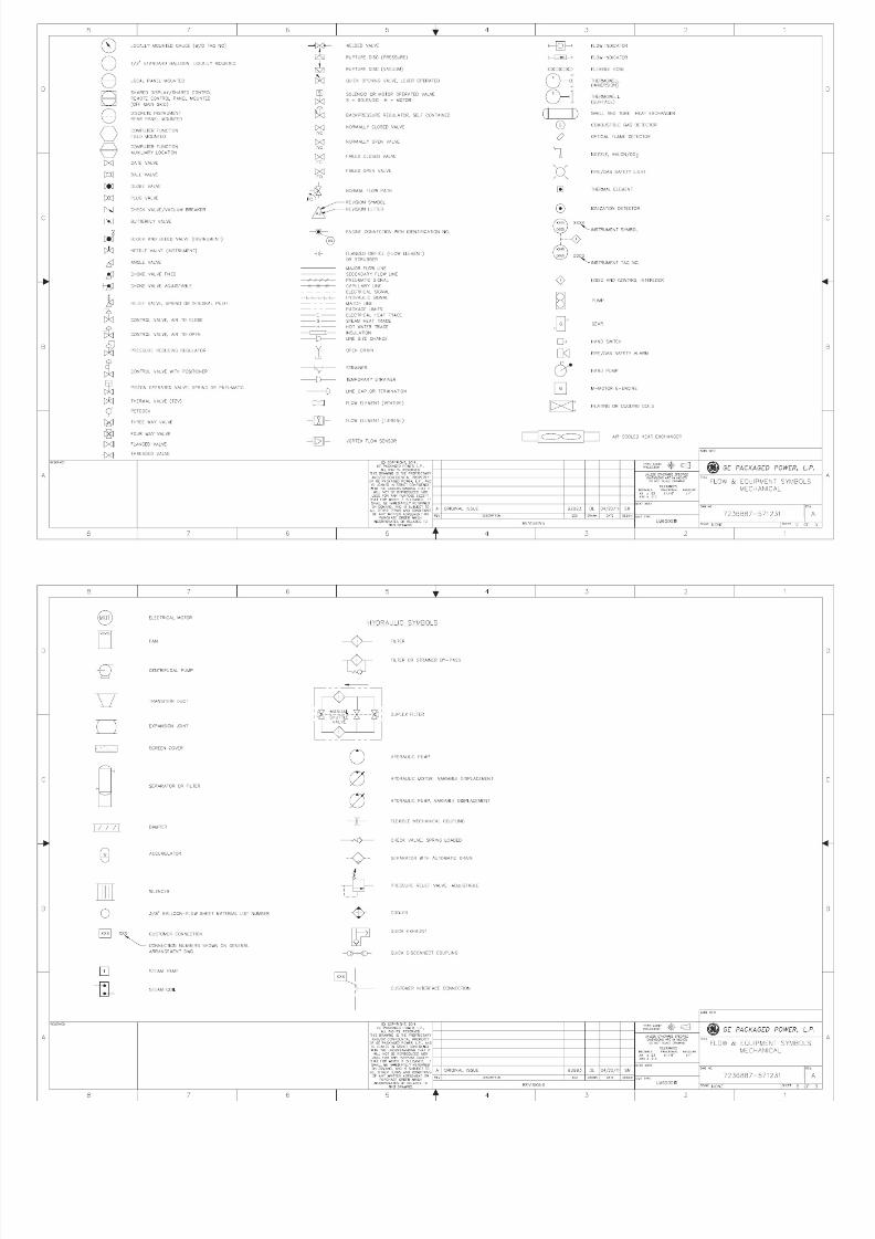
8/18/2019 71777896 - LM6000 Package Familiarization & Operations.pdf
http://slidepdf.com/reader/full/71777896-lm6000-package-familiarization-operationspdf 661/786
Tab A

8/18/2019 71777896 - LM6000 Package Familiarization & Operations.pdf
http://slidepdf.com/reader/full/71777896-lm6000-package-familiarization-operationspdf 662/786
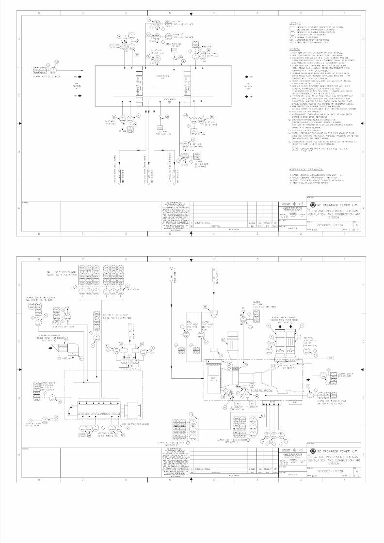
8/18/2019 71777896 - LM6000 Package Familiarization & Operations.pdf
http://slidepdf.com/reader/full/71777896-lm6000-package-familiarization-operationspdf 663/786
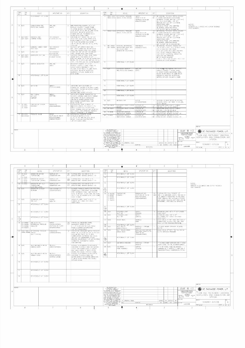
8/18/2019 71777896 - LM6000 Package Familiarization & Operations.pdf
http://slidepdf.com/reader/full/71777896-lm6000-package-familiarization-operationspdf 664/786
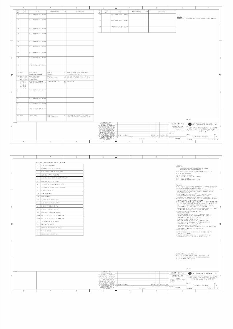
8/18/2019 71777896 - LM6000 Package Familiarization & Operations.pdf
http://slidepdf.com/reader/full/71777896-lm6000-package-familiarization-operationspdf 665/786
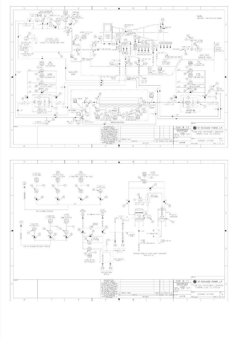
8/18/2019 71777896 - LM6000 Package Familiarization & Operations.pdf
http://slidepdf.com/reader/full/71777896-lm6000-package-familiarization-operationspdf 666/786
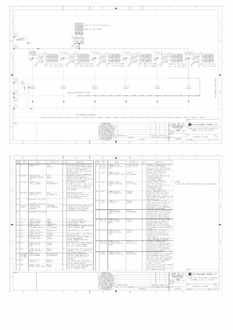
8/18/2019 71777896 - LM6000 Package Familiarization & Operations.pdf
http://slidepdf.com/reader/full/71777896-lm6000-package-familiarization-operationspdf 667/786

8/18/2019 71777896 - LM6000 Package Familiarization & Operations.pdf
http://slidepdf.com/reader/full/71777896-lm6000-package-familiarization-operationspdf 668/786

8/18/2019 71777896 - LM6000 Package Familiarization & Operations.pdf
http://slidepdf.com/reader/full/71777896-lm6000-package-familiarization-operationspdf 669/786
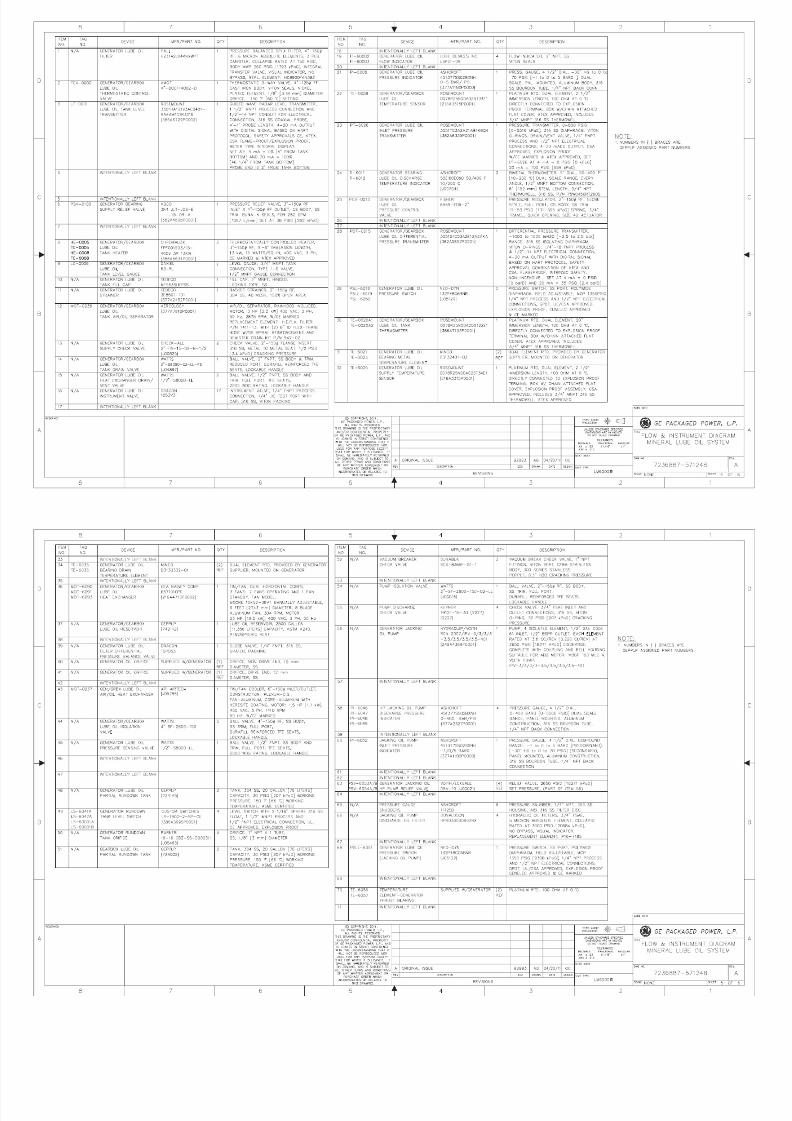
8/18/2019 71777896 - LM6000 Package Familiarization & Operations.pdf
http://slidepdf.com/reader/full/71777896-lm6000-package-familiarization-operationspdf 670/786
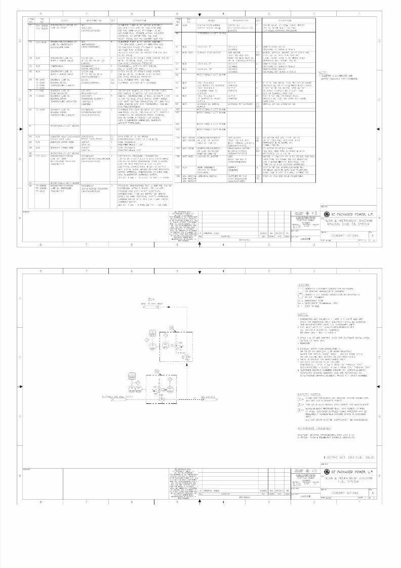
8/18/2019 71777896 - LM6000 Package Familiarization & Operations.pdf
http://slidepdf.com/reader/full/71777896-lm6000-package-familiarization-operationspdf 671/786
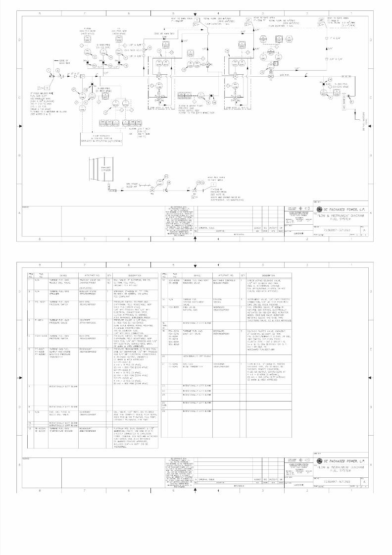
8/18/2019 71777896 - LM6000 Package Familiarization & Operations.pdf
http://slidepdf.com/reader/full/71777896-lm6000-package-familiarization-operationspdf 672/786
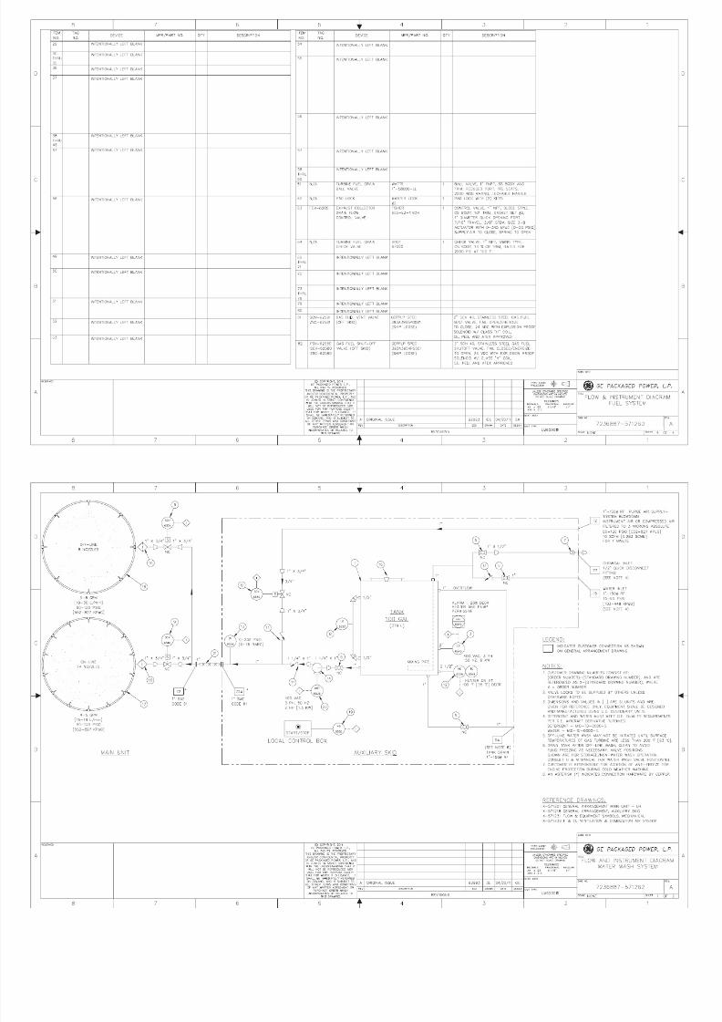
8/18/2019 71777896 - LM6000 Package Familiarization & Operations.pdf
http://slidepdf.com/reader/full/71777896-lm6000-package-familiarization-operationspdf 673/786

8/18/2019 71777896 - LM6000 Package Familiarization & Operations.pdf
http://slidepdf.com/reader/full/71777896-lm6000-package-familiarization-operationspdf 674/786
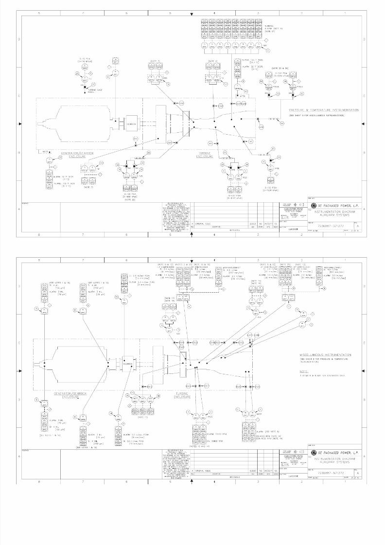
8/18/2019 71777896 - LM6000 Package Familiarization & Operations.pdf
http://slidepdf.com/reader/full/71777896-lm6000-package-familiarization-operationspdf 675/786

8/18/2019 71777896 - LM6000 Package Familiarization & Operations.pdf
http://slidepdf.com/reader/full/71777896-lm6000-package-familiarization-operationspdf 676/786
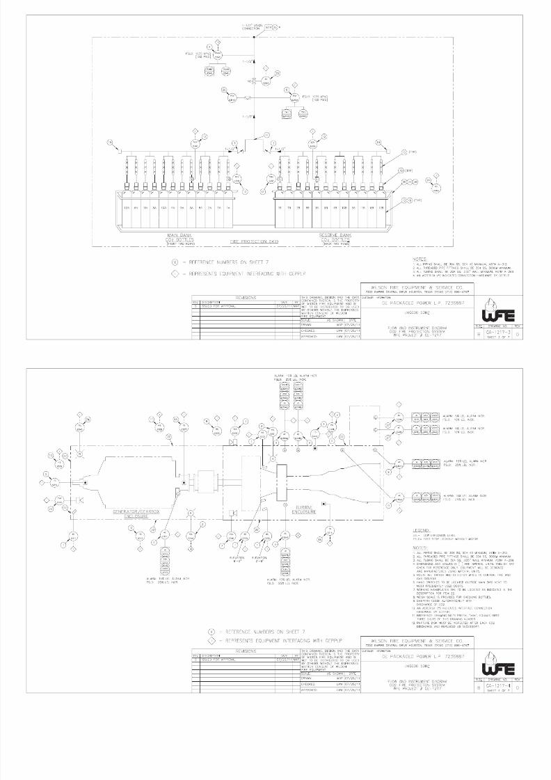
8/18/2019 71777896 - LM6000 Package Familiarization & Operations.pdf
http://slidepdf.com/reader/full/71777896-lm6000-package-familiarization-operationspdf 677/786
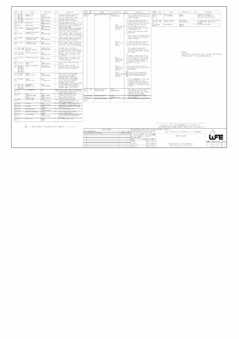
8/18/2019 71777896 - LM6000 Package Familiarization & Operations.pdf
http://slidepdf.com/reader/full/71777896-lm6000-package-familiarization-operationspdf 678/786
8/18/2019 71777896 - LM6000 Package Familiarization & Operations.pdf
http://slidepdf.com/reader/full/71777896-lm6000-package-familiarization-operationspdf 679/786

8/18/2019 71777896 - LM6000 Package Familiarization & Operations.pdf
http://slidepdf.com/reader/full/71777896-lm6000-package-familiarization-operationspdf 680/786

8/18/2019 71777896 - LM6000 Package Familiarization & Operations.pdf
http://slidepdf.com/reader/full/71777896-lm6000-package-familiarization-operationspdf 681/786

8/18/2019 71777896 - LM6000 Package Familiarization & Operations.pdf
http://slidepdf.com/reader/full/71777896-lm6000-package-familiarization-operationspdf 682/786

8/18/2019 71777896 - LM6000 Package Familiarization & Operations.pdf
http://slidepdf.com/reader/full/71777896-lm6000-package-familiarization-operationspdf 683/786

8/18/2019 71777896 - LM6000 Package Familiarization & Operations.pdf
http://slidepdf.com/reader/full/71777896-lm6000-package-familiarization-operationspdf 684/786
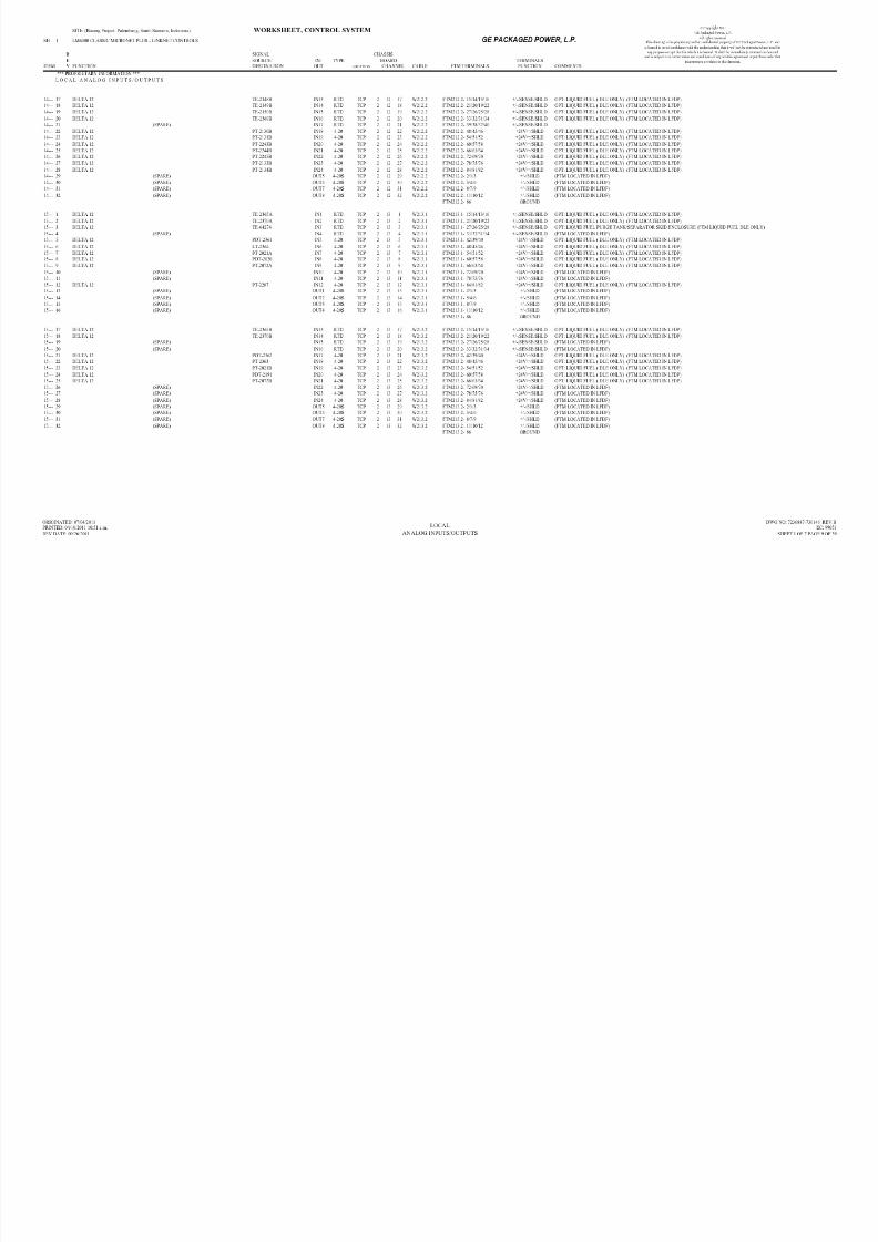
8/18/2019 71777896 - LM6000 Package Familiarization & Operations.pdf
http://slidepdf.com/reader/full/71777896-lm6000-package-familiarization-operationspdf 685/786
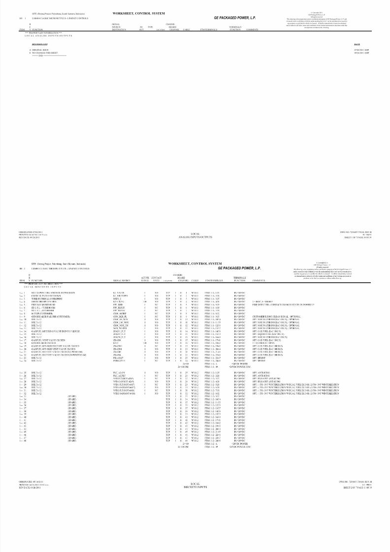
8/18/2019 71777896 - LM6000 Package Familiarization & Operations.pdf
http://slidepdf.com/reader/full/71777896-lm6000-package-familiarization-operationspdf 686/786
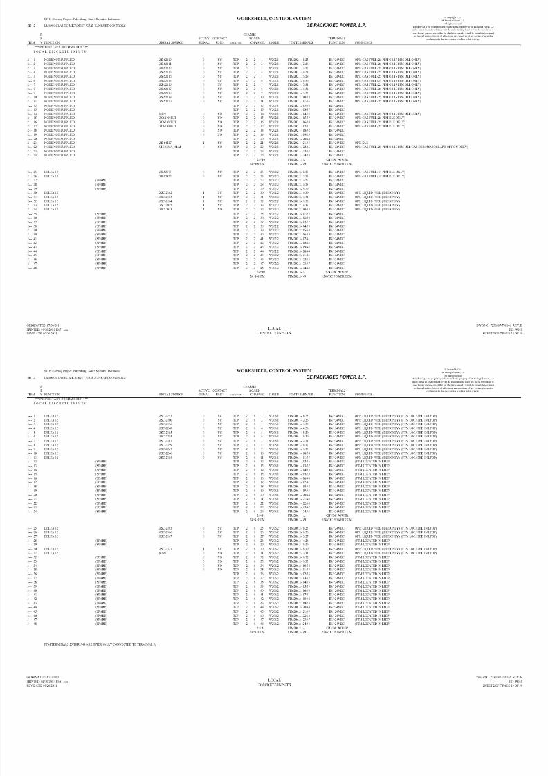
8/18/2019 71777896 - LM6000 Package Familiarization & Operations.pdf
http://slidepdf.com/reader/full/71777896-lm6000-package-familiarization-operationspdf 687/786

8/18/2019 71777896 - LM6000 Package Familiarization & Operations.pdf
http://slidepdf.com/reader/full/71777896-lm6000-package-familiarization-operationspdf 688/786

8/18/2019 71777896 - LM6000 Package Familiarization & Operations.pdf
http://slidepdf.com/reader/full/71777896-lm6000-package-familiarization-operationspdf 689/786
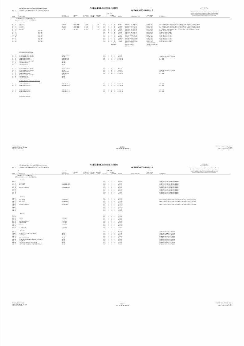
8/18/2019 71777896 - LM6000 Package Familiarization & Operations.pdf
http://slidepdf.com/reader/full/71777896-lm6000-package-familiarization-operationspdf 690/786
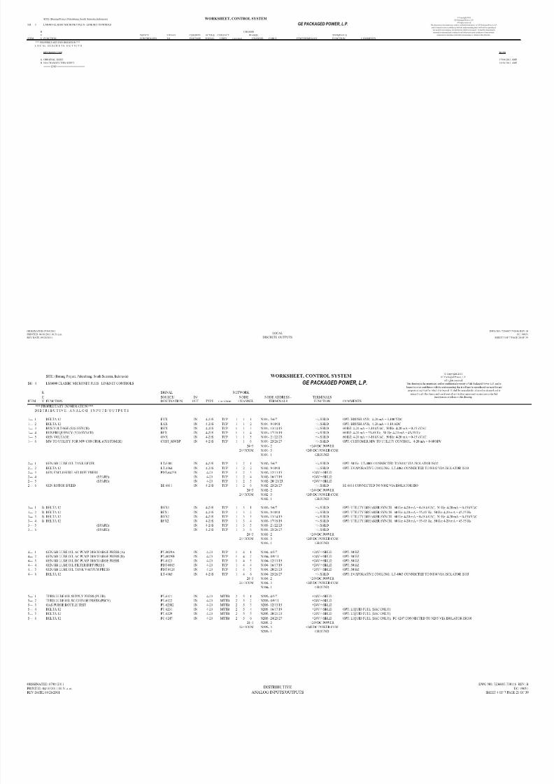
8/18/2019 71777896 - LM6000 Package Familiarization & Operations.pdf
http://slidepdf.com/reader/full/71777896-lm6000-package-familiarization-operationspdf 691/786

8/18/2019 71777896 - LM6000 Package Familiarization & Operations.pdf
http://slidepdf.com/reader/full/71777896-lm6000-package-familiarization-operationspdf 692/786

8/18/2019 71777896 - LM6000 Package Familiarization & Operations.pdf
http://slidepdf.com/reader/full/71777896-lm6000-package-familiarization-operationspdf 693/786

8/18/2019 71777896 - LM6000 Package Familiarization & Operations.pdf
http://slidepdf.com/reader/full/71777896-lm6000-package-familiarization-operationspdf 694/786
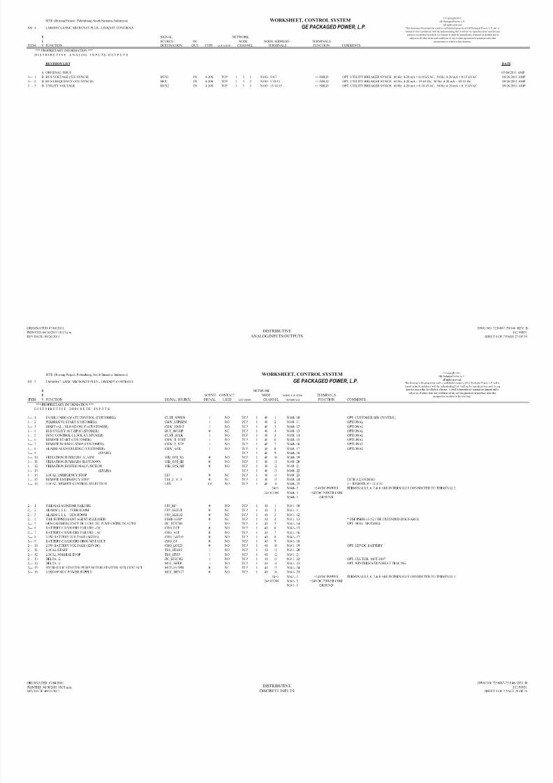
8/18/2019 71777896 - LM6000 Package Familiarization & Operations.pdf
http://slidepdf.com/reader/full/71777896-lm6000-package-familiarization-operationspdf 695/786

8/18/2019 71777896 - LM6000 Package Familiarization & Operations.pdf
http://slidepdf.com/reader/full/71777896-lm6000-package-familiarization-operationspdf 696/786
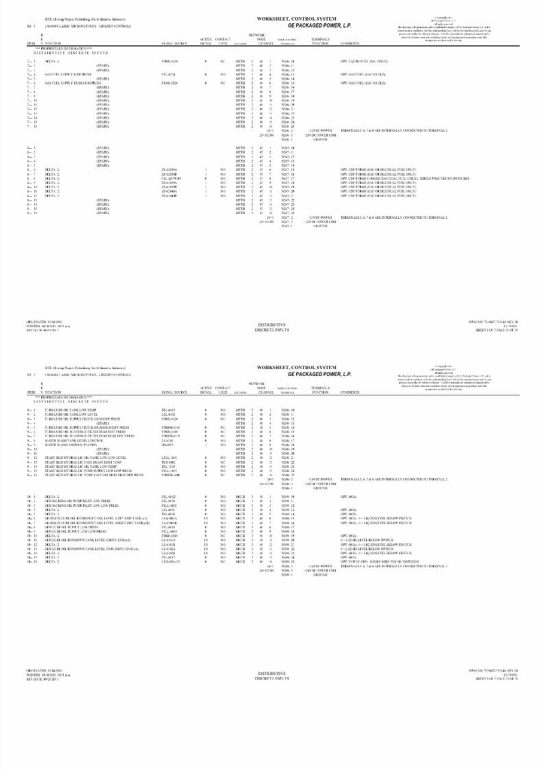
8/18/2019 71777896 - LM6000 Package Familiarization & Operations.pdf
http://slidepdf.com/reader/full/71777896-lm6000-package-familiarization-operationspdf 697/786
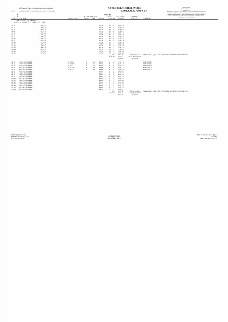
8/18/2019 71777896 - LM6000 Package Familiarization & Operations.pdf
http://slidepdf.com/reader/full/71777896-lm6000-package-familiarization-operationspdf 698/786
Tab B

8/18/2019 71777896 - LM6000 Package Familiarization & Operations.pdf
http://slidepdf.com/reader/full/71777896-lm6000-package-familiarization-operationspdf 699/786

8/18/2019 71777896 - LM6000 Package Familiarization & Operations.pdf
http://slidepdf.com/reader/full/71777896-lm6000-package-familiarization-operationspdf 700/786

8/18/2019 71777896 - LM6000 Package Familiarization & Operations.pdf
http://slidepdf.com/reader/full/71777896-lm6000-package-familiarization-operationspdf 701/786

8/18/2019 71777896 - LM6000 Package Familiarization & Operations.pdf
http://slidepdf.com/reader/full/71777896-lm6000-package-familiarization-operationspdf 702/786

8/18/2019 71777896 - LM6000 Package Familiarization & Operations.pdf
http://slidepdf.com/reader/full/71777896-lm6000-package-familiarization-operationspdf 703/786
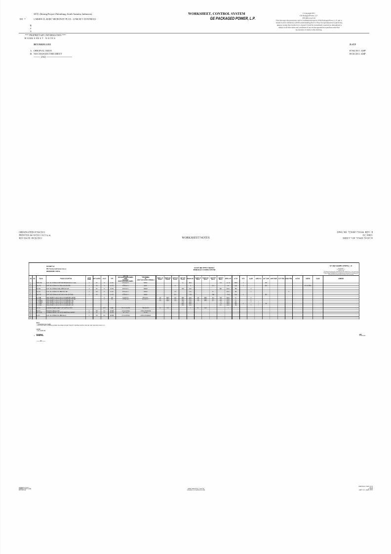
8/18/2019 71777896 - LM6000 Package Familiarization & Operations.pdf
http://slidepdf.com/reader/full/71777896-lm6000-package-familiarization-operationspdf 704/786

8/18/2019 71777896 - LM6000 Package Familiarization & Operations.pdf
http://slidepdf.com/reader/full/71777896-lm6000-package-familiarization-operationspdf 705/786

8/18/2019 71777896 - LM6000 Package Familiarization & Operations.pdf
http://slidepdf.com/reader/full/71777896-lm6000-package-familiarization-operationspdf 706/786
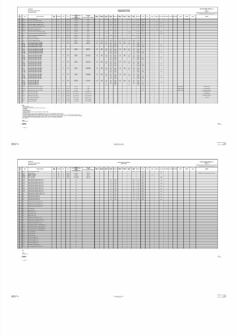
8/18/2019 71777896 - LM6000 Package Familiarization & Operations.pdf
http://slidepdf.com/reader/full/71777896-lm6000-package-familiarization-operationspdf 707/786
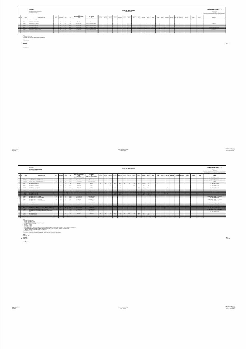
8/18/2019 71777896 - LM6000 Package Familiarization & Operations.pdf
http://slidepdf.com/reader/full/71777896-lm6000-package-familiarization-operationspdf 708/786
SITE: (Borang Project. Palembang, South Sumatra, Indonesia)
SH 1 LM6000 CLASSIC MICRONET PLUS - LINKNET CONTROLS GE PACKAGED POWER, L.P.
R SIGNAL CHASSIS
E SOURCE/ IN/ TYPE BOARD TERMINALS
ITEM V FUNCTION DESTINATION OUT LOCATION CHANNEL CABLE FUNCTION COMMENTS
*** PROPRIETARY INFORMATION ***
L O C A L A N A L O G I N P U T S / O U T P U T S
FTM TERMINALS
WORKSHEET, CONTROL SYSTEM © Copyright 2011
GE Packaged Power, L.P.
All rights reserved.
This drawing is the proprietary and/or confidential property of GE Packaged Power, L.P. and
is loaned in strict confidence with the understanding that it will not be reproduced nor used for
any purpose except that for which it is loaned. It shall be immediately returned on demand
and is subject to all other terms and conditions of any written agreement or purchase order that
incorporates or relates to this drawing.
11C- 1 NODE NOT SUPPLIED N/C TCP 1 2 3 W102.3 OPT: GAS FUEL (25 PPM DLE ONLY)
11C- 2 NODE NOT SUPPLIED N/C TCP 1 2 3 W102.3 OPT: GAS FUEL (25 PPM DLE ONLY)
11C- 3 NODE NOT SUPPLIED ZC62109+ IN/OUT RS485 TCP 1 2 3 W102.3 OPT: GAS FUEL (25 PPM DLE ONLY)
11C- 4 NODE NOT SUPPLIED N/C TCP 1 2 3 W102.3 OPT: GAS FUEL (25 PPM DLE ONLY)
11C- 5 NODE NOT SUPPLIED ZC62109 IN/OUT RS485 TCP 1 2 3 W102.3 OPT: GAS FUEL (25 PPM DLE ONLY)
11C- 6 NODE NOT SUPPLIED N/C TCP 1 2 3 W102.3 OPT: GAS FUEL (25 PPM DLE ONLY)
11C- 7 NODE NOT SUPPLIED N/C TCP 1 2 3 W102.3 OPT: GAS FUEL (25 PPM DLE ONLY)
11C- 8 NODE NOT SUPPLIED ZC62109- IN/OUT RS485 TCP 1 2 3 W102.3 OPT: GAS FUEL (25 PPM DLE ONLY)
11C- 9 NODE NOT SUPPLIED N/C TCP 1 2 3 W102.3 OPT: GAS FUEL (25 PPM DLE ONLY)
12A- 1 NODE NOT SUPPLIED N/C TCP 2 9 1 W209.1
12A- 2 NODE NOT SUPPLIED N/C TCP 2 9 1 W209.1
12A- 3 NODE NOT SUPPLIED ZC62568+ IN/OUT RS485 TCP 2 9 1 W209.112A- 4 NODE NOT SUPPLIED N/C TCP 2 9 1 W209.1
12A- 5 NODE NOT SUPPLIED ZC62568 IN/OUT RS485 TCP 2 9 1 W209.1
12A- 6 NODE NOT SUPPLIED N/C TCP 2 9 1 W209.1
12A- 7 NODE NOT SUPPLIED N/C TCP 2 9 1 W209.1
12A- 8 NODE NOT SUPPLIED ZC62568- IN/OUT RS485 TCP 2 9 1 W209.1
12A- 9 NODE NOT SUPPLIED N/C TCP 2 9 1 W209.1
12B- 1 N/C TCP 2 9 2 W209.2
12B- 2 N/C TCP 2 9 2 W209.2
12B- 3 (SPARE) IN/OUT RS485 TCP 2 9 2 W209.2
12B- 4 N/C TCP 2 9 2 W209.2
12B- 5 (SPARE) IN/OUT RS485 TCP 2 9 2 W209.2
12B- 6 N/C TCP 2 9 2 W209.2
12B- 7 N/C TCP 2 9 2 W209.2
12B- 8 (SPARE) IN/OUT RS485 TCP 2 9 2 W209.2
12B- 9 N/C TCP 2 9 2 W209.2
12C- 1 N/C TCP 2 9 3 W209.3
12C- 2 N/C TCP 2 9 3 W209.3
12C- 3 (SPARE) IN/OUT RS485 TCP 2 9 3 W209.3
12C- 4 N/C TCP 2 9 3 W209.3
12C- 5 (SPARE) IN/OUT RS485 TCP 2 9 3 W209.3
12C- 6 N/C TCP 2 9 3 W209.3
12C- 7 N/C TCP 2 9 3 W209.3
12C- 8 (SPARE) IN/OUT RS485 TCP 2 9 3 W209.3
12C- 9 N/C TCP 2 9 3 W209.3
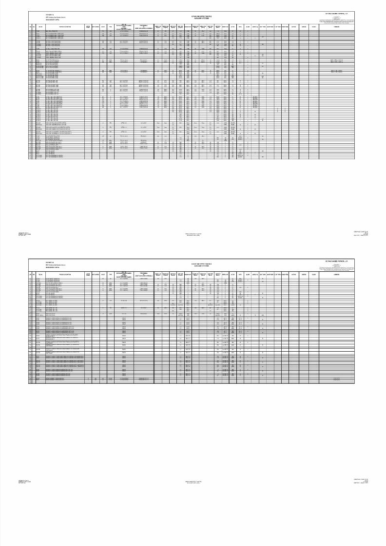
8/18/2019 71777896 - LM6000 Package Familiarization & Operations.pdf
http://slidepdf.com/reader/full/71777896-lm6000-package-familiarization-operationspdf 709/786
ORIGINATED: 07/04/2011
PRINTED: 04/10/2011 10:51 a.m.
REV DATE: 09/26/2011
LOCAL
ANALOG INPUTS/OUTPUTS
DWG NO: 7236887
SHEET 1 OF

8/18/2019 71777896 - LM6000 Package Familiarization & Operations.pdf
http://slidepdf.com/reader/full/71777896-lm6000-package-familiarization-operationspdf 710/786
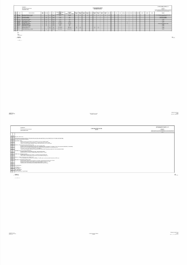
8/18/2019 71777896 - LM6000 Package Familiarization & Operations.pdf
http://slidepdf.com/reader/full/71777896-lm6000-package-familiarization-operationspdf 711/786
SITE: (Borang Project. Palembang, South Sumatra, Indonesia)
SH 1 LM6000 CLASSIC MICRONET PLUS - LINKNET CONTROLS GE PACKAGED POWER, L.P.
R SIGNAL CHASSIS
E SOURCE/ IN/ TYPE BOARD TERMINALS
ITEM V FUNCTION DESTINATION OUT LOCATION CHANNEL CABLE FUNCTION COMMENTS
*** PROPRIETARY INFORMATION ***
L O C A L A N A L O G I N P U T S / O U T P U T S
FTM TERMINALS
WORKSHEET, CONTROL SYSTEM © Copyright 2011
GE Packaged Power, L.P.
All rights reserved.
This drawing is the proprietary and/or confidential property of GE Packaged Power, L.P. and
is loaned in strict confidence with the understanding that it will not be reproduced nor used for
any purpose except that for which it is loaned. It shall be immediately returned on demand
and is subject to all other terms and conditions of any written agreement or purchase order that
incorporates or relates to this drawing.
REVISION LIST DA
A ORIGINAL ISSUE 07/
B NO CHANGES THIS SHEET 09/
===== END ====================
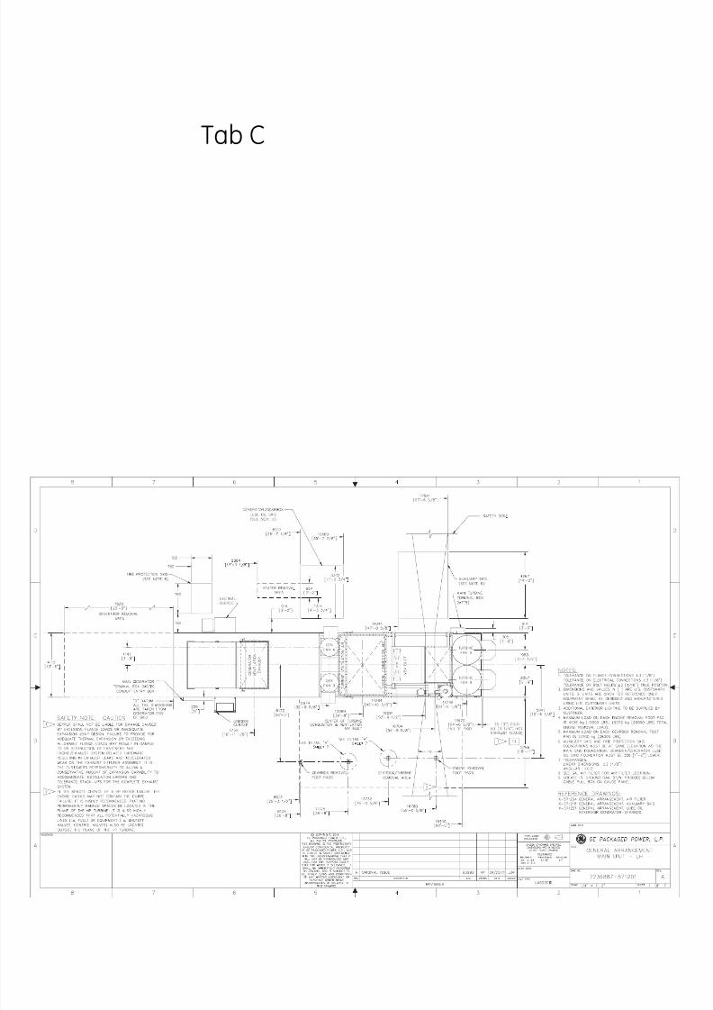
8/18/2019 71777896 - LM6000 Package Familiarization & Operations.pdf
http://slidepdf.com/reader/full/71777896-lm6000-package-familiarization-operationspdf 712/786
ORIGINATED: 07/04/2011
PRINTED: 04/10/2011 10:51 a.m.
REV DATE: 09/26/2011
LOCAL
ANALOG INPUTS/OUTPUTS
DWG NO: 7236887
SHEET 1 OF 7

8/18/2019 71777896 - LM6000 Package Familiarization & Operations.pdf
http://slidepdf.com/reader/full/71777896-lm6000-package-familiarization-operationspdf 713/786

8/18/2019 71777896 - LM6000 Package Familiarization & Operations.pdf
http://slidepdf.com/reader/full/71777896-lm6000-package-familiarization-operationspdf 714/786
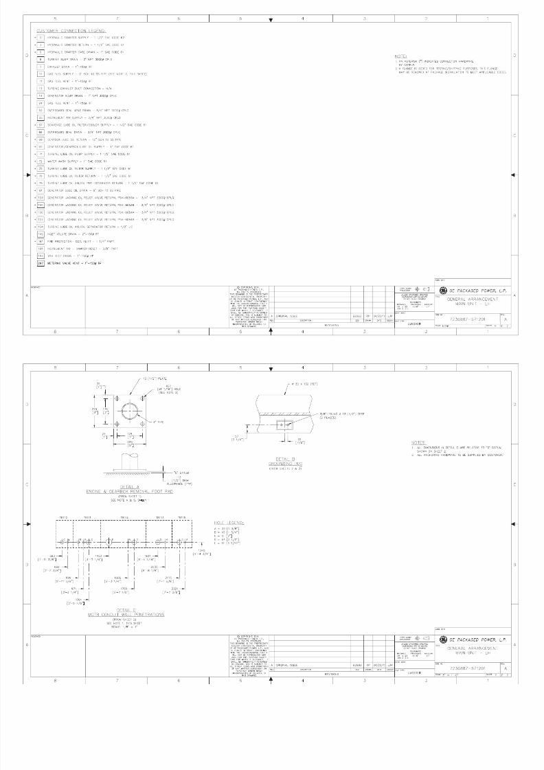
8/18/2019 71777896 - LM6000 Package Familiarization & Operations.pdf
http://slidepdf.com/reader/full/71777896-lm6000-package-familiarization-operationspdf 715/786
SITE: (Borang Project. Palembang, South Sumatra, Indonesia) WORKSHEET, CONTROL SYSTEM
SH 2 LM6000 CLASSIC MICRONET PLUS - LINKNET CONTROLS GE PACKAGED POWER, L.P.
R CHASSIS
E ACTIVE CONTACT BOARD TERMINALS
ITEM V FUNCTION SIGNAL SOURCE SIGNAL USED LOCATION CHANNEL CABLE FUNCTION COMMENTS
*** PROPRIETARY INFORMATION ***
L O C A L D I S C R E T E I N P U T S
FTM TERMINALS
© Copyright 2011
GE Packaged Power, L.P.
All rights reserved.
This drawing is the proprietary and/or confidential property of GE Packaged Power, L.P
and is loaned in strict confidence wi th the understanding that it will not be reproduced n
used for any purpose except that for which it is loaned. It shall be immediately returned
on demand and is subject to all other terms and conditions of any written agreement or
purchase order that incorporates or relates to this drawing.
REVISION LIST DAT
A ORIGINAL ISSUE 07/04
B NO CHANGES THIS SHEET 09/26
===== END ====================

8/18/2019 71777896 - LM6000 Package Familiarization & Operations.pdf
http://slidepdf.com/reader/full/71777896-lm6000-package-familiarization-operationspdf 716/786
ORIGINATED: 07/04/2011
PRINTED: 04/10/2011 10:51 a.m.
REV DATE: 09/26/2011
LOCAL
DISCRETE INPUTS
DWG NO: 7236887-
SHEET 2 OF 7

8/18/2019 71777896 - LM6000 Package Familiarization & Operations.pdf
http://slidepdf.com/reader/full/71777896-lm6000-package-familiarization-operationspdf 717/786
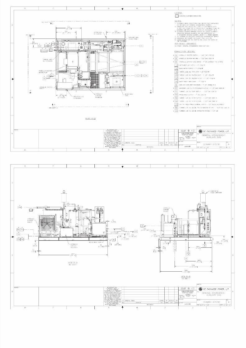
8/18/2019 71777896 - LM6000 Package Familiarization & Operations.pdf
http://slidepdf.com/reader/full/71777896-lm6000-package-familiarization-operationspdf 718/786
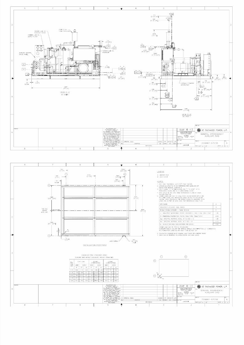
8/18/2019 71777896 - LM6000 Package Familiarization & Operations.pdf
http://slidepdf.com/reader/full/71777896-lm6000-package-familiarization-operationspdf 719/786
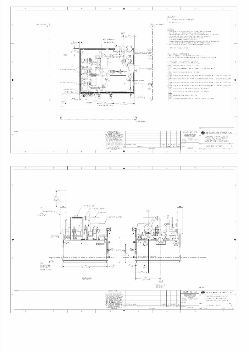
8/18/2019 71777896 - LM6000 Package Familiarization & Operations.pdf
http://slidepdf.com/reader/full/71777896-lm6000-package-familiarization-operationspdf 720/786
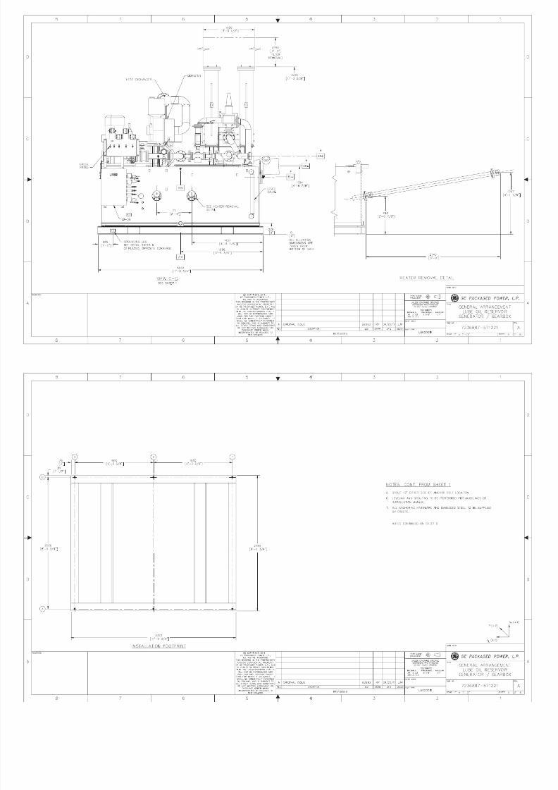
8/18/2019 71777896 - LM6000 Package Familiarization & Operations.pdf
http://slidepdf.com/reader/full/71777896-lm6000-package-familiarization-operationspdf 721/786
SITE: (Borang Project. Palembang, South Sumatra, Indonesia) WORKSHEET, CONTROL SYSTEM
SH 3 LM6000 CLASSIC MICRONET PLUS - LINKNET CONTROLS GE PACKAGED POWER, L.P.
R CHASSIS
E DEVICE SIGNAL CONTROL ACTIVE CONTACT BOARD TERMINALS
ITEM V FUNCTION CONTROLLED TO VOLTAGE SIGNAL USED LOCATION CHANNEL CABLE FUNCTION COMMENTS
*** PROPRIETARY INFORMATION ***
L O C A L D I S C R E T E O U T P U T S
FTM TERMINALS
© Copyright 2011
GE Packaged Power, L.P.
All rights reserved.
This drawing is the proprietary and/or confidential property of GE Packaged Power, L.P.
and is loaned in strict confidence with the understanding that it will not be reproduced
nor used for any purpose except that for which it is loaned. It shall be immediately
returned on demand and is subject to all other terms and conditions of any written
agreement or purchase order that incorporates or relates to this drawing.
REVISION LIST DATE
A ORIGINAL ISSUE 07/04/2
B NO CHANGES THIS SHEET 09/26/2
===== END ====================

8/18/2019 71777896 - LM6000 Package Familiarization & Operations.pdf
http://slidepdf.com/reader/full/71777896-lm6000-package-familiarization-operationspdf 722/786
ORIGINATED: 07/04/2011
PRINTED: 04/10/2011 10:51 a.m.
REV DATE: 09/26/2011
LOCAL
DISCRETE OUTPUTS
DWG NO: 72368
SHEET 3 O

8/18/2019 71777896 - LM6000 Package Familiarization & Operations.pdf
http://slidepdf.com/reader/full/71777896-lm6000-package-familiarization-operationspdf 723/786

8/18/2019 71777896 - LM6000 Package Familiarization & Operations.pdf
http://slidepdf.com/reader/full/71777896-lm6000-package-familiarization-operationspdf 724/786

8/18/2019 71777896 - LM6000 Package Familiarization & Operations.pdf
http://slidepdf.com/reader/full/71777896-lm6000-package-familiarization-operationspdf 725/786
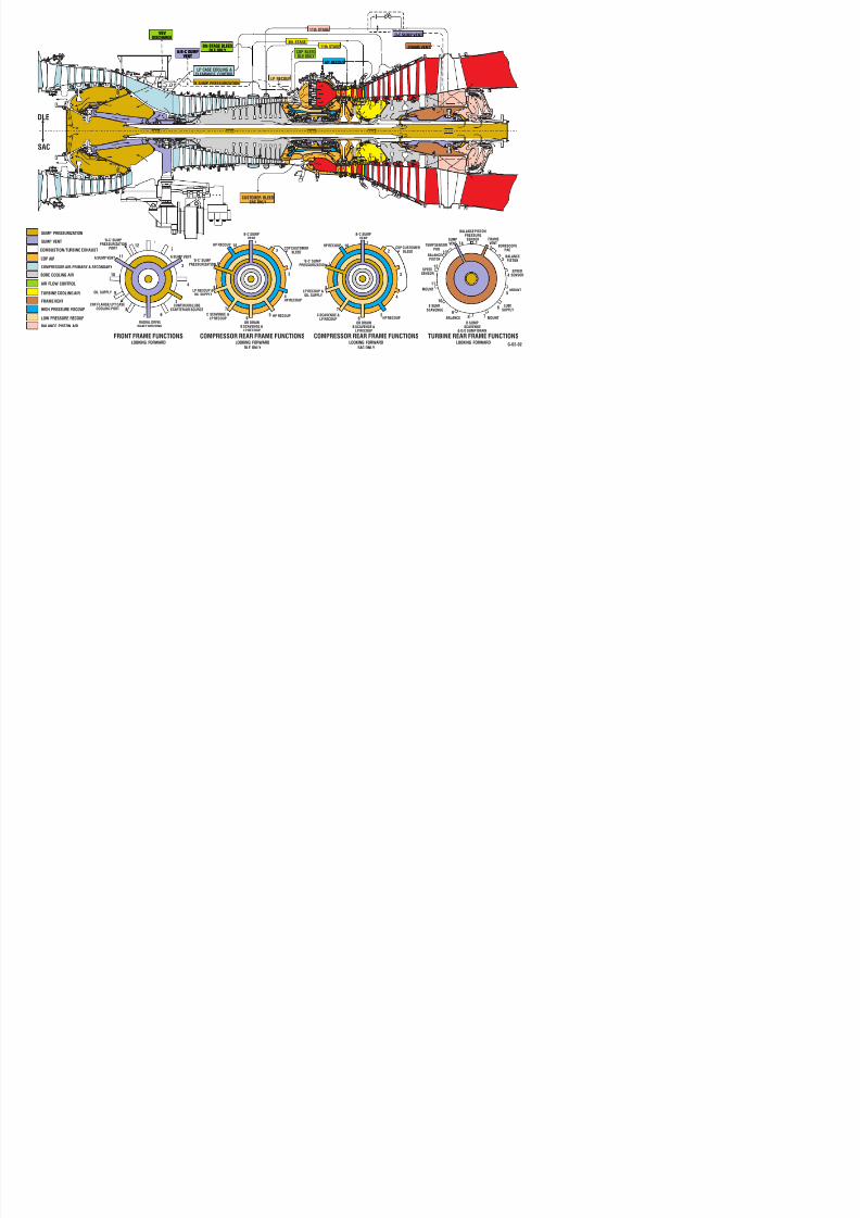
8/18/2019 71777896 - LM6000 Package Familiarization & Operations.pdf
http://slidepdf.com/reader/full/71777896-lm6000-package-familiarization-operationspdf 726/786

8/18/2019 71777896 - LM6000 Package Familiarization & Operations.pdf
http://slidepdf.com/reader/full/71777896-lm6000-package-familiarization-operationspdf 727/786

8/18/2019 71777896 - LM6000 Package Familiarization & Operations.pdf
http://slidepdf.com/reader/full/71777896-lm6000-package-familiarization-operationspdf 728/786
SITE: (Borang Project. Palembang, South Sumatra, Indonesia) WORKSHEET, CONTROL SYSTEM
SH 4 LM6000 CLASSIC MICRONET PLUS - LINKNET CONTROLS GE PACKAGED POWER, L.P.
R SIGNAL NETWORK
E SOURCE/ IN/ NODE TERMINALS
ITEM V FUNCTION DESTINATION OUT TYPE LOCATION CHANNEL FUNCTION COMMENTS
*** PROPRIETARY INFORMATION ***D I S T R I B U T I V E A N A L O G I N P U T S / O U T P U T S
NODE ADDRESS -
TERMINALS
© Copyright 2011
GE Packaged Power, L.P.
All rights reserved.
This drawing is the proprietary and/or confidential property of GE Packaged Power, L.P. and is
loaned in strict confidence with the understanding that it will not be reproduced nor used for any
purpose except that for which it is loaned. It shall be immediately returned on demand and is
subject to all other terms and conditions of any written agreement or purchase order that
incorporates or relates to this drawing.
REVISION LIST DA
A ORIGINAL ISSUE 07/
3--- 1 B BUS VOLTAGE (52U SYNCH) BVX1 IN 4-20S TCP 1 3 1 N103- 5/6/7 +/-/SHLD OPT: UTILITY BREAKER SYNCH. 60 Hz: 4-20 mA = 0-18 kVAC, 50 Hz: 4-20 mA = 0-15 kVAC 09/
3--- 2 B BUS FREQUENCY (52U SYNCH) BFX1 IN 4-20S TCP 1 3 2 N103- 9/10/11 +/-/SHLD OPT: UTILITY BREAKER SYNCH. 60 Hz: 4-20 mA = 55-65 Hz, 50 Hz: 4-20 mA = 45-55 Hz 09/
3--- 3 B UTILITY VOLTAGE BVX2 IN 4-20S TCP 1 3 3 N103- 13/14/15 +/-/SHLD OPT: UTILITY BREAKER SYNCH. 60 Hz: 4-20 mA = 0-18 kVAC, 50 Hz: 4-20 mA = 0-15 kVAC 09/

8/18/2019 71777896 - LM6000 Package Familiarization & Operations.pdf
http://slidepdf.com/reader/full/71777896-lm6000-package-familiarization-operationspdf 729/786
ORIGINATED: 07/04/2011
PRINTED: 04/10/2011 10:51 a.m.
REV DATE: 09/26/2011
DISTRIBUTIVE
ANALOG INPUTS/OUTPUTS
DWG NO: 7236887-7
SHEET 4 OF 7 P

8/18/2019 71777896 - LM6000 Package Familiarization & Operations.pdf
http://slidepdf.com/reader/full/71777896-lm6000-package-familiarization-operationspdf 730/786

8/18/2019 71777896 - LM6000 Package Familiarization & Operations.pdf
http://slidepdf.com/reader/full/71777896-lm6000-package-familiarization-operationspdf 731/786

8/18/2019 71777896 - LM6000 Package Familiarization & Operations.pdf
http://slidepdf.com/reader/full/71777896-lm6000-package-familiarization-operationspdf 732/786

8/18/2019 71777896 - LM6000 Package Familiarization & Operations.pdf
http://slidepdf.com/reader/full/71777896-lm6000-package-familiarization-operationspdf 733/786

8/18/2019 71777896 - LM6000 Package Familiarization & Operations.pdf
http://slidepdf.com/reader/full/71777896-lm6000-package-familiarization-operationspdf 734/786
SITE: (Borang Project. Palembang, South Sumatra, Indonesia) WORKSHEET, CONTROL SYSTEM
SH 5 LM6000 CLASSIC MICRONET PLUS - LINKNET CONTROLS GE PACKAGED POWER, L.P.
R NETWORK
E ACTIVE CONTACT NODE TERMINALS
ITEM V FUNCTION SIGNAL SOURCE SIGNAL USED LOCATION CHANNEL FUNCTION COMMENTS
*** PROPRIETARY INFORMATION ***
D I S T R I B U T I V E D I S C R E T E I N P U T S
NODE ADDRESS-
TERMINALS
© Copyright 2011
GE Packaged Power, L.P.
All rights reserved.
This drawing is the proprietary and/or confidential property of GE Packaged Power, L.P. and is
loaned in strict confidence with the understanding that it will not be reproduced nor used for any
purpose except that for which it is loaned. It shall be immediately returned on demand and is
subject to all other terms and conditions of any written agreement or purchase order that
incorporates or relates to this drawing.
11-- 1 (SPARE) MGTB 3 50 1 N350- 10
11-- 2 (SPARE) MGTB 3 50 2 N350- 11
11-- 3 (SPARE) MGTB 3 50 3 N350- 12
11-- 4 (SPARE) MGTB 3 50 4 N350- 13
11-- 5 (SPARE) MGTB 3 50 5 N350- 14
11-- 6 (SPARE) MGTB 3 50 6 N350- 15
11-- 7 (SPARE) MGTB 3 50 7 N350- 16
11-- 8 (SPARE) MGTB 3 50 8 N350- 17
11-- 9 (SPARE) MGTB 3 50 9 N350- 18
11-- 10 (SPARE) MGTB 3 50 10 N350- 19
11-- 11 (SPARE) MGTB 3 50 11 N350- 20
11-- 12 (SPARE) MGTB 3 50 12 N350- 21
11-- 13 (SPARE) MGTB 3 50 13 N350- 2211-- 14 (SPARE) MGTB 3 50 14 N350- 23
11-- 15 (SPARE) MGTB 3 50 15 N350- 24
11-- 16 (SPARE) MGTB 3 50 16 N350- 25
24+1 N350- 2 +24VDC POWER TERMINALS 5, 6, 7 & 8 ARE INTERNALLY CONNECTED TO TERMINAL 2
24+1COM N350- 3 +24VDC POWER COM
N350- 1 GROUND
12-- 1 NODE NOT SUPPLIED ZS-68300A 1 NO JB86A 4 51 1 N451- 10 OPT: CLUTCH
12-- 2 NODE NOT SUPPLIED ZS-68300B 1 NO JB86A 4 51 2 N451- 11 OPT: CLUTCH
12-- 3 NODE NOT SUPPLIED ZS-68301A 1 NO JB86A 4 51 3 N451- 12 OPT: CLUTCH
12-- 4 NODE NOT SUPPLIED ZS-68301B 1 NO JB86A 4 51 4 N451- 13 OPT: CLUTCH
12-- 5 NODE NOT SUPPLIED ZS-68302 1 NO JB86A 4 51 5 N451- 14 OPT: CLUTCH
12-- 6 NODE NOT SUPPLIED JB86A 4 51 6 N451- 15
12-- 7 NODE NOT SUPPLIED JB86A 4 51 7 N451- 1612-- 8 NODE NOT SUPPLIED JB86A 4 51 8 N451- 17
12-- 9 NODE NOT SUPPLIED JB86A 4 51 9 N451- 18
12-- 10 NODE NOT SUPPLIED JB86A 4 51 10 N451- 19
12-- 11 NODE NOT SUPPLIED JB86A 4 51 11 N451- 20
12-- 12 NODE NOT SUPPLIED JB86A 4 51 12 N451- 21
12-- 13 NODE NOT SUPPLIED JB86A 4 51 13 N451- 22
12-- 14 NODE NOT SUPPLIED JB86A 4 51 14 N451- 23
12-- 15 NODE NOT SUPPLIED JB86A 4 51 15 N451- 24
12-- 16 NODE NOT SUPPLIED JB86A 4 51 16 N451- 25
24+1 N451- 2 +24VDC POWER TERMINALS 5, 6, 7 & 8 ARE INTERNALLY CONNECTED TO TERMINAL 2
24+1COM N451- 3 +24VDC POWER COM
N451- 1 GROUND

8/18/2019 71777896 - LM6000 Package Familiarization & Operations.pdf
http://slidepdf.com/reader/full/71777896-lm6000-package-familiarization-operationspdf 735/786
ORIGINATED: 07/04/2011
PRINTED: 04/10/2011 10:51 a.m.
REV DATE: 09/26/2011
DISTRIBUTIVE
DISCRETE INPUTS
DWG NO: 7236887-7
SHEET 5 OF 7 P
SITE: (Borang Project. Palembang, South Sumatra, Indonesia) WORKSHEET, CONTROL SYSTEM
SH 5 LM6000 CLASSIC MICRONET PLUS - LINKNET CONTROLS GE PACKAGED POWER, L.P.
R NETWORK
E ACTIVE CONTACT NODE TERMINALS
ITEM V FUNCTION SIGNAL SOURCE SIGNAL USED LOCATION CHANNEL FUNCTION COMMENTS
*** PROPRIETARY INFORMATION ***
D I S T R I B U T I V E D I S C R E T E I N P U T S
NODE ADDRESS-
TERMINALS
© Copyright 2011
GE Packaged Power, L.P.
All rights reserved.
This drawing is the proprietary and/or confidential property of GE Packaged Power, L.P. and is
loaned in strict confidence with the understanding that it will not be reproduced nor used for any
purpose except that for which it is loaned. It shall be immediately returned on demand and is
subject to all other terms and conditions of any written agreement or purchase order that
incorporates or relates to this drawing.
13-- 1 NODE NOT SUPPLIED ZSC-4240 1 NO JB40 2 52 1 N252- 10 OPT: EXHAUST ANTI-ICING
13-- 2 NODE NOT SUPPLIED ZSO-4240 1 NO JB40 2 52 2 N252- 11 OPT: EXHAUST ANTI-ICING
13-- 3 NODE NOT SUPPLIED ZSC-4241 1 NO JB40 2 52 3 N252- 12 OPT: EXHAUST ANTI-ICING
13-- 4 NODE NOT SUPPLIED ZSO-4241 1 NO JB40 2 52 4 N252- 13 OPT: EXHAUST ANTI-ICING
13-- 5 NODE NOT SUPPLIED JB40 2 52 5 N252- 14
13-- 6 NODE NOT SUPPLIED JB40 2 52 6 N252- 15
13-- 7 NODE NOT SUPPLIED JB40 2 52 7 N252- 16
13-- 8 NODE NOT SUPPLIED JB40 2 52 8 N252- 17
13-- 9 NODE NOT SUPPLIED JB40 2 52 9 N252- 18
13-- 10 NODE NOT SUPPLIED JB40 2 52 10 N252- 19
13-- 11 NODE NOT SUPPLIED JB40 2 52 11 N252- 20
13-- 12 NODE NOT SUPPLIED JB40 2 52 12 N252- 21
13-- 13 NODE NOT SUPPLIED JB40 2 52 13 N252- 2213-- 14 NODE NOT SUPPLIED JB40 2 52 14 N252- 23
13-- 15 NODE NOT SUPPLIED JB40 2 52 15 N252- 24
13-- 16 NODE NOT SUPPLIED JB40 2 52 16 N252- 25
24+1 N252- 2 +24VDC POWER TERMINALS 5, 6, 7 & 8 ARE INTERNALLY CONNECTED TO TERMINAL 2
24+1COM N252- 3 +24VDC POWER COM
N252- 1 GROUND
NODES TERMINALS 28, 29 & 30 ARE COMMUNICATION DATA "B", DATA "A" & SHIELD, RESPECTIVELY.
NODES 1 THRU 39 = ANALOG
NODES 40 THRU 59 = DISCRETE INPUTS NODES 60 THRU 79 = DISCRETE OUTPUTS

8/18/2019 71777896 - LM6000 Package Familiarization & Operations.pdf
http://slidepdf.com/reader/full/71777896-lm6000-package-familiarization-operationspdf 736/786
ORIGINATED: 07/04/2011
PRINTED: 04/10/2011 10:51 a.m.
REV DATE: 09/26/2011
DISTRIBUTIVE
DISCRETE INPUTS
DWG NO: 7236887-7
SHEET 5 OF 7 P
SITE: (Borang Project. Palembang, South Sumatra, Indonesia) WORKSHEET, CONTROL SYSTEM
SH 5 LM6000 CLASSIC MICRONET PLUS - LINKNET CONTROLS GE PACKAGED POWER, L.P.
R NETWORK
E ACTIVE CONTACT NODE TERMINALS
ITEM V FUNCTION SIGNAL SOURCE SIGNAL USED LOCATION CHANNEL FUNCTION COMMENTS
*** PROPRIETARY INFORMATION ***
D I S T R I B U T I V E D I S C R E T E I N P U T S
NODE ADDRESS-
TERMINALS
© Copyright 2011
GE Packaged Power, L.P.
All rights reserved.
This drawing is the proprietary and/or confidential property of GE Packaged Power, L.P. and is
loaned in strict confidence with the understanding that it will not be reproduced nor used for any
purpose except that for which it is loaned. It shall be immediately returned on demand and is
subject to all other terms and conditions of any written agreement or purchase order that
incorporates or relates to this drawing.
REVISION LIST DA
A ORIGINAL ISSUE 07/0
B NO CHANGES THIS SHEET 09/2
===== END ====================

8/18/2019 71777896 - LM6000 Package Familiarization & Operations.pdf
http://slidepdf.com/reader/full/71777896-lm6000-package-familiarization-operationspdf 737/786
ORIGINATED: 07/04/2011
PRINTED: 04/10/2011 10:51 a.m.
REV DATE: 09/26/2011
DISTRIBUTIVE
DISCRETE INPUTS
DWG NO: 7236887-7
SHEET 5 OF 7 P
SITE: (Borang Project. Palembang, South Sumatra, Indonesia) WORKSHEET, CONTROL SYSTEM
SH 6 LM6000 CLASSIC MICRONET PLUS - LINKNET CONTROLS GE PACKAGED POWER, L.P.
R NETWORK
E DEVICE SIGNAL CONTROL ACTIVE CONTACT NODE TERMINALS
ITEM V FUNCTION CONTROLLED TO VOLTAGE SIGNAL USED LOCATION CHANNEL FUNCTION COMMENTS
*** PROPRIETARY INFORMATION ***
D I S T R I B U T I V E D I S C R E T E O U T P U T S
1--- 1 NODE NOT SUPPLIED MOV-4240-1 ANTI-ICING SKID 24 VDC 1 NO JB40 2 60 1 N260- 4/5/6 NO/COM/NC OPT: EXHAUST ANTI-ICING. 1 = OPEN VALVE
1--- 2 NODE NOT SUPPLIED MOV-4240-2 ANTI-ICING SKID 24 VDC 1 NO JB40 2 60 2 N260- 7/8/9 NO/COM/NC OPT: EXHAUST ANTI-ICING. 1 = CLOSE VALVE
1--- 3 NODE NOT SUPPLIED MOV-4241-1 ANTI-ICING SKID 24 VDC 1 NO JB40 2 60 3 N260- 10/11/12 NO/COM/NC OPT: EXHAUST ANTI-ICING. 1 = OPEN VALVE
1--- 4 NODE NOT SUPPLIED MOV-4241-2 ANTI-ICING SKID 24 VDC 1 NO JB40 2 60 4 N260- 13/14/15 NO/COM/NC OPT: EXHAUST ANTI-ICING. 1 = CLOSE VALVE
1--- 5 NODE NOT SUPPLIED MOV-4242-1 ANTI-ICING SKID 24 VDC 1 NO JB40 2 60 5 N260- 16/17/18 NO/COM/NC OPT: EXHAUST ANTI-ICING. 1 = OPEN VALVE
1--- 6 NODE NOT SUPPLIED MOV-4242-2 ANTI-ICING SKID 24 VDC 1 NO JB40 2 60 6 N260- 19/20/21 NO/COM/NC OPT: EXHAUST ANTI-ICING. 1 = CLOSE VALVE
1--- 7 NODE NOT SUPPLIED JB40 2 60 7 N260- 22/23/24 NO/COM/NC
1--- 8 NODE NOT SUPPLIED JB40 2 60 8 N260- 25/26/27 NO/COM/NC
24+1 N260- 2 +24VDC POWER
24+1COM N260- 3 +24VDC POWER COM
N260- 1 GROUND
NODES TERMINALS 28, 29 & 30 ARE COMMUNICATION DATA "B", DATA "A" & SHIELD, RESPECTIVELY.
NODES 1 THRU 39 = ANALOG
NODES 40 THRU 59 = DISCRETE INPUTS
NODES 60 THRU 79 = DISCRETE OUTPUTS
NODE ADDRESS-
TERMINALS
© Copyright 2011
GE Packaged Power, L.P.
All rights reserved.
This drawing is the proprietary and/or confidential property of GE Packaged Power, L.P. and
is loaned in strict confidence with the understanding that it will not be reproduced nor used for
any purpose except that for which it is loaned. It shall be immediately returned on demand
and is subject to all other terms and conditions of any written agreement or purchase order that
incorporates or relates to this drawing.

8/18/2019 71777896 - LM6000 Package Familiarization & Operations.pdf
http://slidepdf.com/reader/full/71777896-lm6000-package-familiarization-operationspdf 738/786
ORIGINATED: 07/04/2011
PRINTED: 04/10/2011 10:51 a.m.
REV DATE: 09/26/2011
DISTRIBUTIVE
DISCRETE OUTPUTS
DWG NO: 7236887
SHEET 6 OF 7
SITE: (Borang Project. Palembang, South Sumatra, Indonesia) WORKSHEET, CONTROL SYSTEM
SH 6 LM6000 CLASSIC MICRONET PLUS - LINKNET CONTROLS GE PACKAGED POWER, L.P.
R NETWORK
E DEVICE SIGNAL CONTROL ACTIVE CONTACT NODE TERMINALS
ITEM V FUNCTION CONTROLLED TO VOLTAGE SIGNAL USED LOCATION CHANNEL FUNCTION COMMENTS
*** PROPRIETARY INFORMATION ***
D I S T R I B U T I V E D I S C R E T E O U T P U T S
NODE ADDRESS-
TERMINALS
© Copyright 2011
GE Packaged Power, L.P.
All rights reserved.
This drawing is the proprietary and/or confidential property of GE Packaged Power, L.P. and
is loaned in strict confidence with the understanding that it will not be reproduced nor used for
any purpose except that for which it is loaned. It shall be immediately returned on demand
and is subject to all other terms and conditions of any written agreement or purchase order that
incorporates or relates to this drawing.
REVISION LIST DAT
A ORIGINAL ISSUE 07/04
B NO CHANGES THIS SHEET 09/26
===== END ====================

8/18/2019 71777896 - LM6000 Package Familiarization & Operations.pdf
http://slidepdf.com/reader/full/71777896-lm6000-package-familiarization-operationspdf 739/786
ORIGINATED: 07/04/2011
PRINTED: 04/10/2011 10:51 a.m.
REV DATE: 09/26/2011
DISTRIBUTIVE
DISCRETE OUTPUTS
DWG NO: 7236887
SHEET 6 OF 7
SITE: (Borang Project. Palembang, South Sumatra, Indonesia) WORKSHEET, CONTROL SYSTEM
SH 7 LM6000 CLASSIC MICRONET PLUS - LINKNET CONTROLS GE PACKAGED POWER, L.P.
R
E
V
*** PROPRIETARY INFORMATION ***
W O R K S H E E T N O T E S
NOTES
1. "S" AFTER 4-20 IN TYPE COLUMN INDICATES 4-20 IS SOURCED FROM ANOTHER DEVICE. ALL OTHER INPUTS HAVE LOOP POWERED DEVICES.
2. # IN ACTIVE SIGNAL COLUMN = POWER TO RELAY TO BE REMOVED IF CRITICAL SHUTDOWN PATH TRIPPED.
3. ( ) IN ACTIVE SIGNAL COLUMN = RETURN WIRED THRU A15 OR A16 SAFETY CIRCUIT.
ABBREVIATIONS
OPT = OPTION - ONLY ITEMS THAT MAYBE DELTA 12
NPOS = NOT PART OF STANDARD (NOT INSTALLED - COST ADDER TO INSTALL)
DELTA 12 = END DEVICES NOT SUPPLIEDRTD = 100 OHM Pt RTD WITH EUROPEAN SPEC. CHAR.:
0.00385 OHMS/OHMS DEG C
100 OHMS AT 32 DEG F (0 DEG C).
FDP = FUEL DRIVERS PANEL (15 PPM DLE ONLY)
JB86A = JUNCTION BOX (CLUTCH I/O) (CLUTCH LUBE OIL SKID)
MGTB = MAIN GENERATOR TERMINAL BOX
MTTB = MAIN TURBINE TERMINAL BOX
TCP = TURBINE CONTROL PANEL
JB40 = JUNCTION BOX (EXHAUST ANTI-ICING SKID)
LFDP = LIQUID FUEL DLE PANEL
© Copyright 2011
GE Packaged Power, L.P.
All rights reserved.
This drawing is the proprietary and/or confidential property of GE Packaged Power, L.P. and is
loaned in strict confidence with the understanding that it will not be reproduced nor used for any
purpose except that for which it is loaned. It shall be immediately returned on demand and is
subject to all other terms and conditions of any written agreement or purchase order that
incorporates or relates to this drawing.

8/18/2019 71777896 - LM6000 Package Familiarization & Operations.pdf
http://slidepdf.com/reader/full/71777896-lm6000-package-familiarization-operationspdf 740/786
ORIGINATED: 07/04/2011
PRINTED: 04/10/2011 10:51 a.m.
REV DATE: 09/26/2011 WORKSHEET NOTES
DWG NO: 7236887-7
SHEET 7 OF 7 P
SITE: (Borang Project. Palembang, South Sumatra, Indonesia) WORKSHEET, CONTROL SYSTEM
SH 7 LM6000 CLASSIC MICRONET PLUS - LINKNET CONTROLS GE PACKAGED POWER, L.P.
R
E
V
*** PROPRIETARY INFORMATION ***
W O R K S H E E T N O T E S
© Copyright 2011
GE Packaged Power, L.P.
All rights reserved.
This drawing is the proprietary and/or confidential property of GE Packaged Power, L.P. and is
loaned in strict confidence with the understanding that it will not be reproduced nor used for any
purpose except that for which it is loaned. It shall be immediately returned on demand and is
subject to all other terms and conditions of any written agreement or purchase order that
incorporates or relates to this drawing.
REVISION LIST DATE
A ORIGINAL ISSUE 07/04/20
B NO CHANGES THIS SHEET 09/26/20
===== END ====================

8/18/2019 71777896 - LM6000 Package Familiarization & Operations.pdf
http://slidepdf.com/reader/full/71777896-lm6000-package-familiarization-operationspdf 741/786
ORIGINATED: 07/04/2011
PRINTED: 04/10/2011 10:51 a.m.
REV DATE: 09/26/2011 WORKSHEET NOTES
DWG NO: 7236887-7
SHEET 7 OF 7 P

8/18/2019 71777896 - LM6000 Package Familiarization & Operations.pdf
http://slidepdf.com/reader/full/71777896-lm6000-package-familiarization-operationspdf 742/786

8/18/2019 71777896 - LM6000 Package Familiarization & Operations.pdf
http://slidepdf.com/reader/full/71777896-lm6000-package-familiarization-operationspdf 743/786

8/18/2019 71777896 - LM6000 Package Familiarization & Operations.pdf
http://slidepdf.com/reader/full/71777896-lm6000-package-familiarization-operationspdf 744/786

8/18/2019 71777896 - LM6000 Package Familiarization & Operations.pdf
http://slidepdf.com/reader/full/71777896-lm6000-package-familiarization-operationspdf 745/786

8/18/2019 71777896 - LM6000 Package Familiarization & Operations.pdf
http://slidepdf.com/reader/full/71777896-lm6000-package-familiarization-operationspdf 746/786

8/18/2019 71777896 - LM6000 Package Familiarization & Operations.pdf
http://slidepdf.com/reader/full/71777896-lm6000-package-familiarization-operationspdf 747/786

8/18/2019 71777896 - LM6000 Package Familiarization & Operations.pdf
http://slidepdf.com/reader/full/71777896-lm6000-package-familiarization-operationspdf 748/786
CUSTOMER:PLN
SITE:Palembang, SouthSumatra, Indonesia
LM6000 MICRONETCONTROL
GE PACKAGED POWER, L.P.
© Copyright2011
GE Packaged Power,L.P.
Allrights reserved.
This drawing is the proprietaryand/orconfidentialpropertyof GE Packaged Power,L.P.and is loaned inst
confidence withthe understanding thatitwillnotbe reproduced norused for anypurpose exceptthatforwh
is loaned.Itshallbe immediatelyreturned ondemand and is subjectto allotherterms and conditions of an
writtenagreementorpurchase orderthatincorporates orrelates to this drawing.
LINE REV TAG NO. PROCESS DESCRIPTIONACTIVE
SIGNALSWITCH WIRED IN/OUT TYPE
FORFTM:
BOX-CHASSIS-BOARD-CHANNEL-
CABLE-
FORLINKNET:
BOX-NETWORK-NODE-CHANNEL-
FTM TERMINALS
OR
LINKNETNODE ADDRESS-TERMINALS
RANGE LOW
(English)
RANGE HIGH
(English)
LIMITDECR
(English)
LIMITINCR
(English)ENGLISHUNIT
RANGE LOW
(Metric)
RANGE HIGH
(Metric)
LIMITDECR
(Metric)
LIMITINCR
(Metric)METRIC UNIT ACTION NOTE ALARM ALM DLY (S) SHUT DOWN ABORT START START PERM. CRANK PERM. MOTORS HEATERS VALVES COMMENTS
1 LS-6543 WATER WASH TANK LEVEL CONTROL 0 NO IN 24 VDC MTTB-2-48-8- N248-17 23.0 % 23.0 % LAL 2 X MOT-6535 PERM HE-6536 PERM
2
3 HS-6505 WATER WASH CONTROL STATION 1 NO IN 24 VDC MTTB-2-48-9- N248-18
4
5 SOV-6540 WATER WASH PURGE AIR VALVE 1 NO OUT 24 VDC TCP-1-8-64-W108.4- FTM108.4-K16A/B-49/50/51-54/53/52 1 = OPEN VALVE
67 MOT-6535 WATER WASH SUPPLY PUMP 1 NO OUT 230 VAC TCP-1-8-47-W108.3- FTM108.3-K15A/B-43/44/45-48/47/46 2
8
9 HE-6536 WATER WASH TANK HEATER 1 NO OUT 230 VAC TCP-1-3-16-W103.1- FTM103.1-K16A/B-49/50/51-54/53/52 2 OPT: WATER WASH TANK HEATER
10
11 SOV-6504 WATER WASH OFF-LINE SUPPLY VALVE 1 NO OUT 24 VDC TCP-1-8-63-W108.4- FTM108.4-K15A/B-43/44/45-48/47/46 1 = OPEN VALVE
12
13 SOV-6516 WATER WASH ON-LINE SUPPLY VALVE 1 NO OUT 24 VDC TCP-1-8-62-W108.4- FTM108.4-K14-40/41/42 1 = OPEN VALVE
14
15
NOTES
1. INTENTIONALLYLEFTBLANK.
2. HEATERAND PUMP OFFIFLEVEL LOW (HEATERANDPUMP PERMISSIVE).
LEGEND
1. SEE LEGENDTAB
REVISION LIST
A ORIGINAL ISSUE
====== END==== ==
CAUSE AND EFFECT MATRIX
WATER WASH

8/18/2019 71777896 - LM6000 Package Familiarization & Operations.pdf
http://slidepdf.com/reader/full/71777896-lm6000-package-familiarization-operationspdf 749/786
ORIGINATED: 07/18/11PRINTED: 5/1/2012 5:32 AM
REV DATE: NA
CAUSE AND EFFECT MATRIX
WATER WASH

8/18/2019 71777896 - LM6000 Package Familiarization & Operations.pdf
http://slidepdf.com/reader/full/71777896-lm6000-package-familiarization-operationspdf 750/786

8/18/2019 71777896 - LM6000 Package Familiarization & Operations.pdf
http://slidepdf.com/reader/full/71777896-lm6000-package-familiarization-operationspdf 751/786

8/18/2019 71777896 - LM6000 Package Familiarization & Operations.pdf
http://slidepdf.com/reader/full/71777896-lm6000-package-familiarization-operationspdf 752/786

8/18/2019 71777896 - LM6000 Package Familiarization & Operations.pdf
http://slidepdf.com/reader/full/71777896-lm6000-package-familiarization-operationspdf 753/786

8/18/2019 71777896 - LM6000 Package Familiarization & Operations.pdf
http://slidepdf.com/reader/full/71777896-lm6000-package-familiarization-operationspdf 754/786

8/18/2019 71777896 - LM6000 Package Familiarization & Operations.pdf
http://slidepdf.com/reader/full/71777896-lm6000-package-familiarization-operationspdf 755/786

8/18/2019 71777896 - LM6000 Package Familiarization & Operations.pdf
http://slidepdf.com/reader/full/71777896-lm6000-package-familiarization-operationspdf 756/786

8/18/2019 71777896 - LM6000 Package Familiarization & Operations.pdf
http://slidepdf.com/reader/full/71777896-lm6000-package-familiarization-operationspdf 757/786

8/18/2019 71777896 - LM6000 Package Familiarization & Operations.pdf
http://slidepdf.com/reader/full/71777896-lm6000-package-familiarization-operationspdf 758/786

8/18/2019 71777896 - LM6000 Package Familiarization & Operations.pdf
http://slidepdf.com/reader/full/71777896-lm6000-package-familiarization-operationspdf 759/786

8/18/2019 71777896 - LM6000 Package Familiarization & Operations.pdf
http://slidepdf.com/reader/full/71777896-lm6000-package-familiarization-operationspdf 760/786

8/18/2019 71777896 - LM6000 Package Familiarization & Operations.pdf
http://slidepdf.com/reader/full/71777896-lm6000-package-familiarization-operationspdf 761/786

8/18/2019 71777896 - LM6000 Package Familiarization & Operations.pdf
http://slidepdf.com/reader/full/71777896-lm6000-package-familiarization-operationspdf 762/786

8/18/2019 71777896 - LM6000 Package Familiarization & Operations.pdf
http://slidepdf.com/reader/full/71777896-lm6000-package-familiarization-operationspdf 763/786

8/18/2019 71777896 - LM6000 Package Familiarization & Operations.pdf
http://slidepdf.com/reader/full/71777896-lm6000-package-familiarization-operationspdf 764/786

8/18/2019 71777896 - LM6000 Package Familiarization & Operations.pdf
http://slidepdf.com/reader/full/71777896-lm6000-package-familiarization-operationspdf 765/786

8/18/2019 71777896 - LM6000 Package Familiarization & Operations.pdf
http://slidepdf.com/reader/full/71777896-lm6000-package-familiarization-operationspdf 766/786

8/18/2019 71777896 - LM6000 Package Familiarization & Operations.pdf
http://slidepdf.com/reader/full/71777896-lm6000-package-familiarization-operationspdf 767/786

8/18/2019 71777896 - LM6000 Package Familiarization & Operations.pdf
http://slidepdf.com/reader/full/71777896-lm6000-package-familiarization-operationspdf 768/786

8/18/2019 71777896 - LM6000 Package Familiarization & Operations.pdf
http://slidepdf.com/reader/full/71777896-lm6000-package-familiarization-operationspdf 769/786

8/18/2019 71777896 - LM6000 Package Familiarization & Operations.pdf
http://slidepdf.com/reader/full/71777896-lm6000-package-familiarization-operationspdf 770/786

8/18/2019 71777896 - LM6000 Package Familiarization & Operations.pdf
http://slidepdf.com/reader/full/71777896-lm6000-package-familiarization-operationspdf 771/786

8/18/2019 71777896 - LM6000 Package Familiarization & Operations.pdf
http://slidepdf.com/reader/full/71777896-lm6000-package-familiarization-operationspdf 772/786

8/18/2019 71777896 - LM6000 Package Familiarization & Operations.pdf
http://slidepdf.com/reader/full/71777896-lm6000-package-familiarization-operationspdf 773/786

8/18/2019 71777896 - LM6000 Package Familiarization & Operations.pdf
http://slidepdf.com/reader/full/71777896-lm6000-package-familiarization-operationspdf 774/786

8/18/2019 71777896 - LM6000 Package Familiarization & Operations.pdf
http://slidepdf.com/reader/full/71777896-lm6000-package-familiarization-operationspdf 775/786

8/18/2019 71777896 - LM6000 Package Familiarization & Operations.pdf
http://slidepdf.com/reader/full/71777896-lm6000-package-familiarization-operationspdf 776/786

8/18/2019 71777896 - LM6000 Package Familiarization & Operations.pdf
http://slidepdf.com/reader/full/71777896-lm6000-package-familiarization-operationspdf 777/786

8/18/2019 71777896 - LM6000 Package Familiarization & Operations.pdf
http://slidepdf.com/reader/full/71777896-lm6000-package-familiarization-operationspdf 778/786

8/18/2019 71777896 - LM6000 Package Familiarization & Operations.pdf
http://slidepdf.com/reader/full/71777896-lm6000-package-familiarization-operationspdf 779/786

8/18/2019 71777896 - LM6000 Package Familiarization & Operations.pdf
http://slidepdf.com/reader/full/71777896-lm6000-package-familiarization-operationspdf 780/786

8/18/2019 71777896 - LM6000 Package Familiarization & Operations.pdf
http://slidepdf.com/reader/full/71777896-lm6000-package-familiarization-operationspdf 781/786

8/18/2019 71777896 - LM6000 Package Familiarization & Operations.pdf
http://slidepdf.com/reader/full/71777896-lm6000-package-familiarization-operationspdf 782/786
Tab D

8/18/2019 71777896 - LM6000 Package Familiarization & Operations.pdf
http://slidepdf.com/reader/full/71777896-lm6000-package-familiarization-operationspdf 783/786

8/18/2019 71777896 - LM6000 Package Familiarization & Operations.pdf
http://slidepdf.com/reader/full/71777896-lm6000-package-familiarization-operationspdf 784/786
8th STAGE BLEEDDLE ONLY
VBVDISCHARGE
A/B-C SUMPVENT
CUSTOMER BLEEDSAC ONLY
A/B-C SUMPVENT
CDP BLEEDDLE ONLY
D-E SUMP VENT
FRAME VENT
11th STAGE
8th STAGE11th STAGE
HP RECOUP
LP RECOUPB SUMP PRESSURIZATION
8th STAGE BLEEDDLE ONLY
LP CASE COOLING &CLEARANCE CONTROL
VBVDISCHARGE
LP RECOUP &OIL SUPPLY
LP RECOUP &OIL SUPPLY
HP RECOUP HP RECOUPCDP CUSTOMER
BLEED
CDP CUSTOMERBLEED
BALANCE
BALANCEPISTON
BALANCEPISTON
BALANCE PISTONPRESSURE
SENSOR
MOUNT
MOUNT MOUNT
LUBESUPPLY
HP RECOUP
HP RECOUPHP RECOUP
C SCAVENGE &LP RECOUP
C SCAVENGE &LP RECOUP
OB DRAINB SCAVENGE &
LP RECOUP
OB DRAINB SCAVENGE &
LP RECOUP
D SUMPSCAVENGE
& D/E SUMP DRAIN
E SUMPSCAVENGE
SUMPVENT
FRAMEVENT
TEMP SENSOR
PAD
BORESCOPEPAD
SPEEDSENSOR
SPEEDSENSOR
1 1 1
7 7
7
8 8
8
9 9
9
‘B-C’ SUMPPRESSURIZATION
‘B-C’ SUMPPRESSURIZATION
B-C SUMPVENT
B-C SUMPVENT
10 10
11
10
12
13
14
G-62-02
2 22
3 3
3
5 5
5
6 6
6
OIL SUPPLY
10
11
121
2
3
4
5
67
8
9
RADIAL DRIVESHAFT HOUSING
CONTINUOS LUBESTARTER AIR SOURCE
CRF FLANGE/LPT CASECOOLING PORT
‘B-C’ SUMPPRESSURIZATION
PORT
A SUMP VENT A SUMP VENT
TURBINE REAR FRAME FUNCTIONSLOOKING FORWARD
COMPRESSOR REAR FRAME FUNCTIONSLOOKING FORWARD
SAC ONLY
COMPRESSOR REAR FRAME FUNCTIONSLOOKING FORWARD
DLE ONLY
FRONT FRAME FUNCTIONSLOOKING FORWARD
SUMP PRESSURIZATION
DLE
SAC
HIGH PRESSURE RECOUP
LOW PRESSURE RECOUP
SUMP VENT
FRAME VENT
CDP AIR
COMPRESSOR AIR-PRIMARY & SECONDARY
BORE COOLING AIR
TURBINE COOLING AIR
BALANCE PISTON AIR
COMBUSTION/TURBINE EXHAUST
AIR FLOW CONTROL
4 4
4

8/18/2019 71777896 - LM6000 Package Familiarization & Operations.pdf
http://slidepdf.com/reader/full/71777896-lm6000-package-familiarization-operationspdf 785/786
Telfer Newcrest Mining ___________________________
Magnetic Chip Detectors
A- Sump Scavenge
B- Sump Scavenge
Common Scavenge

8/18/2019 71777896 - LM6000 Package Familiarization & Operations.pdf
http://slidepdf.com/reader/full/71777896-lm6000-package-familiarization-operationspdf 786/786


