Welcome to another course in the STEP series, SiemensTechnical Education Program, designed to prepare ourdistributors to sell Siemens Energy & Automation productsmore effectively. This course covers Basics of PLCs and related
products.
Upon completion of Basics of PLCs you should be able to:
• Identify the major components of a PLC and describetheir functions
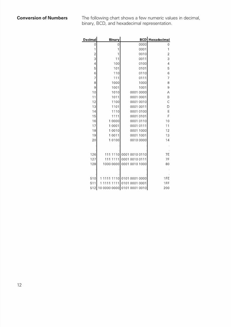
• Convert numbers from decimal to binary, BCD, andhexadecimal
• Identify typical discrete and analog inputs and outputs
• Read a basic ladder logic diagram and statement list
• Identify operational differences between different S7-200models
• Identify the proper manual to refer to for programming orinstallation of an S7-200 PLC
• Connect a simple discrete input and output to an S7-200
• Select the proper expansion module for analog inputs andoutputs
This knowledge will help you better understand customerapplications. In addition, you will be better able to describeproducts to customers and determine important differencesbetween products. You should complete Basics of Electricity
before attempting Basics of PLCs. An understanding of manyof the concepts covered in Basics of Electricity is required
for Basics of PLCs. In addition you may wish to complete
Basics of Control Components. Devices covered in Basicsof Control Components are used with programmable logiccontrollers.
If you are an employee of a Siemens Energy & Automationauthorized distributor, fill out the final exam tear-out card andmail in the card. We will mail you a certificate of completion if
you score a passing grade. Good luck with your efforts.
SIMATIC, STEP 7, STEP 7-Micro, STEP 7-Micro/WIN, PG 702,and PG 740 are registered trademarks of Siemens Energy &
Automation, Inc.
Other trademarks are the property of their respective owners.
Programmable Logic Controllers (PLCs), also referred to asprogrammable controllers, are in the computer family. They areused in commercial and industrial applications. A PLC monitors
inputs, makes decisions based on its program, and controlsoutputs to automate a process or machine. This course is meantto supply you with basic information on the functions andconfigurations of PLCs.
Siemens PLCs Siemens makes several PLC product lines in the SIMATIC® S7family. They are: S7-200, S7-300, and S7-400.
S7-200 The S7-200 is referred to as a micro PLC because of its smallsize. The S7-200 has a brick design which means that the
power supply and I/O are on-board. The S7-200 can be used on
smaller, stand-alone applications such as elevators, car washes,or mixing machines. It can also be used on more complexindustrial applications such as bottling and packaging machines.
S7-300 and S7-400 The S7-300 and S7-400 PLCs are used in more complexapplications that support a greater number of I/O points. BothPLCs are modular and expandable. The power supply and I/Oconsist of separate modules connected to the CPU. Choosingeither the S7-300 or S7-400 depends on the complexity of
the task and possible future expansion. Your Siemens salesrepresentative can provide you with additional information onany of the Siemens PLCs.
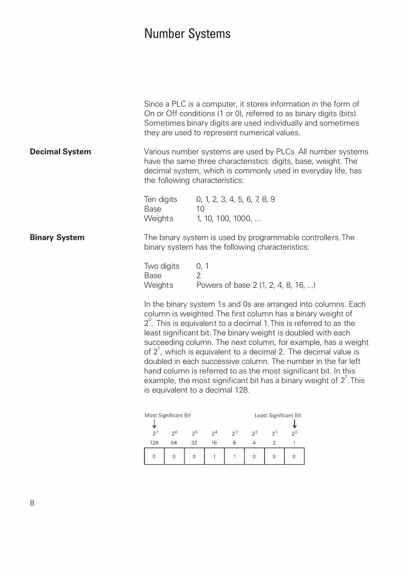
Since a PLC is a computer, it stores information in the form ofOn or Off conditions (1 or 0), referred to as binary digits (bits).Sometimes binary digits are used individually and sometimes
they are used to represent numerical values.
Decimal System Various number systems are used by PLCs. All number systemshave the same three characteristics: digits, base, weight. Thedecimal system, which is commonly used in everyday life, hasthe following characteristics:
Converting Binary The following steps can be used to interpret a decimalto Decimal number from a binary value.
1) Search from least to most significant bit for 1s.2) Write down the decimal representation of each column
containing a 1.
3) Add the column values.
In the following example, the fourth and fifth columns from theright contain a 1. The decimal value of the fourth column fromthe right is 8, and the decimal value of the fifth column fromthe right is 16. The decimal equivalent of this binary number is24. The sum of all the weighted columns that contain a 1 is thedecimal number that the PLC has stored.
In the following example the fourth and sixth columns from theright contain a 1. The decimal value of the fourth column fromthe right is 8, and the decimal value of the sixth column fromthe right is 32. The decimal equivalent of this binary number is
40.
Bits, Bytes, and Words Each binary piece of data is a bit. Eight bits make up one byte.Two bytes, or 16 bits, make up one word.
Logic 0, Logic 1 Programmable controllers can only understand a signal thatis On or Off (present or not present). The binary system is asystem in which there are only two numbers, 1 and 0. Binary 1indicates that a signal is present, or the switch is On. Binary 0indicates that the signal is not present, or the switch is Off.
BCD Binary-Coded Decimal (BCD) are decimal numbers whereeach digit is represented by a four-bit binary number. BCD iscommonly used with input and output devices. A thumbwheelswitch is one example of an input device that uses BCD. Thebinary numbers are broken into groups of four bits, each grouprepresenting a decimal equivalent. A four-digit thumbwheelswitch, like the one shown here, would control 16 (4 x 4) PLC
Hexadecimal Hexadecimal is another system used in PLCs. The hexadecimalsystem has the following characteristics:
16 digits 0, 1, 2, 3, 4, 5, 6, 7, 8, 9, A, B, C, D, E, FBase 16Weights Powers of base 16 (1, 16, 256, 4096 ...)
The ten digits of the decimal system are used for the first tendigits of the hexadecimal system. The first six letters of thealphabet are used for the remaining six digits.
A = 10 D = 13B = 11 E = 14C = 12 F = 15
The hexadecimal system is used in PLCs because it allows thestatus of a large number of binary bits to be represented in asmall space such as on a computer screen or programming
device display. Each hexadecimal digit represents the exactstatus of four binary bits. To convert a decimal number to ahexadecimal number the decimal number is divided by the baseof 16. To convert decimal 28, for example, to hexadecimal:
Decimal 28 divided by 16 is 1 with a remainder of 12. Twelve isequivalent to C in hexadecimal. The hexadecimal equivalent ofdecimal 28 is 1C.
The decimal value of a hexadecimal number is obtained bymultiplying the individual hexadecimal digits by the base 16weight and then adding the results. In the following examplethe hexadecimal number 2B is converted to its decimalequivalent of 43.
The language of PLCs consists of a commonly used setof terms; many of which are unique to PLCs. In order tounderstand the ideas and concepts of PLCs, an understanding
of these terms is necessary.
Sensor A sensor is a device that converts a physical condition into anelectrical signal for use by the PLC. Sensors are connected tothe input of a PLC. A pushbutton is one example of a sensorthat is connected to the PLC input. An electrical signal is sentfrom the pushbutton to the PLC indicating the condition (open/
closed) of the pushbutton contacts.
Actuators Actuators convert an electrical signal from the PLC into a
physical condition. Actuators are connected to the PLC output.A motor starter is one example of an actuator that is connectedto the PLC output. Depending on the output PLC signal themotor starter will either start or stop the motor.
Analog Inputs An analog input is a continuous, variable signal. Typical analoginputs may vary from 0 to 20 milliamps, 4 to 20 milliamps,or 0 to 10 volts. In the following example, a level transmittermonitors the level of liquid in a tank. Depending on the leveltransmitter, the signal to the PLC can either increase or
decrease as the level increases or decreases.
Discrete Outputs A discrete output is an output that is either in an ON or OFFcondition. Solenoids, contactor coils, and lamps are examplesof actuator devices connected to discrete outputs. Discreteoutputs may also be referred to as digital outputs. In thefollowing example, a lamp can be turned on or off by the PLCoutput it is connected to.
Programming A program consists of one or more instructions that accomplisha task. Programming a PLC is simply constructing a set ofinstructions. There are several ways to look at a program suchas ladder logic, statement lists, or function block diagrams.
Ladder Logic Ladder logic (LAD) is one programming language used with
PLCs. Ladder logic uses components that resemble elements
used in a line diagram format to describe hard-wired control.Refer to the STEP course Basics of Control Components formore information on line diagrams.
STEP 2000
Basics ofControlComponents
Ladder Logic Diagram The left vertical line of a ladder logic diagram represents thepower or energized conductor. The output element or instructionrepresents the neutral or return path of the circuit. The right
vertical line, which represents the return path on a hard-wiredcontrol line diagram, is omitted. Ladder logic diagrams are read
from left-to-right, top-to-bottom. Rungs are sometimes referredto as networks. A network may have several control elements,but only one output coil.
In the example program shown example I0.0, I0.1 and Q0.0represent the first instruction combination. If inputs I0.0 andI0.1 are energized, output relay Q0.0 energizes. The inputs couldbe switches, pushbuttons, or contact closures. I0.4, I0.5, andQ1.1 represent the second instruction combination. If eitherinput I0.4 or I0.5 are energized, output relay Q0.1 energizes.
Statement list A statement list (STL) provides another view of a set ofinstructions. The operation, what is to be done, is shown on theleft. The operand, the item to be operated on by the operation,is shown on the right. A comparison between the statementlist shown below, and the ladder logic shown on the previouspage, reveals a similar structure. The set of instructions in thisstatement list perform the same task as the ladder diagram.
Function Block Diagrams Function Block Diagrams (FBD) provide another view of a set of
instructions. Each function has a name to designate its specifictask. Functions are indicated by a rectangle. Inputs are shown
on the left-hand side of the rectangle and outputs are shown onthe right-hand side. The function block diagram shown belowperforms the same function as shown by the ladder diagramand statement list.
Memory Size Kilo, abbreviated K, normally refers to 1000 units. When talkingabout computer or PLC memory, however, 1K means 1024. Thisis because of the binary number system (2
10=1024). This can be
1024 bits, 1024 bytes, or 1024 words, depending on memorytype.
RAM Random Access Memory (RAM) is memory where data can bedirectly accessed at any address. Data can be written to and
read from RAM. RAM is used as a temporary storage area.RAM is volatile, meaning that the data stored in RAM will belost if power is lost. A battery backup is required to avoid losing
data in the event of a power loss.
ROM Read Only Memory (ROM) is a type of memory that data canbe read from but not written to. This type of memory is usedto protect data or programs from accidental erasure. ROMmemory is nonvolatile. This means a user program will not losedata during a loss of electrical power. ROM is normally used to
store the programs that define the capabilities of the PLC.
EPROM Erasable Programmable Read Only Memory (EPROM) providessome level of security against unauthorized or unwantedchanges in a program. EPROMs are designed so that datastored in them can be read, but not easily altered. ChangingEPROM data requires a special effort. UVEPROMs (ultravioleterasable programmable read only memory) can only be erasedwith an ultraviolet light. EEPROM (electronically erasableprogrammable read only memory), can only be erased
electronically.
Firmware Firmware is user or application specific software burned intoEPROM and delivered as part of the hardware. Firmware givesthe PLC its basic functionality.
Putting it Together The memory of the S7-200 is divided into three areas: programspace, data space, and configurable parameter space.
• Program space stores the ladder logic (LAD) or statementlist (STL) program instructions. This area of memory controlsthe way data space and I/O points are used. LAD or STLinstructions are written using a programming device such as
a PC, then loaded into program memory of the PLC.
• Data space is used as a working area, and includes memory
locations for calculations, temporary storage of intermediateresults and constants. Data space includes memorylocations for devices such as timers, counters, high-speedcounters, and analog inputs and outputs. Data space can beaccessed under program control.
• Configurable parameter space, or memory, stores either the
Programming Devices The program is created in a programming device (PG) and thentransferred to the PLC. The program for the S7-200 can becreated using a dedicated Siemens SIMATIC S7 programmingdevice, such as a PG 720 (not shown) or PG 740, if STEP 7Micro/WIN software is installed.
A personal computer (PC), with STEP 7 Micro/WIN installed,can also be used as a programming device with the S7-200.
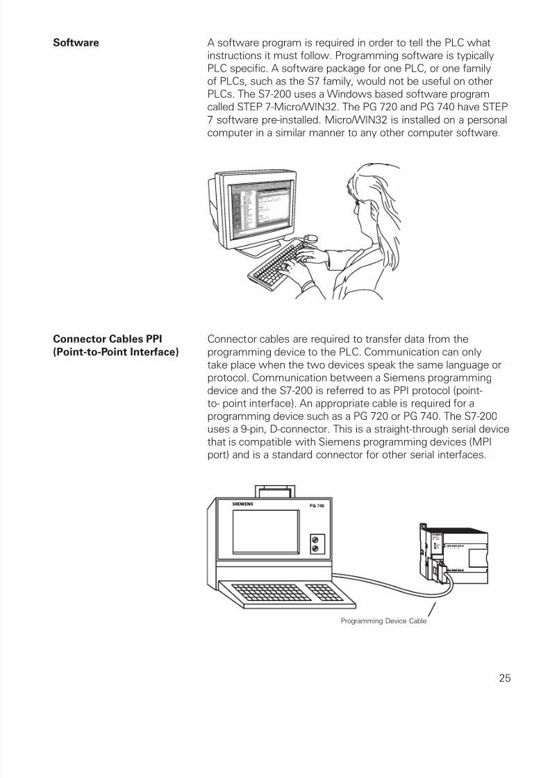
Software A software program is required in order to tell the PLC whatinstructions it must follow. Programming software is typicallyPLC specific. A software package for one PLC, or one familyof PLCs, such as the S7 family, would not be useful on otherPLCs. The S7-200 uses a Windows based software programcalled STEP 7-Micro/WIN32. The PG 720 and PG 740 have STEP
7 software pre-installed. Micro/WIN32 is installed on a personal
computer in a similar manner to any other computer software.
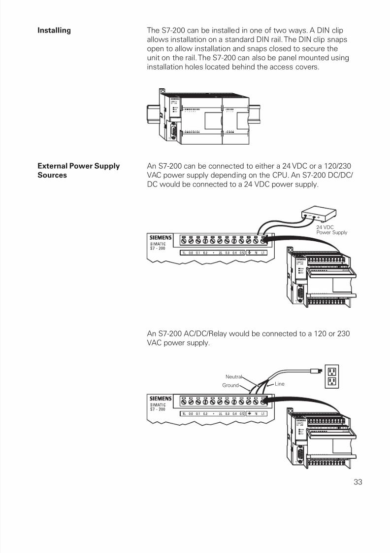
Connector Cables PPI Connector cables are required to transfer data from the(Point-to-Point Interface) programming device to the PLC. Communication can only
take place when the two devices speak the same language orprotocol. Communication between a Siemens programmingdevice and the S7-200 is referred to as PPI protocol (point-
to- point interface). An appropriate cable is required for aprogramming device such as a PG 720 or PG 740. The S7-200uses a 9-pin, D-connector. This is a straight-through serial devicethat is compatible with Siemens programming devices (MPIport) and is a standard connector for other serial interfaces.
A special cable is needed when a personal computer is used asa programming device. Two versions of this cable are available.One version, called an RS-232/PPI Multi-Master Cable, connectsa personal computer’s RS-232 interface to the PLC’s RS-485connector. The other version, called a USB/PPI Multi-Master
Cable, connects a personal computer’s USB interface to thePLC’s RS-485 connector.
The S7-200 Micro PLC is the smallest member of the SIMATICS7 family of programmable controllers. The central processingunit (CPU) is internal to the PLC. Inputs and outputs (I/O) are
the system control points. Inputs monitor field devices, such asswitches and sensors. Outputs control other devices, such asmotors and pumps. The programming port is the connection tothe programming device.
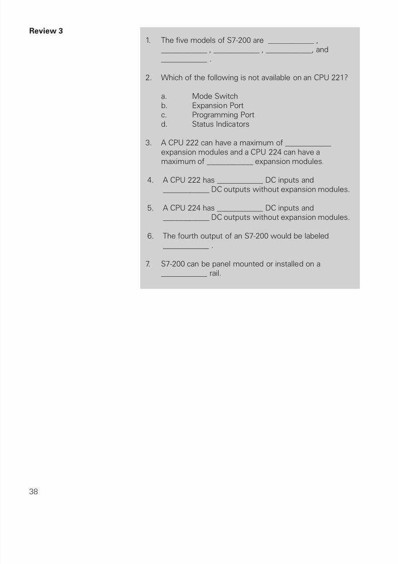
S7-200 Models There are five S7-200 CPU types: CPU 221, CPU 222, CPU 224,
CPU 224XP, and CPU 226 and two power supply configurationsfor each type.
Model Description Power Supply Input Types Output Types
221 DC/DC/DC 20.4-28.8 VDC 6 DC 4 DC
221 AC/DC/Relay 85-264 VAC, 47-63 Hz 6 DC 4 Relay
222 DC/DC/DC 20.4-28.8 VDC 8 DC 6 DC
222 AC/DC/Relay 85-264 VAC, 47-63 Hz 8 DC 6 Relay
224 DC/DC/DC 20.4-28.8 VDC 14 DC 10 DC
224 AC/DC/Relay 85-264 VAC, 47-63 Hz 14 DC 10 Relay
224XP DC/DC/DC 20.4-28.8 VDC 14 DC, 2 Analog 10 DC, 1 Analog
224XP AC/DC/Relay 85-264 VAC, 47-63 Hz 14 DC, 2 Analog 10 Relay, 1 Analog
226 DC/DC/DC 20.4-28.8 VDC 24 DC 16 DC
226 AC/DC/Relay 85-264 VAC, 47-63 Hz 24 DC 16 Relay
The model description indicates the type of CPU, the powersupply, the type of input, and the type of output.
Mode Switch and When the mode switch is in the RUN position the CPU is in theAnalog Adjustment run mode and executing the program. When the mode switch
is in the STOP position the CPU is stopped. When the modeswitch is in the TERM position the programming device canselect the operating mode.
The analog adjustment is used to increase or decrease values
stored in special memory. These values can be used to updatethe value of a timer or counter, or can be used to set limits.
Optional Cartridge The S7-200 supports an optional memory cartridge that
provides a portable EEPROM storage for your program. Thecartridge can be used to copy a program from one S7-200 PLCto a like S7-200 PLC.
In addition, two other cartridges are available. A real-time clockwith battery is available for use on the CPU 221 and CPU 222.
The battery provides up to 200 days of data retention timein the event of a power loss. The CPU 224, CPU 224XP andCPU 226 have a real-time clock built in. Another cartridge is
Expansion Modules The S7-200 PLCs are expandable. Expansion modules containadditional inputs and outputs. These are connected to the baseunit using a ribbon connector.
The ribbon connector is protected by a cover on the base unit.Side-by-side mounting completely encloses and protects theribbon connector.
Available Expansion The CPU 221 comes with 6 digital inputs and 4 digital outputs.These are not expandable. The CPU 222 comes with 8 digitalinputs and 6 digital outputs and will accept up to 2 expansionmodules. The CPU 224 and CPU 224XP come with 14 digital
inputs and 10 digital outputs and will accept up to 7 expansionmodules. The S7-226 comes with 24 digital inputs and 16
digital outputs and will accept up to 7 expansion modules.
6 Inputs, 4 Outputs
No Expansion Modules (EM)
8 Inputs, 6 Outputs
Up to 2 Expansion Modules
14 Inputs, 10 Outputs
Up to 7 Expansion Module
14 Inputs, 10 Outputs
2 Analog In, 1 Analog Out
Up to 7 Expansion Module
24 Inputs, 16 Outputs
Up to 7 Expansion Module
CPU221
CPU222
CPU224
CPU224XP
EM EM
CPU226
EM EM
EM EM
EM EM
EM
EM EM EM EM EM EM EM
EM EM
EMEM EM EM EM
Status Indicators The CPU status indicators reflect the current mode of CPU
operation. When the CPU is in the RUN mode, the green RUNindicator is lit. When the CPU is in the STOP mode, the yellow
STOP indicator is lit. The System Fault/Diagnostic (SF/DIAG)indicator turns red for a system fault and yellow to indicatecertain diagnostic conditions.
The I/O status indicators represent the On or Off status ofcorresponding inputs and outputs. For example, when the CPUsenses an input is on, the corresponding green indicator is lit.
Installing The S7-200 can be installed in one of two ways. A DIN clipallows installation on a standard DIN rail. The DIN clip snapsopen to allow installation and snaps closed to secure theunit on the rail. The S7-200 can also be panel mounted usinginstallation holes located behind the access covers.
External Power Supply An S7-200 can be connected to either a 24 VDC or a 120/230Sources VAC power supply depending on the CPU. An S7-200 DC/DC/
DC would be connected to a 24 VDC power supply.
24 VDCPower Supply
An S7-200 AC/DC/Relay would be connected to a 120 or 230VAC power supply.
Input Simulator A convenient method of testing a program is to wire toggleswitches to the inputs. Input simulators with prewired toggleswitches are available for the S7-200s. Switches are wiredbetween the 24 VDC power supply (L+) and the inputs. Forexample, the switch on the far left is wired between the firstinput (0.0) and L+. When the switch is closed, 24 VDC is applied
to the input. This is referred to as a logic 1. When the switch
is open, 0 VDC is applied to the input. This is referred to as alogic 0.
Outputs Output devices, such as relays, are connected to the terminalstrip under the top cover of the PLC. When testing a program,it is not necessary to connect output devices. The LED statusindicators signal if an output is active.
Optional Connector An optional fan-out connector allows for field wiring connectionsto remain fixed when removing or replacing a CPU 221 orCPU 222. The appropriate connector slides into either the input,output, or expansion module terminals.
Removable Terminal Strip The CPU 224, CPU 224XP, and CPU 226 do not have an optionalfan-out connector. Instead, the terminal strips are removable.This allows the field wiring connections to remain fixed whenremoving or replacing the PLC.
Super Capacitor A super capacitor, so named because of its ability to maintain acharge for a long period of time, protects data stored in RAM inthe event of a power loss. The RAM memory is typically backedup on the CPU 221 and CPU 222 for 50 hours, and on theCPU 224, CPU 224 XP, and CPU 226 for 100 hours.
Reference Manual The SIMATIC S7-200 Programmable Controller System
Manual provides complete information on installing andprogramming the S7-200 PLCs.
TD200 The S7-200 programming port can be used to communicatewith a variety of external devices. One such device is the TD200text display unit. The TD200 displays messages read from theS7-200, allows adjustment of designated program variables,
provides the ability to force, and permits setting of the time anddate. The TD200 can be connected to an external power supplyor receive its power from the S7-200.
ProgrammingDevice Cable
PPI Protocol
SF/DIAG
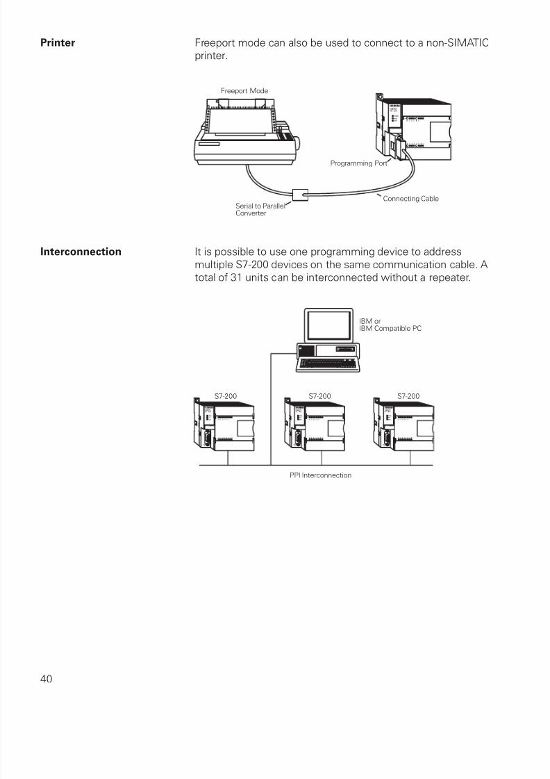
Freeport Mode The programming port has a mode called freeport mode.Freeport mode allows connectivity to various intelligent sensingdevices such as a bar code reader.
STEP 7-Micro/WIN32 is the program software used with theS7-200 PLC to create the PLC operating program. STEP 7consists of a number of instructions that must be arrangedin a logical order to obtain the desired PLC operation. These
instructions are divided into three groups: standard instructions,special instructions, and high-speed instructions.
Standard Instructions Standard instructions consists of instructions that are found inmost programs. Standard instructions include: timer, counter,math, logical, increment/decrement/invert, move, and block
instructions.
Special Instructions Special instructions are used to manipulate data. Specialinstructions include: shift, table, find, conversion, for/next, andreal-time instructions.
High-Speed Instructions High-speed instructions allow for events and interrupts to occurindependent of the PLC scan time. These include high-speedcounters, interrupts, output, and transmit instructions.
It is not the purpose of this text to explain all of the instructions
and capabilities. A few of the more common instructionsnecessary for a basic understanding of PLC operation willbe discussed. PLC operation is limited only by the hardware
capabilities and the ingenuity of the person programming it.Refer to the SIMATIC S7-200 Programmable Controller
System Manual for detailed information concerning theseinstructions.
Micro/WIN32 The programming software can be run Off-line or On-line. Off-line programming allows the user to edit the ladder diagramand perform a number of maintenance tasks. The PLC doesnot need to be connected to the programming device in thismode. On-line programming requires the PLC to be connected
to the programming device. In this mode program changes aredownloaded to the PLC. In addition, status of the input/output
elements can be monitored. The CPU can be started, stopped,or reset.
Symbols In order to understand the instructions a PLC is to carry out, an
understanding of the language is necessary. The language ofPLC ladder logic consists of a commonly used set of symbolsthat represent control components and instructions.
Contacts One of the most confusing aspects of PLC programming forfirst-time users is the relationship between the device thatcontrols a status bit and the programming function that usesa status bit. Two of the most common programming functionsare the normally open (NO) contact and the normally closed(NC) contact. Symbolically, power flows through these contactswhen they are closed. The normally open contact (NO) is closed
when the input or output status bit controlling the contact is 1.The normally closed contact (NC) is closed when the input or
Coils Coils represent relays that are energized when power flowsto them. When a coil is energized, it causes a correspondingoutput to turn on by changing the state of the status bitcontrolling that output to 1. That same output status bit may beused to control normally open and normally closed contactselsewhere in the program.
Boxes Boxes represent various instructions or functions that areexecuted when power flows to the box. Typical box functionsare timers, counters, and math operations.
Entering Elements Control elements are entered in the ladder diagram bypositioning the cursor and selecting the element from a lists.In the following example the cursor has been placed in theposition to the right of I0.2. A coil was selected from a pull-
An AND Operation Each rung or network on a ladder represents a logic operation.The following programming example demonstrates an ANDoperation. Two contact closures and one output coil are placedon network 1. They were assigned addresses I0.0, I0.1, andQ0.0. Note that in the statement list a new logic operation
always begins with a load instruction (LD). In this example I0.0(input 1) and (A in the statement list) I0.1 (input 2) must be
true in order for output Q0.0 (output 1) to be true. It can alsobe seen that I0.0 and I0.1 must be true for Q0.0 to be true bylooking at the function block diagram representation.
Another way to see how an AND function works is witha Boolean logic diagram. In Boolean logic an AND gate isrepresented by a number of inputs on the left side. In this case
there are two inputs. The output is represented on the rightside. It can be seen from the table that both inputs must be alogic 1 in order for the output to be a logic 1.
Testing a Program Once a program has been written it needs to be tested anddebugged. One way this can be done is to simulate the fieldinputs with an input simulator, such as the one made for theS7-200. The program is first downloaded from the programmingdevice to the CPU. The selector switch is placed in the RUN
position. The simulator switches are operated and the resultingindication is observed on the output status indicator lamps.
Status Functions After a program has been loaded and is running in the PLC, theactual status of ladder elements can be monitored using STEP7 Micro/WIN32 software. The standard method of showing aladder element is by indicating the circuit condition it produceswhen the device is in the deenergized or non operated state.
In the following illustration input 1 (I0.0) is programmed as a
normally open (NO) contact. In this condition, power will notflow through the contacts to the output (Q0.0).
When viewing the ladder diagram in the status mode, controlelements that are active, or true (logic 1), are highlighted. In theexample shown the toggle switch connected to input 1 hasbeen closed. Power can now flow through the control elementassociated with input 1 (I0.0) and activate the output (Q0.0). Thelamp will illuminate.
Forcing Forcing is another useful tool in the commissioning of anapplication. It can be used to temporarily override the inputor output status of the application in order to test and debugthe program. The force function can also be used to overridediscrete output points. The force function can be used to skipportions of a program by enabling a jump instruction with aforced memory bit. Under normal circumstances the toggleswitch, shown in the illustration below, would have to be closed
to enable input 1 (I0.0) and turn on the output light. Forcingenables input 1 even though the input toggle switch is open.With input 1 forced high the output light will illuminate. Whena function is forced the control bit identifier is highlighted. The
To understand discrete control of a programmable controller thesame simple lamp circuit illustrated with forcing will be used.This is only for instructional purposes as a circuit this simplewould not require a programmable controller. In this example
the lamp is off when the switch is open and on when theswitch is closed.
Wiring To accomplish this task, a switch is wired to the input of the
PLC and an indicator light is wired to output terminal.
The following drawing illustrates the sequence of events. Aswitch is wired to the input module of the PLC. A lamp is wiredto the output module. The program is in the CPU. The CPUscans the inputs. When it finds the switch open I0.0 receivesa binary 0. This instructs Q0.0 to send a binary 0 to the output
module. The lamp is off. When it finds the switch closed I0.0receives a binary 1. This instructs Q0.0 to send a binary 1 to the
output module, turning on the lamp.
Program Instruction When the switch is open the CPU receives a logic 0 from inputI0.0. The CPU sends a logic 0 to output Q0.0 and the light is off.
When the switch is closed the CPU receives a logic 1 frominput I0.0. The CPU sends a logic 1 to output Q0.0, thusactivating Q0.0. The light turns on.
Motor Starter Example The following example involves a motor start and stop circuit.The line diagram illustrates how a normally open and anormally closed pushbutton might be used in a control circuit.In this example a motor started (M) is wired in series witha normally open momentary pushbutton (Start), a normallyclosed momentary pushbutton (Stop), and the normally closed
contacts of an overload relay (OL).
Momentarily depressing the Start pushbutton completes thepath of current flow and energizes the motor starter (M).
This closes the associated M and Ma (auxiliary contact locatedin the motor starter) contacts. When the Start button is releaseda holding circuit exists to the M contactor through the auxiliarycontacts Ma. The motor will run until the normally closedStop button is depressed, or the overload relay opens the OL
contacts, breaking the path of current flow to the motor starterand opening the associated M and Ma contacts.
This control task can also be accomplished with a PLC.
Program Instruction A normally open Start pushbutton is wired to the first input(I0.0), a normally closed Stop pushbutton is wired to the secondinput (I0.1), and normally closed overload relay contacts (partof the motor starter) are connected to the third input (I0.2).The first input (I0.0), second input (I0.1), and third input (I0.2)form an AND circuit and are used to control normally open
programming function contacts on Network 1. I0.1 status bit is
a logic 1 because the normally closed (NC) Stop Pushbutton isclosed. I0.2 status bit is a logic 1 because the normally closed(NC) overload relay (OL) contacts are closed. Output Q0.0 isalso programmed on Network 1. In addition, a normally open setof contacts associated with Q0.0 is programmed on Network1 to form an OR circuit. A motor starter is connected to outputQ0.0.
When the Start pushbutton is depressed the CPU receives alogic 1 from input I0.0. This causes the I0.0 contact to close.All three inputs are now a logic 1. The CPU sends a logic 1to output Q0.0. The motor starter is energized and the motorstarts.
When the Start pushbutton is pressed, output Q0.0 is nowtrue and on the next scan, when normally open contact Q0.0 issolved, the contact will close and output Q0.0 will stay on evenif the Start pushbutton has been released.
The motor will continue to run until the Stop pushbutton isdepressed. Input I0.1 will now be a logic 0 (false). The CPU willsend a binary 0 to output Q0.0. The motor will turn off.
It can be seen from the ladder logic that a normally open outputQ0.0 is connected on Network 2 to output Q0.1 and a normallyclosed Q0.0 contact is connected to output Q0.2 on network3. In a stopped condition output Q0.0 is off. The normally openQ0.0 contacts on Network 2 are open and the RUN indicator,
connected to output Q0.1 light is off. The normally closed Q0.1on Network 3 lights are closed and the STOP indicator light,
When the PLC starts the motor output Q0.0 is now a logichigh (On). The normally open Q0.0 contacts on Network 2 nowswitch to a logic 1 (closed) and output Q0.1 turns the RUNindicator on. The normally closed Q0.0 contacts on Network3 switch to a logic 0 (open) and the STOP indicator lightconnected to output Q0.2 is now off.
Adding a Limit Switch The application can be further expanded by adding a limitswitch with normally open contacts to input I0.3.
A limit switch could be used to stop the motor or prevent themotor from being started. An access door to the motor, or itsassociated equipment, is one example of a limit switch’s use.If the access door is open, the normally open contacts of LS1connected to input I0.3 are open and the motor will not start.
When the access door is closed, the normally open contacts onthe limit switch (LS1) are closed. Input I0.3 is now on (logic 1),and the motor will start when the Start pushbutton is pressed.
Expansion The PLC program can be expanded to accommodate manycommercial and industrial applications. Additional Start/Stoppushbuttons and indicator lights can be added for remoteoperation, or control of a second motor starter and motor.Overtravel limit switches can be added along with proximityswitches for sensing object position. In addition, expansion
modules can be added to further increase the I/O capability. The
applications are only limited by the number of I/Os and amountof memory available on the PLC.
PLCs must also work with continuous or analog signals. Typicalanalog signals are 0 - 10 VDC or 4 - 20 mA. Analog signals areused to represent changing values such as speed, temperature,weight, and level. A PLC cannot process these signals in
an analog form. The PLC must convert the analog signalinto a digital representation. An expansion module, capableof converting the analog signal, must be used. The S7-200analog modules convert standard voltage and current analogvalues into a 12-bit digital representation. The digital values aretransferred to the PLC for use in register or word locations.
In addition, analog modules are available for use with
thermocouple and RTD type sensors used in to achieve a highlevel of accuracy in temperature measurement.
Application Example A field device that measures a varying value is typicallyconnected to a transducer. In the following example a scaleis connected to a load cell. A load cell is a device that takes avarying value and converts it to a variable voltage or currentoutput. In this example the load cell is converting a value of
weight into a 0 - 10 VDC output. The output value dependsentirely on the manufactured specifications for the device. This
load cell outputs 0 - 10 VDC for a 0 - 500 Lbs input. The 0 - 10VDC load cell output is connected to the input of an analogexpansion module.
The example application can be expanded to include a conveyor
system with a gate to direct packages of varying weight.As packages move along the conveyor they are weighed. Apackage that weighs at or greater than a specified value isrouted along one conveyor path. A package that weighs less
than a specified value is routed along another conveyor path,where it will later be inspected for missing contents.
Analog Outputs Analog outputs are used in applications requiring controlcapability of field devices which respond to continuous voltageor current levels. Analog outputs may be used as a variablereference for control valves, chart recorders, electric motordrives, analog meters, and pressure transducers. Like analoginputs, analog outputs are generally connected to a controlling
device through a transducer. The transducer takes the voltage
signal and, depending on the requirement, amplifies, reduces,or changes it into another signal which controls the device. Inthe following example a 0 - 10 VDC signal controls a 0 - 500 Lbs.scale analog meter.
Timers are devices that count increments of time. Traffic lightsare one example where timers are used. In this example timersare used to control the length of time between signal changes.
Timers are represented by boxes in ladder logic. When a timerreceives an enable, the timer starts to time. The timer comparesits current time with the preset time. The output of the timeris a logic 0 as long as the current time is less than the presettime. When the current time is greater than the preset time the
timer output is a logic 1. S7-200 uses three types of timers: On-Delay (TON), Retentive On-Delay (TONR), and Off-Delay (TOF).
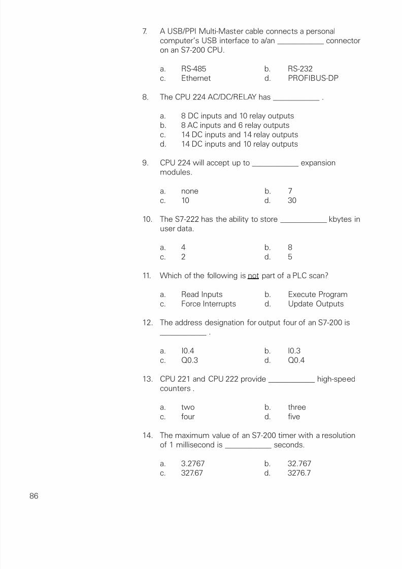
S7-200 Timers S7-200 timers are provided with resolutions of 1 millisecond,10 milliseconds, and 100 milliseconds. The maximum value ofthese timers is 32.767 seconds, 327.67 seconds, and 3276.7seconds, respectively. By adding program elements, logic canbe programmed for much greater time intervals.
Hard-Wired Timing Circuit Timers used with PLCs can be compared to timing circuits used
in hard-wired control line diagrams. In the following example, anormally open (NO) switch (S1) is used with a timer (TR1). Forthis example the timer has been set for 5 seconds. When S1is closed, TR1 begins timing. When 5 seconds have elapsed,TR1 will close its associated normally open TR1 contacts,illuminating pilot light PL1. When S1 is open, deenergizing TR1,the TR1 contacts open, immediately extinguishing PL1. This type
of timer is referred to as ON delay. ON delay indicates that oncea timer receives an enable signal, a predetermined amount oftime (set by the timer) must pass before the timer’s contactschange state.
On-Delay (TON) When the On-Delay timer (TON) receives an enable (logic 1) atits input (IN), a predetermined amount of time (preset time - PT)passes before the timer bit (T-bit) turns on. The T-bit is a logicfunction internal to the timer and is not shown on the symbol.The timer resets to the starting time when the enabling inputgoes to a logic 0.
In the following simple timer example, a switch is connected toinput I0.3, and a light is connected to output Q0.1.
When the switch is closed input 4 becomes a logic 1, whichis loaded into timer T37. T37 has a time base of 100 ms (.100seconds). The preset time (PT) value has been set to 150. Thisis equivalent to 15 seconds (.100 x 150 ). The light will turn on15 seconds after the input switch is closed. If the switch wereopened before 15 seconds had passed, then reclosed, the timerwould again begin timing at 0.
A small sample of the flexibility of PLCs is shown in thefollowing program logic. By reprogramming the T37 contact asa normally closed contact, the function of the circuit is changedto cause the indicator light to turn off only when the timer timesout. This function change was accomplished without changingor rewiring I/O devices.
T37
150
I0.3
Q0.1
TON
T37
IN
PT
Retentive On-Delay (TONR) The Retentive On-Delay timer (TONR) functions in a similarmanner to the On-Delay timer (TON). There is one difference.
The Retentive On-Delay timer times as long as the enablinginput is on, but does not reset when the input goes off. Thetimer must be reset with a RESET (R) instruction.
The same example used with the On-Delay timer will beused with the Retentive On-Delay timer. When the switch isclosed at input I0.3, timer T5 (Retentive timer) begins timing.If, for example, after 10 seconds input I0.3 is opened the timerstops. When input I0.3 is closed the timer will begin timing at
10 seconds. The light will turn on 5 seconds after input I0.3has been closed the second time. A RESET (R) instruction
can be added. Here a pushbutton is connected to input I0.2.If after 10 seconds input I0.3 were opened, T5 can be reset bymomentarily closing input I0.2. T5 will be reset to 0 and begintiming from 0 when input I0.3 is closed again.
T5
T5
150
I0.3
I0.2
Q0.1
R
TONR
T5
IN
PT
Off-Delay (TOF) The Off-Delay timer is used to delay an output off for a fixedperiod of time after the input turns off. When the enabling bitturns on the timer bit turns on immediately and the value is setto 0. When the input turns off, the timer counts until the preset
S7-200 Timers The S7-200s have 256 timers. The specific T number chosenfor the timer determines its time base and whether it is TON,TONR, or TOF.
Timer Example In the following example a tank will be filled with twochemicals, mixed, and then drained. When the Start Button ispressed at input I0.0, the program starts pump 1 controlled byoutput Q0.0. Pump 1 runs for 5 seconds, filling the tank with
the first chemical, then shuts off. The program then starts pump2, controlled by output Q0.1. Pump 2 runs for 3 seconds fillingthe tank with the second chemical. After 3 seconds pump 2shuts off. The program starts the mixer motor, connected tooutput Q0.2 and mixes the two chemicals for 60 seconds. Theprogram then opens the drain valve controlled by output Q0.3,and starts pump 3 controlled by output Q0.4. Pump 3 shuts offafter 8 seconds and the process stops. A manual Stop switch is
Counters are represented by boxes in ladder logic. Countersincrement/decrement one count each time the input transitionsfrom off (logic 0) to on (logic 1). The counters are reset whena RESET instruction is executed. S7-200 uses three types ofcounters: up counter (CTU), down counter (CTD), and up/down
counter (CTUD).
Count Up/DownCount Up Count Down
PV PV
R LD
PV
CU CDCD
CU
R
CTU CTD CTUD
XXX XXX XXX
S7-200 Counters There are 256 counters in the S7-200, numbered C0 throughC255. The same number cannot be assigned to more thanone counter. For example, if an up counter is assigned number45, a down counter cannot also be assigned number 45. Themaximum count value of a counter is ±32,767.
Up Counter The up counter counts up from a current value to a preset value(PV). Input CU is the count input. Each time CU transitions froma logic 0 to a logic 1 the counter increments by a count of 1.Input R is the reset. A preset count value is stored in PV input.
If the current count is equal to or greater than the preset valuestored in PV, the output bit (Q) turns on (not shown).
Down Counter The down counter counts down from the preset value (PV) eachtime CD transitions from a logic 0 to a logic 1. When the currentvalue is equal to zero the counter output bit (Q) turns on (notshown). The counter resets and loads the current value with thepreset value (PV) when the load input (LD) is enabled.
PV
LD
CD
CTD
XXX
Up/Down Counter The up/down counter counts up or down from the preset valueeach time either CD or CU transitions from a logic 0 to a logic 1.
When the current value is equal to the preset value, the outputQU turns on. When the current value (CV) is equal to zero, theoutput QD turns on. The counter loads the current value (CV)with the preset value (PV) when the load input (LD) is enabled.
Similarly, the counter resets and loads the current value (CV)with zero when the reset (R) is enabled. The counter stopscounting when it reaches preset or zero.
Counter Example A counter might be used to keep track of the number ofvehicles in a parking lot. As vehicles enter the lot through anentrance gate, the counter counts up. As vehicles exit the lotthrough an exit gate, the counter counts down. When the lot isfull a sign at the entrance gate turns on indicating the lot is full.
Up/down counter C48 is used in this example. A switch,connected to the entrance gate, has been wired to input I0.0.
A switch, connected to the exit gate, has been wired to inputI0.1. A reset switch, located at the collection booth, has beenwired to input I0.2. The parking lot has 150 parking spaces. Thisvalue has been stored in the preset value (PV). The counteroutput has been directed to output Q0.1. Output 2 is connectedto a “Parking Lot Full” sign. As cars enter the lot the entrancegate opens. Input I0.0 transitions from a logic 0 to a logic 1,incrementing the count by one. As cars leave the lot the exitgate opens. Input I0.1 transitions from a logic 0 to a logic 1,
decrementing the count by 1. When the count has reached 150output Q0.1 transitions from a logic 0 to a logic 1. The “ParkingLot Full” sign illuminates. When a car exits, decrementing thecount to 149, the sign turns off.
As discussed earlier, PLCs have a scan time. The scan timedepends on the size of the program, the number of I/Os, andthe amount of communication required. Events may occur inan application that require a response from the PLC before
the scan cycle is complete. For these applications high-speedinstructions can be used.
High-Speed Counters High-speed counters are represented by boxes in ladder logic.CPU 221 and CPU 222 support four high-speed counters
(HSC0, HSC3, HSC4, HSC5). CPU 224, CPU 224XP, andCPU 226 support six high-speed counters (HSC0, HSC1, HSC2,HSC3, HSC4, HSC5).
Definition Boxes and The high-speed counter definition boxes are used to assignHigh-Speed Counters a mode to the counter. High-speed counters can be defined
by the definition box to operate in any of the twelve availablemodes. It should be noted that not all counters can operatein all of the available modes. Refer to the S7-Programmable
Controller System Manual for definitions available for eachcounter. Each counter has dedicated inputs for clocks, direction
control, reset, and start where these functions are supported.
Positioning Positioning is one example of an application that can usehigh-speed counters. In the following illustration a motor isconnected through a starter to a PLC output. The motor shaftis connected to an encoder and a positioning actuator. The
encoder emits a series of pulses as the motor turns. In thisexample the program will move an object from position 1 toposition 6. Assume the encoder generates 600 pulses perrevolution, and it takes 1000 motor revolutions to move theobject from one position to another. To move the object from
position 1 to position 6 (5 positions) would take 5000 motorrevolutions. The counter would count up 30,000 counts (5000revolutions x 600 pulses per revolution) and stop the motor.
1 2 3 4 5 6 7 8 9 100
MotorEncoder
Starter
Interrupts Interrupts are another example of an instruction that mustbe executed before the PLC has completed the scan cycle.Interrupts in the S7-200 are prioritized in the following order:
In addition to I/O modules, expansion modules are availablefor the S7-200 that measure temperature, control positioningapplications, and provide various communication functions.
EM 241 In any complex system communication is essential. Modemsare electronic devices used for sending and receiving dataover long distances. The EM 241 is an expansion module thatsupports communication between an S7-200 PLC and STEP 7Micro/WIN via a modem.
The EM 241 provides an international telephone line interface,
supports sending numeric and text paging messages, as wellas SMS (Short Message Service) messages to cellular phones.This is useful for remote diagnostics and maintenance, machinecontrol, alarm systems, and general communication functions.
In addition to CPU-to-CPU communication via a telephone line,the EM 241 also supports the ModBus RTU protocol. Protocolsare rules that identify how devices should communicate witheach other. ModBus RTU is a protocol originally developedby MODICON, which is now part of Schneider Automation.ModBus RTU has been widely used by other companies.
CP 243-1, CP 243-1 IT Industrial Ethernet provides a proven means of networkingcomputers and a variety of intelligent devices. CP 243-1 and
CP 243-1 IT are communication processors used to connect theS7-200 system to Industrial Ethernet.
The S7-200 can be remotely configured, programmed, anddiagnosed via Industrial Ethernet using STEP 7 Micro/WIN.The S7-200 can also communicate with other S7-200, S7-300,and S7-400 PLCs and a variety of other devices using IndustrialEthernet.
The IT functions of the CP 243-1 IT Internet module simplify theprocess of setting up a control system that can email diagnosticinformation or transfer files using Internet protocols.
EM 277 Information flow between intelligent devices such as PLCs,computers, variable speed drives, actuators, and sensors isoften accomplished through a local area network (LAN). LANsare used in office, manufacturing, and industrial areas.
In the past, these networks were often proprietary systemsdesigned to a specific vendor’s standards. Siemens hasbeen a leader in pushing the trend to open systems basedupon international standards developed through industryassociations. PROFIBUS-DP and Actuator Sensor Interface (AS-i) are examples of these open networks.
The PROFIBUS-DP EM 277 module allows connection ofthe S7-200 CPU to a PROFIBUS-DP network as a slave. TheCP 243-2 Communication Processor allows communicationbetween AS-i devices and an S7-200.
PLCs, for example, use I/O modules to receive inputs frombinary devices such as sensors. Binary outputs are used to turnon or off a process as the result of an input.
EM 253 Position control describes a range of applications that involvemovement with varying degrees of precision. Rotary tables andtraversing cars are examples where objects are moved fromone position during a product’s manufacturing process.
The EM 253 is a positioning module that enables the user tocontrol the speed and position for either stepper motors orservo motors. The EM 253 interfaces between an S7-200 PLC
and the stepper/servo motor’s power control module.
The final exam is intended to be a learning tool. The bookmay be used during the exam. A tear-out answer sheet isprovided. After completing the test, mail the answer sheet in forgrading. A grade of 70% or better is passing. Upon successful
completion of the test a certificate will be issued.
1. The component of a PLC that makes decisions andexecutes control instructions based on the input signals isthe ____________ .
a. CPU b. Input module c. Programming device d. Operator interface
2. One byte is made up of ____________ .
a. 2 bits b. 8 bits c. 16 bits d. 32 bits
3. The binary equivalent of a decimal 5 is ____________ .
a. 11 b. 100
c. 101 d. 111
4. An input that is either On or Off is a/an ____________ input.
a. analog b. discrete c. high-speed d. normally open
5. A programming language that uses symbols resembling
elements used in hard-wired control line diagrams isreferred to as a ____________ .
a. ladder logic diagram b. statement list c. network d. PLC scan
6. A type of memory that can be read from but not written tois ____________ .
quickSTEP online courses are available athttp://www.sea.siemens.com/step.
The quickSTEP training site is divided into three sections:
Courses, Downloads, and a Glossary. Online coursesinclude reviews, a final exam, the ability to print a certificateof completion, and the opportunity to register in the Sales& Distributor training database to maintain a record of youraccomplishments.
From this site the complete text of all STEP courses can bedownloaded in PDF format. These files contain the most recentchanges and updates to the STEP courses.
A unique feature of the quickSTEP site is our pictorial glossary.
The pictorial glossary can be accessed from anywhere withina quickSTEP course. This enables the student to look up anunfamiliar word without leaving the current work area.