12
OPERATOR’S MANUAL COVERS HOLE PUNCHER PART NUMBERS 0756102 & 0756202 75006PR PUNCH PRO ™ ELECTRO-HYDRAULIC HOLE PUNCHER OM75006PR1114 Printed in U.S.A.

operator’s manualCOVERS HOLE PUNCHER PART NUMBERS 0756102 & 0756202
75006PR PUNCH PRO™
ELECTRO-HYDRAULIC HOLE PUNCHER
OM75006PR1114 Printed in U.S.A.

23
Important Safety Instructions
WarnInG 1. Before use, read this Instruction Manual thoroughly.
Do not expose the charger and battery to rain or usethem in damp or wet locations, as this may causeoverheating or electric shock.
2. Keep work area clean.Cluttered areas and benches invite injuries.
3. Keep the work area well lighted.Working where there is insufficient light may causean accident
4. Keep children away.Do not allow children or unauthorized personnel tohandle tool.
5. Store idle tools.When not in use, tools should be stored in a dry andsecure place. Keep out of reach of children.
6. Do not force tool.It will do the job better and safer at the rate for whichit was intended. Do not force tool to work beyond itsability. Excessive load will cause seizure of the motor,overheating, smoke and fire.
7. Use right tool.Do not force small tool or attachment to do the job ofa heavy-duty tool.
8. Wear safety glasses and protective clothing.Always wear safety glasses, safety footwear, safetygloves, and any other mandated or necessary protective clothing while using this equipment. Failure to do so may result in injury.
9. Dress properly.Do not wear loose clothing or jewelry as they can be caught in moving parts. Rubber gloves and non-skid footwear are recommended when working outdoors.Wear protective hair covering to contain long hair.
10. Hold tool securely.A tool that is not held securely may injure you. Useclamps or a vice to hold the work. This frees bothhands to properly hold, control, and operate the tool. Failure to properly secure the work may result in injury.
11. Disconnect the tools power supply, by removingthe battery and engaging the Trigger Switch Lock, whenever one of the following situations occur:The tool is not in use or is being serviced, any partssuch as a blade, are being replaced. There is arecognized hazard. Failure to do so may result inunexpected operation and damage or injury.
12. Avoid unexpected operation.Do not carry the tool by the Trigger Switch as this maycause unexpected operation and damage or injury.
13. Do not abuse power cord.Never carry battery charger by its power cord or pullon the cord to disconnect it. Keep cord away from heat,oil and sharp objects. Place cord so that it will not bestepped on, tripped over, or otherwise subjected todamage or stress. If the tool is dropped or struck,check carefully that the body is not damaged, cracked,or deformed.
14. Do not overreach.Keep proper footing and balance at all times.
15. Maintain tools carefully.Keep tools sharp and clean for better and saferperformance. Follow instructions for lubricating andchanging accessories. Inspect battery charger powercord periodically and, if damaged, have it repairedby Hougen Manufacturing, Inc. Keep handles dry,clean, and free from oil and grease.
16. Remove keys and wrenches.Form habit of checking to see that keys and wrenchesare removed from tool before starting operation.
17. Stay alert when using electric tools.• Consider safety of others.• Operate tool with care.• Watch what you are doing.• Use common sense.• Do not operate tool when you are tired.
18. Check for damaged parts.• Before using the tool, carefully check all parts fordamage, including guards, to ensure that they willoperate properly and perform their intended function.• Check for any misalignment or binding of movingparts; damaged or broken parts and mountings; andany other conditions that may affect its operation.• Do not use battery charger if electric plug or cord isdamaged or if it was dropped or damaged in any way.• A guard or other part that is damaged should beproperly repaired or replaced by an authorized service center unless otherwise indicated in thisinstruction manual.• Do not use tool if switch does not turn it on and off.Have damaged or defective switch replaced by Hougen Manufacturing, Inc.19. Service at Hougen Manufacturing Only.Service this electric appliance in accordance withthe relevant safety regulations. Repairs to electricappliances should only be done by a qualified person.Repairs by others may endanger the user. ContactHougen Mfg., Inc. to arrange servicing.
20. Only use the specified accessories or attachment.Use only the specified accessories or attachmentdescribed in this Instruction Manual and the Ogura catalog. Use of any other accessories or attachmentsmay result in an accident or injury.

3
The Hougen-Ogura Electro-hydraulic Hole Puncher is an integrated unit, containing the electric motor, hydraulic pump, and "C"-frame punching unit. It uses hydraulic power to force the punch through the workpiece, and a strong spring to return the punch piston to its "home" position. The patented design includes an automatic valve that releases the hydraulic pressure when the punch piston is at the bottom of its stroke. The automatic valve remains open until the punch piston has fully returned to the home position.
As a result of this design, the piston will not return to its home position automatically unless the full stroke has been completed. Also, the punch will not begin another stroke unless the punch has fully returned to the home position, resetting the automatic valve. To allow the punch piston to be manually returned in the event that the punch cycle is stopped prior to completion, a manual return valve is provided.
PRINCIPLES OF OPERATION
CAUTION! To prevent electric shock, do not use power tools near wet areas, or where power tool may become wet.
Always wear eye protection while using punching tools, or in the vicinity of punching.
CAUTION! The slug is ejected at the end of the punch. Do not aim the unit so that ejected slug may hit someone around, or below you.
SAFETY FIRSTCAUTION! Risk of pinching or crushing . Keep away from moving parts when unit isin use.
Oil Port
Manual Return Valve
"C" Frame
Hole Locator Gauge
Stripper
Work Stand
Die
Punch
Aux. Handle

4
Read, understand and follow all safety instructions and operating procedures. If you do not understand the instructions or if conditions are not correct for proper operation, do not operate the machine. Consult your supervisor or other responsible person.
*Check that the trigger switch is not locked on.
*Check that the manual return valve is closed.
*Make sure that the proper punch and die are installed correctly. See Die Selection and Proper Punches and Dies on next page.
*If you are using the hole locator gauge, adjust it to the proper distance. See Hole Locator Gauge Adjustment on next page.
*Plug the power cord into the proper power supply.
OPERATING PROCEDURES *Position the puncher at the proper location on the workpiece using the hole locator gauge or by locating the point on the end of the punch into a center punch mark on the piece.
With everything in proper order, the switch can be activated to start the electric motor. The punch piston will move out and push the punch through the material. Keep the switch on until the punch has reached the end of its stroke and stops. Release the switch. The automatic return valve will open at the end of the stroke allowing the punch piston to retract to its home position. The punch piston must return completely before another hole can be punched.
If the punch stops in the midst of its stroke or does not come out of the material, open the manual return valve. Once the punch piston has returned to its home position, tighten the manual return valve.
Although the foot switch is guarded against inadvertent operation, it is best to position the foot pedal away from normal standing position. Place it in a position that requires deliberate effort to reach and activate the switch.
The trigger switch should be locked on only when ready to punch. Release the trigger switch immediately after punching to prevent operation by inadvertent actuation of the foot switch.
INSTRUCTIONS -- FOOT SWITCH
WARNING! Failure to check punch retaining nut periodically during use, can result in personal injury or damage to the unit could occur.
75006PR CONTENTS
Hydraulic Oil #32 7537713/16" Diameter Punch 7636613/16" Diameter B Die (>1/8-1/4THK) 75605Pin Spanner 76554Foot Switch (115V) 75110Foot Switch (230V) 76480Foot Switch (230V, Type I) 76479Work Stand 76552M3 Hex Key 75742M5 Hex Key 75744M6 Hex Key 76556M8 Hex Key 75746Tommy Bar 76554Strap 76555

5
The Hole locator Gauge can be set to hold the HolePunches at a constant distance from the edge of the workpiece. The gauge is held in place by one or two socket head caps screws. Before making any adjustment,
first, unplug the power cord. To adjust the position of the gauge, loosen the cap screw(s), tap the gauge into the desired position and retighten the cap screw(s).
HOLE LOCATOR GAUGE ADJUSTMENT
All models can be used with an accessory work stand for bench or table mounting of the Hole Puncher. The stand is standard with all models. To install the stand, first unplug the power cord., then mount the unit to the stand with the supplied hardware.
When using the stand, periodically check to make sure that the punched material (slugs) are not stacking up between the exit hole in the "C"-frame and the stand. Keep this area clear of accumulated slugs.
USING THE WORK STAND
SELECTING PROPER DIESProper die selection is essential. Other than the obvious necessity of matching shaped punches and dies, there are two other basic selection factors that must be considered. The first is die clearance. Different material types and different material thicknesses require different clearancesbetween the punch and die. In order to maintain the bestpossible hole while remaining within the tonnage capacity of the machine, it is essential to choose the diewith the proper clearance. The second is the die angle. Most structural shapes can be punched with the standard
flat dies, but "I" -beams and most channels which have a 2-in-12 taper require the use of special 9-1/2 degree angled dies. Car and ship channel flanges and other structural shapes with a 2 degreetaper can be punched with flat dies. Materials witha flange taper of less than 5 degrees can also be punched with the flat die, however, the hole will beslightly angled. Refer to specific information andtables within this manual for the proper punch anddie combination.
Hougen-Ogura Punches are designed to be used in Structural Steel. If used in harder or higher tensile
strength materials, performance will be impeded and serious damaged could occur to your unit.

6
75006PR EXPLODED VIEW

Det # Part # Description Qty
1 76500 "C" Frame 12 76501 Punch Retaining Nut 13 13/16" Punch 14 75357 SCR-SOC Set M12 x 15mm 15 75356 Ball-Steel 3/8" 16 75602 SCR-SHC M8 x 18mm 47 75159 Washer-Serrated Flat 8mm 48 76503 Sub Stripper 29 76504 Bolt 8 x 20mm 2
10 76111 Washer 8mm 411 76505 Stripper R 112 76506 Stripper L 113 75098 SCR-SOC Set M6 x 12mm 214 76507 Plug Bolt 215 75362 Eye Bolt 216 75605 Die 13/16" B 117 75314 SCR-SHC M6 x 12mm 218 75157 Washer - Flat 6mm 219 76508 Slide Stopper 120 75063 Handle Punch 121 76509 Spacer 222 75240 O-Ring 223 75195 O-Ring 124 75293 Back Up Ring 125 75294 Packing Rod Seal 126 76510 Punch Return Spring 127 75272 O-Ring 228 75344 Oil Bladder 129 75136 Screw Bladder 130 75355 O-Ring 131 75345 Screw-Bladder Bushing 132 75155 Washer 10mm 133 75138 Retaining Screw 134 75037 SOC-SHC M5 x 10mm 335 75835 Washer 5mm 336 76511 Punch Rod Key 137 76512 Punch Rod 138 75295 Packing 139 75306 Ring Back Up 141 76514 Valve Return Spring 142 76515 Stopper Plate 143 76516 Release Valve Spring 144 76517 Seal Bolt 145 76518 Washer - 3mm 146 75208 Ball - Steel 4mm 447 75270 Piston - Pump 348 75341 Spring - Piston Return B 349 75340 Spring - Piston Return A 350 75050 Valve - Check 351 75052 Spring - Check Valve 352 75325 Packing 353 75326 O-Ring 354 76519 Cylinder with Piston 155 75047 Lever - Return 156 75160 SCR-SOC Set M6 x 8mm 257 75046 Return Valve 158 75085 O-Ring 159 75100 Pin - Roll 4 x 20mm 160 76520 SCR-SOC Set M6 x 8mm 6
Det # Part # Description Qty
61 76521 Ball - Steel 3/16 662 76522 SCR-SOC Set M5 x 6mm 363 76523 Stop Ring 164 75086 Bearing - Ball 165 75271 Needle Holder 266 75088 Bearing - Needle 167 75298 Ring - Retaining 168 76524 Liner 169 76525 Pump Case 170 75107 SOC-SHC M10 x 15mm 171 75090 Seal Washer 172 75054 Magnet 273 75353 Washer - Flat 10mm 1274 75316 SOC-SHC M10 x 25mm 1275 76526 Oil Seal 176 75297 Bearing - Oil 177 75872 Washer - Flat 6mm 578 76527 SOC-SHC M6 x 60mm 5
7976528 Armature Set (120V)
176529 Armature Set (230V)
80 76530 Insulator Washer 181 76531 Bearing - Ball 182 76532 SOC-SHC M5 x 80mm 2
8376533 Field (120V)
176534 Field (230V)
84 76535 Fan Guide 185 76536 Motor Case 186 76537 Brush Cap 287 76538 Carbon Brush (Pair) 188 75835 Washer - Flat 5mm 489 75836 Washer - Spring 5mm 490 76539 SCR-SHC M5 x 35mm 491 76540 Trigger Switch 192 76541 Handle 193 76542 Screw 4 x 8mm 6
9476543 Cord Clamp (120V)
176446 Cord ClamP (230V)
9576544 Strain Relief (120V)
176449 Strain Relief (230V)
96 76545 Rubber 197 76546 Rubber Pin 198 76547 Grip Base 199 76548 Packing Washer 4100 76549 SCR-SHC M5 x 30mm 4
101
75870 Electric Supply (120V)
176541 Electric Supply (230V)
76477 Electric Supply (230V Type I)
102 75865 Caution Label 1
10376550 Name Label (120V)
176551 Name Label (230V)
104 76454 Warning Label 1
105 76552 Work Stand 1
106 76502 SCR-SHC M8 x 18mm 2
107 76553 Washer - Flat 8mm 2
PARTS LIST - 75006PR
7
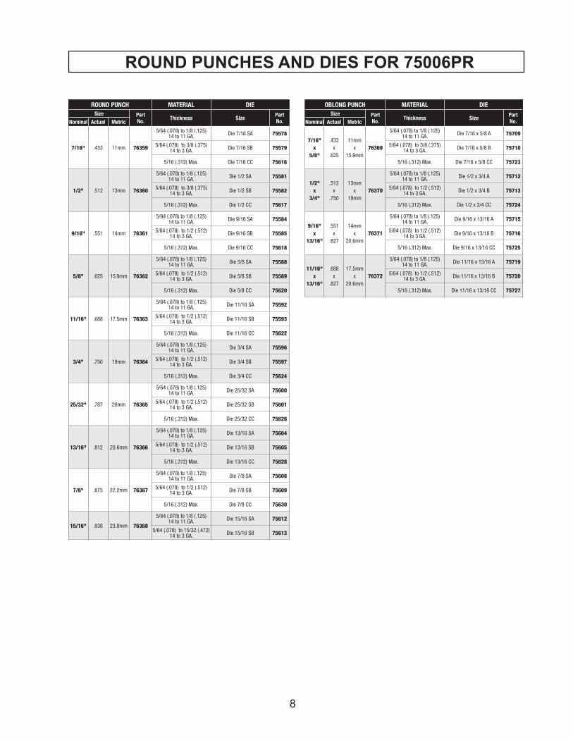
ROUND PUNCHES AND DIES FOR 75006PR
8
ROUND PUNCH MATERIAL DIESize Part
No. Thickness Size PartNo.Nominal Actual Metric
7/16" .433 11mm 76359
5/64 (.078) to 1/8 (.125)14 to 11 GA. Die 7/16 SA 75578
5/64 (.078) to 3/8 (.375)14 to 3 GA. Die 7/16 SB 75579
5/16 (.312) Max. Die 7/16 CC 75616
1/2" .512 13mm 76360
5/64 (.078) to 1/8 (.125)14 to 11 GA. Die 1/2 SA 75581
5/64 (.078) to 3/8 (.375)14 to 3 GA. Die 1/2 SB 75582
5/16 (.312) Max. Die 1/2 CC 75617
9/16" .551 14mm 76361
5/64 (.078) to 1/8 (.125)14 to 11 GA. Die 9/16 SA 75584
5/64 (.078) to 1/2 (.512)14 to 3 GA. Die 9/16 SB 75585
5/16 (.312) Max. Die 9/16 CC 75618
5/8" .625 15.9mm 76362
5/64 (.078) to 1/8 (.125)14 to 11 GA. Die 5/8 SA 75588
5/64 (.078) to 1/2 (.512) 14 to 3 GA. Die 5/8 SB 75589
5/16 (.312) Max. Die 5/8 CC 75620
11/16" .688 17.5mm 76363
5/64 (.078) to 1/8 (.125)14 to 11 GA. Die 11/16 SA 75592
5/64 (.078) to 1/2 (.512) 14 to 3 GA. Die 11/16 SB 75593
5/16 (.312) Max. Die 11/16 CC 75622
3/4" .750 19mm 76364
5/64 (.078) to 1/8 (.125)14 to 11 GA. Die 3/4 SA 75596
5/64 (.078) to 1/2 (.512)14 to 3 GA. Die 3/4 SB 75597
5/16 (.312) Max. Die 3/4 CC 75624
25/32" .787 20mm 76365
5/64 (.078) to 1/8 (.125)14 to 11 GA. Die 25/32 SA 75600
5/64 (.078) to 1/2 (.512)14 to 3 GA. Die 25/32 SB 75601
5/16 (.312) Max. Die 25/32 CC 75626
13/16" .812 20.6mm 76366
5/64 (.078) to 1/8 (.125)14 to 11 GA. Die 13/16 SA 75604
5/64 (.078) to 1/2 (.512)14 to 3 GA. Die 13/16 SB 75605
5/16 (.312) Max. Die 13/16 CC 75628
7/8" .875 22.2mm 76367
5/64 (.078) to 1/8 (.125)14 to 11 GA. Die 7/8 SA 75608
5/64 (.078) to 1/2 (.512)14 to 3 GA. Die 7/8 SB 75609
5/16 (.312) Max. Die 7/8 CC 75630
15/16" .938 23.8mm 76368
5/64 (.078) to 1/8 (.125)14 to 11 GA. Die 15/16 SA 75612
5/64 (.078) to 15/32 (.472)14 to 3 GA. Die 15/16 SB 75613
OBLONG PUNCH MATERIAL DIESize Part
No. Thickness Size PartNo.Nominal Actual Metric
7/16"x
5/8"
.433x
.625
11mmx
15.9mm76369
5/64 (.078) to 1/8 (.125)14 to 11 GA. Die 7/16 x 5/8 A 75709
5/64 (.078) to 3/8 (.375)14 to 3 GA. Die 7/16 x 5/8 B 75710
5/16 (.312) Max. Die 7/16 x 5/8 CC 75723
1/2"x
3/4"
.512x
.750
13mmx
19mm76370
5/64 (.078) to 1/8 (.125)14 to 11 GA. Die 1/2 x 3/4 A 75712
5/64 (.078) to 1/2 (.512)14 to 3 GA. Die 1/2 x 3/4 B 75713
5/16 (.312) Max. Die 1/2 x 3/4 CC 75724
9/16"x
13/16"
.551x
.827
14mmx
20.6mm76371
5/64 (.078) to 1/8 (.125)14 to 11 GA. Die 9/16 x 13/16 A 75715
5/64 (.078) to 1/2 (.512)14 to 3 GA. Die 9/16 x 13/16 B 75716
5/16 (.312) Max. Die 9/16 x 13/16 CC 75725
11/16"x
13/16"
.688x
.827
17.5mmx
20.6mm76372
5/64 (.078) to 1/8 (.125)14 to 11 GA. Die 11/16 x 13/16 A 75719
5/64 (.078) to 1/2 (.512)14 to 3 GA. Die 11/16 x 13/16 B 75720
5/16 (.312) Max. Die 11/16 x 13/16 CC 75727

9
TROUBLE SHOOTINGMELBORP ESUAC NOITULOS
TUBSNURROTOMSEODNOTSIPHCNUP
TUOEMOCTON
NEPOSIEVLAVNRUTERLAUNAM EVLAVNRUTERLAUNAMESOLC
TNEICIFFUSNISILIO LIODDA
DENRUTERTONSAHNOTSIPEMOHSTIOTYLETELPMOC
,SPIHCLEETSOTEUDNOITISOPEHTNOSIRBEDREHTOROTRID
REDLOH-HCNUPDESOPXE.NOITISOP
DESOPXEMORFSIRBEDNAELCFONOITROPREDLOH-HCNUP
NOTSIPHCNUPHSUP.DORNOTSIP.NOITISOPEMOHSTIOTKCAB
SIGNIRPSNRUTERNOTSIPHCNUPDORHCNUPNRUTEROTKAEWOOT
EHTYBDECIVRESENIHCAMEVAHYROTCAF
SEMOCNOTSIPHCNUPGNIHCNUPTUB,TUOKAEWOOTSIREWOP
HCNUPOT
TONSIEVLAVNRUTERLAUNAMDESOLCYLETELPMOC
EVLAVNRUTERLAUNAMESOLC
SIRIAROTNEICIFFUSNISILIORIOVRESERNIDEPPART
LIODDA
STRAPNOTSIPROPMUPLANRETNIDEGAMADROYTRID,NROWERAYLREPORPGNINOITCNUFTONDNA
EHTYBDECIVRESENIHCAMEVAHYROTCAF
TONSEODROTOMROOPROETATOR
ROTOMFONOITATOR
TIUCRICREWOPNEPO,DROCNOISNETXE,GULPKCEHC
REKAERBTIUCRIC
EGATLOVREPORPMI ECRUOSREWOPKCEHC
PORDEGATLOVEVISSECXEFOERASDROCNOISNETXE
EHTROFEZISERIWTNEICIFFUSNI.DROCEHTFOHTGNEL
ROSDROCDEGAMADRONROW.SEHSURBNOBRACNROW.SGULPSTRAPROTOMLANRETNIDEGAMAD
EHTYBDECIVRESENIHCAMEVAHYROTCAF
NEEWTEBGNIKAELLIODNAEMARF"C"
NEEWTEBROREDNILYCPMUPDNAREDNILYC
GNISUOH
THGITTONERASTLOB STLOBNETHGIT
DEGAMADSITEKSAGEHTYBDECIVRESENIHCAMEVAH
YROTCAF
DNUORAGNIKAELLIOMORFRONOTSIPAERALANRETNI
SECAFRUSROSLAESLANRETNIKCASRELEVELLIO.DEGAMADERA
NEKORBSI
EHTYBDECIVRESENIHCAMEVAHYROTCAF
TONSEODHCNUPFOTUOPIRTS
RETFAECEIPKROWGNIHCNUP
NROWSIEIDROHCNUP ECALPER
ROLAIRETAMROFEIDREPORPMISSENKCIHT
DNAHCNUPREPORPROFKCEHCNOITCELESEID
HTOBREDNUTONSAWECEIPKROWROGNIDNIBSIDNASREPPIRTS
HCNUP
SILAIRETAMEHTTAHTERUSEKAMGNIHCNUPEHTNIDETAESYLLUF
AERA

10
NOTE: The internal components of the pump and piston area have very close clearances and are sensitive to damage from dust, dirt, contamination of the hydraulic fluid or improper handling. The disassembly of the pump housing requires special tools and training, and should be attempted by a qualified repair person. The improper servicing of electrical components can lead to conditions that could cause serious injury.
ANY ATTEMPT BY UNAUTHORIZED PERSONNEL TO SERVICE THE INTERNAL COMPONENTS OF THE PUMP AREA WILL VOID THE WARRANTY.
In order to insure smoother operation and longer life of your hole puncher, the following maintenance should be done periodically, based on use.
1. Keep the machine clean. It is especially important to keep the sliding portion of the punch piston free from metal chips, scale, dirt, dust or other debris. To clean the punch piston, turn on the switch to move the punch piston almost to the bottom of its stroke. If necessary, cycle the punch several times to determine where the bottom of the stroke is, and to correctly position the punch piston.
Unplug the power cord. Wipe any debris from the ex-posed part of the punch piston.
2. Regularly tighten all fasteners and replace anyworn components.
3. Check power cord, if cracked or frayed, return the machine to an authorized repair center forreplacement.
4. Check oil level, carefully using the procedure below.
ADDING OIL4. Carefully open the oil port by removing the sockethead cap screw.
5. Using the small squeeze bottle supplied with theHole Puncher, carefully add hydraulic oil to completelyfill the reservoir. Rock the Hole Puncher back and forthslightly several times to free any trapped air bubbles,then add additional oil if necessary.
6. Replace the cap screw and wipe up any excess oil.
7. Cycle the Hole Puncher several times with the Manual return Valve open, and again with the valve closed, to work any trapped air out of the system, then repeat the above procedure, making sure that the punch piston is almost at the bottom of the stroke before removing the cap screw from the oil port.
8. Add additional oil as necessary. If the unit was extremely low on oil, it may be necessary to repeatthe procedure several times.
MAINTENANCE
HELPFUL HINTS FOR HOLE PUNCHINGEach of the punches is provided with a sharp point at itscenter. If the hole locations are center punched, the pointon the end of the punch may be used to "find" the centerpunched spot.
Also, for accurate and easy positioning of the punch to ahole location, the switch can be intermittently pulsed onan off to jog the punch down to the work surface.
If the position is not satisfactory, open the manual returnvalve to retract the punch for another attempt. Thisoperation can also be performed with the manual returnvalve "cracked" open slightly to prevent full punchingpressure from being developed. In this manner, thepunch can be easily brought right down to the surfacewithout beginning to punch the hole. If the location is satidfactory, close the valve and finish the operation.
Use of the correct hydraulic oil is essential. Approved oils are Shell "TELLUS Oil" and Exxon "TERESSTIC" (PartNo. 75377). Grade #32 viscosity must be used. Check the unit specifications. Make sure that the work area and all equipment are clean so that no dirt, dust or other foreign material can get into the hydraulic oil or pump area.
1. Locate the socket head cap screw that plugs the oil port. It is just above the manual return lever on the right hand side of the Hole Puncher.
2. Lay the Hole Puncher on its left side so that the oil port is facing up.
3. Turn on the switch to move the punch piston almost to the bottom of its stroke. If necessary, cycle the punch several times to determine where the bottom of the stroke is, and to correctly position the punch piston. In this posi-tion, the maximum amount of oil has been drawn from the pump and the correct fill can be obtained.
WARNING! Failure to check punch retaining nut periodically during use, can result inpersonal injury or damage to your unit.

11
NOTES
Hougen Manufacturing, Incorporated warrants its Portable Magnetic Drills, Electro-hydraulic Hole Punchers for a period of (1) one year and other products for ninety (90) days from date of purchase against defects due to faulty material or workmanship and will repair or replace (at its option) without charge any items returned. This warranty is void if the item has been damaged by accident or unreasonable use, neglect, improper service, or other causes not arising out of defects in material or workmanship. No other expressed warranty is given or authorized. Hougen Manufacturing, Inc. disclaims any implied warranty of MERCHANTABILITY or FITNESS for any period beyond the expressed warranty and shall not be liable for incidental or consequential damages. Some states do not allow exclusions of incidental or consequential damages or limitation on how long an implied warranty lasts and, if the law of such a state governs your purchase, the above exclusion and limitation may not apply to you. This warranty gives you specific legal rights and you may also have other rights which vary from state to state.
To obtain warranty service, return the item(s), transportation prepaid, to your nearest Factory Authorized Repair Center or to Hougen Manufacturing, Inc., 3001 Hougen Drive, Swartz Creek, Michigan 48473. Hougen Drills and Cutter are warranted against manufacturing defects only. Subject to HougenManufacturing inspection.
THIS WARRANTY IS IN LIEU OF ANY OTHER WARRANTY, EXPRESSED OR IMPLIED, INCLUDING ANYWARRANTY OF MERCHANTABILITY OR FITNESS FOR A PARTICULAR PURPOSE© 2015 Hougen Manufacturing, Inc.
Commercial / Industrial Limited Warranty
Photographs and Specifications shown are accurate in detail at time of printing. Manufacture reserves the right to make improvements and modifications without prior notice.Hougen, Hougen-Edge, Punch-Pro, and the Hougen logo are proprietary trademarks of Hougen Manufacturing, Inc. Ogura and Ogura logo are proprietary trademarks of Ogura & Co., Ltd.
Hougen-Ogura Patent Notice
Factory Warranty Repair Servicescan be obtained by sending your product to:
Hougen Manufacturing, Inc.3001 Hougen Drive
Swartz Creek, MI 48473Attn: Repair Department
Hougen Manufacturing, Inc.P.O. Box 2005 Flint, MI 48501-20053001 Hougen Drive • Swartz Creek, MI 48473Phone (810) 635-7111 Fax (810) 635-8277www.hougen.com • [email protected]© 2015 Hougen Manufacturing, Inc.


