15
PORTABLE MAGNETIC DRILL FOR USE WITH "42,000/43,000-SERIES" CUTTERS HMD915 SERIES OPERATOR’S MANUAL COVERS DRILL PART NUMBERS 0915102, 0915202, 0915302, 0915402 OM9151013 Printed in U.S.A.

PORTABLE MAGNETIC DRILL
FOR USE WITH "42,000/43,000-SERIES" CUTTERS
HMD915 SERIES
OPERATOR’S MANUALCOVERS DRILL PART NUMBERS 0915102, 0915202, 0915302, 0915402
OM9151013 Printed in U.S.A.

HOUGEN® Portable Magnetic DrillsModel HMD915Wecome to HougenCongratulations on your purchase of the Hougen® Portable Magnetic Drill. Your model is designed to produce superior holes quickly and effeciently. Through constant innovation and development, Hougen is committed to provide you with hole-producing tools and products to help you be more productive.
Before attempting to operate your new Portable Magnetic Drill, please read all instructions first. These include the Operator’s Manual and Warning Label on the unit itself. With proper use, care, and maintenance, your model will provide you with years of effective hole drilling performance. Once again, thank you for selecting our product and welcome to Hougen.
2
Always wear eye protection while using cutting tools, or in the vicinity of cutting.
CAUTION! The slug is ejected at the end of the cut. Do not aim cutter or arbor so that ejected slug may hit someone around, or below you.
CAUTION! Cutters are sharp. Wear gloves when installing or removing cutter from arbor. Do not grab a rotating cutter.
CAUTION! To prevent electric shock, do not use power tools near wet areas, or where power tool may become wet.
SAFETY FIRST
Cutter Type........................Hougen "42/43,000-Series" "12,000-Series" w/adapterHole Capacity....................3/4" - 3-1/16" (19mm - 77mm) Depth of Cut......................3" (76mm)Drill RPM/Motor.................120/332 RPM, 10A (120V), 5A (230V)Net Weight.........................69 lb (31.3kg)
Specifications
INDEX
Welcome to Hougen 2 Panel Hookup Diagram 9-10Safety Instructions 3-4 Panel Parts Breakdown 11Operating Instructions 5 Motor Parts Breakdown 11
Impactor, Feed & Glide Post Adjustment 6 Exploded View 12-13Ejector Rod Adjustment 7 Drill Parts List 14-15Gear Combinations 7 Commercial / Industrial Limited Warranty 15Installing Cutter & Cutting Fluid 8 Warranty Repair Centers 16Hints for Smoother Operation 8
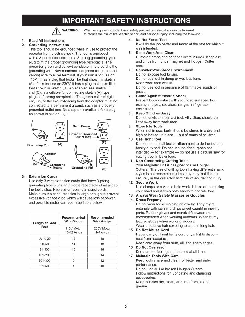
1. Read All Instructions2. Grounding Instructions This tool should be grounded while in use to protect the operator from electric shock. The tool is equipped with a 3-conductor cord and a 3-prong grounding type plug to fit the proper grounding type receptacle. The green (or green and yellow) conductor in the cord is the grounding wire. Never connect the green (or green and yellow) wire to a live terminal. If your unit is for use on 115V, it has a plug that looks like that shown in sketch (A). If it is for use on 230V, it has a plug that looks like that shown in sketch (B). An adapter, see sketch and (C), is available for connecting sketch (A) type plugs to 2-prong receptacles. The green-colored rigid ear, lug, or the like, extending from the adapter must be connected to a permanent ground, such as a properly grounded outlet box. No adapter is available for a plug as shown in sketch (D).
3. Extension Cords Use only 3-wire extension cords that have 3-prong grounding type plugs and 3-pole receptacles that accept the tool’s plug. Replace or repair damaged cords. Make sure the conductor size is large enough to prevent excessive voltage drop which will cause loss of power and possible motor damage. See Table below.
3
4. Do Not Force Tool It will do the job better and faster at the rate for which it was intended.5. Keep Work Area Clean Cluttered areas and benches invite injuries. Keep dirt and chips from under magnet and Hougen Cutter area.6. Consider Work Area Environment Do not expose tool to rain. Do not use tool in damp or wet locations. Keep work area well lit. Do not use tool in presence of flammable liquids or gases.7. Guard Against Electric Shock Prevent body contact with grounded surfaces. For example: pipes, radiators, ranges, refrigerator enclosures.8. Keep Children Away Do not let visitors contact tool. All visitors should be kept away from work area.9. Store Idle Tools When not in use, tools should be stored in a dry, and high or locked-up place — out of reach of children.10. Use Right Tool Do not force small tool or attachment to do the job of a heavy duty tool. Do not use tool for purpose not intended — for example — do not use a circular saw for cutting tree limbs or logs.11. Non-Conforming Cutting Tools Your Magnetic Drill is designed to use Hougen Cutters. The use of drilling tools having different shank styles is not recommended as they may not tighten securely in the drill arbor with risk of accident or injury.12. Secure Work Use clamps or a vise to hold work. It is safer than using your hand and it frees both hands to operate tool.13. Always Wear Safety Glasses or Goggles14. Dress Properly Do not wear loose clothing or jewelry. They might entangle with spinning chips or get caught in moving parts. Rubber gloves and nonskid footwear are recommended when working outdoors. Wear sturdy leather gloves when working indoors. Wear protective hair covering to contain long hair.15. Do Not Abuse Cord Never carry drill unit by its cord or yank it to discon- nect from receptacle. Keep cord away from heat, oil, and sharp edges.16. Do Not Overreach Keep proper footing and balance at all time.17. Maintain Tools With Care Keep tools sharp and clean for better and safer performance. Do not use dull or broken Hougen Cutters. Follow instructions for lubricating and changing accessories. Keep handles dry, clean, and free from oil and grease.
WARNING: When using electric tools, basic safety precautions should always be followed to reduce the risk of fire, electric shock, and personal injury, including the following:
IMPORTANT SAFETY INSTRUCTIONS
Grounding Pin (A)
(C)
(D)
(B)
Adapter
GroundingMeans Grounding Pin
Metal Screw
Cover of GroundedOutlet Box
Length of CordFeet
RecommendedWire Gauge
RecommendedWire Gauge
115V Motor10-12 Amps
230V Motor4-6 Amps
Up to 25 16 18
26-50 14 18
51-100 10 16
101-200 8 14
201-300 5 12
301-500 4 10

4
Continued... Inspect tool cords periodically and, if damaged, have repaired by authorized service facility. Inspect extension cords periodically and, if damaged, have repaired by authorized service facility.18. Disconnect Tools Disconnect when not in use, before servicing, and when changing Hougen Cutters or accessories.19. Remove Adjusting Keys and Wrenches Form a habit of checking to see that keys and wrenches are removed from tool before turning it on.20. Check Damaged Parts Before further use of the drill, a part that is damaged should be carefully checked to determine that it will operate properly and perform its intended function. Check for alignment of moving parts, binding of moving parts, breakage of parts, mounting, and any other conditions that may affect its operation. A part that is damaged should be properly repaired or replaced by an authorized service center unless otherwise indicated elsewhere in this operator manual. Do not operate tool if switch does not turn it on and off.21. Stay Alert Watch what you are doing. Use common sense. Do not operate tool when you are tired. Have defective switches replaced by authorized service center.22. Outdoor Use Extension Cords When tool is used outdoors, use only extension cords intended for use outdoors and so marked.23. Additional Safety Precautions Spindle and cutter should never be used as a hand- hold. Keep hands and clothing away from all moving parts. Do not use Hougen Cutters where ejected slug might cause injury (slug ejected at end of cut). Be sure that all safety devices are properly adjusted and in use. Also, adhere to all operating instructions. Do not drill through any surface that may contain live electrical wiring. Drilling into a live wire could cause exposed metal parts of the drill to be made live. Remove chips wrapped around Hougen Cutter and arbor after each hole. With motor off and power disconnected, grasp chips with leather gloved hand or pliers and pull while rotating counter-clockwise. Should the cutter become jammed in the work, stop the unit immediately to prevent personal injury. Disconnect the drill from the power supply and loosen jammed cutter by turning the arbor counterclockwise. Never attempt to free the jammed cutter by starting the motor. Service at authorized repair center only.24. Operating Near Welding Equipment It is NOT recommended that you use this tool on the same work surface as an arc welder. This can cause severe damage to the unit, particularly the power cord. This could also result in personal injury to the operator.
25. Safe Electrical Connection Wet electrical connections are shock hazards. To prevent the cutting fluid from traveling along the cord and contacting the plug or power outlet, tie a drip loop as shown at below. Also elevate extension cords or gang box connections.
26. Save These Instructions
IMPORTANT SAFETY INSTRUCTIONS - CONTINUED

5
Always remember that the magnet’s holding power is directly related to the workpiece thickness and surfacecondition. This drill is for use on 3/8" material or thicker. Since magnetic attraction diminshes with thinner material or rough surfaces, mechanical clamping of drill unit to the workpiece should be used when cutting such material.
1. Make sure workpiece and bottom of magnet are free chips, oil, etc.
2. Attach Safety Chain (particularly when operating on beams, horizontally, vetically, etc.)
3. Position drill by sliding it so that point of the ejector rod is above center of hole to be drilled.
4. Turn Magnet switch to ON position.
5. Set both impactors into the workpiece by striking with hammer.
6. Open the Adjustment Needle to provide a generous flow of cutting fluid until a puddle approximately the diameter of the cutter being used is developed on the workpiece. Once this initial supply of cutting fluid is established on the workpiece, adjust the flow to a steady drip.
7. Make certain that cutter is clear of workpiece and turn motor switch ON.
8. Feed Hougen Cutter slowly into workpiece. Only after cutting path is established to a depth of about 1/16" can full feed force be applied to feed handles.
9. Ease up on feed pressure as cutter starts breaking through.
10. At conclusion of cut, turn Motor OFF. Turn feed handles to raise Arbor, thereby ejecting the slug if it hasn’t already fallen free.
11. Turn Magnet OFF and give switch a quick flip to the DEMAG position, allowing it to snap back to center or OFF position. (Do not hold switch in DEMAG position)
12. Remove chips from both cutter and magnet. Preferably while wearing leather work gloves.
13. Disconnect safety chain and you are ready to move unit to new position.
SPECIAL INSTRUCTION FOR HORIZONTALOR OVERHEAD OPERATION
1. Always use Safety Chain and / or mechanical clamping.
2. Use grease or animal fat base solid lubricant applied liberally to cutter.
OPERATING INSTRUCTIONS
1. Open shipping carton and remove the literature and hardware packages.2. Read and follow all instructions before attempting to operate your new Magnetic Drill.3. Complete and mail the Product Registration Card NOW. It is important that Hougen Mfg., Inc. have a record of product ownership.4. Contents of Tool Box (40100) 10730 - Safety Chain 10569 - Feed Handles (3) 04532 - Knobs (3) 10565 - Hex Key 1/8" S.A. 13013 - Wrench Allen 5/32" 10779 - Wrench Allen 7/32" 10727 - Wrench Allen 3/16" 10780 - Wrench Allen 5/16" 10781 - Wrench Allen 3/8" 40040 - Adapter Assembly 40041 - Screw-Soc Set 5/8-11 40042 - Screw-Soc Set 3/4-10 (2) 40061 - Handle Assembly 05487 - Grease - Lubriplate GR-132 40126 - Coolant Btl. Assembly * *(sometimes packed separately)
5. Lift the unit out of the shipping case.6. Remove all packing and securing material from the drill unit.7. Screw the three knobs (10570) onto the three feed handles (10569) and then screw the handles into the hub.8. Install coolant bottle on unit, utilizing screws that are provided9. Your Magnetic Drill was factory adjusted prior to shipping. Check to make sure that the feed rod adjust- ment screws, motor mount screws, exterior bolts and screws have not vibrated loose in transit.10. Your New Magnetic Drill comes complete and ready to go. This unit utilizes the "42,000 and 43,000"- Series Cutters either with the 1-1/4" shank or the "12,000-Series" 3/4" shank cutters.
UNPACKING YOUR NEW MAGNETIC DRILL

Drag Screw (Detail No 63A) must be adjusted againstthe Feed Rod (Detail No.13) so that main housing (Detail No. 63) moves freely up and down the feed rods when feed wheel is turned, so that main housingstays in position on feed rod when wheel is released.
6
1. Adjustment is made with Magnet ON and impactor over the work surface.
2. Loosen Heads of Front and Rear Impactors (Detail No. 25)
3. Screw Impactor Points (Detail No. 26) up (counter- clockwise) until point just touches work surface.
4. Screw Impactors down (clockwise) until point just touches work surface.
5. Screw Impactor Points 1/2 turn further toward work surface. (It may be necessary to turn off Magnet while advancing Impactor).
6. Tighten Heads.
FEED ADJUSTMENT
GLIDE POST ADJUSTMENT
IMPACTOR ADJUSTMENT
1. Adjustment is made with magnet on and glide posts over work surface.
2. Remove front glide post lock screw (Detail No. 27), and loosen rear glide post lock screw (Detail No. 51).
3. Screw both glide posts (Detail No. 28 & 50) up until the ends are above the work surface.
4. Place a .040" shim under the front glide post and a 0.125" shim under the rear glide post.
5. Screw glide posts down, compressing plungers, until the body of the glide posts rest on the shims.
6. Replace the front lock screw and tighten both the front and rear lock screws.
ImpactorHead
ImpactorPoint
Drag Screw
Lock ScrewLock Screw
Glide Posts
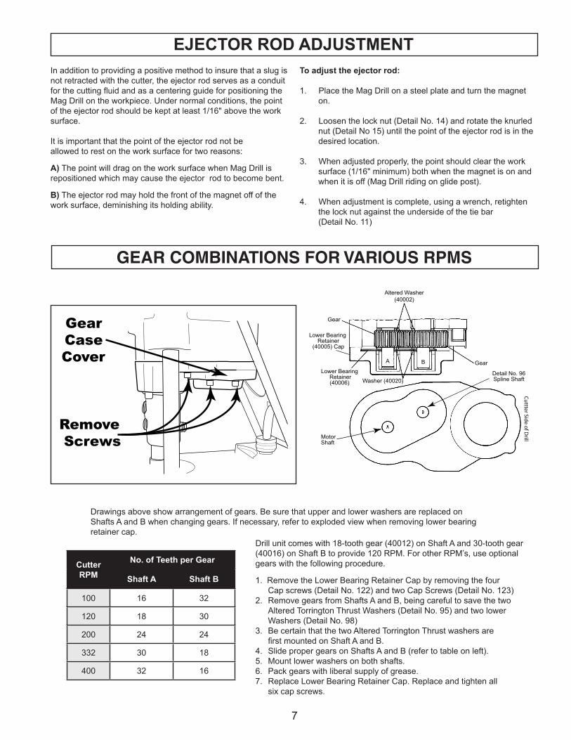
Drawings above show arrangement of gears. Be sure that upper and lower washers are replaced on Shafts A and B when changing gears. If necessary, refer to exploded view when removing lower bearing retainer cap.
Drill unit comes with 18-tooth gear (40012) on Shaft A and 30-tooth gear(40016) on Shaft B to provide 120 RPM. For other RPM’s, use optional gears with the following procedure.
1. Remove the Lower Bearing Retainer Cap by removing the four Cap screws (Detail No. 122) and two Cap Screws (Detail No. 123)2. Remove gears from Shafts A and B, being careful to save the two Altered Torrington Thrust Washers (Detail No. 95) and two lower Washers (Detail No. 98)3. Be certain that the two Altered Torrington Thrust washers are first mounted on Shaft A and B.4. Slide proper gears on Shafts A and B (refer to table on left).5. Mount lower washers on both shafts.6. Pack gears with liberal supply of grease.7. Replace Lower Bearing Retainer Cap. Replace and tighten all six cap screws.
7
GEAR COMBINATIONS FOR VARIOUS RPMS
In addition to providing a positive method to insure that a slug is not retracted with the cutter, the ejector rod serves as a conduit for the cutting fluid and as a centering guide for positioning the Mag Drill on the workpiece. Under normal conditions, the point of the ejector rod should be kept at least 1/16" above the work surface. It is important that the point of the ejector rod not beallowed to rest on the work surface for two reasons:
A) The point will drag on the work surface when Mag Drill is repositioned which may cause the ejector rod to become bent.
B) The ejector rod may hold the front of the magnet off of the work surface, deminishing its holding ability.
EJECTOR ROD ADJUSTMENT
MotorShaft
Detail No. 96Spline Shaft
Cu
ttter Side o
f Drill
Gear
Altered Washer(40002)
GearB
A B
Lower Bearing Retainer
(40005) Cap
Lower Bearing Retainer(40006) Washer (40020)
To adjust the ejector rod:
1. Place the Mag Drill on a steel plate and turn the magnet on. 2. Loosen the lock nut (Detail No. 14) and rotate the knurled nut (Detail No 15) until the point of the ejector rod is in the desired location.
3. When adjusted properly, the point should clear the work surface (1/16" minimum) both when the magnet is on and when it is off (Mag Drill riding on glide post).
4. When adjustment is complete, using a wrench, retighten the lock nut against the underside of the tie bar (Detail No. 11)
GearCaseCover
Remove Screws
CutterRPM
No. of Teeth per Gear
Shaft A Shaft B
100 16 32
120 18 30
200 24 24
332 30 18
400 32 16

8
INSTALLING CUTTER IN SPINDLE OPERATION OF CUTTING FLUID RESERVOIR
1. Jog motor until appropriate set screws are accessible. 2. Either lay drill on its side with feed wheel up, or be sure Spindle sure Spindle clears table if unit is in normal operation position.
3. A) Hougen Cutters with 1-1/4" dia. shanks
Loosen the two short set screws (40040) and insert insert cutter shank being certain that the flats are aligned with the set screw holes. Tighten the lower set screw first and then tighten the upper set screw. (Be sure the long set screw on opposite side of spindle has been removed.
B) Hougen Cutters with 3/4" dia. shanks
Install the spindle adapter (40040) using the same procedure as used when mounting cutters with 1-1/4" diameter shanks. Slip the Cutter Shank into the adapter so that the flat on its shank is aligned with the single set screw hole. Install the long set screw (40041) and tighten.
C) "12,000-Series" Shanks When using "12,000-Series" shank cutters, DO NOT us the long set screws (40041). Install cutter adapter (40040) using the two small set screws lining up the two flats. Install adapter into quill and secure using set screws (40042).
4. Check periodically during operation to be certain
that the cutter is secure.
When everything is ready to go (Magnet ON and Impactors seated), open the Adjustment Needle to provide a generous flow of cutting fluid until a puddle approximately the diameter of the cutter being used is developed on the workpiece.Oncethis initial supply of cutting fluid is established on the workpiece, adjust the flow to a steady drip.
ADJUSTMENT OF CHIPBREAKER
Adjust the chipbreaker blade to within .020" to .030" of cutter and tighten securely.
HINTS FOR SMOOTHER OPERATION
1. Keep inside of Hougen Cutter clear of chips.Chips will interfere with cutting to maximum depth, may impede the free flow of cutting fluid and can cause cutter breakage.
2. Keep work, machine, arbor and Hougen Cutter free of chips and dirt.
3. Tighten all fasteners periodically.4. We highly recommend using a light cutting fluid
(preferbly Hougen Cutting Fluid)5. Occasionally check metering of cutting fluid flow. Lack of
cutting fluid may cause Hougen Cutter to freeze in cut, slug to stick and may result in poor cutter life.
6. Always start cut with light feed pressure and then increase sufficiently to achieve maximumcutting rate.
7. Ease off on pressure as cutter begins to break through at end of cut.
8. When slug hangs up in cutter, bring cutter down on a flat surface. This will normally straighten a cocked slug,
allowing it to be ejected.9. Cut overlapping holes using minimum steady pressure.
(External lubrication should be used)
Note: When cutting in this manner, cutting fluidmay escape from cutting area. Tool should be fed with care, using external lubrication
Set Screws(40042)
1-1/4" Diam. Shank Rotabroach Cutter
Ejector Rod Point(40114)
3/4" Diam. Shank Rotabroach Cutter
Set Screw(40041)
Spindle Adapter(40040)
Spindle(40031)
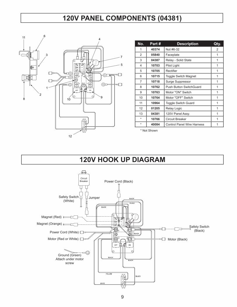
Ground (Green) Attach under motor
screw
Motor (Red or White)
Power Cord (White)
Safety Switch (Black)
Motor (Black)
Power Cord (Black)
Jumper
Magnet (Red)
Magnet (Orange)
Safety Switch (White)
Circuit Breaker
9
ONOFF
1413
129
85
41
1
23
4
BLK.
-
+
611
3
82
109
5
7
4
1
12
120V HOOK UP DIAGRAM
120V PANEL COMPONENTS (04381)
No. Part # Description Qty.1 40374 Nut #6-32 2
2 05840 Faceplate 1
3 04387 Relay - Solid State 1
4 10703 Pilot Light 1
5 10705 Rectifier 1
6 10715 Toggle Switch Magnet 1
7 10718 Surge Suppressor 1
8 10762 Push Button SwitchGuard 1
9 10763 Motor "ON" Switch 1
10 10764 Motor "OFF" Switch 1
11 10964 Toggle Switch Guard 1
12 01205 Relay Logic 1
13 04381 120V Panel Assy. 1
* 10766 Circuit Breaker 1
* 40084 Control Panel Wire Harness 1
ONOFF
1413
129
85
41
1
23
4
BLK.
-
+
611
3
82
109
5
7
4
1
12
* Not Shown

Ground (Green)Attach under motor
screw
Motor (Red or White)
Power Cord (White)
Safety Switch(Black)
Motor (Black)
Power Cord (Black)
Jumper
Magnet (Red)
Magnet (Orange)
Safety Switch(White)
CircuitBreaker
230V PANEL COMPONENTS (10796)
10
ONOFF
1413
129
85
41
1
23
4
BLK.
-
+
2530
22
2721
2928
24
26
23
20
31
230V HOOK UP DIAGRAM
* Not Shown
No. Part # Description Qty.20 40374 Nut #6-32 2
21 05840 Faceplate 1
22 04387 Relay - Solid State 1
23 10703 Pilot Light 1
24 10705 Rectifier 1
25 10715 Toggle Switch Magnet 1
26 10760 Surge Suppressor 1
27 10762 Push Button SwitchGuard 1
28 10763 Motor "ON" Switch 1
29 10764 Motor "OFF" Switch 1
30 10964 Toggle Switch Guard 1
31 01005 Relay Logic 1
32 10796 230V Panel Assy. 1
* 10785 Circuit Breaker 1
* 40084 Control Panel Wire Harness 1
ONOFF
1413
129
85
41
1
23
4
BLK.
-
+
2530
22
2721
2928
24
26
23
20
31

33*1
2
3
4
5
6
7
8
9
10
11
12
13
14
15
30,31,32
28,29
27
26
25
24
2322
212019
18
36,3734,35
40
39
38
44 41
42
45
43
11
MOTOR PARTS
No. Part # Description Qty1 BD-14201 Ball Bearing 1
2 BD-30612 Bearing Plug 1
3 BD-31675 Set Screw 2
4 BD-475 3/16” Ball 1
5 BD-38769 Dentent Pin Spring 1
40140 Lock Pin 1
6 07224 Field - 120V 1
BD-450070-00 Field - 230V 1
7 07223 Armature - 120V 1
BD-450063-42 Armature - 230V 1
8 BD-330003-12 Ball Bearing 1
9 BD-21635 Needle Bearing 1
10 40000 Output Shaft 1
11 BD-70920 Lock Nut 1
12 BD-45051 Cone Lock Washer 1
13 BD-55196 Spindle Gear 1
14 BD-13851 Spindle Gear Key 1
15 BD-38219 Bearing Cap 1
18 BD-30090 Ball Bearing 1
19 BD-38278 1st Internal Pinion 1
20 BD-6952 1st Internal Gear Key 1
21 BD-38210 1st Internal Gear 1
22 BD-939467-00 Gasket 1
No. Part # Description Qty23 BD-30613 Bearing Plug 1
24 BD-20774-01 Ball Bearing 1
25 BD-24323 Insulating Shield 2
26 BD-33880-81 Brush Holder Cap 2
27 10583 Brush (Pair) 1
28 BD-38226 Brush Lead 2
29 BD-9293 Brush Lead Terminal 2
30 BD-38225 Contact Block Assy 1
31 BD-4006-01 Rivet 2
32 BD-38224 Contact 2
33 BD-54914-06 Spade Handle 1
34 BD-4145-01 Lock Washer 2
35 BD-37955 Screw 2
36 BD-9842 Screw 2
37 BD-416 Lock Washer 6
38 BD-37914 Insulating Spacer 2
39 BD-445694 Anit-Friction Ring 1
40 BD-38201-02 Reverse Switch Ring 1
41 BD-38221 Needle Bearing 1
42 BD-38218 Thurst Washer 1
43 BD-55401 Gear & Pinion Assy 1
44 BD-6952 2nd Internal Gear Key 1
45 BD-8068 Ball Bearing 1
12
113
114
115
130 131
134
118 11
9
120
133
125
126
128
129
132
127
123
122
133
26
41
52
79 80 81
88 89 90
101
100 99 98
97 96
98 84 98
91
9089 88
78 80 82 8283 85
98
30
32
39
3719
734
2223
24
262528
28
2733
2930
4825
132
49
4245
3159
35
6
40A
dapt
er fo
r "12
,000
-Ser
ies"
Cut
ters
2021
1819
106
107
108
22
104
31 110
111
112
116
11710
5
4*
3*2*
1*
6 7 5a*
11 1313
15
16
1412
10
8*
9*
5*6 7
7172
7361
756667
68
69
7064
6262
6161
17
63
94
62
61
51
69
7068
67
76
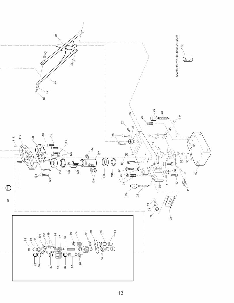
* In
clud
ed in
4012
6 A
ssem
bly
12
133
5655
135
136
137
138
139
HM
D91
5 Ex
plod
ed V
iew
13
113
114
115
130 131
134
118 11
9
120
133
125
126
128
129
132
127
123
122
133
26
41
52
79 80 81
88 89 90
101
100 99 98
97 96
98 84 98
91
9089 88
78 80 82 8283 85
98
30
32
39
3719
734
2223
24
262528
28
2733
2930
4825
132
49
4245
3159
35
6
40A
dapt
er fo
r "12
,000
-Ser
ies"
Cut
ters
2021
1819
106
107
108
22
104
31 110
111
112
116
11710
5
4*
3*2*
1*
6 7 5a*
11 1313
15
16
1412
10
8*
9*
5*6 7
7172
7361
756667
68
69
7064
6262
6161
17
63
94
62
61
51
69
7068
67
76
* In
clud
ed in
4012
6 A
ssem
bly
12
133
5655
135
136
137
138
139
14
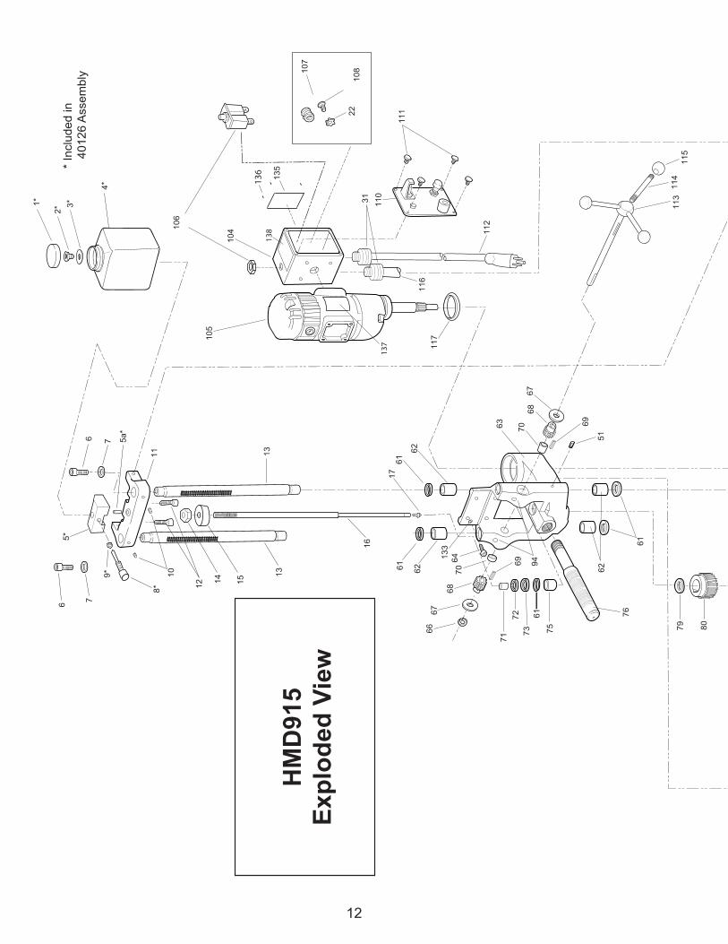
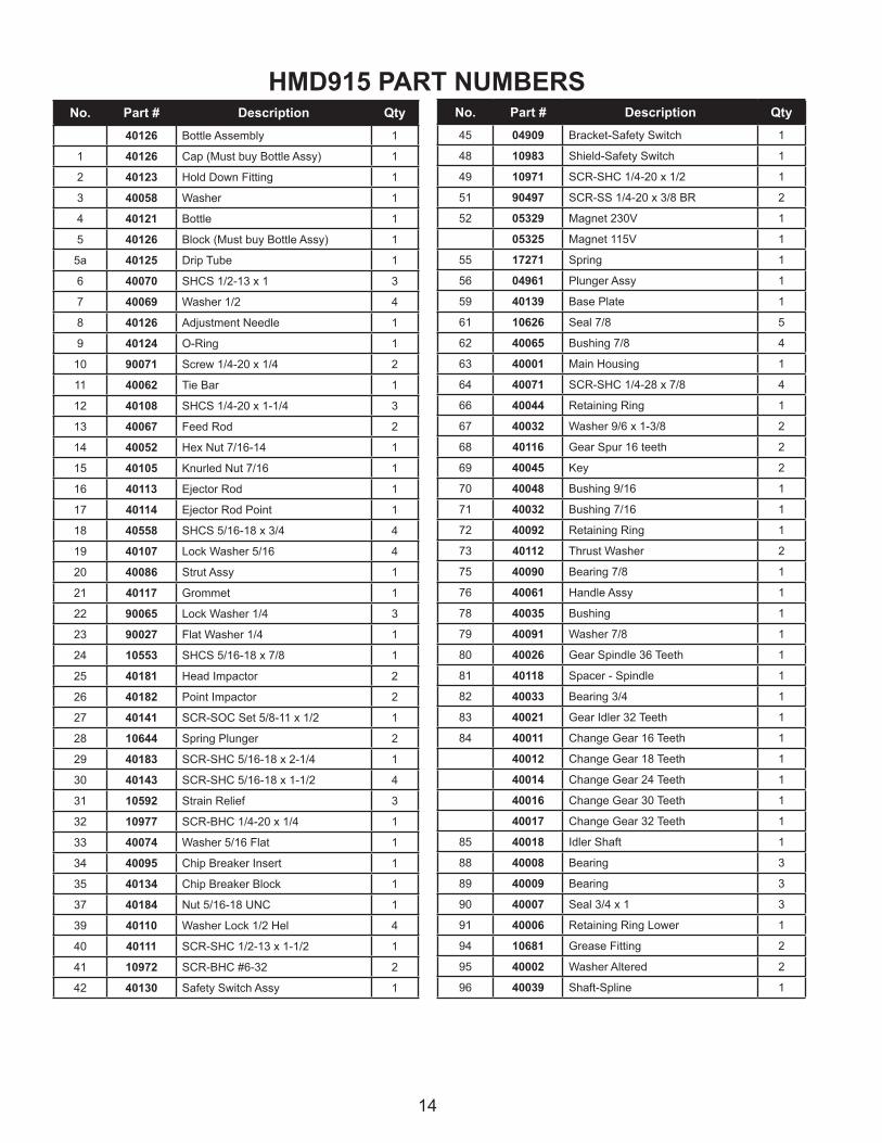
HMD915 PART NUMBERSNo. Part # Description Qty
40126 Bottle Assembly 1
1 40126 Cap (Must buy Bottle Assy) 1
2 40123 Hold Down Fitting 1
3 40058 Washer 1
4 40121 Bottle 1
5 40126 Block (Must buy Bottle Assy) 1
5a 40125 Drip Tube 1
6 40070 SHCS 1/2-13 x 1 3
7 40069 Washer 1/2 4
8 40126 Adjustment Needle 1
9 40124 O-Ring 1
10 90071 Screw 1/4-20 x 1/4 2
11 40062 Tie Bar 1
12 40108 SHCS 1/4-20 x 1-1/4 3
13 40067 Feed Rod 2
14 40052 Hex Nut 7/16-14 1
15 40105 Knurled Nut 7/16 1
16 40113 Ejector Rod 1
17 40114 Ejector Rod Point 1
18 40558 SHCS 5/16-18 x 3/4 4
19 40107 Lock Washer 5/16 4
20 40086 Strut Assy 1
21 40117 Grommet 1
22 90065 Lock Washer 1/4 3
23 90027 Flat Washer 1/4 1
24 10553 SHCS 5/16-18 x 7/8 1
25 40181 Head Impactor 2
26 40182 Point Impactor 2
27 40141 SCR-SOC Set 5/8-11 x 1/2 1
28 10644 Spring Plunger 2
29 40183 SCR-SHC 5/16-18 x 2-1/4 1
30 40143 SCR-SHC 5/16-18 x 1-1/2 4
31 10592 Strain Relief 3
32 10977 SCR-BHC 1/4-20 x 1/4 1
33 40074 Washer 5/16 Flat 1
34 40095 Chip Breaker Insert 1
35 40134 Chip Breaker Block 1
37 40184 Nut 5/16-18 UNC 1
39 40110 Washer Lock 1/2 Hel 4
40 40111 SCR-SHC 1/2-13 x 1-1/2 1
41 10972 SCR-BHC #6-32 2
42 40130 Safety Switch Assy 1
No. Part # Description Qty45 04909 Bracket-Safety Switch 1
48 10983 Shield-Safety Switch 1
49 10971 SCR-SHC 1/4-20 x 1/2 1
51 90497 SCR-SS 1/4-20 x 3/8 BR 2
52 05329 Magnet 230V 1
05325 Magnet 115V 1
55 17271 Spring 1
56 04961 Plunger Assy 1
59 40139 Base Plate 1
61 10626 Seal 7/8 5
62 40065 Bushing 7/8 4
63 40001 Main Housing 1
64 40071 SCR-SHC 1/4-28 x 7/8 4
66 40044 Retaining Ring 1
67 40032 Washer 9/6 x 1-3/8 2
68 40116 Gear Spur 16 teeth 2
69 40045 Key 2
70 40048 Bushing 9/16 1
71 40032 Bushing 7/16 1
72 40092 Retaining Ring 1
73 40112 Thrust Washer 2
75 40090 Bearing 7/8 1
76 40061 Handle Assy 1
78 40035 Bushing 1
79 40091 Washer 7/8 1
80 40026 Gear Spindle 36 Teeth 1
81 40118 Spacer - Spindle 1
82 40033 Bearing 3/4 1
83 40021 Gear Idler 32 Teeth 1
84 40011 Change Gear 16 Teeth 1
40012 Change Gear 18 Teeth 1
40014 Change Gear 24 Teeth 1
40016 Change Gear 30 Teeth 1
40017 Change Gear 32 Teeth 1
85 40018 Idler Shaft 1
88 40008 Bearing 3
89 40009 Bearing 3
90 40007 Seal 3/4 x 1 3
91 40006 Retaining Ring Lower 1
94 10681 Grease Fitting 2
95 40002 Washer Altered 2
96 40039 Shaft-Spline 1

15
HMD915 PART NUMBERS (CONT)No. Part # Description Qty97 40010 Driven Gear 16 Teeth 1
98 40020 Thrust Washer 4
99 40038 SHCS 10-32 x 5/8 2
100 10560 Washer #10 2
101 40037 Upper Retaining Ring 1
104 40083 Electrical Box 1
105 40082 120V Motor 1
40131 230V Motor 1
106 10766 Circuit Breaker 15A - 120V 1
10785 Circuit Breaker 8A - 230V 1
107 10771 Grommet 1
108 40066 SCR-BHC 1/4-28 3
110 10796 Panel Assy - 120V 1
04381 Panel Assy - 230V 1
111 10710 SCR- #6-32 2
112 40128 Power Cord 120V 1
04808 Power Cord 230V 1
07562 Power Cord 230V Type I 1
113 90264 Hub - Feed Shaft Assy 1
114 10569 Feed Handle 3
115 04532 Feed Handle Knob 3
116 40084 Cord 1
No. Part # Description Qty117 40127 O-Ring 1
118 40076 Dowel Pin 1/4 2
119 40003 Housing Spindle Bearing 1
120 40005 Lower Bearing Cap Assy 1
122 40078 SCR-SHC 1/4-20 x 1-1/2 3
123 40077 SCR-SHC 1/4-20 x 1 1
125 40129 SCR-SHC 1/4-20 x 2-1/4 2
126 40023 Retaining Ring 1
127 40031 Spindle 1
128 40025 Key 3/16 1
129 40042 SCR-SS 3/4-10 Alt 2
130 40636 Chip Guard 1
131 40635 Retaining Ring 1
132 10621 SCR-SS 1/4-20 x 1/4 BR 1
133 04721 Washer 1/4 Lock Washer 12
134 40040 Adapter 1
135 40132 Tag - Gear Chart 1
136 40104 #2 Drive Screw 4
137 17537 Label - Safety Instructions 1
138 05841 Label - 120V 1
05842 Label - 230V 1
139 40022 Bearing 1
Hougen Manufacturing, Incorporated warrants its Portable Magnetic Drills and its Electro-hydraulic Hole Punchers for a period of one (1) year and other products for ninety (90) days from date of purchase against defects due to faulty material or workmanship and will repair or replace (at its option) without charge any items returned. This warranty is void if the item has been damaged by accident or unreasonable use, neglect, improper service, or other causes not arising out of defects in material or workmanship. No other expressed warranty is given or authorized. Hougen Manufacturing, Inc. disclaims any implied warranty of MERCHANTABILITY or FITNESS for any period beyond the expressed warranty and shall not be liable for incidental or consequential damages. Some states do not allow exclusions of incidental or consequential damages or limitation on how long an implied warranty lasts and, if the law of such a state governs your purchase, the above exclusion and limitation may not apply to you. This warranty gives you specific legal rights and you may also have other rights which vary from state to state.
To obtain warranty service, return the item(s), transportation prepaid, to your nearest Factory Authorized Warranty Repair Center or to: Hougen Manufacturing, Inc., 3001 Hougen Drive, Swartz Creek, Michigan 48473.
Hougen Drills are warranted against manufacturing defects only. Subject to Hougen Manufacturing inspection.
THIS WARRANTY IS IN LIEU OF ANY OTHER WARRANTY, EXPRESSED OR IMPLIED, INCLUDING ANY WARRANTY OF MERCHANTABILITY OR FITNESS FOR A PARTICULAR PURPOSE.© 2013 Hougen Manufacturing, Inc.
Commercial / Industrial Limited Warranty
This product may be covered under the following U.S. patent: 5902076Photographs and Specifications shown are accurate in detail at time of printing. Manufacture reserves the right to make improvements and modifications without prior notice.
Hougen and the Hougen logo are proprietary trademarks of Hougen Manufacturing Inc.


