12
PUNCH PRO ™ ELECTRO-HYDRAULIC HOLE PUNCHER 75004R OPERATOR’S MANUAL with Power Retract

PUNCH PRO™
ELECTRO-HYDRAULIC HOLE PUNCHER
75004R OPERATOR’S MANUALwith Power Retract

2
IMPORTANT SAFETY INSTRUCTIONSWARNING: When using electric tools, basic safety precautions should always be followed to reduce the
risk of fire, electric shock, and personal injury, including the following. 5. Consider Work Area Environment Do not expose tool to rain Do not use tool in damp or wet locations. Keep work area well lit. Donotusetoolinpresenceofflammable liquids or gases.
6. Guard Against Electric Shock Preventbodycontactwithgrounded sufaces. For example: pipes, radiators, ranges, refrigerator enclosures.
7. Keep Children Away Do not let visitors contact tool or extension cord.Allvisitorsshouldbekeptawayfrom work area.
8. Store Idle Tools Whennotinuse,toolsshouldbestoredin adryhighorlocked-upplace-outofreach ofchildren.
9. Do Not Force Tool Itwilldothejobbetterandsaferattherate for whichitwasintended. 10. Use Right Tool Donotforcesmalltoolorattachmenttodo thejobofaheavy-dutytool.Donotusetool for purpose not intended.
11. Dress Properly Donotwearlooseclothingorjewelry.They canbecaughtinmovingparts.Rubber gloves and non skid footwear are recommendedwhenworkingoutdoors. Wearprotectivehaircoveringtocontain longhair.
12. Always wear safety glasses or goggles.
13. Do Not Abuse Cord. Nevercarrytoolbycordoryankitto disconnect from receptacle. Keep cord from heat,oilandsharpedges.
2b. Extension Cords Useonly3-wireextensioncordsthathave 3-pronggroundingtypeplugsand3-pole receptaclesthatacceptthetool’splug. Replaceorrepairdamagedcords. Makesuretheconductorsizeislargeenough to prevent excessive voltage drop causing lossofpowerandpossiblemotordamage
3. FOR ALL DOUBLE-INSULATED TOOLS Whenservicinguseonlyidentical replacement parts.
4. Keep Work Area Clean Clutteredareasandbenchesinviteinjuries.
1. READ ALL INSTRUCTIONS
2. Grounding Instructions 2a. Thistoolshouldbegroundedwhileinuseto protecttheoperatorfromelectricshock.The toolisequippedwitha3-conductorcordand 3-pronggroundingtypeplugtofittheproper groundingtypereceptacle.Thegreen(or greenandyellow)conductorinthecordisthe groundingwire.Neverconnectthegreenor greenandyellowwiretoaliveterminal.If yourunitisforuseon115V,ithasaplugthat lookslikethatshowninsketch(A).Anadapter,seesketches(B)and(C),isavailableforconnectingsketch(A)typeplugsto2-prongreceptacles.Thegreen-coloredrigidear,lug,orthelikeextendingfromtheadaptermustbeconnectedtoapermanentground,suchasa properlygroundedoutletbox. NOTE: Use of a grounding adapter is prohibited in Canada by Part 1 of the Canadian Electrical Code.
TEEFNIDROCFOHTGNEL TEEFNIDROCFOHTGNEL TEEFNIDROCFOHTGNEL TEEFNIDROCFOHTGNEL TEEFNIDROCFOHTGNEL
V511)spmA(
.TF52 .TF05 .TF001 .TF051 .TF002 .TF052 .TF003
6-5 81 61 41 21 01 01 8
8-6 81 61 21 01 01 8 6
01-8 81 41 21 01 8 8 6
21-01 61 41 01 8 8 6 6
41-21 61 21 01 8 6 6 6
61-41 61 21 01 8 6 6 4

TheHougen-OguraElectro-hydraulicHolePuncherisanintegratedunit,containingtheelectricmotor,hydraulicpump,and"C"-framepunchingunit.Ituseshydraulicpowertoforcethepunchthroughtheworkpiece,andastrongspringtoreturnthepunchpistontoits"home"position.Thepatenteddesignincludesanautomaticvalvethatreleasesthehydraulicpressurewhenthepunchpistonisatthebottomofitsstroke.Theautomaticvalveremainsopenuntilthepunchpistonhasfullyreturnedtothehomeposition.Asaresultofthisdesign,thepistonwillnotreturntoitshomepositionautomaticallyunlessthefullstrokehasbeencompleted.
Also,thepunchwillnotbeginanotherstrokeunlessthepunchhasfullyreturnedtothehomeposition,resettingtheautomaticvalve.In the event that the punch does stick in the material, keeping the punch piston from returning to the home position, the 75004R now features a power return. Leaving the manual return valve closed and depressing the trigger, the punch piston will now bepowered back to the home position.Toallowthepunchpistontobemanuallyreturnedintheeventthatthepunchcycleisstoppedpriortocompletion,amanualreturn valve is provided.
PRINCIPLES OF OPERATION
3
CAUTION!Topreventelectricshock,donotusepowertoolsnearwetareas,orwherepowertoolmaybecomewet.
Alwaysweareyeprotectionwhileusingpunchingtools,orinthevicinityofpunching.
CAUTION!Theslugisejectedattheendofthepunch.Donotaimtheunitsothatejectedslugmayhitsomeonearound,orbelowyou.
SAFETY FIRSTCAUTION!Riskofpinchingorcrushing.Keepawayfrommovingpartswhenunitisinuse.
Trigger
Punch
Die
Work Stand
OilPort
ManualReturnValve
Handle
HoleLocatorGauge
Stripper

Read,understandandfollowallsafetyinstructionsandoperatingprocedures.Ifyoudonotunderstandthe instructions or if conditions are not correct for proper operation,donotoperatethemachine.Consultyour supervisororotherresponsibleperson.
*Checkthatthetriggerswitchisnotlockedon.
*Checkthatthemanualreturnvalveisclosed.
*Makesurethattheproperpunchanddieareinstalledcorrectly.SeeDie Selection and Proper Punches and Dies inthisManual
*Ifyouareusingtheholelocatorgauge,adjustittotheproper distance. See Hole Locator Gauge Adjustment in thismanual.
*Plugthepowercordintotheproperpowersupply.
OPERATING PROCEDURES *Positionthepuncherattheproperlocationontheworkpieceusingtheholelocatorgaugeorbylocatingthepointontheendofthepunchintoacenterpunchmarkonthepiece.
Witheverythinginproperorder,theswitchcanbeactivatedtostarttheelectricmotor.Thepunchpistonwillmoveoutandpushthepunchthroughthematerial.Keeptheswitchonuntilthepunchhasreachedtheendofitsstrokeandstops.Releasetheswitch.Theautomaticreturnvalvewillopenattheendofthestrokeallowingthepunchpistontoretracttoitshomeposition.Thepunchpistonmustreturncompletelybeforeanotherholecanbepunched.
Ifthepunchstopsinthemidstofitsstrokeordoesnotcomeoutofthematerial,openthemanualreturnvalve.Oncethepunchpistonhasreturnedtoitshomeposition,tightenthemanualreturnvalve.
Althoughthefootswitchisguardedagainstinadvertentoperation,itisbesttopositionthefootpedalawayfromnormalstandingposition.Placeitinapositionthatrequiresdeliberateefforttoreachandactivatetheswitch.
Thetriggerswitchshouldbelockedononlywhenreadytopunch.Releasethetriggerswitchimmediatelyafterpunchingtopreventoperationbyinadvertentactuationofthefootswitch.
INSTRUCTIONS -- FOOT SWITCH
4
TheHolelocatorGaugecanbesettoholdtheHolePunchesataconstantdistancefromtheedgeoftheworkpiece.Thegaugeisheldinplacebyoneortwosocketheadcapsscrews.Beforemakinganyadjustment,
first,unplugthepowercord.Toadjustthepositionofthegauge,loosenthecapscrew(s),tapthegaugeintothedesiredpositionandretightenthecapscrew(s).
HOLE LOCATOR GAUGE ADJUSTMENT
75004R CONTENTS HydraulicOil................................................................................................ 7537611/16"DiameterPunch................................................................................ 7549211/16"DiameterDie-TypeS-Formaterial1/8"to1/4".............................. 7551611/16"DiameterDie-TypeT-Formaterial1/4"to3/8".............................. 75517Pin Spanner................................................................................................. 7590310mmOpenEndWrench............................................................................ 75771FootSwitch.................................................................................................. 75110Work Stand.................................................................................................. 75194M3HexKey.................................................................................................. 75742M4HexKey.................................................................................................. 75743M5HexKey.................................................................................................. 75744M6HexKey.................................................................................................. 75745M8HexKey.................................................................................................. 75746

5
SELECTING PROPER DIESProperdieselectionisessential.Otherthantheobviousnecessityofmatchingshapedpunchesanddies,therearetwootherbasicselectionfactorsthatmustbeconsidered.Thefirstisdieclearance.Differentmaterialtypesanddifferentmaterialthicknessesrequiredifferentclearancesbetweenthepunchanddie.Inordertomaintainthebestpossibleholewhileremainingwithinthetonnagecapacityofthemachine,itisessentialtochoosethediewiththeproperclearance.Thesecondisthedieangle.Moststructuralshapescanbepunchedwiththestandard
flatdies,but"I"-beamsandmostchannelswhichhavea2-in-12taperrequiretheuseofspecial9-1/2degreeangleddies.Carandshipchannelflangesandotherstructuralshapeswitha2degreetapercanbepunchedwithflatdies.Materialswithaflangetaperoflessthan5degreescanalsobepunchedwiththeflatdie,however,theholewillbeslightlyangled.Refertospecificinformationandtableswithinthismanualfortheproperpunchanddiecombination.
Hougen-Ogura Punches are designed to be used in
Structural Steel. If used in harder or higher tensile strength
materials, performance will be impeded and serious damaged
could occur to your unit.
REMOVING AND INSTALLING PUNCHESPriortoremovingapunch,jogthepunchpistondownuntilitputspressureonapieceofmaterialthatisoftheappropriatethickness.Withapinspanner,loosentheretainingnut.Manuallyreleasethepunchpistonwiththemanualreleasevalve,disconnecttheunitfromthepowersupplyandthenremovetheretainingnutandpunch.Priortoinstallingadifferentpunch,checkfordebrisintheretainingnutandpunchpiston.Cleanifnecessary.Priortoinstallingapunch,verifythe"O"ringonthepunchpistonisclean and not damaged.
Placeyourpunchintotheretainingnut,properlyalignthepunchwithinthepunchpistonandhandtightentheretainingnut.Pluginpower,jogthepunchpistondownuntilitmakescontactwithyourworksurface.Tightentheretainingnutwiththepinspanner.Manuallyreleasethepunchpiston.Yournowreadytopunchyourmaterial.Failuretoalignyourpunchproperlycouldresultinseriousdamagetoyourmachine.Itisnotnecessarytoremoveyourdietoinstallthepunchpiston.
IMPORTANT NOTES:
Your Hougen-Ogura punch unit has been equipped with a new die configuration. Please review this information prior to operating your machine
1. To make it easier, please remove the strippers 3. Pull the die up to the tip of the punch
2. Unscrew the nuts and set screws that hold the die in place
4. Remove the die from the “C”- frame, inclining it to remove.
STRIPPER
STRIPPER
PUNCH
SET SCREW
NUT
REMOVING THE NEW DIE
INSTALLING A PUNCH
1. To make the operation easier, first remove the strippers on both sides.2. Reference your Operators manual and remove your punch and the die.3. Install a new punch and punch retaining nut.4. Install the die (Reference the steps above and work in reverse)5. Tighten the punch retaining nut according to the Instructions in your Operators manual.
New Die Old Die
NOTE : 75004R utilizes the "old" style die.

ADDING OIL4.Carefullyopentheoilportbyremovingthesocket-
headcapscrew.
5.UsingthesmallsqueezebottlesuppliedwiththeHolePuncher,carefullyaddhydraulicoiltocompletelyfillthereservoir.RocktheHolePuncherbackandforthslightlyseveraltimestofreeanytrappedairbubbles,thenaddadditionaloilifnecessary.
6.Replacethecapscrewandwipeupanyexcessoil.
7.CycletheHolePuncherseveraltimeswiththeManualreturnValveopen,andagainwiththevalveclosed,toworkanytrappedairoutofthesystem,thenrepeattheaboveprocedure,makingsurethatthepunchpistonisalmostatthebottomofthestrokebeforeremovingthecapscrewfromtheoilport.
8.Addadditionaloilasnecessary.Iftheunitwasextremelylowonoil,itmaybenecessarytorepeat
6
HELPFUL HINTS FOR HOLE PUNCHINGEachofthepunchesisprovidedwithasharppointatitscenter.Iftheholelocationsarecenterpunched,thepointontheendofthepunchmaybeusedto"find"thecenterpunchedspot.
Also,foraccurateandeasypositioningofthepunchtoaholelocation,theswitchcanbeintermittentlypulsedonandofftojogthepunchdowntotheworksurface.
Ifthepositionisnotsatisfactory,openthemanualreturnvalvetoretractthepunchforanotherattempt.Thisoperationcanalsobeperformedwiththemanualreturnvalve"cracked"openslightlytopreventfullpunchingpressurefrombeingdeveloped.Inthismanner,thepunchcanbeeasilybroughtrightdowntothesurfacewithoutbeginningtopunchthehole.Ifthelocationissatisfactory,closethevalveandfinishtheoperation.
Useofthecorrecthydraulicoilisessential.ApprovedoilsareShell"TELLUSOil"andExxon"TERESSTIC"(PartNo.75376).Grade#46viscositymustbeused.Checktheunitspecifications.Makesurethattheworkareaandallequipmentarecleansothatnodirt,dustorotherforeignmaterialcangetintothehydraulicoilorpumparea.
1.Locatethesocketheadcapscrewthatplugstheoilport.ItisjustabovethemanualreturnleverontherighthandsideoftheHolePuncher.
2.LaytheHolePuncheronitsleftsidesothattheoilportis facing up.
3.Turnontheswitchtomovethepunchpistonalmosttothebottomofitsstroke.Ifnecessary,cyclethepunchseveraltimestodeterminewherethebottomofthestrokeis,andtocorrectlypositionthepunchpiston.Inthisposition,themaximumamountofoilhasbeendrawnfromthepumpandthecorrectfillcanbeobtained.
AllmodelscanbeusedwithanaccessoryworkstandforbenchortablemountingoftheHolePuncher.Thestandisstandardwithallmodels.Toinstallthestand,firstunplugthepowercord.,thenmounttheunittothestandwiththesuppliedhardware.
Whenusingthestand,periodicallychecktomakesurethatthepunchedmaterial(slugs)arenotstackingupbetweentheexitholeinthe"C"-frameandthestand.Keepthisareaclearofaccumulatedslugs.
USING THE WORK STAND
Punch
Pin Spanner
O-Ring
Retaining Nut
IMPORTANT NOTEPERIODICALLY CHECK THE RETAINING NUT, MAKING SURE IT IS TIGHTENED PROPERLY.
PUNCH AND RETAINING NUT
7
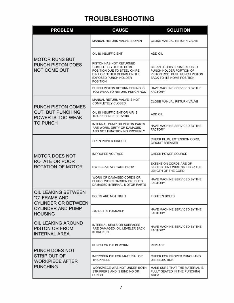
MELBORP ESUAC NOITULOS
TUBSNURROTOMSEODNOTSIPHCNUP
TUOEMOCTON
NEPOSIEVLAVNRUTERLAUNAM EVLAVNRUTERLAUNAMESOLC
TNEICIFFUSNISILIO LIODDA
DENRUTERTONSAHNOTSIPEMOHSTIOTYLETELPMOC
,SPIHCLEETSOTEUDNOITISOPEHTNOSIRBEDREHTOROTRID
REDLOH-HCNUPDESOPXE.NOITISOP
DESOPXEMORFSIRBEDNAELCFONOITROPREDLOH-HCNUP
NOTSIPHCNUPHSUP.DORNOTSIP.NOITISOPEMOHSTIOTKCAB
SIGNIRPSNRUTERNOTSIPHCNUPDORHCNUPNRUTEROTKAEWOOT
EHTYBDECIVRESENIHCAMEVAHYROTCAF
SEMOCNOTSIPHCNUPGNIHCNUPTUB,TUOKAEWOOTSIREWOP
HCNUPOT
TONSIEVLAVNRUTERLAUNAMDESOLCYLETELPMOC
EVLAVNRUTERLAUNAMESOLC
SIRIAROTNEICIFFUSNISILIORIOVRESERNIDEPPART
LIODDA
STRAPNOTSIPROPMUPLANRETNIDEGAMADROYTRID,NROWERAYLREPORPGNINOITCNUFTONDNA
EHTYBDECIVRESENIHCAMEVAHYROTCAF
TONSEODROTOMROOPROETATOR
ROTOMFONOITATOR
TIUCRICREWOPNEPO,DROCNOISNETXE,GULPKCEHC
REKAERBTIUCRIC
EGATLOVREPORPMI ECRUOSREWOPKCEHC
PORDEGATLOVEVISSECXEFOERASDROCNOISNETXE
EHTROFEZISERIWTNEICIFFUSNI.DROCEHTFOHTGNEL
ROSDROCDEGAMADRONROW.SEHSURBNOBRACNROW.SGULPSTRAPROTOMLANRETNIDEGAMAD
EHTYBDECIVRESENIHCAMEVAHYROTCAF
NEEWTEBGNIKAELLIODNAEMARF"C"
NEEWTEBROREDNILYCPMUPDNAREDNILYC
GNISUOH
THGITTONERASTLOB STLOBNETHGIT
DEGAMADSITEKSAGEHTYBDECIVRESENIHCAMEVAH
YROTCAF
DNUORAGNIKAELLIOMORFRONOTSIPAERALANRETNI
SECAFRUSROSLAESLANRETNIKCASRELEVELLIO.DEGAMADERA
NEKORBSI
EHTYBDECIVRESENIHCAMEVAHYROTCAF
TONSEODHCNUPFOTUOPIRTS
RETFAECEIPKROWGNIHCNUP
NROWSIEIDROHCNUP ECALPER
ROLAIRETAMROFEIDREPORPMISSENKCIHT
DNAHCNUPREPORPROFKCEHCNOITCELESEID
HTOBREDNUTONSAWECEIPKROWROGNIDNIBSIDNASREPPIRTS
HCNUP
SILAIRETAMEHTTAHTERUSEKAMGNIHCNUPEHTNIDETAESYLLUF
AERA
TROUBLESHOOTING
8

9
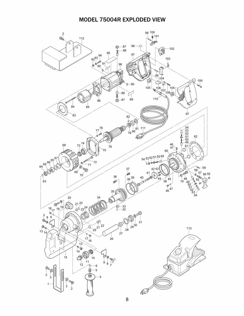
Det # Part # Description Qty
1 75358 HoleLocator 1
2 75156 SCR-SetScrew6X15mm 5
3 75157 FlatWasher 2
4 75063 PunchCarryHandle 1
5 75192 SCR-Set10X10mm 1
6 75191 SteelBall 1
7 75175 SCR-WingM6X15mm 1
8 75162 LockWasher 2
9 75119 Strippers 2
10 75908 O-Ring 1
11 75907 RetaingNut 1
13 75091 HexNutM6 2
14 75120 SCR-Set6X15mm 2
15 75121 “C”FRAME 1
16 75122 SetScrew6X6mm 2
17 75123 SteelBall 2
18 75236 SetScrew8X30mm 12
19 75159 Washer8mm 14
21 75124 BackUpRing 2
22 75909 O-Ring 2
23 75233 BackUpRing 1
24 75234 PackingRodSeal 1
25 75195 O-Ring 1
26 75137 OilBladder 1
27 75138 BladderScrew 1
28 75190 O-Ring 1
29 75188 BladderScrewBushing 1
30 75155 LockWasher10mm 1
31 75138 BladderRetainingScrew 1
32 75099 RollPin2.5X10mm 1
33 75135 PunchPistonKey 1
34 75196 PunchReturnSpring 1
35 75197 PunchPiston 1
36 75198 ValveSealNut 1
37 75199 ValveSealBolt 1
38 75200 O-Ring 2
39 75235 Packing 1
40 75201 SpoolReleaseValve 1
41 75202 ValveReturnSpring 1
42 75203 Stopper Plate 1
43 75204 ReleaseValveSpring 1
44 75205 ScrewSHC4X6mm 2
45 75206 BackUpRing 1
46 75207 SetScrew5X5mm 9
47 75208 SteelBall 9
48 75241 ScrewSHC8X25mm 2
49 75048A-JPumpPistonsarereplacedbysizeandfit.ThePump
CylinderwillneedtobereturnedtoHougenMfg.todeterminethecorrectpart.
50 75053 PistonReturnSpring 3
51 75050 CHECKVALVE 3
52 75052 CHECKVALVESPRING 3
53 75325 RubberPackingSeal 3
54 75326 O-Ring 3
55 75160 SetScrew6X8mm 2
56 75047 ReturnLever 1
57 75046 ReturnValve 1
58 75085 O-Ring 1
Det # Part # Description Qty
59 75209 RollPin 1
60 75255 PumpCylinder 1
61 75054 Magnet 3
62 75220 Gasket 1
63 75256 RetainingRing 1
64 75086 BallBearing 1
65 75055 Spacer 2
66 75088 RollerBearing 1
67 75257 RetainingRing 1
68 75258 PumpHousing 1
69 75090 SealWasher 1
70 75107 SCR-SHCM10X15MM 1
71 75872 Washer6mm 4
72 75871 ScrewSHC6X50mm 4
73 75259 OilSeal 1
74 75327 BallRing 1
75 75874 SubPlate 1
76 75821 Armature115v 1
77 75328 FlatWasher4mm 4
78 75826 ScrewSHC4X20mm 4
79 75822 PaperWasher 1
80 75823 BallRing 1
81 75824 ThrustWasher16mm 1
82 75825 RubberPin 1
83 75827 Fan Guide 1
84 75828 Screw5X65mm 2
85 75829 Field115v 1
86 75830 Field Support Set 1
87 75831 BrushCap 2
88 75832 CarbonBrush(pair) 1
89 75864 WarningTag 1
90 75834 AntiVibrationRubbers(B) 2
91 75865 CautionTag 1
92 75835 FlatWasher5mm 4
93 75836 LockWasher5mm 4
94 75837 ScrewSHC5X25mm 4
95 75329 NameTag 1
96 75838 MotorHousingSet 1
97 75839 HandleSet 1
98 75840 Label 1
99 75841 Pin3mm 2
100 75842 Compression Spring 1
101 75843 RockButton 1
102 75844 Switch 1
103 75845 Spacer 1
104 75846 SwitchLever 1
105 75850 AntiVibrationRubber(A) 4
106 75847 RunnerPlate 1
107 75848 Cord Clamp 1
108 75849 Screw4X18mm 2
109 75851 Screw4X25mm 5
110 75852 StrainRelief 1
111 75870 Power Cord 1
112 75330 Work Stand 1
113 75110 FootSwitch 1
75903 Pin Spanner 1
MODEL 75004R PARTS LIST
10
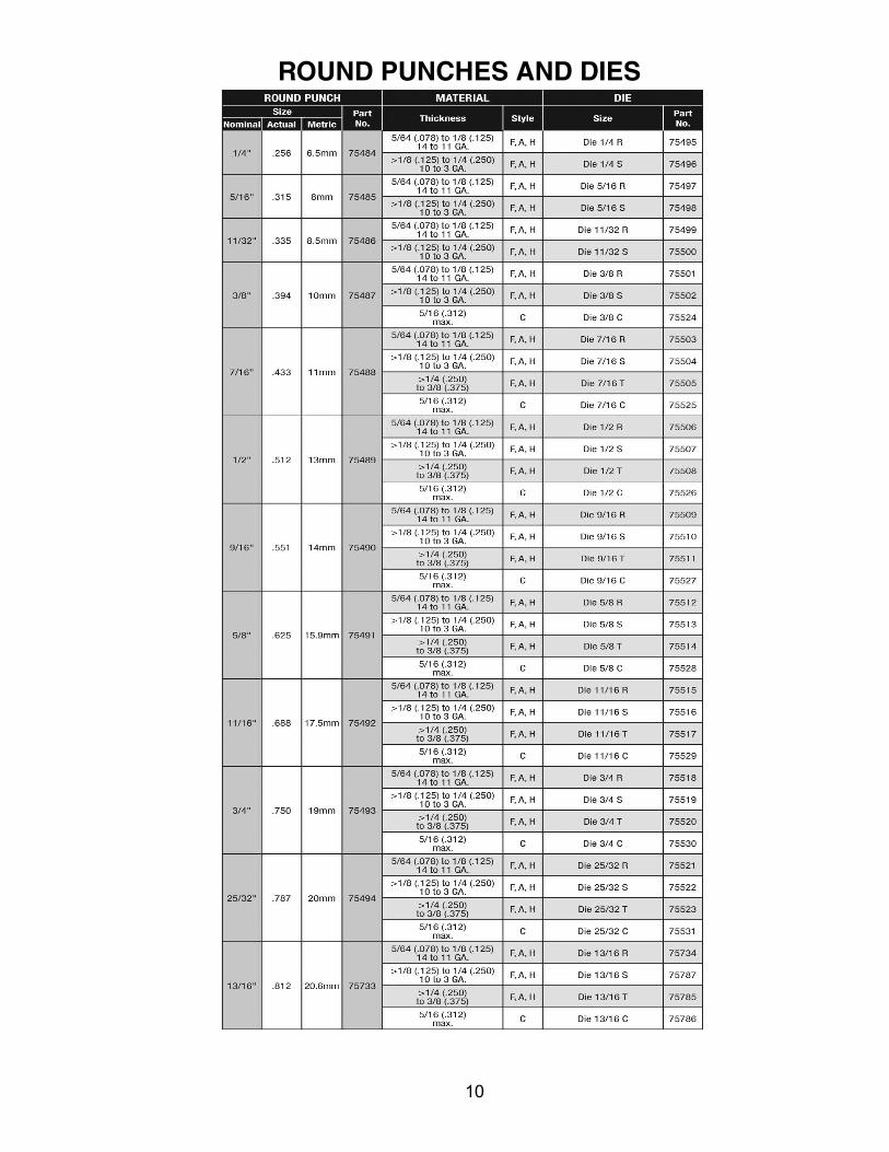
ROUND PUNCHES AND DIES
11
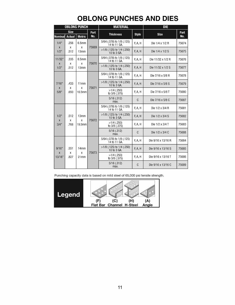
OBLONG PUNCHES AND DIES
HougenManufacturing,IncorporatedwarrantsitsPortableMagneticDrills,Electro-hydraulicHolePunchersforaperiodof(1)oneyearandotherproductsforninety(90)daysfromdateofpurchaseagainstdefectsduetofaultymaterialorworkmanshipandwillrepairorreplace(atitsoption)withoutchargeanyitemsreturned.Thiswarrantyisvoidiftheitemhasbeendamagedbyaccidentorunreasonableuse,neglect,improperservice,orothercausesnotarisingoutofdefectsinmaterialorworkmanship.Nootherexpressedwarrantyisgivenorauthorized.HougenManufacturing,Inc.disclaimsanyimpliedwarrantyofMERCHANTABILITYorFITNESSforanyperiodbeyondtheexpressedwarrantyandshallnotbeliableforincidentalorconsequentialdamages.Somestatesdonotallowexclusionsofincidentalorconsequentialdamagesorlimitationonhowlonganimpliedwarrantylastsand,ifthelawofsuchastategovernsyourpurchase,theaboveexclusionandlimitationmaynotapplytoyou.Thiswarrantygivesyouspecificlegalrightsandyoumayalsohaveotherrightswhichvaryfromstatetostate.
Toobtainwarrantyservice,returntheitem(s),transportationprepaid,toyournearestFactoryAuthorizedRepairCenterortoHougenManufacturing,Inc.,3001HougenDrive,SwartzCreek,Michigan48473. HougenDrills(RotabroachCutters)arewarrantedagainstmanufacturingdefectsonly.SubjecttoHougenManufacturing inspection.
THISWARRANTYISINLIEUOFANYOTHERWARRANTY,EXPRESSEDORIMPLIED,INCLUDINGANYWARRANTYOFMERCHANTABILITYORFITNESSFORAPARTICULARPURPOSE©2012HougenManufacturing,Inc.
PhotographsandSpecificationsshownareaccurateindetailattimeofprinting.Manufacturereservestherighttomakeimprovementsandmodificationswithoutpriornotice.Hougen,Hougen-Edge,Rotabroach,Punch-Pro,Trak-StarandtheHougenlogoareproprietarytrademarksofHougenManufacturing,Inc.OguraandOguralogoareproprietarytrademarksofOgura&Co.,Ltd.
HOUGEN - OGURA PATENT NOTICE
©2012HougenManufacturing,Inc.OM75004R1111 PrintedinU.S.A.
Commercial / Industrial Limited Warranty
HougenManufacturing,Inc.3001HougenDrive•SwartzCreek,MI48473Phone(810)635-7111•Fax(810)635-8277www.hougen.com • [email protected]
Factory Warranty Repair Servicescanbeobtainedbysendingyourproductto:
HougenManufacturing,Inc.3001HougenDrive
SwartzCreek,MI48473Attn:RepairDepartment


