15
OPERATOR’S MANUAL PORTABLE MAGNETIC DRILL FOR USE WITH HOUGEN “12,000-SERIES” CUTTERS HMD505 SERIES COVERS DRILL PART NUMBERS 0505102, 0505202 & 0505402

OPERATOR’S MANUAL
PORTABLE MAGNETIC DRILL
FOR USE WITH HOUGEN “12,000-SERIES” CUTTERS
HMD505 SERIES
COVERS DRILL PART NUMBERS 0505102, 0505202 & 0505402

2
Always wear eye protection while using cutting tools, or in the vicin-ity of cutting.
CAUTION! The slug is ejected at the end of the cut. Do not aim cutter or arbor so that ejected slug may hit someone around, or below you.
CAUTION! Cutters are sharp. Wear gloves when installing or removing cutter from arbor. Do not grab a rotating cutter.
CAUTION! To prevent electric shock, do not use power tools near wet areas, or where power tool may become wet.
SAFETY FIRST
HOUGEN® Portable Magnetic DrillModel HMD505
Welcome to HougenCongratulations on your purchase of the Hougen® Portable Magnetic Drill Model HMD505. Your model is designed to ® Portable Magnetic Drill Model HMD505. Your model is designed to ®
produce superior holes quickly and effi ciently. Through constant innovation and development, Hougen is committed to provide you with hole-producing tools and products to help you be more productive.
Before attempting to operate your new Portable Magnetic Drill, please read all instructions fi rst. These include the Operator’s Manual and Warning Label on the unit itself. With proper use, care, and maintenance, your model will provide you with years of effective hole drilling performance. Once again, thank you for selecting our product and welcome to Hougen.
Your new Hougen Magnet Base Drill now incorporates a Label for the Drill Part Number and Serial Number. Below gives an explanation of the Part Number and the location of the Label is shown on the Drill Breakdown Diagram.
INDEXImportant Safety Instructions 3-4Unpacking Drill, Cutter Installation 5 Installation of cutting fl uid bottle 6Operation of cutting fl uid bottle 6Magnet Operation, Operating instruction 6Hints for smoother operation, Maintenance 7HMD505 Exploded View 8Assembly Breakdowns 9-10
SAFETY FIRST
SAFETY FIRST
Cutter Type......................”12,000-Series”Hole Capacity...................7/16” to 2-3/8” 12mm to 51mm Depth of Cut..................... 3” 76mmMotor................................ 250/450 RPM, 14ANet Weight........................45 lbs. 20.3 kg
Specifi cations
Part No. Description
050510205052020505402
HMD505, 2 speed with coolant, 115 volt, plug “A” on page 3HMD505, 2 speed with coolant, 230 volt,plug “D” on page 3HMD505, 2 speed with coolant, 230 volt,plug “B” on page 3
Panel Hookup Diagram 11 120v Control Panel 12230v Control Panel 13Optional Coolant Bottle 14 Limited Warranty 14 “12,000-Series” Hougen Cutters 15Factory Service Centers 16
Panel Hookup Diagram 11
Limited Warranty 14
Factory Service Centers 16

1. Read All Instructions2. Grounding Instructions
This tool should be grounded while in use to protect the operator from electric shock. The tool is equipped with a 3-conductor cord and a 3-prong grounding type plug to fi t the proper grounding type receptacle. The green (or green and yellow) conductor in the cord is the grounding wire. Never connect the green (or green and yellow) wire to a live terminal. If your unit is for use on 115V, it has a plug that looks like that shown in sketch (A). If it is for use on 230V, it has a plug that looks like that shown in sketch (B). An adapter, see sketch and (C), is available for connecting sketch (A) type plugs to 2-prong receptacles. The green-colored rigid ear, lug, or the like, extending from the adapter must be connected to a permanent ground, such as a properly grounded outlet box. No adapter is available for a plug as shown in sketch (D).
3. Extension CordsUse only 3-wire extension cords that have 3-prong
grounding type plugs and 3-pole receptacles that accept the tool’s plug. Replace or repair damaged cords.
Make sure the conductor size is large enough to prevent excessive voltage drop which will cause loss of power and possible motor damage. See Table below.
3
4. Do Not Force Tool It will do the job better and faster at the rate for which it was intended.5. Keep Work Area Clean
Cluttered areas and benches invite injuries. Keep dirt and chips from under magnet and Hougen Cutter area.6. Consider Work Area Environment
Do not expose tool to rain. Do not use tool in damp or wet locations. Keep work area well lit. Do not use tool in presence of fl ammable liquids or gases.7. Guard Against Electric Shock
Prevent body contact with grounded surfaces. For example: pipes, radiators, ranges, refrigerator enclosures.8. Keep Children Away
Do not let visitors contact tool. All visitors should be kept away from work area.9. Store Idle Tools
When not in use, tools should be stored in a dry, and high or locked-up place — out of reach of children.10. Use Right Tool Do not force small tool or attachment to do the job of a heavy duty tool. Do not use tool for purpose not intended — for example — do not use a circular saw for cutting tree limbs or logs.11. Non-Conforming Cutting Tools Your Magnetic Drill is designed to use Hougen Cutters. The use of drilling tools having different shank styles is not recommended as they may not tighten securely in the drill arbor with risk of accident or injury.12. Secure Work Use clamps or a vise to hold work. It is safer than using your hand and it frees both hands to operate tool.13. Always Wear Safety Glasses or Goggles14. Dress Properly Do not wear loose clothing or jewelry. They might entangle with spinning chips or get caught in moving parts. Rubber gloves and nonskid footwear are recommended when working outdoors. Wear sturdy leather gloves when working indoors. Wear protective hair covering to contain long hair.15. Do Not Abuse Cord
Never carry drill unit by its cord or yank it to discon- nect from receptacle. Keep cord away from heat, oil, and sharp edges.16. Do Not Overreach
Keep proper footing and balance at all time.17. Maintain Tools With Care Keep tools sharp and clean for better and safer performance. Do not use dull or broken Hougen Cutters. Follow instructions for lubricating and changing accessories. Keep handles dry, clean, and free from oil and grease.
WARNING: When using electric tools, basic safety precautions should always be followed to reduce the risk of fi re, electric shock, and personal injury, including the following:
IMPORTANT SAFETY INSTRUCTIONS
,droCfohtgneLteeF
dednemmoceReguaGeriW
dednemmoceReguaGeriW
rotoMV511spmA41-01
rotoMV032spmA7-4
52otpU 61 81
05-62 41 81
001-15 01 61
002-101 8 41
003-102 6 21
005-103 4 01
Grounding Pin
Grounding Pin
GroundingMeans
(C)
(A) (B)
(D)
Panel Hookup Diagram 11 Use only 3-wire extension cords that have 3-prong
Panel Hookup Diagram 11 Use only 3-wire extension cords that have 3-prong
grounding type plugs and 3-pole receptacles that accept Panel Hookup Diagram 11 grounding type plugs and 3-pole receptacles that accept
Limited Warranty 14
4
Continued... Inspect tool cords periodically and, if damaged, have repaired by authorized service facility. Inspect extension cords periodically and, if damaged, have repaired by authorized service facility.18. Disconnect Tools Disconnect when not in use, before servicing, and when changing Hougen Cutters or accessories.19. Remove Adjusting Keys and Wrenches Form a habit of checking to see that keys and wrenches are removed from tool before turning it on.20. Check Damaged Parts Before further use of the drill, a part that is damaged should be carefully checked to determine that it will operate properly and perform its intended function. Check for alignment of moving parts, binding of moving parts, breakage of parts, mounting, and any other conditions that may affect its operation. A part that is damaged should be properly repaired or replaced by an authorized service center unless otherwise indicated elsewhere in this operator manual. Do not operate tool if switch does not turn it on and off.21. Stay Alert Watch what you are doing. Use common sense. Do not operate tool when you are tired.
Have defective switches replaced by authorized service center.22. Outdoor Use Extension Cords
When tool is used outdoors, use only extension cords intended for use outdoors and so marked.23. Additional Safety Precautions
Spindle and cutter should never be used as a hand- hold. Keep hands and clothing away from all moving parts. Do not use Hougen Cutters where ejected slug might cause injury (slug ejected at end of cut). Be sure that all safety devices are properly adjusted and in use. Also, adhere to all operating instructions. Do not drill through any surface that may contain live electrical wiring. Drilling into a live wire could cause exposed metal parts of the drill to be made live. Remove chips wrapped around Hougen Cutter and arbor after each hole. With motor off and power disconnected, grasp chips with leather gloved hand or pliers and pull while rotating counter- clockwise. Should the cutter become jammed in the work, stop the unit immediately to prevent personal injury. Disconnect the drill from the power supply and loosen jammed cutter by turning the arbor counterclockwise. Never attempt to free the jammed cutter by starting the motor. Service at authorized repair center only.24. Operating Near Welding Equipment It is NOT recommended that you use this tool on the same work surface as an arc welder. This can cause severe damage to the unit, particularly the power cord. This could also result in personal injury to the operator.
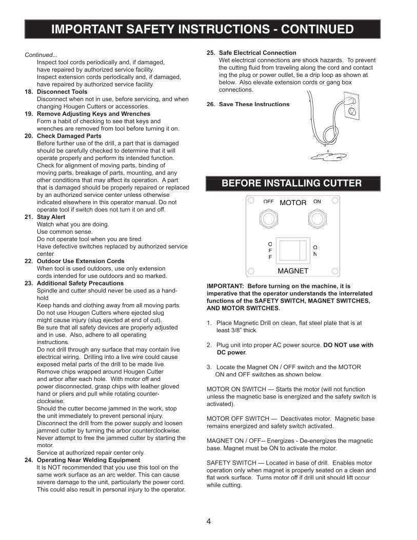
25. Safe Electrical ConnectionWet electrical connections are shock hazards. To prevent
the cutting fl uid from traveling along the cord and contact ing the plug or power outlet, tie a drip loop as shown at below. Also elevate extension cords or gang box connections.
26. Save These Instructions
IMPORTANT SAFETY INSTRUCTIONS - CONTINUED
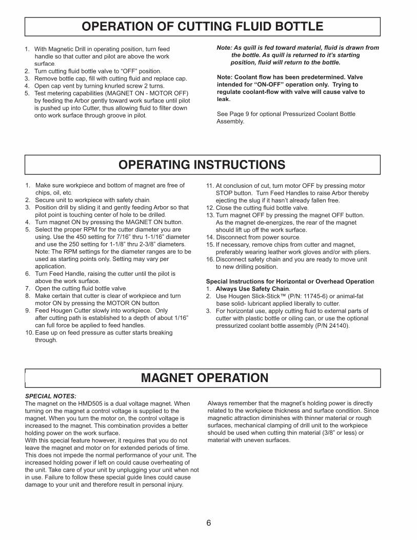
IMPORTANT: Before turning on the machine, it is imperative that the operator understands the interrelated functions of the SAFETY SWITCH, MAGNET SWITCHES, AND MOTOR SWITCHES.
1. Place Magnetic Drill on clean, fl at steel plate that is at least 3/8” thick.
2. Plug unit into proper AC power source. DO NOT use with DC power.
3. Locate the Magnet ON / OFF switch and the MOTOR ON and OFF switches as shown below.
MOTOR ON SWITCH — Starts the motor (will not function unless the magnetic base is energized and the safety switch is activated).
MOTOR OFF SWITCH — Deactivates motor. Magnetic base remains energized and safety switch activated.
MAGNET ON / OFF-- Energizes - De-energizes the magnetic base. Magnet must be ON to activate the motor.
SAFETY SWITCH — Located in base of drill. Enables motor operation only when magnet is properly seated on a clean and fl at work surface. Turns motor off if drill unit should lift occur while cutting.
MOTOR ONOFF
MAGNET
OFF
ON
BEFORE INSTALLING CUTTER

UNPACKING YOUR NEW MAGNETIC DRILL1. Open shipping carton and lay the drill case on it’s side.2. Open the case lid and remove the hardware and literature packets.3. Read and Follow All Instructions before attempting to operate your new Magnetic Drill.4. Complete and mail the Product Registration Card now. It is important that Hougen Manufacturing, Inc. have a record of product ownership.5. Included with your new Mag Drill are the following parts: 24011 Hub Assembly 01447 Feed Handles (3) 04532 Feed Handle Knobs (3) 10730 Safety Chain 11741 Concentrated Cutting Fluid (Pint) 24166 Hex-Key “T” Handle 7/32” 10727 Allen Wrench 3/16” 13013 Allen Wrench 5/32”
6. Using the handle of Magnetic Drill, lift unit out of the shipping case.7. Remove all packing and securing material from the drill unit.8. Your Magnetic Drill was factory adjusted prior to shipping. Check to make sure that all fasteners are snug and have not vibrated loose in transit.9. Your new Magnetic Drill comes complete with an internal quill/arbor assembly. The 3/4” diameter arbor bore fi ts all 3/4”- shank “12,000-Series” Hougen Cutters.
Reread Safety Warnings listed in the Operator’s Manual and on the drill unit to avoid injury. Follow operating procedures.
5
USE OF SAFETY CHAIN
The safety chain should be used to prevent the drill unit from falling in the event of a power failure or if the magnet breaks loose from the work surface. The safety chain should be attached to the drill by running it through the “D” ring located at the rear of the magnet, and tightly secured.
INSTALLATION OF CUTTING FLUID BOTTLE1. With Magnetic Drill in operating position, turn feed handle so that cutter and pilot are above the work surface.2. Set coolant bottle in carrying handle yoke with valve facing toward the spindle of the drill. Press down to seat nipple into port.3. Tighten mounting screw on back of coolant bottle.
4. To test cutting fl uid fl ow (with the magnet ON and motor OFF), feed the arbor gently toward the work surface until the pilot is pushed up into the cutter. Open valve on coolant bottle cap. Fluid should fi lter down onto the work surface through the groove in the pilot.5. To insure proper cutter lubrication, always make sure that the slot in the pilot is kept clean.
HOUGEN CUTTER INSTALLATION1. Disconnect from power source.2. Lay drill on its side with feed handles up or be sure Arbor clears table if unit is in normal operating position.3. Remove set screws from spindle.4. Insert proper pilot in shank end of Hougen Cutter. Pilot #24131 is recommended for use with spring loaded ejection on cutters 3/4” diameter and larger.
5. Insert Hougen Cutter until fl ats on cutter shank are aligned with set screw holes and are exactly perpendicular to axis of set screw holes. If 1/2” diameter shank cutter is used, slip (10851) Arbor Adapter over the cutter shank with adapter hole positioned exactly over fl at on cutter shank prior to inserting into Arbor bore.6. Insert set screws and tighten. Check to be certain that cutter is secure.
6
1. With Magnetic Drill in operating position, turn feed handle so that cutter and pilot are above the work surface.2. Turn cutting fl uid bottle valve to “OFF” position.3. Remove bottle cap, fi ll with cutting fl uid and replace cap.4. Open cap vent by turning knurled screw 2 turns.5. Test metering capabilities (MAGNET ON - MOTOR OFF) by feeding the Arbor gently toward work surface until pilot is pushed up into Cutter, thus allowing fl uid to fi lter down onto work surface through groove in pilot.
OPERATION OF CUTTING FLUID BOTTLE
Note: As quill is fed toward material, fl uid is drawn from the bottle. As quill is returned to it’s starting position, fl uid will return to the bottle.
Note: Coolant fl ow has been predetermined. Valve intended for “ON-OFF” operation only. Trying to regulate coolant-fl ow with valve will cause valve to leak. See Page 9 for optional Pressurized Coolant Bottle Assembly.
OPERATING INSTRUCTIONS
1. Make sure workpiece and bottom of magnet are free of chips, oil, etc.2. Secure unit to workpiece with safety chain.3. Position drill by sliding it and gently feeding Arbor so that pilot point is touching center of hole to be drilled.4. Turn magnet ON by pressing the MAGNET ON button.5. Select the proper RPM for the cutter diameter you are using. Use the 450 setting for 7/16” thru 1-1/16” diameter and use the 250 setting for 1-1/8” thru 2-3/8” diameters. Note: The RPM settings for the diameter ranges are to be used as starting points only. Setting may vary per application.6. Turn Feed Handle, raising the cutter until the pilot is above the work surface. 7. Open the cutting fl uid bottle valve.8. Make certain that cutter is clear of workpiece and turn motor ON by pressing the MOTOR ON button.9. Feed Hougen Cutter slowly into workpiece. Only after cutting path is established to a depth of about 1/16” can full force be applied to feed handles.10. Ease up on feed pressure as cutter starts breaking through.
11. At conclusion of cut, turn motor OFF by pressing motor STOP button. Turn Feed Handles to raise Arbor thereby ejecting the slug if it hasn’t already fallen free.12. Close the cutting fl uid bottle valve.13. Turn magnet OFF by pressing the magnet OFF button. As the magnet de-energizes, the rear of the magnet should lift up off the work surface.14. Disconnect from power source.15. If necessary, remove chips from cutter and magnet, preferably wearing leather work gloves and/or with pliers.16. Disconnect safety chain and you are ready to move unit to new drilling position.
Special Instructions for Horizontal or Overhead Operation1. Always Use Safety Chain.2. Use Hougen Slick-Stick™ (P/N: 11745-6) or animal-fat base solid- lubricant applied liberally to cutter.3. For horizontal use, apply cutting fl uid to external parts of cutter with plastic bottle or oiling can, or use the optional pressurized coolant bottle assembly (P/N 24140).
MAGNET OPERATIONSPECIAL NOTES:The magnet on the HMD505 is a dual voltage magnet. When turning on the magnet a control voltage is supplied to themagnet. When you turn the motor on, the control voltage is increased to the magnet. This combination provides a betterholding power on the work surface. With this special feature however, it requires that you do not leave the magnet and motor on for extended periods of time. This does not impede the normal performance of your unit. The increased holding power if left on could cause overheating of the unit. Take care of your unit by unplugging your unit when not in use. Failure to follow these special guide lines could cause damage to your unit and therefore result in personal injury.
Always remember that the magnet’s holding power is directly related to the workpiece thickness and surface condition. Since magnetic attraction diminishes with thinner material or rough surfaces, mechanical clamping of drill unit to the workpiece should be used when cutting thin material (3/8” or less) or material with uneven surfaces.
MAGNET OPERATION

7
HINTS FOR SMOOTHER OPERATION1. Keep insides of Hougen Cutter clear of chips. Chips will interfere with cutting to maximum depth as well as impede free oil fl ow from arbor to work and can cause cutter breakage.2. Keep workpiece, machine, arbor and Hougen Cutter free of chips and dirt.3. Tighten all bolts regularly.4. We highly recommend using a light viscosity cutting fl uid (preferably RotaMagic™ Cutting Fluid - P/N: 11742-4).5. Occasionally check metering of cutting fl uid fl ow. Lack of coolant may cause Hougen Cutter to freeze in cut, slug to stick, and may result in poor cutter life.6. Always start cut with light feed pressure and then increase suffi ciently to achieve maximum cutting rate.7. Ease off on pressure as cutter begins to break through at end of cut.8. Keep magnet and cutter free of chips and dirt.9. if slug hangs up in cutter, turn motor off and bring cutter down on fl at surface. This will normally straighten a cocked slug, allowing it to be ejected.
10. Cut overlapping holes as illustrated, using minimum steady pressure. When cutter is removing material whose cross- section is half or less than the cutter diameter, pilot should be removed and tool should be fed with care. External lubrication should be used.
NOTE: When cutting in this manner, cutting fl uid may escape from the cutting area. Tool should be fed with care, using external lubrication.
11. When cutting large diameter or deep holes, it may be necessary to stop in the middle of the cut to add cutting fl uid to the reservoir and also remove chips from around the arbor. When doing this, do not raise the cutter out of the hole. Doing so can allow chips to get under the teeth of the cutter and make it diffi cult to restart the cut.
#1 cause of cutter breakage and
prematurely dull teeth is too little feed pressure.
MAINTENANCEIn order to minimize wear on moving parts and to insure smoother operation and longer life for your magnetic drill, the following maintenance should be done periodically, based on use.1. Regularly tighten all fasteners and replace any worn components.
2. Check motor brushes and replace if worn.3. Check power cord and motor cord. If cracked or frayed, return to authorized repair center for replacement.
2. Check motor brushes and replace if worn.
“Babying” the Cutter through the cut will only decrease tool life.
450 RPM 250 RPM 7/16” - 1-1/16” Diameters 1-1/8” - 2-3/8” Diameters 12mm - 27mm Diameters 28mm - 60mm Diameters
450 RPM 250 RPM 12mm - 27mm Diameters 28mm - 60mm Diameters
RECOMMENDED RPM’S
8
HOUGEN HMD505 EXPLODED VIEW
16
�
�
8
9
19
20
2
�
7
��
1213
14
10
15
�����
18
21,30
22,28
23
24
25
26
27
1
62
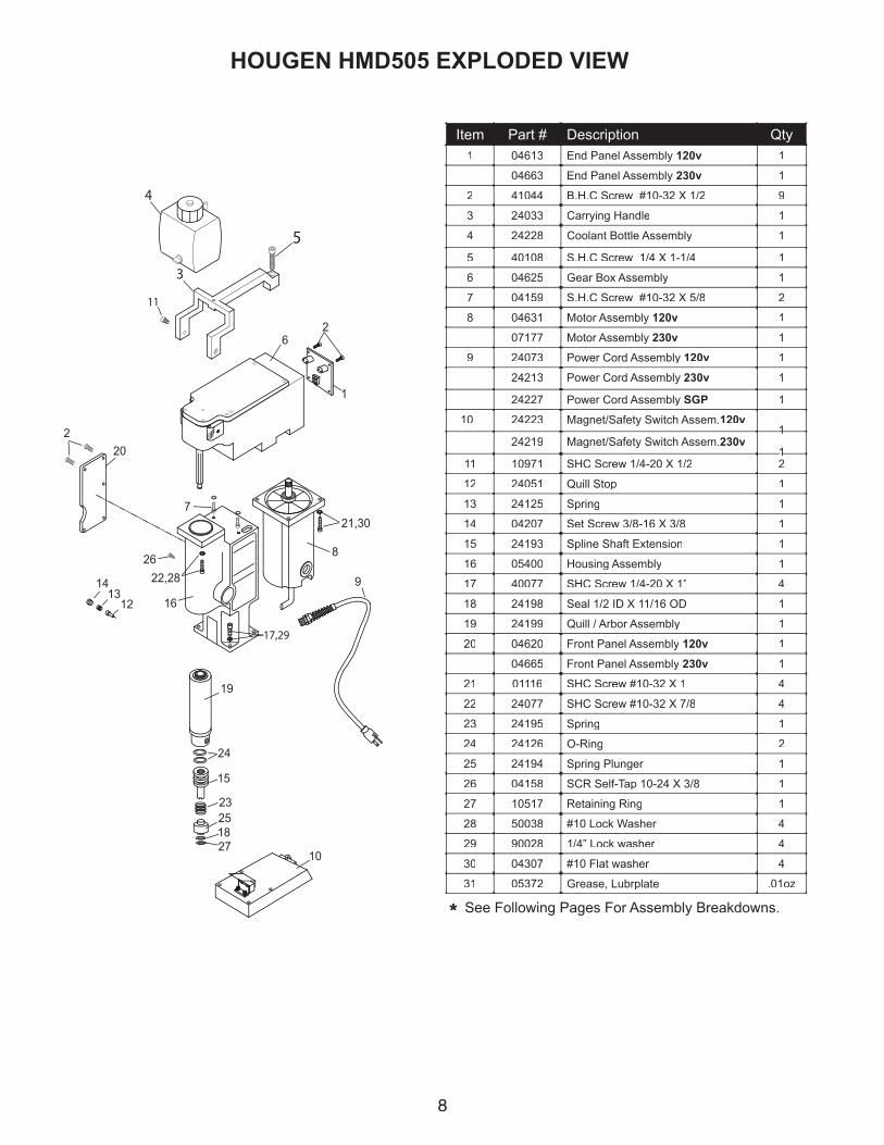
Item Part # Description Qty1 04613 End Panel Assembly 120v 1
04663 End Panel Assembly 230v 1
2 41044 B.H.C Screw #10-32 X 1/2 9
3 24033 Carrying Handle 1
4 24228 Coolant Bottle Assembly 1
5 40108 S.H.C Screw 1/4 X 1-1/4 1
6 04625 Gear Box Assembly 1
7 04159 S.H.C Screw #10-32 X 5/8 2
8 04631 Motor Assembly 120v 1
07177 Motor Assembly 230v 1
9 24073 Power Cord Assembly 120v 1
24213 Power Cord Assembly 230v 1
24227 Power Cord Assembly SGP 1
10 24223 Magnet/Safety Switch Assem.120v 11
24219 Magnet/Safety Switch Assem.230v 11
11 10971 SHC Screw 1/4-20 X 1/2 2
12 24051 Quill Stop 1
13 24125 Spring 1
14 04207 Set Screw 3/8-16 X 3/8 1
15 24193 Spline Shaft Extension 1
16 05400 Housing Assembly 1
17 40077 SHC Screw 1/4-20 X 1” 4
18 24198 Seal 1/2 ID X 11/16 OD 1
19 24199 Quill / Arbor Assembly 1
20 04620 Front Panel Assembly 120v 1
04665 Front Panel Assembly 230v 1
21 01116 SHC Screw #10-32 X 1 4
22 24077 SHC Screw #10-32 X 7/8 4
23 24195 Spring 1
24 24126 O-Ring 2
25 24194 Spring Plunger 1
26 04158 SCR Self-Tap 10-24 X 3/8 1
27 10517 Retaining Ring 1
28 50038 #10 Lock Washer 4
29 90028 1/4” Lock washer 4
30 04307 #10 Flat washer 4
31 05372 Grease, Lubrplate .01oz
* See Following Pages For Assembly Breakdowns.

9
2
3
1
7
8
910
10a
456
11
12
13
1415
16
18
19
10c
10b
23
17
20
22
04625 Gear Box AssemblyItem Part # Description Qty
1 24229 Gear Shift Handle 1
2 24046 Gear Switch Plate 1
3 24038 Gear Shift Pin 1
4 24039 Gear Shift Yoke 1
5 24037 Dowel Pin 3/16 X 1-1/4 1
6 24036 Gear Shift Spacer 2
7 24101 SHSLD Screw 1/4 X 3/8 1
8 04157 FHSC Screw #10-32 X 3/8 4
9 05740 Spring 1
10 04640 Gear Box Assembly (includes a-c) 1
10a 24096 Lip Seal 1
10b 05181 Hougen Label 1
10c 24060 Drill Speed Label 1
11 24027 Gear & Shaft Assembly 1
12 24026 Gear 32/39 Tooth 1
13 24105 Gear & Shaft Assembly 15/20 Tooth 1
14 24104 Gear & Shaft Assembly 14 Tooth 1
15 24103 Gear & Shaft Assembly 15 Tooth 1
16 24102 Spline Shaft Assembly 1
17 04623 Cover & Bearing Assembly 1
18 24030 Key 3/16 sq. X 1.70 1
19 24082 SHC Screw 6-32 X 3/8 3
20 40038 SHC Screw 10-32 X 5/8 6
21 24152 Grease Lubriplate GR132
22 24095 Lip Seal 1
23 24100 Ball Bearing 4
24223 120v Magnet Assembly24219 230v Magnet Assembly
Item Part # Description Qty
1 24222 Magnet Assembly 120v 1
24220 Magnet Assembly 230v 1
2 10990 Safety Switch Assy. 1
3 24221 Plunger Assembly 1
4 04909 Safety Switch Bracket 1
5 10983 Shield 1
6 10971 Screw SHC 1/4-20 X 1/2 2
7 10972 Screw BHC 6-32 X 7/8 2
8 17271 Spring 1
9 41046 Screw SHC 10-32 X 1/2 2
10 24144 “D” Ring 1” Wide 1
11 04698 Plate - Chain Hold down 1
1 (120v) (230v)
2
34
5
6
7
8
9
10
11
***
*
*These Parts Are Included In Kit 24230.

10
�
�
�
�
�
��
�
24199 Arbor / Quill AssemblyItem Part # Description Qty
1 40222 Set Screw 7/16-14 X .305 2
2 24013 Thrust Bearing Seal 1
3 24094 Thrust Bearing 1
4 24091 Thrust Washer 1
5 24016 Quill 1
6 24165 Washer 1
7 24164 Retaining Ring 1
04631 120v Motor Assembly07177 230v Motor Assembly
Item Part # Description Qty
1 04633 Motor Housing Assy. 120v 1
1a 04632 HMD505 Label 1
1b 04634 Motor Specs Label 120v 1
2 07178 Motor Housing Assy. 230v 1
2a 04632 HMD505 Label 1
2b 07154 Motor Specs Label 230v 1
3 24114 Motor Baffl e 1
4 24066 Access Door 1
5 24041 Armature 120v 1
24207 Armature 230v 1
6 24042 Field Assembly 120v 1
24206 Field Assembly 230v 1
7 40373 Strain Relief 2
8 24045 Carbon Brushes 120v/230v 2
9 24044 Brush Cap 2
10 24080 Screw #10 X 3-1/4 Self Tapping 2
11 24153 Screw #10 X 1/2 Self Tapping 2
12 90019 16-14 Connector 2
13 24093 Spring Washer 1
* INCLUDES MOTOR CORD
1 (120v)
2 (230v)
3
4
5
* 6
7
8
9
10
11
12
13

11
HMD505 HOOK UP DIAGRAM
WH
ITE
MO
TO
RW
IRE
BLA
CK
SA
FE
TY
SW
ITC
H W
IRE
TO
YE
LLO
WM
AG
NE
T W
IRE BLA
CK
MO
TO
R
WIR
E
WH
ITE
SA
FE
TY
SW
ITC
H W
IRE
EN
D P
AN
EL
AS
SY.
CA
VIT
Y
5
5
2
14
4
0468
9 W
IRE
HA
RN
ES
S
0464
7 W
IRE
HA
RN
ES
S04
647
WIR
E H
AR
NE
SS
0468
9 W
IRE
HA
RN
ES
S
6
6
3
3
2
1
0467
8
9002
0
9021
8
0368
8
0141
4
0133
901
414
0133
9

12
120v HMD505 PANEL PARTS
Part # Description Qty
01310 Terminal Piggy Back 2
01496 Spacer 2
01547 Terminal Strip 1
01835 Nylon Nut 5
01944 Terminal Jumper 1
01945 Terminal Spade 3
02916 Capacitor 1
03688 Terminal Male Insulator 2
04387 Relay 240V 1
04614 Rocker Switch 1
04615 Faceplate End 1
04621 Faceplate Front 1
04622 Double Terminal 3
04643 Red Seal 1
Part # Description Qty
04644 Green Seal 1
04645 Switch On 1
04646 Switch Off 1
04678 Terminal Female Insulator 1
04690 Relay 15A 1
10705 Rectifi er 1
10718 Surge Suppressor 1
24141 Circuit Breaker 14A 1
24142 Cover 1
40296 Sponge Seal 1
51038 Flat Washer #6 2
90036 Adhesive 1
90090 Terminal Piggy Back 1
90218 Terminal Female 1
1 2
3 4
5 6
A B
90090
0462104622
04387
40296
01835 51038
01945
04622
03688
24142
24141
01945
01944
01547
01496
9021804678
03688
90036
0469001835
01835
10705
10718
02916
0461540296
04645 04644
04614
04646 04643
01310
01310
~
~
~
~
3
4
1 2
1 2
3 4
5 6
A B
PANEL ASSEMBLY END (04613)
PANEL ASSEMBLYMAIN (04620)

13
HMD5 230v HMD505 PANEL PARTS
01496
01547
0194401945
04622
0183551038
40296
10760
90019
0464404645
04615 40296
0464304646
04664
24216
24142
10705
04387
~
~
PANEL ASSY END 04663
MAIN PANEL ASSY 04665
90090
04621
Part # Description Qty
01496 Spacer 2
01547 Term Strip 1
01835 Nylon Nut 2
01944 Jumper Terminal 1
01945 Spade Terminal 3
04387 Relay 240VAC 1
04615 Faceplate End 1
04621 Faceplate Front 1
04622 Double Terminal 3
04643 Seal Red 1
04644 Seal Green 1
04645 Switch - ON 1
04646 Switch - OFF 1
Part # Description Qty
04647 Wire Assy 1
04648 Wire Assy 1
04663 Panel Assy End 1
04664 Rocker Switch 1
04665 Panel Assy Main 1
10705 Rectifi er 1
10760 Surge Suppressor 1
24142 Cover Splash 1
24216 Circuit Breaker 7 Amp 1
40296 Seal 2 ft
51038 Flat Washer 2
90019 Terminal Female 3
90020 Terminal Male 4
OPTIONAL PRESSURIZED COOLANT BOTTLE
�
���
� �
�
������
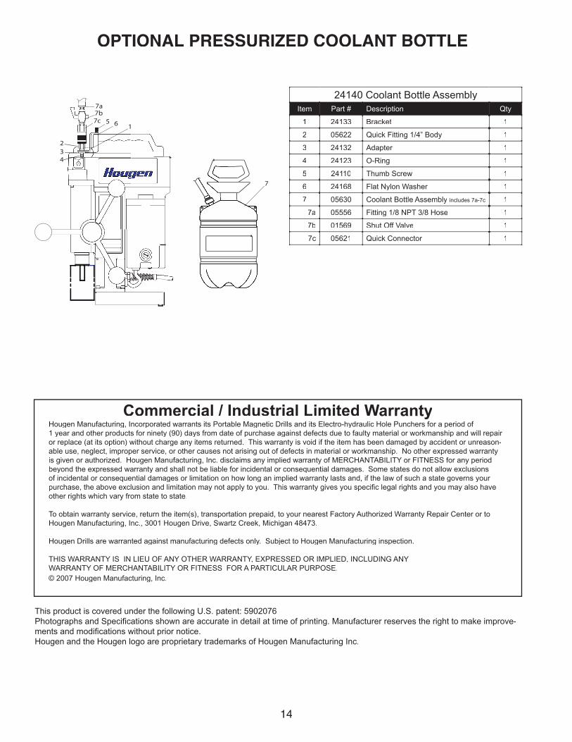
24140 Coolant Bottle AssemblyItem Part # Description Qty
1 24133 Bracket 1
2 05622 Quick Fitting 1/4” Body 1
3 24132 Adapter 1
4 24123 O-Ring 1
5 24110 Thumb Screw 1
6 24168 Flat Nylon Washer 1
7 05630 Coolant Bottle Assembly includes 7a-7c 1
7a 05556 Fitting 1/8 NPT 3/8 Hose 1
7b 01569 Shut Off Valve 1
7c 05621 Quick Connector 1
Hougen Manufacturing, Incorporated warrants its Portable Magnetic Drills and its Electro-hydraulic Hole Punchers for a period of 1 year and other products for ninety (90) days from date of purchase against defects due to faulty material or workmanship and will repair or replace (at its option) without charge any items returned. This warranty is void if the item has been damaged by accident or unreason-able use, neglect, improper service, or other causes not arising out of defects in material or workmanship. No other expressed warranty is given or authorized. Hougen Manufacturing, Inc. disclaims any implied warranty of MERCHANTABILITY or FITNESS for any period beyond the expressed warranty and shall not be liable for incidental or consequential damages. Some states do not allow exclusions of incidental or consequential damages or limitation on how long an implied warranty lasts and, if the law of such a state governs your purchase, the above exclusion and limitation may not apply to you. This warranty gives you specifi c legal rights and you may also have other rights which vary from state to state.
To obtain warranty service, return the item(s), transportation prepaid, to your nearest Factory Authorized Warranty Repair Center or to Hougen Manufacturing, Inc., 3001 Hougen Drive, Swartz Creek, Michigan 48473.
Hougen Drills are warranted against manufacturing defects only. Subject to Hougen Manufacturing inspection.
THIS WARRANTY IS IN LIEU OF ANY OTHER WARRANTY, EXPRESSED OR IMPLIED, INCLUDING ANY WARRANTY OF MERCHANTABILITY OR FITNESS FOR A PARTICULAR PURPOSE.© 2007 Hougen Manufacturing, Inc.
Commercial / Industrial Limited Warranty
This product is covered under the following U.S. patent: 5902076Photographs and Specifi cations shown are accurate in detail at time of printing. Manufacturer reserves the right to make improve-ments and modifi cations without prior notice. Hougen and the Hougen logo are proprietary trademarks of Hougen Manufacturing Inc.
14

15
“12,000-SERIES” HOUGEN CUTTERSCutter Dia.(Inches)
DecimalEquivalentEquivalentEquiv
Part Part P No.1” D.OD.OD. .C.O.C.O 2” D.OD.OD. .C.O.C.O 3” D.OD.OD. .C.O.C.O
Use with Pilot 10531 10532 7/16 .4375 12114 12214 ----
Use with Pilot 10533 105341/2 .5000 12116 12216 ----
9/16 .5625 12118 12218 ---- 5/8 .6250 12120 12220 ----
11/16 .6875 12122 12222 ---- Use with Pilot 10527 10528 24131
3/4 .7500 12124 12224 3-1222413/16 .8125 12126 12226 3-122267/8 .8750 12128 12228 3-12228
15/16 .9375 12130 12230 3-122301 1.0000 12132 12232 3-12232
1-1/16 1.0625 12134 12234 3-122341-1/8 1.1250 12136 12236 3-12236
1-3/16 1.1875 12138 12238 3-122381-1/4 1.2500 12140 12240 3-12240
1-5/16 1.3125 12142 12242 3-122421-3/8 1.3750 12144 12244 3-12244
1-7/16 1.4375 12146 12246 3-122461-1/2 1.5000 12148 12248 3-12248
1-9/16 1.5625 12150 12250 3-122501-5/8 1.6250 12152 12252 3-12252
1-11/16 1.6875 12154 12254 3-122541-3/4 1.7500 12156 12256 3-12256
1-13/16 1.8125 12158 12258 3-122581-7/8 1.8750 12160 12260 3-12260
1-15/16 1.9375 12162 12262 3-122622 2.0000 12164 12264 3-12264
2-1/16 2.0625 ---- 12266 ----2-1/8 2.1250 ---- 12268 ----
2-3/16 2.1875 ---- 12270 ----2-1/4 2.2500 ---- 12272 ----
2-5/16 2.3125 ---- 12274 ----2-3/8 2.3750 ---- 12276 ----
Cutter Dia.(Metric)
DecimalEquivalentEquivalentEquiv
Part Part P No.1” D.OD.OD. .C.O.C.O 2” D.OD.OD. .C.O.C.O 3” D.OD.OD. .C.O.C.O
Use with Pilot 10531 1053212mm .4724 12312 12412 ----
Use with Pilot 10533 1053413mm .5118 12313 12413 ----14mm .5512 12314 12414 ----15mm .5906 12315 12415 ----16mm .6299 12316 12416 ----17mm .6693 12317 12417 ----18mm .7087 12318 12418 ----
Use with Pilot 10527 10528 2413119mm .7480 12319 12419 1251920mm .7874 12320 12420 1252021mm .8268 12321 12421 1252122mm .8661 12322 12422 1252223mm .9055 12323 12423 1252324mm .9449 12324 12424 1252425mm .9843 12325 12425 1252526mm 1.0236 12326 12426 1252627mm 1.0630 12327 12427 1252728mm 1.1024 12328 12428 1252829mm 1.1417 12329 12429 1252930mm 1.1811 12330 12430 1253031mm 1.2205 12331 12431 1253132mm 1.2598 12332 12432 1253233mm 1.2992 12333 12433 1253334mm 1.3386 12334 12434 1253435mm 1.3779 12335 12435 1253536mm 1.4173 12336 12436 1253637mm 1.4567 12337 12437 1253738mm 1.4961 12338 12438 1253839mm 1.5354 12339 12439 1253940mm 1.5743 12340 12440 1254041mm 1.6142 12341 12441 1254142mm 1.6535 12342 12442 1254243mm 1.6929 12343 12443 1254344mm 1.7323 12344 12444 1254445mm 1.7717 12345 12445 1254546mm 1.8110 12346 12446 1254647mm 1.8504 12347 12447 1254748mm 1.8898 12348 12448 1254849mm 1.9291 12349 12449 1254950mm 1.9685 12350 12450 1255051mm 2.0079 12351 12451 12551 52mm 2.0472 12352 12452 12552


