This document supports software version 2.0 and above. Warning The servicing instructions are for use by qualified personnel only. To avoid personal injury, do not perform any servicing unless you are qualified to do so. Refer to all safety summaries prior to performing service. Service Manual 764 Digital Audio Monitor (Serial Number B020000 and Above) 070-8810-05
Transcript
This document supports software version 2.0and above.
WarningThe servicing instructions are for use by qualifiedpersonnel only. To avoid personal injury, do notperform any servicing unless you are qualified todo so. Refer to all safety summaries prior toperforming service.
Service Manual
764 Digital Audio Monitor(Serial Number B020000 and Above)
070-8810-05
Copyright Tektronix, Inc. All rights reserved.
Tektronix products are covered by U.S. and foreign patents, issued and pending. Information in this publication supercedesthat in all previously published material. Specifications and price change privileges reserved.
Printed in the U.S.A.
Tektronix, Inc., P.O. Box 1000, Wilsonville, OR 97070–1000
TEKTRONIX and TEK are registered trademarks of Tektronix, Inc.
Microsoft is a registered trademark and Windows is a trademark of Microsoft Corporation. PROCOMM is aregistered trademark of Datastorm Technologies, Inc.
For product related information, phone 800–TEKWIDE (800–835–9433), extension TV, toll free.
WARRANTY
Tektronix warrants that the products that it manufactures and sells will be free from defects in materials and workmanshipfor a period of one (1) year from the date of shipment. If a product proves defective during this warranty period, Tektronix,at its option, either will repair the defective product without charge for parts and labor, or will provide a replacement inexchange for the defective product.
In order to obtain service under this warranty, Customer must notify Tektronix of the defect before the expiration of thewarranty period and make suitable arrangements for the performance of service. Customer shall be responsible forpackaging and shipping the defective product to the service center designated by Tektronix, with shipping charges prepaid.Tektronix shall pay for the return of the product to Customer if the shipment is to a location within the country in which theTektronix service center is located. Customer shall be responsible for paying all shipping charges, duties, taxes, and anyother charges for products returned to any other locations.
This warranty shall not apply to any defect, failure or damage caused by improper use or improper or inadequatemaintenance and care. Tektronix shall not be obligated to furnish service under this warranty a) to repair damage resultingfrom attempts by personnel other than Tektronix representatives to install, repair or service the product; b) to repairdamage resulting from improper use or connection to incompatible equipment; c) to repair any damage or malfunctioncaused by the use of non-Tektronix supplies; or d) to service a product that has been modified or integrated with otherproducts when the effect of such modification or integration increases the time or difficulty of servicing the product.
THIS WARRANTY IS GIVEN BY TEKTRONIX IN LIEU OF ANY OTHER WARRANTIES, EXPRESS ORIMPLIED. TEKTRONIX AND ITS VENDORS DISCLAIM ANY IMPLIED WARRANTIES OFMERCHANTABILITY OR FITNESS FOR A PARTICULAR PURPOSE. TEKTRONIX’ RESPONSIBILITY TOREPAIR OR REPLACE DEFECTIVE PRODUCTS IS THE SOLE AND EXCLUSIVE REMEDY PROVIDED TOTHE CUSTOMER FOR BREACH OF THIS WARRANTY. TEKTRONIX AND ITS VENDORS WILL NOT BELIABLE FOR ANY INDIRECT, SPECIAL, INCIDENTAL, OR CONSEQUENTIAL DAMAGES IRRESPECTIVEOF WHETHER TEKTRONIX OR THE VENDOR HAS ADVANCE NOTICE OF THE POSSIBILITY OF SUCHDAMAGES.
EC Declaration of Conformity
We
Tektronix Holland N.V.Marktweg 73A8444 AB HeerenveenThe Netherlands
declare under sole responsibility that the
764 Digital Audio Monitor
meets the intent of Directive 89/336/EEC for Electromagnetic Compatibility and LowVoltage Directive 73/23/ECC for Product Safety. Compliance was demonstrated to thefollowing specifications as listed in the Official Journal of the European Communities:
EMC Directive 89/336/EEC:
EN 50081-1 Emissions:
EN 55022 Class B Radiated and Conducted Emissions
EN 50082-1 Immunity:
IEC 801-2 Electrostatic Discharge ImmunityIEC 801-3 RF Electromagnetic Field ImmunityIEC 801-4 Electrical Fast Transient/Burst Immunity
Low Voltage Directive 73/23/EEC:
EN 61010-1 Safety requirements for electrical equipment for measurement, control, and laboratory use
High-quality shielded cables must be used to ensure compliance to the above listedstandards.
This product complies when installed into any of the following Tektronix instrumentenclosures:
1700F00, Standard Cabinet bearing part number 437-0100-041700F02, Portable Cabinet bearing part number 390-0018-071700F05, Rack Adapter bearing part number 437-0095-04
Review the following safety precautions to avoid injury and prevent damage tothis product or any products connected to it.
Only qualified personnel should perform service procedures.
Use Proper Power Cord. Use only the power cord specified for this product andcertified for the country of use.
Use Proper Power Source. Do not operate this product from a power source thatapplies more than the voltage specified.
Ground the Product. This product is grounded through the grounding conductorof the power cord. To avoid electric shock, the grounding conductor must beconnected to earth ground. Before making connections to the input or outputterminals of the product, ensure that the product is properly grounded.
Observe All Terminal Ratings. To avoid fire or shock hazard, observe all ratingsand markings on the product. Consult the product manual for further ratingsinformation before making connections to the product.
Use Proper Fuse. To avoid fire hazard, use only the fuse type and rating specifiedfor this product.
Do Not Operate Without Covers. Do not operate this product with covers or panelsremoved.
Provide Proper Ventilation. To prevent product overheating, provide properventilation.
Do Not Operate With Suspected Failures. If you suspect there is damage to thisproduct, have it inspected by qualified service personnel.
Do Not Operate in Wet/Damp Conditions.
Do Not Operate in an Explosive Atmosphere.
To Avoid Fire or Personal Injury
General Safety Summary
viii 764 Digital Audio Monitor Service Manual
Terms in this Manual. These terms may appear in this manual:
WARNING. Warning statements identify conditions or practices that could resultin injury or loss of life.
CAUTION. Caution statements identify conditions or practices that could result indamage to this product or other property.
Terms on the Product. These terms may appear on the product:
DANGER indicates an injury hazard immediately accessible as you read themarking.
WARNING indicates an injury hazard not immediately accessible as you read themarking.
CAUTION indicates a hazard to property including the product.
Symbols on the Product. The following symbols may appear on the product:
Protective Ground(Earth) Terminal
ATTENTIONRefer to Manual
Double Insulated
DANGERHigh Voltage
Symbols and Terms
764 Digital Audio Monitor Service Manual ix
Service Safety Summary
Only qualified personnel should perform service procedures. Read this ServiceSafety Summary and the General Safety Summary before performing any serviceprocedures.
Do Not Service Alone. Do not perform internal service or adjustments of thisproduct unless another person capable of rendering first aid and resuscitation ispresent.
Disconnect Power. To avoid electric shock, disconnect the main power by meansof the power cord or, if provided, the power switch.
Use Caution When Servicing the CRT. To avoid electric shock or injury, useextreme caution when handling the CRT. Only qualified personnel familiar withCRT servicing procedures and precautions should remove or install the CRT.
CRTs retain hazardous voltages for long periods of time after power is turned off.Before attempting any servicing, discharge the CRT by shorting the anode tochassis ground. When discharging the CRT, connect the discharge path to groundand then the anode. Rough handling may cause the CRT to implode. Do not nickor scratch the glass or subject it to undue pressure when removing or installing it.When handling the CRT, wear safety goggles and heavy gloves for protection.
Use Care When Servicing With Power On. Dangerous voltages or currents mayexist in this product. Disconnect power, remove battery (if applicable), anddisconnect test leads before removing protective panels, soldering, or replacingcomponents.
To avoid electric shock, do not touch exposed connections.
X-Radiation. To avoid x-radiation exposure, do not modify or otherwise alter thehigh-voltage circuitry or the CRT enclosure. X-ray emissions generated withinthis product have been sufficiently shielded.
Service Safety Summary
x 764 Digital Audio Monitor Service Manual
764 Digital Audio Monitor Service Manual xi
Preface
Operating information in this manual applies to instruments with SoftwareVersion 2.0 and later. Follow these steps to check the version of the software inyour 764 Digital Audio Monitor:
1. During normal operation, press the MENU button to reveal the on-screenmenus.
2. Turn the multifunction knob to highlight the “Service” menu item; then pressa soft button — to the right of the display — to select the Service submenu.
3. Turn the multifunction knob to highlight the “Information:” submenu item,then press the “SOFTWARE VERSION” soft button. Version informationwill appear on the instrument display.
Preface
xii 764 Digital Audio Monitor Service Manual
Specifications
764 Digital Audio Monitor Service Manual 1–1
Specifications
IntroductionThe material in this section is organized into two main groupings: the specifica-tion tables and the supporting figures. The specification tables include:
Input Specifications
Interface Parameters
Output Specifications
Physical and environmental specifications
The supporting figures follow the specification tables.
Safety Standard ComplianceThe following safety standards apply to the 764 Digital Audio Monitor:
ANSI/ISA S82 — Safety Standard for Electrical and Electronic Test,Measuring, Controlling, and Related Equipment.
CAN/CSA C22.2 No. 1010.1 — Safety Requirements for ElectricalEquipment for Measurement, Control, and Laboratory Use.
IEC1010-1 — Safety Requirements for Electrical Equipment for Measure-ment, Control, and Laboratory Use (1990).
UL3111-1 — Standard for Electrical Measuring and Test Equipment.
EMI Compliance
NOTE. The Tektronix 764 meets the following standards when shielded intercon-nect cables are used and when installed in one of the following Tektronixenclosures:
1700F00, bearing part number 437-0100-041700F02, bearing part number 390-0018-071700F05, bearing part number 437-0095-04
47 CFR, Chapter 1 (FCC Rules), Part 15, Class A.
Specifications
1–2 764 Digital Audio Monitor Service Manual
EN 50 081-1 Generic Emission Standard. Part 1: Residential, commercialand light industry.
EN 50 082-1 Generic Immunity Standard. Part 1: Residential, commercialand light industry.
EN 60555-2 Disturbances in Supply Systems Caused by HouseholdAppliances and Similar Electrical Equipment, Part 2: Harmonics.
Specification Tables
ÁÁÁÁÁÁÁÁÁÁÁÁÁÁÁÁÁÁÁÁÁÁÁÁÁÁÁÁÁÁÁÁÁÁÁÁÁÁÁÁÁÁÁÁÁÁÁÁÁÁÁÁÁÁÁÁÁÁÁÁÁÁÁÁÁÁTable 1–1: Digital Audio Inputs
LTC (Longitudinal Time Code) ÁÁÁÁÁÁÁÁÁÁÁÁÁÁÁÁÁÁÁÁÁÁÁÁÁÁÁÁÁÁÁÁÁÁÁÁÁÁÁÁÁÁÁÁÁÁLTC conforming to IEC publication 461; indicates time as Hours:Minutes:Seconds.
ÁÁÁÁÁÁÁÁÁÁÁÁÁÁÁÁÁÁÁÁÁÁÁÁÁÁ
Input connector ÁÁÁÁÁÁÁÁÁÁÁÁÁÁÁÁÁÁÁÁÁÁÁÁÁÁÁÁÁÁÁÁÁÁÁÁÁÁÁÁÁÁÁÁÁÁXLR balanced, unterminated, no loop-through
ÁÁÁÁÁÁÁÁÁÁÁÁÁÁÁÁÁÁÁÁÁÁÁÁÁÁ
Input signal ÁÁÁÁÁÁÁÁÁÁÁÁÁÁÁÁÁÁÁÁÁÁÁÁÁÁÁÁÁÁÁÁÁÁÁÁÁÁÁÁÁÁÁÁÁÁRange: 250 mVp-p to 10 Vp-p.
Input video formats 270 Mbit/s component (625- and 525-line) complying with SMPTE 259M and CCIR 656-1
143 Mbit/s NTSC composite complying with SMPTE 259M
Audio format SMPTE 272M level B:20-bit; 48 kHz sampling rate; synchronized with video
Input level 800 mVp-p10%
Equalization range Proper operation with up to 19.0 dB loss at 135 MHz using coaxial cable having 1/f1/2 losscharacteristics with a launch amplitude of 800 mV
Return loss (input and output), typical 15 dB relative to 75 ohms, 1–270 MHz, power on
Output level 800 mVp-p10%
Table 1–8: Option 02 characteristics
Characteristic Description
Output Level With 0 dBFS 1 kHz sine wave applied to the input
Fixed gain +24 dBm +1.6/–0.0 dBm into 600 balanced
Variable gain,high output
+24 dBm (volume control fully clockwise) into 600 balanced
Variable gain,low output
2.0 VRMS (volume control fully clockwise) into ≥10 k
Output impedance, typical 50
Frequency Response ±2 dB, 20 Hz to 20 kHz
Distortion, THD+N <0.05% (22 kHz THD+N bandwidth)
Distortion, typical, THD+N, variablegain, high output
Pollution Degree 2(as defined in IEC 1010-1; indoor use only)
Operating Information
764 Digital Audio Monitor Service Manual 2–1
Operating Information
This section contains information on installing, setting up, and operating your764 Digital Audio Monitor. The operating information is excerpted from theUser manual for your convenience.
Installation and SetupThis subsection contains information you’ll need to put your 764 Digital AudioMonitor Digital Audio Monitor into service. For a detailed description ofinstrument capabilities, and instructions for its use, see Operating Basics,beginning on page 2–10.
Please save the packaging material in case you must later ship the instrument forcalibration or service.
The following accessory items are included with the 764 Digital Audio Monitor:
The User Manual, part number 070–8811–XX
A Power Cord
Any cabinet ordered with the instrument will be shipped in a separate carton.
This Service manual is an optional accessory, also shipped separately.
To accommodate the installation needs of users worldwide, Tektronix providesthe 764 Digital Audio Monitor without an enclosure. To ensure proper cooling,electromagnetic shielding, and protection against accidental electrical shock,install the instrument in the Tektronix enclosure that best suits your application.
NOTE. The Tektronix 764 meets EMI/EMC standards when shielded interconnectcables are used, and when installed in one of the following Tektronix enclosures:
1700F00, bearing part number 437–0100–041700F02, bearing part number 390–0018–071700F05, bearing part number 437–0095–04
The plain enclosure is shown in Figure 2–1. A portable case and a rackmount arealso available. All of these cabinets may be ordered through your nearestTektronix field office or representative.
Unpacking
Mechanical Installation
Operating Information
2–2 764 Digital Audio Monitor Service Manual
Figure 2–1: The 437–0100–04 plain enclosure (rear view)
WARNING. Do not transport an instrument in one of the optional enclosureswithout first installing the cabinet mounting screws, as shown in Figure 2–2.Without the mounting screws, an instrument can slip out of its cabinet if tippedforward. Property damage or injury may result.
Cabinet mounting screws
Figure 2–2: Rear view of the 764 Digital Audio Monitor in a Tektronix enclosure
Operating Information
764 Digital Audio Monitor Service Manual 2–3
Except for the headphone jack, all connectors are on the rear panel of the 764,shown in Figure 2–3. The connections you make depend on your particularinstallation and operating environment. See the following paragraphs forexplanations of the connectors and their functions.
Figure 2–3: The 764 Digital Audio Monitor rear panel and connectors
Digital Audio Inputs and Loop-throughs. The 764 has two two-channel digitalaudio inputs, one labeled CH 1–2, and the other labeled CH 3–4. Each input hastwo passive loop-throughs, which allow you to switch the instrument off with noeffect on the through signal. The loop-throughs are:4
Balanced XLR connectors for signals conforming to the AES/EBU(AES3–1992) standard. Set the TERM switches immediately below theseconnectors to EXT when the 764 is installed in-line; select 110 (internaltermination) when the instrument is at the end of the signal path.
NOTE. The male XLR connectors of instruments equipped with Option 2 (AnalogLine Output) are labeled ANALOG OUT; these instruments do not haveprovision for loop-through on the balanced XLR connectors.
The balanced XLR inputs of Option 02 instruments are unterminated when theassociated TERM switches are set to EXT. To avoid signal degradation, alwaysleave the TERM switches of Option 02 instruments set to 110 Ω.
Refer to the Options section for more information about Option 02.
Connecting the 764
Operating Information
2–4 764 Digital Audio Monitor Service Manual
75 BNC connectors that accept unbalanced, digital audio signals in bothprofessional (AES/EBU) and consumer (IEC958) formats. These inputs haveno provision for internal termination; if the 764 is placed at the end of asignal path, install a 75 end-line termination (Tektronix part num-ber 011–0102–00) on the unused loop-through connector.
Because RCA phono plugs are commonly used in consumer digital audio, aphono plug-to-BNC male cable or adapter1 may be required to inputconsumer digital audio to the 764 Digital Audio Monitor.
Digital Audio Ref. (DAR)
Analog Audio LTC
Composite Video VITC
CH3–4 Digital Audio
CH1–2 Digital Audio
Figure 2–4: Connecting the 764 to your system
NOTE. The balanced (XLR) loop-throughs are the default 764 input connectors.To use either of the unbalanced (BNC) loop-throughs, you must first reconfigurethe instrument through the on-screen menus. See General Menu Techniques/Set-ting the Input Type, on page 2–8, for instructions.
VITC . Reads vertical interval time code from NTSC or PAL analog video perIEC publication 461 specifications. The time code can be shown on theSESSION display, and stamped on each error on a printed Session Report. Theformat of the Session View time display is Hours:Minutes:Seconds.
LTC. Reads linear time code that also conforms to IEC specifications. The timecode can be shown on the Session display, and stamped on each error on aprinted Session Report. The format of the time display is Hours:Minutes:Se-conds.
1 Available in North America through Markertek Video Supply, phone (800) 522-2025
Operating Information
764 Digital Audio Monitor Service Manual 2–5
Reference Inputs. Connect your house digital audio reference (DAR) signal toone of the REF IN connectors. These connectors (one BNC, one XLR) accept thesame formats as the Digital Audio Inputs. They are internally terminated. Aswith the audio inputs, the default connector is XLR; use the on-screen menus toselect the BNC connector. The 764 can use any AES signal as a DAR; it will usethe reference input to detect and measure frame synchronization of AES signals.
VGA Video Output. To see a larger, color image of the 764 display (as illustratedin Figure 2–5), connect a VGA-compatible monitor to this standard 15-pinoutput. Table 1–6 on page 1–4 lists the characteristics of the Video Outputsignal.
From VGA VIDEO output
VGA or SVGA monitor
Tektronix 764
Figure 2–5: Using an external color monitor
RS-232 Communications Port. Through the RS-232 port, you can:
Output a record of the input signal and program, as shown in Figure 2–6,either to an ASCII printer or a personal computer running a communicationsapplication, such as PROCOMM or the Terminal accessory of Microsoft
Windows. See Session Reports, beginning on page 2–27, for moreinformation.
Operating Information
2–6 764 Digital Audio Monitor Service Manual
(Print or Store)
Tektronix 764
ASCII
Via RS-232
PC
Figure 2–6: Outputting a session report
Download future 764 software upgrades through a personal computer. Pleasecontact your Tektronix representative or the nearest Tektronix office forinformation about software upgrades. Installation instructions are providedwith each upgrade kit.
Optional Serial Video Loop-Through. Instruments equipped with Option 1(Embedded Audio Monitoring) have two additional 75Ω BNC connectors, SER.VIDEO IN and SER. VIDEO OUT. These connectors make up a loop-throughthat accepts digital video with embedded digital audio.
Refer to the Options section of this manual for more information about Op-tion 01.
Headphones. The front-panel headphone output lets you listen to the audioprograms contained in the digital input signals. The connector accepts a standard.25 inch (6.35 mm) stereo plug; it is wired as shown in Figure 2–7. Adjust theoutput level with the knob.
Signal ground
Tip = left
Ring = right
Figure 2–7: The headphone output (schematic)
Operating Information
764 Digital Audio Monitor Service Manual 2–7
By factory default, the headphone output automatically follows the phasedisplay; that is, it contains the audio programs decoded from the two channelsthat you are monitoring with the Lissajous pattern and correlation meter. Youmay also choose to listen to any two of the input channels, independent of thephase display choices; for instructions, see Selecting Headphone Channels, inthe Reference section of the User manual.
You can operate the 764 Digital Audio Monitor on any AC power supply thatprovides 90 to 250 V at 50 to 60 Hz. If the power cord supplied with yourinstrument is incorrect for your local AC supply, please contact your nearestTektronix representative or field office.
WARNING. When power is supplied, line voltage will be present in the instru-ment, even if the POWER switch is set to STANDBY.Contact with line voltagecan cause serious injury or death. Do Not touch exposed connections orcomponents when the instrument is connected to the local AC supply and thecover is removed.
Once you have connected a signal source to at least one of the 764 Digital AudioMonitor DIGITAL AUDIO inputs, switch the instrument On. When the start-updiagnostics are completed, the instrument will begin operation in the AudioView/Session display.
If a signal source is connected through one of the XLR inputs, the correspondinglevel meters will show the signal levels. If the input is through a BNC connector,you must reconfigure the input with the following procedure before you canmonitor the signal. In either case, please take this opportunity to familiarizeyourself with the 764 menu structure and techniques. Figure 2–8 shows the frontpanel controls used for this procedure.
Supplying Power
Initial Power Up andConfiguration
Operating Information
2–8 764 Digital Audio Monitor Service Manual
POWER switch
Soft buttons
CLEAR MENUbutton
MENU buttonMulti-function knob
Figure 2–8: Controls for initial power up and configuration
General Menu Techniques/Setting the Input Type. Do the following steps:
1. Press the MENU button to enter the TOP MENU.
2. When the 764 is in menu mode, the MENU button provides access tocontext-sensitive HELP messages. Press MENU now to see the TOP MENUhelp message; the display will resemble Figure 2–9. Press the button again toclear the message.
Figure 2–9: The top menu HELP message
Operating Information
764 Digital Audio Monitor Service Manual 2–9
3. The knob icon appears in the upper-right corner of the display when themulti-function knob is active. Here, you may turn the knob to scroll amongthe TOP MENU choices. Turn the knob now to scroll the menu highlight tothe Inputs entry, as shown in Figure 2–10.
Figure 2–10: Selecting from the top menu
4. The five buttons immediately to the right of the display are called softbuttons. The printed/molded lines to the left of these buttons serve toassociate the buttons with on-screen menu choices or functions. In Figure2–10, the bottom soft button is associated with the SUBMENU function, butyou can press any soft button to enter the Inputs submenu. After you do, thedisplay will resemble the one illustrated in Figure 2–11.
NOTE. There are no other soft button assignments in the top menu level. Foroperator convenience, then, the 764 Digital Audio Monitor is configured so thatpressing any one of the five soft buttons selects the highlighted submenu.
Operating Information
2–10 764 Digital Audio Monitor Service Manual
Figure 2–11: The inputs submenu
5. To change the channel 1–2 input to the BNC connector, press the soft buttonto the right of the BNC-unbalanced choice. The change will be in effectwhen you exit the menu and return to normal operation.
6. Turn the multi-function knob to move the menu highlight to the CH 3–4input: (second) line.
7. If desired, change the channel 3–4 input to the BNC connector by pressingthe associated soft button.
8. You may also use the same technique to specify the type of input that willreceive the house digital audio reference (DAR) signal, if any.
9. Press the CLEAR MENU button to exit the menus and resume normal operation.If you have selected the appropriate input type, the corresponding levelmeters should now respond to the input audio program.
Operating BasicsThis subsection contains the basic information needed to use your 764 DigitalAudio Monitor. The subsections are: Overview, Front Panel Controls, The LevelMeters, The Phase Display, The Session Display, Session Reports, The ChannelStatus View, The User Data View, and Other Features.
The 764 Digital Audio Monitor permits in-line monitoring of the audio programcontained in a digital audio signal without first converting it to analog form. Inaddition, it can report and interpret the ancillary data that is transmitted throughthe Channel Status and User Data bits of the digital data stream.
Overview
Operating Information
764 Digital Audio Monitor Service Manual 2–11
The 764 Digital Audio Monitor uses three display “views” to perform thosefunctions — the Audio view, the Channel Status view, and the User Dataview — as described in the following paragraphs. (To locate buttons mentionedin the text, see Front Panel Controls, beginning on page 2–13.)
Monitoring an Audio Program with the Audio View. The Audio view (with theSession Statistics displayed, as shown in Figure 2–12) is the power-up defaultconfiguration of the 764. Otherwise, the Audio View is never more than twobutton presses away:
1. Press the CLEAR MENU button to exit any on-screen menu.
2. Press the VIEW:AUDIO button.
The left portion of the Audio view display always contains four bar graph levelmeters. The right portion contains either a numerical display of session statistics(see Figure 2–12) or the Phase display (shown in Figure 2–13). Configure theright side of the Audio view display with the three PHASE DISPLAY buttons:A, B, and SESSION.
Figure 2–12: The 764 Digital Audio Monitor AUDIO/SESSION view
The 764 Digital Audio Monitor has many options that affect the appearance andbehavior of the Audio view features. For more information, see The LevelMeters, beginning on page 2–15, Sum and Difference Bars, on page 2–20, ThePhase Display, on page 2–21, and The Session Display, on page 2–24.
Operating Information
2–12 764 Digital Audio Monitor Service Manual
Session Reports. The 764 can also output Session Reports, which are permanentrecords of session activity, through the rear-panel RS-232 port. The reports caneither be sent directly to a printer or captured on a PC and saved to disk.
This feature adds important utility to the 764 because it permits unattendedscreening of digital audio programs for errors and peak levels. When the audiomonitor encounters errors and peaks, they are time-stamped with the activesession time code, which makes it easy to return to the part of the program thatcontains the event of interest. See page 2–27 for more information.
Figure 2–13: The 764 Digital Audio Monitor AUDIO/PHASE view
Monitoring the Ancillary Data. The Channel Status view reports the informationembedded in the channel status bytes of the incoming serial digital signal. Selectthe Channel Status view by pressing CLEAR MENU (if necessary, to exit theon-screen menus) and then the VIEW:CH. STATUS button. You may select anumber of Channel Status view options with the Soft buttons to the right of thedisplay. See The Channel Status View, beginning on page 2–29, for moreinformation.
The User Data view reports the information embedded in the User bytes of theincoming signal. Select the User data view by pressing CLEAR MENU (ifnecessary, to exit the on-screen menus) and then the VIEW:USER DATA button.You may select a number of User Data view options with the Soft buttons. SeeThe User Data View, beginning on page 2–31, for more information.
Operating Information
764 Digital Audio Monitor Service Manual 2–13
Other Features. With the 764 Digital Audio Monitor, you can also save up tothree instrument configurations (setups) for later recall; see page 2–32.
Figure 2–14 shows the following 764 Digital Audio Monitor front panelcontrols.
1 Soft buttons. Use the five Soft buttons to select choices or toggle settingsthat are indicated on the CRT display. In Figure 2–12, for example, the topSoft button is used to toggle the Session between Run and Stop.
2 MENU button. Press the MENU button to invoke the display menu and callup context-sensitive help text when a menu is on screen.
3 VIEW Selection buttons. Use the VIEW selection buttons to select the AU-DIO, CH STATUS, or USER DATA views. These buttons are inactive whena menu is present on the 764 Digital Audio Monitor display. The OTHERbutton is not used in this version of the instrument.
5
8
6
7
2
9
1
4
3
10
Figure 2–14: The 764 Digital Audio Monitor front-panel controls
Front-panel Controls
Operating Information
2–14 764 Digital Audio Monitor Service Manual
4 Multi-function knob. Turn the multi-function knob to expand and offset themeter scale and to scroll the various on-screen menus. The LED immediatelyabove the knob will light, and a knob icon will appear in the upper-right ofthe display to indicate that the knob is active.
5 METER SCALE buttons. Use the METER SCALE buttons to control thescale of the Audio view level meters. The default scale, selected with NOR-MAL , is illustrated in Figure 2–12. Use EXPAND and OFFSET— withthe Multi-function knob — to configure the range and offset of the Customscale. See The Level Meters, beginning on page 2–15, for more information.
6 PHASE DISPLAY and SESSION buttons. Use the PHASE DISPLAY andSESSION buttons to configure the right portion of the Audio view.
The A and B PHASE DISPLAY buttons select a Lissajous Phase displaywith correlation meter, as illustrated in Figure 2–13. The A and B phasepairings are, by default:
Pair A, left = input channel 1; Pair A, right = input channel 2.
Pair B, left = input channel 3; Pair B, right = input channel 4.
You can change the orientation of the Lissajous display (from soundstage toX–Y) and the phase channel pairings through on-screen menus. See ThePhase Display, beginning on page 2–21, for more information.
The SESSION button selects a Session Statistics panel, illustrated inFigure 2–12. See The Session Display, beginning on page 2–24, for moreinformation.
7 Headphone VOLUME control. The VOLUME knob controls the analogheadphone output gain; on instruments equipped with Option 02, it also con-trols the gain of the rear-panel analog audio outputs.
8 POWER switch. The POWER switch positions are ON and STANDBY. Aportion of the instrument power supply remains active when the switch is inthe Standby position. Unplug the 764 Digital Audio Monitor to isolate itcompletely from the main power supply; instrument settings will be pre-served with internal battery back up.
9 Display BRIGHTNESS control. Turn the BRIGHTNESS knob to adjustthe brightness of the 764 Digital Audio Monitor display. This control doesnot affect the output of the rear-panel VGA VIDEO connector.
10 CLEAR MENU button. Press the CLEAR MENU button to exit the on-screen menu and return to the most recent view (Audio, Channel Status, orUser Data).
Operating Information
764 Digital Audio Monitor Service Manual 2–15
The 764 Digital Audio Monitor level meters are vertical bar graphs in which theheight of each bar indicates the amplitude of the audio program contained on thecorresponding input channel. The levels of all four input channels are shown inthe default meter configuration, illustrated in Figure 2–15. You can alsoselect — through on-screen menus — two channel plus sum and differencemode, shown in Figure 2–16.
It is important to realize that almost every feature of the 764 level meters may becustomized to suit your particular needs. The features and your options areexplained briefly in the following numbered paragraphs. Choose the options thatare appropriate to your particular application through the on-screen menus; seeConfiguring the Level Meters, beginning on page 2–18.
8
7
9
6
4
3
5
21
Figure 2–15: The 764 Digital Audio Monitor level meters
1 Meter Ballistics. The term “Meter Ballistics” refers to the dynamic responseor attack/decay characteristics of the meters. The meters can emulate threecommon types of analog audio level meter. Choices are VU with the scaleextended to permit display of true peaks on the same bar; PPM, a quasi-peakmeter with 10 ms integration time and slow decay; and True Peak, withinstantaneous response and slow decay.
2 Scale Units (dBFS or dBr). By default, the zero dB mark is at digital fullscale, and units are in dB relative to full scale (dBFS). You may also set the0 dB mark to either the Peak Program level or the Test level — see (3) and(4) below. In either case, the scale units will become dB relative to the cho-sen zero point (dBr).
The Level Meters
Operating Information
2–16 764 Digital Audio Monitor Service Manual
3 Peak Program level. Peak Program level is usually the maximum permissi-ble level for audio program material. The default Peak Program level is–8 dBFS; you may set it to the integer value between 0 (FS) and –30 dBFSthat is appropriate to your particular needs. The diamond-shaped Peak Pro-gram level scale markers will be red on an (optional) external color display;if the audio program exceeds this level, the portion of the meter bar abovethe level will also be red.
– Or –
Figure 2–16: The sum and difference display modes
4 Test Level. Test level is also known as Reference level or Line-up level. Thediamond-shaped Test level marker will be yellow on an external color dis-play, and the part of the meter bar between this level and Peak Program levelwill also be yellow. The default test level is –18 dBFS; it may be set to anyinteger between 0 and –30 dBFS.
5 Variable scale. The meter scale range and offset may be adjusted throughthe METER SCALE:EXPAND and :OFFSET buttons. This feature letsyou more closely monitor program levels in a selected portion of the meter,such as immediately above and below the Test level. To adjust either therange or offset, press the appropriate button; then turn the multi-functionknob. Press METER SCALE:NORMAL to restore the default meter scale.
The normal range is 70 dB (0 dBFS to –70 dBFS); custom range may beas little as 10 dB or as great as 90 dB.
Shape: The upper 20 dB of the scale is linear in dB; the scale isprogressively compressed below –20 dBFS.
The upper limit of the meter scale is the anchor for expansion andcompression; that is, the top scale number remains the same when youexpand or compress the scale.
The lower limit (bottom) of the scale cannot be adjusted below–90 dBFS; the upper limit (top) cannot be higher than 0 dBFS, or lowerthan –20 dBFS.
Operating Information
764 Digital Audio Monitor Service Manual 2–17
6 Mute indicator (and other messages). The MUTE indicator is one of sevenmessages that can appear in the lower half of each meter bar. The remainingmessages are intended to alert you to possible errors in the input signal; theyare explained in In-Bar Warning Messages, in the Reference section of theUser manual.
You can specify the number of consecutive all-zero samples required for aMUTE indication. The default is ten samples; the range is 0 to 100. TheMute indicator always reacts to unprocessed input data, regardless ofInterpolation or de-emphasis settings (see Interpolation, or De-emphasis, inthe Reference section of the User Manual for more information).
You may also specify the persistence (hold time) for the in-bar indicatorsbetween 1 and 30 seconds; the default is 2 seconds.
7 Meter bar labels. The meter bar labels depend on the display mode. Thechannel numbers (1, 2, 3, and 4) correspond to the rear-panel input labels;Sum indicates (L+R)/2, and Diff indicates (L–R)/2.
8 True peak indicators. The true peak indicators always show true peak val-ues, regardless of the selected meter ballistics. These indicators are particu-larly useful when you have selected PPM or VU ballistics, which have risetimes that may prevent you from seeing peaks in program material contain-ing steep transients. By default, the peak indicators persist at the most recentprogram peak for 2 seconds; you can set the peak hold time (through the lev-el meters submenu) between 0 and 10 seconds in one second increments.
Please be aware that although the peak indicators may reveal higher peaksthan VU or PPM ballistics, the indicators do act on the same, processed dataas the meters. If interpolation is ON, the peak indicators show peaks in theoversampled data, and these peaks may be higher than those in the raw inputdata (see Interpolation, in the Reference section of the User manual). Ifde-emphasis (AUTO, CCITT J.17, or 50/15) is selected, the peaks — partic-ularly at higher frequencies — may be lower than in the raw data (seeDe-emphasis, also in the User manual).
9 Clipping flag. The user can specify the number of consecutive full scalesamples that constitute clipping. The range is from 1 to 100 samples. Theflag will appear when the 764 detects clipping (that is, the specified numberof consecutive full scale samples) and will persist for the same hold timechosen for the Mute indicator. Like the Mute indicator, the clipping flag al-ways reacts to unprocessed input data, regardless of Interpolation or de-em-phasis settings.
Operating Information
2–18 764 Digital Audio Monitor Service Manual
Configuring the Level Meters. To adjust either the range or offset of the levelmeters, press METER SCALE:EXPAND or METER SCALE:OFFSET; then turn the multi-func-tion knob. For best results (and least confusion), expand the scale to the desiredrange first; then adjust the offset to view the meter region of interest. Forexample, to change normal scale to a custom scale showing only the –10 to –30dBFS range (see Figure 2–17), perform the following steps:
1. Press METER SCALE:EXPAND; then turn the multi-function knob clockwise []to expand the scale range to 20 dB, top to bottom.
2. Press METER SCALE:OFFSET, and turn the multi-function knob counterclockwise[ ] to shift the scale upwards by 10 dB.
Press METER SCALE:NORMAL to restore the default meter scale; to later restore thecustom scale and offset, press METER SCALE:CUSTOM.
Normal scale (1) Expanded to 20 dB (2) Offset to 10 dB
Figure 2–17: Creating a custom meter scale
Level Meter submenu selections. Follow the steps below to make all remaininglevel meter configuration selections through the Level Meters submenu. As withmeter scale, all selections apply to all four input channels, and all four meterbars.
1. If necessary, press CLEAR MENU to exit any menu and resume normaloperation.
2. Press MENU to enter the root menu (TOP MENU).
3. Turn the multi-function knob to scroll the menu highlight to the Levelmeters entry.
4. Press any soft button to enter the level meters submenu. The displayresembles Figure 2–18.
Operating Information
764 Digital Audio Monitor Service Manual 2–19
Figure 2–18: The level meters submenu
5. Again, use the multi-function knob to scroll the menu highlight to theparameter you wish to configure. The soft button assignments will change toreflect your choice of settings. For menu items that have numeric settings,the top two soft buttons become increment/decrement controls designatedwith up and down arrow icons, as represented in Figure 2–19.
Figure 2–19: Soft buttons and numeric settings
6. Press the soft button that corresponds to the desired setting or that incre-ments or decrements the numeric value. (A numeric value will continue toincrease or decrease as long as you hold the button down or until you reachan adjustment limit.) The text after the parameter name in the submenucolumn (on the left side of the display) changes to confirm new parametersettings.
7. Repeat steps (5) and (6) until you have configured the meters to suit yourneeds.
8. Press the TOP MENU soft button to return to the top menu, or press CLEARMENU to exit the menus and resume normal operation.
Operating Information
2–20 764 Digital Audio Monitor Service Manual
Sum and Difference Bars. When you choose to display Sum and Difference bars,the two left-hand bars show the levels of one input channel pair (A or B), and theright-hand bars emulate the sum and difference bars of an analog audio monitor,such the Tektronix 760. Note that the sum is actually half of the sum of the left-and right-channel data, while the difference is half of the difference between thechannels. That is:
SumL R
2
Diff L R2
The Sum and Difference bars use the same scale and ballistics and all othersettings as the channel level meters. Session statistics — other than sum anddifference peaks — are not accumulated for the Sum and Difference bars,because they would be either meaningless or redundant. See Figure 2–20 and seeThe Session Display, beginning on page 2–24, for more information.
Figure 2–20: Sum and difference bars and the session display
Operating Information
764 Digital Audio Monitor Service Manual 2–21
The 764 764 Digital Audio Monitor Phase display is a Lissajous pattern displayaugmented with a (phase) Correlation meter. It is designed for convenient,qualitative monitoring of the phase relationship between any two input channels.The Phase display always uses interpolated (4X oversampled) data, even ifinterpolation is turned off in the level meters submenu. You can set the instru-ment for either Soundstage or X–Y orientation of the Lissajous pattern, asillustrated in Figure 2–21.
Soundstage orientation X–Y orientation
Figure 2–21: The 764 Digital Audio Monitor phase display
The Lissajous Pattern. The Lissajous portion of the phase display is a plot of onechannel against another one on an orthoganol pair of axes. The X-Y orientation,as shown in Figure 2–21, plots left-channel data along the vertical axis andright-channel information along the horizontal axis, thus emulating an X-Yoscilloscope display. The default Soundstage orientation, which is shown on theleft of the figure, rotates the X-Y pattern 45 degrees counterclockwise so that thechannel data are plotted along diagonal axes, and mono (or in-phase) audioappears along the vertical (”straight-ahead”) axis
If you are unfamiliar with Lissajous phase patterns and their interpretation, seeTektronix application note, Stereo Audio Measurements Using the 760A AudioMonitor. The concepts discussed apply to the Lissajous display of the 764Digital Audio Monitor as well.
The Phase Display
Operating Information
2–22 764 Digital Audio Monitor Service Manual
Phase Channel Pairings. By default, the phase display pairings are input channels1 and 2 in pair A and channels 3 and 4 in pair B. You may configure either pairto display the phase relationship of any two of the input channels. For example,if you wish to monitor the relationship of channels 1 and 4 while retaining theability to monitor the default pair A (channels 1 and 2), you could configurechannels 1 and 4 as pair B with the following procedure:
1. During normal operation, press the MENU button to invoke the on-screenmenu.
2. Turn the multifunction knob to highlight the Phase Display menu item andpress any soft button to enter the Phase Display submenu.
3. Turn the multifunction knob to highlight the Pair B: Left Channel Assign-ment item.
4. Press the soft button to the right of the number 1 on the instrument display.This sets input channel 1 as the left channel of phase pair B.
5. If necessary, turn the multifunction knob to highlight the Pair B: RightChannel Assignment item.
6. Press the soft button to the right of the number 4 on the instrument display.This sets input channel 4 as the right channel of phase pair B.
7. Press the CLEAR MENU button to exit the on-screen menus. Select VIEW:AUDIOand PHASE DISPLAY:B and confirm that the labels on the ends of the left andright axes of the Lissajous graticule read L1 and R4 respectively, as shown inFigure 2–22.
Soundstage orientation X–Y orientation
Figure 2–22: Phase display B with channels 1 and 4 paired
Operating Information
764 Digital Audio Monitor Service Manual 2–23
AGC. AGC (automatic gain control) keeps the Lissajous pattern visible andwithin the bounds of the phase display for signal levels between 0 dBFS andapproximately –40 dBFS. When the AGC is Off, full scale is equivalent to thePeak Program level (see page 2–16). AGC does not affect the correlation meter.Press the bottom soft button (immediately above CLEAR MENU) to toggleAGC On/Off. The status of the AGC is indicated at the bottom right of the phasedisplay.
NOTE. The illustrations in this manual are reverse, or negative, representationsof instrument displays; on the actual display, AGC status is indicated by blacklettering within a white highlight.
The Correlation Meter. The Correlation meter, illustrated in Figure 2–23, displaysa true mathematical phase correlation (mono compatibility) between the twochannels of the phase pair, independent of signal amplitude. You may find iteasier to interpret the correlation meter than the Lissajous pattern. The positionof the diamond-shaped pointer indicates the correlation between the two selectedchannels. The meter will read +1 when the channels contain identical signals(frequency and phase); it will measure –1 when the signals have the samefrequency (or frequencies), but are 180 degrees out of phase. A center-scale (0)reading indicates uncorrelated — or random — signals.
Figure 2–23: The phase correlation meter
When you use the 764 Digital Audio Monitor to monitor audio programs (asopposed to simple test tones), the pointer typically reads between +0.5 and +1and will move as the correlation between the two channels changes. Choose thetime constant of the meter — and thus the speed of meter response — throughthe Phase Display submenu. Please see the Reference section of the 764 DigitalAudio Monitor User Manual for more information.
Operating Information
2–24 764 Digital Audio Monitor Service Manual
The Session display is a dynamic readout of session history; it is illustrated inFigure 2–24. When the 764 is in Audio view, press the PHASE DISPLAY:SESSIONbutton to toggle between the Phase display and the Session display.
2
5
1
4
3
Figure 2–24: The 764 Digital Audio Monitor AUDIO/SESSION view
Features of the Session Display. The following numbered paragraphs correspondto the numbered features visible in Figure 2–24.
1 Time readout. By default, this is Session time. Session time is the timeelapsed since the session was started, or since the most recent session reset.You can set the 764 — through the Time Code submenu — to display VITC(Vertical Interval Time Code) or LTC (Linear Time Code) in place of Sessiontime. The instrument uses the chosen time code to time-stamp any errors en-countered during the Session. The time information is saved in NVRAM foruse when you output a Session report (see page 2–27).
2 Run(ning)/Stop(ped) indicator and soft button assignment. This indicatoris associated with the top soft button, immediately below the MENU button.The current state is highlighted. Run means that the Session is running andstatistics are accumulating. Stop means that the Session is suspended(stopped). Press the soft button to toggle the Session between Run(ning) andStop(ped).
3 Session Statistics. The Session Statistics are explained immediately afterthis list of features.
The Session Display
Operating Information
764 Digital Audio Monitor Service Manual 2–25
4 ResetSession. The Reset Session indicator and soft button assignment is vis-ible only when the Session is stopped. Press the associated soft button (im-mediately above CLEAR MENU) to reset all Session statistics to 0 orblank (unknown). Note that a Session reset erases all Session statistics frommemory; if you plan to output a Session report, do so before you reset theSession.
5 Copy soft button. The Copy soft button is present when you select SHORTREPORT or LONG REPORT through the Serial Port submenu and the ses-sion has been stopped but not reset. Press the soft button to output a sessionreport to an attached printer or personal computer. Please see Session Re-ports, beginning on page 2–27, for more information.
Session Statistics. The session display reports these values for the four inputchannels:
Highest true peak in the session. It is equal to the highest peak indicatorreading on the corresponding level meter, and does not depend on the meterScale & Ballistics selected through the Level Meters submenu.
Highest meter bar reading (bar rdg) of the session. This corresponds to thehighest reading of the meter bar, which — for a given audio pro-gram — may depend on the meter Scale & Ballistics selected through theLevel Meters submenu.
Number of CLIPs detected during the session. This is directly affected by theConsecutive FS Samples for CLIP setting in the Level Meters submenu.
Number of MUTEs detected during the session. Affected by the Consecutive‘0’ Samples for Mute setting in the Level Meters submenu.
Number of invalid samples encountered during the session. The 764 counts asample as invalid when its validity bit is set high. All these fields will readoff when the Ignore Validity Bit item in the Level Meters submenu is set toYES.
Number of parity errors detected during the session. This will increment ifthe 764 detects incorrect parity in a received digital audio word. Parity errorssuggest problems with the digital signal source or signal path.
Code Violations, or the number of raw serial data subframes containingbiphase coding errors encountered during the session. Code Violationsindicate an incorrect or unreliable serial digital signal or transmission path.
The digital audio word length, detected by monitoring bit activity in the partof the digital signal reserved for audio sample data. Although it is not likely,this number can differ from the sample length information indicated in theChannel Status bits of the digital input signal.
Operating Information
2–26 764 Digital Audio Monitor Service Manual
DC Offset, reported in dBFS (dB relative the the full scale amplitude of theinput signal). Note that an offset of –60 dBFS is only 0.001 of the full scaleamplitude, while an offset of –90 dBFS is approximately 3.16× 10⁻⁵ of fullscale.
The measured sample rate. This number is independent of the sample rateindicated in the Channel Status bits of the digital input data, but should bethe same.
Frame Synchronization Error — for each input with respect to the DigitalAudio Reference (DAR), when one is present at the REFERENCE input.Otherwise — when both inputs are active but no DAR is present — theerror of input 3–4 relative to input 1–2, as depicted in Figure 2–25. Errorsare expressed as the percentage of a complete digital audio frame.
Notice the “No Reference Signal” message in Figure 2–25. It will appearwhenever a DAR is absent from the REFERENCE input.
Figure 2–25: Sync Error reporting in the absence of a DAR
The AES11 standard specifies that synchronization errors should be nogreater than 25% of the audio sample frame. When the synchronization errorexceeds this limit, a SYNC ERR flag is displayed under the meter bars of theunsynchronized input. Figure 2–26 illustrates the flags as they would appearif each input signal preceded or followed the DAR signal by more than 25%of a frame.
Both the No Reference Signal message and the SYNC ERR flags may besuppressed through the Level Meters submenu (see the User manual fordetails).
Operating Information
764 Digital Audio Monitor Service Manual 2–27
Figure 2–26: The SYNC ERR flags
The 764 can output the data collected during a session — in the form of ASCIItext Session Reports — through the rear-panel RS-232 connector. You can printreports on a serial printer, or save them to files on an IBM-compatible PersonalComputer (PC). The 764 can generate two types of session report, short andlong.
Tektronix 764 Session Screen Report (short report)----------------------------------------------------------------------------Title____________________________________________________Date_______________Time Code used: Session HH:MM:SS Starting time 00:00:00 Ending time 00:00:41 Elapsed time 00:00:41----------------------------------------------------------------------------Settings: Display Mode: 4 Channels Interpolation: ON Ballistics: TRUE PEAK Peak Program Level (dBFS): -8 Test Level (dBFS): -18 Consecutive full-scale samples for clip: 1 Consecutive zero samples for mute: 10 De-emphasis used on channel 1: NONE De-emphasis used on channel 2: NONE De-emphasis used on channel 3: NONE De-emphasis used on channel 4: NONE---------------------------------------------------------------------------- | Channel 1| Channel 2| Channel 3| Channel 4|--------------------------+----------+----------+----------+----------+-----Highest True Peak Reading | -0.7 | 0 | 0 | 0 | dBFS--------------------------+----------+----------+----------+----------+Highest Bar Reading | -0.7 | 0 | 0 | 0 | dBFS--------------------------+----------+----------+----------+----------+Clips Found | 0 | 0 | 234 | 234 |--------------------------+----------+----------+----------+----------+Mutes Found | 15 | 17 | 0 | 0 |--------------------------+----------+----------+----------+----------+Invalid Samples Found | 0 | 0 | 0 | 0 |--------------------------+----------+----------+----------+----------+Parity Errors Found | 0 | 0 | 0 | 0 |--------------------------+----------+----------+----------+----------+Code Violations Found | 11 | 12 | 27 | 33 |--------------------------+----------+----------+----------+----------+Number of Active Bits | 24 | 24 | 24 | 24 |--------------------------+----------+----------+----------+----------+DC Offset | -58.9 | -70.3 | -52.2 | -62.0 | dBFS--------------------------+----------+----------+----------+----------+Starting Sample Rate | 44.10 | 48.00 | kHZEnding Sample Rate | 48.00 | 48.00 | kHZNumber of changes | 3 | 3 |--------------------------+----------+----------+----------+----------+ Frame Sync Error | 3 | 0 | %--------------------------+----------+----------+----------+----------+-----
Figure 2–27: A short session report
Session Reports
Operating Information
2–28 764 Digital Audio Monitor Service Manual
The short report, shown in Figure 2–27, is a record of what happened during thesession. It contains a print-out of the statistics tabulated on the 764 Sessiondisplay, and lists several instrument settings that can affect meter behavior.
In addition to all the information in the short report, the long report containstime-stamped peak and error data and gives more detail about active bits, DCoffset, and sample rates. Figure 2–28 is an example of the additional informationcontained in a long report.
----------------------------------------------------------------------------Time Stamped Information Follows:----------------------------------------------------------------------------Highest True Peak Reading - within each 20 second interval Channel 1 Channel 2 Channel 3 Channel 4Session dBFS Session dBFS Session dBFS Session dBFS00:00:09 -10.8 00:00:09 -8.1 00:00:11 -8.1 00:00:12 -8.100:00:31 -4.9 00:00:31 0 00:00:31 0 00:00:31 0----------------------------------------------------------------------------Highest Bar Reading - within each 20 second interval Channel 1 Channel 2 Channel 3 Channel 4Session dBFS Session dBFS Session dBFS Session dBFS00:00:10 -13.6 00:00:10 -12.1 00:00:12 -12.1 00:00:12 -12.100:00:31 -4.9 00:00:31 0 00:00:30 0 00:00:30 0----------------------------------------------------------------------------Clips Found - NONE----------------------------------------------------------------------------Mutes Found Channel 1 Channel 2 Channel 3 Channel 4Session Session Session Session 00:00:32 00:00:3200:00:37 00:00:37----------------------------------------------------------------------------Invalid Samples Found - NONE----------------------------------------------------------------------------Parity Errors Found - NONE----------------------------------------------------------------------------Code Violations Found Channel 1 Channel 2 Channel 3 Channel 4Session Session Session Session00:00:17 00:00:17 00:00:36 00:00:36----------------------------------------------------------------------------Number of Active Bits Channel 1 Channel 2 Channel 3 Channel 4Minimum Bits Minimum Bits Minimum Bits Minimum Bits00:00:13 0 00:00:13 0 00:00:13 0 00:00:13 0Maximum Bits Maximum Bits Maximum Bits Maximum Bits00:00:00 24 00:00:00 24 00:00:00 24 00:00:00 24----------------------------------------------------------------------------DC Offset Channel 1 Channel 2 Channel 3 Channel 4Minimum dBFS Minimum dBFS Minimum dBFS Minimum dBFS00:00:00 nil 00:00:00 nil 00:00:00 nil 00:00:00 nilMaximum dBFS Maximum dBFS Maximum dBFS Maximum dBFS00:00:00 nil 00:00:00 nil 00:00:00 nil 00:00:00 nilAverage dBFS Average dBFS Average dBFS Average dBFS nil nil nil nil---------------------------------------------------------------------------- Sample Rate Channels 1-2 Channels 3-4 Session kHZ Session kHz 00:00:12 48.00 00:00:26 00.00----------------------------------------------------------------------------
Figure 2–28: Additional data on the long report
There are two types of time-stamped information, peak readings and error events.Peak readings are the highest true peak and the highest meter reading encoun-tered during each consecutive peak reading interval in the session. An error eventis a clip, mute, invalid sample, parity error, or code violation episode, consistingof at least one such error.
The time stamp is the hour:minute:second when the peak or error occurred, inthe time format — Session, VITC, or LTC — selected through the Time Codesubmenu.
Operating Information
764 Digital Audio Monitor Service Manual 2–29
To output a session report:
1. Connect the 764 to the printer or PC. Cable requirements are explained inthe Reference section of the User manual.
2. Select the appropriate communications and report options (flow control,baud rate, type of report, and time-stamp period) through the Serial Portsubmenu; see Serial Port Submenu, in the Reference section of the Usermanual.
3. Run a session.
4. Stop the session, but do not reset it. Press the Copy soft button (feature 5 inFigure 2–24). The 764 will send the report to the printer or PC, indicatingthe remaining number of lines on the bottom of the display. Press the softbutton a second time to cancel the report.
The 764 Channel Status view displays the channel status information that isembedded in AES3–1992 (professional) or IEC–958 (consumer) digital audiosignals. Press CLEAR MENU (if necessary to exit a menu), then press the VIEW:CH.STATUS button to select the Channel Status view.
You can choose to display the Channel Status in one of four formats: fullydecoded text (the default, illustrated in Figure 2–29), binary (Figure 2–30),transmission-order binary, or hexidecimal. To change display formats, press thesoft button assigned to the desired format, as listed on the right side of theChannel Status View.
In Text mode, the Channel Status data is spelled out in “plain English,” asshown in Figure 2–29. The 764 Digital Audio Monitor will decodeembedded channel status data per AES3–1992 or IEC–958 depending on thestate of the first-transmitted channel status bit (bit 0 of byte 0). Press the top(CHAN) soft button to toggle between the two input channel pairs (1&2 and3&4).
The Channel Status View
Operating Information
2–30 764 Digital Audio Monitor Service Manual
Figure 2–29: The channel status view, text mode
In binary display mode (illustrated in Figure 2–30), you may turn themulti-function knob to highlight various bits or blocks of bits for same-screen plain English decoding. For example, bits 3 through 5 of byte 0indicate the (pre)emphasis, if any, that has been applied to the audioprogram; when you move the screen highlight to those bits, the type ofemphasis will be displayed in decoded text near the bottom of the screen.Only one channel at a time is shown in binary mode; the selected channel isindicated on the top line of the display. Press the CHAN soft buttonrepeatedly to cycle among the four input channels.
The Xmsn Order Binary display reverses the bit order to correspond totransmission order (LSB first) of the Channel Status bits. Use the knob as inthe binary display to highlight bits or bit-blocks for decoding. Press theCHAN soft button repeatedly to cycle among the four input channels.
Hex format is included for compatibility with other instrumentation. All fourinput channels are shown on one display.
Operating Information
764 Digital Audio Monitor Service Manual 2–31
Figure 2–30: The channel status view, binary mode
The 764 User Data view is intended to display optional User information thatmay be embedded in the user bits of digital audio signals. As this is written, the764 can only interpret and display data that is block-aligned with the Channelstatus data; the 764 Digital Audio Monitor cannot interpret IEC–908 (CompactDisk) user data. Press CLEAR MENU (if necessary to exit a menu), then press theVIEW:USER DATA button to select the User Data view.
User data may be displayed either in Hexidecimal form or as the equivalentASCII text. The Text mode is shown in Figure 2–31. Select the desired formatby pressing the appropriate soft key. The Hexidecimal display format has roomfor data from all four input channels; the Text display shows two channels at atime. In the Text display, press the top (CHAN) soft button to toggle between thetwo input channel pairs (1&2 and 3&4).
Figure 2–31: The user data view, text mode
The User Data View
Operating Information
2–32 764 Digital Audio Monitor Service Manual
The 764 Digital Audio Monitor automatically stores current front panel andmenu settings in non-volatile RAM. The instrument restarts every time in theAudio View/Session Display, with the session stopped and session time (if it isthe current Time Code selection) reset to zero. All other settings will be as whenthe 764 Digital Audio Monitor was switched off.
For added flexibility, you can also save up to three instrument configurations,recall them later, or restore the factory default settings with the techniquesdescribed next.
Saving a Setup. You can save up to three additional instrument configurations inNVRAM for convenient later recall through the Save Setups submenu. To do so:
1. Configure the instrument as desired with the front-panel controls andthrough the various submenus.
2. Enter the top menu. (Press CLEAR MENU and then MENU to enter the top menuanytime the 764 Digital Audio Monitor is operating.)
3. Use the multi-function knob to scroll the menu highlight to Save Setups.Press any soft button to enter the submenu.
4. Press one of the three available soft buttons to save the instrument settings.A highlighted message — SETUP #N has been saved — will appear onscreen when the operation is complete.
5. Press CLEAR MENU to resume normal instrument operation.
Restoring a Setup. To recall a setup or restore factory default settings:
1. Enter the top menu.
2. Use the multi-function knob to scroll the menu highlight to Restore Setups.Press any soft button to enter the submenu. It will resemble the displayillustrated in Figure 2–32.
3. Press one of the four soft buttons to recall/restore the associated instrumentsettings. A highlighted message — SETUP #N has been restored — willappear on screen to signal that the operation is complete.
4. Press CLEAR MENU to resume normal instrument operation with the newly-re-called settings.
Saving and RestoringSetups
Operating Information
764 Digital Audio Monitor Service Manual 2–33
Figure 2–32: The restore setups submenu
Editing a Setup. To edit an existing, saved setup:
1. Recall the Setup through the Recall Setups submenu.
2. Change the instrument settings as desired.
3. Save the Setup as the same setup number through the Save Setups submenu.
Operating Information
2–34 764 Digital Audio Monitor Service Manual
Performance Verification
764 Digital Audio Monitor Service Manual 3–1
Performance Verification
This section contains detailed procedures for verifying the performance of theTektronix 764 Digital Audio Monitor Digital Audio Monitor.
A performance verification checklist appears on page 3–3.
Step-by-step verification procedures for all instruments begin on page 3–5.
Verification procedures for Option 1 begin on page 3–26.
Verification procedures for Option 2 begin on page 3–31.
Adjustment procedures are described in Section 5 of this manual.
Required EquipmentTable 3–1 contains a list of the equipment required for the 764 Digital AudioMonitor performance verification procedures, Table 3–2 lists the additionalequipment required for Option 1 verification procedures. Other equipment maybe substituted; however, care must be used to ensure that the accuracy of thesubstituted equipment meets or exceeds the listed requirements. Use of inade-quate equipment may result in faulty measurements.
NOTE. Use of the listed test equipment ensures an accuracy ratio of 4:1 or betterfor warranted performance requirements, with the following exceptions:
Characteristic Requirement Ratio Achieved
Frame Sync Error Accuracy 2% of dig. audio frame 3.03ÁÁÁÁÁÁÁÁÁÁÁÁÁÁÁÁÁÁÁÁ
Signal splitter3 1 110 , one female into two male XLR ETS, Inc. part number PA 8301 http://www2.markertek.com/markertek/home.html
2 1394 Willow Rd, Menlo Park, CA 94025, USA
3 Only if 764 is equipped with Option 2
Table 3–2: Additional test equipment, option 1 procedures
Item Qty Information/Min. Requirements Example
Serial Digital Video with EmbeddedAudio signal generator
1 At least one of signal from each of thefollowing categories: composite NTSCsignal (525 lines/ 143Mb/s), componentNTSC signal (525 lines/270Mb/s),component PAL signal (625lines/270Mb/s)
Tektronix TG2000
525–143 signal: 100% Color Bars
525–270 signal: 10 Step
625–270 signal: SINX/X
Cable-length simulator 1 Simulates least 200 meters of Belden8281 coaxial cable.
Faraday Technology4 SC75A37B
Oscilloscope 1 300 MHz bandwidth Tektronix TDS380
75 feed–through terminator 1 Male-to-female Tektronix part number 011–0103–024 1486 Highland Ave., Cheshire, CT 06410 USA (203) 272–7728
Performance Verification
764 Digital Audio Monitor Service Manual 3–3
Verification ChecklistTables 3–3, 3–4, and 3–5 list the procedures that are described in this section.Once you are familiar with these procedures, you may use the table as a checklistfor 764 Digital Audio Monitor performance verification.
There are two categories of verification procedure for standard 764 Digital AudioMonitors: those that require an audio generator/analyzer such as the TektronixAM700, and those that require a spectrum analyzer with a built-in trackinggenerator such as the Tektronix 2712 with option 04. The two setup categoriesare separated by a double line in Table 3–3.
Table 3–3: The 764 Digital Audio Monitor performance verification procedures
Output Level With 0 dBFS 1 kHz sine wave applied to the input 3–31
Fixed gain +24 dBm +1.6/–0.0 dBm into 600 balanced
Variable gain,high output +24 dBm (volume control fully clockwise) into 600
balanced
Variable gain,low output 2.0 VRMS (volume control fully clockwise) into ≥10 k
Frequency Response ±2 dB, 20 Hz to 20 kHz
Distortion, THD+N <0.05% (22 kHz THD+N bandwidth)
Typographic ConventionsAll procedures in this section use the following typographic conventions:
Physical features of the 764 and the test equipment used in these proceduresare indicated with bold, sans serif type. These features include connectors,control knobs, and buttons. Feature names are capitalized in this text as theyare printed on the instrument. Examples: MENU and Enter. Grouped controlsare designated by the group name and the control name, separated only by acolon. Examples: APPLICATIONS:Digital and VIEW:AUDIO.
Selections that appear on instrument display screens — such as 764 softbutton assignments and AM700 touch screen choices — are enclosed inangle brackets. Again, words are capitalized (and italicized) in this text asthey appear on the instrument displays. Examples: <Waveform Control>,<FACTORY SETUP>, and <Follow A>.
Performance Verification
764 Digital Audio Monitor Service Manual 3–5
Audio Generator/Analyzer ProceduresThe following procedures — through Headphones Output, beginning onpage 3–15 — require an audio generator/analyzer, such as the Tektronix AM700.
NOTE. To avoid repeating lengthy setup instructions, each of the Audio Genera-tor/Analyzer procedures assumes that you are continuing with the instrumentconfigurations from the end of the preceding procedure. Unless you are veryfamiliar with AM700 and 764 Digital Audio Monitor operation, please performall procedures in the order they are described.
1. Connect the AM700 digital generator output (Digital–Out on the front panel) tothe 764 CH 1–2 XLR Digital Audio input with an XLR cable.
2. At the 764:
a. Connect an XLR cable from the CH 1–2 XLR output to the CH 3–4XLR input.
b. Set the termination switch for CH 1–2 to its unterminated (EXT) position.
c. Set the termination switch for CH 3–4 to its terminated (110 ) position.
NOTE. If the 764 is equipped with Option 2, Analog Line Output, you will beunable to loop the input signal through from one input connector to the other. Toverify the performance of Option 2 instruments, use a signal splitter [example:ETS part number PA830] to provide the same signal to both inputs and leaveboth 764 termination switches set to the 110 (terminated) position.
3. Connect the AM700 unbalanced digital audio output (on the rear panel) toone of the 764 CH 1–2 Digital Audio BNCs with a 75 cable.
4. At the 764, connect a 75 coaxial cable from the second CH1–2 DigitalAudio BNC to the one of the CH 3–4 BNCs. Terminate the CH3–4loop-though with a 75 terminator.
5. Connect an XLR cable between the AM700 balanced output (AES REF OUT onthe rear panel) and the 764 REF IN (110 ) connector.
6. Switch the AM700 On, if necessary, and reset the instrument to FactoryDefault settings with these steps:
a. Press UTILITIES:Configure; then select <State Saving> from the touch screen.
b. Select <Factory Default>; then confirm the choice by selecting thesecond, smaller <Factory Defaults> from the touch screen.
Setup
Performance Verification
3–6 764 Digital Audio Monitor Service Manual
7. If the 764 Digital Audio Monitor is operating, press the front-panel POWERswitch to change it to the Standby (off) position.
8. Press and hold the VIEW:OTHER button and switch the instrument On. Continuepressing the VIEW:OTHER button. After a few seconds, the display will flashtwice and then the message
will appear.
9. Release the VIEW:OTHER button. The instrument will conduct a sequence ofself-diagnostic tests, which should last no more than three minutes (if alltests pass). Normal operation will begin when the test sequence is done. SeeAppendix A for more information about the internal diagnostic utilities.
10. When normal operation begins, enter the 764 Restore Setups submenu withthe following steps:
a. Press the MENU button to enter the top menu.
b. Turn the multifunction knob to move the menu highlight to the <RestoreSetups> item.
c. Press a soft button to select the submenu.
11. Press the <FACTORY SETUP> soft button to restore all factory settings.
12. Press the CLEAR MENU button to exit the Restore Setups submenu.
13. Press the VIEW:AUDIO and PHASE DISPLAY:A buttons (if necessary) to configurethe instrument display as shown in Figure 3–1.
Figure 3–1: The 764 Digital Audio Monitor audio level and phase display
Performance Verification
764 Digital Audio Monitor Service Manual 3–7
14. Let the 764 Digital Audio Monitor and AM700 warm up for approximately20 minutes to ensure proper operation and measurements.
Requirement: 0.2 Vp-p to 10.0 Vp-p
1. On the AM700:
a. Press the GENERATOR:Control button.
b. Select <Waveform Control> on the touch screen. Touch <Digital SF 1>(to select the first digital subframe) and confirm that the output is<Sine>, and the <Frequency> is 1000.0 Hz (or 1.000 kHz).
c. Select <Amplitude> on AM700 touch screen; then hold down the Unitsbutton (below the control knob) until the units popup menu appears.
d. Set the amplitude units to dBFS.(Turn the large control knob to highlight <dBFS> on the popup; thenpress Enter.)
e. Set the amplitude to –10 dBFS.(Press <Amplitude> again; then press +/–, 1, 0, and Enter.)
f. Select <Digital SF 2> (the second digital subframe) and confirm that it isset to <Follow A>.
g. Select <Advanced Digital Interface>; then set the XLR Output to0.2 Vp-p.(Select <XLR Output>, input 0.2 with the keypad, then press Enter.)
h. Press the front-panel GENERATOR:On button to illuminate the word “On.”
2. Verify that 764 level meters are stable and read –10 dBFS on all fourchannels.
3. At the AM700, change the XLR Output to 10.000 Vp-p.(Select <XLR Output>, input 10 through the keypad, and then press Enter.)
4. Verify that 764 level meters continue to be stable and read –10 dBFS on allfour channels.
Requirement: 50 mVp-p to 2 Vp-p
1. Press the 764 MENU button; then enter the Input submenu.(Turn the multifunction knob to highlight <Input>; then press a soft buttonto enter the submenu).
2. Press the soft button next to <BNC-unbalanced> to change the CH 1–2 inputto the 75 connector.
Input Level,Balanced Inputs
Input Level,Unbalanced Inputs
Performance Verification
3–8 764 Digital Audio Monitor Service Manual
3. Turn the multifunction knob counterclockwise to highlight <CH 3–4 Input:>,and set that input to the 75 connector by pressing the <BNC-unbalanced>soft button.
4. Press the 764 CLEAR MENU button.
5. Verify that 764 level meters are stable and read –10 dBFS on all fourchannels.
6. Set the AM700 BNC Output amplitude to 0.05 Vp-p.(Select <Advanced Digital Interface> on the touch screen and then <BNCOutput>; input 0.05 with the keypad and then press Enter.)
7. Verify that 764 level meters continue to be stable and read –10 dBFS on allfour channels.
8. Set the AM700 BNC Output amplitude to 2.0 Vp-p.(Select <BNC Output>, enter 2, and then press Enter.)
9. Verify that 764 level meters remain stable and continue to register –10 dBFSon all four channels.
Requirement: 27 kHz to 52 kHz
1. Continue with the instrument settings from the previous procedure.
2. Through the Inputs submenu, set the 764 inputs back to XLR-balanced. Besure to press CLEAR MENU when you are done to exit the on-screen menus.
3. On the AM700:
a. Set the XLR Output Amplitude to 5.0 Vp-p.(Select <XLR Output>, input 5 through the keypad, and then press Enter.)
b. Set the frequency mode to <Variable>.(Select <Frequency Mode> on the touch screen, turn the large knob tohighlight <Variable>, and then press Enter.)
c. Set the sample frequency to 52.0 kHz.(Select <Variable Freq> on the touch screen and then press 5, 2, andmV/kHz, in that order.)
d. Select <Waveform Control> and then <Digital SF 2> on the touchscreen. Change the second subframe waveform function from <FollowsA> to <Sine> using the touch screen and the large control knob. Press theEnter button near the keypad to confirm the choice. The resulting sine-wave encoded in subframe 2 will have the same frequency and amplitudeas the signal on subframe 1, but will not have the same phase.
4. Press the PHASE DISPLAY:A button on the 764.
Frequency Lock Range
Performance Verification
764 Digital Audio Monitor Service Manual 3–9
5. Verify that the Phase Display A contains a constant-phase ellipse.
6. Press the 764 PHASE DISPLAY:B button.
7. Verify that the Phase Display B contains a constant-phase ellipse.
8. Press the 764 PHASE DISPLAY:SESSION button.
9. Verify that the Sample Rate (displayed near the bottom of the SESSIONSTATISTICS display) is 52.00 kHz for both inputs (CH 1–2 and CH 3–4).
10. Change the AM700 sample frequency to 30 kHz:
a. Select <Advanced Digital Interface> on the touch screen.
b. Select <Variable Freq> and then press 3, 0, and mV/kHz, in that order.
11. Verify that the SESSION STATISTICS Sample Rate for both inputs (CH 1–2and CH 3–4) is 30.00 kHz. Note that this is the lowest sample rate that theAM700 can generate. However, if the 764 can lock to a 30 kHz sample ratesignal, its ability to lock to a 27 kHz signal is guaranteed by design.
12. Press the 764 PHASE DISPLAY:A button.
13. Verify that the 764 Phase Display A contains a constant-phase ellipse.
Requirements:
Resolution 0.01 kHzAccuracy ± 0.01 kHz
1. Continue with the setup from the previous procedure. Press the 764 PHASEDISPLAY:SESSION button to restore the SESSION STATISTICS display.
2. In the Advanced Digital Interface display of the AM700, set the <FrequencyMode> back to <Audio Sample Rate>.
3. Select <Advanced Digital Audio> on AM 700 touch screen, and set the<Digital Audio:Sample Rate> to 32 kHz. (Touch <Sample Rate> to revealthe popup menu; turn the large control knob clockwise to highlight<32 kHz>; then press Enter.)
4. Verify that the 764 SESSION STATISTICS Sample Rate for both CH 1–2and CH 3–4 is 32.00 kHz ± 0.01 kHz.
5. Press the 764 VIEW:CH. STATUS button. Select the text readout of CH1–2 status,if necessary, with the <FORMAT:Text> and <CHAN> soft buttons.
6. Verify that the sample frequency indicated in the channel status bytes is32 kHz. Press the 764 <CHAN> soft button once and confirm that theCH 3–4 sample frequency status is also 32 kHz.
Sample RateMeasurements
Performance Verification
3–10 764 Digital Audio Monitor Service Manual
7. Set the AM700 Sample Rate to 44.1 kHz.
8. Verify that the sample frequency indicated on the 764 CHANNEL STATUSdisplay is 44.1 kHz.
9. Press the 764 VIEW:AUDIO button and verify that the SESSION STATISTICSSample Rate for both CH 1–2 and CH 3–4 is 44.10 kHz ± 0.01 kHz.
10. Set the AM700 Sample Rate to 48 kHz.
11. Verify that the 764 SESSION STATISTICS Sample Rate for both CH 1–2and CH 3–4 is 48.00 kHz ± 0.01 kHz.
12. Press the 764 VIEW:CH. STATUS button and verify that the sample frequencyindicated in the channel status bytes is 48 kHz.
Requirements:
Range ±40% of digital audio frameAccuracy ±2% of digital audio frame
1. Continuing from the Sample Rate verification procedure, press the 764VIEW:AUDIO button to return to the Level Meters and Session display.
2. At the AM700:
a. Through <Waveform Control>, set the AM700 digital subframe 1amplitude to 0 dBFS.
b. Select <Advanced Digital Interface> and then select <Phase Offset>.Press Units once or twice to set the offset units to percent (%); thenchange the phase offset to 25%.
3. Wait approximately 10 seconds and then verify that the Frame Sync Errreadout on the 764 SESSION STATISTICS display is between 23% and 27%(25% ± 2%) for both CH 1–2 and CH 3–4.
4. If the Frame Sync Err readout is 25% or greater, verify that the SYNC ERRflag has appeared below the CH 1–2 and CH3–4 level meters. If the reportederror is less than 25%:
a. Verify that the SYNC ERR flag is not visible.
b. Increase the AM700 <Phase Offset> enough to give a 764 Digital AudioMonitor Sync Err readout of 25%.
c. When the Frame Sync Err readout is 25%, verify that the SYNC ERRflag has appeared below the CH 1–2 and CH3–4 level meters.
5. At the AM700, set the <Phase Offset> to 40%.
Frame Sync ErrMeasurement
Performance Verification
764 Digital Audio Monitor Service Manual 3–11
6. Wait approximately 10 seconds and then verify that the Frame Sync Errreadout on the 764 SESSION STATISTICS display is between 38% and 42%(40% ± 2%) for both CH 1–2 and CH 3–4.
7. Verify that the SYNC ERR flag remains visible below the CH 1–2 andCH3–4 level meters.
8. At the AM700, set the <Phase Offset> to –25%.
9. Wait approximately 10 seconds and then verify that the Frame Sync Errreadout on the 764 SESSION STATISTICS display is between –23% and–27% (–25% ± 2%) for both CH 1–2 and CH 3–4.
10. At the AM700, set the <Phase Offset> to –40%.
11. Wait approximately 10 seconds and then verify that the Frame Sync Errreadout on the 764 SESSION STATISTICS display is between –38% and–42% (40% ± 2%) for both CH 1–2 and CH 3–4.
12. At the AM700, set the <Phase Offset> to –22%.
13. Wait approximately 10 seconds and then verify that the Frame Sync Errreadout on the 764 SESSION STATISTICS display is between –20% and–24% (–22% ± 2%) for both CH 1–2 and CH 3–4.
14. Verify on the 764 that the SYNC ERR warning flags are OFF.
15. Return the AM700 <Phase Offset> setting to 0%.
Requirement: ± 0.05 dB (steady 1.000 kHz tone, 0 to –20 dBFS, no de-emphasis)
1. Continue with the setup from the Synchronization procedure and enter the764 Service submenu. (Press MENU, turn the multifunction knob to highlightthe <Service> menu item, and then press a soft button.)
2. Turn the 764 numeric level readout ON.(Highlight <Numeric Level Readout>; then press the <ON> soft button.)
3. Press CLEAR MENU on the 764. Note the numeric program level readout thatnow obscures the top portion of the SESSION display.
4. Confirm (or make) these AM700 <Waveform Control> settings:
<Digital SF 2> = <Follow A>
<Digital SF 1><Frequency> = 1000 Hz
<Digital SF 1><Amplitude> = –10 dBFS
Meter Accuracy(True Peak)
Performance Verification
3–12 764 Digital Audio Monitor Service Manual
5. Verify that the 764 numeric level readout indicates between –9.95 and–10.05 (–10 ± 0.05 dB) for all four Bars (Channels).
6. At the AM700, set the <Digital SF 1> amplitude to –20 dBFS.
7. Verify that the 764 numeric level readout is between –19.95 and –20.05(–20 ± 0.05 dB) for all four channels.
Requirement: ± 0.05 dB (steady 1.000 kHz tone, 0 to –20 dBFS, no de-emphasis)
1. Continue from the previous procedure, and change the 764 meter ballistics toExtended VU through the Level Meters submenu.
a. Press MENU, turn the multifunction knob to highlight the <Level Meters>menu item, and then press a soft button.
b. Turn the multifunction knob counterclockwise to highlight the <Ballis-tics> submenu item.
c. Press the <EXTENDED VU> soft button and then press CLEAR MENU.
2. At the AM700, set the <Digital SF 1> amplitude to –20 dBFS.
3. Verify that the 764 numeric level readout is between –19.95 and –20.05(–20 ± 0.05 dB) for all four channels.
4. At the AM700, set the <Digital SF 1> amplitude to –10 dBFS.
5. Verify that the 764 numeric level readout indicates between –9.95 and–10.05 (–10 ± 0.05 dB) for all four channels.
Requirement: ± 0.05 dB (steady 1.000 kHz tone, 0 to –20 dBFS, no de-empha-sis).
1. Continue with the instrument settings from the previous procedure andchange the 764 meter ballistics to PPM through the Level Meters submenu.
a. Press MENU. The <Level Meters> menu item should be highlighted; pressa soft button to enter the submenu.
b. Turn the multifunction knob counterclockwise to highlight the <Ballis-tics> submenu item.
c. Press the <PPM> soft button; then press CLEAR MENU.
2. Verify that the 764 numeric level readout indicates between –9.95 and–10.05 (–10 ± 0.05 dB) for all four channels.
Meter Accuracy (VU)
Meter Accuracy (PPM)
Performance Verification
764 Digital Audio Monitor Service Manual 3–13
3. At the AM700, set the <Digital SF 1> amplitude to –20 dBFS.
4. Verify that the 764 numeric level readout is between –19.95 and –20.05(–20 ± 0.05 dB) for all four channels.
Requirement: ± 0.25 dB.
1. Continue with the instrument settings from the previous procedure. Select50/15 s de-emphasis for all four 764 meters through the De-emphasissubmenu.
a. Press MENU. Turn the multifunction knob to highlight the De-emphasisitem and press any soft button to enter the De-emphasis submenu.
b. Select 50/15 de-emphasis for all four channels.
c. Press CLEAR MENU. Confirm that <De-emp> appears above both 764 meterpairs.
2. At the AM700, set the <Digital SF 1> amplitude to 0 dBFS.
3. Verify that the 764 numeric level readout indicates between –0.12 and–0.62 dB (–.37 ± 0.25 dB) for all four channels.
4. At the AM700, set the <Digital SF 1> Frequency to 4000 Hz.
5. Verify that the 764 numeric level readout indicates between –3.29 and–3.79 dB (–3.54 ± 0.25 dB) for all four channels.
6. At the AM700, set the <Digital SF 1> Frequency to 10000 Hz.
7. Verify that the 764 numeric level readout indicates between –7.36 and–7.86 dB (–7.61 ± 0.25 dB) for all four channels.
8. At the 764, change the de-emphasis to CCITT J.17 for all four channels.
9. At the AM700, set the <Digital SF 1> Frequency to 400 Hz.
10. Verify that the 764 numeric level readout indicates between –2.02 and–2.52 dB (–2.27 ± 0.25 dB) for all four channels.
11. At the AM700, set the <Digital SF 1> Frequency to 2000 Hz.
12. Verify that the 764 numeric level readout indicates between –11.52 and–12.02 dB (–11.77 ± 0.25 dB) for all four channels.
De-emphasis(50/15 s and CCITT J.17)
Performance Verification
3–14 764 Digital Audio Monitor Service Manual
13. At the AM700, set the <Digital SF 1> Frequency to 6400 Hz.
14. Verify that the 764 numeric level readout indicates between –17.01 and–17.51 dB (–17.26 ± 0.25 dB) for all four channels.
15. Change the de-emphasis settings of all four 764 input channels back to<NONE>.
Requirement: 0 dBFS to –40 dBFS
1. Press the 764 PHASE DISPLAY:A button to replace the SESSION display with theChannel 1–2 Lissajous-Soundstage phase display. Confirm that AGC is On;if it is not, press the <AGC> soft button to toggle it <On>.
2. At the AM700:
a. Set the <Digital SF 1> function to <Sine>, the sine <Frequency> to1000 Hz, and its <Amplitude> to 0.0 dBFS.
b. Change the <Digital SF 2> function from <Follow A> to <Sine>; thenset the subframe 2 <Frequency> to 100 Hz.
c. Select <Sweep Control>; then press <Digital SF 1> and make or confirmthese settings:
d. Select <Digital SF 2> and make or confirm the same settings.
3. Press the AM700 Sweep/Run button to initiate an amplitude sweep. You may:
Watch the <Amplitude> field of the AM700 <Waveform Control>display to monitor the progress of the sweep.
Stop the amplitude sweep at any time by pressing the Sweep/Run button asecond time.
Press the Sweep/Run button again — when the sweep is complete (orstopped) — to begin a new sweep at the 0 dBFS start level.
Phase Display AGC Range
Performance Verification
764 Digital Audio Monitor Service Manual 3–15
4. Verify that the diamond-shaped lissajous pattern on the 764 phase displayreturns to the same approximate size after each step of the sweep, from0 dBFS to –40 dBFS. The amplitude sweep will take approximately15 seconds.
Requirements:
Output Voltage >10 Vp-p into a 150 load, 0 dBFS input signalFrequency response ±2 dB from 20 Hz to 20 kHzBalance ±0.5 dBDistortion THD+N≤0.05%
1. Connect the 764 Digital Audio Monitor headphone output to the AM700Analog In:A and Analog In:B connectors with a stereo phone plug (1/4 inch)-to-XLR adapter as illustrated in Figure 3–2.
Ring
Shield
Tip
Shield
Figure 3–2: Cable connections for headphone output verification
2. Confirm that the AM700 <Digital SF 1> <Frequency> is 1000 Hz, andchange the subframe <Amplitude> to 0.0 dBFS.
3. Set the <Digital SF 2> function to <Follow A>.
Headphones Output
Performance Verification
3–16 764 Digital Audio Monitor Service Manual
4. Configure the AM700 generator sweep control settings with the followingsteps:
a. Select <Sweep Control> on the AM700 touch screen.
b. Select <Digital SF 1> ; then confirm or make these settings:
c. Select <Digital SF 2> and confirm or make the same settings listedabove.
5. Configure the AM700 inputs and adjust the 764 headphone output level withthe following steps:
a. Select APPLICATIONS:Analyzer on the AM700. After several seconds, theMeas 1 waveform display will appear on the instrument screen.
b. Press UTILITIES:Configure on the AM700 and then choose <Input Selection>from the touch screen.
c. Confirm or make these AM700 Input Configuration settings:
FP A Impedance 150 ohms. . . . . FP B Impedance 150 ohms. . . . . FP A Range Auto (checked). . . . . . . . FP B Range Auto (checked). . . . . . . . . Channel 1 High Res A. . . . . . . . . . Channel 2 High Res B. . . . . . . . . .
d. At the AM700:
Press the SYSTEM CONTROLS:Clear Menu button.
Select <RT>, on the upper left of the Audio Analyzer display toreveal the Real Time readout window.
Select the <Ch1> <Level> from the Real Time display (it may helpto use the eraser-end of a pencil); then change the units to V (rmsvolts).
Performance Verification
764 Digital Audio Monitor Service Manual 3–17
e. Adjust the 764 VOLUME control until <Ch1> <Level> readout in the realtime window is between 3.54 V (10.0 Vp-p) and 4.00 V (11.3 Vp-p). Thiswill Verify the 764 output voltage performance requirement of>10.0 Vp-p.
6. Configure the AM700 Analyzer Application with the following steps:
a. Press the SYSTEM CONTROLS:Menu button. <Enables> (at the bottom of thedisplay) will be highlighted; <Channel 1> and <Channel 2> (on the rightside of the display) will be checked.
b. Select <Stereo> and <THD> from the right edge of the touch screen aswell.
c. Press SYSTEM CONTROLS:Clear Menu.
d. Press the UTILITIES:Configure button; then select <Measurement Setup>. The<General> category will be active.
e. Select <Meas 1> and confirm or make the following settings, asnecessary:
ÁÁÁÁÁÁÁÁÁÁÁÁÁÁÁÁÁÁÁÁÁÁ
Quantity ÁÁÁÁÁÁÁÁÁÁÁÁÁÁÁÁÁÁÁÁ
SourceÁÁÁÁÁÁÁÁÁÁÁÁÁÁÁÁÁÁÁÁÁÁ
Level ÁÁÁÁÁÁÁÁÁÁÁÁÁÁÁÁÁÁÁÁ
Channel 1
ÁÁÁÁÁÁÁÁÁÁÁÁÁÁÁÁÁÁÁÁÁÁÁÁÁÁÁÁÁÁÁÁÁÁÁÁÁÁÁÁ
vs
ÁÁÁÁÁÁÁÁÁÁÁÁÁÁÁÁÁÁÁÁÁÁ
Quantity ÁÁÁÁÁÁÁÁÁÁÁÁÁÁÁÁÁÁÁÁ
Source
ÁÁÁÁÁÁÁÁÁÁÁFrequency ÁÁÁÁÁÁÁÁÁÁChannel 1
f. Select <Meas 2> and confirm or make the following settings, asnecessary:
ÁÁÁÁÁÁÁÁÁÁÁÁÁÁÁÁÁÁÁÁÁÁ
Quantity ÁÁÁÁÁÁÁÁÁÁÁÁÁÁÁÁÁÁÁÁ
SourceÁÁÁÁÁÁÁÁÁÁÁÁÁÁÁÁÁÁÁÁÁÁ
Level ÁÁÁÁÁÁÁÁÁÁÁÁÁÁÁÁÁÁÁÁ
Channel 2ÁÁÁÁÁÁÁÁÁÁÁÁÁÁÁÁÁÁÁÁÁÁÁÁÁÁÁÁÁÁÁÁÁÁÁÁÁÁÁÁ
vsÁÁÁÁÁÁÁÁÁÁÁÁÁÁÁÁÁÁÁÁÁÁ
Quantity ÁÁÁÁÁÁÁÁÁÁÁÁÁÁÁÁÁÁÁÁ
SourceÁÁÁÁÁÁÁÁÁÁÁÁÁÁÁÁÁÁÁÁÁÁ
Frequency ÁÁÁÁÁÁÁÁÁÁÁÁÁÁÁÁÁÁÁÁ
Channel 2
g. Select <Meas 3> and confirm or make the following settings, asnecessary:
h. Select <Meas 4> and confirm or make the following settings, asnecessary:
ÁÁÁÁÁÁÁÁÁÁÁÁÁÁÁÁÁÁÁÁÁÁQuantity
ÁÁÁÁÁÁÁÁÁÁÁÁÁÁÁÁÁÁÁÁSourceÁÁÁÁÁÁÁÁÁÁÁ
ÁÁÁÁÁÁÁÁÁÁÁTHD+N
ÁÁÁÁÁÁÁÁÁÁÁÁÁÁÁÁÁÁÁÁ
Channel 2ÁÁÁÁÁÁÁÁÁÁÁÁÁÁÁÁÁÁÁÁÁÁÁÁÁÁÁÁÁÁÁÁÁÁÁÁÁÁÁÁ
vsÁÁÁÁÁÁÁÁÁÁÁÁÁÁÁÁÁÁÁÁÁÁ
Quantity ÁÁÁÁÁÁÁÁÁÁÁÁÁÁÁÁÁÁÁÁ
SourceÁÁÁÁÁÁÁÁÁÁÁÁÁÁÁÁÁÁÁÁÁÁ
Frequency ÁÁÁÁÁÁÁÁÁÁÁÁÁÁÁÁÁÁÁÁ
Channel 2
i. Select <Sweep (Global)>.
j. Set <Sweep Source> to <External>.
k. Select <Settled (Global)>.
l. Set <Samples> to <5>.
m. Press <Accept Changes>. The Audio Analyzer display will return to theAM700 screen.
n. Touch <RT>, on the upper left of the Audio Analyzer display, to dismissthe real time readout window.
o. Touch the second, third, and fourth Graph Icons near the top of theAM700 screen to activate the Meas 2, 3, and 4 view windows.
p. Change the Meas 1 vertical scale units to dBr with the followingprocedure:
Touch the view window to select it.
Press and hold the Units button to reveal the popup units menu.
Turn the large control knob clockwise to highlight <dBr>.
Press Enter to confirm the choice.
Press Set Ref.
q. Use the same procedure to change the Meas 2 vertical scale units to dBr.
r. Press the UTILITIES:Configure button; then select <Measurement Setup>. The<General> category will be active.
s. Select <Sweep (Global)>.
t. Set <Sweep Source> back to <Generator>.
u. Press <Accept Changes>.
7. Trigger a sweep and review the results.
Performance Verification
764 Digital Audio Monitor Service Manual 3–19
a. Press the Sweep/Run button the AM700; the orange LED next to thatbutton will light to indicate that the frequency sweep is in progress. Thesweep will take approximately 55 seconds.
b. When the sweep is complete (the Sweep/Run LED will turn off), press andhold SYSTEM CONTROLS:Rescale to rescale all four Meas view windows.
c. Verify that the frequency response curves in the Meas 1 and Meas 2windows are flat within ± 2 dBr from 20 Hz to 20 kHz.
d. Verify that the Channel 1 (Meas 1) and Channel 2 (Meas 2) frequencyresponse is equal within ± 0.5 dBr.
e. Verify that the THD+N shown in Meas 3 and Meas 4 is less than 0.05%from 20 Hz to 20 kHz.
Spectrum Analyzer ProceduresPerform the remaining procedures with a spectrum analyzer that has a built-intracking generator; for example, a Tektronix 2712, option 04. You may discon-nect the audio generator/analyzer used in all earlier procedures.
Requirement: >30 dB
1. Connect a precision 50 cable from the spectrum analyzer RF INPUT to theRF Output on the high-frequency RF Bridge.
2. Connect a precision 50 cable from the spectrum analyzer TG OUTPUT to theRF Input on the RF Bridge.
3. Connect a 75 male-to-male BNC adapter to the RF bridge device undertest connector. The equipment setup should now resemble the arrangementillustrated in Figure 3–3.
4. Press MENUS:DEMOD/TG on the spectrum analyzer. Turn the Tracking GeneratorOn and set the Tracking Generator Fixed Level to 0.00 dBm. Exit theDEMOD/TG menu.
6. Turn the spectrum analyzer marker (MRK) ON and set it to 6 MHz.
7. Through the spectrum analyzer Input Menu, set the EXTERNAL ATTEN/AMPL to 0 dB.
Return Loss,Unbalanced (75 BNC)
Digital AudioLoop-throughs
Performance Verification
3–20 764 Digital Audio Monitor Service Manual
Figure 3–3: Initial return loss setup
8. Set the spectrum analyzer Reference Level to the first major division downfrom the top on the analyzer display.
9. Note the reference level readout. This number will depend on the characteris-tics of the RF Bridge and connecting cables.
10. Enter the Input Menu again, and adjust the External Attenuation Amplitudeby the amount noted in the previous step. (For example, if the ReferenceLevel reading was –24.5 dBm, enter 24.5, and then press the – dBx key.)
11. Confirm that the reference level readout is now –0.00 dB.
12. Attach the 75 male-to-male BNC connector on the RF bridge to one of the764 Digital Audio Monitor DIGITAL AUDIO CH 1–2 input BNCs.
13. Terminate the CH 1–2 loop-through with a precision 75 terminator.
14. Verify that the Reference Level readout on the spectrum analyzer is 30 dB.
15. Move the RF Bridge and the loop-through terminator to the 764 DigitalAudio Monitor DIGITAL AUDIO CH 3–4 input BNCs.
16. Verify that the Reference Level readout on the spectrum analyzer is 30 dB.
Performance Verification
764 Digital Audio Monitor Service Manual 3–21
Requirement: 75 10%, 0.1 to 6.0 MHz
A convenient method of checking impedance over the specified frequency rangeis to measure the return loss. Return loss may be related to impedance with thefollowing formula:
Return Loss(dB) 20 logR1 R0
R1 R0
Where R0 is the nominal impedance and R1 is the actual impedance.
For convenience, Table 3–6 lists equivalent return loss values for R0 = 75,10%. As you can see, the 764 Digital Audio Monitor balanced inputs willmeet the impedance requirement if the measured return loss is 26.45 dB orgreater.
1. Continue with the setup from the previous procedure (unbalanced inputreturn loss).
2. Move the RF bridge to the 764 Digital Audio Monitor REF IN:75 (BNC)connector.
3. Verify that the spectrum analyzer Reference Level is 26.45 dB from 0.1 to6.0 MHz.
4. Switch the 764 Digital Audio Monitor power to STANDBY (off).
5. Verify that the spectrum analyzer Reference Level is still 26.45 dB from0.1 to 6.0 MHz.
6. Switch the 764 Digital Audio Monitor power back on.
Impedance, Unbalanced(75 BNC) REF Input
Performance Verification
3–22 764 Digital Audio Monitor Service Manual
Table 3–6: Impedance vs. Return Loss, R0 = 75
Return Loss Impedance (ohms) % of NominalÁÁÁÁÁÁÁÁÁÁÁÁ
25.575 ÁÁÁÁÁÁÁÁÁÁÁÁÁÁ
67.5 ÁÁÁÁÁÁÁÁÁÁÁÁ
90%ÁÁÁÁÁÁÁÁÁÁÁÁ26.205
ÁÁÁÁÁÁÁÁÁÁÁÁÁÁ68
ÁÁÁÁÁÁÁÁÁÁÁÁÁÁÁÁÁÁ
ÁÁÁÁÁÁÁÁÁÁÁÁ
27.604ÁÁÁÁÁÁÁÁÁÁÁÁÁÁÁÁÁÁÁÁÁ
69ÁÁÁÁÁÁÁÁÁÁÁÁÁÁÁÁÁÁÁÁÁÁÁÁ
ÁÁÁÁÁÁ29.248 ÁÁÁÁÁÁÁ
ÁÁÁÁÁÁÁ70 ÁÁÁÁÁÁ
ÁÁÁÁÁÁÁÁÁÁÁÁÁÁÁÁÁÁ
31.246 ÁÁÁÁÁÁÁÁÁÁÁÁÁÁ
71 ÁÁÁÁÁÁÁÁÁÁÁÁÁÁÁÁÁÁ
ÁÁÁÁÁÁ31.821 ÁÁÁÁÁÁÁ
ÁÁÁÁÁÁÁ71.25 ÁÁÁÁÁÁ
ÁÁÁÁÁÁ95%
ÁÁÁÁÁÁÁÁÁÁÁÁ
33.804 ÁÁÁÁÁÁÁÁÁÁÁÁÁÁ
72 ÁÁÁÁÁÁÁÁÁÁÁÁÁÁÁÁÁÁ
ÁÁÁÁÁÁ37.385
ÁÁÁÁÁÁÁÁÁÁÁÁÁÁ
73ÁÁÁÁÁÁÁÁÁÁÁÁÁÁÁÁÁÁ
ÁÁÁÁÁÁÁÁÁÁÁÁ
43.464ÁÁÁÁÁÁÁÁÁÁÁÁÁÁÁÁÁÁÁÁÁ
74ÁÁÁÁÁÁÁÁÁÁÁÁÁÁÁÁÁÁ
ÁÁÁÁÁÁÁÁÁÁÁÁÁÁÁÁÁÁ
∞ (Infinity)ÁÁÁÁÁÁÁÁÁÁÁÁÁÁÁÁÁÁÁÁÁ
75ÁÁÁÁÁÁÁÁÁÁÁÁÁÁÁÁÁÁ
100% (Nominal)
ÁÁÁÁÁÁÁÁÁÁÁÁ
43.580 ÁÁÁÁÁÁÁÁÁÁÁÁÁÁ
76 ÁÁÁÁÁÁÁÁÁÁÁÁÁÁÁÁÁÁ
ÁÁÁÁÁÁ37.616 ÁÁÁÁÁÁÁ
ÁÁÁÁÁÁÁ77 ÁÁÁÁÁÁ
ÁÁÁÁÁÁÁÁÁÁÁÁÁÁÁÁÁÁ
34.151 ÁÁÁÁÁÁÁÁÁÁÁÁÁÁ
78 ÁÁÁÁÁÁÁÁÁÁÁÁÁÁÁÁÁÁ
ÁÁÁÁÁÁ32.256ÁÁÁÁÁÁÁÁÁÁÁÁÁÁ78.75
ÁÁÁÁÁÁÁÁÁÁÁÁ105%ÁÁÁÁÁÁ
ÁÁÁÁÁÁÁÁÁÁÁÁ
31.709ÁÁÁÁÁÁÁÁÁÁÁÁÁÁÁÁÁÁÁÁÁ
79ÁÁÁÁÁÁÁÁÁÁÁÁÁÁÁÁÁÁÁÁÁÁÁÁ
ÁÁÁÁÁÁ29.827 ÁÁÁÁÁÁÁ
ÁÁÁÁÁÁÁ80 ÁÁÁÁÁÁ
ÁÁÁÁÁÁÁÁÁÁÁÁÁÁÁÁÁÁ
28.299 ÁÁÁÁÁÁÁÁÁÁÁÁÁÁ
81 ÁÁÁÁÁÁÁÁÁÁÁÁÁÁÁÁÁÁ
ÁÁÁÁÁÁ27.016 ÁÁÁÁÁÁÁ
ÁÁÁÁÁÁÁ82 ÁÁÁÁÁÁ
ÁÁÁÁÁÁÁÁÁÁÁÁÁÁÁÁÁÁ
26.444 ÁÁÁÁÁÁÁÁÁÁÁÁÁÁ
82.5 ÁÁÁÁÁÁÁÁÁÁÁÁ
110%
Requirement: 110 10%, 0.1 to 6.0 MHz
This and the next procedure also check return loss to verify impedance of thebalanced inputs over the required frequency range.
Table 3–7 lists equivalent return loss values for R0 = 110, 10%. The 764Digital Audio Monitor balanced inputs will meet the impedance requirement(10%) if the measured return loss is 26.44 dB or greater.
1. Continue with the setup from the previous procedure (unbalanced inputimpedance).
2. Replace the 75 male-to-male BNC adapter on the RF bridge device undertest connector with a digital audio balun.
3. Through the spectrum analyzer Input Menu, set the EXTERNAL ATTEN/AMPL to 0 dB.
Impedance,Balanced (XLR) REF Input
Performance Verification
764 Digital Audio Monitor Service Manual 3–23
4. Set the spectrum analyzer reference level to the first major division downfrom the top of the display.
Table 3–7: Impedance vs. Return Loss, R0 = 110
Return Loss, dB Impedance (ohms) % of NominalÁÁÁÁÁÁÁÁÁÁÁÁ
25.575 ÁÁÁÁÁÁÁÁÁÁÁÁÁÁ
99 ÁÁÁÁÁÁÁÁÁÁÁÁ
90%ÁÁÁÁÁÁÁÁÁÁÁÁ
26.444 ÁÁÁÁÁÁÁÁÁÁÁÁÁÁ
100 ÁÁÁÁÁÁÁÁÁÁÁÁÁÁÁÁÁÁ
ÁÁÁÁÁÁ27.401
ÁÁÁÁÁÁÁÁÁÁÁÁÁÁ
101ÁÁÁÁÁÁÁÁÁÁÁÁÁÁÁÁÁÁ
ÁÁÁÁÁÁÁÁÁÁÁÁ
28.465ÁÁÁÁÁÁÁÁÁÁÁÁÁÁÁÁÁÁÁÁÁ
102ÁÁÁÁÁÁÁÁÁÁÁÁÁÁÁÁÁÁÁÁÁÁÁÁ
ÁÁÁÁÁÁ29.666 ÁÁÁÁÁÁÁ
ÁÁÁÁÁÁÁ103 ÁÁÁÁÁÁ
ÁÁÁÁÁÁÁÁÁÁÁÁÁÁÁÁÁÁ
31.045 ÁÁÁÁÁÁÁÁÁÁÁÁÁÁ
104 ÁÁÁÁÁÁÁÁÁÁÁÁÁÁÁÁÁÁ
ÁÁÁÁÁÁ31.821 ÁÁÁÁÁÁÁ
ÁÁÁÁÁÁÁ104.5 ÁÁÁÁÁÁ
ÁÁÁÁÁÁ95%
ÁÁÁÁÁÁÁÁÁÁÁÁ
32.669 ÁÁÁÁÁÁÁÁÁÁÁÁÁÁ
105 ÁÁÁÁÁÁÁÁÁÁÁÁÁÁÁÁÁÁ
ÁÁÁÁÁÁ34.648
ÁÁÁÁÁÁÁÁÁÁÁÁÁÁ
106ÁÁÁÁÁÁÁÁÁÁÁÁÁÁÁÁÁÁ
ÁÁÁÁÁÁ37.187ÁÁÁÁÁÁÁÁÁÁÁÁÁÁ107
ÁÁÁÁÁÁÁÁÁÁÁÁÁÁÁÁÁÁ
ÁÁÁÁÁÁÁÁÁÁÁÁ
40.749ÁÁÁÁÁÁÁÁÁÁÁÁÁÁÁÁÁÁÁÁÁ
108ÁÁÁÁÁÁÁÁÁÁÁÁÁÁÁÁÁÁÁÁÁÁÁÁ
ÁÁÁÁÁÁ46.809 ÁÁÁÁÁÁÁ
ÁÁÁÁÁÁÁ109 ÁÁÁÁÁÁ
ÁÁÁÁÁÁÁÁÁÁÁÁÁÁÁÁÁÁ
∞ (Infinity) ÁÁÁÁÁÁÁÁÁÁÁÁÁÁ
110 ÁÁÁÁÁÁÁÁÁÁÁÁ
100% (Nominal)
ÁÁÁÁÁÁÁÁÁÁÁÁ
46.888 ÁÁÁÁÁÁÁÁÁÁÁÁÁÁ
111 ÁÁÁÁÁÁÁÁÁÁÁÁÁÁÁÁÁÁ
ÁÁÁÁÁÁ40.906
ÁÁÁÁÁÁÁÁÁÁÁÁÁÁ
112ÁÁÁÁÁÁÁÁÁÁÁÁÁÁÁÁÁÁ
ÁÁÁÁÁÁÁÁÁÁÁÁ
37.424ÁÁÁÁÁÁÁÁÁÁÁÁÁÁÁÁÁÁÁÁÁ
113ÁÁÁÁÁÁÁÁÁÁÁÁÁÁÁÁÁÁÁÁÁÁÁÁ
ÁÁÁÁÁÁ34.964 ÁÁÁÁÁÁÁ
ÁÁÁÁÁÁÁ114 ÁÁÁÁÁÁ
ÁÁÁÁÁÁÁÁÁÁÁÁÁÁÁÁÁÁ
33.064 ÁÁÁÁÁÁÁÁÁÁÁÁÁÁ
115 ÁÁÁÁÁÁÁÁÁÁÁÁÁÁÁÁÁÁ
ÁÁÁÁÁÁ32.256 ÁÁÁÁÁÁÁ
ÁÁÁÁÁÁÁ115.5 ÁÁÁÁÁÁ
ÁÁÁÁÁÁ105%
ÁÁÁÁÁÁÁÁÁÁÁÁ
31.519 ÁÁÁÁÁÁÁÁÁÁÁÁÁÁ
116 ÁÁÁÁÁÁÁÁÁÁÁÁÁÁÁÁÁÁ
ÁÁÁÁÁÁ30.219
ÁÁÁÁÁÁÁÁÁÁÁÁÁÁ
117ÁÁÁÁÁÁÁÁÁÁÁÁÁÁÁÁÁÁ
ÁÁÁÁÁÁ29.097ÁÁÁÁÁÁÁÁÁÁÁÁÁÁ118
ÁÁÁÁÁÁÁÁÁÁÁÁÁÁÁÁÁÁ
ÁÁÁÁÁÁÁÁÁÁÁÁ
28.112ÁÁÁÁÁÁÁÁÁÁÁÁÁÁÁÁÁÁÁÁÁ
119ÁÁÁÁÁÁÁÁÁÁÁÁÁÁÁÁÁÁÁÁÁÁÁÁ
ÁÁÁÁÁÁ27.235 ÁÁÁÁÁÁÁ
ÁÁÁÁÁÁÁ120 ÁÁÁÁÁÁ
ÁÁÁÁÁÁÁÁÁÁÁÁÁÁÁÁÁÁ
26.444 ÁÁÁÁÁÁÁÁÁÁÁÁÁÁ
121 ÁÁÁÁÁÁÁÁÁÁÁÁ
110%
5. Note the reference level readout. This number will depend on the characteris-tics of the RF Bridge, cables, and balun.
Performance Verification
3–24 764 Digital Audio Monitor Service Manual
6. Enter the Input Menu again and set the EXTERNAL ATTEN/AMPLAmplitude to offset the reference level noted in the pervious step (Forexample if the reference level reading was –24.5 dBm, enter 24.5, and thenpress the –dBx key.)
7. Confirm that the reference level is now –0.00 dB.
8. Connect the RF bridge/balun to the 764 Digital Audio Monitor REF IN:110 (XLR) connector.
9. Verify that the spectrum analyzer Reference Level is 26.44 dB or greaterfrom 0.1 to 6.0 MHz.
10. Switch the 764 Digital Audio Monitor power to STANDBY (off).
11. Verify that the spectrum analyzer Reference Level is still 26.44 dB or greaterfrom 0.1 to 6.0 MHz.
12. Switch the 764 Digital Audio Monitor power back on.
Requirement: 110 5%, 0.1 to 6.0 MHz
1. Continue with the setup from the previous procedure.
2. Move the RF bridge/balun from the REF IN connector to the CH1–2 DIGITALAUDIO:IN (XLR) connector.
3. Set the CH1–2 TERM switch to the 110 position, if necessary.
4. Verify that the spectrum analyzer Reference Level is 32.26 dB from 0.1 to6.0 MHz.
5. Move the RF bridge/balun from the CH1–2 DIGITAL AUDIO:IN connector to theCH3–4 DIGITAL AUDIO:IN connector.
6. Set the CH3–4 TERM switch to the 110 position, if necessary.
7. Verify that the spectrum analyzer Reference Level is 32.26 dB or greaterfrom 0.1 to 6.0 MHz.
Requirement: >30 dB, 0.1 to 6.0 MHz
1. Remove the RF bridge/balun from the CH3–4 DIGITAL AUDIO:IN connector.
2. Connect a 110 1% termination to the RF bridge/balun.
Impedance, Balanced(XLR) Digital Audio Inputs
(terminated)
Return Loss,Balanced (XLR)
Digital Audio Inputs(unterminated)
Performance Verification
764 Digital Audio Monitor Service Manual 3–25
NOTE. Construct a 110 termination from the insert (“core”) of a female XLRconnector, such as a Switchcraft QG3F or QG3FD shown in Figure 3–4.Solder a 110 1% metal film resistor across solder lugs 2 and 3. For bestresults, trim the resistor leads as short as possible.
Figure 3–4: XLR connector inserts
3. Verify that the spectrum analyzer Reference Level is 35 dB or greater from0.1 to 6.0 MHz. This step checks the termination; if the return loss of thetermination alone is not ≥35 dB, acquire or construct a more accuratetermination and repeat this check.
4. Remove the termination from the RF bridge/balun and attach it to theCH1–2 DIGITAL AUDIO:OUT (XLR) connector.
5. Connect the RF bridge/balun to the CH1–2 DIGITAL AUDIO:IN (XLR) connector.
6. Set the CH1–2 and CH3–4 TERM switches to the EXT position.
7. Verify that the spectrum analyzer Reference Level is 30 dB or greater from0.1 to 6.0 MHz.
8. Move the RF bridge/balun and the termination from the CH1–2 DIGITAL AUDIO(XLR) connectors to the CH3–4 DIGITAL AUDIO connectors.
9. Verify that the spectrum analyzer Reference Level is 30 dB or greater from0.1 to 6.0 MHz.
If the instrument under verification is not equipped with either Option 1 or Op-tion 2, verification is now complete.
1. Restore the factory default settings of the 764 Digital Audio Monitor (followsteps 10 through 12 on page 3–6).
2. Switch 764 power to STANDBY and disconnect all equipment.
3. Reinstall the 764 in its enclosure and reconnect all inputs and outputs asnecessary.
Return the 764 to Service
Performance Verification
3–26 764 Digital Audio Monitor Service Manual
If the 764 is equipped with Option 1 (Embedded Audio Monitoring), refer toOption 1 Performance Verification, beginning on page 3–26.
If the 764 is equipped with Option 2 (Analog Line Output), refer to Option 2Performance Verification, beginning on page 3–31.
Option 1 Performance VerificationThe verification procedures in this section apply only to instruments equippedwith Option 1, Embedded Audio Monitoring. There are three procedures uniqueto Option 1 instruments:
Functional (decode audio and correctly display amplitude and phaseinformation; page 3–27)
Cable Length (at least 200 m Belden 8281; page 3–29)
Serial Video Output Level (800 mV 10%; page 3–30)
Connect the equipment and ready the 764 with Option 1 for verification by per-forming the following steps:
1. Connect the signal generator to the 764 Digital Audio Monitor through acable-length simulator.
a. Using a 75 cable, connect either end of the cable simulator to thegenerator serial digital video output.
b. Using another 75 cable, connect the other side of the cable simulatorto the 764 SER. VIDEO IN connector.
c. Set the cable simulator to simulate a zero-length cable.
2. Restore the factory default settings of the 764 Digital Audio Monitor.
a. Press the MENU button to enter the top menu.
b. Turn the multifunction knob to highlight the <Restore Setups> item.
c. Press the <SUBMENU> soft button to enter the Restore Setupssubmenu.
d. Press the <FACTORY SETUP> soft button to restore all factory settings.
e. Press the <TOP MENU> soft button to return to the top menu level.
3. Configure the 764 phase display to X-Y orientation.
a. Turn the multifunction knob to highlight the <Phase Display> item.
Preparation
Performance Verification
764 Digital Audio Monitor Service Manual 3–27
b. Press the <SUBMENU> soft button to enter the Phase Display submenu.
c. Press the <LISSAJOUS–X–Y> soft button to select Lissajous X-Y phasedisplay.
d. Press the <TOP MENU> soft button again to return to the top menulevel.
4. Configure the 764 to receive input through the SER. VIDEO IN connector.
a. Turn the multifunction knob to highlight the <Input> menu item.
b. Press the <SUBMENU> soft button to enter the Input submenu.
c. Press the <Digital Video Input> soft button. Notice that the Inputsubmenu changes to include only <Audio Source> and <Channels>selections. By default, channels 1 through 4 (group 1) are alreadyselected.
d. Press the CLEAR MENU button to exit the on-screen menus.
Option 1 enables the 764 to monitor AES/EBU digital audio that is embedded inthree serial digital video formats:
525-line 270 Mbit/s component that complies with SMPTE 259M andCCIR 656-1
625-line 270 Mbit/s component that complies with SMPTE 259M andCCIR 656-1
143 Mbit/s NTSC composite that complies with SMPTE 259M
Perform the following procedure in its entirety for each format that you wish toverify.
NOTE. 143 Mbit/s composite signals have bandwidth for four audio channelsonly; the four channels are designated as group 1 (channels 1 through 4) inmost, if not all, implementations. The Tektronix TG2000 can designate the fourchannels as group 1only. When using a TG2000, you can verify the ability of the764 to monitor audio embedded in a 143 Mbit/s signal and encoded as group 2,3, or 4 by first performing the entire procedure for a 270 Mbit/s format and thenrepeating the channel 1 through 4 verification (steps 1 through 5 only) with a143 Mbit/s-format input signal.
Functional Check
Performance Verification
3–28 764 Digital Audio Monitor Service Manual
1. Configure the generator to output a serial digital video signal with thefollowing digital audio tones embedded:
–20dBFS 500 Hz tone in channels 1, 4, 5, 8, 9, 12, 13, and 16.
–20dBFS 1000 Hz tone in channels 2, 3, 10, and 11
–20dBFS 2000 Hz tone in channels 6, 7, 14, and 15
2. On the 764, confirm that the words “True Peak” appear above the level meterbars, and that the numbers 1, 2, 3, and 4 appear below the bars to show thatgroup 1 is being monitored.
3. Verify that the level meters indicate –20dBFS amplitude on all fourchannels.
4. Phase display A, which shows the phase relationship between channels 1 and2, is the default display. Verify that the lissajous pattern of Phase display Aresembles the numeral “8.”
5. Press the Phase Display:B button to show the phase relationship betweenchannels 3 and 4. Verify that the Lissajous pattern resembles a bow tie (or anumeral “8” that has been rotated 90 degrees).
6. Select channels 5 through 8 (group 2) for display on the 764.
a. Press the MENU button.
b. Rotate the multifunction knob to highlight the <Input> menu item; thenpress the <SUBMENU> soft button to enter the Input submenu.
c. Highlight the <Channels> item and then press the <5 through 8> softbutton to select audio channel group 2.
d. Press CLEAR MENU to return to Phase display B.
7. Verify that the level meters are designated 5, 6, 7, and 8, and that theyindicate –20dBFS amplitude on all four channels.
8. Verify that the Phase display B lissajous pattern is a horizontal spiral withfour lobes.
9. Press the Phase Display:A button to show the phase relationship betweenchannels 7 and 8; verify that the lissajous pattern is the same as in step 8, butrotated by 90 degrees.
10. Press the MENU button again and, through the Input submenu, select channels9 through 12 (group 3) for display on the 764.
11. Verify that the level meters are designated 9, 10, 11, and 12, and that theyindicate –20dBFS amplitude on all four channels.
Performance Verification
764 Digital Audio Monitor Service Manual 3–29
12. Phase display A lissajous pattern shows the phase relationship of channels 9and 10; verify that the pattern resembles the numeral “8.”
13. Press the Phase Display:B button to show the phase relationship betweenchannels 11 and 12. Verify that the Lissajous pattern resembles a bow tie (ora numeral “8” that has been rotated 90 degrees).
14. Select channels 13 through 16 (group 4) for display on the 764.
15. Verify that the level meters are designated 13, 14, 15, and 16, and that theyindicate –20dBFS amplitude on all four channels.
16. The Phase display B lissajous pattern shows the phase relationship betweenchannels 15 and 16; verify that the pattern is a horizontal spiral with fourlobes.
17. Press the Phase Display:A button to show the phase relationship betweenchannels 13 and 14; verify that the lissajous pattern is the same as in step 16,but rotated by 90 degrees.
This ends the function and level check; repeat the check for all video formats thatwill be input to this 764. Always change the 764 Input Channels setting back tochannels 1 through 4 before repeating the check.
Check for proper equalization with minimum 200 meters of coaxial Belden 8281cable. If desired, also check maximum cable length the 764 option 1 works with(it should be more than 200m). This check should be repeated for each signalformat of interest (525–143, 525–270 and 625–270).
1. Configure the generator to output a serial digital video signal with –20dBFSaudio embedded in each channel of group 1 (channels 1 through 4). Ifconvenient, simply continue with the generator output used in the functionand level check.
2. Select channels 1 through 4 for display on the 764.
a. Press the MENU button.
b. Rotate the multifunction knob to highlight the <Input> menu item; thenpress the <SUBMENU> soft button to enter the Input submenu.
c. Highlight the <Channels> item and then press the <1 through 4> softbutton to select audio channel group 1.
d. Press CLEAR MENU to return to the audio level and phase display.
3. Configure the cable simulator to simulate 200 meters of cable between thegenerator and the 764.
4. Verify that the level meters read –20dBFS on all four channels.
Cable Length Check
Performance Verification
3–30 764 Digital Audio Monitor Service Manual
5. If you wish, increase the cable length simulated until the INPUT UN-LOCKED message appears in all four meter bars. Note the greatest cablelength at which the 764 can lock to the serial digital video input.
Check the level of the serial digital video output of the 764 option 1.
1. Connect the output of the serial digital video generator to the SER. VIDEO INconnector of the 764 with a 75 coaxial cable.
2. Connect 764 SER. VIDEO OUT to the oscilloscope input using a 75
feed-through terminator on the oscilloscope side.
3. Set the generator to output a serial digital video signal.
4. For best results, select the oscilloscope settings listed in Tables 4–3 and 4–4as needed.
Table 3–8: Oscilloscope Vertical Mode Settings
Measurement channel ON
Input impedance 1 M
Coupling DC
Volts/Div 200 mV
BW Limit FULL
Probe Mag. X1
All other channels OFF
Table 3–9: Oscilloscope Trigger Settings
Trigger Source Vertical Channel X, where “X” isthe measurement channel
Auto Level ON
A Sweep (sec/div) 2ns
Trigger Coupling DC
5. Trigger the oscilloscope for a stable display.
6. Verify that the displayed signal on the test oscilloscope is between720 mVp–p and 880 mVp–p (800 mV 10%).
Serial Video OutputLevel Check
Performance Verification
764 Digital Audio Monitor Service Manual 3–31
If the instrument under verification is not equipped with Option 2, verification isnow complete.
1. Restore the factory default settings of the 764 Digital Audio Monitor (followsteps 10 through 12 on page 3–6).
2. Switch 764 power to STANDBY and disconnect all test equipment.
3. Reinstall the 764 in its enclosure and reconnect all inputs and outputs asnecessary.
If the 764 is equipped with Option 2 (Analog Line Output), refer to Option 2Performance Verification, beginning on page 3–31.
Option 2 Performance VerificationThe verification procedure that follows applies only to instruments equippedwith Option 2, Analog Line Output.
Requirements:
Output voltage (0 dBFS 1 kHz sine wave applied to the input)Fixed gain: +24 dBm +1.6/–0.0 dBm into 600 balancedVariable gain, high output:+24 dBm into 600 balancedVariable gain, low output: 2.0 VRMS into ≥10 k
Frequency response:±2 dB from 20 Hz to 20 kHzDistortion: <0.05% (22 kHz THD+N bandwidth)
You may choose to verify the performance in only the gain setting used in theparticular instrument under verification, or you can verify the performance for allthree settings. The following procedure is optimized for verifying the twobalanced (+24 dBm) output settings; changes necessary for verifying unbalancedoutput appear in NOTE paragraphs. Perform the procedure once for each gainsetting you wish to verify.
1. Disconnect power and all other connections from the 764 Digital AudioMonitor rear panel and then remove the instrument from its enclosure. TheAnalog Line Output circuit board assembly is mounted horizontally abovethe audio XLR connectors at the rear of the chassis. The configurationjumper pins are readily accessible on the top surface of the board.
2. Identify the jumper configuration in Table 3–10 that corresponds to thedesired output; add and remove jumpers to/from the jumper pin pairs toachieve that configuration. Pin pairs J20, J21, J22, and J23 are provided as aconvenient place to “park” unused jumpers. If you need additional jumpersfor the new configuration, take them from J20–J23; if you have extrajumpers after reconfiguration, put them onto J20–J23.
Return the 764 to Service
Performance Verification
3–32 764 Digital Audio Monitor Service Manual
3. Locate J913 and J914, the two rows of six connector pins on the AES circuitboard assembly. The AES board is on the right side of the 764 Digital AudioMonitor when you view the instrument from the rear panel; J913 and J914are near the end of the AES board that is closest to the front of the instru-ment. The AES–XLR cable must be connected to either J913 or J914; useJ914 for fixed analog audio output and use J913 for variable output.
Table 3–10: Output Configuration Jumper Locations
Output Jumper Configuration AES Connector
Fixed, +24 dBm J914
Variable, to +24 dBm J913
Variable, to 2.0VRMS J913
If you move the AES–XLR cable, be sure to connect pin one of the cableconnector to pin one on J913 or J914. Pin one is indicated by a triangularsymbol on the circuit board and a triangular symbol and white dot on thecable connector.
4. Connect the audio measurement set (AM700) digital generator output(Digital–Out on the front panel) to the 764 CH 1–2 XLR Digital Audio inputwith a 110 XLR cable.
5. Connect the 764 Digital Audio Monitor analog line outputs to the AM700Analog In:A and Analog In:B connectors with two XLR audio cables.
Figure 3–5: Option 2 ANALOG OUT connectors
Performance Verification
764 Digital Audio Monitor Service Manual 3–33
NOTE. When verifying performance of unbalanced output, use cables configuredas shown in Figure 3–6.
Pin 3 (–)
Pin 2 (+)
Pin 1 (shield)
Analog line output XLR
(+)
Gnd
Receiving equipmentunbalanced input
Pin 3 (–)
Pin 2 (+)
Pin 1 (shield)
(+)
Gnd
OR
Figure 3–6: Cable connections required to verify unbalanced output
6. Reconnect the 764 to the local AC power supply and switch instrumentpower on.
7. Restore the factory default settings of the 764 Digital Audio Monitor.
a. Press the MENU button to enter the top menu.
b. Turn the multifunction knob to highlight the <Restore Setups> item.
c. Press the <SUBMENU> soft button to enter the Restore Setupssubmenu.
d. Press the <FACTORY SETUP> soft button to restore all factory settings.
e. Press the <TOP MENU> soft button to return to the top menu level.
8. If necessary, configure the AM700 <Digital SF 1> <Frequency> to 1000 Hz,and the subframe <Amplitude> to 0.0 dBFS.
9. Set the <Digital SF 2> function to <Follow A>.
Performance Verification
3–34 764 Digital Audio Monitor Service Manual
10. Configure the AM700 generator sweep control settings with the followingsteps:
a. Select <Sweep Control> on the AM700 touch screen.
b. Select <Digital SF 1> ; then confirm or make these settings:
c. Select <Digital SF 2> and confirm or make the same settings listedabove.
11. Configure the AM700 inputs with the following steps:
a. Select APPLICATIONS:Analyzer on the AM700. After several seconds, theMeas 1 waveform display will appear on the instrument screen.
b. Press UTILITIES:Configure on the AM700 and then choose <Input Selection>from the touch screen.
c. Confirm or make these AM700 Input Configuration settings:
FP A Impedance 600 . . . . . FP B Impedance 600 . . . . . FP A Range Auto (checked). . . . . . . . FP B Range Auto (checked). . . . . . . . . Channel 1 High Res A. . . . . . . . . . Channel 2 High Res B. . . . . . . . . .
NOTE. When verifying unbalanced output, set both FP A impedance and FP Bimpedance to 200 k.
d. Press the SYSTEM CONTROLS:Clear Menu button.
e. Select <RT>, on the upper left of the Audio Analyzer display to revealthe Real Time readout window.
f. Select the <Ch1> <Level> from the Real Time display (it may help touse the eraser-end of a pencil); then change the units to dBm, ifnecessary.
Performance Verification
764 Digital Audio Monitor Service Manual 3–35
NOTE. When verifying unbalanced output, set the units to dBu.
12. Turn the 764 front-panel VOLUME control full clockwise. Verify that the<Ch1> <Level> readout in the AM700 real time window is between+24 dBm and +25.6 dBm.
NOTE. The readout should be 8.23 dBu (2.0 VRMS) or greater for unbalancedoutput.
13. Configure the AM700 Analyzer Application with the following steps:
a. Press the SYSTEM CONTROLS:Menu button. <Enables> (at the bottom of thedisplay) will be highlighted; <Channel 1> and <Channel 2> (on the rightside of the display) will be checked.
b. Select <Stereo> and <THD> from the right edge of the touch screen aswell.
c. Press SYSTEM CONTROLS:Clear Menu.
d. Press the UTILITIES:Configure button; then select <Measurement Setup>. The<General> category will be active.
e. Select <Meas 1> and confirm or make the following settings, asnecessary:
ÁÁÁÁÁÁÁÁÁÁÁÁÁÁÁÁÁÁÁÁÁÁ
Quantity ÁÁÁÁÁÁÁÁÁÁÁÁÁÁÁÁÁÁÁÁ
SourceÁÁÁÁÁÁÁÁÁÁÁÁÁÁÁÁÁÁÁÁÁÁ
Level ÁÁÁÁÁÁÁÁÁÁÁÁÁÁÁÁÁÁÁÁ
Channel 1
ÁÁÁÁÁÁÁÁÁÁÁÁÁÁÁÁÁÁÁÁÁÁÁÁÁÁÁÁÁÁÁÁÁÁÁÁÁÁÁÁ
vs
ÁÁÁÁÁÁÁÁÁÁÁÁÁÁÁÁÁÁÁÁÁÁ
Quantity ÁÁÁÁÁÁÁÁÁÁÁÁÁÁÁÁÁÁÁÁ
Source
ÁÁÁÁÁÁÁÁÁÁÁFrequency ÁÁÁÁÁÁÁÁÁÁChannel 1
f. Select <Meas 2> and confirm or make the following settings, asnecessary:
ÁÁÁÁÁÁÁÁÁÁÁÁÁÁÁÁÁÁÁÁÁÁ
Quantity ÁÁÁÁÁÁÁÁÁÁÁÁÁÁÁÁÁÁÁÁ
SourceÁÁÁÁÁÁÁÁÁÁÁÁÁÁÁÁÁÁÁÁÁÁ
Level ÁÁÁÁÁÁÁÁÁÁÁÁÁÁÁÁÁÁÁÁ
Channel 2ÁÁÁÁÁÁÁÁÁÁÁÁÁÁÁÁÁÁÁÁÁÁÁÁÁÁÁÁÁÁÁÁÁÁÁÁÁÁÁÁ
vsÁÁÁÁÁÁÁÁÁÁÁÁÁÁÁÁÁÁÁÁÁÁ
Quantity ÁÁÁÁÁÁÁÁÁÁÁÁÁÁÁÁÁÁÁÁ
SourceÁÁÁÁÁÁÁÁÁÁÁÁÁÁÁÁÁÁÁÁÁÁ
Frequency ÁÁÁÁÁÁÁÁÁÁÁÁÁÁÁÁÁÁÁÁ
Channel 2
Performance Verification
3–36 764 Digital Audio Monitor Service Manual
g. Select <Meas 3> and confirm or make the following settings, asnecessary:
ÁÁÁÁÁÁÁÁÁÁÁÁÁÁÁÁÁÁÁÁÁÁQuantity
ÁÁÁÁÁÁÁÁÁÁÁÁÁÁÁÁÁÁÁÁSourceÁÁÁÁÁÁÁÁÁÁÁ
ÁÁÁÁÁÁÁÁÁÁÁTHD+N
ÁÁÁÁÁÁÁÁÁÁÁÁÁÁÁÁÁÁÁÁ
Channel 1ÁÁÁÁÁÁÁÁÁÁÁÁÁÁÁÁÁÁÁÁÁÁÁÁÁÁÁÁÁÁÁÁÁÁÁÁÁÁÁÁ
vsÁÁÁÁÁÁÁÁÁÁÁÁÁÁÁÁÁÁÁÁÁÁ
Quantity ÁÁÁÁÁÁÁÁÁÁÁÁÁÁÁÁÁÁÁÁ
SourceÁÁÁÁÁÁÁÁÁÁÁÁÁÁÁÁÁÁÁÁÁÁ
Frequency ÁÁÁÁÁÁÁÁÁÁÁÁÁÁÁÁÁÁÁÁ
Channel 1
h. Select <Meas 4> and confirm or make the following settings, asnecessary:
m. Press <Accept Changes>. The Audio Analyzer display will return to theAM700 screen.
n. Touch <RT>, on the upper left of the Audio Analyzer display, to dismissthe real time readout window.
o. Touch the second, third, and fourth Graph Icons near the top of theAM700 screen to activate the Meas 2, 3, and 4 view windows.
p. Change the Meas 1 vertical scale units to dBr with the followingprocedure:
Touch the view window to select it.
Press and hold the Units button to reveal the popup units menu.
Turn the large control knob clockwise to highlight <dBr>.
Press Enter to confirm the choice.
Press Set Ref.
q. Use the same procedure to change the Meas 2 vertical scale units to dBr.
Performance Verification
764 Digital Audio Monitor Service Manual 3–37
r. Press the UTILITIES:Configure button; then select <Measurement Setup>. The<General> category will be active.
s. Select <Sweep (Global)>.
t. Set <Sweep Source> back to <Generator>.
u. Press <Accept Changes>.
14. Trigger a sweep and review the results.
a. Press the AM700 Sweep/Run button; the orange LED next to that buttonwill light to indicate that the frequency sweep is in progress. The sweepwill take approximately 55 seconds.
b. When the sweep is complete (the Sweep/Run LED will turn off), press andhold SYSTEM CONTROLS:Rescale to rescale all four Meas view windows.
c. Verify that the frequency response curves in the Meas 1 and Meas 2windows are flat within ± 2 dBr from 20 Hz to 20 kHz.
d. Verify that the Channel 1 (Meas 1) and Channel 2 (Meas 2) frequencyresponse is equal within ± 0.5 dBr.
e. Verify that the THD+N shown in Meas 3 and Meas 4 is less than 0.05%from 20 Hz to 20 kHz.
Return the 764 to ServiceVerification is now complete.
1. Switch 764 power to STANDBY and disconnect all test equipment.
2. Reinstall the 764 in its enclosure and reconnect all inputs and outputs asnecessary.
Performance Verification
3–38 764 Digital Audio Monitor Service Manual
Adjustment Procedures
764 Digital Audio Monitor Service Manual 4–1
Adjustment Procedures
Adjustments in the 764 Digital Audio Monitor are limited to power supplyvoltage and the visual characteristics (linearity, size, focus, contrast andbrightness) of the video display. The adjustments do not affect the accuracy ofthe instrument, and periodic adjustment is not required. Perform these adjust-ments only after servicing either the Power Supply or Display circuit boardassemblies.
Adjustment in Option 1 is limited to the signal level of the reclocked serialdigital video output. The procedure begins on page 4–9.
Required EquipmentTable 4–1 contains a list of the equipment recommended for use in the 764Digital Audio Monitor Adjustment Procedures. Other equipment may besubstituted; however, care must be used to ensure that the accuracy of thesubstituted equipment meets or exceeds the listed requirements. Use of inade-quate equipment may result in faulty measurements and adjustments.
Table 4–2: Additional test equipment, option 1 adjustment
Item Qty Minimum Requirements Example
Serial Digital Video with EmbeddedAudio signal generator
1 At least one of the following signals:composite NTSC signal (525 lines/143 Mb/s), component NTSC signal(525 lines/270 Mb/s), component PALsignal (625 lines/270 Mb/s)
Tektronix TG2000
525–143 signal: 100% Color Bars
75 feed-through terminator 1 Male-to-female Tektronix part number 011-0103-02
Cable: 75 coaxial, BNC 1 Male-to-male Tektronix part number 012-0074-00
Adjustment Procedures
4–2 764 Digital Audio Monitor Service Manual
Typographic Conventions Physical features of the 764 and the test equipment used in these procedures
are indicated with bold, sans serif type. These features include connectors,control knobs, and buttons. Feature names are capitalized in this text as theyare printed on the instrument. Examples: MENU and Enter. Grouped controlsare designated by the group name and the control name, separated by acolon. Examples: APPLICATIONS:Digital and VIEW:AUDIO.
Selections that appear on instrument display screens — such as 764 DigitalAudio Monitor menu selections and soft button assignments — are enclosedin “angle brackets.” Again, words are capitalized in this text as they appearon the instrument displays. Examples: <Waveform Control>, <FACTORYSETUP>, and <Follow A>.
Preparation1. Set the 764 Digital Audio Monitor POWER switch to STANDBY (off) and
disconnect the main AC power supply.
2. Remove the cabinet mounting screws from the rear of the instrument andslide the 764 Digital Audio Monitor from its enclosure.
3. Reconnect the 764 Digital Audio Monitor to the main AC supply and switchit On. Let the instrument warm up for approximately 20 minutes beforeproceeding.
WARNING. To avoid serious injury, Do Not touch exposed connections orcomponents when operating the instrument with the protective enclosureremoved. Dangerous potentials exist at several points within the 764 DigitalAudio Monitor.
Adjustment Procedures
764 Digital Audio Monitor Service Manual 4–3
Figure 4–1: The 764 Digital Audio Monitor circuit board assemblies
ProceduresPower supply and display board adjustments apply to all 764 Digital AudioMonitors.
1. Set the 764 Digital Audio Monitor on its left side, with the Power Supplycircuit board assembly facing up.
2. Connect the common (or ground, or low) DMM lead to pin 1 of J903 on the764 Digital Audio Monitor Main board. Pin 1 is identified by the stripe onthe cable leading from the power supply to the Main board; it is the pinclosest to the front of the instrument.
3. Connect the V/ (red) DMM lead to pin 2 of the same connector (J903 onthe Main circuit board).
4. If necessary, remove the clear plastic power supply shield and adjust R5 onthe Power Supply board for +5.02V.
Power Supply
Adjustment Procedures
4–4 764 Digital Audio Monitor Service Manual
WARNING. Dangerous potentials exist at several points within the 764 DigitalAudio Monitor power supply. To avoid electrical shock, use extreme cautionwhen the protective shield has been removed. Do Not touch exposed connectionsor components.
5. Switch the 764 Digital Audio Monitor to STANDBY.
6. Disconnect the DMM and replace the power supply shield.
The remaining adjustment procedures apply to the 764 Digital Audio Monitorvideo display circuit board assembly. Unless otherwise noted, all adjustments(Rxx, Lx), connectors (Jxxx), and test points (TPx) are on the Display board.
Preparation. To perform the display adjustments, you must first remove the tintedCRT filter from the front of the instrument. The filter is retained by the CRTbezel; the bezel is held by four locking tabs, two on each side. The tabs areapproximately 3/4 inch (2 cm) from the top and bottom of the bezel. To releaseeach of the four locking tabs:
1. Insert a thin screwdriver blade next to the tab in the space between the mainfront panel and the bezel.
2. Gently pry outward; that is, move the screwdriver handle away from thecenter of the CRT. See Figure 4–2.
1
2
3
4
Figure 4–2: Releasing the bezel locking tabs
Display Board
Adjustment Procedures
764 Digital Audio Monitor Service Manual 4–5
3. Pull the corner of the bezel forward slightly, away from the front of theinstrument. Use care not to put excessive force on the tabs that remainengaged in the front panel.
When all four tabs have been released, you may remove the bezel and the filterfrom the instrument.
Adjust the Free Running Display
1. Remove the video data cable from J104 on the 764 Digital Audio MonitorMain board, then switch the instrument power on.
2. Attach 10X probes to both CH 1 and CH 2 of the oscilloscope.
3. Connect the CH1 probe to TP1.
4. Use the automatic setup function of the oscilloscope (on the 2465B, pressSETUP:AUTO) — or make the following adjustments:
VERTICAL MODE = CH 1
CH 1 Coupling = 1 M, DC
CH 1 vertical scale = 50 V/div
Horizontal scale = 10 s/div
TRIGGER MODE = A, AUTO LVL
TRIGGER SOURCE = CH 1
TRIGGER COUPLING = DC
5. Once you have acquired the signal, press SETUP:MEASURE on the 2465B, thenselect <FREQ> (VERTICAL:MODE:CH 1) to automatically measure the frequency.
6. The optimal frequency is 31.47 kHz (period = 31.78 µs). If the measuredfrequency is not between 31.00 and 32.00 kHz, adjust R20 (H. HOLD;counterclockwise to decrease the frequency, clockwise to increase it) andselect SETUP:MEASURE, <FREQ> again.
7. Adjust and check the frequency repeatedly until it is as close to 31.47 kHz aspossible.
8. Move the oscilloscope probe to TP2.
9. Reset the oscilloscope scales:
CH1 vertical = 10V/div
Horizontal = 5 ms/div
Adjustment Procedures
4–6 764 Digital Audio Monitor Service Manual
10. Once you have acquired the signal, press SETUP:MEASURE on the oscilloscope,then select <FREQ> to automatically measure the frequency.
11. The optimal frequency is 55 Hz (period = 18.2 ms). If the measuredfrequency is not between 54 and 56 Hz, adjust R45 (V. HOLD; counterclock-wise to decrease the frequency, clockwise to increase it) and select SETUP:MEA-SURE, <FREQ> again.
12. Adjust and check the frequency repeatedly until it is as close to 55 Hz aspossible.
13. Switch 764 Digital Audio Monitor power to STANDBY.
14. Reconnect the video data cable to J104 on the main board.
Yoke Alignment
1. Switch the 764 Digital Audio Monitor back On.
2. Follow these steps to display the Crosshatch test pattern:
a. Press MENU.
b. Turn the Multifunction knob to highlight the <Service> menu choice,then press a soft button to enter the Service submenu.
c. The <Adjustment:TEST PATTERNS> menu item will be highlighted.Press the <TEST PATTERNS> soft button. The Crosshatch pattern (a6-row × 8-column grid with a lowercase “e” in the center of each cell)will appear on the display.
3. If necessary, adjust the size of the crosshatch pattern — with L4 (width) andR43 (V. SIZE) — to fill the CRT faceplate.
4. Adjust the CRT deflection yoke only if needed to make the crosshatchpattern square with the front casting. Be sure to tighten the yoke retainingscrew when you are done.
5. Adjust the CRT centering rings only if necessary to center the display on thescreen.
NOTE. The centering rings may cause some distortion to the display. Adjust thecentering rings for the least amount of distortion and the best centering.
Adjustment Procedures
764 Digital Audio Monitor Service Manual 4–7
Focus
1. At the test oscilloscope, set the
CH1 vertical scale to 50V/div;
CH2 vertical scale to 50V/div;
Horizontal scale to 10 s/div; and the
Trigger to CH2.
2. Connect the CH1 oscilloscope probe to TP4. Connect the CH2 probe toTP1. Observe the relative phase of two signals. The phase of CH1 and CH2should remain relatively close throughout this procedure.
3. Adjust L5 (close to TP1) for best overall focus of the display, paying closeattention to the display edges.
4. Adjust R36 (FOCUS) for the most uniform focus across the entire display.
NOTE. Pay particular attention to focus of the lowercase “e” in the upper leftcorner of the display.
5. Press the top 764 Digital Audio Monitor soft button (now assigned to<Stairstep>) twice to select the Black Screen test pattern.
6. Adjust R64 (BLACK) fully counterclockwise, then back clockwise to thepoint where the raster becomes indistinguishable from the outer regions onthe CRT display.
Adjust Size And Linearity
1. Continue with the setup from the previous procedure.
2. Press the top 764 Digital Audio Monitor soft button (now assigned to<White Screen>) twice to restore the Crosshatch test pattern.
3. Adjust R15 (H. PHASE) and R57 (V. CEN.) to center the pattern on theCRT.
4. Adjust both L4 (width) and R43 (V. SIZE) together to make the corners ofthe crosshatch pattern reach to the corners of the CRT. Note that it may benecessary to make a minor adjustment to centering rings (see Yoke Align-ment, on page 4–6) for precise horizontal adjustment.
Adjustment Procedures
4–8 764 Digital Audio Monitor Service Manual
5. Adjust R48 (V. LIN) so all squares in the crosshatch pattern are the sameheight.
6. Repeat steps 3 through 5 as necessary to center the test pattern on the CRTfaceplate.
Adjust Black And White Levels
1. Turn the 764 Digital Audio Monitor BRIGHTNESS control to maximum (fullyclockwise).
2. Attach the photometer head to the center of the 764 Digital Audio MonitorCRT.
3. Select the 764 Digital Audio Monitor Black Screen test pattern with the topsoft button.
4. Adjust R64 (BLACK) for a photometer reading of 0.65 0.05 fl (footlam-berts).
5. Press the <White Screen> soft button on the 764 Digital Audio Monitor toselect the White test pattern.
6. Adjust R4 (WHITE) for a photometer reading of 200 2 fl.
NOTE. Black and White level adjustments interact, so it may be necessary torepeat steps 3 through 6 to attain proper intensity levels.
7. Remove the photometer head from the 764 Digital Audio Monitor CRT.
8. Reinstall the CRT filter and bezel. The bezel is a snap fit in the main frontpanel, and no tools are required.
9. Adjust The 764 Digital Audio Monitor BRIGHTNESS knob for the desireddisplay intensity.
10. If the 764 Digital Audio Monitor is equipped with Option 1, EmbeddedAudio Monitoring, continue to Option 1 Adjustment, below. Otherwise,switch the power to STANDBY and remove all cables from the back of theinstrument.
11. Slide the 764 Digital Audio Monitor back into its enclosure and secure theinstrument with the two cabinet mounting screws.
Adjustment Procedures
764 Digital Audio Monitor Service Manual 4–9
Option 1 AdjustmentThe following serial video output level adjustment applies only to instrumentsequipped with Option 1, Embedded Audio Monitoring.
1. Connect the serial digital video generator output to the 764 SER. VIDEO INconnector with a 75 coaxial cable.
2. Connect 764 SER. VIDEO OUT to the oscilloscope input using the feed-throughterminator on the oscilloscope side.
3. Set the generator to output a serial digital video signal.
4. For best results, select the oscilloscope settings listed in Tables 4–3 and 4–4as needed.
Table 4–3: Oscilloscope Vertical Mode Settings
Measurement channel ON
Input impedance 1 M
Coupling DC
Volts/Div 200 mV
BW Limit FULL
Probe Mag. X1
All other channels OFF
Table 4–4: Oscilloscope Trigger Settings
Trigger Source Vertical Channel X, where “X” isthe measurement channel
Auto Level ON
A Sweep (sec/div) 2 ns
Trigger Coupling DC
5. Trigger the oscilloscope for a stable display.
6. Adjust R17 on the embedded audio board (see Figure 4–3) for a displayedsignal on the test oscilloscope of 800 mV 10% (2 minor divisions).
7. Switch the 764 Digital Audio Monitor to STANDBY and remove all cablesfrom the back of the instrument.
8. Slide the 764 Digital Audio Monitor back into its enclosure and secure theinstrument with the two cabinet mounting screws.
Adjustment Procedures
4–10 764 Digital Audio Monitor Service Manual
R17
Figure 4–3: Location of the serial video output adjustment (R17)
Maintenance
764 Digital Audio Monitor Service Manual 5–1
Maintenance
This section contains information pertaining to the maintenance and repair of the764 Digital Audio Monitor Digital Audio Monitor. Before proceeding, pleaseread the Safety Summaries at the beginning of this manual and note thefollowing General information.
GeneralDo not attempt to repair the instrument during its warranty period. The warrantyis printed at the front of this manual. If the instrument fails to perform asexpected during the warranty period, please contact your nearest Tektronixrepresentative or field office.
WARNING. To avoid electrical shock, disconnect the instrument from the ACpower supply before removing the cabinet or replacing any components.
CAUTION. Static discharge can damage any semiconductor component in thisinstrument.
The 764 Digital Audio Monitor contains electrical components that are suscepti-ble to damage from static discharge. Static voltages of 1 kV to 30 kV arecommon in unprotected environments. Observe the following precautions toavoid static damage:
Minimize handling of static-sensitive components.
Transport and store static-sensitive components or assemblies in theiroriginal containers, on a metal rail, or on conductive foam. Label anypackage that contains static-sensitive assemblies or components.
Discharge the static voltage from your body by wearing a wrist strap whilehandling these components. Servicing static-sensitive assemblies orcomponents should only be performed at a static-free work station byqualified personnel.
Nothing capable of generating or holding a static charge should be allowedon the work station surface.
Keep the component leads shorted together whenever possible.
Static-SensitiveComponents
Maintenance
5–2 764 Digital Audio Monitor Service Manual
Pick components up by the body, never by the leads.
Do not slide the components over any surface.
Avoid handling components in areas that have a floor or work surfacecovering capable of generating a static charge.
Use a soldering iron that is connected to earth ground.
Use only special antistatic, suction-type or wick-type desoldering tools.
TroubleshootingThe troubleshooting information in this section is intended to help qualifiedservice personnel identify the circuit board assembly (the module) that isresponsible for instrument malfunction. Replacement modules are available fromTektronix, Inc. You may find it most convenient, however, to return a malfunc-tioning 764 Digital Audio Monitor to the nearest Tektronix service center fordiagnosis and repair because it will not always be possible to determine which oftwo modules is faulty without actually replacing one of them and because, in rareinstances, instrument failures can be caused by faults in interconnecting cables orcable connectors.
The 764 Digital Audio Monitor has a number of built-in diagnostic utilities thatyou can run through the front panel or through the RS-232 port. The diagnosticscan be helpful in identifying faulty circuit board assemblies; see Using theBuilt-in Diagnostics, on page 5–2. Appendix A contains a complete discussionof the diagnostics and their use.
In the event of an instrument malfunction, always attempt to run the internaldiagnostics first. See Appendix A for complete instructions. If you are unable torun the diagnostics through the front panel, try to run them in terminal modethrough the RS-232 port, as explained in the Appendix.
If the problem is persistent, run all the diagnostics once. An easy way to dothis through the front panel is to press and hold the VIEW:OTHER button whileswitching the 764 Digital Audio Monitor from Standby to On. Continuepressing the VIEW:OTHER button until the diagnostics mode is acknowledgedon the instrument display. When the display reports a test failure, note thename of the diagnostic (visible at the top of the results table) and press theVIEW:USER DATA button to continue the sequence. The instrument will beginnormal operation, if possible, once the sequence is complete.
Diagnostic Utilities
Using the Built-inDiagnostics
Maintenance
764 Digital Audio Monitor Service Manual 5–3
If the problem is intermittent, loop all the diagnostics until the instrumentfails a test. An easy way to do this through the front panel is to press andhold the PHASE DISPLAY:A and PHASE DISPLAY:B buttons while switching the 764Digital Audio Monitor from Standby to On. Keep pressing the PHASE DISPLAYbuttons until the diagnostics mode is acknowledged on the instrumentdisplay. Let the loop continue until a test fails or until, on a periodic check ofthe display, you see a reverse video (black on white) –FAIL– flag in theupper left corner. Then stop the loop and view the diagnostic error log tolearn which test or tests have failed.
If the diagnostics will not run through the front panel or the RS-232 port,and the power supply is providing power to the fan and front panel LEDs,the fault is almost certainly in the Main (A1) circuit board assembly.
If the diagnostics will run and and one or more tests fail, consult thefollowing table to identify the module or modules that could be at fault.
A failed test in this diagnostic Suggests that this module is faulty
CPU Main (A1)
DSP Main or AES (A2) or the interconnection1
Display Main2
Front Panel Front Panel (A3) or Main or the interconnection
AES AES or Main or XLR (A6) or an interconnection3
1 Failed DSP diagnostic tests usually indicate a faulty Main module. Replace that mod-ule, then retest. Suspect the AES module or the connecting cable only if the test failsafter Main module replacement.
2 If the 764 Digital Audio Monitor CRT displays no picture, yet the instrument passesthe display diagnostic (run through the RS-232 port), suspect the Display (A5) mod-ule or the connection between it and the Main module.
3 Do not suspect the Main module if the instrument passes all CPU and DSPdiagnostics.
Module replacement instructions begin on page 5–22.
Be sure to run the diagnostics at least once after you replace a module toconfirm that the repair is effective. For maximum confidence, loop thediagnostics for a minimum of one-half hour to ensure that the instrumentwill pass all tests after reaching normal operating temperature.
Maintenance
5–4 764 Digital Audio Monitor Service Manual
Two of the DSP diagnostic tests and all but two of the AES diagnostic testsexercise various parts of the 764 Digital Audio Monitor signal path, a major por-tion of the instrument that occupies circuits on the AES, Main, and XLR mod-ules. Understanding the signal path diagnostics may help you determine which ofthe involved modules is at fault.
In the signal path diagnostics, the three instrument DSPs (digital signalprocessors, on the Main module) act as AES signal generators and signalreceivers; the signal path diagnostics use them in several combinations togenerate and receive specific test vectors that are routed through differentportions of the signal path circuitry. When the test vectors are received by one(or more) of the DSPs, they are compared against stored reference vectors foraccuracy. The diagnostic interface reports a PASS result if the instrumentsoftware detects no difference between stored and received data. Passing resultsfor all of these tests indicate that the instrument signal path is functioningcorrectly.
The diagram in Figure 5–1 shows how multiple circuit board assemblies fit intothe 764 Digital Audio Monitor signal path architecture. The diagrams inFigures 5–2 through 5–9 illustrate the flow of data in the DSP and AESdiagnostic tests that involve the 764 Digital Audio Monitor signal path. A shortexplanation of the diagnostic test accompanies each diagram. The signal pathdiagnostics include the following tests:
In the DSP diagnostic:
Transfer Register tests, DSP1–>3 Xfer and DSP2–>3 Xfer, Figure 5–2.
Figure 5–1: The 764 Digital Audio Monitor signal processing block diagram
Maintenance
5–6 764 Digital Audio Monitor Service Manual
Figure 5–2: The transfer register test
In the transfer register test, DSP 1 and DSP 2 transmit data to DSP 3 through therespective transfer registers and DSP 3 compares the test vectors with a localcopy. This test applies only to circuits on the Main board.
Maintenance
764 Digital Audio Monitor Service Manual 5–7
Figure 5–3: The DMA (direct memory access) test
In the DMA test, a test vector block is sent from DSP 3 into the 68330 mainmemory. The destination address of the transfer is a test buffer that is comparedto the original vector. The comparison is done on the host level. Errors arereported if the received block is incorrect. This test applies only to circuits on themain board.
Maintenance
5–8 764 Digital Audio Monitor Service Manual
Figure 5–4: The receiver loop-through test
In the receiver test, DSP 3 generates an AES bit stream that is routed through theMUX on the XLR board. AES receivers 1 and 2 on AES board pass the databack to DSP 3 on the Main board for comparison to a local reference. Boardsused: Main, AES, and XLR.
Maintenance
764 Digital Audio Monitor Service Manual 5–9
Figure 5–5: The oversampler test
In the oversampler test, data is generated by DSP 1 and 2 and routed via the SSIport through the respective AES board oversampler and then back to therespective DSP where it is compared to stored reference data. Boards used: Mainand AES.
Maintenance
5–10 764 Digital Audio Monitor Service Manual
Figure 5–6: The user data tests
In the user data tests, DSP 3 generates an AES bit stream with user data encoded.The bit stream is routed through test input 1 or 2 on the XLR board. The AESreceivers on the AES board detect the user data bits and route them back to therespective DSP on the main board for comparison with reference data. Boardsused: Main, AES, and XLR.
Maintenance
764 Digital Audio Monitor Service Manual 5–11
Figure 5–7: The channel status tests
In the channel status tests, DSP 3 generates an AES bit stream with channelstatus data encoded. The bit stream is routed through test input 1 or 2 on theXLR board. The AES receivers on the AES board detect the channel status bitsand route them back to the respective DSP on the main board for comparisonwith reference data. Boards used: Main, AES, and XLR.
Maintenance
5–12 764 Digital Audio Monitor Service Manual
Figure 5–8: The receiver error tests
In the receiver error tests, DSP 3 generates a series of invalid AES signals witherrors in coding, validity, parity, and CRCs. The signals are routed through testinputs 1 and 2 on the XLR board and detected by AES receivers 1 and 2 on theAES board. The detected error bits are then routed back to the respective DSP onthe main board, where the errors are tallied and compared to the expectednumber of errors. This test checks the hardware associated with error packing.Boards used: Main, AES, and XLR.
Maintenance
764 Digital Audio Monitor Service Manual 5–13
Figure 5–9: The cross channel mode tests
There are two parts to each cross channel test. Each half checks one DSP crosschannel path. In the DSP 1 test, for example, DSP 2 is set to generate an AEStest vector out of its serial port to the serial-to-parallel converter. Meanwhile,DSP 1 generates a different AES test vector out of its serial port that is routed toits oversampler. The cross channel mode is selected and both signals are capturedby the serial-to-parallel converter. DSP 1 should have one channel from DSP 2and one channel from its own test vector. The test for DSP 2 is the mirror of theDSP 1 test. Boards used: Main and AES.
Maintenance
5–14 764 Digital Audio Monitor Service Manual
This section describes several waveforms that you can use to help troubleshootthe 764 Digital Audio Monitor signal path circuitry. The waveforms may be par-ticularly helpful to the technician in determining whether the cause of a malfunc-tion is on the AES circuit board assembly, on the Main circuit board assembly, orin the interconnecting cables.
1
2
3
3
4
5
6
Figure 5–10: Troubleshooting waveform locations
Locations. The following descriptions identify the troubleshooting waveformswith their locations in the signal processing block diagram. The locations areindicated by the numbers in Figure 5–10.
The primary test points and circuits specified in the following descriptions arefor input channels 1 and 2; test points and circuits enclosed in brackets [such asthese] are for input channels 3 and 4.
Signal PathTroubleshooting
Waveforms
Maintenance
764 Digital Audio Monitor Service Manual 5–15
Test Conditions. The described waveforms should be present during normaloperating mode when the following conditions are met:
A user supplied, known-good signal is present at the input(s)
The correct input (BNC or XLR) is set through the Inputs submenu
The SESSION display is selected, ensuring that cross-channel mode is off
2 to 11Volts p-p
1/(64 X sample rate)
Figure 5–11: Troubleshooting waveform, location 1
Location 1: XLR Board, TP11 [TP12]. The waveform at location 1, shown in Figure5–11, is an amplified version of the input signal, diode limited to 5.7 volts. Itshould be between 2 Vp-p and 11 Vp-p for normal input levels.
1/(64 X sample rate)
Figure 5–12: Troubleshooting waveform, location 2
Location 2: AES Board, pin 9 of U401 [U501]. The waveform at location 2,diagrammed in Figure 5–12, is the input signal after passing through a compara-tor on the XLR Board and through passive signal conditioning on the AESBoard.
Location 3: AES Board, U405 [U505]. The signals at location 3, diagrammed inFigure 5–13, communicate audio data to and from DSP1 [DSP2]. Pins 35, 36,and 37 are decoded audio data, clock, and frame sync sent to the DSP; pin 41 isprocessed (de-emphasized) audio data from the DSP.
Location 4: AES Board, U404 [U504]. The signals at location 4, diagrammed inFigure 5–14, send oversampled audio data serially from the AES Board toserial-to-parallel registers on the Main Board. Pins 5 and 6 are serial data, pins 7and 8 are bit clocks, and pin 9 is the register clock that occurs after all 16 databits have been clocked out. Pin 14 is an interrupt that tells the DSP that a newparallel word is ready for processing.
Location 5: AES Board, U406 [U508] and U401 [U506]
The signals at location 5, diagrammed in Figure 5–15, send error flags seriallyfrom the AES Board receiver IC to serial-to-parallel registers on the Main Board.These flags consist of 8 bits that encode the validity bit, confidence flag, CRCerror, parity error, coding error, and loss of clock. Pin 28 is the data, pin 29 is theregister clock, and U401 pin 12 [U506 pin 7] is the bit clock.
Location 6: AES Board, U406 [U508]. The signals at location 6, diagrammed inFigure 5–16, send Channel Status bits, User bits, and the block start flag seriallyfrom the AES Board to the SCI port of DSP1 [DSP2] on the Main Board. Pin 5is the data and pin 39 is the clock that runs at 16 times the data bit rate. The datais formatted as a start bit (low), four User bits, four Channel Status bits, theblock flag bit, and a stop bit (high).
Option 1 TroubleshootingIf you experience difficulty with Option 1, Embedded Audio Monitoring, theinformation in this section may help you determine whether the malfunction is inthe option 1 circuit board assembly, in the remainder of the 764, or in theconnecting cables.
The option 1 (embedded audio) circuit board is located inside the 764 DigitalAudio Monitor CRT cavity on the other side of the bulkhead from the AESboard (refer to Figure 7–4 in the Replaceable Parts section of this manual). Theembedded audio circuitry extracts digital audio from a serial digital video bitstream of either 270 Mb/s, or 143 Mb/s. There are two 75 ohm coaxial cablesthat come from the rear panel and attach to the circuit board via SMB connec-
Option 1 Operation
Maintenance
5–20 764 Digital Audio Monitor Service Manual
tors. One cable carries the high frequency digital video signal to the circuitboard, and the other returns a reconstructed copy to the rear panel. The inputsignal connects to J1 on the upper right-hand corner of the embedded audioboard; the output signal connects to J2, on the lower right-hand corner of theboard.
The extracted digital audio signal comes out of J10 (located along the left edgeof the circuit board) in the form of two TTL level AES/EBU formatted serialdigital signals. Each AES/EBU signal has two audio channels, resulting in a totalof four simultaneous channels. Pins 3 and 4 carry the channel 1 and 2 AES/EBUsignal, and pins 7 and 8 carry the channel 3 and 4 AES/EBU signal.
J4, located along the top side of the circuit board, connects to the AES circuitboard and provides a two-way communication path to the 764 microprocessor.Over this path, the embedded audio circuit board tells the microprocessor whichchannels and groups are present in the video bit stream, and the microprocessortells the embedded audio circuit board which audio group to select from thestream.
J6, located near the bottom edge of the circuit board, is the power connector thatprovides GND, +15 V, –15 V, and +5 V to the embedded audio board.
The embedded audio board has four square-pin jumpers—J3, J7, J8, and J9.Jumpers J3 and J9 must be installed on their respective pins 2–3 for normalinstrument operation. J3 is the jumper farthest to the right; the right-most pin ispin 1 and should remain empty. J9 is farthest jumper to the left; the top-most pinis pin 1 and should also remain empty. The positions of J8 and J7 have no effecton normal operation.
It is possible that the option 1 circuit board assembly is “good” even though itappears to be malfunctioning. First check the power supply test pads. The padsdo not have attached test points, but can be touched with an appropriate probe.These pads are located along the bottom of the board close to J6, and are labeled.TP 3 and TP20 = 5 V. TP 4 = +12 V and is regulated from the +15 V which hasno test point. If there is a doubt, pin 4 of J6 should be at +15 V. TP 5 = –12 Vand is regulated from the –15 V supply, which has no test point. Again, if thereis doubt, pin 7 of J6 should be at –15 V.
With a known-good serial digital video signal coming into J1 from the rearpanel, the circuit board should function properly. A powerful indicator ofembedded audio circuit board condition is the status of two indicator lights, DS 1and DS 2, located on the upper left corner of the board. If there is audio presenton the channel group selected through the on-screen menus, both lights shouldbe dimly lit. With some signals, the light intensity of the indicators mayvary—or “flicker”—slightly. This is normal. If no audio is present on theselected group, only one of the indicator lights will be lit. If a signal withembedded audio is suddenly applied, or if a new audio group is selected from thefront panel, the indicators may slowly exchange brightness, with first one, then
Option 1 Troubleshooting
Maintenance
764 Digital Audio Monitor Service Manual 5–21
the other lighting, until they both flicker dimly. This is also normal. If only oneof the indicators lights or if they slowly exchange brightness without eversettling on the condition of both being dim, then there may be a problem withthe board.
If there is question whether the circuit board is receiving proper informationfrom the microprocessor, the microprocessor can be bypassed with J9, J8, and J7.If you place J9 in the 1–2 position leaving the bottom pin exposed, the micropro-cessor commands are ignored, and the audio group is selected with jumpers J8and J7. The jumper positions for manual channel group selection are listed inTable 5–1. If you can select groups manually but not through the on-screenmenus (and the microprocessor), then the embedded audio circuit board isprobably not at fault.
When you have finished testing, be sure to restore J9 to the 2–3 position toreturn control to the microprocessor.
Table 5–1: Manual Group Selection Jumper Positions (J9=1–2)
Group J7 Position* J8 Position*
1 (channels 1–4) 2–3 2–3
2 (channels 5–8) 2–3 1–2
3 (channels 9–12) 1–2 2–3
4 (channels 13–16) 1–2 1–2
* 1–2=upper position; 2–3=lower position
If the indicator lights operate correctly, but there is still no audio, then the cablefrom J10 can be removed and the digital audio signals tested with an oscillo-scope. There should be a TTL serial audio signal at pin 3 (channels 1 and 2) andat pin 8 (channels 3 and 4).
There are two potentiometers (R1 and R17) on the embedded audio board.R1 is on the upper right corner of the circuit board to the left of J1; it is a factorytest adjustment and does not effect the operation of the circuit board. R17 is tothe right of J1; it is the amplitude adjustment for the re-clocked serial videooutput. Do not tweak R17 unless you follow the adjustment procedure thatbegins on page 4–9 of this manual.
If the instrument is switched on with the J4 cable (microprocessor communica-tion link) disconnected or with the option 1 circuit board disabled by some othermeans, then the microprocessor will not sense the embedded audio circuit boardand the software will configure the instrument as if it did not contain option 1.
Maintenance
5–22 764 Digital Audio Monitor Service Manual
Module Removal and Replacement
WARNING. To avoid electrical shock, disconnect the instrument from the ACpower supply before removing the cabinet or replacing any components.
CAUTION. To avoid damage to the chassis, do not over-tighten the threadedfasteners in the 764 Digital Audio Monitor when reassembling the instrument.Please note the following recommended maximum torques.
#4 fasteners (for example, the stud/spacers that fasten the D-connector board tothe rear panel): 3 to 5 Inch-pounds (0.34–0.56 Nm).
#6 fasteners (for example, the Torx-head screws used to fasten the rear panel tothe remainder of the chassis): 7 to 9 Inch-pounds (0.79–1.02 Nm).
Disconnect all cables from the 764 Digital Audio Monitor and remove the twocabinet mounting screws shown in Figure 5–17. Slide the instrument forward outof the enclosure.
Cabinet mounting screws
Figure 5–17: Rear view of the 764 Digital Audio Monitor in a Tektronix enclosure
Torque Specifications
Removing the Enclosure(Cabinet)
Maintenance
764 Digital Audio Monitor Service Manual 5–23
Do the following steps to remove or replace the front panel assembly:
1. Lay the 764 on its top (the Main board will be facing up) and carefullyremove the headphone cable from J701 of the AES board. Note the cablerouting, then pull it through the hole between the bottom and side of thechassis.
2. Turn the instrument onto its side so the power supply faces up. Carefullyremove the power switch cable from J4 of the power supply and the frontpanel control cable from J103 of the Main circuit board (10 conductors).
3. Turn the instrument right-side up on the work surface, taking care not topinch the headphone cable under the chassis. Note that the front panelassembly is attached with two screws on the left side (see Figure 5–18) andhinged to the main chassis on the right side. Figure 5–19, taken from theexploded diagram in Replaceable Parts section of this manual, shows moredetail; the front panel bracket is part of the front panel assembly.
Top of chassis
Front panelTorx-head screws
Figure 5–18: The front panel retaining screws
4. Remove the two front panel retaining screws, then pull the left side of theassembly away from the front of the chassis. You may have to pull the frontpanel bracket slightly to the left to clear the CRT mounting bracket.
Front Panel Assembly
Maintenance
5–24 764 Digital Audio Monitor Service Manual
Front panelbracket
“Hinges”
Figure 5–19: The front of the 764 chassis
5. Angle the front panel assembly approximately 20 degrees to the plane of thechassis front, and carefully lift it off of the chassis hinges. Pass the threecables through the openings in the chassis as you remove the assembly fromthe instrument.
CAUTION. The cables that lead to the power switch and headphones connectorcontain light-gage, multi-strand wires. Use care when manipulating these cablesto avoid breaking the soldered ends of the wires.
6. To remove the front panel circuit board (A3) and other components of thefront panel assembly:
a. Remove the power switch assembly (A10) by carefully separating theplastic hook clips and pulling the switch and small circuit board from theback of the front panel frame.
b. Remove the Multifunction, BRIGHTNESS, and VOLUME knobs. TheBRIGHTNESS and VOLUME knobs are secured with one set-screw each; theMultifunction knob is held by two set-screws. Loosen the set-screwswith a 1/16 inch hex (Allen) wrench.
c. Remove the two front panel retaining nuts (tightened against the circuitboard) with a 1/4 inch socket or nut driver, then remove the outernomenclature panel from the front of the plastic frame.
Maintenance
764 Digital Audio Monitor Service Manual 5–25
d. Carefully remove the circuit board from the back of the frame; do notuse force.
e. Disengage the vinyl button pad from the pins that locate it to the plasticframe and remove it, if necessary.
f. Unscrew the locknut to remove the headphone connector, if necessary.
Replacement. Reverse the removal procedure.
NOTE. To avoid electric shock or injury, use extreme caution when handling theCRT. Only qualified personnel familiar with CRT servicing procedures andprecautions should remove or install the CRT.
CRTs retain hazardous voltages for long periods of time after power is turnedoff. Before attempting any servicing, discharge the CRT by shorting the anode tochassis ground. When discharging the CRT, connect the discharge path toground and then the anode. Rough handling may cause the CRT to implode. Donot nick or scratch the glass or subject it to undue pressure when removing orinstalling it. When handling the CRT, wear safety goggles and heavy gloves forprotection.
Removal. Do the following:
1. Follow steps 1 through 5, above, to remove the front panel assembly.
2. Remove the seven-conductor socket from the base of the CRT, and removethe deflection yoke cable from J4 on the Display board.
3. Remove the four retaining nuts with an 11/32 inch (or 9 mm) nut driver orsocket wrench.
4. Pull the CRT far enough out of the chassis to peel back the suction cup thatsurrounds the end of the high voltage cable. Use needle-nosed pliers todisengage the two-pronged spring clip from the side of the CRT.
Replacement. Reverse the removal procedure.
CRT
Maintenance
5–26 764 Digital Audio Monitor Service Manual
5If you can successfully remove and replace the high voltage cable from the sideof the CRT with the CRT remaining in place (see step 4 above), there is no needto remove the CRT for this procedure.
Removal. Do the following steps:
1. Peel back the suction cup on the CRT that surrounds the end of the highvoltage cable and use needle-nosed pliers to disengage the two-prongedspring clip from the side of the CRT.
2. Remove the seven-conductor socket from the base of the CRT, and removethe deflection yoke cable from J4 on the Display board.
3. Disconnect the +12.5 V cable from J6 on the power supply, and the videodata cable from J104 on the Main circuit board.
4. Remove the four Torx-head screws that hold the Display board to thechassis, then pull the circuit board toward the top of the chassis to disengagethe three tabs from the corresponding chassis slots. Guide the video datacable through the chassis opening with one hand while removing the boardwith the other.
Replacement. Reverse the removal procedure. Be sure the clear plastic shield isin place between the circuit board and the chassis, and guide the cables throughthe chassis opening before inserting the circuit board tabs into the chassis slots.Confirm that both prongs of the high voltage cable end are engaged in the side ofthe CRT.
Removal
1. Carefully remove the cables from J912 (headphones), J902 (power supply),and J701 (input). Push the connector-end of the input cable through thecut-out on the top of the chassis.
2. Disconnect the cables from J801 and J901 of the Main circuit boardassembly; straighten each cable as necessary and push its connector endthrough the chassis cut-out.
3. Remove the retaining nut from the rear-panel VITC connector.
4. With a #15 Torx driver, remove the six (6) screws that attach the circuitboard assembly to the chassis.
Display Board (A5)
AES Board (A2)
Maintenance
764 Digital Audio Monitor Service Manual 5–27
5. Grasp the power supply cable in one hand and pull it gently away from theAES circuit board assembly. Then grasp the front end of the assembly andlift it enough to clear the chassis. Finally, pull the board toward the front ofthe instrument until the VITC BNC is clear of the rear panel, and lift theboard away from the chassis. If you are returning the assembly to Tektronix,be sure to put it in an anti-static bag.
Replacement. Do the following steps:
1. Confirm that there is one locknut on the VITC connector (J911), and that itis within 1/16 inch (1.5 mm) of bottoming on the connector body.
2. Hold the connector end of the power supply cable away from the chassiswith one hand and move the AES circuit board assembly intoplace — VITC-connector end first — with the other hand.
3. Adjust the BNC locknut so that the holes in the circuit board align with thethreaded chassis stand-offs when the locknut is flush with the rear panel.
4. Thread the six mounting screws through circuit board and into the chassisstand-offs. Do not fully tighten the screws.
5. Install and tighten the outer VITC connector retaining nut.
6. Tighten the assembly mounting screws; be careful not to over-tighten.
7. Push the cables that lead from J801 and J901 through the chassis and attachthem to the Main circuit board assembly.
8. Carefully remove the cables from J912 (headphones), J902 (power supply),and J701 (input). Push the connector-end of the input cable through thecut-out on the top of the chassis.
Removal
1. Carefully remove the cables from J103, J104, J903, J105, J801, and J901.
2. Remove the eleven (11) Torx-head screws that attach the circuit boardassembly to the chassis.
3. Lift the assembly away from the chassis. If you are returning the assembly toTektronix, be sure to put it in an anti-static bag.
Replacement. Reverse the removal procedure; be careful not to over-tighten themounting screws.
Main Board (A1)
Maintenance
5–28 764 Digital Audio Monitor Service Manual
To avoid electrical shock, wait approximately two minutes after unplugging theAC power cord from the main power supply before beginning this procedure.
Removal. Do the following steps:
1. Remove the five Torx-head screws that retain the clear plastic power supplyshield.
2. Desolder the two wires from J2; note the relative positions of the gray/brown(hot) and gray/blue (neutral) wires for correct reassembly.
3. Carefully disconnect the cables from Power Supply assembly connectors J4(power switch), J6 (display board), J7 (AES board), J8 (Main board), and J9(cooling fan).
4. Remove the five spacer posts and two Torx-head screws that fasten thePower Supply to the chassis.
5. Lift the assembly away from the chassis.
Replacement. Reverse the removal procedure. Be sure to solder the gray/brown(hot) wire to the circuit board run that leads from J2 to the fuse (F1). Be carefulnot to over-tighten the mounting screws. Be sure to replace the plastic shield; donot operate the instrument when the shield is not in place.
The rear panel assembly includes the following circuit board assemblies: XLR(A6), BNC (A8), Reference (A7), and D-Connector (A9). The D-Connectorboard may be removed without further disassembly; removal of any of the otherboards requires the removal of the D-Connector board and the input/referencesubassembly.
Remove D-Connector board and input/reference subassembly. Do the followingsteps:
1. Set the instrument upside-down on a flat surface and disconnect the26-conductor D-Connector cable from J105 on the main circuit board.
2. With a 3/16 inch socket or nut driver, remove the threaded stud/spacers fromeither side of the RS-232 and VGA D-connectors (see Figure 5–20), andremove the D-Connector board from the rear panel.
Power Supply (A4)
Rear Panel Assembly
Maintenance
764 Digital Audio Monitor Service Manual 5–29
Figure 5–20: The stud/spacers that retain the d-connector assembly
3. Turn the instrument right-side up, and disconnect the input data bus cablefrom J912 of the AES board.
4. Remove the lock nut from the rear-panel VITC connector (BNC), and thefive (5) Torx-head screws — shown in Figure 5–21 — that hold the rearpanel to the remainder of the chassis and the input/reference subassembly.
Figure 5–21: The rear-panel retaining screws
5. Gently pull the rear panel away from the XLR and BNC connectors on theinput/reference subassembly. Note that the panel will remain connected tothe power supply board by the fan and AC supply wires.
6. Remove the two Torx-head screws that hold the XLR board — and thus therest of the input/reference subassembly — to the 764 Digital Audio Monitorchassis. Carefully lift the subassembly away from the rest of the instrument.
NOTE. Once the audio/reference input assembly has been removed from the rearpanel, the three circuit board assemblies — XLR, BNC, and Reference — may beremoved separately, in any order you like.
Maintenance
5–30 764 Digital Audio Monitor Service Manual
Remove XLR Board. Do the following steps:
1. Disconnect the input data bus cable from J5 on the XLR board.
2. Release the four DIGITAL AUDIO XLR connectors from their housings toseparate the XLR circuit board assembly from the remainder of theaudio/reference subassembly.
To release the XLR connectors from their housings, insert a small flat-bladescrewdriver1 into the slot that is accessible through the hole near the centerof each XLR connector (see Figure 5–22). Turn the screwdriver counter-clockwise — less than 1/4 turn is required — to release the latch.
3. Pull the XLR board gently away from the subpanel to extract the connectorsfrom their housings.
Latched Unlatched
Figure 5–22: XLR connector
Remove BNC Board. Do the following steps:
1. Disconnect the 34-conductor data bus cable from the XLR and Referencecircuit board assemblies. For convenience, you may leave the cableconnected to the BNC board.
2. Remove the locknuts from the four Digital Audio loopthrough BNCs to freethe BNC board from the subpanel.
Remove Reference Board. Do the following steps:
1. Disconnect the input data bus cable from J12 on the Reference board.
2. Remove the locknut from the REFERENCE BNC and release the REF-ERENCE and LTC XLR connectors from their housings (see Remove XLRBoard, above).
1 Technicians at Tektronix use 3/32 inch screwdrivers that have been filed narrower tofit the slot and blunted for strength.
Maintenance
764 Digital Audio Monitor Service Manual 5–31
3. Carefully pull the Reference board away from the subpanel to extract theXLR connectors from their housings and to free the circuit board assemblyfrom the subpanel.
Replacement. Reverse the removal procedures:
1. Reassemble the input/reference subassembly as necessary.
2. Attach the subassembly to the 764 Digital Audio Monitor chassis with thetwo screws through the XLR circuit board. Do not fully tighten the screws.
3. If you have the Embedded Audio Monitoring board (EAM), 764 option 01,make sure that the 10-conductor ribbon cable from EAM board connectorJ10 to XLR board connector J6 is dressed with a 90 degree fold just abovethe XLR board J6 connector. See Figure 5–23.
Pin 1
J6
Figure 5–23: Proper routing of the 10-conductor ribbon cable
4. Carefully slide the rear panel over the subassembly connectors, then replacethe five rear-panel screws shown in Figure 5–21. Tighten these screws onlyafter all five have been started.
5. Tighten the two screws that secure the XLR board to the instrument chassis.
6. Replace the nut on the VITC connector.
7. Replace the D-Connector board.
Maintenance
5–32 764 Digital Audio Monitor Service Manual
Options
764 Digital Audio Monitor Service Manual 6–1
Options
This section describes the following options available with the 764 Digital AudioMonitor Digital Audio Monitor:
Option 01, Embedded Audio Input
Option 02, Analog Line Output (see page 6–4)
Enclosure options (see page 6–8)
Power cord options (see page 6–9)
Embedded Audio Input (Option 1)Option 01 provides the ability to monitor AES/EBU digital audio that isembedded in serial digital video.
The option, available both factory-installed and as a field-upgrade kit, may beinstalled in any instrument with serial number B020000 and above. It consists ofan active digital video loop-through and the circuitry required to extract digitalaudio from (625- and 525-line) Component and NTSC Composite serial digitalvideo.
Option 01 instruments retain all features of the standard 764 Digital AudioMonitor Digital Audio Monitor. Table 6–1 lists and describes important Option01 characteristics.
Table 6–1: Option 01 characteristics
Characteristic Description
Input video formats 270 Mbit/s component (625- and 525-line) complying withSMPTE 259M and CCIR 656-1
143 Mbit/s NTSC composite complying with SMPTE 259M
Audio format SMPTE 272M level B:20-bit; 48 kHz sampling rate; synchronized with video
Input level 800 mVp-p10%
Equalization range Proper operation with up to 19.0 dB loss at 135 MHz using coaxialcable having 1/f1/2 loss characteristics with a launch amplitude of800 mV
Return loss(input and output)
15 dB relative to 75 ohms, 1–270 MHz, power on
Output level 800 mVp-p10%
Options
6–2 764 Digital Audio Monitor Service Manual
The following paragraphs explain how to monitor embedded audio with a 764Digital Audio Monitor Digital Audio Monitor equipped with Option 01. Mostprocedures are the same as those used for monitoring digital audio with astandard instrument; this section emphasizes the few differences from standardoperation as discussed in the rest of this manual.
Connect the Instrument. Connect the 764 Digital Audio Monitor to the digitalvideo signal path with appropriate 75 coaxial cable, such as Belden 8281.Notice that the SER. VIDEO IN and SER. VIDEO OUT connectors make up anactive loop-through, in which the output is an equalized and regenerated copy ofthe input. A termination is not required on the serial video output when theinstrument is installed at the end of the signal path.
Select the Digital Video Input and Audio Channel Group. Configure the 764 DigitalAudio Monitor to monitor the serial video input with the following steps:
1. Switch instrument power on.
2. Press the MENU button to enter the on-screen menu hierarchy.
3. Turn the multi-function knob to highlight the Input menu selection; thenpress the SUBMENU soft button (or any white button) to enter the Inputsubmenu.
4. Press the soft button that corresponds to the Digital Video Input choice.Notice that the Input submenu changes to include only Audio Source andChannels selections.
5. Turn the multi-function knob to highlight the Channels menu item; thenpress the soft button that corresponds to the channel group (channels 1–4;5–8; 9–12; or 13–16) that you want to monitor. If you do not know whichaudio channels are active on the input video, ignore the channel setting andproceed to the next step.
6. Press the CLEAR MENU button to exit the menu hierarchy; then pressVIEW:AUDIO , if necessary, to select the audio Phase or Session display.Notice that sixteen diamonds, arranged in four groups of four, now occupythe top of the display as shown in Figure 6–1. The diamonds represent thefour groups of four audio channels defined in SMPTE 272M. Brightdiamonds indicate active channels; a white underline indicates the channelgroup that you have selected through the Input submenu. The numbers of theselected channels appear under the meter bars.
Operating Information
Options
764 Digital Audio Monitor Service Manual 6–3
Figure 6–1: The Audio view with digital video input selected
7. If there is no audio on one or more of the channels in the selected group, themessage NOT PRESENT now occupies the meter bars of the inactivechannels. If necessary, repeat steps 2, 3, and 5 above to select a group withactive audio channels; then press CLEAR MENU to return to the audioview.
Configure the Meters. Once you have selected the correct channel group, you canconfigure the level meter scale and offset by following the instructions underConfiguring the Level Meters on page 2–18. You can also select appropriatemeter response characteristics (ballistics) and alignment levels; refer to The LevelMeters, on page 2–15, for more information.
Configure the Phase Display. The phase display can show the phase relationshipof any two channels in the selected channel group. By default, phase pair A isthe first two channels in the group and phase pair B is the last two channels. Forexample, when the second channel group (channels 5 through 8) is selected,phase pair A is channel 5 left and channel 6 right, and phase pair B is channel 7left and channel 8 right. You can specify any pairing of the four channels throughthe Phase Display submenu.
Refer to The Phase Display beginning on page 2–21 for information aboutspecifying phase pairings, setting the phase display orientation, and setting thecorrelation meter speed.
Options
6–4 764 Digital Audio Monitor Service Manual
Because Parity errors, code violations, and frame sync errors have no meaning inembedded audio, the corresponding fields of the Session display always contain“n/a” to signify that the parameters are not applicable.
There are two on-screen error/warning messages unique to Option 01. Refer tothe 764 Digital Audio Monitor User manual for more information about othererror and warning messages.
No Video Input. A “No Video Input” message is displayed at the bottom of theAudio view if Video Input is selected but there is no video signal present. Thein-bar INPUT UNLOCKED flag also appears in all four meter bars whenever theNo Video Input message is displayed.
NOT PRESENT. The in-bar NOT PRESENT flag indicates that, although videoinput is detected, there is no active audio on the corresponding channel (nochannel ID is detected).
Analog Line Output (Option 2)Option 02 replaces the balanced XLR digital audio outputs with analog audioline outputs as shown in Figure 6–2; it is available only as a factory option to the764 Digital Audio Monitor and cannot be installed in existing instruments.Option 02 has the following features and characteristics:
The option provides two channels (typically, left and right) of balancedanalog output.
The audio channels present on the left and right analog line outputs are thoseselected by the user for headphone monitoring.
Figure 6–2: Option 02 connectors
Changes to the SessionStatistics Display
Additional Error/WarningMessages
Options
764 Digital Audio Monitor Service Manual 6–5
The analog output can be configured one of three ways: fixed at +24 dBminto a balanced 600 ohm load; variable up to +24 dBm, also for a balanced600 ohm load; or variable up to 2.0 VRMS into an unbalanced, 10 k (orgreater) load. When the instrument is set for variable output, the front-panelVOLUME knob controls output gain.
Option 02 instruments are set during manufacture for fixed output; refer toConfiguring the Output on page 6–5 for information about changing thesetting.
When outputting to an unbalanced load (0 to 2.0 VRMS variable output only),you must connect one of the lines to ground; refer to Connecting theInstrument on page 6–7 for more information.
The analog outputs supercede the digital XLR loop-throughs; always leavethe TERM switches of Option 02 instruments set to 110 for proper XLRinput termination.
Table 6–2 lists and describes important Option 02 characteristics.
Table 6–2: Option 02 characteristics
Characteristic Description
Output Level With 0 dBFS 1 kHz sine wave applied to the input
Fixed gain +24 dBm +1.6/–0.0 dBm into 600 balanced
Variable gain,high output
+24 dBm (volume control fully clockwise) into 600 balanced
Variable gain,low output
2.0 VRMS (volume control fully clockwise) into ≥10 k
Qualified service personnel can change the output configuration with thefollowing procedure:
1. Disconnect power and all other connections from the 764 Digital AudioMonitor rear panel and then remove the instrument from its enclosure. TheAnalog Line Output circuit board assembly is mounted horizontally abovethe audio XLR connectors at the rear of the chassis. The configurationjumper pins are readily accessible on the top surface of the board.
Configuring the Output
Options
6–6 764 Digital Audio Monitor Service Manual
2. Identify the jumper configuration in Table 6–3 that corresponds to thedesired output; add and remove jumpers to/from the jumper pin pairs toachieve that configuration. Pin pairs J20, J21, J22, and J23 are provided as aconvenient place to “park” unused jumpers. If you need additional jumpersfor the new configuration, take them from J20–J23; if you have extrajumpers after reconfiguration, put them onto J20–J23.
Table 6–3: Output configuration jumper locations
Output Jumper Configuration AES Connector*
Fixed, +24 dBm J914
Variable, to +24 dBm J913
Variable, to 2.0VRMS J913
* See configuration procedure step 3.
3. Locate J913 and J914, the two rows of six connector pins on the AES circuitboard assembly. The AES board is on the right side of the 764 Digital AudioMonitor when you view the instrument from the rear panel; J913 and J914are near the end of the AES board that is closest to the front of the instru-ment. The AES–XLR cable must be connected to either J913 or J914; useJ914 for fixed analog audio output and use J913 for variable output.
If you move the AES–XLR cable, be sure to connect pin one of the cableconnector to pin one on J913 or J914. Pin one is indicated by a triangularsymbol on the circuit board and a triangular symbol and white dot on thecable connector.
4. Reinstall the 764 Digital Audio Monitor in its enclosure and reconnect it toyour system. The appropriate analog audio cable connections depend on theanalog output configuration. Refer to Connecting the Instrument on page6–7 for analog audio cable requirements.
5. The audio input channels routed through the left and right analog lineoutputs are the same as on the front-panel headphone output. Duringmanufacture, the headphone output is set to follow the phase display. Youmay manually select the headphone and analog line output channels throughthe Headphones submenu; refer to Selecting Headphone Channels in theReference section of the User manual for more information.
Options
764 Digital Audio Monitor Service Manual 6–7
The appropriate method of connecting the Option 02 analog outputs to yoursystem depends on the configured output level and the requirements of yourparticular installation.
High–level, Balanced Output. When using high-level fixed or variable balancedoutput, connect the 764 Digital Audio Monitor to your system with standardshielded XLR cables. The analog line output polarity matches Figure 6–3 whenthe instrument is configured for variable high-level output. If you are using fixedoutput, and output phase must match input phase, reverse the connections to pins2 and 3.
Pin 3 (–)
Pin 2 (+)Pin 1 (shield)
Male XLR
Figure 6–3: Standard balanced-output pin assignments
Low–level, Unbalanced Output. When using low-level output to drive anunbalanced load such as a consumer amplifier, you must use cables that shorteither pin 2 or pin 3 to pin 1, the shield/ground. The output will not meet thedistortion specification if you do not ground one of the output lines.
Connecting an unbalanced load as shown in either the top or bottom of Fig-ure 6–4 ensures that the phase of the signal at the unbalanced input matches thephase of the 764 Digital Audio Monitor input.
Pin 3 (–)
Pin 2 (+)
Pin 1 (shield)
Analog line output XLR
(+)
Gnd
Receiving equipmentunbalanced input
Pin 3 (–)
Pin 2 (+)
Pin 1 (shield)
(+)
Gnd
OR
Figure 6–4: Connecting to an unbalanced input
Connecting theInstrument
Options
6–8 764 Digital Audio Monitor Service Manual
NOTE. Connecting a line to ground as shown in Figure 6–4 forces the analogoutputs into unbalanced mode. The outputs will clip above approximately+20 dBu in unbalanced mode. Do not use unbalanced mode when you haveconfigured the instrument for either fixed high level output or variable high leveloutput.
EnclosuresTo accommodate the installation needs of users worldwide, Tektronix providesthe 764 without an enclosure. To ensure proper cooling, electromagneticshielding, and protection against accidental electrical shock, install the instru-ment in the Tektronix enclosure that best suits your application.
NOTE. The Tektronix 764 meets EMI/EMC standards when installed in one of thelisted Tektronix enclosures, and when shielded interconnect cables are used.
Plain Cabinet (1700F00), part number 437–0100–04
Portable Cabinet (1700F02). part number 390–0018–07
Side-by-side Rack Adapter (1700F05), part number 437–0095–04
The following accessories can be used when only one instrument is installedin the 1700F05 Rack Adapter:
Filler Panel, 1700F06
Utility Drawer, 1700F07
Snap on front cover (included with the 1700F02), part number 200–2897–01
Options
764 Digital Audio Monitor Service Manual 6–9
Power CordsTable 6–4 lists and describes the available power cord options. Please contactyour Tektronix representative if the power cord supplied with your instrument isnot correct for the local power supply.
Table 6–4: Power Cord Identification
Plug Configuration Normal Usage Option Number
North America115 V
Standard
Europe230 V
A1
United Kingdom230 V
A2
Australia230 V
A3
North America230 V
A4
Switzerland230 V
A5
Options
6–10 764 Digital Audio Monitor Service Manual
Replaceable Parts
764 Digital Audio Monitor Service Manual 7–1
Replaceable Parts
This section contains a list of the replaceable components for the 764. Use thislist to identify and order replacement parts.
Parts Ordering InformationReplacement parts are available through your local Tektronix field office orrepresentative.
Changes to Tektronix products are sometimes made to accommodate improvedcomponents as they become available and to give you the benefit of the latestimprovements. Therefore, when ordering parts, it is important to include thefollowing information in your order.
Part number
Instrument type or model number
Instrument serial number
Instrument modification number, if applicable
If you order a part that has been replaced with a different or improved part, yourlocal Tektronix field office or representative will contact you concerning anychange in part number.
Change information, if any, is located at the rear of this manual.
Modules can be serviced by selecting one of the following three options. Contactyour local Tektronix service center or representative for repair assistance.
Module Exchange. In some cases you may exchange your module for a reman-ufactured module. These modules cost significantly less than new modules andmeet the same factory specifications. For more information about the moduleexchange program, call 1-800-TEK-WIDE, extension 6630.
Module Repair and Return. You may ship your module to us for repair, after whichwe will return it to you.
New Modules. You may purchase replacement modules in the same way as otherreplacement parts.
Module Servicing
Replaceable Parts
7–2 764 Digital Audio Monitor Service Manual
Using the Replaceable Parts ListThis section contains a list of the mechanical and/or electrical components thatare replaceable for the 764. Use this list to identify and order replacement parts.The following table describes each column in the parts list.
Parts List Column Descriptions
Column Column Name Description
1 Figure & Index Number Items in this section are referenced by figure and index numbers to the exploded viewillustrations that follow.
2 Tektronix Part Number Use this part number when ordering replacement parts from Tektronix.
3 and 4 Serial Number Column three indicates the serial number at which the part was first effective. Column fourindicates the serial number at which the part was discontinued. No entries indicates the part isgood for all serial numbers.
5 Qty This indicates the quantity of parts used.
6 Name & Description An item name is separated from the description by a colon (:). Because of space limitations, anitem name may sometimes appear as incomplete. Use the U.S. Federal Catalog handbookH6-1 for further item name identification.
7 Mfr. Code This indicates the code of the actual manufacturer of the part.
8 Mfr. Part Number This indicates the actual manufacturer’s or vendor’s part number.
Abbreviations conform to American National Standard ANSI Y1.1–1972.
The table titled Manufacturers Cross Index shows codes, names, and addressesof manufacturers or vendors of components listed in the parts list.
Abbreviations
Mfr. Code to ManufacturerCross Index
Replaceable Parts
764 Digital Audio Monitor Service Manual 7–3
Manufacturers Cross Index
Mfr.Code Manufacturer Address City, State, Zip Code
0D1M6 NMB TECHNOLOGIES INC 9730 INDEPENDENCE AVE CHATSWORTH, CA 91311
MANUAL,TECH:SERVICE,764,DPVIEWING HOOD:1740COVER,FRONT:1700F02,HOT STAMPED(OPTION 20 ONLY)CAMERA,SCOPE:C9PLAIN,CASE:1700F00PTD CASE ASSY:1700F02RACK ADAPTER,SIDE–BY–SIDE:1700F05FILLER PANEL:1700F06DRAWER,UTILITY:1700F07
800098000980009
070–8810–04016–0475–00200–3897–01
Replaceable Parts
764 Digital Audio Monitor Service Manual 7–13
1 2
3
4
5
Figure 7–5: Power cord options
Replaceable Parts
7–14 764 Digital Audio Monitor Service Manual
Appendix
764 Digital Audio Monitor Service Manual A–1
Appendix A: The Diagnostic Interface
The diagnostic interface in the 764 is a development of diagnostic utilities usedin other Tektronix instruments. The interface is rather complex, but can be veryhelpful in troubleshooting the 764. This Appendix discusses the diagnosticinterface and tests in detail. For a better understanding of the diagnostics andtheir use, please begin with the Overview.
OverviewThe 764 Digital Audio Monitor diagnostic interface provides access to five“diagnostics” that exercise different sections of instrument hardware andsoftware. These are: the CPU and DSP diagnostics, which check differentportions of the Main circuit board assembly; and the Display, Front Panel, andAES diagnostics, which apply to the display, front panel, and AES circuitboards. Within each diagnostic are one or more tests. Each test has an associatedmain pass/fail result and, where applicable, one or more sub-tests. A list of thetests that make up the five diagnostics begins on page A–21.
You may run all five diagnostics once or initiate diagnostic looping — in whichthe sequence of all tests repeats indefinitely — directly from the 764 DigitalAudio Monitor front panel. Either operation is quite easy and does not requirelearning the diagnostic interface. See Running All Diagnostics Once or LoopingAll Diagnostics Indefinitely under Front Panel Operation (page A–3).
Other operations require that you use the diagnostic interface. You may run theinterface either from the 764 Digital Audio Monitor front panel, or throughRS-232 remote control. The operations available only through the diagnosticinterface include:
Running or looping one of the five diagnostics
Running tests that require user interaction
Creating custom diagnostic sequences
Changing how the results are displayed
Viewing the error log or selecting error logging options
Clearing NVRAM and resetting the instrument to factory defaults
Reading the firmware date codes
Changing the 764 Digital Audio Monitor Powerup mode
Adjusting the diagnostics display brightness
Appendix A: The Diagnostic Interface
A–2 764 Digital Audio Monitor Service Manual
If you wish to perform any of these tasks, finish reading this overview and thencontinue with Interface Basics, which begins on page A–3.
The meanings of some terms used in the 764 Digital Audio Monitor diagnosticinterface may not be obvious. Most terms are explained when they are first used.The following terms are used throughout this appendix; please familiarize your-self with them before proceeding.
Powerup modeThe mode of operation that the instrument enters when it is switched On.The diagnostics are bypassed in the default Quick Start powerup mode.
Startup menuThe home, top, or root menu for the diagnostic interface. You can configurethe 764 Digital Audio Monitor to display this menu every time the instru-ment is switched On.
Powerup diagnosticsThe go/no-go diagnostic tests that do not require user interaction. All buttwo of the diagnostic tests in the current version of software are “powerup”diagnostics. You can configure the 764 Digital Audio Monitor to run allpowerup diagnostics every time the instrument is switched On. Runningonly the powerup tests in one of the five diagnostics requires using thediagnostic interface.
LoopRepeat a sequence of diagnostic tests indefinitely. The sequence can includeall tests in all five diagnostics, or any combination of the tests in one of thediagnostics. You can configure the 764 Digital Audio Monitor to beginlooping all of the diagnostics every time the instrument is switched On.
LogCollect test results in an region of 764 Digital Audio Monitor NVRAM thathas been reserved for that information. In most diagnostic modes, failingresults are logged by default.
Front-panel modeThe diagnostic interface is controlled through the 764 Digital Audio Monitorfront panel. This mode is convenient for testing an instrument “as installed,”as it requires no additional equipment or setup.
Remote modeThe diagnostic interface is controlled via RS-232 remote control from adumb terminal or a personal computer. Remote mode is most useful in aservice environment when repeated, customized testing is required. Onceinitial setup is done, selection of diagnostic options is much faster in remotemode. It may also be necessary to use remote mode to diagnose problemsthat affect the front panel or display.
Terms Used inThis Appendix
Appendix A: The Diagnostic Interface
764 Digital Audio Monitor Service Manual A–3
AbortEnd the current process or go back to the previous menu.
All instructions and explanations in this appendix follow these typographicconventions:
Physical features (control knobs, buttons, and keys) of the 764 and theoptional terminal or PC keyboard are indicated with bold, sans serif type.Feature names are capitalized in this text as they are printed on the equip-ment. Examples: MENU and Enter. Grouped controls are designated by thegroup name and the control name, separated by a colon. Example: VIEW:AUDIO.
Text that appears on the instrument display or a terminal screen — such aserror messages and menus — are indicated with a monospaced typeface.Again, words are capitalized exactly as they are on the instrument display.For example:
"!" $ !#
When the display text is integrated into the text of this appendix, it isenclosed in angle brackets for clarity. Examples: and .
Interface BasicsThe diagnostic interface was originally designed for remote operation from adumb terminal or PC. It has been adapted for operation through the 764 DigitalAudio Monitor front panel, but the adaptation bears little resemblance to thenormal user interface of the instrument.
The basic Front Panel mode techniques used to invoke and run the diagnosticsand diagnostic interface are explained next; explanation of Remote modediagnostic basics begins on page A–6.
As mentioned in the Overview section, you may run all five diagnostics once orinitiate diagnostic looping directly from the 764 Digital Audio Monitor frontpanel. Please see the next two topics, Running All Diagnostics Once and Loop-ing All Diagnostics Indefinitely, for instructions.
If you wish to perform any of the other operations that require using thediagnostic interface, first read Starting the Diagnostic Interface (page A–4) andConventions and Techniques (page A–5). Then skip to Running the Diagnos-tics, on page A–10.
Running All Diagnostics Once
Typographic Conventions
Front Panel Operation
Appendix A: The Diagnostic Interface
A–4 764 Digital Audio Monitor Service Manual
1. If the 764 Digital Audio Monitor is operating, press the front-panel POWERswitch to change it to the Standby (Off) position.
2. Press and hold the VIEW:OTHER button and switch the instrument On. Continuepressing the VIEW:OTHER button. After a few seconds the display will flashtwice; then the message
will appear.
3. Release the VIEW:OTHER button. All the diagnostic tests will run once, andnormal operation will begin when the test sequence is completed. For moreinformation, see The Powerup Diagnostics, on page A–11.
Looping All Diagnostics Indefinitely
1. If the 764 Digital Audio Monitor is operating, press the front-panel POWERswitch to change it to the Standby (Off) position.
2. Press and hold the PHASE DISPLAY:A and PHASE DISPLAY:B buttons and switch theinstrument On. Continue pressing both phase display buttons. After a fewseconds, the display will flash twice; then the message
will appear.
3. Release the PHASE DISPLAY:A and PHASE DISPLAY:B buttons. The entire diagnostictest sequence will run repeatedly until you interrupt the process. If theinstrument fails a test, the failure will be reported and logged as the sequenceand loop continue.
4. To end diagnostics looping, first press the 764 Digital Audio Monitor MENUbutton to interrupt the current test and then press CLEAR MENU to abort theloop.
The diagnostic interface will present you with the Configure Diags LoopMode menu; see page A–12. If you wish to review the results log, press theCLEAR MENU button a second time to reach the Startup menu shown inFigure A–1. See Viewing the Results Log, on page A–18, for moreinformation.
Starting the Diagnostic Interface
For all other diagnostic operations, start the diagnostic interface with thefollowing procedure.
1. If the 764 Digital Audio Monitor is operating, press the front-panel POWERswitch to change it to the Standby (Off) position.
Appendix A: The Diagnostic Interface
764 Digital Audio Monitor Service Manual A–5
2. Press and hold the 764 Digital Audio Monitor MENU button and switch theinstrument On. Continue to hold the MENU button down. After a few seconds,the display will flash twice; then the message
will appear.
3. Release the MENU button and the Startup menu will appear, as shown inFigure A–1. This is the home menu of the 764 Digital Audio Monitordiagnostic utilities.
Figure A–1: The startup menu display
Conventions and Techniques
When operating the diagnostic interface through the 764 Digital Audio Monitorfront panel:
Move the cursor/highlight by turning the 764 Digital Audio Monitormultifunction knob. (In Figure A–1, the cursor is on the letter R thatprecedes the selection.)
To select an option, highlight the letter or symbol that precedes that optionand then press the VIEW:USER DATA button.
Appendix A: The Diagnostic Interface
A–6 764 Digital Audio Monitor Service Manual
Some diagnostic menu selections have front-panel button equivalents. Thefull list — available through the )$(+,/0)& 55 '+1 selec-tion — is:
#
$1/'
,+0)+1' "
%,.0
'-.)+0
'*'&0 ** !
+'* **
,+' '*'&0)+( "
'30 '+1 $(' #
.'2 '+1 $(' #
The most useful of these equivalents is CLEAR MENU for %,.0 '+1.The next paragraph explains.
Select %,.0 '+1 (highlight and press VIEW:USER DATA, orsimply press CLEAR MENU) to move back to the previous screen. For example,when in the Run Modes menu, aborting the menu will return the interface tothe Startup menu shown in Figure A–1.
The “Key” column heading, the unique letter or symbol that precedes eachoption, and the +-10 4,1. /'*'&0),+ line are carried over from theoriginal remote mode design of the diagnostic interface. They have nosignificance in the front panel operating mode.
The '-.)+0 option simply redraws the screen. It is of little use in thefront panel operating mode.
If you are running the diagnostics through RS-232 remote control, please readStarting the Diagnostics and Conventions and Techniques, below. Then proceedto Running the Diagnostics, on page A–10, for further information.
Starting the Diagnostic Interface
1. Set the 764 Digital Audio Monitor POWER switch to Standby (Off) anddisconnect the instrument from the main AC power supply.
2. Remove the cabinet mounting screws from the rear of the instrument andslide the 764 Digital Audio Monitor from its enclosure.
Remote Operation
Appendix A: The Diagnostic Interface
764 Digital Audio Monitor Service Manual A–7
WARNING. Dangerous potentials exist at several points within the 764 DigitalAudio Monitor. To avoid electrical shock, Do Not touch exposed connections orcomponents when operating the instrument with the protective enclosureremoved.
3. Reconnect the 764 to the main AC supply; then connect the instru-ment — through the RS-232 port — to a PC or terminal. Cable requirementsare explained in the Reference section of the User manual.
4. If possible, make the following settings in the PC or terminal communica-tions application:
If your hardware/software does not support a 38400 Baud data rate, selectthe next highest rate available. Then follow these steps to reset the 764Digital Audio Monitor baud rate to match:
a. Switch the 764 Digital Audio Monitor On while holding the MENU buttondown. After a few seconds, the display will flash twice; then themessage
!
will appear.
b. Release the MENU button, and the Startup menu, illustrated in Figure A–1,will appear. Note that the selection cursor (highlight) is on the letter Rthat precedes the " " selection.
c. Turn the multifunction knob to highlight the letter C that precedes the " " selection.
d. Press the VIEW:USER DATA button on the 764 Digital Audio Monitor frontpanel to enter the Diagnostics Configuration submenu.
e. Turn the multifunction knob to highlight the letter B that precedes the " " selection. Press the VIEW:USER DATAbutton to enter that submenu.
f. Turn the multifunction knob to highlight the letter that precedes the baudrate that matches the communications application setting. Press VIEW:USERDATA button to select that baud rate for the 764 Digital Audio Monitor.
g. Switch the 764 Digital Audio Monitor to Standby (Off).
Appendix A: The Diagnostic Interface
A–8 764 Digital Audio Monitor Service Manual
5. Set the 764 Digital Audio Monitor bottom-side up and locate DIP SwitchS101 on the Main circuit board. Set Switches 1 and 8 to the ON position (seeFigure A–2).
764 Front panel
Figure A–2: S101 location and settings for remote diagnostics mode
6. Switch the instrument On. After approximately 10 seconds, the followingmessage will appear on the terminal screen:
&$ ! #% #% !"$
The debugger is not part of the diagnostic utilities; please proceed directly tothe next step.
Appendix A: The Diagnostic Interface
764 Digital Audio Monitor Service Manual A–9
7. Type Q on the terminal keyboard to invoke the Startup menu shown below.This is the home menu for all 764 Digital Audio Monitor diagnostic utilities.
, # *"&%
%)*(+$ %* %+
%+
%* (%# %+
"!%&)*") %+
"!%&)*") %+
'("%* &(* %+
%'+* ,&+( ) # *"&%
Conventions and Techniques
When operating the diagnostic interface via RS-232 remote control:
Select an option by typing the unique letter or symbol that precedes themenu entry. Do not press the Enter (Return) key. Type R, for example, to accessthe Run Modes menu from the Startup menu shown above.
You may type lowercase letters to select options that are designated with aletter of the alphabet. However, you must use the Shift key to type symbols(such as !, @, and +) if they are shifted characters on your keyboard.
Select &(* %+ (type @) to move back to the previous menu.For example, if you were in the Run Modes menu, typing @ would returnyou to the Startup menu.
You may also press the Esc key to select &(* %+.
Select '("%* (by typing =) to rewrite the current menu on the terminalscreen.
In some circumstances, the interface will display a message similar to thefollowing:
. .
&%*"%+ ......- (+%......&(*
On these occasions, type Enter (labeled Return on many keyboards) to continue(resume) the process; type R to restart/rerun the process; or press the Esc key(rather than typing @) to stop the process and return to the previous menu.
Appendix A: The Diagnostic Interface
A–10 764 Digital Audio Monitor Service Manual
Running the DiagnosticsThe remainder of this section contains explanations and step-by-step proceduresfor using the 764 Digital Audio Monitor diagnostic interface. The explanationsand procedures assume that you are familiar with the conventions and techniquesfor your chosen mode (front panel or remote) of diagnostic operation. If you arenot, please consult the Interface Basics section (page A–3) before proceeding.
Through the 764 Digital Audio Monitor diagnostic interface, you can:
Run all tests of all five diagnostics once (see page A–10).
Run all five diagnostics in a continuous loop (see page A–11).
Choose looping options (see page A–12)
Run or loop all the tests in an individual diagnostic (see page A–14).
Construct and run (or loop) a custom sequence of tests that are in one of thediagnostics (see page A–15).
Choose options for error reporting and logging (see page A–14).
View the error log (see page A–18).
Perform other tasks:
Clear NVRAM and reset the instrument to factory defaults (see page A–19)
Read the firmware date codes (see page A–19)
Change the 764 Digital Audio Monitor Powerup mode (see page A–20)
Adjust the diagnostics display brightness (see page A–21)
Follow these steps to perform all Diagnostic tests once:
1. Start the diagnostic interface as described in the Interface Basics section ofthis appendix.
2. From the Startup menu, select .
3. From the Run Modes menu, select
. The diagnostic interface will begin running the 764 DigitalAudio Monitor diagnostic tests.
Running All DiagnosticsOnce
Appendix A: The Diagnostic Interface
764 Digital Audio Monitor Service Manual A–11
The Powerup Diagnostics
After you start the Powerup Diagnostics, all diagnostics will run once, andnormal operation will begin after the test sequence is completed. If the instru-ment fails a test, the failure will be reported and logged, and the sequence willpause for 60 seconds. During that time a message similar to the reminder belowwill appear on the instrument display or the terminal screen.
+ +
#"'"(++++*%("++++(&+++#%'
('#!' ) #"'"( " nn #("'&
If you do nothing, the sequence will resume after 60 seconds. Before then, youmay: choose #"'"( to continue the sequence; choose *%("
to restart/rerun the failed test; choose (& to cancel the “continue innn” countdown and pause indefinitely; or choose #%' to cancel thesequence and return to the Run Modes menu.
Note that although Powerup Diagnostics may seem to be an inappropriate namefor this mode, you can configure the 764 Digital Audio Monitor to perform thesequence every time you switch it On; see page A–20.
Diagnostic looping is the continual repetition of a diagnostic test sequence. Atthe top level of the interface, looping repeats all tests in all five diagnostics. Eachsequence repetition is assigned a loop number, and logged failures are identifiedwith the number of the loop in which they occurred. You may wish to use loop-ing to detect an intermittent error. Looping is also the only way to run all of thetests with an alarm/pause on error mode in effect.
1. Start the diagnostic interface as described in the Interface Basics section ofthis appendix.
2. From the Startup menu, select
"&'%(!"' , , "(
3. From the Run Modes menu, select
##$ "#&'&
The entire diagnostic test sequence will repeat until you interrupt theprocess. If the instrument fails a test, the failure will be reported and loggedwhile the sequence and loop continue.
Looping theDiagnostic Tests
Appendix A: The Diagnostic Interface
A–12 764 Digital Audio Monitor Service Manual
4. To end the diagnostics loop, follow the directions on the instrument displayor terminal screen: in front panel mode, press MENU and then CLEAR MENU; inremote mode, press the space bar and then Esc. The diagnostic interface willpresent you with the Configure Diags Loop Mode menu; see the next topicfor information about these options. If you wish to review the results log,select ",.0 %+1 to return to the Startup menu. See Results LogUtilities, on page A–18, for additional information.
To customize the diagnostics looping mode:
1. Follow the previous procedure to begin a diagnostic loop.
2. Follow the instructions on the instrument display or terminal screen tointerrupt; then abort the loop. The diagnostic interface will present you withthis main Loop Configuration menu:
Note that alarm and results display andlogging are the default settings.
3. Select the desired alarm, display, and logging options with the techniquesexplained below; the diagnostic interface will return to the above menu aftereach selection.
4. Select ),,- to restart the diagnostic loop with the newlyselected options in effect.
5. When you again interrupt and abort the loop, the diagnostic interface willreturn to the main loop configuration menu. Select ",.0 %+1 a secondtime to exit looping mode and return to the Startup menu; note that whenyou do, all looping options will revert to their default settings.
Configuring the Alarm Mode
Choosing Loop Options
Appendix A: The Diagnostic Interface
764 Digital Audio Monitor Service Manual A–13
Select (""% ( to toggle the alarm between enabledand disabled.
If the instrument fails a test when the alarm is enabled, the diagnostic interfacewill issue a visible or audible alarm and interrupt the sequence/loop. You willhave the option of continuing the loop, aborting the loop, or rerunning the failedtest.
Note that the alarm mode will default to once you return to theStartup menu (by selecting (+- '. from the Loop Configurationmenu).
Configuring the Result Display Mode
1. Select ,.%- ( to access this submenu:
% - !+(& -# %$,- %(/
0 % -$('
#(/ $' + ,.%-,
#(/ + ,.%-,
#(/ + *.$+ + ,.%-,
)+$'- (+- '.
').- 0(.+ , % -$('
2. Select the desired results display mode. The display will return to the LoopConfiguration menu.
This choice determines the detail with which test results are reported on theinstrument display or terminal screen. There is no discernable difference betweenthe MINIMUM and Main options. Therefore, select #(/ + ,.%-, ifyou want to display results in more detail.
Note that the result display mode will default to once you returnto the Startup menu (by selecting (+- '. from the main Configure DiagsLoop menu).
Appendix A: The Diagnostic Interface
A–14 764 Digital Audio Monitor Service Manual
Configuring the Result Logging Mode
1. Select ,.%- ( to access this submenu:
% - !+(& -# %$,- %(/
0 % -$('
(" $' + ,.%-,
(" + ,.%-,
(" + *.$+ + ,.%-,
,.%-, (""$'"
)+$'- (+- '.
').- 0(.+ , % -$('
2. Select the appropriate results logging mode. The display will return to theLoop Configuration menu.
This choice determines the number and detail of results that are saved in theNVRAM error log. Keep the default (11 + *.$+ ) selection to logonly the tests that fail; select (" $' + ,.%-, to log allpassing and failing main test results; and select (" + ,.%-, tosave detailed results of all sub-tests as well.
Note that all failing results — including the sub-results that caused the fail-ure — are logged under the 11 + *.$+ option. Therefore, mostusers will prefer to keep the default setting because the other options add onlypassing results to the log. The NVRAM reserved for the error log will fillcompletely (and overflow) in one loop when (" + ,.%-, is selected.
Note that the results logging mode will default to once you returnto the Startup menu (by selecting (+- '. from the main loopconfiguration menu).
To run only one of the diagnostics (CPU, DSP, Display, Front Panel, or AES):
1. Start the diagnostic interface as described in the Interface Basics section ofthis appendix.
2. From the Startup menu, select
'- +'% 22 '.
After a few seconds, this menu will appear on the instrument display orterminal screen:
Running anIndividual Diagnostic
Appendix A: The Diagnostic Interface
764 Digital Audio Monitor Service Manual A–15
% , $"'(+,$ ,( / -, !*(& ,# %$+, %(.
0 % ,$('
$"'(+,$
$"'(+,$
$+)%0 $"'(+,$
*(', ' % $"'(+,$
$"'(+,$
)*$', (*, '-
')-, 0(-* + % ,$('
3. Select one of the five diagnostics. The following Run Mode menu willappear.
$"'(+,$
% , ' !*(& ,# %$+, %(.
0 % ,$('
(
(
(
)*$', (*, '-
')-, 0(-* + % ,$('
4. Select Powerup mode to run all powerup tests in the selected diagnosticonce. The tests will progress as described under The Powerup Diagnostics,on page A–11, and the interface will return to the Run Mode menu after thelast test in the sequence has run. Select the Custom run mode to run or loopone, several, or all of the tests in the selected diagnostic. Custom modeoffers a number of options; see the next topic for more information.Autoreset mode is identical to Powerup mode in the current version of 764Digital Audio Monitor software.
In the Custom diagnostic run mode, you can:
Run or loop all of the tests of the chosen diagnostic
Run or loop only selected tests of the chosen diagnostic
Select display, logging, looping, and alarm options for the tests
To enter the Custom diagnostic run mode:
1. Perform the first three steps of the previous procedure:
a. Start the diagnostic interface.
The Custom DiagnosticRun Mode
Appendix A: The Diagnostic Interface
A–16 764 Digital Audio Monitor Service Manual
b. From the Startup menu, select 06)40%. = ! = )07.
c. Select the desired diagnostic from the internal diagnostics menu.
2. Select " ! 1(). The default Custom Run Mode menu willappear on the display or terminal screen:
Note that this menu will change in response to some selections to include or hideoptions that are not available or compatible with all other selections. Forexample, if you start with the above menu and select another advancemode — such as Automatic or On Pass — the menu will reappear with loopingand alarm mode selections added. Similarly, if you started from the above menuand changed the sequence type (to Powerup or Autoreset), the default advancemode will become , and the interface will therefore also add loopingand alarm mode selections. In practice, this means that selecting
" !;2) from the above menu and selecting #" will transformthe Custom Run Mode menu into the following:
(Note that the last item in the menu also changes — from " )9
!)56 )37)0') to " !)56 )37)0').)
Appendix A: The Diagnostic Interface
764 Digital Audio Monitor Service Manual A–17
Because of this feature, always select Custom Mode menu settings in this order:1) sequence type; 2) advance mode; and 3) display, logging, looping, and alarmmodes, if available.
Display, logging, and alarm options are explained under Choosing Loop Options,on page A–12. Looping mode is discussed under Looping the Diagnostic Tests,on page A–11. Sequence type and Advance mode are explained in the next fewparagraphs.
Sequence Type
Available Sequence types have the same names as the Overall Run Modes:Powerup, Autoreset, and Custom. Selecting the Powerup sequence in the Customrun mode lets you run all of the “powerup” tests in a given diagnostic withcustom advance, display, logging, looping, and alarm settings; selecting theAutoreset sequence permits similarly customized running of all the autoresettests (which, in this version of 764 Digital Audio Monitor software, are identicalto the powerup tests). Selecting the Custom sequence in the Custom run modegives you the choice of which tests in the diagnostic to run in addition to controlover how they will run.
A list of the tests that make up each of the five diagnostics begins on page A–21.All tests, except those marked “UI:” (for User Interaction) are powerup tests.You may run user interaction tests only in a Custom sequence.
Advance Mode
The Advance mode selection determines how the diagnostic interface progressesthrough a sequence of tests. The selections are:
# ! %! ! !
# $!
# $!
$! " "!
Choose # ! %! ! ! when you intend to watch theprogress of the entire sequence, or when you plan to later check the results logfor failed tests. Select # when you wish to stop thesequence or loop when the interface encounters the first test failure. Select# in the unlikely event that you expect failure and wish tostop the sequence or loop on the first passing test. Select to stepthrough a sequence test-by-test.
Creating and Running a Custom Test Sequence
1. From the Startup menu, select ! && ".
2. Select the desired diagnostic from the internal diagnostics menu.
Appendix A: The Diagnostic Interface
A–18 764 Digital Audio Monitor Service Manual
3. Select #. The default Custom Run Mode menu willappear on the display or terminal screen.
4. Select * '( %)". A list of the available tests willappear on the display or terminal screen. (The available tests are also listedin this appendix under Custom Sequence Choices, on page A–21.)
5. Choose the appropriate tests from the list and then select #"
(" to return to the Custom Run Mode menu.
6. Configure the remaining custom run modes — advance, display, logging,looping, and alarm — as desired. Looping and alarm options will beavailable when the advance mode is not .
7. Select ,, '( %)" to begin execution.
By default, the 764 Digital Audio Monitor diagnostic interface keeps a log of allfailing diagnostic results — including the sub-results that caused the failure — toNVRAM. You can also configure the interface to log passed tests to two differentlevels of detail. See Configuring the Result Logging Mode, on page A–14, formore information.
The results log will list the earliest results first, and the most recent results last.When the NVRAM reserved for the error log fills completely, the oldest resultsare removed from the top of the list at the same time that a new result is added tothe bottom.
Reviewing and Clearing the Error Log
1. From the Startup menu, select ,, ").
2. From the Utilities menu, select , , )( ('. Thefollowing menu will appear.
+ (#"
&&#& #
&&#& #
# !#
$&"( #&( ")
3. Select &&#& # to review logged errors. Follow thedirections on the instrument display or terminal screen to scroll through theerror list. The interface will return to the above menu when it reaches thebottom of the list.
Results Log Utilities
Appendix A: The Diagnostic Interface
764 Digital Audio Monitor Service Manual A–19
4. It is good practice to clear the error log before running any diagnostics;doing so will prevent uncertainty as to when an error occurred. To clear theerror log, select 11/1 /) from the above menu.
The tasks explained in this section are: clearing/resetting NVRAM, reading thefirmware date codes, reading the 764 Digital Audio Monitor Instrument ID num-ber, changing the 764 Digital Audio Monitor powerup mode, and adjusting thebrightness of the diagnostic display.
Clearing/Resetting NVRAM
NOTE. Resetting NVRAM will destroy all user-saved instrument setups, thediagnostic error log, and all diagnostic configuration settings. All settings willrevert to default; it will not be possible to recover lost information. If you arerunning the diagnostic interface in remote mode at other than 38,400 baud,communications with the instrument will be interrupted.
1. Start the diagnostic interface as described in the Interface Basics section ofthis appendix.
2. From the Startup menu, select 99 '.4.
3. From the Utilities menu, select 43+,+3+'2.
4. From the NVRAM utilities menu, select 723'-
(neither the nor the options are implemented inexisting 764 Digital Audio Monitor software versions). The followingmessage will appear on the instrument display; a similar message wouldappear on a terminal screen.
5. Follow the instructions to clear NVRAM or abort the operation.
Reading the Firmware Date Codes
1. From the Startup menu, select 99 '.4.
Other Tasks
Appendix A: The Diagnostic Interface
A–20 764 Digital Audio Monitor Service Manual
2. From the Utilities menu, select ( $'.
Reading the 764 Digital Audio Monitor Instrument ID Number
1. From the Startup menu, select , , #).
2. From the Utilities menu, select $* #)"&.
Changing the 764 Digital Audio Monitor Powerup Mode
This setting determines what happens when you switch the 764 Digital AudioMonitor On with the front-panel POWER switch. Quick Start, in which alldiagnostics are bypassed, is the default powerup mode.
1. Start the diagnostic interface as described in the Interface Basics section ofthis appendix.
2. From the Startup menu, select #$'(' ,, #).
3. From the Configuration menu, select ( #$'('
$. The Powerup Mode menu will name the current setting and offerthese four options:
% #$'(' '(&( #'(&)"#(
'' #$'(' # (!('
$ #$'(' '(&( #'(&)"#(
$$% $# #$'('
4. Select the desired mode. The diagnostic interface will return to the Configu-ration menu. The 764 Digital Audio Monitor will start up in the selectedmode the next time you switch the power On; the setting will remain ineffect until you change it again or until you clear NVRAM (at which timethe setting will return to the Quick Start default; see page A–19).
You can override the current powerup mode by pressing the appropriatefront-panel button (or buttons) while switching the instrument on. The followingmessage will appear on the display if you select #$'(' , ,
#) from the Startup menu and then select '( '%! #'(&)"#(
The Boot Switches are switches 1 and 8 in DIP Switch S101 on the Main 764Digital Audio Monitor circuit board (see Figure A–2, on page A–8). Thefactory default position for these switches is OFF.
Adjusting the Diagnostics Display Brightness
The 764 Digital Audio Monitor front-panel BRIGHTNESS control is disabled whenthe diagnostic interface is running. To adjust display brightness when diagnosticsare running in the front panel mode:
1. From the Startup menu, select +#)./23+%2 '.4.
2. From the Configuration menu, select '3 +#)./23+%2 !.
3. Turn the 764 Digital Audio Monitor multifunction knob to adjust displaybrightness; then press any front-panel button to return to the Configurationmenu. Any setting between 20% and 80% will be saved in NVRAM for useduring later diagnostic sessions. The setting will also affect displaybrightness during instrument initialization in a Quick Start (see the previoustopic), but is overridden by the BRIGHTNESS knob during normal operation.
The Diagnostic Tests
This section lists the tests in the five 764 Digital Audio Monitor diagnostics.Tests marked “UI” require user interaction and may be selected only when build-ing a custom sequence in Custom Diagnostics run mode (see page A–15). Allother tests are considered Powerup tests.
CPU Diagnostic
Boot ROM
Appendix A: The Diagnostic Interface
A–22 764 Digital Audio Monitor Service Manual
Spurious Interrupt
Serial Ports
Inst ID H/W
Option H/W Reg
System RAM
Mapping RAM
UI:NVRAM
DSP Diagnostic
DSP1 Host Infc
DSP2 Host Infc
DSP3 Host Infc
DSP1 Interrupt
DSP2 Interrupt
DSP3 Interrupt
DSP1 X Int’l RAM
DSP1 X Ext’l RAM
DSP1 Y Int’l RAM
DSP1 Y Ext’l RAM
DSP1 P Int’l RAM
DSP1 P Ext’l RAM
DSP2 X Int’l RAM
DSP2 X Ext’l RAM
DSP2 Y Int’l RAM
DSP2 Y Ext’l RAM
DSP2 P Int’l RAM
DSP2 P Ext’l RAM
DSP3 X Int’l RAM
Appendix A: The Diagnostic Interface
764 Digital Audio Monitor Service Manual A–23
DSP3 Y Int’l RAM
DSP3 P Int’l RAM
DSP3 External RAM
DSP1 Boot
DSP2 Boot
DSP3 Boot
DSP1–>3 Xfer
DSP2–>3 Xfer
DSP3 DMA (map RAM)
Display Diagnostic
Video ASIC
Video RAM
Video Interrupt
Int’l RAM DAC
Ext’l RAM DAC
Int’l Bright DAC
Ext’l Bright DAC
Front Panel Diagnostic
LED Sequence
Buttons
UI:LED Test/TS
AES Diagnostic
AES Board Version
Time Code Circuit
DSP1 Rx Loop
DSP2 Rx Loop
Appendix A: The Diagnostic Interface
A–24 764 Digital Audio Monitor Service Manual
DSP1 Oversampler
DSP2 Oversampler
DSP1 User Data
DSP2 User Data
DSP1 Chnl Status
DSP2 Chnl Status
DSP1 Rx Err Detect
DSP2 Rx Err Detect
DSP1 Cross Channel
DSP2 Cross Channel
Glossary
764 Digital Audio Monitor Service Manual Glossary–1
Glossary
CLIPOne or more consecutive positive or negative full scale samples. The actualnumber of consecutive samples that constitute a CLIP may be adjustedthrough the Level Meters submenu; the factory setting is one (1).
CopyOutput a session report via the rear-panel RS-232 port.
Frame Sync ErrFrame synchronization error between the input pair and the reference, as apercentage of the digital audio frame.
MUTEOne or more consecutive zero samples. The actual number of consecutivesamples that constitute a MUTE may be adjusted through the Level Meterssubmenu; the factory setting is ten (10).
ModuleA circuit board assembly. The 764 Digital Audio Monitor contains thefollowing modules:
A1 Main A6 XLRA2 AES A7 ReferenceA3 Front panel A8 BNCA4 Power supply A9 D-connecterA5 Display A10 On/Off
nilThe measured signal level is lower than –90 dBFS
SessionA mode of instrument operation during which the digital audio input signalsare monitored, and signal data are collected.
Session TimeThe time elapsed since the beginning of the current Session.
True PeakThe actual highest positive or negative audio sample value. True Peaks willoften be greater than the highest meter reading when Extended VU or PPMballistics are used.
Test LevelAlso called alignment level or reference level. Usually the signal level usedfor system alignment. In the 764, this setting determines the placement oflevel meter markers and a meter bar intensity/color threshold.
Glossary
Glossary–2 764 Digital Audio Monitor Service Manual
Index
764 Digital Audio Monitor Service Manual Index–1
IndexAAGC, 2–23Audio view, 2–11
Ccabinets
See also enclosures1700F00 (plain), 2–1
Channel Status view, 2–12, 2–29CLEAR MENU button, 2–14


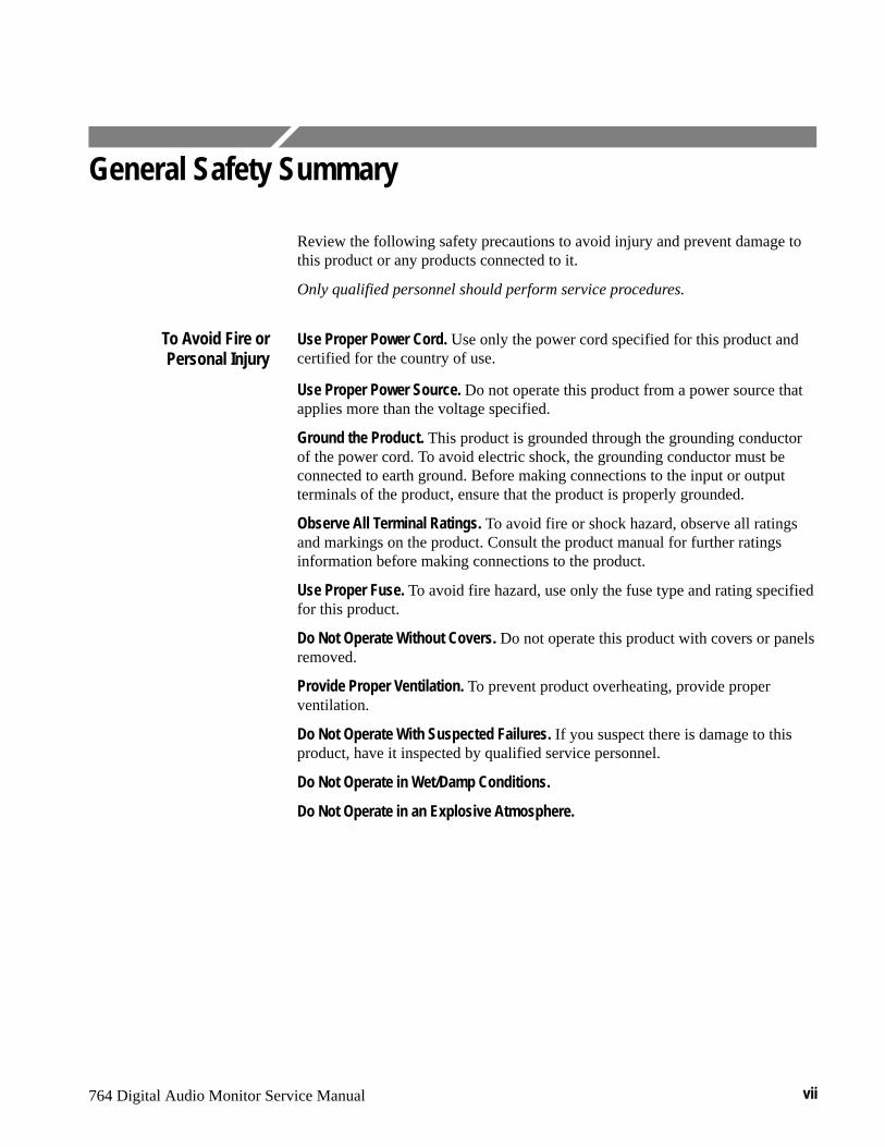

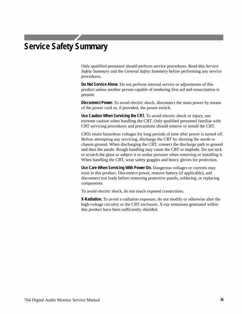


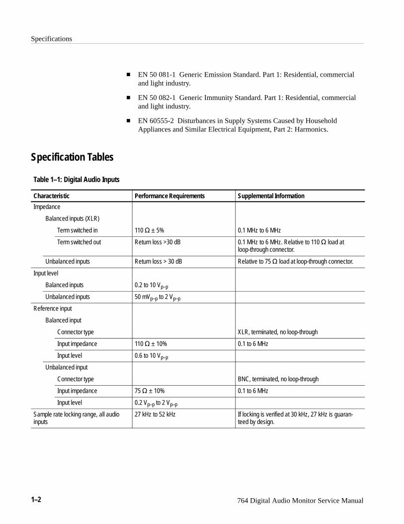
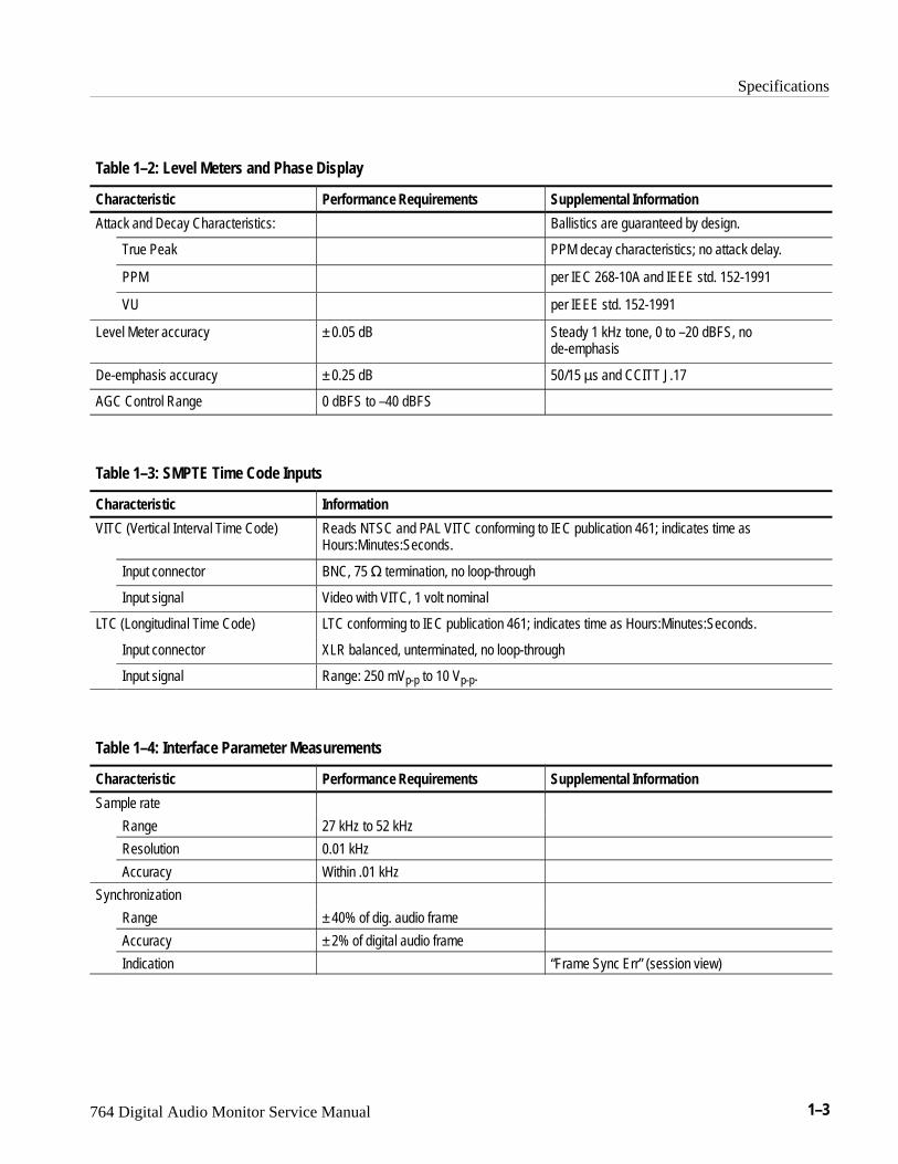
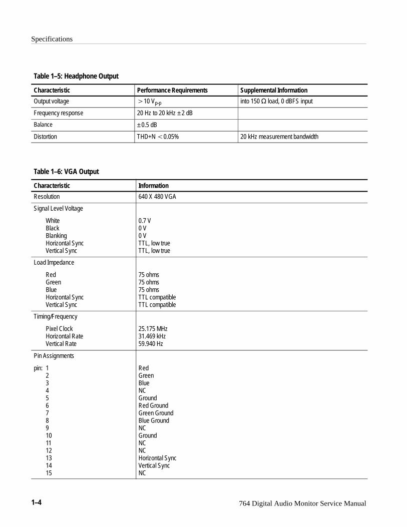
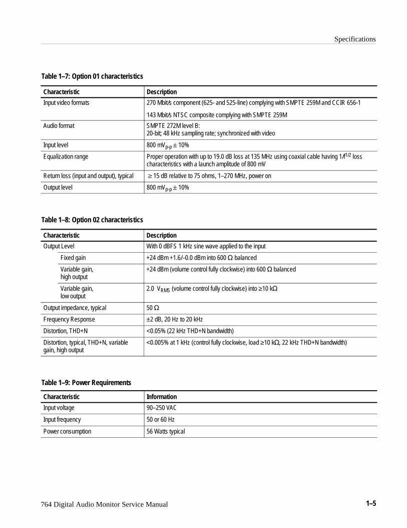
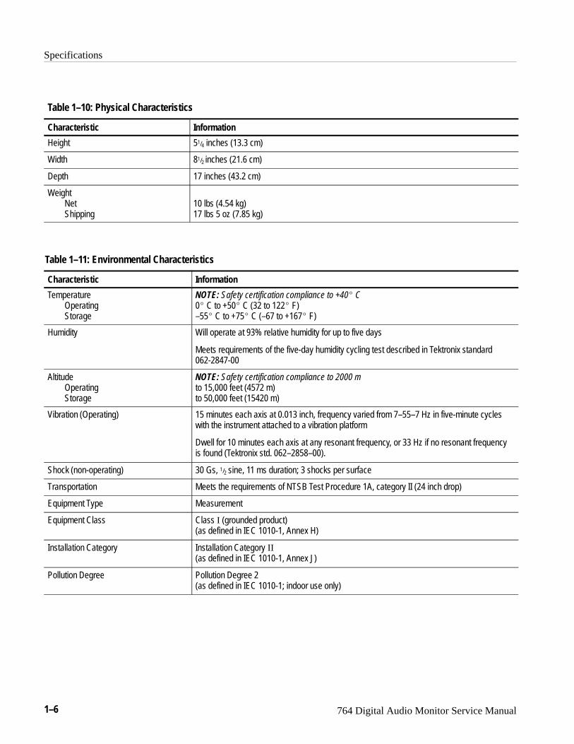


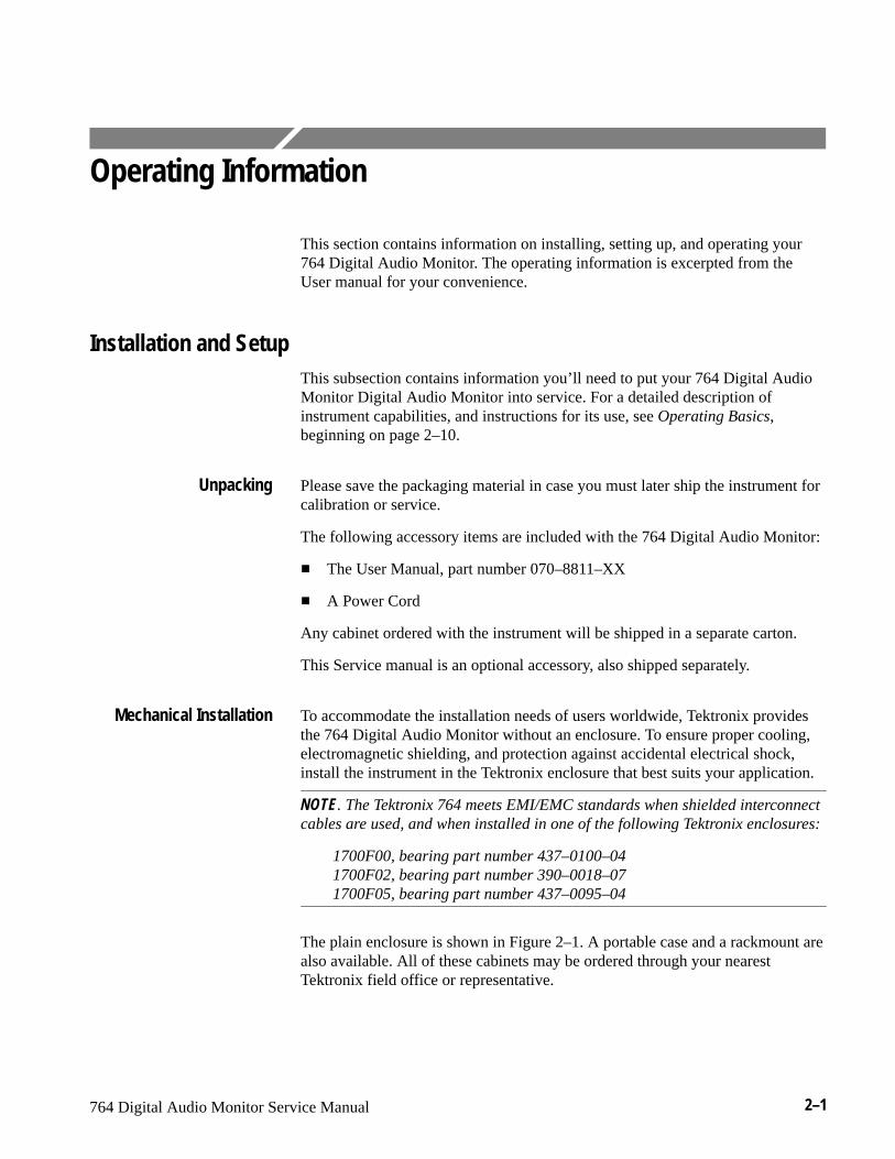
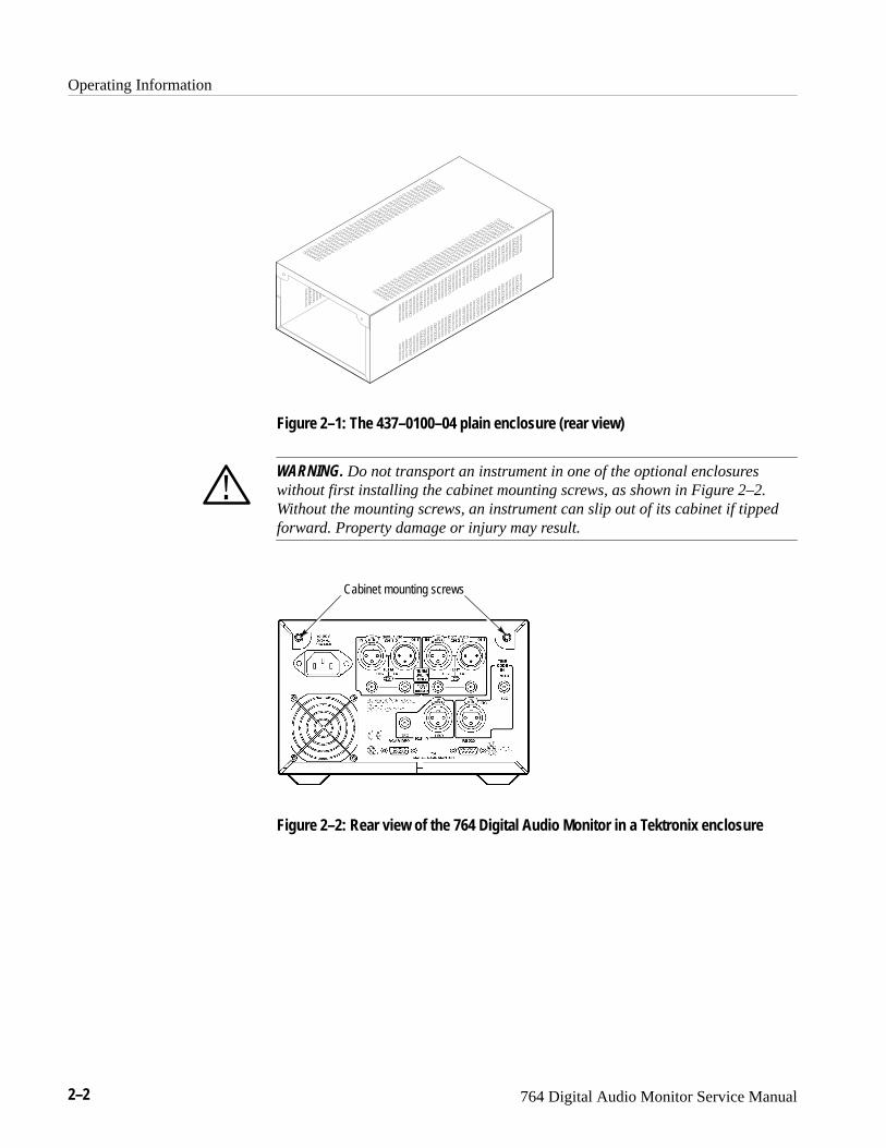
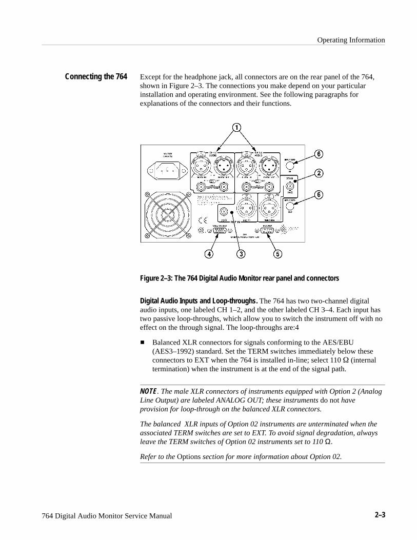
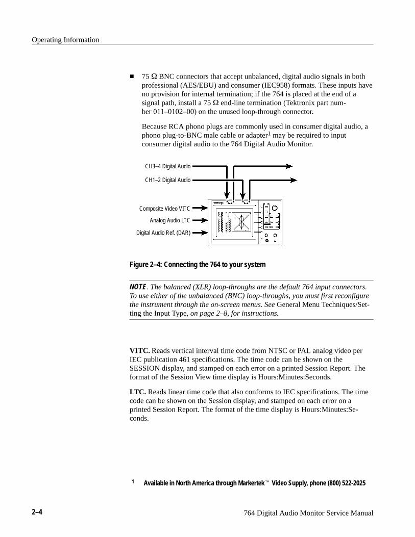
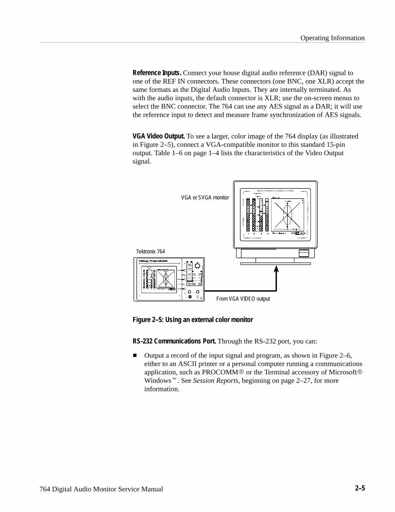
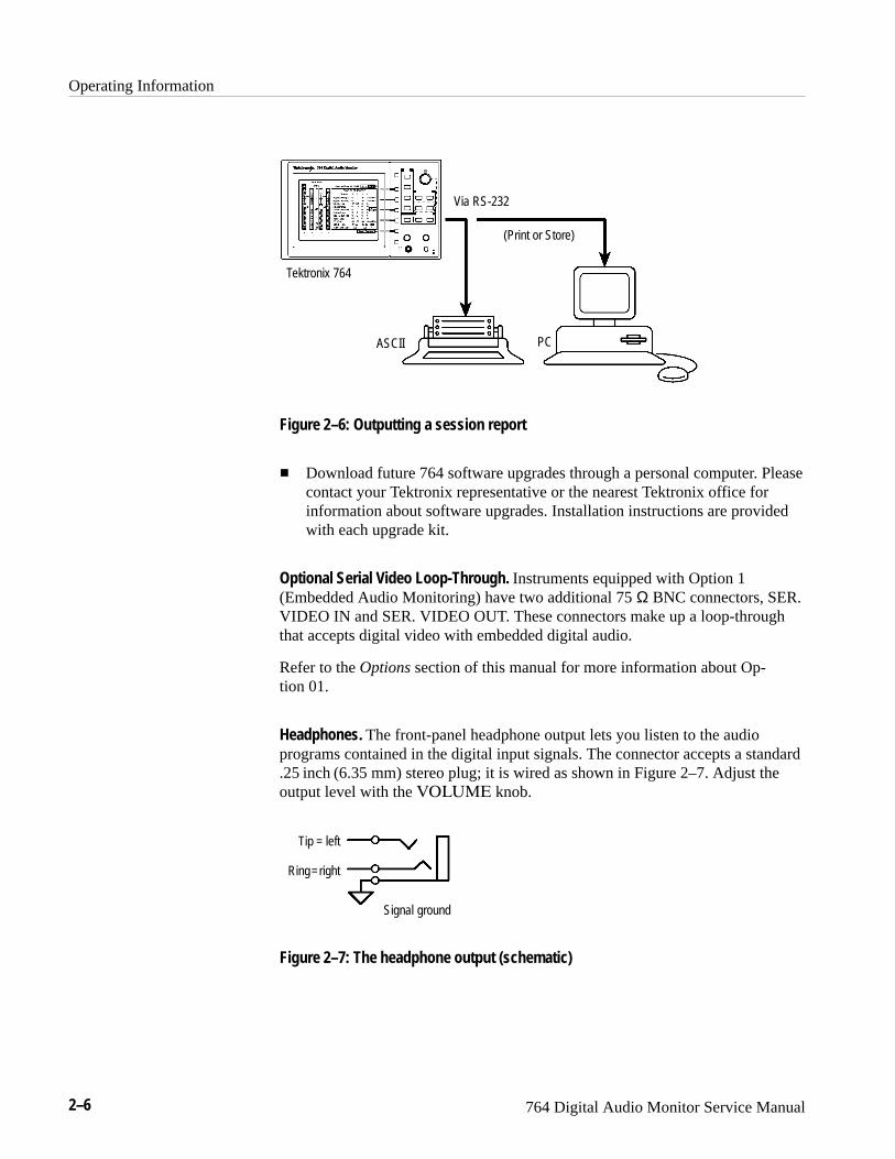
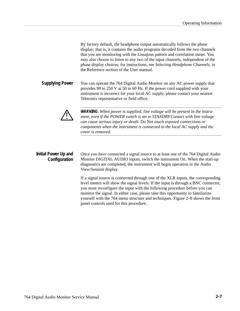

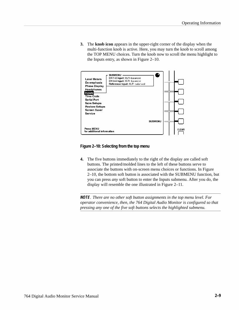
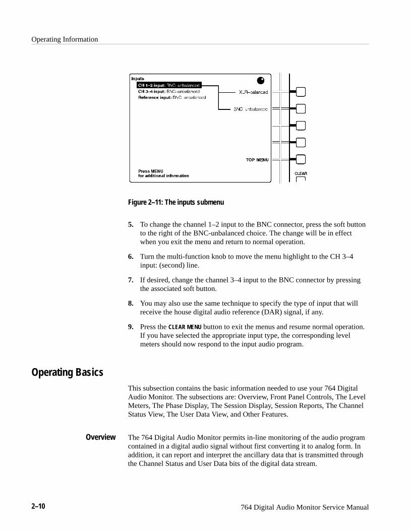
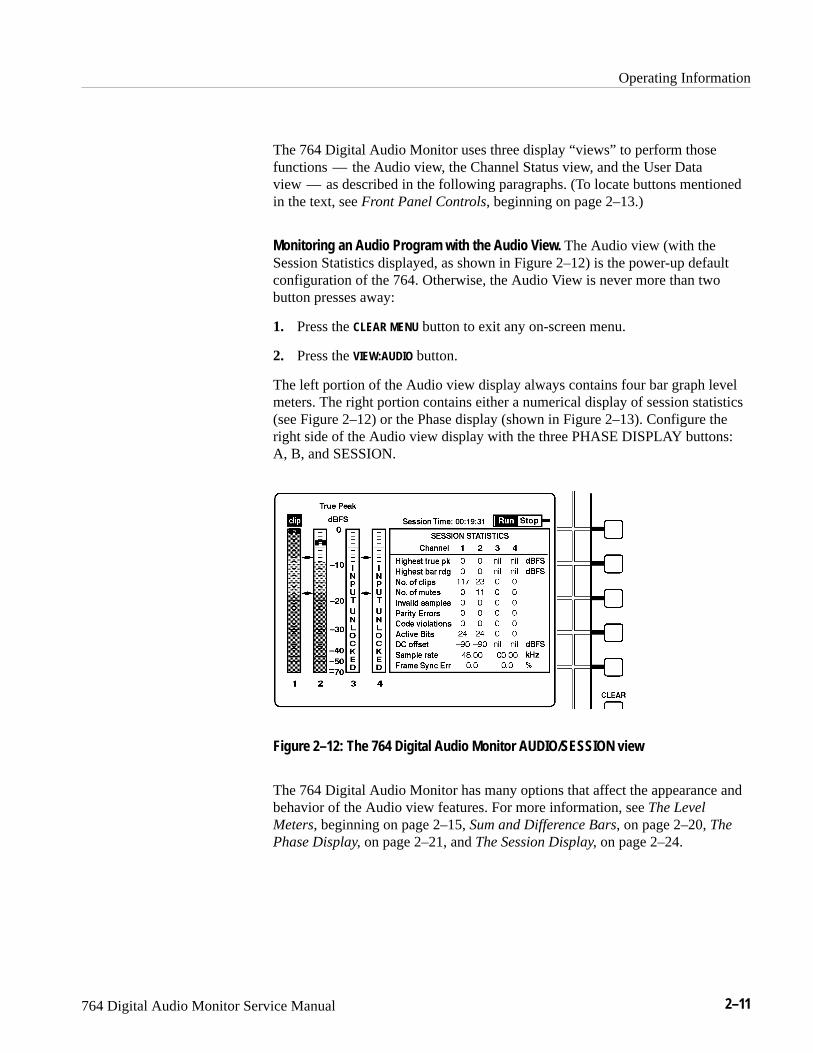
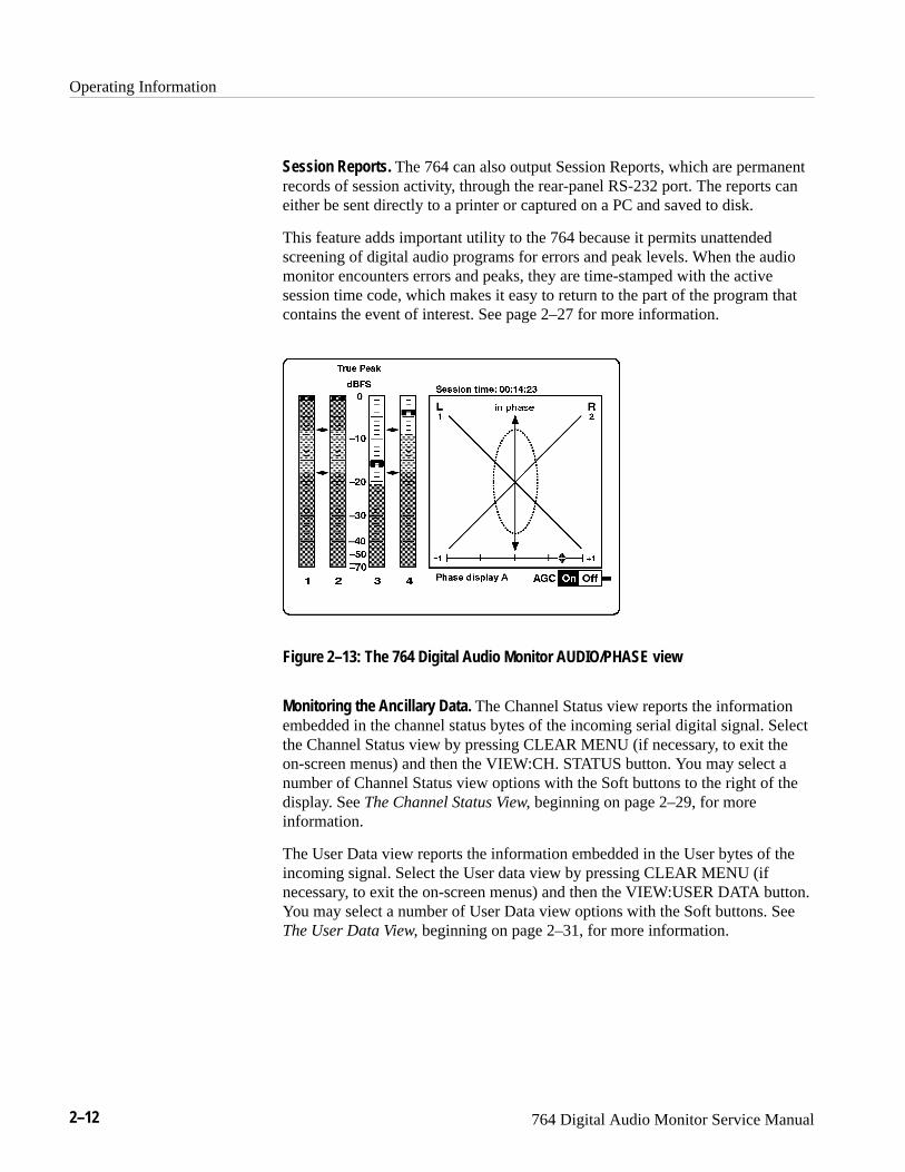
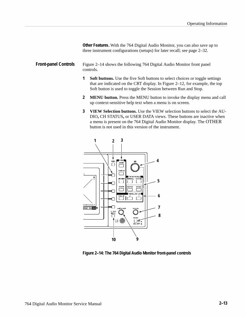


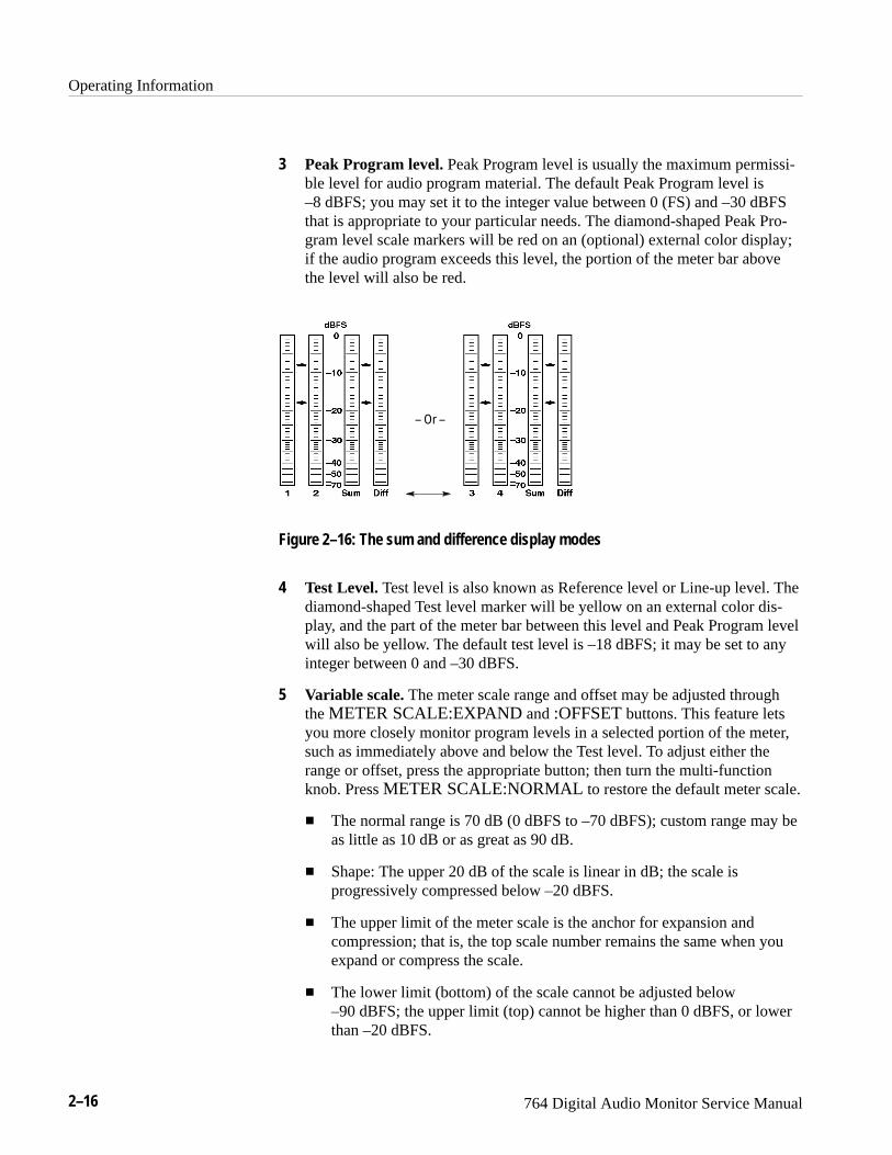
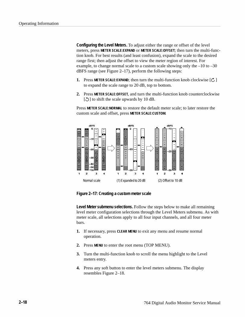
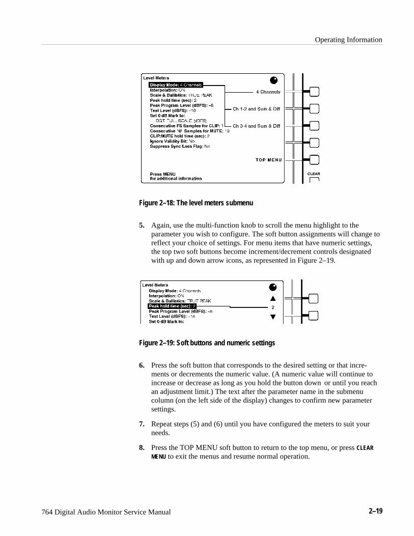
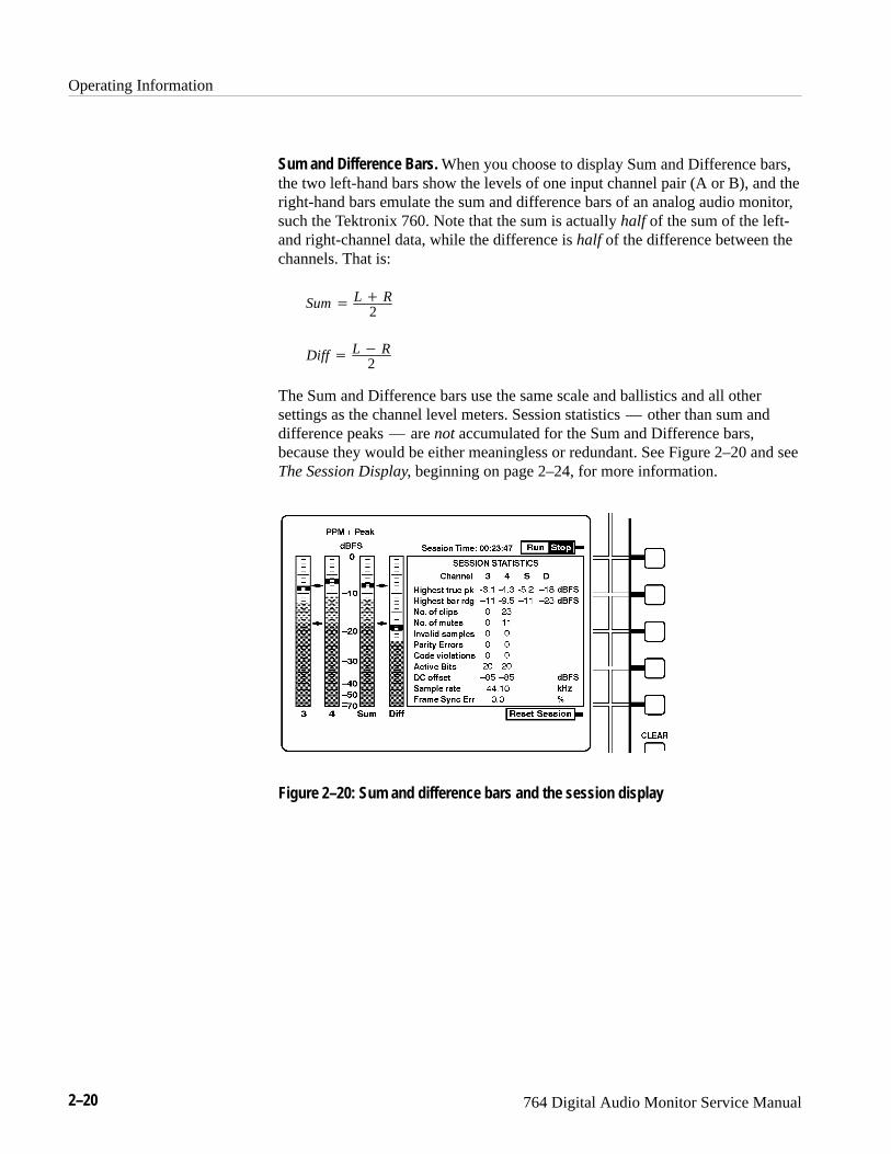
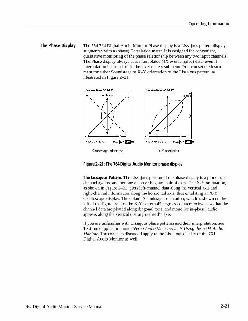

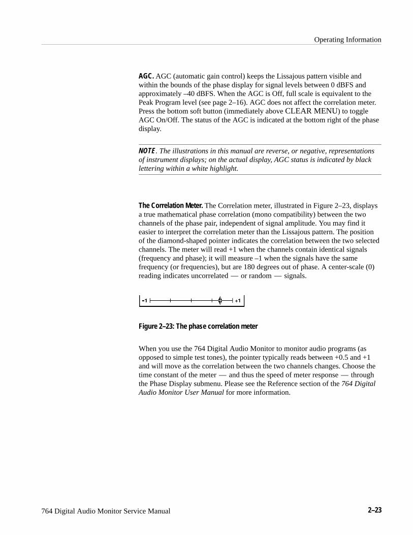
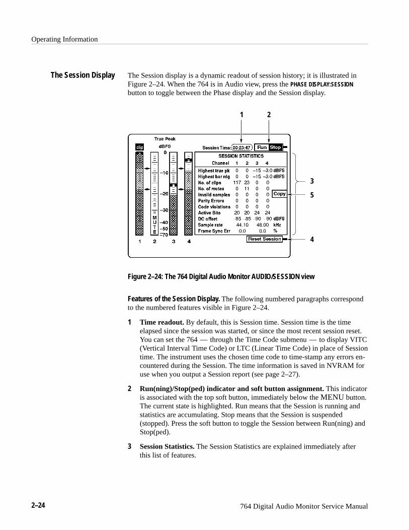
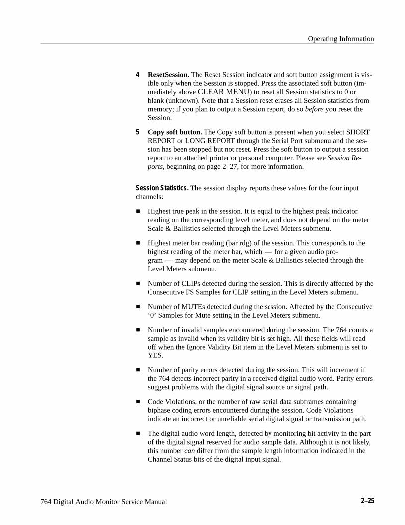
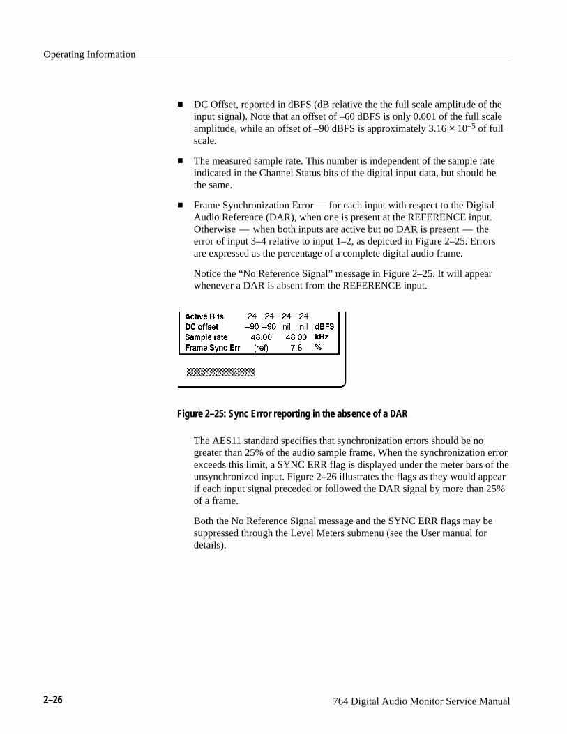
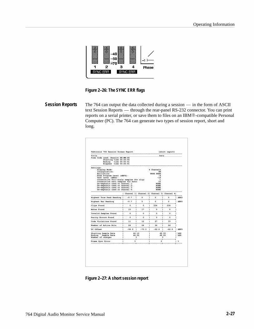

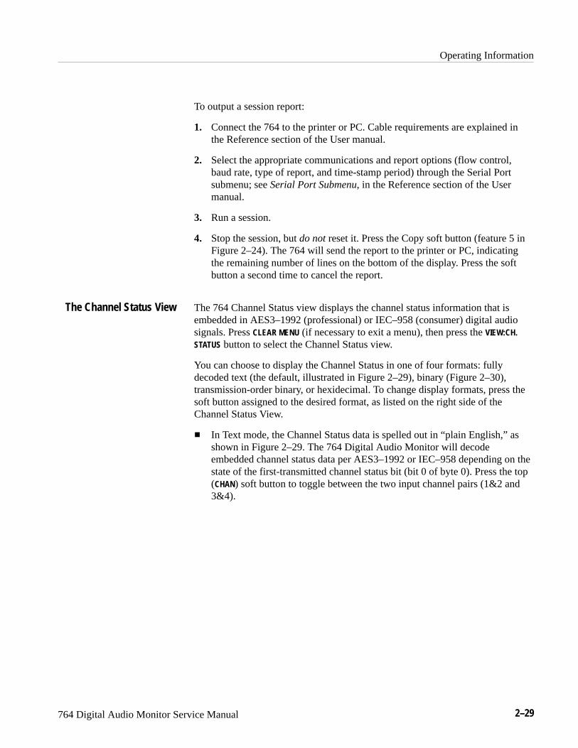
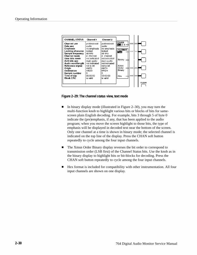
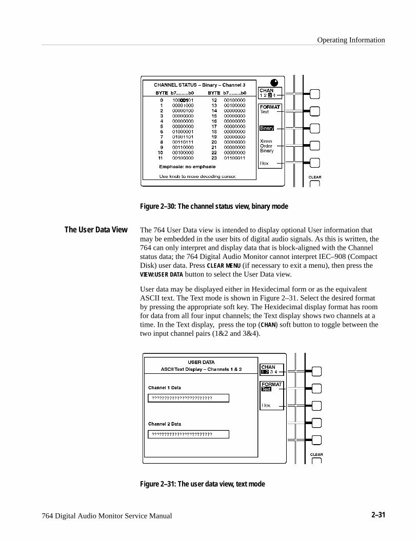
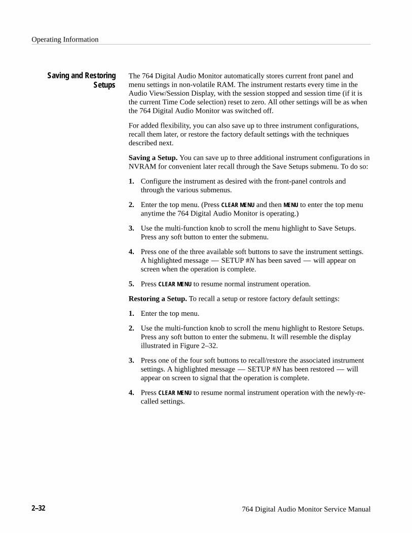
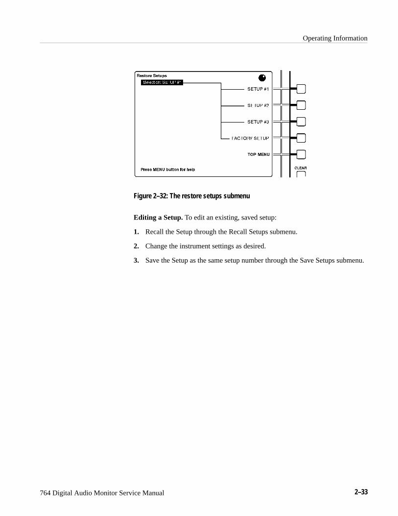


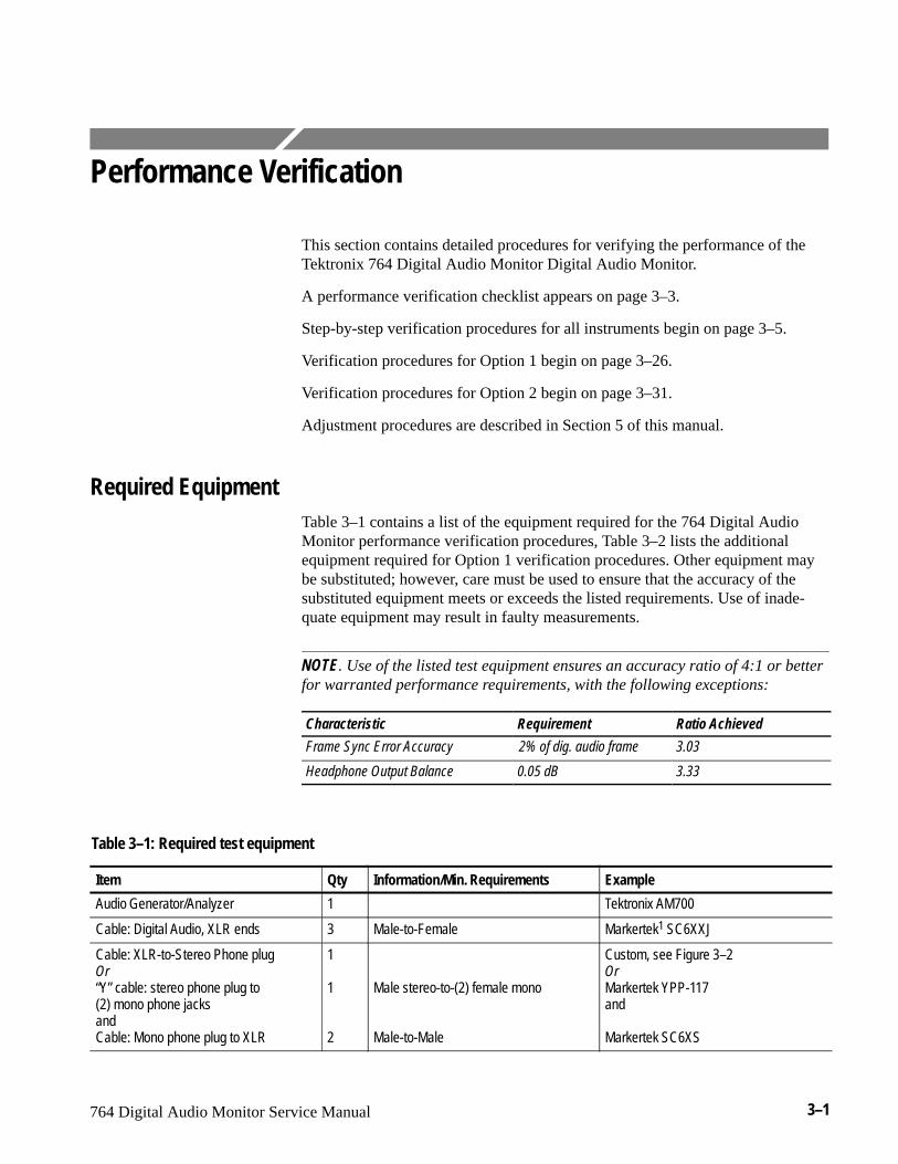

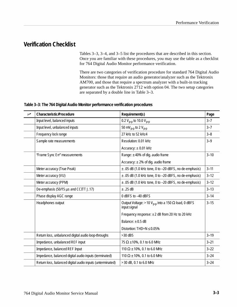
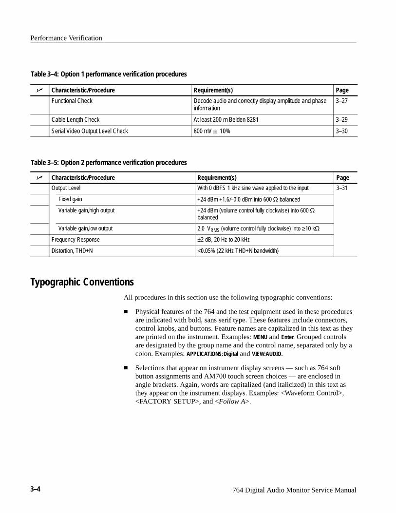
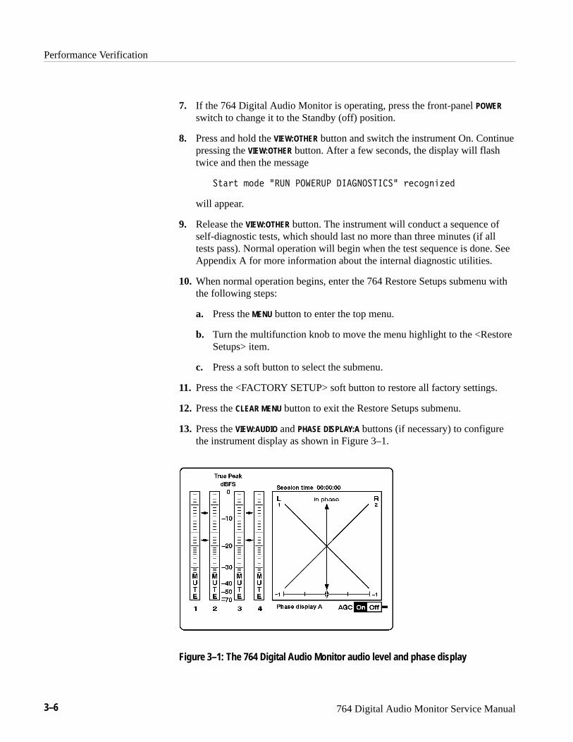
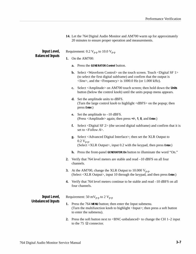


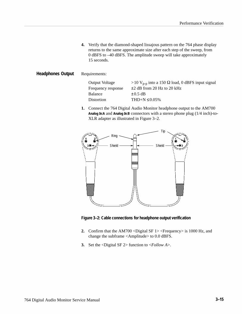
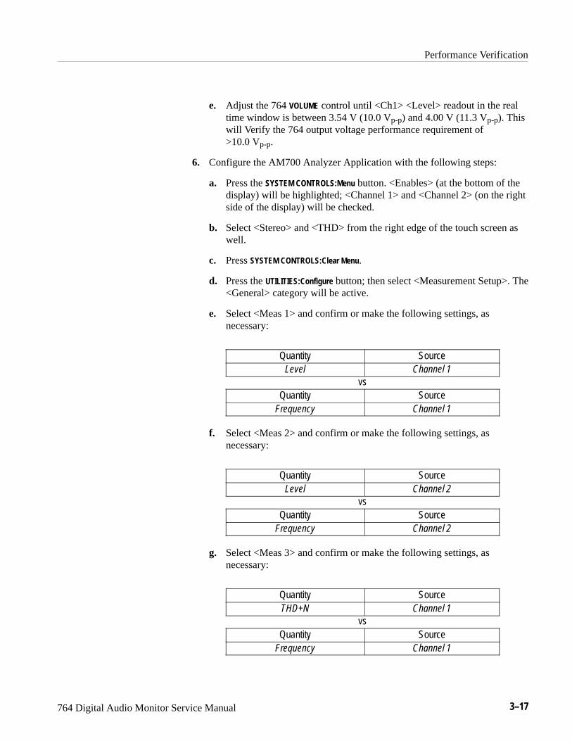
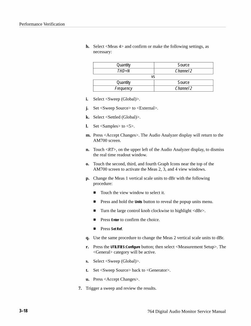

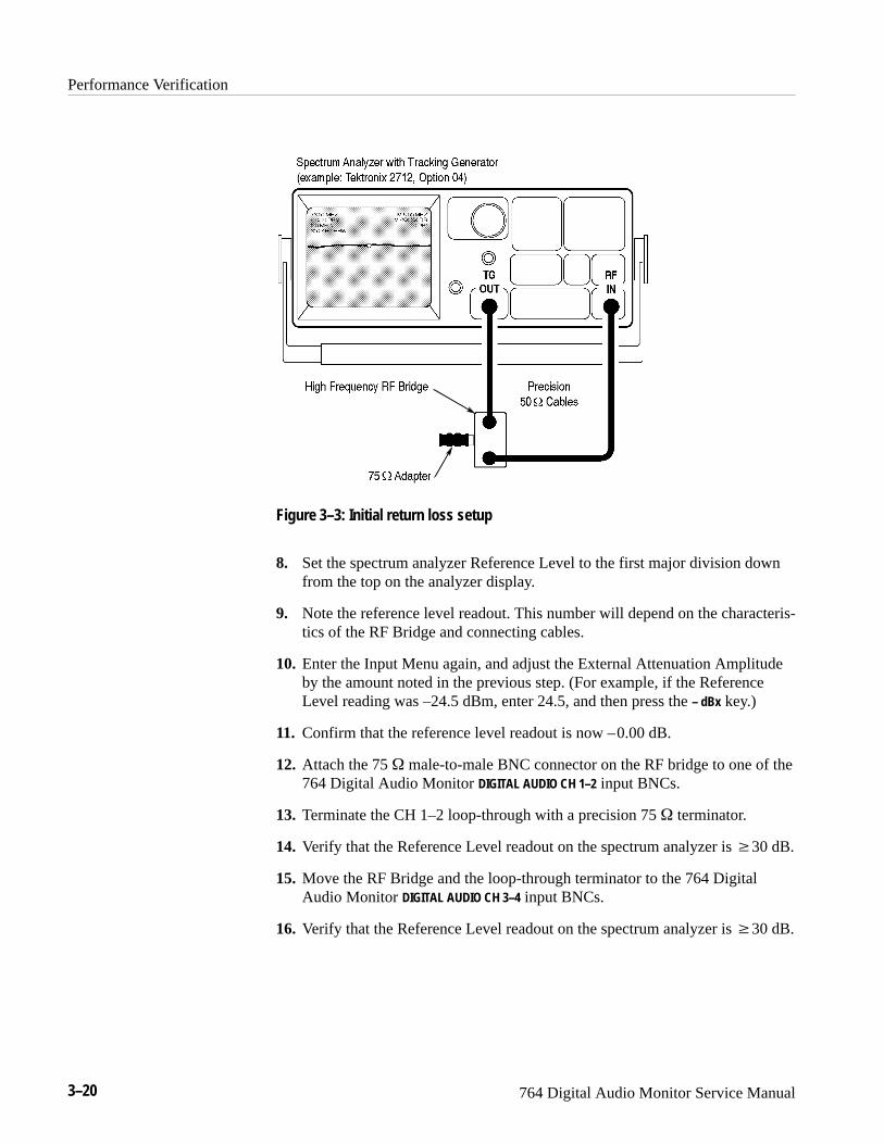
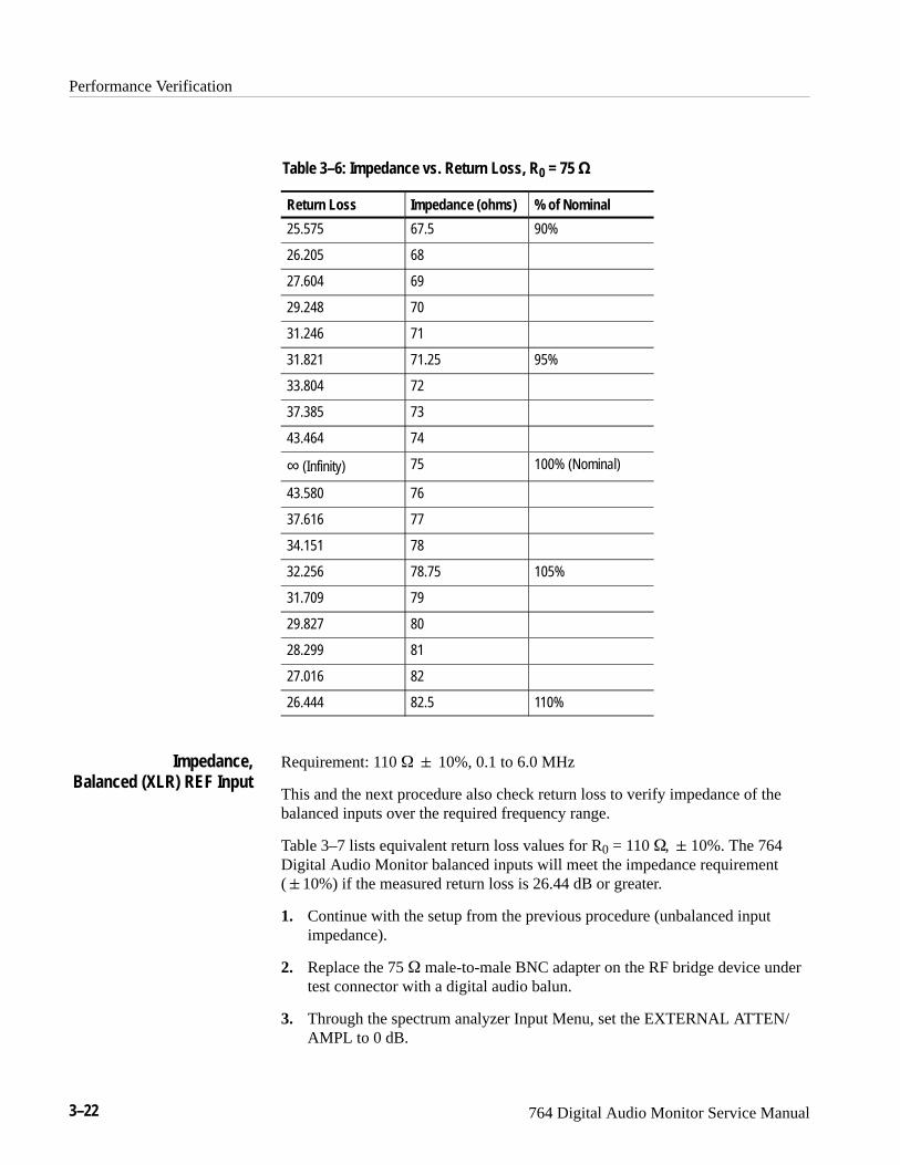
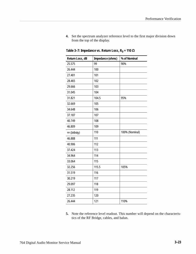
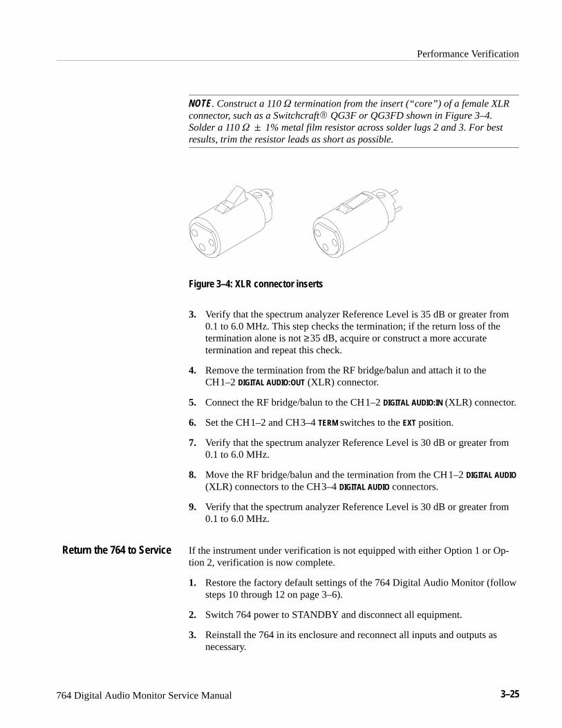

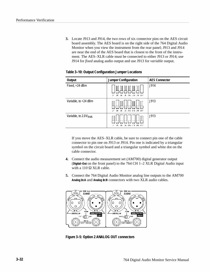
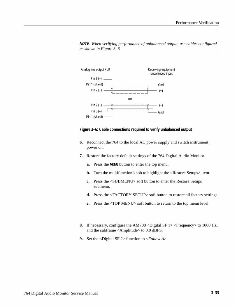
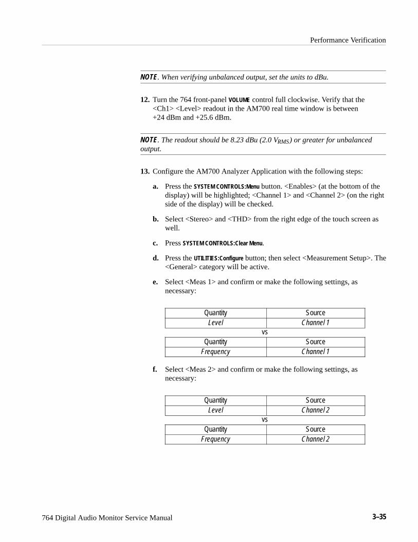
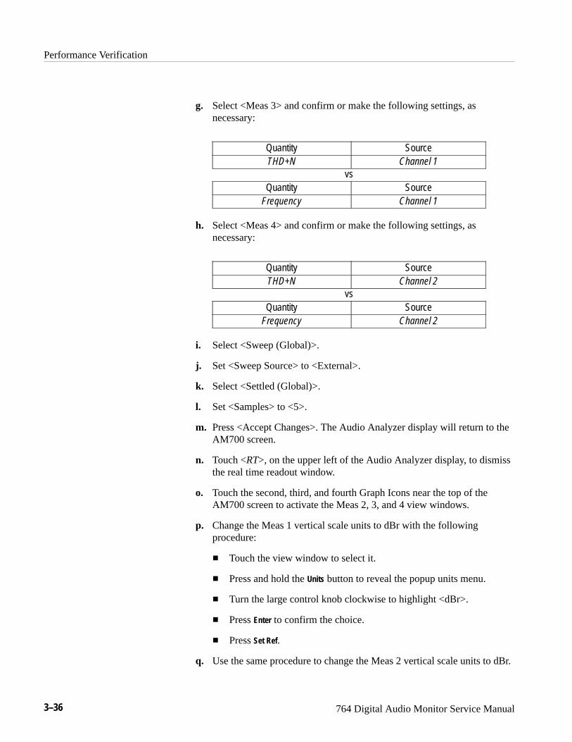


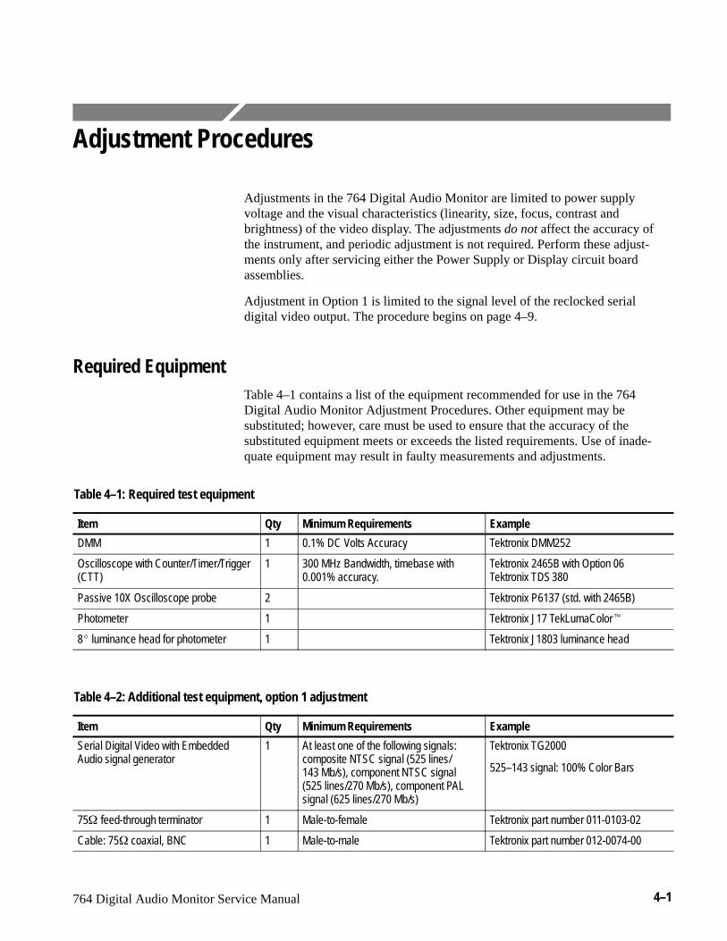
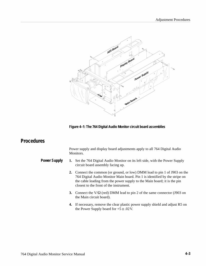
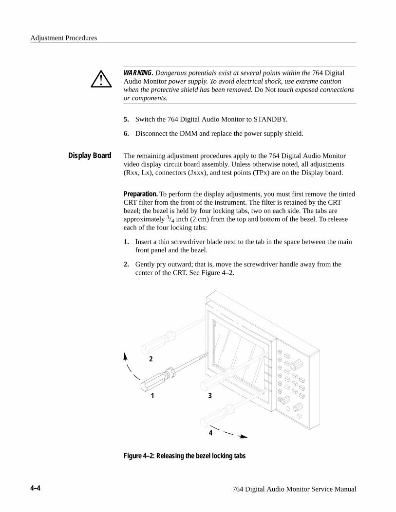


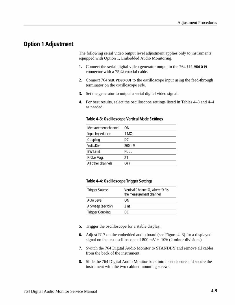


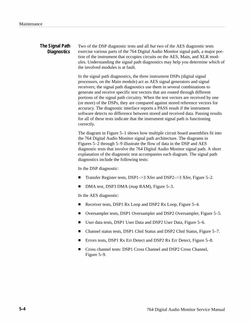
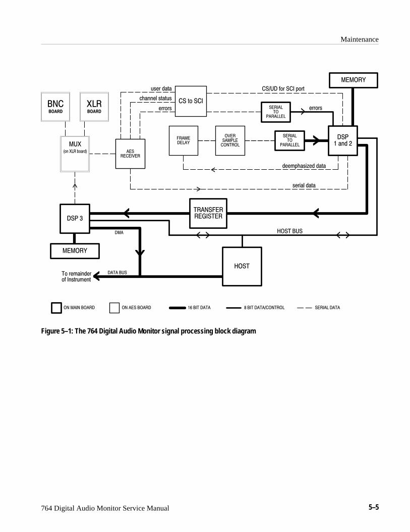
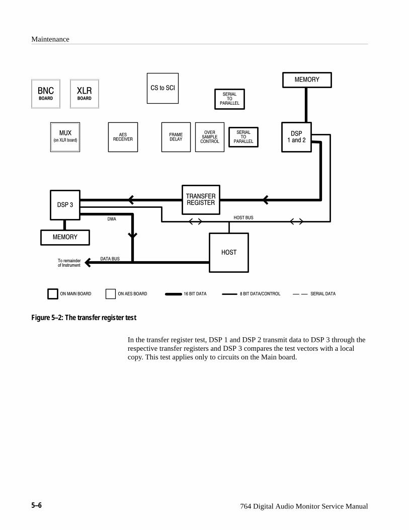
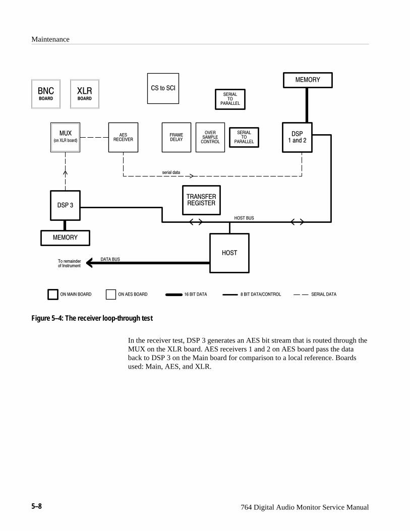

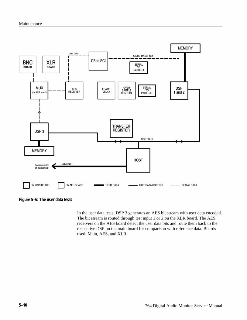
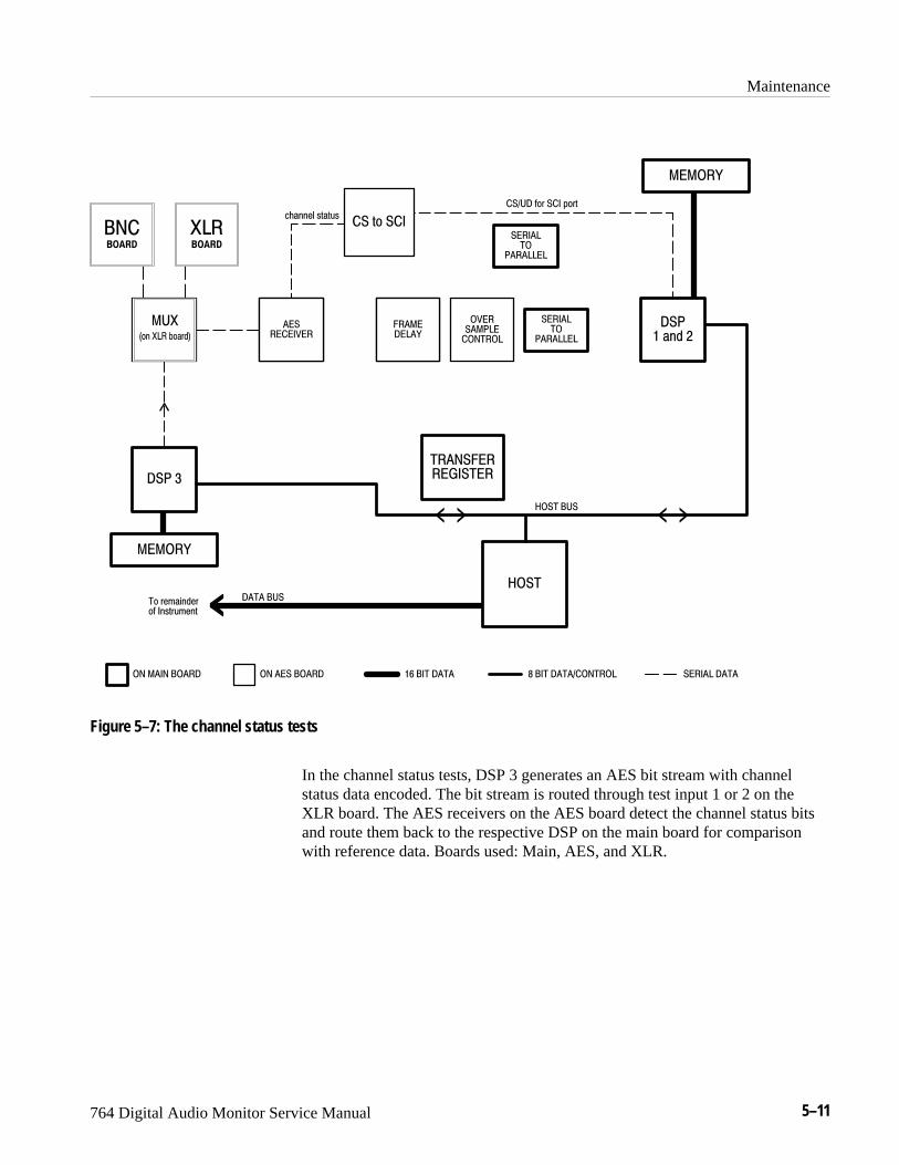
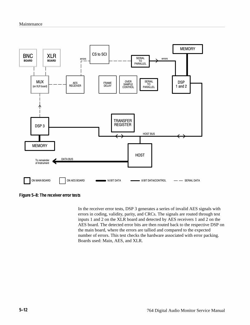
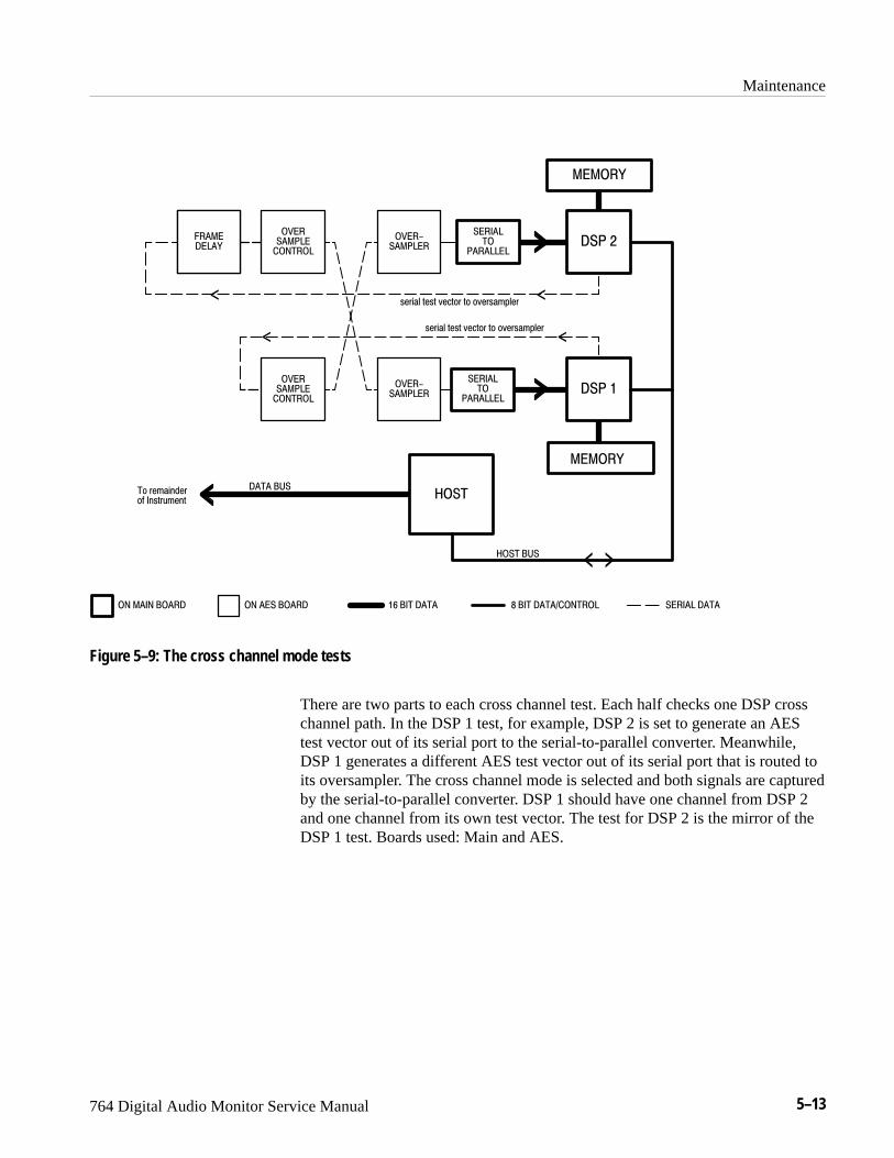
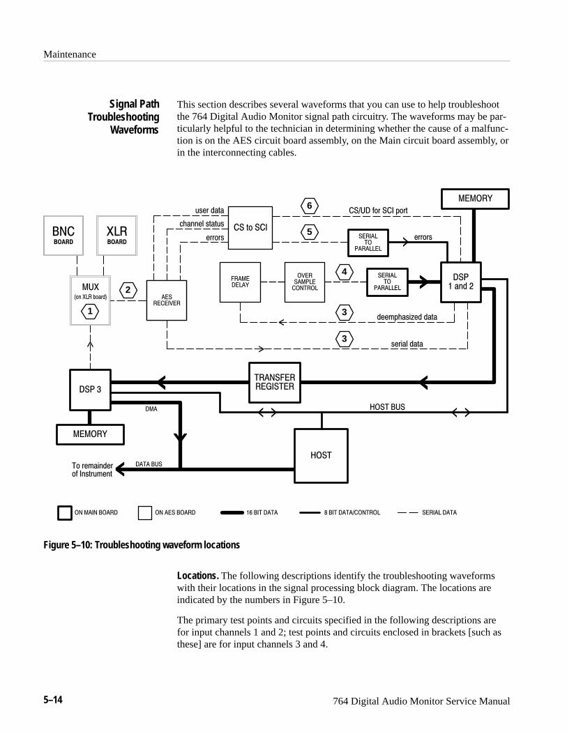

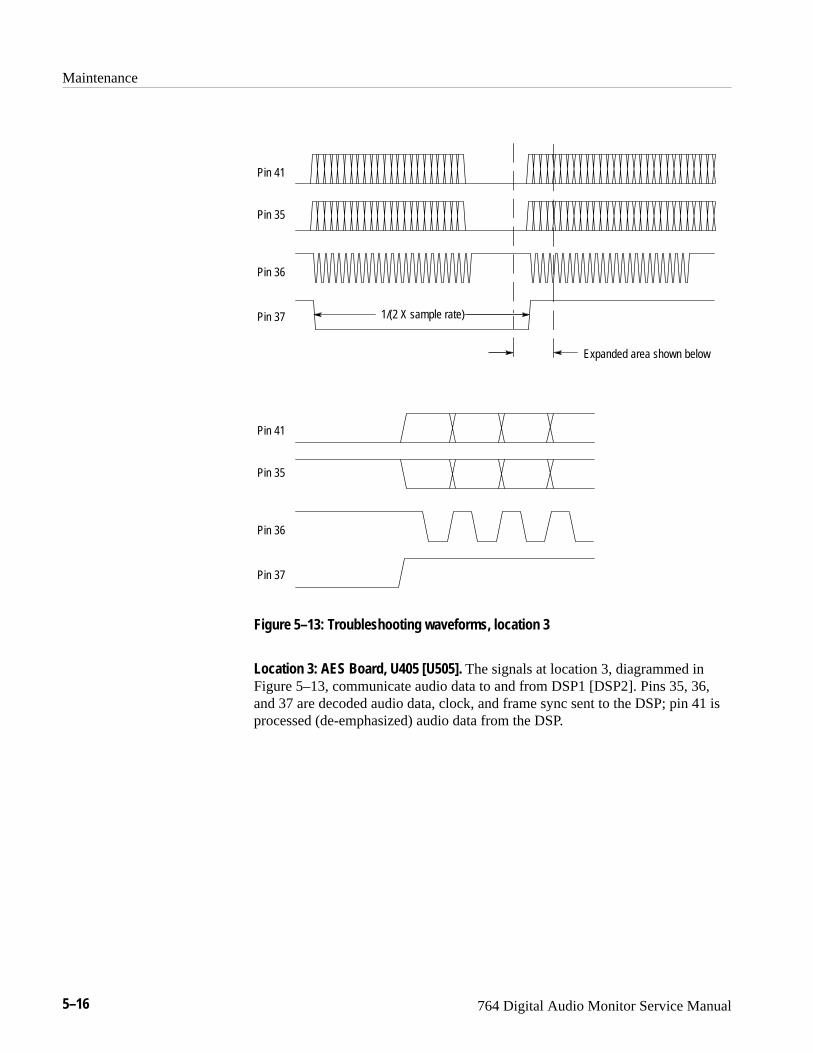
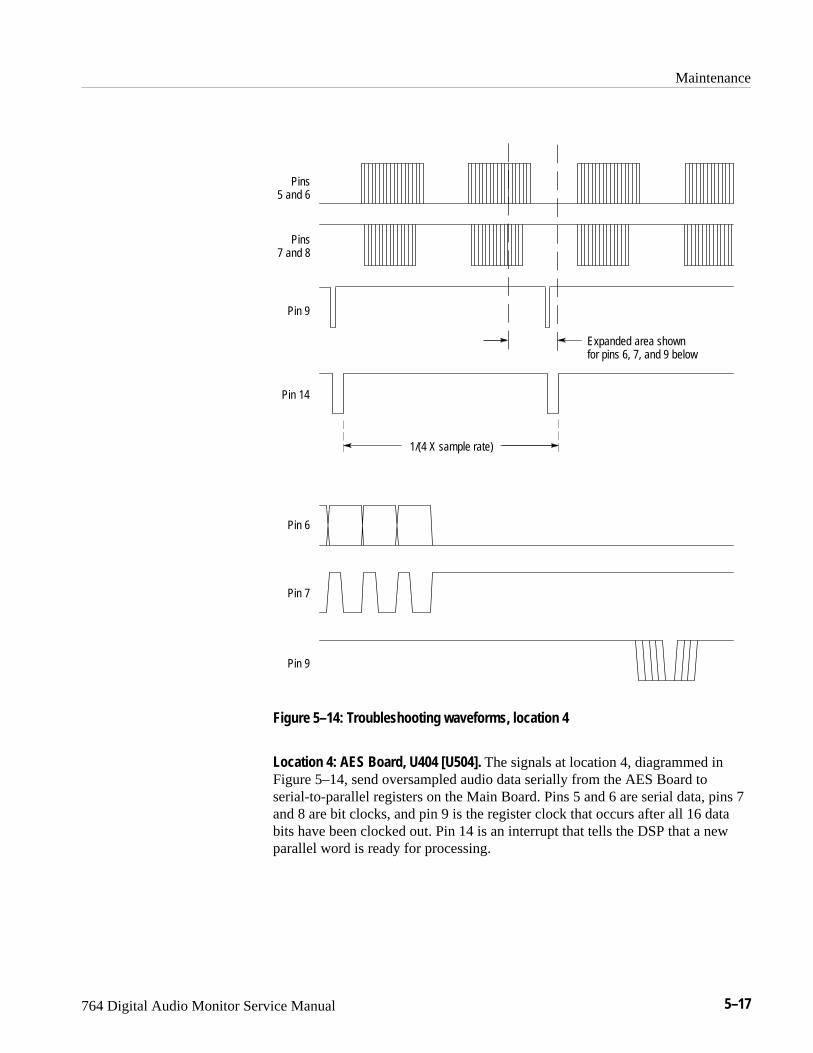
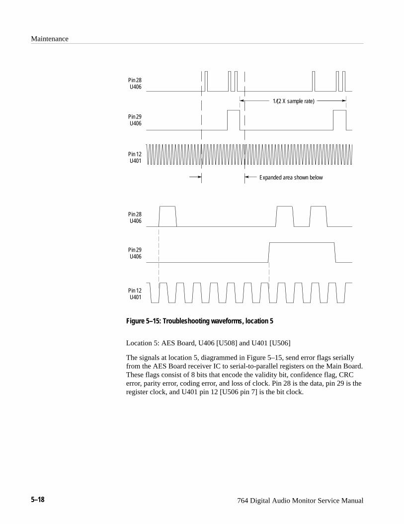
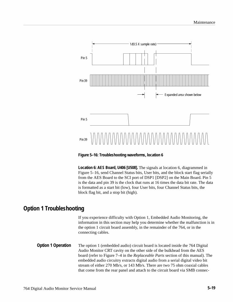
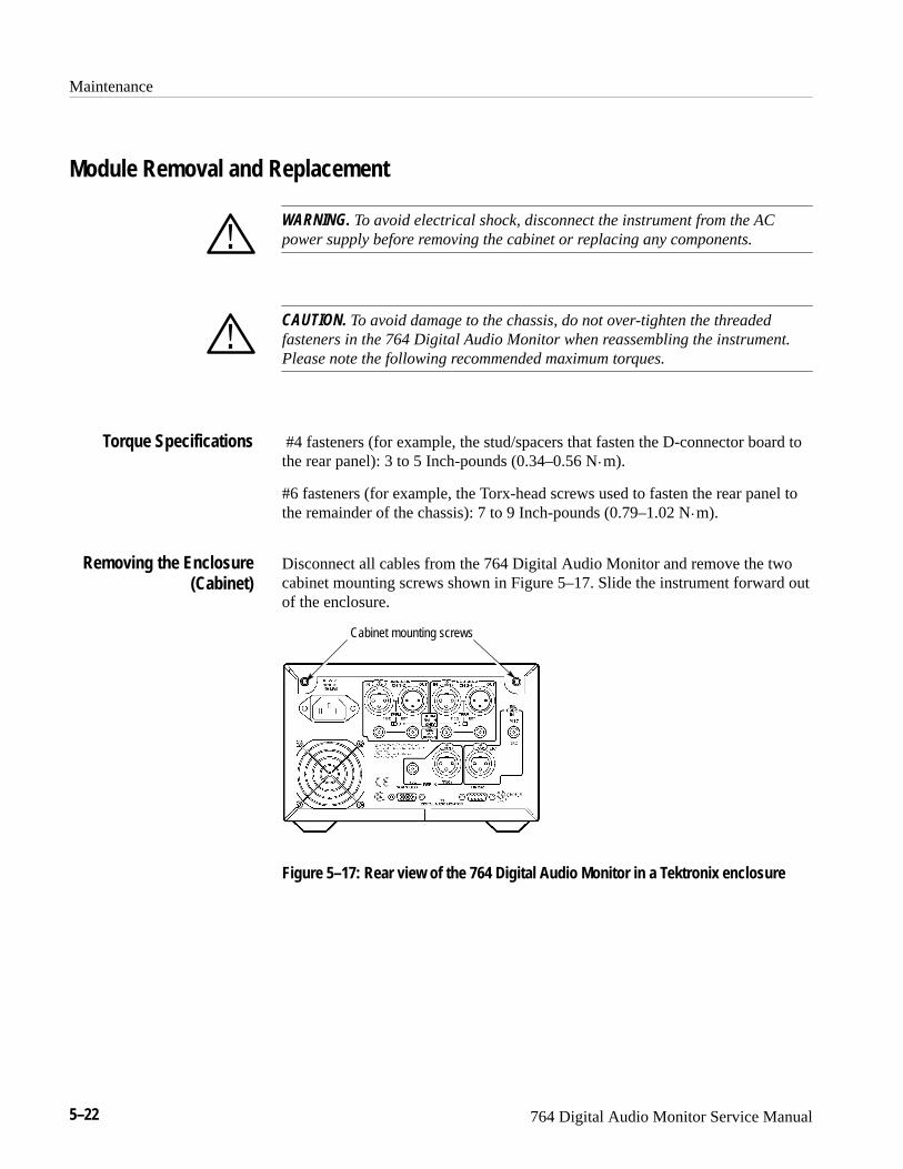
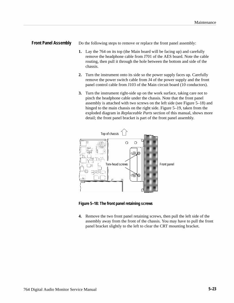

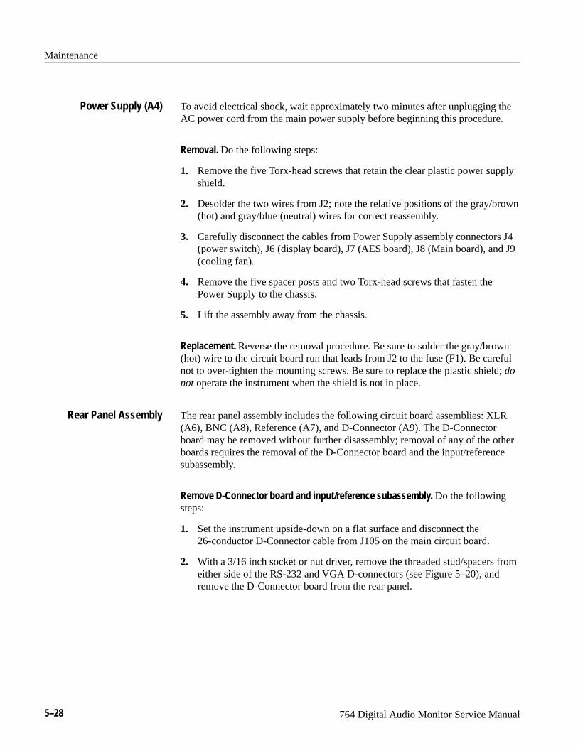
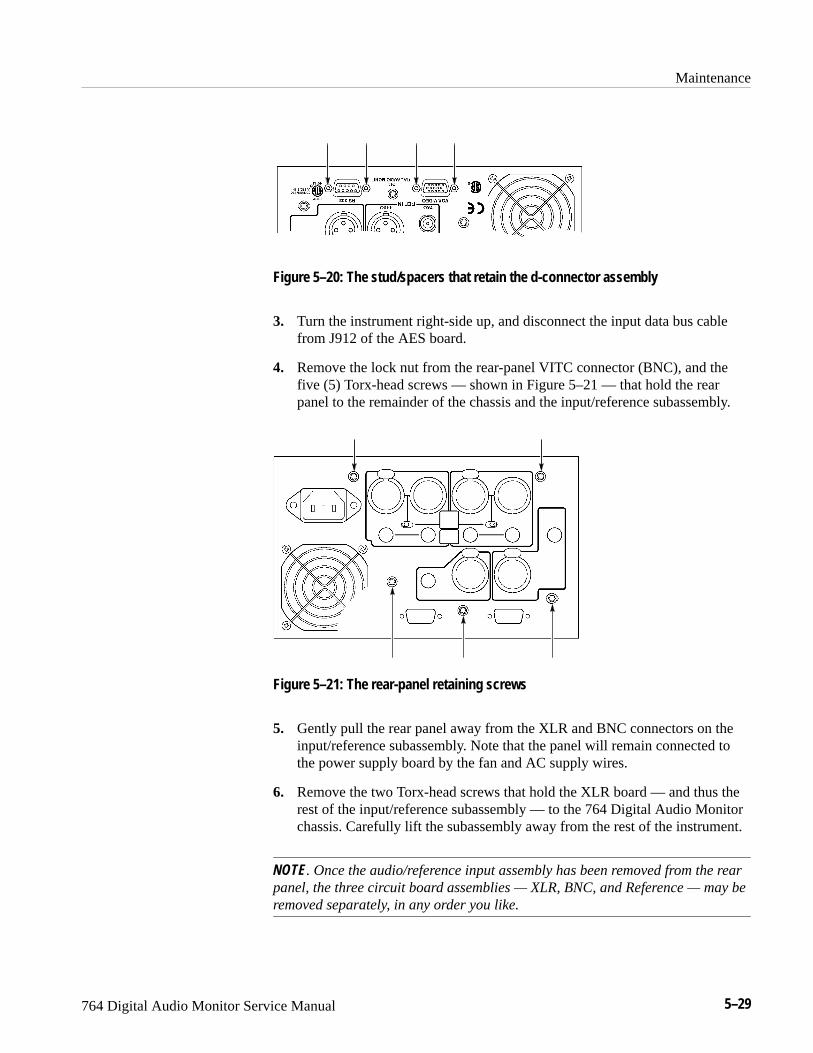
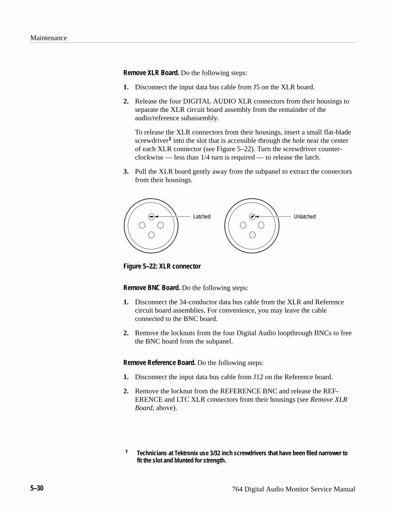
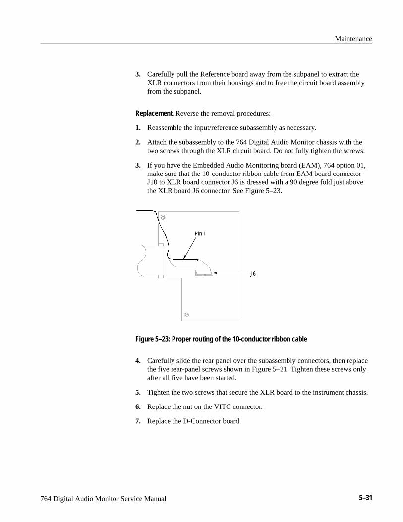


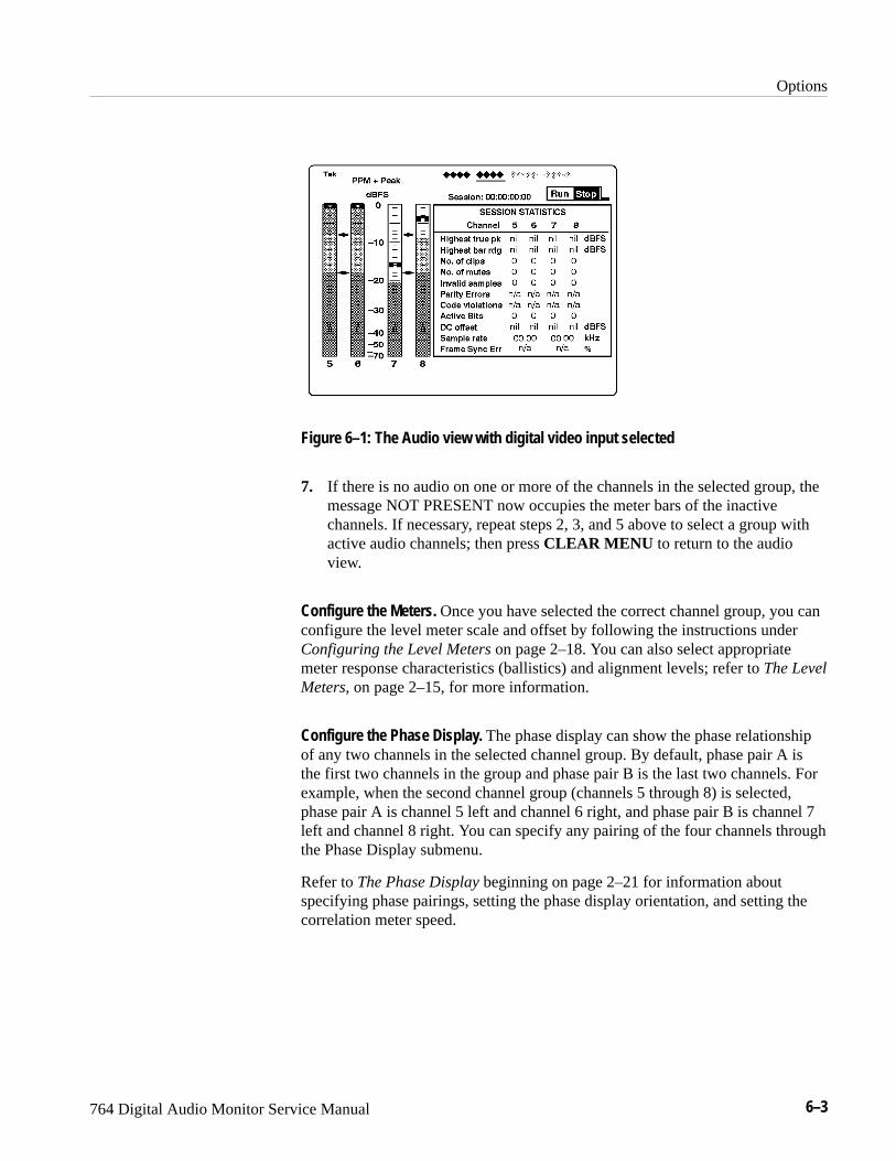
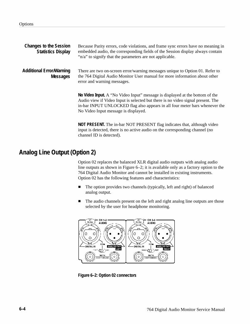

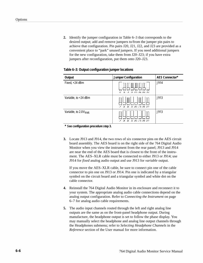
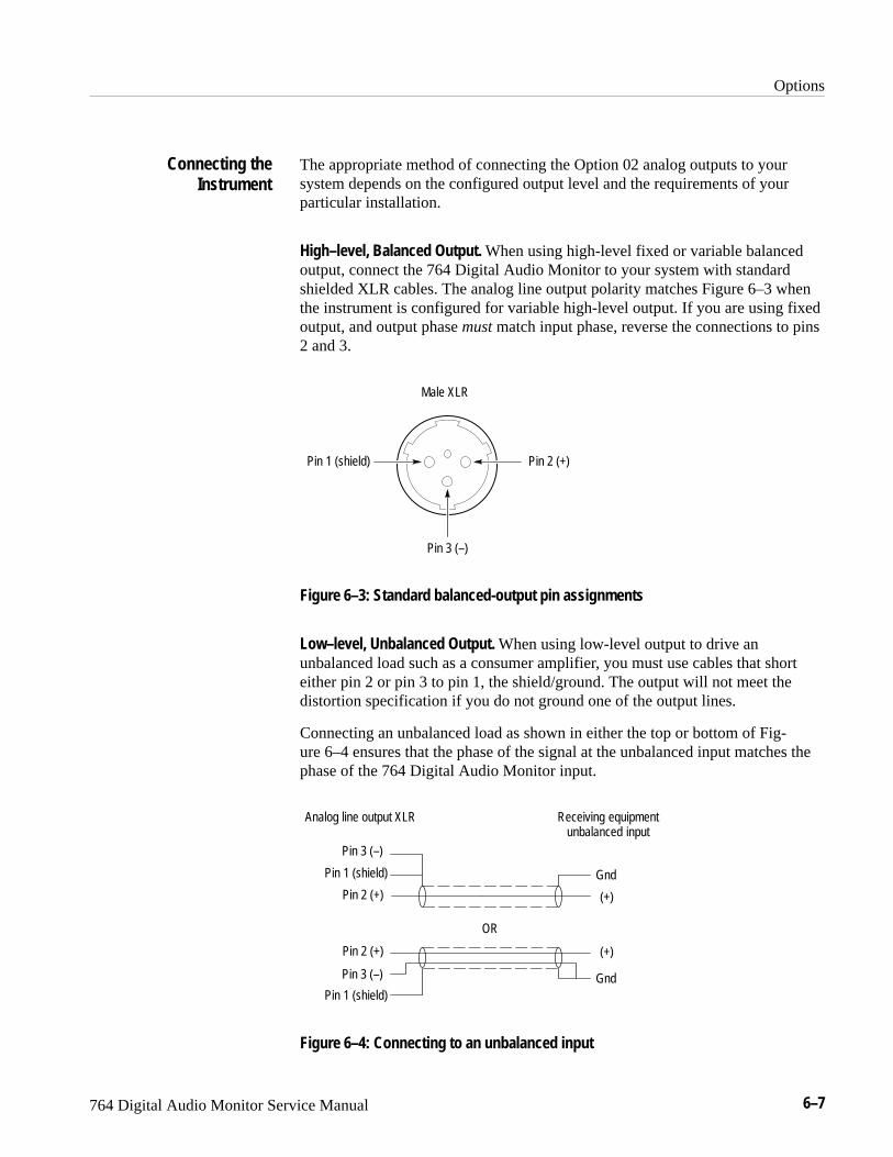

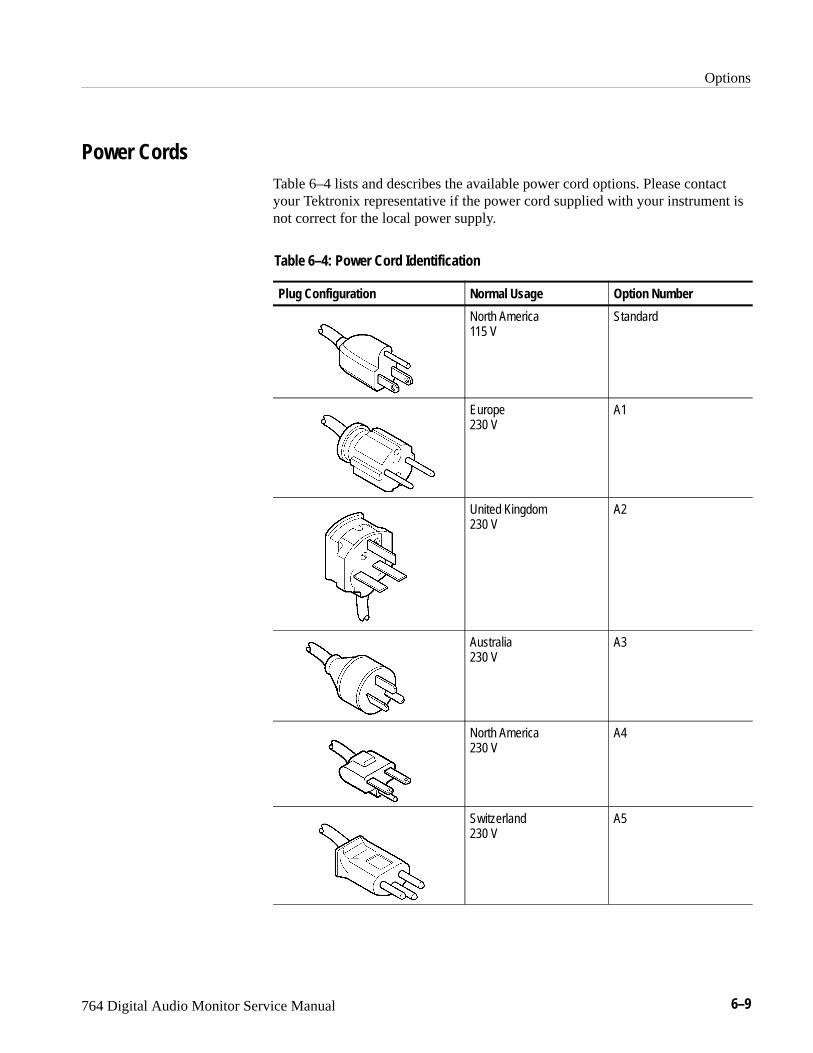
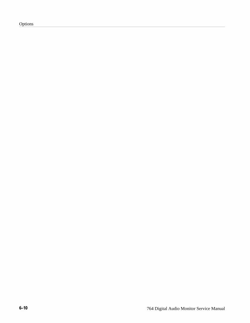


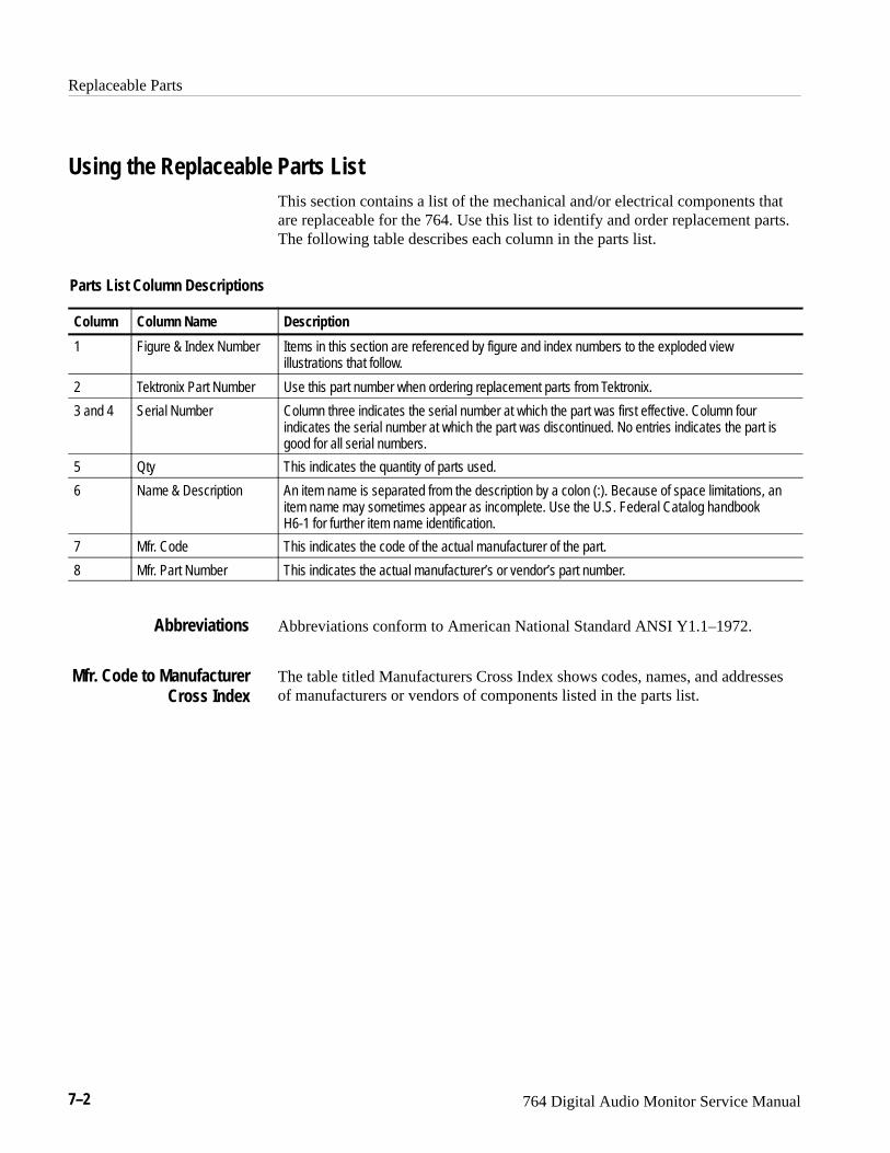
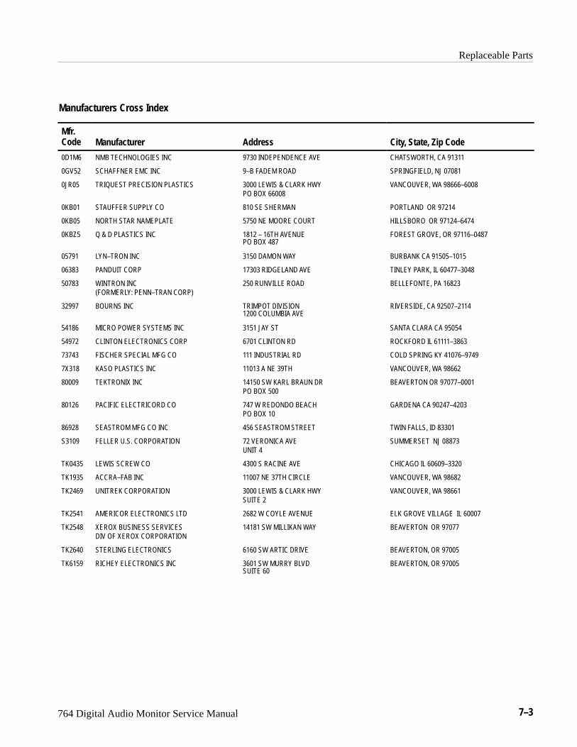
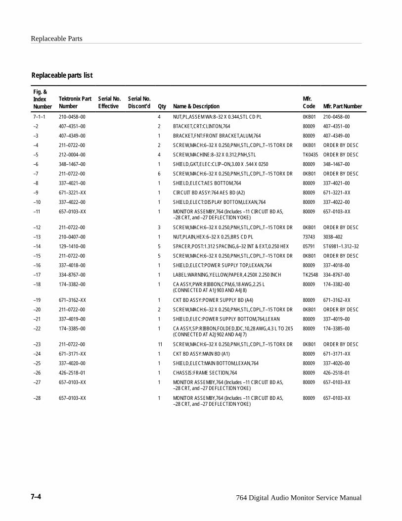
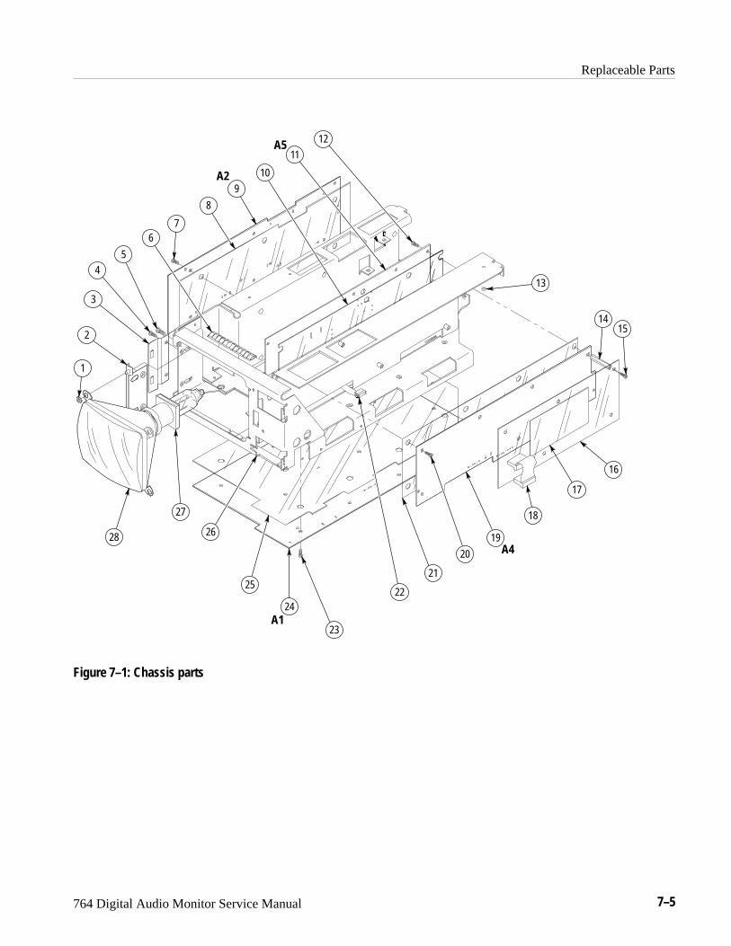

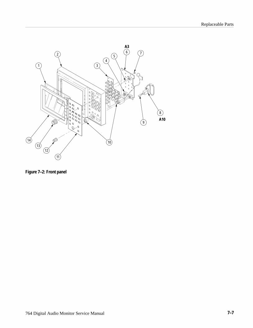
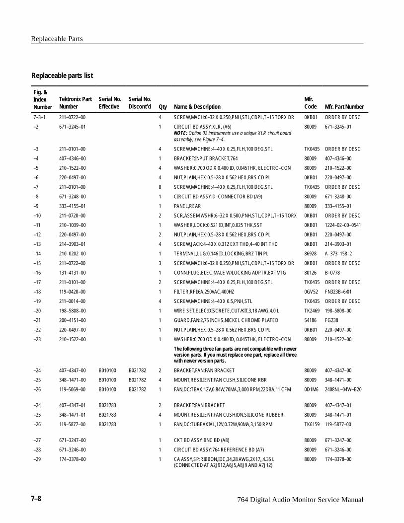
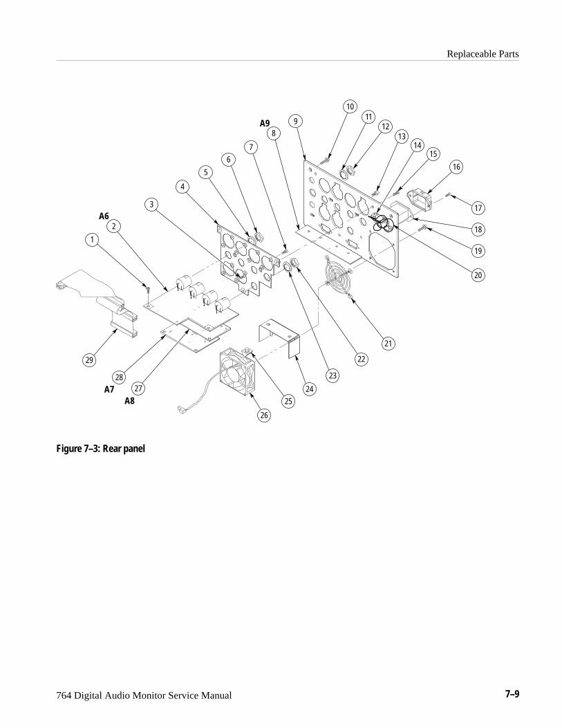
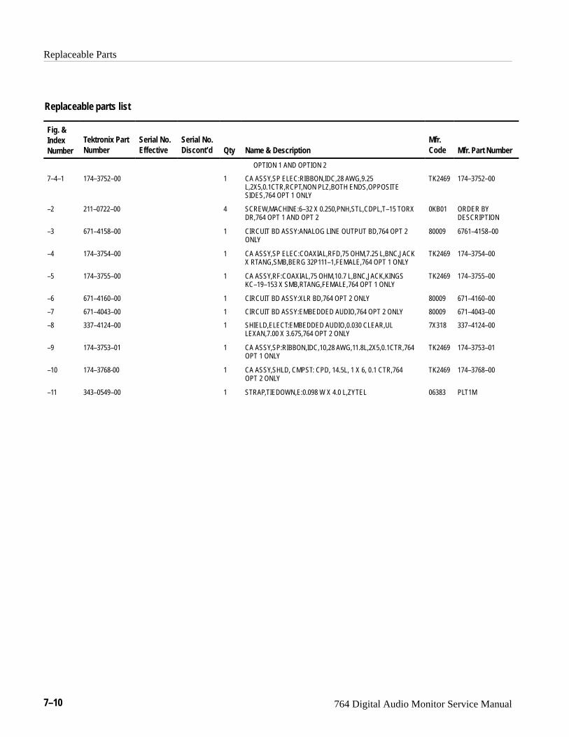
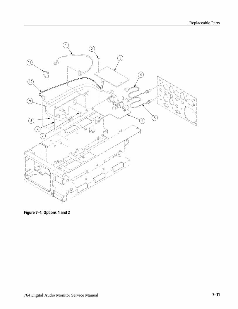
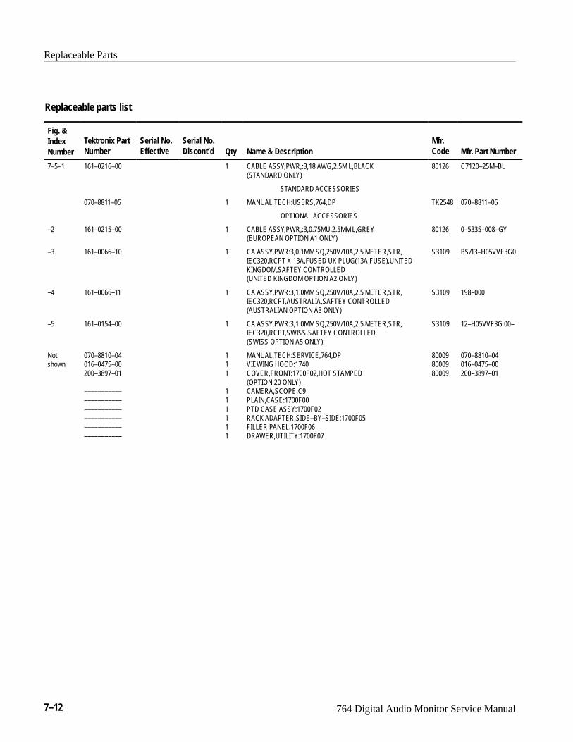
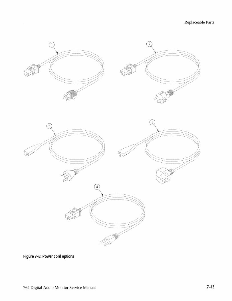


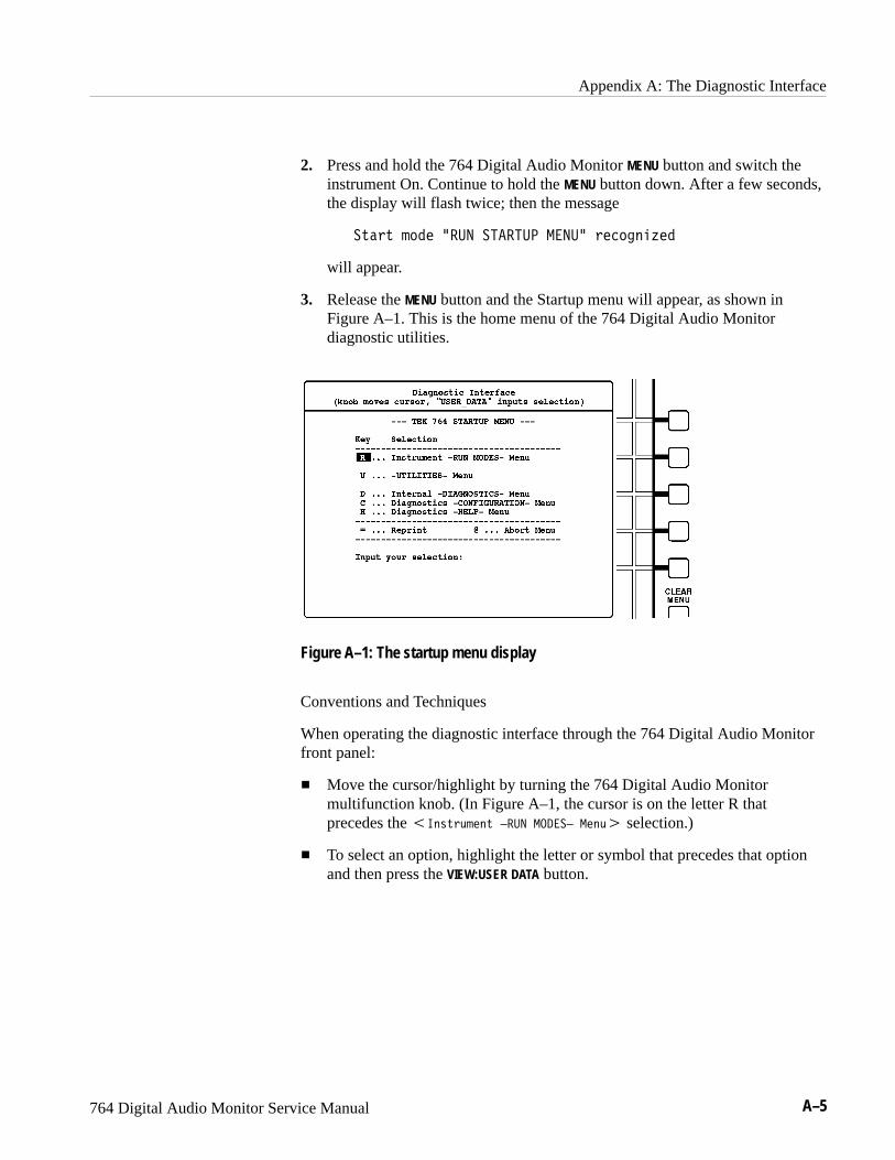

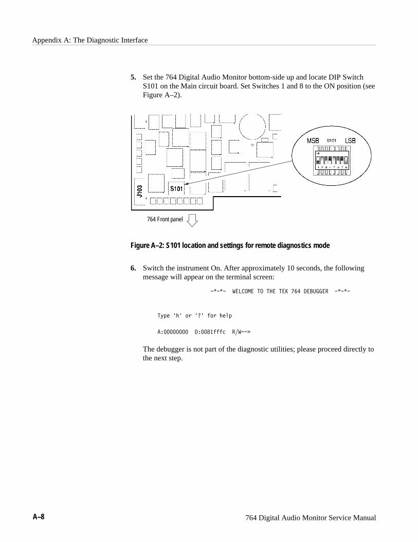
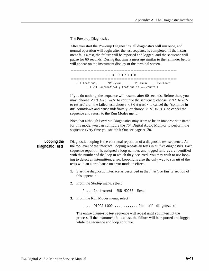

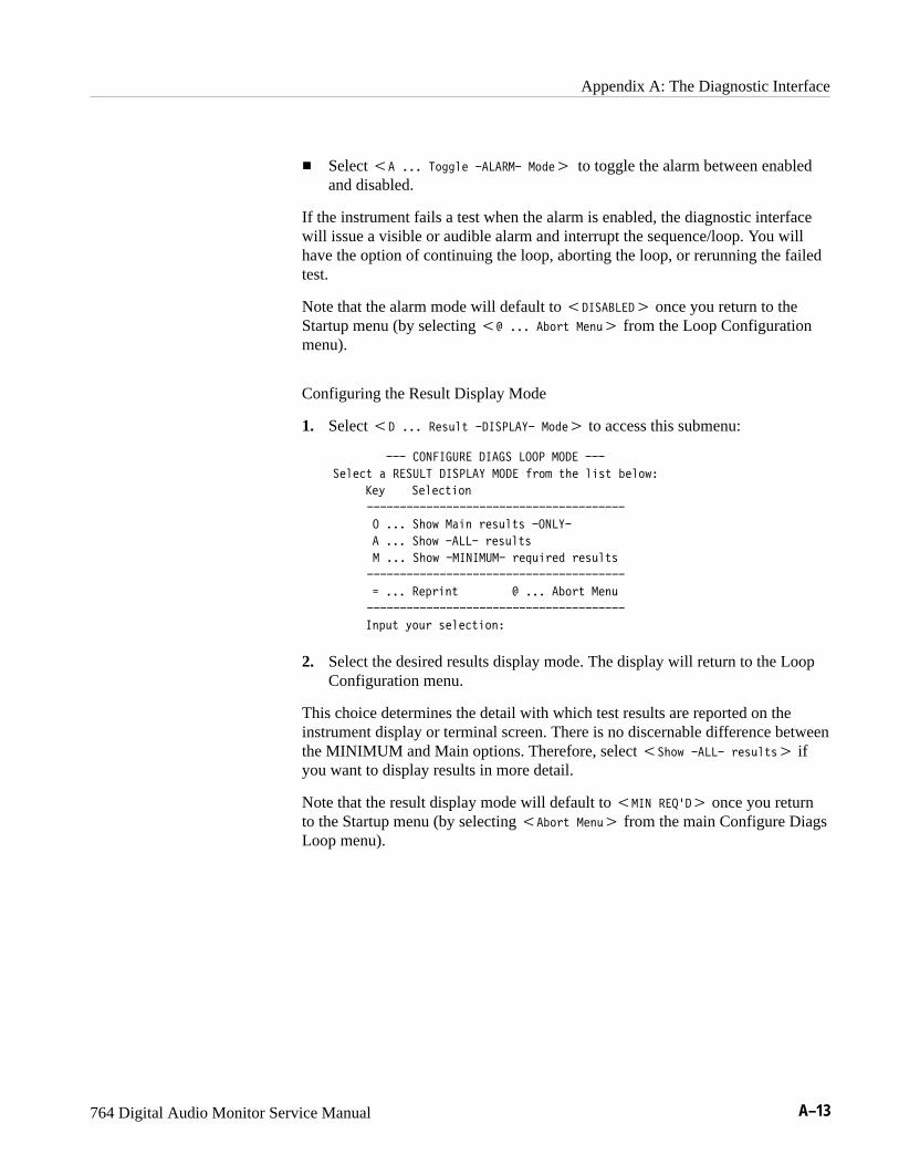
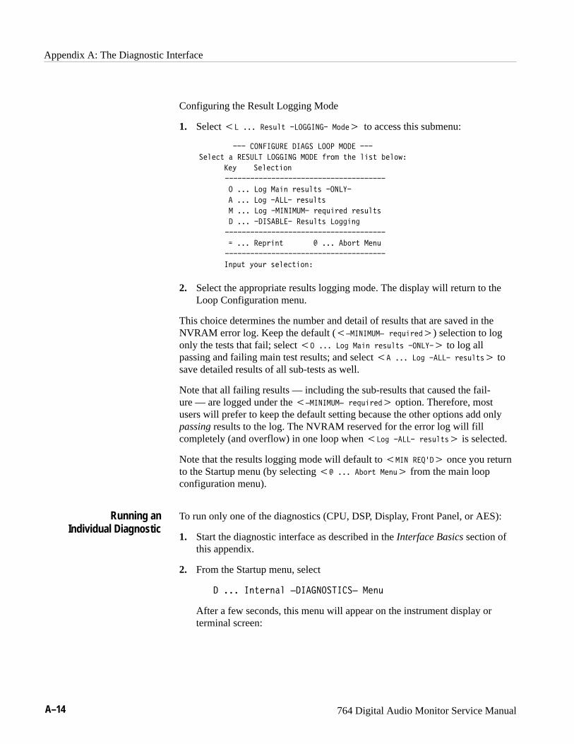
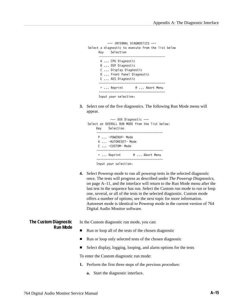
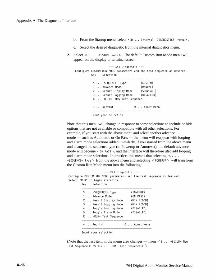
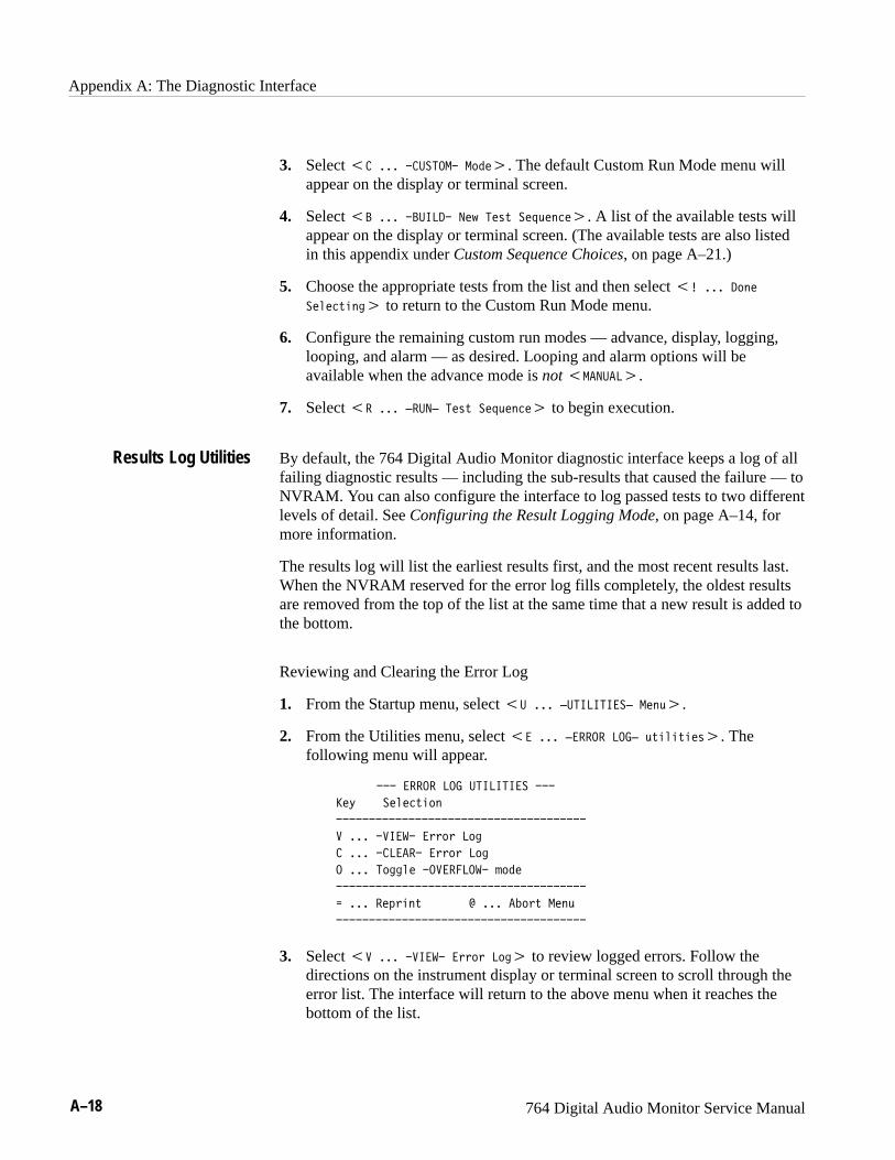
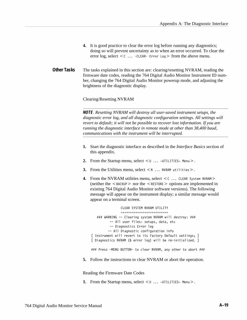


![Back Pressure Monitor - IOM P480922 (rev 1) · 6 Donaldson Back Pressure Monitor Manual ... [DECS] Serial No., install date, etc.) NOTE ... communication using console.](https://static.documents.pub/doc/80x56/5b4ada6d7f8b9a403d8c81b2/back-pressure-monitor-iom-p480922-rev-1-6-donaldson-back-pressure-monitor.jpg)


