SIPROTEC Distance Protection 7SA522 V4.70 Manual C53000-G1176-C155-7 Preface Contents Introduction 1 Functions 2 Mounting and Commissioning 3 Technical Data 4 Appendix A Literature Glossary Index
Transcript
SIPROTEC
Distance Protection7SA522
V4.70
Manual
I
F
M
T
A
L
G
I
C53000-G1176-C155-7
Preface
Contents
ntroduction 1unctions 2ounting and Commissioning 3
echnical Data 4ppendix Aiterature
lossary
ndex
NoteFor safety purposes, please note instructions and warnings in the Preface.
Disclaimer of liabilityWe have checked the text of this manual against the hardware and software described. However, deviations from the description cannot be completely ruled out, so that no liability can be accepted for any errors or omissions contained in the information given.The information given in this document is reviewed regularly and any necessary corrections will be included in subsequent editions. We appreciate any suggestions for improvement.We reserve the right to make technical improvements without notice.Document Version V04.70.01Release date 02.2011
Registered TrademarksSIPROTEC, SINAUT, SICAM and DIGSI are registered trademarks of Siemens AG. Other designations in this manual might be trade-marks whose use by third parties for their own purposes would in-fringe the rights of the owner.
Siemens Aktiengesellschaft Order no.: C53000-G1176-C155-7
Preface
Purpose of this Manual
This manual describes the functions, operation, installation, and commissioning of devices 7SA522. In partic-ular, one will find:
• Information regarding the configuration of the scope of the device and a description of the device functions and settings → Chapter 2;
• Instructions for Installation and Commissioning → Chapter 3;
• Compilation of the Technical Data → Chapter 4;
• As well as a compilation of the most significant data for advanced users → Appendix A.
General information with regard to design, configuration, and operation of SIPROTEC 4 devices are set out in the SIPROTEC 4 System Description /1/.
Target Audience
Protection engineers, commissioning engineers, personnel concerned with adjustment, checking, and service of selective protection equipment, automatic and control facilities, and personnel of electrical facilities and power plants.
Applicability of this Manual
This manual applies to: SIPROTEC 4 Distance Protection 7SA522; firmware version V4.70.
Indication of Conformity
This product complies with the directive of the Council of the European Communities on the approximation of the laws of the Member States relating to electromagnetic compatibility (EMC Council Directive 2004/108/EC) and concerning electrical equipment for use within specified voltage limits (Low-voltage directive 2006/95 EC).This conformity is proved by tests conducted by Siemens AG in accordance with the Council Directives in agreement with the generic standards EN61000-6-2 and EN 61000-6-4 for the EMC directive, and with the standard EN 60255-27 for the low-voltage directive. The device has been designed and produced for industrial use.The product conforms with the international standard of the series IEC 60255 and the German standard VDE 0435.
SIPROTEC, 7SA522, ManualC53000-G1176-C155-7, Release date 02.2011
3
Preface
Additional Support
Should further information on the System SIPROTEC 4 be desired or should particular problems arise which are not covered sufficiently for the purchaser's purpose, the matter should be referred to the local Siemens rep-resentative.
Our Customer Support Center provides a 24-hour service.
Enquiries regarding individual training courses should be addressed to our Training Center:
Siemens AG
Siemens Power Academy TD
Humboldt Street 59
90459 Nuremberg
Phone: +49 (911) 433-7005
Fax: +49 (911) 433-7929
Internet: www.siemens.com/power-academy-td
Additional Standards IEEE Std C37.90 (see Chapter 4, Technical Data")
SIPROTEC, 7SA522, ManualC53000-G1176-C155-7, Release date 02.2011
4
Preface
Safety Information
This manual does not constitute a complete index of all required safety measures for operation of the equip-ment (module, device), as special operational conditions may require additional measures. However, it com-prises important information that should be noted for purposes of personal safety as well as avoiding material damage. Information that is highlighted by means of a warning triangle and according to the degree of danger, is illustrated as follows.
DANGER!Danger indicates that death, severe personal injury or substantial material damage will result if proper precau-tions are not taken.
WARNING!indicates that death, severe personal injury or substantial property damage may result if proper precautions are not taken.
Caution!indicates that minor personal injury or property damage may result if proper precautions are not taken. This particularly applies to damage to or within the device itself and consequential damage thereof.
Note
indicates information on the device, handling of the device, or the respective part of the instruction manual which is important to be noted.
SIPROTEC, 7SA522, ManualC53000-G1176-C155-7, Release date 02.2011
5
Preface
WARNING!Qualified Personnel
Commissioning and operation of the equipment (module, device) as set out in this manual may only be carried out by qualified personnel. Qualified personnel in terms of the technical safety information as set out in this manual are persons who are authorized to commission, activate, to ground and to designate devices, systems and electrical circuits in accordance with the safety standards.
Use as prescribed
The operational equipment (device, module) may only be used for such applications as set out in the catalogue and the technical description, and only in combination with third-party equipment recommended or approved by Siemens.
The successful and safe operation of the device is dependent on proper handling, storage, installation, opera-tion, and maintenance.
When operating an electrical equipment, certain parts of the device are inevitably subject to dangerous voltage. Severe personal injury or property damage may result if the device is not handled properly.
Before any connections are made, the device must be grounded to the ground terminal.
All circuit components connected to the voltage supply may be subject to dangerous voltage.
Dangerous voltage may be present in the device even after the power supply voltage has been removed (ca-pacitors can still be charged).
Operational equipment with open circuited current transformer circuits may not be operated.
The limit values as specified in this manual or in the operating instructions may not be exceeded. This aspect must also be observed during testing and commissioning.
SIPROTEC, 7SA522, ManualC53000-G1176-C155-7, Release date 02.2011
6
Preface
Typographic and Symbol Conventions
The following text formats are used when literal information from the device or to the device appear in the text flow:
Parameter Names
Designators of configuration or function parameters which may appear word-for-word in the display of the device or on the screen of a personal computer (with operation software DIGSI), are marked in bold letters in monospace type style. The same applies to titles of menus.
1,234A
Parameter addresses have the same character style as parameter names. Parameter addresses contain the suffix A in the overview tables if the parameter can only be set in DIGSI via the option Display additional set-tings.
Parameter Options
Possible settings of text parameters, which may appear word-for-word in the display of the device or on the screen of a personal computer (with operation software DIGSI), are additionally written in italics. The same applies to the options of the menus.
„Messages“
Designators for information, which may be output by the relay or required from other devices or from the switch gear, are marked in a monospace type style in quotation marks.
Deviations may be permitted in drawings and tables when the type of designator can be obviously derived from the illustration.
The following symbols are used in drawings:
Device-internal logical input signal
Device-internal logical output signal
Internal input signal of an analog quantity
External binary input signal with number (binary input, input indication)
External binary output signal with number (example of a value indication)
External binary output signal with number (device indication) used as input signal
Example of a parameter switch designated FUNCTION with address 1234 and the possible settings ON and OFF
SIPROTEC, 7SA522, ManualC53000-G1176-C155-7, Release date 02.2011
7
Preface
Besides these, graphical symbols are used in accordance with IEC 60617-12 and IEC 60617-13 or similar. Some of the most frequently used are listed below:
■
Analog input values
AND-gate operation of input values
OR-gate operation of input values
Exclusive OR gate (antivalence): output is active, if only one of the inputs is active
Coincidence gate: output is active, if both inputs are active or inactive at the same time
Dynamic inputs (edge-triggered) above with positive, below with nega-tive edge
Formation of one analog output signal from a number of analog input signals
Limit stage with setting address and parameter designator (name)
Timer (pickup delay T, example adjustable) with setting address and parameter designator (name)
Timer (dropout delay T, example non-adjustable)
Dynamic triggered pulse timer T (monoflop)
Static memory (RS-flipflop) with setting input (S), resetting input (R), output (Q) and inverted output (Q)
SIPROTEC, 7SA522, ManualC53000-G1176-C155-7, Release date 02.2011
SIPROTEC, 7SA522, ManualC53000-G1176-C155-7, Release date 02.2011
17
Contents
SIPROTEC, 7SA522, ManualC53000-G1176-C155-7, Release date 02.2011
18
Introduction 1The SIPROTEC 4 7SA522 is introduced in this chapter. The device is presented in its application, characteris-tics, and functional scope.
1.1 Overall Operation 20
1.2 Application Scope 23
1.3 Characteristics 26
SIPROTEC, 7SA522, ManualC53000-G1176-C155-7, Release date 02.2011
19
Introduction1.1 Overall Operation
1.1 Overall Operation
The digital distance protection SIPROTEC 4 7SA522 is equipped with a powerful microprocessor system. All tasks, such as the acquisition of the measured quantities and the issuing of commands to circuit breakers, are processed in a completely digital way.. Figure 1-1 shows the basic structure of the 7SA522.
Analog Inputs
The measuring inputs (MI) convert the currents and voltages coming from the instrument transformers and adapt them to the level appropriate for the internal processing of the device. The device has 4 current and 4 voltage inputs. Three current inputs are provided for measurement of the phase currents, a further measuring input (I4) may be configured to measure the earth current (residual current from the current transformer star-point), the earth current of a parallel line (for parallel line compensation) or the star-point current of a power transformer (for earth fault direction determination).
Figure 1-1 Hardware structure of the digital Distance Protection 7SA522
SIPROTEC, 7SA522, ManualC53000-G1176-C155-7, Release date 02.2011
20
Introduction1.1 Overall Operation
A voltage measuring input is provided for each phase-earth voltage. A further voltage input (U4) may optionally be used to measure either the displacement voltage (e-n voltage), or the additiona voltage of synchronism and voltage check or any other voltage Ux (for overvoltage protection). The analog signals are then routed to the input amplifier group “IA”.
The input amplifier group IA provides high-resistance termination for the analog input quantities. It comprises filters that are optimized for measured value processing with regard to bandwidth and processing speed.
The AD analog digital converter group contains analog/digital converters and memory components for data transfer to the microcomputer system.
Microcomputer System
Apart from processing the measured values, the microcomputer system µC also executes the actual protection and control functions consisting of:
• Filtering and conditioning of the measured signals
• Continuous monitoring of the measured quantities
• Monitoring of the pickup conditions for the individual protection functions
• Monitoring of limit values and time sequences
• Control of signals for logical functions
• Reaching trip and close command decisions
• Recording of messages, fault data and fault values for analysis
• Administration of the operating system and its functions, e.g. data storage, realtime clock, communication, interfaces, etc.
The information is provided via output amplifier OA.
Binary Inputs and Outputs
Binary inputs from and outputs to the computer system are routed via the I/O modules (inputs and outputs). The computer system obtains information from the system (e.g remote resetting) or from the external equip-ment (e.g. blocking commands). Outputs are commands that are issued to the switching devices and messag-es for remote signalling of important events and states.
Front Elements
LEDs and an LC display provide information on the function of the device and indicate events, states and mea-sured values.
Integrated control and numeric keys in conjunction with the LCD facilitate local communication with the device. Thus, all information of the device, e.g. configuration and setting parameters, operating and fault messages, and measured values can be retrieved or changed (see also chapter 2 and SIPROTEC 4 System Description).
Devices with control functions also allow control of switchgear from the front panel.
SIPROTEC, 7SA522, ManualC53000-G1176-C155-7, Release date 02.2011
21
Introduction1.1 Overall Operation
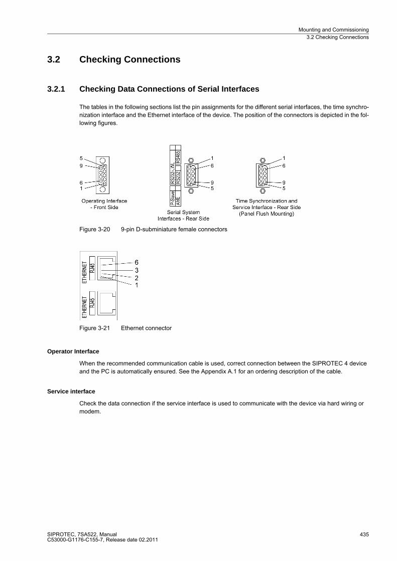
Serial Interfaces
Communication with a personal computer using the DIGSI software program is possible via the serial operator interface. This allows all device functions to be handled conveniently.
The serial service interface can also be used for communication with a personal computer using DIGSI. This port is especially well suited for a permanent connection of the devices to the PC or for operation via a modem.
All device data can be transmitted to a control center through the serial system interface. Various protocols and physical arrangements are available for this interface to suit a particular application.
An additional interface is provided for time synchronization of the internal clock through external synchroniza-tion sources.
Further communication protocols can be realized via additional interface modules.
Protection Data Interfaces (optional)
Depending on the version, there are one or two protection data interfaces available. Via these interfaces, the data for the teleprotection scheme and further information such as closing of the local circuit breaker and other externally coupled trip commands and binary information can be transmitted to other ends.
Power Supply
The functional units described are powered by a power supply, PS, with adequate power in the different voltage levels. Brief supply voltage dips which may occur during short circuits in the auxiliary voltage supply of the sub-station, are usually bridged by a capacitor (see also Technical Data, Section 4.1).
SIPROTEC, 7SA522, ManualC53000-G1176-C155-7, Release date 02.2011
22
Introduction1.2 Application Scope
1.2 Application Scope
The digital distance protection SIPROTEC 4 7SA522 is a selective and extremely fast protection for overhead lines and cables with single- and multi-ended infeeds in radial, ring or any type of meshed systems at any voltage levels. The network neutral can be earthed, compensated or isolated.
The device incorporates the functions which are normally required for the protection of an overhead line feeder and is therefore capable of universal application. It may also be applied as time-graded back-up protection to all types of comparison protection schemes used on lines, transformers, generators, motors and busbars at all voltage levels.
The devices located at the ends of the protected zone exchange measuring information via teleprotection func-tions with conventional connections (contacts) or via optional protection data interfaces using dedicated com-munication links (usually fibre optic cables) or a communication network. If the 7SA522 devices are equipped with one protection data interface, they can be used for a protection object with two ends. Lines with three ends (teed feeders) require at least one device with two protection data interfaces.
Protection Functions
The basic function of the device is the recognition of the distance to the fault with distance protection measure-ment. In particular for complex multiphase faults, the distance measurement is designed with multiple measur-ing elements. Different pickup schemes enable adaptation to system conditions and the user's protection phi-losophy. The network neutral can be isolated, compensated or earthed (with or without earth current limiting). The use on long, heavily-loaded lines is possible with or without series compensation.
The distance protection may be supplemented by teleprotection using various signal transmission schemes (for fast tripping on 100 % of the line length). In addition, an earth fault protection for high resistance earth faults (ordering option) is available. It may be directional or non-directional and may also be incorporated in signal transmission schemes. On lines with weak or no infeed at one line end, it is possible to achieve fast tripping at both line ends by means of the signal transmission schemes. When switching onto a fault along the line, an undelayed trip signal can be emitted.
In the event of a failure of the measured voltages due to a fault in the secondary circuits (e.g. trip of the voltage transformer mcb or a blown fuse), the device can automatically revert to emergency operation with an integrat-ed overcurrent protection, until such time as the measured voltage returns. Alternatively, the time delayed over-current protection may be used as back-up time delayed overcurrent protection, i.e. it functions independently and in parallel to the distance protection.
Depending on the version ordered, most short-circuit protection functions may also trip single-pole. They may operate in co-operation with an integrated automatic reclosure (optional ordering feature) with which single-pole, three-pole or single- and three-pole automatic reclosures as well as multi-shot automatic reclosure are possible on overhead lines. Before reclosure after three-pole tripping, the valid status for reclosure can be checked by the device through voltage and/or synchronism check (optional ordering feature). It is possible to connect an external automatic reclosure and/or synchronism check, as well as double protection with one or two automatic reclosure functions.
Apart from the mentioned fault protection functions, additional protection functions are possible, such as multi-stage overvoltage, undervoltage and frequency protection, circuit breaker failure protection and protection against effects of power swings (simultaneously active as power swing blocking for the distance protection).To assist in localizing the fault as fast as possible after an incident, a fault location with optional load compensation for improved accuracy is incorporated in the device.
SIPROTEC, 7SA522, ManualC53000-G1176-C155-7, Release date 02.2011
23
Introduction1.2 Application Scope
Digital Transmission of Protection Data (optional)
If the distance protection is to be complemented by digital teleprotection schemes, the data required for this purpose can be transmitted via the protection data interface by employing a digital communication link. Com-munication via the protection data interfaces can be used for transmitting additional information, e.g. measured values, binary commands and other information can be transmitted.
With more than two devices (= ends of the protected object) and when using optional protection data interfaces, the communication can be built up as a ring. This enables a redundant operation in case a communication line fails. The devices will automatically find the remaining healthy communication lines. But even with two ends, communication lines can be doubled to create redundancies.
Control Functions
The device is equipped with control functions which operate, close and open, switchgear devices via control keys, the system interface, binary inputs and a PC with DIGSI software. The status of the primary equipment can be transmitted to the device via auxiliary contacts connected to binary inputs. The present status (or posi-tion) of the primary equipment can be displayed on the device, and used for interlocking or plausibility monitor-ing. The number of the devices to be switched is limited by the binary inputs and outputs available in the device or the binary inputs and outputs allocated for the switch position feedbacks. Depending on the mode of opera-tion, one binary input (single point indication) or two binary inputs (double point indication) can be used. The capability of switching primary equipment can be restricted by appropriate settings for the switching authority (remote or local), and by the operating mode (interlocked/non-interlocked, with or without password validation). Interlocking conditions for switching (e.g. switchgear interlocking) can be established using the integrated user-defined logic.
Indications and Measured Values; Fault Recording
The operational indications provide information about conditions in the power system and the device. Measure-ment quantities and values that are calculated can be displayed locally and communicated via the serial inter-faces.
Device messages can be assigned to a number of LEDs on the front panel (programmable), can be externally processed via output contacts (programmable), linked with user-definable logic functions and/or issued via serial interfaces (see Communication below).
During a fault (system fault) important events and changes in conditions are saved in fault logs. Instantaneous fault values are also saved in the device and may be analysed at a later time.
SIPROTEC, 7SA522, ManualC53000-G1176-C155-7, Release date 02.2011
24
Introduction1.2 Application Scope
Communication
Serial interfaces are available for the communication with operating, control and memory systems.
A 9-pin DSUB socket on the front panel is used for local communication with a personal computer. By means of the SIPROTEC 4 operating software DIGSI, all operational and evaluation tasks can be executed via this operator interface, such as specifying and modifying configuration parameters and settings, configuring user-specific logic functions, retrieving operational and fault messages and measured values, reading out and dis-playing fault recordings, inquiring device conditions and measured values, issuing control commands.
To establish an extensive communication with other digital operating, control and memory components the device may be provided with further interfaces depending on the order variant.
The service interface can be operated via the RS232 or RS485 interface and also allows communication via modem. For this reason, remote operation is possible via PC and the DIGSI operating software, e.g. to operate several devices via a central PC.
The system interface is used for central communication between the device and a control center. It can be op-erated through the RS232, the RS485 or the FO port. Several standardized protocols are available for data transmission. An EN 100 module allows integrating the devices into 100 MBit Ethernet communication net-works of the process control and automation system, using IEC 61850 protocols. In parallel to the link with the process control and automation system, this interface can also handle DIGSI communication and inter-relay communication using GOOSE messaging.
Another interface is provided for the time synchronization of the internal clock via external synchronization sources (IRIG-B or DCF77).
Other interfaces provide for communication between the devices at the ends of the protected object. These protection data interfaces have been mentioned above in the protection functions.
The operator and service interface allow operation of the device remotely or locally, using a standard browser. This can be used during commissioning, maintenance and also during operation of the devices at all ends of the protected object using a communication network. For this application, a special tool, the „WEB Monitor“, is provided. This tool has been optimized for distance protection.
SIPROTEC, 7SA522, ManualC53000-G1176-C155-7, Release date 02.2011
25
Introduction1.3 Characteristics
1.3 Characteristics
General Features
• Powerful 32-bit microprocessor system
• Complete digital processing of measured values and control, from the sampling and digitizing of the measure quantities up to the closing and tripping commands to the circuit breakers
• Complete galvanic separation and interference immunity of the internal processing circuits from the mea-surement, control, and power supply circuits by analog input transducers, binary inputs and outputs and the DC/DC or AC/DC converters
• Complete scope of functions which is normally required for the protection of a line feeder
• digital protection data transmission, may be used for teleprotection with permanent monitoring of distur-bance, fault or transfer time deviations in the communication network with automatic runtime re-adjustment
• Distance protection system realizable for up to three ends
• Simple device operation using the integrated operator panel or a connected personal computer with operator guidance
• Storage of fault indications and instantaneous values for fault recording
Distance Protection
• Protection for all types of faults in systems with earthed, compensated or isolated starpoint
• Selectable polygonal tripping characteristic or MHO characteristic;
• reliable differentiation between load and short-circuit conditions also in long, high-loaded lines
• high-sensitivity in the case of a system with week in-feed, extreme stability against load jumps and power swings
• optimum adaptation to the line parameters by means of the polygonal tripping characteristic with diverse configuration parameters and„load trapezoid“ (elimination of the possible load impedance)
• 6 measuring systems for each distance zone
• 7 distance zones, selectable as forward, reverse or non-directional, one of which may be used as a con-trolled overreach zone
• 10 time stages for the distance zones
• Direction determination (with polygon) or polarisation (with MHO-circle) is done with unfaulted loop (quadra-ture) voltages and voltage memory, thereby achieving unlimited directional sensitivity, which is not affected by capacitive voltage transformer transients;
• suitable for lines with series compensation
• insensitive to current transformer saturation
• compensation against the influence of a parallel line can be implemented
• shortest tripping time is approx. 17 ms (for fN = 50 Hz) or 15 ms (for fN = 60 Hz)
• phase segregated tripping (in conjunction with single-pole or single- and three-pole auto-reclosure)
• non-delayed tripping following switch onto fault is possible
• seperate earth impedance compensation setting pair (RE/RL and XE/XL) for zone 1 and other zones
SIPROTEC, 7SA522, ManualC53000-G1176-C155-7, Release date 02.2011
26
Introduction1.3 Characteristics
Power Swing Supplement (optional)
• Power swing detection with dZ/dt measurement from three measuring systems
• Power swing detection up to 10 Hz swing frequency
• Remains in service also during single-pole dead times
• settable power swing programs
• prevention of undesired tripping by the distance protection during power swings
• Tripping for out-of-step conditions can be configured
Teleprotection Supplement
• Different schemes which may be set:
• Permissive Underreach Transfer Trip = PUTT (via a separately settable overreach zone);
• Comparison schemes (Permissive Overreach Transfer Trip = POTT or blocking schemes, with separate overreach zone);
• suitable for lines with two or three ends
• Phase segregated transmission possible in lines with two ends
• Optional signal exchange of the devices via dedicated communication connections (in general optical fibres) or a communication network, in this case a phase segregated transmission with two or three line ends and continuous monitoring of the communication paths and the signal propagation delay with automatic re-ad-justment takes place
Earth Fault Protection (optional)
• Time overcurrent protection with a maximum of three definite time stages (DT) and one inverse time stage (IDMT) for high resistance earth faults in earthed systems
• For inverse-time overcurrent protection a selection from various characteristics based on several standards is possible
• The inverse time stage can additionally be set as fourth definite time stage
• High-sensitivity (depending on the version from 3 mA is possible)
• Phase current restraint against error currents due to tolerances in the current transformer measurement
• Second harmonic inrush restraint
• Optional earth fault protection with an inverse tripping time dependent on zero sequence voltage or zero se-quence power
• Each stage can be set to be non-directional or directional in the forward or reverse direction
• Single-pole tripping enabled by integrated phase selector
• Direction determination with automatic selection of the larger of zero sequence voltage or negative se-quence voltage (U0, IY or U2), with zero sequence system quantities (I0, U0), with zero sequence current and transformer starpoint current (I0, IY), with negative sequence system quantities (I2, U2) or with zero sequence power (3I0 · 3U0)
• One or more stages may function in conjunction with a signal transmission supplement; also suited for lines with three ends
• Instantaneous tripping by any stage when switching onto a fault
SIPROTEC, 7SA522, ManualC53000-G1176-C155-7, Release date 02.2011
27
Introduction1.3 Characteristics
Transmission of Information (only with Digital Protection Data Transmission)
• Transmission of the measured values from all ends of the protected object
• Transmission of four commands to all ends
• Transmission of twenty-four additional binary signals to all ends.
Tripping at Line Ends with no or Weak Infeed
• Possible in conjunction with teleprotection schemes
• Allows fast tripping at both line ends, even if there is no or only weak infeed available at one line end
• Phase segregated tripping and single-pole automatic reclosure is possible (version with single-phase trip-ping)
External Direct and Remote Tripping
• Tripping at the local line end from an external device via a binary input
• Tripping of the remote line end by internal protection functions or an external device via a binary input (with teleprotection)
Time Overcurrent Protection
• Optional as emergency function in the case of measured voltage failure, or as backup function independent of the measured voltage
• Two definite time stages (DT) and one inverse time stage (IDMT), each for phase currents and earth current
• For inverse-time overcurrent protection select from various characteristics based on several standards
• Blocking capability e.g. for reverse interlocking with any stage
• Instantaneous tripping by any stage when switching onto a fault
• Additional stage, e.g. stub protection, for fast tripping of faults between the current transformer and line iso-lator (when the isolator switching status feedback is available); particularly well suited to substations with 11/2 circuit breaker arrangements.
• Fast tripping for all faults on total line length
• Selectable for manual closure or following each closure of the circuit breaker
• with integrated line energisation detection
Automatic Reclosure Function (optional)
• For reclosure after 1-pole, 3-pole or 1-pole and 3-pole tripping
• Single or multiple reclosure (up to eight reclosure attempts)
• With separate action time setting for the first 4 reclose attempts, optionally without action times
• With separate dead times after 1-pole and 3-pole tripping, separate for the first four reclosure attempts
• Controlled optionally by protection pickup with separate dead times after 1-pole , 2-pole or 3-pole pickup
• Optionally with adaptive dead time, reduced dead time and dead line check
SIPROTEC, 7SA522, ManualC53000-G1176-C155-7, Release date 02.2011
28
Introduction1.3 Characteristics
Synchronism and Voltage Check (optional)
• Verification of the synchronous conditions before reclosing after three-pole tripping
• Fast measurement of the voltage difference Udiff, the phase angle difference ϕdiff and the frequency differ-ence fdiff
• Alternatively, check of the de-energized state before reclosing
• Closing at asynchronous system conditions with consideration of the CB closing time to scieve system re-connection when voltages are in phase
• Settable minimum and maximum voltage
• Verification of the synchronous conditions or de-energized state before manual closing of the circuit breaker is possible with separate setting thresholds and states
• Phase angle compensation for voltage measurement behind a transformer
• Measuring voltages optionally phase-phase or phase-earth
Voltage Protection (optional)
• Overvoltage and undervoltage detection with different stages
• Two overvoltage stages for the phase-earth voltages
• Two overvoltage stages for the phase-phase voltages
• Two overvoltage stages for the positive sequence voltage, optionally with compounding
• Two overvoltage stages for the negative sequence voltage
• Two overvoltage stages for the zero sequence voltage or any other single-phase voltage
• Settable dropout to pickup ratios
• Two undervoltage stages for the phase-earth voltages
• Two undervoltage stages for the phase-phase voltages
• Two undervoltage stages for the positive sequence voltage
• Settable current criterion for undervoltage protection functions
Frequency Protection (optional)
• Monitoring on underfrequency (f<) and/or overfrequency (f>) with 4 frequency limits and delay times that are independently adjustable
• Very insensitive to harmonics and abrupt phase angle changes
• Large frequency range (approx. 25 Hz to 70 Hz)
Fault Location
• Initiated by trip command or dropout of the pickup;
• Computation of the distance to fault with dedicated measured value registers
• Fault location output in Ohm, kilometers or miles and % of line length
• Parallel line compensation can be selected
• Taking into consideration the load current in case of single-phase earth faults fed from both sides (config-urable)
• Output of the fault location also possible in BCD code (depending on the order variant).
SIPROTEC, 7SA522, ManualC53000-G1176-C155-7, Release date 02.2011
29
Introduction1.3 Characteristics
Circuit Breaker Failure Protection (optional)
• With definite time current stages for monitoring the current flow through every pole of the circuit breaker
• Separate pickup thresholds for phase and earth currents
• Independent timers for single-pole and three-pole tripping;
• Start by trip command of every internal protection function
• Start by external trip functions possible
• Single-stage or two-stage
• Short dropout and overshoot times
User-defined Logic Functions (CFC)
• Freely programmable combination of internal and external signals for the implementation of user-defined logic functions
• All typical logic functions
• Time delays and limit value inquiries
Commissioning; operation (only with digital transmission of protection data)
• Display of magnitude and phase angle of local and remote measured values
• Display of measured values of the communication link, such as transmission delay and availability
Command Processing
• Switchgear can be switched on and off manually via local control keys, the programmable function keys on the front panel, via the system interface (e.g. by SICAM or LSA), or via the operator interface (using a per-sonal computer and the operating software DIGSI)
• Feedback on switching states via the circuit breaker auxiliary contacts (for commands with feedback)
• Monitoring of the circuit breaker position and of the interlocking conditions for switching operations.
Monitoring Functions
• Availability of the device is greatly increased because of self-monitoring of the internal measurement circuits, power supply, hardware and software
• Monitoring of the current and voltage transformer secondary circuits by means of summation and symmetry checks
• Trip circuit supervision
• Checking for the load impedance, the measured direction and the phase sequence
• Monitoring of the signal transmission of the optional digital communication path
SIPROTEC, 7SA522, ManualC53000-G1176-C155-7, Release date 02.2011
30
Introduction1.3 Characteristics
Additional Functions
• Battery buffered real time clock, which may be synchronised via a synchronisation signal (e.g. DCF77, IRIGB via satellite receiver), binary input or system interface
• Continuous calculation and display of measured quantities on the front display. Indication of measured values of the remote end or of all ends (for devices with protection data interfaces)
• Fault event memory (trip log) for the last eight network faults (faults in the power system), with real time stamps
• Fault recording and data transfer for fault recording for a maximum time range of 15seconds
• Switching statistics: Counting of the trip and close commands issued by the device, as well as recording of the fault current data and accumulation of the interrupted fault currents
• Communication with central control and memory components possible via serial interfaces (depending on the options ordered), optionally via RS232, RS485, modem connection or fibre optic cable
• Commissioning aids such as connection and direction checks as well as circuit breaker test functions
• The WEB monitor (installed on a PC or a laptop) widely supports the testing and commissioning procedure by providing a graphic presentation of the protection system with phasor diagrams. All currents and voltages from all ends of the system are displayed on the screen provided that the devices are connected via protec-tion data interfaces.
■
SIPROTEC, 7SA522, ManualC53000-G1176-C155-7, Release date 02.2011
31
Introduction1.3 Characteristics
SIPROTEC, 7SA522, ManualC53000-G1176-C155-7, Release date 02.2011
32
Functions 2This chapter describes the individual functions of the SIPROTEC 4 device 7SA522. It shows the setting pos-sibilities for each function in maximum configuration. Guidelines for establishing setting values and, where re-quired, formulae are given.
Based on the following information, it can also be determined which of the provided functions should be used.
2.1 General 34
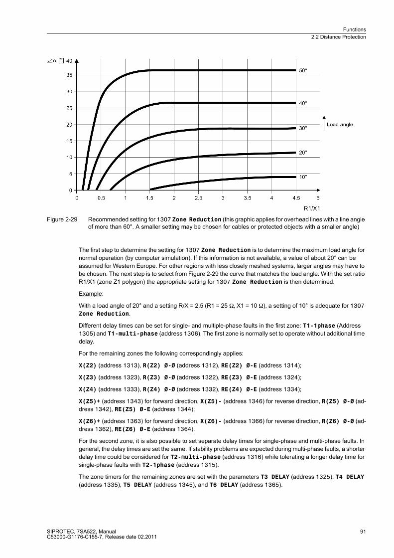
2.2 Distance Protection 59
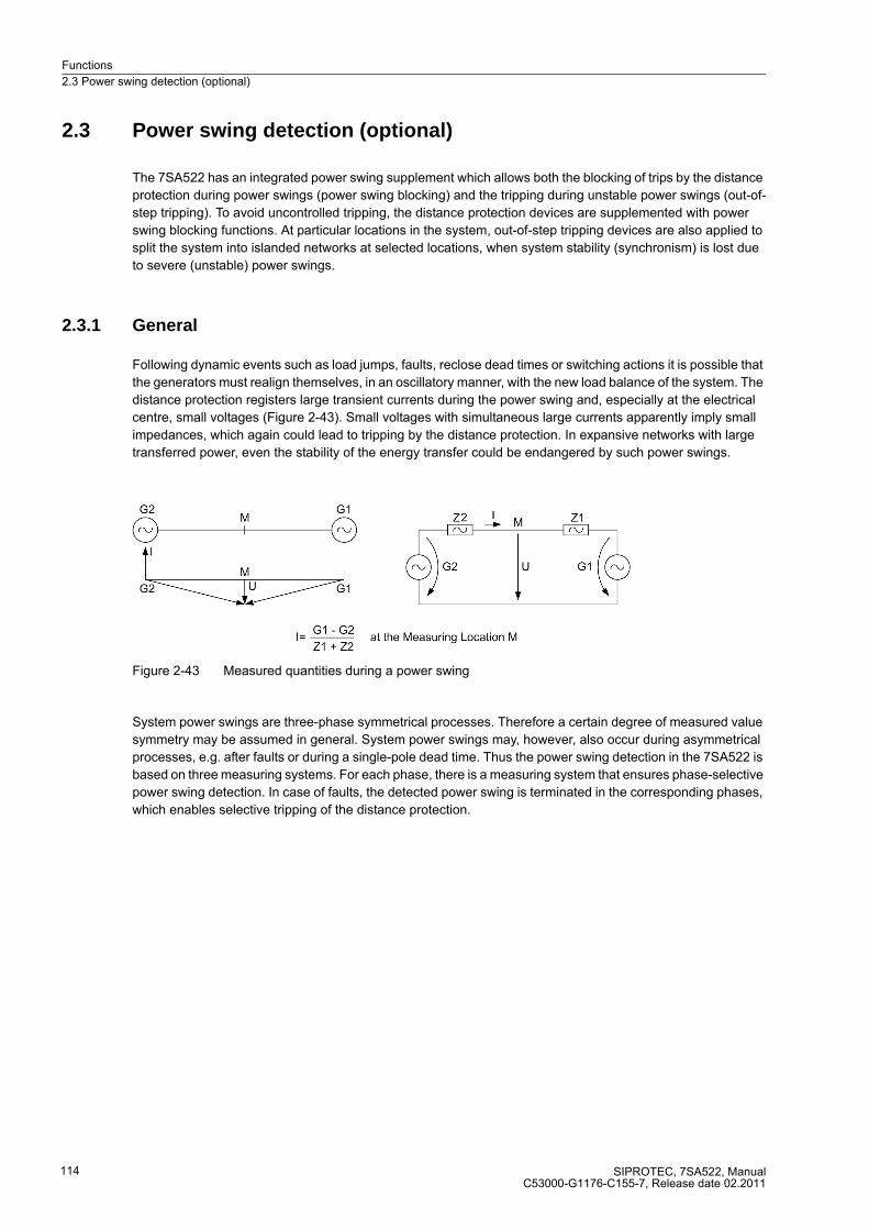
2.3 Power swing detection (optional) 114
2.4 Protection data interfaces and communication topology (optional) 120
2.5 Remote signals via protection data interface (optional) 129
2.6 Teleprotection for distance protection 132
2.7 Earth fault overcurrent protection in earthed systems (optional) 156
2.8 Teleprotection for earth fault overcurrent protection (optional) 187
2.20 Function Control and Circuit Breaker Test 351
2.21 Auxiliary Functions 372
2.22 Command Processing 394
SIPROTEC, 7SA522, ManualC53000-G1176-C155-7, Release date 02.2011
33
Functions2.1 General
2.1 General
A few seconds after the device is switched on, the initial display appears in the LCD.
Configuration settings can be entered by using a PC and the DIGSI operating software and transferred via the operator interface on the front panel of the device or via the service interface. The procedure is described in detail in the SIPROTEC 4 System Description. Entry of password no. 7 (parameter set) is required to modify configuration settings. Without the password, the settings may be read, but may not be modified and transmit-ted to the device.
The function parameters, i.e. function options, threshold values, etc., can be changed via the front panel of the device, or via the operator or service interface from a personal computer using DIGSI. The level 5 password (individual parameters) is required.
2.1.1 Functional Scope
2.1.1.1 Configuration of the Scope of Functions
The 7SA522 device contains a series of protection and additional functions. The hardware and firmware is de-signed for this scope of functions. Additionally, the command functions can be matched to the system condi-tions. Furthermore, individual functions may be enabled or disabled during configuration, or interaction between functions may be adjusted.
Example for the configuration of scope of functions:
A substation has feeders with overhead lines and transformers. Fault location is to be performed on the over-head lines only. In the devices for the transformer feeders this function is therefore set to „Disabled“.
The available protection functions and additional functions can be configured as Enabled or Disabled. For some functions, a choice between several options is possible which are described below.
Functions configured as Disabled are not processed by the 7SA522. There are no indications, and corre-sponding settings (functions, limit values) are not displayed during setting.
Note
The functions and default settings available depend on the device version ordered.
2.1.1.2 Setting Notes
Configuring the functional scope
The scope of functions with the available options is set in the Functional Scope dialog box to match plant re-quirements.
Most settings are self-explanatory. The special cases are described below:
SIPROTEC, 7SA522, ManualC53000-G1176-C155-7, Release date 02.2011
34
Functions2.1 General
Special Cases
For communication of the protection signals, each device may feature one or two protection data interfaces (depending on the ordered version). Determine at address 145 whether to use protection data interface 1 with setting STATE PROT I 1 or interface 2 at address 146 with setting STATE PROT I 2. A protected object with two ends requires at least one protection data interface for each relay. If there are more ends, it must be ensured that all associated devices are connected directly or indirectly (via other devices). Subsection 2.4 „Pro-tection Data Topology“ provides more information.
If use of the setting group changeover function is desired, address 103 Grp Chge OPTION should be set to Enabled. In this case, up to four different groups of settings may be changed quickly and easily during device operation (see also Section 2.1.3). With the setting Disabled only one parameter group is available.
Address 110 Trip mode is only valid for devices that can trip single-pole or three-pole. Set 1-/3pole to enable also single-pole tripping, i.e. if you want to utilise single-pole or single-pole/three-pole automatic reclo-sure. This requires that an internal automatic reclosure function exists or that an external reclosing device is used. Furthermore, the circuit breaker must be capable of single-pole tripping.
Note
If you have changed address 110, save your changes first via OK and reopen the dialog box since the other setting options depend on the selection in address 110.
Depending on the distance protection model, you can select the tripping characteristic. This setting is made in address 112 for the phase-phase measuring units Phase Distance and in address 113 for the phase-earth measuring units Earth Distance. You can select between the polygonal tripping characteristic Quadrilateral and the MHO characteristic. Sections 2.2.3 and 2.2.2 provide a detailed overview of the char-acteristics and measurement methods. The two adresses can be set seperately and differently. If the device is to be used only for phase-earth loops or only for phase-phase loops, set the function that is not required to Disabled. If only one of the characteristic options is available in the device, the relevant setting options are hidden.
To complement the distance protection by teleprotection schemes, you can select the desired scheme at address 121 Teleprot. Dist.. You can select the underreach transfer trip with overreach zone PUTT (Z1B), the teleprotection schemePOTT, the unblocking scheme UNBLOCKING and the blocking scheme BLOCKING. If the device features a protection data interface for communication via digital transmission lines, set SIGNALv.ProtInt here. The procedures are described in detail in Section 2.2.1. If you do not want to use teleprotection in conjunction with distance protection, set Disabled.
If a pickup of zone Z1 of the distance protection shall be possible only after exceeding an additional current threshold value, set the parameter 119 Iph>(Z1) to Enabled. Select the setting Disabled if the additional threshold value is not required.
The power swing supplement (see also Subsection 2.3) is activated by setting address 120 Power Swing = Enabled.
With address 125 Weak Infeed you can select a supplement to the teleprotection schemes. Set Enabled to apply the classic scheme for echo and weak infeed tripping. The setting Logic no. 2 switches this function to the french specification. This setting is available in the device variants for the region France (only version 7SA522*-**D** or 10th digit of order number = D).
At address 126 Back-Up O/C you can set the characteristic group that the time overcurrent protection uses for operation. In addition to the definite time overcurrent protection, you can configure an inverse time overcur-rent protection depending on the ordered version. The latter operates either according to an IEC characteristic (TOC IEC) or an ANSI characteristic (TOC ANSI). The various characteristic curves are illustrated in the Tech-nical Data. With the device version for the region Germany (10th digit of ordering code = A), the third definite time overcurrent stage is only availabe if the setting TOC IEC /w 3ST is active. You can also disable the time overcurrent protection (Disabled).
SIPROTEC, 7SA522, ManualC53000-G1176-C155-7, Release date 02.2011
35
Functions2.1 General
At address 131 Earth Fault O/C you can set the characteristic group which the earth fault protection uses for operation. In addition to the definite time overcurrent protection, which covers up to three phases, an inverse-time earth fault protection function may be configured depending on the ordered version. The latter op-erates either according to an IEC characteristic (TOC IEC) or an ANSI characteristic (TOC ANSI) or according to a logarithmic-inverse characteristic (TOC Logarithm.). If an inverse-time characteristic is not required, the stage usually designated „inverse time“ can be used as the fourth definite time stage (Definite Time). Al-ternatively, it is possible to select an earth fault protection with inverse-time characteristic U0 inverse (only for region Germany, 10th digit of the ordering code = A) or a zero sequence power protection Sr inverse (only for region France, 10th digit of ordering code = D). For the characteristics please refer to the Technical Data. You can also disable the earth fault protection (Disabled).
When using the earth fault protection, it can be complemented by teleprotection schemes. Select the desired scheme at address 132 Teleprot. E/F. You can select the direction comparison scheme Dir.Comp.Pickup, the unblocking scheme UNBLOCKING and the blocking scheme BLOCKING. The proce-dures are described in detail in Section 2.8. If the device features a protection data interface for communication via a digital link, set SIGNALv.ProtInt here. If you do not want to use teleprotection in conjunction with earth fault protection set Disabled.
Address 145 P. INTERFACE 1 and, where required, address 146 STATE PROT I 2 are also valid for com-munication of the teleprotection for earth fault protection via teleprotection interface, as described above.
If the device features an automatic reclosing function, address 133 and 134 are of importance. Automatic re-closure is only permitted for overhead lines. It must not be used in any other case. If the protected object con-sists of a combination of overhead lines and other equipment (e.g. overhead line in unit with a transformer or overhead line/cable), reclosure is only permissible if it can be ensured that it can only take place in the event of a fault on the overhead line. If no automatic reclosing function is desired for the feeder at which 7SA522 op-erates, or if an external device is used for reclosure, set address 133 Auto Reclose to Disabled.
Otherwise set the number of desired reclosing attempts there. You can select 1 AR-cycle to 8 AR-cycles. You can also set ADT (adaptive dead times); in this case the behaviour of the automatic reclosure function is determined by the cycles of the remote end. The number of cycles must however be configured at least in one of the line ends which must have a reliable infeed. The other end — or other ends, if there are more than two line ends — may operate with adaptive dead time. Section 2.13 provides detailed information on this topic.
The AR control mode at address 134 allows a total of four options. On the one hand, it can be determined whether the auto reclose cycles are carried out according to the fault type detected by the pickup of the starting protection function(s) (only for three-pole tripping) or according to the type of trip command. On the other hand, the automatic reclosure function can be operated with or without action time.
The setting Trip with T-action / Trip without T-action ... (default setting = Trip with T-action ... ) is preferred if single-pole or single-pole/three-pole auto reclose cycles are provided for and possible. In this case, different dead times (for every AR cycle) are possible after single-pole tripping and after three-pole trip-ping. The tripping protection function determines the type of tripping: Single-pole or three-pole. The dead time is controlled in dependence on this.
The setting Pickup with T-action / Pickup without T-action ... ... (Pickup with T-action ...) is only possible and visible if only three-pole tripping is desired. This is the case when either the ordering number of the device model indicates that it is only suited for three-pole tripping, or when only three-pole trip-ping is configured (address 110 Trip mode = 3pole only, see above). In this case, different dead times can be set for the auto reclose cycles following 1-, 2- and 3-phase faults. The decisive factor here is the pickup situation of the protection functions at the instant the trip command disappears. This operating mode enables making the dead times dependent on the type of fault also for three-pole reclosure cycles. Tripping is always three-pole.
The setting Trip with T-action with action time) provides an action time for each auto-reclose cycle. The action time is started by a general pickup of all protection functions. If there is no trip command yet when the action time has expired, the corresponding automatic reclosure cycle cannot be executed. Section 2.13 pro-vides detailed information on this topic. This setting is recommended for time-graded protection. If the protec-tion function which is to operate with automatic reclosure, does not have a general pickup signal for starting the action times, select Trip without T-action... (without action time).
SIPROTEC, 7SA522, ManualC53000-G1176-C155-7, Release date 02.2011
36
Functions2.1 General
Address 137 U/O VOLTAGE allows activating the voltage protection function with a variety of undervoltage and overvoltage protection stages. In particular, the overvoltage protection with the positive sequence system of the measuring voltages provides the option to calculate the voltage at the other, remote line end via integrated com-pounding. This is particularly useful for long transmission lines where no-load or low-load conditions prevail and an overvoltage at the other line end (Ferranti effect) is to cause tripping of the local circuit breaker. In this case set address 137 U/O VOLTAGE to Enabl. w. comp. (enabled with compounding). Do not use compounding on lines with series capacitors!
For the fault location you can determine at address 138 Fault Locator, in addition to Enabled and Disabled, that the fault distance is output in BCD code (4 bit units, 4 bit tens and 1 bit hundreds and „data valid“) via binary outputs (with BCD-output). A corresponding number of output relays (No. 1143 to 1152) must be made available and allocated for this purpose.
For the trip circuit supervision set at address 140 Trip Cir. Sup. the number of trip circuits to be monitored: 1 trip circuit, 2 trip circuits or 3 trip circuits, unless you omit it (Disabled).
SIPROTEC, 7SA522, ManualC53000-G1176-C155-7, Release date 02.2011
38
Functions2.1 General
2.1.2 Power System Data 1
The device requires some plant and power system data in order to be able to adapt its functions accordingly, depending on the actual application. The data required include for instance rated data of the substation and the measuring transformers, polarity and connection of the measured quantities, if necessary features of the circuit breakers, and others. Furthermore, there are several function parameters associated with several functions rather than one specific protection, control or monitoring function. The Power System Data 1 can only be changed from a PC running DIGSI and are discussed in this section.
2.1.2.1 Setting Notes
General
In DIGSI double-click on Settings to display the relevant selection. A dialog box with the tabs Transformers, Power System and Breaker will open under Power System Data 1 in which you can configure the individual parameters. The following subsections are structured in the same way.
Current Transformer Polarity
In address 201 CT Starpoint, the polarity of the wye-connected current transformers is specified (the fol-lowing figure also goes for only two current transformers). The setting determines the measuring direction of the device (forward = line direction). A change in this setting also results in a polarity reversal of the earth current inputs IE or IEE.
Figure 2-1 Polarity of current transformers
Nominal Values of the Transformers
In addresses 203 Unom PRIMARY and 204 Unom SECONDARY the device obtains information on the primary and secondary rated voltage (phase-to-phase voltage) of the voltage transformers; in address 205 CT PRIMARY and 206 CT SECONDARY the primary and secondary rated current transformers are set.
It is important to ensure that the secondary CT nominal current matches the rated current of the device, other-wise the device will be blocked. The nominal current is set with jumpers on the measuring module (see 3.1.2).
Correct entry of the primary data is a prerequisite for the correct computation of operational measured values with primary magnitude. If the settings of the device are performed with primary values using DIGSI, these primary data are an indispensable requirement for the correct function of the device.
SIPROTEC, 7SA522, ManualC53000-G1176-C155-7, Release date 02.2011
39
Functions2.1 General
Voltage Connection
The device features four voltage measuring inputs, three of which are connected to the set of voltage trans-formers. Various possibilities exist for the fourth voltage input U4:
• Connection of the U4 input to the open delta winding Ue–n of the voltage transformer set:
Address 210 is then set to: U4 transformer = Udelta transf..
When connected to the e-n winding of a set of voltage transformers, the voltage transformation ratio of the voltage transformers is usually:
The factor Uph/Udelta (secondary voltage, address 211 Uph / Udelta) must be set to 3/√3 = √3 ≈ 1.73. For other transformation ratios, e.g. the formation of the displacement voltage via an interconnected trans-former set, the factor must be corrected accordingly. This factor is important if the 3U0> protection stage is used and for monitoring the measured values and the scaling of the measured values and fault recording values.
• Connection of the U4 input to perform the synchronism check:
Address 210 is then set to: U4 transformer = Usy2 transf..
If the voltage transformers for the protection functions Usy1 are located on the outgoing feeder side, the U4 transformer has to be connected to a busbar voltage Usy2. Synchronisation is also possible if the voltage transformers for the protection functions Usy1 are connected on busbar side, in which case the additional U4 transformer must be connected to a feeder voltage.
If the transformation ratio differs, this can be adapted with the setting in address 215 Usy1/Usy2 ratio. In address 212 Usy2 connection, the type of voltage connected to measuring point Usy2 for synchronism check is set. The device then automatically selects the voltage at measuring point Usy1. If the two measuring points used for synchronism check — e.g. feeder voltage transformer and busbar voltage transformer — are not separated by devices that cause a relative phase shift, then the parameter in address 214 ϕ Usy2-Usy1 is not required. This parameter can only be changed in DIGSI at Display Additional Settings. If, how-ever, a power transformer is connected in between, its vector group must be adapted. The phase angle from Usy1 to Usy2 is evaluated with positive sense.
Example: (see also Figure 2-2)
Busbar 400 kV primary, 110 V secondary,
Feeder 220 kV primary, 100 V secondary,
Transformer 400 kV / 220 kV, vector group Dy(n) 5
The transformer vector group is defined from the high voltage side to the low voltage side. In this example, the feeder transformers are those of the low voltage side of the transformer. Since the device „looks“ from the direction of the feeder transformers, the angle is 5 · 30° (according to the vector group) negative, i.e. -150°. A positive angle is obtained by adding 360°:
Address 214: ϕ Usy2-Usy1 = 360° - 150° = 210°.The busbar transformers supply 110 V secondary for primary operation at nominal value while the feeder transformers supply 100 V secondary. Therefore, this difference must be balanced:
Address 215: Usy1/Usy2 ratio = 100 V / 110 V = 0.91.
SIPROTEC, 7SA522, ManualC53000-G1176-C155-7, Release date 02.2011
40
Functions2.1 General
Figure 2-2 Busbar voltage measured via transformer
• Connection of the U4 input to any other voltage UX, which can be processed by the overvoltage protection function:
Address 210 is then set to: U4 transformer = Ux transformer.
• If the input U4 is not required, set:
Address 210 U4 transformer = Not connected.
Factor Uph / Udelta (address 211, see above) is also of importance in this case, as it is used for scaling the measured data and fault recording data.
Current Connection
The device features four current measurement inputs, three of which are connected to the set of current trans-formers. Various possibilities exist for the fourth current input I4:
• Connection of the I4 input to the earth current in the starpoint of the set of current transformers on the pro-tected feeder (normal connection):
Address 220 is then set to: I4 transformer = In prot. line and address 221 I4/Iph CT = 1.
• Connection of the I4 input to a separate earth current transformer on the protected feeder (e.g. a summation CT or core balance CT):
Address 220 is then set to: I4 transformer = In prot. line and address 221 I4/Iph CT is set:
This is independent of whether the device has a normal measuring current input for I4 or a sensitive mea-suring current input.
SIPROTEC, 7SA522, ManualC53000-G1176-C155-7, Release date 02.2011
41
Functions2.1 General
Example:
Phase current transformers 500 A / 5 A
Earth current transformer 60 A / 1 A
• Connection of the I4 input to the earth current of the parallel line (for parallel line compensation of the dis-tance protection and/or fault location):
Address 220 is then set to: I4 transformer = In paral. line and usually address 221 I4/Iph CT = 1.
If the set of current transformers on the parallel line however has a different transformation ratio to those on the protected line, this must be taken into account in address 221:
Address 220 is then set to: I4 transformer = In paral. line and address 221 I4/Iph CT = IN paral.
line / IN prot. line
Example:
Current transformers on protected line 1200 A
Current transformers on parallel line 1500 A
• Connection of the I4 input to the starpoint current of a transformer; this connection is occasionally used for the polarisation of the directional earth fault protection:
Address 220 is then set to: I4 transformer = IY starpoint, and address 221 I4/Iph CT is accord-ing to transformation ratio of the starpoint transformer to the transformer set of the protected line.
• If the input I4 is not required, set:
Address 220 I4 transformer = Not connected,
Address 221 I4/Iph CT is then irrelevant.
In this case, the neutral current is calculated from the sum of the phase currents.
Rated frequency
The rated frequency of the power system is set under address 230 Rated Frequency. The factory presetting according to the ordering code (MLFB) only needs to be changed if the device is applied in a region different from the one indicated when ordering. You can set 50 Hz or 60 Hz.
System Starpoint
The manner in which the system starpoint is earthed must be considered for the correct processing of earth faults and double earth faults. Accordingly, set for address 207 SystemStarpoint = Solid Earthed, Peterson-Coil or Isolated. For low-resistant earthed systems set Solid Earthed.
Phase Rotation
Use address 235 PHASE SEQ. to change the default setting (L1 L2 L3 for clockwise rotation) if your power system has a permanent anti-clockwise phase sequence (L1 L3 L2).
SIPROTEC, 7SA522, ManualC53000-G1176-C155-7, Release date 02.2011
42
Functions2.1 General
Distance Unit
Address 236 Distance Unit determines the distance unit (km or Miles) for the fault location indications. If the compounding function of the voltage protection is used, the overall line capacitance is calculated from the line length and the capacitance per unit length. If compounding is not used and fault location is not available, this parameter is of no consequence. Changing the distance unit will not result in an automatic conversion of the setting values which depend on this distance unit. They have to be re-entered into their corresponding valid addresses.
Mode of the earth impedance (residual) compensation
Matching of the earth to line impedance is an essential prerequisite for the accurate measurement of the fault distance (distance protection, fault locator) during earth faults. In address 237 Format Z0/Z1 the format for entering the residual compensation is determined. It is possible to use either the ratio RE/RL, XE/XL or to enter the complex earth (residual) impedance factor K0. The setting of the earth (residual) impedance factors is done in the power system data 2 (refer to Section 2.1.4).
Single-pole tripping on an earth fault
Address 238EarthFltO/C 1p specifies whether the earth-fault settings for single-pole tripping and blocking in the single-pole dead time are accomplished together for all stages (setting stages together) or separate-ly (setting stages separat.). The actual settings are specified in the area of earth fault protection for earthed systems (see section 2.7.2) with the irrelevant addresses hidden. This parameter can only be altered with DIGSI under Additional Settings.
Closing time of the circuit breaker
The circuit breaker closing time T-CB close at address 239 is required if the device is to close also under asynchronous system conditions, no matter whether for manual closing, for automatic reclosing after three-pole tripping, or both. The device will then calculate the time for the close command such that the voltages are phase-synchronous the instant the breaker poles make contact.
Trip command duration
In address 240 the minimum trip command duration TMin TRIP CMD is set. It applies to all protection and control functions which may issue a trip command. It also determines the duration of the trip pulse when a circuit breaker test is initiated via the device. This parameter can only be altered using DIGSI under Additional Set-tings.
In address 241 the maximum close command duration TMax CLOSE CMD is set. It applies to all close com-mands issued by the device. It also determines the length of the close command pulse when a circuit breaker test cycle is issued via the device. It must be long enough to ensure that the circuit breaker has securely closed. There is no risk in setting this time too long, as the close command will in any event be terminated following a new trip command from a protection function. This parameter can only be altered using DIGSI under Addition-al Settings.
Circuit breaker test
The 7SA522 allows a circuit breaker test during operation by means of a tripping and a closing command entered on the front panel or using DIGSI. The duration of the trip command is set as explained above. Address 242 T-CBtest-dead determines the duration from the end of the trip command until the start of the close command for this test. It should not be less than 0.1 s.
SIPROTEC, 7SA522, ManualC53000-G1176-C155-7, Release date 02.2011
43
Functions2.1 General
2.1.2.2 Settings
Addresses which have an appended "A" can only be changed with DIGSI, under Additional Settings.
SIPROTEC, 7SA522, ManualC53000-G1176-C155-7, Release date 02.2011
44
Functions2.1 General
2.1.3 Change Group
2.1.3.1 Purpose of the Setting Groups
Up to four different setting groups can be created for establishing the device's function settings. During opera-tion, the user can locally switch between setting groups using the operator panel, binary inputs (if so config-ured), the operator and service interface from a personal computer or via the system interface. For reasons of safety, it is not possible to change between setting groups during a power system fault.
A setting group includes the setting values for all functions that have been selected as Enabled during con-figuration (see Section 2.1.1.2). In 7SA522 devices, four independent setting groups (A to D) are available. Whereas setting values and options may vary, the selected scope of functions is the same for all groups.
Setting groups enable the user to save the corresponding settings for each application. When they are needed, settings may be loaded quickly. All setting groups are stored in the relay. Only one setting group may be active at a given time.
2.1.3.2 Setting Notes
General
If multiple setting groups are not required. Group A is the default selection. Then, the rest of this section is not applicable.
If multiple setting groups are desired, the setting group change option must be set to Grp Chge OPTION = Enabled in the relay configuration of the functional scope (Section 2.1.1.2, address 103). Now the 4 setting groups A to D are available. They are configured individually as required in the following. To find out how to proceed, how to copy and to reset settings groups to the delivery state, and how to switch between setting groups during operation, please refer to the SIPROTEC 4 System Description.
Two binary inputs enable changing between the 4 setting groups from an external source.
2.1.3.3 Settings
241A TMax CLOSE CMD 0.01 .. 30.00 sec 0.10 sec Maximum Close Command Dura-tion
242 T-CBtest-dead 0.00 .. 30.00 sec 0.10 sec Dead Time for CB test-autoreclo-sure
302 CHANGE Group AGroup BGroup CGroup DBinary InputProtocol
Group A Change to Another Setting Group
SIPROTEC, 7SA522, ManualC53000-G1176-C155-7, Release date 02.2011
45
Functions2.1 General
2.1.3.4 Information List
2.1.4 Power System Data 2
The general protection data (P.System Data 2) include settings associated with all functions rather than a specific protection, monitoring or control function. In contrast to the P.System Data 1 as discussed before, these can be changed over with the setting groups and can be configured via the operator panel of the device.
2.1.4.1 Setting Notes
Rating of the Protected Object
The rated primary voltage (phase-to-phase) and rated primary current (phases) of the protected equipment are entered in the address 1103 FullScaleVolt. and 1104 FullScaleCurr.. These settings are required for indication of operationalmeasured values in percent. If these rated values match the primary VT's and CT's, they correspond to the settings in address 203 and 205 (Subsection 2.1.2.1).
General line data
The settings of the line data in this case refer to the common data which is independent of the actual distance protection grading.
The line angle (address 1105 Line Angle) may be derived from the line parameters. The following applies:
where RL is the resistance and XL the reactance of the protected feeder. The line parameters may either apply to the entire line length, or be per unit of line length as the quotient is independent of length. Furthermore, it makes no difference whether the quotients are calculated with primary, or secondary values.
The line angle is of major importance, e.g. for earth impedance matching according to amount and angle or for compounding in overvoltage protection.
Calculation Example:
110 kV overhead line 150 mm2 with the following data:
R'1 = 0.19 Ω/km
X'1 = 0.42 Ω/km
The line angle is computed as follows
No. Information Type of In-formation
Comments
- P-GrpA act IntSP Setting Group A is active- P-GrpB act IntSP Setting Group B is active- P-GrpC act IntSP Setting Group C is active- P-GrpD act IntSP Setting Group D is active7 >Set Group Bit0 SP >Setting Group Select Bit 08 >Set Group Bit1 SP >Setting Group Select Bit 1
SIPROTEC, 7SA522, ManualC53000-G1176-C155-7, Release date 02.2011
46
Functions2.1 General
In address 1105 the setting Line Angle = 66° is entered.
Address 1211 Distance Angle specifies the angle of inclination of the R sections of the distance protection polygons. In devices with MHO characteristic, this angle determines also the inclination of the MHO circles. You can usually also set the line angle here as in address 1105.
The directional values (power, power factor, work and based on work: minimum, maximum, average and threshold values), calculated in the operational measured values, are usually defined positive in the direction towards the protected object. This requires that the connection polarity for the entire device was configured ac-cordingly in the Power System Data 1 (compare also „Polarity of Current Transformers“, address 201). But it is also possible to define the „forward“ direction for the protection functions and the positive direction for the power etc. differently, e.g. so that the active power flow (from the line to the busbar) is indicated in the positive sense. Set under address 1107 P,Q sign the option reversed. If the setting is not reversed (default), the positive direction for the power etc. corresponds to the „forward“ direction for the protection functions.
The reactance value X' of the protected line is entered as reference value x' at address 1110 in Ω/km if the distance unit was set as kilometers (address 236, see section 2.1.2.1 at „Distance Unit“), or at address 1112 in Ω/mile if miles were selected as distance unit. The corresponding line length is entered at address 1111 Line Length in kilometers or at address 1113 in miles. If the distance unit in address 236 is changed after the reactance per unit length in address 1112 or 1111 or the line length in address 1113 or 1110 have been entered, the line data have to be re-entered for the changed unit of length.
The capacitance value C' of the protected line is required for compounding in overvoltage protection. Without compounding it is irrelevant. It is entered as a reference value c' at address 1114 in µF/km if set to distance unit kilometers (address 236, see Section 2.1.2.1 at „Distance Unit“), or at address 1115 in µF/mile if miles were set as distance unit. If the distance unit is changed in address 236, then the relevant line data in the ad-dresses from 1110 to 1115 have to be re-entered for the changed unit of length.
When entering the parameters with a personal computer running the DIGSI software, the values can also be entered as primary values. If the nominal quantities of the primary transformers (U, I) are set to minimum, primary values allow only a rough setting of the value parameters. In such cases it is preferable to set the pa-rameters in secondary quantities.
For conversion of primary values to secondary values the following applies in general:
Likewise, the following goes for the reactance setting of a line:
where
NCT = Current transformer ratio
NVT = Transformation ratio of voltage transformer
The following applies for the capacitance per distance unit:
SIPROTEC, 7SA522, ManualC53000-G1176-C155-7, Release date 02.2011
47
Functions2.1 General
Calculation Example:
110 kV overhead line 150 mm2 as above
R'1 = 0.19 Ω/km
X'1 = 0.42 Ω/km
C' = 0.008 µF/km
Current Transformer 600 A / 1 A
Voltage transformer 110 kV / 0.1 kV
The secondary per distance unit reactance is therefore:
In address 1110 the setting x' = 0.229 Ω/km is entered.
The secondary per distance unit capacitance is therefore:
In address 1114 the setting c' = 0.015 µF/km is entered.
Earth impedance ratio
Setting of the earth to line impedance ratio is an essential prerequisite for the accurate measurement of the fault distance (distance protection, fault locator) during earth faults. This compensation is either achieved by entering the resistance ratio RE/RL and the reactance ratio XE/XL or by entry of the complex earth (residual) compensation factor K0. Which of these two entry options applies, was determined by the setting in address 237 Format Z0/Z1 (refer to Section 2.1.2.1). Only the addresses applicable for this setting will be displayed.
Earth Impedance (Residual) Compensation with Scalar Factors RE/RL and XE/XL
When entering the resistance ratio RE/RL and the reactance ratio XE/XL the addresses 1116 to 1119 apply. They are calculated separately, and do not correspond to the real and imaginary components of ZE/ZL. A com-putation with complex numbers is therefore not necessary! The ratios are obtained from system data using the following formulas:
Where
R0 = Zero sequence resistance of the line
X0 = Zero sequence reactance of the line
R1 = Positive sequence resistance of the line
X1 = Positive sequence reactance of the line
These values can be applied either to the entire line or as per unit of length values since the quotients are in-dependent of length. Furthermore, it makes no difference whether the quotients are calculated with primary, or secondary values.
Resistance ratio: Reactance ratio:
SIPROTEC, 7SA522, ManualC53000-G1176-C155-7, Release date 02.2011
48
Functions2.1 General
Calculation Example:
110 kV overhead line 150 mm2 with the data
R1/s = 0.19 Ω/km positive sequence impedance
X1/s = 0.42 Ω/km positive sequence impedance
R0/s = 0.53 Ω/km zero sequence impedance
X0/s = 1.19 Ω/km zero sequence impedance
(where s = line length)
For earth impedance ratios, the following emerge:
The earth impedance (residual) compensation factor setting for the first zone Z1 may be different from that of the remaining zones of the distance protection. This allows the setting of the exact values for the protected line, while at the same time the setting for the back-up zones may be a close approximation even when the following lines have substantially different earth impedance ratios (e.g. cable after an overhead line). Accordingly, the settings for the address 1116 RE/RL(Z1) and 1117 XE/XL(Z1) are determined with the data of the protected line, while the addresses 1118 RE/RL(> Z1) and 1119 XE/XL(> Z1) apply to the remaining zones Z1B and Z2 up to Z6 (as seen from the relay location).
Note
When the addresses 1116 RE/RL(Z1) and 1118 RE/RL(> Z1) are set to about 2.0 or more, please keep in mind that the zone reach in R direction should not be set higher than the value determined previously (see Section 2.2.2.2/margin heading Resistance Tolerance). If this is not observed, it may happen that phase-to-earth impedance loops are measured in an incorrect distance zone, which may lead to loss of tripping coordi-nation in the case of earth faults with fault resistances.
Earth Impedance (Residual) Compensation with Magnitude and Angle (K0–Factor)
When the complex earth impedance (residual) compensation factor K0 is set, the addresses 1120 to 1123 apply. In this case it is important that the line angle is set correctly (address 1105, see margin heading „General Line Data“) as the device needs the line angle to calculate the compensation components from the K0. These earth impedance compensation factors are defined with their magnitude and angle which may be calculated with the line data using the following equation:
Where
Z0 = (complex) zero sequence impedance of the line
Z1 = (complex) positive sequence impedance of the line
These values can be applied either to the entire line or as per unit of length values since the quotients are in-dependent of length. Furthermore, it makes no difference whether the quotients are calculated with primary, or secondary values.
SIPROTEC, 7SA522, ManualC53000-G1176-C155-7, Release date 02.2011
49
Functions2.1 General
For overhead lines it is generally possible to calculate with scalar quantities as the angle of the zero sequence and positive sequence system only differ by an insignificant amount. With cables however, significant angle dif-ferences may exist as illustrated by the following example.
Calculation Example:
110 kV single-conductor oil-filled cable 3 · 185 mm2 Cu with the following data
Z0/s = 0.632 · ej18.4° Ω/km zero sequence impedance
(where s = line length)
The calculation of the earth impedance (residual) compensation factor K0 results in:
The magnitude of K0 is therefore
When determining the angle, the quadrant of the result must be considered. The following table indicates the quadrant and range of the angle which is determined by the signs of the calculated real and imaginary part of K0.
Table 2-1 Quadrants and ranges of the angle K0
In this example the following result is obtained:
The magnitude and angle of the earth impedance (residual) compensation factors setting for the first zone Z1 and the remaining zones of the distance protection may be different. This allows the setting of the exact values for the protected line, while at the same time the setting for the back-up zones may be a close approximation even when the following lines have substantially different earth impedance factors (e.g. cable after an overhead line). Accordingly, the settings for the address 1120 K0 (Z1) and 1121 Angle K0(Z1) are determined with the data of the protected line, while the addresses 1122 K0 (> Z1) and 1123 Angle K0(> Z1) apply to the remaining zones Z1B and Z2 up to Z6 (as seen from the relay location).
Note
If a combination of values is set which is not recognized by the device, it operates with preset values K0 = 1 · e0°. The information „Dis.ErrorK0(Z1)“ (No. 3654) or „DisErrorK0(>Z1)“ (No. 3655) appears in the event logs.
Real part Imaginary part
tan ϕ(K0) Quadrant/range Calculation
+ + + I 0° ... +90° arc tan (|Im| / |Re|)+ – – IV –90° ... 0° –arc tan (|Im| / |Re|)– – + III –90° ... –180° arc tan (|Im| / |Re|) –180°– + – II +90° ... +180° –arc tan (|Im| / |Re|) +180°
SIPROTEC, 7SA522, ManualC53000-G1176-C155-7, Release date 02.2011
50
Functions2.1 General
Parallel line mutual impedance (optional)
If the device is applied to a double circuit line (parallel lines) and parallel line compensation for the distance and/or fault location function is used, the mutual coupling of the two lines must be considered. A prerequisite for this is that the earth (residual) current of the parallel line has been connected to the measuring input I4 of the device and that this was configured with the power system data (Section 2.1.2.1) by setting the appropriate parameters.
The coupling factors may be determined using the following equations:
where
R0M = Mutual zero sequence resistance (coupling resistance) of the line
X0M = Mutual zero sequence reactance (coupling reactance) of the line
R1 = Positive sequence resistance of the line
X1 = Positive sequence reactance of the line
These values can be applied either to the entire double circuit line length or based on a per unit of line length, since the quotient is independent of length. Furthermore, it makes no difference whether the quotients are cal-culated with primary, or secondary values.
These setting values only apply to the protected line and are entered in the addresses 1126 RM/RL ParalLine and 1127 XM/XL ParalLine.
For earth faults on the protected feeder there is in theory no additional distance protection or fault locator mea-suring error when the parallel line compensation is used. The setting in address 1128 RATIO Par. Comp is therefore only relevant for earth faults outside the protected feeder. It provides the current ratio IE/IEP for the earth current balance of the distance protection (in Figure 2-3 for the device at location II), above which com-pensation should take place. In general, a presetting of 85 % is sufficient. A more sensitive (larger) setting has no advantage. Only in the case of a severe system asymmetry, or a very small coupling factor (XM/XL below approximately 0.4), may a smaller setting be useful. A more detailed explanation of parallel line compensation can be found in Section 2.2.1 under distance protection.
Figure 2-3 Distance with parallel line compensation at II
The current ratio may also be calculated from the desired distance of the parallel line compensation and vice versa. The following applies (refer to Figure 2-3):
Resistance ratio: Reactance ratio:
SIPROTEC, 7SA522, ManualC53000-G1176-C155-7, Release date 02.2011
51
Functions2.1 General
Current transformer saturation
7SA522 contains a saturation detector which largely detects the measuring errors resulting from the saturation of the current transformers and initiates a change of the measurement method of the distance protection. The threshold above which the saturation detector picks up can be set in address 1140 I-CTsat. Thres.. This is the current level above which saturation may be present. The setting ∞ disables the saturation detector. This parameter can only be altered in DIGSI at Display Additional Settings. If current transformer saturation is expected, the following equation may be used as a thumb rule for this setting:
PN = Nominal CT burden [VA]
Pi = Nominal CT internal burden [VA]
P' = Actual connected burden (protection device + connection cable)
Note
The parameter is only relevant for distance protection.
Circuit breaker status
Information regarding the circuit breaker position is required by various protection and supplementary functions to ensure their optimal functionality. The device has a circuit breaker status recognition which processes the status of the circuit breaker auxiliary contacts and contains also a detection based on the measured currents and voltages for opening and closing (see also Section 2.20.1).
In address 1130 the residual current PoleOpenCurrent is set, which will definitely not be exceeded when the circuit breaker pole is open. If parasitic currents (e.g. through induction) can be excluded when the circuit breaker is open, this setting may be very sensitive. Otherwise this setting must be increased. Usually the pre-setting is sufficient. This parameter can only be altered in DIGSI at Display Additional Settings.
The residual voltage PoleOpenVoltage, which will definitely not be exceeded when the circuit breaker pole is open, is set in address 1131. Voltage transformers must be on the line side. The setting should not be too sensitive because of possible parasitic voltages (e.g. due to capacitive coupling). It must in any event be set below the smallest phase-earth voltage which may be expected during normal operation. Usually the presetting is sufficient. This parameter can only be altered in DIGSI at Display Additional Settings.
The switch-on-to-fault activation (seal-in) time SI Time all Cl. (address 1132) determines the activation period of the protection functions enabled during each energization of the line (e.g. fast tripping high-current stage). This time is started by the internal circuit breaker switching detection when it recognizes energization of the line or by the circuit breaker auxiliary contacts, if these are connected to the device via binary input to provide information that the circuit breaker has closed. The time should therefore be set longer than the circuit breaker operating time during closing plus the operating time of this protection function plus the circuit breaker operating time during opening. This parameter can only be altered in DIGSI at Display Additional Settings.
SIPROTEC, 7SA522, ManualC53000-G1176-C155-7, Release date 02.2011
52
Functions2.1 General
In address 1134 Line Closure the criteria for the internal recognition of line energization are determined. Only with ManCl means that only the manual close signal via binary input or the integrated control is eval-uated as closure. I OR U or ManCl means that additionally the measured currents or voltages are used to determine closure of the circuit breaker, whereas CB OR I or M/C implies that either the currents or the states of the circuit breaker auxiliary contacts are used to determine closure of the circuit breaker. If the voltage trans-formers are not situated on the line side, the setting CB OR I or M/C must be used. In the case of I or Man.Close only the currents or the manual close signal are used to recognize closing of the circuit breaker.
Before each line energization detection, the breaker must be recognized as open for the settable time1133 T DELAY SOTF.
Address 1135 Reset Trip CMD determines under which conditions a trip command is reset. If CurrentOpenPole is set, the trip command is reset as soon as the current disappears. It is important that the value set in address 1130 PoleOpenCurrent (see above) is undershot. If Current AND CB is set, the circuit breaker auxiliary contact must send a message that the circuit breaker is open. It is a prerequisite for this setting that the position of the auxiliary contacts is allocated via a binary input.
For special applications, in which the device trip command does not always lead to a complete cutoff of the current, the setting Pickup Reset can be chosen. In this case, the trip command is reset as soon as the pickup of the tripping protection function drops off and - just as with the other setting options- the minimum trip command duration (address 240) has elapsed. The setting Pickup Reset makes sense, for instance, during the test of the protection equipment, when the system-side load current cannot be cut off and the test current is injected in parallel to the load current.
While the time SI Time all Cl. (address 1132, refer above) is activated following each recognition of line energization, SI Time Man.Cl (address 1150) is the time following manual closure during which special in-fluence of the protection functions is activated (e.g. increased reach of the distance protection). This parameter can only be altered in DIGSI at Display Additional Settings.
Note
For CB Test and automatic reclosure the CB auxiliary contact status derived with the binary inputs >CB1 ... (No. 366 to 371, 410 and 411) is relevant to indicate the CB switching status. The other binary inputs >CB ... (No. 351 to 353, 379 and 380) are used for detecting the status of the line (address 1134) and for reset of the trip command (address 1135). Address 1135 is also used by other protection functions, e.g. by the echo function, energization in case of overcurrent etc. For use with one circuit breaker only, both binary input functions, e.g. 366 and 351, can be allocated to the same physical input. For applications with 2 circuit breakers per feeder (1.5 circuit breaker systems or ring bus), the binary inputs >CB1... must be connected to the correct circuit breaker. The binary inputs >CB... then need the correct signals for detecting the line status. In certain cases, an additional CFC logic may be necessary.
Address 1136 OpenPoleDetect. defines the criteria for operating the internal open-pole detector (see also Section 2.20.1, Subsection Open-Pole Detector). When using the default setting w/ measurement, all avail-able data are evaluated that indicate single-pole dead time. The internal trip command and pickup indications, the current and voltage measured values and the CB auxiliary contacts are used. To evaluate only the auxiliary contacts including the phase currents, set the address 1136 to Current AND CB. If you do not wish to detect single-pole dead time, set OpenPoleDetect. to OFF.
For manual closure of the circuit breaker via binary inputs, it can be specified in address 1151 MAN. CLOSE whether the integrated manual CLOSE detection checks the synchronism between the busbar voltage and the voltage of the switched feeder. This setting does not apply for a close command via the integrated control func-tions. If the synchronism check is desired, the device must either feature the integrated synchronism check function or an external device for synchronism check must be connected.
If the internal synchronism check is to be used, the synchronism check function must be enabled; an additional voltage Usy2 for synchronism check has to be connected to the device and this must be correctly parameterised in the Power System Data (Section 2.1.2.1, address 210 U4 transformer = Usy2 transf. and the asso-ciated factors).
SIPROTEC, 7SA522, ManualC53000-G1176-C155-7, Release date 02.2011
53
Functions2.1 General
If no synchronism check is to be performed with manual closing, set MAN. CLOSE = w/o Sync-check. If a check is desired, set with Sync-check. To not use the MANUAL CLOSE function of the device, set MAN. CLOSE to NO. This may be reasonable if the close command is output to the circuit breaker without involving the 7SA522, and the relay itself is not desired to issue a close command.
For commands via the integrated control (on site, DIGSI, serial interface) address 1152 Man.Clos. Imp. determines whether a close command via the integrated control regarding the MANUAL CLOSE handling for the protection functions (like instantaneous re-opening when switching onto a fault) is to act like a MANUAL CLOSE command via binary input. This address also informs the device to which switchgear this applies. You can select from the switching devices which are available to the integrated control. Select the circuit breaker which operates for manual closure and, if required, for automatic reclosure (usually Q0). If none is set here, a CLOSE command via the control will not generate a MANUAL CLOSE impulse for the protection function.
Three-pole coupling
Three-pole coupling is only relevant if single-pole auto-reclosures are carried out. If not, tripping is always three-pole. The remainder of this margin heading is then irrelevant.
Address 1155 3pole coupling determines whether any multi-phase pickup leads to a three-pole tripping command, or whether only multi-pole tripping decisions result in a three-pole tripping command. This setting is only relevant for versions with single-pole and three-pole tripping and is only available there. More information on this function is also contained in Section 2.20.1 Pickup Logic of the Entire Device.
With the setting with PICKUP every fault detection in more than one phase leads to three-pole coupling of the trip outputs, even if only a single-phase earth fault is situated within the tripping region, and further faults only affect the higher zones, or are located in the reverse direction. Even if a single-phase trip command has already been issued, each further fault detection will lead to three-pole coupling of the trip outputs.
If, on the other hand, this address is set to with TRIP, three-pole coupling of the trip output (three-pole trip-ping) only occurs when more than one pole is tripped. Therefore, if a single-phase fault occurs within the trip zone and a further fault outside of it, single-pole tripping is possible. A further fault during the single-pole trip-ping will only lead to a three-pole coupling, if it occurs within the trip zone.
This parameter is valid for all protection functions of 7SA522 which are capable of single-pole tripping.
The difference made by this parameter becomes apparent when multiple faults are cleared, i.e. faults occurring almost simultaneously at different locations in the network.
If, for example, two single-phase earth faults occur on different lines — these may also be parallel lines — (Figure 2-4), the protection relays detect the fault type on all four line ends L1-L2-E, i.e. the pickup image cor-responds to a two-phase earth fault. If single pole tripping and reclosure is employed, it is therefore desirable that each line only trips and recloses single pole. This is possible with setting 1155 3pole coupling = with TRIP. Each of the four devices detects a single-pole internal fault and can thus trip single-pole.
Figure 2-4 Multiple fault on a double-circuit line
SIPROTEC, 7SA522, ManualC53000-G1176-C155-7, Release date 02.2011
54
Functions2.1 General
In some cases, however, three-pole tripping would be preferable for this fault scenario, for example in the event that the double-circuit line is located in the vicinity of a large generator unit (Figure 2-5). This is because the generator considers the two single-phase ground faults as one double-phase ground fault, with corresponding-ly high dynamic load on the turbine shaft. With the setting 1155 3pole coupling = with PICKUP, the two lines are switched off three-pole, since each device picks up as with L1-L2-E, i.e. as with a multi-phase fault.
Figure 2-5 Multiple fault on a double-circuit line next to a generator
Address 1156 Trip2phFlt determines that the short-circuit protection functions perform only a single-pole trip in case of isolated two-phase faults (clear of ground), provided that single-pole tripping is possible and per-mitted. This allows a single-pole reclose cycle for this kind of fault. You can specify whether the leading phase (1pole leading Ø), or the lagging phase (1pole lagging Ø) is tripped. The parameter is only available in versions with single-pole and three-pole tripping. This parameter can only be altered using DIGSI at Addi-tional Settings. If this possibility is to be used, you have to bear in mind that the phase selection should be the same throughout the entire network and that it must be the same at all ends of one line. More information on the functions is also contained in Section 2.20.1 Pickup Logic of the Entire Device. The presetting 3pole is usually used.
2.1.4.2 Settings
Addresses which have an appended "A" can only be changed with DIGSI, under Additional Settings.
The table indicates region-specific presettings. Column C (configuration) indicates the corresponding second-ary nominal current of the current transformer.
Addr. Parameter C Setting Options Default Setting Comments
1103 FullScaleVolt. 1.0 .. 1200.0 kV 400.0 kV Measurement: Full Scale Voltage (100%)
1104 FullScaleCurr. 10 .. 5000 A 1000 A Measurement: Full Scale Current (100%)
1105 Line Angle 10 .. 89 ° 85 ° Line Angle
1107 P,Q sign not reversedreversed
not reversed P,Q operational measured values sign
1110 x' 1A 0.0050 .. 9.5000 Ω/km 0.1500 Ω/km x' - Line Reactance per length unit
5A 0.0010 .. 1.9000 Ω/km 0.0300 Ω/km
1111 Line Length 0.1 .. 1000.0 km 100.0 km Line Length
1112 x' 1A 0.0050 .. 15.0000 Ω/mi 0.2420 Ω/mi x' - Line Reactance per length unit
5A 0.0010 .. 3.0000 Ω/mi 0.0484 Ω/mi
1113 Line Length 0.1 .. 650.0 Miles 62.1 Miles Line Length
1114 c' 1A 0.000 .. 100.000 µF/km 0.010 µF/km c' - capacit. per unit line len. µF/km
5A 0.000 .. 500.000 µF/km 0.050 µF/km
SIPROTEC, 7SA522, ManualC53000-G1176-C155-7, Release date 02.2011
55
Functions2.1 General
1115 c' 1A 0.000 .. 160.000 µF/mi 0.016 µF/mi c' - capacit. per unit line len. µF/mile
5A 0.000 .. 800.000 µF/mi 0.080 µF/mi
1116 RE/RL(Z1) -0.33 .. 10.00 1.00 Zero seq. comp. factor RE/RL for Z1
1117 XE/XL(Z1) -0.33 .. 10.00 1.00 Zero seq. comp. factor XE/XL for Z1
301 Pow.Sys.Flt. OUT Power System fault302 Fault Event OUT Fault Event303 E/F Det. OUT E/Flt.det. in isol/comp.netw.351 >CB Aux. L1 SP >Circuit breaker aux. contact: Pole L1352 >CB Aux. L2 SP >Circuit breaker aux. contact: Pole L2353 >CB Aux. L3 SP >Circuit breaker aux. contact: Pole L3356 >Manual Close SP >Manual close signal357 >Blk Man. Close SP >Block manual close cmd. from external361 >FAIL:Feeder VT SP >Failure: Feeder VT (MCB tripped)362 >FAIL:U4 VT SP >Failure: Usy4 VT (MCB tripped)366 >CB1 Pole L1 SP >CB1 Pole L1 (for AR,CB-Test)367 >CB1 Pole L2 SP >CB1 Pole L2 (for AR,CB-Test)368 >CB1 Pole L3 SP >CB1 Pole L3 (for AR,CB-Test)371 >CB1 Ready SP >CB1 READY (for AR,CB-Test)378 >CB faulty SP >CB faulty379 >CB 3p Closed SP >CB aux. contact 3pole Closed380 >CB 3p Open SP >CB aux. contact 3pole Open381 >1p Trip Perm SP >Single-phase trip permitted from ext.AR382 >Only 1ph AR SP >External AR programmed for 1phase only383 >Enable ARzones SP >Enable all AR Zones / Stages385 >Lockout SET SP >Lockout SET386 >Lockout RESET SP >Lockout RESET410 >CB1 3p Closed SP >CB1 aux. 3p Closed (for AR, CB-Test)411 >CB1 3p Open SP >CB1 aux. 3p Open (for AR, CB-Test)501 Relay PICKUP OUT Relay PICKUP503 Relay PICKUP L1 OUT Relay PICKUP Phase L1504 Relay PICKUP L2 OUT Relay PICKUP Phase L2505 Relay PICKUP L3 OUT Relay PICKUP Phase L3506 Relay PICKUP E OUT Relay PICKUP Earth
Addr. Parameter C Setting Options Default Setting Comments
SIPROTEC, 7SA522, ManualC53000-G1176-C155-7, Release date 02.2011
57
Functions2.1 General
507 Relay TRIP L1 OUT Relay TRIP command Phase L1508 Relay TRIP L2 OUT Relay TRIP command Phase L2509 Relay TRIP L3 OUT Relay TRIP command Phase L3510 Relay CLOSE OUT Relay GENERAL CLOSE command511 Relay TRIP OUT Relay GENERAL TRIP command512 Relay TRIP 1pL1 OUT Relay TRIP command - Only Phase L1513 Relay TRIP 1pL2 OUT Relay TRIP command - Only Phase L2514 Relay TRIP 1pL3 OUT Relay TRIP command - Only Phase L3515 Relay TRIP 3ph. OUT Relay TRIP command Phases L123530 LOCKOUT IntSP LOCKOUT is active533 IL1 = VI Primary fault current IL1534 IL2 = VI Primary fault current IL2535 IL3 = VI Primary fault current IL3536 Definitive TRIP OUT Relay Definitive TRIP545 PU Time VI Time from Pickup to drop out546 TRIP Time VI Time from Pickup to TRIP560 Trip Coupled 3p OUT Single-phase trip was coupled 3phase561 Man.Clos.Detect OUT Manual close signal detected562 Man.Close Cmd OUT CB CLOSE command for manual closing563 CB Alarm Supp OUT CB alarm suppressed590 Line closure OUT Line closure detected591 1pole open L1 OUT Single pole open detected in L1592 1pole open L2 OUT Single pole open detected in L2593 1pole open L3 OUT Single pole open detected in L3
No. Information Type of In-formation
Comments
SIPROTEC, 7SA522, ManualC53000-G1176-C155-7, Release date 02.2011
58
Functions2.2 Distance Protection
2.2 Distance Protection
Distance protection is the main function of the device. It is characterized by high measuring accuracy and the ability to adapt to the given system conditions. It is supplemented by a number of additional functions.
2.2.1 Distance protection, general settings
2.2.1.1 Earth Fault Detection
Functional Description
Recognition of an earth fault is an important element in identifying the type of fault, as the determination of the valid loops for measurement of the fault distance and the shape of the distance zone characteristics substan-tially depend on whether the fault at hand is an earth fault or not. The 7SA522 has a stabilized earth current measurement, a zero sequence current/negative sequence current comparison as well as a displacement voltage measurement.
Furthermore, special measures are taken to avoid a pickup for single earth faults in an isolated or resonant-earthed system.
Earth Current 3I0
For earth current measurement, the fundamental component of the sum of the numerically filtered phase cur-rents is supervised to detect if it exceeds the set value (parameter 3I0> Threshold). It is stabilized against spurious operation resulting from unsymmetrical operating currents and error currents in the secondary circuits of the current transformer due to different degrees of current transformer saturation during short-circuits without earth: the actual pick-up threshold automatically increases as the phase current increases (Figure 2-6). The dropout threshold is approximately 95 % of the pickup threshold.
Figure 2-6 Earth current stage: pickup characteristic
SIPROTEC, 7SA522, ManualC53000-G1176-C155-7, Release date 02.2011
59
Functions2.2 Distance Protection
Negative Sequence Current 3I2>
On long, heavily loaded lines, large currents could cause excessive restraint of the earth current measurement (ref. Figure 2-6). To ensure secure detection of earth faults in this case, a negative sequence comparison stage is additionally provided. In the event of a single-phase fault, the negative sequence current I2 has approximately the same magnitude as the zero sequence current I0. When the ratio zero sequence current / negative se-quence current exceeds a preset ratio, this stage picks up. For this stage a parabolic characteristic provides restraint in the event of large negative sequence currents. Figure 2-7 illustrates this relationship. A release by means of the negative sequence current comparison stage requires currents of at least 0.2·IN for 3I0 and 3I2.
Figure 2-7 Characteristic of the I0/I2 stage
Displacement Voltage 3U0
For the neutral displacement voltage recognition the displacement voltage (3·U0) is numerically filtered and the fundamental frequency is monitored to recognize whether it exceeds the set threshold. The dropout threshold is approximately 95 % of the pickup threshold. In earthed systems (3U0> Threshold) it can be used as an additional criterion for earth faults. For earthed systems, the U0–criterion may be disabled by applying the ∞ setting.
Logical Combination for Earthed Systems
The current and voltage criteria supplement each other, as the displacement voltage increases when the zero sequence to positive sequence impedance ratio is large, whereas the earth current increases when the zero sequence to positive sequence impedance ratio is smaller. Therefore, the current and voltage criteria for earthed systems are normally ORed. However, the two criteria may also be ANDed (settable, see Figure 2-8). Setting 3U0> Threshold to infinite makes this criterion ineffective.
If the device detects a current transformer saturation in any phase current, the voltage criterion is indeed crucial to the detection of an earth fault since irregular current transformer saturation can cause a faulty secondary zero-sequence current although no primary zero-sequence current is present.
If displacement voltage detection has been made ineffective by setting 3U0> Threshold to infinite, earth fault detection with the current criterion is possible even if the current transformers are saturated.
The earth fault detection alone does not cause a general fault detection of the distance protection, but merely controls the further fault detection modules. It is only alarmed in case of a general fault detection.
SIPROTEC, 7SA522, ManualC53000-G1176-C155-7, Release date 02.2011
60
Functions2.2 Distance Protection
Figure 2-8 Earth fault detection logic for earthed systems
Earth fault detection during single-pole open condition
In order to prevent undesired pickup of the earth fault detection caused by load currents during single-pole open condition, a modified earth fault detection is used during single-pole open condition in earthed power systems (Figure 2-9). In this case, the magnitudes of the currents and voltages are monitored in addition to the angles between the currents.
Figure 2-9 Earth fault detection during single-pole open condition (example: single-pole dead time L1)
Logical Combination for Non-earthed Systems
In compensated or isolated networks, an earth pickup is only initiated after a pickup of the zero-sequence current criterion. It should be considered that the zero-sequence voltage criterion with the parameter 1205 3U0> COMP/ISOL. is used for the confirmation of an earth pickup in case of double earth faults with current transformer saturation.
The 3I0 threshold is reduced in case of asymmetrical phase-to-phase voltages in order to allow earth pickup even in the case of double earth faults with very low zero sequence current. The zero-sequence voltage crite-rion is not used solely as the distance measurement for phase-to-earth loops tends to overreach if the earth current is missing. If the current transformer is saturated and the parameter 1205 is not set to ∞, an earth fault detection by means of the I0 criterion alone is not possible and a verification of the pickup by means of the U0 criterion is initiated.
The maximum asymmetry to be expected for a load current or a single earth fault can be set via parameter 1223 Uph-ph unbal.. Furthermore, in these systems a simple earth fault is assumed initially and the fault detection is suppressed in order to avoid erroneous pickup as a result of the earth fault inception transients.
SIPROTEC, 7SA522, ManualC53000-G1176-C155-7, Release date 02.2011
61
Functions2.2 Distance Protection
After a configurable delay time T3I0 1PHAS the fault detection is released again; this is necessary for the dis-tance protection to still be able to detect a double earth fault with one base point on a dead-end feeder. If the phase-to-phase voltages are asymmetrical, this indicates a double earth fault and the pickup is released im-mediately.
Figure 2-10 Symmetry detection for phase-to-phase voltagesk = Setting value for parameter 1223
Figure 2-11 Earth fault detection in isolated or resonant-earthed systems
SIPROTEC, 7SA522, ManualC53000-G1176-C155-7, Release date 02.2011
62
Functions2.2 Distance Protection
2.2.1.2 Calculation of the Impedances
A separate measuring system is provided for each of the six possible impedance loops L1-E, L2-E, L3-E, L1-L2, L2-L3, L3-L1. The phase-to-earth loops are evaluated when an earth fault detection is recognized and the phase current exceeds a settable minimum value Minimum Iph>. The phase-to-phase loops are evaluated when the phase current in both of the affected phases exceeds the minimum value Minimum Iph>.
A jump detector synchronizes all the calculations with the fault inception. If a further fault occurs during the eval-uation, the new measured values are immediately used for the calculation. The fault evaluation is therefore always done with the measured values of the current fault condition.
Phase-to-Phase Loops
To calculate the phase-to-phase loop, for instance during a two-phase short circuit L1-L2 (Figure 2-12), the loop equation is:
IL1 · ZL – IL2 · ZL = UL1-E – UL2-E
with
U, I the (complex) measured quantities and
Z = R + jX the (complex) line impedance.
The line impedance is computed to be
Figure 2-12 Two-phase fault clear of earth, fault loop
The calculation of the phase-to-phase loops does not take place as long as one of the concerned phases is switched off (during single-pole dead time) to avoid an incorrect measurement with the undefined measured values existing during this state. A state recognition (refer to Section 2.20.1) provides the corresponding block-ing signal. A logic block diagram of the phase-to-phase measuring system is shown in Figure 2-13.
SIPROTEC, 7SA522, ManualC53000-G1176-C155-7, Release date 02.2011
63
Functions2.2 Distance Protection
Figure 2-13 Logic for a phase–phase measuring unit, shown by the example of the L1-L2 loop
Phase-to-Earth Loops
For the calculation of the phase-to-earth loop, for example during an L3-E short-circuit (Figure 2-14) it must be noted that the impedance of the earth return path does not correspond to the impedance of the phase.
Figure 2-14 Single-phase earth fault, fault loop
SIPROTEC, 7SA522, ManualC53000-G1176-C155-7, Release date 02.2011
64
Functions2.2 Distance Protection
In the faulted loop
the voltage UL3-E, the phase current IL3 and the earth current IE are measured. The impedance to the fault lo-cation results from:
and
with
UL3-E = r.m.s.value of the short-circuit voltage
IL3 = r.m.s. value of the phase short-circuit current
IE = r.m.s. value of the earth short-circuit current
ϕU = phase angle of the short-circuit voltage
ϕL = phase angle of the phase short-circuit current
ϕE = phase angle of the earth short-circuit current
The factors RE/RL and XE/XL are dependent only on the line constants, and no longer on the distance to fault.
The calculation of the phase-to-earth loops does not take place as long as the concerned phase is switched off (during single-pole dead time) to avoid an incorrect measurement with the now undefined measured values. A state recognition provides the corresponding blocking signal. A logic block diagram of the phase-to-earth mea-suring system is shown in Figure 2-15.
Figure 2-15 Logic of the phase-earth measuring system
SIPROTEC, 7SA522, ManualC53000-G1176-C155-7, Release date 02.2011
65
Functions2.2 Distance Protection
Unfaulted Loops
The above considerations apply to the relevant short-circuited loop. All six loops are calculated for the imped-ance pickup; the impedances of the unfaulted loops are also influenced by the short-circuit currents and volt-ages in the short-circuited phases. During an L1-E fault for example, the short-circuit current in phase L1 also appears in the measuring loops L1-L2 and L3-L1. The earth current is also measured in loops L2-E and L3-E. Combined with load currents which may flow, the unfaulted loops produce the so called „apparent impedances“ which have nothing to do with the actual fault distance.
These „apparent impedances“ in the unfaulted loops are usually larger than the short-circuit impedance of the faulted loop because the unfaulted loop only carries a part of the fault current and always has a larger voltage than the faulted loop. For the selectivity of the zones, they are usually of no consequence.
Apart from the zone selectivity, the phase selectivity is also important to achieve a correct identification of the faulted phases, to alarm the faulted phases and especially to enable single-pole automatic reclosure. De-pending on the infeed conditions, close-in short-circuits may cause unfaulted loops to „see“ the fault further away than the faulted loop, but still within the tripping zone. This would cause three-pole tripping and therefore void the possibility of single-pole automatic reclosure. As a result power transfer via the line would be lost.
In the 7SA522 this is avoided by the implementation of a „loop verification“ function which operates in two steps:
Initially, the calculated loop impedance and its components (phase or earth) are used to simulate a replica of the line impedance. If this simulation returns a plausible line image, the corresponding loop pick-up is desig-nated as a definitely valid loop.
If the impedances of more than one loop are now located within the range of the zone, the smallest is still de-clared to be a valid loop. Furthermore, all loops with an impedance that does not exceed the smallest loop im-pedance by more than 50 % are declared as being valid. Loops with larger impedance are eliminated. Those loops which were declared valid in the initial stage cannot be eliminated by this stage, even if they have larger impedances.
In this manner unfaulted „apparent impedances“ are eliminated on the one hand, while on the other hand, un-symmetrical multi-phase faults and multiple short-circuits are recognized correctly.
The loops that were designated as being valid are converted to phase information so that the fault detection correctly alarms the faulted phases.
Double Faults in Earthed Systems
In systems with an effectively or low-resistant earthed starpoint, each connection of a phase with earth results in a short-circuit condition which must be isolated immediately by the closest protection systems. Fault detec-tion occurs in the faulted loop associated with the faulted phase.
With double earth faults, fault detection is generally in two phase-to-earth loops. If both earth loops are in the same direction, a phase-to-phase loop may also pick up. It is possible to restrict the fault detection to particular loops in this case. It is often desirable to block the phase-to-earth loop of the leading phase, as this loop tends to overreach when there is infeed from both ends to a fault with a common earth fault resistance (Parameter 1221 2Ph-E faults = Block leading Ø). Alternatively, it is also possible to block the lagging phase-to-earth loop (Parameter 2Ph-E faults = Block lagging Ø). All the affected loops can also be evaluated (Parameter 2Ph-E faults = All loops), or only the phase-to-phase loop (Parameter 2Ph-E faults = Ø-Ø loops only) or only the phase-to-earth loops (Parameter 2Ph-E faults = Ø-E loops only). All these restrictions presuppose that the affected loops have the same direction.
In Table 2-2 the measured values used for the distance measurement in earthed systems during double earth faults are shown.
SIPROTEC, 7SA522, ManualC53000-G1176-C155-7, Release date 02.2011
66
Functions2.2 Distance Protection
Table 2-2 Evaluation of the measured loops for double earth faults in an earthed system in case both earth faults are close to each other
During three-phase faults, usually all three phase-to-phase loops pick up In this case the three phase-to-phase loops are evaluated. If earth fault detection also occurs, the phase-to-earth loops are also evaluated.
Double earth faults in non-earthed systems
In isolated or resonant-earthed networks a single-phase earth fault does not result in a short circuit current flow. There is only a displacement of the voltage triangle (Figure 2-16). For the system operation this state is no im-mediate danger. The distance protection must not pick up in this case even though the voltage of the phase with the earth fault is equal to zero in the whole galvanically connected system. Any load currents will result in an impedance value that is equal to zero. Accordingly, a single-phase pickup phase-to-earth is prevented without earth current pickup in the 7SA522.
Figure 2-16 Earth fault in non-earthed neutral system
With the occurrence of earth faults — especially in large resonant-earthed systems — large fault inception tran-sient currents can appear that may evoke the earth current pickup. In case of an overcurrent pick-up there may also be a phase current pickup. The 7SA522 features special measures against such spurious pickups.
SIPROTEC, 7SA522, ManualC53000-G1176-C155-7, Release date 02.2011
67
Functions2.2 Distance Protection
With the occurrence of a double earth fault in isolated or resonant-earthed systems it is sufficient to switch off one of the faults. The second fault may remain in the system as a simple earth fault. Which of the faults is switched off depends on the double earth fault preference which is set the same in the whole galvanically-con-nected system. With 7SA522 the following double earth fault preferences (Parameter 1220 PHASE PREF.2phe) can be selected:
In all eight preference options, one earth fault is switched off according to the preference scheme. The second fault can remain in the system as a simple earth fault. It can be detected with the Earth Fault Detection in Non-earthed Systems (optional).
The 7SA522 also enables the user to switch off both fault locations of a double earth fault. Set the double earth fault preference to All loops.
Table 2-3 lists all measured values used for the distance measuring in isolated or resonant-earthed systems.
Table 2-3 Evaluation of the Measuring Loops for Multi-phase Pickup in the Non-earthed Network
Acyclic L3 before L1 before L2 L3 (L1) ACYCLICAcyclic L1 before L3 before L2 L1 (L3) ACYCLICAcyclic L2 before L1 before L3 L2 (L1) ACYCLICAcyclic L1 before L2 before L3 L1 (L2) ACYCLICAcyclic L3 before L2 before L1 L3 (L2) ACYCLICAcyclic L2 before L3 before L1 L2 (L3) ACYCLICCyclic L3 before L1 before L2 before L3 L3 (L1) CYCLICCyclic L1 before L3 before L2 before L1 L1 (L3) CYCLICAll loops are measured All loops
SIPROTEC, 7SA522, ManualC53000-G1176-C155-7, Release date 02.2011
68
Functions2.2 Distance Protection
Parallel line measured value correction (optional)
During earth faults on parallel lines, the impedance values calculated by means of the loop equations are influ-enced by the coupling of the earth impedance of the two conductor systems (Figure 2-17). This causes mea-suring errors in the result of the impedance computation unless special measures are taken. A parallel line com-pensation may therefore be activated. In this manner the earth current of the parallel line is taken into consideration by the line equation and thereby allows for compensation of the coupling influence. The earth current of the parallel line must be connected to the device for this purpose. The loop equation is then as shown below, refer also to Figure 2-14.
IL3 · ZL – IE · ZE – IEP · (Z0M/3) = UL3-E
where IEP is the earth current of the parallel line and the ratios R0M/3RL und X0M/3XL are constant line param-eters, resulting from the geometry of the double circuit line and the nature of the ground below the line. These line parameters are input to the device — along with all the other line data — during the parameterisation.
Figure 2-17 Earth fault on a double circuit line
Without parallel line compensation, the earth current on the parallel line will in most cases cause the reach threshold of the distance protection to be shortened (underreach of the distance measurement). In some cases — for example when the two feeders are terminated to different busbars, and the location of the earth fault is on one of the remote busbars (at B in Figure 2-17) — an overreach may occur.
The parallel line compensation only applies to faults on the protected feeder. For faults on the parallel line, the compensation may not be carried out, as this would cause severe overreach. The relay located in position II in Figure 2-17 must therefore not be compensated.
Earth current balance is therefore additionally provided in the device, which carries out a cross comparison of the earth currents in the two lines. The compensation is only applied to the line end where the earth current of the parallel line is not substantially larger than the earth current in the line itself. In example in Figure 2-17, the current IE is larger than IEP: compensation is applied at I by including ZM · IEP in the evaluation; at II compen-sation is not applied.
Switching onto a fault
If the circuit breaker is manually closed onto a short circuit, the distance protection can issue an instantaneous trip command. By setting parameters it may be determined which zone(s) is/are released following a manual close (refer to Figure 2-18). The line energization information (input „SOTF“) is derived from the state recogni-tion (see Section 2.20.1, Detection of the Circuit Breaker Position).
SIPROTEC, 7SA522, ManualC53000-G1176-C155-7, Release date 02.2011
69
Functions2.2 Distance Protection
Figure 2-18 Circuit breaker closure onto a fault
Note
When switching onto a three-pole fault with the MHO characteristic, there will be no voltage in the memory or unfaulted loop voltage available. To ensure fault clearance when switching onto three-phase close-up faults, please make sure that in conjunction with the configured MHO characteristic the instantaneous tripping function is always enabled.
2.2.1.3 Setting Notes
At address 1201 FCT Distance the distance protection function can be switched ON or OFF.
Minimum Current
The minimum current for fault detection Minimum Iph> (address 1202) is set somewhat (approx. 10 %) below the minimum short-circuit current that may occur.
Earth fault detection
In systems with earthed starpoint, the setting 3I0> Threshold (address 1203) is set somewhat below the minimum expected earth fault current. 3I0 is defined as the sum of the phase currents |IL1 + IL2 + IL3|, which equals the starpoint current of the set of current transformers. In non-earthed systems the setting value is rec-ommended to be below the earth current value for double earth faults.
The preset value 3I0>/ Iphmax = 0.10 (address 1207) is usually recommended for the slope of the 3I0 char-acteristic. This setting can only be changed in DIGSI at Display Additional Settings.
Addresses 1204 and 1209 are only relevant for earthed power systems. In non-earthed systems, they are hidden.
When setting 3U0> Threshold (address 1204), care must be taken that operational asymmetries do not cause a pickup. 3U0 is defined as the sum of the phase-earth voltages |UL1-E + UL2-E + UL3-E|. If the U0 criterion is not required, the address 1204 is set to ∞.
SIPROTEC, 7SA522, ManualC53000-G1176-C155-7, Release date 02.2011
70
Functions2.2 Distance Protection
In earthed power systems the earth fault detection can be complemented by a zero sequence voltage detection function. You can determine whether an earth fault is detected when a zero sequence current or a zero se-quence voltage threshold is exceeded or when both criteria are met. 3I0> OR 3U0> (default setting) applies at address 1209 E/F recognition if only one of the two criteria is valid. Select 3I0> AND 3U0> to activate both criteria for earth-fault detection. This setting can only be changed in DIGSI at Display Additional Set-tings. If you want to detect only the earth current, set 3I0> OR 3U0> and also 3U0> Threshold (address 1204) to ∞.
Note
Do under no circumstances set address 1204 3U0> Threshold to ∞ if you have set address 1209 E/F recognition = 3I0> AND 3U0>, since earth fault detection will then not be possible any longer.
In compensated or isolated networks, an earth pickup is only initiated after the pickup of the zero-sequence current criterion. Use the zero-sequence voltage criterion with the parameter 1205 3U0> COMP/ISOL. for the confirmation of an earth pickup in case of double earth faults with current transformer saturation.
If the current transformer is saturated and the parameter 1205 is not set to ∞, an earth fault detection by means of the I0 criterion alone is not possible and a verification of the pickup by means of the U0 criterion is initiated.
Address 1223 Uph-ph unbal. allows you to specify how great the asymmetries can become due to load and single-pole earth fault conditions.
If the earth fault detection by the I0 criterion threatens to pick up due to fault inception transients following the occurrence of a single earth fault, the detection can be delayed by means of a parameter T3I0 1PHAS (ad-dress 1206).
Application with series-compensated lines
In applications for, or in the proximity of, series-compensated lines (lines with series capacitors) address 1208 SER-COMP. is set to YES, to ensure that the direction determination operates correctly in all cases. The influ-ence of the series capacitors on the direction determination is described in Section 2.2.2 under margin heading „Direction Determination in Case of Series-compensated Lines“.
Start of Delay Times
As was mentioned in the description of the measuring methods, each distance zone generates an output signal which is associated with the zone and the affected phase. The zone logic combines these zone fault detections with possible further internal and external signals. The delay times for the distance zones can be started either all together on general fault detection by the distance protection function, or individually at the moment the fault enters the respective distance zone. Parameter Start Timers (address 1210) is set by default to on Dis. Pickup. This setting ensures that all delay times continue to run together even if the type of fault or the select-ed measuring loop changes, e.g. because an intermediate infeed is switched off. It is also the preferred setting if other distance protection relays in the power system are working with this start timing. Where grading of the delay times is especially important, for instance if the fault location shifts from zone Z3 to zone Z2, the setting on Zone Pickup should be chosen.
Angle of inclination of the tripping characteristics
The shape of the tripping characteristic is among other factors influenced by the inclination angle Distance Angle (address 1211). Details about the tripping characteristics can be found in Sub-section 2.2.2 and 2.2.3). Usually, the line angle is set here, i.e. the same value as in address 1105 Line Angle (Section 2.1.4.1). Ir-respective of the line angle it is, however, possible to select a different inclination angle of the tripping charac-teristic.
SIPROTEC, 7SA522, ManualC53000-G1176-C155-7, Release date 02.2011
71
Functions2.2 Distance Protection
Parallel line measured value correction (optional)
The mutual coupling between the two lines of a double-circuit configuration is only relevant to the 7SA522 when it is applied on a double-circuit line and when it is intended to implement parallel line compensation. A prereq-uisite is that the earth current of the parallel line is connected to the I4 measuring input of the device and this is entered in the configuration settings. In this case, address 1215 Paral.Line Comp has to be set to YES (default setting).
The coupling factors were already set as part of the general protection data (Section 2.1.4.1), as was the reach of the parallel line compensation.
Double earth faults in effectively earthed systems
The loop selection for double earth faults is set at address 1221 2Ph-E faults (Phase-to-Phase Earth fault detection). This parameter can only be altered in DIGSI at Display Additional Settings. In most cases, Block leading Ø (blocking of the leading phase, default setting) is favourable because the leading phase-to-earth loop tends to overreach, especially in conjunction with large earth fault resistance. In certain cases (fault resis-tance phase-to-phase larger than phase-to-earth) the setting Block lagging Ø (blocking of the lagging phase) may be more favourable. The evaluation of all affected loops with the setting All loops allows a maximum degree of redundancy. It is also possible to evaluate Ø-Ø loops only. This ensures the highest accuracy for 2-phase-to-earth faults. Finally it is possible to declare only the phase-to-earth loops as valid (set-ting Ø-E loops only).
Double earth faults in non-earthed systems
In isolated or resonant-earthed systems it must be guaranteed that the preference for double earth faults in whole galvanically-connected systems is consistent. The double earth fault preference is set in address 1220 PHASE PREF.2phe.
7SA522 also enables the user to detect all base points of a multiple earth fault. PHASE PREF.2phe = All loops means that each earth fault base point is switched off independant of any preference. It can also be combined with a different preference. For a transformer feeder, for example, any base point can be switched off following occurrence of a double earth fault, whereas L1 (L3) ACYCLIC is consistently valid for the re-mainder of the system.
If the earth fault detection threatens to pick up due to fault inception transients following the occurrence of a single earth fault, the detection can be delayed via parameter T3I0 1PHAS (address 1206). Usually the pre-setting (0.04 s) is sufficient. For large resonant-earthed systems the time delay should be increased. Set pa-rameter T3I0 1PHAS to ∞ if the earth current threshold can also be exceeded during steady-state conditions. Then, even with high earth current, no single-phase pickup is possible anymore. Double earth faults are, how-ever, detected correctly and evaluated according to the preference mode.
Note
When testing a single earth fault by means of a test equipment, it must be made sure that the phase-to-phase voltages fulfill the symmetry criterion.
Switching onto a Fault
To determine the reaction of the distance protection during closure of the circuit breaker onto a fault, the pa-rameter in address 1232 SOTF zone is used. When setting to Inactive there is no special reaction, i.e. all distance stages operate according to their preset zone parameters. The setting Zone Z1B causes all faults inside overreaching zone Z1B (in the direction specified for these zones) to be cleared without delay following closure of the circuit breaker. If Z1B undirect. is set, the zone Z1B is relevant, but it acts in both directions, regardless of the operating direction set in address 1351 Op. mode Z1B. The setting to Zone Z1 causes all faults inside the zone Z1 (in the direction specified for this zone) to be cleared without delay following closure of the circuit breaker. This setting is only useful if a delay time has been set for the zone Z1. If Z1 undirect.
SIPROTEC, 7SA522, ManualC53000-G1176-C155-7, Release date 02.2011
72
Functions2.2 Distance Protection
is set, the zone Z1 is relevant, however, it acts in both directions, regardless of the operating direction set in address 1301 Op. mode Z1. The setting PICKUP implies that the non-delayed tripping following line energi-zation is activated for all recognized faults in any zone (i.e. with general fault detection of the distance protec-tion).
Load Range
On long heavily loaded lines, the risk of encroachment of the load impedance into the tripping characteristics of the distance protection may exist. To exclude the risk of unwanted fault detection by the distance protection during heavy load flow, a load trapezoid characteristic may be set for tripping characteristics with large R-reach-es, which excludes such unwanted fault detection by overload. This load area is considered in the description of the tripping characteristics (see also Section 2.2.2 and Section 2.2.3).
The R value R load (Ø-E) (address 1241) refers to the phase-to-earth loops, R load (Ø-Ø) (address 1243) to the phase-to-phase loops. The values are set somewhat (approx. 10 %) below the minimum expected load impedance. The minimum load impedance appears when the maximum load current and minimum oper-ating voltage exist.
For a 1-pole tripping, the setting of the load trapezoid characteristic for earth loops must consider the load current in the earth path. This is very critical for double circuit lines (on a tower with significant coupling between both lines). Due to the zero sequence mutual coupling, a significant amount of load current will flow in the „zero sequence“ path when the parallel line has a single pole open condition. The R setting for the ground loops (or load encroachment setting) must take into account the ground current that flows when the parallel line has a single pole open condition.
Calculation Example 1:
110 kV-overhead line 150 mm2, 3-pole tripping, with the following data:
maximum transmittable power
Pmax = 100 MVA corresponds to
Imax = 525 A
minimum operating voltage
Umin = 0.9 UN
Current Transformer 600 A / 5 A
Voltage Transformer 110 kV / 0.1 kV
The resultant minimum load impedance is therefore:
This value can be entered as a primary value when parameterizing with a PC and DIGSI. The conversion to secondary values is
when applying a security margin of 10% the following is set:
The spread angle of the load trapezoid characteristicϕ load (Ø-E) (address 1242) and ϕ load (Ø-Ø) (address 1244) must be greater (approx. 5°) than the maximum arising load angle (corresponding to the minimum power factor cosϕ).
SIPROTEC, 7SA522, ManualC53000-G1176-C155-7, Release date 02.2011
73
Functions2.2 Distance Protection
Minimum power factor (example)
cos ϕmin = 0.63
ϕmax = 51°
Setting value ϕ load (Ø-Ø) = ϕmax + 5° = 56°.
Calculation Example 2:
For applications with parallel line (zero sequence mutual coupling) and single pole tripping:
400 kV overhead line (220 km) on double tower with the following data:
Maximum power flow per circuit when both lines in service:
Pmax = 1200 MVA corresponds to
Imax = 1,732 A
minimum operating voltage
Umin = 0,9 UN
Current Transformer 2000 A/5 A
Voltage Transformer 400 kV/0.1 kV
Setting parameter RE/RL 1.54
The resulting minimum load impedance is therefore:
This value applies for phase-to-phase measurement. The setting for ground loops must also consider the con-dition when the parallel line has a single pole open condition. In this state, the load current on the „healthy line“ will increase in the phase with single pole open condition as well as in the ground path. To determine the minimum load resistance in the ground loops during this state, the magnitude of the load current in the ground path must be set. For the calculation, it is given as a ratio relative to the load current Imax calculated above.
Ratio between IE on healthy line and Imax when parallel line has a single pole open condition:
This ratio depends on the line length as well as on the source and line impedances. If it is not possible to de-termine this value from power system simulations, a value between 0.4 for long double lines (200 km) and 0.6 for short lines (25 km) may be assumed.
SIPROTEC, 7SA522, ManualC53000-G1176-C155-7, Release date 02.2011
74
Functions2.2 Distance Protection
The resultant minimum load impedance for phase-to-earth loops is therefore:
This value may be entered as a primary value when parameterizing with a PC and DIGSI. Conversion to sec-ondary quantities is:
when applying a security margin of 10% the following is set:
R load (Ø-Ø) = 108 Ω primary = 10.8 Ω secondary
R load (Ø-E) = 53.5 Ω primary = 5.35 Ω secondary
The spread angle of the load trapezoid characteristicis calculated based on the minimum power factor in the same manner as for single line (Calculation Example 1).
SIPROTEC, 7SA522, ManualC53000-G1176-C155-7, Release date 02.2011
75
Functions2.2 Distance Protection
2.2.1.4 Settings
Addresses which have an appended "A" can only be changed with DIGSI, under Additional Settings.
The table indicates region-specific presettings. Column C (configuration) indicates the corresponding second-ary nominal current of the current transformer.
Addr. Parameter C Setting Options Default Setting Comments
1201 FCT Distance ONOFF
ON Distance protection
1202 Minimum Iph> 1A 0.05 .. 4.00 A 0.10 A Phase Current threshold for dist. meas.
5A 0.25 .. 20.00 A 0.50 A
1203 3I0> Threshold 1A 0.05 .. 4.00 A 0.10 A 3I0 threshold for neutral current pickup
5A 0.25 .. 20.00 A 0.50 A
1204 3U0> Threshold 1 .. 100 V; ∞ 5 V 3U0 threshold zero seq. voltage pickup
Addr. Parameter C Setting Options Default Setting Comments
SIPROTEC, 7SA522, ManualC53000-G1176-C155-7, Release date 02.2011
77
Functions2.2 Distance Protection
3620 >BLOCK Z5 Ph-E SP >BLOCK Z5 for ph-e loops3621 >BLOCK Z6-Trip SP >BLOCK Z6-Trip3622 >BLOCK Z6 Ph-E SP >BLOCK Z6 for ph-e loops3651 Dist. OFF OUT Distance is switched off3652 Dist. BLOCK OUT Distance is BLOCKED3653 Dist. ACTIVE OUT Distance is ACTIVE3654 Dis.ErrorK0(Z1) OUT Setting error K0(Z1) or Angle K0(Z1)3655 DisErrorK0(>Z1) OUT Setting error K0(>Z1) or Angle K0(>Z1)3671 Dis. PICKUP OUT Distance PICKED UP3672 Dis.Pickup L1 OUT Distance PICKUP L13673 Dis.Pickup L2 OUT Distance PICKUP L23674 Dis.Pickup L3 OUT Distance PICKUP L33675 Dis.Pickup E OUT Distance PICKUP Earth3681 Dis.Pickup 1pL1 OUT Distance Pickup Phase L1 (only)3682 Dis.Pickup L1E OUT Distance Pickup L1E3683 Dis.Pickup 1pL2 OUT Distance Pickup Phase L2 (only)3684 Dis.Pickup L2E OUT Distance Pickup L2E3685 Dis.Pickup L12 OUT Distance Pickup L123686 Dis.Pickup L12E OUT Distance Pickup L12E3687 Dis.Pickup 1pL3 OUT Distance Pickup Phase L3 (only)3688 Dis.Pickup L3E OUT Distance Pickup L3E3689 Dis.Pickup L31 OUT Distance Pickup L313690 Dis.Pickup L31E OUT Distance Pickup L31E3691 Dis.Pickup L23 OUT Distance Pickup L233692 Dis.Pickup L23E OUT Distance Pickup L23E3693 Dis.Pickup L123 OUT Distance Pickup L1233694 Dis.Pickup123E OUT Distance Pickup123E3701 Dis.Loop L1-E f OUT Distance Loop L1E selected forward3702 Dis.Loop L2-E f OUT Distance Loop L2E selected forward3703 Dis.Loop L3-E f OUT Distance Loop L3E selected forward3704 Dis.Loop L1-2 f OUT Distance Loop L12 selected forward3705 Dis.Loop L2-3 f OUT Distance Loop L23 selected forward3706 Dis.Loop L3-1 f OUT Distance Loop L31 selected forward3707 Dis.Loop L1-E r OUT Distance Loop L1E selected reverse3708 Dis.Loop L2-E r OUT Distance Loop L2E selected reverse3709 Dis.Loop L3-E r OUT Distance Loop L3E selected reverse3710 Dis.Loop L1-2 r OUT Distance Loop L12 selected reverse3711 Dis.Loop L2-3 r OUT Distance Loop L23 selected reverse3712 Dis.Loop L3-1 r OUT Distance Loop L31 selected reverse3713 Dis.Loop L1E<-> OUT Distance Loop L1E selected non-direct.3714 Dis.Loop L2E<-> OUT Distance Loop L2E selected non-direct.3715 Dis.Loop L3E<-> OUT Distance Loop L3E selected non-direct.3716 Dis.Loop L12<-> OUT Distance Loop L12 selected non-direct.3717 Dis.Loop L23<-> OUT Distance Loop L23 selected non-direct.3718 Dis.Loop L31<-> OUT Distance Loop L31 selected non-direct.3719 Dis. forward OUT Distance Pickup FORWARD
No. Information Type of In-formation
Comments
SIPROTEC, 7SA522, ManualC53000-G1176-C155-7, Release date 02.2011
78
Functions2.2 Distance Protection
3720 Dis. reverse OUT Distance Pickup REVERSE3741 Dis. Z1 L1E OUT Distance Pickup Z1, Loop L1E3742 Dis. Z1 L2E OUT Distance Pickup Z1, Loop L2E3743 Dis. Z1 L3E OUT Distance Pickup Z1, Loop L3E3744 Dis. Z1 L12 OUT Distance Pickup Z1, Loop L123745 Dis. Z1 L23 OUT Distance Pickup Z1, Loop L233746 Dis. Z1 L31 OUT Distance Pickup Z1, Loop L313747 Dis. Z1B L1E OUT Distance Pickup Z1B, Loop L1E3748 Dis. Z1B L2E OUT Distance Pickup Z1B, Loop L2E3749 Dis. Z1B L3E OUT Distance Pickup Z1B, Loop L3E3750 Dis. Z1B L12 OUT Distance Pickup Z1B, Loop L123751 Dis. Z1B L23 OUT Distance Pickup Z1B, Loop L233752 Dis. Z1B L31 OUT Distance Pickup Z1B, Loop L313755 Dis. Pickup Z2 OUT Distance Pickup Z23758 Dis. Pickup Z3 OUT Distance Pickup Z33759 Dis. Pickup Z4 OUT Distance Pickup Z43760 Dis. Pickup Z5 OUT Distance Pickup Z53762 Dis. Pickup Z6 OUT Distance Pickup Z63770 Dis.Time Out T6 OUT DistanceTime Out T63771 Dis.Time Out T1 OUT DistanceTime Out T13774 Dis.Time Out T2 OUT DistanceTime Out T23777 Dis.Time Out T3 OUT DistanceTime Out T33778 Dis.Time Out T4 OUT DistanceTime Out T43779 Dis.Time Out T5 OUT DistanceTime Out T53780 Dis.TimeOut T1B OUT DistanceTime Out T1B3801 Dis.Gen. Trip OUT Distance protection: General trip3802 Dis.Trip 1pL1 OUT Distance TRIP command - Only Phase L13803 Dis.Trip 1pL2 OUT Distance TRIP command - Only Phase L23804 Dis.Trip 1pL3 OUT Distance TRIP command - Only Phase L33805 Dis.Trip 3p OUT Distance TRIP command Phases L1233811 Dis.TripZ1/1p OUT Distance TRIP single-phase Z13813 Dis.TripZ1B1p OUT Distance TRIP single-phase Z1B3816 Dis.TripZ2/1p OUT Distance TRIP single-phase Z23817 Dis.TripZ2/3p OUT Distance TRIP 3phase in Z23818 Dis.TripZ3/T3 OUT Distance TRIP 3phase in Z33821 Dis.TRIP 3p. Z4 OUT Distance TRIP 3phase in Z43822 Dis.TRIP 3p. Z5 OUT Distance TRIP 3phase in Z53823 DisTRIP3p. Z1sf OUT DisTRIP 3phase in Z1 with single-ph Flt.3824 DisTRIP3p. Z1mf OUT DisTRIP 3phase in Z1 with multi-ph Flt.3825 DisTRIP3p.Z1Bsf OUT DisTRIP 3phase in Z1B with single-ph Flt3826 DisTRIP3p Z1Bmf OUT DisTRIP 3phase in Z1B with multi-ph Flt.3827 Dis.TRIP 3p. Z6 OUT Distance TRIP 3phase in Z63850 DisTRIP Z1B Tel OUT DisTRIP Z1B with Teleprotection scheme
No. Information Type of In-formation
Comments
SIPROTEC, 7SA522, ManualC53000-G1176-C155-7, Release date 02.2011
79
Functions2.2 Distance Protection
2.2.2 Distance protection with quadrilateral characteristic (optional)
The 7SA522 distance protection has a polygonal tripping characteristic. Depending on which version was or-dered, an MHO circle tripping characteristic can be set. If both characteristics are available, they may be se-lected separately for phase-phase loops and phase-earth loops. If only the MHO circle tripping characteristic is used, please go to Section 2.2.3.
2.2.2.1 Method of Operation
Operating polygons
In total, there are six independent zones and one additional controlled zone for each fault impedance loop. Figure 2-19 shows the shape of the polygons as example. Zone Z6 is not shown in Figure 2-19. The first zone is shaded and forward directional. The third zone is reverse directional.
In general, the polygon is defined by means of a parallelogram which intersects the axes with the values R and X as well as the tilt ϕDist. A load trapezoid with the setting RLoad and ϕLoad may be used to cut the area of the load impedance out of the polygon. The axial coordinates can be set individually for each zone; ϕDist, RLoad and ϕLoad are common for all zones. The parallelogram is symmetrical with respect to the origin of the R-X-coordi-nate system; the directional characteristic however limits the tripping range to the desired quadrants (refer to „Direction determination“ below).
The R-reach may be set separately for the phase-to-phase faults and the phase-to-earth faults to achieve a larger fault resistance coverage for earth faults if this is desired.
Figure 2-19 Polygonal characteristic (setting values are marked by dots)
SIPROTEC, 7SA522, ManualC53000-G1176-C155-7, Release date 02.2011
80
Functions2.2 Distance Protection
For the first zone Z1, an additional settable tilt α exists, which may be used to prevent overreach resulting from angle variance and/or two ended infeed to short-circuits with fault resistance. For Z1B and the higher zones, this tilt does not exist.
Determination of direction
For each loop an impedance vector is also used to determine the direction of the short-circuit. Usually similar to the distance calculation, ZL is used. However, depending on the „quality“ of the measured values, different computation techniques are used. Immediately after fault inception, the short-circuit voltage is disturbed by transients. The voltage memorised prior to fault inception is therefore used in this situation. If even the steady-state short-circuit voltage (during a close-up fault) is too small for direction determination, an unfaulted voltage is used. This voltage is in theory perpendicular to the actual short-circuit voltage for both phase-to-earth loops as well as for phase-to-phase loops (Figure 2-20). This is taken into account when computing the direction vector by means of a 90° rotation. Table 2-4 shows the allocation of the measured values to the six fault loops for the determination of the fault direction.
Figure 2-20 Direction determination with unfaulted voltages (cross polarizing)
Table 2-4 Voltage and current values for the determination of fault direction
1) with consideration of earth impedance compensation
Loop Measuring Current (Direc-
tion)
Actual short-circuit voltage Unfaulted voltage
L1-E IL1 UL1-E UL2 - UL3
L2-E IL2 UL2-E UL3 - UL1
L3-E IL3 UL3-E UL1 - UL2
L1-E1) IL1 - IE1) UL1-E UL2 - UL3
L2-E1) IL2 - IE1) UL2-E UL3 - UL1
L3-E1) IL3 - IE1) UL3-E UL1 - UL2
L1-L2 IL1 - IL2 UL1 - UL2 UL2-L3 - UL3-L1
L2-L3 IL2 - IL3 UL2 - UL3 UL3-L1 - UL1-L2
L3-L1 IL3 - IL1 UL3 - UL1 UL1-L2 - UL2-L3
SIPROTEC, 7SA522, ManualC53000-G1176-C155-7, Release date 02.2011
81
Functions2.2 Distance Protection
If there is neither a current measured voltage nor a memorized voltage available which is sufficient for measur-ing the direction, the relay selects the Forward direction. In practice this can only occur when the circuit breaker closes onto a de-energized line, and there is a fault on this line (e.g. closing onto an earthed line).
Figure 2-21 shows the theoretical steady-state characteristic. In practice, the limits of the directional character-istic when using memorized voltages is dependent on both the source impedance and the load transferred across the line prior to fault inception. Accordingly the directional characteristic includes a safety margin with respect to the borders of the first quadrant in the R–X diagram (Figure 2-21).
Figure 2-21 Directional characteristic in the R-X-diagram
Since each zone can be set to Forward, Reverse or Non-Directional, different (centrically mirrored) di-rectional characteristics are available for Forward and Reverse. A non-directional zone has no directional characteristic. The entire tripping region applies here.
Characteristics of the Direction Determination
The theoretical steady-state directional characteristic shown in Figure 2-21 applies to faulted loop voltages. In the case of quadrature voltages or memorized voltage, the position of the directional characteristic is depen-dent on both the source impedance as well as the load transferred across the line prior to fault inception.
Figure 2-22 shows the directional characteristic using quadrature or memorized voltage as well as taking the source impedance into account (no load transfer). As these voltages are equal to the corresponding generator voltage E and they do not change after fault inception, the directional characteristic is shifted in the impedance diagram by the source impedance ZS1 = E1/I1. For the fault location F1 (Figure 2-22a) the short-circuit location is in the forward direction and the source impedance is in the reverse direction. For all fault locations, right up to the device location (current transformers), a definite Forward decision is made (Figure 2-22b). If the current direction is reversed, the position of the directional characteristic changes abruptly (Figure 2-22c). A reversed current I2 now flows via the measuring location (current transformer) which is determined by the source imped-ance ZS2 + ZL. When load is transferred across the line, the directional characteristic may additionally be rotated by the load angle.
SIPROTEC, 7SA522, ManualC53000-G1176-C155-7, Release date 02.2011
82
Functions2.2 Distance Protection
Figure 2-22 Directional characteristic with quadrature or memorized voltages
Determination of direction in case of series-compensated lines
The directional characteristics and their displacement by the source impedance apply also for lines with series capacitors. If a short-circuit occurs behind the local series capacitors, the short-circuit voltage however revers-es its direction until the protective spark gap has picked up (see Figure 2-23).
Figure 2-23 Voltage characteristic while a fault occurs after a series capacitor.a) without pickup of the protective spark gapb) with pickup of the protective spark gap
The distance protection function would thus detect a wrong fault direction. The use of memorized voltages however ensures that the direction is correctly detected (see Figure 2-24a).
Since the voltage prior to the fault is used to determine the direction, the peak displacement of the directional characteristics in dependence of the source impedance and infeed conditions before the fault are displaced so far that the capacitor reactance — which is always smaller than the series reactance — does not cause the apparent direction reversal (Figure 2-24b).
SIPROTEC, 7SA522, ManualC53000-G1176-C155-7, Release date 02.2011
83
Functions2.2 Distance Protection
If the short-circuit is located before the capacitor, from the relay location (current transformer) in reverse direc-tion, the peak displacement of the directional characteristics are shifted to the other direction (Figure 2-24c). A correct determination of the direction is thus also ensured in this case.
Figure 2-24 Directional characteristics for series-compensated lines
Assignment to the Polygons and Zone Pick-up
The loop impedances calculated according to Sub-section 2.2.1 are assigned to the characteristics set for the distance zones. To avoid unstable signals at the boundaries of a polygon, the characteristics have a hysteresis of approximately 5 %, i.e. as soon as it has been determined that the fault impedance lies within a polygon, the boundaries are increased by 5 % in all directions.
As soon as the fault impedance of any loop is definitely within the operating polygon of a distance zone, the affected loop is designated as „picked up“.
For each zone „pickup“ signals are generated and converted to phase information, e.g. „Dis Z1 L1“ (internal message) for zone Z1 and phase L1; this means that each phase and each zone is provided with separate pickup information; the information is then processed in the zone logic and by additional functions (e.g. telepro-tection logic, Section 2.6). The loop information is also converted to phase-segregated information. Another condition for „pickup“ of a zone is that the direction matches the direction configured for this zone (refer also to Section 2.3). Furthermore the distance protection may not be blocked or switched off completely. Figure 2-25 shows these conditions.
SIPROTEC, 7SA522, ManualC53000-G1176-C155-7, Release date 02.2011
84
Functions2.2 Distance Protection
Figure 2-25 Release logic for one zone (example for Z1)
In total, the following zones are available:
Independent zones:
• 1st zone (fast tripping zone) Z1 with X(Z1); R(Z1) Ø-Ø, RE(Z1) Ø-E; may be delayed by T1-1phase or T1-multi-phase,
• 2nd zone (backup zone) Z2 with X(Z2); R(Z2) Ø-Ø, RE(Z2) Ø-E; may be delayed by T2-1phase or T2-multi-phase,
• 3rd zone (backup zone) Z3 with X(Z3); R(Z3) Ø-Ø, RE(Z3) Ø-E; may be delayed by T3 DELAY,
• 4th zone (backup zone) Z4 with X(Z4); R(Z4) Ø-Ø, RE(Z4) Ø-E; may be delayed by T4 DELAY,
• 5th zone (backup zone) Z5 with X(Z5)+ (forward) and X(Z5)- (reverse); R(Z5) Ø-Ø, RE(Z5) Ø-E, may be delayed by T5 DELAY.
• 6th zone (backup zone) Z6 with X(Z6)+ (forward) and X(Z6)- (reverse); R(Z6) Ø-Ø, RE(Z6) Ø-E, may be delayed by T6 DELAY.
Dependent (controlled) zone:
• Overreaching zone Z1B with X(Z1B); R(Z1B) Ø-Ø, RE(Z1B) Ø-E; may be delayed by T1B-1phase or T1B-multi-phase.
2.2.2.2 Setting Notes
Grading coordination chart
It is recommended to initially create a grading coordination chart for the entire galvanically interconnected system. This diagram should reflect the line lengths with their primary reactances X in Ω/km. For the reach of the distance zones, the reactances X are the deciding quantity.
The first zone Z1 is usually set to cover 85 % of the protected line without any trip time delay (i.e. T1 = 0.00 s). The protection clears faults in this range without additional time delay, i.e. the tripping time is the relay basic operating time.
The tripping time of the higher zones is sequentially increased by one time grading interval. The grading margin must take into account the circuit breaker operating time including the spread of this time, the resetting time of the protection equipment as well as the spread of the protection delay timers. Typical values are 0.2 s to 0.4 s. The reach is selected to cover up to approximately 80 % of the zone with the same set time delay on the short-est neighbouring feeder (see Figure 2-26).
SIPROTEC, 7SA522, ManualC53000-G1176-C155-7, Release date 02.2011
85
Functions2.2 Distance Protection
Figure 2-26 Setting the reach - example for device As1, s2 Protected line section
When using a personal computer and the DIGSI software to apply the settings, the values can be optionally entered as primary or secondary values.
In the case of parameterization with secondary quantities, the values derived from the grading coordination chart must be converted to the secondary side of the current and voltage transformers. In general:
Accordingly, the reach for any distance zone can be specified as follows:
where
NCT = Current transformer ratio
NVT = Transformation ratio of voltage transformer
Calculation Example:
110 kV overhead line 150 mm2 with the following data:
s (length) = 35 km
R1/s = 0.19 Ω/km
X1/s = 0.42 Ω/km
R0/s = 0.53 Ω/km
X0/s = 1.19 Ω/km
Current Transformer 600 A/5 A
Voltage transformer 110 kV / 0.1 kV
The following line data is calculated:
RL = 0.19 Ω/km · 35 km = 6.65 Ω
XL = 0.42 Ω/km · 35 km = 14.70 Ω
For the first zone, a setting of 85 % of the line length should be applied, which results in primary:
X1prim = 0.85 · XL = 0.85 · 14.70 Ω= 12.49 Ω
or secondary:
SIPROTEC, 7SA522, ManualC53000-G1176-C155-7, Release date 02.2011
86
Functions2.2 Distance Protection
Resistance tolerance
The resistance setting R allows a reserve for fault resistance which appears as an additional resistance at the fault location and is added to the impedance of the line conductors. It comprises, for example, the resistance in arcs, the earth distribution resistance of earth points and others. The setting must consider these fault resis-tances, but should at the same time not be larger than necessary. On long heavily loaded lines, the setting may extend into the load impedance range. Fault detection due to overload conditions is then prevented with the load impedance range. Refer to margin heading „Load range“ in Section 2.2.1. The resistance tolerance may be separately set for the phase-phase faults on the one hand and the phase-earth faults on the other hand. It is therefore possible to allow for a larger fault resistance for earth faults for example.
Most important for this setting on overhead lines, is the resistance of the fault arc. In cables on the other hand, an appreciable arc can not exist. On very short cables, care must however be taken that an arc fault on the local cable termination is inside the set resistance of the first zone.
The standard value for the arc voltage UArc is approx. 2.5 kV per meter of arc length.
Example:
A maximum arc voltage of 8 kV is assumed for phase-to-phase faults (line data as above). If the minimum primary short-circuit current is assumed to be 1000 A this corresponds to 8 Ω primary. The resistance setting for the first zone, including a safety margin of 20%, would be
Only half the arc resistance was applied in the equation, as it is added to the loop impedance and therefore only half the arc resistance appears in the per phase impedance. Since an arc resistance is assumed to be present in this case, infeed from the opposite end need not be considered.
The resistance RL of the line itself can be ignored with SIPROTEC 4 devices. It is taken into account by the shape of the polygon, provided that the inclination angle of the polygon Distance Angle (address 1211) is not set greater than the line angle Line Angle (address 1105).
A separate resistance tolerance can be set for earth faults. Figure 2-27 illustrates the relationships.
Figure 2-27 Resistance measurement of the distance protection in the presence of arc faults
The maximum arc resistance RArc must be determined for setting the distance zone in R direction. The maximum arc fault resistance is attained when the smallest fault current at which an arc is still present flows during an earth fault.
SIPROTEC, 7SA522, ManualC53000-G1176-C155-7, Release date 02.2011
87
Functions2.2 Distance Protection
The earth fault resistance measured by the distance protection then results from the formula below (it is assumed that I1 and IE are in phase opposition):
with
RRE Resistance measured by the SIPROTEC distance protection
RL1 Line resistance up to the fault location
RArc Arc resistance
RE/RL Setting in the distance protection (address 1116 and 1118)
I2/I1 Ratio between earth fault currents at the opposite end and the local end. For a correct R setting of the distance zone, the most unfavourable case must be considered. This most un-favourable case would be a maximum earth fault current at the opposite end and a minimum earth fault current at the local end. Moreover, the currents considered are the r.m.s. values without phase displacement. Where no information is available on the current ratio, a value of approx. „3“ can be assumed. On radial feeders with negligible infeed from the opposite end, this ratio is „0“.
RTF Effective tower footing resistance of the overhead line system. Where no information is avail-able on the amount of tower footing resistance, a value of 3 Ω can be assumed for overhead lines with earth wire (see also /5/).
The following recommended setting applies for the resistance tolerance of distance zone Z1:
with
R1E Setting in the distance protection RE(Z1) Ø-E, address 1304
1.2 Safety margin 20%
The resistance RL of the line itself can be ignored with SIPROTEC 4 devices. It is taken into account by the shape of the polygon, provided that the inclination angle of the polygon Distance Angle (address 1211) is not set greater than the line angle Line Angle (address 1105).
Example:
Arc length: 2 m
Minimum fault current: 1.0 kA
Effective tower footing resistance of the overhead line system: 3 Ω
with
I2/I1 = 3
RE/RL = 0,6
Voltage transformer 110 kV / 0.1 kV
Current transformer 600 A / 5 A
SIPROTEC, 7SA522, ManualC53000-G1176-C155-7, Release date 02.2011
88
Functions2.2 Distance Protection
The arc resistance would be:
The tower footing resistances are RM = 3 Ω
As a result, the resistance must be set to
primary:
or secondary:
In practice, the ratio between resistance and reactance setting is situated in the ranges shown below (see also /5/):
Note
The following must be kept in mind for short lines with a high R/X ratio for the zone setting: The angle errors of the current and voltage transformers cause a rotation of the measured impedance in the direction of the R axis. If due to the polygon, RE/RL and XE/XL settings the loop reach in R direction is large in relation to the X direction, there is an increased risk of external faults being shifted into zone Z1. A grading factor of 85 % should only be used up to R/X ≤ 1 (loop reach). For larger R/X settings, a reduced grading factor for zone 1 can be calculated with the following formula (see also /5/)
The reduced grading factor is calculated from:
GF = Grading factor = reach of zone Z1 in relation to the line length
R = Loop reach in R direction for zone Z1 = R1 · (1+RE/RL)
X = Loop reach in X direction for zone Z1 = X1 · (1+XE/XL)
δU = Voltage transformer angle error (typical: 1°)
δI = Current transformer angle error (typical: 1°)
In addition or as an alternative, it is also possible to use the setting 1307 Zone Reduction, to modify the inclination of the zone Z1 polygon and thus prevent overreach (see Figure 2-19).
Type of Line R/X Ratio of the Zone SettingShort underground cable lines (approx. 0.5 km to 3 km / 0.3 to 1.88 miles) 3 to 5Longer underground cable lines (> 3 km / 1.88 miles) 2 to 3Short overhead lines < 10 km (6.25 miles) 2 to 5Overhead lines < 100 km (62.5 miles) 1 to 2Long overhead lines between 100 km and 200 km (62.5 miles and 125 miles)
0.5 to 1
Long EHV lines > 200 km (125 miles) ≤ 0,5
SIPROTEC, 7SA522, ManualC53000-G1176-C155-7, Release date 02.2011
89
Functions2.2 Distance Protection
Note
On long lines with small R/X ratio, care must be taken to ensure that the R reach of the zone settings is at least about half of the associated X setting. This is especially important for zone Z1 and overreach zone Z1B in order to achieve the shortest possible tripping times.
Independent Zones Z1 to Z6
By means of the parameter MODE = Forward or Reverse or Non-Directional, each zone can be set (ad-dress 1301 Op. mode Z1, 1311 Op. mode Z2, 1321 Op. mode Z3, 1331 Op. mode Z4, 1341 Op. mode Z5 and 1361 Op. mode Z6). This allows any combination of graded zones - forward, reverse or non-direc-tional -, for example on transformers, generators, or bus couplers. For the fifth and sixth zone, you can addi-tionally set different reaches for forward and reverse. Zones that are not required are set to Inactive.
The values derived from the grading coordination chart are set for each of the required zones. The setting pa-rameters are grouped for each zone. For the first zone these are the parameters R(Z1) Ø-Ø (address 1302) for the R intersection of the polygon applicable to phase-to-phase faults, X(Z1) (address 1303) for the X in-tersection (reach), RE(Z1) Ø-E (address 1304) for the R intersection applicable to phase-to-earth faults and delay time settings.
If a fault resistance at the fault location (arc, tower footing etc.) causes a voltage drop in the measured imped-ance loop, the phase angle difference between this voltage and the measured loop current may shift the deter-mined fault location in X direction. Parameter 1307 Zone Reduction allows an inclination of the upper limit of zone Z1 in the 1st quadrant (see Figure 2-19). This prevents spurious pickup of zone Z1 in the presence of faults outside the protected area. Since a detailed calculation in this context can only apply for one specific system and fault condition, and a virtually unlimited number of complex calculations would be required to de-termine the setting, we suggest a simplified but well-proven method here:
Figure 2-28 Equivalent circuit diagram for the recommended angle setting Zone Reduction.
The voltage drop at the fault location is:
UF = (IA + IB) · RF
If IA and IB have equal phase, then UF and IA have equal phase too. In this case the fault resistance RF does not influence the measured X in the loop, and the Zone Reduction can be set to 0°.
In practice, IA and IB do not have equal phase; the difference results mostly from the phase difference between UA and UB. This angle (also called load angle) is therefore used to determine the Zone Reduction angle.
SIPROTEC, 7SA522, ManualC53000-G1176-C155-7, Release date 02.2011
90
Functions2.2 Distance Protection
Figure 2-29 Recommended setting for 1307 Zone Reduction (this graphic applies for overhead lines with a line angle of more than 60°. A smaller setting may be chosen for cables or protected objects with a smaller angle)
The first step to determine the setting for 1307 Zone Reduction is to determine the maximum load angle for normal operation (by computer simulation). If this information is not available, a value of about 20° can be assumed for Western Europe. For other regions with less closely meshed systems, larger angles may have to be chosen. The next step is to select from Figure 2-29 the curve that matches the load angle. With the set ratio R1/X1 (zone Z1 polygon) the appropriate setting for 1307 Zone Reduction is then determined.
Example:
With a load angle of 20° and a setting R/X = 2.5 (R1 = 25 Ω, X1 = 10 Ω), a setting of 10° is adequate for 1307 Zone Reduction.
Different delay times can be set for single- and multiple-phase faults in the first zone: T1-1phase (Address 1305) and T1-multi-phase (address 1306). The first zone is normally set to operate without additional time delay.
For the remaining zones the following correspondingly applies:
X(Z5)+ (address 1343) for forward direction, X(Z5)- (address 1346) for reverse direction, R(Z5) Ø-Ø (ad-dress 1342), RE(Z5) Ø-E (address 1344);
X(Z6)+ (address 1363) for forward direction, X(Z6)- (address 1366) for reverse direction, R(Z6) Ø-Ø (ad-dress 1362), RE(Z6) Ø-E (address 1364).
For the second zone, it is also possible to set separate delay times for single-phase and multi-phase faults. In general, the delay times are set the same. If stability problems are expected during multi-phase faults, a shorter delay time could be considered for T2-multi-phase (address 1316) while tolerating a longer delay time for single-phase faults with T2-1phase (address 1315).
The zone timers for the remaining zones are set with the parameters T3 DELAY (address 1325), T4 DELAY (address 1335), T5 DELAY (address 1345), and T6 DELAY (address 1365).
SIPROTEC, 7SA522, ManualC53000-G1176-C155-7, Release date 02.2011
91
Functions2.2 Distance Protection
If the device is provided with the capability to trip single-pole, single-pole tripping is then possible in the zones Z1 and Z2. While single-pole tripping usually applies to single-phase faults in Z1 (if the remaining conditions for single-pole tripping are satisfied), this may also be selected for the second zone with address 1317 Trip 1pole Z2. Single pole tripping in zone 2 is only possible if this address is set to YES. The default setting is NO.
Note
For instantaneous tripping (undelayed) in the forward direction, the first zone Z1 should always be used, as only the zone Z1 and Z1B are guaranteed to trip with the shortest operating time of the device. The further zones should be used sequentially for grading in the forward direction.
If instantaneous tripping (undelayed) is required in the reverse direction, the zone Z3 should be used for this purpose, as only this zone ensures instantaneous pickup with the shortest device operating time for faults in the reverse direction. This setting is also recommended in teleprotection BLOCKING schemes.
With the binary input indications 3619 „>BLOCK Z4 Ph-E“ and 3620 „>BLOCK Z5 Ph-E“ and 3622 „>BLOCK Z6 Ph-E“, the zones Z4, Z5 and Z6 can be blocked for phase-to-earth loops. To block these zones permanently for phase-to-earth loops, these binary input indications must be set permanently to the logic value of 1 via CFC.
Zone Z5 is preferably set as a non-directional final stage. It should include all other zones and also have suffi-cient reach in reverse direction. This ensures adequate pickup of the distance protection in response to fault conditions and correct verification of the short-circuit loops even under unfavourable conditions.
Note
Even if you do not need a non-directional distance stage, you should set Z5 according to the above aspects. Setting T5 to infinite prevents that this stage causes a trip.
Controlled zone Z1B
The overreaching zone Z1B is a controlled zone. The normal zones Z1 to Z6 are not influenced by Z1B. There is no zone switching, but rather the overreaching zone is activated or deactivated by the corresponding criteria. In address 1351 Op. mode Z1B = Forward, it can also be switched to Reverse or Non-Directional. If this stage is not required, it is set to Inactive (address 1351). The setting options are similar to those of zone Z1: Address 1352 R(Z1B) Ø-Ø, address 1353 X(Z1B), address 1354 RE(Z1B) Ø-E. The delay times for single-phase and multiple-phase faults can again be set separately: T1B-1phase (address 1355) and T1B-multi-phase (address 1356). If parameter Op. mode Z1B is set to Forward or Reverse, a non-directional trip is also possible in case of closure onto a fault if parameter 1232 SOTF zone is set to Z1B undirect. (see also Section 2.2.1.3).
Zone Z1B is often used in combination with automatic reclosure and/or teleprotection schemes. It can be acti-vated internally by the teleprotection functions (see also Section 2.6) or the integrated automatic reclosure (if available, see also Section 2.13), or externally by a binary input. It is generally set to at least 120 % of the line length. On three-terminal lines („teed feeders“), it must be set to securely reach beyond the longest line section, even when there is additional infeed via the tee point. The delay times are set in accordance with the type of application, usually to zero or a very small delay. When used in conjunction with teleprotection comparison schemes, the dependence on the fault detection must be considered (refer to margin heading „Distance Pro-tection Prerequisites“ in Section 2.6.10).
SIPROTEC, 7SA522, ManualC53000-G1176-C155-7, Release date 02.2011
92
Functions2.2 Distance Protection
If the distance protection is used in conjunction with an external automatic recloser, it can be determined in address 1357 1st AR -> Z1B which distance zone is released prior to starting the AR. Usually, the over-reaching zone Z1B is used for the first cycle (1st AR -> Z1B = YES). This may be suppressed by changing the setting of 1st AR -> Z1B to NO. In this case, the overreaching zone Z1B is not released before and during the first automatic reclose cycle. Zone Z1 is always released. When using an external automatic reclosing device, the setting only has an effect if the readiness of the automatic recloser is signalled via binary input „>Enable ARzones“ (No. 383).
The zones Z4, Z5 and Z6 can be blocked for phase-to-earth loops using a binary input message 3619 „>BLOCK Z4 Ph-E“, 3620 „>BLOCK Z5 Ph-E“ or 3622 „>BLOCK Z6 Ph-E“. To block these zones permanently for phase-to-earth loops, said binary inputs must be set to the logic value of 1 via CFC.
Minimum Current of Zone Z1
In earthed systems with parallel lines and only single-sided starpoint earthing it may be necessary to allow a tripping of Z1 only when exceeding an increased phase current threshold. In address 1308 Iph>(Z1) you can define for this purpose a separate minimum current for the zone Z1. In this case, a pickup of zone Z1 is only possible if the phase currents exceed this threshold value as well as the threshold value for the release of the distance measurement (1202 Minimum Iph>).
The parameter 1308 Iph>(Z1) is only visible and effective, if the address 119 Iph>(Z1) is set to Enabled. The use of the separate minimum current for Z1 is only recommended if the network constellation has been checked by calculation.
2.2.2.3 Settings
Addresses which have an appended "A" can only be changed with DIGSI, under Additional Settings.
The table indicates region-specific presettings. Column C (configuration) indicates the corresponding second-ary nominal current of the current transformer.
Addr. Parameter C Setting Options Default Setting Comments
1366 X(Z6)- 1A 0.050 .. 600.000 Ω 4.000 Ω X(Z6)-, Reactance for Reverse direction
5A 0.010 .. 120.000 Ω 0.800 Ω
Addr. Parameter C Setting Options Default Setting Comments
SIPROTEC, 7SA522, ManualC53000-G1176-C155-7, Release date 02.2011
95
Functions2.2 Distance Protection
2.2.3 Distance protection with MHO characteristic (optional)
The distance protection 7SA522 has a polygonal trip characteristic. Depending on which version was ordered (10th digit of the order number ≠ A), it is possible to set to an MHO characteristic. If both characteristics are available, they may be selected separately for phase-to-phase loops and phase-to-earth loops. If only the po-lygonal tripping characteristic is used, please read Section 2.2.2.
2.2.3.1 Functional Description
Basic characteristic
One MHO characteristic is defined for each distance zone, which represents the tripping characteristic of the corresponding zone. In total there are six independent and one additional controlled zone for each fault imped-ance loop. The basic shape of an MHO characteristic is shown in Figure 2-30 as an example of a zone.
The MHO characteristic is defined by the line of its diameter which intersects the origin of the coordinate system and the magnitude of the diameter which corresponds to the impedance Zr which determines the reach, and by the angle of inclination. The angle of inclination is set in address 1211 Distance Angle and corresponds normally to the line angle ϕLine. A load trapezoid with the setting RLoad and ϕLoad may be used to cut the area of the load impedance out of the characteristic. The reach Zr may be separately set for each zone; the inclination angle ϕDist as well as the load impedance parameters RLoad, and ϕLoad are common to all zones. As the char-acteristic intersects the origin of the coordinate system, a separate directional characteristic is not required.
SIPROTEC, 7SA522, ManualC53000-G1176-C155-7, Release date 02.2011
96
Functions2.2 Distance Protection
Figure 2-30 Basic shape of an MHO characteristic
Polarised MHO characteristic
As is the case with all characteristics that pass through the origin of the coordinate system, the MHO charac-teristic boundary around the origin itself is also not defined as the measured voltage is zero or too small to be evaluated in this case. For this reason, the MHO characteristic is polarized. The polarization determines the lower zenith of the circle, i.e. the lower intersection of the diameter line with the circumference. The upper zenith which is determined by the reach setting Zr remains unchanged. Immediately after fault inception, the short-circuit voltage is disturbed by transients; the voltage memorized prior to fault inception is therefore used for po-larization. This causes a displacement of the lower zenith by an impedance corresponding to the memorized voltage (refer to Figure 2-31). When the memorized short-circuit voltage is too small, an unfaulted voltage is used. In theory, this voltage is perpendicular to the voltage of the faulted loop for both phase-to-earth loops as well as phase-to-phase loops. This is taken into account by the calculation by means of a 90° rotation. The un-faulted loop voltage also causes a displacement of the lower zenith of the MHO characteristic.
SIPROTEC, 7SA522, ManualC53000-G1176-C155-7, Release date 02.2011
97
Functions2.2 Distance Protection
Figure 2-31 Polarized MHO characteristic
Properties of the MHO Characteristic
As the quadrature or memorized voltage (without load transfer) equals the corresponding generator voltage E and does not change after fault inception (refer also to Figure 2-32), the lower zenith is shifted in the impedance diagram by the polarization quantity k·ZS1 = k·E1/I1. The upper zenith is still defined by the setting value Zr. For the fault location F1 (Figure 2-32a), the short-circuit is in the forward direction and the source impedance is in the reverse direction. All fault locations right up to the device mounting location (current transformers) are clearly inside the MHO characteristic (Figure 2-32b). If the current is reversed, the zenith of the circle diameter changes abruptly (Figure 2-32c). A reversed current I2 which is determined by the source impedance ZS2 + ZL now flows via the measuring location (current transformer) . The zenith Zr remains unchanged; it now is the lower boundary of the circle diameter. In conjunction with load transport via the line, the zenith vector may ad-ditionally be rotated by the load angle.
SIPROTEC, 7SA522, ManualC53000-G1176-C155-7, Release date 02.2011
98
Functions2.2 Distance Protection
Figure 2-32 Polarized MHO characteristic with quadrature or memorized voltages
Selecting Polarization
Incorrect directional decisions may be reached with short lines resulting in tripping or blocking in spite of a reverse fault. This occurs because their zone reach is set very small. Therefore their loop voltages are also very small, resulting in the phase angle comparison between difference voltage and loop voltage being insufficiently accurate. If phase angle comparison is performed using a polarization voltage consisting of a loop voltage com-ponent recorded before the fault and a component of the current loop voltage, these problems may be avoided. The following equation shows the polarization voltage UP for a Ph-E loop:
UP = (1 – kPre) · UL-E + kPre · UPh-EMemorized
The evaluation (factor kPre) of the prefault voltage may be set separately for Ph-E and Ph-Ph loops. In general the factor is set to 15 %. The memory polarization is only performed if the RMS value of the corresponding memorized voltage for Ph-E loops is greater than a 40 % of the nominal voltage UN (address 204) and greater than a 70 % of UN for Ph-Ph loops.
If there is no prefault voltage due to a sequential fault or energization onto a fault, the memorized voltage can only be used for a limited time for reasons of accuracy. For single-pole faults and two-pole faults without earth path component, a voltage which is not involved in the fault may be used for polarisation. This voltage is rotated by 90° in comparison with the fault-accurate voltage (cross polarization). The polarisation voltage UP is a mixed voltage which consists of the valid voltage and the corresponding unfaulted voltages. The following equation shows the polarization voltage UP for a Ph-E loop:
UP = (1 – kCross) · UL-E + kCross · UL-EUnfaulted
The cross polarisation is used if no memorized voltage is available. The evaluation (factor kCross) of the voltage may be set separately for Ph-E and Ph-Ph loops. In general the factor is set to 15 %.
Note
When switching onto a three-pole fault with the MHO characteristic, there is no memory voltage or unfaulted loop voltage available. To ensure fault clearance when switching onto three-pole close-up faults, please make sure that in conjunction with the configured MHO characteristic the instantaneous tripping function is always enabled.
SIPROTEC, 7SA522, ManualC53000-G1176-C155-7, Release date 02.2011
99
Functions2.2 Distance Protection
Determination of direction in case of series-compensated lines
If a short-circuit occurs behind the local series capacitor, the short-circuit voltage however is inverted until the protective spark gap PSG has picked up (see the following Figure).
Figure 2-33 Voltage characteristic while a fault occurs after a series capacitor.a) without pickup of the protective spark gapb) with pickup of the protective spark gap
As the polarization voltage of the MHO characteristic consists of the currently measured voltage and the voltage measured before the occurrence of the fault, it is possible that the distance protection function would detect a wrong fault direction. To prevent spurious trippings or erroneous pickups, a memory voltage proportion of up to 80 % could be necessary. This, however, would lead to a considerable increase of the MHO characteristic. This increase is usually not acceptable.
Therefore an additional measurement with exclusively memorized voltage is performed for applications with series compensation. This ensures a correct direction measurement at any time (see Figure 2-34) and the MHO distance zones are not increased more than necessary.
SIPROTEC, 7SA522, ManualC53000-G1176-C155-7, Release date 02.2011
100
Functions2.2 Distance Protection
Figure 2-34 Use of the MHO characteristic for series compensated lines
The direction measurement is performed at 100 % by means of memorized voltage. A zone pickup is only pos-sible if this measurement confirms that the direction of the short-circuit corresponds to the parameterized di-rection of the zone.
The distance measurement itself is performed by means of the usual polarization voltage UP and is performed in the forward direction as well as in the reverse direction. This ensures a pickup even in cases in which the series capacitor usually causes the inversion of the direction result.
Assignment to tripping zones and zone pickup
The assignment of measured values to the tripping zones of the MHO characteristic is done for each zone by determining the angles between two difference phasors ΔZ1 and ΔZ2 (Figure 2-35). These phasors result from the difference between the two zeniths of the circle diameter and the fault impedance. The zenith Zr corre-sponds to the set value for the zone under consideration (Zr and ϕMHO as shown in Figure 2-30), the zenith k·ZV corresponds to the polarization magnitude. Therefore the difference phasors are
ΔZ1 = ZF – Zr
ΔZ2 = ZF – k · ZS
In the limiting case, ZF is located on the perimeter of the circle. In this case the angle between the two difference phasors is 90° (Thales-theorem). Inside the characteristic the angle is greater than 90° and outside the circle it is less than 90°.
SIPROTEC, 7SA522, ManualC53000-G1176-C155-7, Release date 02.2011
101
Functions2.2 Distance Protection
Figure 2-35 Phasor diagram of the MHO characteristic measured values
For each distance zone an MHO characteristic can be defined by means of the parameter Zr. For each zone it may also be determined whether it operates forwards or reverse. In reverse direction the MHO characteristic is mirrored in the origin of the coordinate system. As soon as the fault impedance of any loop is confidently measured inside the MHO characteristic of a distance zone, the affected loop is designated as „picked up“. The loop information is also converted to phase-segregated information. Another condition for pickup is that the dis-tance protection may not be blocked or switched off completely. Figure 2-36 shows these conditions.
The zones and phases of such a valid pickup, e.g. „Dis. Z1 L1“ for zone Z1 and phase L1 are processed by the zone logic and the supplementary functions (e.g. teleprotection logic).
Figure 2-36 Release logic of a zone (example for Z1)*) forward and reverse only affect the measured quantities and not the logic
SIPROTEC, 7SA522, ManualC53000-G1176-C155-7, Release date 02.2011
102
Functions2.2 Distance Protection
In total, the following zones are available:
Independent zones:
• 1st zone (fast tripping zone) Z1 with ZR(Z1); may be delayed with T1-1phase or T1-multi-phase,
• 2nd zone (backup zone) Z2 with ZR(Z2); may be delayed with T2-1phase or T2-multi-phase,
• 3rd zone (backup zone) Z3 with ZR(Z3); may be delayed with T3 DELAY,
• 4th zone (backup zone) Z4 with ZR(Z4); may be delayed with T4 DELAY,
• 5th Zone (backup zone) Z5 with ZR(Z5); may be delayed with T5 DELAY
• 6th Zone (backup zone) Z6 with ZR(Z6); may be delayed with T6 DELAY
Dependent (controlled) zone:
• Overreaching zone Z1B with ZR(Z1B); may be delayed with T1B-1phase or T1B-multi-phase.
2.2.3.2 Setting Notes
General
The function parameters for the MHO characteristic only apply if during the configuration of the scope of func-tions the MHO characteristic was selected for phase-to-phase measurement (address 112) and/or phase-to-earth measurement (address 113).
Grading coordination chart
It is recommended to initially create a grading coordination chart for the entire galvanically interconnected system. This diagram should reflect the line lengths with their primary impedances Z in Ω/km. For the reach of the distance zones, the impedances Z are the deciding quantities.
The first zone Z1 is usually set to cover 85% of the protected line without any trip time delay (i.e. T1 = 0.00 s). The protection clears faults in this range without additional time delay, i.e. the tripping time is the relay basic operating time.
The tripping time of the higher zones is sequentially increased by one time grading interval. The grading margin must take into account the circuit breaker operating time including the spread of this time, the resetting time of the protection equipment as well as the spread of the protection delay timers. Typical values are 0.2 s to 0.4 s. The reach is selected to cover up to approximately 80 % of the zone with the same set time delay on the short-est neighbouring feeder (Figure 2-26).
Figure 2-37 Setting the reach - example for device As1, s2 Protected line section
When using a personal computer and DIGSI to apply the settings, these can be optionally entered as primary or secondary values.
SIPROTEC, 7SA522, ManualC53000-G1176-C155-7, Release date 02.2011
103
Functions2.2 Distance Protection
In the case of parameterization with secondary quantities, the values derived from the grading coordination chart must be converted to the secondary side of the current and voltage transformers. In general:
Accordingly, the reach for any distance zone can be specified as follows:
with
NCT = Current transformer ratio
NVT = Transformation ratio of voltage transformers
On long, heavily loaded lines, the MHO characteristic may extend into the load impedance range. This is of no consequence as the pickup by overload is prevented by the load trapezoid. Refer to margin heading „Load Area“ in Section 2.2.1.
Calculation Example:
110 kV overhead line 150 mm2 with the following data:
s (length) = 35 km
R1/s = 0.19 Ω/km
X1/s = 0.42 Ω/km
R0/s = 0.53 Ω/km
X0/s = 1.19 Ω/km
Current Transformer 600 A / 5 A
Voltage Transformer 110 kV / 0.1 kV
The following line data is calculated:
RL = 0.19 Ω/km · 35 km = 6.65 Ω
XL = 0.42 Ω/km · 35 km = 14.70 Ω
For the first zone, a setting of 85 % of the line length should be applied, which results in primary:
X1prim = 0.85 · XL = 0.85 · 14.70 Ω= 12.49 Ω
or secondary:
SIPROTEC, 7SA522, ManualC53000-G1176-C155-7, Release date 02.2011
104
Functions2.2 Distance Protection
Independent Zones Z1 up to Z6
With the parameter MODE Forward or Reverse, each zone can be set (address 1401 Op. mode Z1, 1411 Op. mode Z2, 1421 Op. mode Z3, 1431 Op. mode Z4, 1441 Op. mode Z5 and 1461 Op. mode Z6). This allows any combination of forward or reverse graded zones. Zones that are not required are set Inactive.
The values derived from the grading coordination chart are set for each of the required zones. The setting pa-rameters are grouped for each zone. For the first zone these are the parameters ZR(Z1) (address 1402) spec-ifying the impedance of the upper zenith of the MHO characteristic from the origin (reach), as well as the rele-vant delay time settings.
Different delay times can be set for single- and multiple-phase faults in the first zone: T1-1phase (Address 1305) and T1-multi-phase (address 1306). The first zone is normally set to operate without additional time delay.
For the remaining zones the following correspondingly applies:
ZR(Z2) (address 1412)
ZR(Z3) (address 1422)
ZR(Z4) (address 1432)
ZR(Z5) (address 1442)
ZR(Z6) (address 1462)
For the second zone it is also possible to set separate delay times for single-phase and multi-phase faults. In general the delay times are set the same. If stability problems are expected during multi-phase faults, a shorter delay time could be considered for T2-multi-phase (address 1316) while tolerating a longer delay time for single-phase faults with T2-1phase (address 1315).
The zone timers for the remaining zones are set with the parameters T3 DELAY (address 1325), T4 DELAY (address 1335), T5 DELAY (address 1345), and T6 DELAY (address 1365).
If the device is provided with the capability to trip single-pole, single-pole tripping is then possible in the zones Z1 and Z2. While single-pole tripping usually applies to single-phase faults in Z1 (if the remaining conditions for single-pole tripping are satisfied), this may also be selected for the second zone with address 1317 Trip 1pole Z2. Single pole tripping in zone 2 is only possible if this address is set to Yes. The default setting is No.
Note
For instantaneous tripping (undelayed) in the forward direction, the first zone Z1 should always be used, as only the Z1 and Z1B are guaranteed to trip with the shortest operating time of the device. The further zones should be used sequentially for grading in the forward direction.
If instantaneous tripping (undelayed) is required in the reverse direction, the zone Z3 should be used for this purpose, as only this zone ensures instantaneous pickup with the shortest device operating time for faults in the reverse direction. This setting is also recommended in teleprotection BLOCKING schemes.
With the binary input indications No. 3619 „>BLOCK Z4 Ph-E“, No. 3620 „>BLOCK Z5 Ph-E“, and No. 3622 „>BLOCK Z6 Ph-E“, the zones Z4, Z5, and Z6 for phase-to-earth loops may be blocked. To block these zones permanently for phase-to-earth loops, these binary input indications must be set permanently to the logic value of 1 via CFC.
SIPROTEC, 7SA522, ManualC53000-G1176-C155-7, Release date 02.2011
105
Functions2.2 Distance Protection
Controlled zone Z1B
The overreaching zone Z1B is a controlled zone. It does not influence the normal zones Z1 to Z6. There is no zone switching, but rather the overreaching zone is activated or deactivated by the corresponding criteria. It can also be set in address 1451 Op. mode Z1B to Forward or Reverse. If this stage is not required, it is set to Inactive (address 1451). The setting options are similar to those of zone Z1: Address 1452 ZR(Z1B). The delay times for single-phase and multiple-phase faults can again be set separately: T1B-1phase (address 1355) and T1B-multi-phase (address 1356).
Zone Z1B is often used in combination with automatic reclosure and/or teleprotection schemes. It can be acti-vated internally by the teleprotection functions (see also Section 2.6) or the integrated automatic reclosure (if available, see also Section 2.13), or externally by a binary input. It is generally set to at least 120 % of the line length. On three-terminal lines („teed feeders“), it must be set to securely reach beyond the longest line section, even when there is additional infeed via the tee-off point. The delay times are set in accordance with the type of application, usually to zero or a very small delay. When used in conjunction with teleprotection comparison schemes, the dependence on the fault detection must be considered (refer to margin heading „Distance Pro-tection Prerequisites“ in Section 2.6.10.
If the distance protection is used in conjunction with the internal or an automatic recloser, it may be determined in address 1357 1st AR -> Z1B which distance zone is released prior to starting the AR. Usually the over-reaching zone Z1B is used for the first cycle (1st AR -> Z1B = YES). This may be suppressed by changing the setting of 1st AR -> Z1B to NO. In this case, overreaching zone Z1B is not released before and during the first automatic reclose cycle. Zone Z1 is always released. When using an external automatic reclose device, the setting only has an effect if the readiness of the automatic recloser is signalled via binary input „>Enable ARzones“ (No. 383).
Polarization
The degree of polarization with a fault-accurate memory voltage can be set in address 1471 Mem.Polariz.PhE for phase-to-earth loops, and in address 1473 Mem.Polariz.P-P for phase-to-phane loops. For polarization with an unfaulted valid voltage (cross-polarization), the evaluation factor can be set sep-arately for phase-to-earth and phase-to-phase loops under address 1472 CrossPolarizPhE and 1474 CrossPolarizP-P. This setting can only be changed using DIGSI at Additional Settings.
These parameters have an impact on the expansion of the characteristics dependent on the source impedance. If these parameters are set to zero, the basic characteristic is displayed without any expansion.
Minimum Current of Zone Z1
In earthed systems with parallel lines without zero-sequence system infeed at the opposite line end, it may be necessary to allow a tripping of Z1 only when exceeding an increased phase current threshold. For this pur-pose, you can define a separate minimum current for the zone Z1 in address 1308 Iph>(Z1). A pickup of zone Z1 is only possible if the phase currents have exceeded this threshold value. This parameter is only avail-able if address 119 Iph>(Z1) is set to Enabled.
SIPROTEC, 7SA522, ManualC53000-G1176-C155-7, Release date 02.2011
106
Functions2.2 Distance Protection
2.2.3.3 Settings
Addresses which have an appended "A" can only be changed with DIGSI, under Additional Settings.
The table indicates region-specific presettings. Column C (configuration) indicates the corresponding second-ary nominal current of the current transformer.
Addr. Parameter C Setting Options Default Setting Comments
1305 T1-1phase 0.00 .. 30.00 sec; ∞ 0.00 sec T1-1phase, delay for single phase faults
1306 T1-multi-phase 0.00 .. 30.00 sec; ∞ 0.00 sec T1multi-ph, delay for multi phase faults
1308 Iph>(Z1) 1A 0.05 .. 20.00 A 0.20 A Minimum current for Z1 only Iph>(Z1)
5A 0.25 .. 100.00 A 1.00 A
1315 T2-1phase 0.00 .. 30.00 sec; ∞ 0.30 sec T2-1phase, delay for single phase faults
1316 T2-multi-phase 0.00 .. 30.00 sec; ∞ 0.30 sec T2multi-ph, delay for multi phase faults
1317A Trip 1pole Z2 NOYES
NO Single pole trip for faults in Z2
1325 T3 DELAY 0.00 .. 30.00 sec; ∞ 0.60 sec T3 delay
SIPROTEC, 7SA522, ManualC53000-G1176-C155-7, Release date 02.2011
107
Functions2.2 Distance Protection
2.2.4 Tripping Logic of the Distance Protection
2.2.4.1 Functional Description
General Device Pickup
As soon as any one of the distance zones has determined with certainty that the fault is inside its tripping range, the signal „Dis. PICKUP“ (general fault detection of the distance protection) is generated. This signal is alarmed and made available for the initialization of internal and external supplementary functions. (e.g. telepro-tection signal transmission, automatic reclosure).
Zone logic of the independent zones Z1 up to Z6
As was mentioned in the description of the measuring methods, each distance zone generates an output signal which is associated with the zone and the affected phase. The zone logic combines these zone fault detections with possible further internal and external signals. The delay times for the distance zones can be started either all together on general fault detection by the distance protection function, or individually at the moment the fault
Addr. Parameter C Setting Options Default Setting Comments
SIPROTEC, 7SA522, ManualC53000-G1176-C155-7, Release date 02.2011
108
Functions2.2 Distance Protection
enters the respective distance zone. Parameter Start Timers (address 1210) is set by default to on Dis. Pickup. This setting ensures that all delay times continue to run together even if the type of fault or the select-ed measuring loop changes, e.g. because an intermediate infeed is switched off. It is also the preferred setting if other distance protection relays in the power system are working with this start timing. Where grading of the delay times is especially important, for instance if the fault location shifts from zone Z3 to zone Z2, the setting on Zone Pickup should be chosen. The simplified zone logic is shown in Figure 2-38 for zone 1, Figure 2-39 for zone 2 and Figure 2-40 for zone 3. Zones Z4, Z5 and Z6 function according to Figure 2-41.
In the case of zones Z1, Z2 and Z1B single-pole tripping is possible for single-phase faults if the device version includes the single-pole tripping option. Therefore the event output in these cases is provided for each pole. Different trip delay times can be set for single-phase and multiple-phase faults in these zones. In further zones, the tripping is always three-pole.
Note
The binary input „>1p Trip Perm“ (No. 381) must be activated to enable single-pole tripping. The internal automatic reclosure function may also grant the single-pole permission. The binary input is usually controlled from an external automatic reclosure device.
The trip delay times of the zones can be bypassed. The grading times are started either via zone pickup or general pickup of the distance protection function. The undelayed release results from the line energization logic. This logic may be externally initiated via the circuit breaker close signal derived from the circuit breaker control switch or from an internal line energization detection. Zones Z4, Z5 and Z6 may be blocked by external criteria (no. 3617 „>BLOCK Z4-Trip“, no. 3618 „>BLOCK Z5-Trip“, no. 3621 „>BLOCK Z6-Trip“).
Figure 2-38 Tripping logic for the 1st zone
SIPROTEC, 7SA522, ManualC53000-G1176-C155-7, Release date 02.2011
109
Functions2.2 Distance Protection
Figure 2-39 Tripping logic for the 2nd zone
Figure 2-40 Tripping logic for the 3rd zone
Figure 2-41 Tripping logic for the 4th, 5th, and 6th zone, shown for Z4
SIPROTEC, 7SA522, ManualC53000-G1176-C155-7, Release date 02.2011
110
Functions2.2 Distance Protection
Zone logic of the controlled zone Z1B
The controlled zone Z1B is usually applied as an overreaching zone. The logic is shown in Figure 2-42. It may be activated via various internal and external functions. The binary inputs for external activation of Z1B of the distance protection are „>ENABLE Z1B“ and „>Enable ARzones“. The former can, for example, be from an external teleprotection device, and only affects Z1B of the distance protection. The latter can also be con-trolled, e.g. by an external automatic reclosure device. In addition, it is possible to use zone Z1B as a rapid autoclosure stage that only operates for single-pole faults, for example, if only single-pole automatic reclose cycles are to be executed.
It is possible for the 7SA522 to trip single-pole during two-phase faults without earth connection in the over-reaching zone when single-pole automatic reclosure is used.
As the device features an integrated teleprotection function, release signals from this function may activate zone Z1B provided that the internal teleprotection signal transmission function has been configured to one of the available schemes with parameter 121 Teleprot. Dist., i.e., the function has not been set to Disabled). If the integrated AR function is activated, zone Z1B can be released in the first AR cycle provided that parameter 1357 1st AR -> Z1B is set accordingly.
If the distance protection is operated with one of the teleprotection schemes described in 2.6, the signal trans-mission logic controls the overreaching zone, i.e. it determines whether a non-delayed trip (or delayed with T1B) is permitted in the event of faults in the overreaching zone (i.e. up to the reach limit of zone Z1B) at both line ends. Whether the automatic reclosure device is ready for reclosure or not is irrelevant since the telepro-tection function ensures the selectivity over 100% of the line length and fast tripping.
If, however, the signal transmission is switched off or the transmission path is disturbed, the internal automatic reclosure circuit can determine whether the overreaching zone (Z1B in the distance protection) is released for fast tripping. If no reclosure is expected (e.g. circuit breaker not ready) the normal grading of the distance pro-tection (i.e. fast tripping only for faults in zone Z1) must apply to retain selectivity.
Fast tripping before reclosure is also possible with multiple reclosures. Appropriate links between the output signals (e.g. 2nd reclosure ready: 2890, „AR 2.CycZoneRel“) and the inputs for enabling/releasing non-delayed tripping of the protection functions can be established via the binary inputs and outputs (383, „>Enable ARzones“) or the integrated user-definable logic functions (CFC).
SIPROTEC, 7SA522, ManualC53000-G1176-C155-7, Release date 02.2011
111
Functions2.2 Distance Protection
Figure 2-42 Tripping logic for the controlled zone Z1B
SIPROTEC, 7SA522, ManualC53000-G1176-C155-7, Release date 02.2011
112
Functions2.2 Distance Protection
Tripping logic
In the actual tripping logic, the output signals generated by the individual zones are combined to form the output signals „Dis.Gen. Trip“, „Dis.Trip 1pL1“, „Dis.Trip 1pL2“, „Dis.Trip 1pL3“, „Dis.Trip 3p“. The single-pole information implies that only a single-pole tripping will take place. Further-more, the zone that initiated the tripping is identified; if single-pole tripping is possible, this is also signalled as shown in the zone logic diagrams (Figures 2-38 to 2-42). The actual generation of the commands for the trip-ping (output) relay is executed within the tripping logic of the entire device.
2.2.4.2 Setting Notes
The trip delay times of the distance stages and intervention options which are also processed in the tripping logic of the distance protection were already considered with the zone settings.
Further setting options which affect the tripping are described as part of the tripping logic of the device.
SIPROTEC, 7SA522, ManualC53000-G1176-C155-7, Release date 02.2011
113
Functions2.3 Power swing detection (optional)
2.3 Power swing detection (optional)
The 7SA522 has an integrated power swing supplement which allows both the blocking of trips by the distance protection during power swings (power swing blocking) and the tripping during unstable power swings (out-of-step tripping). To avoid uncontrolled tripping, the distance protection devices are supplemented with power swing blocking functions. At particular locations in the system, out-of-step tripping devices are also applied to split the system into islanded networks at selected locations, when system stability (synchronism) is lost due to severe (unstable) power swings.
2.3.1 General
Following dynamic events such as load jumps, faults, reclose dead times or switching actions it is possible that the generators must realign themselves, in an oscillatory manner, with the new load balance of the system. The distance protection registers large transient currents during the power swing and, especially at the electrical centre, small voltages (Figure 2-43). Small voltages with simultaneous large currents apparently imply small impedances, which again could lead to tripping by the distance protection. In expansive networks with large transferred power, even the stability of the energy transfer could be endangered by such power swings.
Figure 2-43 Measured quantities during a power swing
System power swings are three-phase symmetrical processes. Therefore a certain degree of measured value symmetry may be assumed in general. System power swings may, however, also occur during asymmetrical processes, e.g. after faults or during a single-pole dead time. Thus the power swing detection in the 7SA522 is based on three measuring systems. For each phase, there is a measuring system that ensures phase-selective power swing detection. In case of faults, the detected power swing is terminated in the corresponding phases, which enables selective tripping of the distance protection.
SIPROTEC, 7SA522, ManualC53000-G1176-C155-7, Release date 02.2011
114
Functions2.3 Power swing detection (optional)
2.3.2 Method of Operation
To detect a power swing, the rate of change of the impedance vectors is measured.
Figure 2-44 Impedance vectors during a power swing and during a fault
To ensure stable and secure operation of the power swing detection without the risk of an overfunction of the power swing detection during a fault, the following measuring criteria are used:
• Trajectory monotony:
During a power swing, the measured impedance features a directional course of movement. This course of movement occurs exactly when not more than one of the two components ΔR and ΔX features a change of direction within one measuring window. A fault usually causes a change of direction in ΔR as well as in ΔX within one measuring window.
• Trajectory continuity:
During a power swing, the distance between two subsequent impedance values features a clear change in ΔR or ΔX. In case of a fault, the impedance vector jumps to the fault impedance without moving afterwards.
• Trajectory uniformityDuring a power swing, the ratio between two subsequent changes of ΔR or ΔX will not exceed a threshold. A fault usually causes an abrupt jump of the impedance vector from the load impedance to the fault imped-ance.
The indication of a power swing is triggered when the impedance vector enters the power swing measuring range PPOL (refer to Figure 2-45) and the criteria of power swing detection are met. The fault detection range APOL for the polygonal characteristic is made up of the largest quantitative values set for R and X of all active zones. The power swing area has a minimum distance ZDiff of 5 Ω (at IN = 1 A) or 1 Ω (at IN = 5 A) in all direc-tions from the fault detection zone. Analog features apply for the characteristics. The power swing circle also has a distance of 5 Ω (at IIN = 1 A) or 1 Ω (at IIN = 5 A) from the largest zone circle. The power swing measuring range has no load trapezoid cutout.
SIPROTEC, 7SA522, ManualC53000-G1176-C155-7, Release date 02.2011
115
Functions2.3 Power swing detection (optional)
Figure 2-45 Operating range of the power swing detection for polygon and MHO characteristics
In Figure 2-45, a simplified logic diagram for the power swing function is given. This measurement is executed per phase. A power swing signal will be generated if the measured impedance is inside the power swing polygon (PPOL). The power swing signal remains active until a fault occurs or until the power swing has de-cayed. The power swing detection can be blocked via the binary input No. 4160 „>Pow. Swing BLK“.
Figure 2-46 Logic diagram of power swing detection
SIPROTEC, 7SA522, ManualC53000-G1176-C155-7, Release date 02.2011
116
Functions2.3 Power swing detection (optional)
Power Swing Blocking
The power swing blocking function blocks the tripping of the distance protection for specific zones (which are set under address 2002 P/S Op. mode) phase-selectively:
• Blocking of the trip command for all zones (All zones block): The trip command of the distance protec-tion is blocked for all zones during a power swing.
• Blocking of the trip command for the first zone only (Z1/Z1B block): Only the trip command of the first zone and of the overreaching zone (Z1 and Z1B) are blocked during a power swing. A pickup in a different zone (Z2 and higher) can lead to a trip command in the case of a power swing after the associated grading time has expired.
• Blocking of the trip command for the higher zones only (>= Z2 block): Z2 and the higher zones are blocked for the tripping during a power swing. Only a pickup in the first zone or the overreach zone (Z1 and Z1B) can lead to a trip command.
• Blocking of the first two zones (Z1,Z1B,Z2 block): The trip commands of the first and second zone (Z1 and Z2) and the overreaching zone (Z1B) are blocked during a power swing. A pickup in a different zone (Z3 and higher) can lead to a trip command in the case of a power swing after the associated grading time has expired.
Figure 2-47 Blocking logic of the power swing supplement
Power Swing Tripping
If tripping in the event of an unstable power swing (out-of-step condition) is desired, the parameter PowerSwing trip (address 2006) = YES is set. If the criteria for power swing detection are met, the distance protection is initially blocked according to the configured program for power swing blocking, to avoid tripping by the distance protection.
When the impedance vectors identified by the power swing detection exit the pickup characteristic APOL, the sign of the R components in the vectors are checked to see if they are the same on exiting and entering the pickup polygon. If this is the case, the power swing process is inclined to stabilize. Otherwise, the vector has passed through the pickup characteristic (loss of synchronism). In this case, stable power transmission is no longer possible. The device outputs an alarm to that effect (No 4163 „P.Swing unstab.“). The alarm No. 4163 „P.Swing unstab.“ is a pulse with a duration of approx. 50 ms, which can also be processed further via output relays or CFC links, e.g. for a cycle counter or a pulse counter.
If instability is detected, the device issues a three-pole trip command, thereby isolating the two system seg-ments from each other. Power swing tripping is signalled.
Indication No. 4177 „P.Swing unst. 2“ will already be transmitted when the impedance vector passes the polygon bisect through the origin. The angle of this straight line corresponds to the inclination angle of the poly-gons (address 1211 Distance Angle). Normally, this straight line is identical with the impedance character-istic of the power line. This indication is also a pulse with a duration of approx. 50 ms, which can also be pro-cessed further via CFC logic operation. However, it does not result in power swing tripping.
SIPROTEC, 7SA522, ManualC53000-G1176-C155-7, Release date 02.2011
117
Functions2.3 Power swing detection (optional)
Figure 2-48 Detection of instable power swings
As the operating range of the power swing supplement depends on the distance protection settings, the power swing tripping can only be active when the distance protection has been activated.
2.3.3 Setting Notes
The power swing supplement is only active if it has been set to Power Swing = Enabled (address 120) during the configuration.
The 4 possible programs may be set in address 2002 P/S Op. mode, as described in Section 2.3: All zones block, Z1/Z1B block, >= Z2 block or Z1,Z1B,Z2 block.
Additionally the tripping function for unstable power swings (asynchronism) can be set with parameter PowerSwing trip (address 2006), which should be set to YES if required (presetting is NO). In the event of power swing tripping it is sensible to set P/S Op. mode = All zones block for the power swing blocking to avoid premature tripping by the distance protection.
Note
The power swing supplement works together with the impedance pickup and is only available in this combina-tion.
SIPROTEC, 7SA522, ManualC53000-G1176-C155-7, Release date 02.2011
2002 P/S Op. mode All zones blockZ1/Z1B block>= Z2 blockZ1,Z1B,Z2 block
All zones block Power Swing Operating mode
2006 PowerSwing trip NOYES
NO Power swing trip
No. Information Type of In-formation
Comments
4160 >Pow. Swing BLK SP >BLOCK Power Swing detection4163 P.Swing unstab. OUT Power Swing unstable4164 Power Swing OUT Power Swing detected4166 Pow. Swing TRIP OUT Power Swing TRIP command4167 Pow. Swing L1 OUT Power Swing detected in L14168 Pow. Swing L2 OUT Power Swing detected in L24169 Pow. Swing L3 OUT Power Swing detected in L34177 P.Swing unst. 2 OUT Power Swing unstable 2
SIPROTEC, 7SA522, ManualC53000-G1176-C155-7, Release date 02.2011
119
Functions2.4 Protection data interfaces and communication topology (optional)
2.4 Protection data interfaces and communication topology (optional)
Where a teleprotection scheme is to be used to achieve 100 % instantaneous protection (Section 2.6), digital communication channels can be used for data transmission between the devices. In addition to the protection data, other data can be transmitted and thus be made available at the line ends. This data includes synchroni-zation and topology data, as well as remote trip signals, remote annunciation signals and measured values. The topology of the protection data communication system is constituted by the allocation of devices to the ends of the protected object and by the allocation of communication paths to the protection data interfaces of the devices.
2.4.1 Function Description
Protection Data Topology
For a standard layout of lines with two ends, you require one protection data interface for each device. The protection data interface is named PDI 1 (see also Figure 2-49). The corresponding protection data interface must be configured as Enabled during configuring the scope of functions (see Section 2.1.1). Additionally, the indices for the devices have to be assigned (see also Section 2.4.2 at margin heading „Protection Data Topol-ogy“).
Using two 7SA522 relays you can connect both protection data interfaces with each other provided that the two devices are equipped with two protection data interfaces each and the necessary means for transmission are available. This results in 100% redundancy as of the transmission (Figure 2-50). The devices autonomously search for the fastest communication link. If this link is faulty, the devices automatically switch over to the other link which is then used until the faster one is healthy again.
Figure 2-49 Distance protection for 2 terminals with 2 7SA522 with one protection data interface each (sender/receiver)
Figure 2-50 Distance protection for two ends with two 7SA522 devices with two protection data interfaces each (transmitter/ receiver)
SIPROTEC, 7SA522, ManualC53000-G1176-C155-7, Release date 02.2011
120
Functions2.4 Protection data interfaces and communication topology (optional)
Using three ends, at least one 7SA522 device with two protection data interfaces is required. Thus a commu-nication chain can be formed. The number of devices (address 147 NUMBER OF RELAY) must correspond to the number of ends of the protected object. Please observe that only current transformer sets that limit the pro-tected object are counted. The line in Figure 2-51, for instance, has three ends thus three devices. It is limited by three current transformer sets.
The communication chain begins at the device with index 1 at its protection data interface P. INTERFACE 1, continues in the device with index 3 at PI2, runs from the device with index 3 from P. INTERFACE 1 to the device with index 2 at P. INTERFACE 1. The example shows that the indexing of the devices does not nec-essarily have to correspond to the arrangement of the communication chain. It is also irrelevant which protec-tion data interface is connected to which device.
Figure 2-51 Distance protection for three ends with three 7SA522, chain topology
Communication Media
The communication can be carried out directly via fiber optic connections or via communication networks. Which kind of media is used depends on the distance and on the communication media available. For shorter distances, a direct connection via fiber optic cables with a transmission rate of 512 kBit/s is possible. Otherwise, we recommend communication converters. A transmission via copper cables and communication networks can also be realized. Please take into consideration that the responding times of the protection data communication depend on the quality of transmission and that they are prolonged in case of a reduced transmission quality and/or an increased operating time.
Figure 2-52 shows some examples for communication connections. In case of a direct connection the distance depends on the type of the optical fibre. The connection options are given in the Technical Data (see Chapter 4 „Connection modules for protection data interface“. The modules in the device are replaceable. For ordering information see Appendix, under “Ordering Information and Accessories”.
If a communication converter is used, the device and the communication converter are linked with an FO5 module via optical fibres. The converter itself is available in different versions allowing to connect it to commu-nication networks (X.21, G703 64 kBit, G703 E1/T1) or connection via two-wire copper lines. Use th FO30 module to connect the device to the communication networks via IEEE C37.94. For the ordering information, please refer to the Appendix under “Ordering Information and Accessories”.
SIPROTEC, 7SA522, ManualC53000-G1176-C155-7, Release date 02.2011
121
Functions2.4 Protection data interfaces and communication topology (optional)
Note
If the protection data interfaces of the devices are connected via a communication network, a circuit switched network, e.g. a SDH and/or PDH-network is required. Packet switched networks, e.g. IP-Networks, are not suit-able for protection data interface communication. Networks of this type do not have deterministic channel delays as the symmetrical and asymmetrical channel delays vary too much from one telegram to the next. As a result it is not possible to obtain a definite tripping time.
Figure 2-52 Examples for communication connections
Note
The redundancy of different communication connections (for ring topology) requires a consistent separation of the devices connected to the communication network. For example, different communication routes should not be conducted via the same multiplexer card, as there is no alternative which could be used if the multiplexer card fails.
SIPROTEC, 7SA522, ManualC53000-G1176-C155-7, Release date 02.2011
122
Functions2.4 Protection data interfaces and communication topology (optional)
Functional Logout
In an overall topology up to 3 devices that use teleprotection, it is possible to take out one device, e.g. for main-tenance purposes, from the protection function „Teleprotection“ without having to re-parameterize the device. A logged out device (in the Functional Logout) no longer participates in the teleprotection, but still sends and receives remote indications and commands (see Section 2.4.2 under „Communication Topology“).
Disturbance and Transmission Failure
The communication is continuously monitored by the devices. Single faulty data telegrams are not a direct risk if they occur only occasionally. They are recognized and counted in the device which detects the disturbance and can be read out as statistical information.
If several faulty telegrams or no data telegrams are received, this is regarded as a communication disturbance when a time delay for data disturbance alarm (default setting 100 ms, can be altered) is exceeded. A corre-sponding alarm is output. When the system offers no alternative way of communication (as for the ring topolo-gy), the teleprotection scheme is disabled. As soon as the data transmission operates properly again, the devices will automatically switch back to the teleprotection scheme.
Transmission time jumps that, for example, can occur in case of switchings in the communication network can be recognized and corrected by the device. After at most 2 seconds the transmission times are measured again.
If the communication is interrupted permanently (i.e. longer than a settable time), this is considered to be a com-municationfailure. A corresponding alarm is output. Otherwise the same reactions apply as for the disturbance.
2.4.2 Setting Notes
General
Protection data interfaces connect the devices with the communication media. The communication is perma-nently monitored by the devices. Address 4509 T-DATA DISTURB defines after which delay time the user is informed about a faulty or missing telegram. Address 4510 T-DATAFAIL is used to set the time after which a transmission failure alarm is output.
SIPROTEC, 7SA522, ManualC53000-G1176-C155-7, Release date 02.2011
123
Functions2.4 Protection data interfaces and communication topology (optional)
Protection Data Interface 1
At address 4501 STATE PROT I 1, the protection data interface can be switched ON or OFF. If it is switched OFF, this corresponds to a transmission failure. In case of a ring topology, the transmission of data can continue its operation, but not in case of a chain topology.
In address 4502 CONNEC. 1 OVER you can select the transmission medium which to connect to protection data interface 1. The following selection is possible:
F.optic direct, i.e. direct communication via fibre-optic cable with 512 kBit/s;
Com conv 64 kBit/s, i.e. via communication converters with 64 kBit/s (G703.1 or X.21),
Com conv 128 kBit/s, i.e. via communication converters with 128 kBit/s (X.21, copper cable),
Com conv 512 kBit/s i.e. via communication converter 512 kbit/s (X.21).
IEEE C37.94, i.e. communication network connection with 1, 2, 4 or 8 slots.
The possibilities may vary for the different device versions. The data must be identical at both ends of a com-munication route.
The devices measure and monitor the signal transit times. Deviations are corrected, as long as they are within the permissible range. These permissible ranges are set under address 4505 and 4605 and can generally remain unchanged.
The maximum permissible signalling time (address 4505 PROT 1 T-DELAY) is set by default to a value that does not exceed the usual value of communication media. This parameter can only be changed in DIGSI at Display Additional Settings. If it is exceeded during operation (e.g. because of switchover to a different trans-mission path), the message „PI1 TD alarm“ will be issued. Once a fault has been detected in the commu-nication of the protection data interface, the time at address 4511 Td ResetRemote is started for resetting the remote signals. Please note that only the time of the device whose remote end has failed is considered. Thus the same time is valid for all devices following in a chain.
Protection Data Interface 2
If protection data interface 2 exists and is used, the same options apply as for protection data interface 1. The corresponding parameters are located under addresses 4601 STATE PROT I 2 (ON or OFF), 4602 CONNEC. 2 OVER and 4605 PROT 2 T-DELAY. The last parameter can only be modified with DIGSI® under Additional Settings.
Protection Data Topology
First, define your communication topology: Number the devices consecutively. This numbering is a serial device index that serves for your overview. It starts for each distance protection system (i.e. for each protected object) with 1. For the distance protection system the device with index 1 is always the absolute-time master, i.e. the absolute time management of all devices which belong together depends on the absolute time manage-ment of this device. As a result, the time information of all devices is comparable at all times. The device index serves to clearly define the devices within the distance protection system (i.e. for one protected object).
An ID number is also to be given to each single device (device-ID). The device–ID is used by the communica-tion system to identify each individual device. It must be between 1 and 65534 and must be unique within the communication system. The ID number identifies the devices in the communication system since the exchange of information between several distance protection systems (thus also for several protected objects) can be ex-ecuted via the same communication system.
Please make sure that the possible communication links and the existing interfaces conform to each other. If not all devices are equipped with two protection data interfaces, those with only one protection data interface must be located at the ends of the communication chain. A ring topology is only possible if all devices in a distance protection system are equipped withtwo protection data interfaces.
SIPROTEC, 7SA522, ManualC53000-G1176-C155-7, Release date 02.2011
124
Functions2.4 Protection data interfaces and communication topology (optional)
If you use different physical interfaces and/or communication links, please make sure that each protection data interface is compatible with the intended communication link.
For a protected object with two ends (e.g. a line) the addresses 4701 ID OF RELAY 1 and 4702 ID OF RELAY 2 are set, e.g. for device 1 the device-ID 1 and for device 2 the device-ID 2 (Figure 2-53). The indices of the devices and the device-IDs do not have to match here, as mentioned above.
Figure 2-53 Distance protection topology for 2 ends with 2 devices - example
For a protected object with more than two ends (and corresponding devices), the third end is allocated to its device ID at parameter address 4703 ID OF RELAY 3. A maximum of 3 line ends is possible with 3 devices. Figure 2-54 gives an example with 3 relays. During the configuration of the protection functions the number of devices required for the relevant application was set in address 147 NUMBER OF RELAY. Device IDs can be entered for as many devices as were configured under that address, no further IDs are offered during setting.
SIPROTEC, 7SA522, ManualC53000-G1176-C155-7, Release date 02.2011
125
Functions2.4 Protection data interfaces and communication topology (optional)
Figure 2-54 Distance protection topology for 3 ends with 3 devices - example
In address 4710 LOCAL RELAY you finally indicate the actual local device. Enter the index for each device (according to the consecutive numbering used). Each index from 1 to the entire number of devices must be used once, but may not be used twice.
Make sure that the parameters of the distance protection topology for the distance protection system are con-clusive:
• Each device index can only be used once;
• Each device index must be allocated unambiguously to one device ID;
• Each device-index must be the index of a local device once;
• The device with index 1 is the source for the absolute time management (absolute time master).
During startup of the protection system, the above listed conditions are checked. If one out of these conditions is not fulfilled, no protection data can be transmitted. The device signals „DT inconsistent“ („Device table inconsistent“).
Device Logout
A device can be removed from the topology via the receive signal 3484 „Logout“ so that the remaining relays can still assume their protection function.
If a device logs out functionally, the number of active protection devices is reduced. In this case, the telepro-tection schemes are automatically switched from 3 to 2 ends. If no remote end is available, „Dis.T.Carr.Fail“ is signalled.
SIPROTEC, 7SA522, ManualC53000-G1176-C155-7, Release date 02.2011
126
Functions2.4 Protection data interfaces and communication topology (optional)
2.4.3 Settings
Addresses which have an appended "A" can only be changed with DIGSI, under Additional Settings.
4605A PROT 2 T-DELAY 0.1 .. 30.0 ms 30.0 ms Prot 2: Maximal permissible delay time
4701 ID OF RELAY 1 1 .. 65534 1 Identification number of relay 1
4702 ID OF RELAY 2 1 .. 65534 2 Identification number of relay 2
4703 ID OF RELAY 3 1 .. 65534 3 Identification number of relay 3
4710 LOCAL RELAY relay 1relay 2relay 3
relay 1 Local relay is
SIPROTEC, 7SA522, ManualC53000-G1176-C155-7, Release date 02.2011
127
Functions2.4 Protection data interfaces and communication topology (optional)
2.4.4 Information List
No. Information Type of In-formation
Comments
3196 local Teststate IntSP Local relay in Teststate3215 Wrong Firmware OUT Incompatible Firmware Versions3217 PI1 Data reflec OUT Prot Int 1: Own Datas received3218 PI2 Data reflec OUT Prot Int 2: Own Datas received3227 >PI1 light off SP >Prot Int 1: Transmitter is switched off3228 >PI2 light off SP >Prot Int 2: Transmitter is switched off3229 PI1 Data fault OUT Prot Int 1: Reception of faulty data3230 PI1 Datafailure OUT Prot Int 1: Total receiption failure3231 PI2 Data fault OUT Prot Int 2: Reception of faulty data3232 PI2 Datafailure OUT Prot Int 2: Total receiption failure3233 DT inconsistent OUT Device table has inconsistent numbers3234 DT unequal OUT Device tables are unequal3235 Par. different OUT Differences between common parameters3236 PI1<->PI2 error OUT Different PI for transmit and receive3239 PI1 TD alarm OUT Prot Int 1: Transmission delay too high3240 PI2 TD alarm OUT Prot Int 2: Transmission delay too high3243 PI1 with VI Prot Int 1: Connected with relay ID3244 PI2 with VI Prot Int 2: Connected with relay ID3274 PI1: C37.94 n/a OUT PI1: IEEE C37.94 not supported by module3275 PI2: C37.94 n/a OUT PI2: IEEE C37.94 not supported by module3457 Ringtopology OUT System operates in a closed Ringtopology3458 Chaintopology OUT System operates in a open Chaintopology3464 Topol complete OUT Communication topology is complete3475 Rel1Logout IntSP Relay 1 in Logout state3476 Rel2Logout IntSP Relay 2 in Logout state3477 Rel3Logout IntSP Relay 3 in Logout state3484 Logout IntSP Local activation of Logout state3487 Equal IDs OUT Equal IDs in constellation3491 Rel1 Login OUT Relay 1 in Login state3492 Rel2 Login OUT Relay 2 in Login state3493 Rel3 Login OUT Relay 3 in Login state
SIPROTEC, 7SA522, ManualC53000-G1176-C155-7, Release date 02.2011
128
Functions2.5 Remote signals via protection data interface (optional)
2.5 Remote signals via protection data interface (optional)
2.5.1 Description
Provided that the devices work with protection data transmission via digital communication links at the ends, the transmission of up to 28 items of binary information of any type from one device to the other is possible. Four of 28 information items are transmitted like protection signals with high priority, i.e. very fast, and are there-fore especially suitable for the transmission of other protection signals which are generated outside of 7SA522. The other 24 are transmitted in the back-ground and are therefore suitable for any information that does not depend on high-speed transmission, such as information on the events taking place in a substation which may also be useful in other substations.
The information enters the device via binary inputs and can leave it again at the other ends via binary outputs. The integrated user-defined CFC logic allows the signals to be linked logically with one another or with other information items of the device's protection and monitoring functions.
The binary outputs and the binary inputs to be used must be allocated appropriately during the configuration of the input and output functions (see SIPROTEC 4 System Description ). The four high-priority signals enter into the device via the binary inputs „>Remote CMD 1“ to „>Remote CMD 4“. They are then transmitted to the devices at the other ends and can be processed on each receiving side with the output functions „Remote CMD1 rec“ to „Remote CMD4 rec“.
If the remote commands are to be used for direct remote tripping, they must be allocated at the send side via CFC with the function that is to perform the transfer trip at the opposite side, and at the receiving side, also via CFC, with the „>Ext. TRIP ...“ input signals.
The other 24 items of information reach the device via the binary inputs „>Rem. Signal 1“ to „>Rem.Signal24“ and are available under „Rem.Sig 1recv“ etc. at the receiving side.
No settings are required for the transmission of binary information. Each device sends the injected information to all other devices at the ends of the protected object, even if the topology is incomplete. Where selection is necessary, it will have to be carried out by appropriate allocation and by a link at the receiving side.
Even devices that have logged out functionally (Functional Logout) can send and receive remote signals and commands.
The annunciations Dev x available of the topology detection function can be used to determine whether the signals of the sending devices are still available. They are issued if device x is actively involved in the commu-nication topology and this state is stable.
Once a fault has been detected in the communication of the protection data interface, the time at address 4511 Td ResetRemote is started for resetting the remote signals.
SIPROTEC, 7SA522, ManualC53000-G1176-C155-7, Release date 02.2011
129
Functions2.5 Remote signals via protection data interface (optional)
2.5.2 Information List
No. Information Type of In-formation
Comments
3541 >Remote CMD 1 SP >Remote Command 1 signal input3542 >Remote CMD 2 SP >Remote Command 2 signal input3543 >Remote CMD 3 SP >Remote Command 3 signal input3544 >Remote CMD 4 SP >Remote Command 4 signal input3545 Remote CMD1 rec OUT Remote Command 1 received3546 Remote CMD2 rec OUT Remote Command 2 received3547 Remote CMD3 rec OUT Remote Command 3 received3548 Remote CMD4 rec OUT Remote Command 4 received3549 >Rem. Signal 1 SP >Remote Signal 1 input3550 >Rem.Signal 2 SP >Remote Signal 2 input3551 >Rem.Signal 3 SP >Remote Signal 3 input3552 >Rem.Signal 4 SP >Remote Signal 4 input3553 >Rem.Signal 5 SP >Remote Signal 5 input3554 >Rem.Signal 6 SP >Remote Signal 6 input3555 >Rem.Signal 7 SP >Remote Signal 7 input3556 >Rem.Signal 8 SP >Remote Signal 8 input3557 >Rem.Signal 9 SP >Remote Signal 9 input3558 >Rem.Signal10 SP >Remote Signal 10 input3559 >Rem.Signal11 SP >Remote Signal 11 input3560 >Rem.Signal12 SP >Remote Signal 12 input3561 >Rem.Signal13 SP >Remote Signal 13 input3562 >Rem.Signal14 SP >Remote Signal 14 input3563 >Rem.Signal15 SP >Remote Signal 15 input3564 >Rem.Signal16 SP >Remote Signal 16 input3565 >Rem.Signal17 SP >Remote Signal 17 input3566 >Rem.Signal18 SP >Remote Signal 18 input3567 >Rem.Signal19 SP >Remote Signal 19 input3568 >Rem.Signal20 SP >Remote Signal 20 input3569 >Rem.Signal21 SP >Remote Signal 21 input3570 >Rem.Signal22 SP >Remote Signal 22 input3571 >Rem.Signal23 SP >Remote Signal 23 input3572 >Rem.Signal24 SP >Remote Signal 24 input3573 Rem.Sig 1recv OUT Remote signal 1 received3574 Rem.Sig 2recv OUT Remote signal 2 received3575 Rem.Sig 3recv OUT Remote signal 3 received3576 Rem.Sig 4recv OUT Remote signal 4 received3577 Rem.Sig 5recv OUT Remote signal 5 received3578 Rem.Sig 6recv OUT Remote signal 6 received3579 Rem.Sig 7recv OUT Remote signal 7 received3580 Rem.Sig 8recv OUT Remote signal 8 received3581 Rem.Sig 9recv OUT Remote signal 9 received3582 Rem.Sig10recv OUT Remote signal 10 received3583 Rem.Sig11recv OUT Remote signal 11 received3584 Rem.Sig12recv OUT Remote signal 12 received
SIPROTEC, 7SA522, ManualC53000-G1176-C155-7, Release date 02.2011
130
Functions2.5 Remote signals via protection data interface (optional)
3585 Rem.Sig13recv OUT Remote signal 13 received3586 Rem.Sig14recv OUT Remote signal 14 received3587 Rem.Sig15recv OUT Remote signal 15 received3588 Rem.Sig16recv OUT Remote signal 16 received3589 Rem.Sig17recv OUT Remote signal 17 received3590 Rem.Sig18recv OUT Remote signal 18 received3591 Rem.Sig19recv OUT Remote signal 19 received3592 Rem.Sig20recv OUT Remote signal 20 received3593 Rem.Sig21recv OUT Remote signal 21 received3594 Rem.Sig22recv OUT Remote signal 22 received3595 Rem.Sig23recv OUT Remote signal 23 received3596 Rem.Sig24recv OUT Remote signal 24 received
No. Information Type of In-formation
Comments
SIPROTEC, 7SA522, ManualC53000-G1176-C155-7, Release date 02.2011
131
Functions2.6 Teleprotection for distance protection
2.6 Teleprotection for distance protection
2.6.1 General
Purpose of Teleprotection
Faults which occur on the protected line, beyond the first distance zone, can only be cleared selectively by the distance protection after a delay time. On line sections that are shorter than the smallest sensible distance set-ting, faults can also not be selectively cleared instantaneously.
To achieve non-delayed and selective tripping on 100 % of the line length for all faults by the distance protec-tion, the distance protection can exchange and process information with the opposite line end by means of tele-protection schemes. This can be done in a conventional way using send and receive contacts. As an alterna-tive, digital communication lines can be used for signal transmission (ordering option).
Teleprotection Schemes
A distinction is made between underreach and overreach schemes.
In underreach schemes, the protection is set with a normal grading characteristic. If a trip command occurs in the first zone, the other line end receives this information via a transmission channel. There the received signal initates a trip, either by activation of overreach zone Z1B or via a direct trip command.
7SA522 allows:
• Permissive Underreach Transfer Trip with Zone Acceleration Z1B (PUTT),
• Direct (Underreach) Transfer Trip
In overreach schemes, the protection works from the start with a fast overreaching zone. This zone, however, can only cause a trip if the opposite end also detects a fault in the overreaching zone. A release (unblock) signal or a block signal can be transmitted. The following teleprotection schemes are differentiated:
Permissive (release) schemes:
• Permissive Overreach Transfer Trip (POTT) (with overreaching zone Z1B)
• Unblocking with overreaching zone Z1B.
Blocking scheme:
• Unblocking with overreaching zone Z1B.
Since the distance zones function independently, an instantaneous trip in Z1 without a release or blocking signal is always possible. If fast tripping in Z1 is not required (e.g. on very short lines), then Z1 must be delayed with T1.
Transmission Channels
For the signal transmission, at least one channel in each direction is required. For example, fibre optic connec-tions or voice frequency modulated high frequency channels via pilot cables, power line carrier or microwave radio links can be used for this purpose.
If the device is equipped with an optional protection data interface, digital communication lines can be used for signal transmission which include: e.g.: Fibre optic cables, communication networks or dedicated cables.
The following signal transmission schemes are suited for these kinds of transmission:
• Permissive Underreach Transfer Trip with Zone Acceleration Z1B (PUTT),
• Permissive Overreach Transfer Trip (POTT) (with overreaching zone Z1B).
SIPROTEC, 7SA522, ManualC53000-G1176-C155-7, Release date 02.2011
132
Functions2.6 Teleprotection for distance protection
7SA522 allows also the transmission of phase-selective signals. This has the advantage that reliable single-pole automatic reclosure can be carried out even when two single-phase faults occur on different lines in the system. Where the digital protection data interface is used, the signal transmission is always phase segregated.
The signal transmission schemes are also suited to three terminal lines (teed feeders). In this case, a signal is transmitted from each of the three ends to each of the others in both directions. Phase segregated transmission is only possible for three terminal line applications if digital communication channels are used.
During disturbances in the transmission path, the teleprotection supplement may be blocked without affecting the normal time graded distance protection. The measuring reach control (enable zone Z1B) can be transmitted from the internal automatic reclose function or via the binary input „>Enable ARzones“ from an external re-closure device. With conventional signal transmission schemes, the disturbance is signalled by a binary input, with digital communication it is detected automatically by the protection device.
2.6.2 Method of Operation
Activation and Deactivation
The teleprotection function can be switched on and off by means of the parameter 2101 FCT Telep. Dis., or via the system interface (if available) and via binary input (if this is allocated). The switched state is saved internally (refer to Figure 2-55) and secured against loss of auxiliary supply. It is only possible to switch on from the source where previously it had been switched off from. To be active, it is necessary that the function is not switched off from one of the three switching sources.
Figure 2-55 Activation and deactivation of teleprotection
SIPROTEC, 7SA522, ManualC53000-G1176-C155-7, Release date 02.2011
133
Functions2.6 Teleprotection for distance protection
2.6.3 Permissive Underreach Transfer Trip with Zone Acceleration Z1B (PUTT)
The following procedure is suited for both conventional and digital transmission media.
Principle
Figure 2-56 shows the operation scheme for the permissive underreach transfer trip with zone acceleration. In case of a fault inside zone Z1, the transfer trip signal is sent to the opposite line end. The signal received there causes tripping if the fault is detected in the preset direction inside zone Z1B. The transmit signal can be pro-longed by TS (settable at address 2103 Send Prolong.) to compensate for possible differences in the pickup times at the two line ends. The distance protection is set in such a way that the first zone reaches up to approx-imately 85% of the line length, the overreaching zone, however, is set to reach beyond the next station (approx-imately 120% of the line length). On three terminal lines Z1 is also set to approximately 85% of the shorter line section, but at least beyond the tee-off point. It has to be observed that Z1 does not reach beyond one of the two other line ends. Z1B must securely reach beyond the longer line section, even when additional infeed is possible via the tee point. For this procedure, transmission via a protection data interface (if provided) is offered.
In protection relays equipped with a protection data interface, address 121 Teleprot. Dist. allows to set SIGNALv.ProtInt. At address 2101 FCT Telep. Dis. the PUTT (Z1B) scheme can be selected.
Figure 2-56 Operation scheme of the permissive underreach transfer trip method via Z1B
SIPROTEC, 7SA522, ManualC53000-G1176-C155-7, Release date 02.2011
134
Functions2.6 Teleprotection for distance protection
Sequence
The permissive transfer trip only works for faults in the „Forward“ direction. Accordingly, the first zone Z1 and the overreaching zone Z1B of the distance protection must definitely be set to Forward (address 1301 Op. mode Z1 and 1351 Op. mode Z1B, refer also to Section 2.2.2 under the margin heading „Independent Zones Z1 up to Z6“ and „Controlled Zone Z1B“).
Figure 2-57 Logic diagram of the permissive underreach transfer trip (PUTT) using Z1B (one line end, conventional, no protection data interface)
SIPROTEC, 7SA522, ManualC53000-G1176-C155-7, Release date 02.2011
135
Functions2.6 Teleprotection for distance protection
Figure 2-58 Logic diagram of the permissive underreach transfer trip (PUTT) using Z1B (one line end, with protection data interface)
SIPROTEC, 7SA522, ManualC53000-G1176-C155-7, Release date 02.2011
136
Functions2.6 Teleprotection for distance protection
On two terminal lines, the signal transmission may be phase segregated. In this case, send and receive circuits operate separately for each phase. On three terminal lines, the transmit signals are sent to both opposite line ends. The receive signals are then combined with an OR logic function. If the parameter Teleprot. Dist. (address 121) is set to SIGNALv.ProtInt and parameter NUMBER OF RELAY (address 147) is set to 3 relays, the device is informed about two remote ends. The default setting is 2 relays, which corresponds to one remote end. If digital protection transmission is applied and the protection data interface is used, signals will always be transmitted phase-selectively.
If conventional transmission is used, the parameter Type of Line (address 2102) informs the device whether it has one or two opposite line ends.
During disturbance of the signal transmission path, the overreaching zone Z1B may be activated by an auto-matic reclosure by setting parameter 1st AR -> Z1B, and by an external recloser device via the binary input „>Enable ARzones“.
If the parameter Mem.rec.sig. (address 2113) is set to YES and an own distance protection pickup is avail-able in Z1B, the phase-selective release effected via the signal extension is stored. If the own distance protec-tion pickup in Z1B drops out, it will be deleted.
If at one line end there is weak or zero infeed, so that the distance protection does not pick up, the circuit breaker can still be tripped. This „weak-infeed tripping“ is described in Section 2.9.2.
2.6.4 Direct Underreach Transfer Trip
The following scheme is suited for conventional transmission media.
Principle
As is the case with PUTT (pickup) or PUTT with zone acceleration, a fault in the first zone Z1 is transmitted to the opposite line end by means of a transfer trip signal. The signal received there causes a trip without further queries after a short security margin Tv (settable in address 2202 Trip Time DELAY) (Figure 2-59). The transmit signal can be prolonged by TS (settable in address 2103 Send Prolong.), to compensate for pos-sible differences in the pickup time at the two line ends. The distance protection is set such that the first zone reaches up to approximately 85% of the line length. On three terminal lines Z1 is also set to approximately 85 % of the shorter line section, but at least beyond the tee-off point. Care must be taken to ensure that Z1 does not reach beyond one of the two other line ends. The overreaching zone Z1B is not required here. It may, however, be activated by internal automatic reclosure or external criteria via the binary input „>Enable ARzones“.
The advantage compared to the other permissive underreach transfer trip schemes lies in the fact that both line ends are tripped without the necessity for any further measures, even if one line end has no infeed. There is however no further supervision of the trip signal at the receiving end.
The direct underreach transfer trip application is not provided by its own selectable teleprotection scheme set-ting, but implemented by setting the teleprotection supplement to operate in the permissive underreach transfer trip scheme (address 121 Teleprot. Dist. = PUTT (Z1B)), and using the binary inputs for direct external trip at the receiving end. Correspondingly, the transmit circuit in Section „Permissive Underreach Transfer Trip with Zone Acceleration Z1B (PUTT)“ (Figure 2-58) applies. For the receive circuit the logic of the „external trip“ as described in Section 2.10 applies.
On two terminal lines, the signal transmission may be phase segregated. In this case, send and receive circuits operate separately for each phase. On three terminal lines, the transmit signals are sent to both opposite line ends. The receive signals are then combined with a logical OR function.
SIPROTEC, 7SA522, ManualC53000-G1176-C155-7, Release date 02.2011
137
Functions2.6 Teleprotection for distance protection
Figure 2-59 Function diagram of the direct underreach transfer trip scheme
2.6.5 Permissive Overreach Transfer Trip (POTT)
The following procedure is suited for both conventional and digital transmission media.
Principle
The permissive overreach transfer mode uses a permissive release principle. The overreaching zone Z1B, set beyond the opposite station, is decisive. This mode can also be used on extremely short lines where a setting of 85% of line length for zone Z1 is not possible and accordingly selective non-delayed tripping could not be achieved. In this case however zone Z1 must be delayed by T1, to avoid non selective tripping by zone Z1 (Figure 2-60).
If the distance protection recognizes a fault inside the overreaching zone Z1B, it initially sends a release signal to the opposite line end. If a release signal is also received from the opposite end, the trip signal is forwarded to the command relay. A prerequisite for fast tripping is therefore that the fault is recognised inside Z1B in forward direction at both line ends. The distance protection is set in such a way that overreaching zone Z1B reaches beyond the next station (approximately 120% of the line length). On three terminal lines, Z1B must be set to reliably reach beyond the longer line section, even if there is an additional infeed via the tee point. The first zone is set in accordance with the usual grading scheme, i.e. approximately 85% of the line length; on three terminal lines at least beyond the tee point.
The transmit signal can be prolonged by TS (settable under address 2103 Send Prolong.). The prolongation of the send signal only comes into effect if the protection has already issued a trip command. This ensures release of the opposite line end even when the short-circuit has been switched off rapidly by the independent zone Z1.
For all zones except Z1B, tripping results without release from the opposite line end, allowing the protection to function with the usual grading characteristic independent of the signal transmission.
For this procedure, transmission via a protection data interface (if provided) is offered.
In protection relays equipped with a protection data interface, address 121 Teleprot. Dist. allows to set SIGNALv.ProtInt. At address 2101 FCT Telep. Dis. the POTT scheme can be selected.
SIPROTEC, 7SA522, ManualC53000-G1176-C155-7, Release date 02.2011
138
Functions2.6 Teleprotection for distance protection
Figure 2-60 Function diagram of the permissive overreach transfer trip method
Permissive Overreach Transfer Trip (POTT)
The permissive overreach transfer trip only functions for faults in the „Forward“ direction. Accordingly, the first overreach zone ZB1of the distance protection must definitely be set to Forward in addresses 1351 Op. mode Z1B, refer also to Section 2.2.2 under the margin heading „Controlled Zone ZB1“.
On two terminal lines, the signal transmission may be phase segregated. In this case, send and receive circuits operate separately for each phase. On three terminal lines, the transmit signal is sent to both opposite line ends. The receive signals are then combined with a logical AND gate, as all three line ends must transmit a send signal during an internal fault. If the parameter Teleprot. Dist. (address 121) is set to SIGNALv.ProtInt and parameter NUMBER OF RELAY (address 147) is set to 3 relays, the device is in-formed about two remote ends. The default setting is 2 relays, which corresponds to one remote end. In protection relays equipped with one protection data interface, signal transmission is always phase segregated (Figure 2-62).
If conventional transmission is used, parameter Type of Line (address 2102) informs the device whether it has one or two opposite line ends (Figure 2-61).
During disturbance of the signal transmission path, the overreaching zone Z1B may be activated by an auto-matic reclosure by setting parameter 1st AR -> Z1B, and by an external recloser device via the binary input „>Enable ARzones“.
The occurrence of erroneous signals resulting from transients during clearance of external faults or from direc-tion reversal resulting during the clearance of faults on parallel lines, is neutralized by the „Transient Blocking“.
On feeders with single-end infeed, the line end with no infeed cannot generate a release signal as no fault de-tection occurs there. To achieve tripping by the permissive overreach transfer scheme also in this case, the device features a special function. This „Weak Infeed Function“ (echo function) is described in Section „Mea-sures for Weak and Zero Infeed“. It is activated when a signal is received from the opposite line end — in the case of three terminal lines from at least one of the opposite line ends — without the device having detected a fault.
The circuit breaker can also be tripped at the line end with no or only weak infeed. This „weak-infeed tripping“ is described in Section 2.9.2.
If the parameter Mem.rec.sig. (address 2113) is set to YES and an own distance protection pickup is avail-able in Z1B, the phase-selective release effected via the signal extension is stored. If the own distance protec-tion pickup in Z1B drops out, it will be deleted.
SIPROTEC, 7SA522, ManualC53000-G1176-C155-7, Release date 02.2011
139
Functions2.6 Teleprotection for distance protection
Figure 2-61 Logic diagram of the permissive overreach transfer trip (POTT) scheme (one line end, conventional, no protection data interface)
SIPROTEC, 7SA522, ManualC53000-G1176-C155-7, Release date 02.2011
140
Functions2.6 Teleprotection for distance protection
Figure 2-62 Logic diagram of the permissive overreach transfer trip (POTT) scheme (one line end, with protection data interface)
SIPROTEC, 7SA522, ManualC53000-G1176-C155-7, Release date 02.2011
141
Functions2.6 Teleprotection for distance protection
2.6.6 Unblocking Scheme
The following scheme is suited for conventional transmission media.
Principle
The unblocking method is a permissive release scheme. It differs from the permissive overreach transfer scheme in that tripping is possible also when no release signal is received from the opposite line end. It is there-fore mainly used for long lines when the signal must be transmitted across the protected line by means of power line carrier (PLC) and the attenuation of the transmitted signal at the fault location may be so severe that re-ception at the other line end cannot necessarily be guaranteed. Here, a special unblocking logic takes effect.
The function scheme is shown in Figure 2-63.
Two signal frequencies which are keyed by the transmit output of the 7SA522 are required for the transmission. If the transmission device has a channel monitoring, then the monitoring frequency f0 is keyed over to the working frequency fU (unblocking frequency). When the protection recognizes a fault inside the overreaching zone Z1B, it initiates the transmission of the unblock frequency fU. During the quiescent state or during a fault outside Z1B, or in the reverse direction, the monitoring frequency f0 is transmitted.
If a release signal is also received from the opposite end, the trip signal is forwarded to the command relay. Accordingly, it is a prerequisite for fast tripping that the fault is recognised inside Z1B in forward direction at both line ends. The distance protection is set in such a way that overreaching zone Z1B reaches beyond the next station (approximately 120% of the line length). On three terminal lines, Z1B must be set to reliably reach beyond the longer line section, even if there is an additional infeed via the tee point. The first zone is set in accordance with the usual grading scheme, i.e. approximately 85% of the line length; on three terminal lines at least beyond the tee point.
The transmit signal can be prolonged by TS (settable under address 2103 Send Prolong.). The prolongation of the send signal only comes into effect if the protection has already issued a trip command. This ensures release of the opposite line end even when the short-circuit has been switched off rapidly by the independent zone Z1.
Figure 2-63 Function diagram of the directional unblocking method
SIPROTEC, 7SA522, ManualC53000-G1176-C155-7, Release date 02.2011
142
Functions2.6 Teleprotection for distance protection
For all zones except Z1B, tripping without release from remote end is initiated, allowing the protection to func-tion with the usual grading characteristic independent of the signal transmission.
Sequence
Figure 2-64 shows the logic diagram of the unblocking scheme for one line end.
The unblock scheme only functions for faults in the „forward“ direction. Accordingly, the overreaching zone Z1B of the distance protection must definitely be set to Forward: in Address 1351 Op. mode Z1B, see also Sub-section 2.2.1 at margin heading „Controlled Zone Z1B“.
On two terminal lines, the signal transmission may be phase segregated. In this case, send and receive circuits operate separately for each phase. On three terminal lines the send signal is transmitted to both opposite ends. The receive signals are then combined with a logical AND gate, as all three line ends must transmit a send signal during an internal fault. With the parameter Type of Line (address 2102) the device is informed as to whether it has one or two opposite line ends.
An unblock logic is inserted before the receive logic, which in essence corresponds to that of the permissive overreach transfer scheme, see Figure 2-65. If an interference free unblock signal is received, a receive signal, e.g. „>Dis.T.UB ub 1“, appears and the blocking signal, e.g. „>Dis.T.UB bl 1“ disappears. The internal signal „Unblock 1“ is passed on to the receive logic, where it initiates the release of the overreaching zone Z1B of the distance protection (when all remaining conditions have been fulfilled).
If the transmitted signal does not reach the other line end because the short-circuit on the protected feeder causes too much attenuation or reflection of the transmitted signal, neither the unblocking signal e.g., „>Dis.T.UB ub 1“, nor the blocking signal „>Dis.T.UB bl 1“ will appear on the receiving side. In this case, the release „Unblock 1“ is issued after a security delay time of 20 ms and passed onto the receive logic. This release is however removed after a further 100 ms via the timer stage 100/100 ms. When the transmission is functional again, one of the two receive signals must appear again, either „>Dis.T.UB ub 1“or „>Dis.T.UB bl 1“; after a further 100 ms (drop-off delay of the timer stage 100/100 ms) the quiescent state is reached again, i.e. the direct release path to the signal „Unblock L1“ and thereby the usual release is possi-ble.
If none of the signals is received for a period of more than 10 s the alarm „Dis.T.UB Fail1“ is generated.
During disturbance of the signal transmission path, the overreaching zone Z1B may be activated by an auto-matic reclosure (internal or external) via the binary input „>Enable ARzones“.
The occurrence of erroneous signals resulting from transients during clearance of external faults or from direc-tion reversal resulting during the clearance of faults on parallel lines, is neutralized by the „Transient Blocking“.
On feeders with single-sided infeed, the line end with no infeed cannot generate a release signal, as no fault detection occurs there. To achieve tripping by the directional unblocking scheme also in this case, the device features a special function. This „Weak Infeed Function“ (echo function) is described in Section „Measures for Weak and Zero Infeed“. It is activated when a signal is received from the opposite line end — in the case of three terminal lines from at least one of the opposite line ends — without the device having detected a fault.
The circuit breaker can also be tripped at the line end with no or only weak infeed. This „weak-infeed tripping“ is described in Section 2.9.2.
If the parameter Mem.rec.sig. (address 2113) is set to YES and an own distance protection pickup is avail-able in Z1B, the phase-selective release effected via the signal extension is stored. If the own distance protec-tion pickup in Z1B drops out, it will be deleted.
SIPROTEC, 7SA522, ManualC53000-G1176-C155-7, Release date 02.2011
143
Functions2.6 Teleprotection for distance protection
Figure 2-64 Send and enabling logic of the unblocking scheme
SIPROTEC, 7SA522, ManualC53000-G1176-C155-7, Release date 02.2011
144
Functions2.6 Teleprotection for distance protection
Figure 2-65 Unblock logic
SIPROTEC, 7SA522, ManualC53000-G1176-C155-7, Release date 02.2011
145
Functions2.6 Teleprotection for distance protection
2.6.7 Blocking Scheme
The following scheme is suited for conventional transmission media.
Principle
In the case of the blocking scheme, the transmission channel is used to send a block signal from one line end to the other. The signal is sent as soon as the protection detects a fault in reverse direction or immediately after occurrence of a fault (jump detector via dotted line in Figure 2-66). It is stopped immediately as soon as the distance protection detects a fault in forward direction. Tripping is possible with this scheme even if no signal is received from the opposite line end. It is therefore mainly used for long lines when the signal must be trans-mitted across the protected line by means of power line carrier (PLC) and the attenuation of the transmitted signal at the fault location may be so severe that reception at the other line end cannot necessarily be guaran-teed.
The function scheme is shown in Figure 2-66.
Faults inside the overreaching zone Z1B, which is set to approximately 120% of the line length, will initiate trip-ping unless a blocking signal is received from the other line end. On three terminal lines, Z1B must be set to reliably reach beyond the longer line section, even if there is an additional infeed via the tee point. Due to pos-sible differences in the pickup times of the devices at both line ends and due to the signal transmission time delay, the tripping must be somewhat delayed by TV in this case.
To avoid signal race conditions, a transmit signal can be prolonged by the settable time TS once it has been initiated.
Figure 2-66 Function diagram of the blocking scheme
SIPROTEC, 7SA522, ManualC53000-G1176-C155-7, Release date 02.2011
146
Functions2.6 Teleprotection for distance protection
Sequence
Figure 2-67 shows the logic diagram of the blocking scheme for one line end.
The overreach zone Z1B is blocked which is why it must be set to Forward (address 1351 Op. mode Z1B, see also Section 2.2.1 at margin heading „Controlled Zone Z1B“).
On two terminal lines, the signal transmission may be phase segregated. In this case, send and receive circuits operate separately for each phase. On three terminal lines, the transmit signals are sent to both opposite line ends. The receive signals are then combined with a logical OR gate as no blocking signal must be received from any line end during an internal fault. With the parameter Type of Line (address 2102) the device is informed as to whether it has one or two opposite line ends.
SIPROTEC, 7SA522, ManualC53000-G1176-C155-7, Release date 02.2011
147
Functions2.6 Teleprotection for distance protection
Figure 2-67 Logic diagram of the blocking scheme (one line end)
SIPROTEC, 7SA522, ManualC53000-G1176-C155-7, Release date 02.2011
148
Functions2.6 Teleprotection for distance protection
As soon as the distance protection has detected a fault in the reverse direction, a blocking signal is transmitted (e.g. „Dis.T.SEND“, No. 4056). The transmitted signal may be prolonged by setting address 2103 accord-ingly. The blocking signal is stopped if a fault is detected in the forward direction (e.g. „Dis.T.BL STOP“, No. 4070). Very rapid blocking is possible by transmitting also the output signal of the jump detector for measured values. To do so, the output„DisJumpBlocking“ (No. 4060) must also be allocated to the transmitter output relay. As this jump signal appears at every measured value jump, it should only be used if the transmission channel can be relied upon to respond promptly to the disappearance of the transmitted signal.
If there is a disturbance in the signal transmission path the overreaching zone can be blocked via a binary input. The distance protection operates with the usual time grading characteristic (non delayed trip in Z1). The over-reach zone Z1B may, however, be activated by internal automatic reclosure or external criteria via the binary input „>Enable ARzones“.
The occurrence of erroneous signals resulting from transients during clearance of external faults or from direc-tion reversal resulting during the clearance of faults on parallel lines is neutralised by „Transient blocking“. The received blocking signals also prolong the release by the transient blocking time TrBlk BlockTime (address 2110) if it has been present for at least the waiting time TrBlk Wait Time (address 2109), see Figure 2-68). After expiration of TrBlk BlockTime (address 2110) the delay time Release Delay (address 2108) is restarted.
The blocking scheme inherently allows even single-end fed short-circuits to be tripped rapidly without any special measures, as the non feeding end cannot generate a blocking signal.
2.6.8 Transient Blocking
In the overreach schemes, the transient blocking provides additional security against erroneous signals due to transients caused by clearance of an external fault or by fault direction reversal during clearance of a fault on a parallel line.
The principle of transient blocking scheme is that following the incidence of an external fault, the formation of a release signal is prevented for a certain (settable) time. In the case of permissive schemes, this is achieved by blocking of the transmit and receive circuit.
Figure 2-68 shows the principle of the transient blocking for a permissive scheme.
If, following fault detection, a non-directional fault or a fault in the reverse direction is determined within the waiting time TrBlk Wait Time (address 2109), the transmit circuit and the release of the overreaching zone Z1B are prevented. This blocking is maintained for the duration of the transient blocking time TrBlk BlockTime (address 2110) also after the reset of the blocking criterion. But if a trip command is already present in Z1, the transient blocking time TrBlk BlockTime is terminated and thus the blocking of the signal transmission scheme in the event of an internal fault is prevented.
In the case of the blocking scheme, the transient blocking also prolongs the received block signal as shown in the logic diagram Figure 2-68. After expiration of TrBlk BlockTime (address 2110) the delay time Release Delay (address 2108) is restarted.
SIPROTEC, 7SA522, ManualC53000-G1176-C155-7, Release date 02.2011
149
Functions2.6 Teleprotection for distance protection
Figure 2-68 Transient blocking for permissive schemes
2.6.9 Measures for Weak or Zero Infeed
In cases where there is weak or no infeed present at one line end, the distance protection will not pick up. Neither a trip nor a send signal can therefore be generated there. With the comparison schemes, using a per-missive signal, fast tripping could not even be achieved at the line end with strong infeed without special mea-sures, as the end with weak infeed does not transmit a permissive release signal.
To achieve fast tripping at both line ends in such cases, the distance protection provides special supplements for feeders with weak infeed.
To enable the line end with the weak infeed condition to trip independently, 7SA522 has a special tripping func-tion for weak infeed conditions. As this is a separate protection function with a dedicated trip command, it is described separately in Section 2.9.2.
Echo Function
If there is no fault detection at one line end, the echo function causes the received signal to be sent back to the other line end as an „echo“, where it is used to initiate permissive tripping.
The common echo signal (see Figure , Section 2.9.1) is triggered both by the distance protection and the earth fault protection. Figure 2-69 shows the initiation of an echo release by the distance protection.
The detection of the weak infeed condition and accordingly the requirement for an echo are combined in a central AND gate. The distance protection must neither be switched off nor blocked as it would otherwise always produce an echo due to the missing fault detection. If, however, the time delayed overcurrent protection is used as an emergency function, an echo is nevertheless possible if the distance protection is out of service because the fault detection of the emergency time overcurrent protection replaces the distance protection fault detection. During this mode the emergency time overcurrent protection must naturally not also be blocked or switched off.
Even when the emergency overcurrent protection does not pick up, an echo is created for permissive release scheme during emergency function. The time overcurrent protection at the weaker end must operate with more sensitivity than the distance protection at the end with high infeed. Otherwise, the selectivity concerning 100% of the line length is not given.
The essential condition for an echo is the absence of distance protection or overcurrent protection fault detec-tion with the simultaneous reception of a signal from the teleprotection scheme logic, as shown in the corre-sponding logic diagrams (Figure 2-61, 2-62 or Figure 2-64).
When the distance protection picks up single-pole or two-pole, it is nevertheless possible to send an echo if the measurement of the phases that have not picked up has revealed weak infeed.
SIPROTEC, 7SA522, ManualC53000-G1176-C155-7, Release date 02.2011
150
Functions2.6 Teleprotection for distance protection
To prevent the generation of an echo signal after the line has been tripped and the fault detection has reset, it is not possible to generate an echo if a fault detection had already been present (RS flip-flop in Figure 2-69). The echo can in any event be blocked via the binary input „>Dis.T.BlkEcho“.
Figure 2-69 shows the creation of the echo release signal. As this function is related to the weak infeed tripping function, it is described separately (see Section 2.9.1).
Figure 2-69 Generation of the echo release signal
2.6.10 Setting Notes
General
The teleprotection supplement of distance protection is only in service if it is set during the configuration to one of the possible modes of operation in address 121. Depending on this configuration, only those parameters which are applicable to the selected mode appear here. If the teleprotection supplement is not required the address 121 is set to Teleprot. Dist. = Disabled.
Conventional transmission
The following modes are possible with conventional transmission links (as described in Subsection 2.6):
Direct Underreach Transfer Trip Remote trip without any pickup,
PUTT (Z1B) Permissive Underreach Transfer Trip with Zone Acceleration Z1B (PUTT)
POTT Permissive Overreach Transfer Trip (POTT),
UNBLOCKING Directional Unblocking scheme,
BLOCKING Directional Blocking scheme.
At address 2101 FCT Telep. Dis. the use of a teleprotection scheme can be turned ON or OFF.
If the teleprotection has to be applied to a three terminal line the setting in address 2102 must be Type of Line = Three terminals, if not, the setting remains Two Terminals.
Digital transmission
The following modes are possible with digital transmission using the protection data interface (described in Subsection 2.6):
PUTT (Z1B) Permissive Underreach Transfer Trip with Zone Acceleration Z1B (PUTT)
POTT Permissive Overreach Transfer Trip (POTT).
SIPROTEC, 7SA522, ManualC53000-G1176-C155-7, Release date 02.2011
151
Functions2.6 Teleprotection for distance protection
The desired mode is selected in address 2101 FCT Telep. Dis.. The use of a teleprotection scheme can also be turned OFF here. Address 147 NUMBER OF RELAY indicates the number of ends and must be set iden-tically in all devices. The distance protection scheme via the protection data interface is only active if parameter 121 Teleprot. Dist. was set to SIGNALv.ProtInt for all devices in a constellation.
Distance Protection Prerequisites
For all applications of teleprotection schemes (except PUTT), it must be ensured that the fault detection of the distance protection in the reverse direction has a greater reach than the overreaching zone of the opposite line end (refer to the shaded areas in 2-70 on the right hand side)! To this end, at least one of the distance stages must be set to Reverse or Non-Directional. During a fault in the shaded area (in the left section of the picture), this fault would be in zone Z1B of the protection at B as zone Z1B is set incorrectly. The distance pro-tection at A would not pick up and therefore the protection in B would interpret this as a fault with single end infeed from B (echo from A or no block signal at A). This would result in a false trip!
The blocking scheme needs furthermore a fast reverse stage to generate the blocking signal. Apply zone 3 with non-delayed setting to this end.
Figure 2-70 Distance protection setting with permissive overreach schemes
Time Settings
The send signal prolongation Send Prolong. (address 2103) must ensure that the send signal reliably reaches the opposite line end, even if there is very fast tripping at the sending line end and/or the signal trans-mission time is relatively long. In the case of the permissive overreaching schemes POTT and UNBLOCKING this signal prolongation time is only effective if the device has already issued a trip command. This ensures the release of the other line ends even if the short-circuit has been cleared very rapidly by the instantaneous zone Z1. In the case of the blocking scheme BLOCKING, the transmit signal is always prolonged by this time. In this case, it corresponds to a transient blocking following a reverse fault. This setting is only possible via DIGSI at Additional Settings.
If the permissive release scheme UNBLOCKING is used, steady-state line faults can be detected. The output of such a fault can be delayed with the monitoring time Delay for alarm (address 2107). This parameter can only be set in DIGSI at Display Additional Settings.
With the release delay Release Delay (address 2108) the release of the zone Z1B can be delayed. This is only required for the blocking scheme BLOCKING to allow sufficient transmission time for the blocking signal during external faults. This delay only has an effect on the receive circuit of the teleprotection; conversely the permissive signal is not delayed by the set time delay T1B of the overreaching zone Z1B.
The parameter Mem.rec.sig. (address 2113) is only effective for the schemes PUTT (Z1B) with zone ac-celeration, POTT, and UNBLOCKING. If the parameter Mem.rec.sig. (address 2113) is set to YES and an own distance protection pickup is available in Z1B, the phase-selective release effected via the teleprotection scheme is stored. Storing the received signal makes sense if the teleprotection scheme is used in ring net-works as a backup protection with increased grading time.
SIPROTEC, 7SA522, ManualC53000-G1176-C155-7, Release date 02.2011
152
Functions2.6 Teleprotection for distance protection
Transient blocking
The parameters TrBlk Wait Time and TrBlk BlockTime serve the transient blocking with the permissive (overreaching) schemes. With permissive underreach transfer trip schemes they are of no consequence.
The time TrBlk Wait Time (address 2109) is a waiting time prior to transient blocking. The transient blocking will be activated in the permissive overreach transfer schemes only after the distance protection has not de-tected a fault in forward direction within this time after fault detection. In the case of the blocking scheme, the waiting time prevents transient blocking in the event that the blocking signal reception from the opposite line end is very fast. With the setting ∞ there is no transient blocking. This parameter can only be changed in DIGSI at Display Additional Settings.
Note
With POTT and UNBLOCKING schemes, the TrBlk Wait Time must not be set too short to prevent unwanted activation of the transient blocking TrBlk BlockTime when the direction measurement is delayed compared to the function pickup (signal transients). A setting of 10 ms to 40 ms is generally applicable depending on the operating (tripping) time of the relevant circuit breaker on the parallel line.
It is absolutely necessary that the transient blocking time TrBlk BlockTime (address 2110) is longer than the duration of transients resulting from the inception or clearance of external short circuits. During this time the send signal is blocked for the permissive overreach schemes POTT and UNBLOCKING if the protection had ini-tially detected a reverse fault. In the case of blocking scheme BLOCKING, the blocking of the Z1B release is prolonged by this time by both the detection of a reverse fault and the (blocking) received signal. After expira-tion of TrBlk BlockTime (address 2110) the delay time Release Delay (address 2108) is restarted for the blocking scheme. Since the blocking scheme always requires setting the delay time Release Delay, the transient blocking time TrBlk BlockTime (address 2110) can usually be set very short. This parameter can only be altered with DIGSI under Additional Settings.
Where the teleprotection schemes of the distance protection and earth fault protection share the same channel, DIS TRANSBLK EF (address 2112) should be set to YES. This blocks also the distance protection if an external fault was previously detected by the earth fault protection only.
Echo Function
The echo function settings are common to all weak infeed measures and summarized in tabular form in Section 2.9.2.2.
Note
The „ECHO SIGNAL“ (No. 4246) must be allocated separately to the output relays for the transmitter actuation, as it is not contained in the transmit signals of the transmission functions. On the digital protection data interface with permissive overreach transfer trip mode, the echo is transmitted as a separate signal without taking any special measures.
SIPROTEC, 7SA522, ManualC53000-G1176-C155-7, Release date 02.2011
153
Functions2.6 Teleprotection for distance protection
2.6.11 Settings
Addresses which have an appended "A" can only be changed with DIGSI, under Additional Settings.
SIPROTEC, 7SA522, ManualC53000-G1176-C155-7, Release date 02.2011
154
Functions2.6 Teleprotection for distance protection
2.6.12 Information List
No. Information Type of In-formation
Comments
4001 >Dis.Telep. ON SP >Distance Teleprotection ON4002 >Dis.Telep.OFF SP >Distance Teleprotection OFF4003 >Dis.Telep. Blk SP >Distance Teleprotection BLOCK4005 >Dis.RecFail SP >Dist. teleprotection: Carrier faulty4006 >DisTel Rec.Ch1 SP >Dis.Tele. Carrier RECEPTION Channel 14007 >Dis.T.RecCh1L1 SP >Dis.Tele.Carrier RECEPTION Channel 1,L14008 >Dis.T.RecCh1L2 SP >Dis.Tele.Carrier RECEPTION Channel 1,L24009 >Dis.T.RecCh1L3 SP >Dis.Tele.Carrier RECEPTION Channel 1,L34010 >Dis.T.Rec.Ch2 SP >Dis.Tele. Carrier RECEPTION Channel 24030 >Dis.T.UB ub 1 SP >Dis.Tele. Unblocking: UNBLOCK Channel 14031 >Dis.T.UB bl 1 SP >Dis.Tele. Unblocking: BLOCK Channel 14032 >Dis.T.UB ub1L1 SP >Dis.Tele. Unblocking: UNBLOCK Ch. 1, L14033 >Dis.T.UB ub1L2 SP >Dis.Tele. Unblocking: UNBLOCK Ch. 1, L24034 >Dis.T.UB ub1L3 SP >Dis.Tele. Unblocking: UNBLOCK Ch. 1, L34035 >Dis.T.UB ub 2 SP >Dis.Tele. Unblocking: UNBLOCK Channel 24036 >Dis.T.UB bl 2 SP >Dis.Tele. Unblocking: BLOCK Channel 24040 >Dis.T.BlkEcho SP >Dis.Tele. BLOCK Echo Signal4050 Dis.T.on/off BI IntSP Dis. Teleprotection ON/OFF via BI4052 Dis.Telep. OFF OUT Dis. Teleprotection is switched OFF4054 Dis.T.Carr.rec. OUT Dis. Telep. Carrier signal received4055 Dis.T.Carr.Fail OUT Dis. Telep. Carrier CHANNEL FAILURE4056 Dis.T.SEND OUT Dis. Telep. Carrier SEND signal4057 Dis.T.SEND L1 OUT Dis. Telep. Carrier SEND signal, L14058 Dis.T.SEND L2 OUT Dis. Telep. Carrier SEND signal, L24059 Dis.T.SEND L3 OUT Dis. Telep. Carrier SEND signal, L34060 DisJumpBlocking OUT Dis.Tele.Blocking: Send signal with jump4068 Dis.T.Trans.Blk OUT Dis. Telep. Transient Blocking4070 Dis.T.BL STOP OUT Dis. Tele.Blocking: carrier STOP signal4080 Dis.T.UB Fail1 OUT Dis. Tele.Unblocking: FAILURE Channel 14081 Dis.T.UB Fail2 OUT Dis. Tele.Unblocking: FAILURE Channel 24082 Dis.T.BL STOPL1 OUT DisTel Blocking: carrier STOP signal, L14083 Dis.T.BL STOPL2 OUT DisTel Blocking: carrier STOP signal, L24084 Dis.T.BL STOPL3 OUT DisTel Blocking: carrier STOP signal, L34085 Dis.T.RecL1Dev1 OUT Dis.Tele.Carrier RECEPTION, L1, Device14086 Dis.T.RecL2Dev1 OUT Dis.Tele.Carrier RECEPTION, L2, Device14087 Dis.T.RecL3Dev1 OUT Dis.Tele.Carrier RECEPTION, L3, Device14088 Dis.T.RecL1Dev2 OUT Dis.Tele.Carrier RECEPTION, L1, Device24089 Dis.T.RecL2Dev2 OUT Dis.Tele.Carrier RECEPTION, L2, Device24090 Dis.T.RecL3Dev2 OUT Dis.Tele.Carrier RECEPTION, L3, Device24091 Dis.T.RecL1Dev3 OUT Dis.Tele.Carrier RECEPTION, L1, Device34092 Dis.T.RecL2Dev3 OUT Dis.Tele.Carrier RECEPTION, L2, Device34093 Dis.T.RecL3Dev3 OUT Dis.Tele.Carrier RECEPTION, L3, Device3
SIPROTEC, 7SA522, ManualC53000-G1176-C155-7, Release date 02.2011
155
Functions2.7 Earth fault overcurrent protection in earthed systems (optional)
2.7 Earth fault overcurrent protection in earthed systems (optional)
In earthed systems, where extremely large fault resistances may exist during earth faults (e.g. overhead lines without earth wire, sandy soil) the fault detection of the distance protection will often not pick up because the resulting earth fault impedance could be outside the fault detection characteristic of the distance protection.
The 7SA522 distance protection features protection functions for high-resistance earth faults in earthed power systems. These options are available — partly depending on the ordered version:
Three overcurrent stages with definite time tripping characteristic (definite time),
– One overcurrent stage with inverse time characteristic (IDMT) or
– One zero-sequence voltage stage with inverse time characteristic
– One zero-sequence power stage with inverse time characteristic
The stages may be configured independently of each other and combined according to the user's require-ments. If the fourth current, voltage or power dependent stage is not required, it may be employed as a fourth definite time stage.
Each stage may be set to non directional or directional — forward or reverse. For each stage it can be deter-mined if it should cooperate with the teleprotection function. If the protection is applied in the proximity of trans-formers, an inrush restraint can be activated. Furthermore, blocking by external criteria is possible via binary inputs (e.g. for reverse interlocking or external automatic reclosure). During energisation of the protected feeder onto a dead fault it is also possible to release any one stage or several stages for non-delayed tripping. Stages that are not required, are disabled.
2.7.1 Functional Description
Measured Quantities
The zero-sequence current is used as measured variable. According to its definition equation it is obtained from the sum of the three phase currents, i.e. 3·I0 = IL1 + IL2 + IL3. Depending on the version ordered, and the con-figured application for the fourth current input I4 of the device, the zero-sequence current can be measured or calculated.
If input I4 is connected in the starpoint of the set of current transformers or to a separate earth current trans-former on the protected feeder, the earth current is directly available as a measured value.
If the device is fitted with the highly sensitive current input for I4, this current I4 is used when allocated and takes the set factor I4/Iph CT into consideration (address 221, see section 2.1.2.1). As the linear range of this measuring input is restricted considerably in the high range, this current is only evaluated up to an amplitude of approx. 1.6 A. In the event of larger currents, the device automatically switches over to the evaluation of the zero-sequence current derived from the phase currents. Naturally, all three phase currents obtained from a set of three star-connected current transformers must be available and connected to the device. The processing of the earth current is then also possible if very small as well as large earth fault currents occur.
If the fourth current input I4 is otherwise utilized, e.g. for a transformer starpoint current or for the earth current of a parallel line, the device calculates the zero-sequence current from the phase currents. Naturally in this case also all three phase currents derived from a set of three star connected current transformers must be available and connected to the device.
SIPROTEC, 7SA522, ManualC53000-G1176-C155-7, Release date 02.2011
156
Functions2.7 Earth fault overcurrent protection in earthed systems (optional)
The zero-sequence voltage is determined by its defining equation 3·U0 = UL1-E + UL2-E + UL3-E. The zero-se-quence voltage is measured or calculated depending on the application of the fourth voltage input U4 of the device. If the fourth voltage input is connected to the open delta winding Udelta of a voltage transformer set and if it is configured accordingly (address 210 U4 transformer = Udelta transf., see Section 2.1.2.1), this voltage is used considering the factor Uph / Udelta (address 211, see Section 2.1.2.1). If not, the device calculates the zero-sequence voltage from the phase voltages. Naturally, all three phase-to-earth voltages ob-tained from a set of three star-connected voltage transformers must be available and connected to the device.
Definite time very high set current stage 3I0>>>
The triple zero-sequence current 3 I0 is passed through a numerical filter and then compared with the set value 3I0>>>. If this value is exceeded an alarm is issued. After the corresponding delay time T 3I0>>> has ex-pired, a trip command is issued which is also alarmed. The reset threshold is approximately 95 % of the pickup threshold.
Figure 2-71 shows the logic diagram of the 3I0>>> stage. The function blocks „direction determination“, „per-missive teleprotection“ and the generation of the signals „Line closure“ and „EF Inrush“ are common to all stages and described below. They may, however, affect each stage individually. This is accomplished with the following setting parameters:
• Op. mode 3I0>>>, determines the operating direction of the stage: Forward, Reverse, Non-Directional or Inactive,
• 3I0>>> Telep/BI determines whether a non-delayed trip with the teleprotection scheme or via binary input 1310 „>EF InstTRIP“ is possible (YES) or not (NO),
• 3I0>>>SOTF-Trip, determines whether during switching onto a fault tripping shall be instantaneous (YES) or not (NO) with this stage.
• 3I0>>>InrushBlk which is used to switch the inrush stabilization (rush blocking) on (YES) or off (NO).
SIPROTEC, 7SA522, ManualC53000-G1176-C155-7, Release date 02.2011
157
Functions2.7 Earth fault overcurrent protection in earthed systems (optional)
Figure 2-71 Logic diagram of the 3I0>>> stage
Definite time high set current stage 3I0>>
The logic of the high-set current stage 3I0>> is the same as that of the 3I0>>> stage. In all references 3I0>>> must merely be replaced with 3I0>>. In all other respects Figure 2-71 applies.
Definite time overcurrent stage 3I0>
The logic of the overcurrent stage 3I0>, too, is the same as that of the 3I0>>> stage. In all references 3I0>>> must merely be replaced with 3I0>. In all other respects Figure 2-71 applies. This stage operates with a spe-cially optimized digital filter that completely suppresses all harmonic components beginning with the 2nd har-monic. Therefore it is particularly suited for a highly-sensitive earth fault detection.
A fourth definite-time stage can be implemented by setting the „inverse-time“ stage (refer to the next paragraph) to definite-time stage.
SIPROTEC, 7SA522, ManualC53000-G1176-C155-7, Release date 02.2011
158
Functions2.7 Earth fault overcurrent protection in earthed systems (optional)
Inverse time overcurrent stage 3I0P
The logic of the stage with inverse time delay operates in the same way as the remaining stages. This stage operates with a specially optimized digital filter that completely suppresses all harmonic components beginning with the 2nd harmonic. Therefore it is particularly suited for a highly-sensitive earth fault detection. However, the time delay is calculated here based on the type of the set characteristic, the intensity of the earth current and a time multiplier 3I0p Time Dial (IEC characteristic, Figure 2-72) or a time multiplier TimeDial TD3I0p (ANSI characteristic). A pre-selection of the available characteristics was already carried out during the configuration of the protection functions. Furthermore, an additional fixed delay Add.T-DELAY may be se-lected. The characteristics are shown in the Technical Data.
Fig. 2-72 shows the logic diagram. The setting addresses of the IEC characteristics are shown by way of an example. In the setting information the different setting addresses are described in detail.
It is also possible to implement this stage equally with a definite time delay. In this case 3I0p PICKUP is the pickup threshold and Add.T-DELAY the definite time delay. The inverse time characteristic is then effectively bypassed.
SIPROTEC, 7SA522, ManualC53000-G1176-C155-7, Release date 02.2011
159
Functions2.7 Earth fault overcurrent protection in earthed systems (optional)
Figure 2-72 Logic diagram of the 3I0P stage (inverse time overcurrent protection), example for IEC characteristics
Inverse time overcurrent stage with logarithmic inverse characteristic
The inverse logarithmic characteristic differs from the other inverse characteristics mainly by the fact that the shape of the curve can be influenced by a number of parameters. The slope and a time shift 3I0p MaxT-DELAY which directly affect the curve, can be changed. The characteristics are shown in the Technical Data.
Figure 2-73 shows the logic diagram. In addition to the curve parameters, a minimum time 3I0p MinT-DELAY can be determined; below this time no tripping can occur. Below a current factor of 3I0p Startpoint, which is set as a multiple of the basic setting 3I0p PICKUP, no tripping can take place.
Further information regarding the effect of the various parameters can be found in the setting information of the function parameters in Section 2.7.2.
The remaining setting options are the same as for the other curves.
SIPROTEC, 7SA522, ManualC53000-G1176-C155-7, Release date 02.2011
160
Functions2.7 Earth fault overcurrent protection in earthed systems (optional)
Figure 2-73 Logic diagram of the 3I0P stage for the inverse logarithmic characteristic
Zero-sequence voltage time protection (U0 inverse)
The zero-sequence voltage time protection operates according to a voltage-dependent trip time characteristic. It can be used instead of the time overcurrent stage with inverse time delay.
The voltage/time characteristic can be displaced in voltage direction by a constant voltage (U0inv. minimum, valid for t → ∞) and in time direction by a constant time (T forw. (U0inv)). The characteristics are shown in the Technical Data.
SIPROTEC, 7SA522, ManualC53000-G1176-C155-7, Release date 02.2011
161
Functions2.7 Earth fault overcurrent protection in earthed systems (optional)
Figure 2-74 shows the logic diagram. The tripping time depends on the level of the zero-sequence voltage U0. For meshed earthed systems the zero-sequence voltage increases towards the earth fault location. The inverse characteristic results in the shortest command time for the relay closest to the fault. The other relays then reset.
Figure 2-74 Directional zero-sequence voltage time protection with non-directional backup stage
A further time stage T rev. (U0inv) provokes non-directional tripping with a voltage-independent delay. This stage can be set above the directional stage. When tripping with this stage it is, however, a prerequisite that the time of the voltage-controlled stage has already expired (without directional check). In case the zero-sequence voltage is too low or the voltage transformer circuit breaker is tripped, this stage is also disabled.
SIPROTEC, 7SA522, ManualC53000-G1176-C155-7, Release date 02.2011
162
Functions2.7 Earth fault overcurrent protection in earthed systems (optional)
Zero-sequence power protection
The zero-sequence power protection operates according to a power-dependent trip time characteristic. It can be used instead of an inverse time overcurrent stage.
The power is calculated from the zero-sequence voltage and the zero-sequence current. The component Sr is decisive in direction of a configurable compensation angle ϕcomp, which is also referred to as compensated zero-sequence power, i.e.
Sr = 3I0 · 3U0 · cos(ϕ – ϕComp)
where ϕ = ∠ (U0; I0). ϕComp thus determines the direction of the maximum sensitivity (cos(ϕ – ϕComp) = 1 if ϕ = ϕComp). Due to its sign information the power calculation automatically includes the direction. The power for the reverse direction can be determined by reversing the sign.
The power-time characteristic can be displaced in power direction via a reference value Sref (= basic value for the inverse characteristic for ϕ = ϕcomp) and in time direction by a factor k.
SIPROTEC, 7SA522, ManualC53000-G1176-C155-7, Release date 02.2011
163
Functions2.7 Earth fault overcurrent protection in earthed systems (optional)
Figure 2-75 Zero-sequence power protection
Figure 2-75 shows the logic diagram. The tripping time depends on the level of the compensated zero-se-quence power Sr as defined above. For meshed earthed systems the zero-sequence voltage and the zero-se-quence current increase towards the earth fault location. The inverse characteristic results in the shortest command time for the relay closest to the fault. The other relays then reset.
Phase current stabilization
Asymmetrical load conditions in multiple-earthed systems or different current transformer errors can result in a zero-sequence current. This zero-sequence current could cause faulty pickup of the earth current stages if low pickup thresholds are set. To avoid this, the earth current stages are stabilized by the phase current: as the phase currents increase, the pickup thresholds are increased (Figure 2-76). The stabilization factor (= slope) can be changed with parameter Iph-STAB. Slope (address 3104). It applies to all stages.
SIPROTEC, 7SA522, ManualC53000-G1176-C155-7, Release date 02.2011
164
Functions2.7 Earth fault overcurrent protection in earthed systems (optional)
Figure 2-76 Phase current stabilization
Inrush restraint
If the device is connected to a transformer feeder, large inrush currents can be expected when the transformer is energized; if the transformer starpoint is earthed, also in the zero-sequence path. The inrush current may be a multiple of the rated current and flow for several tens of milliseconds up to several minutes.
Although the fundamental current is evaluated by filtering of the measured current, an incorrect pickup during energization of the transformer may result if very short delay times are set. In the rush current there is a sub-stantial portion of fundamental current depending on the type and size of the transformer that is being ener-gized.
The inrush stabilization blocks tripping of all those stages for which it has been activated, for as long as the rush current is recognized.
The inrush current is characterized by a relatively large amount of second harmonic (twice the rated frequency) which is virtually non-existent in the short-circuit current. Numerical filters that carry out a Fourier analysis of the current are used for the frequency analysis. As soon as the harmonic content is greater than the set value (2nd InrushRest), the affected stage is blocked.
Inrush blocking is not effective below a certain current threshold. For devices with normal earth current trans-former and for devices without separate earth current transformer, inrush blocking is only effective if the earth current is higher than 0.41 IN or if the current of the 2nd harmonic is higher than 0,041 IN.
For devices with sensitive current transformer, inrush blocking becomes effective as soon as the earth current is higher than 22 mA or the current of the 2nd earth current harmonic is higher than 2,2 mA.
Determination of direction with zero-sequence system (zero-sequence voltage and/or transformer star point current
The direction determination is carried out with the measured current IE (= –3·I0), which is compared to a refer-ence voltage UP.
The voltage required for direction determination UP may be derived from the starpoint current IY of an earthed transformer (source transformer), provided that the transformer is available.
Moreover, both the zero-sequence voltage 3·U0 and the starpoint current IY of a transformer can be used for measurement. The reference magnitude UP then is the sum of the zero-sequence voltage 3·U0 and a value which is proportional to reference current IY. This value is about 20 V for rated current (Figure 2-77).
The directional determination using the transformer starpoint current is independent of voltage transformers and therefore also functions reliably during a fault in the voltage transformer secondary circuit. It requires, how-ever, that at least a substantial amount of the earth fault currents are fed via the transformer whose starpoint current is measured.
SIPROTEC, 7SA522, ManualC53000-G1176-C155-7, Release date 02.2011
165
Functions2.7 Earth fault overcurrent protection in earthed systems (optional)
For the determination of direction, a minimum current 3I0 and a minimum displacement voltage which can be set as 3U0> are required. If the displacement voltage is too small, the direction can only be determined if it is polarised with the transformer starpoint current and this exceeds a minimum value corresponding to the setting IY>. Direction determination with 3U0 is blocked if the device detects a fault condition in the voltage transformer secondary circuit (binary input reports trip of the voltage transformer mcb, „Fuse Failure Monitor“, measured voltage failure monitoring) or a single-pole dead time.
In order to allow directional determination also during a fault in the secondary circuit of the "normal" voltage transformers, the broken delta winding Uen can additionally be connected, in combination with a separate VT miniature circuit breaker (address 210 U4 transformer = Udelta transf.). When this VT miniature circuit breaker trips for the Uen transformer (no. 362 „>FAIL:U4 VT“), the system switches automatically to the zero-sequence voltage calculated from the "normal" voltage transformers.
Directional determination with 3·U0 is possible as long as the calculated zero-sequence voltage is not disturbed as well. The calculated zero-sequence voltage is deemed to be disturbed if the VT miniature circuit breaker has tripped (binary input no. 361 „>FAIL:Feeder VT“), or if the "fuse failure monitor" or the measuring voltage monitoring have picked up.
Figure 2-77 Directional characteristic of the earth fault protection
Determination of direction for long lines
In case of forward faults on very long lines, the zero-sequence voltage required for determination of direction may become very small. The reason for this is the high ratio between the zero-sequence impedance of the line and the infeed (source).
In the case of reverse faults, however, the zero-sequence voltage cannot drop that low if at the same time the zero-sequence current exceeds the set pickup level; refer also to Figure 2-84.
For this reason, the system may automatically indicate a "forwards" direction when the zero-sequence voltage drops below the threshold value 3186 3U0< forward.
SIPROTEC, 7SA522, ManualC53000-G1176-C155-7, Release date 02.2011
166
Functions2.7 Earth fault overcurrent protection in earthed systems (optional)
Determination of direction for lines with series compensation
The direction determination/directional characteristic of the earth fault protection is based on the assumption of a mainly inductive zero-sequence system impedance. In case of a series-compensated line, however, this assumption does not apply anymore. According to the degree of compensation, the zero-sequence system im-pedance is more or less influenced regarding its capacity. The situation is especially unfavorable if the capacitor is located on the busbar side of the voltage transformers.
In case of faults on the protected line, the zero-sequence voltage consists of two components: the voltage drop on the source impedance (mainly inductive) and the voltage drop over the series capacitor.
If the capacity of the series capacitor is known (and constant), the voltage drop on the series capacitor can be determined according to the following formula:
UCO = -jXCO 3·I0
Figure 2-78 Correction of series compensation for the direction determination with zero-sequence system
The voltage drop on the series capacitor UC0 = 3·I0 · XserCap (address 3187) is subtracted from the measured zero-sequence voltage 3U0meas. The resulting voltage3U0Dir is then assigned to the directional characteristic of the earth fault protection, as shown on Figure 2-78.
Determination of direction with negative phase-sequence system
It is advantageous to use negative sequence system values for the direction measurement if the zero-sequence voltages that appear during earth faults are too small for an analysis of the zero-sequence values.
Otherwise, this function operates the same way as the direction determination with zero-sequence current and zero-sequence voltage. Instead of 3 I0 and 3 U0, the negative sequence signals 3 I2 and 3 U2 are simply used for the measurement. These signals must also have a minimum magnitude of 3I2> or 3U2>.
It is also possible to determine the direction with a zero-sequence system or a negative sequence system. In this case the device determines whether the zero-sequence voltage or the negative sequence voltage is larger. The direction is determined by the larger of the two values. The direction is not determined during the single-pole dead time.
For the application of a teleprotection scheme, the direction determination must be performed at all terminals with the same setting.
SIPROTEC, 7SA522, ManualC53000-G1176-C155-7, Release date 02.2011
167
Functions2.7 Earth fault overcurrent protection in earthed systems (optional)
Determination of direction with compensated zero-sequence power
The zero-sequence power may also be used for direction determination. In this case the sign of the compen-sated zero-sequence power is decisive. This is the zero-sequence power component Sr as mentioned above under „Zero-Sequence Power“ in direction of a configurable compensation angle ϕ comp, i.e.
Sr = 3I0·3U0·cos(ϕ – ϕComp).
The direction determination yields
• forward if Sr is positive and Sr > S FORWARD,
• reverse if Sr is negative and |Sr| > S FORWARD,
The determination of direction requires a minimum current 3I0 and a minimum displacement voltage which can be set as 3U0>. The prerequisite is still that the compensated zero-sequence power has a configurable minimum magnitude. Direction determination is also blocked if the device detects a fault condition in the voltage transformer secondary circuit (binary input reports trip of the voltage transformer mcb, „Fuse Failure Monitor“, measured voltage failure monitoring) or a single-pole dead time. Figure 2-79 shows an example of the direc-tional characteristic.
Figure 2-79 Directional characteristic with zero sequence power, example Sr = setting value S FORWARD
Selection of the earth faulted phase
Since the earth fault protection uses the quantities of the zero-sequence system and the negative sequence system, the faulted phase cannot be determined directly. To enable single-pole automatic reclosure in case of high-resistance earth faults, the earth fault protective function features a phase selector. The phase-selector detects by means of the distribution of the currents and voltages whether a fault is single-phase or multi-phase. If the fault is single-phase, the faulted phase is selected. The phase selector is blocked during a single-pole automatic reclosure.
Once a multi-phase fault has been detected, a three-pole trip command is generated. Three-pole tripping is also initiated if single-pole tripping would be possible but is not permitted. Single-pole tripping is prevented by the setting or three-pole coupling of other internal protection functions or of an external reclosing device via binary input.
SIPROTEC, 7SA522, ManualC53000-G1176-C155-7, Release date 02.2011
168
Functions2.7 Earth fault overcurrent protection in earthed systems (optional)
The phase selector uses the phase angle between negative sequence current and zero-sequence current to determine the fault type. The phase currents are evaluated - if necessary with load current compensation - to distinguish between different fault types. This method relies on the fact that in the event of a single phase fault the fault-free phases can conduct either no fault currents at all or only such fault currents that are almost com-pletely in phase.
If this criterion does not allow to determine the fault type, e.g. because the zero-sequence current or negative sequence current is too low, an additional check is carried out for considerable voltage drops or overcurrents that would indicate a single-phase fault.
The phase selector has an action time of approximately 40 ms. If the phase selector has not made a decision during this time, three-pole tripping is initiated. Three-pole tripping is initiated anyway as soon as a multi-pole fault has been detected, as described above. Therefore the phase-selective transmit signals in teleprotection schemes can have a delay of up to 40 ms as compared to the non phase-selective transmit signal 1384 „EF Tele SEND“ (see Section 2.8).
Figure 2-80 shows the logic diagram. The phase determined by the phase selector can be processed selec-tively for each phase, for example the internal information „E/F PickupL1“ etc. is used for phase-selective signal transmission.
External indication of the phase-selective pickup is performed via the information „E/F L1 selec.“ etc. This information appears only if the phase was clearly detected. Single-pole tripping requires of course the general prerequisites to be fulfilled (device must be suited for single-pole tripping, single-pole tripping allowed).
SIPROTEC, 7SA522, ManualC53000-G1176-C155-7, Release date 02.2011
169
Functions2.7 Earth fault overcurrent protection in earthed systems (optional)
Figure 2-80 Logic diagram of single-pole tripping with phase selector
SIPROTEC, 7SA522, ManualC53000-G1176-C155-7, Release date 02.2011
170
Functions2.7 Earth fault overcurrent protection in earthed systems (optional)
Blocking
The earth fault protection can be blocked by the distance protection. If in this case a fault is detected by the distance protection, the earth fault protection will not trip. This gives the selective fault clearance by the distance protection preference over tripping by the earth fault protection. The blocking can be restricted by configuration to single-phase or multi-phase faults and to faults in distance zone Z1 or Z1/Z1B. The blocking only affects the time sequence and tripping by the earth fault protection function and after the cause of the blocking has been cleared, it is maintained for approximately 40ms to prevent signal race conditions. It is issued as fault indication „EF TRIP BLOCK“ (No. 1335).
The earth fault protection can also be blocked during the single-pole dead time of an automatic reclose cycle. This prevents an incorrect measurement resulting from the zero-sequence current and voltage signals arising in this state. The blocking affects optionally the entire protection function or the individual stages and is main-tained for approximately 40ms after reclosure to prevent signal race conditions. If the complete function is blocked, the indication „E/F BLOCK“ (No. 1332) is output. The blocking of individual stages is signaled by the indications 14080 to 14083.
If the device is combined with an external automatic reclose device or if single-pole tripping can result from a separate (parallel tripping) protection device, the earth fault protection must be blocked via binary input during the single-pole open condition.
Figure 2-81 Logic diagram of single-pole tripping with phase selector
SIPROTEC, 7SA522, ManualC53000-G1176-C155-7, Release date 02.2011
171
Functions2.7 Earth fault overcurrent protection in earthed systems (optional)
Switching onto an earth fault
The line energisation detection can be used to achieve fast tripping when energising the circuit breaker in case of an earth fault. The earth fault protection can then trip three-pole without delay. Parameters can be set to de-termine to which stage(s) the non-delayed tripping following energisation applies (see also logic diagrams from Figure 2-71 to Figure 2-75).
The non-delayed tripping in case of line energization detection is blocked as long as the inrush-stabilization recognizes a rush current. This prevents instantaneous tripping by a stage which, under normal conditions, is sufficiently delayed during energization of a transformer.
2.7.2 Setting Notes
General
During the configuration of the device scope of functions (refer to Section 2.1.1, address 131 Earth Fault O/C) it was determined which group of characteristics is to be available. Only those parameters that apply to the available characteristics, according to the selected configuration and the version of the device, are acces-sible in the procedures described below.
Parameter 3101 FCT EarthFltO/C can be used to switch the earth fault protection ON or OFF. This refers to all stages of the earth fault protection.
If not required, each of the four stages can be deactivated by setting its MODE... to Inactive (see below).
Blocking
The earth fault protection can be blocked by the distance protection to give preference to the selective fault clearance by the distance protection over tripping by the earth fault protection. In address 3102 BLOCK for Dist. it is determined whether blocking is performed during each fault detection of the distance protection (every PICKUP) or only during single-phase fault detection by the distance protection (1phase PICKUP) or only during multiple-phase fault detection by the distance protection (multiph. PICKUP). If blocking is not desired, set NO.
It is also possible to block the earth fault protection trip only for pickup of the distance protection on the protect-ed line section. To block the earth fault protection for faults occurring within zone Z1, set address 3174 BLK for DisZone to in zone Z1. To block the earth fault protection for faults occurring within zone Z1 or Z1B, set address 3174 BLK for DisZone to in zone Z1/Z1B. If, however, blocking of the earth fault protection by the distance protection is to take effect regardless of the fault location, set address 3174 BLK for DisZone to in each zone.
Address 3102 thus refers to the fault type and address 3174 to the fault location. The two blocking options create an AND condition. To block the earth fault protection only for single-phase faults occurring in zone Z1, set address 3102 BLOCK for Dist. = 1phase PICKUP and 3174 BLK for DisZone = in zone Z1. To block the earth fault protection for any fault type (any distance protection pickup) occurring within zone Z1, the setting 3102 BLOCK for Dist. = every PICKUP and 3174 BLK for DisZone = in zone Z1 applies.
The earth fault protection must be blocked during single-pole automatic reclose dead time to avoid pickup with the zero-sequence values and, if applicable, the negative sequence values arising during this state.
When setting the power system data (Section 2.1.2.1), it was specified whether all stages of the earth fault pro-tection are blocked together or separately during the single-pole dead time.
When setting 238 EarthFltO/C 1p to stages together, parameter 3103 BLOCK 1pDeadTim becomes visible; the parameters for phase-selective blocking are hidden.
Parameter 3103 BLOCK 1pDeadTim must be set to YES (presetting for devices with single-pole tripping) if a single-pole automatic reclosure is to be performed. If not, set NO.
SIPROTEC, 7SA522, ManualC53000-G1176-C155-7, Release date 02.2011
172
Functions2.7 Earth fault overcurrent protection in earthed systems (optional)
Setting parameter 3103 BLOCK 1pDeadTim to YES completely blocks the earth fault protection if the Open Pole Detector has recognized a single-pole dead time. If no single-pole tripping is carried out in the protected network, this parameter should be set to NO.
Regardless of how parameter address 3103 BLOCK 1pDeadTim is set, the earth fault protection will always be blocked during the single-pole dead time, if it has issued a trip command itself. This is necessary because otherwise the picked up earth fault protection cannot drop out if the fault current was caused by load current.
When setting stages separat., the parameters for phase-selective blocking become visible (3116 BLK /1p 3I0>>>, 3126 BLK /1p 3I0>>, 3136 BLK /1p 3I0> and 3157 BLK /1p 3I0p), parameter 3103 BLOCK 1pDeadTim is hidden.
The parameters 3116, 3126, 3136 and 3157 are used to define which stage is to be blocked during the single-pole dead time. If the corresponding stage is to be blocked, the setting YES remains unchanged. If not, set No (non-dir.).
Note
Stages of the earth fault protection, which are not to be blocked during the single-pole dead time, will not be blocked even if the earth fault protection itself gives a single-pole trip command. Pickup and trip command of the earth fault protection can thus only drop out if the earth current caused by the load current lies below the threshold value of such a stage.
Trip
When setting the power system data (Section 2.1.2.1), it was specified whether single-pole tripping is set for all stages of the earth fault protection together or separately.
When setting 238 EarthFltO/C 1p to stages together, parameter 3109 Trip 1pole E/F becomes visible; the parameters for phase-selective settings are hidden.
Address 3109 Trip 1pole E/F specifies that the earth fault protection trips single-pole, provided that the faulted phase can be determined with certainty. This address is only valid for devices that have the option to trip single-pole. If you are using single-pole automatic reclosure, the setting YES (default setting) remains valid. Otherwise set NO.
When setting stages separat., the parameters for the phase-selective setting are visible (3117 Trip 1p 3I0>>>, 3127 Trip 1p 3I0>>, 3137 Trip 1p 3I0> and 3158 Trip 1p 3I0p) parameter 3109 Trip 1pole E/F is hidden.
The parameters 3117, 3127, 3137 and 3158 can be used to determine which stage is to trip 1-pole, provided that the faulted phase can be determined with certainty. If the corresponding stage is to trip 1-pole, the setting YES remains unchanged; if not, set NO.
Definite time stages
First of all, the mode for each stage is set: address 3110 Op. mode 3I0>>>, address 3120 Op. mode 3I0>> and address 3130 Op. mode 3I0>. Each stage can be set to operate Forward (usually towards line), Reverse (usually towards busbar) or Non-Directional (in both directions). If a single stage is not required, set its mode to Inactive.
The definite time stages 3I0>>> (address 3111), 3I0>> (address 3121) and 3I0> (address 3131) can be used for a three-stage definite time overcurrent protection. They can also be combined with the inverse time stage 3I0p PICKUP (address 3141, see below). The pick up thresholds should in general be selected such that the most sensitive stage picks up with the smallest expected earth fault current.
The 3I0>> and 3I0>>> stages are best suited for fast tripping stages (instantaneous), as these stages use an abridged filter with shorter response time. Whereas, the stages 3I0> and 3I0P are best suited for very sensitive earth fault detection due to their effective method of suppressing harmonics.
SIPROTEC, 7SA522, ManualC53000-G1176-C155-7, Release date 02.2011
173
Functions2.7 Earth fault overcurrent protection in earthed systems (optional)
If no inverse time stage, but rather a fourth definite time stage is required, the „inverse time“ stage can be im-plemented as a definite time stage. This must already be taken regard of during the configuration of the pro-tection functions (refer to Section 2.1.1.2, address 131 Earth Fault O/C = Definite Time). For this stage, the address 3141 3I0p PICKUP then determines the current pickup threshold and address 3147 Add.T-DELAY the definite time delay.
The values for the time delay settings T 3I0>>> (address 3112), T 3I0>> (address 3122) and T 3I0> (ad-dress 3132) are derived from the earth fault grading coordination diagram of the system.
During the selection of the current and time settings, regard must be taken as to whether a stage should be direction dependent and whether it uses teleprotection. Refer also to the margin headings „Determination of Direction“ and „Teleprotection with Earth Fault Protection“.
The set time delays are pure additional delays, which do not include the operating time (measuring time).
Inverse time stage with IEC characteristic
If the fourth stage has been configured as an inverse time overcurrent stage with IEC characteristic (address 131 Earth Fault O/C = TOC IEC), you first set the mode: Address 3140 Op. mode 3I0p. This stage can be set to operate Forward (usually towards line) or Reverse (usually towards busbar) or Non-Directional (in both directions). If the stage is not required, set its mode to Inactive.
For the inverse time overcurrent stage 3I0P it is possible to select from a variety of characteristics depending on the version of the relay and the configuration (Section 2.1.1.2, address 131). If an inverse time overcurrent stage is not required, set address 131 Earth Fault O/C = Definite Time. The 3I0P stage can then be used as a fourth definite time stage (refer to „Definite Time Stages“ above) or deactivated. With IEC character-istics (address 131 Earth Fault O/C = TOC IEC) the following options are available in address 3151 IEC Curve:
Normal Inverse (inverse, type A according to IEC 60255-3),
Very Inverse (very inverse, type B according to IEC 60255-3),
Extremely Inv. (extremely inverse, type C according to IEC 60255-3), and
LongTimeInverse (long inverse, type B according to IEC 60255-3).
The characteristics and equations they are based on are listed in the Technical Data.
The setting of the pickup threshold 3I0p PICKUP (address 3141) is similar to the setting of definite time stages (see above). In this case it must be noted that a safety margin between the pickup threshold and the set value has already been incorporated. Pickup only occurs at a current which is approximately 10 % above the set value.
The time multiplier setting 3I0p Time Dial (address 3143) is derived from the grading coordination chart which was set up for earth faults in the system.
In addition to the inverse time delay, a constant (fixed length) time delay can also be set if this is required. The setting Add.T-DELAY (address 3147) is added to the time of the set characteristic.
During the selection of the current and time settings, regard must be taken as to whether a stage should be direction dependent and whether it uses teleprotection. Refer also to the margin headings „Determination of Direction“ and „Teleprotection with Earth Fault Protection“.
SIPROTEC, 7SA522, ManualC53000-G1176-C155-7, Release date 02.2011
174
Functions2.7 Earth fault overcurrent protection in earthed systems (optional)
Inverse Time Current Stage with ANSI Characteristic
If the fourth stage has been configured as an inverse time overcurrent stage with ANSI characteristic (address 131 Earth Fault O/C = TOC ANSI), you first set the mode: Address 3140 Op. mode 3I0p. This stage can be set to operate Forward (usually towards line) or Reverse (usually towards busbar) or Non-Directional (in both directions). If the stage is not required, set its mode to Inactive.
For the inverse time overcurrent stage 3I0P it is possible to select from a variety of characteristics depending on the version of the relay and the configuration (Section 2.1.1, address 131). If an inverse time overcurrent stage is not required, set address 131 Earth Fault O/C = Definite Time. The 3I0P stage can then be used as a fourth definite time stage (refer to „Definite Time Stages“ above). With ANSI characteristics (address 131 Earth Fault O/C = TOC ANSI) the following options are available in address 3152 ANSI Curve:
Inverse,
Short Inverse,
Long Inverse,
Moderately Inv.,
Very Inverse,
Extremely Inv.,
Definite Inv..
The characteristics and equations they are based on are listed in the Technical Data.
The setting of the pickup threshold 3I0p PICKUP (address 3141) is similar to the setting of definite time stages (see above). In this case it must be noted that a safety margin between the pickup threshold and the set value has already been incorporated. Pickup only occurs at a current which is approximately 10 % above the set value.
The time multiplier setting 3I0p Time Dial (address 3144) is derived from the grading coordination chart which was set up for earth faults in the system.
In addition to the inverse time delay, a constant (fixed length) time delay can also be set if this is required. The setting Add.T-DELAY (address 3147) is added to the time of the set curve.
During the selection of the current and time settings, regard must be taken as to whether a stage should be direction dependent and whether it uses teleprotection. Refer also to the margin headings „Determination of Direction“ and „Teleprotection with Earth Fault Protection“.
Inverse time stage with logarithmic inverse characteristic
If you have configured the inverse time overcurrent stage with logarithmic inverse characteristic (address 131 Earth Fault O/C = TOC Logarithm.), you set the operating mode first: Address 3140 Op. mode 3I0p. This stage can be set to operate Forward (usually towards line) or Reverse (usually towards busbar) or Non-Directional (in both directions). If the stage is not required, set its mode to Inactive.
For the logarithmic inverse characteristic (address 131 Earth Fault O/C = TOC Logarithm.) address 3153 LOG Curve = Log. inverse.
The characteristic and the formula on which it is based can be found in the Technical Data.
Figure 2-82 illustrates the influence of the most important setting parameters on the curve. 3I0p PICKUP (ad-dress 3141) is the reference value for all current values, while 3I0p Startpoint (address 3154) determines the beginning of the curve, i.e. the lowest operating range on the current axis (referred to 3I0p PICKUP). The timer setting 3I0p MaxT-DELAY (address 3146) determines the starting point of the curve (for 3I0 = 3I0p PICKUP). The time factor 3I0p Time Dial (address 3145) changes the slope of the curve. For large cur-rents, 3I0p MinT-DELAY (address 3142) determines the lower limit on the time axis. For currents larger than 35 · 3I0p PICKUP the operating time no longer decreases.
Finally, at address 3147 Add.T-DELAY a fixed time delay can be set as was done for the other curves.
SIPROTEC, 7SA522, ManualC53000-G1176-C155-7, Release date 02.2011
175
Functions2.7 Earth fault overcurrent protection in earthed systems (optional)
During the selection of the current and time settings, regard must be taken as to whether a stage should be direction dependent and whether it uses teleprotection. Refer also to the margin headings „Determination of Direction“ and „Teleprotection with Earth Fault Protection“.
Figure 2-82 Curve parameters in the logarithmic–inverse characteristic
Zero-Sequence Voltage-controlled Stage with Inverse Characteristic
If you have configured the zero-sequence voltage controlled stage (address 131 Earth Fault O/C = U0 inverse), you set the operating mode first: Address 3140 Op. mode 3I0p. This stage can be set to operate Forward (usually towards line) or Reverse (usually towards busbar) or Non-Directional (in both direc-tions). If the stage is not required, set its mode to Inactive.
Address 3141 3I0p PICKUP indicates the minimum current value above which this stage is required to oper-ate. The value must be exceeded by the minimum earth fault current value.
The voltage-controlled characteristic is based on the following formula:
U0 is the actual zero-sequence voltage. U0 min is the setting value U0inv. minimum (address 3183). Please take into consideration that the formula is based on the zero-sequence voltage U0, not on 3U0. The function is illustrated in the Technical Data.
Figure 2-83 shows the most important parameters. U0inv. minimum displaces the voltage-controlled char-acteristic in direction of 3U0. The set value is the asymptote for this characteristic (t → ∞). In Figure 2-83, a' shows an asymptote that belongs to the characteristic a.
The minimum voltage 3U0>(U0 inv) (address 3182) is the lower voltage threshold. It corresponds to the line c in Figure 2-83. In characteristic b (asymptote not drawn) the curve is cut by the minimum voltage 3U0>(U0 inv) (line c).
In address 3184, an additional time T forw. (U0inv) that is added to the voltage-controlled characteristic can be set for directional-controlled tripping.
With the non-directional time T rev. (U0inv) (address 3185) a non-directional back-up stage can be gen-erated.
SIPROTEC, 7SA522, ManualC53000-G1176-C155-7, Release date 02.2011
176
Functions2.7 Earth fault overcurrent protection in earthed systems (optional)
Figure 2-83 Characteristic settings of the zero-sequence voltage time-dependent stage — without addition-al times
Zero-sequence power stage
If you have configured the fourth stage as zero-sequence power stage (address 131 Earth Fault O/C = Sr inverse), set the mode first: Address 3140 Op. mode 3I0p. This stage can be set to operate Forward (usually towards line) or Reverse (usually towards busbar) or Non-Directional (in both directions). If the stage is not required, set its mode to Inactive. The zero-sequence power protection is to operate always in line direction.
Address 3141 3I0p PICKUP indicates the minimum current value above which this stage is required to oper-ate. The value must be exceeded by the minimum earth fault current value.
The zero-sequence power Sr is calculated according to the formula:
Sr = 3I0 · 3U0 · cos(ϕ – ϕComp)
The angle ϕComp is set as maximum-sensitivity angle at address 3168 PHI comp. It refers to the zero-sequence voltage in relation to the zero-sequence current. The default setting 255° thus corresponds to a zero-sequence impedance angle of 75° (255° – 180°). Refer also to margin heading „Zero-Sequence Power Protection“.
The trip time depends on the zero sequence power according to the following formula:
Where Sr is the compensated power according to above formula. Sref is the setting value S ref (address 3156), that indicates the pickup value of the stage at ϕ = ϕ comp. Factor k (address 3155) can be set to displace the zero-sequence time characteristic in time direction, the reference value S ref can be set for displacement in power direction.
The time setting Add.T-DELAY (address 3147) allows an additional power-independent delay time to be set.
SIPROTEC, 7SA522, ManualC53000-G1176-C155-7, Release date 02.2011
177
Functions2.7 Earth fault overcurrent protection in earthed systems (optional)
Direction determination
The direction of each required stage was already determined when setting the different stages.
According to the requirements of the application, the directionality of each stage is individually selected. If, for instance, a directional earth fault protection with a non-directional back-up stage is required, this can be imple-mented by setting the 3I0>> stage directional with a short or no delay time and the 3I0> stage with the same pickup threshold, but a longer delay time as directional backup stage. The 3I0>>> stage could be applied as an additional high set instantaneous stage.
If a stage is to operate with teleprotection according to Section 2.8, it may operate without delay in conjunction with a permissive scheme. In the blocking scheme, a short delay equal to the signal transmission time, plus a small reserve margin of approx. 20 ms is sufficient.
Direction determination of the overcurrent stages usually uses the earth current as measured quantity IE = –3I0, whose angle is compared with a reference quantity. The desired reference quantity is set in POLARIZATION (address 3160):
The default setting U0 + IY or U2 is universal. The device then selects automatically whether the reference quantity is composed of the zero-sequence voltage plus the transformer starpoint current, or whether the neg-ative-sequence voltage is used, depending on which quantity prevails. You can even apply this setting when no transformer starpoint current IY is connected to the device since an unconnected current does not have any effect.
The setting U0 + IY can also be applied with or without transformer starpoint current connected.
If the direction determination must be carried out using only IY as reference signal, apply the setting with IY only. This makes sense if a reliable transformer starpoint current IY is always available at the device input I4. The direction determination is then not influenced by disturbances in the secondary circuit of the voltage trans-formers. This presupposes that the device is equipped with a current input I4 of normal sensitivity and that the current from the transformer starpoint infeed is connected to I4.
If direction determination is to be carried out using exclusively the negative sequence system signals 3I2 and 3U2, the setting with U2 and I2 is applied. In this case, only the negative-sequence signals calculated by the device are used for direction determination. In that case, the device does not require any zero-sequence signals for direction determination.
If you are using the zero-sequence power protection (address 131 Earth Fault O/C = Sr inverse), it is reasonable to conduct the direction determination also via the zero-sequence power. In this case, apply the option zero seq. power for POLARIZATION.
Finally, the threshold values of the reference quantities must be set. 3U0> (address 3164) determines the minimum operating voltage for direction determination with U0. If U0 is not used for the direction determination, this setting is of no consequence. The set threshold should not be exceeded by asymmetries in the operational measured voltage. The setting value relates to the triple zero-sequence voltage, that is
3·U0 = |UL1 + UL2 + UL3|
If the voltage-controlled characteristic (U0 inverse) is used as directional stage, it is reasonable for the minimum polarizing voltage to use a value that is equal to or below the minimum voltage of the voltage-controlled char-acteristic (address 3182).
Only if you have set in the P.System Data 1 (see Section 2.1.2.1) the connection of the fourth current trans-former I4 transformer (address 220) = IY starpoint, address 3165 IY> will appear. It is the lower threshold for the current measured in the starpoint of a source transformer. A relatively sensitive setting can be applied for this value, as the measurement of the starpoint current is quite accurate by nature.
If the direction determination must be carried out with the negative sequence system signals, the setting values 3U2> (address 3166) and 3I2> (address 3167) are decisive for the lower limit of the direction determination. The setting values must in this case also be selected such that operational asymmetry in the system does not lead to a pickup.
SIPROTEC, 7SA522, ManualC53000-G1176-C155-7, Release date 02.2011
178
Functions2.7 Earth fault overcurrent protection in earthed systems (optional)
If you are using the zero-sequence power protection and the fault direction is determined on the basis of the zero-sequence power, address 3169 S forward indicates the value of the compensated zero-sequence power above which the direction is recognized as forward. This value should be smaller than the reference power S ref (address 3156, see paragraph „Zero-Sequence Power Stage“). This ensures the availability of direction determination even with smaller zero-sequence power conditions.
The position of the directional characteristic can be changed in dependence on the selected method of direction determination (address 3160 POLARIZATION, see above). All methods based on angle measurement between measured signal and reference signal (i.e. all methods except POLARIZATION = zero seq. power), allow the angle range of the direction determination to be changed with the setting angles Dir. ALPHA and Dir. BETA (addresses 3162 and 3163). This parameter can only be changed in DIGSI at Display Additional Settings. As these set values are not critical, the presettings may be left unchanged. If you want to change these values, refer to margin heading „Direction Determination with Zero-Sequence System“ for the angle determination.
The direction determination POLARIZATION with zero seq. power determines the directional characteristic by means of the compensation angle PHI comp (address 3168) which indicates the symmetry axis of the di-rectional characteristic. This value is also not critical for direction determination. For information on the angle definition, refer to margin heading „Direction Determination with Zero-Sequence Power“. This angle determines at the same time the maximum sensitivity of the zero-sequence power stage thus also affecting indirectly the trip time as described above (margin heading „Zero-Sequence Power Stage“).
The ancillary function for increased directional sensitivity for long lines is set with parameter 3186 3U0< forward. With default setting 0, the ancillary function is disabled. This parameter can only be altered in DIGSI at Display Additional Settings.
SIPROTEC, 7SA522, ManualC53000-G1176-C155-7, Release date 02.2011
179
Functions2.7 Earth fault overcurrent protection in earthed systems (optional)
Figure 2-84 Power system diagram and symmetrical components for a single-pole earth fault in reverse directionZ1A, Z2A, Z0A Source impedance side A, symmetrical componentsZ1B, Z2B, Z0B Source impedance side B, symmetrical components ZL, Z0L Line impedance, positive sequence and zero-sequence impedanceZF Fault impedance
For the protection of lines whose zero-sequence impedance is significantly higher than the infeed zero-se-quence impedance (Z0L + Z0B > Z0A in Figure 2-84), the following setting is recommended for parameter 3186 3U0< forward:
Additional safety can be obtained through the zero-sequence impedance of the infeed at the opposite line end, which is not taken into account in the formula (Z0B in Figure 2-84).
In lines with series compensation, it is possible to compensate the negative influence of the series capacitor on the directional determination of the earth fault protection. For this purpose, the reactance of the series ca-pacitor must be entered in parameter 3187 XserCap. To prevent the compensation from falsifying the direction measurement in case of reverse faults, the parameter 3187 XserCap must be set lower or equal to the zero-sequence reactance of the line.
For lines without series compensation, do not change the default setting 0 of parameter XSerCapac (address 3187, default setting 0). The voltage UP used for directional determination remains unchanged in this case.
SIPROTEC, 7SA522, ManualC53000-G1176-C155-7, Release date 02.2011
180
Functions2.7 Earth fault overcurrent protection in earthed systems (optional)
Teleprotection with earth fault protection
The earth fault protection in the 7SA522 may be expanded to a directional comparison protection using the in-tegrated teleprotection logic. Additional information regarding the available teleprotection schemes and their modes of operation may be obtained from Section 2.8. If this is to be used, certain preconditions must already be observed when setting the earth current stage.
Initially, it must be determined which stage is to operate in conjunction with the teleprotection scheme. This stage must be set directional in the line direction. If, for example, the 3I0> stage should operate as directional comparison, set address 3130 Op. mode 3I0> = Forward (see above „Definite Time Stages“).
Furthermore, the device must be informed that the applicable stage functions together with the teleprotection to allow undelayed release of the tripping during internal faults. For the 3I0> stage this means that address 3133 3I0> Telep/BI is set to YES. The time delay T 3I0> set for this stage (address 3132) then functions as a back-up stage, e.g. during failure of the signal transmission. For the remaining stages the corresponding parameter is set to NO, therefore, in this example: address 3123 3I0>> Telep/BI for stage 3I0>>, address 3113 3I0>>> Telep/BI for stage 3I0>>>, address 3148 3I0p Telep/BI for stage 3I0P (if used).
If the echo function is used in conjunction with the teleprotection scheme, or if the weak-infeed tripping function should be used, the additional teleprotection stage 3IoMin Teleprot (address 3105) must be set to avoid unselective tripping during through-fault earth current measurement. For further information, see Section 2.8, margin heading „Earth Fault Protection Prerequisites“.
Switching onto an earth fault
It is possible to determine with a setting which stage trips without delay following closure onto a dead fault. The parameters 3I0>>>SOTF-Trip (address 3114), 3I0>> SOTF-Trip (address 3124), 3I0> SOTF-Trip (address 3134) and, if necessary, 3I0p SOTF-Trip (address 3149) are available for the stages and can be set to YES or NO for each stage. Selection of the most sensitive stage is usually not reasonable as a solid short-circuit may be assumed following switching onto a fault, whereas the most sensitive stage often also has to detect high resistance faults. It is important to avoid that the selected stage picks up due to transients during line energization.
On the other hand, it does not matter if a selected stage may pick up due to inrush conditions on transformers. The switch-onto-fault tripping by a stage is blocked by the inrush stabilization even if it is set as instantaneous switch-onto-fault stage.
To avoid a spurious pickup due to transient overcurrents, the delay SOTF Time DELAY (address 3173) can be set. Usually, the default setting 0 can be retained. In the case of long cables, where large peak inrush cur-rents can occur, a short delay may be useful. The time delay depends on the severity and duration of the tran-sient overcurrents as well as on which stages were selected for the fast switch onto fault clearance.
With the parameter SOTF Op. Mode (address 3172) it is finally possible to determine whether the fault direc-tion must be checked (PICKUP+DIRECT.) or not (PICKUP), before a switch-onto-fault tripping is generated. It is the direction setting for each stage that applies for this direction check.
Phase current stabilization
To avoid spurious pickup of the stages in the case of asymmetrical load conditions or varying current transform-er measuring errors in earthed systems, the earth current stages are restrained by the phase currents: as the phase currents increase, the pickup thresholds are increased. By means of the setting in address 3104 Iph-STAB. Slope the preset value of 10 % for all stages can be jointly changed for all stages. This parameter can only be changed in DIGSI at Display Additional Settings.
SIPROTEC, 7SA522, ManualC53000-G1176-C155-7, Release date 02.2011
181
Functions2.7 Earth fault overcurrent protection in earthed systems (optional)
Inrush restraint
The inrush restraint is only required if the device is applied to transformer feeders or on lines that end on a transformer; in this case also only for such stages that have a pickup threshold below the inrush current and have a very short or zero delay. The parameters 3I0>>>InrushBlk (address 3115), 3I0>> InrushBlk (address 3125), 3I0> InrushBlk (address 3135) and 3I0p InrushBlk (address 3150) can be set to YES (inrush restraint active) or NO (inrush restraint inactive) for each stage. If the inrush restraint has been disabled for all stages, the following parameters are of no consequence.
For the recognition of the inrush current, the portion of second harmonic current content referred to the funda-mental current component can be set in address 3170 2nd InrushRest. Above this threshold the inrush blocking is effective. The preset value (15 %) should be sufficient in most cases. Lower values imply higher sensitivity of the inrush blocking (smaller portion of second harmonic current results in blocking).
In applications on transformer feeders or lines that are terminated on transformers it may be assumed that, if very large currents occur, a short-circuit has occurred before the transformer. In the event of such large cur-rents, the inrush restraint is inhibited. This threshold value which is set in the address 3171 Imax InrushRest, should be larger than the maximum expected inrush current (RMS value).
2.7.3 Settings
Addresses which have an appended "A" can only be changed with DIGSI, under Additional Settings.
The table indicates region-specific presettings. Column C (configuration) indicates the corresponding second-ary nominal current of the current transformer.
Addr. Parameter C Setting Options Default Setting Comments
3101 FCT EarthFltO/C ONOFF
ON Earth Fault overcurrent function
3102 BLOCK for Dist. every PICKUP1phase PICKUPmultiph. PICKUPNO
3154 3I0p Startpoint 1.0 .. 4.0 1.1 Start point of inverse char-acteristic
3155 k 0.00 .. 3.00 sec 0.50 sec k-factor for Sr-characteris-tic
3156 S ref 1A 1 .. 100 VA 10 VA S ref for Sr-characteristic
5A 5 .. 500 VA 50 VA
3157 BLK /1p 3I0p YESNo (non-dir.)
YES Block 3I0p during 1pole dead time
3158 Trip 1p 3I0p YESNO
YES Single pole trip with 3I0p
Addr. Parameter C Setting Options Default Setting Comments
SIPROTEC, 7SA522, ManualC53000-G1176-C155-7, Release date 02.2011
184
Functions2.7 Earth fault overcurrent protection in earthed systems (optional)
3160 POLARIZATION U0 + IY or U2U0 + IYwith IY onlywith U2 and I2zero seq. power
U0 + IY or U2 Polarization
3162A Dir. ALPHA 0 .. 360 ° 338 ° ALPHA, lower angle for forward direction
3163A Dir. BETA 0 .. 360 ° 122 ° BETA, upper angle for forward direction
3164 3U0> 0.5 .. 10.0 V 0.5 V Min. zero seq.voltage 3U0 for polarizing
3165 IY> 1A 0.05 .. 1.00 A 0.05 A Min. earth current IY for polarizing
5A 0.25 .. 5.00 A 0.25 A
3166 3U2> 0.5 .. 10.0 V 0.5 V Min. neg. seq. polarizing voltage 3U2
3167 3I2> 1A 0.05 .. 1.00 A 0.05 A Min. neg. seq. polarizing current 3I2
5A 0.25 .. 5.00 A 0.25 A
3168 PHI comp 0 .. 360 ° 255 ° Compensation angle PHI comp. for Sr
3169 S forward 1A 0.1 .. 10.0 VA 0.3 VA Forward direction power threshold
5A 0.5 .. 50.0 VA 1.5 VA
3170 2nd InrushRest 10 .. 45 % 15 % 2nd harmonic ratio for inrush restraint
3171 Imax InrushRest 1A 0.50 .. 25.00 A 7.50 A Max.Current, overriding inrush restraint
5A 2.50 .. 125.00 A 37.50 A
3172 SOTF Op. Mode PICKUPPICKUP+DIRECT.
PICKUP+DIRECT. Instantaneous mode after SwitchOnToFault
3173 SOTF Time DELAY 0.00 .. 30.00 sec 0.00 sec Trip time delay after SOTF
3174 BLK for DisZone in zone Z1in zone Z1/Z1Bin each zone
in each zone Block E/F for Distance Protection Pickup
3182 3U0>(U0 inv) 1.0 .. 10.0 V 5.0 V 3U0> setpoint
3183 U0inv. minimum 0.1 .. 5.0 V 0.2 V Minimum voltage U0min for T->oo
3184 T forw. (U0inv) 0.00 .. 32.00 sec 0.90 sec T-forward Time delay (U0inv)
3185 T rev. (U0inv) 0.00 .. 32.00 sec 1.20 sec T-reverse Time delay (U0inv)
3186A 3U0< forward 0.1 .. 10.0 V; 0 0.0 V 3U0 min for forward direc-tion
3187A XserCap 1A 0.000 .. 600.000 Ω 0.000 Ω Reactance X of series ca-pacitor
5A 0.000 .. 120.000 Ω 0.000 Ω
Addr. Parameter C Setting Options Default Setting Comments
SIPROTEC, 7SA522, ManualC53000-G1176-C155-7, Release date 02.2011
185
Functions2.7 Earth fault overcurrent protection in earthed systems (optional)
2.7.4 Information List
No. Information Type of In-formation
Comments
1305 >EF BLK 3I0>>> SP >Earth Fault O/C Block 3I0>>>1307 >EF BLOCK 3I0>> SP >Earth Fault O/C Block 3I0>>1308 >EF BLOCK 3I0> SP >Earth Fault O/C Block 3I0>1309 >EF BLOCK 3I0p SP >Earth Fault O/C Block 3I0p1310 >EF InstTRIP SP >Earth Fault O/C Instantaneous trip1331 E/F Prot. OFF OUT Earth fault protection is switched OFF1332 E/F BLOCK OUT Earth fault protection is BLOCKED1333 E/F ACTIVE OUT Earth fault protection is ACTIVE1335 EF TRIP BLOCK OUT Earth fault protection Trip is blocked1336 E/F L1 selec. OUT E/F phase selector L1 selected1337 E/F L2 selec. OUT E/F phase selector L2 selected1338 E/F L3 selec. OUT E/F phase selector L3 selected1345 EF Pickup OUT Earth fault protection PICKED UP1354 EF 3I0>>>Pickup OUT E/F 3I0>>> PICKED UP1355 EF 3I0>> Pickup OUT E/F 3I0>> PICKED UP1356 EF 3I0> Pickup OUT E/F 3I0> PICKED UP1357 EF 3I0p Pickup OUT E/F 3I0p PICKED UP1358 EF forward OUT E/F picked up FORWARD1359 EF reverse OUT E/F picked up REVERSE1361 EF Trip OUT E/F General TRIP command1362 E/F Trip L1 OUT Earth fault protection: Trip 1pole L11363 E/F Trip L2 OUT Earth fault protection: Trip 1pole L21364 E/F Trip L3 OUT Earth fault protection: Trip 1pole L31365 E/F Trip 3p OUT Earth fault protection: Trip 3pole1366 EF 3I0>>> TRIP OUT E/F 3I0>>> TRIP1367 EF 3I0>> TRIP OUT E/F 3I0>> TRIP1368 EF 3I0> TRIP OUT E/F 3I0> TRIP1369 EF 3I0p TRIP OUT E/F 3I0p TRIP1370 EF InrushPU OUT E/F Inrush picked up14080 E/F 3I0>>>BLOCK OUT E/F 3I0>>> is blocked14081 E/F 3I0>> BLOCK OUT E/F 3I0>> is blocked14082 E/F 3I0> BLOCK OUT E/F 3I0> is blocked14083 E/F 3I0p BLOCK OUT E/F 3I0p is blocked
SIPROTEC, 7SA522, ManualC53000-G1176-C155-7, Release date 02.2011
186
Functions2.8 Teleprotection for earth fault overcurrent protection (optional)
2.8 Teleprotection for earth fault overcurrent protection (optional)
2.8.1 General
With the aid of the integrated comparison logic, the directional earth fault protection according to Section 2.7 can be expanded to a directional comparison protection scheme.
Transmission Modes
One of the stages which must be directional Forward is used for the directional comparison. This stage can only trip rapidly if a fault is also detected in the forward direction at the other line end. A release (unblock) signal or a block signal can be transmitted.
The following permissive teleprotection schemes are available:
• Directional comparison,
• Directional unblock scheme
and blocking scheme:
• Blocking of the directional stage.
Further stages can be set as directional and/or non-directional backup stages.
Information on the effect of the phase selector on the release signals can be found in Section 2.7 under margin heading „Selection of the Earth Faulted Phase“.
Transmission Channels
For the signal transmission, one channel in each direction is required. Fibre optic connections or voice frequen-cy modulated high frequency channels via pilot cables, power line carrier or microwave radio links can be used for this purpose. If the same transmission channel is used as for the transmission by the distance protection, the transmission mode must also be the same!
If the device is equipped with an optional protection data interface, digital communication lines can be used for signal processing; these include: Fibre optic cables, communication networks or dedicated lines. The following teleprotection scheme is suited for these kinds of transmission:
• Directional comparison
7SA522 allows also the transmission of phase-segregated signals. This has the advantage that single-pole automatic reclosure can be carried out even when two single-phase faults occur on different lines in the system. When using the digital protection data interface, signal transmission is always phase-selective. If no single-phase fault is detected, the signals are transmitted for all three phases. With earth fault protection, phase-se-lective transmission only makes sense if the earth faulted phase is identified by means of the phase selector (address 3109 Trip 1pole E/F is set to YES, refer also to Section 2.7 under „Tripping“).
The signal transmission schemes are also suited to three terminal lines (teed feeders). In this case, signal transmission channels are required from each of the three ends to each of the others in both directions. Phase segregated transmission is only possible for three terminal line applications if digital communication channels are used.
During disturbances on the transmission path, the teleprotection supplement may be blocked. With convention-al signal transmission schemes, the disturbance is signalled by a binary input, with digital communication it is detected automatically by the protection device.
SIPROTEC, 7SA522, ManualC53000-G1176-C155-7, Release date 02.2011
187
Functions2.8 Teleprotection for earth fault overcurrent protection (optional)
Activation and Deactivation
The comparison function can be switched on and off by means of the parameter 3201 FCT Telep. E/F, via the system interface (if available) and via binary inputs (if allocated). The switch states are saved internally (refer to Figure 2-85) and secured against loss of auxiliary supply. It is only possible to switch on from the source from where it had previously been switched off. To be active, it is necessary that the function is switched on from all three switching sources.
Figure 2-85 Activation and deactivation of the signal transmission logic
2.8.2 Directional Comparison Pickup
The following procedure is suited for both conventional and digital transmission media.
Principle
The directional comparison scheme is a permissive scheme. The scheme functionality is shown in Figure 2-86.
When the earth fault protection recognizes a fault in the forward direction, it initially sends a permissive signal to the opposite line end. If a permissive signal is also received from the opposite end, a trip signal is routed to the trip logic. Accordingly it is a prerequisite for fast tripping that the fault is recognized in the forward direction at both line ends.
The send signal can be prolonged by TS (settable). The prolongation of the send signal only comes into effect if the protection has already issued a trip command. This ensures that the permissive signal releases the op-posite line end even if the earth fault is very rapidly cleared by a different independent protection.
Figure 2-86 Operation scheme of the directional comparison pickup
SIPROTEC, 7SA522, ManualC53000-G1176-C155-7, Release date 02.2011
188
Functions2.8 Teleprotection for earth fault overcurrent protection (optional)
Sequence
Figure 2-87 shows the logic diagram of the directional comparison scheme for one line end.
The directional comparison only functions for faults in the „Forward“ direction. Accordingly the overcurrent stage intended for operation in the direction comparison mode must definitely be set to Forward (3I0... DI-RECTION); refer also to Section 2.7 under margin heading „Teleprotection with Earth Fault Protection“.
On two terminal lines, the signal transmission may be phase segregated. In this case, send and receive circuits operate separately for each phase. On three terminal lines, the transmit signals are sent to both opposite line ends. The receive signals are then combined with a logical AND gate, as all three line ends must transmit a send signal during an internal fault. With the parameter Line Config. (address 3202) the device is informed as to whether it has one or two opposite line ends. If the parameter Teleprot. E/F (address 132) is set to SIGNALv.ProtInt and parameter NUMBER OF RELAY (address 147) is set to 3 relays, the device is in-formed about two remote ends. The default setting is 2 relays, which corresponds to one remote end.
The occurrence of erroneous signals resulting from transients during clearance of external faults or from direc-tion reversal resulting during the clearance of faults on parallel lines, is neutralized by the „Transient Blocking“ (see margin heading „Transient Blocking“).
On lines where there is only a single-sided infeed or where the starpoint is only earthed behind one line end, the line end without zero sequence current cannot generate a release signal as fault detection does not take place there. To ensure tripping by the directional comparison also in this case, the device has special features. This „Weak Infeed Function“ (echo function) is referred to at the margin heading „Echo function“. It is activated when a signal is received from the opposite line end — in the case of three terminal lines from at least one of the opposite line ends — without the device having detected a fault.
The circuit breaker can also be tripped at the line end with no or only weak infeed. This „weak-infeed tripping“ is referred to in Section 2.9.2.
SIPROTEC, 7SA522, ManualC53000-G1176-C155-7, Release date 02.2011
189
Functions2.8 Teleprotection for earth fault overcurrent protection (optional)
Figure 2-87 Logic diagram of the directional comparison scheme (one line end)
Figure 2-88 shows the logic diagram of the directional comparison scheme for one line end with protection in-terface.
For earth fault protection, only directional comparison pickup is offered for transmission via protection interface. The directional comparison pickup scheme is only effective if the parameter 132 Teleprot. E/F has been set to SIGNALv.ProtInt in all devices of the setup. The message „Par. different“ is sent in the event of a fault.
SIPROTEC, 7SA522, ManualC53000-G1176-C155-7, Release date 02.2011
190
Functions2.8 Teleprotection for earth fault overcurrent protection (optional)
Figure 2-88 Logic diagram of the directional comparison scheme with protection data interface (for one device)
SIPROTEC, 7SA522, ManualC53000-G1176-C155-7, Release date 02.2011
191
Functions2.8 Teleprotection for earth fault overcurrent protection (optional)
2.8.3 Directional Unblocking Scheme
The following scheme is suited for conventional transmission media.
Principle
The unblocking method is a permissive scheme. It differs from the directional comparison scheme in that trip-ping is possible also when no release signal is received from the opposite line end. It is therefore mainly used for long lines when the signal must be transmitted across the protected feeder by means of power line carrier (PLC) and the attenuation of the transmitted signal at the fault location may be so severe that reception at the other line cannot necessarily be guaranteed.
The scheme functionality is shown in Figure 2-89.
Two signal frequencies which are keyed by the transmit output of the 7SA522 are required for the transmission. If the transmission device has a channel monitoring, then the monitoring frequency f0 is keyed over to the working frequency fU (unblocking frequency). When the protection recognizes an earth fault in the forward di-rection, it initiates the transmission of the unblock frequency fU. During the quiescent state or during an earth fault in the reverse direction, the monitoring frequency f0 is transmitted.
If a release signal is also received from the opposite end, the trip signal is forwarded to the command relay. A pre-condition for fast fault clearance is therefore that the earth fault is recognized in the forward direction at both line ends.
The send signal can be prolonged by TS (settable). The prolongation of the send signal only comes into effect if the protection has already issued a trip command. This ensures that the permissive signal releases the op-posite line end even if the earth fault is very rapidly cleared by a different independent protection.
Figure 2-89 Operation scheme of the directional unblocking method
SIPROTEC, 7SA522, ManualC53000-G1176-C155-7, Release date 02.2011
192
Functions2.8 Teleprotection for earth fault overcurrent protection (optional)
Sequence
Figure 2-90 shows the logic diagram of the unblocking scheme for one line end.
The directional unblocking scheme only functions for faults in the „forward“ direction. Accordingly the overcur-rent stage intended for operation in the directional unblocking scheme must definitely be set to Forward (RICH.3I0...); refer also to Section 2.7 at the margin heading „Teleprotection with Earth Fault Protection“.
On two terminal lines, the signal transmission may be phase segregated. In this case, send and receive circuits operate separately for each phase. On three terminal lines, the transmit signals are sent to both opposite line ends. The receive signals are then combined with a logical AND gate, as all three line ends must transmit a send signal during an internal fault. With the parameter Line Config. (address 3202) the device is informed as to whether it has one or two opposite line ends.
An unblock logic is inserted before the receive logic, which in essence corresponds to that of the directional comparison scheme, see Figure 2-91. If an interference free unblock signal is received, a receive signal, e.g. „>EF UB ub 1“, appears and the blocking signal, e.g. „>EF UB bl 1“ disappears. The internal signal „Unblock 1“ is passed on to the receive logic, where it initiates the release of the tripping (when all remaining conditions have been fulfilled).
If the transmitted signal does not reach the other line end because the short-circuit on the protected feeder causes too much attenuation or reflection of the transmitted signal, the unblock logic takes effect: neither the unblocking signal „>EF UB ub 1“ nor the monitoring signal „>EF UB bl 1“ are received. In this case, the release „Unblock 1“ is issued after a security delay time of 20 ms and passed onto the receive logic. This release is however removed after a further 100 ms via the timer stage 100/100 ms. When the transmission is functional again, one of the two receive signals must appear again, either „>EF UB ub 1“or „>EF UB bl 1“; after a further 100 ms (dropout delay of the timer stage 100/100 ms) the quiescent state is reached again, i.e. the direct release path to the signal „Unblock 1“ and thereby the usual release is possible. On three terminal lines, the unblock logic can be controlled via both receive channels.
If none of the signals is received for a period of more than 10 s the alarm „EF TeleUB Fail1“ is generated.
The occurrence of erroneous signals resulting from transients during clearance of external faults or from direc-tion reversal resulting during the clearance of faults on parallel lines, is neutralized by the „Transient Blocking“.
On lines where there is only a single-sided infeed or where the starpoint is only earthed behind one line end, the line end without zero sequence current cannot generate a release signal as fault detection does not take place there. To ensure tripping by the directional comparison also in this case, the device has special features. This „Weak Infeed Function“ is referred to in Section „Measures for Weak and Zero Infeed“. The function is activated when a signal is received from the opposite line end — in the case of three terminal lines from at least one of the opposite line ends — without the device having detected a fault.
The circuit breaker can also be tripped at the line end with no or only weak infeed. This „weak-infeed tripping“ is referred to in Section 2.9.2.
SIPROTEC, 7SA522, ManualC53000-G1176-C155-7, Release date 02.2011
193
Functions2.8 Teleprotection for earth fault overcurrent protection (optional)
Figure 2-90 Logic diagram of the unblocking scheme (one line end)
SIPROTEC, 7SA522, ManualC53000-G1176-C155-7, Release date 02.2011
194
Functions2.8 Teleprotection for earth fault overcurrent protection (optional)
Figure 2-91 Unblock logic
SIPROTEC, 7SA522, ManualC53000-G1176-C155-7, Release date 02.2011
195
Functions2.8 Teleprotection for earth fault overcurrent protection (optional)
2.8.4 Directional Blocking Scheme
The following scheme is suited for conventional transmission media.
Principle
In the case of the blocking scheme, the transmission channel is used to send a block signal from one line end to the other. The signal is sent as soon as the protection detects a fault in reverse direction, alternatively also immediately after fault inception (jump detector via dotted line). It is stopped immediately as soon as the earth fault protection detects an earth fault in forward direction. Tripping is possible with this scheme even if no signal is received from the opposite line end. It is therefore mainly used for long lines when the signal must be trans-mitted across the protected line by means of power line carrier (PLC) and the attenuation of the transmitted signal at the fault location may be so severe that reception at the other line end cannot necessarily be guaran-teed.
The scheme functionality is shown in Figure 2-92.
Earth faults in the forward direction cause tripping if a blocking signal is not received from the opposite line end. Due to possible differences in the pickup times of the devices at both line ends and due to the signal transmis-sion time delay, the tripping must be somewhat delayed by TV in this case.
To avoid signal race conditions, a transmit signal can be prolonged by the settable time TS once it has been initiated.
Figure 2-92 Operation scheme of the directional blocking method
Sequence
Figure 2-93 shows the logic diagram of the blocking scheme for one line end.
The stage to be blocked must be set to Forward (3I0... DIRECTION); refer also to Section 2.7 under margin heading „Teleprotection with Earth Fault Protection“.
On two terminal lines, the signal transmission may be phase segregated. In this case, send and receive circuits operate separately for each phase. On three terminal lines, the transmit signals are sent to both opposite line ends. The receive signals are then combined with a logical OR gate as no blocking signal must be received from any line end during an internal fault. With the parameter Line Config. (address 3202) the device is informed as to whether it has one or two opposite line ends.
SIPROTEC, 7SA522, ManualC53000-G1176-C155-7, Release date 02.2011
196
Functions2.8 Teleprotection for earth fault overcurrent protection (optional)
Figure 2-93 Logic diagram of the blocking scheme (one line end)
SIPROTEC, 7SA522, ManualC53000-G1176-C155-7, Release date 02.2011
197
Functions2.8 Teleprotection for earth fault overcurrent protection (optional)
As soon as the earth fault protection has detected a fault in the reverse direction, a blocking signal is transmit-ted (e.g. „EF Tele SEND“, No. 1384). The transmitted signal may be prolonged by setting address 3203 accordingly. The blocking signal is stopped if a fault is detected in the forward direction (e.g. „EF Tele BL STOP“, No. 1389). Very rapid blocking is possible by transmitting also the output signal of the jump detector for measured values. To do so, the output„EF Tele BL Jump“ (No. 1390) must also be allocated to the trans-mitter output relay. As this jump signal appears at every measured value jump, it should only be used if the transmission channel can be relied upon to respond promptly to the disappearance of the transmitted signal.
The occurrence of erroneous signals resulting from transients during clearance of external faults or from direc-tion reversal resulting during the clearance of faults on parallel lines is neutralised by „Transient blocking“. The received blocking signals also prolong the release by the transient blocking time TrBlk BlockTime (address 3210) if it has been present for at least the waiting time TrBlk Wait Time (address 3209), see Figure 2-94). After expiration of TrBlk BlockTime (address 3210) the delay time Release Delay (address 3208) is restarted.
It lies in the nature of the blocking scheme that single end fed short-circuits can also be tripped rapidly without any special measures, as the non-feeding end cannot generate a blocking signal.
2.8.5 Transient Blocking
Transient blocking provides additional security against erroneous signals due to transients caused by clear-ance of an external fault or by fault direction reversal during clearance of a fault on a parallel line.
The principle of transient blocking scheme is that following the incidence of an external fault, the formation of a release signal is prevented for a certain (settable) time. In the case of permissive schemes, this is achieved by blocking of the transmit and receive circuit.
Figure 2-94 shows the principle of the transient blocking.
If, following fault detection, a non-directional fault or a fault in the reverse direction is determined within the waiting time TrBlk Wait Time (address 3209), the transmit circuit and the trip release are prevented. This blocking is maintained for the duration of the transient blocking time TrBlk BlockTime (address 3210) also after the reset of the blocking criterion.
With the blocking scheme the transient blocking prolongs also the received blocking signal as shown in the logic diagram Figure 2-94. After expiration of TrBlk BlockTime (address 3210) the delay time Release Delay (address 3208) is restarted.
Figure 2-94 Transient blocking
SIPROTEC, 7SA522, ManualC53000-G1176-C155-7, Release date 02.2011
198
Functions2.8 Teleprotection for earth fault overcurrent protection (optional)
2.8.6 Measures for Weak or Zero Infeed
On lines where there is only a single-sided infeed or where the starpoint is only earthed behind one line end, the line end without zero sequence current cannot generate a permissive signal, as fault detection does not take place there. With the comparison schemes, using a permissive signal, fast tripping could not even be achieved at the line end with strong infeed without special measures, as the end with weak infeed does not transmit a permissive release signal.
To achieve rapid tripping at both line ends under these conditions, the device has a special supplement for lines with weak zero sequence infeed.
To enable even the line end with the weak infeed to trip, 7SA522 provides a weak infeed tripping supplement. As this is a separate protection function with a dedicated trip command, it is described separately in Section 2.9.2.
Echo Function
The received signal at the line end that has no earth current is returned to the other line end as an „echo“ by the echo function. The received echo signal at the other line end enables the release of the trip command.
The common echo signal (see Figure , Section 2.9.1) is triggered both by the earth fault protection and by the distance protection. Figure 2-95 shows the generation of the echo release by the earth fault protection.
The detection of the weak infeed condition and accordingly the requirement for an echo are combined in a central AND gate. The earth fault protection must neither be switched off nor blocked, as it would otherwise always produce an echo due to the missing fault detection.
The essential condition for an echo is the absence of an earth current (current stage3IoMin Teleprot) with simultaneous receive signal from the teleprotection scheme logic, as shown in the corresponding logic dia-grams (Figure 2-87, 2-88 or 2-90).
To prevent the generation of an echo signal after the line has been tripped and the earth current stage 3IoMin Teleprot has reset, it is not possible to generate an echo if a fault detection by the earth current stage had already been present (RS flip-flop in Figure 2-95). The echo can in any event be blocked via the binary input „>EF BlkEcho“.
Figure 2-95 shows the generation of the echo release signal. Since there is a correlation between this function and the weak infeed tripping function, it is described separately (see Section 2.9.1).
Figure 2-95 Generation of the echo release signal
SIPROTEC, 7SA522, ManualC53000-G1176-C155-7, Release date 02.2011
199
Functions2.8 Teleprotection for earth fault overcurrent protection (optional)
2.8.7 Setting Notes
General
The teleprotection supplement for earth fault protection is only operational if it was set to one of the available modes during the configuration of the device (address 132). Depending on this configuration, only those pa-rameters which are applicable to the selected mode appear here. If the teleprotection supplement is not re-quired the address 132 is set to Teleprot. E/F = .
If a protection interface is available, the additional setting text SIGNALv.ProtInt is displayed in address 132 Teleprot. E/F.
Conventional Transmission
The following modes are possible with conventional transmission links (as described in Section 2.8):
Dir.Comp.Pickup Directional comparison pickup,
UNBLOCKING Directional unblocking scheme,
BLOCKING Directional blocking scheme.
At address 3201 FCT Telep. E/F the use of a teleprotection scheme can be switched ON or OFF.
If the teleprotection has to be applied to a three terminal line, the setting in address 3202 must be Line Config. = Three terminals, if not, the setting remains Two Terminals.
Digital Transmission
The following mode is possible with digital transmission using the protection data interface:
SIGNALv.ProtInt Directional comparison pickup.
At address 3201 FCT Telep. E/F the use of a teleprotection scheme can be turned ON or OFF. Address 147 NUMBER OF RELAY indicates the number of ends and must be set identically in all devices. The earth fault directional comparison pickup scheme via the protection interface is only active if parameter 132 Teleprot. E/F was set to SIGNALv.ProtInt for all devices in a constellation.
Earth Fault Protection Prerequisites
In the application of the comparison schemes, absolute care must be taken that both line ends recognize an external earth fault (earth fault through-current) in order to avoid a faulty echo signal in the case of the permis-sive schemes, or in order to ensure the blocking signal in the case of the blocking scheme. If, during an earth fault according to Figure 2-96, the protection at B does not recognize the fault, this would be interpreted as a fault with single-sided infeed from A (echo from B or no blocking signal from B), which would lead to unwanted tripping by the protection at A. Therefore, the earth fault protection features an earth fault stage 3IoMin Teleprot (address 3105). This stage must be set more sensitive than the earth current stage used for the teleprotection. The larger the capacitive earth current (IEC in Figure 2-96) is, the smaller this stage must be set. On overhead lines a setting equal to 70 % to 80 % of the earth current stage is usually adequate. On cables or very long lines where the capacitive currents in the event of an earth fault are of the same order of magnitude as the earth fault currents, the echo function should not be used or restricted to the case where the circuit breaker is open; the blocking scheme should not be used under these conditions at all.
Figure 2-96 Possible current distribution during external earth fault
SIPROTEC, 7SA522, ManualC53000-G1176-C155-7, Release date 02.2011
200
Functions2.8 Teleprotection for earth fault overcurrent protection (optional)
On three terminal lines (teed feeders) it should further be noted that the earth fault current is not equally dis-tributed on the line ends during an external fault. The most unfavourable case is shown in Figure 2-97. In this case, the earth current flowing in from A is distributed equally on the line ends B and C. The setting value 3IoMin Teleprot (address 3105), which is decisive for the echo or the blocking signal, must therefore be set smaller than one half of the setting value for the earth current stage used for teleprotection. In addition, the above comments regarding the capacitive earth current which is left out in Figure 2-97 apply. If the earth current distribution is different from the distribution assumed here, the conditions are more favourable as one of the two earth currents IEB or IEC must then be larger than in the situation described previously.
Figure 2-97 Possible unfavourable current distribution on a three terminal line during an external earth fault
Time Settings
The send signal prolongation Send Prolong.(address 3203) must ensure that the send signal reliably reaches the opposite line end, even if there is very fast tripping at the sending line end and/or the signal trans-mission time is relatively long. In the case of the permissive schemes Dir.Comp.Pickup and UNBLOCKING, this signal prolongation time is only effective if the device has already issued a trip command. This ensures the release of the other line end even if the short-circuit is cleared very rapidly by a different protection function or other stage. In the case of the blocking scheme BLOCKING, the transmit signal is always prolonged by this time. In this case, it corresponds to a transient blocking following a reverse fault. This parameter can only be altered in DIGSI at Display Additional Settings.
In order to detect steady-state line faults such as open circuits, a monitoring time Delay for alarm is started when a fault is detected (address 3207). Upon expiration of this time the fault is considered a permanent fail-ure. This parameter can only be altered in DIGSI at Display Additional Settings.
The release of the directional tripping can be delayed by means of the permissive signal delay Release Delay (address 3208). In general, this is only required for the blocking scheme BLOCKING to allow sufficient transmission time for the blocking signal during external faults. This delay only has an effect on the receive circuit of the teleprotection. Conversely, tripping by the comparison protection is not delayed by the set time delay of the directional stage.
SIPROTEC, 7SA522, ManualC53000-G1176-C155-7, Release date 02.2011
201
Functions2.8 Teleprotection for earth fault overcurrent protection (optional)
Transient Blocking
The setting parameters TrBlk Wait Time and TrBlk BlockTime are for the transient blocking with the comparison schemes. This parameter can only be changed in DIGSI at Display Additional Settings.
The time TrBlk Wait Time (address 3209) is a waiting time prior to transient blocking. In the case of the permissive schemes, only once the directional stage of the earth fault protection has recognized a fault in the reverse direction, within this period of time after fault detection, will the transient blocking be activated. In the case of the blocking scheme, the waiting time prevents transient blocking in the event that the blocking signal reception from the opposite line end is very fast. With the setting ∞ there is no transient blocking.
Note
The TrBlk Wait Time must not be set to zero to prevent unwanted activation of the transient blocking TrBlk BlockTime when the direction measurement is not as fast as the pick-up (signal transients). A setting of 10 ms to 40 ms is generally applicable depending on the operating (tripping) time of the relevant circuit breaker on the parallel line.
It is absolutely necessary that the transient blocking time TrBlk BlockTime (address 3210) is longer than the duration of transients resulting from the inception or clearance of external earth faults. The send signal is delayed by this time with the permissive overreach schemes Dir.Comp.Pickup and UNBLOCKING if the pro-tection had initially detected a reverse fault. In the blocking scheme, the blocking of the stage release is pro-longed by this time by both the detection of a reverse fault and the (blocking) received signal. After expiration of TrBlk BlockTime (address 3210) the delay time Release Delay (address 3208) is restarted. Since the blocking scheme always requires setting the delay time Release Delay, the transient blocking time TrBlk BlockTime (address 3210) can usually be set very short.
When the teleprotection schemes of the distance protection and earth fault protection share the same channel, EF TRANSBLK DIS (address 3212) should be set to YES. This blocks also the distance protection if an external fault was previously detected by the earth fault protection only.
Echo Function
The echo function settings are common to all weak infeed measures and summarized in tabular form in Section 2.9.2.2.
Note
The „ECHO SIGNAL“ (No 4246) must be allocated separately to the output relays for the transmitter actuation, as it is not contained in the transmit signals of the transmission functions. On the digital protection data interface with permissive overreach transfer trip mode, the echo is transmitted as a separate signal without taking any special measures.
SIPROTEC, 7SA522, ManualC53000-G1176-C155-7, Release date 02.2011
202
Functions2.8 Teleprotection for earth fault overcurrent protection (optional)
2.8.8 Settings
Addresses which have an appended "A" can only be changed with DIGSI, under Additional Settings.
SIPROTEC, 7SA522, ManualC53000-G1176-C155-7, Release date 02.2011
203
Functions2.8 Teleprotection for earth fault overcurrent protection (optional)
2.8.9 Information List
No. Information Type of In-formation
Comments
1311 >EF Teleprot.ON SP >E/F Teleprotection ON1312 >EF TeleprotOFF SP >E/F Teleprotection OFF1313 >EF TeleprotBLK SP >E/F Teleprotection BLOCK1318 >EF Rec.Ch1 SP >E/F Carrier RECEPTION, Channel 11319 >EF Rec.Ch2 SP >E/F Carrier RECEPTION, Channel 21320 >EF UB ub 1 SP >E/F Unblocking: UNBLOCK, Channel 11321 >EF UB bl 1 SP >E/F Unblocking: BLOCK, Channel 11322 >EF UB ub 2 SP >E/F Unblocking: UNBLOCK, Channel 21323 >EF UB bl 2 SP >E/F Unblocking: BLOCK, Channel 21324 >EF BlkEcho SP >E/F BLOCK Echo Signal1325 >EF Rec.Ch1 L1 SP >E/F Carrier RECEPTION, Channel 1, Ph.L11326 >EF Rec.Ch1 L2 SP >E/F Carrier RECEPTION, Channel 1, Ph.L21327 >EF Rec.Ch1 L3 SP >E/F Carrier RECEPTION, Channel 1, Ph.L31328 >EF UB ub 1-L1 SP >E/F Unblocking: UNBLOCK Chan. 1, Ph.L11329 >EF UB ub 1-L2 SP >E/F Unblocking: UNBLOCK Chan. 1, Ph.L21330 >EF UB ub 1-L3 SP >E/F Unblocking: UNBLOCK Chan. 1, Ph.L31371 EF Tele SEND L1 OUT E/F Telep. Carrier SEND signal, Phase L11372 EF Tele SEND L2 OUT E/F Telep. Carrier SEND signal, Phase L21373 EF Tele SEND L3 OUT E/F Telep. Carrier SEND signal, Phase L31374 EF Tele STOP L1 OUT E/F Telep. Block: carrier STOP signal L11375 EF Tele STOP L2 OUT E/F Telep. Block: carrier STOP signal L21376 EF Tele STOP L3 OUT E/F Telep. Block: carrier STOP signal L31380 EF TeleON/offBI IntSP E/F Teleprot. ON/OFF via BI1381 EF Telep. OFF OUT E/F Teleprotection is switched OFF1384 EF Tele SEND OUT E/F Telep. Carrier SEND signal1386 EF TeleTransBlk OUT E/F Telep. Transient Blocking1387 EF TeleUB Fail1 OUT E/F Telep. Unblocking: FAILURE Channel 11388 EF TeleUB Fail2 OUT E/F Telep. Unblocking: FAILURE Channel 21389 EF Tele BL STOP OUT E/F Telep. Blocking: carrier STOP signal1390 EF Tele BL Jump OUT E/F Tele.Blocking: Send signal with jump1391 EF Rec.L1 Dev1 OUT EF Tele.Carrier RECEPTION, L1, Device11392 EF Rec.L2 Dev1 OUT EF Tele.Carrier RECEPTION, L2, Device11393 EF Rec.L3 Dev1 OUT EF Tele.Carrier RECEPTION, L3, Device11394 EF Rec.L1 Dev2 OUT EF Tele.Carrier RECEPTION, L1, Device21395 EF Rec.L2 Dev2 OUT EF Tele.Carrier RECEPTION, L2, Device21396 EF Rec.L3 Dev2 OUT EF Tele.Carrier RECEPTION, L3, Device21397 EF Rec.L1 Dev3 OUT EF Tele.Carrier RECEPTION, L1, Device31398 EF Rec.L2 Dev3 OUT EF Tele.Carrier RECEPTION, L2, Device31399 EF Rec.L3 Dev3 OUT EF Tele.Carrier RECEPTION, L3, Device3
SIPROTEC, 7SA522, ManualC53000-G1176-C155-7, Release date 02.2011
204
Functions2.9 Measures for Weak and Zero Infeed
2.9 Measures for Weak and Zero Infeed
In cases where there is no or only weak infeed present at one line end, the distance protection does not pick up there during a short-circuit on the line. On lines where there is only a single-sided infeed, a pickup by the distance protection is only possible at the infeed end. On lines where the starpoint is only earthed behind one line end, there is also no pickup at the line without zero sequence current. The missing pickup means that the release signal for the remote end cannot be created. The settings and information table applies for the following functions.
2.9.1 Echo function
2.9.1.1 Functional Description
Figure 2-98 shows the method of operation of the echo function. The echo function can be activated (ECHO only) or deactivated (OFF) under address 2501 FCT Weak Infeed (weak infeed FunCTion). You can also activate the weak infeed tripping function (ECHO and TRIP and Echo &Trip(I=0)) with this „switch“. Refer also to Section 2.9.2. This setting is common to the teleprotection functions for the distance protection and for the earth fault protection.
If there is no fault detection or no earth current at one line end, the echo function causes the received signal to be sent back to the other line end as an „echo“, where it is used to initiate permissive tripping.
In applications with one common transmission channel used by both the distance and the earth fault protection spurious trippings may occur, if distance protection and earth fault protection create an echo independently from each other. In this case parameter Echo:1channel has to be set to YES.
If the conditions for an echo signal are met by the distance protection or the earth fault protection (see also Sections 2.6 and 2.8 under „Echo Function“), a short delay Trip/Echo DELAY is initially activated. This delay is necessary to avoid transmission of the echo if the protection at the weak line end has a longer fault detection time during reverse faults or if it picks up a little later due to unfavourable short-circuit or earth current distribu-tion. If, however, the circuit breaker at the non-feeding line end is open, this delay of the echo signal is not re-quired. The echo delay time may then be bypassed. The circuit breaker position is provided by the central in-formation control functions (refer to Section 2.20.1).
The echo impulse is then transmitted (alarm output „ECHO SIGNAL“), the duration of which can be set with the parameter Trip EXTENSION. The „ECHO SIGNAL“ must be allocated separately to the output relay(s) for transmission, as it is not contained in the transmit signals „Dis.T.SEND“, „Dis.T.SEND L*“ or „EF Tele SEND“.
Note
The „ECHO SIGNAL“ (No. 4246) must be separately allocated to the output relay to start the send signal via the transmitter actuation. It is not included in the transmit signals of the transmission functions. On the digital protection data interface with permissive overreach transfer trip mode, the echo is transmitted as a separate signal without taking any special measures.
After output of the echo pulse or during the send signal of the distance protection or the earth fault protection, a new echo cannot be sent for at least 50 ms (presetting). This prevents echo repetition after the line has been switched off.
In the case of the blocking scheme and the underreach schemes, the echo function is not required and there-fore ineffective.
SIPROTEC, 7SA522, ManualC53000-G1176-C155-7, Release date 02.2011
205
Functions2.9 Measures for Weak and Zero Infeed
Figure 2-98 Logic diagram of the echo function with teleprotection
SIPROTEC, 7SA522, ManualC53000-G1176-C155-7, Release date 02.2011
206
Functions2.9 Measures for Weak and Zero Infeed
2.9.2 Classical Tripping
2.9.2.1 Method of Operation
Teleprotection schemes
By coordinating the weak infeed function with the teleprotection in conjunction with distance protection and/or earth fault protection, fast tripping can also be achieved at both line ends in the above cases.
At the strong infeed line end, the distance protection can always trip instantaneously for faults inside zone Z1. With permissive teleprotection schemes, fast tripping for faults on 100% of the line length is achieved by acti-vation of the echo function (see section 2.6).This provides the permissive release of the trip signal at the strong infeed line end.
The permissive teleprotection scheme in conjunction with the earth fault protection can also achieve release of the trip signal at the strong infeed line end by means of the echo function (refer to Section 2.8).
In many cases tripping of the circuit breaker at the weak infeeding line end is also desired. For this purpose the device 7SA522 has a dedicated protection function with dedicated trip command.
Pickup with undervoltage
In Figure 2-99, the logic diagram of the weak-infeed tripping is shown. The function can be activated (ECHO and TRIP and Echo &Trip(I=0)) or deactivated (OFF) in address 2501 FCT Weak Infeed (Weak Infeed FunCTion). If this „switch“ is set to ECHO only, the tripping is also disabled; however, the echo function to release the infeeding line end is activated (refer also to Section 2.6 and 2.8). The tripping function can be blocked at any time via the binary input „>BLOCK Weak Inf“.
The logic for the detection of a weak-infeed condition is built up per phase in conjunction with the distance pro-tection and additionally once for the earth fault protection. Since the undervoltage check is performed for each phase, single-pole tripping is also possible, provided the device version has the single-pole tripping option.
In the event of a short-circuit, it may be assumed that only a small voltage appears at the line end with the weak-infeed condition, as the small fault current only produces a small voltage drop in the short-circuit loop. In the event of zero-infeed, the loop voltage is approximately zero. The weak-infeed tripping is therefore dependent on the measured undervoltage UNDERVOLTAGE which is also used for the selection of the faulty phase.
If a signal is received from the opposite line end without fault detection by the local protection, this indicates that there is a fault on the protected feeder. In the case of three terminal lines when using a comparison scheme a receive signal from both ends may be present. In the case of underreach schemes one receive signal from at least one end is sufficient.
After a security margin time of 40°ms following reception of the receive signal, the weak-infeed tripping is re-leased if the remaining conditions are satisfied: undervoltage, circuit breaker closed and no pickup of the dis-tance protection or of the earth fault protection.
To avoid a faulty pickup of the weak infeed function following tripping of the line and reset of the fault detection, the function cannot pick up anymore once a fault detection in the affected phase was present (RS flip-flop in Figure ).
In the case of the earth fault protection, the release signal is routed via the phase segregated logic modules. Single-phase tripping is therefore also possible if both distance protection and earth fault protection or exclu-sively earth fault protection issues a release condition.
SIPROTEC, 7SA522, ManualC53000-G1176-C155-7, Release date 02.2011
207
Functions2.9 Measures for Weak and Zero Infeed
Figure 2-99 Logic diagram of the weak infeed tripping*) Where the distance protection and the earth fault protection function share the same transmission channel (address
2509 = YES) and neither the distance protection nor the earth fault protection are blocked, the output of this gate is an AND combination of the inputs.
SIPROTEC, 7SA522, ManualC53000-G1176-C155-7, Release date 02.2011
208
Functions2.9 Measures for Weak and Zero Infeed
2.9.2.2 Setting Notes
General
It is a prerequisite for the operation of the weak infeed function that this function is enabled during the config-uration of the device at address 125 Weak Infeed = Enabled.
With the parameter FCT Weak Infeed (address 2501), it is determined whether the device shall trip during a weak infeed condition or not. With the settings ECHO and TRIP and Echo &Trip(I=0), both the echo function and the weak infeed tripping function are activated. With the setting ECHO only, the echo function for provision of the release signal at the infeeding line end is activated. There is, however, no tripping at the line end with missing or weak infeed condition. As the weak-infeed measures are dependent on the signal reception from the opposite line end, they only make sense if the protection is coordinated with teleprotection (refer to Section 2.6 and/or 2.8).
The receive signal is a functional component of the trip condition. Accordingly, the weak infeed tripping function must not be used with the blocking schemes. It is only permissible with the permissive schemes and the comparison schemes with release signals! In all other cases it should be switched OFF at address 2501. In such cases it is better to disable this function from the onset by setting address 125 to Disabled during the device configuration. The associated parameters are then not accessible.
The undervoltage setting value UNDERVOLTAGE (address 2505) must in any event be set below the minimum expected operational phase-earth voltage. The lower limit for this setting is given by the maximum expected voltage drop at the relay location on the weak-infeed side during a short-circuit on the protected feeder for which the distance protection may no longer pick up.
Echo Function
In the case of line ends with weak infeed, the echo function is sensible in conjunction with permissive overreach transfer schemes so that the feeding line end is also released. The parameters for weak infeed are listed in Section 2.9.3.2. The echo function can be enabled (ECHO only) or disabled (OFF) at address 2501 FCT Weak Infeed. By means of this „switch“ the weak infeed tripping function can also be activated (ECHO and TRIPand Echo &Trip(I=0)).
Please do not fail to observe the notes on the setting of the distance protection stages at margin heading „Dis-tance Protection Prerequisites“ in Section 2.6, and the notes on earth fault protection regarding the setting of the earth current stage 3IoMin Teleprot at margin heading „Earth Fault Protection Prerequisites“ in Section 2.8.
If no circuit breaker auxiliary contacts are routed and if no current flow takes place, a tripping during weak infeed is only possible with the setting Echo &Trip(I=0). With this setting, the function is not blocked by checking the residual current. If the circuit breaker auxiliary contacts are routed, a tripping during weak infeed is further blocked if the auxiliary contacts signal that the circuit breaker is opened.
Tripping during weak infeed via ECHO and TRIP is only possible if either the circuit breaker auxiliary contacts signal that the circuit breaker is closed or current flows in the corresponding phase which exceeds the preset residual current (address 1130 PoleOpenCurrent).
The echo delay time Trip/Echo DELAY (address 2502) must be set long enough to avoid incorrect echo signals resulting from the difference in fault detection pick-up time of the distance protection functions or the earth fault protection function at all line ends during external faults (through-fault current). Typical setting is approx. 40 ms (presetting). This parameter can only be altered with DIGSI under Additional Settings.
The echo impulse duration Trip EXTENSION (address 2503) may be matched to the configuration data of the signal transmission equipment. It must be long enough to ensure that the receive signal is recognized even with different pickup times by the protection devices at the line ends and different response times of the trans-mission equipment. In most cases approx. 50ms (presetting) is sufficient. This parameter can only be altered with DIGSI under Additional Settings.
SIPROTEC, 7SA522, ManualC53000-G1176-C155-7, Release date 02.2011
209
Functions2.9 Measures for Weak and Zero Infeed
A continuous echo signal between the line ends can be avoided (e.g. spurious signal from the command chan-nel) by blocking a new echo for a certain time Echo BLOCK Time (address 2504) after each output of an echo signal. Typical setting is approx. 50 ms. In addition, after the distance protection or earth fault protection signal was sent, the echo is also blocked for the time Echo BLOCK Time. This parameter can only be altered with DIGSI under Additional Settings.
In applications with a transmission channel used by both the distance and the earth fault protection spurious trippings may occur, if distance protection and earth fault protection create an echo independently from each other. In this case parameter Echo:1channel (address 2509) has to be set to YES. The default setting is NO.
Note
The „ECHO SIGNAL“ (No. 4246) must be allocated separately to the output relays for the transmitter actuation, as it is not contained in the transmit signals of the transmission functions. On the digital protection data interface with permissive overreach transfer trip mode, the echo is transmitted as a separate signal without taking any special measures.
2.9.3 Tripping According to French Specification
2.9.3.1 Method of Operation
An alternative for detecting weak infeed is only available in the models 7SA522*-**D**.
Pickup with Relative Voltage Jump
In addition to the classical function of weak infeed, the so called Logic no. 2 (address 125) presents an alternative to the method used so far.
This function operates independently of the teleprotection scheme by using its own receive signal and it is able to trip with delay and without delay.
SIPROTEC, 7SA522, ManualC53000-G1176-C155-7, Release date 02.2011
210
Functions2.9 Measures for Weak and Zero Infeed
Non-delayed Tripping
Figure 2-100 Logic diagram for non-delayed tripping
SIPROTEC, 7SA522, ManualC53000-G1176-C155-7, Release date 02.2011
211
Functions2.9 Measures for Weak and Zero Infeed
Trip with Delay
Figure 2-101 Logic for delayed tripping
SIPROTEC, 7SA522, ManualC53000-G1176-C155-7, Release date 02.2011
212
Functions2.9 Measures for Weak and Zero Infeed
2.9.3.2 Setting Notes
Phase selection
Phase selection is accomplished via undervoltage detection. For this purpose no absolute voltage threshold in volts is parameterized, but a factor (address 2510 Uphe< Factor) which is multiplied with the measured phase-phase voltage, and yields the voltage threshold. This method considers operational deviations from the rated voltage in the undervoltage threshold and adjusts them to the current conditions.
The undervoltage threshold is created from the mean value of the measured phase-to-phase voltages of the last 500 ms and delayed via a voltage memory. Thus changes of the phase-to-phase voltage affect the thresh-old only slowly. The time constant can be set at address 2511 Time const. τ. In case of pickup the last determined voltage threshold of the phase that has picked up remains until a trip command is issued. This ensures that an influence of the voltage threshold by the fault is avoided for long waiting times. The undervolt-age is determined for all 3 phases.
If the measured phase-to-phase voltage falls below the threshold (address 1131 PoleOpenVoltage), under-voltage is no longer detected in this phase.
Since a positive feedback occurs during tripping, i. e. the measured fault status cannot be eliminated by switch-ing off, the picked up element drops out after the WI tripping. When the current voltage exceeds the dropout threshold, a new pickup is possible after a maximum of 1 s.
Figure 2-102 Undervoltage detection for UL1–E
Instantaneous tripping
An undelayed TRIP command is issued if a receive signal „>WI reception“ is present and if an undervolt-age is detected simultaneously. The receive signal is prolonged at address 2512 Rec. Ext. so that a trip command is still possible in the event of a quick dropout of the transmitting line end.
To prevent a faulty pickup of the weak infeed function following tripping of the line and reset of the fault detection by the distance protection function, a pickup is blocked in the corresponding phase. This blocking is maintained until the receive signal disappears.
If a receive signal applies and no undervoltage is detected, but the zero sequence current threshold 3I0> Threshold is exceeded (address 2514), a fault on the line can be assumed. If this state (receive signal, no undervoltage and zero sequence current) applies for longer than 500 ms, 3-pole tripping is initiated. The time delay for the signal „3I0> exceeded“ is set at address 2513 T 3I0> Ext.. If the zero sequence current exceeds the threshold 3I0> Threshold for longer than the set time T 3I0> alarm (address 2520), the annunciation „3I0 detected“ is issued.
The non-delayed stage operates only if binary input „>WI rec. OK“ reports the proper functioning of the transmission channel.
Moreover, the phase-selective block signals BLOCK Weak Inf affect the non-delayed logic. Faulty pickups are thus prevented, especially after the dedicated line end was shut down.
In address 2530 WI non delayed the stage for instantaneous tripping is switched OFF or ON permanently.
SIPROTEC, 7SA522, ManualC53000-G1176-C155-7, Release date 02.2011
213
Functions2.9 Measures for Weak and Zero Infeed
Trip with delay
The operation of the delayed tripping is determined by three parameters:
• Address 2517 1pol. Trip enables a single-pole trip command for phase-to-ground faults if it is parame-terised to ON
• Address 2518 1pol. with 3I0, if set to ON, allows a single-pole trip command only if also the threshold 3I0> Threshold for the zero current has been exceeded. If the threshold 3I0> Threshold is not ex-ceeded, phase-to-ground faults do not cause a tripping. Position OFF allows a single-pole trip command even when 3I0> Threshold is not exceeded. The time delay of „3I0> exceeded“ is set at address 2513 T 3I0> Ext..
• Address 2519 3pol. Trip, if set to ON, also allows a three-pole trip command in the event of a multi-pole pickup. In position OFF only the multi-pole pickup is reported but a three-pole trip command is not issued (only reporting). A 1-pole or 3-pole trip command for 1-pole pickup can still be issued.
A delayed tripping stage is implemented to allow tripping of the dedicated line end in case the transmission channel is faulted. When undervoltage conditions have been detected, this stage picks up in one or more phases and trips with delay after a configured time (address 2515 TM and address 2516 TT) depending on the set stage mode (address 2517 1pol. Trip and 2519 3pol. Trip). If no trip command is issued during a pickup after the times 2515 TM and 2516 TT have elapsed, the voltage memory is reset and the pickup is can-celled.
Address 2531 WI delayed allows to set delayed tripping as operating mode. With ON this stage is perma-nently active. With the setting by receive fail, this stage will only be active when „>WI rec. OK“ is not true. With OFF this stage is permanently switched off.
To avoid erroneous pickup, phase selection via undervoltage is blocked entirely in the event of voltage failure (pickup of the fuse failure monitor or of the VT mcb). In addition, the relevant phases are blocked when the distance protection function is activated.
SIPROTEC, 7SA522, ManualC53000-G1176-C155-7, Release date 02.2011
214
Functions2.9 Measures for Weak and Zero Infeed
2.9.4 Tables on Classical Tripping and Tripping according to French Specification
2.9.4.1 Settings
Addresses which have an appended "A" can only be changed with DIGSI, under Additional Settings.
The table indicates region-specific presettings. Column C (configuration) indicates the corresponding second-ary nominal current of the current transformer.
Addr. Parameter C Setting Options Default Setting Comments
2501 FCT Weak Infeed OFFECHO onlyECHO and TRIPEcho &Trip(I=0)
2514 3I0> Threshold 1A 0.05 .. 1.00 A 0.50 A 3I0 threshold for neutral current pickup
5A 0.25 .. 5.00 A 2.50 A
2515 TM 0.00 .. 30.00 sec 0.40 sec WI delay single pole
2516 TT 0.00 .. 30.00 sec 1.00 sec WI delay multi pole
2517 1pol. Trip ONOFF
ON Single pole WI trip allowed
2518 1pol. with 3I0 ONOFF
ON Single pole WI trip with 3I0
2519 3pol. Trip ONOFF
ON Three pole WI trip allowed
2520 T 3I0> alarm 0.00 .. 30.00 sec 10.00 sec 3I0> exceeded delay for alarm
2530 WI non delayed ONOFF
ON WI non delayed
2531 WI delayed ONby receive failOFF
by receive fail WI delayed
SIPROTEC, 7SA522, ManualC53000-G1176-C155-7, Release date 02.2011
215
Functions2.9 Measures for Weak and Zero Infeed
2.9.4.2 Information List
No. Information Type of In-formation
Comments
4203 >BLOCK Weak Inf SP >BLOCK Weak Infeed4204 >BLOCK del. WI SP >BLOCK delayed Weak Infeed stage4205 >WI rec. OK SP >Reception (channel) for Weak Infeed OK4206 >WI reception SP >Receive signal for Weak Infeed4221 WeakInf. OFF OUT Weak Infeed is switched OFF4222 Weak Inf. BLOCK OUT Weak Infeed is BLOCKED4223 Weak Inf ACTIVE OUT Weak Infeed is ACTIVE4225 3I0 detected OUT Weak Infeed Zero seq. current detected4226 WI U L1< OUT Weak Infeed Undervoltg. L14227 WI U L2< OUT Weak Infeed Undervoltg. L24228 WI U L3< OUT Weak Infeed Undervoltg. L34229 WI TRIP 3I0 OUT WI TRIP with zero sequence current4231 WeakInf. PICKUP OUT Weak Infeed PICKED UP4232 W/I Pickup L1 OUT Weak Infeed PICKUP L14233 W/I Pickup L2 OUT Weak Infeed PICKUP L24234 W/I Pickup L3 OUT Weak Infeed PICKUP L34241 WeakInfeed TRIP OUT Weak Infeed General TRIP command4242 Weak TRIP 1p.L1 OUT Weak Infeed TRIP command - Only L14243 Weak TRIP 1p.L2 OUT Weak Infeed TRIP command - Only L24244 Weak TRIP 1p.L3 OUT Weak Infeed TRIP command - Only L34245 Weak TRIP L123 OUT Weak Infeed TRIP command L1234246 ECHO SIGNAL OUT ECHO Send SIGNAL
SIPROTEC, 7SA522, ManualC53000-G1176-C155-7, Release date 02.2011
216
Functions2.10 External direct and remote tripping
2.10 External direct and remote tripping
Any signal from an external protection or monitoring device can be coupled into the signal processing of the 7SA522 by means of a binary input. This signal can be delayed, alarmed and routed to one or several output relays.
2.10.1 Method of Operation
External trip of the local circuit breaker
Figure 2-103 shows the logic diagram. If device and circuit breaker are capable of single-phase operation, it is also possible to trip single-pole. The tripping logic of the device ensures that the conditions for single-pole trip-ping are met (e.g. single-phase tripping permissible, automatic reclosure ready).
The external tripping can be switched on and off with a setting parameter and may be blocked via binary input.
Figure 2-103 Logic diagram of the local external tripping
Remote trip of the circuit breaker at the opposite line end
On a digital communication link via protection interface, transmission of up to 4 remote commands is possible, as described in Section 2.5.
On conventional transmission paths, one transmission channel per desired transmission direction is required for remote tripping at the remote end. For example, fibre optic connections or voice frequency modulated high frequency channels via pilot cables, power line carrier or microwave radio links can be used for this purpose in the following ways.
If the trip command of the distance protection is to be transmitted, it is best to use the integrated teleprotection function for the transmission of the signal as this already incorporates the optional extension of the transmitted signal, as described in Section 2.6. Any of the commands can of course be used to trigger the transmitter to initiate the send signal.
On the receiver side, the external local trip function is used. The receive signal is routed to a binary input which is assigned to the logical binary input function „>DTT Trip L123“. If single-pole tripping is desired, you can also use binary inputs „>DTT Trip L1“, „>DTT Trip L2“ and „>DTT Trip L3“. Figure 2-103 thus also applies in this case.
SIPROTEC, 7SA522, ManualC53000-G1176-C155-7, Release date 02.2011
217
Functions2.10 External direct and remote tripping
2.10.2 Setting Notes
General
A prerequisite for the application of the direct and remote tripping functions is that during the configuration of the scope of functions in address 122 DTT Direct Trip = Enabled was applied. At address 2201 FCT Direct Trip it can also be switched ON or OFF.
It is possible to set a trip delay for both the local external trip and the receive side of the remote trip in address 2202 Trip Time DELAY. This can be used as a security time margin, especially in the case of local trip.
Once a trip command has been issued, it is maintained for at least as long as the set minimum trip command duration TMin TRIP CMD which was set for the device in general in address 240 (Section 2.1.2). Reliable operation of the circuit breaker is therefore ensured, even if the initiating signal pulse is very short. This param-eter can only be altered in DIGSI at Additional Settings.
2202 Trip Time DELAY 0.00 .. 30.00 sec; ∞ 0.01 sec Trip Time Delay
No. Information Type of In-formation
Comments
4403 >BLOCK DTT SP >BLOCK Direct Transfer Trip function4412 >DTT Trip L1 SP >Direct Transfer Trip INPUT Phase L14413 >DTT Trip L2 SP >Direct Transfer Trip INPUT Phase L24414 >DTT Trip L3 SP >Direct Transfer Trip INPUT Phase L34417 >DTT Trip L123 SP >Direct Transfer Trip INPUT 3ph L1234421 DTT OFF OUT Direct Transfer Trip is switched OFF4422 DTT BLOCK OUT Direct Transfer Trip is BLOCKED4432 DTT TRIP 1p. L1 OUT DTT TRIP command - Only L14433 DTT TRIP 1p. L2 OUT DTT TRIP command - Only L24434 DTT TRIP 1p. L3 OUT DTT TRIP command - Only L34435 DTT TRIP L123 OUT DTT TRIP command L123
SIPROTEC, 7SA522, ManualC53000-G1176-C155-7, Release date 02.2011
218
Functions2.11 Overcurrent protection (optional)
2.11 Overcurrent protection (optional)
The 7SA522 features a time overcurrent protection function which can be used as either a back-up or an emer-gency overcurrent protection. All stages may be configured independently of each other and combined accord-ing to the user's requirements.
2.11.1 General
Whereas the distance protection can only function correctly if the measured voltage signals are available to the device, the emergency overcurrent protection only requires the currents. The emergency overcurrent function is automatically activated when the measured voltage signal is lost, e.g. due to a short circuit or interruption of the voltage transformer secondary circuits (emergency operation). The emergency operation therefore replac-es the distance protection as short circuit protection if loss of the measured voltage signal is recognized by one of the following conditions:
• Pickup of the internal measured voltage monitoring („Fuse–Failure–Monitor“, refer to Subsection 2.19.1) or
• The „Voltage transformer mcb tripped“ signal is received via binary input, indicating that the measured voltage signal is lost.
If one of these conditions occur, the distance protection is immediately blocked and the emergency operation is activated.
If the overcurrent protection is set as a back-up overcurrent protection, it will work independently of other pro-tection and monitoring functions, i.e. also independently of the distance protection. The back-up overcurrent protection could for instance be used as the only short-circuit protection if the voltage transformers are not yet available when the feeder is initially commissioned.
The overcurent protection has a total of four stages for each phase current and four stages for the earth current, these are:
• Two overcurrent stages with a definite time characteristic (O/C with DT),
• One overcurrent stage with inverse time characteristic (IDMT),
• One additional overcurrent stage which is preferably used as a stub protection, but which can be applied as an additional normal definite time delayed stage. With the device variants for the region Germany (10th digit of ordering code = A) this stage is only available if the setting 126 TOC IEC /w 3ST is active.
These four stages are independent from each other and are freely combinable. Blocking by external criteria via binary input is possible as well as rapid (non-delayed) tripping (e.g. by an external automatic reclose device). During energization of the protected feeder onto a dead fault it is also possible to release any stage, or also several, for non-delayed tripping. If you do not need all stages, each individual stage can be deactivated by setting the pickup threshold to ∞.
SIPROTEC, 7SA522, ManualC53000-G1176-C155-7, Release date 02.2011
219
Functions2.11 Overcurrent protection (optional)
2.11.2 Method of Operation
Measured values
The phase currents are fed to the device via the input transformers of the measuring input. Earth current 3·I0 is either measured directly or calculated depending on the ordered device version and usage of the fourth current input I4 of the device.
If I4 is connected to the starpoint of the current transformer set, the earth current will be available directly as measured quantity.
If the device is fitted with the highly sensitive current input for I4, this current I4 is used with the factor I4/Iph CT (address 221, refer to Section 2.1.2 of the P.System Data 1). As the linear range of this measuring input is restricted considerably in the high range, this current is only evaluated up to an amplitude of approx. 1.6°A. In the event of larger currents, the device automatically switches over to the evaluation of the zero sequence current derived from the phase currents. Naturally, all three phase currents obtained from a set of three star-connected current transformers must be available and connected to the device. The processing of the earth current is then also possible if very small as well as large earth fault currents occur.
If the fourth current input I4 is used e.g. for a power transformer star point current or for the earth current of a parallel line, the device derives the earth current from the phase currents. Naturally in this case also all three phase currents derived from a set of three star connected current transformers must be available and connect-ed to the device.
Definite time high set current stage I>>
Each phase current is compared with the setting value Iph>> (address 2610) after numerical filtering; the earth current is compared with 3I0>> PICKUP (address 2612). After pickup of a stage and expiry of the associated time delays T Iph>> (address 2611) or T 3I0>> (address 2613) a trip command is issued. The dropout value is approximately 5% below the pickup value, but at least 1.5% of the nominal current, below the pickup value.
The figure below shows the logic diagram of the I>> stages. The stages can be blocked via a binary input „>BLOCK O/C I>>“. Binary inputs „>O/C InstTRIP“ and the function block „switch-onto-fault“ are common to all stages and described below. They may, however, separately affect the phase and/or earth current stages. This is accomplished with the following setting parameters:
• I>> Telep/BI (address 2614)determines whether a non-delayed trip of this stage via binary input „>O/C InstTRIP“ is possible (YES) or impossible (NO) and
• I>> SOTF (address 2615)determines whether during switching onto a fault tripping shall be instanta-neous(YES) or not (NO) with this stage.
SIPROTEC, 7SA522, ManualC53000-G1176-C155-7, Release date 02.2011
220
Functions2.11 Overcurrent protection (optional)
Figure 2-104 Logic diagram of the I>> stage1) The output indications associated with the trip signals can be found in Table 2-52) The output indications associated with the trip signals can be found in Table 2-6
Definite time overcurrent stage I>
The logic of the overcurrent stage I is the same as that of the I>> stages. In all references Iph>> must merely be replaced with Iph> or 3I0>> PICKUP with 3I0>. In all other respects Figure 2-104 applies.
Inverse time overcurrent stage IP
The logic of the inverse overcurrent stage also operates chiefly in the same way as the remaining stages. How-ever, the time delay is calculated here based on the type of the set characteristic, the intensity of the current and a time multiplier (following figure). A pre-selection of the available characteristics was already carried out during the configuration of the protection functions. Furthermore, an additional constant time delay T Ip Add (address 2646) or T 3I0p Add (address 2656) may be selected, which is added to the inverse time. The possible characteristics are shown in the Technical Data.
The following figure shows the logic diagram. The setting addresses of the IEC characteristics are shown by way of an example. In the setting information (Subsection 2.11.3) the different setting addresses are elaborated upon.
SIPROTEC, 7SA522, ManualC53000-G1176-C155-7, Release date 02.2011
221
Functions2.11 Overcurrent protection (optional)
Figure 2-105 Logic diagram of the IP stage (inverse time overcurrent protection), for example IEC characteristics1) The output indications associated with the pickup signals can be found in Table 2-52) The output indications associated with the trip signals can be found in Table 2-6
SIPROTEC, 7SA522, ManualC53000-G1176-C155-7, Release date 02.2011
222
Functions2.11 Overcurrent protection (optional)
End fault protection
A further overcurrent stage is the stub protection. It can, however, also be used as a normal additional definite time overcurrent stage, as it functions independently of the other stages.
A stub fault is a short-circuit located between the current transformer set and the line isolator. It is of particular importance with the 11/2 circuit breaker arrangements.
Figure 2-106 Stub fault at an 11/2 circuit breaker arrangement
If a short circuit current IA and/or IB flows while the line isolator 1 is open, this implies that a fault in the stub range between the current transformers IA, IB, and the line isolator exists. The circuit breakers CBA and CBC that carry the short-circuit current can be tripped without delay. The two sets of current transformers are con-nected in parallel such that the current sum IA + IB represents the current flowing towards the line isolator.
The stub protection is an overcurrent protection which is only in service when the state of the line isolator indi-cates the open condition via a binary input „>I-STUB ENABLE“. The binary input must therefore be operated via an auxiliary contact of the isolator. In the case of a closed line isolator, the stub protection is out of service. For more information see the next logic diagram.
If the stub protection stage is to be used as a normal definite time overcurrent stage, the binary input „>BLOCK I-STUB“, should be left without allocation or routing (matrix). The enable input „>I-STUB ENABLE“, however, has to be constantly activated (either via a binary input or via integrated logic (CFC) functions which can be configured by the user.
SIPROTEC, 7SA522, ManualC53000-G1176-C155-7, Release date 02.2011
223
Functions2.11 Overcurrent protection (optional)
Figure 2-107 Logic diagram of stub fault protection1) The output indications associated with the pickup signals can be found in Table 2-52) The output indications associated with the trip signals can be found in Table 2-6
Instantaneous tripping before automatic reclosure
If automatic reclosure is to be carried out, quick fault clearance before reclosure is usually desirable. A release signal from an external automatic reclosure device can be injected via binary input „>O/C InstTRIP“. The interconnection of the internal automatic reclose function is performed via an additional CFC logic, which typi-cally connects the output signal 2889 „AR 1.CycZoneRel“ with the input signal „>O/C InstTRIP“. Any stage of the overcurrent protection can thus perform an instantaneous trip before reclosure via the parameter Telep / BI ....
Switching onto a fault
The internal line energization detection can be used to achieve quick tripping of the circuit breaker in the event of an earth fault. The time overcurrent protection can then trip three-pole without delay or with a reduced delay. It can be determined via parameter setting for which stage(s) the instantaneous tripping following energization applies (refer also to the logic diagrams Figure 2-104, 2-105 and 2-107). This function is independent of the high-current instantaneous tripping described in Section 2.12.
SIPROTEC, 7SA522, ManualC53000-G1176-C155-7, Release date 02.2011
224
Functions2.11 Overcurrent protection (optional)
Pickup logic and tripping logic
The pickup signals of the individual phases (or the ground) and of the stages are linked in such a way that both the phase information and the stage which has picked up are output (Table 2-5).
Table 2-5 Pickup signals of the individual phases
For the tripping signals (table 2-6) the stage which caused the tripping is also output. If the device has the option to trip single-pole and if this option has been activated, the pole which has been tripped is also indicated in case of single-pole tripping (refer also to Section 2.20.1 „Tripping Logic of the Entire Device“).
Internal Annunciation Figure Output Annunciation NoI>> PU L1I> PU L1Ip PU L1I>>> PU L1
2-104 2-1052-107
„O/C Pickup L1“ 7162
I>> PU L2I> PU L2Ip PU L2I>>> PU L2
2-104 2-1052-107
„O/C Pickup L2“ 7163
I>> PU L3I> PU L3Ip PU L3I>>> PU L3
2-104 2-1052-107
„O/C Pickup L3“ 7164
I>> PU EI> PU EIp PU EI>>> PU E
2-104 2-1052-107
„O/C Pickup E“ 7165
I>> PU L1I>> PU L2I>> PU L3I>> PU E
2-1042-1042-1042-104
„O/C PICKUP I>>“ 7191
I> PU L1I> PU L2I> PU L3I> PU E
„O/C PICKUP I>“ 7192
Ip PU L1Ip PU L2Ip PU L3Ip PU E
2-1052-1052-1052-105
„O/C PICKUP Ip“ 7193
I>>> PU L1I>>> PU L2I>>> PU L3I>>> PU E
2-1072-1072-1072-107
„I-STUB PICKUP“ 7201
(All pickups) „O/C PICKUP“ 7161
SIPROTEC, 7SA522, ManualC53000-G1176-C155-7, Release date 02.2011
225
Functions2.11 Overcurrent protection (optional)
Table 2-6 Trip signals of the single phases
2.11.3 Setting Notes
General
During configuration of the scope of functions for the device (address 126) the available characteristics were determined. Depending on the configuration and the order variant, only those parameters that apply to the se-lected characteristics are accessible in the procedures described below.
Address 2601 is set according to the desired mode of operation of the overcurrent protection: Operating Mode = ON:always activ means that the overcurrent protection works independently of other protection functions, i.e. as a backup overcurrent protection. If it is to work only as an emergency function in case of loss of VT supply, ON:with VT loss must be set. Finally, it can also be set to OFF.
If not all stages are required, each individual stage can be deactivated by setting the pickup threshold to ∞. But if you set only an associated time delay to ∞ this does not suppress the pickup signals but prevents the timers from running.
The stub protection remains in service even if the overcurrent mode of operation setting is ON:with VT loss.
SIPROTEC, 7SA522, ManualC53000-G1176-C155-7, Release date 02.2011
226
Functions2.11 Overcurrent protection (optional)
One or several stages can be set as instantaneous tripping stages when switching onto a fault. This is chosen during the setting of the individual stages (see below). To avoid a spurious pick-up due to transient overcur-rents, the delay SOTF Time DELAY (address 2680) can be set. Typically, the presetting of 0 s is correct. A short delay can be useful in case of long cables for which high inrush currents can be expected, or for trans-formers. This delay depends on the intensity and the duration of the transient overcurrents as well as on which stages were selected for the fast switch onto fault clearance.
High Current Stages Iph>>, 3I0>>
The I>> stages Iph>> (address2610) and 3I0>> PICKUP (address2612) together with the I> stages or the Ip stages form a two-stage characteristic curve. Of course, all three stages can be combined as well. If one stage is not required, the pickup value has to be set to ∞. The I>> stages always operate with a defined delay time.
If the I>> stages are used for instantaneous tripping before the automatic reclosure (via CFC interconnection), the current setting corresponds to the I> or Ip stages (see below). In this case, only the different delay times are of interest. The times T Iph>>(address 2611) and T 3I0>> (address 2613) can then be set to 0 s or a very low value, as the fast clearance of the fault takes priority over the selectivity before the automatic reclosure is initiated. These stages have to be blocked before final trip in order to achieve the selectivity.
For very long lines with a small source impedance or on applications with large reactances (e.g. transformers, series reactors), the I>> stages can also be used for current grading. In this case, they must be set in such a way that they do not pick up in case of a fault at the end of the line. The times can then be set to 0 s or to a small value.
When using a personal computer and DIGSI to apply the settings, these can be optionally entered as primary or secondary values. For settings with secondary values the currents will be converted for the secondary side of the current transformers.
Calculation Example:
110 kV overhead line 150 mm2:
s (length) = 60 km
R1/s = 0.19 Ω/km
X1/s = 0.42 Ω/km
Short-circuit power at the beginning of the line:
Sk' = 2.5 GVA
Current Transformer 600 A / 5 A
From that the line impedance ZL and the source impedance ZS are calculated:
Z1/s = √0.192 + 0.422 Ω/km = 0.46 Ω/km
ZL = 0.46 Ω/km · 60 km = 27.66 Ω
The three-phase fault current at the line end is Isc end:
SIPROTEC, 7SA522, ManualC53000-G1176-C155-7, Release date 02.2011
227
Functions2.11 Overcurrent protection (optional)
With a safety factor of 10 %, the following primary setting value is calculated:
Set value I>> = 1.1 · 2150 A = 2365 A
or the secondary setting value:
i.e. in case of fault currents exceeding 2365 A (primary) or 19.7A (secondary) you can be sure that a short-circuit has occurred on the protected line. This fault can immediately be cleared by the time overcurrent pro-tection.
Note: the calculation was carried out with absolute values, which is sufficiently precise for overhead lines. If the angles of the source impedance and the line impedance vary considerably, a complex calculation must be carried out.
A similar calculation must be carried out for earth faults, with the maximum earth current occurring at the line end during a short-circuit being decisive.
The set time delays are pure additional delays, which do not include the operating time (measuring time).
The parameter I>> Telep/BI (address 2614) defines whether the time delays T Iph>> (address 2611) and T 3I0>> (address 2613) can be bypassed via the binary input „>O/C InstTRIP“ (No. 7110) or by the op-erational automatic reclosure function. The binary input (if allocated) is applied to all stages of the time-over-current protection. With I>> Telep/BI = YES, you define that the I>> stages trip without delay after pickup if the binary input was activated. For I>> Telep/BI = NO, the set delays are always active.
If the I>> stage, when switching the line onto a fault, is to re-trip without delay or with a short delay, SOTF Time DELAY (address 2680, see above under margin heading „General“), the parameter I>> SOTF (address 2615) is set to YES. Any other stage can be selected as well for this instantaneous tripping.
Overcurrent Stages Iph>, 3I0> in Definite-time Overcurrent Protection
For the setting of the current pickup value, Iph> (address 2620), the maximum operating current is most de-cisive. Pickup due to overload should never occur, since the device in this operating mode operates as fault protection with correspondingly short tripping times and not as overload protection. For this reason, a pickup value of about 10 % above the expected peak load is recommended for line protection, and a setting of about 20 % above the expected peak load is recommended for transformers and motors.
When using a personal computer and DIGSI to apply the settings, these can be optionally entered as primary or secondary values. For settings with secondary values the currents will be converted for the secondary side of the current transformers.
Calculation Example:
110 kV overhead line 150 mm2
maximum transmittable power
Pmax = 120 MVA
corresponding to
Imax = 630 A
Current Transformer 600 A / 5 A
Safety factor 1.1
SIPROTEC, 7SA522, ManualC53000-G1176-C155-7, Release date 02.2011
228
Functions2.11 Overcurrent protection (optional)
With settings in primary quantities the following setting value is calculated:
Set value I> = 1.1 · 630 A = 693 A
With settings in secondary quantities the following setting value is calculated:
The earth current stage 3I0> (address 2622) should be set to detect the smallest earth fault current to be ex-pected. For very small earth currents the earth fault protection is most suited (refer to Section 2.7).
The time delay T Iph> (address 2621) results from the time grading schedule designed for the network. If implemented as emergency overcurrent protection, shorter tripping times are advisable (one grading time step above the fast tripping stage), as this function is only activated in the case of the loss of the local measured voltage.
The time T 3I0> (address 2623) can normally be set shorter, according to a separate time grading schedule for earth currents.
The set times are mere additional delays for the independent stages, which do not include the inherent oper-ating time of the protection. If only the phase currents are to be monitored, set the pickup value of the earth fault stage to ∞.
The parameter I> Telep/BI (address 2624) defines whether the time delays T Iph> (address 2621) and T 3I0> (address 2623) can be bypassed by the binary input „>O/C InstTRIP“. The binary input (if allocat-ed) is applied to all stages of the time-overcurrent protection. With I> Telep/BI = YES you define that the I> stages trip without delay after pickup if the binary input was activated. For I> Telep/BI = NO the set delays are always active.
If the I> stage, when switching the line onto a fault, is to retrip without delay or with a short delay SOTF Time DELAY (address 2680, see above under side title „General“), set parameter I> SOTF (address 2625) to YES. We recommend, however, not to choose the sensitive setting for the fast tripping as switching onto a fault typ-ically causes a solid short circuit. It is important to avoid that the selected stage picks up due to transients during line energization.
Overcurrent Stages IP, 3I0P for Inverse-time Overcurrent Protection with IEC Characteristics
In the case of the inverse time overcurrent stages, various characteristics can be selected, depending on the ordering version of the device and the configuration (address 126). With IEC characteristics (address 126 Back-Up O/C = TOC IEC) the following options are available in address 2660 IEC Curve:
Normal Inverse (inverse, type A according to IEC 60255-3),
Very Inverse (very inverse, type B according to IEC 60255-3),
Extremely Inv. (extremely inverse, type C according to IEC 60255-3), and
LongTimeInverse (longtime, type B according to IEC 60255-3).
For the setting of the current thresholds Ip> (address 2640) and 3I0p PICKUP (address 2650) the same considerations as for the overcurrent stages of the definite time protection (see above) apply. In this case, it must be noted that a safety margin between the pickup threshold and the set value has already been incorpo-rated. Pickup only occurs at a current which is approximately 10 % above the set value.
The above example shows that the maximum expected operating current may directly be applied as setting here.
Primary: Set value IP = 630 A,
Secondary: Set value IP = 5.25 A, i.e. (630 A/600 A) X 5 A.
SIPROTEC, 7SA522, ManualC53000-G1176-C155-7, Release date 02.2011
229
Functions2.11 Overcurrent protection (optional)
The time multiplier setting T Ip Time Dial (address 2642) is derived from the grading coordination plan applicable to the network. If implemented as emergency overcurrent protection, shorter tripping times are ad-visable (one grading time step above the fast tripping stage), as this function is only activated in the case of the loss of the local measured voltage.
The time multiplier setting T 3I0p TimeDial (address 2652) can usually be set smaller according to a sep-arate earth fault grading plan. If only the phase currents are to be monitored, set the pickup value of the earth fault stage to ∞.
In addition to the current-dependent delays, a time fixed delay can be set, if necessary. The settings T Ip Add (address 2646 for phase currents) and T 3I0p Add (address 2656 for earth currents) are in addition to the time delays resulting from the set curves.
The parameter I(3I0)p Tele/BI (address 2670) defines whether the time delays T Ip Time Dial (ad-dress 2642), including the additional delay T Ip Add (address 2646), and T 3I0p TimeDial (address 2652), including the additional delay T 3I0p Add (address 2656), can be bypassed by the binary input „>O/C InstTRIP“ (No. 7110). The binary input (if allocated) is applied to all stages of the time-overcurrent protection. With I(3I0)p Tele/BI = YES you define that the IP stages trip without delay after pickup if the binary input was activated. For I(3I0)p Tele/BI = NO the set delays are always active.
If the IP stage, when switching the line onto a fault, is to retrip without delay or with a short delay SOTF Time DELAY (address 2680, see above under side title „General“), set parameter I(3I0)p SOTF (address 2671) to YES. We recommend, however, not to choose the sensitive setting for the fast tripping as switching onto a fault typically causes a solid short circuit. It is important to avoid that the selected stage picks up due to tran-sients during line energization.
Overcurrent Stages IP, 3I0P for Inverse-time Overcurrent Protection with ANSI Characteristics
In the case of the inverse time overcurrent stages, various characteristics can be selected, depending on the ordering version of the device and the configuration (address 126). With ANSI characteristics (address 126 Back-Up O/C = TOC ANSI) the following options are available in address 2661 ANSI Curve:
Inverse,
Short Inverse,
Long Inverse,
Moderately Inv.,
Very Inverse,
Extremely Inv. and
Definite Inv..
For the setting of the current thresholds Ip> (address 2640) and 3I0p PICKUP (address 2650) the same considerations as for the overcurrent stages of the definite time protection (see above) apply. In this case, it must be noted that a safety margin between the pickup threshold and the set value has already been incorpo-rated. Pickup only occurs at a current which is approximately 10 % above the set value.
The above example shows that the maximum expected operating current may directly be applied as setting here.
Primary: Set value IP = 630 A,
Secondary: Setting value IP = 5.25 A, i.e. (630 A/600 A) X 5 A.
The time multiplier setting Time Dial TD Ip (address 2643) is derived from the grading coordination plan applicable to the network. If implemented as emergency overcurrent protection, shorter tripping times are ad-visable (one grading time step above the fast tripping stage), as this function is only activated in the case of the loss of the local measured voltage.
SIPROTEC, 7SA522, ManualC53000-G1176-C155-7, Release date 02.2011
230
Functions2.11 Overcurrent protection (optional)
The time multiplier setting TimeDial TD3I0p (address 2653) can usually be set smaller according to a sep-arate earth fault grading plan. If only the phase currents are to be monitored, set the pickup value of the earth fault stage to ∞.
In addition to the inverse-time delays, a delay of constant length can be set, if necessary. The settings T Ip Add (address 2646 for phase currents) and T 3I0p Add (address 2656 for ground current) are added to the times of the set characteristic curves.
The parameter I(3I0)p Tele/BI (address 2670) defines whether the time delays Time Dial TD Ip (ad-dress 2643), including the additional delay T Ip Add (address 2646), and TimeDial TD3I0p (address 2653), including the additional delay T 3I0p Add (address 2656), can be bypassed by the binary input „>O/C InstTRIP“ (No. 7110). The binary input (if allocated) is applied to all stages of the time-overcurrent protection. With I(3I0)p Tele/BI = YES you define that the IP stages trip without delay after pickup if the binary input was activated. For I(3I0)p Tele/BI = NO the set delays are always active.
If the IP stage, when switching the line onto a fault, is to retrip without delay or with a short delay SOTF Time DELAY (address 2680, see above under side title „General“), set parameter I(3I0)p SOTF (address 2671) to YES. We recommend, however, not to choose the sensitive setting for the fast tripping as switching onto a fault typically causes a solid short circuit. It is important to avoid that the selected stage picks up due to tran-sients during line energization.
Additional stage Iph>>>
When using the I>>> stage as stub fault protection, the pickup values Iph> STUB (address 2630) and 3I0> STUB (address 2632) are usually not critical since the protection function is only activated when the line isolator is open, which implies that each measured current should be a fault current. With a 11/2 circuit breaker arrange-ment, however, it is possible that high short circuit currents flow from busbar A to busbar B or to feeder 2 via the current transformers. These currents could cause different transformation errors in the two current trans-former sets IA and IB, especially in the saturation range. The protection should therefore not be set unneces-sarily sensitive. If the minimum short circuit currents on the busbars are known, the pickup value Iph> STUB is set somewhat (approx. 10 %) below the minimum two-phase short circuit current, 3I0> STUB is set below the minimum single-phase current. If only the phase currents are to be monitored, set the pickup value of the residual current stage to ∞.
The times T Iph STUB (address 2631) and T 3I0 STUB (address 2633) are set to 0 s for this application to prevent the protection from operating while the line isolator is closed.
If this stage is applied differently, similar considerations as for the other overcurrent stages apply.
The parameter I-STUB Telep/BI (address 2634) defines whether the time delays T Iph STUB (address 2631) and T 3I0 STUB (address 2633) can be bypassed by the binary input „>O/C InstTRIP“. The binary input (if allocated) is applied to all stages of the time-overcurrent protection. With I-STUB Telep/BI = YES you define that the I>>> stages trip without delay after pickup if the binary input was activated. For I-STUB Telep/BI = NO the set delays are always active.
If theI>>> stage, when switching the line onto a fault, is to trip without delay or with a short delay, SOTF Time DELAY (address 2680, see above under margin heading „General“), the parameter I-STUB SOTF (address 2635) is set to YES. When used as stub fault protection, select the setting NO since the effect of this protection function solely depends on the position of the isolator.
SIPROTEC, 7SA522, ManualC53000-G1176-C155-7, Release date 02.2011
231
Functions2.11 Overcurrent protection (optional)
2.11.4 Settings
The table indicates region-specific presettings. Column C (configuration) indicates the corresponding second-ary nominal current of the current transformer.
Addr. Parameter C Setting Options Default Setting Comments
The instantaneous high-current switch-onto-fault protection function is provided to disconnect immediately, and without any time delay, feeders that are switched onto a high-current fault. It is primarily used as fast protection in the event of energizing the feeder while the earth switch is closed, but can also be used every time the feeder is energized —in other words also following automatic reclosure— (selectable).
The energization of the feeder is reported to the protection by the circuit breaker state recognition function. This function is described in detail in Section 2.20.1.
2.12.1 Method of Operation
Pickup
The high-current pickup function measures each phase current and compares it with the set value I>>> (ad-dress 2404). The currents are numerically filtered to eliminate the DC component. If the measured current is more than twice the set value, the protection automatically reverts to the unfiltered measured values, thereby allowing extremely fast tripping. DC current components in the fault current and in the CT secondary circuit fol-lowing the switching off of large currents have virtually no influence on the high-current pickup operation.
The high-current switch-onto-fault protection can operate separately for each phase or in three phases. Follow-ing manual closure of the circuit breaker it always operates three-phase via the release signal „Energization“, which is derived from thecentral state recognition in the device, assuming that the manual closure can be rec-ognized there (see Section 2.20.1, „Generation of the energization signal“, Figure 2-169).
If further criteria were determined during the configuration of the recognition of line energization (address 1134 Line Closure, refer to Section 2.1.4.1) the release signal „SOTF-O/C Release Lx“ may be issued phase seg-regated, following three phase closure the release of all three phases is given. The phase segregated release only applies to devices that can trip single-pole, and is then important in conjunction with single-pole automatic reclosure.
Tripping is always three-pole. The phase selectivity only applies to the pick-up due to the coupling of the high current criterion with the circuit breaker pole which is closed.
In order to generate a trip command as quickly as possible after an energisation, the fast switch-onto-fault pro-tection is released selectively for each phase after a pole is detected open for the set time T DELAY SOTF (address 1133).
The following figure shows the logic diagram.
Figure 2-108 Logic diagram of the high-current switch-onto-fault protection
SIPROTEC, 7SA522, ManualC53000-G1176-C155-7, Release date 02.2011
A prerequisite for the operation of the switch-onto-fault protection is that in address 124 SOTF Overcurr. = Enabled was set during the configuration of the device scope of functions. At address 2401 FCT SOTF-O/C it can also be switched ON or OFF.
Pickup Value
The magnitude of the current which causes pick-up of the switch-onto-fault function is set as I>>> in address 2404. The setting value should be selected large enough to ensure that the protection does not under any cir-cumstances pick up due to a line overload or due to a current increase e.g. resulting from an automatic reclo-sure dead time on a parallel feeder. It is recommended to set at least 2.5 times the rated current of the feeder.
2.12.3 Settings
The table indicates region-specific presettings. Column C (configuration) indicates the corresponding second-ary nominal current of the current transformer.
2.12.4 Information List
Addr. Parameter C Setting Options Default Setting Comments
2401 FCT SOTF-O/C ONOFF
ON Inst. High Speed SOTF-O/C is
2404 I>>> 1A 0.10 .. 25.00 A 2.50 A I>>> Pickup
5A 0.50 .. 125.00 A 12.50 A
No. Information Type of In-formation
Comments
4253 >BLOCK SOTF-O/C SP >BLOCK Instantaneous SOTF Overcurrent4271 SOTF-O/C OFF OUT SOTF-O/C is switched OFF4272 SOTF-O/C BLOCK OUT SOTF-O/C is BLOCKED4273 SOTF-O/C ACTIVE OUT SOTF-O/C is ACTIVE4281 SOTF-O/C PICKUP OUT SOTF-O/C PICKED UP4282 SOF O/CpickupL1 OUT SOTF-O/C Pickup L14283 SOF O/CpickupL2 OUT SOTF-O/C Pickup L24284 SOF O/CpickupL3 OUT SOTF-O/C Pickup L34295 SOF O/CtripL123 OUT SOTF-O/C TRIP command L123
SIPROTEC, 7SA522, ManualC53000-G1176-C155-7, Release date 02.2011
236
Functions2.13 Automatic reclosure function (optional)
2.13 Automatic reclosure function (optional)
Experience shows that about 85% of the arc faults on overhead lines are extinguished automatically after being tripped by the protection. The line can therefore be re-energised. Reclosure is performed by an automatic reclose function (AR).
Automatic reclosure function is only permitted on overhead lines because the possibility of extinguishing a fault arc automatically only exists there. It must not be used in any other case. If the protected object consists of a mixture of overhead lines and other equipment (e.g. overhead line in block with a transformer or overhead line/cable), it must be ensured that reclosure can only be performed in the event of a fault on the overhead line.
If the circuit breaker poles can be operated individually, a 1-pole automatic reclosure is usually initiated in the case of 1-phase faults and a 3-pole automatic reclosure in the case of multi-phase faults in the network with earthed system star point. If the fault still exists after reclosure (arc not extinguished or metallic short-circuit), the protection issues a final trip. In some systems several reclosing attempts are performed.
In the model with 1-pole tripping the 7SA522 allows phase-selective 1-pole tripping. A 1- and 3-pole, one- and multi-shot automatic reclosure is integrated depending on the order variant.
The 7SA522 can also operate in conjunction with an external automatic reclosure device. In this case, the signal exchange between 7SA522 and the external reclosure device must be effected via binary inputs and outputs.
It is also possible to initiate the integrated auto reclose function by an external protection device (e.g. a backup protection). The use of two 7SA522 with automatic reclosure function or the use of one 7SA522 with an auto-matic reclosure function and a second protection with its own automatic reclosure function is also possible.
2.13.1 Function Description
Reclosure is performed by an automatic reclosure circuit (ARC). An example of the normal time sequence of a double reclosure is shown in the figure below.
Figure 2-109 Timing diagram of a double-shot reclosure with action time (2nd reclosure successful)
SIPROTEC, 7SA522, ManualC53000-G1176-C155-7, Release date 02.2011
237
Functions2.13 Automatic reclosure function (optional)
The integrated automatic reclosing function allows up to 8 reclosing attempts. The first four reclose cycles may operate with different parameters (action and dead times, 1-/3-pole). The parameters of the fourth cycle apply to the fifth cycle and onwards.
Selectivity before Reclosure
In order that automatic reclosure function can be successful, all faults on the entire overhead line must be cleared at all line ends simultaneously — as fast as possible.
In the distance protection, for example, the overreach zone Z1B may be released before the first reclosure. This implies that faults up to the zone reach limit of Z1B are tripped without delay for the first cycle (Figure 2-110). A limited unselectivity in favour of fast simultaneous tripping is accepted here because a reclosure will be performed in any case. The normal stages of the distance protection (Z1, Z2, etc.) and the normal grading of the other short-circuit functions are independent of the automatic reclosure function function.
Figure 2-110 Reach control before first reclosure, using distance protection
If the distance protection is operated with one of the signal transmission methods described in Section 2.6 the signal transmission logic controls the overreaching zone, i.e. it determines whether a non-delayed trip (or delayed with T1B) is permitted in the event of faults in the overreaching zone (i.e. up to the reach limit of zone Z1B) at both line ends simultaneously. Whether the automatic reclosure device is ready for reclosure or not is irrelevant, because the teleprotection function ensures the selectivity over 100% of the line length and fast, si-multaneous tripping. The same applies for the earth fault-direction comparison protection (Section 2.8).
If, however, the signal transmission is switched off or the transmission path is disturbed, the internal automatic reclosure circuit can determine whether the overreaching zone (Z1B in the distance protection) is released for fast tripping. If no reclosure is expected (e.g. circuit breaker not ready) the normal grading of the distance pro-tection (i.e. fast tripping only for faults in zone Z1) must apply to retain selectivity.
Fast tripping before reclosure is also possible with multiple reclosures. Appropriate links between the output signals (e.g. 2nd reclosure ready: „AR 2.CycZoneRel“) and the inputs for enabling/releasing non-delayed tripping of the protection functions can be established via the binary inputs and outputs or the integrated user-definable logic functions (CFC).
Mixed Lines Overhead Line/Cable
In the distance protection, it is possible to use the distance zone signals to distinguish between cable and over-head line faults to a certain extent. The automatic reclosure circuit can then be blocked by appropriate signals generated by means of the user-programmable logic functions (CFC) if there is a fault in the cable section.
SIPROTEC, 7SA522, ManualC53000-G1176-C155-7, Release date 02.2011
238
Functions2.13 Automatic reclosure function (optional)
Initiation
Initiation of the automatic reclosure function means storing the first trip signal of a power system fault that was generated by a protection function which operates with the automatic reclosure function. In case of multiple reclosure, initiation therefore only takes place once, with the first trip command. This storing of the first trip signal is the prerequisite for all subsequent activities of the automatic reclosure function. The starting is impor-tant when the first trip command has not appeared before expiry of an action time (see below under „Action times“).
Automatic reclosure function is not started if the circuit breaker has not been ready for at least one OPEN-CLOSE-OPEN–cycle at the instant of the first trip command. This can be achieved by setting parameters. For further information, please refer to „Interrogation of Circuit Breaker Ready State“.
Each short-circuit protection function can be parameterized as to whether it should operate with the automatic reclose function or not, i.e. whether it should start the reclose function or not. The same goes for external trip commands applied via binary input and/or the trip commands generated by the teleprotection via permissive or intertrip signals.
Those protection and monitoring functions in the device which do not respond to short-circuits or similar con-ditions (e.g. an overload protection) do not initiate the automatic reclosure function because a reclosure will be of no use here. The circuit breaker failure protection must not start the automatic reclosure function either.
Action Times
It is often desirable to neutralise the ready–for–reclosure–state if the short-circuit condition was sustained for a certain time, e.g. because it is assumed that the arc has burned in to such an extent that there is no longer any chance of automatic arc extinction during the reclose dead time. Also for the sake of selectivity (see above), faults that are usually cleared after a time delay should not lead to reclosure. It is therefore recommended to use action times in conjunction with the distance protection.
The automatic reclosure function of the 7SA522 can be operated with or without action times (configuration parameter AR control mode, address 134, see Section 2.1.1.2). No starting signal is necessary from the protection functions or external protection devices that operate without action time. Initiation takes place as soon as the first trip command appears.
When operating with action time, an action time is available for each reclose cycle. The action times are always started by the general starting signal (with logic OR combination of all internal and external protection functions which can start the automatic reclose function). If no trip command is present before the action time expires, the corresponding reclosure cycle is not carried out.
For each reclosure cycle, it can be specified whether or not it should allow the initiation. Following the first general pickup, only those action times are relevant whose cycles allow starting because the other cycles are not allowed to initiate. By means of the action times and the permission to start the recloser (permission to be the first cycle that is executed), it is possible to determine which reclose cycles are executed depending on the time it takes the protection function to trip.
Example 1: 3 cycles are set. Starting of the automatic reclosure function is allowed for at least the first cycle. The action times are set as follows:
• 1st Reclosure: T Action = 0.2 s;
• 2nd Reclosure: T Action = 0.8 s;
• 3rd Reclosure: T Action = 1.2 s;
Since reclosure is ready before the fault occurs, the first trip of a time overcurrent protection following a fault is fast, i.e. before the end of any action time. This starts the automatic reclose function. After unsuccessful reclo-sure, the 2nd cycle would then become active; but the time overcurrent protection does not trip in this example until after 1s according to its grading time. Since the action time for the second cycle was exceeded here, the second cycle is blocked. The 3rd cycle with its parameters is therefore carried out now. If the trip command appeared more than 1.2 s after the 1st reclosure, there would be no further reclosure.
SIPROTEC, 7SA522, ManualC53000-G1176-C155-7, Release date 02.2011
239
Functions2.13 Automatic reclosure function (optional)
Example 2: 3 cycles are set. Starting is only allowed for the first. The action times are set as in example 1. The first protection trip takes place 0.5 s after starting. Since the action time for the 1st cycle has already expired at this time, this cannot start the automatic reclose function. As the 2nd and 3rd cycles are not permitted to start the reclose function they will also not be initiated. Therefore no reclosure takes place as no starting took place.
Example 3: 3 cycles are set. At least the first two cycles are set such that they can start the recloser. The action times are set as in example 1. The first protection trip takes place 0.5 s after starting. Since the action time for the 1st cycle has already expired at this time, it cannot start the automatic reclosure function, but the 2nd cycle, for which initiating is allowed, is activated immediately. This 2nd cycle therefore starts the automatic reclosure function, the 1st cycle is practically skipped.
Operating modes of the automatic reclosure function
The dead times — these are the times from elimination of the fault (drop off of the trip command or signalling via auxiliary contacts) to the initiation of the automatic close command — may vary depending on the automatic reclosure function operating mode selected when determining the function scope and the resulting signals of the starting protection functions.
In control mode TRIP... (With TRIP command ...), 1-pole or 1-/3-pole reclose cycles are possible if the device and the circuit breaker are suitable. In this case, different dead times (for every AR cycle) are possible after 1-pole tripping and after 3-pole tripping. The protection function that issues the trip command determines the type of trip: 1-pole or 3-pole. The dead time is controlled dependent on this.
In control mode PICKUP ... (With PICKUP...), different dead times can be set for every reclose cycle after 1-, 2- and 3-phase faults. The pickup diagram of the protection functions at the instant when the trip command disappears is the decisive factor. This mode allows the dead time to be made dependant on the type of fault in the case of 3-pole tripping applications.
Blocking reclosure
Different conditions lead to blocking of the automatic reclosure function. No reclosure is possible, for example, if it is blocked via a binary input. If the automatic reclosure function has not yet been started, it cannot be started at all. If a reclosure cycle is already in progress, dynamic blocking takes place (see below).
Each individual cycle may also be blocked via binary input. In this case the cycle concerned is declared as invalid and will be skipped in the sequence of permissible cycles. If blocking takes place while the cycle con-cerned is already running, this leads to aborting of the reclosure, i.e. no reclosure takes place even if other valid cycles have been parameterized.
Internal blocking signals, with a limited duration, arise during the course of the reclose cycles:
The reclaim time T-RECLAIM (address 3403) is started with each automatic reclosure command. The only ex-ception is the ADT mode where the reclaim time can be disabled by setting it to 0 s. If the reclosure is success-ful, all functions of the automatic reclosure function return to the idle state at the end of the reclaim time; a fault after expiry of the reclaim time is treated as a new fault in the power system. If the reclaim time is disabled in ADT mode, each new trip after reclosing is considered as a new fault. If one of the protection functions causes another trip during the reclaim time, the next reclosure cycle will be started if multiple reclosure has been set. If no further reclosure attempts are permitted, the last reclosure is regarded as unsuccessful in case of another trip during the reclaim time. The automatic reclosure function is blocked dynamically.
The dynamic lock-out locks the reclosure for the duration of the dynamic lock-out time (0.5 s). This occurs, for example, after a final trip or other events which block the auto reclose function after it has been started. Re-starting is blocked during this time. When this time expires, the automatic reclosure function returns to its qui-escent state and is ready for a new fault in the network.
If the circuit breaker is closed manually (by the control discrepancy switch connected to a binary input, the local control functions or via one of the serial interfaces), the automatic reclosure function is blocked for a manual-close-blocking time T-BLOCK MC, address 3404. If a trip command occurs during this time, it can be assumed that a metallic short-circuit is present (e.g. closed earth switch). Every trip command within this time is therefore
SIPROTEC, 7SA522, ManualC53000-G1176-C155-7, Release date 02.2011
240
Functions2.13 Automatic reclosure function (optional)
final. With the user definable logic functions (CFC) further control functions can be processed in the same way as a manual–close command.
Interrogation of the Circuit Breaker Ready State
A precondition for automatic reclosure function following clearance of a short-circuit is that the circuit breaker is ready for at least one OPEN-CLOSE-OPEN-cycle when the automatic reclosure circuit is started (i.e. at the time of the first trip command). The readiness of the circuit breaker is signalled to the device via the binary input „>CB1 Ready“ (No. 371). If no such signal is available, the circuit breaker interrogation can be suppressed (presetting of address 3402) as automatic reclosure function would otherwise not be possible at all.
In the event of a single cycle reclosure this interrogation is usually sufficient. Since, for example, the air pres-sure or the spring tension for the circuit breaker mechanism drops after the trip, no further interrogation should take place.
For multiple reclosing attempts it is highly recommended to monitor the circuit breaker condition not only prior to the first, but also before each following reclosing attempt. Reclosure will be blocked until the binary input indicates that the circuit breaker is ready to complete another CLOSE-TRIP cycle.
The time needed by the circuit breaker to regain the ready state can be monitored by the 7SA522. This moni-toring time CB TIME OUT (address 3409) starts as soon as the CB indicates the not ready state. The dead time may be extended if the ready state is not indicated when it expires. However, if the circuit breaker does not indicate its ready status for a longer period than the monitoring time, reclosure is dynamically blocked (see also above under margin heading „Reclosure Blocking“).
Processing the circuit breaker auxiliary contacts
If the circuit breaker auxiliary contacts are connected to the device, the reaction of the circuit breaker is also checked for plausibility.
In the case of 1-pole tripping this applies to each individual circuit breaker pole. This assumes that the auxiliary contacts are connected to the appropriate binary inputs for each pole („>CB1 Pole L1“, No. 366; „>CB1 Pole L2“, No. 367; „>CB1 Pole L3“, No. 368).
If, instead of the individual pole auxiliary contacts, the series connections of the normally open and normally closed contacts are used, the CB is assumed to have all three poles open when the series connection of the normally closed contacts is closed (binary input „>CB1 3p Open“, No. 411). All three poles are assumed closed when the series connection of the normally open contacts is closed (binary input „>CB1 3p Closed“, No. 410). If none of these input indications is active, it is assumed that the circuit breaker is open at one pole (even if this condition also exists theoretically when two poles are open).
The device continuously checks the position of the circuit breaker: As long as the auxiliary contacts indicate that the CB is not closed (3-pole), the automatic reclosure function cannot be started. This ensures that a close command can only be issued if the CB has previously tripped (out of the closed state).
The valid dead time begins when the trip command disappears or, in addition, when signals taken from the CB auxiliary contacts indicate that the CB (pole) has opened.
If, after a 1-pole trip command, the CB has opened 3-pole, this is considered as a 3-pole tripping. If 3-pole reclose cycles are allowed, the dead time for 3-pole tripping becomes active in the operating mode with trip command (see margin heading „Operating modes of the automatic reclosure“, above). If 3-pole cycles are not allowed, the reclosure is blocked dynamically. The trip command is final.
The latter also applies if the CB trips two poles following a 1-pole trip command. The device can only detect this if the auxiliary contacts of each pole are connected individually. The device immediately initiates 3-pole cou-pling which results in a 3-pole trip command.
SIPROTEC, 7SA522, ManualC53000-G1176-C155-7, Release date 02.2011
241
Functions2.13 Automatic reclosure function (optional)
If the CB auxiliary contacts indicate that at least one further pole has opened during the dead time after 1-pole tripping, a 3-pole reclose cycle is initiated with the dead time for 3-pole reclosure provided that this is permitted. If the auxiliary contacts are connected for each pole individually, the device can detect a two-pole open CB. In this case the device immediately sends a 3-pole trip command provided that the forced 3-pole trip is activated (see Section 2.13.2 at margin heading „Forced 3-pole trip“).
Sequence of a 3-pole reclose cycle
If the automatic reclosure function is ready, the fault protection trips 3-pole for all faults inside the stage selected for reclosure. The automatic reclosure function is started. When the trip command resets or the circuit breaker opens (auxiliary contact criterion) an adjustable dead time starts. At the end of this dead time, the circuit breaker receives a close command. At the same time, the (adjustable) dead time is started. If, when configuring the protection functions, at address 134 AR control mode = with Pickup was set, different dead times can be parameterised depending on the type of fault recognised by the protection.
If the fault is cleared (successful reclosure), the reclaim time expires and all functions return to their quiescent state. The fault is cleared.
If the fault has not been eliminated (unsuccessful reclosure), the short-circuit protection initiates a final trip fol-lowing a protection stage active without reclosure. Any fault during the reclaim time leads to a final trip.
After unsuccessful reclosure (final tripping) the automatic reclosure function is blocked dynamically (see also margin heading „Reclose Block“, above).
The sequence above applies for single reclosure cycles. In 7SA522 multiple reclosure (up to 8 shots) is also possible (see below).
Sequence of a 1-pole reclose cycle
1-pole reclose cycles are only possible with the appropriate device version and if this was selected during the configuration of the protection functions (address 110 Trip mode, see also Section 2.1.1.2). Of course, the circuit breaker must also be suitable for 1-pole tripping.
If the automatic reclosure function is ready, the short-circuit protection trips 1-pole for all 1-phase faults inside the stage(s) selected for reclosure. Under the general settings (address 1156 Trip2phFlt, see also Section 2.1.4.1) it can also be selected that 1-pole tripping takes place for two-phase faults without earth. 1-pole tripping is of course only possible by short-circuit protection functions which can determine the faulty phase.
If multiple-phase faults occur, the fault protection issues a final 3-pole trip with the stage that is valid without reclosure. Any 3-pole trip is final. The automatic reclosure function is blocked dynamically (see also margin heading „Blocking reclosure“, above).
The automatic reclosure function is started in the case of 1-pole tripping. The (adjustable) dead time for the 1-pole reclose cycle starts with reset of the trip command or opening of the circuit breaker pole (auxiliary contact criterion). After expiry of the dead time, the circuit breaker receives a close command. At the same time, the (adjustable) reclaim time is started. If the reclosure is blocked during the dead time following a 1-pole trip, im-mediate 3-pole tripping can take place as an option (forced 3-pole trip).
If the fault is cleared (successful reclosure), the reclaim time expires and all functions return to their quiescent state. The fault is cleared.
If the fault has not been eliminated (unsuccessful reclosure), the short-circuit protection initiates a final 3-pole trip with the protection stage that is valid without reclosure. All faults during the reclaim time also lead to a final 3-pole trip.
After unsuccessful reclosure (final tripping) the automatic reclosure function is blocked dynamically (see also margin heading „Reclose Block“, above).
The sequence above applies for single reclosure cycles. In 7SA522 multiple reclosure (up to 8 shots) is also possible (see below).
SIPROTEC, 7SA522, ManualC53000-G1176-C155-7, Release date 02.2011
242
Functions2.13 Automatic reclosure function (optional)
Sequence of a 1-pole and 3-pole Reclose Cycle
This operating mode is only possible with the appropriate device version if selected during configuration of the protection functions (address 110, see also Section 2.1.1.2). Also, the circuit breaker must be suitable for 1-pole tripping.
If the automatic reclosure function is ready, the short-circuit protection trips 1-pole for 1-phase faults and 3-pole for multi-phase faults. Under the general settings (address 1156 Trip2phFlt, see also Section 2.1.4.1) 1-pole tripping for two-phase faults without earth can be selected. 1-pole tripping is only possible for short-circuit protection functions that can determine the faulted phase. The valid protection stage selected for reclosure ready state applies for all fault types.
The automatic reclosure function is started at the moment of tripping. Depending on the type of fault, the (ad-justable) dead time for the 1-pole reclose cycle or the (separately adjustable) dead time for the 3-pole reclose cycle starts following the reset of the trip command or opening of the circuit breaker (pole) (auxiliary contact criterion). After expiry of the dead time, the circuit breaker receives a close command. At the same time, the (adjustable) reclaim time is started. If the reclosure is blocked during the dead time following a 1-pole trip, im-mediate 3-pole tripping can take place as an option (forced 3-pole trip).
If the fault is cleared (successful reclosure), the reclaim time expires and all functions return to their quiescent state. The fault is cleared.
If the fault has not been eliminated (unsuccessful reclosure), the short-circuit protection initiates a final 3-pole trip with the protection stage that is valid without reclosure. All faults during the reclaim time also lead to a final 3-pole trip.
After unsuccessful reclosure (final tripping), the automatic reclosure function is blocked dynamically (see also margin heading „Reclose Block“, above).
The sequence above applies for single reclosure cycles. In 7SA522 multiple reclosure (up to 8 shots) is also possible (see below).
Multiple auto-reclosure
If a short-circuit still exists after a reclosure attempt, further reclosure attempts can be made. Up to 8 reclosure attempts are possible with the automatic reclosure function integrated in the 7SA522.
The first four reclosure cycles are independent of each other. Each one has separate action and dead times, can operate with 1- or 3-pole trip and can be blocked separately via binary inputs. The parameters and inter-vention possibilities of the fourth cycle also apply to the fifth cycle and onwards.
The sequence is the same in principle as in the different reclosure programs described above. However, if the first reclosure attempt was unsuccessful, the reclosure function is not blocked, but instead the next reclose cycle is started. The appropriate dead time starts with the reset of the trip command or opening of the circuit breaker (pole) (auxiliary contact criterion). The circuit breaker receives a new close command after expiry of the dead time. At the same time the reclaim time is started.
The reclaim time is reset with each new trip command after reclosure and is started again with the next close command until the set maximum number of permissible auto-reclose cycles has been reached.
If one of the reclosing attempts is successful, i.e. the fault disappeared after reclosure, the blocking time expires and the automatic reclosing system is reset. The fault is cleared.
If none of the cycles is successful, the short-circuit protection initiates a final 3-pole trip after the last permissible reclosure, following a protection stage that is valid without auto-reclosure. The automatic reclosure function is blocked dynamically (see also margin heading „Blocking reclosure“, above).
SIPROTEC, 7SA522, ManualC53000-G1176-C155-7, Release date 02.2011
243
Functions2.13 Automatic reclosure function (optional)
Handling Evolving Faults
When 1-pole or 1-and 3-pole reclose cycles are executed in the network, particular attention must be paid to sequential faults.
Evolving faults are faults which occur during the dead time after clearance of the first fault.
There are various ways of handling sequential faults in the 7SA522 depending on the requirements of the net-work:
To detect an evolving fault, you can select either the trip command of a protection function during the dead time or every further pickup as the criterion for an evolving fault.
There are also various selectable possibilities for the response of the internal auto- reclose function to a de-tected evolving fault.
• EV. FLT. MODE blocks AR:
The reclosure is blocked as soon as a sequential fault is detected. The tripping by the sequential fault is always 3-pole. This applies irrespective of whether 3-pole cycles have been permitted or not. There are no further reclosure attempts; the automatic reclosure function is blocked dynamically (see also margin heading „Blocking reclosure“, above).
• EV. FLT. MODE starts 3p AR:
As soon as a sequential fault is detected, the recloser switches to a 3-pole cycle. Each trip command is 3-pole. The separately settable dead time for sequential faults starts with the clearance of the sequential fault; after the dead time the circuit breaker receives a close command. The further sequence is the same as for 1- and 3-pole cycles.
The complete dead time in this case consists of the part of the dead time for the 1-pole reclosure up to the clearance of the sequential fault plus the dead time for the sequential fault. This makes sense because the duration of the 3-pole dead time is most important for the stability of the network.
If reclosure is blocked due to a sequential fault without the protection issuing a 3-pole trip command (e.g. for sequential fault detection with starting), the device can send a 3-pole trip command so that the circuit breaker does not remain open with one pole (forced 3-pole trip).
Forced 3-pole trip
If reclosure is blocked during the dead time of a 1-pole cycle without a 3-pole trip command having been initi-ated, the breaker would remain open at one pole. In most cases, the circuit breaker is equipped with a pole discrepancy supervision which will trip the remaining poles after a few seconds. By setting a parameter, you can achieve that the tripping logic of the device immediately sends a 3-pole trip command in this case. This forced 3-pole trip pre-empts the pole discrepancy supervision of the CB because the forced 3-pole trip of the device is initiated as soon as the reclosure is blocked following a 1-pole trip or if the CB auxiliary contacts report an implausible breaker state.
When different internal protection functions initiate a 1-pole trip in different phases, the device will issue a 3-pole trip command due to the tripping logic (Section 2.20.1), independent of this forced 3-pole trip. This is also true for trip commands given via the direct local trip inputs (Section 2.10) or the reception of a remote trip (Sec-tion 2.5) since these signals directly affect the tripping logic of the device.
If the device trips 1-pole and if an external trip command in another phase only reaches the device via one of the binary inputs, e.g. „>Trip L1 AR“ to the internal automatic reclosure function, this is not routed to the tripping logic. In this case, 3-pole trip is ensured only if the forced 3-pole trip is effective.
The forced 3-pole trip is also activated when only 3-pole cycles are allowed, but a 1-pole trip is signalled exter-nally via a binary input.
SIPROTEC, 7SA522, ManualC53000-G1176-C155-7, Release date 02.2011
244
Functions2.13 Automatic reclosure function (optional)
Dead Line Check (DLC)
If the voltage of a disconnected phase does not disappear following a trip, reclosure can be prevented. A pre-requisite for this function is that the voltage transformers are connected on the line side of the circuit breaker. To select this function the dead line check must be activated. The automatic reclosure function then checks the disconnected line for no-voltage: the line must have been without voltage for at least an adequate measuring time during the dead time. If this was not the case, the reclosure is blocked dynamically.
This no-voltage check on the line is of advantage if a small generator (e.g. wind generator) is connected along the line.
Reduced Dead Time (RDT)
If automatic reclosure function is performed in connection with time-graded protection, non-selective tripping before reclosure is often unavoidable in order to achieve fast, simultaneous tripping at all line ends. The 7SA522 has a „reduced dead time (RDT)“ procedure which reduces the effect of the short-circuit on healthy line sections to a minimum. All phase-to-phase and phase-to-earth voltages are measured for the reduced dead time procedure. These voltages must rise above the threshold U-live> (address 3440) for the voltage measuring time T U-stable (address 3438). The value set for U-live> is appropriately converted for the phase-to-phase voltages. The voltage transformers must be located on the line side of the circuit breaker.
In the event of a short-circuit close to one of the line ends, the surrounding lines can initially be tripped because, for example, a distance protection detects the fault in its overreaching zone Z1B (Figure 2-111, mounting loca-tion III). If the network is meshed and there is at least one other infeed on busbar B, the voltage there returns immediately after clearance of the fault. For 1-pole tripping it is sufficient if there is an earthed transformer with delta winding connected at busbar B which ensures symmetry of the voltages and thus induces a return voltage in the open phase. This allows a distinction between the faulty line and the unfaulted line to be made as follows:
Since line B - C is only tripped singled-ended at C, it receives a return voltage from the end B which is not tripped so that at C the open phase(s) also has(have) voltage. If the device detects this at position III, reclosure can take place immediately or in a shorter time (to ensure sufficient voltage measuring time). The healthy line B - C is then back in operation.
Line A–B is tripped at both ends. No voltage is therefore present identifying the line as the faulted one at both ends. The normal dead time comes into service here.
Figure 2-111 Example of a reduced dead time (RDT)A, B, C BusbarsI, II, III Relay locationsX Tripped circuit breakers
SIPROTEC, 7SA522, ManualC53000-G1176-C155-7, Release date 02.2011
245
Functions2.13 Automatic reclosure function (optional)
Adaptive Dead Time (ADT)
In all the previous alternatives it was assumed that defined and equal dead times were set at both line ends, if necessary for different fault types and/or reclose cycles.
It is also possible to set the dead times (for different fault types and/or reclose cycles, if necessary) at one line end only and to configure the adaptive dead time at the other end(s). This requires that the voltage transformers are located on the line side of the circuit breaker or that a close command can be sent to the remote line end.
Figure 2-112 shows an example with voltage measurement. It is assumed that device I operates with defined dead times whereas the adaptive dead time is configured at position II. It is important that the line is at least fed from busbar A, i.e. the side with the defined dead times.
When using the adaptive dead time, the automatic reclosing function at line end II decides autonomously whether to allow reclosing or not. Its decision is based on the line voltage at end II, which was reapplied from end I following reclosure. Device II will thus initiate reclosing as soon as it is evident that the line has been re-energized from end I. All phase-to-phase and phase-to-earth voltages are monitored.
In the illustrated example, the lines are disconnected at positions I, II and III. In I reclosure takes place after the configured dead time. At position III a reduced dead time can be used (see above) if there is also an infeed on busbar B.
If the fault has been cleared (successful reclosure), line A - B is re-connected to the voltage at busbar A through position I. Device II detects this voltage and also recloses after a short delay (to ensure a sufficient voltage mea-suring time). The fault is cleared.
If the fault has not been cleared after reclosure at I (unsuccessful reclosure), the line will be disconnected again in position I with the result that no healthy voltage is detected at location II so that the circuit breaker there does not reclose.
In the case of multiple reclosure the sequence may be repeated several times following an unsuccessful reclo-sure until one of the reclosure attempts is successful or a final trip takes place.
Figure 2-112 Example of adaptive dead time (ADT)A, B, C BusbarsI, II, III Relay locationsX Tripped circuit breakers
As is shown by the example, the adaptive dead time has the following advantages:
• The circuit breaker at position II is not reclosed if the fault persists and is not unnecessarily stressed as a result.
• With non-selective tripping by overreach at position III no further trip and reclose cycles occur here because the short-circuit path via busbar B and position II remains interrupted even in the event of several reclosure attempts.
• At position I overreach is allowed in the case of multiple reclosures and even in the event of final tripping because the line remains open at position II and therefore no actual overreach can occur at I.
SIPROTEC, 7SA522, ManualC53000-G1176-C155-7, Release date 02.2011
246
Functions2.13 Automatic reclosure function (optional)
The adaptive dead time also includes the reduced dead time because the criteria are the same. There is no need to set the reduced dead time as well.
CLOSE Command Transmission (Remote-CLOSE)
With close command transmission via the digital connection paths the dead times are only set at one line end. The other line end (or line ends in lines with more than two ends) is set to „Adaptive Dead Time (ADT)“. The latter merely responds to the close commands received from the transmitting end.
At the sending line end, the transmission of the close command is delayed until it is sure that the local reclosure was successful. This means that the device waits whether a local pickup still occurs after reclosing. This delay prevents unnecessary closing at the remote end on the one hand but also increases the time until reclosure takes place there. This is not critical for a 1-pole interruption or in radial or meshed networks if no stability prob-lems are expected under these conditions.
Figure 2-113 AR Remote-Close function via protection data interface
The close command can be transmitted by a teleprotection scheme using the protection data interfaces (order-ing variant). When the indication „AR Remote Close“ is output, this information is transmitted at the same time to the remote end via the protection data interface. The information is ORed with the information of the binary input „>AR RemoteClose“ and made available to the automatic reclosure function. (Figure 2-113).
SIPROTEC, 7SA522, ManualC53000-G1176-C155-7, Release date 02.2011
247
Functions2.13 Automatic reclosure function (optional)
Connecting an External Auto-Reclosure Device
If the 7SA522 has to work with an external reclosure device, the binary inputs and outputs provided for this purpose must be taken into consideration. The following inputs and outputs are recommended:
Binary inputs:
383 „>Enable ARzones“ With this binary input, the external reclosure device controls stages of the individual short-circuit protection functions which are active before reclosure (e.g. overreaching zone in the distance protection). This input is not required if no overreaching stage is used (e.g. differential protection or comparison mode with distance protection, see also above margin heading „Selectivity before Reclosure“).
382 „>Only 1ph AR“ The external reclosure device is only programmed for 1 pole; the stages of the individual protection functions that are activated before reclosure via No 383 only do so in the case of 1-phase faults; in the event of multiple-phase faults these stages of the individual short-circuit protection functions do not operate. This input is not required if no overreaching stage is used (e.g. dif-ferential protection or comparison mode with distance protection, see also margin heading „Selectivity before reclosure“, above).
381 „>1p Trip Perm“ The external reclosure device allows 1-pole tripping (logic inversion or 3-pole coupling). If this input is not assigned or not routed (matrix), the protec-tion functions trip 3-pole for all faults. If the external reclosure device cannot supply this signal but supplies a „3-pole coupling“ signal instead, this must be taken into account in the allocation of the binary inputs: the signal must be inverted in this case (L-active = active without voltage).
Binary outputs:
501 „Relay PICKUP“ Start of protection device, general (if required by external recloser device).
512 „Relay TRIP 1pL1“ Trip of the device 1-pole L1.
513 „Relay TRIP 1pL2“ Trip of the device 1-pole L2.
514 „Relay TRIP 1pL3“ Trip of the device 1-pole L3.
515 „Relay TRIP 3ph.“ Trip of the device 3-pole.
In order to obtain a phase-segregated trip indication, the respective 1-pole trip commands must be combined with the 3-pole trip command on one output.
Figure 2-114 for example, shows the interconnection between a 7SA522 and an external reclosure device with a mode selector switch.
Depending on the external reclosure device requirements, the three 1-pole indications (No. 512, 513, 514) can be combined to one „1-pole tripping“ output; No. 515 sends the „3-pole tripping“ signal to the external device.
In case of exclusively 3-pole reclose cycles, the general pickup signal (No. 501, if required by the external re-closure device) and trip signal (No. 511) of 7SA522 (see Figure 2-115) are usually sufficient.
SIPROTEC, 7SA522, ManualC53000-G1176-C155-7, Release date 02.2011
248
Functions2.13 Automatic reclosure function (optional)
Figure 2-114 Connection example with external auto-reclosure device for 1-/3-pole AR with mode selector switch
Figure 2-115 Connection example with external reclosure device for 3-pole AR
Control of the internal automatic reclosure by an external protection device
If the 7SA522 is equipped with the internal automatic reclosure function, this can also be controlled by an ex-ternal protection device. This is of use, for example, on line ends with redundant protection or additional back-up protection when the second protection is used for the same line end and has to work with the automatic reclosure function integrated in the 7SA522.
The binary inputs and outputs provided for this functionality must be considered in this case. It must be decided whether the internal automatic reclosure function is to be controlled by the starting (pickup) or by the trip command of the external protection (see also above under „Control Mode of the Automatic Reclosure“).
If the automatic reclosure function is controlled by the trip command, the following inputs and outputs are rec-ommended:
SIPROTEC, 7SA522, ManualC53000-G1176-C155-7, Release date 02.2011
249
Functions2.13 Automatic reclosure function (optional)
The automatic reclosure function is started via the Binary inputs:
2711 „>AR Start“ General fault detection for the automatic reclosure circuit (only required for action time),
2712 „>Trip L1 AR“ Trip command L1 for the automatic reclosure circuit,
2713 „>Trip L2 AR“ Trip command L2 for the automatic reclosure circuit,
2714 „>Trip L3 AR“ Trip command L3 for the automatic reclosure circuit.
The general pickup is decisive for starting the action times. It is also required if the automatic reclosing function has to detect sequential faults via pickup. In other cases, this input information is irrelevant.
The trip commands decide whether the dead time is activated for 1-pole or 3-pole reclose cycles or whether the reclosure is blocked in the event of a 3-pole trip (depending on the configured dead times).
Figure 2-116 shows the interconnection between the internal automatic reclosure function of the 7SA522 and an external protection device, as a connection example for 1-pole cylces.
To achieve 3-pole coupling of the external protection and to release, if necessary, its accelerated stages before reclosure, the following output functions are suitable:
2864 „AR 1p Trip Perm“ Internal automatic reclosure function ready for 1-pole reclose cycle, i.e. allows 1-pole tripping (logic inversion of the 3-pole coupling).
2889 „AR 1.CycZoneRel“ Internal automatic reclosure function ready for the first reclose cycle, i.e. re-leases the stage of the external protection device for reclosure, the corre-sponding outputs can be used for other cycles. This output can be omitted if the external protection does not require an overreaching stage (e.g. differ-ential protection or comparison mode with distance protection).
2820 „AR Program1pole“ Internal automatic reclosure function is programmed for one pole, i.e. only recloses after 1-pole tripping. This output can be omitted if no overreaching stage is required (e.g. differential protection or comparison mode with dis-tance protection).
Instead of the 3-phase-segregated trip commands, the 1-pole and 3-pole tripping may also be signalled to the internal automatic reclosure function - provided that the external protection device is capable of this -, i.e. assign the following binary inputs of the 7SA522:
2711 „>AR Start“ General fault detection for the internal automatic reclosure function (only re-quired for action time),
2715 „>Trip 1pole AR“ Trip command 1-pole for the internal automatic reclosure function,
2716 „>Trip 3pole AR“ Trip command 3-pole for the internal automatic reclosure function.
If only 3-pole reclosure cycles are to be executed, it is sufficient to assign the binary input „>Trip 3pole AR“ (No. 2716) for the trip signal. Figure 2-117 shows an example. Any overreaching stages of the external protec-tion are enabled again by „AR 1.CycZoneRel“ (No. 2889) and of further cycles, if applicable.
SIPROTEC, 7SA522, ManualC53000-G1176-C155-7, Release date 02.2011
250
Functions2.13 Automatic reclosure function (optional)
Figure 2-116 Connection example with external protection device for 1-/3-pole reclosure; AR control mode = with TRIP
Figure 2-117 Connection example with external protection device for 3-pole reclosure; AR control mode = with TRIP
But if the internal automatic reclose function is controlled by the pickup (only possible for 3-pole tripping: 110 Trip mode = 3pole only), the phase-selective pickup signals of the external protection must be connected if distinction shall be made between different types of fault. The general trip command then suffices for tripping (No. 2746). Figure 2-118 shows a connection example.
SIPROTEC, 7SA522, ManualC53000-G1176-C155-7, Release date 02.2011
251
Functions2.13 Automatic reclosure function (optional)
Figure 2-118 Connection example with external protection device for fault detection dependent dead time — dead time control by pickup signals of the protection device; AR control mode = with PICKUP
2 Protection Relays with 2 Automatic Reclosure Circuits
If redundant protection is provided for a line and each protection operates with its own automatic reclosure func-tion, a certain signal exchange between the two combinations is necessary. The connection example in Figure 2-119 shows the necessary cross-connections.
If the auxiliary contacts of the circuit breaker are connected to the correct phases, a 3-pole coupling by the 7SA522 is ensured when more than one CB pole is tripped. This requires the activation of the forced 3-pole trip (see Section 2.13.2 at margin heading „Forced 3-pole trip“). An external automatic 3-pole coupling is therefore unnecessary if the above conditions are met. This prevents 2-pole tripping under all circumstances.
For the connection according to Figure 2-119 it must be considered that the cross connections to the second protection must be interrupted during the check of one of the two protection systems with protection monitoring equipment. This is done, for example, by means of a test switch installed in between.
Alternatively, the variant with a minimum cross connection according to Figure 2-120 can be applied. In this case, the following information should be considered:
• The switching state of the circuit breaker must be connected in a phase-selective way via the auxiliary con-tacts to the corresponding binary inputs of both protection systems in case of a 1-pole reclosure. If only 3-pole tripping is possible, the 3-pole status is sufficient.
• In order to prevent that a very quick response (1-pole) of a protection leads to an undesired 3-pole coupling of a second protection, a „software filter time“ for the binary inputs of the auxiliary contacts is to be set (refer to Figure 2-121).
SIPROTEC, 7SA522, ManualC53000-G1176-C155-7, Release date 02.2011
252
Functions2.13 Automatic reclosure function (optional)
Figure 2-119 Connection example for 2 protection devices with 2 automatic reclosure functionsBI Binary inputsM Signal outputK Command*) for all protection functions operating with AR.
SIPROTEC, 7SA522, ManualC53000-G1176-C155-7, Release date 02.2011
253
Functions2.13 Automatic reclosure function (optional)
Figure 2-120 Connection example for 2 protection devices with internal automatic reclosure function and minimum cross connection
Figure 2-121 Setting of the software filter time
SIPROTEC, 7SA522, ManualC53000-G1176-C155-7, Release date 02.2011
254
Functions2.13 Automatic reclosure function (optional)
2.13.2 Setting Notes
General
If no reclosure is required on the feeder to which the 7SA522 distance protection is applied (e.g. for cables, transformers, motors or similar), the automatic reclosure function must be inhibited during configuration of the device (see Section 2.1.1.2, address 133). The automatic reclosure function is then fully disabled, i.e. the au-tomatic reclosure is not processed in the 7SA522. No signals regarding the automatic reclosure function are generated, and the binary inputs for the automatic reclosure function are ignored. All settings of the automatic reclosure function are inaccessible and of no significance.
But if the internal automatic reclosure function is to be used, the type of reclosure must be selected during the configuration of the device functions (see Section 2.1.1.2) in address 133 Auto Reclose and in address 134 the AR control mode.
Up to 8 reclosure attempts are allowed with the integrated automatic reclosure function in the 7SA522. Whereas the settings in address 3401 to 3441 are common to all reclosure cycles, the individual settings of the cycles are made from address 3450 onwards. It is possible to set different individual parameters for the first four reclose cycles. From the fifth cycle on the parameters for the fourth cycle apply.
The automatic reclosing function can be turned ON or OFF under address 3401 AUTO RECLOSE.
A prerequisite for automatic reclosure taking place after a trip due to a short-circuit is that the circuit breaker is ready for at least one OPEN-CLOSE-OPEN cycle at the time the automatic reclosure circuit is started, i.e. at the time of the first trip command. The readiness of the circuit breaker is signalled to the device via the binary input „>CB1 Ready“ (No. 371). If no such signal is available, leave the setting under address 3402 CB? 1.TRIP = NO because no automatic reclosure would be possible at all otherwise. If circuit breaker interrogation is possible, you should set CB? 1.TRIP = YES.
Furthermore, the circuit breaker ready state can also be interrogated prior to every reclosure. This is set when setting the individual reclose cycles (see below).
To check that the ready status of the circuit breaker is regained during the dead times, you can set a circuit breaker ready monitoring time under address 3409 CB TIME OUT. The time is set slightly longer than the re-covery time of the circuit breaker after an OPEN-CLOSE-OPEN cycle. If the circuit breaker is not ready again by the time this timer expires, no reclosure takes place and the automatic reclosure function is blocked dynam-ically.
Waiting for the circuit breaker to be ready can cause an increase of the dead times. Interrogation of a synchro-nism check (if used) can also delay reclosure. To avoid uncontrolled prolongation, it is possible to set a maximum prolongation of the dead time in this case in address 3411 T-DEAD EXT.. This prolongation is un-limited if the setting ∞ is applied. This parameter can only be altered in DIGSI at Display Additional Settings. Remember that longer dead times are only permissible after 3-pole tripping when no stability problems occur or a synchronism check takes place before reclosure.
T-RECLAIM (address 3403) is the time after which the fault is considered eliminated following successful re-closure. If a protection function provokes a new trip before this time has elapsed, the next reclosing cycle is started in case of multiple reclosure. If no further reclosing attempt is allowed, the last reclosure will be consid-ered failed in the event of a new trip. The reclaim time must therefore be longer than the longest response time of a protection function which can start the automatic reclosure function. When operating the AR in ADT mode, it is possible to deactivate the reclaim time by setting it to 0 s.
A few seconds are generally sufficient. In areas with frequent thunderstorms or storms, a shorter blocking time may be necessary to avoid feeder lockout due to sequential lightning strikes or cable flashovers.
A longer reclaim time should be chosen where circuit breaker supervision is not possible (see above) during multiple reclosures, e.g. because of missing auxiliary contacts and information on the circuit breaker ready status. In this case, the reclaim time should be longer than the time required for the circuit breaker mechanism to be ready.
SIPROTEC, 7SA522, ManualC53000-G1176-C155-7, Release date 02.2011
255
Functions2.13 Automatic reclosure function (optional)
The blocking duration following manual-close detection T-BLOCK MC (address 3404) must ensure the circuit breaker to open and close reliably (0.5 s to 1 s). If a fault is detected by a protection function within this time after closing of the circuit breaker was detected, no reclosure takes place and a final 3-pole trip command is issued. If this is not desired, address 3404 is set to 0.
The options for handling evolving faults are described in Section 2.13 under margin heading „Handling Evolving Faults“. The treatment of sequential faults is not necessary on line ends where the adaptive dead time is applied (address 133 Auto Reclose = ADT). The addresses 3406 and 3407 are then of no consequence and there-fore not accessible.
The detection of an evolving fault can be defined under address 3406 EV. FLT. RECOG.. EV. FLT. RECOG. with PICKUP means that, during a dead time, every pickup of a protection function will be interpret-ed as an evolving fault. With EV. FLT. RECOG. with TRIP a fault during a dead time is only interpreted as an evolving fault if it has led to a trip command by a protection function. This may also include trip commands which are received from an external device via a binary input or which have been transmitted from another end of the protected object. If an external protection device operates together with the internal auto-reclosure, evolving fault detection with pickup presupposes that a pickup signal from the external device is also connected to the 7SA522; otherwise an evolving fault can only be detected with the external trip command even if with PICKUP was set here.
The reaction in response to sequential faults can be selected at address 3407. EV. FLT. MODE blocks AR means that no reclosure is performed after detection of a sequential fault. This is always useful when only 1-pole reclosure is to take place or when stability problems are expected due to the subsequent 3-pole dead time. If a 3-pole reclose cycle is to be initiated by tripping of the sequential fault, set EV. FLT. MODE = starts 3p AR. In this case a separately adjustable 3-pole dead time is started with the 3-pole trip command due to the sequential fault. This is only useful if 3-pole reclosure is also permitted.
Address 3408 T-Start MONITOR monitors the reaction of the circuit breaker after a trip command. If the CB has not opened during this time (from the beginning of the trip command), the automatic reclosure is blocked dynamically. The criterion for circuit breaker opening is the position of the circuit breaker auxiliary contact or the disappearance of the trip command. If a circuit breaker failure protection (internal or external) is used on the feeder, this time should be shorter than the delay time of the circuit breaker failure protection so that no reclosure takes place if the circuit breaker fails.
Note
If the circuit breaker failure protection (BF) should perform a 1-pole TRIP repetition, the time setting of param-eter 3408 T-Start MONITOR must be longer than the time set for parameter 3903 1p-RETRIP (T1).
To enable that the busbar is tripped by the circuit breaker failure protection without preceding 3-pole coupling of the trip command (by AR or BF), the time set for 3408 T-Start MONITOR also has to be longer than the time set for 3906 T2. In this case, the AR must be blocked by a signal from the BF to prevent the AR from reclosing after a busbar TRIP. It is recommended to connect the signal 1494 „BF T2-TRIP(bus)“ to the AR input 2703 „>AR block“ by means of CFC.
If the reclosure command is transmitted to the opposite end, this transmission can be delayed by the time setting in address 3410 T RemoteClose. This transmission is only possible if the device operates with adap-tive dead time at the remote end (address 133 Auto Reclose = ADT). This parameter is otherwise irrelevant. On the one hand, this delay serves to prevent the remote end device from reclosing unnecessarily when local reclosure is unsuccessful. On the other hand, it should be noted that the line is not available for energy trans-port until the remote end has also closed. Therefore this delay must be added to the dead time for consideration of the network stability.
SIPROTEC, 7SA522, ManualC53000-G1176-C155-7, Release date 02.2011
256
Functions2.13 Automatic reclosure function (optional)
Configuration of auto-reclosure
This configuration concerns the interaction between the protection and supplementary functions of the device and the automatic reclosure function. Here, you can determine which functions of the device should start the automatic reclosure and which not.
For the functions which should start the auto-reclosure function, the corresponding address is set to YES, for the others to NO. The other functions cannot start the automatic reclosure because reclosure is not reasonable here.
Forced 3-pole trip
If a blocking of the auto-reclosure occurs during the dead time of a 1-pole cycle without a previous 3-pole trip command, the circuit breaker remains open at one pole. With address 3430 AR TRIP 3pole it is possible to determine that the tripping logic of the device issues a 3-pole trip command in this case (pole discrepancy pre-vention for the CB poles). Set this address to YES if the CB can be tripped 1-pole and if it has no pole discrep-ancy protection. Nevertheless, the device pre-empts the pole discrepancy supervision of the CB because the forced 3-pole trip of the device is immediately initiated as soon as the reclosure is blocked following a 1-pole trip or if the CB auxiliary contacts report an implausible circuit breaker state (see also Section 2.13 at margin heading „Processing the circuit breaker auxiliary contacts“). The forced 3-pole trip is also activated when only 3-pole cycles are allowed, but a 1-pole trip is signalled externally via a binary input.
The forced 3-pole trip is unnecessary if only a common 3-pole control of the CB is possible.
Dead line check / reduced dead time
Under address 3431 the dead line check or the reduced dead time function can be activated. Either the one or the other can be used as the two options are contradictory. The voltage transformers must be connected to the line side of the circuit breaker if either of these modes is to be used. If this is not the case or if neither of the two functions is used, set DLC or RDT = WITHOUT. If the adaptive dead time is used (see below), the param-eters mentioned here are omitted because the adaptive dead time implies the properties of the reduced dead time.
DLC or RDT = DLC means that the dead line check of the line voltage is used. It only allows reclosing after it has been verified in advance that the line is dead. In this case, the phase-to-earth voltage limit is set in address 3441 U-dead< below which the line is considered voltage-free (disconnected). The setting is applied in volts secondary. This value can be entered as a primary value when parameterising with a PC and DIGSI. Address 3438 T U-stable determines the measuring time available for determining the no-voltage condition. Address 3440 is irrelevant here.
DLC or RDT = RDT means that the reduced dead time is used. This is described in detail in Section 2.13 at margin heading „Reduced Dead Time (RDT)“. In this case the setting under address 3440 U-live> deter-mines the phase-to-earth limit voltage above which the line is considered to be fault-free. The setting must be smaller than the lowest expected operating voltage. The setting is applied in volts secondary. This value can be entered as a primary value when parameterising with a PC and DIGSI. Address 3438 T U-stable defines the measuring time used to determine the voltage. It should be longer than any transient oscillations resulting from line energization. Address 3441 is irrelevant here.
Address 3420 AR w/ DIST., i.e. with distance protectionAddress 3421 AR w/ SOTF-O/C, i.e. with high-current fast trippingAddress 3422 AR w/ W/I, i.e. with weak–infeed trip functionAddress 3423 AR w/ EF-O/C, i.e. with transfer trip and remote tripAddress 3424 AR w/ DTT, i.e. with externally fed trip commandAddress 3425 AR w/ BackUpO/C, i.e. with time overcurrent protection
SIPROTEC, 7SA522, ManualC53000-G1176-C155-7, Release date 02.2011
257
Functions2.13 Automatic reclosure function (optional)
Adaptive dead time (ADT)
When operating with adaptive dead time, it must be ensured in advance that one end per line operates with defined dead times and has an infeed. The other (or the others in multi-branch lines) may operate with adaptive dead time. It is essential that the voltage transformers are located on the line side of the circuit breaker. Details about this function can be found in Section 2.13 at margin heading „Adaptive Dead Time (ADT) and Close Command-transfer (Remote-CLOSE)“.
For the line end with defined dead times the number of desired reclose cycles must be set during the configu-ration of the protection functions (Section 2.1.1) in address 133 Auto Reclose. For the devices operating with adaptive dead time Auto Reclose = ADT must be set during the configuration of the protection functions under address 133. Only the parameters described below are interrogated in the latter case. No settings are then made for the individual reclosure cycles. The adaptive dead time implies functionality of reduced dead time.
The adaptive dead time may be voltage-controlled or Remote–CLOSE–controlled. Both are possible at the same time. In the first case, reclosure takes place as soon as the returning voltage, after reclosure at the remote end, is detected. For this purpose the device must be connected to voltage transformers located on the line side. In the case of Remote-CLOSE, the autoreclosure waits until the Remote-CLOSE command is received from the remote end.
The action time T-ACTION ADT (address 3433) is started after any protection function has triggered the au-tomatic reclosing function. The trip command must occur during this time. If no trip command is issued until the action time has expired, reclosing will not be initiated. Depending on the configuration of the protection func-tions (see Section 2.1.1.2), the action time may also be omitted; this applies especially when an initiating pro-tection function has no fault detection signal.
The dead times are determined by the reclosure command of the device at the line end with the defined dead times. In cases where this reclosure command does not appear, e.g. because the reclosure was in the mean-time blocked at this end, the readiness of the local device must return to the quiescent state at some time. This takes place after the maximum wait time T-MAX ADT (address 3434). It must be long enough to include the last reclosure of the remote end. In the case of single-shot reclosing, the sum of the maximum dead time plus reclaim time of the other device is sufficient. In the case of multiple reclosure, the worst case is that all reclo-sures of the other end except the last one are unsuccessful. The time of all these cycles must be taken into account. To save having to make exact calculations, it is possible to use the sum of all dead times and all pro-tection operating times plus one reclaim time.
Under address 3435 ADT 1p allowed it can be determined whether 1-pole tripping is allowed (provided that 1-pole tripping is possible). If NO, the protection trips 3-pole for all fault types. If YES, the actual trip signal of the starting protection functions is decisive. If the reclaim time is unequal to 0 s and 1-pole tripping is allowed, 1-pole tripping will be prevented during the reclaim time. Each fault is thus disconnected in three poles while the reclaim time is active.
Address 3403 T-RECLAIM allows disabling the reclaim time in ADT mode. In doing so, the ADT cycle including its settings and release conditions is restarted after unsuccessful automatic reclosing. If the reclaim time is ac-tivated, the 1-pole trip permission at address 3435 and the protection releases are disabled while the reclaim time is running.
Under address 3436 ADT CB? CLOSE it can be determined whether circuit breaker ready is interrogated before reclosure after an adaptive dead time. With the setting YES, the dead time may be extended if the circuit breaker is not ready for a CLOSE–OPEN–cycle when the dead time expires. The maximum extension that is possible is the circuit breaker monitoring time; this was set for all reclosure cycles under address 3409 (see above). Details about the circuit breaker monitoring can be found in the function description, Section 2.13, at margin heading „Interrogation of the Circuit Breaker Ready State“.
SIPROTEC, 7SA522, ManualC53000-G1176-C155-7, Release date 02.2011
258
Functions2.13 Automatic reclosure function (optional)
If there is a danger of stability problems in the network during a 3-pole reclosure cycle, set address 3437 ADT SynRequest to YES. In this case a check is made before reclosure following a 3-pole trip whether the voltages of feeder and busbar are sufficiently synchronous. This is only done on condition that either the internal syn-chronism and voltage check functions are available, or that an external device is available for synchronism and voltage check. If only 1-pole reclose cycles are executed or if no stability problems are expected during 3-pole dead times (e.g. due to closely meshed networks or in radial networks), set address 3437 to NO.
Addresses 3438 and 3440 are only significant if the voltage-controlled adaptive dead time is used. 3440 U-live> is the phase-to-earth voltage limit above which the line is considered to be fault-free. The setting must be smaller than the lowest expected operating voltage. The setting is applied in volts secondary. This value can be entered as a primary value when parameterising with a PC and DIGSI. Address 3438 T U-stable defines the measuring time used to determine the voltage. It should be longer than any transient oscillations resulting from line energization.
1st Reclose Cycle
If working on a line with adaptive dead time, no further parameters are needed for the individual reclose cycles in this case. All the following parameters assigned to the individual cycles are then superfluous and inaccessi-ble.
Address 3450 1.AR: START is only available if the automatic reclosure is configured with action time in the operating mode, i. e. if during configuration of the protection functions (see Section 2.1.1.2) address 134 AR control mode = Pickup w/ Tact or Trip w/ Tact was set (the first setting only applies to 3-pole trip-ping). It determines whether automatic reclosure should be started at all with the first cycle. This address is included mainly due to the uniformity of the parameters for every reclosure attempt and is set to YES for the first cycle. If several cycles are performed, you can (at AR control mode = Pickup ...) set this parameter and different action times to control the effectiveness of the individual cycles. Notes and examples are listed in Section 2.13 at margin heading „Action times“.
The action time 1.AR: T-ACTION (address 3451) is started after a protection function has triggered the au-tomatic reclosing function. The trip command must occur during this time. If no trip command is issued until the action time has expired, reclosing will not be initiated. Depending on the configuration of the protection func-tions, the action time may also be omitted; this applies especially when an initiating protection function has no fault detection signal.
Depending on the configured operating mode of the automatic reclosure (address 134 AR control mode) only address 3456 and 3457 (if AR control mode = with TRIP...) are available or address 3453 to 3455 (if AR control mode = with PICKUP ...).
In AR control mode = with TRIP ... you can set different dead times for 1-pole and 3-pole reclose cycles. Whether 1-pole or 3-pole tripping is triggered depends solely on the initiating protection functions. 1-pole trip-ping is of course only possible if the device and the corresponding protection function are also capable of 1-pole tripping:
Table 2-7 AR control mode = with TRIP...
If you only want to allow a 1-pole reclose cycle, set the dead time for 3-pole tripping to ∞. If you only want to allow a 3-pole reclose cycle, set the dead time for 1-pole tripping to ∞, the protection then trips 3-pole for each fault type.
The dead time after 1-pole tripping (if set) 1.AR Tdead1Trip (address 3456) should be long enough for the short-circuit arc to be extinguished and the surrounding air to be de-ionized so that the reclosure promises to be successful. The longer the line, the longer is this time due to the charging of the conductor capacitances. Usual values are 0.9 s to 1.5 s.
3456 1.AR Tdead1Trip is the dead time after 1-pole tripping,3457 1.AR Tdead3Trip is the dead time after 3-pole tripping.
SIPROTEC, 7SA522, ManualC53000-G1176-C155-7, Release date 02.2011
259
Functions2.13 Automatic reclosure function (optional)
For 3-pole tripping (address 3457 1.AR Tdead3Trip) the network stability is the main concern. Since the disconnected line cannot transfer any synchronising forces, only a short dead time is often permitted. Usual values are 0.3 s to 0.6 s. If the device is operating with a synchronism check (compare Section 2.14), a longer time may be tolerated under certain circumstances. Longer 3-pole dead times are also possible in radial net-works.
For AR control mode = with PICKUP ... it is possible to make the dead times dependent on the type of fault detected by the initiating protection function(s).
Table 2-8 AR control mode = with PICKUP ...
If the dead time is to be the same for all fault types, set all three parameters the same. Note that these settings only cause different dead times for different pickups. The tripping can only be 3-pole.
If, when setting the reaction to sequential faults (see above at „General“), you have set address 3407 EV. FLT. MODE starts 3p AR, you can set a separate dead time for the 3-pole dead time after clearance of the sequential fault 1.AR: Tdead EV. (address 3458). Stability aspects are also decisive here. Normally the setting constraints are similar to address 3457 1.AR Tdead3Trip.
Under address 3459 1.AR: CB? CLOSE it can be determined whether the readiness of the circuit breaker ("circuit breaker ready") is interrogated before this first reclosure. With the setting YES, the dead time may be extended if the circuit breaker is not ready for a CLOSE–TRIP–cycle when the dead time expires. The maximum extension that is possible is the circuit breaker monitoring time; this time was set for all reclosure cycles under address 3409 CB TIME OUT (see above). Details about the circuit breaker monitoring can be found in the function description, Section 2.13, at margin heading „Interrogation of the Circuit Breaker Ready State“.
If there is a danger of stability problems in the network during a 3-pole reclosure cycle, you should set address 3460 1.AR SynRequest to YES. In this case, it is verified before each reclosure following a 3-pole trip whether the voltages of feeder and busbar are sufficiently synchronous. This is only done on condition that either the internal synchronism and voltage check functions are available, or that an external device is available for synchronism and voltage check. If only 1-pole reclose cycles are executed or if no stability problems are expected during 3-pole dead times (e.g. due to closely meshed networks or in radial networks), set address 3460 to NO.
3453 1.AR Tdead 1Flt is the dead time after 1-phase pickup,3454 1.AR Tdead 2Flt is the dead time after 2-phase pickup,3455 1.AR Tdead 3Flt is the dead time after 3-phase pickup.
SIPROTEC, 7SA522, ManualC53000-G1176-C155-7, Release date 02.2011
260
Functions2.13 Automatic reclosure function (optional)
2nd to 4th Reclose Cycle
If several cycles have been set in the configuration of the scope of protection functions, you can set individual reclosure parameters for the 2nd to 4th cycles. The same options are available as for the first cycle. Again, only some of the parameters shown below will be available depending on the selections made during configuration of the scope of protection functions.
For the 2nd cycle:
For the 3rd cycle:
For the 4th cycle:
5th to 8th Reclose Cycle
If more than four cycles were set during configuration of the functional scope, the dead times preceding the fifth (5th) through the ninth (9th) reclosing attempts are equal to the open circuit breaker time which precedes the fourth (4th) reclosing attempt.
3461 2.AR: START Start in 2nd cycle generally allowed3462 2.AR: T-ACTION Action time for the 2nd cycle3464 2.AR Tdead 1Flt Dead time after 1-phase pickup3465 2.AR Tdead 2Flt Dead time after 2-phase pickup3466 2.AR Tdead 3Flt Dead time after 3-phase pickup3467 2.AR Tdead1Trip Dead time after 1-pole tripping3468 2.AR Tdead3Trip Dead time after 3-pole tripping3469 2.AR: Tdead EV. Dead time after evolving fault3470 2.AR: CB? CLOSE CB ready interrogation before reclosing3471 2.AR SynRequest Sync. check after 3-pole tripping
3472 3.AR: START Start in 3rd cycle generally allowed3473 3.AR: T-ACTION Action time for the 3rd cycle3475 3.AR Tdead 1Flt Dead time after 1-phase pickup3476 3.AR Tdead 2Flt Dead time after 2-phase pickup3477 3.AR Tdead 3Flt Dead time after 3-phase pickup3478 3.AR Tdead1Trip Dead time after 1-pole tripping3479 3.AR Tdead3Trip Dead time after 3-pole tripping3480 3.AR: Tdead EV. Dead time after evolving fault3481 3.AR: CB? CLOSE CB ready interrogation before reclosing3482 3.AR SynRequest Sync. check after 3-pole tripping
3483 4.AR: START Start in 4th cycle generally allowed3484 4.AR: T-ACTION Action time for the 4th cycle3486 4.AR Tdead 1Flt Dead time after 1-phase pickup3487 4.AR Tdead 2Flt Dead time after 2-phase pickup3488 4.AR Tdead 3Flt Dead time after 3-phase pickup3489 4.AR Tdead1Trip Dead time after 1-pole tripping3490 4.AR Tdead3Trip Dead time after 3-pole tripping3491 4.AR: Tdead EV. Dead time after evolving fault3492 4.AR: CB? CLOSE CB ready interrogation before reclosing3493 4.AR SynRequest Sync. check after 3-pole tripping
SIPROTEC, 7SA522, ManualC53000-G1176-C155-7, Release date 02.2011
261
Functions2.13 Automatic reclosure function (optional)
Notes on the Information Overview
The most important information about automatic reclosure is briefly explained insofar as it was not mentioned in the following lists or described in detail in the preceding text.
„>BLK 1.AR-cycle“ (No. 2742) to „>BLK 4.-n. AR“ (No. 2745)
The respective auto-reclose cycle is blocked. If the blocking state already exists when the automatic reclosure function is initiated, the blocked cycle is not executed and may be skipped (if other cycles are permitted). The same applies if the automatic reclosure function is started (running), but not internally blocked. If the block signal of a cycle appears while this cycle is being executed (in progress), the automatic reclosure function is blocked dynamically; no further automatic reclosures cycles are then executed.
„AR 1.CycZoneRel“ (No. 2889) to „AR 4.CycZoneRel“ (No. 2892)
The automatic reclosure is ready for the respective reclosure cycle. This information indicates which cycle will be run next. For example, external protection functions can use this information to release accelerated or over-reaching trip stages prior to the corresponding reclose cycle.
„AR is blocked“ (No. 2783)
The automatic reclosure is blocked (e.g. circuit breaker not ready). This information indicates to the operational information system that in the event of an upcoming system fault there will be a final trip, i.e. without reclosure. If the automatic reclosure has been started, this information does not appear.
„AR not ready“ (No. 2784)
The automatic reclosure is not ready for reclosure at the moment. In addition to the „AR is blocked“ (No. 2783) mentioned above there are also obstructions during the course of the auto-reclosure cycles such as „action time run out“ or „last reclaim time running“. This information is particularly helpful during testing because no protection test cycle with reclosure may be initiated during this state.
„AR in progress“ (No. 2801)
This information appears following the start of the automatic reclosure function, i.e. with the first trip command that can start the automatic reclosure function. If this reclosure was successful (or any in the case of multiple cycles), the information is reset with the expiry of the last reclaim time. If no reclosure was successful or if re-closure was blocked, it ends with the last – the final – trip command.
„AR Sync.Request“ (No. 2865)
Measuring request to an external synchronism check device. The information appears at the end of a dead time subsequent to 3-pole tripping if a synchronism request was parameterised for the corresponding cycle. Reclo-sure only takes place when the synchronism check device has provided the release signal „>Sync.release“ (No. 2731).
„>Sync.release“ (No. 2731)
Release of reclosure by an external synchronism check device if this was requested by the output information „AR Sync.Request“ (No. 2865).
SIPROTEC, 7SA522, ManualC53000-G1176-C155-7, Release date 02.2011
262
Functions2.13 Automatic reclosure function (optional)
2.13.3 Settings
Addresses which have an appended "A" can only be changed with DIGSI, under Additional Settings.
SIPROTEC, 7SA522, ManualC53000-G1176-C155-7, Release date 02.2011
265
Functions2.13 Automatic reclosure function (optional)
2.13.4 Information List
No. Information Type of In-formation
Comments
2701 >AR on SP >AR: Switch on auto-reclose function2702 >AR off SP >AR: Switch off auto-reclose function2703 >AR block SP >AR: Block auto-reclose function2711 >AR Start SP >External start of internal Auto reclose2712 >Trip L1 AR SP >AR: External trip L1 for AR start2713 >Trip L2 AR SP >AR: External trip L2 for AR start2714 >Trip L3 AR SP >AR: External trip L3 for AR start2715 >Trip 1pole AR SP >AR: External 1pole trip for AR start2716 >Trip 3pole AR SP >AR: External 3pole trip for AR start2727 >AR RemoteClose SP >AR: Remote Close signal2731 >Sync.release SP >AR: Sync. release from ext. sync.-check2737 >BLOCK 1pole AR SP >AR: Block 1pole AR-cycle2738 >BLOCK 3pole AR SP >AR: Block 3pole AR-cycle2739 >BLK 1phase AR SP >AR: Block 1phase-fault AR-cycle2740 >BLK 2phase AR SP >AR: Block 2phase-fault AR-cycle2741 >BLK 3phase AR SP >AR: Block 3phase-fault AR-cycle2742 >BLK 1.AR-cycle SP >AR: Block 1st AR-cycle2743 >BLK 2.AR-cycle SP >AR: Block 2nd AR-cycle2744 >BLK 3.AR-cycle SP >AR: Block 3rd AR-cycle2745 >BLK 4.-n. AR SP >AR: Block 4th and higher AR-cycles2746 >Trip for AR SP >AR: External Trip for AR start2747 >Pickup L1 AR SP >AR: External pickup L1 for AR start2748 >Pickup L2 AR SP >AR: External pickup L2 for AR start2749 >Pickup L3 AR SP >AR: External pickup L3 for AR start2750 >Pickup 1ph AR SP >AR: External pickup 1phase for AR start2751 >Pickup 2ph AR SP >AR: External pickup 2phase for AR start2752 >Pickup 3ph AR SP >AR: External pickup 3phase for AR start2781 AR off OUT AR: Auto-reclose is switched off2782 AR on IntSP AR: Auto-reclose is switched on2783 AR is blocked OUT AR: Auto-reclose is blocked2784 AR not ready OUT AR: Auto-reclose is not ready2787 CB not ready OUT AR: Circuit breaker not ready2788 AR T-CBreadyExp OUT AR: CB ready monitoring window expired2796 AR on/off BI IntSP AR: Auto-reclose ON/OFF via BI2801 AR in progress OUT AR: Auto-reclose in progress2809 AR T-Start Exp OUT AR: Start-signal monitoring time expired2810 AR TdeadMax Exp OUT AR: Maximum dead time expired2818 AR evolving Flt OUT AR: Evolving fault recognition2820 AR Program1pole OUT AR is set to operate after 1p trip only2821 AR Td. evol.Flt OUT AR dead time after evolving fault2839 AR Tdead 1pTrip OUT AR dead time after 1pole trip running2840 AR Tdead 3pTrip OUT AR dead time after 3pole trip running2841 AR Tdead 1pFlt OUT AR dead time after 1phase fault running2842 AR Tdead 2pFlt OUT AR dead time after 2phase fault running
SIPROTEC, 7SA522, ManualC53000-G1176-C155-7, Release date 02.2011
266
Functions2.13 Automatic reclosure function (optional)
2843 AR Tdead 3pFlt OUT AR dead time after 3phase fault running2844 AR 1stCyc. run. OUT AR 1st cycle running2845 AR 2ndCyc. run. OUT AR 2nd cycle running2846 AR 3rdCyc. run. OUT AR 3rd cycle running2847 AR 4thCyc. run. OUT AR 4th or higher cycle running2848 AR ADT run. OUT AR cycle is running in ADT mode2851 AR CLOSE Cmd. OUT AR: Close command2852 AR Close1.Cyc1p OUT AR: Close command after 1pole, 1st cycle2853 AR Close1.Cyc3p OUT AR: Close command after 3pole, 1st cycle2854 AR Close 2.Cyc OUT AR: Close command 2nd cycle (and higher)2857 AR CLOSE RDT TD OUT AR: RDT Close command after TDEADxTRIP2861 AR T-Recl. run. OUT AR: Reclaim time is running2862 AR successful OUT AR successful2864 AR 1p Trip Perm OUT AR: 1pole trip permitted by internal AR2865 AR Sync.Request OUT AR: Synchro-check request2871 AR TRIP 3pole OUT AR: TRIP command 3pole2889 AR 1.CycZoneRel OUT AR 1st cycle zone extension release2890 AR 2.CycZoneRel OUT AR 2nd cycle zone extension release2891 AR 3.CycZoneRel OUT AR 3rd cycle zone extension release2892 AR 4.CycZoneRel OUT AR 4th cycle zone extension release2893 AR Zone Release OUT AR zone extension (general)2894 AR Remote Close OUT AR Remote close signal send
No. Information Type of In-formation
Comments
SIPROTEC, 7SA522, ManualC53000-G1176-C155-7, Release date 02.2011
267
Functions2.14 Synchronism and voltage check (optional)
2.14 Synchronism and voltage check (optional)
The synchronism and voltage check function ensures, when switching a line onto a busbar, that the stability of the network is not endangered. The voltage of the feeder to be energized is compared to that of the busbar to check conformances in terms of magnitude, phase angle and frequency within certain tolerances. Optionally, deenergization of the feeder can be checked before it is connected to an energized busbar (or vice versa).
The synchronism check can either be conducted only for automatic reclosure, only for manual closure (this in-cludes also closing via control command) or in both cases. Different close permission (release) criteria can also be programmed for automatic and manual closure.
Synchro check is also possible without external matching transformers if a power transformer is located between the measuring points.
Closing is released for synchronous or asynchronous system conditions. In the latter case, the device deter-mines the time for issuing the close command such that the voltages are identical the instant the breaker poles make contact.
2.14.1 Method of Operation
General
For comparing the two voltages, the synchro check uses the voltages Usy1 and Usy2. If the voltage transformers for the protection functions (Usy1) are connected to the feeder side, Usy2 has to be connected to a busbar volt-age. If, however, the voltage transformers for the protection functions Usy1 are connected to the busbar side, the Usy2 has to be connected to a feeder voltage.
Usy2 can be any phase-to-earth or phase-to-phase voltage (see Section 2.1.2.1 margin heading Voltage Con-nection).
Figure 2-122 Synchronism check on closing - example
If a power transformer is located between the feeder voltage transformers and the busbar voltage transformers (Figure 2-123), its vector group can be compensated for by the 7SA522 relay, so that no external matching transformers are necessary.
SIPROTEC, 7SA522, ManualC53000-G1176-C155-7, Release date 02.2011
268
Functions2.14 Synchronism and voltage check (optional)
Figure 2-123 Synchronism check across a transformer - example
The synchronism check function in the 7SA522 usually operates in conjunction with the integrated automatic reclose, manual close, and the control functions of the relay. It is also possible to employ an external automatic reclosing system. In such a case signal exchange between the devices is accomplished via binary inputs and outputs (see Figure 2-124).
When closing via the integrated control function, the configured interlocking conditions may have to be verified before checking the conditions for synchronism. After the synchronism check grants the release, the interlock-ing conditions are not checked a second time.
Furthermore, switching is possible under synchronous or asynchronous system conditions or both.
Synchronous switching means that the closing command is issued as soon as the following critical values lie within the set tolerances:
• Voltage magnitude difference AR maxVolt.Diff (address 3511) or MC maxVolt.Diff (address 3531)
• Angle difference AR maxAngleDiff (address 3513) or MC maxAngleDiff (address 3533)
• Frequency difference AR maxFreq.Diff (address 3512) or MC maxFreq.Diff (address 3532)
For switching under asynchronous system conditions, the device determines the time for issuing the ON command from the current angle and frequency difference such that the angle difference of the voltages (be-tween busbar and feeder) is almost 0° at the instant the poles make contact. For this purpose, the device re-quires the parameter (address 239 T-CB close) with the set circuit breaker closing time. Different frequency limit thresholds apply to switching under synchronous and asynchronous conditions. If closing is permitted ex-clusively under synchronous system conditions, the frequency difference limit for this condition can be set. If closing is permitted under synchronous as well as under asynchronous system conditions, a frequency differ-ence below 0.01 Hz is treated as a synchronous condition, a higher frequency difference value can then be set for closing under asynchronous system conditions.
The synchro check function only operates when it is requested to do so. Various possibilities exist for this pur-pose:
• Measuring request from the internal automatic reclosure device. If the internal automatic reclosing function is set accordingly (one or more reclosing attempts set to synchronism check, see also Section 2.13.2), the measuring request is accomplished internally. The release conditions for automatic reclosing apply (param-eter AR...).
• Request to execute a check synchronism measurement from an external automatic reclosure device. The measuring request must be activated via the binary input „>Sync. Start AR“ (no. 2906). The release conditions for automatic reclosing apply (parameter AR...).
SIPROTEC, 7SA522, ManualC53000-G1176-C155-7, Release date 02.2011
269
Functions2.14 Synchronism and voltage check (optional)
• Measuring request from the manual CLOSE detection. The manual CLOSE detection of the central function control (Section 2.20.1) issues a measuring request provided that this was configured in the power system data 2 (Section 2.1.4.1, address 1151). This requires that the device is informed of the manual closing via binary input „>Manual Close“ (no. 356). The release conditions for manual closure apply (parameter MC...).
• Request to execute a check synchronism measurement from an external closing command. Binary input „>Sync. Start MC“ (no. 2905) fulfills this purpose. Unlike „>Manual Close“ (see previous paragraph), this merely affects the measuring request to the synchronism check function, but not other integrated manual CLOSE functions such as instantaneous tripping when switching onto a fault (e.g. overreaching zone for distance protection or accelerated tripping of a time overcurrent stage). The release conditions for manual closure apply (parameter MC...).
• Measuring request from the integrated control function via control keys or via the serial interface using DIGSI on a PC or from a control centre. The release conditions for manual closure apply (parameter MC...).
The synchronism-check function gives permission for passage „Sync. release“ (No. 2951) of the closing command to the required function. Furthermore, a separate closing command is available as output indication „Sync.CloseCmd“ (No. 2961).
The check of the release conditions is limited by an adjustable synchronous monitoring time T-SYN. DURATION. The configured conditions must be fulfilled within this time. If they are not, the synchronism will not be checked. A new synchronism check sequence requires a new request.
The device generates messages if, after a request to check synchronism, the conditions for release are not fulfilled, i.e. if the absolute voltage difference AR maxVolt.Diff or. MC maxVolt.Diff, frequency difference AR maxFreq.Diff or MC maxFreq.Diff or angle difference AR maxAngleDiff or MC maxAngleDiff lie outside the permissible limit values. A precondition for these indications is that voltages within the operating range of the relay are available. When a closing command originates from the integrated control function and the conditions for synchronism are not fulfilled, the command is cancelled, i.e. the control function outputs „CO–“ (refer also to Section 2.22.1).
SIPROTEC, 7SA522, ManualC53000-G1176-C155-7, Release date 02.2011
270
Functions2.14 Synchronism and voltage check (optional)
SIPROTEC, 7SA522, ManualC53000-G1176-C155-7, Release date 02.2011
271
Functions2.14 Synchronism and voltage check (optional)
Figure 2-124 Synchro check logic
Operating modes
The closing check for automatic reclosing is possible in one of the following operating modes:
AR SYNC-CHECK Released at synchronism, that is when the critical values AR maxVolt.Diff, AR maxFreq.Diff, AR maxAngleDiff are within the set limits.
AR Usy1<Usy2> Released if measuring point Usy1< is de-energised and the measuring point Usy2> is energised.
AR Usy1>Usy2< Released if measuring point Usy1> is energised and the measuring point Usy2< is de-energised.
AR Usy1<Usy2< Released if measuring point Usy1< is de-energised and the measuring point Usy2< is also de-energised.
AR OVERRIDE Released without any check.
SIPROTEC, 7SA522, ManualC53000-G1176-C155-7, Release date 02.2011
272
Functions2.14 Synchronism and voltage check (optional)
The closing check for manual reclosing is possible in one of the following operating modes:
MC SYNCHR Released at synchronism, that is when the critical values MC maxVolt.Diff, MC maxFreq.Diff, MC maxAngleDiff are within the set limits.
MC Usy1< Usy2> Released if measuring point Usy1< is de-energised and the measuring point Usy2> is energised.
MC Usy1> Usy2< Released if measuring point Usy1> is energised and the measuring point Usy2< is de-energised.
MC Usy1< Usy2< Released if measuring point Usy1< is de-energised and the measuring point Usy2< is also de-energised.
MC OVERRIDE Released without any check.
Each of these conditions can be enabled or disabled individually; combinations are also possible, e.g. release if AR Usy1<Usy2> or AR Usy1>Usy2< are fulfilled. Combination of AR OVERRIDE with other parameters is, of course, not reasonable (see also Figure 2-124).
The release conditions can be configured individually for automatic reclosing or for manual closing or for closing via control commands. For example, manual closing and closing via control command can be allowed in cases of synchronism or dead line, while, before an automatic reclose attempt dead line conditions are only checked at one line end and after the automatic reclose attempt only synchronism at the other end.
Dead-line closing
To release the closing command to couple a dead overhead line to a live busbar, the following conditions are checked:
• Is the feeder voltage below the set value Dead Volt. Thr.?
• Is the busbar voltage above the setting value Live Volt. Thr. but below the maximum voltage Umax?
• Is the frequency within the permitted operating range fN ± 3 Hz?
After successful check the closing command is released.
Corresponding conditions apply when switching a live line onto a dead busbar or a dead line onto a dead busbar.
Closing under synchronous system conditions
Before releasing a closing command under synchronous conditions, the following conditions are checked:
• Is the busbar voltage above the setting value Live Volt. Thr. but below the maximum voltage Umax?
• Is the feeder voltage above the setting value Live Volt. Thr. but below the maximum voltage Umax?
• Is the voltage difference |Usy1 – Usy2| within the permissible tolerance AR maxVolt.Diff or MC maxVolt.Diff?
• Are the two frequencies fsy1 and fsy2 within the permitted operating range fN ± 3 Hz?
• Does the frequency difference |fsy1 – fsy2| lie within the permissible tolerance AR maxFreq.Diff or MC maxFreq.Diff?
• Is the angle difference |ϕsy1 – ϕsy2| within the permissible tolerance AR maxAngleDiff or MC maxAngleDiff?
To check whether these conditions are fulfilled for a certain minimum time, you can set this minimum time as T SYNC-STAB. Checking the synchronism conditions can also be confined to the a maximum monitoring time T-SYN. DURATION. This implies that the conditions must be fulfilled within the time T-SYN. DURATION for the duration of T SYNC-STAB. This the case, the closing release is granted.
SIPROTEC, 7SA522, ManualC53000-G1176-C155-7, Release date 02.2011
273
Functions2.14 Synchronism and voltage check (optional)
Closing under asynchronous system conditions
Before releasing a closing command under asynchronous conditions, the following conditions are checked:
• Is the busbar voltage above the setting value Live Volt. Thr. but below the maximum voltage Umax?
• Is the feeder voltage above the setting value Live Volt. Thr. but below the maximum voltage Umax?
• Is the voltage difference |Usy1 – Usy2| within the permissible tolerance AR maxVolt.Diff or MC maxVolt.Diff?
• Are the two frequencies fsy1 and fsy2 within the permitted operating range fN ± 3 Hz?
• Does the frequency difference |fsy1 – fsy2| lie within the permissible tolerance AR maxFreq.Diff or MC maxFreq.Diff?
When the check has been terminated successfully, the device determines the next synchronizing time from the angle difference and the frequency difference. The close command is issued at synchronization time minus the operating time of the circuit breaker.
2.14.2 Setting Notes
Preconditions
When setting the general power system data (Power system data 1, refer to Section 2.1.2.1) a number of pa-rameters regarding the measured quantities and the operating mode of the synchronism check function must be applied.
This concerns the following parameters:
203 Unom PRIMARY primary rated voltage of the voltage transformers of the protection functions (phase-to-phase) in kV, measuring point Usy1;
204 Unom SECONDARY secondary rated voltage of the protection functions (phase-to-phase) in V, measuring point Usy1;
210 U4 transformer voltage measuring input U4 must be set to Usy2 transf.;
212 Usy2 connection voltage connection of measuring point Usy2 (e.g. UL1–L2),
214 ϕ Usy2-Usy1 phase displacement between the voltages Usy2 and Usy1 if a transformer is switched in between;
215 Usy1/Usy2 ratio ratio between the secondary voltage Usy1 and voltage Usy2 under nominal condition;
230 Rated Frequency the operating range of the synchronism check refers to the nominal frequen-cy of the power system (fN ± 3 Hz);
1103 FullScaleVolt. nominal operational voltage of the primary power system (phase-phase) in kV;
and, if switching under asynchronous system conditions is allowed,
239 T-CB close the closing time of the circuit breaker.
SIPROTEC, 7SA522, ManualC53000-G1176-C155-7, Release date 02.2011
274
Functions2.14 Synchronism and voltage check (optional)
WARNING!Switching under Asynchronous System Conditions!
Closing under asynchronous system conditions requires the closing time of the circuit breaker to be set cor-rectly in the Power System Data 1 (address 239).
Otherwise, faulty synchronization may occur.
General
The synchronism check can only operate if it has been set to Enabled and parameter U4 transformer (ad-dress 210) to Usy2 transf. during configuration of the device scope (address 135).
The measured values of synchronism check (636 „Udiff =“, 637 „Usy1=“, 638 „Usy2=“, 647 „F-diff=“, 649 „F-sy1 =“, 646 „F-sy2 =“ and 648 „ϕdif=“) are only available if the synchronism check is in service.
Different interrogation conditions can be parameterized for automatic reclosure on the one hand and for manual closure on the other hand. Each closing command is considered a manual reclosure if it was initiated via the integrated control function or via a serial interface.
The general limit values for synchronism check are set at address 3501 to 3508. Additionally, addresses 3510 to 3519 are relevant for automatic reclosure, addresses 3530 to 3539 are relevant for manual closure. More-over, address 3509 is relevant for closure via the integrated control function.
The complete synchronism check function is switched ON or OFF in address 3501 FCT Synchronism. If switched off, the synchronism check does not verify the synchronization conditions and release is not granted. You can also set ON:w/o CloseCmd: the CLOSE command is in this case not included in the common device alarm „Relay CLOSE“ (No. 510), but the alarm „Sync.CloseCmd“ (No. 2961) is issued.
Address 3502 Dead Volt. Thr. indicates the voltage threshold below which the feeder or the busbar can safely be considered de-energised (for checking a de-energised feeder or busbar). The setting is applied in Volts secondary. This value can be entered as a primary value when parameterising with a PC and DIGSI. De-pending on the VT connection these are phase-to-earth voltages or phase-to-phase voltages.
Address 3503 Live Volt. Thr. indicates the voltage above which the feeder or busbar is regarded as being definitely energised (for energised line or busbar check and for the lower limit of synchronism check). It must be set below the minimum operational undervoltage to be expected. The setting is applied in volts secondary. This value can be entered as a primary value when parameterising with a PC and DIGSI. Depending on the connection of the voltages these are phase-to-earth voltages or phase-to-phase voltages.
The maximum permissible voltage for the operating range of the synchronism check function is set in address 3504 Umax. The setting is applied in Volts secondary. This value can be entered as a primary value when pa-rameterising with a PC and DIGSI. Depending on the VT connection these are phase-to-earth voltages or phase-to-phase voltages.
Verification of the release conditions via synchronism check can be limited to a configurable synchronous mon-itoring time T-SYN. DURATION (address 3507). The configured conditions must be fulfilled within this time. If not, closure will not be released. If this time is set to ∞, the conditions will be checked until they are fulfilled or the measurement request is cancelled.
For switching under synchronous conditions you can specify a delay time T SYNC-STAB (address 3508). During this time the voltage criteria must at least be fulfilled before closing is released.
SIPROTEC, 7SA522, ManualC53000-G1176-C155-7, Release date 02.2011
275
Functions2.14 Synchronism and voltage check (optional)
Synchronism conditions for automatic reclosure
Addresses 3510 to 3519 are relevant to the check conditions before automatic reclosure of the circuit breaker. When setting the parameters for the internal automatic reclosing function (Section 2.13.2), it is decided with which automatic reclosing cycle synchronism and voltage check should be carried out.
Address 3510 Op.mode with AR determines whether closing under asynchronous system conditions is allowed for automatic reclosure. Set this parameter to with T-CB close to allow asynchronous closing; the relay will then consider the circuit breaker closing time before determining the correct instant for the close com-mand. Remember that closing under asynchronous system conditions is allowed only if the circuit breaker closing time is set correctly (see above under „Preconditions“)! If you wish to permit automatic reclosure only under synchronous system conditions, set this address to w/o T-CB close.
The permissible difference between the voltages is set in address 3511 AR maxVolt.Diff. The setting is applied in Volts secondary. This value can be entered as a primary value when parameterising with a PC and DIGSI. Depending on the VT connection these are phase-to-earth voltages or phase-to-phase voltages.
The permissible frequency difference between the voltages is set in address 3512 AR maxFreq.Diff, the permissible phase angle difference in address 3513 AR maxAngleDiff.
The further release conditions for automatic reclosing are set at addresses 3515 to 3519.
The following addresses mean:
3515 AR SYNC-CHECK both measuring points Usy1 and Usy2 must be energised (Live Volt. Thr., address 3503); the synchronism conditions are checked, i.e. AR maxVolt.Diff (address 3511), AR maxFreq.Diff (address 3512) and AR maxAngleDiff (address 3513). This parameter can only be altered with DIGSI under Additional Settings;
3516 AR Usy1<Usy2> the measuring point Usy1 must be de-energised (Dead Volt. Thr., address 3502), measuring point Usy2 must be energised (Live Volt. Thr., address 3503) ;
3517 AR Usy1>Usy2< the measuring point Usy1 must be energised (Live Volt. Thr., address 3503), measuring point Usy2 must be de-energised (Dead Volt. Thr., address 3502);
3518 AR Usy1<Usy2< both measuring points Usy1 and Usy2 must be de-energised (Dead Volt. Thr., address 3502);
3519 AR OVERRIDE automatic reclosure is released without any check.
The five possible release conditions are independent of one another and can be combined.
Synchronism conditions for manual closure and control command
Addresses 3530 to 3539 are relevant to the check conditions before manual closure and closing via control command of the circuit breaker. When setting the general protection data (Power System Data 2, Section 2.1.4.1) it was already decided at address 1151 whether synchronism and voltage check should be carried out before manual closing. With the following setting in address MAN. CLOSE = w/o Sync-check, no checks are performed before manual closing.
For commands through the integrated control (local, DIGSI, serial interface), address 3509 SyncCB deter-mines whether synchronism checks will be performed or not. This address also informs the device to which switching device of the control the synchronising request refers. You can select from the switching devices which are available for the integrated control. Choose the circuit breaker to be operated via the synchronism check. This is usually the circuit breaker which is operated in case of manual closing or automatic reclosure. If you set SyncCB = none here, a CLOSE command via the integrated control will be carried out without syn-chronism check.
SIPROTEC, 7SA522, ManualC53000-G1176-C155-7, Release date 02.2011
276
Functions2.14 Synchronism and voltage check (optional)
Address 3530 Op.mode with MC determines whether closing under asynchronous system conditions is allowed for manual closing or reclosure via control command. Set this parameter to with T-CB close to allow asynchronous closing; the relay will then consider the circuit breaker closing time before determining the correct instant for the close command. Remember that closing under asynchronous system conditions is allowed only if the circuit breaker closing time is set correctly (see above under „Preconditions“)! If you wish to permit manual closure or closing via control command only under synchronous system conditions, set this address to w/o T-CB close.
The permissible difference between the voltages is set in address 3531 MC maxVolt.Diff. The setting is applied in Volts secondary. This value can be entered as a primary value when parameterising with a PC and DIGSI. Depending on the VT connection these are phase-to-earth voltages or phase-to-phase voltages.
The permissible frequency difference between the voltages is set at address 3532 MC maxFreq.Diff, the permissible phase angle difference at address 3533 MC maxAngleDiff.
The further release conditions for manual reclosing or reclosure via control command are set under addresses 3535 to 3539.
The following addresses mean:
3535 MC SYNCHR both measuring points Usy1 and Usy2 must be energised (Live Volt. Thr., address 3503); the synchronism conditions are checked i.e. MC maxVolt.Diff (address 3531), MC maxFreq.Diff (address 3532) and MC maxAngleDiff (address 3533). This parameter can only be altered in DIGSI at Display Additional Settings;
3536 MC Usy1< Usy2> the measuring point Usy1 must be de-energised (Dead Volt. Thr., address 3502), measuring point Usy2 must be energised (Live Volt. Thr., address 3503) ;
3537 MC Usy1> Usy2< the measuring point Usy1 must be energised (Live Volt. Thr., address 3503), measuring point Usy2 must be de-energised (Dead Volt. Thr., address 3502);
3538 MC Usy1< Usy2< both measuring points Usy1 and Usy2 must be de-energised (Dead Volt. Thr., address 3502);
3539 MC OVERRIDE manual closing or closing via control command is released without any check.
The five possible release conditions are independent of one another and can be combined.
Note
The closing functions of the device issue individual output indications for the corresponding close command. Be sure that the output indications are assigned to the correct output relays.
No. 2851 „AR CLOSE Cmd.“ for CLOSE via command of the automatic reclosure,
No. 562 „Man.Close Cmd“ for manual CLOSE via binary input,
No. 2961 „Sync.CloseCmd“ for CLOSE via synchronism check (not required if synchronism check releases the other CLOSE commands),
No. 7329 „CB1-TEST close“ for CLOSE by circuit breaker test,
additionally CLOSE command via control, e.g. „Brk Close“.
No. 510 „Relay CLOSE“ general CLOSE command. It comprises all CLOSE commands described above.
SIPROTEC, 7SA522, ManualC53000-G1176-C155-7, Release date 02.2011
277
Functions2.14 Synchronism and voltage check (optional)
Notes on the Information List
The most important information messages of the device are briefly explained below, except those already de-tailed in the following lists or in the previous paragraphs.
„>Sync. Start MC“ (No. 2905)
Binary input which enables direct initiation of the synchronism check with setting parameters for manual close. This initiation with setting parameter for manual close has always precedence if binary inputs „>Sync. Start MC“ (No. 2905) and „>Sync. Start AR“ (No. 2906, see below) are activated at the same time.
„>Sync. Start AR“ (No 2906)
Measuring request from an external automatic reclosure device. The parameters of synchronism check set for automatic reclosure are valid here.
„Sync. req.CNTRL“ (No 2936)
Measurement request of the control function; this request is evaluated on event-triggered basis and only gen-erated if the control issues a measurement request.
„Sync. release“ (No 2951)
Release signal to an external automatic reclosure device.
2.14.3 Settings
Addresses which have an appended "A" can only be changed with DIGSI, under Additional Settings.
3509 SyncCB (Setting options depend on configuration)
None Synchronizable circuit breaker
3510 Op.mode with AR with T-CB closew/o T-CB close
w/o T-CB close Operating mode with AR
3511 AR maxVolt.Diff 1.0 .. 60.0 V 2.0 V Maximum voltage difference
3512 AR maxFreq.Diff 0.03 .. 2.00 Hz 0.10 Hz Maximum frequency difference
3513 AR maxAngleDiff 2 .. 80 ° 10 ° Maximum angle difference
SIPROTEC, 7SA522, ManualC53000-G1176-C155-7, Release date 02.2011
278
Functions2.14 Synchronism and voltage check (optional)
2.14.4 Information List
3515A AR SYNC-CHECK YESNO
YES AR at Usy2>, Usy1>, and Synchr.
3516 AR Usy1<Usy2> YESNO
NO AR at Usy1< and Usy2>
3517 AR Usy1>Usy2< YESNO
NO AR at Usy1> and Usy2<
3518 AR Usy1<Usy2< YESNO
NO AR at Usy1< and Usy2<
3519 AR OVERRIDE YESNO
NO Override of any check before AR
3530 Op.mode with MC with T-CB closew/o T-CB close
w/o T-CB close Operating mode with Man.Cl
3531 MC maxVolt.Diff 1.0 .. 60.0 V 2.0 V Maximum voltage difference
3532 MC maxFreq.Diff 0.03 .. 2.00 Hz 0.10 Hz Maximum frequency difference
3533 MC maxAngleDiff 2 .. 80 ° 10 ° Maximum angle difference
3535A MC SYNCHR YESNO
YES Manual Close at Usy2>, Usy1>, and Synchr
3536 MC Usy1< Usy2> YESNO
NO Manual Close at Usy1< and Usy2>
3537 MC Usy1> Usy2< YESNO
NO Manual Close at Usy1> and Usy2<
3538 MC Usy1< Usy2< YESNO
NO Manual Close at Usy1< and Usy2<
3539 MC OVERRIDE YESNO
NO Override of any check before Man.Cl
No. Information Type of In-formation
Comments
2901 >Sync. on SP >Switch on synchro-check function2902 >Sync. off SP >Switch off synchro-check function2903 >BLOCK Sync. SP >BLOCK synchro-check function2905 >Sync. Start MC SP >Start synchro-check for Manual Close2906 >Sync. Start AR SP >Start synchro-check for AR2907 >Sync. synch SP >Sync-Prog. Live bus / live line / Sync2908 >Usy1>Usy2< SP >Sync-Prog. Usy1>Usy2<2909 >Usy1<Usy2> SP >Sync-Prog. Usy1<Usy2>2910 >Usy1<Usy2< SP >Sync-Prog. Usy1<Usy2<2911 >Sync. o/ride SP >Sync-Prog. Override ( bypass )2930 Sync. on/off BI IntSP Synchro-check ON/OFF via BI2931 Sync. OFF OUT Synchro-check is switched OFF2932 Sync. BLOCK OUT Synchro-check is BLOCKED2934 Sync. faulty OUT Synchro-check function faulty2935 Sync.Tsup.Exp OUT Synchro-check supervision time expired
SIPROTEC, 7SA522, ManualC53000-G1176-C155-7, Release date 02.2011
279
Functions2.14 Synchronism and voltage check (optional)
2936 Sync. req.CNTRL OUT Synchro-check request by control2941 Sync. running OUT Synchronization is running2942 Sync.Override OUT Synchro-check override/bypass2943 Synchronism OUT Synchronism detected2944 SYNC Usy1>Usy2< OUT SYNC Condition Usy1>Usy2< true2945 SYNC Usy1<Usy2> OUT SYNC Condition Usy1<Usy2> true2946 SYNC Usy1<Usy2< OUT SYNC Condition Usy1<Usy2< true2947 Sync. Udiff> OUT Sync. Voltage diff. greater than limit2948 Sync. fdiff> OUT Sync. Freq. diff. greater than limit2949 Sync. ϕ-diff> OUT Sync. Angle diff. greater than limit2951 Sync. release OUT Synchronism release (to ext. AR)2961 Sync.CloseCmd OUT Close command from synchro-check2970 SYNC fsy2>> OUT SYNC frequency fsy2 > (fn + 3Hz)2971 SYNC fsy2<< OUT SYNC frequency fsy2 < (fn + 3Hz)2972 SYNC fsy1>> OUT SYNC frequency fsy1 > (fn + 3Hz)2973 SYNC fsy1<< OUT SYNC frequency fsy1 < (fn + 3Hz)2974 SYNC Usy2>> OUT SYNC voltage Usy2 >Umax (P.3504)2975 SYNC Usy2<< OUT SYNC voltage Usy2 < U> (P.3503)2976 SYNC Usy1>> OUT SYNC voltage Usy1 >Umax (P.3504)2977 SYNC Usy1<< OUT SYNC voltage Usy1 < U> (P.3503)2978 SYNC Usy2>Usy1 OUT SYNC Udiff too large (Usy2>Usy1)2979 SYNC Usy2<Usy1 OUT SYNC Udiff too large (Usy2<Usy1)2980 SYNC fsy2>fsy1 OUT SYNC fdiff too large (fsy2>fsy1)2981 SYNC fsy2<fsy1 OUT SYNC fdiff too large (fsy2<fsy1)2982 SYNC ϕsy2>ϕsy1 OUT SYNC PHIdiff too large (PHIsy2>PHIsy1)2983 SYNC ϕsy2<ϕsy1 OUT SYNC PHIdiff too large (PHIsy2<PHIsy1)
No. Information Type of In-formation
Comments
SIPROTEC, 7SA522, ManualC53000-G1176-C155-7, Release date 02.2011
280
Functions2.15 Under and over-voltage protection (optional)
2.15 Under and over-voltage protection (optional)
Voltage protection has the function of protecting electrical equipment against undervoltage and overvoltage. Both operational states are unfavourable as overvoltage may cause, for example, insulation problems or und-ervoltage may cause stability problems.
The overvoltage protection in the 7SA522 detects the phase voltages UL1-E, UL2-E and UL3-E, the phase-to-phase voltages UL1-L2, UL2-L3 and UL3-L1, as well as the displacement voltage 3U0. Instead of the displacement voltage any other voltage that is connected to the fourth voltage input U4 of the device can be detected. Fur-thermore, the device calculates the positive sequence system voltage and the negative sequence system voltage so that the symmetrical components are also monitored. Here compounding is also possible which cal-culates the voltage at the remote line end.
The undervoltage protection can also use the phase voltages UL1-E, UL2-E and UL3-E, the phase-to-phase volt-ages UL1-L2, UL2-L3 and UL3-L1, as well as the positive sequence components.
These voltage protection functions can be combined according to the user's requirements. They can be switched on or off separately, or used for alarm purposes only. In the latter case, the respective trip commands do not appear. Each voltage protection function is dual-stage, i.e. it is provided with two threshold settings each with the appropriate times delay.
Abnormally high voltages often occur e.g. in low loaded, long distance transmission lines, in islanded systems when generator voltage regulation fails, or after full load shutdown of a generator with the generator discon-nected from the system. Even if compensation reactors are used to avoid line overvoltages by compensation of the line capacitance and thus reduction of the overvoltage, the overvoltage will endanger the insulation if the reactors fail (e.g. due to fault clearance). The line must be de-energised within a very short time.
The undervoltage protection can be applied, for example, for disconnection or load shedding tasks in a system. Furthermore, this protection scheme can detect impending stability problems. With induction machines under-voltages have an effect on the stability and permissible torque thresholds.
2.15.1 Overvoltage Protection
Overvoltage Phase-to-Earth
Figure 2-125 depicts the logic diagram of the phase voltage stages. The fundamental component is numerically filtered from each of the three measuring voltages so that harmonics or transient voltage peaks are largely elim-inated. Two threshold stages Uph-e> (address 3702) and Uph-e>> (address 3704) are compared with the voltages. If a phase voltage exceeds these thresholds, it is indicated in a phase-segregated way. Furthermore, a general pickup indication „Uph-e> Pickup“ and „Uph-e>> Pickup“ is given. The drop-out to pickup ratio can be set (Uph-e>(>) RESET (address 3709)).
Every stage starts a time delay which is common to all phases. Expiry of the respective time delay T Uph-e> (address 3703) or T Uph-e>> (address 3705) is signalled and results in the trip command „Uph-e>(>) TRIP“.
The overvoltage protection phase-to-earth can be blocked via a binary input „>Uph-e>(>) BLK“.
SIPROTEC, 7SA522, ManualC53000-G1176-C155-7, Release date 02.2011
281
Functions2.15 Under and over-voltage protection (optional)
Figure 2-125 Logic diagram of the overvoltage protection for phase voltage
Phase-to-phase overvoltage
The phase-to-phase overvoltage protection operates just like the phase-to-earth protection except that it detects phase-to-phase voltages. Accordingly, phase-to-phase voltages which have exceeded one of the stage thresholds Uph-ph> (address 3712) or Uph-ph>> (address 3714) are also indicated. Beyond this, Figure 2-125 applies in principle.
The phase-to-phase overvoltage protection can also be blocked via a binary input „>Uph-ph>(>) BLK“.
SIPROTEC, 7SA522, ManualC53000-G1176-C155-7, Release date 02.2011
282
Functions2.15 Under and over-voltage protection (optional)
Overvoltage positive sequence system U1
The device calculates the positive sequence system according to its defining equation
U1 = 1/3·(UL1 + a·UL2 + a2·UL3)
where a = ej120°.
The resulting positive sequence voltage is fed to the two threshold stages U1> (address 3732) and U1>> (ad-dress 3734) (see Figure 2-126). Combined with the associated time delays T U1> (address 3733) and T U1>> (address 3735), these stages form a two-stage overvoltage protection based on the positive sequence system. Here too, the drop-out to pickup ratio can be set.
The overvoltage protection for the positive sequence system can also be blocked via a binary input „>U1>(>) BLK“.
Figure 2-126 Logic diagram of the overvoltage protection for the positive sequence voltage system
SIPROTEC, 7SA522, ManualC53000-G1176-C155-7, Release date 02.2011
283
Functions2.15 Under and over-voltage protection (optional)
Overvoltage protection U1 with configurable compounding
The overvoltage protection for the positive sequence system may optionally operate with compounding. The compounding calculates the positive sequence system of the voltage at the remote line end. This option is thus particularly well suited for detecting a steady-state voltage increase caused by long transmission lines operat-ing at weak load or no load due to the capacitance per unit length (Ferranti effect). In this case the overvoltage condition exists at the other line end but it can only be removed by switching off the local line end.
For calculating the voltage at the opposite line end, the device requires the line data (inductance per unit length, capacitance per unit length, line angle, line length) which were entered in the Power System Data 2 (Section 2.1.4.1) during configuration.
Compounding is only available if address 137 is set to Enabl. w. comp.. In this case the calculated voltage at the other line end is also indicated in the operational measured values.
Note
Compounding is not suited for lines with series capacitors.
The voltage at the remote line end is calculated from the voltage measured at the local line end and the flowing current by means of a PI equivalent circuit diagram (refer also to Figure 2-127).
with
UEnd the calculated voltage at the remote line end,
UMeas the measured voltage at the local line end,
IMeas the measured current at the local line end,
CL the line capacitance,
RL the line resistance,
LL the line inductance.
Figure 2-127 PI equivalent diagram for compounding
SIPROTEC, 7SA522, ManualC53000-G1176-C155-7, Release date 02.2011
284
Functions2.15 Under and over-voltage protection (optional)
Overvoltage negative sequence system U2
The device calculates the negative sequence system voltages according to its defining equation:
U2 = 1/3·(UL1 + a2·UL2 + a·UL3)
where a = ej120°.
The resulting negative sequence voltage is fed to the two threshold stages U2> (address 3742) and U2>> (ad-dress 3744). Figure 2-128 shows the logic diagram. Combined with the associated time delays T U2> (address 3743) and T U2>> (address 3745), these stages form a two-stage overvoltage protection for the negative se-quence system. Here too, the drop-out to pickup ratio can be set.
Figure 2-128 Logic diagram of the overvoltage protection for the negative sequence voltage system U2
The overvoltage protection for the negative sequence system can also be blocked via a binary input „>U2>(>) BLK“. The stages of the negative sequence voltage protection are automatically blocked as soon as an asym-metrical voltage failure was detected („Fuse Failure Monitor“, also see Section 2.19.1, margin heading „Fast Fuse Failure Monitor (Non-symmetrical Voltages))“ or when tripping of the MCB for voltage transformers has been signalled via the binary input „>FAIL:Feeder VT“.
During the single-pole dead time, the stages of the negative-sequence overvoltage protection are automatically blocked since the occurring negative sequence values are only influenced by the asymmetrical power flow, not by the fault in the system. If the device cooperates with an external automatic reclosure function, or if a single-pole tripping can be triggered by a different protection system (working in parallel), the overvoltage protection for the negative sequence system must be blocked via a binary input during single-pole tripping.
SIPROTEC, 7SA522, ManualC53000-G1176-C155-7, Release date 02.2011
285
Functions2.15 Under and over-voltage protection (optional)
Overvoltage zero-sequence system 3U0
Figure 2-129 depicts the logic diagram of the zero-sequence voltage stage. The fundamental component is nu-merically filtered from the measuring voltage so that the harmonics or transient voltage peaks remain largely eliminated.
The triple zero-sequence voltage 3·U0 is fed to the two threshold stages 3U0> (address 3722) and 3U0>> (ad-dress 3724). Combined with the associated time delays T 3U0> (address 3723) and T 3U0>> (address 3725), these stages form a two-stage overvoltage protection for the zero-sequence system. Here too, the drop-out to pickup ratio can be set (3U0>(>) RESET, address 3729). Furthermore, a restraint delay can be config-ured which is implemented by repeated measuring (approx. 3 periods).
The overvoltage protection for the zero-sequence system can also be blocked via a binary input „>3U0>(>) BLK“. The stages of the zero-sequence voltage protection are automatically blocked as soon as an asymmet-rical voltage failure was detected („Fuse Failure Monitor“, also see Section 2.19.1, margin heading „Fuse Failure Monitor (Non-symmetrical Voltages))“ or when the trip of the mcb for voltage transformers has been sig-nalled via the binary input „>FAIL:Feeder VT“ (internal indication „internal blocking“).
The stages of the zero-sequence voltage protection are automatically blocked during single-pole automatic reclose dead time to avoid pickup with the asymmetrical power flow arising during this state. If the device co-operates with an external automatic reclosure function, or if a single-pole tripping can be triggered by a different protection system (working in parallel), the overvoltage protection for the zero-sequence system must be blocked via a binary input during single-pole tripping.
According to Figure 2-129 the device calculates the voltage to be monitored:
3·U0 = UL1 + UL2 + UL3.
This applies if no suitable voltage is connected to the fourth measuring input U4.
However, if the displacement voltage Udelta of the voltage transformer set is directly connected to the fourth measuring input U4 of the device and this information was entered during configuration, the device will auto-matically use this voltage and calculate the triple zero-sequence voltage.
3·U0 = Uph / Udelta ·U4
Since the voltage transformation ratio of the voltage transformer set is usually
the factor is set to Uph / Udelta = 3/√3 = √3 = 1.73. For more details, refer to Power System Data 1 in Section 2.1.4.1 at margin heading „Voltage Connections“ via address 211.
SIPROTEC, 7SA522, ManualC53000-G1176-C155-7, Release date 02.2011
286
Functions2.15 Under and over-voltage protection (optional)
Figure 2-129 Logic diagram of the overvoltage protection for zero sequence voltage
Freely selectable single-phase voltage
As the zero-sequence voltage stages operate separately and independently of the other protection overvoltage functions, they can be used for any other single-phase voltage. Therefore the fourth voltage input U4 of the device must be assigned accordingly (also see Section 2.1.2, „Voltage Transformer Connection“).
The stages can be blocked via a binary input „>3U0>(>) BLK“. Internal blocking is not accomplished in this application case.
SIPROTEC, 7SA522, ManualC53000-G1176-C155-7, Release date 02.2011
287
Functions2.15 Under and over-voltage protection (optional)
2.15.2 Undervoltage Protection
Undervoltage Phase-to-earth
Figure 2-130 depicts the logic diagram of the phase voltage stages. The fundamental component is numerically filtered from each of the three measuring voltages so that harmonics or transient voltage peaks are largely elim-inated. Two threshold stages Uph-e< (address 3752) and Uph-e<< (address 3754) are compared with the voltages. If the phase voltage falls below a threshold it is indicated in a phase-segregated way. Furthermore, a general pickup indication „Uph-e< Pickup“ and „Uph-e<< Pickup“ is given. The drop-out to pickup ratio can be set (Uph-e<(<) RESET, address 3759).
Every stage starts a time delay which is common to all phases. The expiry of the respective time delay T Uph-e< (address 3753) or T Uph-e<< (address 3755) is signalled and usually results in the trip command „Uph-e<(<) TRIP“.
Depending on the configuration of the substations, the voltage transformers are located on the busbar side or on the outgoing feeder side. This results in a different behaviour of the undervoltage protection when the line is de-energised. While the voltage usually remains present or reappears on the busbar side after a trip command and opening of the circuit breaker, it becomes zero on the outgoing side. For the undervoltage pro-tection, this results in a pickup state being present if the voltage transformers are on the outgoing side. If this pickup must be reset, the current can be used as an additional criterion (current supervision CURR.SUP. Uphe<, address 3758) to achieve this result. Undervoltage will then only be detected if, together with the un-dervoltage condition, the minimum current PoleOpenCurrent of the corresponding phase is also exceeded. This condition is communicated by the central function control of the device.
The undervoltage protection phase-to-earth can be blocked via a binary input „Uph-e<(<) BLK“. The stages of the undervoltage protection are then automatically blocked if a voltage failure is detected („Fuse Failure Mon-itor“, also see Section 2.19.1) or if the trip of the mcb of the voltage transformers is indicated (internal blocking) via the binary input „>FAIL:Feeder VT“.
Also during a single-pole automatic reclose dead time the stages of the undervoltage protection are automati-cally blocked in the pole open state. If necessary, the current criterion will be considered, so that the stages do not respond to the undervoltage of the disconnected phase when voltage transformers are located on the out-going side. Only such stages are blocked during the single-pole dead time that can actually generate a trip command according to their setting.
SIPROTEC, 7SA522, ManualC53000-G1176-C155-7, Release date 02.2011
288
Functions2.15 Under and over-voltage protection (optional)
Figure 2-130 Logic diagram of the undervoltage protection for phase voltages
SIPROTEC, 7SA522, ManualC53000-G1176-C155-7, Release date 02.2011
289
Functions2.15 Under and over-voltage protection (optional)
Phase-to-phase undervoltage
Basically, the phase-to-phase undervoltage protection operates like the phase-to-earth protection except that it detects phase-to-phase voltages. Accordingly, both phases are indicated during pickup of an undervoltage stage the value fell below one of the stage thresholds Uph-ph< (address 3762) or Uph-ph<< (address 3764). Beyond this, Figure 2-130 applies in principle.
It is sufficient for the current criterion that current flow is detected in one of the involved phases.
The phase-to-phase undervoltage protection can also be blocked via a binary input „>Uphph<(<) BLK“. There is an automatic blocking if the measuring voltage failure was detected or voltage mcb tripping was indi-cated (internal blocking of the phases affected by the voltage failure).
During single-pole dead time for automatic reclosure the stages of the undervoltage protection are automati-cally blocked in the disconnected phase so that they do not respond to the undervoltage of the disconnected phase provided that the voltage transformers are located on the outgoing side. Only such stages are blocked during the single-pole dead time that can actually initiate tripping according to their setting.
Undervoltage positive sequence system U1
The device calculates the positive sequence system according to its defining equation
U1 = 1/3·(UL1 + a·UL2 + a2·UL3)
where a = ej120°.
The resulting positive sequence voltage is fed to the two threshold stages U1< (address 3772) and U1<< (ad-dress 3774 (see Figure 2-131). Combined with the associated time delays T U1< (address 3773) and T U1<< (address 3775). these stages form a two-stage undervoltage protection for the positive sequence system.
The current can be used as an additional criterion for the undervoltage protection of the positive sequence system (current supervision CURR.SUP.U1<, address 3778). An undervoltage is only detected if the current flow is detected in at least one phase together with the undervoltage criterion.
The undervoltage protection for the positive sequence system can be blocked via the binary input „>U1<(<) BLK“. The stages of the undervoltage protection are automatically blocked if voltage failure is detected („Fuse Failure Monitor“, also see Section 2.19.1) or, if the trip of the mcb for the voltage transformer is indicated via the binary input „>FAIL:Feeder VT“.
SIPROTEC, 7SA522, ManualC53000-G1176-C155-7, Release date 02.2011
290
Functions2.15 Under and over-voltage protection (optional)
Figure 2-131 Logic diagram of the undervoltage protection for positive sequence voltage system
During single-pole dead time for automatic reclosure, the stages of positive sequence undervoltage protection are automatically blocked in the positive sequence system. In this way, the stages do not respond to the reduced positive sequence voltage caused by the disconnected phase in case the voltage transformers are located on the outgoing side.
2.15.3 Setting Notes
General
The voltage protection can only operate if, when configuring the device scope (address 137), it has been set to Enabled. Compounding is only available if (address 137) is set to Enabl. w. comp..
The overvoltage and undervoltage stages can detect phase-to-earth voltages, phase-to-phase voltages or the positive sequence voltages; for overvoltage also the negative sequence voltage, zero-sequence voltage or a different single-phase voltage can be used. Any combination is possible. Stages that are not required are switched OFF.
SIPROTEC, 7SA522, ManualC53000-G1176-C155-7, Release date 02.2011
291
Functions2.15 Under and over-voltage protection (optional)
Note
For overvoltage protection it is particularly important to observe the setting notes: NEVER set an overvoltage stage (UL-E, UL-L, U1) lower than an undervoltage stage. This would put the device immediately into a state of permanent pickup which cannot be reset by any measured value operation. As a result, operation of the device would be impossible!
Phase-to-earth overvoltage
The phase voltage stages can be switched ON or OFF in address 3701 Uph-e>(>). In addition to this, you can set Alarm Only, i.e. these stages operate and send alarms but do not generate any trip command. The setting U>Alarm U>>Trip creates in addition also a trip command only for the U>> stage.
The settings of the voltage threshold and the timer values depend on the type of application. To detect steady-state overvoltages on long lines carrying no load, set the Uph-e> stage (address 3702) to at least 5 % above the maximum stationary phase-to-earth voltage expected during operation. Additionally, a high dropout to pickup ratio is required (address 3709 Uph-e>(>) RESET = 0.98 presetting). This parameter can only be changed in DIGSI at Display Additional Settings. The delay time T Uph-e> (address 3703) should be a few seconds so that overvoltages with short duration do not cause tripping.
The Uph>> stage (address 3704) is provided for high overvoltages with short duration. Here an adequately high pickup value is set, e.g. the 11/2-fold of the nominal phase-to-earth voltage. 0.1 s to 0.2 s are sufficient for the delay time T Uph-e>> (address 3705).
Phase-to-phase overvoltage
Basically, the same considerations apply as for the phase voltage stages. These stages can be used instead of the phase voltage stages or additionally. Depending on your choice, set address 3711 Uph-ph>(>) to ON, OFF, Alarm Only or U>Alarm U>>Trip.
As phase-to-phase voltages are monitored, the phase-to-phase values are used for the settings Uph-ph> (ad-dress 3712) and Uph-ph>> (address 3714).
For the delay times T Uph-ph> (address 3713) and T Uph-ph>> (address 3715) the same considerations apply as above. The same is true for the dropout ratios (address 3719 Uphph>(>) RESET). The latter setting can only be altered in DIGSI at Display Additional Settings.
Overvoltage positive sequence system U1
You can use the positive sequence voltage stages instead of or in addition to previously mentioned overvoltage stages. Depending on your choice, set address 3731 U1>(>) to ON, OFF, Alarm Only or U>Alarm U>>Trip.
For symmetrical voltages an increase of the positive sequence system corresponds to an AND gate of the volt-ages. These stages are particularly suited to the detection of steady-state overvoltages on long, weak-loaded transmission lines (Ferranti effect). Here too, the U1> stage (address 3732) with a longer delay time T U1> (address 3733) is used for the detection of steady-state overvoltages (some seconds), the U1>> stage (ad-dress 3734) with the short delay time T U1>> (address 3735) is used for the detection of high overvoltages that may jeopardise insulation.
Note that the positive sequence system is established according to its defining equation U1 = 1/3·|UL1 + a·UL2 + a2·UL3|. For symmetrical voltages this is equivalent to a phase-to-earth voltage.
If the voltage at the remote line end is to be decisive for overvoltage detection, you can use the compounding feature. This requires that address 137 U/O VOLTAGE is already set to Enabl. w. comp. (enabled with compounding) when configuring the protection functions (Section 2.1.1.2).
SIPROTEC, 7SA522, ManualC53000-G1176-C155-7, Release date 02.2011
292
Functions2.15 Under and over-voltage protection (optional)
In addition, the compounding feature needs the line data which have been set in the Power System Data 2 (Section 2.1.4.1): at address 1110 or 1112 x', address 1114 or 1115 c' and address 1111 or 1113 Line Length and address 1105 Line Angle. These data are vital for a correct compounding calculation. If the values provided here do not correspond to real conditions, the compounding may calculate a too high voltage at the remote end causing the protection to pick up immediately as soon as the measured values are applied. In this case, the pickup state can only be reset by switching off the measuring voltage.
Compounding can be switched ON or OFF separately for each of the U1 stages: for the U1> stage at address 3736 U1> Compound and for the U1>> stage at address 3737 U1>> Compound.
The dropout to pickup ratio (address 3739 U1>(>) RESET) is set as high as possible with regard to the de-tection of even small steady-state overvoltages. This parameter can only be altered in DIGSI at Display Addi-tional Settings.
Overvoltage negative sequence system U2
The negative sequence voltage stages detect asymmetrical voltages. If such voltages should cause tripping, set address 3741 U2>(>) to ON. Or you can set address 3741 U2>(>) to Alarm Only. In this case the con-dition will be reported but no trip signal will be generated. If only one stage is desired to generate a trip com-mand, choose the setting U>Alarm U>>Trip. With this setting a trip command is output by the 2nd stage only. If negative sequence voltage protection is not required, set this parameter to OFF.
This protection function also has two stages, one being U2> (address 3742) with a greater time delay T U2> (address 3743) for steady-state asymmetrical voltages and the other being U2>> (address 3744) with a short delay time T U2>> (address 3745) for high asymmetrical voltages.
Note that the negative sequence system is calculated according to its defining equation U2 = 1/3·|UL1 + a2·UL2 + a·UL3|. For symmetrical voltages and two swapped phases this is equivalent to the phase-to-earth voltage value.
The dropout to pickup ratio U2>(>) RESET can be set in address 3749. This parameter can only be altered in DIGSI at Display Additional Settings.
Overvoltage zero-sequence system
The zero-sequence voltage stages can be switched ON or OFF in address 3721 3U0>(>) (or Ux). They can also be set to Alarm Only, i.e. these stages operate and send alarms but do not generate any trip commands. If a trip command of the 2nd stage is still desired, the setting must be U>Alarm U>>Trip. This protection func-tion can be used for any other single-phase voltage which is connected to the fourth voltage measurement input U4. Also refer to Section 2.1.2.1 and see margin heading „Voltage Transformer Connection“.
This protection function also has two stages. The settings of the voltage threshold and the timer values depend on the type of application. Therefore, no general guidelines can be established. The 3U0> stage (address 3722) is usually set with a high sensitivity and a longer delay time T 3U0> (address 3723). The 3U0>> stage (address 3724) and its delay time T 3U0>> (address 3725) enables a second stage to be implemented with less sensitivity and a shorter delay time.
Similar considerations apply if this voltage stage is used for a different voltage at the measuring input U4.
The zero-voltage stages feature a special time stabilisation due to repeated measurements allowing them to be set rather sensitive. This stabilisation can be disabled in address 3728 3U0>(>) Stabil. if a shorter pickup time is required. This parameter can only be altered in DIGSI at Display Additional Settings. Please consider that sensitive settings combined with short pickup times are not recommended.
The dropout to pickup ratio 3U0>(>) RESET can be set in address 3729. This parameter can only be altered in DIGSI at Display Additional Settings.
SIPROTEC, 7SA522, ManualC53000-G1176-C155-7, Release date 02.2011
293
Functions2.15 Under and over-voltage protection (optional)
When setting the voltage values please observe the following:
• If the Uen voltage of the set of voltage transformers is connected to U4 and if this was already set in the Power System Data 1 (refer also to Section 2.1.2.1 under margin heading „Voltage Connection“, address 210 U4 transformer = Udelta transf.), the device multiplies this voltage by the matching ratio Uph / Udelta (address 211), usually with 1.73. Therefore the voltage measured is √3·Uen = 3·U0. When the voltage triangle is fully displaced, the voltage will be √3 times the phase-to-phase voltage.
• If any other voltage is connected to U4, which is not used for voltage protection, and if this was already set in the Power System Data 1 (refer also to Section 2.1.2.1 under margin heading „Voltage Connection“, e.g. U4 transformer = Usy2 transf. or U4 transformer = Not connected), the device calculates the zero-sequence voltage from the phase voltages according to its definition 3·U0 = |UL1 + UL2 + UL3|. When the voltage triangle is fully displaced, the voltage will be √3 times the phase-to-phase voltage.
• If any other voltage is connected to U4 , which is used for voltage protection, and if this was already set in the Power System Data 1 (refer also to Section 2.1.2.1, under margin heading „Voltage Connection“, U4 transformer = Ux transformer), this voltage will be used for the voltage stages without any further factors. This „zero-sequence voltage protection“ then is, in reality, a single-phase voltage protection for any kind of voltage at U4. Note that with a sensitive setting, i.e. close to operational values that are to be expect-ed, not only the time delay T 3U0> (address 3723) must be greater, but also the reset ratio 3U0>(>) RESET (address 3729) must be set as high as possible.
Phase-to-earth undervoltage
The phase voltage stages can be switched ON or OFF in address 3751 Uph-e<(<). In addition to this, you can set Alarm Only, i.e. these stages operate and send alarms but do not generate any trip command. You can generate a trip command for the 2nd stage only in addition to the alarm by setting U<Alarm U<<Trip.
This undervoltage protection function has two stages. The Uph-e< stage (address 3752) with a longer setting of the time T Uph-e< (address 3753) operates in the case of minor undervoltages. However, the value set here must not be higher than the undervoltage permissible in operation. In the presence of higher voltage dips, the Uph-e<< stage (address 3754) with the delay T Uph-e<< (address 3755) becomes active.
The dropout to pickup ratio Uph-e<(<) RESET can be set in address 3759. This parameter can only be altered in DIGSI at Display Additional Settings.
The settings of the voltages and times depend on the intended use; therefore no general recommendations for the settings can be given. For load shedding, for example, the values are often determined by a priority grading coordination chart. In case of stability problems, the permissible levels and durations of overvoltages must be observed. With induction machines undervoltages have an effect on the permissible torque thresholds.
If the voltage transformers are located on the line side, the measuring voltages will be missing when the line is disconnected. To avoid that the undervoltage levels in these cases are or remain picked up, the current criterion CURR.SUP. Uphe< (address 3758) is switched ON. With busbar side voltage transformers it can be switched OFF. However, if the busbar is dead, the undervoltage protection will pick up and expire and then remain in a picked-up state. It must therefore be ensured in such cases that the protection is blocked by a binary input.
Phase-to-phase undervoltage
Basically, the same considerations apply as for the phase voltage stages. These stages may replace the phase voltage stages or be used additionally. Depending on your choice, set address 3761 Uph-ph<(<) to ON, OFF, Alarm Only or U<Alarm U<<Trip.
As phase-to-phase voltages are monitored, the phase-to-phase values are used for the settings Uph-ph< (ad-dress 3762) and Uph-ph<< (address 3764).
The corresponding time delays are T Uph-ph< (address 3763) and T Uphph<< (address 3765).
The dropout to pickup ratio Uphph<(<) RESET can be set in address 3769. This parameter can only be altered in DIGSI at Display Additional Settings.
SIPROTEC, 7SA522, ManualC53000-G1176-C155-7, Release date 02.2011
294
Functions2.15 Under and over-voltage protection (optional)
If the voltage transformers are located on the line side, the measuring voltages will be missing when the line is disconnected. To avoid that the undervoltage levels in these cases are or remain picked up, the current criterion CURR.SUP.Uphph< (address 3768) is switched ON. With busbar side voltage transformers it can be switched OFF. However, if the busbar is dead, the undervoltage protection will pick up and expire and then remain in a picked-up state. It must therefore be ensured in such cases that the protection is blocked by a binary input.
Undervoltage positive sequence system U1
The positive sequence undervoltage stages can be used instead of or in addition to previously mentioned un-dervoltage stages. Depending on your choice, set address 3771 U1<(<) to ON, OFF, Alarm Only or U<Alarm U<<Trip.
Basically, the same considerations apply as for the other undervoltage stages. Especially in case of stability problems, the positive sequence system is advantageous, since the positive sequence system is relevant for the limit of the stable energy transmission.
To achieve the two-stage condition, the U1< stage (address 3772) is combined with a greater time delay T U1< (address 3773), and the U1<< stage (address 3774) with a shorter time delay T U1<< (address 3775).
Note that the positive sequence system is calculated according to its defining equation U1 = 1/3·|UL1 + a·UL2 + a2·UL3|. For symmetrical voltages this is equivalent to a phase-to-earth voltage.
The dropout to pickup ratio U1<(<) RESET can be set in address 3779. This parameter can only be altered in DIGSI at Display Additional Settings.
If the voltage transformers are located on the line side, the measuring voltages will be missing when the line is disconnected. To avoid that the undervoltage levels in these cases are or remain picked up, the current criterion CURR.SUP.U1< (address 3778) is switched ON. With busbar side voltage transformers it can be switched OFF. However, if the busbar is dead, the undervoltage protection will pick up and expire and then remain in a picked-up state. It must therefore be ensured in such cases that the protection is blocked by a binary input.
2.15.4 Settings
Addresses which have an appended "A" can only be changed with DIGSI, under Additional Settings.
SIPROTEC, 7SA522, ManualC53000-G1176-C155-7, Release date 02.2011
297
Functions2.15 Under and over-voltage protection (optional)
10220 3U0>(>) BLK OUT 3U0>(>) Overvolt. is BLOCKED10221 U1>(>) OFF OUT U1>(>) Overvolt. is switched OFF10222 U1>(>) BLK OUT U1>(>) Overvolt. is BLOCKED10223 U2>(>) OFF OUT U2>(>) Overvolt. is switched OFF10224 U2>(>) BLK OUT U2>(>) Overvolt. is BLOCKED10225 Uph-e<(<) OFF OUT Uph-e<(<) Undervolt. is switched OFF10226 Uph-e<(<) BLK OUT Uph-e<(<) Undervolt. is BLOCKED10227 Uph-ph<(<) OFF OUT Uph-ph<(<) Undervolt. is switched OFF10228 Uph-ph<(<) BLK OUT Uphph<(<) Undervolt. is BLOCKED10229 U1<(<) OFF OUT U1<(<) Undervolt. is switched OFF10230 U1<(<) BLK OUT U1<(<) Undervolt. is BLOCKED10231 U</> ACTIVE OUT Over-/Under-Voltage protection is ACTIVE10240 Uph-e> Pickup OUT Uph-e> Pickup10241 Uph-e>> Pickup OUT Uph-e>> Pickup10242 Uph-e>(>) PU L1 OUT Uph-e>(>) Pickup L110243 Uph-e>(>) PU L2 OUT Uph-e>(>) Pickup L210244 Uph-e>(>) PU L3 OUT Uph-e>(>) Pickup L310245 Uph-e> TimeOut OUT Uph-e> TimeOut10246 Uph-e>> TimeOut OUT Uph-e>> TimeOut10247 Uph-e>(>) TRIP OUT Uph-e>(>) TRIP command10248 Uph-e> PU L1 OUT Uph-e> Pickup L110249 Uph-e> PU L2 OUT Uph-e> Pickup L210250 Uph-e> PU L3 OUT Uph-e> Pickup L310251 Uph-e>> PU L1 OUT Uph-e>> Pickup L110252 Uph-e>> PU L2 OUT Uph-e>> Pickup L210253 Uph-e>> PU L3 OUT Uph-e>> Pickup L310255 Uphph> Pickup OUT Uph-ph> Pickup10256 Uphph>> Pickup OUT Uph-ph>> Pickup10257 Uphph>(>)PU L12 OUT Uph-ph>(>) Pickup L1-L210258 Uphph>(>)PU L23 OUT Uph-ph>(>) Pickup L2-L310259 Uphph>(>)PU L31 OUT Uph-ph>(>) Pickup L3-L110260 Uphph> TimeOut OUT Uph-ph> TimeOut10261 Uphph>> TimeOut OUT Uph-ph>> TimeOut10262 Uphph>(>) TRIP OUT Uph-ph>(>) TRIP command10263 Uphph> PU L12 OUT Uph-ph> Pickup L1-L210264 Uphph> PU L23 OUT Uph-ph> Pickup L2-L310265 Uphph> PU L31 OUT Uph-ph> Pickup L3-L110266 Uphph>> PU L12 OUT Uph-ph>> Pickup L1-L210267 Uphph>> PU L23 OUT Uph-ph>> Pickup L2-L310268 Uphph>> PU L31 OUT Uph-ph>> Pickup L3-L110270 3U0> Pickup OUT 3U0> Pickup10271 3U0>> Pickup OUT 3U0>> Pickup10272 3U0> TimeOut OUT 3U0> TimeOut10273 3U0>> TimeOut OUT 3U0>> TimeOut10274 3U0>(>) TRIP OUT 3U0>(>) TRIP command10280 U1> Pickup OUT U1> Pickup
No. Information Type of In-formation
Comments
SIPROTEC, 7SA522, ManualC53000-G1176-C155-7, Release date 02.2011
298
Functions2.15 Under and over-voltage protection (optional)
10281 U1>> Pickup OUT U1>> Pickup10282 U1> TimeOut OUT U1> TimeOut10283 U1>> TimeOut OUT U1>> TimeOut10284 U1>(>) TRIP OUT U1>(>) TRIP command10290 U2> Pickup OUT U2> Pickup10291 U2>> Pickup OUT U2>> Pickup10292 U2> TimeOut OUT U2> TimeOut10293 U2>> TimeOut OUT U2>> TimeOut10294 U2>(>) TRIP OUT U2>(>) TRIP command10300 U1< Pickup OUT U1< Pickup10301 U1<< Pickup OUT U1<< Pickup10302 U1< TimeOut OUT U1< TimeOut10303 U1<< TimeOut OUT U1<< TimeOut10304 U1<(<) TRIP OUT U1<(<) TRIP command10310 Uph-e< Pickup OUT Uph-e< Pickup10311 Uph-e<< Pickup OUT Uph-e<< Pickup10312 Uph-e<(<) PU L1 OUT Uph-e<(<) Pickup L110313 Uph-e<(<) PU L2 OUT Uph-e<(<) Pickup L210314 Uph-e<(<) PU L3 OUT Uph-e<(<) Pickup L310315 Uph-e< TimeOut OUT Uph-e< TimeOut10316 Uph-e<< TimeOut OUT Uph-e<< TimeOut10317 Uph-e<(<) TRIP OUT Uph-e<(<) TRIP command10318 Uph-e< PU L1 OUT Uph-e< Pickup L110319 Uph-e< PU L2 OUT Uph-e< Pickup L210320 Uph-e< PU L3 OUT Uph-e< Pickup L310321 Uph-e<< PU L1 OUT Uph-e<< Pickup L110322 Uph-e<< PU L2 OUT Uph-e<< Pickup L210323 Uph-e<< PU L3 OUT Uph-e<< Pickup L310325 Uph-ph< Pickup OUT Uph-ph< Pickup10326 Uph-ph<< Pickup OUT Uph-ph<< Pickup10327 Uphph<(<)PU L12 OUT Uphph<(<) Pickup L1-L210328 Uphph<(<)PU L23 OUT Uphph<(<) Pickup L2-L310329 Uphph<(<)PU L31 OUT Uphph<(<) Pickup L3-L110330 Uphph< TimeOut OUT Uphph< TimeOut10331 Uphph<< TimeOut OUT Uphph<< TimeOut10332 Uphph<(<) TRIP OUT Uphph<(<) TRIP command10333 Uphph< PU L12 OUT Uph-ph< Pickup L1-L210334 Uphph< PU L23 OUT Uph-ph< Pickup L2-L310335 Uphph< PU L31 OUT Uph-ph< Pickup L3-L110336 Uphph<< PU L12 OUT Uph-ph<< Pickup L1-L210337 Uphph<< PU L23 OUT Uph-ph<< Pickup L2-L310338 Uphph<< PU L31 OUT Uph-ph<< Pickup L3-L1
No. Information Type of In-formation
Comments
SIPROTEC, 7SA522, ManualC53000-G1176-C155-7, Release date 02.2011
299
Functions2.16 Frequency protection (optional)
2.16 Frequency protection (optional)
The frequency protection function detects overfrequencies or underfrequencies in the system or in electrical machines. If the frequency is outside the permissible range, appropriate actions are initiated such as load shed-ding or separating the generator from the system.
Underfrequency is caused by increased real power demand of the loads or by a reduction of the generated power e.g. in the event of disconnection from the network, generator failure or faulty operation of the power frequency control. Underfrequency protection is also applied for generators which operate (temporarily) to an island network. This is due to the fact that the reverse power protection cannot operate in case of a drive power failure. The generator can be disconnected from the power system by means of the underfrequency protection. Underfrequency also results in increased reactive power demand of inductive loads.
Overfrequency is caused for instance by load shedding, system disconnection or malfunction of the power fre-quency control. There is also a risk of self-excitation for generators feeding long lines under no-load conditions.
2.16.1 Method of Operation
Frequency stages
Frequency protection consists of the four frequency stages f1 to f4 Each stage can be set as overfrequency stage (f>) or as underfrequency stage (f<) with individual thresholds and time delays. This enables the stages to be adapted to the particular application.
• If a stage is set to a value above the rated frequency, it is automatically interpreted to be an overfrequency stage f>.
• If a stage is set to a value below the rated frequency, it is automatically interpreted to be an underfrequency stage f<.
• If a stage is set exactly to the rated frequency, it is inactive.
Each stage can be blocked via binary input and also the entire frequency protection function can be blocked.
Frequency measurement
The largest of the 3 phase-to-phase voltages is used for frequency measurement. It must amount to at least 65 % of the nominal voltage set in parameter 204, Unom SECONDARY. Below that value frequency measure-ment will not take place.
Numerical filters are used to calculate a virtual quantity from the measured voltage. This quantity is proportional to the frequency and is practically linear in the specified range (fN ± 10 %). Filters and repeated measurements ensure that the frequency measurement is free from harmonic and phase jumps influences.
An accurate and quick measurement result is obtained by considering also the frequency change. When changing the frequency of the power system, the sign of the quotient Δf/dt remains unchanged during several repeated measurements. If, however, a phase jump in the measured voltage temporarily simulates a frequency deviation, the sign of Δf/dt will subsequently reverse. Thus the measurement results corrupted by a phase jump are quickly discarded.
The dropout value of each frequency element is approximately 20 mHz below (for f>) or above (for f<) of the pickup value.
SIPROTEC, 7SA522, ManualC53000-G1176-C155-7, Release date 02.2011
300
Functions2.16 Frequency protection (optional)
Operating ranges
Frequency evaluation requires a measured quantity that can be processed. This implies that at least a suffi-ciently high voltage is available and that the frequency of this voltage is within the working range of the frequen-cy protection.
The frequency protection automatically selects the largest of the phase-to-phase voltages. If all three voltages are below the operating range of 65 % · UN (secondary), the frequency cannot be determined. In that case the indication 5215 „Freq UnderV Blk“ is displayed. If the voltage falls below this minimum value after a fre-quency stage has picked up, the picked up element will drop out. This implies also that all frequency stages will drop out after a line has been switched off (with voltage transformers on line side).
When connecting a measuring voltage with a frequency outside the configured threshold of a frequency stage, the frequency protection is immediately ready to operate. Since the filters of the frequency measurement must first go through a transient state, the command output time may increase slightly (approx. 1 period). This is because a frequency stage picks up only if the frequency has been detected outside the configured threshold in five consecutive measurements.
The frequency range is from 25 Hz to 70 Hz. If the frequency leaves this operating range, the frequency stages will drop out. If the frequency returns into the operating range, the measurement can be resumed provided that the measuring voltage is also inside the working range. But if the measuring voltage is switched off, the picked up stage will drop out immediately.
Power swings
In interconnected networks, frequency deviations may also be caused by power swings. Depending on the power swing frequency, the mounting location of the device and the setting of the frequency stages, power swings may cause the frequency protection to pickup and even to trip. In such cases out-of-step trips cannot be prevented by operating the distance protection with power swing blocking (see also Section 2.3). Rather, it is reasonable to block the frequency protection once power swings are detected. This can be accomplished via binary inputs and binary outputs or by corresponding logic operations using the user-defined logic (CFC). If, however, the power swing frequencies are known, tripping of the frequency protection function can also be avoided by adapting the delay times of the frequency protection correspondingly.
Pickup/tripping
Figure 2-132 shows the logic diagram for the frequency protection function.
Once the frequency was reliably detected to be outside the configured thresholds of a stage (above the setting value for f> stages or below for f< stages), a pickup signal of the corresponding stage is generated. The deci-sion is considered reliable if five measurements taken in intervals of 1/2 period yield one frequency outside the set threshold.
After pickup, one delay time per stage can be started. When the associated time has elapsed, one trip command per stage is issued. A picked up stage drops out if the cause of the pickup is no longer valid after five measurements or if the measuring voltage was switched off or the frequency is outside the operating range. When a frequency stage drops out, the tripping signal of of the corresponding frequency stage is immediately terminated, but the trip command is maintained for at least the minimum command duration which was set for all tripping functions of the device.
Each of the four frequency stages can be blocked individually by binary inputs. The blocking takes immediate effect. It is also possible to block the entire frequency protection function via binary input.
SIPROTEC, 7SA522, ManualC53000-G1176-C155-7, Release date 02.2011
301
Functions2.16 Frequency protection (optional)
Figure 2-132 Logic diagram of the frequency protection
SIPROTEC, 7SA522, ManualC53000-G1176-C155-7, Release date 02.2011
302
Functions2.16 Frequency protection (optional)
2.16.2 Setting Notes
General
Frequency protection is only in effect and accessible if address 136 FREQUENCY Prot. is set to Enabled during configuration of protection functions. If the function is not required, Disabled is to be set.
The frequency protection function features 4 frequency stages f1 to f4 each of which can function as overfre-quency stage or underfrequency stage. Each stage can be set active or inactive. This is set in addresses:
• 3601 O/U FREQ. f1 for frequency stage f1,
• 3611 O/U FREQ. f2 for frequency stage f2,
• 3621 O/U FREQ. f3 for frequency stage f3,
• 3631 O/U FREQ. f4 for frequency stage f4,
The following 3 options are available:
• Stage OFF: The stage is ineffective;
• Stage ON: with Trip: The stage is effective and issues an alarm and a trip command (after time has expired) following irregular frequency deviations;
• Stage ON: Alarm only: The stage is effective and issues an alarm but no trip command following irregular frequency deviations.
Pickup values, delay time
The configured pickup value determines whether a frequency stage is to respond to overfrequency or under-frequency.
• If a stage is set to a value above the rated frequency, it is automatically interpreted to be an overfrequency stage f>.
• If a stage is set to a value below the rated frequency, it is automatically interpreted to be an underfrequency stage f<.
• If a stage is set exactly to the rated frequency, it is inactive.
A pickup value can be set for each stage according to above rules. The addresses and possible setting ranges are determined by the nominal frequency as configured in the Power System Data 1 (Section 2.1.2.1) in Rated Frequency (address 230).
Please note that none of the frequency stages is set to less than 30 mHz above (for f>) or below (for f<) the nominal frequency. Since the frequency stages have a hysteresis of approx. 20°mHz, it may otherwise happen that the stage does not drop out when returning to the nominal frequency.
Only those addresses are accessible that match the configured nominal frequency. For each element, a trip delay time can be set:
• Address 3602 f1 PICKUP pickup value for frequency stage f1 at fN = 50 Hz,
Address 3603 f1 PICKUP pickup value for frequency stage f1 at fN = 60 Hz,
Address 3604 T f1 trip delay for frequency stage f1;
• Address 3612 f2 PICKUP pickup value for frequency stage f2 at fN = 50 Hz,
Address 3613 f2 PICKUP pickup value for frequency stage f2 at fN = 60 Hz,
Address 3614 T f2 trip delay for frequency element f2;
• Address 3622 f3 PICKUP pickup value for frequency stage f3 at fN = 50 Hz,
Address 3623 f3 PICKUP pickup value for frequency stage f3 at fN = 60 Hz,
Address 3624 T f3 trip delay for frequency stage f3;
• Address 3632 f4 PICKUP pickup value for frequency stage f4 at fN = 50 Hz,
Address 3633 f4 PICKUP pickup value for frequency stage f4 at fN = 60 Hz,
Address 3634 T f4 trip delay for frequency element f4.
SIPROTEC, 7SA522, ManualC53000-G1176-C155-7, Release date 02.2011
303
Functions2.16 Frequency protection (optional)
The set times are additional delay times not including the operating times (measuring time, dropout time) of the protection function.
If underfrequency protection is used for load shedding purposes, then the frequency settings relative to other feeder relays are generally based on the priority of the customers served by the protection relay. Normally, it is required for load shedding a frecuency / time grading that takes into account the importance of the consumers or consumer groups.
In interconnected networks, frequency deviations may also be caused by power swings. Depending on the power swing frequency, the mounting location of the device and the setting of the frequency stages, it is rea-sonable to block the entire frequency protection function or single stages once a power swing has been detect-ed. The delay times must then be co-ordinated thus that a power swing is detected before the frequency pro-tection trips.
Further application examples exist in the field of power stations. The frequency values to be set mainly depend, also in these cases, on the specifications of the power system/power station operator. In this context, the un-derfrequency protection also ensures the power station’s own demand by disconnecting it from the power system on time. The turbo regulator regulates the machine set to the nominal speed. Consequently, the sta-tion's own demands can be continuously supplied at nominal frequency.
Since the dropout threshold is 20 mHz below or above the trip frequency, the resulting „minimum“ trip frequency is 30 mHz above or below the nominal frequency.
A frequency increase can, for example, occur due to a load shedding or malfunction of the speed regulation (e.g. in a stand-alone system). In this way, the frequency protection can, for example, be used as overspeed protection.
3634 T f4 0.00 .. 600.00 sec 30.00 sec T f4 Time Delay
No. Information Type of In-formation
Comments
5203 >BLOCK Freq. SP >BLOCK frequency protection5206 >BLOCK f1 SP >BLOCK frequency protection stage f15207 >BLOCK f2 SP >BLOCK frequency protection stage f25208 >BLOCK f3 SP >BLOCK frequency protection stage f35209 >BLOCK f4 SP >BLOCK frequency protection stage f45211 Freq. OFF OUT Frequency protection is switched OFF5212 Freq. BLOCKED OUT Frequency protection is BLOCKED5213 Freq. ACTIVE OUT Frequency protection is ACTIVE5215 Freq UnderV Blk OUT Frequency protection undervoltage Blk5232 f1 picked up OUT Frequency protection: f1 picked up5233 f2 picked up OUT Frequency protection: f2 picked up5234 f3 picked up OUT Frequency protection: f3 picked up5235 f4 picked up OUT Frequency protection: f4 picked up5236 f1 TRIP OUT Frequency protection: f1 TRIP5237 f2 TRIP OUT Frequency protection: f2 TRIP5238 f3 TRIP OUT Frequency protection: f3 TRIP5239 f4 TRIP OUT Frequency protection: f4 TRIP5240 Time Out f1 OUT Frequency protection: TimeOut Stage f15241 Time Out f2 OUT Frequency protection: TimeOut Stage f25242 Time Out f3 OUT Frequency protection: TimeOut Stage f35243 Time Out f4 OUT Frequency protection: TimeOut Stage f4
SIPROTEC, 7SA522, ManualC53000-G1176-C155-7, Release date 02.2011
305
Functions2.17 Fault locator
2.17 Fault locator
The measurement of the distance to a fault is an important supplement to the protection functions. Availability of the line for power transmission within the system can be increased when the fault is located.
2.17.1 Functional Description
Initiation Conditions
The fault location function in the 7SA522 distance protection is independent of the distance measurement. It has a separate measured value memory and dedicated filter algorithms. The short-circuit protection merely has to provide a start command to determine the valid measuring loop and the best suited time interval for storing the measured quantities.
The fault location function can be triggered by the trip command of the short-circuit protection, or also by each fault detection. In the latter case, a fault location calculation is also possible if a different protection device clears the fault. For a fault outside the protected line, the fault location information is not always correct, as the mea-sured values can be distorted by e.g. intermediate infeeds.
Determination of the Fault Location
The measured value pairs of fault currents and fault voltages (in intervals of 1/20 period) are stored in a cyclic buffer and frozen shortly after the trip command is issued before any distortion of the measured values occurs due to the opening of the circuit breaker even with very fast circuit breakers. Filtering of the measured values and the number of impedance calculations are automatically adapted to the number of stabilized measured value pairs in the determined data window. If a sufficient data window with stabilized values could not be deter-mined, the annunciation „Flt.Loc.invalid“ is issued.
The evaluation of the measured values in the short-circuit loops is carried out after the short-circuit has been cleared. Short-circuit loops are those which caused the trip. In the event of tripping by the earth fault protection, the three phase–earth loops are evaluated.
Output of the Fault Locator
The fault locator issues the following results:
• The short-circuit loop which was used to determine the fault reactance,
• Fault reactance X in Ω primary and Ω secondary,
• Fault resistance R in Ω primary and Ω secondary,
• The distance to fault d in kilometers or miles of the line proportional to the reactance, converted on the basis of the set line reactance per unit line length,
• The distance to fault d in % of the line length, calculated on the basis of the set reactance per unit length and the set line length.
The fault location indicated in per cent can, at the same time, be output as BCD-code (Binary Coded Decimal). This, however, must have been preset in address 138 during the configuration of the protection functions (Sec-tion 2.1.1.2). A further prerequisite is that the required number of binary outputs is allocated for this purpose.
10 output relays are needed. They are classified as follows:
• 4 outputs for the units (1·20 + 1·21 + 1·22 + 1·23),
• 4 outputs for the tens (10·20 + 10·21 + 10·22 + 10·23),
• 1 output for the hundreds (100·20),
• 1 output for the ready-state annunciation „BCD dist. VALID“ (No. 1152).
SIPROTEC, 7SA522, ManualC53000-G1176-C155-7, Release date 02.2011
306
Functions2.17 Fault locator
Once a fault was located, the corresponding binary outputs pick up. Then the output „BCD dist. VALID“ signals that the data are now valid. The duration can be set. In the event of a new fault, the data of the former fault are cleared automatically.
The output range extends from 0 % to 195 %. Output „197“ means that a negative fault was detected. Output „199“ describes an overflow, i. e. the calculated value is higher than the maximum possible value of 195 %.
Note
The distance information in kilometers, miles or percent is only accurate for homogenous line sections. If the line is made up of several sections with different reactances per unit length, e.g. overhead line-cable sections, the reactance calculated by the fault location function can be evaluated for a separate calculation of the fault distance.
Parallel Line Measured Value Correction (optional)
In the case of earth faults on double circuit lines, the measured values obtained for calculation of the impedance are influenced by the mutual coupling of the earth impedance of both parallel lines. This causes measuring errors in the result of the impedance computation unless special measures are taken. The device is therefore provided with a parallel line compensation function. This function takes the earth current of the parallel line into consideration when solving the line equation, thereby compensating for the coupling influence as was the case with the derivation of the distance by the distance protection (refer to Section 2.2.1 under „Parallel Line Mea-sured Value Correction“). The earth current of the parallel line must, of course, be connected to the device and the current input I4 must be configured accordingly during the setting of the Power System Data 1 (Section 2.1.2.1 under „Current Transformer Connection“).
The parallel line compensation only applies to faults on the protected feeder. For external faults, including those on the parallel line, compensation is impossible.
Correction of Measured Values for Load Current on Double-end Fed Lines
When faults occur on loaded lines fed from both ends (Figure 2-133), the fault voltage UF1 is influenced not only by the source voltage E1, but also by the source voltage E2, when both voltages are applied to the common earth resistance RF. This causes measuring errors in the result of the impedance computation unless special measures are taken, since the current component IF2 cannot be seen at the measuring point M. For long heavily loaded lines, this can give a significant error in the X–component of the fault impedance (the determining factor for the distance calculation).
A load compensation feature in 7SA522 is provided for the fault location calculation which largely corrects this measurement inaccuracy for single-phase short-circuits. Correction for the R–component of the fault imped-ance is not possible; but the resultant inaccuracy is not critical, since only the X–component is critical for the distance to fault indication.
Load compensation is effective for single–phase faults. Positive and zero phase sequence components are used in the compensation.
Load compensation can be switched on or off. Switching it off is useful, for example, during relay testing in order to avoid influences caused by the test quantities.
SIPROTEC, 7SA522, ManualC53000-G1176-C155-7, Release date 02.2011
307
Functions2.17 Fault locator
Figure 2-133 Fault currents and voltages on double–end fed linesM : Measuring pointE1, E2 : Source voltage (EMF)IF1, IF2 : Partial fault currentsIF1 + IF2 : Total fault currentUF1 : Fault voltage at the measuring pointRF : Common fault resistanceZF1, ZF2 : Fault impedancesZF1E, ZF2E : Earth fault impedancesZS1, ZS2 : Source impedancesZS1E, ZS2E : Earth source impedances
2.17.2 Setting Notes
General
The fault location function is only in service if it was set to Enabled during the configuration of the device func-tions (Section 2.1.1.2, address 138).
If the fault location calculation is to be started by the trip command of the protection, set address 3802 START = TRIP. In this case a fault location is only output if the device has also issued a trip. The fault location calcu-lation can however also be started with each fault detection of the device (address 3802 START = Pickup). In this case the fault location is also calculated if for example a different protection device cleared the fault. For a fault outside the protected line, the fault location information is not always correct, as the measured values can be distorted by e.g. intermediate infeeds.
To calculate the distance to fault in kilometers or miles, the device requires the reactance per unit length data in Ω/km or Ω/mile. For correct indication of the fault location in % of line length, the correct line length has also to be entered. These setting parameters were already applied with the Power System Data 2 (Section 2.1.4.1 at „General Line Data“).
A prerequisite for the correct indication of the fault location furthermore is that the other parameters that influ-ence the calculation of the distance to fault have also been set correctly. This concerns the following addresses
1116 RE/RL(Z1),
1117 XE/XL(Z1)
or
1120 K0 (Z1),
1121 Angle K0(Z1).
SIPROTEC, 7SA522, ManualC53000-G1176-C155-7, Release date 02.2011
308
Functions2.17 Fault locator
If the parallel line compensation is used, set address 3805 Paral.Line Comp to YES (presetting for devices with parallel line compensation). Further prerequisites are that
• the earth current of the parallel line has been connected to the fourth current input I4 with the correct polarity and
• the current transformer ratio I4/Iph CT (address 221) in the Power System Data 1 has been set correctly (refer also to Section 2.1.2.1 under „Current Transformer Connection“) and
• the parameter for the fourth current input I4 transformer has been set to In paral. line (address 220) in the Power System Data 1 (Section 2.1.2.1 under „Current Transformer Connection“) and
• the mutual impedances RM/RL ParalLine and XM/XL ParalLine (addresses 1126 and 1127) have been set correctly in the general protection data (Power System Data 2, Section 2.1.4.1).
If load compensation is applied to single-phase faults in double-fed lines of an earthed system, set YES in address 3806 Load Compensat.. If high fault resistances are expected for single-phase faults, e.g. at over-head lines without overhead earth wire or unfavourable earthing conditions of the towers, this will improve the accuracy of the distance calculation.
If the fault location is required to be output as BCD-code, set the maximum time period the data should be avail-able at the outputs using address 3811 Tmax OUTPUT BCD. If a new fault occurs, the data are terminated immediately even when it occurs before this time has expired. Allocate the corresponding output relays as stored if a longer time period is desired for the output. Once a fault occurred the data will be latched until the memory is reset or a new fault is registered.
The circuit breaker failure protection provides rapid back-up fault clearance in the event that the circuit breaker fails to respond to a trip command from a protection function of the local circuit breaker.
2.18.1 Method of Operation
General
Whenever e.g. a short-circuit protection relay of a feeder issues a trip command to the circuit breaker, this is repeated to the circuit breaker failure protection (Figure 2-134). A timer T–BF in the circuit breaker failure pro-tection is started. The timer runs as long as a trip command is present and current continues to flow through the circuit breaker poles.
Figure 2-134 Simplified function diagram of circuit breaker failure protection with current flow monitoring
Normally, the circuit breaker will open and interrupt the fault current. The current monitoring stage quickly resets (typical 10 ms) and stops the timer T–BF.
If the trip command is not carried out (circuit breaker failure case), current continues to flow and the timer runs to its set limit. The circuit breaker failure protection then issues a command to trip the backup circuit breakers and interrupt the fault current.
The reset time of the feeder protection is not relevant because the circuit breaker failure protection itself rec-ognizes the interruption of the current.
For protection functions where the tripping criterion is not dependent on current (e.g. Buchholz protection), current flow is not a reliable criterion for proper operation of the circuit breaker. In such cases, the circuit breaker position can be derived from the auxiliary contacts of the circuit breaker. Therefore, instead of monitoring the current, the position of the auxiliary contacts is monitored (see Figure 2-135). For this purpose, the outputs from the auxiliary contacts must be fed to binary inputs on the relay (refer also to Section 2.20.1).
SIPROTEC, 7SA522, ManualC53000-G1176-C155-7, Release date 02.2011
Figure 2-135 Simplified function diagram of circuit breaker failure protection controlled by circuit breaker auxiliary contact
Current flow monitoring
Each of the phase currents and an additional plausibility current (see below) are filtered by numerical filter al-gorithms so that only the fundamental component is used for further evaluation.
Special features recognize the instant of current interruption. In case of sinusoidal currents the current interrup-tion is detected after approximately 10 ms. With aperiodic DC current components in the fault current and/or in the current transformer secondary circuit after interruption (e.g. current transformers with linearized core), or saturation of the current transformers caused by the DC component in the fault current, it can take one AC cycle before the interruption of the primary current is reliably detected.
The currents are monitored and compared with the set limit value. Besides the three phase currents, two further current thresholds are provided in order to allow a plausibility check. If configured correspondingly, a separate threshold value can be used for this plausibility check (see Figure 2-136).
The earth current IE (3·I0) is preferably used as plausibility current. The earth current from the starpoint of the current transformer set will be used if it is connected to the device. If this current is not available, the device will calculate it from the phase currents using this formula:
3·I0 = IL1 + IL2 + IL3
Additionally, the value calculated by 7SA522 of three times the negative sequence current 3·I2 is used for plau-sibility check. This is calculated according to the equation:
3·I2 = IL1 + a2·IL2 + a·IL3
where
a = ej120°.
These plausibility currents do not have any direct influence on the basic functionality of the circuit breaker failure protection but they allow a plausibility check in that at least two current thresholds must have been ex-ceeded before any of the circuit breaker failure delay times can be started, thus providing high security against false operation.
In case of high-resistance earth faults it may occur that the earth current exceeds the sensitively parameterized threshold value 3I0> BF (address 3912), the phase current involved in the short-circuit, however, does not exceed the threshold value I> BF (address 3902).The plausibility monitoring would prevent the breaker failure protection from being initiated. In this case the pickup threshold of the phase current monitoringI> BF can be switched over to the threshold value 3I0> BF. For this purpose, use the binary input 1404 „>BFactivate3I0>“. This binary input is linked to an external signal which indicates a high resistance fault, e.g. earth fault detection, or detection of displacement voltage. With this method, the more sensitively param-eterized earth current threshold is also used for the phase current monitoring (Figure 2-136).
SIPROTEC, 7SA522, ManualC53000-G1176-C155-7, Release date 02.2011
Figure 2-136 Current flow monitoring with plausibility currents 3·I0 and 3·I21) only available/visible if 139 is set to enabled w/ 3I0>
Monitoring the circuit breaker auxiliary contacts
It is the central function control of the device that informs the circuit breaker failure protection on the position of the circuit breaker (refer also to Section 2.20.1). The evaluation of the circuit breaker auxiliary contacts is carried out in the circuit breaker failure protection function only when the current flow monitoring has not picked up. Once the current flow criterion has picked up during the trip signal from the feeder protection, the circuit breaker is assumed to be open as soon as the current disappears, even if the associated auxiliary contact does not (yet) indicate that the circuit breaker has opened (Figure 2-137). This gives preference to the more reliable current criterion and avoids overfunctioning due to a defect e.g. in the auxiliary contact mechanism or circuit. This interlock feature is provided for each individual phase as well as for 3-pole tripping.
It is possible to disable the auxiliary contact criterion. If you set the parameter switch Chk BRK CONTACT (Figure 2-139 top) to NO, the circuit breaker failure protection can only be started when current flow is detected. The position of the auxiliary contacts is then not evaluated even if the auxiliary contacts are connected to the device.
SIPROTEC, 7SA522, ManualC53000-G1176-C155-7, Release date 02.2011
Figure 2-137 Interlock of the auxiliary contact criterion - example for phase L11) if phase-segregated auxiliary contacts are available2) if series-connected NC contacts are available
On the other hand, current flow is not a reliable criterion for proper operation of the circuit breaker for faults which do not cause detectable current flow (e.g. Buchholz protection). Information regarding the position of the circuit breaker auxiliary contacts is required in these cases to check the correct response of the circuit breaker. For this purpose, the binary input „>BF Start w/o I“ No. 1439 is provided (Figure 2-139 left). This input initiates the circuit breaker failure protection even if no current flow is detected.
Common phase initiation
Common phase initiation is used, for example, in systems with only 3-pole tripping, for transformer feeders, or if the busbar protection trips. It is the only available initiation mode when using the 7SA522 version capable of 3-pole tripping only.
If the circuit breaker failure protection is intended to be initiated by further external protection devices, it is rec-ommended, for security reasons, to connect two binary inputs to the device. Besides the trip command of the external protection to the binary input „>BF Start 3pole“ no. 1415 it is recommended to connect also the general device pickup to binary input „>BF release“ no. 1432. For Buchholz protection it is recommended that both inputs are connected to the device by two separate wire pairs.
Nevertheless, it is possible to initiate the circuit breaker failure protection in single-channel mode should a sep-arate release criterion not be available. The binary input „>BF release“ (No. 1432) must then not be as-signed to any physical input of the device during configuration.
Figure 2-139 shows the operating principle. When the trip signal appears from any internal or external feeder protection and at least one current flow criterion according to Figure 2-136 is present, the circuit breaker failure protection is initiated and the corresponding delay time(s) is (are) started.
If the current criterion is not fulfilled for any of the phases, the position of the circuit breaker auxiliary contact can be queried as shown in Figure 2-138. If the circuit breaker poles have individual auxiliary contacts, the series connection of the three normally closed (NC) auxiliary contacts is used. After a 3-pole trip command the circuit breaker has only operated correctly if no current is flowing via any phase or alternatively all three auxil-iary contacts indicate the CB is open.
Figure 2-138 illustrates how the internal signal „CB pole ≥L1 closed“ is created (see Figure 2-139 left) if at least one circuit breaker pole is closed.
By means of the binary input 1424 „>BF STARTonlyT2“, the tripping delay 3906 T2 can be started. After this time stage has elapsed, the circuit breaker failure TRIP command 1494 „BF T2-TRIP(bus)“ is issued.
SIPROTEC, 7SA522, ManualC53000-G1176-C155-7, Release date 02.2011
Figure 2-138 Creation of signal "CB ≥ any pole closed"
If an internal protection function or an external protection device trips without current flow, the circuit breaker failure protection is initiated by the internal input „Start internal w/o I“, if the trip signal comes from the internal voltage protection or frequency protection, or by the external input „>BF Start w/o I“. In this case the start signal is maintained until the circuit breaker is reported to be open by the auxiliary contact criterion.
Initiation can be blocked via the binary input „>BLOCK BkrFail“ (e.g. during test of the feeder protection relay).
Figure 2-139 Breaker failure protection with common phase initiation
SIPROTEC, 7SA522, ManualC53000-G1176-C155-7, Release date 02.2011
Phase segregated initiation of the circuit breaker failure protection is necessary if the circuit breaker poles are operated individually, e.g. if 1-pole automatic reclosure is used. This is possible if the device is able to trip 1-pole.
If the circuit breaker failure protection is intended to be initiated by further external protection devices, it is rec-ommended, for security reasons, to connect two binary inputs to the device. Besides the three trip commands of the external relay to the binary input „>BF Start L1“, „>BF Start L2“ and „>BF Start L3“ it is recommended to connect also, for example, the general device pickup to binary input „>BF release“. Figure 2-140 shows this connection.
Nevertheless, it is possible to initiate the circuit breaker failure protection in single-channel mode should a sep-arate release criterion not be available. The binary input „>BF release“ must then not be assigned to any physical input of the device during configuration.
If the external protection device does not provide a general fault detection signal, a general trip signal can be used instead. Alternatively, the parallel connection of a separate set of trip contacts can produce such a release signal as shown in Figure 2-141.
Figure 2-140 Breaker failure protection with phase segregated initiation — example for initiation by an external protection device with release by a fault detection signal
Figure 2-141 Breaker failure protection with phase segregated initiation — example for initiation by an external protection device with release by a separate set of trip contacts
SIPROTEC, 7SA522, ManualC53000-G1176-C155-7, Release date 02.2011
In principle, the starting condition logic for the delay time(s) is designed similar to that for the common phase initiation, however, individually for each of the three phases (as shown in Figure 2-142). Thus, current and ini-tiation conditions are processed for each CB pole. Also during a 1-pole automatic reclosure, the current inter-ruption is reliably monitored for the tripped CB pole only.
Initiation of an individual phase, e.g. „Start L1“, is only valid if the starting signal (= tripping signal of the feeder protection) appears for this phase and if the current criterion is met for at least this phase. If it is not met, the circuit breaker auxiliary contact can be interrogated according to Figure 2-137 – if parameterised (Chk BRK CONTACT = YES).
The auxiliary contact criterion is also processed for each individual circuit breaker pole. If, however, the circuit breaker auxiliary contacts are not available for each individual circuit breaker pole, then a 1-pole trip command is assumed to be executed only if the series connection of the normally open (NO) auxiliary contacts is inter-rupted. This information is provided to the circuit breaker failure protection by the central function control of the device (refer to Section 2.20.1).
The 3-phase starting signal „Start L123“ is generated if there are start signals for more than one phase. The input "BF Start w/o I" (e.g. from Buchholz protection) operates only in 3-phase mode. The function is the same as with common phase initiation.
The additional release-signal „>BF release“ (if assigned to a binary input) affects all external initiation con-ditions. Initiation can be blocked via the binary input „>BLOCK BkrFail“ (e.g. during test of the feeder pro-tection relay).
SIPROTEC, 7SA522, ManualC53000-G1176-C155-7, Release date 02.2011
When the initiatiation conditions are fulfilled, the associated timers are started. The circuit breaker pole(s) must open before the associated time has elapsed.
Different delay times are possible for 1-pole and 3-pole initiation. An additional delay time can be used for two-stage circuit breaker failure protection.
With single-stage circuit breaker failure protection, the trip command is relayed to the adjacent circuit breakers which interrupt the fault current if the local feeder breaker fails (see Figure 2-134 and Figure 2-135). The adja-cent circuit breakers are those located at the busbar or busbar section to which the feeder under consideration is connected. The possible initiation conditions for the circuit breaker failure protection are those discussed above. Depending on the application of the feeder protection, common phase or phase-segregated initiation conditions may occur. The circuit breaker failure protection always trips 3-pole.
The simplest solution is to start the delay timer T2 (Figure 2-143). The phase-segregated initiation signals are omitted if the feeder protection always trips 3-pole or if the circuit breaker is not capable of 1-pole tripping.
If different delay times are required after a 1-pole trip or 3-pole trip it is possible to use the timer stages T1-1pole and T1-3pole according to Figure 2-144.
Figure 2-143 Single-stage breaker failure protection with common phase initiation
Figure 2-144 Single-stage breaker failure protection with different delay times
With two-stage circuit breaker failure protection the trip command of the feeder protection is usually repeated, after a first time stage, to the feeder circuit breaker, often via a second trip coil or set of trip coils, if the circuit breaker has not responded to the original trip command. A second time stage monitors the response to this repeated trip command and trips the circuit breakers of the relevant busbar section if the fault has not yet been cleared after this second time.
For the first stage, a different delay T1-1pole can be set for 1-pole trip than for 3-pole trip by the feeder pro-tection. Additionally, you can select (by setting parameter 1p-RETRIP (T1)) whether this repeated trip should be 1-pole or 3-pole. In case of a multi-pole tripping of the feeder protection, T1-1pole and T1-3pole are started simultaneously. By means of T1-3pole, the tripping of the circuit breaker failure protection can be ac-celerated in comparison to T1-1pole.
SIPROTEC, 7SA522, ManualC53000-G1176-C155-7, Release date 02.2011
Address 3913 T2StartCriteria is used to set whether the delay time T2 will be started after expiry of T1 (T2StartCriteria = With exp. of T1) or simultaneously with it (T2StartCriteria = Parallel withT1). The time T2 can also be initiated via a separate binary input 1424 „>BF STARTonlyT2“.
Figure 2-145 Logic diagram of the two-stage breaker failure protection
Circuit breaker not operational
There may be cases when it is already obvious that the circuit breaker associated with a feeder protection relay cannot clear a fault, e.g. when the tripping voltage or the tripping energy is not available.
In such a case it is not necessary to wait for the response of the feeder circuit breaker. If provision has been made for the detection of such a condition (e.g. control voltage monitor or air pressure monitor), the monitor alarm signal can be fed to the binary input „>CB faulty“ of the 7SA522. On occurrence of this alarm and a trip command by the feeder protection, a separate timer T3-BkrDefective, which is normally set to 0, is
SIPROTEC, 7SA522, ManualC53000-G1176-C155-7, Release date 02.2011
started (Figure 2-146). Thus, the adjacent circuit breakers (bus-bar) are tripped immediately in case the feeder circuit breaker is not operational.
Figure 2-146 Circuit breaker faulty
Transfer trip to the remote end circuit breaker
The device has the facility to provide an additional intertrip signal to the circuit breaker at the remote line end in the event that the local feeder circuit breaker fails. For this, a suitable protection signal transmission link is required (e.g. via communication cable, power line carrier transmission, radio transmission, or optical fibre transmission). With devices using digital transmission via protection interface, the remote commands can be applied (see also Section 2.5).
To realise this intertrip, the desired command — usually the trip command which is intended to trip the adjacent circuit breakers — is assigned to a binary output of the device. The contact of this output triggers the transmis-sion device. When using digital signal transmission, the command is connected to a remote command via the user-defined logic (CFC).
End fault protection
An end fault is defined here as a short–circuit which has occurred at the end of a line or protected object, between the circuit breaker and the current transformer set.
Figure 2-147 shows the situation. The fault is located — as seen from the current transformer (= measurement location) — on the busbar side, it will thus not be regarded as a feeder fault by the feeder protection relay. It can only be detected by either a reverse stage of the feeder protection or by the busbar protection. However, a trip command given to the feeder circuit breaker does not clear the fault since the opposite end continues to feed the fault. Thus, the fault current does not stop flowing even though the feeder circuit breaker has properly responded to the trip command.
Figure 2-147 End fault between circuit breaker and current transformers
SIPROTEC, 7SA522, ManualC53000-G1176-C155-7, Release date 02.2011
The end fault protection has the task to recognize this situation and to transmit a trip signal to the remote end(s) of the protected object to clear the fault. For this purpose, the output command „BF EndFlt TRIP“ is avail-able to trigger a signal transmission device (e.g. power line carrier, radio wave, or optical fibre) — if applicable, together with other commands that need to be transferred or (when using digital signal transmission) as command via the protection data interface.
The end fault is recognized when the current continues flowing although the circuit breaker auxiliary contacts indicate that the circuit breaker is open. An additional criterion is the presence of any circuit breaker failure pro-tection initiate signal. Figure 2-148 illustrates the functional principle. If the circuit breaker failure protection is initiated and current flow is detected (current criteria „L*> current criterion“ according to Figure 2-136), but no circuit breaker pole is closed (auxiliary contact criterion „ any pole closed“), then the timer T-EndFault is start-ed. At the end of this time an intertrip signal is transmitted to the opposite end(s) of the protected object.
Figure 2-148 Functional scheme of the end fault protection
Pole discrepancy supervision
The pole discrepancy supervision has the task to detect discrepancies in the position of the three circuit breaker poles. Under steady-state operating conditions, either all three poles of the circuit breaker must be closed, or all three poles must be open. Discrepancy is permitted only for a short time interval during a 1-pole automatic reclose cycle.
The scheme functionality is shown in Figure 2-149. The signals which are processed here are the same as those used for the circuit breaker failure protection. The pole discrepancy condition is established when at least one pole is closed („ ≥ one pole closed“) and at the same time not all three poles are closed („ ≥ one pole open“).
Additionally, the current criteria (from Figure 2-136) are processed. Pole discrepancy can only be detected when current is not flowing through all three poles, i.e. through only one or two poles. When current is flowing through all three poles, all three poles must be closed even if the circuit breaker auxiliary contacts indicate a different status.
If pole discrepancy is detected, this is indicated by a fault detection signal. This signal identifies the pole which was open before the trip command of the pole discrepancy supervision occurred.
Figure 2-149 Function diagram of pole discrepancy supervision
SIPROTEC, 7SA522, ManualC53000-G1176-C155-7, Release date 02.2011
The circuit breaker failure protection and its ancillary functions (end fault protection, pole discrepancy supervi-sion) can only operate if they were set during configuration of the scope of functions (address 139 BREAKER FAILURE, setting Enabled or enabled w/ 3I0>).
Circuit breaker failure protection
The circuit breaker failure protection is switched ON or OFF at address 3901 FCT BreakerFail.
The current threshold I> BF (address 3902) should be selected such that the protection will operate with the smallest expected short-circuit current. A setting of 10 % below the minimum fault current for which circuit breaker failure protection must operate is recommended. On the other hand, the value should not be set lower than necessary.
If the circuit breaker failure protection is configured with zero sequence current threshold (address 139 = enabled w/ 3I0>), the pickup threshold for the zero sequence current 3I0> BF (address 3912) can be set independently of I> BF.
Normally, the circuit breaker failure protection evaluates the current flow criterion as well as the position of the circuit breaker auxiliary contact(s). If the auxiliary contact(s) status is not available in the device, this criterion cannot be processed. In this case, set address 3909 Chk BRK CONTACT to NO.
Two-stage circuit breaker failure protection
With two-stage operation, the trip command is repeated after a time delay T1 to the local feeder circuit breaker, normally to a different set of trip coils of this circuit breaker. A choice can be made whether this trip repetition shall be 1-pole or 3-pole if the initial feeder protection trip was 1-pole (provided that 1-pole trip is possible). This choice is made in address 3903 1p-RETRIP (T1). Set this parameter to YES if the first stage is to trip 1-pole, otherwise set it to NO.
If the circuit breaker does not respond to this trip repetition, the adjacent circuit breakers are tripped after T2, i.e. the circuit breakers of the busbar or of the concerned busbar section and, if necessary, also the circuit breaker at the remote end unless the fault has been cleared.
Separate delay times can be set
• for 1- or 3-pole trip repetition to the local feeder circuit breaker after a 1-pole trip of the feeder protection T1-1pole at address 3904,
• for 3-pole trip repetition to the local feeder circuit breaker after 3-pole trip of the feeder protection T1-3pole (address 3905),
• for trip of the adjacent circuit breakers (busbar zone and remote end if applicable) T2 at address 3906.
Note
In case of a multi-pole tripping of the feeder protection, T1-1pole and T1-3pole are started simultaneously. By means of T1-3pole, the tripping of the circuit breaker failure protection can be accelerated in comparison to T1-1pole. For this reason, set T1-1pole to equal or longer than T1-3pole.
The delay times are set dependant on the maximum operating time of the feeder circuit breaker and the reset time of the current detectors of the circuit breaker failure protection, plus a safety margin which allows for any tolerance of the delay timers. Figure 2-150 illustrates the timing of a typical circuit breaker failure scenario. The dropout time for sinusoidal currents is ≤ 15 ms. If current transformer saturation is anticipated, the time should be set to 25 ms.
SIPROTEC, 7SA522, ManualC53000-G1176-C155-7, Release date 02.2011
If the circuit breaker failure protection shall perform a 1-pole TRIP repetition, the time set at the AR, address 3408 T-Start MONITOR, must be longer than the time parameterized for address 3903 1p-RETRIP (T1) to prevent a 3-pole coupling by the AR before expiry of T1.
In order to prevent an AR after „BF T2-TRIP(bus)“, the time 3408 T-Start MONITOR can be set in such a way that it expires simultaneously with T2 .
Figure 2-150 Time sequence example for normal clearance of a fault, and with circuit breaker failure, using two-stage breaker failure protection
Single-stage circuit breaker failure protection
With single-stage operation, the adjacent circuit breakers (i.e. the circuit breakers of the busbar zone and, if applicable, the circuit breaker at the remote end) are tripped after a delay time T2 (address 3906) should the fault not have been cleared within this time.
The timers T1-1pole (address 3904) and T1-3pole (address 3905) are then set to ∞ since they are not needed.
You can also use the first stage alone if you wish to use different delay times after 1-pole and 3-pole tripping of the feeder protection. In this case set T1-1pole (address 3904) and T1-3pole (address 3905) separately, but address 3903 1p-RETRIP (T1) to NO to avoid a 1-pole trip command to the busbar. Set T2 (address 3906) to ∞ or equal to T1-3pole (address 3905). Be sure that the correct trip commands are assigned to the desired trip relay(s).
The delay time is determined from the maximum operating time of the feeder circuit breaker, the reset time of the current detectors of the circuit breaker failure protection, plus a safety margin which allows for any tolerance of the delay timers. The time sequence is illustrated in Figure 2-151. The dropout time for sinusoidal currents is ≤ 15 ms. If current transformer saturation is anticipated, the time should be set to 25 ms.
SIPROTEC, 7SA522, ManualC53000-G1176-C155-7, Release date 02.2011
Figure 2-151 Time sequence example for normal clearance of a fault, and with circuit breaker failure, using single-stage breaker failure protection
Circuit breaker not operational
These delays are not necessary if the control circuit of the local circuit breaker is faulted (e.g. control voltage failure or air pressure failure) since it is apparent that the circuit breaker is not capable of clearning the fault. If the relay is informed about this disturbance (via the binary input „>CB faulty“), the adjacent circuit breakers (busbar and remote end if applicable) are tripped after the time T3-BkrDefective (address 3907) which is usually set to 0.
Address 3908 Trip BkrDefect. determines to which output the trip command is routed in the event that the circuit breaker is not operational when a feeder protection trip occurs. Select that output which is used to trip the adjacent circuit breakers (bus-bar trip).
End fault protection
The end fault protection can be switched separately ON or OFF in address 3921 End Flt. stage. An end fault is a short-circuit between the circuit breaker and the current transformer set of the feeder. The end fault protection presumes that the device is informed about the circuit breaker position via circuit breaker auxiliary contacts connected to binary inputs.
If, during an end fault, the circuit breaker is tripped by a reverse stage of the feeder protection or by the busbar protection (the fault is a busbar fault as determined from the location of the current transformers), the fault current will continue to flow, because the fault is fed from the remote end of the feeder circuit.
The time T-EndFault (address 3922) is started when, during the time of pickup condition of the feeder pro-tection, the circuit breaker auxiliary contacts indicate open poles and, at the same time, current flow is still de-tected (address 3902). The trip command of the end fault protection is intended for the transmission of an in-tertrip signal to the remote end circuit breaker.
Thus, the delay time must be set so that it can bridge out short transient apparent end fault conditions which may occur during switching of the circuit breaker.
Pole discrepancy supervision
In address 3931 PoleDiscrepancy (pole discrepancy protection), the pole discrepancy supervision can be switched separately ON or OFF. It is only useful if the circuit breaker poles can be operated individually. It avoids that only one or two poles of the local circuit breaker are open continuously. It has to be provided that either the auxiliary contacts of each pole or the series connection of the NO auxiliary contacts and the series connection of the NC auxiliary contacts are connected to the device's binary inputs. If these conditions are not fulfilled, switch address 3931 OFF.
SIPROTEC, 7SA522, ManualC53000-G1176-C155-7, Release date 02.2011
The delay time T-PoleDiscrep. (address 3932) indicates how long a circuit breaker pole discrepancy con-dition of the feeder circuit breaker, i.e. only one or two poles open, may be present before the pole discrepancy supervision issues a 3-pole trip command. This time must be clearly longer than the duration of a 1-pole auto-matic reclose cycle. The time should be less than the permissible duration of an unbalanced load condition which is caused by the unsymmetrical position of the circuit breaker poles. Conventional values are 2 s to 5 s.
2.18.3 Settings
The table indicates region-specific presettings. Column C (configuration) indicates the corresponding second-ary nominal current of the current transformer.
Addr. Parameter C Setting Options Default Setting Comments
3901 FCT BreakerFail ONOFF
ON Breaker Failure Protection
3902 I> BF 1A 0.05 .. 20.00 A 0.10 A Pick-up threshold I>
1401 >BF on SP >BF: Switch on breaker fail protection1402 >BF off SP >BF: Switch off breaker fail protection1403 >BLOCK BkrFail SP >BLOCK Breaker failure1404 >BFactivate3I0> SP >BF Activate 3I0> threshold1415 >BF Start 3pole SP >BF: External start 3pole1424 >BF STARTonlyT2 SP >BF: Start only delay time T21432 >BF release SP >BF: External release1435 >BF Start L1 SP >BF: External start L11436 >BF Start L2 SP >BF: External start L21437 >BF Start L3 SP >BF: External start L31439 >BF Start w/o I SP >BF: External start 3pole (w/o current)1440 BkrFailON/offBI IntSP Breaker failure prot. ON/OFF via BI1451 BkrFail OFF OUT Breaker failure is switched OFF1452 BkrFail BLOCK OUT Breaker failure is BLOCKED1453 BkrFail ACTIVE OUT Breaker failure is ACTIVE1461 BF Start OUT Breaker failure protection started1472 BF T1-TRIP 1pL1 OUT BF Trip T1 (local trip) - only phase L11473 BF T1-TRIP 1pL2 OUT BF Trip T1 (local trip) - only phase L21474 BF T1-TRIP 1pL3 OUT BF Trip T1 (local trip) - only phase L31476 BF T1-TRIP L123 OUT BF Trip T1 (local trip) - 3pole1493 BF TRIP CBdefec OUT BF Trip in case of defective CB1494 BF T2-TRIP(bus) OUT BF Trip T2 (busbar trip)1495 BF EndFlt TRIP OUT BF Trip End fault stage1496 BF CBdiscrSTART OUT BF Pole discrepancy pickup1497 BF CBdiscr L1 OUT BF Pole discrepancy pickup L11498 BF CBdiscr L2 OUT BF Pole discrepancy pickup L21499 BF CBdiscr L3 OUT BF Pole discrepancy pickup L31500 BF CBdiscr TRIP OUT BF Pole discrepancy Trip
SIPROTEC, 7SA522, ManualC53000-G1176-C155-7, Release date 02.2011
327
Functions2.19 Monitoring Function
2.19 Monitoring Function
The device is equipped with extensive monitoring capabilities - concerning both, hardware and software. In ad-dition, the measured values are also constantly checked for plausibility, so that the current and voltage trans-former circuits are largely integrated into the monitoring. It is also possible to implement trip circuit supervision. This supervision is possible using appropriate available binary inputs.
2.19.1 Measurement Supervision
2.19.1.1 Hardware Monitoring
The device is monitored from the measuring inputs up to the command relays. Monitoring circuits and the pro-cessor check the hardware for malfunctions and inadmissible conditions.
Auxiliary and Reference Voltages
The processor voltage is monitored by the hardware as the processor cannot operate if the voltage drops below the minimum value. In that case, the device is not operational. On recovery of the voltage the processor system is restarted.
If the supply voltage is removed or switched off, the device is taken out of service, and an indication is imme-diately generated by a normally closed contact. Brief voltage interruptions of up to 50 ms do not disturb the operational readiness of the device (see for the Technical Data).
The processor monitors the reference voltage of the ADC (analog-to-digital converter). The protection is sus-pended if the voltages deviate outside an allowable range, and persistent deviations are reported.
Back-up Battery
The buffer battery, which ensures the operation of the internal clock and the storage of counters and indications if the auxiliary voltage fails, is periodically checked for charge status. On its undershooting a minimum admis-sible voltage, the indication „Fail Battery“ (no. 177) is issued.
If the device is not supplied with auxiliary voltage for more than 1 or 2 days, the internal clock is switched off automatically, i.e. the time is not registered any more. The data in the event and fault buffers, however, remain stored.
Memory Components
The main memory (RAM) is tested when the system starts up. If a fault is detected during this process, the startup is aborted. Error LED and LED 1 light up and the remaining LEDs start flashing simultaneously. During operation the memory is checked by means of its checksum.
A checksum of the program memory (EPROM) is cyclically generated and compared with the stored program checksum.
A checksum for the parameter memory (FLASH-EPROM) is cyclically generated and compared with the check-sum which is computed after each change of the stored parameters.
If a malfunction occurs, the processor system is restarted.
SIPROTEC, 7SA522, ManualC53000-G1176-C155-7, Release date 02.2011
328
Functions2.19 Monitoring Function
Offset of the Analogue-to-Digital Converter
The offset of the ADC is measured cyclically for each channel and corrected. When the offset reaches an in-admissibly high value, the indication „Error Offset“ (No. 191) is displayed. The protection functions remain active.
Sampling Frequency
The sampling frequency and the synchronism of the analog-digital converters is continuously monitored. If any deviations cannot be removed by remedied synchronization, then the processor system is restarted.
Measured Value Acquisition Currents
Up to four input currents are measured by the device. If the three phase currents and the earth current from the current transformer starpoint or a separated earth current transformer of the line to be protected are connected to the device, their digitized sum must be zero. Faults in the current circuit are recognised if
IF = |IL1 + IL2 + IL3 + kI·IE| > ΣI THRESHOLD + ΣI FACTOR·Σ | I |
Factor kI (address 221 I4/Iph CT) takes into account a possible different ratio of a separate IE transformer (e.g. cable core balance current transformer). ΣI THRESHOLD and ΣI FACTOR. are setting parameters.
The component ΣI FACTOR Σ | I | takes into account permissible current proportional ratio errors of the input transformers which are particularly prevalent during large fault currents (Figure 2-152). Σ | I | is the sum of all currents:
Σ | I | = |IL1| + |IL2| + |IL3| + |kI·IE|
This malfunction is signalled as „Failure Σ I“ (No. 162).
Note
Current sum monitoring can operate properly only when the ground current of the protected line is fed to the fourth current measuring input (I4) of the relay.
Figure 2-152 Current sum monitoring
SIPROTEC, 7SA522, ManualC53000-G1176-C155-7, Release date 02.2011
329
Functions2.19 Monitoring Function
Measured Value Acquisition Voltages
Four measuring inputs are available in the voltage path: three for phase-to-earth voltages and one input for the displacement voltage (e-n voltage of open delta winding) or a busbar voltage. If the displacement voltage is connected to the device, the sum of the three digitized phase voltages must equal three times the zero se-quence voltage. Errors in the voltage transformer circuits are detected when
UF = |UL1 + UL2 + UL3 + kU·UEN| > 25 V.
The factor kU allows for a difference of the transformation ratio between the displacement voltage input and the phase voltage inputs (address 211 Uph / Udelta).
This malfunction is signalled as „Fail Σ U Ph-E“ (no. 165).
Note
Voltage sum monitoring is only effective if an external displacement voltage is connected to the displacement voltage measuring input.
2.19.1.2 Software Monitoring
Watchdog
For continuous monitoring of the program sequences, a time monitor is provided in the hardware (watchdog for hardware) that expires upon failure of the processor or an internal program, and causes a reset of the processor system with complete restart.
An additional software watchdog ensures that malfunctions during the processing of programs are discovered. This also initiates a restart of the processor system.
If the fault is not eliminated by the restart, a second restart attempt is initiated. If the fault is still present after three restart attempts within 30 s, the protection system will take itself out of service, and the red LED „ERROR“ lights up. The device ready relay drops out and alarms the device malfunction with its normally closed contact („life contact“).
2.19.1.3 Monitoring External Transformer Circuits
Interruptions or short circuits in the secondary circuits of the current and voltage transformers, as well as faults in the connections (important for commissioning!), are detected and reported by the device. To this end, the measured values are cyclically checked in the background as long as no fault detection is present.
Current Symmetry
During normal system operation the currents are assumed to be largely symmetrical. The symmetry is moni-tored in the device by magnitude comparison. The smallest phase current is compared to the largest phase current. Asymmetry is recognized if:
|Imin| / |Imax| < BAL. FACTOR I as long as Imax > BALANCE I LIMIT
Imax is the highest, Imin the lowest of the three phase currents. The symmetry factor BAL. FACTOR I (address 2905) represents the allowable asymmetry of the phase currents while the limit value BALANCE I LIMIT (address 2904) is the lower limit of the operating range of this monitoring (see Figure 2-153). The dropout ratio is about 97%.
After a settable time (5-100 s), this malfunction is signalled as „Fail I balance“ (no. 163).
SIPROTEC, 7SA522, ManualC53000-G1176-C155-7, Release date 02.2011
330
Functions2.19 Monitoring Function
Figure 2-153 Current symmetry monitoring
Broken Wire
A broken wire of the protected line or in the current transformer secondary circuit can be detected, if the minimum current PoleOpenCurrent flows via the feeder. If the minimum phase current is below this limit while the other phase currents are above this limit, an interruption of this conductor may be assumed. If current asymmetry is also detected (see margin heading „Current Symmetry“) the device issues the message „Fail Conductor“ (No. 195).
Voltage Symmetry
During normal system operation the voltages are assumed to be largely symmetrical. The symmetry is moni-tored in the device by magnitude comparison. The smallest phase voltage is compared to the largest. Asym-metry is recognized if:
|Umin | / | Umax | < BAL. FACTOR U as long as | Umax | > BALANCE U-LIMIT
Thereby Umax is the largest of the three phase-to-phase voltages and Umin the smallest. The symmetry factor BAL. FACTOR U (address 2903) represents the allowable asymmetry of the voltages while the limit value BALANCE U-LIMIT (address 2902) is the lower limit of the operating range of this monitoring (see Figure 2-154). The resetting ratio is about 97 %.
After a settable time, this malfunction is signaled as „Fail U balance“ (no. 167).
SIPROTEC, 7SA522, ManualC53000-G1176-C155-7, Release date 02.2011
331
Functions2.19 Monitoring Function
Figure 2-154 Voltage symmetry monitoring
Voltage Phase Sequence
Verification of the faulted phases, phase preference, direction measurement and polarisation with quadrature voltages usually require clockwise rotation of the measured values. The phase rotation of the measured volt-ages is checked by monitoring the voltage phase sequence
UL1 before UL2 before UL3
This check takes place if each measured voltage has a minimum magnitude of
|UL1|, |UL2|, |UL3| > 40 V/√3
In case of negative phase rotation, the indication „Fail Ph. Seq.“ (No. 171) is issued.
If the system has a negative phase rotation, this must have been set during the configuration of the power system data (refer to Section 2.1.2.1, address 235). In such event, the phase rotation monitoring applies to the corresponding opposite phase sequence.
Fast Asymmetrical Measuring Voltage Failure "Fuse Failure Monitor".
In the event of a measured voltage failure due to a short circuit fault or a broken conductor in the voltage trans-former secondary circuit certain measuring loops may mistakenly see a voltage of zero. Simultaneously existing load currents may then cause a spurious pickup.
If fuses are used instead of a voltage transformer miniature circuit breaker (VT mcb) with connected auxiliary contacts, then the „Fuse Failure Monitor“ can detect problems in the voltage transformer secondary circuit. Of course, the VT miniature circuit breaker and the „Fuse Failure Monitor“ can be used at the same time.
Figures 2-155 and 2-156 depict the logic diagram of the „Fuse Failure Monitor“.
SIPROTEC, 7SA522, ManualC53000-G1176-C155-7, Release date 02.2011
332
Functions2.19 Monitoring Function
Figure 2-155 Fuse failure monitoring Part 1: Detection of asymmetrical measuring voltage failure
The asymmetrical measured voltage failure is characterised by its voltage asymmetry with simultaneous current symmetry. If there is substantial voltage asymmetry of the measured values, without asymmetry of the currents being registered at the same time, this indicates the presence of an asymmetrical failure in the voltage transformer secondary circuit.
The asymmetry of the voltage is detected by the fact that either the zero sequence voltage or the negative se-quence voltage exceed a settable value FFM U>(min) (address 2911). The current is assumed to be suffi-ciently symmetrical if both the zero sequence as well as the negative sequence current are below the settable threshold FFM I< (max) (address 2912).
In non-earthed systems (address 207 SystemStarpoint), the zero-sequence system quantities are no reli-able criterion since a considerable zero sequence voltage occurs also in case of a simple earth fault where a significant zero sequence current does not necessarily flow. Therefore, the zero sequence voltage is not eval-uated in these systems but only the negative sequence voltage and the ratio between negative sequence and positive sequence voltage.
The immediate effect of the „Fuse failure monitor“ is signaled by means of the indication „VT FuseFail“ (No. 170). To detect an asymmetrical measuring voltage failure, at least one phase current must exceed the value FFM I< (max) (address 2912).
SIPROTEC, 7SA522, ManualC53000-G1176-C155-7, Release date 02.2011
333
Functions2.19 Monitoring Function
In case that zero sequence or negative sequence current arise within 10 s after detecting an asymmetrical mea-suring voltage failure, a short-circuit in the network is assumed and the signal „VT FuseFail“ is immediately reset. If the zero-sequence voltage or the negative-sequence voltage exceed the presettable value FFM U>(min) (address 2911) for more than 10 s, the signal „VT FuseFail>10s“ (No. 169) will be generated. In this status, a reset of the signal „VT FuseFail“ will no longer be effected by means of an increase of the zero-sequence current or the negative-sequence current, but only through the fact that the voltages in the zero-sequence system and in the negative-sequence system fall below the threshold value. The signal „VT FuseFail“ can also be generated independently from the quantity of the phase currents.
During a single-pole automatic reclose dead time, the „Fuse failure monitor“ does not detect an asymmetrical measuring voltage failure. Due to the de-energization in one phase, an operational asymmetry is caused on the primary side which cannot be distinguished from a measuring voltage failure in the secondary circuit (not represented in the logic diagram).
Figure 2-156 Fuse failure monitoring Part 2: Detection of three-phase measuring voltage failure
SIPROTEC, 7SA522, ManualC53000-G1176-C155-7, Release date 02.2011
334
Functions2.19 Monitoring Function
A 3-phase failure of the secondary measured voltages can be distinguished from an actual system fault by the fact that the currents have no significant change in the event of a failure in the secondary measured voltage. For this reason, the current values are routed to a buffer so that the difference between present and stored current values can be analysed to recognise the magnitude of the current differential (current differential crite-rion), see Figure 2-156.
A three-pole measuring voltage failure is detected if:
• All 3 phase-to-earth voltages are smaller than the threshold FFM U<max (3ph) (address 2913),
• The current differential in all 3 phases is smaller than the threshold FFM Idelta (3p) (address 2914).
• All 3 phase current amplitudes are larger than the minimum current Iph> (address 1202) for impedance measurement of the distance protection.
A three-pole measuring voltage failure is also detected without the mentioned criteria if the signal „VT FuseFail“ (No. 170) previously has been generated by an asymmetrical measuring voltage failure. The mea-suring voltage failure is still detected in this state if the three phase-to-earth voltages subsequently fall below the threshold value FFM U<max (3ph) (address 2913 ).
The effect of the signals „VT FuseFail“ (No. 170) and „VT FuseFail>10s“ (No. 169) on the protection functions is described in the following section „Effect of the measuring voltage failure“.
Additional Measured Voltage Failure Monitoring „Fail U absent“
If no measuring voltage is available after power-on of the circuit breaker (e.g. because the voltage transformers are not connected), the absence of the voltage can be detected and reported by an additional monitoring func-tion. Where circuit breaker auxiliary contacts are used, they should be used for monitoring as well. Figure 2-157 shows the logic diagram of the measured voltage failure monitoring. A failure of the measured voltage is detected if the following conditions are met at the same time:
• All 3 phase-to-earth voltages are less than FFM U<max (3ph),
• At least 1 phase current is larger than PoleOpenCurrent or at least 1 breaker pole is closed (can be set),
• No protection function has picked up,
• This condition persists for a settable time T V-Supervision (default setting: 3 s).
The time T V-Supervision is required to prevent that a voltage failure is detected before the protection picks up.
If this monitoring function picks up, the indication „Fail U absent“ (no. 168) will be issued. The effect of this monitoring indication will be described in the following section „Effect of the Measuring Voltage Failure“.
SIPROTEC, 7SA522, ManualC53000-G1176-C155-7, Release date 02.2011
335
Functions2.19 Monitoring Function
Figure 2-157 Logic diagram of the additional measured voltage failure monitoring „Fail U absent“
Effect of the Measuring Voltage Failure
In the event of a measuring voltage failure due to a short-circuit or broken conductor in the voltage transformer secondary circuit, some or all measuring loops may mistakenly see a voltage of zero. In case that load currents exist simultaneously, incorrect pickup could occur. If such a voltage failure is detected, the protection functions that operate on the basis of undervoltage are blocked. The O/C emergency operation is possible during the voltage failure, provided that the O/C protection is parameterized accordingly (refer to Section 2.11).
Figure 2-158 shows the effect on the protection functions in case that a measuring voltage is detected by the „fuse failure monitor“ „VT FuseFail“ (no. 170), „VT FuseFail>10s“ (no. 169), the additional measuring voltage failure monitoring „Fail U absent“ (no. 168) and the binary input of the VT miniature circuit breaker „>FAIL:Feeder VT“ (no. 361).
SIPROTEC, 7SA522, ManualC53000-G1176-C155-7, Release date 02.2011
336
Functions2.19 Monitoring Function
Figure 2-158 Effect of the measuring voltage failure
2.19.1.4 Monitoring the Phase Angle of the Positive Sequence Power
This monitoring function allows determining the direction of power flow. You can monitor the phase angle of the complex power, and generate an indication when the power phasor is inside a settable segment.
One example of this application is the indication of capacitive reactive power. The monitoring indication can then be used to control the overvoltage protection function. For this purpose, two angles must be set, as shown in Figure 2-159. In this example, ϕA = 200° and ϕB = 340° has been set.
If the measured phase angle ϕ(S1) of the positive sequence power is within the area of the P-Q plane delimited by the angles ϕA and ϕB, the indication „ϕ(PQ Pos. Seq.)“ (No. 130) is output. The angles ϕA and ϕB can be freely set in the range between 0° and 359°. The area starts at ϕA and extends in a mathematically positive sense as far as the angle ϕB. A hysteresis of 2° is provided to prevent erroneous indications which might emerge at the threshold limits.
SIPROTEC, 7SA522, ManualC53000-G1176-C155-7, Release date 02.2011
337
Functions2.19 Monitoring Function
Figure 2-159 Characteristic of the Positive Sequence System Phase Angle Monitoring
The monitoring function can also be used for the display of negative active power. In this case the areas must be defined as shown in Figure 2-160.
SIPROTEC, 7SA522, ManualC53000-G1176-C155-7, Release date 02.2011
338
Functions2.19 Monitoring Function
Figure 2-160 Phase Angle Monitoring for Negative Active Power
The two angles must be at least 3° apart; if they are not, monitoring is blocked, and the indication „ϕ Set wrong“ (No. 132) is output.
The following conditions must be fulfilled for measurement to be enabled:
• The positive sequence current I1 is higher than the value set in parameter 2943 I1>.
• The positive sequence voltage U1 is higher than the value set in parameter 2944 U1>.
• The angles set in address 2941 ϕA and 2942 ϕB must be at least 3° apart. Incorrect parameter settings cause the indication 132 „ϕ Set wrong“ to be output.
• The „Fuse-Failure-Monitor“ and the measured voltage failure monitoring must not have responded, and binary input indication 361 „>FAIL:Feeder VT“ must not be present.
If monitoring is not active, this fact is signaled by the indication „ϕ(PQ Pos) block“ (No. 131).
Figure 2-161 shows the logic of the positive sequence system phase angle monitoring.
SIPROTEC, 7SA522, ManualC53000-G1176-C155-7, Release date 02.2011
339
Functions2.19 Monitoring Function
Figure 2-161 Logic of the Positive Sequence System Phase Angle Monitoring
2.19.1.5 Malfunction Reaction
Depending on the kind of fault detected, an alarm is given, the processor is restarted or the device is taken out of operation. After three unsuccessful restart attempts, the device is taken out of service. The device ready relay drops out and indicates the device failure with its NC contact („life contact“). The red LED „ERROR“ on the device front lights up, provided that there is an internal auxiliary voltage, and the green LED „RUN“ goes off. If the internal auxiliary voltage supply fails, all LEDs are dark. Table 2-9 shows a summary of the monitoring functions and the malfunction responses of the device.
SIPROTEC, 7SA522, ManualC53000-G1176-C155-7, Release date 02.2011
340
Functions2.19 Monitoring Function
Table 2-9 Summary of malfunction responses of the device
Monitoring Possible Causes Malfunction Response Indication (No.) OutputAuxiliary Supply Voltage Loss
External (aux. voltage) inter-nal (converter)
Device out of operation or alarm
All LEDs dark„Error 5V“ (144)
DOK2) drops out
Measured Value Acqui-sition
Internal (converter or refer-ence voltage)
Protection out of operation, alarm
LED „ERROR“„Error A/D-conv.“ (181)
DOK2) drops out
Buffer battery Internal (battery) Indication „Fail Battery“ (177) As allocatedHardware Watchdog Internal (processor failure) Device not in operation LED „ERROR“ DOK2) drops
Modules Module does not comply with ordering number (MLFB).
Messages:Protection out of operation
„Error Board BG1...7“ (183 ... 189)and if applicable„Error A/D-conv.“. (181)
DOK2) drops out
Current sum Internal (measured value acquisition)
Indication „Failure Σ I“ (162) As allocated
Current symmetry External (power system or current transformer)
Indication „Fail I balance“ (163) As allocated
Broken Conductor External (power system or current transformer)
Message „Fail Conductor“ (195) As allocated
Voltage sum Internal (measured value acquisition)
Indication „Fail Σ U Ph-E“ (165) As allocated
Voltage symmetry External (power system or voltage transformer)
Indication „Fail U balance“ (167) As allocated
Voltage phase sequence
External (power system or connection)
Indication „Fail Ph. Seq.“ (171) As allocated
SIPROTEC, 7SA522, ManualC53000-G1176-C155-7, Release date 02.2011
341
Functions2.19 Monitoring Function
1) after three unsuccessful restarts, the device is taken out of service.2) DOK = „Device OK“ = NC contact of the operational readiness relay = life contact
Voltage failure, 3-phase „Fuse Failure Monitor“
External (power system or connection)
MessageDistance protection is blocked,Undervoltage protection is blocked,Weak-infeed tripping is blocked,Frequency protection is blocked, andDirection determination of the earth fault protection is blocked
„VT FuseFail>10s“ (169),„VT FuseFail“ (170)
as allocated
Voltage failure, 1-/2-phase „Fuse Failure Monitor“
External (voltage transform-ers)
MessageDistance protection is blocked,Undervoltage protection is blocked,Weak-infeed tripping is blocked,Frequency protection is blocked, andDirection determination of the earth fault protection is blocked
„VT FuseFail>10s“ (169), „VT FuseFail“ (170)
As allocated
Voltage failure, 3-phase External (power system or connection)
IndicationDistance protection is blocked,Undervoltage protection is blocked,Weak-infeed tripping is blocked,Frequency protection is blocked, andDirection determination of the earth fault protection is blocked
„Fail U absent“ (168) As allocated
Trip Circuit Monitoring External (trip circuit or control voltage)
Message „FAIL: Trip cir.“ (6865) as allocated
Monitoring Possible Causes Malfunction Response Indication (No.) Output
SIPROTEC, 7SA522, ManualC53000-G1176-C155-7, Release date 02.2011
342
Functions2.19 Monitoring Function
2.19.1.6 Setting Notes
General
The sensitivity of the measured value monitoring can be changed. Experiential values set ex works are ade-quate in most cases. If particularly high operational asymmetries of the currents and/or voltages are expected, or if one or more monitoring functions pick up sporadically during normal operation, the sensitivity settings should be made less sensitve..
The measurement supervision can be switched ON or OFF in address 2901 MEASURE. SUPERV.
Symmetry monitoring
Address 2902 BALANCE U-LIMIT determines the limit voltage (phase-to-phase), above which the voltage symmetry monitoring is effective. Address 2903 BAL. FACTOR U is the associated balance factor, i.e. the gradient of the balance characteristic. The indication „Fail U balance“ (no. 167) can be delayed at address 2908 T BAL. U LIMIT. These settings can only be changed using DIGSI at Additional Settings.
Address 2904 BALANCE I LIMIT determines the limit current above which the current symmetry monitoring is effective. Address 2905 BAL. FACTOR I is the associated balance factor, i.e. the gradient of the balance characteristic. The indication „Fail I balance“ (no. 163) can be delayed at address 2909 T BAL. I LIMIT. These settings can only be changed using DIGSI at Additional Settings.
Sum monitoring
Address 2906 ΣI THRESHOLD determines the limit current above which the current sum monitoring is activat-ed (absolute portion, only relative to IN). The relative portion (relative to the maximum phase current) for acti-vating the current sum monitoring is set at address 2907 ΣI FACTOR. These settings can only be changed using DIGSI at Additional Settings.
Note
Current sum monitoring can operate properly only when the residual current of the protected line is fed to the fourth current input (I4) of the relay.
Asymmetrical measuring voltage failure "Fuse Failure Monitor"
The settings for the „fuse failure monitor“ for non-symmetrical measuring voltage failure must be selected such that on the one hand it is reliably activated if a phase voltage fails (address 2911 FFM U>(min)), but does not pick up on earth faults in an earthed network on the other hand. Accordingly, address 2912 FFM I< (max) must be set sufficiently sensitive (below the smallest fault current during earth faults). This setting is only pos-sible in DIGSI at Display Additional Settings.
In address 2910 FUSE FAIL MON., the „Fuse Failure Monitor“, e.g. during asymmetrical testing, can be switched OFF.
SIPROTEC, 7SA522, ManualC53000-G1176-C155-7, Release date 02.2011
343
Functions2.19 Monitoring Function
Three-phase measuring voltage failure "Fuse Failure Monitor"
In address 2913 FFM U<max (3ph) the minimum voltage threshold is set. If the measured voltage drops below this threshold and a simultaneous current jump which exceeds the limits according to address 2914 FFM Idelta (3p) is not detected while all three phase currents are greater than the minimum current required for the impedance measurement by the distance protection according to address 1202 Minimum Iph>, a three-phase measured voltage failure is recognized. These settings can only be changed via DIGSI at Display Ad-ditional Settings.
In address 2910 FUSE FAIL MON., the „Fuse Failure Monitor“, e.g. during asymmetrical testing, can be switched OFF.
Measured voltage failure monitoring
In address 2915 V-Supervision, the measured voltage supervision can be switched to w/ CURR.SUP, w/ I> & CBaux or OFF. Address 2916 T V-Supervision is used to set the waiting time of the voltage failure supervision. This setting can only be changed in DIGSI at Display Additional Settings.
Circuit breaker for voltage transformers
If a circuit breaker for voltage transformers (VT mcb) is installed in the secondary circuit of the voltage trans-formers, the status is sent, via binary input, to the device informing it about the position of the VT mcb. If a short-circuit in the secondary side initiates the tripping of the VT mcb, the distance protection function has to be blocked immediately, since otherwise it would be spuriously tripped due to the lacking measured voltage during a load current. The blocking must be faster than the first stage of the distance protection.This requires an ex-tremely short reaction time for VT mcb (≤ 4 ms at 50 Hz, ≤ 3 ms at 60 Hz nominal frequency). If this cannot be ensured, the reaction time is to be set under address 2921 T mcb.
Monitoring the phase angle of the positive sequence power
The parameters 2943 I1> and 2944 U1> are used to specify the minimum positive sequence system quanti-ties required for measurement of the positive sequence power. The angles set in address 2941 ϕA and 2942 ϕB must be at least 3° apart. Incorrect parameter settings cause the indication 132 „ϕ Set wrong“ to be output.
SIPROTEC, 7SA522, ManualC53000-G1176-C155-7, Release date 02.2011
344
Functions2.19 Monitoring Function
2.19.1.7 Settings
Addresses which have an appended "A" can only be changed with DIGSI, under Additional Settings.
The table indicates region-specific presettings. Column C (configuration) indicates the corresponding second-ary nominal current of the current transformer.
Addr. Parameter C Setting Options Default Setting Comments
2901 MEASURE. SUPERV ONOFF
ON Measurement Supervision
2902A BALANCE U-LIMIT 10 .. 100 V 50 V Voltage Threshold for Balance Monitoring
2903A BAL. FACTOR U 0.58 .. 0.95 0.75 Balance Factor for Voltage Monitor
2904A BALANCE I LIMIT 1A 0.10 .. 1.00 A 0.50 A Current Balance Monitor
5A 0.50 .. 5.00 A 2.50 A
2905A BAL. FACTOR I 0.10 .. 0.95 0.50 Balance Factor for Current Monitor
2906A ΣI THRESHOLD 1A 0.05 .. 2.00 A 0.10 A Summated Current Moni-toring Threshold
2908A T BAL. U LIMIT 5 .. 100 sec 5 sec T Balance Factor for Voltage Monitor
2909A T BAL. I LIMIT 5 .. 100 sec 5 sec T Current Balance Monitor
2910 FUSE FAIL MON. ONOFF
ON Fuse Failure Monitor
2911A FFM U>(min) 10 .. 100 V 30 V Minimum Voltage Thresh-old U>
2912A FFM I< (max) 1A 0.10 .. 1.00 A 0.10 A Maximum Current Thresh-old I<
5A 0.50 .. 5.00 A 0.50 A
2913A FFM U<max (3ph) 2 .. 100 V 15 V Maximum Voltage Thresh-old U< (3phase)
2914A FFM Idelta (3p) 1A 0.05 .. 1.00 A 0.10 A Delta Current Threshold (3phase)
5A 0.25 .. 5.00 A 0.50 A
2915 V-Supervision w/ CURR.SUPw/ I> & CBauxOFF
w/ CURR.SUP Voltage Failure Supervi-sion
2916A T V-Supervision 0.00 .. 30.00 sec 3.00 sec Delay Voltage Failure Su-pervision
2921 T mcb 0 .. 30 ms 0 ms VT mcb operating time
2941 ϕA 0 .. 359 ° 200 ° Limit setting PhiA
2942 ϕB 0 .. 359 ° 340 ° Limit setting PhiB
2943 I1> 1A 0.05 .. 2.00 A 0.05 A Minimum value I1>
5A 0.25 .. 10.00 A 0.25 A
2944 U1> 2 .. 70 V 20 V Minimum value U1>
SIPROTEC, 7SA522, ManualC53000-G1176-C155-7, Release date 02.2011
345
Functions2.19 Monitoring Function
2.19.1.8 Information List
2.19.2 Trip circuit supervision
2.19.2.1 Method of Operation
Trip Circuit Supervision
The 7SA522 incorporates an integrated trip circuit supervision function. Depending on the number of available binary inputs (not connected to a common potential), supervision with one or two binary inputs can be selected. If the routing of the required binary inputs does not comply with the selected supervision mode, an alarm is issued („TripC ProgFAIL“) with identification of the non-compliant circuit. When using two binary inputs, mal-functions in the trip circuit can be detected under all circuit breaker conditions. When only one binary input is used, malfunctions in the circuit breaker itself cannot be detected. If single-pole tripping is possible, a separate trip circuit supervision can be implemented for each circuit breaker pole provided the required binary inputs are available.
Supervision with Two Binary Inputs
When using two binary inputs, these are connected according to Figure 2-162 parallel to the associated trip contact on one side, and parallel to the circuit breaker auxiliary contacts on the other.
A precondition for the use of the trip circuit supervision is that the control voltage for the circuit breaker is higher than the total of the minimum voltages drops at the two binary inputs (UCtrl > 2·UBImin). Since at least 19 V are needed for each binary input, the supervision function can only be used with a system control voltage of over 38 V.
No. Information Type of In-formation
Comments
130 ϕ(PQ Pos. Seq.) OUT Load angle Phi(PQ Positive sequence)131 ϕ(PQ Pos) block OUT Load angle Phi(PQ) blocked132 ϕ Set wrong OUT Setting error: |PhiA - PhiB| < 3°161 Fail I Superv. OUT Failure: General Current Supervision162 Failure Σ I OUT Failure: Current Summation163 Fail I balance OUT Failure: Current Balance164 Fail U Superv. OUT Failure: General Voltage Supervision165 Fail Σ U Ph-E OUT Failure: Voltage summation Phase-Earth167 Fail U balance OUT Failure: Voltage Balance168 Fail U absent OUT Failure: Voltage absent169 VT FuseFail>10s OUT VT Fuse Failure (alarm >10s)170 VT FuseFail OUT VT Fuse Failure (alarm instantaneous)171 Fail Ph. Seq. OUT Failure: Phase Sequence195 Fail Conductor OUT Failure: Broken Conductor196 Fuse Fail M.OFF OUT Fuse Fail Monitor is switched OFF197 MeasSup OFF OUT Measurement Supervision is switched OFF
SIPROTEC, 7SA522, ManualC53000-G1176-C155-7, Release date 02.2011
346
Functions2.19 Monitoring Function
Figure 2-162 Principle of the trip circuit supervision with two binary inputsTR Trip relay contactCB Circuit breakerTC Circuit breaker trip coilAux1 Circuit breaker auxiliary contact (NO contact)Aux2 Circuit breaker auxiliary contact (NC contact)U-CTR Control voltage (trip voltage)U-BI1 Input voltage of 1st binary inputU-BI2 Input voltage of 2nd binary input
Supervision with two binary inputs not only detects interruptions in the trip circuit and loss of control voltage, it also supervises the response of the circuit breaker using the position of the circuit breaker auxiliary contacts.
Depending on the conditions of the trip contact and the circuit breaker, the binary inputs are activated (logical condition „H“ in the following table), or short-circuited (logical condition „L“).
A state in which both binary inputs are not activated („L“) is only possible in intact trip circuits for a short tran-sition period (trip relay contact closed but circuit breaker not yet open).
A continuous state of this condition is only possible when the trip circuit has been interrupted, a short-circuit exists in the trip circuit, a loss of battery voltage occurs, or malfunctions occur with the circuit breaker mecha-nism. Therefore, it is used as supervision criterion.
Table 2-10 Condition table for binary inputs, depending on RTC and CB position
No.
Trip Contact Circuit Breaker Aux 1 Aux 2 BI 1 BI 2 Dynamic State Static State
1 Open ON Closed Open H L Normal operation with circuit breaker closed
2 Open OFF Open Closed H H Normal operation with circuit breaker open
3 Closed ON Closed Open L L Transition or malfunction
Malfunction
4 Closed OFF Open Closed L H TR has tripped successfully
SIPROTEC, 7SA522, ManualC53000-G1176-C155-7, Release date 02.2011
347
Functions2.19 Monitoring Function
The conditions of the two binary inputs are checked periodically. A query takes place about every 500 ms. If three consecutive conditional checks detect an abnormality, a fault indication is output (see Figure 2-163). The repeated measurements determine the delay of the alarm message and avoid that an alarm is output during short transition periods. After clearance of the failure in the trip circuit, the failure alarm automatically resets with the same time delay.
Figure 2-163 Logic diagram of the trip circuit supervision with two binary inputs
Supervision with One Binary Input
According to Figure 2-164, the binary input is connected in parallel to the respective command relay contact of the protection device. The circuit breaker auxiliary contact is bridged with a high-resistance bypass resistor R.
The control voltage for the circuit breaker should be at least twice as high as the minimum voltage drop at the binary input (UCtrl > 2·UBImin). Since at least 19 V are needed for the binary input, the monitor can be used with a system control voltage of over 38 V.
A calculation example for the bypass resistor R is shown in the configuration notes in Section „Mounting and Connections“, margin heading „Trip Circuit Supervision“.
Figure 2-164 Principle of the trip circuit supervision with one binary inputTR Trip relay contactCB Circuit breakerTC Circuit breaker trip coilAux1 Circuit breaker auxiliary contact (NO contact)Aux2 Circuit breaker auxiliary contact (NC contact) U-CTR Control voltage for trip circuitU-BI Input voltage of binary inputR Bypass resistorUR Voltage across the bypass resistor
SIPROTEC, 7SA522, ManualC53000-G1176-C155-7, Release date 02.2011
348
Functions2.19 Monitoring Function
During normal operation, the binary input is activated (logical condition „H“) when the trip contact is open and the trip circuit is intact, because the supervision circuit is closed either by the circuit breaker auxiliary contact (if the circuit breaker is closed) or through the bypass resistor R. Only as long as the trip contact is closed, the binary input is short-circuited and thereby deactivated (logical condition „L“).
If the binary input is permanently deactivated during operation, an interruption in the trip circuit or a failure of the (trip) control voltage can be assumed.
The trip circuit supervision does not operate during system faults. A momentary closed tripping contact does not lead to a fault indication. If, however, other trip relay contacts from different devices are connected in parallel in the trip circuit, the fault indication must be delayed by Alarm Delay (see also Figure 2-165). After clearance of the failure in the trip circuit, the fault message automatically resets with the same time delay.
Figure 2-165 Logic diagram for trip circuit supervision with one binary input
2.19.2.2 Setting Notes
General
The number of circuits to be supervised was set during the configuration in address 140 Trip Cir. Sup. (Section 2.1.1.2). If the trip circuit supervision is not used at all, the setting Disabled must be applied there.
The trip circuit supervision can be switched ON or OFF in address 4001 FCT TripSuperv.. The number of binary inputs that shall be used in each of the supervised circuits is set in address 4002 No. of BI. If the routing of the binary inputs required for this does not comply with the selected supervision mode, an alarm is given („TripC1 ProgFAIL ...“, with identification of the non-compliant circuit).
Supervision with one binary input
The alarm for supervision with two binary inputs is always delayed by approx. 1 s to 2 s, whereas the delay time of the alarm for supervision with one binary input can be set in address 4003 Alarm Delay. 1 s to 2 s are sufficient if only the 7SA522 device is connected to the trip circuits as the trip circuit supervision does not operate during a system fault. If, however, trip contacts from other devices are connected in parallel in the trip circuit, the alarm must be delayed such that the longest trip command duration can be reliably bridged.
SIPROTEC, 7SA522, ManualC53000-G1176-C155-7, Release date 02.2011
4002 No. of BI 1 .. 2 2 Number of Binary Inputs per trip circuit
4003 Alarm Delay 1 .. 30 sec 2 sec Delay Time for alarm
No. Information Type of In-formation
Comments
6854 >TripC1 TripRel SP >Trip circuit superv. 1: Trip Relay6855 >TripC1 Bkr.Rel SP >Trip circuit superv. 1: Breaker Relay6856 >TripC2 TripRel SP >Trip circuit superv. 2: Trip Relay6857 >TripC2 Bkr.Rel SP >Trip circuit superv. 2: Breaker Relay6858 >TripC3 TripRel SP >Trip circuit superv. 3: Trip Relay6859 >TripC3 Bkr.Rel SP >Trip circuit superv. 3: Breaker Relay6861 TripC OFF OUT Trip circuit supervision OFF6865 FAIL: Trip cir. OUT Failure Trip Circuit6866 TripC1 ProgFAIL OUT TripC1 blocked: Binary input is not set6867 TripC2 ProgFAIL OUT TripC2 blocked: Binary input is not set6868 TripC3 ProgFAIL OUT TripC3 blocked: Binary input is not set
SIPROTEC, 7SA522, ManualC53000-G1176-C155-7, Release date 02.2011
350
Functions2.20 Function Control and Circuit Breaker Test
2.20 Function Control and Circuit Breaker Test
2.20.1 Function Control
The function control is the control centre of the device. It coordinates the sequence of the protection and ancil-lary functions, processes their decisions and the information coming from the power system.
Applications• Line energization recognition,
• Processing of the circuit breaker position,
• Open Pole Detector,
• Fault detection logic,
• Tripping logic.
2.20.1.1 Line Energization Recognition
During energization of the protected object, several measures may be required or desirable. Following a manual closure onto a short-circuit, immediate trip of the circuit breaker is usually desired. In the distance pro-tection, for example, this is implemented by activation of the overreaching zone Z1B and the switch onto fault function for a short period following manual closure. In addition, at least one stage of each short-circuit protec-tion function can be selected to trip without delay following line-energizion as described in the corresponding sections. See also Section 2.1.4.1 at margin heading „Circuit breaker status“.
The manual closing command must be indicated to the device via a binary input. In order to be independent of the duration that the switch is closed, the command is set to a defined length in the device (adjustable with the address 1150 SI Time Man.Cl). This setting can only be changed using DIGSI at Additional Settings. Figure 2-166 shows the logic diagram.
SIPROTEC, 7SA522, ManualC53000-G1176-C155-7, Release date 02.2011
351
Functions2.20 Function Control and Circuit Breaker Test
Figure 2-166 Logic diagram of the manual closing procedure
Reclosure via the integrated control functions - on-site control, control via DIGSI, control via serial interface - can have the same effect as manual closure, see parameter 1152 Chapter 2.1.4.1 at margin heading „Circuit Breaker Status“.
If the device has an integrated automatic reclosure, the integrated manual closure logic of the 7SA522 auto-matically distinguishes between an external control command via the binary input and an automatic reclosure by the internal automatic reclosure so that the binary input „>Manual Close“ can be connected directly to the control circuit of the close coil of the circuit breaker (Figure 2-167). Each closing operation that is not initi-ated by the internal automatic reclosure function is interpreted as a manual closure, even it has been initiated by a control command from the device.
Figure 2-167 Manual closure with internal automatic reclosureCB Circuit breakerTC Circuit breaker close coilCBaux Circuit breaker auxiliary contact
SIPROTEC, 7SA522, ManualC53000-G1176-C155-7, Release date 02.2011
352
Functions2.20 Function Control and Circuit Breaker Test
If, however, external close commands which should not activate the manual close function are possible (e.g. external reclosure device), the binary input „>Manual Close“ must be triggered by a separate contact of the control switch (Figure 2-168).
If in that latter case a manual close command can also be given by means of an internal control command from the device, such a command must be combined with the manual CLOSE function via parameter 1152 Man.Clos. Imp. (Figure 2-166).
Figure 2-168 Manual closing with external automatic reclosure deviceCB Circuit breakerTC Circuit breaker close coilCBaux Circuit breaker auxiliary contact
Besides the manual CLOSE detection, the device records any energization of the line via the integrated line energization detection. This function processes a change-of-state of the measured quantities as well as the position of the breaker auxiliary contacts. The current status of the circuit breaker is detected, as described in the following Section at „Detection of the Circuit Breaker Position“. The criteria for the line energization detec-tion change according to the local conditions of the measuring points and the setting of the parameter address 1134 Line Closure (see Section 2.1.4 at margin heading „Circuit Breaker Status“).
The phase currents and the phase-to-earth voltages are available as measuring quantities. A flowing current excludes that the circuit breaker is open (exception: a fault between current transformer and circuit breaker). If the circuit breaker is closed, it may, however, still occur that no current is flowing. The voltages can only be used as a criterion for the de-energised line if the voltage transformers are installed on the feeder side. There-fore, the device only evaluates those measuring quantities that provide information on the status of the line ac-cording to address 1134.
But a change-of-state, such as a voltage jump from zero to a considerable value (address 1131 PoleOpenVoltage) or the occurrence of a considerable current (address 1130 PoleOpenCurrent), can be a reliable indicator for line energization as such changes can neither occur during normal operation nor in case of a fault. These settings can only be changed via DIGSI at Display Additional Settings.
The position of the auxiliary contacts of the circuit breakers directly indicate the position of the circuit breaker. If the circuit breaker is controlled single-pole, energization takes place if at least one contact changes from open to closed.
SIPROTEC, 7SA522, ManualC53000-G1176-C155-7, Release date 02.2011
353
Functions2.20 Function Control and Circuit Breaker Test
Note
For the line energization detection with circuit breaker auxiliary contacts, either the phase-selective binary inputs or the input „>CB 3p Closed“ (No. 379) must be used. If the binary input „>CB 3p Open“ (No. 380) is not activated, the status circuit breaker 3-pole closed is not established. This status suppresses the line en-ergization detection.
The detected energization is signalled through the message „Line closure“ (No. 590). The parameter 1132 SI Time all Cl. is used to set the signal to a defined length. These settings can only be changed via DIGSI at Display Additional Settings. Figure 2-169 shows the logic diagram.
In order to avoid that an energization is detected mistakenly, the state „line open“, which precedes any energi-zation, must apply for a minimum time (settable with the address 1133 T DELAY. SOTF). The default setting for this enable delay is 250 ms. This setting can only be changed using DIGSI at Additional Settings.
Figure 2-169 Generation of the energization signal
The line energization detection enables the distance protection, earth fault protection, time-overcurrent protec-tion and high-current switch onto fault protection to trip without delay after energization of their line was detect-ed.
Depending on the configuration of the distance protection, an undelayed trip command can be generated after energization for each pickup or for pickup in zone Z1B. The stages of the earth fault protection and of the time overcurrent protection generate an undelayed TRIP command if this was provided for in the configuration. The switch onto fault protection is released phase-selectively and three-pole in case of manual closure after ener-gization detection. In order to generate a trip command as quickly as possible after an energization, the fast switch onto fault protection is released selectively for each phase already when the line is open.
SIPROTEC, 7SA522, ManualC53000-G1176-C155-7, Release date 02.2011
354
Functions2.20 Function Control and Circuit Breaker Test
2.20.1.2 Detection of the Circuit Breaker Position
For Protection Purposes
Information regarding the circuit breaker position is required by various protection and supplementary functions to ensure their optimal functionality. This is, for example, of assistance for
• The echo function in conjunction with the distance protection with teleprotection (refer to Section 2.6),
• The echo function in conjunction with directional earth fault comparison scheme (refer to Section 2.8),
• Weak infeed tripping (refer to Section 2.9.2),
• The high-current instantaneous tripping (refer to Section 2.12 ),
• The circuit breaker failure protection (refer to Section 2.18),
• Verification of the dropout condition for the trip command (see Section „Terminating the Trip Signal“).
The device is equipped with a circuit breaker position logic (Figure 2-170) which offers different options depend-ing on the type of auxiliary contacts provided by the circuit breaker and on how they are connected to the device.
In most cases it is sufficient to report the status of the circuit breaker with its auxiliary contacts to the device via binary input. This always applies if the circuit breaker is only switched 3-pole. Then the NO auxiliary contact of the circuit breaker is connected to a binary input which must be configured to the input function „>CB 3p Closed“ (No. 379). The other inputs are then not used and the logic is restricted in principle to simply forward-ing the input information.
If the circuit breaker poles can be switched individually, and only a parallel connection of the NO individual pole auxiliary contacts is available, the relevant binary input (BI) is allocated to the function „>CB 3p Open“ (no. 380). The remaining inputs are not used in this case.
If the circuit breaker poles can be switched individually and if the individual auxiliary contacts are available, an individual binary input should be used for each auxiliary contact if this is possible and if the device can and is to trip 1-pole. With this configuration, the device can process the maximum amount of information. Three binary inputs are used for this purpose:
• „>CB Aux. L1“ (No. 351) for the auxiliary contact of pole L1,
• „>CB Aux. L2“ (No. 352) for the auxiliary contact of pole L2,
• „>CB Aux. L3“ (No. 353) for the auxiliary contact of pole L3.
The inputs No. 379 and No. 380 are not used in this case.
If the circuit breaker can be switched individually, two binary inputs are sufficient if both the parallel as well as series connection of the auxiliary contacts of the three poles are available. In this case, the parallel connection of the auxiliary contacts is routed to the input function „>CB 3p Closed“ (No. 379) and the series connection is routed to the input function „>CB 3p Open“ (No. 380).
Please note that Figure 2-170 shows the complete logic for all connection alternatives. For each particular ap-plication, only a portion of the inputs is used as described above.
The eight output signals of the circuit breaker position logic can be processed by the individual protection and supplementary functions. The output signals are blocked if the signals transmitted from the circuit breaker are not plausible: for example, the circuit breaker cannot be open and closed at the same time. Furthermore, no current can flow over an open breaker contact.
The evaluation of the measuring quantities is according to the local conditions of the measuring points (see Section 2.1.4.1 at margin heading „Circuit Breaker Status“).
The phase currents are available as measuring quantities. A flowing current excludes that the circuit breaker is open (exception: A fault between current transformer and circuit breaker). If the circuit breaker is closed, it may, however, still occur that no current is flowing. The decisive setting for the evaluation of the measuring quantities is PoleOpenCurrent (address 1130) for the presence of the currents.
SIPROTEC, 7SA522, ManualC53000-G1176-C155-7, Release date 02.2011
355
Functions2.20 Function Control and Circuit Breaker Test
Figure 2-170 Circuit breaker position logic
SIPROTEC, 7SA522, ManualC53000-G1176-C155-7, Release date 02.2011
356
Functions2.20 Function Control and Circuit Breaker Test
For automatic reclosure and circuit breaker test
Separate binary inputs comprising information on the position of the circuit breaker are available for the auto-matic reclosure and the circuit breaker test. This is important for
• The plausibility check before automatic reclosure (refer to Section 2.13),
• The trip circuit check with the help of the TRIP–CLOSE–test cycle (refer to Section 2.20.2).
When using 11/2 or 2 circuit breakers in each feeder, the automatic reclosure function and the circuit breaker test refer to one circuit breaker. The feedback information of this circuit breaker can be connected separately to the device.
For this, separate binary inputs are available, which should be treated the same and configured additionally if necessary. These have a similar significance as the inputs described above for protection applications and are marked with „CB1 ...“ to distinguish them, i.e.:
• „>CB1 3p Closed“ (No. 410) for the series connection of the NO auxiliary contacts of the CB,
• „>CB1 3p Open“ (No. 411) for the series connection of the NC auxiliary contacts of the CB,
• „>CB1 Pole L1“ (No. 366) for the auxiliary contact of pole L1,
• „>CB1 Pole L2“ (No. 367) for the auxiliary contact of pole L2,
• „>CB1 Pole L3“ (No. 368) for the auxiliary contact of pole L3.
2.20.1.3 Open Pole Detector
Single-pole dead times can be detected and reported via the Open Pole Detector. The corresponding protec-tion and monitoring functions can respond. The following figure shows the logic structure of an Open Pole De-tector.
SIPROTEC, 7SA522, ManualC53000-G1176-C155-7, Release date 02.2011
357
Functions2.20 Function Control and Circuit Breaker Test
Figure 2-171 Open pole detector logic
SIPROTEC, 7SA522, ManualC53000-G1176-C155-7, Release date 02.2011
358
Functions2.20 Function Control and Circuit Breaker Test
1-pole Dead Time
During a 1-pole dead time, the load current flowing in the two healthy phases forces a current flow via earth which may cause undesired pickup. The raising zero-sequence voltage can also produce undesired responses of the functions.
The indications „1pole open L1“ (No. 591), „1pole open L2“ (No. 592) and „1pole open L3“ (No. 593) are additionally generated if the „Open Pole Detector“ detects that current and voltage are absent in one phase – while current flow is detected in both other phases. In this case, one of the indications will only be main-tained while the condition is met. This enables a single-pole automatic reclosure to be detected on an unloaded line.
Specially for applications with busbar side voltage transformers the indication „1pole open Lx“ is addition-ally transmitted if the phase-selective CB auxiliary contacts clearly show a single-pole open circuit breaker, and the current of the affected phase falls below the parameter 1130 PoleOpenCurrent.
Depending on the setting of parameter 1136 OpenPoleDetect., the Open Pole Detector evaluates all avail-able measured values including the auxiliary contacts (default setting w/ measurement) or it processes only the information from the auxiliary contacts including the phase current values (setting Current AND CB). To disable the Open Pole Detector, set parameter 1136 to OFF.
2.20.1.4 Pickup Logic for the Entire Device
Phase Segregated Fault Detection
The fault detection logic combines the fault detection (pickup) signals of all protection functions. In the case of those protection functions that allow for phase segregated pickup, the pickup is output in a phase segregated manner. If a protection function detects an earth fault, this is also output as a common device alarm. Thus, the alarms „Relay PICKUP L1“, „Relay PICKUP L2“, „Relay PICKUP L3“ and „Relay PICKUP E“ are available.
The above annunciations can be allocated to LEDs or output relays. For the local display of fault event mes-sages and for the transmission of event messages to a personal computer or a centralized control system, several protection functions provide the possibility to display the faulted phase information in a single message, e.g. „Dis.Pickup L12E“ for the distance protection fault detection in L1-L2-E only one such message ap-pears. It represents the complete definition of the fault detection.
General Pickup
The pickup signals are combined with OR and lead to a general pickup of the device. It is signalled with „Relay PICKUP“. If no function of the device is picked up any longer, „Relay PICKUP“ disappears (indication „OFF“).
General device pickup is a precondition for a series of internal and external functions that occur subsequently. The following are among the internal functions controlled by general device pickup:
• Opening of a trip log: from general device pickup to general device dropout, all fault indications are entered in the trip log.
• Initialization of fault record: the storage and maintenance of fault values can also be made dependent on the occurrence of a trip command.
• Generation of spontaneous indications: Certain fault indications can be displayed as spontaneous indica-tions (see margin heading „Spontaneous Indications“). In addition, this indication can be made dependent on the general device trip.
• Start action time of automatic reclosure (if available and used).
SIPROTEC, 7SA522, ManualC53000-G1176-C155-7, Release date 02.2011
359
Functions2.20 Function Control and Circuit Breaker Test
External functions may be controlled by this indication via an output contact. Examples are:
• Automatic reclose devices,
• Channel boost in conjunction with signal transmission by PLC.
• Further additional devices or similar.
Spontaneous Displays
Spontaneous displays are fault messages which appear in the display automatically following a general fault detection or trip command of the device. For the 7SA522, these messages include:
„Relay PICKUP“: protection function that picked up;
„PU Time“: the operating time from the general pickup to the dropout of the device, the time is given in ms;
„TRIP Time“: the operating time from general pickup to the first trip command of the device, in ms;
„dist =“: the distance to fault in kilometers or miles derived by the distance to fault lo-cation function (if possible).
2.20.1.5 Tripping Logic of the Entire Device
Three-pole tripping
In general, the device trips three-pole in the event of a fault. Depending on the version ordered (see Section A.1, „Ordering Information“), single-pole tripping is also possible. If, in general, single-pole tripping is not pos-sible or desired, the output function „Relay TRIP“ is used for the trip command output to the circuit breaker. In these cases, the following sections regarding single-pole tripping are not of interest.
Single-pole tripping
Single-pole tripping only makes sense on overhead lines on which automatic reclosure is to be carried out and where the circuit breakers at both ends of the line are capable of single-pole tripping. Single-pole tripping of the faulted phase with subsequent reclosure is then possible for single phase faults; three-pole tripping is generally performed in case of two-phase or three-phase faults with and without earth.
Device prerequisites for phase segregated tripping are:
• Phase segregated tripping is provided by the device (according to the ordering code);
• The tripping function is suitable for pole-segregated tripping (for example, not for frequency protection, ov-ervoltage protection or overload protection),
• The binary input „>1p Trip Perm“ is configured and activated or the internal automatic reclosure function is ready for reclosure after single-pole tripping.
In all other cases tripping is always three-pole. The binary input „>1p Trip Perm“ is the logic inversion of a three-pole coupling and activated by an external auto-reclosure device as long as this is ready for a single-pole auto-reclosure cycle.
With the 7SA522, it is also possible to trip three-pole when only one phase is subjected to the trip conditions, but more than one phase indicates a fault detection. With distance protection this is the case when two faults at different locations occur simultaneously but only one of them is within the range of the fast tripping zone (Z1 or Z1B). This is selected with the setting parameter 3pole coupling (address 1155), which can be set to with PICKUP (every multiple-phase fault detection causes three-pole trip) or with TRIP (in the event of mul-tiple-phase fault in the tripping area, the tripping is always three-pole).
SIPROTEC, 7SA522, ManualC53000-G1176-C155-7, Release date 02.2011
360
Functions2.20 Function Control and Circuit Breaker Test
The tripping logic combines the trip signals from all protection functions. The trip commands of those functions that allow single-pole tripping are phase segregated. The corresponding indications are named „Relay TRIP L1“, „Relay TRIP L2“ and „Relay TRIP L3“.
These indications can be allocated to LEDs or output relays. In the event of three-pole tripping all three indi-cations are displayed. These alarms are also intended for the trip command output to the circuit breaker.
If single-pole tripping is possible, the protection functions generate a group signal for the local display of fault indications and for the transmission of the indications to a PC or a central control system, e.g. „Dis.Trip 1pL1“, „Dis.Trip 1pL2“, „Dis.Trip 1pL3“ for single-pole tripping by the distance protection and „Dis.Trip 3p“ for three-pole tripping; only one of these messages is displayed at a time.
Single-pole tripping for two-phase faults
Single-pole tripping for two-phase faults is a special feature. If a phase-to-phase fault without earth occurs in an earthed system, this fault can be cleared by single-pole trip and automatic reclosure in one of the faulted phases as the short-circuit path is interrupted in this manner. The phase selected for tripping must be the same at both line ends (and should be the same for the entire system).
The setting parameter Trip2phFlt (address 1156) allows to select whether this tripping is to be 1pole leading Ø, i.e. single-pole tripping in the leading phase or 1pole lagging Ø, i.e. single-pole tripping in the lagging phase. Standard setting is 3pole tripping in the event of two-phase faults (default setting).
Table 2-11 Single-pole and three-pole trip depending on fault type
General Trip
All trip signals for the functions are connected by OR and generate the message „Relay TRIP“. This can be allocated to LED or output relay.
L1 L2 3pole XL1 L2 1pole leading Ø XL1 L2 1pole lagging Ø X
L2 L3 3pole XL2 L3 1pole leading Ø XL2 L3 1pole lagging Ø X
L1 L3 3pole XL1 L3 1pole leading Ø XL1 L3 1pole lagging Ø XL1 L2 E (any) X
L2 L3 E (any) XL1 L3 E (any) XL1 L2 L3 (any) XL1 L2 L3 E (any) X
E (any) X
SIPROTEC, 7SA522, ManualC53000-G1176-C155-7, Release date 02.2011
361
Functions2.20 Function Control and Circuit Breaker Test
Terminating the Trip Signal
Once a trip command is initiated, it is phase segregatedly latched (in the event of three-pole tripping for each of the three poles) (refer to Figure 2-172). At the same time, the minimum trip command duration TMin TRIP CMD (address 240) is started. This ensures that the trip command is output to the circuit breaker for a sufficiently long time even if the tripping protection function resets very rapidly. The trip commands can only be reset after all tripping protection functions have dropped out and after the minimum trip command duration has elapsed.
A further condition for the reset of the trip command is that the circuit breaker has opened, in the event of single-pole tripping the relevant circuit breaker pole. In the function control of the device, this is checked by means of the circuit breaker position feedback (Section „Detection of the Circuit Breaker Position“) and the flow of cur-rent. In address 1130 PoleOpenCurrent, the residual current threshold which may definitely not be exceed-ed when the circuit breaker pole is open, is set. Address 1135 Reset Trip CMD determines under which conditions a trip command is reset. If CurrentOpenPole is set, the trip command is reset as soon as the current disappears. It is important that the value set in address 1130 PoleOpenCurrent (see above) is un-dershot. If Current AND CB is set, the circuit breaker auxiliary contact must send a message that the circuit breaker is open. It is a prerequisite for this setting that the position of the auxiliary contact is allocated via a binary input. If this additional condition is not required for resetting the trip command (e.g. if test sockets are used for protection testing), it can be switched off with the setting Pickup Reset.
Figure 2-172 Storage and termination of the trip command
SIPROTEC, 7SA522, ManualC53000-G1176-C155-7, Release date 02.2011
362
Functions2.20 Function Control and Circuit Breaker Test
Reclosure Interlocking
When a protection function has tripped the circuit breaker, it is often desired to prevent reclosing until the trip-ping cause has been found. 7SA522 enables this via the integrated reclosure interlocking.
The interlocking state („LOCKOUT“) will be realized by an RS flipflop which is protected against auxiliary voltage failure (see Figure 2-173). The RS flipflop is set via binary input „>Lockout SET“ (no. 385). With the output alarm „LOCKOUT“ (no. 530), if interconnected correspondingly, a reclosure of the circuit breaker (e.g. for automatic reclosure, manual close signal, synchronization, closing via control) can be blocked. Only once the cause for the protection operation is known, should the interlocking be reset by a manual reset via binary input „>Lockout RESET“ (no. 386).
Figure 2-173 Reclosure Interlocking
Conditions which cause reclosure interlocking and control commands which have to be interlocked can be set individually. The two inputs and the output can be wired via the correspondingly allocated binary inputs and outputs or be linked via user-defined logic functions (CFC).
If, for example, each trip by the protection function has to cause a closing lock-out, then combine the tripping command „Relay TRIP“ (No. 511) with the binary input „>Lockout SET“. If automatic reclosure is used, only the final trip of the protection function should activate reclosing lock-out. Please bear in mind that the message „Definitive TRIP“ (no. 536) applies only for 500 ms. Then combine the output alarm „Definitive TRIP“ (No. 536) with the interlocking input „>Lockout SET“ so that the interlocking is not activated when an automatic reclosure is still expected.
In the simplest case, you can route the output alarm „LOCKOUT“ (No. 530) to the same output that trips the cirbuit breaker without creating additional links. Then the tripping command is maintained until the interlock is reset via the reset input. This requires the close coil at the circuit breaker to be blocked as usual for as long as a tripping command is maintained.
The output indication „LOCKOUT“ can also be applied to interlock certain closing commands (externally or via CFC), e.g. by combining the output alarm with the binary input „>Blk Man. Close“ (no. 357) or by connect-ing the inverted alarm with the bay interlocking of the feeder.
The reset input „>Lockout RESET“ (no. 386) resets the interlocking state. This input is initiated by an external device which is protected against unauthorized or unintentional operation. The interlocking state can also be controlled by internal sources using CFC, e.g. a function key, operation of the device or using DIGSI on a PC.
For each case please ensure that the corresponding logic operations, security measures, etc. are taken into account when routing the binary inputs and outputs and may have to be considered when creating the user-defined logic functions. See also the SIPROTEC 4 System Description.
SIPROTEC, 7SA522, ManualC53000-G1176-C155-7, Release date 02.2011
363
Functions2.20 Function Control and Circuit Breaker Test
Breaker Tripping Alarm Suppression
On feeders without automatic reclosure, every trip command by a protection function is final. But when using automatic reclosure, it is desired that the operation detector of the circuit breaker (fleeting contact at the break-er) should only generate an alarm if the trip of the breaker is final (Figure 2-174).
To accomplish this, the signal from the circuit breaker can be routed via an output contact of the 7SA522 (output alarm „CB Alarm Supp“, No. 563) that is configured accordingly. In the idle state and when the device is turned off, this contact is closed. This requires that a normally closed contact is allocated. Which contact is to be allocated depends on the device version. See also the general views in the Appendix.
Prior to a trip command with the internal automatic reclosure in the ready state, the contact opens so that the tripping of the circuit breaker is not passed on. This is only the case if the device is equipped with internal au-tomatic reclosure and if the latter was taken into consideration when configuring the protection functions (ad-dress 133).
Also when closing the breaker via the binary input „>Manual Close“ (No 356) or via the integrated automatic reclosure the contact is interrupted so that the breaker alarm is inhibited.
Further optional closing commands which are not sent via the device are not taken into consideration. Closing commands for control can be linked to the alarm suppression via the user-defined logic functions (CFC).
Figure 2-174 Breaker tripping alarm suppression
If the device issues a final trip command, the contact remains closed. This is the case, during the reclaim time of the automatic reclosure cycle, when the automatic reclosure is blocked or switched off or, due to other reasons is not ready for automatic reclosure (e.g. tripping only occurred after the action time expired).
Figure 2-175 shows time diagrams for manual trip and close as well as for short-circuit tripping with a single, failed automatic reclosure cycle.
SIPROTEC, 7SA522, ManualC53000-G1176-C155-7, Release date 02.2011
364
Functions2.20 Function Control and Circuit Breaker Test
The 7SA522 distance protection relay allows for convenient testing of the trip circuits and the circuit breakers.
2.20.2.1 Functional Description
The test programs shown in Table 2-12 are available. The single-pole tests are of course only possible if the device you are using is capable of single-pole tripping.
The output alarms mentioned must be allocated to the relevant command relays that are used for controlling the circuit breaker coils.
The test is started using the operator panel on the front of the device or using the PC with DIGSI. The procedure is described in detail in the SIPROTEC 4 System Description. Figure 2-176 shows the chronological sequence of one TRIP–CLOSE test cycle. The set times are those stated in Section 2.1.2.1 for „Trip Command Duration“ and „Circuit Breaker Test“.
Where the circuit breaker auxiliary contacts indicate the status of the circuit breaker or of its poles to the device via binary inputs, the test cycle can only be initiated if the circuit breaker is closed.
The information regarding the position of the circuit breakers is not automatically derived from the position logic according to the above section. For the circuit breaker test function (auto recloser) there are separate binary inputs for the switching status feedback of the circuit breaker position. These must be taken into consideration when allocating the binary inputs as mentioned in the previous section.
The alarms of the device show the respective state of the test sequence.
SIPROTEC, 7SA522, ManualC53000-G1176-C155-7, Release date 02.2011
365
Functions2.20 Function Control and Circuit Breaker Test
Table 2-12 Circuit breaker test programs
Figure 2-176 TRIP-CLOSE test cycle
2.20.2.2 Setting Notes
The timer setting values are according to Subsection 2.1.2.1 for „command duration“ and „circuit breaker test“.
- CB1tst L1 - CB1-TEST trip/close - Only L1- CB1tst L2 - CB1-TEST trip/close - Only L2- CB1tst L3 - CB1-TEST trip/close - Only L3- CB1tst 123 - CB1-TEST trip/close Phases L1237325 CB1-TESTtrip L1 OUT CB1-TEST TRIP command - Only L17326 CB1-TESTtrip L2 OUT CB1-TEST TRIP command - Only L27327 CB1-TESTtrip L3 OUT CB1-TEST TRIP command - Only L37328 CB1-TESTtrip123 OUT CB1-TEST TRIP command L1237329 CB1-TEST close OUT CB1-TEST CLOSE command7345 CB-TEST running OUT CB-TEST is in progress7346 CB-TSTstop FLT. OUT_Ev CB-TEST canceled due to Power Sys. Fault7347 CB-TSTstop OPEN OUT_Ev CB-TEST canceled due to CB already OPEN7348 CB-TSTstop NOTr OUT_Ev CB-TEST canceled due to CB was NOT READY7349 CB-TSTstop CLOS OUT_Ev CB-TEST canceled due to CB stayed CLOSED7350 CB-TST .OK. OUT_Ev CB-TEST was successful
SIPROTEC, 7SA522, ManualC53000-G1176-C155-7, Release date 02.2011
366
Functions2.20 Function Control and Circuit Breaker Test
2.20.3 Device
The device requires some general information. This may be, for example, the type of indication to be issued in the event a power system fault occurs.
2.20.3.1 Trip-Dependent Indications
Spontaneous Fault Messeges
After a fault, the essential fault data spontaneously appear on the device display. Under address 610 FltDisp.LED/LCD you can select whether the spontaneous fault indications are updated in every case of fault (Target on PU) or only in faults with tripping (Target on TRIP).
Figure 2-177 Generation of spontaneous fault indications on the display
Reset of Stored LED / Relays
Pickup of a new protection function generally deletes all stored LED / relays so that only the information of the latest fault is displayed at a time. The deletion of the stored LED and relays can be inhibited for a settable time under address 625 T MIN LED HOLD. Any information occurring during this time are then combined with a logical OR function.
Under address 610 FltDisp.LED/LCD, also the information of the latest fault stored on LED and relays can be deleted with the setting (Target on TRIP) unless this fault has lead to a trip command of the device.
Note
Setting the address 610 FltDisp.LED/LCD to (Target on TRIP) only makes sense if address 625 T MIN LED HOLD is set to 0.
SIPROTEC, 7SA522, ManualC53000-G1176-C155-7, Release date 02.2011
367
Functions2.20 Function Control and Circuit Breaker Test
Figure 2-178 Creation of the reset command for saved LED / relays
2.20.3.2 Switching Statistics
The number of trips initiated by the device 7SA522 are counted. If the device is capable of single-pole tripping, a separate counter for each circuit breaker pole is provided.
Furthermore, for each trip command the interrupted current for each pole is measured, output in the trip log and accumulated in a memory. The maximum interrupted current is also stored.
If the device is equipped with the integrated automatic reclosing function, the automatic close commands are also counted, separately for reclosure after single-pole tripping, after three-pole tripping and separately for the first and further reclosure cycles.
The counter and memory content are secured against loss of auxiliary voltage. They can be set to zero or to any other initial value. For more details, please refer to the SIPROTEC 4 System Description.
2.20.3.3 Setting Notes
Fault Indications
Pickup of a new protection function generally turns off any previously set displays, so that only the latest fault is displayed at any one time. It can be selected whether the stored LED displays and the spontaneous indica-tions on the display appear upon renewed pickup, or only after a renewed trip signal is issued. In order to enter the desired type of display, select the submenu General Device Settings in the SETTINGS menu. At address 610 FltDisp.LED/LCD the two alternatives Target on PU and Target on TRIP („No trip - no flag“) are offered.
After startup of the device featuring a 4-line display, default measured values are displayed. Use the arrow keys on the device front to select different measured value views to be used as the so-called default display. The start page of the default display, which will open after each startup of the device, can be selected via parameter 640 Start image DD. The available representation types for the measured value are listed in the Appendix.
SIPROTEC, 7SA522, ManualC53000-G1176-C155-7, Release date 02.2011
368
Functions2.20 Function Control and Circuit Breaker Test
2.20.3.4 Settings
Addresses which have an appended "A" can only be changed with DIGSI, under Additional Settings.
- Test mode IntSP Test mode- DataStop IntSP Stop data transmission- Reset LED IntSP Reset LED- SynchClock IntSP_Ev Clock Synchronization- >Light on SP >Back Light on- HWTestMod IntSP Hardware Test Mode- Error FMS1 OUT Error FMS FO 1- Error FMS2 OUT Error FMS FO 2- Distur.CFC OUT Disturbance CFC- Brk OPENED IntSP Breaker OPENED- FdrEARTHED IntSP Feeder EARTHED1 Not configured SP No Function configured2 Non Existent SP Function Not Available3 >Time Synch SP >Synchronize Internal Real Time Clock5 >Reset LED SP >Reset LED11 >Annunc. 1 SP >User defined annunciation 112 >Annunc. 2 SP >User defined annunciation 213 >Annunc. 3 SP >User defined annunciation 314 >Annunc. 4 SP >User defined annunciation 415 >Test mode SP >Test mode16 >DataStop SP >Stop data transmission51 Device OK OUT Device is Operational and Protecting52 ProtActive IntSP At Least 1 Protection Funct. is Active55 Reset Device OUT Reset Device56 Initial Start OUT Initial Start of Device67 Resume OUT Resume68 Clock SyncError OUT Clock Synchronization Error69 DayLightSavTime OUT Daylight Saving Time70 Settings Calc. OUT Setting calculation is running
SIPROTEC, 7SA522, ManualC53000-G1176-C155-7, Release date 02.2011
369
Functions2.20 Function Control and Circuit Breaker Test
71 Settings Check OUT Settings Check72 Level-2 change OUT Level-2 change73 Local change OUT Local setting change110 Event Lost OUT_Ev Event lost113 Flag Lost OUT Flag Lost125 Chatter ON OUT Chatter ON126 ProtON/OFF IntSP Protection ON/OFF (via system port)127 AR ON/OFF IntSP Auto Reclose ON/OFF (via system port)128 TelepONoff IntSP Teleprot. ON/OFF (via system port)140 Error Sum Alarm OUT Error with a summary alarm144 Error 5V OUT Error 5V160 Alarm Sum Event OUT Alarm Summary Event177 Fail Battery OUT Failure: Battery empty181 Error A/D-conv. OUT Error: A/D converter183 Error Board 1 OUT Error Board 1184 Error Board 2 OUT Error Board 2185 Error Board 3 OUT Error Board 3186 Error Board 4 OUT Error Board 4187 Error Board 5 OUT Error Board 5188 Error Board 6 OUT Error Board 6189 Error Board 7 OUT Error Board 7190 Error Board 0 OUT Error Board 0191 Error Offset OUT Error: Offset192 Error1A/5Awrong OUT Error:1A/5Ajumper different from setting193 Alarm adjustm. OUT Alarm: Analog input adjustment invalid194 Error neutralCT OUT Error: Neutral CT different from MLFB320 Warn Mem. Data OUT Warn: Limit of Memory Data exceeded321 Warn Mem. Para. OUT Warn: Limit of Memory Parameter exceeded322 Warn Mem. Oper. OUT Warn: Limit of Memory Operation exceeded323 Warn Mem. New OUT Warn: Limit of Memory New exceeded4051 Telep. ON IntSP Teleprotection is switched ON
No. Information Type of In-formation
Comments
SIPROTEC, 7SA522, ManualC53000-G1176-C155-7, Release date 02.2011
370
Functions2.20 Function Control and Circuit Breaker Test
2.20.4 Ethernet EN100-Module
2.20.4.1 Functional Description
An Ethernet EN100-Module allows to integrate the 7SA522 into 100 Mbit Ethernet communication net-works used by process control and automation systems and running IEC 61850 protocols. This standard pro-vides consistent inter-relay communication without gateways or protocol converters. This allows open and in-teroperable use of SIPROTEC 4 devices even in heterogeneous environments. In parallel to the process control integration of the device, this interface can also be used for communication with DIGSI and for inter-relay communication via GOOSE.
2.20.4.2 Setting Notes
Interface Selection
No settings are required for operation of the Ethernet system interface module (IEC 61850 Ethernet EN100-Module). If the device is equipped with such a module (see MLFB), the module is automatically configured to the interface available for it, namely Port B.
2.20.4.3 Information List
No. Information Type of In-formation
Comments
009.0100 Failure Modul IntSP Failure EN100 Modul009.0101 Fail Ch1 IntSP Failure EN100 Link Channel 1 (Ch1)009.0102 Fail Ch2 IntSP Failure EN100 Link Channel 2 (Ch2)
SIPROTEC, 7SA522, ManualC53000-G1176-C155-7, Release date 02.2011
371
Functions2.21 Auxiliary Functions
2.21 Auxiliary Functions
The additional functions of the 7SA522 distance protection relay include:
• commissioning tool,
• processing of messages,
• processing of operational measured values,
• storage of fault record data.
2.21.1 Commissioning Aids
2.21.1.1 Functional Description
The device is provided with a comprehensive commissioning and monitoring tool that checks the entire dis-tance protection system: The WEB-Monitor. The documentation for this tool is available on CD-ROM with DIGSI, and on the Internet at www.siprotec.com.
To ensure proper communication between the device and the PC browser, several prerequisites must be met. The transmission speed must be the same and an IP address has to be assigned so that the browser can iden-tify the device.
Thanks to the WEB Monitor, the user is able to operate the device from a PC. On the PC screen, the front panel of the device with its operator keyboard is emulated. The actual operation of the device can be simulated using the mouse pointer. This feature can be disabled.
If the device is equipped with an EN100 module, operation by DIGSI or the WEB Monitor is possible via Ether-net. This is done by simply setting the IP configuration of the device accordingly. Parallel operation of DIGSI and WEB Monitor via different interfaces is possible.
WEB-Monitor
The WEB Monitor provides quick and easy access to the most important data in the device. Using a personal computer with a web browser, the WEB Monitor offers a detailed illustration of the most important measured values and of the distance protection data required for directional checks.
The measured values list can be selected from the navigation toolbar separately for the local device and (in devices with protection data interface) the remote device. In each case a list with the desired information is dis-played (see Figures 2-179 and 2-180).
SIPROTEC, 7SA522, ManualC53000-G1176-C155-7, Release date 02.2011
372
Functions2.21 Auxiliary Functions
Figure 2-179 Local measured values in the Web-Monitor — examples for measured values
Figure 2-180 Measured values of the remote device — Example
The currents, voltages and their phase angles derived from the primary, secondary and remote measured values are graphically displayed as phasor diagrams. Figure 2-181 shows this view for one device, and Figure 2-182 for two devices. In addition to phasor diagrams of the measured values, the numerical values as well as frequency and device addresses are indicated. For details please refer to the documentation provided for the WEB-Monitor.
SIPROTEC, 7SA522, ManualC53000-G1176-C155-7, Release date 02.2011
373
Functions2.21 Auxiliary Functions
Figure 2-181 Phasor diagram of the primary measured values — Example
Figure 2-182 Phasor diagram of the remote measured values — Example
The following types of indications can be retrieved and displayed with the Web-Monitor
• Event Log (operational indications),
• Trip Log (fault indications),
• Spontaneous indications
You can print these lists with the „Print event buffer“ button.
SIPROTEC, 7SA522, ManualC53000-G1176-C155-7, Release date 02.2011
374
Functions2.21 Auxiliary Functions
The illustration below (Figure 2-183) shows how the displayed measured values are allocated to the devices of the distance protection system. The active power direction of each device is shown by an arrow. The active power is calculated on the basis of voltages and currents that exceed the values set for PoleOpenVoltage (address 1131) or PoleOpenCurrent (address 1130). The direction of the arrow, and its colour, show you whether the active power flows into the line or whether the current transformer is misconnected. This allows to check the correct connection of the current transformers at each line end. If there are several ends, you can check the theoretically determined directions. This directional check is used to verify that the protection oper-ates in the correct direction. It is not related with parameter 1107 P,Q sign.
Figure 2-183 Directional check for three devices — Example
2.21.1.2 Setting Notes
The parameters of the WEB-Monitor can be set separately for the front operator interface and the service in-terface. The relevant IP address of the interface is the one that is used for communication with the PC and the WEB-Monitor.
Make sure that the 12-digit IP address valid for the browser is set correctly via DIGSI in the format ***.***.***.***.
SIPROTEC, 7SA522, ManualC53000-G1176-C155-7, Release date 02.2011
375
Functions2.21 Auxiliary Functions
2.21.2 Processing of Messages
After the occurrence of a system fault, data regarding the response of the protection relay and the measured quantities should be saved for future analysis. For this reason message processing is done in three ways:
2.21.2.1 Method of Operation
Indicators and Binary Outputs (Output Relays)
Important events and states are displayed by LEDs on the front cover. The device also contains output relays for remote signaling. Most indications and displays can be configured differently from the delivery default set-tings (for information on the delivery default setting see Appendix). The SIPROTEC 4 System Description gives a detailed description of the configuration procedure.
The output relays and the LEDs may be operated in a latched or unlatched mode (each may be individually set).
The latched conditions are protected against loss of the auxiliary voltage. They are reset
• On site by pressing the LED key on the relay,
• Remotely using a binary input configured for that purpose,
• Using one of the serial interfaces,
• Automatically at the beginning of a new pickup.
Status messages should not be latched. Also, they cannot be reset until the criterion to be reported is remedied. This applies to, e.g., indications from monitoring functions, or the like.
A green LED displays operational readiness of the relay („RUN“); it cannot be reset. It extinguishes if the self-check feature of the microprocessor detects an abnormal occurrence, or if the auxiliary voltage fails.
When auxiliary voltage is present but the relay has an internal malfunction, the red LED („ERROR“) lights up and the processor blocks the relay.
DIGSI enables you to selectively control each output relay and LED of the device and, in doing so, check the correct connection to the system. In a dialog box, you can, for instance, cause each output relay to pick up, and thus test the wiring between the 7SA522 and the system without having to create the indications masked to it.
Information on the Integrated Display (LCD) or to a Personal Computer
Events and conditions can be read out on the display on the front panel of the relay. Using the front operator interface or the rear service interface, for instance, a personal computer can be connected, to which the infor-mation can be sent.
In the quiescent state, i.e. as long as no system fault is present, the LCD can display selectable operational information (overview of the operational measured values) (default display). In the event of a system fault, in-formation regarding the fault, the so-called spontaneous displays, are displayed instead. After the fault indica-tions have been acknowledged, the quiescent data are shown again. Acknowledgement is accomplished by pressing the LED buttons on the front panel (see above).
Figure 2-184 shows the default display in a 4-line display as preset.
Various default displays can be selected via the arrow keys. Parameter 640 can be set to change the default setting for the default display page shown in idle state. Two examples of possible default display selections are given below.
SIPROTEC, 7SA522, ManualC53000-G1176-C155-7, Release date 02.2011
376
Functions2.21 Auxiliary Functions
Figure 2-184 Operational measured values in the default display
Default display 3 shows the measured power values and the measured values UL1-L2 and IL2.
Figure 2-185 Operational measured values in the default display
Moreover, the device has several event buffers for operational indications, fault indications, switching statistics, etc., which are protected against loss of auxiliary supply by means of a backup battery. These indications can be displayed on the LCD at any time by selection using the keypad or transferred to a personal computer via the serial service or operator interface. Reading out indications during operation is described in detail in the SIPROTEC 4 System Description.
After a system fault, for example, important information about the progression of the fault can be retrieved, such as the pickup of a protection stage or the initiation of a trip signal. The system clock accurately provides the absolute time when the fault first occurred. The fault progression is output with a relative time referred to the instant of pickup so that the time until tripping and until reset of the trip command can be recognized. The res-olution of the time information is 1 ms.
With a PC and the DIGSI protection data processing software, it is also possible to retrieve and display the events with the convenience of visualisation on a monitor and a menu-guided dialog. The data can either be printed out or stored elsewhere for later evaluation.
The protection device stores the messages of the last eight system faults; in the event of a ninth fault, the oldest is erased.
A system fault starts with the detection of the fault by the fault detection of any protection function and ends with the reset of the fault detection of the last protection function or after the expiry of the auto-reclose reclaim time, so that several unsuccessful reclose cycles are also stored cohesively. Accordingly a system fault may contain several individual fault events (from fault detection up to reset of fault detection).
Information to a Control Centre
If the device has a serial system interface, stored information may additionally be transferred via this interface to a central control and storage device. Transmission is possible via different transmission protocols.
You may test whether the indications are transmitted correctly with DIGSI.
Also the information transmitted to the control centre can be influenced during operation or tests. The IEC 60870-5-103 protocol allows to identify all indications and measured values transferred to the central control system with an added indication „test mode“ while the device is being tested on site (test mode). This identifi-cation prevents the indications from being incorrectly interpreted as resulting from an actual power system dis-turbance or event. Alternatively, you may disable the transmission of indications to the system interface during tests („Transmission Block“).
To influence information at the system interface during test mode („test mode“ and „transmission block“), a CFC logic is required. Default settings already include this logic (see Appendix).
SIPROTEC, 7SA522, ManualC53000-G1176-C155-7, Release date 02.2011
377
Functions2.21 Auxiliary Functions
The SIPROTEC 4 System Description describes in detail how to activate and deactivate test mode and blocked data transmission.
Classification of Indications
Annunciations can be of one of the following types:
• Operational indications: messages generated while the device is in operation: They include information about the status of device functions, measurement data, system data, and similar information.
• Fault indications: messages from the last eight system faults that were processed by the device..
• Indications on Statistics: they include counters for the switching actions of the circuit breakers initiated by the device, maybe reclose commands as well as values of interrupted currents and accumulated fault cur-rents.
A complete list of all indications and output functions generated by the device with the associated information number (No.) can be found in the Appendix. This list also indicates where each indication can be sent. If certain functions are not avaiable in a device version with reduced function scope or if they are configured as in the function scope, then the associated indications will not appear.
Operational Indications
Operational indications contain information generated by the device during operation about operational condi-tions.
Up to 200 operational indications are recorded in chronological order in the device. Newly generated indica-tions are added to those already present. If the maximum capacity of the memory has been exceeded, the oldest indication will be overwritten.
Operational indications arrive automatically and can be read out from the device display or a personal computer at any time. Faults in the power system are indicated with „Network Fault“ and the present fault number. The fault indications contain detailed information on the response during system faults.
Fault Indications
Following a system fault it is possible to retrieve important information regarding its progress, such as pickup and trip. The system clock accurately provides the absolute time when the fault first occurred. The fault pro-gression is output with a relative time referred to the instant of pickup so that the time until tripping and until reset of the trip command can be recognized. The resolution of the time information is 1 ms.
A system fault starts with the recognition of a fault by the fault detection, i.e. first pickup of any protection func-tion, and ends with the reset of the fault detection, i.e. dropout of the last protection function. Where a fault causes several protection functions to pick up, the fault is considered to include all that occurred between pickup of the first protection function and dropout of the last protection function.
Spontaneous Indications
After a fault, the device displays automatically and without any operator action on its LCD display the most im-portant fault data from the general device pickup in the sequence shown in Figure 2-186.
Figure 2-186 Display of spontaneous messages in the display — Example
SIPROTEC, 7SA522, ManualC53000-G1176-C155-7, Release date 02.2011
378
Functions2.21 Auxiliary Functions
Fault location options
In addition to the displays located on the device front and in DIGSI, there are additional display options avail-able in particular for the fault location. They depend on the device version, configuration and allocation:
• If the device features the BCD output for the fault location, the transmitted figures mean the following:
0 to 195: the calculated fault location in % of the line length (if greater than 100%, the error lies outside the protected line in a forward direction);
197: negative fault location (fault in reverse direction);
199 overflow.
Retrievable Indications
The indications of the last eight system faults can be retrieved and read out. A total of 600 indications can be stored. The oldest indications are erased for the newest fault indications when the buffer is full.
Spontaneous Indications
Spontaneous indications contain information that new indications have arrived. Each new incoming indication appears immediately, i.e. the user does not have to wait for an update or initiate one. This can be a useful help during operation, testing and commissioning.
Spontaneous indications can be read out via DIGSI. For more information see the SIPROTEC 4 System De-scription.
General Interrogation
The present condition of the SIPROTEC 4 device can be retrieved via DIGSI by viewing the contents of the General Interrogation. It shows all indications that are subject to general interrogation with their current value.
SIPROTEC, 7SA522, ManualC53000-G1176-C155-7, Release date 02.2011
379
Functions2.21 Auxiliary Functions
2.21.3 Statistics
Counting includes the number of trips initiated by 7SA522, the accumulated breaking currents resulting from trips initiated by protection functions, the number of close commands initiated by the auto-reclosure function.
2.21.3.1 Function Description
Counters and memories
The counters and memories of the statistics are saved by the device. Therefore, the information will not get lost in case the auxiliary voltage supply fails. The counters, however, can be reset to zero or to any value within the setting range.
Switching statistics can be viewed on the LCD of the device, or on a PC running DIGSI and connected to the operating or service interface.
A password is not required to read switching statistics; however, a password is required to change or delete the statistics. For more information see the SIPROTEC 4 System Description.
Number of trips
The number of trips initiated by the device 7SA522 is counted. If the device is capable of single-pole tripping, a separate counter for each circuit breaker pole is provided.
Number of automatic reclosing commands
If the device is equipped with the integrated automatic reclosure, the automatic close commands are also counted, separately for reclosure after 1-pole tripping, after 3-pole tripping as well as separately for the first re-closure cycle and other reclosure cycles.
Interrupted currents
Furthermore, for each trip command the interrupted current for each pole is acquired, output in the trip log and accumulated in a memory. The maximum interrupted current is stored as well. The indicated measured values are indicated in primary values.
Transmission statistics
In 7SA522 the protection communication is registered in statistics. The delay times of the information between the devices via interfaces (run and return) are measured steadily. The values are kept stored in the Statistics folder. The availability of the transmission media is also reported. The availability is indicated in % / min and % / h. This enables an evaluation of the transmission quality.
2.21.3.2 Setting Notes
Reading/Setting/Resetting
The SIPROTEC 4 System Description describes how to read out the statistical counters via the device front panel or DIGSI. Setting or resetting of these statistical counters takes place under the menu item Annunciation -> STATISTIC by overwriting the counter values displayed.
SIPROTEC, 7SA522, ManualC53000-G1176-C155-7, Release date 02.2011
380
Functions2.21 Auxiliary Functions
2.21.3.3 Information List
No. Information Type of In-formation
Comments
1000 # TRIPs= VI Number of breaker TRIP commands1001 TripNo L1= VI Number of breaker TRIP commands L11002 TripNo L2= VI Number of breaker TRIP commands L21003 TripNo L3= VI Number of breaker TRIP commands L31027 Σ IL1 = VI Accumulation of interrupted current L11028 Σ IL2 = VI Accumulation of interrupted current L21029 Σ IL3 = VI Accumulation of interrupted current L31030 Max IL1 = VI Max. fault current Phase L11031 Max IL2 = VI Max. fault current Phase L21032 Max IL3 = VI Max. fault current Phase L32895 AR #Close1./1p= VI No. of 1st AR-cycle CLOSE commands,1pole2896 AR #Close1./3p= VI No. of 1st AR-cycle CLOSE commands,3pole2897 AR #Close2./1p= VI No. of higher AR-cycle CLOSE commands,1p2898 AR #Close2./3p= VI No. of higher AR-cycle CLOSE commands,3p7751 PI1 TD MV Prot.Interface 1:Transmission delay7752 PI2 TD MV Prot.Interface 2:Transmission delay7753 PI1A/m MV Prot.Interface 1: Availability per min.7754 PI1A/h MV Prot.Interface 1: Availability per hour7755 PI2A/m MV Prot.Interface 2: Availability per min.7756 PI2A/h MV Prot.Interface 2: Availability per hour
SIPROTEC, 7SA522, ManualC53000-G1176-C155-7, Release date 02.2011
381
Functions2.21 Auxiliary Functions
2.21.4 Measurement
2.21.4.1 Method of Operation
A series of measured values and the values derived from them are available for on-site retrieval or for data transfer.
A precondition for the correct display of primary and percentage values is the complete and correct entry of the nominal values of the instrument transformers and the power system as well as the transformation ratio of the current and voltage transformers in the earth paths.
Display of measured values
Depending on ordering code, connection of the device and configured protection functions, only some of the operational measured values listed in Table 2-13 may be available. Of the current values IEE, IY and IP only the one which is connected to current measuring input I4 can apply. Phase-to-earth voltages can only be measured if the phase-to-earth voltage inputs are connected. The displacement voltage 3U0 is e-n-voltage multiplied by √3 — if Uen is connected — or calculated from the phase-to-earth voltages 3U0 = |UL1 + UL2 + UL3|. All three voltage inputs must be phase-earth connected for this.
The zero sequence voltage U0 indicates the voltage between the centre of the voltage triangle and earth.
If the device features synchronism and voltage check and if, when configuring the functions (address 135), these functions were set as Enabled and the parameter U4 transformer (address 210) to Usy2 transf., you can read out the characteristic values (voltages, frequencies, differences).
The power and operating values upon delivery are set such that power in line direction is positive. Active com-ponents in line direction and inductive reactive components in line direction are also positive. The same applies for the power factor cosϕ.
It is occasionally desired to define the power drawn from the line (e.g. as seen from the consumer) positively. Using parameter 1107 P,Q sign the signs for these components can be inverted.
The computation of the operational measured values is also executed during an existent system fault in inter-vals of approx. 0.5s.
SIPROTEC, 7SA522, ManualC53000-G1176-C155-7, Release date 02.2011
382
Functions2.21 Auxiliary Functions
Table 2-13 Operational measured values of the local device
1) according to address 11042) according to address 11033) considering factor 221 I4/Iph CT4) according to address 212 Usy2 connection5) considering factor 215 Usy1/Usy2 ratio
Measured Values primary secondary % referred toIL1; IL2; IL3 Phase currents A A Rated operational current 1)
IEE Sensitive earth current A mA Rated operational current 3)1)
3I0 - calculated Earth current A A Rated operational current 1)
3I0 - measured Earth current A A Rated operational current 3)1)
I1, I2 Positive and negative sequence compo-nent of currents
A A Rated operational current 1)
IY, IP Transformer Starpoint Current or Earth Current of the Parallel Line
A A Rated operational current 3)1)
UL1-E, UL2-E, UL3-E Phase-to-earth voltages kV V Rated operational voltage / √32)
UL1-L2, UL2-L3, UL3-L1 Phase-to-phase voltages kV V Rated operational voltage2)
3U0 Displacement Voltage kV V Rated operational voltage / √32)
U0 Zero-sequence voltage kV V Rated operational voltage / √32)
U1, U2 Positive and negative sequence compo-nent of voltages
kV V Rated operational voltage / √32)
UX, Uen Voltage at measuring input U4 - V -Usy2 Voltage at measuring input U4 kV V Rated operational voltage or
Operational rated voltage / √32)4)5)
U1compound Positive sequence component of voltag-es at the remote end (if compounding is active in voltage protection)
kV V Rated operational voltage / √32)
RL1-E, RL2-E,RL3-E, RL1-L2,RL1-L2, RL3-L1,
Operational resistance of all loops Ω Ω -
XL1-E, XL2-E,XL3-E, XL1-L2, XL2-L3, XL3-L1,
Operational reactance of all loops Ω Ω -
S, P, Q Apparent, active and reactive power MVA, MW, MVAR
- √3·UN·IN operational rated quantities 1)2)
f Frequency Hz Hz Rated system frequencycos ϕ Power factor (abs) (abs) -Usy1, Usy2, Udiff Measured voltage values
(for synchronism check)kV - -
fsy1, fsy2, fdiff Measured frequency values (for synchronism check)
Hz - -
ϕdiff Amount of phase angle difference between the measuring points Usy1 and Usy2 (for synchronism check)
° - -
SIPROTEC, 7SA522, ManualC53000-G1176-C155-7, Release date 02.2011
383
Functions2.21 Auxiliary Functions
Remote measured values
During communication, the data of the other ends of the protected object can also be read out. For each of the devices, the currents and voltages involved as well as phase shifts between the local and remote measured quantities can be displayed. This is especially helpful for checking the correct and coherent phase allocation and polarity at the different line ends. Furthermore, the device addresses of the other devices are transmitted so that all important data of all ends are available in a substation. All possible data are listed in Table 2-14.
Table 2-14 Operational measured values transmitted from the other ends and compared to the local values
2.21.4.2 Information List
Data Primary valueDevice ADDR Device address of the remote device (absolute)IL1, IL2, IL3 remote Phase currents of the remote device AIL1, IL2, IL3 local Phase currents of the local device Aϕ(IL1), ϕ(IL2), ϕ(IL3) remote Phase angle of the phase currents of the remote device referred to the
local voltage UL1-E
°
ϕ(IL1), ϕ(IL2), ϕ(IL3) local Phase angle of the phase currents of the local device referred to the local voltage UL1-E
°
UL1, UL2, UL3 remote Voltages of the remote device kVUL1, UL2, UL3 local Voltages of the local device kVϕ(UL1), ϕ(UL2) ϕ(UL3) remote
Phase angle of the phase voltages of the remote device referred to the local voltage UL1-E
°
ϕ(UL1), ϕ(UL2) ϕ(UL3) local Phase angle of the phase voltages of the local device referred to the local voltage UL1-E
°
No. Information Type of In-formation
Comments
601 IL1 = MV I L1602 IL2 = MV I L2603 IL3 = MV I L3610 3I0 = MV 3I0 (zero sequence)611 3I0sen= MV 3I0sen (sensitive zero sequence)612 IY = MV IY (star point of transformer)613 3I0par= MV 3I0par (parallel line neutral)619 I1 = MV I1 (positive sequence)620 I2 = MV I2 (negative sequence)621 UL1E= MV U L1-E622 UL2E= MV U L2-E623 UL3E= MV U L3-E624 UL12= MV U L12625 UL23= MV U L23626 UL31= MV U L31627 Uen = MV Uen631 3U0 = MV 3U0 (zero sequence)632 Usy2= MV Measured value Usy2633 Ux = MV Ux (separate VT)634 U1 = MV U1 (positive sequence)635 U2 = MV U2 (negative sequence)
SIPROTEC, 7SA522, ManualC53000-G1176-C155-7, Release date 02.2011
384
Functions2.21 Auxiliary Functions
636 Udiff = MV Measured value U-diff (Usy1- Usy2)637 Usy1= MV Measured value Usy1638 Usy2= MV Measured value Usy2641 P = MV P (active power)642 Q = MV Q (reactive power)643 PF = MV Power Factor644 Freq= MV Frequency645 S = MV S (apparent power)646 F-sy2 = MV Frequency fsy2647 F-diff= MV Frequency difference648 ϕ-diff= MV Angle difference649 F-sy1 = MV Frequency fsy1679 U1co= MV U1co (positive sequence, compounding)684 U0 = MV U0 (zero sequence)966 R L1E= MV R L1E967 R L2E= MV R L2E970 R L3E= MV R L3E971 R L12= MV R L12972 R L23= MV R L23973 R L31= MV R L31974 X L1E= MV X L1E975 X L2E= MV X L2E976 X L3E= MV X L3E977 X L12= MV X L12978 X L23= MV X L23979 X L31= MV X L31
No. Information Type of In-formation
Comments
SIPROTEC, 7SA522, ManualC53000-G1176-C155-7, Release date 02.2011
385
Functions2.21 Auxiliary Functions
2.21.5 Oscillographic Fault Records
2.21.5.1 Description
The 7SA522 distance protection is equipped with a fault recording function. The instantaneous values of the measured quantities
iL1, iL2, iL3, iE or iEE, ip, iy and uL1, uL2, uL3, uen or usync or ux, or 3·u0
(voltages depending on the connection) are sampled at intervals of 1 ms (for 50 Hz) and stored in a circulating buffer (20 samples per cycle). For a fault, the data are stored for an adjustable period of time, but no more than 5 seconds per fault. A total of 8 faults can be saved spanning a total time of 15 s maximum. The fault record memory is automatically updated with every new fault, so that no acknowledgment is required. The storage of fault values can be started by pickup of a protection function, as well as via binary input and via the serial in-terface.
The data can be retrieved via the serial interfaces by means of a personal computer and evaluated with the operating software DIGSI and the graphic analysis software SIGRA 4. The latter graphically represents the data recorded during the system fault and calculates additional information such as the impedance or r.m.s. values from the measured values. A selection may be made as to whether the currents and voltages are represented as primary or secondary values. Binary signal traces (marks) of particular events, e.g. „fault detection“, „trip-ping“ are also represented.
If the device has a serial system interface, the fault recording data can be passed on to a central device via this interface. Data are evaluated by appropriate programs in the central device. Currents and voltages are referred to their maximum values, scaled to their rated values and prepared for graphic presentation. Binary signal traces (marks) of particular events e.g. „fault detection“, „tripping“ are also represented.
In the event of transfer to a central device, the request for data transfer can be executed automatically and can be selected to take place after each fault detection by the protection, or only after a trip.
2.21.5.2 Setting Notes
General
Other settings pertaining to fault recording (waveform capture) are found in the submenu Oscillographic Fault Records submenu of the Settings menu. Waveform capture makes a distinction between the trigger instant for an oscillographic record and the criterion to save the record (address 402 WAVEFORMTRIGGER). This pa-rameter can only be altered using DIGSI at Additional Settings. Normally the trigger instant is the device pickup, i.e. the pickup of an arbitrary protection function is assigned the time. The criterion for saving may be both the device pickup (Save w. Pickup) or the device trip (Save w. TRIP). A trip command issued by the device can also be used as trigger instant (Start w. TRIP), in this case it is also the saving criterion.
An oscillographic fault record includes data recorded prior to the time of trigger, and data after the dropout of the recording criterion. Usually this is also the extent of a fault recording (address 403 WAVEFORM DATA = Fault event). If automatic reclosure is implemented, the entire system disturbance — possibly with several reclose attempts — up to the ultimate fault clearance can be stored (address 403 WAVEFORM DATA = Pow.Sys.Flt.). This facilitates the representation of the entire system fault history, but also consumes storage capacity during the auto reclosure dead time(s). This parameter can only be altered with DIGSI at Ad-ditional Settings.
The actual storage time begins at the pre-fault time PRE. TRIG. TIME (address 411) ahead of the reference instant, and ends at the post-fault time POST REC. TIME (address 412) after the storage criterion has reset. The maximum recording duration to each fault MAX. LENGTH is set at address 410.
SIPROTEC, 7SA522, ManualC53000-G1176-C155-7, Release date 02.2011
386
Functions2.21 Auxiliary Functions
The fault recording can also be triggered via a binary input, via the keypad on the front of the device or with a PC via the operation or service interface. The storage is then dynamically triggered. The length of the fault re-cording is set in address 415 BinIn CAPT.TIME (maximum length however is MAX. LENGTH, address 410). Pre-fault and post-fault times will be included. If the binary input time is set for ∞, then the length of the record equals the time that the binary input is activated (static), or the MAX. LENGTH setting in address 410, which-ever is shorter.
2.21.5.3 Settings
Addresses which have an appended "A" can only be changed with DIGSI, under Additional Settings.
410 MAX. LENGTH 0.30 .. 5.00 sec 2.00 sec Max. length of a Waveform Capture Record
411 PRE. TRIG. TIME 0.05 .. 0.50 sec 0.25 sec Captured Waveform Prior to Trigger
412 POST REC. TIME 0.05 .. 0.50 sec 0.10 sec Captured Waveform after Event
415 BinIn CAPT.TIME 0.10 .. 5.00 sec; ∞ 0.50 sec Capture Time via Binary Input
No. Information Type of In-formation
Comments
- FltRecSta IntSP Fault Recording Start4 >Trig.Wave.Cap. SP >Trigger Waveform Capture30053 Fault rec. run. OUT Fault recording is running
SIPROTEC, 7SA522, ManualC53000-G1176-C155-7, Release date 02.2011
387
Functions2.21 Auxiliary Functions
2.21.6 Demand Measurement Setup
Long-term average values are calculated by 7SA522 and can be read out with the point of time (date and time) of the last update.
2.21.6.1 Long-Term Average Values
The long-term average values of the three phase currents ILx, the positive sequence component I1 of the three phase currents, and the real power P, reactive power Q, and apparent power S are calculated within a set period of time and indicated in primary values.
For the long-term average values mentioned above, the length of the time window for averaging and the fre-quency with which it is updated can be set. The corresponding min/max values can be reset via binary inputs, via the integrated control panel or using the DIGSI software.
2.21.6.2 Setting Notes
Mean values
The time interval for measured value averaging is set at address 2801 DMD Interval. The first number spec-ifies the averaging time window in minutes while the second number gives the frequency of updates within the time window. 15 Min., 3 Subs, for example, means that time averaging occurs for all measured values that arrive within 15 minutes. The output is updated every 15/3 = 5 minutes.
At address 2802 DMD Sync.Time you can determine whether the averaging time, selected under address 2801, begins on the hour (full hour) or is to be synchronized with another point in time (a quarter past, half hour or a quarter to).
If the settings for averaging are changed, then the measured values stored in the buffer are deleted, and new results for the average calculation are only available after the set time period has passed.
2802 DMD Sync.Time On The Hour15 After Hour30 After Hour45 After Hour
On The Hour Demand Synchronization Time
SIPROTEC, 7SA522, ManualC53000-G1176-C155-7, Release date 02.2011
388
Functions2.21 Auxiliary Functions
2.21.6.4 Information List
2.21.7 Min/Max Measurement Setup
Minimum and maximum values are calculated by the 7SA522 and can be read out with the point of time (date and time) of the last update.
2.21.7.1 Reset
The minimum and maximum values can be reset, using binary inputs or by using the integrated control panel or the DIGSI software. Additionally, the reset can be carried out cyclically, beginning with a preset point of time.
2.21.7.2 Setting Notes
The tracking of minimum and maximum values can be reset automatically at a pre-defined point in time. To select this feature, address 2811 MinMax cycRESET is set to YES (default setting).
The point in time when reset is to take place (the minute of the day in which reset will take place) is set at address 2812 MiMa RESET TIME. The reset cycle in days is entered at address 2813 MiMa RESETCYCLE, and the beginning date of the cyclical process, from the time of the setting procedure (in days), is entered at address 2814 MinMaxRES.START.
2.21.7.3 Settings
No. Information Type of In-formation
Comments
833 I1dmd = MV I1 (positive sequence) Demand834 Pdmd = MV Active Power Demand835 Qdmd = MV Reactive Power Demand836 Sdmd = MV Apparent Power Demand963 IL1dmd= MV I L1 demand964 IL2dmd= MV I L2 demand965 IL3dmd= MV I L3 demand1052 Pdmd Forw= MV Active Power Demand Forward1053 Pdmd Rev = MV Active Power Demand Reverse1054 Qdmd Forw= MV Reactive Power Demand Forward1055 Qdmd Rev = MV Reactive Power Demand Reverse
2812 MiMa RESET TIME 0 .. 1439 min 0 min MinMax Reset Timer
2813 MiMa RESETCYCLE 1 .. 365 Days 7 Days MinMax Reset Cycle Period
2814 MinMaxRES.START 1 .. 365 Days 1 Days MinMax Start Reset Cycle in
SIPROTEC, 7SA522, ManualC53000-G1176-C155-7, Release date 02.2011
389
Functions2.21 Auxiliary Functions
2.21.7.4 Information List
No. Information Type of In-formation
Comments
- ResMinMax IntSP_Ev Reset Minimum and Maximum counter395 >I MinMax Reset SP >I MIN/MAX Buffer Reset396 >I1 MiMaReset SP >I1 MIN/MAX Buffer Reset397 >U MiMaReset SP >U MIN/MAX Buffer Reset398 >UphphMiMaRes SP >Uphph MIN/MAX Buffer Reset399 >U1 MiMa Reset SP >U1 MIN/MAX Buffer Reset400 >P MiMa Reset SP >P MIN/MAX Buffer Reset401 >S MiMa Reset SP >S MIN/MAX Buffer Reset402 >Q MiMa Reset SP >Q MIN/MAX Buffer Reset403 >Idmd MiMaReset SP >Idmd MIN/MAX Buffer Reset404 >Pdmd MiMaReset SP >Pdmd MIN/MAX Buffer Reset405 >Qdmd MiMaReset SP >Qdmd MIN/MAX Buffer Reset406 >Sdmd MiMaReset SP >Sdmd MIN/MAX Buffer Reset407 >Frq MiMa Reset SP >Frq. MIN/MAX Buffer Reset408 >PF MiMaReset SP >Power Factor MIN/MAX Buffer Reset837 IL1d Min MVT I L1 Demand Minimum838 IL1d Max MVT I L1 Demand Maximum839 IL2d Min MVT I L2 Demand Minimum840 IL2d Max MVT I L2 Demand Maximum841 IL3d Min MVT I L3 Demand Minimum842 IL3d Max MVT I L3 Demand Maximum843 I1dmdMin MVT I1 (positive sequence) Demand Minimum844 I1dmdMax MVT I1 (positive sequence) Demand Maximum845 PdMin= MVT Active Power Demand Minimum846 PdMax= MVT Active Power Demand Maximum847 QdMin= MVT Reactive Power Demand Minimum848 QdMax= MVT Reactive Power Demand Maximum849 SdMin= MVT Apparent Power Demand Minimum850 SdMax= MVT Apparent Power Demand Maximum851 IL1Min= MVT I L1 Minimum852 IL1Max= MVT I L1 Maximum853 IL2Min= MVT I L2 Mimimum854 IL2Max= MVT I L2 Maximum855 IL3Min= MVT I L3 Minimum856 IL3Max= MVT I L3 Maximum857 I1 Min= MVT Positive Sequence Minimum858 I1 Max= MVT Positive Sequence Maximum859 UL1EMin= MVT U L1E Minimum860 UL1EMax= MVT U L1E Maximum861 UL2EMin= MVT U L2E Minimum862 UL2EMax= MVT U L2E Maximum863 UL3EMin= MVT U L3E Minimum864 UL3EMax= MVT U L3E Maximum865 UL12Min= MVT U L12 Minimum
SIPROTEC, 7SA522, ManualC53000-G1176-C155-7, Release date 02.2011
390
Functions2.21 Auxiliary Functions
2.21.8 Set Points (Measured Values)
SIPROTEC 4 devices allow thresholds (set points) to be set for some measured and metered values. If one of these set points is reached or is exceeded positively or negatively during operation, the device generates an alarm which is displayed as an operational indication. This can be configured to LEDs and/or binary outputs, transferred via the interfaces and interconnected in DIGSI CFC. In addition you can use DIGSI CFC to config-ure set points for further measured and metered values and configure these via the DIGSI device matrix.
In contrast to the actual protection functions the limit value monitoring function operates in the background; therefore it may not pick up if measured values are changed spontaneously in the event of a fault and if pro-tection functions are picked up. Furthermore, since an indication is only issued when the set point limit is re-peatedly exceeded, the limit value monitoring functions do not react as fast as protection functions trip signals.
867 UL12Max= MVT U L12 Maximum868 UL23Min= MVT U L23 Minimum869 UL23Max= MVT U L23 Maximum870 UL31Min= MVT U L31 Minimum871 UL31Max= MVT U L31 Maximum874 U1 Min = MVT U1 (positive sequence) Voltage Minimum875 U1 Max = MVT U1 (positive sequence) Voltage Maximum880 SMin= MVT Apparent Power Minimum881 SMax= MVT Apparent Power Maximum882 fMin= MVT Frequency Minimum883 fMax= MVT Frequency Maximum1040 Pmin Forw= MVT Active Power Minimum Forward1041 Pmax Forw= MVT Active Power Maximum Forward1042 Pmin Rev = MVT Active Power Minimum Reverse1043 Pmax Rev = MVT Active Power Maximum Reverse1044 Qmin Forw= MVT Reactive Power Minimum Forward1045 Qmax Forw= MVT Reactive Power Maximum Forward1046 Qmin Rev = MVT Reactive Power Minimum Reverse1047 Qmax Rev = MVT Reactive Power Maximum Reverse1048 PFminForw= MVT Power Factor Minimum Forward1049 PFmaxForw= MVT Power Factor Maximum Forward1050 PFmin Rev= MVT Power Factor Minimum Reverse1051 PFmax Rev= MVT Power Factor Maximum Reverse10102 3U0min = MVT Min. Zero Sequence Voltage 3U010103 3U0max = MVT Max. Zero Sequence Voltage 3U0
No. Information Type of In-formation
Comments
SIPROTEC, 7SA522, ManualC53000-G1176-C155-7, Release date 02.2011
391
Functions2.21 Auxiliary Functions
2.21.8.1 Limit value monitoring
Set points can be set for the following measured and metered values:
• IL1dmd>: Exceeding a preset maximum average value in Phase L1.
• IL2dmd>: Exceeding a preset maximum average value in Phase L2.
• IL3dmd>: Exceeding a preset maximum average value in Phase L3.
• I1dmd>: Exceeding a preset maximum average value of the positive sequence system currents.
• |Pdmd|> : Exceeding a preset maximum average active power.
• |Qdmd|>: Exceeding a preset maximum average reactive power.
• |Sdmd|> : Exceeding a preset maximum average value of the apparent power.
• |cosϕ|< falling below a preset power factor.
2.21.8.2 Setting Notes
Set Points for Measured Values
The settings are entered under MEASUREMENT in the sub-menu SET POINTS (MV) (MV) by overwriting the existing values.
2.21.8.3 Information List
No. Information Type of In-formation
Comments
- IL1dmd> LV Upper setting limit for IL1dmd- IL2dmd> LV Upper setting limit for IL2dmd- IL3dmd> LV Upper setting limit for IL3dmd- I1dmd> LV Upper setting limit for I1dmd- |Pdmd|> LV Upper setting limit for Pdmd- |Qdmd|> LV Upper setting limit for Qdmd- Sdmd> LV Upper setting limit for Sdmd- PF< LV Lower setting limit for Power Factor273 SP. IL1 dmd> OUT Set Point Phase L1 dmd>274 SP. IL2 dmd> OUT Set Point Phase L2 dmd>275 SP. IL3 dmd> OUT Set Point Phase L3 dmd>276 SP. I1dmd> OUT Set Point positive sequence I1dmd>277 SP. |Pdmd|> OUT Set Point |Pdmd|>278 SP. |Qdmd|> OUT Set Point |Qdmd|>279 SP. |Sdmd|> OUT Set Point |Sdmd|>285 cosϕ alarm OUT Power factor alarm
SIPROTEC, 7SA522, ManualC53000-G1176-C155-7, Release date 02.2011
392
Functions2.21 Auxiliary Functions
2.21.9 Energy
Metered values for active and reactive power are determined in the background by the processor system. They can be called up at the front of the device, read out via the operating interface using a PC with DIGSI, or trans-ferred to a central master station via the system interface.
2.21.9.1 Energy Metering
7SA522 integrates the calculated power which is then made available with the measured values. The compo-nents as listed in table 2-15 can be read out. The signs of the operating values depend on the setting at address 1107 P,Q sign (see Section 2.21.4 under margin heading „Display of Measured Values“).
It is important to remember that 7SA522 is, above all, a protection device. The accuracy of the metered values depends on the instrument transformers (normally protection core) and the device tolerances. The metering is therefore not suited for tariff purposes.
The counters can be reset to zero or any initial value (see also SIPROTEC 4 System Description).
Table 2-15 Operational metered values
2.21.9.2 Setting Notes
Retrieving parameters
The SIPROTEC System Description describes in detail how to read out the statistical counters via the device front panel or DIGSI. The values are added up in direction of the protected object, provided the direction was set as „forward“ (address 201).
- Meter res IntSP_Ev Reset meter888 Wp(puls) PMV Pulsed Energy Wp (active)889 Wq(puls) PMV Pulsed Energy Wq (reactive)924 Wp+= MVMV Wp Forward925 Wq+= MVMV Wq Forward928 Wp-= MVMV Wp Reverse929 Wq-= MVMV Wq Reverse
SIPROTEC, 7SA522, ManualC53000-G1176-C155-7, Release date 02.2011
393
Functions2.22 Command Processing
2.22 Command Processing
The SIPROTEC 4 7SA522 includes a command processing for initiating switching operations in the system. Control can originate from four command sources:
• Local operation using the keypad on the local user interface of the device,
• Operation using DIGSI,
• Remote operation using a substation automation and control system (e.g. SICAM),
• Automatic functions (e.g. using binary inputs, CFC).
The number of switchgear devices that can be controlled is basically limited by the number of available and required binary inputs and outputs. For the output of control commands it has to be ensured that all the required binary inputs and outputs are configured and provided with the correct properties.
If specific interlocking conditions are needed for the execution of commands, the user can program the device with bay interlocking by means of the user-defined logic functions (CFC). The interlocking conditions of the system can be injected via the system interface and must be allocated accordingly.
The procedure for switching resources is described in the SIPROTEC 4 System Description under Control of Switchgear.
2.22.1 Control Authorization
2.22.1.1 Type of Commands
Commands to the Process
These commands are directly output to the switchgear to change their process state:
• Commands for the operation of circuit breakers (asynchronous; or synchronized through integration of the synchronism check and closing control function) as well as commands for the control of isolators and earth switches.
• Step commands, e.g. for raising and lowering transformer taps,
• Setpoint commands with configurable time settings, e.g. to control Petersen coils.
Device-internal Commands
These commands do not directly operate binary outputs. They serve for initiating internal functions, communi-cating the detection of status changes to the device or for acknowledging them.
• Manual override commands for „manual update“ of information on process-dependent objects such as an-nunciations and switching states, e.g. if the communication with the process is interrupted. Manually over-idden objects are marked as such in the information status and can be displayed accordingly.
• Tagging commands (for „setting“) the information value of internal objects, such as switching authority (re-mote/local), parameter changeovers,blocking of transmission and deletion/presetting of metered values.
• Acknowledgment and resetting commands for setting and resetting internal buffers or data stocks.
• Information status commands to set/delete the additional „Information Status“ item of a process object, such as
– Acquisition blocking,
– Output blocking.
SIPROTEC, 7SA522, ManualC53000-G1176-C155-7, Release date 02.2011
394
Functions2.22 Command Processing
2.22.1.2 Sequence in the Command Path
Safety mechanisms in the command sequence ensure that a switch command can only be released after a thorough check of preset criteria has been successfully concluded. Additionally, user-defined interlocking con-ditions can be configured separately for each device. The actual execution of the command is also monitored after its release. The entire sequence of a command is described briefly in the following list:
Checking a Command Path
Please observe the following:
• Command entry, e.g. using the keypad on the local user interface of the device
– Device position check (set vs. actual comparison);
– Zone controlled / bay interlocking (logic using CFC);
– System interlocking (centrally via SICAM);
– Double operation (interlocking against parallel switching operation);
– Protection blocking (blocking of switching operations by protection functions);
– Checking the synchronism before a close command.
• Fixed commands:
– Internal process time (software watch dog which checks the time for processing the control action between initiation of the control and final close of the relay contact);
– Configuration in process (if setting modification is in process, commands are rejected or delayed);
– Equipment present as output;
– Output block (if an output block has been programmed for the circuit breaker, and is active at the moment the command is processed, then the command is rejected);
– Component hardware malfunction;
– Command in progress (only one command can be processed at a time for each circuit breaker or switch);
– 1–of–n check (for multiple allocations such as common contact relays or multiple protection commands configured to the same contact it is checked if a command procedure was already initiated for the output relays concerned or if a protection command is present. Superimposed commands in the same switching direction are tolerated).
Command Execution Monitoring
The following is monitored:
• Interruption of a command because of a cancel command,
• Running time monitor (feedback monitoring time).
SIPROTEC, 7SA522, ManualC53000-G1176-C155-7, Release date 02.2011
395
Functions2.22 Command Processing
2.22.1.3 Interlocking
Interlocking can be executed by the user-defined logic (CFC). Switchgear interlocking checks in a SI-CAM/SIPROTEC 4 system are normally divided in the following groups:
• System interlocking checked by a central control system (for interbay interlocking),
• Zone controlled / bay interlocking checked in the bay device (for the feeder).
• Cross-bay interlocking via GOOSE messages directly between bay controllers and protection relays (with rollout of IEC 61850; inter-relay communication by GOOSE messaging is performed via the EN100 module)
System interlocking is based on the process image in the central device. Zone controlled / bay interlocking relies on the object database (feedback information) of the bay unit (here the SIPROTEC 4 relay) as was de-termined during configuration (see SIPROTEC 4 System Description).
The extent of the interlocking checks is determined by the configuration and interlocking logic of the relay. For more information on GOOSE messaging, please refer to the SIPROTEC 4 System Description.
Switching objects that require system interlocking in a central control system are marked by a specific param-eter inside the bay unit (via configuration matrix).
For all commands, operation with interlocking (normal mode) or without interlocking (test mode) can be select-ed:
• For local commands by reprogramming the settings with password check,
• For automatic commands, via command processing by CFC and Deactivated Interlocking Recognition,
• For local / remote commands, using an additional interlocking disable command via PROFIBUS.
Interlocked/non-interlocked Switching
The configurable command checks in the SIPROTEC 4 devices are also called „standard interlocking“. These checks can be activated via DIGSI (interlocked switching/tagging) or deactivated (non-interlocked).
De-interlocked or non-interlocked switching means that the configured interlock conditions are not tested.
Interlocked switching means that all configured interlocking conditions are checked within the command pro-cessing. If a condition could not be fulfilled, the command will be rejected by an indication with a minus added to it, e.g. „CO–“, followed by an operation response information. The command is rejected if a synchronism check is carried out before closing and the conditions for synchronism are not fulfilled. Table 2-16 shows some types of commands and indications. The indications marked with *) are displayed only in the event logs on the device display; for DIGSI they appear in spontaneous indications.
Table 2-16 Command types and corresponding indications
The plus sign in the indication is a confirmation of the command execution: The command output has a positive result, as expected. A minus sign means a negative, i.e. an unexpected result; the command was rejected. Figure 2-187 shows an example for successful switching of the circuit breaker in the Event Log (command and feedback).
The check of interlocking can be programmed separately for all switching devices and tags that were set with a tagging command. Other internal commands such as overriding or abort are not tested, i.e. are executed in-dependently of the interlockings.
Type of Command Control Cause IndicationControl issued Switching CO CO+/–Manual tagging (positive / negative) Manual tagging MT MT+/–Information state command, Input blocking Input blocking ST ST+/– *)Information state command, Output blocking Output blocking ST ST+/– *)Cancel command Cancel CA CA+/–
SIPROTEC, 7SA522, ManualC53000-G1176-C155-7, Release date 02.2011
396
Functions2.22 Command Processing
Figure 2-187 Example of an operational indication for switching circuit breaker (Q0)
Standard Interlocking
The standard interlocking includes the checks for each switchgear which were set during the configuration of inputs and outputs, see SIPROTEC 4 System Description.
An overview for processing the interlocking conditions in the relay is shown in Figure 2-188.
Figure 2-188 Standard interlockings1) Source of Command REMOTE includes LOCAL.LOCAL Command using substation controllerREMOTE Command via telecontrol station to power system management and from power system management to the
device)
SIPROTEC, 7SA522, ManualC53000-G1176-C155-7, Release date 02.2011
397
Functions2.22 Command Processing
The display shows the configured interlocking reasons. The are marked by letters as explained in Table 2-17.
Table 2-17 Interlocking Commands
Figure 2-189 shows all interlocking conditions (which usually appear in the display of the device) for three switchgear items with the relevant abbreviations explained in Table 2-17. All parameterised interlocking condi-tions are indicated.
Figure 2-189 Example of configured interlocking conditions
Control Logic via CFC
For bay interlocking, a release logic can be created using CFC. Via specific release conditions the information „released“ or „bay interlocked“ are available, e.g. object „Release CD Close“ and „Release CD Open“ with the information values: ON / OFF).
2.22.1.4 Information List
Interlocking Commands Command DisplaySwitching Authority L LSystem Interlocking S SBay Interlocking Z ZSET = ACTUAL (switch direction check) P PProtection Blockage B B
No. Information Type of In-formation
Comments
- ModeREMOTE IntSP Controlmode REMOTE- Cntrl Auth IntSP Control Authority- ModeLOCAL IntSP Controlmode LOCAL
SIPROTEC, 7SA522, ManualC53000-G1176-C155-7, Release date 02.2011
398
Functions2.22 Command Processing
2.22.2 Control Device
2.22.2.1 Information List
No. Information Type of In-formation
Comments
- Breaker CF_D12 Breaker- Breaker DP Breaker- Disc.Swit. CF_D2 Disconnect Switch- Disc.Swit. DP Disconnect Switch- EarthSwit CF_D2 Earth Switch- EarthSwit DP Earth Switch- Brk Open IntSP Interlocking: Breaker Open- Brk Close IntSP Interlocking: Breaker Close- Disc.Open IntSP Interlocking: Disconnect switch Open- Disc.Close IntSP Interlocking: Disconnect switch Close- E Sw Open IntSP Interlocking: Earth switch Open- E Sw Cl. IntSP Interlocking: Earth switch Close- Q2 Op/Cl CF_D2 Q2 Open/Close- Q2 Op/Cl DP Q2 Open/Close- Q9 Op/Cl CF_D2 Q9 Open/Close- Q9 Op/Cl DP Q9 Open/Close- Fan ON/OFF CF_D2 Fan ON/OFF- Fan ON/OFF DP Fan ON/OFF- UnlockDT IntSP Unlock data transmission via BI31000 Q0 OpCnt= VI Q0 operationcounter=31001 Q1 OpCnt= VI Q1 operationcounter=31002 Q2 OpCnt= VI Q2 operationcounter=31008 Q8 OpCnt= VI Q8 operationcounter=31009 Q9 OpCnt= VI Q9 operationcounter=
SIPROTEC, 7SA522, ManualC53000-G1176-C155-7, Release date 02.2011
399
Functions2.22 Command Processing
2.22.3 Process Data
During the processing of commands, independently of the further allocation and processing of indications, command and process feedbacks are sent to the indication processing. These indications contain information on the cause. With the corresponding allocation (configuration) these indications are entered in the event log, thus serving as a report.
A listing of possible operational indications and their meaning, as well as the command types needed for trip-ping and closing the switchgear or for raising and lowering transformer taps and detailed information are de-scribed in the SIPROTEC 4 System Description.
2.22.3.1 Method of Operation
Acknowledgement of Commands to the Device Front
All indications with the source of command LOCAL are transformed into a corresponding response and shown in the display of the device.
Acknowledgement of commands to local/remote/DIGSI
The acknowledgement of indications which relate to commands with the origin “Command Issued = Local/ Re-mote/DIGSI” are sent back to the initiating point independent of the routing (configuration on the serial digital interface).
The acknowledgement of commands is therefore not executed by a response indication as it is done with the local command but by ordinary command and feedback information recording.
Feedback monitoring
Command processing time monitors all commands with feedback. Parallel to the command, a monitoring time period (command runtime monitoring) is started which checks whether the switchgear has achieved the desired final state within this period. The monitoring time is stopped as soon as the feedback information arrives. If no feedback information arrives, a response „Time Limit Expired“ appears and the process is terminated.
Commands and their feedbacks are also recorded as operational indications. Normally the execution of a command is terminated as soon as the feedback information (FB+) of the relevant switchgear arrives or, in case of commands without process feedback information, the command output resets.
In the feedback, the plus sign means that a command has been positively completed. The command was as expected, in other words positive. The "minus" is a negative confirmation and means that the command was not executed as expected.
Command output/switching relays
The command types needed for tripping and closing of the switchgear or for raising and lowering transformer taps have been defined during the configuration, see also SIPROTEC 4 System Description.
SIPROTEC, 7SA522, ManualC53000-G1176-C155-7, Release date 02.2011
400
Functions2.22 Command Processing
2.22.3.2 Information List
2.22.4 Protocol
2.22.4.1 Information List
■
No. Information Type of In-formation
Comments
- >Door open SP >Cabinet door open- >CB wait SP >CB waiting for Spring charged- >Err Mot U SP >Error Motor Voltage- >ErrCntrlU SP >Error Control Voltage- >SF6-Loss SP >SF6-Loss- >Err Meter SP >Error Meter- >Tx Temp. SP >Transformer Temperature- >Tx Danger SP >Transformer Danger
No. Information Type of In-formation
Comments
- SysIntErr. IntSP Error Systeminterface
SIPROTEC, 7SA522, ManualC53000-G1176-C155-7, Release date 02.2011
401
Functions2.22 Command Processing
SIPROTEC, 7SA522, ManualC53000-G1176-C155-7, Release date 02.2011
402
Mounting and Commissioning 3This chapter is primarily intended for experienced commissioning engineers. The commissioning engineer must be familiar with the commissioning of protection and control systems, with the management of power systems and with the relevant safety rules and guidelines. Under certain circumstances adaptations of the hardware to the particular power system data may be necessary. The primary tests require the protected object (line, transformer etc.) to carry load.
3.1 Mounting and Connections 404
3.2 Checking Connections 435
3.3 Commissioning 441
3.4 Final Preparation of the Device 470
SIPROTEC, 7SA522, ManualC53000-G1176-C155-7, Release date 02.2011
403
Mounting and Commissioning3.1 Mounting and Connections
3.1 Mounting and Connections
General
WARNING!Warning of improper transport, storage, installation, and application of the device.
Non-observance can result in death, personal injury or substantial property damage.
Trouble free and safe use of this device depends on proper transport, storage, installation, and application of the device according to the warnings in this instruction manual.
Of particular importance are the general installation and safety regulations for work in a high-voltage environ-ment (for example, VDE, IEC, EN, DIN, or other national and international regulations). These regulations must be observed.
3.1.1 Configuration Information
Prerequisites
For installation and connections the following conditions must be met:
The rated device data has been tested as recommended in the SIPROTEC 4 System Description and their compliance with the Power System Data is verified.
Connection Variants
General Diagrams are shown in Appendix A.2. Connection examples for current transformer and voltage trans-former circuits are provided in Appendix A.3. It must be checked that the setting of the P.System Data 1, Section 2.1.2.1, was made in accordance to the device connections.
Currents
Appendix A.3 shows current transformer connection examples in dependence on network conditions.
For normal connection, address 220 I4 transformer = In prot. line must be set and furthermore, address 221 I4/Iph CT = 1.000.
When using separate earth current transformers, address 220 I4 transformer = In prot. line must be set. The setting value of the address 221 I4/Iph CT may deviate from 1. For information on the calcula-tion, please refer to section 2.1.2.1.
Furthermore, examples for the connection of the earth current of a parallel line (for parallel line compensation) are shown. Address 220 I4 transformer must be set In paral. line here. The setting value address 221 I4/Iph CT may deviate from 1. For information on the calculation hints, please refer to Section 2.1.2.1 under „Connection of the Currents“.
The other figures show examples for the connection of the earth current of a source transformer. The address 220 I4 transformer must be set IY starpoint here. Hints regarding the factor 221 I4/Iph CT can also be found in Section 2.1.2.1.
SIPROTEC, 7SA522, ManualC53000-G1176-C155-7, Release date 02.2011
404
Mounting and Commissioning3.1 Mounting and Connections
Voltages
Connection examples for current and voltage transformer circuits are provided in Appendix A.3.
For the normal connection the 4th voltage measuring input is not used; correspondingly the address must be set to 210 U4 transformer = Not connected.
For an additional connection of an e-n-winding of a set of voltage transformers, the address 210 U4 transformer = Udelta transf. must be set. The setting value of the address 211 Uph / Udelta depends on the transformation ratio of the e–n-winding. For additional hints, please refer to Section 2.1.2.1 under “Transformation Ratio“.
In further connection examples also the e–n winding of a set of voltage transformers is connected, in this case, however of a central set of transformers at a busbar. For more information refer to the previous paragraph.
Further figures show examples for the additional connection of a different voltage, in this case the busbar voltage (e.g. for voltage protection or synchronism check). For the voltage protection the address 210 U4 transformer = Ux transformer has to be set,U4 transformer = Usy2 transf. for the synchronism check. The address 215 Usy1/Usy2 ratio is only then not equal to 1 when feeder transformer and busbar transformer have a different transformation ratio. .
If there is a power transformer between the set of busbar voltage transformers and the set of feeder voltage transformers, the phase displacement of the voltage caused by the power transformer must be compensated for the synchronism check if used. In this case also check the addresses 212 Usy2 connection, 214 ϕ Usy2-Usy1 and 215 Usy1/Usy2 ratio. You will find detailed notes and an example in Section 2.1.2.1 under „Voltage connection“.
Binary Inputs and Outputs
The connections to the power plant depend on the possible allocation of the binary inputs and outputs, i.e. how they are assigned to the power equipment. The preset allocation can be found in the tables in Section A.4 of the Appendix. Check also whether the labelling corresponds to the allocated indication functions.
Changing Setting Group
If binary inputs are used to change setting groups, please observe the following:
• To enable the control of 4 possible setting groups 2 binary inputs have to be available. One binary input must be set for „>Set Group Bit0“, the other input for „>Set Group Bit1“.
• To control two setting groups, one binary input set for „>Set Group Bit0“ is sufficient since the binary input „>Set Group Bit1“, which is not assigned, is considered to be not controlled.
• The status of the signals controlling the binary inputs to activate a particular setting group must remain con-stant as long as that particular group is to remain active.
The following Table shows the relationship between binary inputs and the setting groups A to D. Principal con-nection diagrams for the two binary inputs are illustrated in the following Figure 3-1. The Figure illustrates an example in which both Set Group Bits 0 and 1 are configured to be controlled (actuated) when the associated binary input is energized (high).
Table 3-1 Changing setting groups with binary inputs
Binary Input Active settings group>Set Group Bit 0 >Set Group Bit 1
Not energized Not energized Group AEnergized Not energized Group B
Not energized Energized Group CEnergized Energized Group D
SIPROTEC, 7SA522, ManualC53000-G1176-C155-7, Release date 02.2011
405
Mounting and Commissioning3.1 Mounting and Connections
Figure 3-1 Connection diagram (example) for setting group switching with binary inputs
Trip Circuit Supervision
Please note that two binary inputs or one binary input and one bypass resistor R must be connected in series. The pick-up threshold of the binary inputs must therefore be substantially below half the rated control DC volt-age.
If two binary inputs are used for the trip circuit supervision, these binary inputs must be isolated, i.o.w. not be communed with each other or with another binary input.
If one binary input is used, a bypass resistor R must be inserted (see following figure). The resistor R is con-nected in series with the second circuit breaker auxiliary contact (Aux2) to allow the detection of a trip circuit failure even when circuit breaker auxiliary contact (Aux1) is open and the command relay has dropped out. The value of this resistor must be such that in the circuit breaker open condition (Aux1 is open and Aux2 is closed) the circuit breaker trip coil (TC) is no longer picked up and binary input (BI1) is still picked up if the command relay contact is open.
SIPROTEC, 7SA522, ManualC53000-G1176-C155-7, Release date 02.2011
406
Mounting and Commissioning3.1 Mounting and Connections
Figure 3-2 Principle of the trip circuit supervision with one binary inputTR Trip relay contactCB Circuit breakerTC Circuit breaker trip coilAux1 Circuit breaker auxiliary contact (NO contact)Aux2 Circuit breaker auxiliary contact (NC contact) U-CTR Control voltage for trip circuitU-BI Input voltage of binary inputR Bypass resistorUR Voltage across the bypass resistor
This results in an upper limit for the resistance dimension, Rmax, and a lower limit Rmin, from which the optimal value of the arithmetic mean R should be selected:
In order that the minimum voltage for controlling the binary input is ensured, Rmax is derived as:
To keep the circuit breaker trip coil not energized in the above case, Rmin is derived as:
IBI (HIGH) Constant current with activated BI ( = 1.8 mA)UBImin Minimum control voltage for BI (19 V for delivery setting for nominal voltages of
24/48/60 V; 88 V for delivery setting for nominal voltages of 110/125/220/250 V, 176 V for delivery setting for nominal voltages of 220/250 V)
UCTR Control voltage for trip circuitRTC DC resistance of circuit breaker trip coilUTC (LOW) Maximum voltage on the circuit breaker trip coil that does not lead to tripping
SIPROTEC, 7SA522, ManualC53000-G1176-C155-7, Release date 02.2011
407
Mounting and Commissioning3.1 Mounting and Connections
If the calculation results that Rmax < Rmin, then the calculation must be repeated, with the next lowest switching threshold UBI min, and this threshold must be implemented in the relay using plug-in jumpers (see Section „Hard-ware Modifications“).
For the power consumption of the resistance the following applies:
Example:
The closest standard value of 39 kΩ is selected; the power is:
IBI (HIGH) 1.8 mA (SIPROTEC 4 7SA522)UBImin 19 V for delivery setting for nominal voltages of 24/48/60 V (from the 7SA522);
88 V for delivery setting for nominal voltages of 110/125/220/250 V (from 7SA522);176 V for delivery setting for nominal voltages of 220/250 V (from the 7SA522)
UCTR 110 V (system / trip circuit)RTC 500 Ω (system / trip circuit)UTC (LOW) 2 V (system / trip circuit)
SIPROTEC, 7SA522, ManualC53000-G1176-C155-7, Release date 02.2011
408
Mounting and Commissioning3.1 Mounting and Connections
3.1.2 Hardware Modifications
3.1.2.1 General
A subsequent adaptation of hardware to the power system conditions can, for example, become necessary with regard to the control voltage for binary inputs or the termination of bus-capable interfaces. Follow the procedure described in this section whenever hardware modifications are done.
Auxiliary Voltage
There are different power supply voltage ranges for the auxiliary voltage (refer to the Ordering Information in Appendix A.1). The power supplies of the variants for 60/110/125 VDC and 110/125/220 VDC, 115 VAC are largely interchangeable by modifying the position of the jumpers. The assignment of these jumpers to the nominal voltage ranges and the spatial layout on the PCB are described further below at „Input/Output Board C-I/O-1 and C-I/O-10“. When the relays are delivered, these jumpers are set according to the name-plate stick-er. Generally, they need not be altered.
Life Status contact
The life contact of the device is a changeover contact from which either the NC contact or the NO contact can be connected to the device terminals via a plug-in jumper (X40). The assignment of the jumper to the contact type and the spatial arrangement of the jumper are described in the following section under the margin heading „Input/Output Board(s) C-I/O-1 and C-I/O-10“.
Nominal CurrentsThe input transformers of the devices are set to a nominal current of 1 A or 5 A with jumpers. The position of jumpers is determined according to the name-plate sticker. The assignment of the jumpers to the nominal cur-rent and the spatial layout of the jumpers are described in the following section under the margin heading „Board C-I/O-2“. All jumpers must be set for one nominal current, i.e. one jumper (X61 to X64) for each input transformer and additionally the common jumper X60..
Note
If nominal current ratings are changed exceptionally, then the new ratings must be registered in addresses 206 CT SECONDARY in the power system data (see Section 2.1.2.1).
Control Voltage for Binary Inputs
When the device is delivered from the factory, the binary inputs are set to operate with a voltage that corre-sponds to the rated DC voltage of the power supply. If the rated values differ from the power system control voltage, it may be necessary to change the switching threshold of the binary inputs.
A jumper position is changed to adjust the pickup voltage of a binary input. The assignment of the jumpers to the binary inputs and their physical arrangement are described below at margin headings „Input/Output Board(s) C-I/O-1 and C-I/O-10“ and „Input/Output Board(s) C-I/O-7“.
Note
If binary inputs are used for trip circuit supervision, note that two binary inputs (or a binary input and an equiv-alent resistor) are connected in series. The switching threshold must lie clearly below one half of the nominal control voltage.
SIPROTEC, 7SA522, ManualC53000-G1176-C155-7, Release date 02.2011
409
Mounting and Commissioning3.1 Mounting and Connections
Type of Contact for Output Relays
Some input/output boards can contain relays whose contacts can be set to have normally closed or normally open contacts. To do so, you have to move a jumper. The following sections under „Switching Elements on Printed Circuit Boards“ describe for which relays on which boards this is the case.
Exchanging Interfaces
The serial interfaces can only be replaced in devices designed for panel flush and cubicle mounting and for surface-mounted devices with a detached operator panel. The following section under margin heading „Replac-ing Interface Modules“ describes which interfaces can be exchanged, and how this is done.
Terminating of Bus-capable Interfaces
If the device is equipped with a serial RS485 interface or PROFIBUS, they must be terminated with resistors at the last device on the bus to ensure reliable data transmission. On the interface board, termination resistors are provided that can be connected via jumpers. The spatial arrangement of the jumpers on the PCB on the interface modules is described at margin headings „RS485 Interface“ and „Profibus Interface“. Both jumpers must always be plugged in identically.
The termination resistors are disabled on delivery.
Spare Parts
Spare parts may be the backup battery that maintains the data in the battery-buffered RAM when the voltage supply fails, and the miniature fuse of the internal power supply. Their spatial arrangement is shown in the figure of the processor board. The ratings of the fuse are printed on the board next to the fuse itself. When replacing the fuse, please observe the guidelines given in the SIPROTEC 4 System Description in the chapter „Mainte-nance“ and „Corrective Maintenance“.
SIPROTEC, 7SA522, ManualC53000-G1176-C155-7, Release date 02.2011
410
Mounting and Commissioning3.1 Mounting and Connections
3.1.2.2 Disassembly
Work on the Printed Circuit Boards
Note
It is assumed for the following steps that the device is not operative.
Caution!Caution when changing jumper settings that affect nominal values of the device:
As a consequence, the order number (MLFB) and the ratings that are stated on the nameplate do no longer match the actual device properties.
If changes are necessary under exceptional circumstances, the changes should be clearly and fully noted on the device. Self-adhesive labels are provided for this which can be used as supplementary nameplates.
To perform work on the printed circuit boards, such as checking or moving switching elements or exchanging modules, proceed as follows:
• Prepare your workplace: Prepare a suitable underlay for Electrostatically Sensitive Devices (ESD). Also the following tools are required:
– screwdriver with a 5 to 6 mm wide tip,
– a crosstip screwdriver for Pz size 1,
– a nut driver with 4.5 mm socket.
• Unfasten the screw-posts of the D-subminiature connector on the back panel at location „A“. This is not nec-essary if the device is designed for surface mounting.
• If the device features interfaces next to the interfaces at location „A“, the screws located diagonally to the interfaces must be removed. This is not necessary if the device is designed for surface mounting.
• Remove the covers on the front panel and loosen the screws which can then be accessed.
• Remove the front panel and place it carefully to the side.
Work on the Plug Connectors
Caution!Mind electrostatic discharges:
Non-observance can result in minor personal injury or property damage.
When handling plug connectors, electrostatic discharges may emerge. These must be avoided by previously touching an earthed metal surface.
Do not plug or unplug interface connectors under voltage!
The order of the boards for housing size 1/2 is shown in Figure 3-3 and that for housing size 1/1 in Figure 3-4.
• Disconnect the plug connector of the ribbon cable between the front cover and the processor board C-CPU-1 (No. 1 in Figure 3-3) at the front cover side. Press the top latch of the plug connector up and the bottom latch down so that the plug connector of the ribbon cable is pressed out.
• Disconnect the ribbon cables between the processor board C-CPU-1 (No. 1 in Figure 3-4) and the input/out-put board I/O (according to order variant No. 2 to No. 5 in Figure 3-4).
SIPROTEC, 7SA522, ManualC53000-G1176-C155-7, Release date 02.2011
411
Mounting and Commissioning3.1 Mounting and Connections
• Remove the boards and put them on the earth mat to protect them from ESD damage. In the case of the device variant for panel surface mounting, please be aware of the fact that a certain amount of force is re-quired in order to remove the C-CPU-1 board due to the existing plug connector.
• Check the jumpers according to Figures 3-5 to 3-8, 3-12 to 3-14 and the following information. Change or remove the jumpers if necessary.
Figure 3-3 Front view with housing size 1/2 after removal of the front cover (simplified and scaled down)
SIPROTEC, 7SA522, ManualC53000-G1176-C155-7, Release date 02.2011
412
Mounting and Commissioning3.1 Mounting and Connections
Figure 3-4 Front view with housing size 1/1 after removal of the front cover (simplified and scaled down)
SIPROTEC, 7SA522, ManualC53000-G1176-C155-7, Release date 02.2011
413
Mounting and Commissioning3.1 Mounting and Connections
3.1.2.3 Switching Elements on Printed Circuit Boards
Input/Output Board(s) C-I/O-1 and C-I/O-10
The layout of the PCB for the input/output board C-I/O-1 is shown in Figure 3-5, that of the input/output board C-I/O-10 up to release 7SA522.../EE in Figure 3-6 and that of input/output board C-I/O-10 for release 7SA522.../FF and higher in Figure 3-7.
The power supply is situated
• On the input/output board C-I/O-1 (No. 2 in Figure 3-3, slot 19) for housing size 1/2,
• On the input/output board C-I/O-1 (No. 2 in Figure 3-4, slot 33 left) for housing size 1/1,
The preset nominal voltage of the integrated power supply is checked according to Table 3-2, the quiescent state of the life contact is checked according to Table 3-3.
Table 3-2 Jumper settings of the nominal voltage of the integrated Power Supply of the input/output board C-I/O-1.
Table 3-3 Jumper position of the quiescent state of the Life contact on the C-I/O-1 input/output board
Depending on the device version the contacts of some binary outputs can be changed from normally open to normally closed (see Appendix, under section A.2).
• In versions 7SA522*-*D/H/M (housing size 1/1 with 32 binary outputs) this is valid for the binary outputs BO16 and BO24 (Figure 3-4, slot 19 left and right);
• In versions 7SA522*-*C/G/L (housing size 1/1 with 24 binary outputs) this is valid for the binary output BO16 (Figure 3-4, slot 19 right);
• In versions 7SA522*-*P/R/T (housing size 1/1 with 32 binary outputs and command acceleration) this is valid for the binary output BO24 (Figure 3-4, slot 19 left);
• In version 7SA522*-*U (housing size 1/1 with 44 binary outputs and command acceleration) this is valid for the binary output BO16 (Figure 3-4, slot 19 right);
Table 3-4 shows the jumper settings for the contact mode.
Table 3-4 Jumper settings for contact mode of the binary outputs BO16 and BO24 on the input/output board C–I/O-1
D/H/M Slot 19 left side BO 16 X40 1-2 2-3 1-2Slot 19 right side BO 24 X40 1-2 2-3 1-2
C/G/L/U Slot 19 right side BO 16 X40 1-2 2-3 1-2P/R/T Slot 19 left side BO 24 X40 1-2 2-3 1-2
SIPROTEC, 7SA522, ManualC53000-G1176-C155-7, Release date 02.2011
414
Mounting and Commissioning3.1 Mounting and Connections
Figure 3-5 Input/output board C-I/O-1 with representation of the jumper settings required for checking configuration settings
SIPROTEC, 7SA522, ManualC53000-G1176-C155-7, Release date 02.2011
415
Mounting and Commissioning3.1 Mounting and Connections
Figure 3-6 Input/output board C-I/O-10 up to release 7SA522 .../EE with representation of the jumper settings required for checking configuration settings
Check of the control voltages of the binary inputs:
BI1 to BI8 (with housing size 1/2) according to Table 3-5.
BI1 to BI24 (with housing size 1/1 depending on the version) according to Table 3-6.
SIPROTEC, 7SA522, ManualC53000-G1176-C155-7, Release date 02.2011
416
Mounting and Commissioning3.1 Mounting and Connections
Table 3-5 Jumper settings of the Control Voltages of the binary inputs BI1 to BI8 on the input/output board C-I/O-1 with housing size 1/2
1) Factory settings for devices with power supply voltages of 24 VDC to 125 VDC2) Factory settings for devices with rated power supply voltages of 110 VDC to 250 VDC and 115 VAC3) Factory settings for devices with power supply voltages of 220 VDC to 250 VDC and 115 VAC
Table 3-6 Jumper settings of the Control Voltages of the binary inputs BI1 to BI24 on the input/output board C-I/O-1 or C-I/O-10 with housing size 1/1
1) Factory settings for devices with rated power supply voltages of 24 VDC to 125 VDC2) Factory settings for devices with power supply voltages of 110 VDC to 250 VDC and 115 VAC3) Factory settings for devices with rated power supply voltages of 220 VDC to 250 VDC and 115 VAC
Table 3-7 Jumper settings of the PCB Address of the input/output board C-I/O-1 or C-I/O-10 with housing size 1/1
Binary Inputs slot 19
Jumper 17 V Threshold 1) 73 V Threshold 2) 154 V Threshold 3)
BI1 X21/X22 L M HBI2 X23/X24 L M HBI3 X25/X26 L M HBI4 X27/X28 L M HBI5 X29/X30 L M HBI6 X31/X32 L M HBI7 X33/X34 L M HBI8 X35/X36 L M H
Binary Inputs Jumper 17 V Thresh-old 1)
73 V Thresh-old 2)
154 V Threshold 3)Slot 33 left
sideSlot 19 right
sideSlot 19 left
sideBI1 BI9 BI17 X21/X22 L M HBI2 BI10 BI18 X23/X24 L M HBI3 BI11 BI19 X25/X26 L M HBI4 BI12 BI20 X27/X28 L M HBI5 BI13 BI21 X29/X30 L M HBI6 BI14 BI22 X31/X32 L M HBI7 BI15 BI23 X33/X34 L M HBI8 BI16 BI24 X35/X36 L M H
Jumper Insert locationSlot 19 left side Slot 19 right side
X71 H LX72 L LX73 H H
SIPROTEC, 7SA522, ManualC53000-G1176-C155-7, Release date 02.2011
417
Mounting and Commissioning3.1 Mounting and Connections
Input/Output Board C-I/O-10 Release ../7SA522 .../FF or Higher
Figure 3-7 Input/output board C-I/O-10 release 7SA522.../FF or higher, with representation of jumper settings required for checking configuration settings
SIPROTEC, 7SA522, ManualC53000-G1176-C155-7, Release date 02.2011
418
Mounting and Commissioning3.1 Mounting and Connections
Table 3-8 Jumper settings of the Control Voltages of the binary inputs BI1 to BI24 on the input/output board C-I/O-10 for release 7SA522 .../FF and higher with housing size 1/1
1) Factory settings for devices with rated power supply voltages of 24 VDC to 125 VDC2) Factory settings for devices with power supply voltages of 110 VDC to 250 VDC and 115 VAC3) Factory settings for devices with power supply voltages of 220 VDC to 250 VDC and 115 VAC
Table 3-9 Jumper setting of the PCB address of the input/output board C-I/O-10 for release 7SA522 .../FF and higher with housing size 1/1
Binary Inputs Jumper 17 V Thresh-old 1)
73 V Thresh-old 2)
154 V Threshold 3)Slot 33 left
sideSlot 19 right
sideSlot 19 left
sideBI1 BI9 BI17 X21 L M HBI2 BI10 BI18 X23 L M HBI3 BI11 BI19 X25 L M HBI4 BI12 BI20 X27 L M HBI5 BI13 BI21 X29 L M HBI6 BI14 BI22 X31 L M HBI7 BI15 BI23 X33 L M HBI8 BI16 BI24 X35 L M H
Jumper Insert locationSlot 19 left side Slot 19 right side
X71 H LX72 L LX73 H H
SIPROTEC, 7SA522, ManualC53000-G1176-C155-7, Release date 02.2011
419
Mounting and Commissioning3.1 Mounting and Connections
Input/Output Board C-I/O-2 up to Release 7SA522 .../EE
There are two different releases of the input/output board C-I/O-2 available. For devices up to the release 7SA522.../EE, the layout of the printed circuit board is shown in Figure 3-8, for devices of release 7SA522.../FF and higher, it is shown in Figure 3-9.
Figure 3-8 Input/output board C-I/O-2 up to release 7SA522.../EE, with representation of the jumper set-tings required for checking configuration settings
The contact type of binary output BO13 can be changed from normally open to normally closed (see also over-view diagrams in section A.2 of the Appendix).
with housing size 1/2: No. 3 in Figure 3-3, slot 33
with housing size 1/1: No. 3 in Figure 3-4, slot 33 right.
SIPROTEC, 7SA522, ManualC53000-G1176-C155-7, Release date 02.2011
420
Mounting and Commissioning3.1 Mounting and Connections
Table 3-10 Jumper setting for contact type of binary output BO13
The set nominal current of the current input transformers are to be checked on the input/output board C-I/O-2. All jumpers must be set for one nominal current, i.e. respectively one jumper (X61 to X64) for each input trans-former and additionally the common jumper X60. But: In the version with sensitive earth fault current input (input transformer T8) there is no jumper X64.
Jumpers X71, X72 and X73 on the input/output board C-I/O-2 are used to set the bus address and must not be changed. The following table shows the preset jumper positions.
Mounting location:
with housing size 1/2: No. 3 in Figure 3-3, slot 33
with housing size 1/1: No. 3 in Figure 3-4, slot 33 right.
Table 3-11 Jumper settings of the PCB Address of the input/output board C-I/O-2
This board is available in two configuration variants:
• Variant with normal earth fault detection, PCB number C53207-A324-B50-*
• Variant with sensitive earth fault detection, PCB number C53207-A324-B60-*
A table imprinted on the printed-circuit board indicates the respective PCB number.
The nominal current or measuring range settings are checked on the input/output board C-I/O-2.
Jumper Open in quiescent state (NO) Closed in quiescent state (NC) PresettingX41 1-2 2-3 1-2
SIPROTEC, 7SA522, ManualC53000-G1176-C155-7, Release date 02.2011
421
Mounting and Commissioning3.1 Mounting and Connections
Figure 3-9 Input/output board C-I/O-2 release 7SA522.../FF or higher, with representation of the jumper settings required for checking configuration settings
SIPROTEC, 7SA522, ManualC53000-G1176-C155-7, Release date 02.2011
422
Mounting and Commissioning3.1 Mounting and Connections
Table 3-12 Jumper setting for nominal current or measuring range
1) Not for variant with sensitive earth fault detection
Contacts of relays for binary outputs BO13, BO14 and BO15 can be configured as normally open or normally closed (see also General Diagrams in the Appendix).
Table 3-13 Jumper setting for the contact type of the relays for BO13, BO14 and BO15
1) Factory setting
The relays for the binary outputs BO8 to BO12 can be connected to common potential, or configured individu-ally for BO8, BO11 and BO12 (BO9 and BO10 are without function in this context) (see also General Diagrams in the Appendix).
Table 3-14 Jumper settings for the configuration of the common potential of BO8 through BA11 or for configuration of BO8, BO11 and BO12 as single relays
1) Factory Setting
Jumpers X71, X72 and X73 serve for setting the bus address. Their position must not be changed. The follow-ing table shows the preset jumper positions.
Table 3-15 Jumper setting of the module addresses of the input/output board C-I/O-2
SIPROTEC, 7SA522, ManualC53000-G1176-C155-7, Release date 02.2011
423
Mounting and Commissioning3.1 Mounting and Connections
Input/output boardC-I/O-7
The PCB layout for the input/output board C-I/O-7 is shown in Figure 3-10.
Figure 3-10 Input/output board C-I/O-7 with representation of the jumper settings required for checking the configuration settings
Depending on the device version the contacts of some binary outputs can be changed from normally open to normally closed (see Appendix, under Section A.2).
• In version 7SA522*-*U (housing size 1/1 with 44 binary outputs) this is valid for the binary outputs BO30, BO31, BO41 and BO42 (Figure 3-4, slot 19 left).
SIPROTEC, 7SA522, ManualC53000-G1176-C155-7, Release date 02.2011
424
Mounting and Commissioning3.1 Mounting and Connections
Table 3-16 shows the jumper settings for the contact mode.
Table 3-16 Jumper setting for the Contact Mode of the relays for BO30, BO31, BO41 and BO42 on the input/output board C-I/O-7 with housing size 1/1
Depending on the jumper setting there are 5 or 6 inputs available on this board. 6 binary inputs (BI17-BI22), connected to common potential, or 5 binary inputs divided into 1 x 2 binary inputs (BI17-BI18), connected to common potential and 1 x 3 binary inputs (BI19-BI21), connected to common potential. Please note that the relationship between jumpers X110, X111 and X29 must always be correct.
Table 3-17 Number of inputs
Check of the control voltages of the binary inputs:
BI17 to BI22 (with housing size 1/1 slot 19 left) according to Table3-5.
Table 3-18 Jumper settings of Pickup Voltages of the binary inputs BI17 to BI22 on the input/output board C-I/O-7
1) Factory settings for devices with rated power supply voltages of 24 VDC to 125 VDC2) Factory settings for devices with rated power supply voltages of 110 VDC to 250 VDC and 115 VAC3) Factory settings for devices with rated power supply voltages of 220 VDC to 250 VDC and 115 VAC
1 x 2 and 1 x 3 Binary Inputs, Connected to Common Poten-
tial
6 Inputs
1 x 6 Binary Inputs, Con-nected to Common Poten-
tial
Factory Setting
X110 1-2 2-3 2-3X111 2-3 1-2 1-2X29 2-3 1-2 1-2
Binary Inputs Jumper 17 V Threshold 1) 73 V Threshold 2) 154 V Threshold 3)
BI17 X21 L M HBI18 X22 L M HBI19 X23 L M HBI20 X24 L M HBI21 X25 L M HBI22 X26 L M H
SIPROTEC, 7SA522, ManualC53000-G1176-C155-7, Release date 02.2011
425
Mounting and Commissioning3.1 Mounting and Connections
Jumpers X71, X72 and X73 on the input/output board C-I/O-7 are used to set the bus address and must not be changed. The following table lists the jumper presettings.
The mounting location of the board is shown in Figure 3-4.
Table 3-19 Jumper settings of the Board Address of the input/output board C-I/O-7 (for housing size 1/1 slot 19 left)
SIPROTEC, 7SA522, ManualC53000-G1176-C155-7, Release date 02.2011
426
Mounting and Commissioning3.1 Mounting and Connections
3.1.2.4 Interface Modules
Exchanging Interface Modules
The interface modules are located on the C-CPU-1 board. Figure 3-11 shows the PCB with the arranged mod-ules.
Figure 3-11 C-CPU-1 board with interface modules
SIPROTEC, 7SA522, ManualC53000-G1176-C155-7, Release date 02.2011
427
Mounting and Commissioning3.1 Mounting and Connections
Please note the following:
• The interface modules can only be exchanged in devices in flush-mounted housing. Interface modules for devices with surface mounting housing must be retrofitted in our manufacturing centre.
• Use only interface modules that can be ordered ex-factory via the ordering code (see also Appendix, Section A.1).
• You may have to ensure the termination of the interfaces featuring bus capability according to the margin heading „RS485 Interface“.
Table 3-20 Exchangeable interface modules
The order numbers of the exchange modules can be found in the Appendix in Section A.1, Accessories.
RS232 Interface
Interface RS232 can be modified to interface RS485 and vice versa (see Figures 3-12 and 3-13).
Figure 3-11 shows the C-CPU-1 PCB with the layout of the modules.
The following figure shows the location of the jumpers of interface RS232 on the interface module.
Surface-mounted devices with fibre optics connection have their fibre optics module fitted in the console housing on the case bottom. The fibre optics module is controlled via an RS232 interface module at the asso-ciated CPU interface slot. For this application type the jumpers X12 and X13 on the RS232 module are plugged in position 2-3.
Figure 3-12 Location of the jumpers for configuration of RS232
Terminating resistors are not required for RS232. They are disconnected.
Interface Mounting location / port Exchange moduleSystem interface B Only interface modules that can be
ordered in our facilities via the order key (see also Appendix, Section A.1)
Service interface C
Protection data interface 1 D FO5; FO6;;FO17 to FO19; FO30 Protection data interface 2 E
SIPROTEC, 7SA522, ManualC53000-G1176-C155-7, Release date 02.2011
428
Mounting and Commissioning3.1 Mounting and Connections
Jumper X11 is used to activate the flow control which is important for the modem communication.
Table 3-21 Jumper setting for CTS (Clear To Send, flow control) on the interface module
1) Default Setting
Jumper setting 2-3: The connection to the modem is usually established with a star coupler or fibre-optic con-verter. Therefore the modem control signals according to RS232 standard DIN 66020 are not available. Modem signals are not required since the connection to the SIPROTEC 4 devices is always operated in the half-duplex mode. Please use the connection cable with order number 7XV5100-4.
Jumper setting 1-2: This setting makes the modem signals available, i. e. for a direct RS232-connection between the SIPROTEC 4 device and the modem this setting can be selected optionally. We recommend to use a standard RS232 modem connection cable (converter 9-pin to 25-pin).
Note
For a direct connection to DIGSI with interface RS232 jumper X11 must be plugged in position 2-3.
RS485 Interface
The following figure shows the location of the jumpers of interface RS485 on the interface module.
Interface RS485 can be modified to interface RS232 and vice versa, according to Figure 3-12.
Figure 3-13 Position of terminating resistors and the plug-in jumpers for configuration of the RS485 inter-face
Jumper /CTS from Interface RS232 /CTS controlled by /RTSX11 1-2 2-3 1)
SIPROTEC, 7SA522, ManualC53000-G1176-C155-7, Release date 02.2011
429
Mounting and Commissioning3.1 Mounting and Connections
Profibus/DNP Interface
Figure 3-14 Location of the jumpers for configuring the terminating resistors of the active electrical module (PROFIBUS and DNP 3.0 interface)
EN100 Ethernet Module (IEC 61850)
The Ethernet interface module has no jumpers. No hardware modifications are required to use it.
RS485 Termination
For bus-capable interfaces, a termination is necessary at the respective last device on the bus, i.e. termination resistors must be connected. On the 7SA522 device, this concerns the variants with RS485 or PROFIBUS7/DNP interfaces.
The terminating resistors are located on the RS485 or Profibus interface module that is mounted to the C-CPU- 1 board (serial no. 1 in Figures 3-3 and 3-4).
Figure 3-11 shows the C-CPU-1 PCB with the layout of the boards.
The board with configuration as RS485 interface is shown in Figure 3-13, the module for the PROFIBUS inter-face in Figure 3-14.
For the configuration of the terminating resistors both jumpers have to be plugged in the same way.
On delivery the jumpers are set so that the terminating resistors are disconnected.
The terminating resistors can also be connected externally (e.g. to the connection module), see Figure 3-15. In this case, the terminating resistors located on the RS485 or PROFIBUS interface module must be switched off.
Figure 3-15 Termination of the RS485 Interface (External)
SIPROTEC, 7SA522, ManualC53000-G1176-C155-7, Release date 02.2011
430
Mounting and Commissioning3.1 Mounting and Connections
3.1.2.5 Reassembly
The assembly of the device is done in the following steps:
• Insert the boards carefully in the housing. The mounting locations of the boards are shown in Figures 3-3 and 3-4. For the model of the device designed for surface mounting, use the metal lever to insert the C-CPU-1 board. Installation is easier with the lever.
• First plug in the plug connectors of the ribbon cable onto the input/output boards I/O and then onto the pro-cessor board C-CPU-1. Be careful that no connector pins are bent! Don't use force!
• Connect the plug connectors of the ribbon cable between processor board C-CPU-1 and the front panel to the front panel plug connector.
• Press plug connector interlocks together.
• Replace the front panel and screw it again tightly to the housing.
• Replace the covers again.
• Re-fasten the interfaces on the rear of the device housing. This is not necessary if the device is designed for surface mounting.
3.1.3 Mounting
3.1.3.1 Panel Flush Mounting
Depending on the version, the device housing can be 1/2 or 1/1. With housing size 1/2 , there are four covers and four holes, as shown in Figure 3-16. There are six covers and six holes for the full housing size 1/1, as indicated in Figure 3-17.
• Remove the 4 covers at the corners of the front cover, for housing size 1/1 the two covers located centrally at the top and bottom also have to be removed. This gives access to the 4 or 6 slots in the mounting bracket.
• Insert the device into the panel cut-out and fasten it with four or six screws. For dimensions refer to Section 4.23.
• Put the four or six covers back into place.
• Connect a solid low-impedance protective earthing at the rear of the device with at least one M4 screw. The cross-section of the earth wire must be equal to the cross-section of any other control conductor connected to the device. The cross-section of the earth wire must be at least 2.5 mm 2.
• Connections are realized via the plug terminals or screw terminals on the rear side of the device according to the circuit diagram.
When using screwed connections with forked lugs or direct connection, before inserting wires the screws must be tightened so that the screw heads are flush with the outer edge of the connection block.
A ring lug must be centred in the connection chamber, in such a way that the screw thread fits in the hole of the lug.
The SIPROTEC 4 System Description has pertinent information regarding wire size, lugs, bending radii, etc. Installation notes are also given in the brief reference booklet attached to the device.
SIPROTEC, 7SA522, ManualC53000-G1176-C155-7, Release date 02.2011
431
Mounting and Commissioning3.1 Mounting and Connections
Figure 3-16 Example of panel flush mounting of a device (housing size 1/2)
Figure 3-17 Panel flush mounting of a device (housing size 1/1)
SIPROTEC, 7SA522, ManualC53000-G1176-C155-7, Release date 02.2011
432
Mounting and Commissioning3.1 Mounting and Connections
3.1.3.2 Rack and Cubicle Mounting
To install the device in a rack or cubicle, a pair of mounting rails; one for top, one for bottom are required. The ordering codes are stated in Appendix, Section A.1
For the 1/2 housing size (Figure 3-18), there are four covers and four holes. For the 1/1 housing size (Figure 3-19) there are six covers and six holes.
• Screw on loosely the two angle brackets in the rack or cabinet, each with four screws.
• Remove the 4 covers at the corners of the front cover, for housing size 1/1 the two covers located centrally at the top and bottom also have to be removed. This gives access to the 4 or 6 slots in the mounting bracket.
• Fasten the device to the mounting brackets with four or six screws.
• Put the four or six covers back into place.
• Tighten fast the eight screws of the angle brackets in the rack or cabinet.
• Connect a solid low-impedance protective earthing at the rear of the device with at least one M4 screw. The cross-section of the earth wire must be equal to the cross-section of any other control conductor connected to the device. The cross-section of the earth wire must be at least 2.5 mm 2.
• Make the connections on the device's back panel using the plug or screw terminals as shown in the wiring diagram.
For screw connections with forked lugs or direct connection, before inserting wires the screws must be tight-ened so that the screw heads are flush with the outer edge of the connection block.
A ring lug must be centred in the connection chamber so that the screw thread fits in the hole of the lug.
The SIPROTEC 4 System Description has pertinent information regarding wire size, lugs, bending radii, etc. Installation notes are also given in the brief reference booklet attached to the device.
Figure 3-18 Mounting device in a rack or cubicle (housing size 1/2), as an example
SIPROTEC, 7SA522, ManualC53000-G1176-C155-7, Release date 02.2011
433
Mounting and Commissioning3.1 Mounting and Connections
Figure 3-19 Mounting a device (housing size 1/1) in a rack or cubicle
3.1.3.3 Panel Mounting
For mounting proceed as follows:
• Secure the device to the panel with four screws. For dimensions see the Technical Data in Section 4.23.
• Connect the low-resistance operational and protective earth to the ground terminal of the device. The cross-sectional area of the ground wire must be equal to the cross-sectional area of any other control conductor connected to the device. It must thus be at least 2.5 mm2.
• Alternatively, there is the possibility to connect the aforementioned earthing to the lateral earthing surface with at least one M4 screw.
• Make the connections according to the circuit diagram via screw terminals, connections for optical fibres and electrical communication modules via the console housings. The specifications concerning the maximum cross-section, tightening torques, bending radii and strain relief given in the SIPROTEC 4 System Descrip-tion must be observed. Installation notes are also given in the brief reference booklet that comes with the device.
SIPROTEC, 7SA522, ManualC53000-G1176-C155-7, Release date 02.2011
434
Mounting and Commissioning3.2 Checking Connections
3.2 Checking Connections
3.2.1 Checking Data Connections of Serial Interfaces
The tables in the following sections list the pin assignments for the different serial interfaces, the time synchro-nization interface and the Ethernet interface of the device. The position of the connectors is depicted in the fol-lowing figures.
When the recommended communication cable is used, correct connection between the SIPROTEC 4 device and the PC is automatically ensured. See the Appendix A.1 for an ordering description of the cable.
Service interface
Check the data connection if the service interface is used to communicate with the device via hard wiring or modem.
SIPROTEC, 7SA522, ManualC53000-G1176-C155-7, Release date 02.2011
435
Mounting and Commissioning3.2 Checking Connections
System interface
For versions equipped with a serial interface to a control center, the user must check the data connection. The visual check of the assignment of the transmission and reception channels is of particular importance. With RS232 and fibre optic interfaces, each connection is dedicated to one transmission direction. Therefore the output of one device must be connected to the input of the other device and vice versa.
With data cables, the connections are designated according to DIN 66020 and ISO 2110:
• TxD = Data Transmit
• RxD = Data Receive
• RTS = Request to Send
• CTS = Clear to Send
• GND = Signal / Chassis Ground
The cable shield is to be earthed at both line ends. For extremely EMC-prone environments, the earth may be connected via a separate individually shielded wire pair to improve immunity to interference.
Table 3-22 The assignments of the D-subminiature and RJ45 connector for the various interfaces
1) Pin 7 also carries the RTS signal with RS232 level when operated as RS485 Interface. Pin 7 must therefore not be con-nected!
Termination
The RS485 Interface is capable of half-duplex service with the signals A/A' and B/B' with a common relative potential C/C' (GND). Verify that only the last device on the bus has the terminating resistors connected, and that the other devices on the bus do not. The jumpers for the terminating resistors are located on the interface module RS485 (see Figure 3-12) or on the Profibus module RS485 (see Figure 3-13). The terminating resistors can also be connected externally (e.g. to the connection module as illustrated in Figure 3-15). In this case, the terminating resistors located on the module must be disabled.
If the bus is extended, make sure again that only the last device on the bus has the terminating resistors en-abled, and that all other devices on the bus do not.
SIPROTEC, 7SA522, ManualC53000-G1176-C155-7, Release date 02.2011
436
Mounting and Commissioning3.2 Checking Connections
Time Synchronisation Interface
It is optionally possible to process 5 V, 12 V or 24 V time synchronization signals, provided that these are con-nected to the inputs named in the following table.
Table 3-23 D-subminiature connector assignment of the time synchronization interface
1) Assigned, but cannot be used
Optical Fibres
WARNING!
Do not look directly into the fibre-optic elements, not even with optical devices! Laser class 1 according to EN 60825-1.
For the protection data communication, refer to the following section.
The transmission via fiber optics is particularly insensitive to electromagnetic interference and thus ensures gal-vanic isolation of the connection. Transmit and receive connections are shown with the symbols for trans-mit and for receive.
The character idle state for the optical fibre interface is „Light off“. If the character idle state is to be changed, use the operating program DIGSI, as described in the SIPROTEC 4 System Description.
SIPROTEC, 7SA522, ManualC53000-G1176-C155-7, Release date 02.2011
437
Mounting and Commissioning3.2 Checking Connections
3.2.2 Checking the Protection Data Communication
If the device features protection data interfaces for digital communication links, the transmission way must be checked. The protection data communication is conducted either directly from device to device via optical fibres or via communication converters and a communication network or a dedicated transmission medium.
Optical Fibres, Directly
WARNING!Laser Radiation Hazard!
Non-observance of the following measure can result in death, personal injury or substantial property damage.
Do not look directly into the fibre-optic elements, not even with optical devices! Laser class 1 according to EN 60825-1.
The direct optical fibre connection is visually inspected by means of an optical fibre connector. There is one connection for each direction. The data output of one device must be connected to the data input of the other device and vice versa. Transmission and receiving connections are identified with the symbols for trans-mit and for receive. The visual check of the assignment of the transmission and reception channels is important.
If using more than one device, the connections of all protection data interfaces are checked according to the topology selected.
Communication Converter
Optical fibres are usually used for the connections between the devices and communication converters. The optical fibres are checked in the same manner as the optical fibre direct connection which means for every pro-tection data interface.
Make sure that under address 4502 CONNEC. 1 OVER or 4602 CONNEC. 2 OVER the correct connection type is parameterized.
Further Connections
For further connections a visual inspection is sufficient for the time being. Electrical and functional controls are performed during commissioning (see the following main section).
SIPROTEC, 7SA522, ManualC53000-G1176-C155-7, Release date 02.2011
438
Mounting and Commissioning3.2 Checking Connections
3.2.3 Checking the System Connections
WARNING!Warning of dangerous voltages
Non-observance of the following measures can result in death, personal injury or substantial property damage.
Therefore, only qualified people who are familiar with and adhere to the safety procedures and precautionary measures shall perform the inspection steps.
Caution!Be careful when operating the device on a battery charger without a battery
Non-observance of the following measure can lead to unusually high voltages and consequently, the destruc-tion of the device.
Do not operate the device on a battery charger without a connected battery. (For limit values see also Technical Data, Section 4.1).
Before the device is energized for the first time, it should be in the final operating environment for at least 2 hours to equalize the temperature, to minimize humidity and avoid condensation. Connections are checked with the device at its final location. The plant must first be switched off and earthed.
Proceed as follows in order to check the system connections:
• Protective switches for the power supply and the measured voltages must be switched off.
• Check the continuity of all current and voltage transformer connections against the system and connection diagrams:
– Are the current transformers earthed properly?
– Are the polarities of the current transformers the same?
– Is the phase relationship of the current transformers correct?
– Are the voltage transformers earthed properly?
– Are the polarities of the voltage transformers correct?
– Is the phase relationship of the voltage transformers correct?
– Is the polarity for current input I4 correct (if used)?
– Is the polarity for voltage input U4 correct (if used, e.g. with open delta winding or busbar voltage)?
• Check the functions of all test switches that are installed for the purposes of secondary testing and isolation of the device. Of particular importance are test switches in current transformer circuits. Be sure these switch-es short-circuit the current transformers when they are in the „test mode“.
SIPROTEC, 7SA522, ManualC53000-G1176-C155-7, Release date 02.2011
439
Mounting and Commissioning3.2 Checking Connections
• The short circuit links of the connectors for the current circuits have to be checked. This can be done using secondary test equipment or other test equipment for checking continuity. Make sure that terminal continuity is not wrongly simulated in reverse direction via current transformers or their short-circuiters.
– Remove the front panel of the device (see also Figures 3-3 to 3-4).
– Remove the ribbon cable connected to the input/output board with the measured current inputs (on the front side it is the right PCB, for housing size1/2 see Figure 3-3 slot 33, for housing size 1/1 see Figure 3-4 slot 33 right). Furthermore, remove the PCB so that there is no more contact with the plug-in terminal.
– At the terminals of the device, check continuity for each pair of terminals that receives current from the CTs.
– Firmly re-insert the I/O board. Carefully connect the ribbon cable. Be careful that no connector pins are bent! Don't apply force!
– At the terminals of the device, again check continuity for each pair of terminals that receives current from the CTs.
– Attach the front panel and tighten the screws.
• Connect an ammeter in the supply circuit of the power supply. A range of about 2.5 A to 5 A for the meter is appropriate.
• Switch on m.c.b. for auxiliary voltage (supply protection), check the voltage level and, if applicable, the po-larity of the voltage at the device terminals or at the connection modules.
• The measured steady-state current should correspond to the quiescent power consumption of the device. Transient movement of the ammeter merely indicates the charging current of capacitors.
• Remove the voltage from the power supply by opening the protective switches.
• Disconnect the measuring test equipment; restore the normal power supply connections.
• Apply voltage to the power supply.
• Close the protective switches for the voltage transformers.
• Verify that the voltage phase rotation at the device terminals is correct.
• Open the miniature circuit breakers for the transformer voltage (VT mcb) and the power supply.
• Check tripping circuits to the circuit breakers.
• Check the close circuits to the power system circuit breakers.
• Verify that the control wiring to and from other devices is correct.
• Check the signalling connections.
• Close the protective switches.
SIPROTEC, 7SA522, ManualC53000-G1176-C155-7, Release date 02.2011
440
Mounting and Commissioning3.3 Commissioning
3.3 Commissioning
WARNING!Warning of dangerous voltages when operating an electrical device
Non-observance of the following measures can result in death, personal injury or substantial property damage.
Only qualified people shall work on and around this device. They must be thoroughly familiar with all warnings and safety notices in this instruction manual as well as with the applicable safety steps, safety regulations, and precautionary measures.
Before making any connections, the device must be earthed at the protective conductor terminal.
Hazardous voltages can exist in the power supply and at the connections to current transformers, voltage trans-formers, and test circuits.
Hazardous voltages can be present in the device even after the power supply voltage has been removed (ca-pacitors can still be charged).
After removing voltage from the power supply, wait a minimum of 10 seconds before re-energizing the power supply. This wait allows the initial conditions to be firmly established before the device is re-energized.
The limit values given in Technical Data must not be exceeded, neither during testing nor during commission-ing.
For tests with a secondary test equipment ensure that no other measurement voltages are connected and the trip and close commands to the circuit breakers are blocked, unless otherwise specified.
DANGER!Hazardous voltages during interruptions in secondary circuits of current transformers
Non-observance of the following measure will result in death, severe personal injury or substantial property damage.
Short-circuit the current transformer secondary circuits before current connections to the device are opened.
During the commissioning procedure, switching operations must be carried out. The tests described require that they can be done without danger. They are accordingly not meant for operational checks.
WARNING!Warning of dangers evolving from improper primary tests
Non-observance of the following measure can result in death, personal injury or substantial property damage.
Primary tests may only be carried out by qualified persons who are familiar with commissioning protection sys-tems, with managing power systems and the relevant safety rules and guidelines (switching, earthing etc.).
SIPROTEC, 7SA522, ManualC53000-G1176-C155-7, Release date 02.2011
441
Mounting and Commissioning3.3 Commissioning
3.3.1 Test Mode / Transmission Block
Activation and Deactivation
If the device is connected to a central control system or a server via the SCADA interface, then the information that is transmitted can be modified with some of the protocols available (see Table „Protocol-dependent func-tions“ in the Appendix A.5).
If Test mode is set ON, then a message sent by a SIPROTEC 4 device to the main system has an additional test bit. This bit allows the message to be recognized as resulting from testing and not an actual fault or power system event. Furthermore it can be determined by activating the Transmission block that no indications at all are transmitted via the system interface during test mode.
The SIPROTEC 4 System Description describes how to activate and deactivate test mode and blocked data transmission. Note that when DIGSI is being used, the program must be in the Online operating mode for the test features to be used.
3.3.2 Test Time Synchronisation Interface
If external time synchronization sources are used, the data of the time source (antenna system, time generator) are checked (see Section 4 under „Time Synchronization“). A correct function (IRIG B, DCF77) is recognized in such a way that 3 minutes after the startup of the device the clock status is displayed as „synchronized“, accompanied by the indication „Alarm Clock OFF“. For further information please refer to the SIPROTEC System Description.
Table 3-24 Time status
No. Status text Status1 – – – – – – – –
synchronized2 – – – – – – ST3 – – – – ER – –
not synchronized4 – – – – ER ST5 – – NS ER – –6 – – NS – – – –Legend:– – NS – – – –– – – – ER – –– – – – – – ST
time invalidtime faultsummertime
SIPROTEC, 7SA522, ManualC53000-G1176-C155-7, Release date 02.2011
442
Mounting and Commissioning3.3 Commissioning
3.3.3 Testing the System Interface
Prefacing Remarks
If the device features a system interface and uses it to communicate with the control centre, the DIGSI device operation can be used to test if messages are transmitted correctly. This test option should however definitely „not“ be used while the device is in service on a live system.
DANGER!The sending or receiving of indications via the system interface by means of the test function is a real information exchange between the SIPROTEC 4 device and the control centre. Connected operating equipment such as circuit breakers or disconnectors can be switched in this way!
Non-observance of the following measure will result in death, severe personal injury or substantial property damage.
Equipment used to allow switching such as circuit breakers or disconnectors is to be checked only during com-missioning. Do not under any circumstances check them by means of the testing mode during „real“ operation performing transmission and reception of messages via the system interface.
Note
After termination of the hardware test, the device will reboot. Thereby, all annunciation buffers are erased. If required, these buffers should be extracted with DIGSI prior to the test.
The interface test is carried out using DIGSI in the Online operating mode:
• Open the Online folder by double-clicking; the operating functions for the device appear.
• Click on Test; the function selection appears in the right half of the window.
• Double-click on Testing Messages for System Interface shown in the list view. The dialog box Generate Indications is opened (see Figure 3-22).
Structure of the Dialog Box
In the column Indication, all message texts that were configured for the system interface in the matrix will then appear. In the column Setpoint you determine a value for the indications that shall be tested. Depending on the type of message different entering fields are available (e.g. message ON / message OFF). By clicking on one of the buttons you can select the desired value from the pull-down menu.
SIPROTEC, 7SA522, ManualC53000-G1176-C155-7, Release date 02.2011
443
Mounting and Commissioning3.3 Commissioning
Figure 3-22 System interface test with dialog box: Generating indications – Example
Changing the Operating State
On clicking one of the buttons in the column Action you will be prompted for the password No. 6 (for hardware test menus). After correct entry of the password, individual annunciations can be initiated. To do so, click on the button Send in the corresponding line. The corresponding message is issued and can be read out either from the event log of the SIPROTEC 4 device or from the substation control center.
Further tests remain enabled until the dialog box is closed.
Test in Indication Direction
For all information that is transmitted to the central station, test in Setpoint the desired options in the list which appears:
• Make sure that each checking process is carried out carefully without causing any danger (see above and refer to DANGER!)
• Click on Send and check whether the transmitted information reaches the control centre and shows the desired reaction. Data which are normally linked via binary inputs (first character „>“) are likewise indicated to the control centre with this procedure. The function of the actual binary inputs is tested separately.
Exiting the Test Mode
To end the System Interface Test, click on Close. The dialog box closes. The processor system is restarted, then the device is ready for operation.
Test in Command Direction
Data which are normally linked via binary inputs (first character „>“) are likewise checked with this procedure. The information transmitted in command direction must be indicated by the central station. Check whether the reaction is correct.
SIPROTEC, 7SA522, ManualC53000-G1176-C155-7, Release date 02.2011
444
Mounting and Commissioning3.3 Commissioning
3.3.4 Checking the switching states of the binary Inputs/Outputs
Prefacing Remarks
The binary inputs, outputs, and LEDs of a SIPROTEC 4 device can be individually and precisely controlled in DIGSI. This feature is used to verify control wiring from the device to plant equipment (operational checks) during commissioning. This test option should however definitely „not“ be used while the device is in service on a live system.
DANGER!A changing of switching states by means of the test function causes a real change of the operating state at the SIPROTEC 4 device. Connected operating equipment such as circuit breakers or discon-nectors will be switched in this way!
Non-observance of the following measure will result in death, severe personal injury or substantial property damage.
Equipment used to allow switching such as circuit breakers or disconnectors is to be checked only during com-missioning. Do not under any circumstances check them by means of the testing mode during „real“ operation performing transmission and reception of messages via the system interface.
Note
After termination of the hardware test the device will reboot. Thereby, all annunciation buffers are erased. If required, these buffers should be extracted with DIGSI prior to the test.
The hardware test can be carried out using DIGSI in the Online operating mode:
• Open the Online directory by double-clicking; the operating functions for the device appear.
• Click on Test; the function selection appears in the right half of the window.
• Double-click in the list view on Device inputs and outputs. The dialog box with this name is opened (see Figure 3-23).
Structure of the Dialog Box
The dialog box is divided into three groups: BI for binary inputs, BO for binary outputs and LED for LEDs. An accordingly labelled button is on the left of each group. By double-clicking a button, information regarding the associated group can be shown or hidden.
In the column Status the present (physical) state of the hardware component is displayed. Indication is dis-played symbolically. The physical actual states of the binary inputs and outputs are indicated by an open or closed switch symbol, the LEDs by switched on or switched off symbol.
The opposite state of each element is displayed in the column Scheduled. The display is in plain text.
The right-most column indicates the commands or messages that are configured (masked) to the hardware components.
SIPROTEC, 7SA522, ManualC53000-G1176-C155-7, Release date 02.2011
445
Mounting and Commissioning3.3 Commissioning
Figure 3-23 Test of the Binary Inputs and Outputs — Example
Changing the operating state
To change the operating state of a hardware component, click on the associated switching field in the Sched-uled column.
Before executing the first change of the operating state the password No. 6 will be requested (if activated during configuration). After entry of the correct password a condition change will be executed. Further state changes remain enabled until the dialog box is closed.
Test of the Output Relays
Each individual output relay can be energized allowing a check of the wiring between the output relay of the 7SA522 and the plant, without having to generate the message that is assigned to the relay. As soon as the first change of state for any of the output relays is initiated, all output relays are separated from the internal device functions, and can only be operated by the hardware test function. This means, that e.g. a TRIP command coming from a protection function or a control command from the operator panel to an output relay cannot be executed.
Proceed as follows in order to check the output relay:
• Make sure that the switching operations caused by the output relays can be executed without any danger (see above under DANGER!).
• Each output relay must be tested via the corresponding Scheduled field of the dialog box.
• Finish the testing (see margin heading below „Exiting the Procedure“), so that during further testings no un-wanted switchings are initiated.
Test of the Binary Inputs
To test the wiring between the plant and the binary inputs of the 7SA522 the condition in the system which ini-tiates the binary input must be generated and the response of the device checked.
To do so, open the dialog box Hardware Test again to view the physical position of the binary input. The pass-word is not yet required.
SIPROTEC, 7SA522, ManualC53000-G1176-C155-7, Release date 02.2011
446
Mounting and Commissioning3.3 Commissioning
Proceed as follows in order to check the binary inputs:
• Each state in the system which causes a binary input to pick up must be generated.
• Check the reaction in the Status column of the dialog box. To do this, the dialog box must be updated. The options may be found below under the margin heading „Updating the Display“.
• Finish the test sequence (see margin heading below „Exiting the Procedure“).
If, however, the effect of a binary input must be checked without carrying out any switching in the system, it is possible to trigger individual binary inputs with the hardware test function. As soon as the first state change of any binary input is triggered and the password No. 6 has been entered, all binary inputs are separated from the system and can only be activated via the hardware test function.
Test of the LEDs
The light-emitting diodes (LEDs) may be tested in a similar manner to the other input/output components. As soon as the first state change of any LED has been triggered, all LEDs are separated from the internal device functionality and can only be controlled via the hardware test function. This means e.g. that no LED is illumi-nated anymore by a protection function or by pressing the LED reset button.
Updating the Display
When the dialog box Hardware Test is opened, the present conditions of the hardware components at that moment are read in and displayed.
An update is made:
• For the particular hardware component, if a command for change to another state was successful,
• For all hardware components if the Update button is clicked,
• For all hardware components with cyclical updating (cycle time is 20 sec) if the Automatic Update (20 sec) field is marked.
Exiting the Procedure
To end the hardware test, click on Close. The dialog box closes. Thus, all the hardware components are set back to the operating state specified by the plant states. The processor system is restarted, then the device is ready for operation.
SIPROTEC, 7SA522, ManualC53000-G1176-C155-7, Release date 02.2011
447
Mounting and Commissioning3.3 Commissioning
3.3.5 Checking the Communication Topology
General
The communication topology can be checked from the PC using DIGSI.
You can either connect the PC to the device locally using the operator interface at the front, or the service in-terface at the back of the PC (Figure 3-24). Or you can log into the device using a modem via the service in-terface (example in Figure 3-25).
Figure 3-24 PC interfacing directly to the device - example
Figure 3-25 PC interfacing via modem — schematic example
SIPROTEC, 7SA522, ManualC53000-G1176-C155-7, Release date 02.2011
448
Mounting and Commissioning3.3 Commissioning
Checking a Connection using Direct Link
For two devices linked with fibre optical cables (as in Figure 3-24 or 3-25), this connection is checked as follows. If two or more devices are linked or, if two devices have been (double-) linked with a ring topology, first check only one link.
• Both devices at the link ends have to be switched on.
• Check in the operating indications or in the spontaneous indications:
– If the indication „PI1 with“ (protection data interface 1 connected with no. 3243) is provided with the device index of the other device, a link has been established and one device has detected the other.
– If the protection data interface 2 has also been connected, a corresponding message will appear „PI2 with“ (No. 3244).
• In case of an incorrect communication link, the message „PI1 Data fault“ (No. 3229) or „PI2 Data fault“ (No. 3231) will appear. In this case, recheck the fibre optical cable link.
– Have the devices been linked correctly and no cables been mixed up?
– Are the cables free from mechanical damage, intact and the connectors locked?
– Otherwise repeat check.
Continue with the margin heading „Consistency of Topology and Parameterization“.
Checking a Link with a Communication Converter
If a communication converter is used, please note the instructions enclosed with the device. The communica-tion converter has a test setting where its outputs are looped back to the inputs.
Links via the communication converter are tested by means of local loop-back (Figure 3-26, left).
Figure 3-26 Protection data communication via communication converter and communication network — schematic example
DANGER!Opening the Communication Converter
There is danger to life by energized parts!
Before opening the communication converter, it is absolutely necessary to isolate it from the auxiliary supply voltage at all poles!
SIPROTEC, 7SA522, ManualC53000-G1176-C155-7, Release date 02.2011
449
Mounting and Commissioning3.3 Commissioning
• Both devices at the link ends have to be switched on.
• First configure the communication converter CC-1:
– Open the communication converter.
– Set the jumpers to the matching position for the correct interface type and transmission rate; they must be identical with the parameterization of the 7SA522 (address 4502 CONNEC. 1 OVER for protection data interface 1 and 4602 CONNEC. 2 OVER for protection data interface 2, see also Subsection 2.4.2).
– Move the communication converter into test position (jumper X32 in position 2-3).
– Close the communication converter housing.
• Reconnect the auxiliary supply voltage for the communication converter.
• The system interface (X.21 or G703.1) must be active and connected to the communication converter. Check this by means of the "device ready"-contact of the communication converter (continuity at the NO con-tact).
– If the "device ready"-contact of the communication converter doesn't close, check the connection between the communication converter and the net (communication device). The communication device must emit the correct transmitter clock to the communication converter.
• Change the interface parameters at the 7SA522 (at the device front or via DIGSI):
– Address 4502 CONNEC. 1 OVER = when you are testing protection data interface 1,
– Address 4602 CONNEC. 2 OVER = F.optic direct when you are testing protection data interface 2.
• Check the operating indications or in the spontaneous annunciations:
– Message 3217 „PI1 Data reflec“ (Protection interface 1 data reflection ON) when you test protec-tion data interface 1,
– Message 3218 „PI2 Data reflec“ (Protection interface 2 data reflection ON) when you test protec-tion data interface 2.
– When working with both interfaces, note that the current interface of the 7SA522 relay is connected to its associated communication converter.
– If the indication is not transmitted check for the following:
– Has the 7SA522 fibre optical transmitting terminal output been correctly linked with the fibre optical re-ceiving terminal input of the communication converter and vice versa (No erroneous interchanging)?
– Does the 7SA522 device have the correct interface module and is it working correctly?
– Are the fibre optic cables intact?
– Are the parameter settings for interface type and transmission rate at the communication converter correct (see above; note the DANGER instruction!)?
– Repeat the check after correction, if necessary.
• Reset the interface parameters at the 7SA522 correctly:
– Address 4502 CONNEC. 1 OVER = required setting, when you have tested protection data interface 1,
– Address 4602 CONNEC. 2 OVER = required setting, when you have tested protection data interface 2.
• Disconnect the auxiliary supply voltage of the communication converter at both poles. Note the above DANGER instruction!
• Reset the communication converter to normal position (X32 in position 1-2) and close the housing again.
• Reconnect the supply voltage of the communication converter.
Perform the above check at the other end with the device being connected there and its corresponding com-munication converter.
Continue with the margin heading „Consistency of Topology and Parameterization“.
SIPROTEC, 7SA522, ManualC53000-G1176-C155-7, Release date 02.2011
450
Mounting and Commissioning3.3 Commissioning
Consistency of Topology and Parameterisation
Having performed the above checks, the linking of a device pair, including their communication converters, has been completely tested and connected to the auxiliary supply voltage. Now the devices communicate by them-selves.
• Check now the Event Log or the spontaneous annunciations of the device you are working on:
– Message No. 3243 „PI1 with“ (protection data interface 1 linked with) followed by the device index of the other device, if interface 1 is applying. For protection data interface 2 the message is No. 3244 „PI2 with“.
– If the devices are at least connected once, the message No. 3458 „Chaintopology“ will appear.
– If no other devices are involved in the topology as an entity, the message No. 3464 „Topol complete“ will then be displayed, too.
– And if the device parameterization is also consistent, i.e. the prerequisites for setting the function scope (Section 2.1.1), Power System Data 1 (2.1.2.1), Power System Data 2 (2.1.4.1) topology and protection data interface parameters (Section 2.4.2) have been considered, the error message, i.e. No. 3229 „PI1 Data fault“ or No. 3231 „PI2 Data fault“ for the interface just checked will disappear. The com-munication and consistency test has now been completed.
– If the fault message of the interface being checked does not disappear, however, the fault must be found and eliminated. Table 3-25 lists messages that indicate such faults.
Table 3-25 Messages on Inconsistencies
The following function parameters must agree to all ends:
• Phase sequence (address 235);
• If you work with teleprotection via the protection data interface (address 121 = SIGNALv.ProtInt), the parameter FCT Telep. Dis. (address 2101) must be controlled;
• Where direction comparison with protection data interface is used in earth fault protection, parameter Teleprot. E/F (address 132) must be taken into account.
Checking Further LinksIf more than two devices have been linked, that is if the object to be protected has more than two ends, or, if two devices have been linked via both protection data inter-faces to create redundancy, repeat all checks for every possible link as described above including the consistency check.
If all devices involved in the topology communicate properly and all parameters are consistent, the message No. 3464 „Topol complete“ appears.
If there is a ring topology (only in connection with a 7SA522), the message No. 3457 „Ringtopology“ must also appear after closing the ring.
However, if you are employing a ring topology, which only issues the indication „Chaintopology“ instead of „Ringtopology“, the protection data communication is functionable, but the ring has not yet been closed. Check the missing links as described above including the consistency test until all links to the ring have been made.
Finally, there should be no more fault messages of the protection data interfaces.
No. LCD Text Meaning / Measures3233 „DT inconsistent“ „Device table inconsistent“: The indexing of the devices is inconsistent (miss-
ing numbers or one number used twice, see Section 2.4.2)3234 „DT unequal“ „Device table unequal“: the ID-numbers of the devices are unequal (see
Section 2.4.2 )3235 „Par. different“ „Parameterization different“: Different functional parameters were set for the
devices. They have to be equal at both ends.
SIPROTEC, 7SA522, ManualC53000-G1176-C155-7, Release date 02.2011
451
Mounting and Commissioning3.3 Commissioning
3.3.6 Test Mode for Teleprotection Scheme with Protection Data Interface
Local Test Mode
The „local test mode“ can be used for commissioning or revision tests of the teleprotection scheme via protec-tion data interface.
Select from the menus „Control“ -> „Tagging“ -> „Set“ to set the „Test mode“ tagging. The tagging is protected against loss of the auxiliary voltage. The indication 3196 „local Teststate“ is output to indicate that the test mode is activated.
When the local device is in test mode, all information transferred via the protection data interface is marked with the attribute „Test mode“.
The teleprotection scheme via protection data interface can be tested as follows:
1. A fault generated at the local device by some test equipment generates the required send signals.
2. The send signals are transmitted to the remote end with the attribute „Test mode“.
3. The remote end receives the send signal with the attribute „Test mode“ and mirrors the received send signals as its own send signals, likewise with the attribute „Test mode“, selectively for each phase back to the local device (the received send signals are not evaluated in terms of protection).
4. The local device receives the mirrored signals and feeds them into its own teleprotection schemes, where they may cause the output of a trip signal.
Note
As long as a device is in „protection data interface test mode“, selective line protection is not ensured!
3.3.7 Checking for Breaker Failure Protection
General
If the device is equipped with the breaker failure protection and this function is used, the integration of this pro-tection function into the system must be tested under practical conditions.
Because of the manifold applications and various configuration possibilities of the plant it is not possible to give a detailed description of the necessary test steps. It is important to consider the local conditions and the pro-tection and plant drawings.
Before starting the circuit tests it is recommended to isolate the circuit breaker of the feeder to be tested at both ends, i.e. line disconnectors and busbar disconnectors should be open so that the breaker can be operated without risk.
Caution!Also for tests on the local circuit breaker of the feeder a trip command to the surrounding circuit breakers can be issued for the busbar.
Non-observance of the following measure can result in minor personal injury or property damage.
First disable the trip commands to the adjacent (busbar) breakers, e.g. by interrupting the associated control voltages.
SIPROTEC, 7SA522, ManualC53000-G1176-C155-7, Release date 02.2011
452
Mounting and Commissioning3.3 Commissioning
Before the breaker is closed again for normal operation the trip command of the feeder protection routed to the circuit breaker must be disconnected so that the trip command can only be initiated by the breaker failure pro-tection.
Although the following list does not claim to be complete, it may also contain points which are to be ignored in the current application.
Auxiliary Contacts of the CB
The circuit breaker auxiliary contact(s) form an essential part of the breaker failure protection system in case they have been connected to the device. Make sure the correct assignment has been checked.
External Initiation Conditions
If the breaker failure protection can also be started by external protection devices, the external start conditions are checked. Depending on the device version and the setting of the breaker failure protection, 1-pole or 3-pole trip are possible. The pole discrepancy check of the device or the actual breaker may lead to 3-pole tripping after 1-pole tripping. Therefore check first how the parameters of the breaker failure protection are set. See also Section 2.18.2, addresses 3901 onwards.
In order for the breaker failure protection to be started, a current must flow at least through the monitored phase and the earth. This may be a secondary injected current.
After every start the indication „BF Start“ (no. 1461) must appear in the spontaneous or fault indications.
If only 1-pole initiation is possible:
• Start by 1-pole trip command of the external protection L1:
Binary input functions „>BF Start L1“ and, if necessary, „>BF release“ (in spontaneous or fault indi-cations). Trip command (depending on settings).
• Start by 1-pole trip command of the external protection L2:
Binary input functions „>BF Start L2“ and, if necessary, „>BF release“ (in spontaneous or fault indi-cations). Trip command (depending on settings).
• Start by 1-pole trip command of the external protection L3:
Binary input functions „>BF Start L3“ and, if necessary, „>BF release“ (in spontaneous or fault indi-cations). Trip command (dependent on settings).
• Start by 3-pole trip command of the external protection via all three binary inputs L1, L2 and L3:
Binary input functions „>BF Start L1“, „>BF Start L2“ and „>BF Start L3“ and, if necessary, „>BF release“ (in spontaneous or fault indications). 3-pole trip command.
For 3-pole initiation:
• Start by 3-pole trip command of the external protection :
Binary input functions „>BF Start 3pole“ and, if necessary, „>BF release“ (in spontaneous or fault indications). Trip command (dependent on settings).
Switch off test current.
If start is possible without current flow:
• Starting by trip command of the external protection without current flow:
Binary input functions „>BF Start w/o I“ and, if necessary, „>BF release“ (in spontaneous or fault indications). Trip command (dependent on settings).
SIPROTEC, 7SA522, ManualC53000-G1176-C155-7, Release date 02.2011
453
Mounting and Commissioning3.3 Commissioning
Busbar Tripping
The most important thing is the check of the correct distribution of the trip commands to the adjacent circuit breakers in case of breaker failure.
The adjacent circuit breakers are those of all feeders which must be tripped in order to ensure interruption of the fault current should the local breaker fail. These are therefore the circuit breakers of all feeders which feed the busbar or busbar section to which the feeder with the fault is connected.
A general detailed test guide cannot be specified because the layout of the adjacent circuit breakers largely depends on the system topology.
In particular with multiple busbars the trip distribution logic for the surrounding circuit breakers must be checked. Here check for every busbar section that all circuit breakers which are connected to the same busbar section as the feeder circuit breaker under observation are tripped, and no other breakers.
Tripping of the Remote End
If the trip command of the circuit breaker failure protection must also trip the circuit breaker at the remote end of the feeder under observation, the transmission channel for this remote trip must also be checked. This is done together with transmission of other signals according to Sections „Testing of the Teleprotection Scheme with ...“ further below.
Termination of the Checks
All temporary measures taken for testing must be undone, e.g. especially switching states, interrupted trip com-mands, changes to setting values or individually switched off protection functions.
3.3.8 Current, Voltage, and Phase Rotation Testing
≥ 10 % of Load Current
The connections of the current and voltage transformers are tested using primary quantities. Secondary load current of at least 10 % of the nominal current of the device is necessary. The line is energized and will remain in this state during the measurements.
With proper connections of the measuring circuits, none of the measured-values supervision elements in the device should pick up. If an element detects a problem, the causes which provoked it may be viewed in the Event Log.
If current or voltage summation errors occur, then check the matching factors (see Section 2.1.2.1).
Messages from the symmetry monitoring could occur because there actually are asymmetrical conditions in the network. If these asymmetrical conditions are normal service conditions, the corresponding monitoring functions should be made less sensitive (see Section 2.19.1.6) .
Quantities
Currents and voltages can be viewed in the display field on the front of the device or the operator interface via a PC. They can be compared to the actual measured values, as primary and secondary quantities.
If the measured values are not plausible, the connection must be checked and corrected after the line has been isolated and the current transformer circuits have been short-circuited. The measurements must then be re-peated.
SIPROTEC, 7SA522, ManualC53000-G1176-C155-7, Release date 02.2011
454
Mounting and Commissioning3.3 Commissioning
Phase Rotation
The phase rotation must correspond to the configured phase rotation, in general a clockwise phase rotation. If the system has an anti-clockwise phase rotation, this must have been considered when the power system data was set (address 235 PHASE SEQ.). If the phase rotation is incorrect, the alarm „Fail Ph. Seq.“ (No. 171) is generated. The measured value phase allocation must be checked and corrected, if required, after the line has been isolated and current transformers have been short-circuited. The phase rotation check must then be repeated.
Voltage Transformer MCB
Open the miniature circuit breaker of the feeder voltage transformers. The measured voltages in the operational measured values appear with a value close to zero (small measured voltages are of no consequence).
Check in the spontaneous annunciations that the VT mcb trip was entered (message „>FAIL:Feeder VT“ „ON“ in the spontaneous annunciations). Beforehand it has to be assured that the position of the VT mcb is connected to the device via a binary input.
Close the VT mcb again: The above messages appear in the spontaneous messages as „OFF“, i.e. „>FAIL:Feeder VT“ „OFF“.
If one of the annunciations does not appear, check the connection and allocation of these signals.
If the „ON“ state and the „OFF“ state are swapped, the contact type (H–active or L–active) must be checked and remedied.
If synchronism check is used and if the assigned VT mcb auxiliary contact is connected to the device, its func-tion must also be checked. When opening the mcb, the indication „>FAIL:U4 VT“ „ON“ appears. If the mcb is closed, the indication „>FAIL:U4 VT“ „OFF “is displayed.
Switch off the protected power line.
3.3.9 Directional Check with Load Current
≥ 10 % of Load Current
The correct connection of the current and voltage transformers is tested via the protected line using the load current. For this purpose, connect the line. The load current the line carries must be at least 0.1 · IN. The load current should be in-phase or lagging the voltage (resistive or resistive-inductive load). The direction of the load current must be known. If there is a doubt, network or ring loops should be opened. The line remains energized during the test.
The direction can be derived directly from the operational measured values. Initially the correlation of the mea-sured load direction with the actual direction of load flow is checked. In this case the normal situation is assumed whereby the forward direction (measuring direction) extends from the busbar towards the line (see the following Figure).
P positive, if active power flows into the line,
P negative, if active power flows towards the busbar,
Q positive, if reactive power flows into the line,
Q negative, if reactive power flows toward the busbar.
SIPROTEC, 7SA522, ManualC53000-G1176-C155-7, Release date 02.2011
455
Mounting and Commissioning3.3 Commissioning
Figure 3-27 Apparent Load Power
The power measurement provides an initial indication as to whether the measured values have the correct po-larity. If both the active power as well as the reactive power have the wrong sign, the polarity in address 201 CT Starpoint must be checked and rectified.
However, power measurement itself is not able to detect all connection errors. Accordingly, the impedances of all six measuring loops are evaluated. These can also be found as primary and secondary quantities in the op-erational measured values.
All six measured loops must have the same impedance components (R and X). Small variations may result due to the non-symmetry of the measured values. In addition, the following applies for all impedances when the load is in the first quadrant:
R, X both positive, when power flows into the line,
R, X both negative, when power flows towards the busbar.
In this case the normal situation is assumed whereby the forward direction (measuring direction) extends from the busbar towards the line. In the case of capacitive load, caused by e.g. underexcited generators or charging currents, the X-components may all have the opposite sign.
If significant differences in the values of the various loops are present, or if the individual signs are different, then individual phases in the current or voltage transformer circuits are swapped, not connected correctly, or the phase allocation is incorrect. After isolation of the line and short-circuiting of the current transformers the connections must be checked and corrected. The measurements must then be repeated.
Finally, switch off the protected power line.
SIPROTEC, 7SA522, ManualC53000-G1176-C155-7, Release date 02.2011
456
Mounting and Commissioning3.3 Commissioning
3.3.10 Polarity Check for the Voltage Input U4
Depending on the application of the voltage measuring input U4, a polarity check may be necessary. If no mea-suring voltage is connected to this input, this section is irrelevant.
If the input U4 is used for measuring a voltage for overvoltage protection (P.System Data 1 address 210 U4 transformer = Ux transformer), no polarity check is necessary because the polarity is irrelevant here. The voltage magnitude was checked before.
If the input U4 is used for the measurement of the displacement voltage Uen (P.System Data 1 address 210 U4 transformer = Udelta transf.), the polarity together with the current measurement is checked (see below).
If input U4 is used for measuring a voltage of the synchronism check (P.System Data 1 address 210 U4 transformer = Usy2 transf.), the polarity must be checked as follows using the synchronism check func-tion:
Only for Synchronism Check
The device must be equipped with the synchronism and voltage check function which must be configured under address 135 Enabled (see section 2.1.1.2).
The synchronisation voltage Usy2 must be entered correctly at address 212 Usy2 connection (see Section 2.1.2.1).
If there is no transformer between the two measuring points, address 214 ϕ Usy2-Usy1 must be set to 0° (see Section 2.1.2.1).
If the measurement is made across a transformer, this angle setting must correspond to the phase rotation re-sulting from the vector group of the transformer (see also the example in section 2.1.2.1).
If necessary, different transformation ratios of the transformers may have to be considered from both measuring points Usy1 and Usy2 at address 215 Usy1/Usy2 ratio.
The synchronism and voltage check must be switched ON under address 3501 FCT Synchronism.
An additional help for the connection check are the messages 2947 „Sync. Udiff>“ and 2949 „Sync. ϕ-diff>“ in the spontaneous annunciations.
• Circuit breaker is open. The feeder is isolated (zero voltage). The VTmcb's of both voltage transformer cir-cuits must be closed.
• For the synchronism check the program AR OVERRIDE = YES (address 3519) is set; the other programs (addresses 3515 through 3518) are set to NO.
• Via binary input (No. 2906 „>Sync. Start AR“) initiate the measuring request. The synchronism check must release closing (message „Sync. release“, No. 2951). If not, check all relevant parameters again (synchrocheck configured and enabled correctly, see Sections 2.1.1.2, 2.1.2.1 and 2.14.2).
• Address 3519 AR OVERRIDE must be set to NO.
• Then the circuit breaker is closed while the line isolator is open (see Figure 3-28). Both voltage transformers therefore measure the same voltage.
• The program AR SYNC-CHECK = (address 3515) is set for synchronism check.
• Via binary input (No. 2906 „>Sync. Start AR“) initiate the measuring request. The synchronism check must release closing (message „Sync. release“, No. 2951).
SIPROTEC, 7SA522, ManualC53000-G1176-C155-7, Release date 02.2011
457
Mounting and Commissioning3.3 Commissioning
Figure 3-28 Measuring voltages for the synchrocheck — example
• If not, first check whether one of the before named messages 2947 „Sync. Udiff>“ or 2949 „Sync. ϕ-diff>“ is available in the spontaneous messages.
The indication „Sync. Udiff>“ indicates that the magnitude (ratio) adaptation is incorrect. Check address 215 Usy1/Usy2 ratio and recalculate the adaptation factor, if necessary.
The indication „Sync. ϕ-diff>“ indicates that the phase relation, in this example of the busbar voltage, does not match the setting at address 212 Usy2 connection (see Section 2.1.2.1). When measuring across a transformer, address 214 ϕ Usy2-Usy1 must also be checked; this must adapt the vector group (see Section 2.1.2.1). If these are correct, there is probably a reverse polarity of the voltage transformer ter-minals for Usy2.
• The program AR Usy1>Usy2< = YES (address 3517) and AR SYNC-CHECK = (address 3515) is set for synchronism check.
• Open the VT mcb of the measuring point Usy2 (No. 362 „>FAIL:U4 VT“).
• Via binary input (no. 2906 „>Sync. Start AR“) a measuring request is entered. There is no close release. If there is, the VT mcb for the measuring point Usy2 is not allocated. Check whether this is the required state, alternatively check the binary input „>FAIL:U4 VT“ (no. 362).
• Reclose the VT mcb of the measuring point Usy2.
• Open the circuit breaker.
• The program AR Usy1<Usy2> = YES (address 3516) and AR Usy1>Usy2< = NO (address 3517) is set for synchronism check.
• Via binary input (No. 2906„>Sync. Start AR“) initiate the measuring request. The synchronism check must release closing (message „Sync. release“, No. 2951). If not, check all voltage connections and the corresponding parameters again carefully as described in Section 2.1.2.1.
• Open the VT mcb of the measuring point Usy1 (No. 361 „>FAIL:Feeder VT“).
• Via binary input (No. 2906 „>Sync. Start AR“) initiate the measuring request. No close release is given.
• Reclose the VT mcb of the measuring point Usy1.
Addresses 3515 to 3519 must be restored as they were changed for the test. If the allocation of the LEDs or signal relays was changed for the test, this must also be restored.
SIPROTEC, 7SA522, ManualC53000-G1176-C155-7, Release date 02.2011
458
Mounting and Commissioning3.3 Commissioning
3.3.11 Polarity Check for the Current Input I4
If the standard connection of the device is used whereby current input I4 is connected in the starpoint of the set of current transformers (refer also to the connection circuit diagram in the Appendix A.3), then the correct po-larity of the earth current path in general automatically results.
If, however, the current I4 is derived from a separate summation CT or from a different point of measurement, e.g. transformer star-point current or earth current of a parallel line, an additional polarity check with this current is necessary.
If the device features the sensitive current input for I4 and if it is used in an isolated or resonant-earthed system, the polarity check for I4 was already carried out with the earth fault check according to the previous section. Then this section can be ignored.
Apart from that the test is carried out with a disconnected trip circuit and primary load current. It must be noted that during all simulations not exactly corresponding with cases that occur in practice, the asymmetry of mea-sured values may cause the measured value monitoring to pick up. They must therefore be ignored during such tests.
DANGER!Hazardous voltages during interruptions in secondary circuits of current transformers
Non-observance of the following measure will result in death, severe personal injury or substantial property damage.
Short-circuit the current transformer secondary circuits before current connections to the device are opened.
I4 from Own Line
To generate a displacement voltage, the e-n winding of one phase in the voltage transformer set (e.g. L1) is bypassed (refer to Figure 3-29). If no connection to the e-n windings of the voltage transformer is available, the corresponding phase is open circuited on the secondary side. Via the current path only the current from the current transformer in the phase from which the voltage in the voltage path is missing, is connected; the other CTs are short-circuited. If the line carries resistive-inductive load, the protection is in principle subject to the same conditions that exist during an earth fault in the direction of the line.
At least one stage of the earth fault protection must be set to be directional (address 31x0 of the earth fault protection). The pickup threshold of this stage must be below the load current flowing on the line; if necessary the pickup threshold must be reduced. Note down the parameters that you have changed.
After switching the line on and off again, the direction indication must be checked: in the fault log the messages „EF Pickup“ and „EF forward“ must at least be present. If the directional pickup is not present, either the earth current connection or the displacement voltage connection is incorrect. If the wrong direction is indicated, either the direction of load flow is from the line toward the busbar or the earth current path has a swapped po-larity. In the latter case, the connection must be rectified after the line has been isolated and the current trans-formers short-circuited.
The voltages can be read on the display at the front, or called up in the PC via the operator or service interface, and compared with the actual measured quantities as primary or secondary values. The voltages can also be read out with the Web-Monitor. For devices with protection data interface, besides the magnitudes of the phase-to-phase and the phase-to-earth voltages, the phase angles can be read out, thus enabling to verify the correct phase sequence and polarity of individual voltage transformer.
In the event that the pickup alarms were not even generated, the measured earth (residual) current may be too small.
SIPROTEC, 7SA522, ManualC53000-G1176-C155-7, Release date 02.2011
459
Mounting and Commissioning3.3 Commissioning
Figure 3-29 Polarity check for I4, example with current transformer configured in a Holmgreen connection
Note
If parameters were changed for this test, they must be returned to their original state after completion of the test!
I4 from Parallel Line
If I4 is the current measured on a parallel line, the above procedure is done with the set of current transformers of the parallel line (Figure 3-30). The same method as above is used here, except that a single phase current from the parallel feeder is measured. The parallel line must carry load while the protected line should carry load. The line remains switched on for the duration of the measurement.
If the polarity of the parallel line earth current measurement is correct, the impedance measured in the tested loop (in the example of Figure 3-30 this is L1-E) should be reduced by the influence of the parallel line (power flow in both lines in the same direction). The impedance can be read out as primary or secondary quantity in the list of operational measured values.
If, on the other hand, the measured impedance increases when compared to the value without parallel line compensation, the current measuring input I4 has a swapped polarity. After isolation of both lines and short-circuiting of the current transformer secondary circuits, the connections must be checked and rectified. Subse-quently the measurement must be repeated.
SIPROTEC, 7SA522, ManualC53000-G1176-C155-7, Release date 02.2011
460
Mounting and Commissioning3.3 Commissioning
Figure 3-30 Polarity check of I4, example with earth current of a parallel line
I4 from a Power Transformer Starpoint
If I4 is the earth current measured in the star-point of a power transformer and intended for the earth fault pro-tection direction determination (for earthed networks), then the polarity check can only be carried out with zero sequence current flowing through the transformer. A test voltage source is required for this purpose (single-phase low voltage source).
Caution!Feeding of zero sequence currents via a transformer without broken delta winding.
Inadmissible heating of the transformer is possible!
Zero sequence current should only be routed via a transformer if it has a delta winding, therefore e.g. Yd, Dy or Yy with a compensating winding.
DANGER!Energized equipment of the power system! Capacitive coupled voltages at disconnected equipment of the power system !
Non-observance of the following measure will result in death, severe personal injury or substantial property damage.
Primary measurements must only be carried out on disconnected and earthed equipment of the power system!
The configuration shown in Figure 3-31 corresponds to an earth current flowing through the line, in other words an earth fault in the forward direction.
SIPROTEC, 7SA522, ManualC53000-G1176-C155-7, Release date 02.2011
461
Mounting and Commissioning3.3 Commissioning
At least one stage of the earth fault protection must be set to be directional (address 31xx of the earth fault protection). The pickup threshold of this stage must be below the load current flowing on the line; if necessary the pickup threshold must be reduced. The parameters that have been changed, must be noted.
Figure 3-31 Polarity check of I4, example with earth current from a power transformer star point
After switching the test source on and off again, the direction indication must be checked: The fault log must at least contain the messages „EF Pickup“ and „EF forward“. If the directional pickup is missing, a connec-tion error of the earth current connection I4 is present. If the wrong direction is indicated, the earth current con-nection I4 has a swapped polarity. In the latter case, the connection must be corrected after the test source has been switched off. The measurements must then be repeated.
If the pickup alarm is missing altogether, this may be due to the fact that the test current is too small.
Note
If parameters were changed for this test, they must be returned to their original state after completion of the test !
SIPROTEC, 7SA522, ManualC53000-G1176-C155-7, Release date 02.2011
462
Mounting and Commissioning3.3 Commissioning
3.3.12 Measuring the Operating Time of the Circuit Breaker
Only for Synchronism Check
If the device is equipped with the function for synchronism and voltage check and it is applied, it is necessary - under asynchronous system conditions - that the operating time of the circuit breaker is measured and set correctly when closing. If the synchronism check function is not used or only for closing under synchronous system conditions, this section is irrelevant.
For measuring the operating time a setup as shown in Figure 3-32 is recommended. The timer is set to a range of 1 s and a graduation of 1 ms.
The circuit breaker is closed manually. At the same time the timer is started. After closing the circuit breaker poles the voltage Usy1 or Usy2 appears and the timer is stopped. The time displayed by the timer is the real circuit breaker closing time.
If the timer is not stopped due to an unfavourable closing moment, the attempt will be repeated.
It is particularly favourable to calculate the mean value from several (3 to 5) successful switching attempts.
Set the calculated time under address 239 as T-CB close (under P.System Data 1). Select the next lower settable value.
Note
The operating time of the accelerated output relays for command tripping is taken into consideration by the device itself. The trip command is to be allocated to such a relay. If this is not the case, then add 3 ms to the measured circuit breaker operating time for achieving a greater response time of the „normal“ output relay. If high-speed relays are used, on the other hand, you must deduct 4 ms from the measured circuit breaker oper-ating time.
Figure 3-32 Measuring the circuit breaker closing time
SIPROTEC, 7SA522, ManualC53000-G1176-C155-7, Release date 02.2011
463
Mounting and Commissioning3.3 Commissioning
3.3.13 Testing of the Teleprotection System with Distance Protection
Note
If the device is intended to operate with teleprotection, all devices used for the transmission of the signals must initially be commissioned according to the corresponding instructions.
The following section applies only for the conventional transmission procedures. It is not relevant for usage with protection data interfaces.
For the functional check of the signal transmission, the earth fault protection should be disabled, to avoid signals from this protection influencing the tests: address 3101 FCT EarthFltO/C = OFF.
Checking with Permissive Schemes
Prerequisites: Teleprot. Dist. is configured in address 121 to one of the comparison schemes using per-missive signal, i.e. POTT or UNBLOCKING; in addition, at address 2101 FCT Telep. Dis. ON is switched. The corresponding send and receive signals must be assigned to the corresponding binary output and input. For the echo function, the echo signal must be separately assigned to the transmit output.
Detailed information on the permissive scheme function is available in Section 2.6.
A simple check of the signal transmission path from one line end is possible via the echo function if these per-missive schemes are used. The echo function must be activated at both line ends, i.e. address 2501 FCT Weak Infeed = ECHO only; with the setting ECHO and TRIP a trip command may result at the remote end of the check!
A short-circuit is simulated outside Z1, with POTT or UNBLOCKING inside Z1B. This may be done with second-ary injection test equipment. As the device at the opposite line end does not pick up, the echo function comes into effect there, and consequently a trip command is issued at the line end being tested.
If no trip command appears, the signal transmission path must be checked again, especially also the assign-ment of the echo signals to the transmit outputs.
In case of a phase-segregated transmission the above-mentioned checks are carried out for each phase. The correct phase allocation is also to be checked.
This test must be performed at both line ends, in the case of three terminal lines at each end for each signal transmission path.
The functioning of the echo delay time and the derivation of the circuit breaker switching status should also be tested at this time (the functioning of the protection at the opposite line end is tested):
The circuit breaker of the protected feeder must be opened. The circuit breaker at the opposite line end also must be opened. As described above, a fault is again simulated. A receive signal impulse delayed by somewhat more than twice the signal transmission time appears via the echo function at the opposite line end, and the device generates a trip command.
The circuit breaker at the opposite line end is now closed (while the isolators remain open). After simulation of the same fault, the receive and trip command appear again. In this case however, they are additionally delayed by the echo delay time of the device at the opposite line end (0.04 s presetting, address 2502 Trip/Echo DELAY).
If the response of the echo delay is opposite to the sequence described here, the operating mode of the corre-sponding binary input (H-active/L-active) at the opposite line end must be rectified.
The circuit breaker must be opened again.
These tests must be performed at both line ends, on a three terminal line at each line end for each transmission path. However, please finally observe the last margin heading„ Important for all procedures“!
SIPROTEC, 7SA522, ManualC53000-G1176-C155-7, Release date 02.2011
464
Mounting and Commissioning3.3 Commissioning
Checking in Blocking Scheme
Requirements: Teleprot. Dist. is configured in address 121 to the comparison schemes using blocking signal, i.e BLOCKING; in addition, at address 2101 FCT Telep. Dis. ON is switched. Naturally the corre-sponding send and receive signals must also be assigned to the corresponding binary output and input.
For more details about the function of the blocking scheme refer to Subsection 2.6. In the case of the blocking scheme, communication between the line ends is necessary.
On the transmitting end, a fault in the reverse direction is simulated, while at the receiving end a fault in Z1B but beyond Z1 is simulated. This can be achieved with a set of secondary injection test equipment at each end of the line. As long as the transmitting end is transmitting, the receiving end may not generate a trip signal, unless this results from a higher distance stage. After the simulated fault at the transmitting line end has been cleared, the receiving line end remains blocked for the duration of the transmit prolongation time of the trans-mitting line end (Send Prolong., address 2103). If applicable, the transient blocking time of the receiving line end (TrBlk BlockTime, address 2110) appears additionally if a finite delay time TrBlk Wait Time (address 2109) has been set and exceeded.
In case of a phase-segregated transmission the above-mentioned checks are carried out for each phase. The correct phase allocation is also to be checked.
This test must be performed at both line ends, on a three terminal line at each line end for each transmission path. However, please finally observe the last margin heading „Important for all schemes“!
Checking at Permissive Underreach Transfer
Prerequisites: Teleprot. Dist. is configured in address 121 to the permissive underreach scheme , i.e. PUTT (Z1B). Furthermore, FCT Telep. Dis. is switched ON at address 2101. The corresponding send and receive signals must be assigned to the corresponding binary output and input.
Detailed information on the function of permissive underreach transfer is available in Subsection 2.6. Commu-nication between the line ends is necessary.
On the transmitting end, a fault in zone Z1 must be simulated. This may be done with secondary injection test equipment.
Subsequently, on the receiving end when using PUTT (Z1B), a fault inside Z1B, but outside Z1 is simulated. Tripping takes place immediately (or in T1B), without signal transmission only in a higher distance stage. In case of direct transfer trip an immediate trip is always executed at the receiving end.
In case of a phase-segregated transmission the above-mentioned checks are performed for each phase. The correct phase allocation is also to be checked.
This test must be performed at both line ends, on a three terminal line at each line end for each transmission path. Finally, please observe the last margin heading „Important for All Schemes“!
Important for all Schemes
If the earth fault protection was disabled for the signal transmission tests, it may be re-enabled now. If setting parameters were changed for the test (e.g. mode of the echo function or timers for unambiguous observation of sequences), these must now be re-set to the prescribed values.
SIPROTEC, 7SA522, ManualC53000-G1176-C155-7, Release date 02.2011
465
Mounting and Commissioning3.3 Commissioning
3.3.14 Testing of the Teleprotection System with Earth-fault Protection
This section is only relevant if the device is connected to an earthed system and earth fault protection is applied. The device must therefore be provided with the earth fault detection function according to its ordering code (16th MLFB position = 4 or 5 or 6 or 7). Which group of characteristics is to be available is determined during device configuration to Earth Fault O/C (address 131). Furthermore, the teleprotection must be used for the earth fault protection (address 132 Teleprot. E/F configured to one of the possible methods). If none of this is the case, this section is not relevant.
If the signal transmission path for the earth fault protection is the same path that was already tested in conjunc-tion with the distance protection according to the previous Section, then this Section is of no consequence and may be skipped.
For the functional check of the earth fault protection signal transmission, the distance protection should be dis-abled, to avoid interference of the tests by signals from the distance protection: address 1201 FCT Distance = OFF.
Checking with Permissive Schemes
Requirements: Teleprot. E/F is configured in address 132 to one of the comparison schemes using per-missive signal, i.e. Dir.Comp.Pickup or UNBLOCKING; in addition, at address 3201 FCT Telep. E/F ON is switched. The corresponding send and receive signals must be assigned to the corresponding binary output and input. For the echo function, the echo signal must be separately assigned to the transmit output.
Detailed information on the function of the permissive scheme is given in Section 2.8.
A simple check of the signal transmission path from one line end is possible via the echo circuit if these release techniques are used. The echo function must be activated at both line ends, i.e. address 2501 FCT Weak Infeed = ECHO only; with the setting ECHO and TRIP at the remote end of the check a trip command may result!
An earth fault is simulated in the direction of the line. This may be done with secondary test equipment. As the device at the opposite line end does not pick up, the echo function comes into effect there, and consequently a trip command is generated at the line end being tested.
If no trip command appears, the signal transmission path must be checked again, especially also the assign-ment of the echo signals to the transmit outputs.
This test must be carried out at both line ends, in the case of three terminal lines at each end for each signal transmission path.
The functioning of the echo delay time and monitoring of the circuit breaker switching status must also be tested at this time if this has not already been done in the previous section (the operation of the protection at the op-posite line end is checked):
The circuit breaker on the protected feeder must be opened, as must be the circuit breaker at the opposite line end. A fault is again simulated as before. A receive signal impulse delayed by somewhat more than twice the signal transmission time appears via the echo function at the opposite line end, and the device generates a trip command.
The circuit breaker at the opposite line end is now closed (while the isolators remain open). After simulation of the same fault, the receive and trip command appear again. In this case however, they are additionally delayed by the echo delay time of the device at the opposite line end (0.04 s presetting, address 2502 Trip/Echo DELAY).
If the response of the echo delay is contrary to the sequence described here, the operating mode of the corre-sponding binary input (H–active/L–active) at the opposite line end must be rectified.
The circuit breaker must be opened again.
SIPROTEC, 7SA522, ManualC53000-G1176-C155-7, Release date 02.2011
466
Mounting and Commissioning3.3 Commissioning
This test must also be carried out at both line ends, in the case of three terminal lines at each line end and for each signal transmission path. Finally, please observe the last margin heading „Important for All Schemes“!
Checking in Blocking Scheme
Prerequisites: Teleprot. E/F is configured in address 132 to one of the comparison schemes using blocking signal, i.e BLOCKING. Furthermore, FCT Telep. E/F is switched ON at address 3201. The corresponding send and receive signals must be assigned to the corresponding binary output and input.
For more details about the function of the blocking scheme refer to Section 2.8. In the case of the blocking scheme, communication between the line ends is necessary.
An earth fault in reverse direction is simulated at the transmitting line end. Subsequently, a fault at the receiving end in the direction of the line is simulated. This can be achieved with a set of secondary injection test equip-ment at each end of the line. As long as the transmitting end is transmitting, the receiving end may not generate a trip signal, unless this results from a higher distance stage. After the simulated fault at the transmitting line end is switched off, the receiving line end remains blocked for the duration of the transmit prolongation time of the transmitting line end (Send Prolong., address 3203). If applicable, the transient blocking time of the re-ceiving line end (TrBlk BlockTime, address 3210) is added if a finite delay time TrBlk Wait Time (ad-dress 3209) has been set and exceeded.
This test must be performed at both line ends, on a three terminal line at each line end for each transmission path. However, please finally observe the last margin heading „Important for All Schemes“!
Important for all Schemes
If the distance protection was switched off for the signal transmission tests, it may be switched on now. If setting parameters were changed for the test (e.g. mode of the echo function or timers for unambiguous observation of sequences), these must now be re-set to the prescribed values.
3.3.15 Check of the Signal Transmission for Breaker Failure Protection and/or End Fault Protection
If the transfer trip command for breaker failure protection or stub fault protection is to be transmitted to the remote end, this transmission must also be checked.
To check the transmission the breaker failure protection function is initiated by a test current (secondary) with the circuit breaker in the open position. Make sure that the correct circuit breaker reaction takes place at the remote end.
Each transmission path must be checked on lines with more than two ends.
3.3.16 Check of the Signal Transmission for Internal and External Remote Tripping
The 7SA522 provides the possibility to transmit a remote trip signal to the opposite line end if a signal trans-mission path is available for this purpose. This remote trip signal may be derived from both an internally gen-erated trip signal as well as from any signal coming from an external protection or control device.
If an internal signal is used, the initiation of the transmitter must be checked. If the signal transmission path is the same and has already been checked as part of the previous sections, it need not be checked again here. Otherwise the initiating event is simulated and the response of the circuit breaker at the opposite line end is verified.
In the case of the distance protection, the permissive underreach scheme may be used to trip the remote line end. The procedure is then the same as was the case for permissive underreach (under „Checking with Per-missive Underreach Transfer Trip“); however the received signal causes a direct trip.
SIPROTEC, 7SA522, ManualC53000-G1176-C155-7, Release date 02.2011
467
Mounting and Commissioning3.3 Commissioning
For the remote transmission, the external command input is employed on the receiving line end; it is therefore a prerequisite that: DTT Direct Trip is set to Enabled in address 122 and FCT Direct Trip is set to ON in address 2201. If the signal transmission path is the same and has already been checked as part of the previous sections, it need not be checked again here. A function check is sufficient, whereby the externally derived command is executed. For this purpose, the external tripping event is simulated and the response of the circuit breaker at the opposite line end is verified.
3.3.17 Testing User-defined Functions
The device has a vast capability for allowing functions to be defined by the user, especially with the CFC logic. Any special function or logic added to the device must be checked.
A general procedure cannot in the nature of things be specified. Configuration of these functions and the set value conditions must be actually known beforehand and tested. Especially, possible interlocking conditions of the switching devices (circuit breakers, isolators, grounding electrodes) must be observed and checked.
3.3.18 Trip and Close Test with the Circuit Breaker
The circuit breaker and tripping circuits can be conveniently tested by the device 7SA522.
The procedure is described in detail in the SIPROTEC 4 System Description.
If the check does not produce the expected results, the cause may be established from the text in the display of the device or the PC. If necessary, the connections of the circuit breaker auxiliary contacts must be checked:
It must be noted that the binary inputs used for the circuit breaker auxiliary contacts must be assigned sepa-rately for the CB test. This means it is not sufficient that the auxiliary contacts are allocated to the binary inputs No. 351 to 353, 379 and 380 (according to the possibilities of the auxiliary contacts); additionally, the corre-sponding No. 366 to 368 or 410 and/or 411 must be allocated (according to the possibilities of the auxiliary con-tacts). In the CB test only the latter ones are analyzed. See also Section 2.20.2. Furthermore, the ready state of the circuit breaker for the CB test must be indicated to the binary input with No. 371.
3.3.19 Switching Test of the Configured Operating Equipment
Switching by Local Command
If the configured operating devices were not switched sufficiently in the hardware test already described, all configured switching devices must be switched on and off from the device via the integrated control element. The feedback information of the CB position injected via binary inputs should be read out and compared with the actual breaker position. For devices with graphic display this is easy to do with the control display.
The switching procedure is described in the SIPROTEC 4 System Description. The switching authority must be set in correspondence with the source of commands used. With the switching mode, you can choose between locked and unlocked switching. In this case, you must be aware that unlocked switching is a safety risk.
Switching from a Remote Control Centre
If the device is connected to a remote substation via a system (SCADA) interface, the corresponding switching tests may also be checked from the substation. Please also take into consideration that the switching authority is set in correspondence with the source of commands used.
SIPROTEC, 7SA522, ManualC53000-G1176-C155-7, Release date 02.2011
468
Mounting and Commissioning3.3 Commissioning
3.3.20 Triggering Oscillographic Recording for Test
In order to verify the reliability of the protection relay even during inrush processes, closing tests can be carried out to conclude the commissioning process. Oscillograhpic records provide the maximum information about the behaviour of the protection relay.
Prerequisite
Along with the capability of storing fault recordings via pickup of the protection function, the 7SA522 also has the capability of capturing the same data when commands are given to the device via the DIGSI software, the serial interface, or a binary input. For the latter, the information „>Trig.Wave.Cap.“ must be allocated to a binary input. In this case, a fault record is triggered e.g. via binary input when the protected object is energized.
Such a test fault record triggered externally (i.e. not caused by pickup of a protection function) is processed like a normal oscillographic record, i.e. a fault log with number is generated which univocally identifies an oscillo-graphic record. However, these recordings are not displayed in the trip log as they are not fault events.
Start Test Measurement Recording
To trigger test measurement recording with DIGSI, click on Test in the left part of the window. Double click in the list view the Test Wave Form entry (see Figure 3-33).
Figure 3-33 Triggering oscillographic recording with DIGSI — example
Oscillographic recording is immediately started. During the recording, an annunciation is output in the left area of the status line. Bar segments additionally indicate the progress of the procedure.
The SIGRA or the Comtrade Viewer program is required to view and analyse the oscillographic data.
SIPROTEC, 7SA522, ManualC53000-G1176-C155-7, Release date 02.2011
469
Mounting and Commissioning3.4 Final Preparation of the Device
3.4 Final Preparation of the Device
The used terminal screws must be tightened, including those that are not used. All the plug connectors must be correctly inserted.
Caution!Do not apply force!
The tightening torques must not be exceeded as the threads and terminal chambers may otherwise be dam-aged!
The setting values should be checked again if they were changed during the tests. Check if protection, control and auxiliary functions to be found with the configuration parameters are set correctly (Section 2.1.1, Functional Scope). All desired functions must be switched ON. Ensure that a copy of the setting values is stored on the PC.
Check the internal clock of the device. If necessary, set the clock or synchronize the clock if the element is not automatically synchronized. Further details on this subject are described in /1/.
The indication buffers are deleted under Main Menu → Annunciation → Set/Reset, so that in the future they only contain information on actual events and states. The numbers in the switching statistics should be reset to the values that were existing prior to the testing.
The counters of the operational measured values (e.g. operation counter, if available) are reset under Main Menu → Measurement → Reset.
Press the ESC key, several times if necessary, to return to the default display.
Clear the LEDs on the front panel by pressing the LED key, so that they only show real events and states. In this context, saved output relays are reset, too. Pressing the LED key also serves as a test for the LEDs on the front panel because they should all light when the button is pressed. If the LEDs display states relevant by that moment, these LEDs, of course, stay lit.
The green „RUN“ LED must light up, whereas the red „ERROR“ must not light up.
Close the protective switches. If test switches are available, then these must be in the operating position.
The device is now ready for operation.
■
SIPROTEC, 7SA522, ManualC53000-G1176-C155-7, Release date 02.2011
470
Technical Data 4This chapter presents the technical data of SIPROTEC 4 7SA522 device and its individual functions, including the limit values that must not be exceeded under any circumstances. The electrical and functional data of fully equipped devices are followed by the mechanical data, with dimensional drawings.
4.20 Transmission of Binary Information (optional) 521
4.21 User-defined Functions (CFC) 522
4.22 Additional Functions 526
4.23 Dimensions 529
SIPROTEC, 7SA522, ManualC53000-G1176-C155-7, Release date 02.2011
471
Technical Data4.1 General
4.1 General
4.1.1 Analogue Inputs and Outputs
Current Inputs
Voltage Inputs
Nominal Frequency fN 50 Hz or 60 Hz (adjustable)
Nominal current INom 1 A or 5 APower Consumption per Phase and Earth Path- at IN = 1 A Approx. 0.05 VA- at IN = 5 A Approx. 0.3 VA- for sensitive earth fault detection at 1A Approx. 0.05 VACurrent Overload Capability per Current Input- thermal (rms) 500 A for 1 s
150 A for 10 s4 · IN continuous
- dynamic (pulse current) 1,250 A (half-cycle)Current Overload Capability for Sensitive Earth Current Input- thermal (rms) 300 A for 1 s
100 A for 10 s15 A continuous
- dynamic (pulse current) 750 A (half-cycle)
Rated Voltage UT 80 V to 125 V (adjustable)Power consumption per phase at 100 V ≤ 0.1 VAVoltage Overload Capability in Voltage Path per Input- thermal (rms) 230 V continuous
SIPROTEC, 7SA522, ManualC53000-G1176-C155-7, Release date 02.2011
472
Technical Data4.1 General
4.1.2 Auxiliary voltage
DC Voltage
AC Voltage
Voltage supply via integrated converter Rated auxiliary voltage Uaux- DC 24 V/
48 VDC 60 V/110 V125 V
DC 110 V/125 V/220 V/250 V
DC 220 V/250 V
Permissible voltage ranges DC 19 V to 58 V
DC 48 V to 150 V
DC 88 V to 300 V
DC 176 V to 300 V
Superimposed AC ripple voltage,Peak to peak ≤ 15 % of the auxiliary nominal voltage
Power input- quiescent Approx. 5 W- energized 7SA522*-*A/E/J Approx. 12 W
7SA522*-*C/G/L/N/Q/S Approx. 15 W7SA522*-*D/H/M/P/R/T/W Approx. 18 W7SA522*-*U Approx. 20 W
Plus approx. 1.5 W per interface moduleBridging time for failure / short circuit of DC auxiliary voltage
≥ 50 ms at Uaux = 48 V and Uaux ≥ 110 V≥ 20 ms at Uaux = 24 V and Uaux = 60 V
Voltage Supply via Integrated ConverterNominal Auxiliary Voltage AC UAux AC 115 VPermissible voltage ranges AC 92 V to 230 V Power Input- not energized Approx. 7 VA- energized 7SA522*-*A/E/J Approx. 17 VA
7SA522*-*C/G/L/N/Q/S Approx. 20 VA7SA522*-*D/H/M/P/R/T/W Approx. 23 VA7SA522*-*U Approx. 25 VA
Plus approx. 1.5 W per Interface ModuleBridging time for failure/short circuit of alternating aux-iliary voltage
≥ 50 ms
SIPROTEC, 7SA522, ManualC53000-G1176-C155-7, Release date 02.2011
Rated voltage range DC 24 V to 250 V in 3 ranges, bipolar
Switching Thresholds Switching Thresholds, adjustable voltage range with jumpers- for rated voltages DC 24 V/48 V
60 V/110 V/125 VUhigh ≥ DC 19 VUlow ≤ DC 10 V
- for rated voltages DC 110 V/125 V/220 V/250 V Uhigh ≥ DC 88 VUlow ≤ DC 44 V
- for rated voltages DC 220 V/250 V Uhigh ≥ DC 176 VUlow ≤ DC 88 V
Current consumption, energized Approx. 1.8 mAindependent of the control voltage
Maximum admissible voltage DC 300 VImpulse filter on input 220 nF coupling capacitance at 220 V with recovery time > 60 ms
SIPROTEC, 7SA522, ManualC53000-G1176-C155-7, Release date 02.2011
474
Technical Data4.1 General
Binary Outputs
Signalling / Command Relays (see also terminal assignments in Appendix A)Quantity and Data According to the Order Variant (allocatable)
Order Variant UL listed NO Contact (normal)1)
NO Contact (fast)1)
NO/NC (select-able)1)
NO contact (high-speed)1)
7SA522*-*A/E/J x 7 7 1 -7SA522*-*C/G/L x 14 7 2 -7SA522*-*N/Q/S x 7 10 1 57SA522*-*D/H/M x 21 7 3 -7SA522*-*P/R/T x 14 10 2 57SA522*-*U x 30 7 6 -7SA522*-*W x - 18 3 10Switching capability ON 1000 W/VA 1000 W/VA
OFF 30 VA40 W resistive
25 W/VA at L/R ≤ 50 ms
1000 W/VA
Switching voltageDC 250 VAC 250 V 200 V (max.)Permissible current per contact ( continuous) 5 APermissible current per contact (close and hold) / pulse current
30 A for 0.5 s (NO contact)
Total current on common path 5 A continuous30 A for 0.5 s
Operating time, approx. 8 ms 5 ms 8 ms 1 ms
Alarm relay 1) With 1 NC contact or 1 NO contact (switchable)Switching capability ON 1000 W/VA
OFF 30 VA40 W resistive25 W at L/R ≤ 50 ms
Switching voltage 250 VPermissible current per contact 5 A continuous
30 A for 0.5 s1) UL-listed with the following rated data:
AC 1120 V Pilot duty, BAC 1240 V Pilot duty, BAC 1240 V 5 A General PurposeDC 124 V 5 A General PurposeDC 148 V 0.8 A General PurposeDC 1240 V 0.1 A General PurposeAC 1120 V 1/6 hp (4.4 FLA)AC 1240 V 1/2 hp (4.9 FLA)
SIPROTEC, 7SA522, ManualC53000-G1176-C155-7, Release date 02.2011
475
Technical Data4.1 General
4.1.4 Communication Interfaces
Protection Data Interface
Operator Interface
Service / Modem Interface (optional)
See Section 4.9 „Protection Data Interfaces and Communication Topology“
Connection Front side, non-isolated, RS232,9-pin D-subminiature female connector for connection of a PC
Operation With DIGSITransmission rate Min. 4800 Baud; max. 115200 Baud;
Connection for Flush-Mounted Housing Rear panel, mounting location „C“,9-pole D-subminiature Female ConnectorShielded data cable
Connector for surface mounted case Shielded data cableUp to release /DD At two-tier terminal on the housing bottom
Release /EE and higher at the inclined housing on the case bottom;9-pole D-subminiature Female Connector
Test voltage 500 V; 50 HzTransmission speed Min. 4800 Baud; max. 115200 Baud
Factory setting 38400 BaudRS232
Bridgeable distance 15 mRS485
Bridgeable distance 1,000 mFibre optic cable (FO)
FO connector type ST connectorConnection for Flush-Mounted Housing Rear panel, slot „C“Connector for surface mounted case In console housing at device bottomoptical wavelength λ = 820 nmLaser Class 1 according to EN 60825-1/-2 when using glass fiber 50 μm/125 µm or
when using glass fibre 62.5 μm/125 µmPermissible Optical Link Signal Attenua-tion
Connection for panel surface mounting housingUp to /DD At the terminal on the case bottom
/EE and higher In console housing at case bottom9-pin D-subminiature female connector
Test voltage 500 V; 50 HzTransmission Speed Min. 4800 Bd, max. 38400 Bd
Factory setting 19200 BdTransmission distance Max. 1 km
Fibre optics (FO)FO connector type ST connectorConnection for panel flush mounting housing
Rear panel, mounting location „B“
For Panel Surface-Mounted Housing In console housing at case bottomOptical wavelength λ = 820 nmLaser Class I according to EN 60825-1/-2 when using glass fiber 50 μm/125 µm or
when using glass fibre 62.5 μm/125 µmPermissible optical signal attenuation max. 8 dB, with glass fibre 62.5
Test voltage 500 V; 50 HzTransmission speed Up to 19200 baudsTransmission distance Max. 1 km
SIPROTEC, 7SA522, ManualC53000-G1176-C155-7, Release date 02.2011
478
Technical Data4.1 General
Time Synchronisation Interface
DNP3.0/Optical FibreFO connector type ST-Connector Receiver/TransmitterConnection for panel flush mounting housing
Rear panel, slot „B“
Connection for panel surface mounting housing
In console housing
Transmission speed Up to 19200 baudsOptical wavelength λ = 820 nmLaser Class 1 according to EN 60825-1/-2 when using glass fibre 50 μm/125 µm or
when using glass fibre 62.5 μm/125 µmPermissible optical signal attenuation max. 8 dB, with glass fibre 62.5 μm/125
µm Transmission distance Max. 1.5 km
Ethernet electrical (EN100) for IEC 61850 and DIGSI Connection for panel flush mounting
housingRear panel, mounting location „B“2 x RJ45 female connector100BaseT acc. to IEEE802.3
Connection for panel surface mounting housing
in console housing
Test voltage (female connector) 500 V; 50 HzTransmission speed 100 Mbits/sTransmission distance 20 m (65 ft)
Time synchronization DCF77/IRIG B signal (telegram format IRIG-B000)Connection for panel flush mounting housing Rear panel, slot „A“
9-pin D-subminiature female connectorConnection for surface mounted case At the double-deck terminal on the case bottomSignal nominal voltages Selectable 5 V, 12 V or 24 VTest voltage 500 V; 50 Hz
Signal levels and burdens DCF77/IRIG-B:Nominal Signal Voltage
5 V 12 V 24 VUIHigh 6.0 V 15.8 V 31 VUILow 1.0 V at IILow = 0.25 mA 1.4 V at IILow = 0.25 mA 1.9 V at IILow = 0.25 mAIIHigh 4.5 mA to 9.4 mA 4.5 mA to 9.3 mA 4.5 mA to 8.7 mARI 890 Ω at UI = 4 V 1930 Ω at UI = 8.7 V 3780 Ω at UI = 17 V
640 Ω at UI = 6 V 1700 Ω at UI = 15.8 V 3560 Ω at UI = 31 V
SIPROTEC, 7SA522, ManualC53000-G1176-C155-7, Release date 02.2011
479
Technical Data4.1 General
4.1.5 Electrical Tests
Specifications
Insulation Test
EMC Tests for Interference Immunity (Type Tests)
Standards: IEC 60255 (product standards)IEEE Std C37.90.0/.1/.2UL 508VDE 0435For more standards see also individual functions
Standards: IEC 60255-5 and IEC 60870-2-1High voltage test (routine test)All circuits except power supply, Binary Inputs, High Speed Outputs, Communication Interface and Time Syn-chronization Interfaces
2.5 kV (rms), 50 Hz
High voltage test (routine test)Auxiliary voltage, binary inputs and high speed outputs
DC 3.5 kV
High voltage test (routine test)only isolated communication and time synchronization interfaces
500 V (rms), 50 Hz
Impulse voltage test (type test)All Circuits Except Communication and Time Synchroni-zation Interfaces, Class III
5 kV (peak), 1.2/50 µs, 0.5 Ws, 3 positive and 3 negative impuls-es at intervals of 5 s
Standards: IEC 60255-6 and -22 (product standards)EN 61000-6-2 (generic standard)VDE 0435 part 301DIN VDE 0435-110
High frequency testIEC 60255-22-1, Class IIIand VDE 0435 Section 303, Class III
2.5 kV (Peak); 1 MHz; τ = 15 µs; 400 surges per s; test duration 2 s; Ri = 200 Ω
Electrostatic dischargeIEC 60255-22-2, Class IVand IEC 61000-4-2, Class IV
8 kV contact discharge; 15 kV air discharge, both polarities; 150 pF; Ri = 330 Ω
Irradiation with HF field, frequency sweep IEC 60255-22-3, Class IIIIEC 61000-4-3, Class III
Standard: EN 61000-6-3 (generic standard)Radio noise voltage to lines, only auxiliary voltage IEC-CISPR 22
150 kHz to 30 MHzLimit class B
Interference field strengthIEC-CISPR 22
30 MHz to 1000 MHzLimit class B
Harmonic currents on the network lead at AC 230 V IEC 61000-3-2
Class A limits are observed.
Voltage fluctuations and flicker on the network lead at AC 230 VIEC 61000-3-3
Limits are observed
Standards: IEC 60255-21 and IEC 60068OscillationIEC 60255-21-1, Class 2IEC 60068-2-6
Sinusoidal10 Hz to 60 Hz: ± 0.075 mm amplitude;60 Hz to 150 Hz: 1 g AccelerationFrequency sweep 1 octave/min20 cycles in 3 orthogonal axes
ShockIEC 60255-21-2, Class 1IEC 60068-2-27
Semi-sinusoidal5 g acceleration, duration 11 ms,each 3 shocks (in both directions of the 3 axes)
Seismic vibrationIEC 60255-21-3, Class 1IEC 60068-3-3
Sinusoidal1 Hz to 8 Hz: ± 3.5 mm amplitude (horizontal axis)1 Hz to 8 Hz: ± 1.5 mm amplitude (vertical axis)8 Hz to 35 Hz: 1 g acceleration (horizontal axis)8 Hz to 35 Hz: 0.5 g acceleration (vertical axis)Frequency sweep 1 octave/min1 cycle in 3 orthogonal axes
SIPROTEC, 7SA522, ManualC53000-G1176-C155-7, Release date 02.2011
481
Technical Data4.1 General
Vibration and Shock Resistance during Transport
4.1.7 Climatic Stress Tests
Temperatures
1) UL-certified according to Standard 508 (Industrial Control Equipment)
Humidity
Standards: IEC 60255-21 and IEC 60068OscillationIEC 60255-21-1, Class 2IEC 60068-2-6
Sinusoidal5 Hz to 8 Hz: ± 7.5 mm Amplitude;8 Hz to 150 Hz: 2 g accelerationfrequency sweep 1 octave/min20 cycles in 3 orthogonal axes
ShockIEC 60255-21-2, Class 1IEC 60068-2-27
Semi-sinusoidal15 g acceleration, duration 11 ms,each 3 shocks (in both directions of the 3 axes)
Continuous shockIEC 60255-21-2, Class 1IEC 60068-2-29
Semi-sinusoidal10 g acceleration, duration 16 ms,1000 shocks each in both directions of the 3 axes
Standards: IEC 60255-6Type tested (acc. IEC 60086-2-1 and -2, Test Bd, -25 °C to +85 °C or -13 °F to +185 °FAdmissible temporary operating temperature (tested for 96 h)
-20 °C to +70 °C or -4 °F to +158 °F (legibility of display may be restricted from +55 °C or 131 °F)
Recommended for permanent operation (according to IEC 60255-6)
-5 °C to +55 °C or 23 °F to +131 °F If max. half of the inputs and outputs are subjected to the max. permissible values
Limit temperatures for storage -25 °C to +55 °C or -13 °F to +131 °F Limit temperatures during transport -25 °C to +70 °C or -13 °F to +158 °F Storage and transport of the device with factory packaging!
1) Limit temperatures for normal operation (i.e. output relays not energized)
-20 °C to +70 °C or -4 °F to +158 °F
1) Limit temperatures under maximum load (max. cont. admissible input and output values)
–5 °C to +40 °C for 1/2 and 1/1 housing
Admissible humidity Annual average ≤ 75 % relative humidity;On 56 days of the year up to 93% relative humidity. Condensa-tion must be avoided in operation!
It is recommended that all devices be installed so that they are not exposed to direct sunlight nor subject to large fluctua-tions in temperature that may cause condensation to occur.
SIPROTEC, 7SA522, ManualC53000-G1176-C155-7, Release date 02.2011
482
Technical Data4.1 General
4.1.8 Deployment Conditions
4.1.9 Certifications
4.1.10 Construction
The protection device is designed for installation in normal relay rooms and plants, so that electromagnetic immunity is ensured if installation is done properly.
In addition the following is recommended: • Contacts and relays operating within the same cabinet or on the same relay board with digital protection equipment,
should be in principle provided with suitable surge suppression components.• For substations with operating voltages of 100 kV and above, all external cables shall be shielded with a conductive
shield earthed at both ends. For substations with lower operating voltages, no special measures are normally required.• For substations with lower operating voltages, no special measures are normally required. When removed, many com-
ponents are electrostatically endangered; when handling the EEC standards (standards for Electrostatically Endan-gered Components) must be observed. The modules, boards, and device are not endangered when the device is com-pletely assembled.
UL listing UL recognition7SA522*-*A***-****
Models with threaded termi-nals
7SA522*-*J***-****
Models with plug–in terminals7SA522*-*C***-**** 7SA522*-*L***-****7SA522*-*D***-**** 7SA522*-*M***-****7SA522*-*U***-****7SA522*-*W***-****
Housing 7XP20Dimensions See dimensional drawings, Section 4.23
Device (for maximum number of components) Size Weight
For panel flush mounting1/2 6 kg / 13.2 Ib1/1 10 kg / 22.04 Ib
For panel surface mounting1/2 11 kg / 24.3 Ib1/1 19 kg / 41.9 Ib
Degree of protection according to IEC 60529For equipment of the panel surface mounting housing IP 51For equipment of the panel flush-mounting housing
Front IP 51Rear IP 50
For human safety IP 2x with coverUL-certification conditions Type 1 for front panel mounting
SIPROTEC, 7SA522, ManualC53000-G1176-C155-7, Release date 02.2011
483
Technical Data4.2 Distance Protection
4.2 Distance Protection
Earth Impedance Ratio
Mutual Impedance Ratio
Phase preference
Earth fault detection
RE/RL -0.33 to 7.00 Increments 0.01XE/XL -0.33 to 7.00 Increments 0.01
Separate for first and higher zonesK0 0.000 to 4.000 Increments 0.001PHI (K0) -135.00° to +135.00°
Separate for first and higher zonesThe matching factors for earth impedance are valid also for fault locating.
RM/RL 0.00 to 8.00 Increments 0.01XM/XL 0.00 to 8.00 Increments 0.01The matching factors for the mutual impedance ratio are valid also for fault locating.
For double earth fault in earthed net Block leading phase-earthBlock lagging phase-earthRelease all associated loopsRelease only phase-to-earth loopsRelease of phase-to-phase loops
For double earth fault in isolated or resonant-earthed systems
Earth current 3I0> for IN = 1 A 0.05 A to 4.00 A Increments 0.01 Afor IN = 5 A 0.25 A to 20.00 A
Earth voltage 3U0> 1 V to 100 V; ∞ Increments 1 VDropout to pickup ratio Approx. 0.95Measuring tolerances for sinusoidal measured values ± 5 %
SIPROTEC, 7SA522, ManualC53000-G1176-C155-7, Release date 02.2011
484
Technical Data4.2 Distance Protection
Distance Measurement
Characteristic Polygonal or MHO characteristic; 6 independent zones and 1 controlled zone
Setting ranges polygon:IPh> = min. current, phases for IN = 1 A 0.05 A to 4.00 A Increments 0.01 A
for IN = 5 A 0.25 A to 20.00 AX = reactance reach for IN = 1 A 0.050 Ω up to 600000 Ω Increments 0.001 Ω
for IN = 5 A 0.010 Ω up to 120000 Ω
R = resistance tolerance phase-phase for IN = 1 A 0.050 Ω to 600,000 Ω Increments 0.001 Ωfor IN = 5 A 0.010 Ω to 120,000 Ω
RE = resistance tolerance phase-earth for IN = 1 A 0.050 Ω up to 600000 Ω Increments 0.001 Ωfor IN = 5 A 0.010 Ω to 120,000 Ω
ϕLine = line angle 10° to 89° In increments of 1°ϕDist = angle of distance protection characteristic 30° to 90° In increments of 1°αPol = tilt angle for 1st zone 0° to 30° In increments of 1°Direction determination for polygonal characteristic:For all types of faults With phase-true, memorized or cross-polarized voltagesDirectional sensitivity Dynamically unlimited
stationary approx. 1 VEach zone can be set to operate in forward or reverse direction, non-directional or ineffective.Setting ranges of the MHO characteristic:IPh> = min. current, phases for IN = 1 A 0.05 A to 4.00 A Increments 0.01 A
for IN = 5 A 0.25 A to 20.00 AZr = impedance range for IN = 1 A 0.050 Ω to 200,000 Ω Increments 0.001 Ω
for IN = 5 A 0.010 Ω to 40,000 Ω
ϕLine = line angle 10° to 89° In increments of 1°ϕDist = angle of distance protection characteristic 30° to 90° Increments 1°Polarization With memorized or cross-polarized voltagesEach zone can be set to operate in forward or reverse direction or ineffective.Load trapezoid:Rload = minimum load resistance for IN = 1 A 0,050 Ω to 600,000 Ω; ∞ Increments 0.001 Ω
for IN = 5 A 0.010 Ω to 120,000 Ω; ∞ϕload = maximum load angle 20° to 60° In increments of 1°Drop-off to pick-up ratio– currents Approx. 0.95– impedances Approx. 1.06Measured value correction Mutual impedance matching for parallel linesMeasuring tolerances for sinusoidal measured values
SIPROTEC, 7SA522, ManualC53000-G1176-C155-7, Release date 02.2011
485
Technical Data4.2 Distance Protection
Times
Emergency Operation
Shortest trip time Approx. 17 ms (50 Hz) /15 ms (60 Hz) with fast relay andApprox. 12 ms (50 Hz) /10 ms (60 Hz) with high-speed relay
Dropout time Approx. 30 msStage timers 0.00 s to 30.00 s; ∞
for all zones; separate time setting pos-sibilities for single-phase and multi-phase faults for the zones Z1, Z2, and Z1B
Increments 0.01 s
Time expiry tolerances 1 % of setting value or 10 msThe set times are pure delay times with definite time protection.
In case of measured voltage failure, e.g. voltage transformer mcb trip see Section 4.11 „Time Overcurrent Protection “
SIPROTEC, 7SA522, ManualC53000-G1176-C155-7, Release date 02.2011
486
Technical Data4.3 Power Swing Detection (optional)
4.3 Power Swing Detection (optional)
Power swing detection Rate of change of the impedance phasor and observation of the impedance trajectory
Maximum power swing frequency Approx. 10 HzPower swing blocking programs Blocking of Z1 and Z1B
Blocking of Z2 and higher zonesBlocking of Z1 and Z2Block all zones
Power swing trip Trip following instable power swings(out-of-step)
SIPROTEC, 7SA522, ManualC53000-G1176-C155-7, Release date 02.2011
Underreach Schemes via a Protection Data Interface (optional)
Overreach Schemes
Overreach Schemes via Protection Data Interface (optional)
For two line ends With one channel for each direction orwith three channels for each direction for phase segregated transmission
For three line ends With one channel for each direction or connection
Method Transfer trip with overreaching zone Z1BDirect transfer trip
Send signal prolongation 0.00 s to 30.00 s Increments 0.01 s
Phase-segregated for two or three line endsMethod Transfer trip with overreaching zone Z1BSend signal prolongation 0.00 s to 30.00 s Increments 0.01 s
Method Permissive Overreach Transfer Trip (POTT) (with overreaching zone Z1B)Unblocking (with overreaching zone Z1B)Blocking (with overreaching zone Z1B)
Send signal prolongation 0.00 s to 30.00 s Increments 0.01 sEnable delay 0.000 s to 30.000 s Increments 0.001 sTransient blocking time 0.00 s to 30.00 s Increments 0.01 sWait time for transient blocking 0.00 s to 30.00 s; ∞ Increments 0.01 sEcho delay time 0.00 s to 30.00 s Increments 0.01 sEcho impulse duration 0.00 s to 30.00 s Increments 0.01 sTime expiry tolerances 1 % of setting value or 10 msThe set times are pure delay times
Phase-segregated for two or three line endsMethod Permissive Overreach Transfer Trip (POTT) (with overreaching
zone Z1B)Send signal prolongation 0.00 s to 30.00 s Increments 0.00 sEnable delay 0.000 s to 30.000 s Increments 0.001 sTransient blocking time 0.00 s to 30.00 s Increments 0.01 sWait time for transient blocking 0.00 s to 30.00 s; ∞ Increments 0.01 sEcho delay time 0.00 s to 30.00 s Increments 0.01 sEcho impulse duration 0.00 s to 30.00 s Increments 0.01 sTime expiry tolerances 1 % of setting value or 10 msThe set times are pure delay times with definite time protection.
SIPROTEC, 7SA522, ManualC53000-G1176-C155-7, Release date 02.2011
Definite time stages 3I0>>>, 3I0>>, 3I0>Inverse time stage (IDMT) 3I0P
one of the characteristics according to Figure4-1 to Figure 4-4 can be selected
Voltage-dependent stage (U0 inverse) Characteristics according to Figure 4-5Zero-sequence power protection Characteristics according to Figure 4-6
High current pickup 3I0>>> for IN = 1 A 0.05 A to 25.00 A Increments 0.01 Afor IN = 5 A 0.25 A to 125.00 A
Delay T3I0>>> 0.00 s to 30.00 sor ∞ (ineffective)
Increments 0.01 s
Dropout ratio Approx. 0.95 for I/IN ≥ 0.5Pickup time (fast relays/high-speed relays) Approx. 30 ms/25 msDropout time Approx. 30 msTolerances Current 3 % of setting value or 1 % nominal current
Time 1 % of setting value or 10 msThe set times are pure delay times with definite time protection.
Pickup value 3I0>> for IN = 1 A 0.05 A to 25.00 A Increments 0.01 Afor IN = 5 A 0.25 A to 125.00 A
Delay T3I0>> 0.00 s to 30.00 sor ∞ (ineffective)
Increments 0.01 s
Dropout ratio Approx. 0.95 for I/IN ≥ 0.5Pickup time (fast relays/high-speed relays) Approx. 30 ms/25 msDropout time Approx. 30 msTolerances Current 3 % of setting value or 1 % nominal current
Time 1 % of setting value or 10 msThe set times are pure delay times with definite time protection.
SIPROTEC, 7SA522, ManualC53000-G1176-C155-7, Release date 02.2011
Pickup value 3I0> for IN = 1 A 0.05 A to 25.00 Aor 0.003 A to 25.000 A
Increments 0.01 A Increments 0.001 A
for IN = 5 A 0.25 A to 125.00 Aor 0.015 A to 125.000 A
Increments 0.01 A Increments 0.001 A
Delay T3I0> 0.00 s to 30.00 sor ∞ (ineffective)
Increments 0.01 s
Dropout ratio Approx. 0.95 for I/IN ≥ 0.5Pickup time (fast relays/high-speed relays)(1.5 set value)(2.5 set value)
Approx. 40 ms/35 msApprox. 30ms/25 ms
Dropout time Approx. 30 msTolerances Current 3 % of setting value or 1 % nominal current
Time 1 % of setting value or 10 msThe set times are pure delay times with definite time protection.
Pickup value 3I0P for IN = 1 A 0.05 A to 25.00 Aor 0.003 A to 25.000 A
Increments 0.01 A Increments 0.001 A
for IN = 5 A 0.25 A to 125.00 Aor 0.015 A to 125.000 A
Increments 0.01 A Increments 0.001 A
Time factor T3I0P 0.05 s to 3.00 sor ∞ (ineffective)
Increments 0.01 s
Additional time delay T3I0P add 0.00 s to 30.00 sor ∞ (ineffective)
Increments 0.01 s
Characteristics See Figure 4-1Tolerances Pickup and dropout thresholds 3I0p 3 % of setting value, or 1 % nominal current Pickup time for 2 ≤ I/3I0P ≤ 20 and T3I0P ≥ 1 s 5 % of set value ± 15 ms Defined times 1 % of set value or 10 ms
SIPROTEC, 7SA522, ManualC53000-G1176-C155-7, Release date 02.2011
Pickup value 3I0P for IN = 1 A 0.05 A to 25.00 Aor 0.003 A to 25.000 A
Increments 0.01 A Increments 0.001 A
for IN = 5 A 0.25 A to 125.00 Aor 0.015 A to 125.000 A
Increments 0.01 A Increments 0.001 A
Time factor D3I0P 0.50 s to 15.00 sor ∞ (ineffective)
Increments 0.01 s
Additional time delay T3I0P add 0.00 s to 30.00 sor ∞ (ineffective)
Increments 0.01 s
Characteristics See Figure 4-2 and 4-3Tolerances Pickup and dropout thresholds 3I0p 3 % of set value, or 1 % nominal current Pickup time for 2 ≤ I/3I0P ≤ 20 and D3I0P ≥ 1 s 5 % of set value ± 15 ms Defined times 1 % of set value or 10 ms
Pickup value 3I0P for IN = 1 A 0.05 A to 25.00 Aor 0.003 A to 25.000 A
Increments 0.01 A Increments 0.001 A
for IN = 5 A 0.25 A to 125.00 Aor 0.015 A to 125.000 A
Increments 0.01 A Increments 0.001 A
Start current factor 3I0P FACTOR 1.0 to 4.0 Increments 0.1Time factor T3I0P 0.05 s to 15.00 s; ∞ Increments 0.01 sMaximum time T3I0P max 0.00 s to 30.00 s Increments 0.01 sMinimum time T3I0P min 0.00 s to 30.00 s Increments 0.01 sAdditional time delay T3I0P add 0.00 s to 30.00 s
or ∞ (ineffective)Increments 0.01 s
Characteristics See Figure 4-4Tolerances Pickup and dropout thresholds 3I0p 3 % of set value, or 1 % nominal current Pickup time for 2 ≤ I/3I0P ≤ 20 and T3I0P ≥ 1 s 5 % of set value ± 15 ms Defined times 1 % of setting value or 10 ms
SIPROTEC, 7SA522, ManualC53000-G1176-C155-7, Release date 02.2011
Pickup value 3I0P for IN = 1 A 0.05 A to 25.00 Aor 0.003 A to 25.000 A
Increments 0.01 A Increments 0.001 A
for IN = 5 A 0.25 A to 125.00 Aor 0.015 A to 125.000 A
Increments 0.01 A Increments 0.001 A
Pickup value 3U0> 1.0 V to 10.0 V Increments 0.1 VVoltage factor U0 inv. minimal 0.1 V to 5.0 V Increments 0.1 VAdditional time delay Tdirectional 0.00 s to 32.00 s Increments 0.01 s
Tnon-directional 0.00 s to 32.00 s Increments 0.01 sCharacteristics See Figure 4-5Tolerances times 1 % of setting value or 10 msDropout ratio Current Approx. 0.95 for I/IN ≥ 0.5
Voltage Approx 0.95 for 3U0 ≥ 1 V
Pickup value 3I0P for IN = 1 A 0.05 A to 25.00 Aor0.003 A to 25,000 A
Increments 0.01 A Increments 0.001 A
for IN = 5 A 0.25 A to 125.00 Aor0.015 A to 125,000 A
Increments 0.01 A Increments 0.001 A
Pickup value S FORWARD for IN = 1 A 0.1 VA to 10.0 VA Increments 0.1 VAfor IN = 5 A 0.5 VA to 50.0 VA
Additional time delay T3I0P add 0.00 s to 30.00 s; ∞ Steps 0.01 sCharacteristics (see Figure 4-6)Tolerances pickup values 1 % of set value at sensitive earth current transformerTolerances times 5 % of set value or 15 ms at sensitive earth current transformer
6 % of set value or 15 ms at normal earth current transformer / without earth current transformer
Second harmonic content for inrush 10 % to 45 % Increments 1 %Referred to fundamental wave
Inrush blocking is cancelled above for IN = 1 A 0.50 A to 25.00 A Increments 0.01 Afor IN = 5 A 2.50 A to 125.00 A
Inrush restraint may be switched effective or ineffective for each individual stage.
SIPROTEC, 7SA522, ManualC53000-G1176-C155-7, Release date 02.2011
Each zone can be set to operate in forward or reverse direction, non-directional or ineffective.Direction measurement With IE (= 3 I0) and 3 U0 and IY or I2 and U2
with IE (= 3 I0) and 3 U0 and IYWith IE (= 3 I0) and IY (starpoint current of a power transformer)With I2 and U2 (negative sequence quantities)With zero-sequence power
Limit valuesDisplacement voltage 3U0> 0.5 V to 10.0 V Increments 0.1 VStarpoint current of a power transformer IY>
for IN = 1 A 0.05 A to 1.00 A Increments 0.01 Afor IN = 5 A 0.25 A to 5.00 A
Negative sequence current 3I2> for IN = 1 A 0.05 A to 1.00 A Increments 0.01 Afor IN = 5 A 0.25 A to 5.00 A
Negative sequence voltage 3U2> 0.5 V to 10.0 V Increments 0.1 V"Forward" angleCapacitive alpha 0° to 360° Increments 1°Inductive beta 0° to 360° Increments 1°Tolerances pickup values 10 % of set value or 5 % of nominal current or 0.5 VTolerance forward angle 5°Re-orientation time after direction change Approx. 30 ms
SIPROTEC, 7SA522, ManualC53000-G1176-C155-7, Release date 02.2011
Overreach Schemes via Protection Data Interface (optional)
For two line ends One channel for each direction or three channels each direction for phase-segregated transmission
For three line ends With one channel for each direction or connection
Method Dir. comp. pickupDirectional unblocking schemeDirectional blocking scheme
Send signal prolongation 0.00 s to 30.00 s Increments 0.01 sEnable delay 0.000 s to 30.000 s Increments 0.001 sTransient blocking time 0.00 s to 30.00 s Increments 0.01 sWait time for transient blocking 0.00 s to 30.00 s; ∞ Increments 0.01 sTime expiry tolerances 1 % of setting value or 10 msThe set times are pure delay times
Phase-segregated for two or three line endsMethod Dir. comp. pickupSend signal prolongation 0.00 s to 30.00 s Increments 0.01 sEnable delay 0.000 s to 30.000 s Increments 0.001 sTransient blocking time 0.00 s to 30.00 s Increments 0.01 sWait time for transient blocking 0.00 s to 30.00 s; ∞ Increments 0.01 sEcho delay time 0.00 s to 30.00 s Increments 0.01 sEcho impulse duration 0.00 s to 30.00 s Increments 0.01 sTime expiry tolerances 1 % of setting value or 10 msThe set times are pure delay times
SIPROTEC, 7SA522, ManualC53000-G1176-C155-7, Release date 02.2011
Phase segregated undervoltage detection after reception of a carrier signal from the remote end
Setting value UPhE< 2 V to 70 V Increments 1 VDropout to pickup ratio Approx. 1.1Pickup tolerance ≤ 5 % of setting value, or 0.5 V
Echo delay/release delay 0.00 s to 30.00 s Increments 0.01 sEcho impulse duration/release prolongation 0.00 s to 30.00 s Increments 0.01 sEcho blocking duration after echo 0.00 s to 30.00 s Increments 0.01 sPickup tolerance 1 % of setting value or 10 ms
SIPROTEC, 7SA522, ManualC53000-G1176-C155-7, Release date 02.2011
Phase segregated undervoltage detection after reception of a carrier signal from the remote end
Setting value UPhE< 0.10 to 1.00 Increments 0.01Dropout/pickup ratio Approx. 1.1Pickup tolerance ≤ 5 %
Receive prolongation 0.00 s to 30.00 s Increments 0.01 sExtension time 3I0> 0.00 s to 30.00 s Increments 0.01 sAlarm time 3I0> 0.00 s to 30.00 s Increments 0.01 sDelay (single-pole) 0.00 s to 30.00 s Increments 0.01 sDelay (multi-pole) 0.00 s to 30.00 s Increments 0.01 sTime constant τ 1 s to 60 s Increments 1 sPickup tolerance 1 % of setting value or 10 ms
SIPROTEC, 7SA522, ManualC53000-G1176-C155-7, Release date 02.2011
501
Technical Data4.9 Protection Data Interface and Communication Topology (optional)
4.9 Protection Data Interface and Communication Topology (optional)
Protection Data Interfaces
1) Numeric opening (NA = sin φ (coupling angle)
Quantity 1 or 2- Connection optical fibre Mounting location „D“ for one connection or „D“ and „E“ for two connectionsFor flush-mounted case On the rear sideFor surface-mounted housing At the inclined housing at the case bottomConnection modules for protection data interface, depending on the ordering version:
FO5FO30 (IEEE C37.94)Distance, maximum 1.5 km or 0.9 milesConnector Type ST connectorOptical wavelength λ = 820 nmFibre Type Multimode 62.5 μm/125 μm
Transmit output (peak) Min. Type max.50 μm /125 μm, NA = 0.21)
62.5 μm /125 μm, NA = 0.2751)-19.8 dBm-16.0 dBm
-15.8 dBm -12.0 dBm
-12.8 dBm -9.0 dBm
Receiver sensitivity (peak)– Optical power for high level– Optical power for low level
Max. -40 dBmMin. -24 dBm
Optical budget min. 4.2 dB for 50 μm /125 μm, NA = 0.21)
min. 8 dB for 62.5 μm /125 μm, NA = 0.2751)
Laser class 1 according to EN 60825-1/-2 Using glass fibre 62.5 μm /125 μm and 50 μm /125 μm Reach for multimode optical fibre, an optical signal attenuation of 3
dB/km is used for calculating light with a wavelength of λ = 820 nm
Attenuators required no
FO6Distance, maximum 3.5 km or 2.2 milesConnector Type ST connectorOptical wavelength λ = 820 nmFibre Type Multimode 62.5 μm/125 μm
Transmit output (avg) Min. Type50 μm /125 μm, NA = 0.21)
62.5 μm /125 μm, NA = 0.2751)-18.0 dBm-17.0 dBm
-15.0 dBm -12.0 dBm
Receiver sensitivity (avg) min. -33 dBmavg Optical budget min. 15.0 dB for 50 μm /125 μm, NA = 0.21)
min. 16.0 B for 62,5 μm /125 μm, NA = 0.2751)
Laser class 1 according to EN 60825-1/-2 Using glass fibre 62.5 μm /125 μm and 50 μm /125 μm
SIPROTEC, 7SA522, ManualC53000-G1176-C155-7, Release date 02.2011
502
Technical Data4.9 Protection Data Interface and Communication Topology (optional)
1) Numeric opening (NA = sin φ (coupling angle)2) This FO type can be used alternatively to the types described in the manual.
1) If protection data interface communication is used for distances of less than 25 km or 15.5 miles , the trans-mit output has to be reduced by a set of optical attenuators. Both attenuators can be installed on one side.
Reach for multimode optical fibre, an optical signal attenuation of 3 dB/km is used for calculating light with a wavelength of λ = 820 nm
Attenuators required no
FO17Distance, maximum 24 km or 14,9 milesConnector Type LC duplex connector, SFF (IEC 61754–20 Standard)Protocol full-duplexBaudrate 155 MBits/sReceiver interfacing ACOptical wavelength λ = 1300 nmFibre Type Monomode 9 µm/125 µm Transmit output coupled in Monomodefaster min. -15.0 dBmavg
max. -8.0 dBmavg
Receiver sensitivity min. -28.0 dBmavgmax. -31.0 dBmavg
Optical budget 13.0 dBLaser Class 1 according to EN 60825–1/-2 Using glass fibre 9 µm/125 µm Reach for multimode optical fibre, an optical signal attenuation of 0.3
dB/km is used for calculating light with a wavelength of λ = 1300 nm
Attenuators required no
FO18Distance, maximum 60 km or 37,3 milesConnector Type LC duplex connector, SFF (IEC 61754–20 Standard)Protocol full-duplexBaudrate 155 MBits/sReceiver interfacing ACOptical wavelength λ = 1300 nmFibre Type Monomode 9 µm/125 µm Transmit output coupled in Monomodefaster min. -5.0 dBmavg
max. -0 dBmavg
Receiver sensitivity min. -34.0 dBmavgmax. -34.5 dBmavg
Optical budget 29.0 dBLaser Class 1 according to EN 60825–1/-2 Using glass fibre 9 µm/125 µm Reach for multimode optical fibre, an optical signal attenuation of 0.3
dB/km is used for calculating light with a wavelength of λ = 1300 nm
Attenuators required for distances of less than 25 km (15.5 miles)1)
SIPROTEC, 7SA522, ManualC53000-G1176-C155-7, Release date 02.2011
503
Technical Data4.9 Protection Data Interface and Communication Topology (optional)
1) If protection data interface communication is used for distances of less than 50 km or 31.1 miles, the transmit output has to be reduced by a set of optical attenuators. Both attenuators can be installed on one side.
Protection Data Communication
FO19Distance, maximum 100 kmConnector Type LC duplex connector, SFF (IEC 61754–20 Standard)Protocol full-duplexBaudrate 155 MBits/sReceiver interfacing ACOptical wavelength λ = 1550 nmFibre Type Monomode 9 µm/125 µm Transmit output coupled in Monomodefaster min. -5.0 dBmavg
max. -0 dBmavg
Receiver sensitivity min. -34.0 dBmavgmax. -34.5 dBmavg
Optical budget 29.0 dBLaser Class 1 according to EN 60825–1/-2 Using glass fibre 9 µm/125 µm Reach for multimode optical fibre, an optical signal attenuation of 0.2
dB/km is used for calculating light with a wavelength of λ = 1550 nm
Attenuators required for distances of less than 50 km (31.1 miles)1)
- Character idle state „Light off“
Direct connection:Transmission rate 512 kbit/sFibre type
refer to table aboveOptical wavelengthPermissible link signal attenuationTransmission distanceConnection via communication networks:Communication converter See Appendix A.1, Subsection AccessoriesSupported network interfaces G703.1 with 64 kbit/s
X.21 with 64 kBit/s or 128 kBit/s or 512 kBit/sS0 (ISDN) with 64 kbit/sPilot wires with 128 Kbits/s;
Connection to communication converter See table above under module FO5Transmission rate 64 kbit/s with G703.1
512 kbit/s or 128 kBit/s or 64 kbit/s with X.2164 kBit/s with S0 (ISDN)128 kBit/s with pilot wires
Max. runtime time 0.1 ms to 30 ms Increments 0.1 msMax. runtime difference 0.000 ms to 3.000 ms Increments 0.001 msTransmission accuracy CRC 32 according to CCITT or ITU
SIPROTEC, 7SA522, ManualC53000-G1176-C155-7, Release date 02.2011
504
Technical Data4.10 External Direct and Remote Tripping
4.10 External Direct and Remote Tripping
External Trip of the Local Breaker
Operating time, total Approx. 11 msTrip time delay 0.00 s to 30.00 s
or ∞ (ineffective)Increments 0.01 s
Time expiry tolerances 1 % of setting value or 10 msThe set times are pure delay times
SIPROTEC, 7SA522, ManualC53000-G1176-C155-7, Release date 02.2011
505
Technical Data4.11 Time Overcurrent Protection
4.11 Time Overcurrent Protection
Operating modes
Characteristics
High-set Current Stages
As emergency overcurrent protection or back-up overcurrent protection Emergency overcurrent protection Operates on failure of the measured voltage,
• On trip of a voltage transformer mcb (via binary input) • For pickup of the „Fuse Failure Monitor“
Back-up overcurrent protection Operates independent of any events
Definite dime stages (definite) IPh>>>, 3I0>>>, IPh>>, 3I0>>, IPh>, 3I0>Inverse time stages (IDMT) IP, 3I0P; one of the characteristics according to
Figure 4-1 to 4-3 (see Technical Data Section „Earth Fault Protection“)can be selected
Pickup value IPh>> (phases) for IN = 1 A 0.10 A to 25.00 Aor ∞ (ineffective)
Increments 0.01 A
for IN = 5 A 0.50 A to 125.00 Aor ∞ (ineffective)
Pickup value 3I0>> (earth) for IN = 1 A 0.05 A to 25.00 Aor ∞ (ineffective)
Increments 0.01 A
for IN = 5 A 0.25 A to 125.00 Aor ∞ (ineffective)
Pickup value IPh>> (phases) 0.00 s to 30.00 sor ∞ (ineffective)
Increments 0.01 s
Delay T3I0>> (earth) 0.00 s to 30.00 sor ∞ (ineffective)
Increments 0.01 s
Dropout ratio Approx. 0.95 for I/IN ≥ 0.5Pickup times (fast relays/high-speed relays) Approx. 25 ms/20 msDropout times Approx. 30 msTolerances Currents 3 % of setting value or 1 % nominal current
Times 1 % of setting value or 10 msThe set times are pure delay times
SIPROTEC, 7SA522, ManualC53000-G1176-C155-7, Release date 02.2011
506
Technical Data4.11 Time Overcurrent Protection
Overcurrent Stages
Inverse Time Stages (IEC)
Pickup value IPh> (phases) for IN = 1 A 0.10 A to 25.00 Aor ∞ (ineffective)
Increments 0.01 A
for IN = 5 A 0.50 A to 125.00 Aor ∞ (ineffective)
Pickup value 3I0> (earth) for IN = 1 A 0.05 A to 25.00 Aor ∞ (ineffective)
Increments 0.01 A
for IN = 5 A 0.25 A to 125.00 Aor ∞ (ineffective)
Delay TIPh> (phases) 0.00 s to 30.00 sor ∞ (ineffective)
Increments 0.01 s
Delay T3I0> (earth) 0.00 s to 30.00 sor ∞ (ineffective)
Increments 0.01 s
Dropout ratio Approx. 0.95 for I/IN ≥ 0.5Pickup times (fast relays/high-speed relays) Approx. 25 ms/20 msDropout times Approx. 30 msTolerances Currents 3 % of setting value or 1 % nominal current
Times 1 % of setting value or 10 msThe set times are pure delay times
Pickup value IP (phases) for IN = 1 A 0.10 A to 4.00 Aor ∞ (ineffective)
Increments 0.01 A
for IN = 5 A 0.50 A to 20.00 Aor ∞ (ineffective)
Pickup value 3I0P (earth) for IN = 1 A 0.05 A to 4.00 Aor ∞ (ineffective)
Increments 0.01 A
for IN = 5 A 0.25 A to 20.00 Aor ∞ (ineffective)
Time multipliers TIP (phases) 0.05 s to 3.00 sor ∞ (ineffective)
Increments 0.01 s
T3I0P (earth) 0.05 s to 3.00 sor ∞ (ineffective)
Increments 0.01 s
Additional time delays TIP delayed (phases) 0.00 s to 30.00 s Increments 0.01 sT3I0P delayed (earth) 0.00 s to 30.00 s Increments 0.01 s
Characteristics See Figure 4-1TolerancesPickup/dropout thresholds Ip, 3I0p 3 % of set value, or 1 % nominal current Pickup time for 2 ≤ I/3I0P ≤ 20 and TIP ≥ 1 s Pickup time for 2 ≤ I/3I0P ≤ 20 and T3I0P ≥ 1 s
5 % of set value ± 15 ms 5 % of set value ± 15 ms
Defined times 1 % of setting value or 10 ms
SIPROTEC, 7SA522, ManualC53000-G1176-C155-7, Release date 02.2011
507
Technical Data4.11 Time Overcurrent Protection
Inverse Time Stages (ANSI)
Stub Fault Protection
Pickup value IP (phases) for IN = 1 A 0.10 A to 4.00 Aor ∞ (ineffective)
Increments 0.01 A
for IN = 5 A 0.50 A to 20.00 Aor ∞ (ineffective)
Pickup value 3I0P (earth) for IN = 1 A 0.05 A to 4.00 Aor ∞ (ineffective)
Increments 0.01 A
for IN = 5 A 0.25 A to 20.00 Aor ∞ (ineffective)
Time multipliers DIP (phases) 0.50 s to 15.00 sor ∞ (ineffective)
Increments 0.01 s
D3I0P (earth) 0.50 s to 15.00 sor ∞ (ineffective)
Increments 0.01 s
Additional time delays TIP delayed (phases) 0.00 s to 30.00 s Increments 0.01 sT3I0P delayed (earth) 0.00 s to 30.00 s Increments 0.01 s
Characteristics See Figure 4-2 and 4-3TolerancesPickup/dropout thresholds Ip, 3I0p 3 % of set value, or 1 % nominal current Pickup time for 2 ≤ I/IP ≤ 20 and DIP ≥ 1 s Pickup time for 2 ≤ I/3I0P ≤ 20 and D3I0P ≥ 1 s
5 % of set value ± 15 ms 5 % of set value ± 15 ms
Defined times 1 % of setting value or 10 ms
Pickup value IPh>>>(phases) for IN = 1 A 0.10 A to 25.00 Aor ∞ (ineffective)
Increments 0.01 A
for IN = 5 A 0.50 A to 125.00 Aor ∞ (ineffective)
Pickup value 3I0>>> (earth) for IN = 1 A 0.05 A to 25.00 Aor ∞ (ineffective)
Increments 0.01 A
for IN = 5 A 0.25 A to 125.00 Aor ∞ (ineffective)
Delays TIPh>>> 0.00 s to 30.00 sor ∞ (ineffective)
Increments 0.01 s
T3I0>>> 0.00 s to 30.00 sor ∞ (ineffective)
Increments 0.01 s
Dropout to pickup ratio Approx. 0.95 for I/IN ≥ 0.5Pickup times (fast relays/high-speed relays) Approx. 25 ms/20 msDropout times Approx. 30 msTolerance currents Currents 3 % of setting value or 1 % nominal current
Times 1 % of setting value or 10 msThe set times are pure delay times.
SIPROTEC, 7SA522, ManualC53000-G1176-C155-7, Release date 02.2011
Pickup value I>>> for IN = 1 A 1.00 A to 25.00 A Increments 0.01 Afor IN = 5 A 5.00 A to 125.00 A
Drop-off to pick-up ratio Approx. 90 %Pick-up tolerance 3 % of setting value or 1 % of IN
Shortest trip time Approx. 13 ms for fast relaysApprox. 8 ms for high-speed relays
SIPROTEC, 7SA522, ManualC53000-G1176-C155-7, Release date 02.2011
509
Technical Data4.13 Automatic Reclosure (optional)
4.13 Automatic Reclosure (optional)
Automatic Reclosures
Adaptive Dead Time/Reduced Dead Time/Dead Line Check
Number of reclosures Max. 8,first 4 with individual settings
Type (depending on ordered version) 1-pole, 3-pole or 1-/3-poleControl With pickup or trip commandAction timesInitiation possible without pickup and action time
0.01 s to 300.00 s; ∞ Increments 0.01 s
Different dead times beforereclosure can be set for all operating modes and cycles
0.01 s to 1800.00 s; ∞ Increments 0.01 s
Dead times after evolving fault recognition 0.01 s to 1800.00 s Increments 0.01 sReclaim time after reclosure 0.50 s to 300.00 s Increments 0.01 sBlocking time after dynamic blocking 0.5 sBlocking time after manual closing 0.50 s to 300.00 s; 0 Increments 0.01 sStart signal monitoring time 0.01 s to 300.00 s Increments 0.01 sCircuit breaker monitoring time 0.01 s to 300.00 s Increments 0.01 s
Adaptive dead time With voltage measurement orwith close command transmission
Action timesInitiation possible without pickup and action time
0.01 s to 300.00 s; ∞ Increments 0.01 s
Maximum dead time 0.50 s to 3000.00 s Increments 0.01 sVoltage measurement dead line or bus 2 V to 70 V (Ph-E) Increments 1 VVoltage measurement live or bus 30 V to 90 V (Ph-E) Increments 1 VVoltage measuring time 0.10 s to 30.00 s Increments 0.01 sTime delay for close command transmission 0.00 s to 300.00 s; ∞ Increments 0.01 s
SIPROTEC, 7SA522, ManualC53000-G1176-C155-7, Release date 02.2011
510
Technical Data4.14 Synchronism and Voltage Check (optional)
4.14 Synchronism and Voltage Check (optional)
Operating modes
Voltages
ΔU Measurement
Synchronous power conditions
Asynchronous power conditions
Operating modeswith automatic reclosure
Synchronism checkLive bus - dead lineDead bus - live lineDead bus and dead lineBypassingOr combination of the above
Synchronism Closing the circuit breaker under asynchronous power condi-tions possible (with circuit breaker action time)
Operating modesfor manual closure
As for automatic reclosure,independently selectable
Maximum operating voltage 20 V to 140 V (phase-to-phase) Increments 1 VU< for dead status 1 V to 60 V (phase-to-phase) Increments 1 VU> for live status 20 V to 125 V (phase-to-phase) Increments 1 VTolerances 2 % of pickup value or 1 VDropout to pickup ratio Approx. 0.9 (U>) or 1.1 (U<)
Voltage difference 1.0 V to 60.0 V (phase-to-phase) Increments 0.1VTolerance 1 VDropout to pickup ratio Approx. 1.05
Δϕ-measurement 2° to 80° Increments 1°Tolerance 2°Δf-measurement 0.03 Hz to 2.00 Hz Increments 0.01 HzTolerance 15 mHzEnable delay 0.00 s to 30.00 s Increments 0.01 s
Δf-measurement 0.03 Hz to 2.00 Hz Increments 0.01 HzTolerance 15 mHzMax. angle error 5° for Δf ≤ 1 Hz
10° for Δf > 1 HzSynchronous/asynchronous limits 0.01 HzCircuit breaker operating time 0.01 s to 0.60 s Increments 0.01 s
SIPROTEC, 7SA522, ManualC53000-G1176-C155-7, Release date 02.2011
511
Technical Data4.14 Synchronism and Voltage Check (optional)
Times
Minimum time for filtering the measured values Approx. 80 msMaximum measuring time 0.01 s to 600.00 s; ∞ Increments 0.01 sTolerance of all timers 1 % of setting value or 10 ms
SIPROTEC, 7SA522, ManualC53000-G1176-C155-7, Release date 02.2011
512
Technical Data4.15 Voltage Protection (optional)
4.15 Voltage Protection (optional)
Phase-earth overvoltages
Phase-phase overvoltages
Overvoltage Positive Sequence SystemU1
Overvoltage UPh>> 1.0 V to 170.0 V; ∞ Increments 0.1 VDelay TUPh>> 0.00 s to 100.00 s; ∞ Increments 0.01 sOvervoltage UPh> 1.0 V to 170.0 V; ∞ Increments 0.1 VDelay TUPh> 0.00 s to 100.00 s; ∞ Increments 0.01 sDropout to pickup ratio 0.30 to 0.99 Increments 0.01Pickup time Approx. 35 ms (50 Hz) / approx. 30 ms (60 Hz)Dropout time Approx. 30 msTolerances Voltages 3 % of setting value or 1 V
Times 1 % of setting value or 10 ms
Overvoltage UPhPh>> 2.0 V to 220.0 V; ∞ Increments 0.1 VDelay TUPhPh>> 0.00 s to 100.00 s; ∞ Increments 0.01 sOvervoltage UPhPh> 2.0 V to 220.0 V; ∞ Increments 0.1 VDelay TUPhPh> 0.00 s to 100.00 s; ∞ Increments 0.01 sDropout to pickup ratio 0.30 to 0.99 Increments 0.01Pickup time Approx. 35 ms (50 Hz) / approx. 30 ms (60 Hz)Dropout time 30 msTolerances Voltages 3 % of setting value or 1 V
Times 1 % of setting value or 10 ms
Overvoltage U1>> 2.0 V to 220.0 V; ∞ Increments 0.1 VDelay TU1>> 0.00 s to 100.00 s; ∞ Increments 0.01 sOvervoltage U1> 2.0 V to 220.0 V; ∞ Increments 0.1 VDelay TU1> 0.00 s to 100.00 s; ∞ Increments 0.01 sDropout to pickup ratio 0.30 to 0.99 Increments 0.01Compounding Can be switched on/offPickup time Approx. 35 ms (50 Hz) / approx. 30 ms (60 Hz)Dropout time Approx. 30 msTolerances Voltages 3 % of setting value or 1 V
Times 1 % of setting value or 10 ms
SIPROTEC, 7SA522, ManualC53000-G1176-C155-7, Release date 02.2011
513
Technical Data4.15 Voltage Protection (optional)
Overvoltage negative sequence system U2
Overvoltage zero sequence system 3U0 or any single-phase voltage UX
Phase-earth Undervoltage
Overvoltage U2>> 2.0 V to 220.0 V; ∞ Increments 0.1 VDelay TU2>> 0.00 s to 100.00 s; ∞ Increments 0.01 sOvervoltage U2> 2.0 V to 220.0 V; ∞ Increments 0.1 VDelay TU2> 0.00 s to 100.00 s; ∞ Increments 0.01 sDropout to pickup ratio 0.30 to 0.99 Increments 0.01Pickup time Approx. 35 ms (50 Hz) / approx. 30 ms (60 Hz)Dropout time Approx. 30 msTolerances Voltages 3 % of setting value or 1 V
Times 1 % of setting value or 10 ms
Overvoltage 3U0>> 1.0 V to 220.0 V; ∞ Increments 0.1 VDelay T3U0>> 0.00 s to 100.00 s; ∞ Increments 0.01 sOvervoltage 3U0> 1.0 V to 220.0 V; ∞ Increments 0.1 VDelay T3U0> 0.00 s to 100.00 s; ∞ Increments 0.01 sDropout to pickup ratio 0.30 to 0.99 Increments 0.01Pickup timeWith repeated measurement Approx. 75 ms (50 Hz) / approx. 65 ms (60 Hz)Without repeated measurement Approx. 35 ms (50 Hz) / approx. 30 ms (60 Hz)Dropout timeWith repeated measurement Approx. 75 ms (50 Hz)Without repeated measurement Approx. 30 ms (50 Hz)Tolerances Voltages 3 % of setting value or 1 V
Times 1 % of setting value or 10 ms
Undervoltage UPh<< 1.0 V to 100.0 V Increments 0.1 VDelay TUPh<< 0.00 s to 100.00 s; ∞ Increments 0.01 sUndervoltage UPh< 1.0 V to 100.0 V Increments 0.1 VDelay TUPh< 0.00 s to 100.00 s; ∞ Increments 0.01 sDropout to pickup ratio 1.01 to 1.20 Increments 0.01Current criterion Can be switched on/offPickup time Approx. 35 ms (50 Hz)/approx. 30 ms (60 Hz)Dropout time Approx. 30 msTolerances Voltages 3 % of set value or 1 V
Times 1 % of set value or 10 ms
SIPROTEC, 7SA522, ManualC53000-G1176-C155-7, Release date 02.2011
514
Technical Data4.15 Voltage Protection (optional)
Phase-phase undervoltages
Undervoltage Positive Sequence System U1
Undervoltage UPhPh<< 1.0 V to 175.0 V Increments 0.1VDelay TUPhPh<< 0.00 s to 100.00 s; ∞ Steps 0.01 sUndervoltage UPhPh< 1.0 V to 175.0 V Increments 0.1VDelay TUPhPh< 0.00 s to 100.00 s; ∞ Steps 0.01 sDropout to pickup ratio 1.01 to 1.20 Steps 0.01Current criterion Can be switched on/offPickup time Approx. 35 ms (50 Hz) / approx. 30 ms (60 Hz)Dropout time Approx. 30 msTolerances Voltages 3 % of setting value or 1 V
Times 1 % of set value or 10 ms
Undervoltage U1<< 1.0 V to 100.0 V Increments 0.1 VDelay TU1<< 0.00 s to 100.00 s; ∞ Increments 0.01 sUndervoltage U1< 1.0 V to 100.0 V Increments 0.1 VDelay TU1< 0.00 s to 100.00 s; ∞ Increments 0.01 sDropout to pickup ratio 1.01 to 1.20 Increments 0.01Current criterion Can be switched on/offPickup time Approx. 35 ms (50 Hz)/approx. 30 ms (60 Hz)Dropout time Approx. 30 msTolerances Voltages 3 % of set value or 1 V
Times 1 % of set value or 10 ms
SIPROTEC, 7SA522, ManualC53000-G1176-C155-7, Release date 02.2011
515
Technical Data4.16 Frequency Protection (optional)
4.16 Frequency Protection (optional)
Frequency Elements
Pick-up Values
Times
Dropout Frequency
Operating Range
Tolerances
Quantity 4, depending on setting effective on f< or f>
f> or f< adjustable for each elementFor fN = 50 Hz 45.50 Hz to 54.50 Hz Increments 0.01 HzFor fN = 60 Hz 55.50 Hz to 64.50 Hz Increments 0.01 Hz
Pickup times f>, f< Approx. 85 msDropout times f>, f< Approx. 30 msDelay times T 0.00 s to 600.00 s Increments 0.01 sThe set times are pure delay times.Note on dropout times:Dropout was enforced by current = 0 A and voltage = 0 V.Enforcing the dropout by means of a frequency change below the dropout threshold extends the dropout times.
Δf = | pickup value – dropout value | Approx. 20 mHz
In voltage range Approx. 0.65 · UN up to 230 V (phase-phase)In frequency range 25 Hz to 70 Hz
Frequencies f>, f< in specific range (fN ± 10 %) 15 mHz in range ULL: 50 V to 230 VTime delays T(f<, f>) 1 % of setting value or 10 ms
SIPROTEC, 7SA522, ManualC53000-G1176-C155-7, Release date 02.2011
516
Technical Data4.17 Fault Locator
4.17 Fault Locator
1) Output of the fault distance in km, miles, and % requires homogeneous lines
Start With trip command or drop-offSetting range reactance (secondary), miles or km
for IN = 1 A 0.005 Ω/km to 9.500 Ω/km Increments 0.001 Ω/kmfor IN = 5 A 0.001 Ω/km to 1.900 Ω/km for IN = 1 A 0.005 Ω/mile to 15.000 Ω/mile Increments 0.001 Ω/milefor IN = 5 A 0.001 Ω/mile to 3.000 Ω/mile
Parallel line compensation (selectable) Can be switched on/offThe setting values are the same as for distance protection (see Section 4.2)
Taking into consideration the load current in case of single-phase earth faults
Correction of the X-value, can be activated and deactivated
Output of the fault distance In Ω primary and Ω secondary,in km or miles line length 1)
in % of the line length 1)
Measuring toleranceswith sinusoidal quantities
2.5 % from the fault locationat 30° ≤ ϕk ≤ 90° and Uk/UN ≥ 0.1
Further output options (depending on ordered version) as BCD-code 4 Bit units + 4 Bit tens + 1 Bit hundreds + validity bit
- BCD output time 0.01 s to 180.00 s; ∞ Increments 0.01 s
SIPROTEC, 7SA522, ManualC53000-G1176-C155-7, Release date 02.2011
Current flow monitoring for IN = 1 A 0.05 A to 20.00 A Increments 0.01 Afor IN = 5 A 0.25 A to 100.00 A
Zero sequence current monitoring for IN = 1 A 0.05 A to 20.00 A Increments 0.01 Afor IN = 5 A 0.25 A to 100.00 A
Dropout to pickup ratio Approx. 0.95Tolerance 5 % of set value or 1 % of nominal currentMonitoring of circuit breaker auxiliary contact positionfor 3-pole tripping binary input for CB auxiliary contactfor 1-pole tripping 1 binary input for auxiliary contact per pole or
1 binary input for series connection NO contact and NC contactNote: The circuit breaker failure protection can also operate without the indicated circuit breaker auxiliary contacts, but the func-tion range is then reduced.Auxiliary contacts are necessary for the circuit breaker failure protection for tripping without or with a very low current flow (e.g. Buchholz protection) and for stub fault protection and circuit breaker pole discrepancy supervision.
For circuit breaker failure protection Internal or external 1-pole trip 1)
Internal or external 3-pole trip 1)
Internal or external 3-pole trip without current 1)
Pickup time Approx. 5 ms with measured quantities presentApprox. 20 ms after switch-on of measured quantities
Dropout time, internal (overshoot time) ≤ 15 ms at sinusoidal measured values,≤ 25 ms maximal
Delay times for all stages 0.00 s to 30.00 s; ∞ Increments 0.01 sTolerance 1 % of setting value or 10 ms
With signal transmission to the opposite line endTime delay 0.00 s to 30.00 s; ∞ Increments 0.01 sTolerance 1 % of setting value or 10 ms
Initiation criterion Not all poles are closed or openMonitoring time 0.00 s to 30.00 s; ∞ Increments 0.01 sTolerance 1 % of setting value or 10 ms
SIPROTEC, 7SA522, ManualC53000-G1176-C155-7, Release date 02.2011
518
Technical Data4.19 Monitoring Functions
4.19 Monitoring Functions
Measured values
Current sum IF = | IL1 + IL2 + IL3 + kI · IE | >SUM.I Threshold · IN + SUM.FactorI ·Σ | I |
- SUM.ILimit for IN = 1 A 0.10 A to 2.00 A Increments 0.01 Afor IN = 5 A 0.50 A to 10.00 A Increments 0.01 A
- SUM.FACTOR I 0.00 to 0.95 Increments 0.01Voltage sum UF = | UL1 + UL2 + UL3 + kU · UEN | > 25 VCurrent Symmetry | Imin |/| Imax | < BAL.FACTOR.I
as long as Imax/IN > BAL.ILIMIT/IN- BAL.FACTOR.I 0.10 to 0.95 Increments 0.01- BAL.ILIMIT for IN = 1 A 0.10 A to 1.00 A Increments 0.01 A
for IN = 5 A 0.50 A to 5.00 A Increments 0.01 A- T BAL.ILIMIT 5 s to 100 s Increments 1 sBroken conductor One conductor without current, the others with current
(monitoring of current transformer circuits on current step change in one phase without residual current)
Voltage Symmetry | Umin |/| Umax | < BAL.FACTOR.Uas long as | Umax | > BAL.ULIMIT
- BAL.FACTOR.U 0.58 to 0.95 Increments 0.01- BAL.ULIMIT 10 V to 100 V Increments 1 V- T BAL.ULIMIT 5 s to 100 s Increments 1 sVoltage phase sequence UL1 before UL2 before UL3
as long as | UL1|, | UL2| , | UL3| > 40 V/√3Non-symmetrical voltages(Fuse failure monitoring)
3 · U0 > FFM U> or 3 · U2 > FFM U>and at the same time3 · I0 < FFM I< and 3 · I2 < FFM I<
- FFM U> 10 V to 100 V Increments 1 V- FFM I< for IN = 1 A 0.10 A to 1.00 A Increments 0.01 A
for IN = 5 A 0.50 A to 5.00 A Increments 0.01 AThree-phase measuring voltage failure(fuse failure monitoring)
All UPh-E < FFM UMEAS <and at the same timeall ΔIPh < FFM IdeltaandAll IPh > (IPh> (Dist.))
- FFM UMEAS < 2 V to 100 V Increments 1 V- FFM Idelta for IN = 1 A 0.05 A to 1.00 A Increments 0.01 A
for IN = 5 A 0.25 A to 5.00 A Increments 0.01 A- T V SUPERVISION (wait time for additional measured voltage failure monitoring)
0.00 s to 30.00 s Increments 0.01 s
- T mcb 0 ms to 30 ms Increments 1 msPhase angle positive sequence power Message when the angle lies inside the area of the P-Q level pa-
rameterised by ϕA and ϕB.- ϕA, ϕB 0° to 259° Increments 1° - I1 for IN = 1 A 0.05 A to 2.00 A Increments 0.01 A
for IN = 5 A 0.25 A to 10.00 A Increments 0.01 A- U1 2 V to 70 V Increments 1 VResponse Time Approx. 30 ms
SIPROTEC, 7SA522, ManualC53000-G1176-C155-7, Release date 02.2011
519
Technical Data4.19 Monitoring Functions
Trip Circuit Monitoring
Number of monitored circuits 1 to 3Operation per circuit With 1 binary input or with 2 binary inputsPickup and Dropout Time Approx. 1 s to 2 sSettable delay time for operation with 1 binary input 1 s to 30 s Increments 1 s
SIPROTEC, 7SA522, ManualC53000-G1176-C155-7, Release date 02.2011
520
Technical Data4.20 Transmission of Binary Information (optional)
4.20 Transmission of Binary Information (optional)
General
Remote Commands
Remote Indications
Note: The setting for remote signal reset delay for communication failure may be 0 s to 300 s or ∞. With setting ∞ annun-ciations are maintained indefinitely.
Number of possible remote commands 4Operating times, total approx.Transmission rate 512 kbit/s 128 kbit/s 64 kbit/s2 ends, minimum,typical
The operating times refer to the entire signal path from the initiation of the binary inputs until the output of commands via fast output relays. For high-speed relays (7SA522*-*N/P/Q/R/S/T/E/W) approx. 5 ms can be subtracted from the time values.
Number of possible remote signals 24Operating times, total approx.Transmission rate 512 kbit/s 128 kbit/s 64 kbit/s2 ends, minimum,typical
The operating times refer to the entire signal path from the initiation of the binary inputs until the output of commands via fast output relays. For high-speed relays (7SA522*-*N/P/Q/R/S/T/W) approx. 5 ms can be subtracted from the time values.
SIPROTEC, 7SA522, ManualC53000-G1176-C155-7, Release date 02.2011
521
Technical Data4.21 User-defined Functions (CFC)
4.21 User-defined Functions (CFC)
Function Blocks and their Possible Allocation to the Priority Classes
Function Module Explanation Task LevelMW_BEARB PLC1_BEARB PLC_BEARB SFS_BEARB
ABSVALUE Magnitude Calculation X – – –ADD Addition X X X XALARM Alarm clock X X X XAND AND - Gate X X X XBLINK Flash block X X X XBOOL_TO_CO Boolean to Control (conversion) – X X –BOOL_TO_DI Boolean to Double Point
(conversion)– X X X
BOOL_TO_IC Bool to Internal SI, Conversion – X X XBUILD_DI Create Double Point
Annunciation– X X X
CMD_CANCEL Cancel command X X X XCMD_CHAIN Switching Sequence – X X –CMD_INF Command Information – – – XCOMPARE Measured value comparison X X X XCONNECT Connection – X X XCOUNTER Counter X X X XCV_GET_STATUS Information status of the
metered value, decoderX X X X
D_FF D- Flipflop – X X XD_FF_MEMO Status Memory for Restart X X X XDI_GET_STATUS Information status double point
indication, decoderX X X X
DI_SET_STATUS Double point indication with status, encoder
X X X X
DI_TO_BOOL Double Point to Boolean (conversion)
– X X X
DINT_TO_REAL DoubleInt after real, adapter X X X XDIST_DECODE Double point indication with
status, decoderX X X X
DIV Division X X X XDM_DECODE Decode Double Point X X X XDYN_OR Dynamic OR X X X XLIVE_ZERO Live zero monitoring, nonlinear
characteristicX – – –
LONG_TIMER Timer (max.1193h) X X X XLOOP Feedback Loop X X X XLOWER_SETPOINT Lower Limit X – – –MUL Multiplication X X X XMV_GET_STATUS Information status measured
value, decoderX X X X
MV_SET_STATUS Measured value with status, encoder
X X X X
NAND NAND - Gate X X X X
SIPROTEC, 7SA522, ManualC53000-G1176-C155-7, Release date 02.2011
522
Technical Data4.21 User-defined Functions (CFC)
General limits
NEG Negator X X X XNOR NOR - Gate X X X XOR OR - Gate X X X XREAL_TO_DINT Real after DoubleInt, adapter X X X XREAL_TO_UINT Real after U-Int, adapter X X X XRISE_DETECT Rising edge detector X X X XRS_FF RS- Flipflop – X X XRS_FF_MEMO Status memory for restart X X X XSI_GET_STATUS Information status single point
indication, decoderX X X X
SI_SET_STATUS Single point indication with status, encoder
X X X X
SQUARE_ROOT Root Extractor X X X XSR_FF SR- Flipflop – X X XSR_FF_MEMO Status memory for restart X X X XST_AND AND gate with status X X X XST_NOT Negator with status X X X XST_OR OR gate with status X X X XSUB Substraction X X X XTIMER Timer – X X –TIMER_SHORT Simple timer – X X –UINT_TO_REAL U-Int to real, adapter X X X XUPPER_SETPOINT Upper Limit X – – –X_OR XOR - Gate X X X XZERO_POINT Zero Supression X – – –
Description Limit CommentsMaximum number of all CFC charts considering all task levels
32 When the limit is exceeded, an error message is output by the device. Conse-quently, the device is put into monitoring mode. The red ERROR-LED lights up.
Maximum number of all CFC charts considering one task level
16 Only error message(evolving error in processing procedure)
Maximum number of all CFC inputs considering all charts 400 When the limit is exceeded, an error message is output by the device. Conse-quently, the device starts monitoring. The red ERROR-LED lights up.
Maximum number of inputs of one chart for each task level (number of unequal information items of the left border per task level)
400 Only error message; here the number of el-ements of the left border per task level is counted. Since the same information is indi-cated at the border several times, only unequal information is to be counted.
Maximum number of reset-resistant flipflopsD_FF_MEMO, RS_FF_MEMO, SR_FF_MEMO
350 When the limit is exceeded, an error indica-tion is output by the device. Consequently, the device is put into monitoring mode. The red ERROR-LED lights up.
SIPROTEC, 7SA522, ManualC53000-G1176-C155-7, Release date 02.2011
523
Technical Data4.21 User-defined Functions (CFC)
Device-specific Limits
Additional Limits
1) When the limit is exceeded, an error indication is output by the device. Consequently, the device starts monitoring. The red ERROR-LED lights up.
2) TIMER and TIMER_SHORT share the available timer resources. The relation is TIMER = 2 · system timer and TIMER_SHORT = 1 · system timer. For the maximum used timer number the following side conditions are valid: (2 · number of TIMERs + number of TIMER_SHORTs) < 20. The LONG_TIMER is not subject to this condition.
3) The time values for the blocks TIMER and TIMER_SHORT must not be smaller than the time resolution of the device, i.e. 5 ms, otherwise the blocks will not start with the starting impulse issued.
Maximum Number of TICKS in the Task Levels
1) When the sum of TICKS of all blocks exceeds the limits before-mentioned, an error message is output by CFC.
Description Limit CommentsMaximum number of concurrent changes to planned inputs per task levelChart inputs per task level
50 When the limit is exceeded, an error message is output by the device. Conse-quently, the device is put into monitoring mode. The red ERROR-LED lights up.Maximum number of chart outputs per task level 150
Additional limits 1) for the following 4 CFC blocks:Task Level
SIPROTEC, 7SA522, ManualC53000-G1176-C155-7, Release date 02.2011
524
Technical Data4.21 User-defined Functions (CFC)
Processing Times in TICKS required by the Individual Elements
Individual Element Number of TICKSBlock, basic requirement 5Each input more than 3 inputs for generic modules 1Connection to an input signal 6Connection to an output signal 7Additional for each chart 1Operating sequence module CMD_CHAIN 34Flipflop D_FF_MEMO 6Loop module LOOP 8Decoder DM_DECODE 8Dynamic OR DYN_OR 6Addition ADD 26Subtraction SUB 26Multiplication MUL 26Division DIV 54Square root SQUARE_ROOT 83Timer TIMER_SHORT 8Timer LONG_TIMER 11Blinker lamp BLINK 11Counter COUNTER 6Adaptor REAL_TO_DINT 10Adaptor REAL_TO_UINT 10Alarm clock ALARM 21Comparison COMPARE 12Decoder DIST_DECODE 8
SIPROTEC, 7SA522, ManualC53000-G1176-C155-7, Release date 02.2011
525
Technical Data4.22 Additional Functions
4.22 Additional Functions
Measured values
Operational measured values for currents IL1; IL2; IL3; 3I0; I1; I2; IY; IP; IEE;in A primary and secondary and in % of INOperation
Tolerance 0.5 % of measured value or 0.5 % of INOperational measured values for voltages UL1-E, UL2-E, UL3-E; 3U0, U0, U1, U2, U1Co, Usy2 (phase-to-earth connection)
in kV primary, in V secondary or in % of UNOperation/√3Tolerance 0.5 % of measured value, or 0.5 % of UN
Operational measured values for voltages Ux, Uenin V secondary
Tolerance 0.5 % of measured value, or 0.5 % of UN
Operational measured values for voltages UL1-L2, UL2-L3, UL3-L1, Usy2 (phase-to-phase connection)in kV primary, in V secondary or in % of UNOperation
Tolerance 0.5 % of measured value or 0.5 % of UN
Operational measured values for impedances RL1-L2, RL2-L3, RL3-L1, RL1-E, RL2-E, RL3-E,XL1-L2, XL2-L3, XL3-L1, XL1-E, XL2-E, XL3-Ein Ω primary and secondary
Operational measured values for power S; P; Q (apparent, active and reactive power)in MVA; MW; Mvar primary and % SN(operational nominal power) = √3 · UNOp · INOperation
Tolerance 1 % of SN at I/IN and U/UN in range 50 to 120 %1 % of PN at I/IN and U/UN in range 50 to 120 % and ABS(cos ϕ) in range 0.7 to 11 % of QN at I/IN and U/UN in range 50 to 120 % and ABS(cos ϕ) in range 0.7 to 1
Operating measured value for power factor cos ϕTolerance 0,02Counter values for energy Wp, Wq (real and reactive energy)
In kWh (MWh or GWh) andIn kVARh (MVARh or GVARh)
Tolerance 1) 5 % for I > 0.5 IN, U > 0.5 UN and | cosϕ | ≥ 0.707Operating measured values for frequency f in Hz and % fNRange 94 % to 106 % of fNTolerance 10 mHz and 0.02 %Operational measured values for synchro check
Usy1; Usy2; Udiff in kV primaryfsy1; fsy2; fdiff in Hz;ϕdiff in °
Long-term mean value IL1dmd; IL2dmd; IL3dmd; I1dmd;Pdmd; Pdmd Forw, Pdmd Rev;Qdmd; Qdmd Forw; Qdmd Rev;SdmdIn primary values
Minimum and maximum values IL1; IL2; IL3; I1; IL1d; IL2d; IL3d; I1d;UL1-E; UL2-E; UL3-E; U1;UL1-L2; UL2-L3; UL3-L1;3U0;P Forw; P Rev; Q Forw; Q Rev; S; Pd; Qd; Sd;cos ϕ Pos; cos ϕ Neg; fIn primary values
SIPROTEC, 7SA522, ManualC53000-G1176-C155-7, Release date 02.2011
526
Technical Data4.22 Additional Functions
1) At nominal frequency
Operational Indication Buffer
Fault Logging
Fault Recording
Statistics (serial protection data interface)
Switching Statistics
Real Time Clock and Buffer Battery
Remote measured values for currents IL1, IL2, IL3 of remote end in A primaryϕ(IL1); ϕ(IL2); ϕ(IL3), referred to the local voltage UL1-E in °
Remote measured values for voltages UL1; UL2; UL3 of remote end in kV primaryϕ(UL1); ϕ(UL2); ϕ(UL3), referred to the local voltage UL1-E in °
Capacity 200 records
Capacity 8 faults with a total of max. 600 messages and up to 100 binary signal traces (marks)
Number of stored fault records Max. 8Storage time Max. 5 s for each fault
Approx. 15 s in totalSampling rate at fN = 50 Hz 1 msSampling rate at fN = 60 Hz 0.83 ms
Availability of transmission for applications with protec-tion data interface
Availability in %/min and %/h
Delay time of transmission Resolution 0.01 ms
Number of trip events caused by the device
Separately for each breaker pole (if single-pole tripping is possi-ble)
Number of automatic reclosuresinitiated by the device
Separate for 1-pole and 3-pole AR;Separately for 1st AR cycleand for all further cyles
Total of interrupted currents Pole segregatedMaximum interrupted current Pole segregated
Resolution for operational messages 1 msResolution for fault messages 1 msBack-up battery Type: 3 V/1 Ah, Type CR 1/2 AA
Self-discharging time approx. 10 years
SIPROTEC, 7SA522, ManualC53000-G1176-C155-7, Release date 02.2011
527
Technical Data4.22 Additional Functions
IEC 61850 GOOSE (Inter-device communication)
Der Kommunikationsdienst GOOSE der IEC 61850 ist qualifiziert für die Schaltanlagenverriegelung. Die Laufzeit von GOOSE-Nachrichten im Anregezustand des Schutzes hängt von der Anzahl der angeschlossenen IEC 61850-Clients ab. Für die Geräte sind Anwendungen mit Schutzfunktionen hinsichtlich ihrer erforderlichen Laufzeit zu prüfen. Im Einzelfall müssen die Anforderungen mit dem Hersteller abgestimmt werden, um eine sichere Funktion der Applikation zu erreichen.
SIPROTEC, 7SA522, ManualC53000-G1176-C155-7, Release date 02.2011
528
Technical Data4.23 Dimensions
4.23 Dimensions
4.23.1 Housing for Panel Flush Mounting or Cubicle Mounting (Size 1/2)
Figure 4-7 Dimensions of a device for panel flush mounting or cubicle installation (size 1/2)
SIPROTEC, 7SA522, ManualC53000-G1176-C155-7, Release date 02.2011
529
Technical Data4.23 Dimensions
4.23.2 Housing for Panel Flush Mounting or Cubicle Mounting (Size 1/1)
Figure 4-8 Dimensions of a device for panel flush mounting or cubicle installation (size 1/1)
SIPROTEC, 7SA522, ManualC53000-G1176-C155-7, Release date 02.2011
530
Technical Data4.23 Dimensions
4.23.3 Panel Surface Mounting (Housing Size 1/2)
Figure 4-9 Dimensions of a device for panel surface mounting (size 1/2)
4.23.4 Panel Surface Mounting (Housing Size 1/1)
Figure 4-10 Dimensions of a device for panel surface mounting (size 1/1)
■
SIPROTEC, 7SA522, ManualC53000-G1176-C155-7, Release date 02.2011
531
Technical Data4.23 Dimensions
SIPROTEC, 7SA522, ManualC53000-G1176-C155-7, Release date 02.2011
532
Appendix AThis appendix is primarily a reference for the experienced user. It contains the ordering data, overview and con-nection diagrams, default settings as well as tables with all parameters and information for the device with its maximum extent.
A.1 Ordering Information and Accessories 534
A.2 Terminal Assignments 543
A.3 Connection Examples 561
A.4 Default Settings 568
A.5 Protocol-dependent Functions 573
A.6 Functional Scope 574
A.7 Settings 576
A.8 Information List 593
A.9 Group Alarms 627
A.10 Measured Values 628
SIPROTEC, 7SA522, ManualC53000-G1176-C155-7, Release date 02.2011
533
AppendixA.1 Ordering Information and Accessories
A.1 Ordering Information and Accessories
A.1.1 Ordering Information
A.1.1.1 Ordering Code (MLFB)
1) with plug-in jumper one of the 2 voltage ranges can be selected2) for each binary input one of 3 pickup threshold ranges can be selected with plug-in jumper
Measuring Inputs (4 x U, 4 x I) Pos. 7IPh = 1 A, IE = 1 A (min. = 0.05 A) 1Iph = 1 A, Ie = sensitive (min. = 0.003 A) 2IPh = 5 A, IE = 5 A (min. = 0.25 A) 5Iph = 5 A, Ie = sensitive (min. = 0.003 A) 6
Auxiliary Voltage (Power Supply, Pickup Threshold of Binary Inputs) Pos. 824 to 48 VDC, binary input threshold 17 V 2) 260 to 125 VDC 1), binary input threshold 17 V 2) 4110 to 250 VDC 1), 115 VAC, Binary Input Threshold 73 V 2) 5220 to 250 VDC, 115 VAC, binary input threshold 154 V 2) 6
Housing / Number of Binary Inputs (BI) and Outputs (BO) Pos. 9Flush mounting housing with screwed terminals 1/2 x 19'', 8 BI, 16 BO AFlush mounting housing with screwed terminals 1/1 x 19'', 16 BI, 24 BO CFlush mounting housing with screwed terminals 1/1 x 19'', 24 BI, 32 BO DSurface mounting housing with two-tier terminals 1/2 x 19'', 8 BI, 16 BO E Surface mounting housing with two-tier terminals 1/1 x 19'', 16 BI, 24 BO GSurface mounting housing with two-tier terminals 1/1 x 19'', 24 BI, 32 BO HFlush mounting housing with plug-in terminals 1/2 x 19'', 8 BI, 16 BO JFlush mounting housing with plug-in terminals 1/1 x 19'', 16 BI, 24 BO LFlush mounting housing with plug-in terminals 1/1 x 19'', 24 BI, 32 BO MFlush mounting housing with screwed terminals, 1/1 x 19", 16 BI, 24 BO (thereof 5 BO with high-speed relay) NFlush mounting housing with screwed terminals, 1/1 x 19”, 24 BI, 32 BO (thereof 5 BO with high-speed relay) PSurface mounting housing with two-tier terminals, 1/1 x 19”, 16 BI, 24 BO (thereof 5 BO with high-speed relay) QSurface mounting housing with two-tier terminals, 1/1 x 19”, 24 BI, 32 BO (thereof 5 BO with high-speed relay) RFlush mounting housing with plug-in terminals, 1/1 x 19", 16 BI, 24 BO (thereof 5 BO with high-speed relay) SFlush mounting housing with plug-in terminals, 1/1 x 19", 24 BI, 32 BO (thereof 5 BO with high-speed relay) TFlush mounting housing with screwed terminals, 1/1 x 19”, 22 BI, 44 BO UFlush mounting housing with screwed terminals, 1/1 x 19", 24 BI, 32 BO (thereof 10 BO with high-speed relay) W
SIPROTEC, 7SA522, ManualC53000-G1176-C155-7, Release date 02.2011
Region-specific Default/Language Settings and Function Versions 1) Pos. 10Region DE, German language (language can be changed) ARegion World, English language (GB) (language can be changed) BRegion US, language English (US) (language can be changed) CRegion FR, French language (language can be changed) DRegion world, Spanish language (language can be changed) ERegion world, Italian language (language can be changed) F1) Regulations for Region-specific Default and Function Settings: Region World: Default setting f = 50 Hz and line length in km, no zero sequence power protection.Region US: Default setting f = 60 Hz and line length in miles, only ANSI-inverse characteristic available, no zero sequence power protection.Region FR: Default setting f = 50 Hz and line length in km, with zero sequence power protection and weak infeed logic according to the French Specification.Region DE: Default setting f = 50 Hz and line length in km, only IEC inverse characteristic available, no logarithmic inverse characteristic for earth fault protection, no zero sequence power protection, U0 inverse for earth fault protection available.
Port B Pos. 11None 0System port, IEC protocol 60870-5-103, electrical RS232 1System port, IEC protocol 60870-5-103, electrical RS485 2System port, IEC protocol 60870-5-103, optical 820 nm, ST connector 3System port, Profibus FMS slave, electrical RS485 4System port, Profibus FMS slave, optical 820°nm, double ring, ST-connector 6For further protocols see additional information L (position 21 to 22) 9
Port C and D Pos. 12None 0DIGSI/Modem, electrical RS232, port C 1DIGSI/Modem, electrical RS485, port C 2DIGSI/Modem, optical 820 nm, ST-connector, port C 3With port C and D see additional information M (position 23 to 24) 9
SIPROTEC, 7SA522, ManualC53000-G1176-C155-7, Release date 02.2011
535
AppendixA.1 Ordering Information and Accessories
1) This interface is only available in the flush-mounted housing (MLFB position 9).
Additional information M, port C Pos. 23None 0DIGSI/Modem, electrical RS232 1DIGSI/Modem, electrical RS485 2DIGSI/Modem, Optical 820 nm, ST-Connector 3
Additional Information M, Port D Pos. 24FO5 optical 820 nm, 2-ST connector, length of optical fibre up to 1.5 km for multimode-fibre for the commu-nication converter or FO direct connection
A
FO5 optical 820 nm, 2-ST connector, length of optical fibre up to 3.5 km for multimode-fibre for FO direct con-nection
B
FO17 optical 1300 nm, 2-LC connector, length of optical fibre up to 24 km for monomode-fibre for FO direct connection
G
FO18 optical 1300 nm, 2-LC connector, length of optical fibre up to 60 km for monomode-fibre for FO direct connection
H
FO19 optical 1550 nm, 2-LC connector, length of optical fibre up to 100 km for monomode-fibre for FO direct connection
J
FO30 optical 820 nm, 2-ST connector, length of optical fibre up to 1.5 km for multimode-fibre for the commu-nication networks with IEEE C37.94 interface or FO direct connection 1)
S
SIPROTEC, 7SA522, ManualC53000-G1176-C155-7, Release date 02.2011
Functions 1 Pos. 13Only three-pole tripping, without BCD-output fault location 0Only three-pole tripping, with BCD-output fault location 1Single/three-pole tripping, without BCD-output fault location 4Single/three-pole tripping, with BCD-output fault location 5With Function 1 and Port E see additional information N 9
Functions 2 Pos. 14Distance pickup Z<, Polygon, without power swing option, without parallel line compensation CDistance pickup Z<, MHO, without power swing option, without parallel line compensation E Distance pickup Z<, Polygon, with power swing option, without parallel line compensation FDistance pickup Z<, MHO, with power swing option, without parallel line compensation HDistance pickup Z<, Polygon, without power swing option, with parallel line compensation 1) KDistance pickup Z<, MHO, without power swing option, with parallel line compensation 1) MDistance pickup Z<, Polygon, with power swing option, with parallel line compensation 1) NDistance pickup Z<, MHO, with power swing option, with parallel line compensation 1) Q
Frequency Protectionwithout without without without Awithout without without with Bwithout without with without Cwithout without with with Dwithout with without without Ewithout with without with Fwithout with with without Gwithout with with with Hwith without without without Jwith without without with Kwith without with without Lwith without with with Mwith with without without Nwith with without with Pwith with with without Qwith with with with R
SIPROTEC, 7SA522, ManualC53000-G1176-C155-7, Release date 02.2011
537
AppendixA.1 Ordering Information and Accessories
1) For direct connection over short distances, a suitable optical attenuator should be used to avoid damage to the device.2) This interface is only available in the flush-mounted housing (MLFB position 9).
Additional Specification N, Functions 1 Pos. 25Only three-pole tripping, without BCD-output fault location 0Only three-pole tripping, with BCD-output fault location 1Single/three-pole tripping, without BCD-output fault location 4Single/three-pole tripping, with BCD-output fault location 5
Additional Information N, Port E; for A) Direct Connection, B) Communication Networks Pos. 26Optical 820 nm, 2-ST connector, length of optical fibre up to 1.5 km for multimode-fibre (FO5); A) or B) AOptical 820 nm, 2-ST-connector, length of optical fibre up to 3.5 km for multimode-fibre (FO6) A) BOptical 1300 nm, 2-LC connector, length of optical fibre up to 24 km for monomode fibre (FO17) A) GOptical 1300 nm, 2-LC connector, length of optical fibre up to 60 km for monomode fibre (FO18) A)1) HOptical 1550 nm, 2-LC connector, length of optical fibre up to 100 km for monomode fibre (FO19) A) 1) JOptical 820 nm, 2-ST connector, length of optical fibre up to 1.5 km for multimode-fibre (FO30, IEEE C37.94 interface), A) or B), 1)
S
SIPROTEC, 7SA522, ManualC53000-G1176-C155-7, Release date 02.2011
538
AppendixA.1 Ordering Information and Accessories
A.1.2 Accessories
Voltage Transformer Miniature Circuit Breaker
Nominal Values Order No.
Thermal 1.6 A; magnetic 6 A 3RV1611-1AG14
Communication Converter
Converter for the serial connection of the 7SA522 distance protection to synchronous/asynchronous commu-nication interfaces X.21, G.703, telecommunications or symmetrical communication cables
Name Order Number
Optical-electrical communication converter CC-X/G with synchronous interface (X.21 with 512 kbit/s, G703 with 64 kbit/s) 7XV5662-0AA00
Optical-electrical communication converter CC-X/G with asynchronous interface (X.21 with 512 kbit/s, G703 with 64 kbit/s) 7XV5662-0AB01
2MBit optical-electrical communication converter Ku-G703 for two FO channels and RS232 interface (G703 with 512 kBits/s) 7XV5662-0AD00
Optical–electrical communication converter CC-CC with synchronous interface 7XV5662-0AC00
Optical–electrical communication converter CC-CC with asynchronous interface 7XV5662-0AC01
Wide-area fibre optical repeater
Wide-area fibre optical repeater for long-distance transmission of serial signals (up to 170 km / 105.5 miles)
Name Order Number
Wide-area fibre optical repeater (24 km / 15 miles) 7XV5461-0BG00
Wide-area fibre optical repeater (60 km / 37.5 miles)1) 7XV5461-0BH00
Wide-area fibre optical repeater (100 km / 62 miles)1) 7XV5461-0BJ00
Wide-area fibre optical repeater (170 km / 105.5 miles)1) 7XV5461-0BM00
Bidirectional fibre optical repeater (40 km / 25 miles) The communication is performed via fibre-optic cables.)2) 7XV5461-0BK00
Bidirectional fibre optical repeater (40 km / 25 miles) The communication is performed via fibre-optic cables.)2) 7XV5461-0BL0
1) If wide-area fibre optical repeaters are used over distances that are below 25 km (7XV5461–0BH00) or below 50 km (7XV5461–0BJ00) or below 100 km (7XV5461–0BM00), you have to reduce the transmitting power using a set of optical attenuators (order number 7XV5107–0AA00). The two attenuators must be in-stalled on one side.
2) A device with the order variant 7XV5461–0BK00 can only cooperate with a device of the order variant 7XV5461–0BL00.
SIPROTEC, 7SA522, ManualC53000-G1176-C155-7, Release date 02.2011
539
AppendixA.1 Ordering Information and Accessories
Optical attenuators/fibre-optic cables
Designation Order number
1 set of optical attenuators (2 pcs) 7XV5107–0AA00
Fibre-optic cables1) 6XV8100
1) Fibre-optic cables with different connectors, in different lengths and designs. More information will be avail-able from your local Siemens sales representative.
Isolating Transformers
Isolating transformers are needed on copper lines if the longitudinal voltage induced in the pilot wires can result in more than 60 % of the test voltage at the communication converter (i.e. 3 kV for CC-CU). They are connected between the communication converter and the communication line.
Name Order Number
Isolation transformer, test voltage 20 kV 7XR9516
External Converters
Optical interfaces for Profibus and DNP 3.0 are not possible with surface mounting housings. Please order in this case a device with the appropriate electrical RS485 interface, and the additional OLM converters listed below . Note: The OLM converter 6GK1502-3CB10 requires an operating voltage of DC 24 V. If the operating voltage is > DC 24 V the additional power supply 7XV5810-0BA00 is required.
Interface used Order device with additional module/OLM converter
Profibus DP/FMS double ring Profibus DP/FMS RS485/ 6GK1502-3CB01
DNP 3.0 820 nm DNP 3.0 RS485/ 7XV5650-0BA00
SIPROTEC, 7SA522, ManualC53000-G1176-C155-7, Release date 02.2011
540
AppendixA.1 Ordering Information and Accessories
Exchangeable Interface Modules
Name Order Number
RS232 C53207-A351-D641-1
RS485 C73207-A351-D642-1
FO 820 nm C53207-A351-D643-1
Profibus DP RS485 C53207-A351-D611-1
Profibus DP double ring C53207-A351-D613-1
Profibus FMS RS485 C53207-A351-D603-1
Profibus FMS double ring C53207-A351-D606-1
DNP 3.0 RS485 C53207-A351-D631-1
DNP 3.0 820 nm C53207-A351-D633-1
FO5 with ST connector; 820 nm; multimode optical fibre - maximum length: 1.5 km (0.94 miles)1) C53207-A351-D651-1
FO5 with ST connector; 820 nm; multimode optical fibre - maximum length: 1.5 km (0.94 miles); for surface mounting housing 1) C53207-A406-D49-1
FO6 with ST-connector; 820 nm; multimode optical fibre - maximum length: 3.5 km (2.2 miles) C53207-A351-D652-1
FO6 with ST connector; 820 nm; multimode optical fibre - maximum length: 3.5 km; for surface mounting housing C53207-A406-D50-1
FO17 with LC duplex connector; 1300 nm; monomode optical fibre - maximum length: 24 km (15 miles) C53207-A351-D655-1
FO18 with LC duplex connector; 1300 nm; monomode optical fibre - maximum length: 60 km (37.5 miles) C53207-A351-D656-1
FO19 with LC duplex connector; 1550 nm; monomode optical fibre - maximum length: 100 km (62.5 miles) C53207-A351-D657-1
FO30 with ST connector; 820 nm; multimode optical fibre - maximum length: 1.5 km (0.94 miles) (IEEE C37.94 interface)2) C53207-A351-D658-1
Ethernet electrical (EN 100) C53207-A351-D675-2
Ethernet optical (EN 100) C53207-A351-D678-1
1) also used for connection to the optical-electrical communication converter2) Module FO30 can only be used in a flush mounting housing
Terminal Block Covering Caps
Terminal Block Covering Cap for Block Type Order No.
18 terminal voltage, 12 terminal current block C73334-A1-C31-1
12 terminal voltage, 8 terminal current block C73334-A1-C32-1
SIPROTEC, 7SA522, ManualC53000-G1176-C155-7, Release date 02.2011
541
AppendixA.1 Ordering Information and Accessories
Short-Circuit Links
Short Circuit Links for Purpose / Terminal Type Order No.
Voltage connections (18 terminal or 12 terminal) C73334-A1-C34-1
Current connections (12 terminal or 8 terminal) C73334-A1-C33-1
Plug-in Connector
Plug-in Connector Order No.
2-pin C73334-A1-C35-1
3-pin C73334-A1-C36-1
Mounting Brackets for 19" Racks
Name Order No.
a pair of mounting rails; one for top, one for bottom C73165-A63-D200-1
Battery
Lithium battery 3 V/1 Ah, type CR 1/2 AA Order No.
VARTA 6127 101 501
Interface Cable
An interface cable and the DIGSI operating software are required for the communication between the SIPRO-TEC 4 device and a PC or laptop: The PC or laptop must run MS-WINDOWS 95, MS-WINDOWS 98, MS-WINDOWS NT 4, MS-WINDOWS 2000, MS-WINDOWS ME, MS-WINDOWS XP PRO or MS-WINDOWS VISTA
Name Order No.
Interface cable between PC and SIPROTEC, Cable with 9-pin male/female con-nectors 7XV5100-4
SIPROTEC, 7SA522, ManualC53000-G1176-C155-7, Release date 02.2011
542
AppendixA.2 Terminal Assignments
A.2 Terminal Assignments
A.2.1 Panel Flush Mounting or Cubicle Mounting
7SA522*-*A/J
Figure A-1 General diagram 7SA522*-*A/J (panel flush mounting or cubicle mounting; size 1/2)
SIPROTEC, 7SA522, ManualC53000-G1176-C155-7, Release date 02.2011
543
AppendixA.2 Terminal Assignments
7SA522*-*C/L
Figure A-2 General diagram 7SA522*-*C/L (panel flush mounting or cubicle mounting; size 1/1)
SIPROTEC, 7SA522, ManualC53000-G1176-C155-7, Release date 02.2011
544
AppendixA.2 Terminal Assignments
7SA522*-*N/S
Figure A-3 General diagram 7SA522*-*N/S (panel flush mounting or cubicle mounting; size 1/1)
SIPROTEC, 7SA522, ManualC53000-G1176-C155-7, Release date 02.2011
545
AppendixA.2 Terminal Assignments
7SA522*-*D/M
Figure A-4 General diagram 7SA522*-*D/M (panel flush mounting or cubicle mounting; size 1/1)
SIPROTEC, 7SA522, ManualC53000-G1176-C155-7, Release date 02.2011
546
AppendixA.2 Terminal Assignments
7SA522*-*P/T
Figure A-5 General diagram 7SA522*-*P/T (panel flush mounting or cubicle mounting; size 1/1)
SIPROTEC, 7SA522, ManualC53000-G1176-C155-7, Release date 02.2011
547
AppendixA.2 Terminal Assignments
7SA522*-*U
SIPROTEC, 7SA522, ManualC53000-G1176-C155-7, Release date 02.2011
548
AppendixA.2 Terminal Assignments
Figure A-6 General diagram 7SA522*-*U (panel flush mounting or cubicle mounting; size1/1)
SIPROTEC, 7SA522, ManualC53000-G1176-C155-7, Release date 02.2011
549
AppendixA.2 Terminal Assignments
7SA522*-*W
SIPROTEC, 7SA522, ManualC53000-G1176-C155-7, Release date 02.2011
550
AppendixA.2 Terminal Assignments
Figure A-7 General diagram 7SA522*-*W (panel flush mounting or cubicle mounting; size1/1)
SIPROTEC, 7SA522, ManualC53000-G1176-C155-7, Release date 02.2011
551
AppendixA.2 Terminal Assignments
A.2.2 Housing for Panel Surface Mounting
7SA522*-*E
Figure A-8 General diagram 7SA522*-*E (panel surface mounting; size 1/2)
SIPROTEC, 7SA522, ManualC53000-G1176-C155-7, Release date 02.2011
552
AppendixA.2 Terminal Assignments
7SA522*-*E (up to development state DD)
Figure A-9 General diagram 7SA522*-*E up to development state /DD (panel surface mounting; size 1/2)
SIPROTEC, 7SA522, ManualC53000-G1176-C155-7, Release date 02.2011
553
AppendixA.2 Terminal Assignments
7SA522*-*E (beginning with development state EE)
Figure A-10 General diagram 7SA522*-*E beginning with development state /EE (panel surface mounting; size 1/2)
SIPROTEC, 7SA522, ManualC53000-G1176-C155-7, Release date 02.2011
554
AppendixA.2 Terminal Assignments
7SA522*-*G
Figure A-11 General diagram 7SA522*-*G (panel surface mounting; size 1/1)
SIPROTEC, 7SA522, ManualC53000-G1176-C155-7, Release date 02.2011
555
AppendixA.2 Terminal Assignments
7SA522*-*Q
Figure A-12 General diagram 7SA522*-*Q (panel surface mounting; size 1/1)
SIPROTEC, 7SA522, ManualC53000-G1176-C155-7, Release date 02.2011
556
AppendixA.2 Terminal Assignments
7SA522*-*H
Figure A-13 General diagram 7SA522*-*H (panel surface mounting; size 1/1)
SIPROTEC, 7SA522, ManualC53000-G1176-C155-7, Release date 02.2011
557
AppendixA.2 Terminal Assignments
7SA522*-*R
Figure A-14 General diagram 7SA522*-*R (panel surface mounting; size 1/1)
SIPROTEC, 7SA522, ManualC53000-G1176-C155-7, Release date 02.2011
558
AppendixA.2 Terminal Assignments
7SA522*-*G/H/Q/R (up to development state /DD)
Figure A-15 General diagram 7SA522*-*G/H/Q/R up to development state /DD (panel surface mounting; size 1/1)
SIPROTEC, 7SA522, ManualC53000-G1176-C155-7, Release date 02.2011
559
AppendixA.2 Terminal Assignments
7SA522*-*G/H/Q/R (beginning with development state /EE)
Figure A-16 General diagram 7SA522*-*G/H/Q/R beginning at development state /EE (panel surface mounting; size 1/1)
SIPROTEC, 7SA522, ManualC53000-G1176-C155-7, Release date 02.2011
560
AppendixA.3 Connection Examples
A.3 Connection Examples
A.3.1 Current Transformer Examples
Figure A-17 Current connections to three current transformers and starpoint current (normal circuit layout)
SIPROTEC, 7SA522, ManualC53000-G1176-C155-7, Release date 02.2011
561
AppendixA.3 Connection Examples
Figure A-18 Current connections to 3 current transformers with separate earth current transformer (summa-tion current transformer) prefered for solidly or low-resistive earthed systems.
Important! The cable shield must be grounded on the cable side.In case of an earthing of the current transformers on the busbar side, the current polarity of the device is changed via the address 0201. This also reverses the polarity of the current input IE or IEE. Therefore the con-nections of S1 and S2 must be exchanged at Q8 and Q7 when using a toroidal current transformer.
SIPROTEC, 7SA522, ManualC53000-G1176-C155-7, Release date 02.2011
562
AppendixA.3 Connection Examples
Figure A-19 Current connections to three current transformers and earth current from the star-point connection of a parallel line (for parallel line compensation)
SIPROTEC, 7SA522, ManualC53000-G1176-C155-7, Release date 02.2011
563
AppendixA.3 Connection Examples
Figure A-20 Current connections to three current transformers and earth current from the star-point current of an earthed power transformer (for directional earth fault protection)
SIPROTEC, 7SA522, ManualC53000-G1176-C155-7, Release date 02.2011
564
AppendixA.3 Connection Examples
A.3.2 Voltage Transformer Examples
Figure A-21 Voltage connections to three wye-connected voltage transformers (normal circuit layout)
SIPROTEC, 7SA522, ManualC53000-G1176-C155-7, Release date 02.2011
565
AppendixA.3 Connection Examples
Figure A-22 Voltage connections to three wye-connected voltage transformers with additional open-delta windings (e–n–winding)
SIPROTEC, 7SA522, ManualC53000-G1176-C155-7, Release date 02.2011
566
AppendixA.3 Connection Examples
Figure A-23 Voltage connections to three wye-connected voltage transformers and additionally to a busbar voltage (for overvoltage protection or synchronism check)
SIPROTEC, 7SA522, ManualC53000-G1176-C155-7, Release date 02.2011
567
AppendixA.4 Default Settings
A.4 Default Settings
When the device leaves the factory, a large number of LED indications, binary inputs and outputs as well as function keys are already preset. They are summarised in the following table.
A.4.1 LEDs
Table A-1 LED Indication Presettings
1) only devices with three-pole tripping only2) only devices with single-pole and three-pole tripping3) only devices with automatic reclosure function
Function Keys Allocated FunctionF1 Display of operational indicationsF2 Display of the primary operational measured valuesF3 An overview of the last eight network faultsF4 Not pre-assigned
SIPROTEC, 7SA522, ManualC53000-G1176-C155-7, Release date 02.2011
570
AppendixA.4 Default Settings
A.4.5 Default Display
4-line Display
Table A-5 This selection is available as start page which may be configured.
Spontaneous Fault Indication of the 4-Line Display
The spontaneous annunciations on devices with 4-line display serve to display the most important data about a fault. They appear automatically in the display after pick-up of the device, in the sequence shown below.
Relay PICKUP: A message indicating the protective function that picked up first
PU Time=: Elapsed time from pick-up until drop-off
Trip time=: Elapsed time from pick-up until the first trip command of a protection function
Fault locator Fault distance d in km or miles
Page 1
Page 2
Page 3
Page 4
Page 5
SIPROTEC, 7SA522, ManualC53000-G1176-C155-7, Release date 02.2011
571
AppendixA.4 Default Settings
A.4.6 Pre-defined CFC Charts
Some CFC charts are already supplied with the SIPROTEC 4 device. Depending on the variant the following charts may be implemented:
Device and system logic
Some of the event-controlled logical allocations are created with blocks of the slow logic (PLC1_BEARB = slow PLC processing). This way, the binary input „Data Stop“ is modified from a single point indication (SP) into an internal single point indication (IntSP) by means of a negator block.
With double point indication „EarthSwit.“ = CLOSE an indication saying „fdrEARTHED“ ON and with „Earth-Swit.“ = OPEN or INT the indication „fdrEARTHED“ OFF is generated.
From the output indication „definite TRIP“ the internal indication „Brk OPENED“ is generated. As indication „def-inite TRIP“ only queued for 500 ms, also indication „Device Brk OPENED“ is reset after this time period.
Figure A-24 Allocation of input and output with blocks of priority class System Logic
SIPROTEC, 7SA522, ManualC53000-G1176-C155-7, Release date 02.2011
SIPROTEC, 7SA522, ManualC53000-G1176-C155-7, Release date 02.2011
575
AppendixA.7 Settings
A.7 Settings
Addresses which have an appended "A" can only be changed with DIGSI, under Additional Settings.
The table indicates region-specific presettings. Column C (configuration) indicates the corresponding second-ary nominal current of the current transformer.
Addr. Parameter Function C Setting Options Default Setting Comments201 CT Starpoint P.System Data 1 towards Line
towards Busbartowards Line CT Starpoint
203 Unom PRIMARY P.System Data 1 1.0 .. 1200.0 kV 400.0 kV Rated Primary Voltage
204 Unom SECONDARY P.System Data 1 80 .. 125 V 100 V Rated Secondary Voltage (Ph-Ph)
205 CT PRIMARY P.System Data 1 10 .. 5000 A 1000 A CT Rated Primary Current
206 CT SECONDARY P.System Data 1 1A5A
1A CT Rated Secondary Current
207 SystemStarpoint P.System Data 1 Solid EarthedPeterson-CoilIsolated
Solid Earthed System Starpoint is
210 U4 transformer P.System Data 1 Not connectedUdelta transf.Usy2 transf.Ux transformer
Not connected U4 voltage transformer is
211 Uph / Udelta P.System Data 1 0.10 .. 9.99 1.73 Matching ratio Phase-VT To Open-Delta-VT
212 Usy2 connection P.System Data 1 L1-EL2-EL3-EL1-L2L2-L3L3-L1
4605A PROT 2 T-DELAY Prot. Interface 0.1 .. 30.0 ms 30.0 ms Prot 2: Maximal permissible delay time
4701 ID OF RELAY 1 Prot. Interface 1 .. 65534 1 Identification number of relay 1
4702 ID OF RELAY 2 Prot. Interface 1 .. 65534 2 Identification number of relay 2
4703 ID OF RELAY 3 Prot. Interface 1 .. 65534 3 Identification number of relay 3
4710 LOCAL RELAY Prot. Interface relay 1relay 2relay 3
relay 1 Local relay is
Addr. Parameter Function C Setting Options Default Setting Comments
SIPROTEC, 7SA522, ManualC53000-G1176-C155-7, Release date 02.2011
592
AppendixA.8 Information List
A.8 Information List
Indications for IEC 60 870-5-103 are always reported ON / OFF if they are subject to general interrogation for IEC 60 870-5-103. If not, they are reported only as ON.
New user-defined indications or such newly allocated to IEC 60 870-5-103 are set to ON / OFF and subjected to general interrogation if the information type is not a spontaneous event („.._Ev“). Further information on in-dications can be found in detail in the SIPROTEC 4 System Description, Order No. E50417-H1100-C151.
In columns „Event Log“, „Trip Log“ and „Ground Fault Log“ the following applies:
UPPER CASE NOTATION “ON/OFF”: definitely set, not allocatable
lower case notation “on/off”: preset, allocatable
*: not preset, allocatable
<blank>: neither preset nor allocatable
In column „Marked in Oscill.Record“ the following applies:
UPPER CASE NOTATION “M”: definitely set, not allocatable
lower case notation “m”: preset, allocatable
*: not preset, allocatable
<blank>: neither preset nor allocatable
No. Description Function Type of In-for-
mation
Log Buffers Configurable in Matrix IEC 60870-5-103
Even
t Log
ON
/OFF
Trip
(Fau
lt) L
og O
n/O
ff
Gro
und
Faul
t Log
ON
/OFF
Mar
ked
in O
scill
. Rec
ord
LED
Bin
ary
Inpu
t
Func
tion
Key
Rel
ay
Cha
tter S
uppr
essi
on
Type
Info
rmat
ion
Num
ber
Dat
a U
nit
Gen
eral
Inte
rrog
atio
n
- Test mode (Test mode) Device IntSP ON OFF
* * LED BO 128 21 1 Yes
- Stop data transmission (DataS-top)
Device IntSP ON OFF
* * LED BO 128 20 1 Yes
- Reset LED (Reset LED) Device IntSP ON * * LED BO 128 19 1 No
- Clock Synchronization (Synch-Clock)
Device IntSP_Ev
* * * LED BO
- >Back Light on (>Light on) Device SP ON OFF
* * BI
- Hardware Test Mode (HWTest-Mod)
Device IntSP ON OFF
* * LED BO
- Error FMS FO 1 (Error FMS1) Device OUT ON OFF
* * * LED BO
- Error FMS FO 2 (Error FMS2) Device OUT ON OFF
* * * LED BO
- Disturbance CFC (Distur.CFC) Device OUT on off
* LED BO
- Breaker OPENED (Brk OPENED)
Device IntSP * * * LED BO
- Feeder EARTHED (FdrEARTHED)
Device IntSP * * * LED BO
- Setting Group A is active (P-GrpA act)
Change Group IntSP ON OFF
* * LED BO 128 23 1 Yes
- Setting Group B is active (P-GrpB act)
Change Group IntSP ON OFF
* * LED BO 128 24 1 Yes
- Setting Group C is active (P-GrpC act)
Change Group IntSP ON OFF
* * LED BO 128 25 1 Yes
SIPROTEC, 7SA522, ManualC53000-G1176-C155-7, Release date 02.2011
593
AppendixA.8 Information List
- Setting Group D is active (P-GrpD act)
Change Group IntSP ON OFF
* * LED BO 128 26 1 Yes
- Fault Recording Start (FltRecSta) Osc. Fault Rec. IntSP on off
* m LED BO
- Reset Minimum and Maximum counter (ResMinMax)
Min/Max meter IntSP_Ev
ON *
- CB1-TEST trip/close - Only L1 (CB1tst L1)
Testing - * *
- CB1-TEST trip/close - Only L2 (CB1tst L2)
Testing - * *
- CB1-TEST trip/close - Only L3 (CB1tst L3)
Testing - * *
- CB1-TEST trip/close Phases L123 (CB1tst 123)
Testing - * *
- Controlmode REMOTE (ModeR-EMOTE)
Cntrl Authority IntSP on off
* LED BO
- Control Authority (Cntrl Auth) Cntrl Authority IntSP on off
* LED BO 101 85 1 Yes
- Controlmode LOCAL (ModeLO-CAL)
Cntrl Authority IntSP on off
* LED BO 101 86 1 Yes
- Breaker (Breaker) Control Device CF_D12
on off
* BO 240 160 20
- Breaker (Breaker) Control Device DP on off
* BI CB 240 160 1 Yes
- Disconnect Switch (Disc.Swit.) Control Device CF_D2
on off
* BO 240 161 20
- Disconnect Switch (Disc.Swit.) Control Device DP on off
* BI CB 240 161 1 Yes
- Earth Switch (EarthSwit) Control Device CF_D2
on off
* BO 240 164 20
- Earth Switch (EarthSwit) Control Device DP on off
* BI CB 240 164 1 Yes
- Interlocking: Breaker Open (Brk Open)
Control Device IntSP * * *
- Interlocking: Breaker Close (Brk Close)
Control Device IntSP * * *
- Interlocking: Disconnect switch Open (Disc.Open)
Control Device IntSP * * *
- Interlocking: Disconnect switch Close (Disc.Close)
Control Device IntSP * * *
- Interlocking: Earth switch Open (E Sw Open)
Control Device IntSP * * *
- Interlocking: Earth switch Close (E Sw Cl.)
Control Device IntSP * * *
- Q2 Open/Close (Q2 Op/Cl) Control Device CF_D2
on off
* BO 240 162 20
- Q2 Open/Close (Q2 Op/Cl) Control Device DP on off
* BI CB 240 162 1 Yes
- Q9 Open/Close (Q9 Op/Cl) Control Device CF_D2
on off
* BO 240 163 20
- Q9 Open/Close (Q9 Op/Cl) Control Device DP on off
* BI CB 240 163 1 Yes
- Fan ON/OFF (Fan ON/OFF) Control Device CF_D2
on off
* BO 240 175 20
- Fan ON/OFF (Fan ON/OFF) Control Device DP on off
* BI CB 240 175 1 Yes
No. Description Function Type of In-for-
mation
Log Buffers Configurable in Matrix IEC 60870-5-103
Even
t Log
ON
/OFF
Trip
(Fau
lt) L
og O
n/O
ff
Gro
und
Faul
t Log
ON
/OFF
Mar
ked
in O
scill
. Rec
ord
LED
Bin
ary
Inpu
t
Func
tion
Key
Rel
ay
Cha
tter S
uppr
essi
on
Type
Info
rmat
ion
Num
ber
Dat
a U
nit
Gen
eral
Inte
rrog
atio
n
SIPROTEC, 7SA522, ManualC53000-G1176-C155-7, Release date 02.2011
594
AppendixA.8 Information List
- Unlock data transmission via BI (UnlockDT)
Control Device IntSP * * *
- >Cabinet door open (>Door open)
Process Data SP on off
* * LED BI BO CB 101 1 1 Yes
- >CB waiting for Spring charged (>CB wait)
Process Data SP on off
* * LED BI BO CB 101 2 1 Yes
- >Error Motor Voltage (>Err Mot U)
Process Data SP on off
* * LED BI BO CB 240 181 1 Yes
- >Error Control Voltage (>ErrCntr-lU)
Process Data SP on off
* * LED BI BO CB 240 182 1 Yes
- >SF6-Loss (>SF6-Loss) Process Data SP on off
* * LED BI BO CB 240 183 1 Yes
- >Error Meter (>Err Meter) Process Data SP on off
* * LED BI BO CB 240 184 1 Yes
- >Transformer Temperature (>Tx Temp.)
Process Data SP on off
* * LED BI BO CB 240 185 1 Yes
- >Transformer Danger (>Tx Danger)
Process Data SP on off
* * LED BI BO CB 240 186 1 Yes
- Reset meter (Meter res) Energy IntSP_Ev
ON *
- Error Systeminterface (SysIn-tErr.)
Protocol IntSP on off
* LED BO
- Threshold Value 1 (ThreshVal1) Thresh.-Switch IntSP ON OFF
* * LED BI FCTN
BO CB
1 No Function configured (Not con-figured)
Device SP
2 Function Not Available (Non Exis-tent)
Device SP
3 >Synchronize Internal Real Time Clock (>Time Synch)
Device SP * * * LED BI BO
4 >Trigger Waveform Capture (>Trig.Wave.Cap.)
Osc. Fault Rec. SP on * m LED BI BO
5 >Reset LED (>Reset LED) Device SP * * * LED BI BO
7 >Setting Group Select Bit 0 (>Set Group Bit0)
Change Group SP * * * LED BI BO
8 >Setting Group Select Bit 1 (>Set Group Bit1)
Change Group SP * * * LED BI BO
009.0100 Failure EN100 Modul (Failure Modul)
EN100-Modul 1 IntSP on off
* LED BO
009.0101 Failure EN100 Link Channel 1 (Ch1) (Fail Ch1)
EN100-Modul 1 IntSP on off
* LED BO
009.0102 Failure EN100 Link Channel 2 (Ch2) (Fail Ch2)
EN100-Modul 1 IntSP on off
* LED BO
11 >User defined annunciation 1 (>Annunc. 1)
Device SP * * * * LED BI BO 128 27 1 Yes
12 >User defined annunciation 2 (>Annunc. 2)
Device SP * * * * LED BI BO 128 28 1 Yes
13 >User defined annunciation 3 (>Annunc. 3)
Device SP * * * * LED BI BO 128 29 1 Yes
14 >User defined annunciation 4 (>Annunc. 4)
Device SP * * * * LED BI BO 128 30 1 Yes
15 >Test mode (>Test mode) Device SP ON OFF
* * LED BI BO 135 53 1 Yes
16 >Stop data transmission (>DataStop)
Device SP * * * LED BI BO 135 54 1 Yes
No. Description Function Type of In-for-
mation
Log Buffers Configurable in Matrix IEC 60870-5-103
Even
t Log
ON
/OFF
Trip
(Fau
lt) L
og O
n/O
ff
Gro
und
Faul
t Log
ON
/OFF
Mar
ked
in O
scill
. Rec
ord
LED
Bin
ary
Inpu
t
Func
tion
Key
Rel
ay
Cha
tter S
uppr
essi
on
Type
Info
rmat
ion
Num
ber
Dat
a U
nit
Gen
eral
Inte
rrog
atio
n
SIPROTEC, 7SA522, ManualC53000-G1176-C155-7, Release date 02.2011
595
AppendixA.8 Information List
51 Device is Operational and Pro-tecting (Device OK)
Device OUT ON OFF
* * LED BO 135 81 1 Yes
52 At Least 1 Protection Funct. is Active (ProtActive)
Device IntSP ON OFF
* * LED BO 128 18 1 Yes
55 Reset Device (Reset Device) Device OUT * * * LED BO 128 4 1 No
56 Initial Start of Device (Initial Start) Device OUT ON * * LED BO 128 5 1 No
67 Resume (Resume) Device OUT ON * * LED BO 135 97 1 No
68 Clock Synchronization Error (Clock SyncError)
Device OUT on off
* * LED BO
69 Daylight Saving Time (DayLight-SavTime)
Device OUT ON OFF
* * LED BO
70 Setting calculation is running (Settings Calc.)
Device OUT ON OFF
* * LED BO 128 22 1 Yes
71 Settings Check (Settings Check) Device OUT * * * LED BO
72 Level-2 change (Level-2 change) Device OUT ON OFF
* * LED BO
73 Local setting change (Local change)
Device OUT * * *
110 Event lost (Event Lost) Device OUT_Ev
ON * * LED BO 135 130 1 No
113 Flag Lost (Flag Lost) Device OUT ON * m LED BO 135 136 1 Yes
125 Chatter ON (Chatter ON) Device OUT ON OFF
* * LED BO 135 145 1 Yes
126 Protection ON/OFF (via system port) (ProtON/OFF)
Device IntSP ON OFF
* * LED BO
127 Auto Reclose ON/OFF (via system port) (AR ON/OFF)
Device IntSP ON OFF
* * LED BO
128 Teleprot. ON/OFF (via system port) (TelepONoff)
/5/ Digital Distance Protection: Basics and Applications; Edition: 2. completely revised and extended version (May 14, 2008); Language: German ISBN-10: 389578320X, ISBN-13: 987-3895783203
/6/ Application Examples for SIPROTEC Protection Devices, E50001-K4451-A101-A1
/7/ Case Studies for SIPROTEC Protection Devices and Power Quality; E50001-K4452-A101-A1
SIPROTEC, 7SA522, ManualC53000-G1176-C155-7, Release date 02.2011
633
Literature
SIPROTEC, 7SA522, ManualC53000-G1176-C155-7, Release date 02.2011
634
Glossary
Battery
The buffer battery ensures that specified data areas, flags, timers and counters are retained retentively.
Bay controllers
Bay controllers are devices with control and monitoring functions without protective functions.
Bit pattern indication
Bit pattern indication is a processing function by means of which items of digital process information applying across several inputs can be detected together in parallel and processed further. The bit pattern length can be specified as 1, 2, 3 or 4 bytes.
BP_xx
→ Bit pattern indication (Bitstring Of x Bit), x designates the length in bits (8, 16, 24 or 32 bits).
C_xx
Command without feedback
CF_xx
Command with feedback
CFC
Continuous Function Chart. CFC is a graphical editor with which a program can be created and configured by using ready-made blocks.
CFC blocks
Blocks are parts of the user program delimited by their function, their structure or their purpose.
Chatter blocking
A rapidly intermittent input (for example, due to a relay contact fault) is switched off after a configurable moni-toring time and can thus not generate any further signal changes. The function prevents overloading of the system when a fault arises.
Combination devices
Combination devices are bay devices with protection functions and a control display.
SIPROTEC, 7SA522, ManualC53000-G1176-C155-7, Release date 02.2011
635
Glossary
Combination matrix
From DIGSI V4.6 onward, up to 32 compatible SIPROTEC 4 devices can communicate with one another in an Inter Relay Communication combination (IRC combination). Which device exchanges which information is defined with the help of the combination matrix.
Communication branch
A communications branch corresponds to the configuration of 1 to n users that communicate by means of a common bus.
Communication reference CR
The communication reference describes the type and version of a station in communication by PROFIBUS.
Component view
In addition to a topological view, SIMATIC Manager offers you a component view. The component view does not offer any overview of the hierarchy of a project. It does, however, provide an overview of all the SIPROTEC 4 devices within a project.
COMTRADE
Common Format for Transient Data Exchange, format for fault records.
Container
If an object can contain other objects, it is called a container. The object Folder is an example of such a con-tainer.
Control display
The display which is displayed on devices with a large (graphic) display after you have pressed the control key is called the control display. It contains the switchgear that can be controlled in the feeder with status display. It is used to perform switching operations. Defining this display is part of the configuration.
Data pane
→ The right-hand area of the project window displays the contents of the area selected in the → navigation window, for example indications, measured values, etc. of the information lists or the function selection for the device configuration.
DCF77
The extremely precise official time is determined in Germany by the "Physikalisch-Technische-Bundesanstalt PTB" in Braunschweig. The atomic clock station of the PTB transmits this time via the long-wave time-signal transmitter in Mainflingen near Frankfurt/Main. The emitted time signal can be received within a radius of approx. 1,500 km from Frankfurt/Main.
Device container
In the Component View, all SIPROTEC 4 devices are assigned to an object of type Device container. This object is a special object of DIGSI Manager. However, since there is no component view in DIGSI Manager, this object only becomes visible in conjunction with STEP 7.
SIPROTEC, 7SA522, ManualC53000-G1176-C155-7, Release date 02.2011
636
Glossary
Double command
Double commands are process outputs which indicate 4 process states at 2 outputs: 2 defined (for example ON/OFF) and 2 undefined states (for example intermediate positions)
Double-point indication
Double-point indications are items of process information which indicate 4 process states at 2 inputs: 2 defined (for example ON/OFF) and 2 undefined states (for example intermediate positions).
DP
→ Double-point indication
DP_I
→ Double point indication, intermediate position 00
Drag and drop
Copying, moving and linking function, used at graphics user interfaces. Objects are selected with the mouse, held and moved from one data area to another.
Earth
The conductive earth whose electric potential can be set equal to zero at every point. In the area of earth elec-trodes the earth can have a potential deviating from zero. The term "Earth reference plane" is often used for this state.
Earth (verb)
This term means that a conductive part is connected via an earthing system to the → earth.
Earthing
Earthing is the total of all means and measures used for earthing.
Electromagnetic compatibility
Electromagnetic compatibility (EMC) is the ability of an electrical apparatus to function fault-free in a specified environment without influencing the environment unduly.
EMC
→ Electromagnetic compatibility
ESD protection
ESD protection is the total of all the means and measures used to protect electrostatic sensitive devices.
ExBPxx
External bit pattern indication via an ETHERNET connection, device-specific → Bit pattern indication
SIPROTEC, 7SA522, ManualC53000-G1176-C155-7, Release date 02.2011
637
Glossary
ExC
External command without feedback via an ETHERNET connection, device-specific
ExCF
External command with feedback via an ETHERNET connection, device-specific
ExDP
External double point indication via an ETHERNET connection, device-specific → Double point indication
ExDP_I
External double point indication via an ETHERNET connection, intermediate position 00, device-specific → Double point indication
ExMV
External metered value via an ETHERNET connection, device-specific
ExSI
External single point indication via an ETHERNET connection, device-specific → Single point indication
ExSI_F
External single point indication via an ETHERNET connection, device-specific → Transient information, → Single point indication
Field devices
Generic term for all devices assigned to the field level: Protection devices, combination devices, bay control-lers.
Floating
→ Without electrical connection to the → Earth.
FMS communication branch
Within an FMS communication branch, the users communicate on the basis of the PROFIBUS FMS protocol via a PROFIBUS FMS network.
Folder
This object type is used to create the hierarchical structure of a project.
General interrogation (GI)
During the system start-up the state of all the process inputs, of the status and of the fault image is sampled. This information is used to update the system-end process image. The current process state can also be sampled after a data loss by means of a GI.
SIPROTEC, 7SA522, ManualC53000-G1176-C155-7, Release date 02.2011
638
Glossary
GOOSE message
GOOSE messages (Generic Object Oriented Substation Event) are data packets which are transferred event-controlled via the Ethernet communication system. They serve for direct information exchange among the relays. This mechanism implements cross-communication between bay units.
GPS
Global Positioning System. Satellites with atomic clocks on board orbit the earth twice a day on different paths in approx. 20,000 km. They transmit signals which also contain the GPS universal time. The GPS receiver de-termines its own position from the signals received. From its position it can derive the delay time of a satellite signal and thus correct the transmitted GPS universal time.
Hierarchy level
Within a structure with higher-level and lower-level objects a hierarchy level is a container of equivalent objects.
HV field description
The HV project description file contains details of fields which exist in a ModPara-project. The actual field infor-mation of each field is stored in a HV field description file. Within the HV project description file, each field is allocated such a HV field description file by a reference to the file name.
HV project description
All the data is exported once the configuration and parameterization of PCUs and sub-modules using ModPara has been completed. This data is split up into several files. One file contains details about the fundamental project structure. This also includes, for example, information detailing which fields exist in this project. This file is called a HV project description file.
ID
Internal double point indication → Double point indication
ID_S
Internal double point indication, intermediate position 00 → Double point indication
IEC
International Electrotechnical Commission, international standardisation body
IEC address
Within an IEC bus a unique IEC address has to be assigned to each SIPROTEC 4 device. A total of 254 IEC addresses are available for each IEC bus.
IEC communication branch
Within an IEC communication branch the users communicate on the basis of the IEC60-870-5-103 protocol via an IEC bus.
SIPROTEC, 7SA522, ManualC53000-G1176-C155-7, Release date 02.2011
639
Glossary
IEC61850
International communication standard for communication in substations. The objective of this standard is the interoperability of devices from different manufacturers on the station bus. An Ethernet network is used for data transfer.
Initialization string
An initialization string comprises a range of modem-specific commands. These are transmitted to the modem within the framework of modem initialization. The commands can, for example, force specific settings for the modem.
Inter relay communication
→ IRC combination
IRC combination
Inter Relay Communication, IRC, is used for directly exchanging process information between SIPROTEC 4 devices. You require an object of type IRC combination to configure an inter relay communication. Each user of the combination and all the necessary communication parameters are defined in this object. The type and scope of the information exchanged between the users is also stored in this object.
IRIG-B
Time signal code of the Inter-Range Instrumentation Group
IS
Internal single point indication → Single point indication
IS_F
Internal indication transient → Transient information, → Single point indication
ISO 9001
The ISO 9000 ff range of standards defines measures used to assure the quality of a product from the devel-opment stage to the manufacturing stage.
LFO filter
(Low Frequency Oscillation) filter for low-frequency oscillations
Link address
The link address gives the address of a V3/V2 device.
List view
The right window section of the project window displays the names and icons of objects which represent the contents of a container selected in the tree view. Because they are displayed in the form of a list, this area is called the list view.
SIPROTEC, 7SA522, ManualC53000-G1176-C155-7, Release date 02.2011
640
Glossary
LV
Limit value
LVU
Limit value, user-defined
Master
Masters may send data to other users and request data from other users. DIGSI operates as a master.
Metered value
Metered values are a processing function with which the total number of discrete similar events (counting pulses) is determined for a period, usually as an integrated value. In power supply companies the electrical work is usually recorded as a metered value (energy purchase/supply, energy transportation).
MLFB
MLFB is the abbreviation for "MaschinenLesbare FabrikateBezeichnung" (machine-readable product designa-tion). This is the equivalent of an order number. The type and version of a SIPROTEC 4 device are coded in the order number.
Modem connection
This object type contains information on both partners of a modem connection, the local modem and the remote modem.
Modem profile
A modem profile consists of the name of the profile, a modem driver and may also comprise several initialization commands and a user address. You can create several modem profiles for one physical modem. To do so you need to link various initialization commands or user addresses to a modem driver and its properties and save them under different names.
Modems
Modem profiles for a modem connection are stored in this object type.
MV
Measured value
MVMV
Metered value which is formed from the measured value
MVT
Measured value with time
MVU
Measured value, user-defined
SIPROTEC, 7SA522, ManualC53000-G1176-C155-7, Release date 02.2011
641
Glossary
Navigation pane
The left pane of the project window displays the names and symbols of all containers of a project in the form of a folder tree.
Object
Each element of a project structure is called an object in DIGSI.
Object properties
Each object has properties. These might be general properties that are common to several objects. An object can also have specific properties.
Off-line
In offline mode a connection to a SIPROTEC 4 device is not required. You work with data which are stored in files.
OI_F
Output Indication Transient → Transient information
On-line
When working in online mode, there is a physical connection to a SIPROTEC 4 device. This connection can be implemented as a direct connection, as a modem connection or as a PROFIBUS FMS connection.
OUT
Output indication
Parameter set
The parameter set is the set of all parameters that can be set for a SIPROTEC 4 device.
Phone book
User addresses for a modem connection are saved in this object type.
PMV
Pulse metered value
Process bus
Devices with a process bus interface allow direct communication with SICAM HV modules. The process bus interface is equipped with an Ethernet module.
PROFIBUS
PROcess FIeld BUS, the German process and field bus standard, as specified in the standard EN 50170, Volume 2, PROFIBUS. It defines the functional, electrical, and mechanical properties for a bit-serial field bus.
SIPROTEC, 7SA522, ManualC53000-G1176-C155-7, Release date 02.2011
642
Glossary
PROFIBUS address
Within a PROFIBUS network a unique PROFIBUS address has to be assigned to each SIPROTEC 4 device. A total of 254 PROFIBUS addresses are available for each PROFIBUS network.
Project
Content-wise, a project is the image of a real power supply system. Graphically, a project is represented as a number of objects which are integrated in a hierarchical structure. Physically, a project consists of a number of directories and files containing project data.
Protection devices
All devices with a protective function and no control display.
Reorganizing
Frequent addition and deletion of objects results in memory areas that can no longer be used. By reorganizing projects, you can release these memory areas again. However, a cleanup also reassigns the VD addresses. The consequence is that all SIPROTEC 4 devices have to be reinitialized.
RIO file
Relay data Interchange format by Omicron.
RSxxx-interface
Serial interfaces RS232, RS422/485
SCADA Interface
Rear serial interface on the devices for connecting to a control system via IEC or PROFIBUS.
Service port
Rear serial interface on the devices for connecting DIGSI (for example, via modem).
Setting parameters
General term for all adjustments made to the device. Parameterization jobs are executed by means of DIGSI or, in some cases, directly on the device.
SI
→ Single point indication
SI_F
→ Single point indication transient → Transient information, → Single point indication
SICAM WinCC
The SICAM WinCC operator control and monitoring system displays the state of your network graphically, vi-sualizes alarms, interrupts and indications, archives the network data, offers the possibility of intervening man-ually in the process and manages the system rights of the individual employee.
SIPROTEC, 7SA522, ManualC53000-G1176-C155-7, Release date 02.2011
643
Glossary
SICAM PAS (Power Automation System)
Substation control system: The range of possible configurations spans from integrated standalone systems (SICAM PAS and M&C with SICAM PAS CC on one computer) to separate hardware for SICAM PAS and SICAM PAS CC to distributed systems with multiple SICAM Station Units. The software is a modular system with basic and optional packages. SICAM PAS is a purely distributed system: the process interface is imple-mented by the use of bay units / remote terminal units.
SICAM Station Unit
The SICAM Station Unit with its special hardware (no fan, no rotating parts) and its Windows XP Embedded operating system is the basis for SICAM PAS.
Single command
Single commands are process outputs which indicate 2 process states (for example, ON/OFF) at one output.
Single point indication
Single indications are items of process information which indicate 2 process states (for example, ON/OFF) at one output.
SIPROTEC
The registered trademark SIPROTEC is used for devices implemented on system base V4.
SIPROTEC 4 device
This object type represents a real SIPROTEC 4 device with all the setting values and process data it contains.
SIPROTEC 4 variant
This object type represents a variant of an object of type SIPROTEC 4 device. The device data of this variant may well differ from the device data of the original object. However, all variants derived from the original object have the same VD address as the original object. For this reason they always correspond to the same real SIPROTEC 4 device as the original object. Objects of type SIPROTEC 4 variant have a variety of uses, such as documenting different operating states when entering parameter settings of a SIPROTEC 4 device.
Slave
A slave may only exchange data with a master after being prompted to do so by the master. SIPROTEC 4 devices operate as slaves.
Time stamp
Time stamp is the assignment of the real time to a process event.
Topological view
DIGSI Manager always displays a project in the topological view. This shows the hierarchical structure of a project with all available objects.
Transformer Tap Indication
Transformer tap indication is a processing function on the DI by means of which the tap of the transformer tap changer can be detected together in parallel and processed further.
SIPROTEC, 7SA522, ManualC53000-G1176-C155-7, Release date 02.2011
644
Glossary
Transient information
A transient information is a brief transient → single-point indication at which only the coming of the process signal is detected and processed immediately.
Tree view
The left pane of the project window displays the names and symbols of all containers of a project in the form of a folder tree. This area is called the tree view.
TxTap
→ Transformer Tap Indication
User address
A user address comprises the name of the user, the national code, the area code and the user-specific phone number.
Users
From DIGSI V4.6 onward , up to 32 compatible SIPROTEC 4 devices can communicate with one another in an Inter Relay Communication combination. The individual participating devices are called users.
VD
A VD (Virtual Device) includes all communication objects and their properties and states that are used by a communication user through services. A VD can be a physical device, a module of a device or a software module.
VD address
The VD address is assigned automatically by DIGSI Manager. It exists only once in the entire project and thus serves to identify unambiguously a real SIPROTEC 4 device. The VD address assigned by DIGSI Manager must be transferred to the SIPROTEC 4 device in order to allow communication with DIGSI Device Editor.
VFD
A VFD (Virtual Field Device) includes all communication objects and their properties and states that are used by a communication user through services.
VI
VI stands for Value Indication.
SIPROTEC, 7SA522, ManualC53000-G1176-C155-7, Release date 02.2011
645
Glossary
SIPROTEC, 7SA522, ManualC53000-G1176-C155-7, Release date 02.2011
646
Index
AAC Voltage 473Acknowledgement of commands 400Adaptive Dead Time 510Adaptive dead time (ADT) 258ADC Offset 329Additional Functions 526Analogue Inputs 472Angle of inclination of the tripping characteristics 71Asymmetrical measuring voltage failure 343Auto-reclosure
Check: System Connections 439Check: System interface 436Check: Termination 436Checking a Connection 449Checking the Communication Topology 448Checking:
Operator interface 435Circuit Breaker
Measuring the Operating Time 463Position Detection 355Test Programs 365Tripping Test 468
Circuit breakerClosing time 43External trip 217Fault 320Position logic 355Test 43
Circuit breaker for voltage transformers 344Circuit breaker not operational 325Circuit breaker status 52Climatic Stress Tests 482Closing check operating modes 272Closing under asynchronous system conditions 274Closing under synchronous system conditions 273Command Execution 395Command output 400Command Path 395Command Processing 394
SIPROTEC, 7SA522, ManualC53000-G1176-C155-7, Release date 02.2011
Configuration of auto-reclosure 257Configuring the functional scope 34Consistency
Parameterisation 451Topology 451
Construction 483Control Logic 398Control Voltage for Binary Inputs 409Controlled zone 92, 106Conventional transmission 151Conventional transmission (EF) 200Counters and memories 380Cross polarisation 99Cubicle Mounting 433Cubicle mounting 529, 530Current flow monitoring 312Current Inputs 472Current Symmetry 330Current transformer saturation 52
DDC Voltage 473Dead Line Check 510Dead line check 257Dead-line closing 273Default Display 376Definite time high set current stage 3I0>> 158Definite time high set current stage I>> 220Definite time overcurrent stage 3I0> 158Definite time stages 173Definite time very high set current stage 3I0>>> 157Delay times for single-stage/two-stage circuit breaker
protection 319Dependent zone 85, 103Deployment Conditions 483Determination of Direction
Long lines 164, Determination of direction 81
Lines with series compensation 164, MHO characteristic 96
Negative phase-sequence system 167Series-compensated lines 83Transformer star point current 165Zero-sequence power (compensated) 168Zero-sequence system 165Zero-voltage 165
Device and system logic 572Device Logout (Functional Logout) 126Dialog Box 445Digital transmission 151Digital transmission (EF) 200Direct connection 121Direct Underreach Transfer Trip 137Directional Blocking Scheme 196Directional characteristic 82Directional Check with Load Current 455Directional Comparison Pickup 188Directional Unblocking Scheme 192Display of measured values 382Distance Protection 26, 59, 484
Earth Impedance Ratio 484Mutual Impedance Ratio 484
Characteristics 489Determination of Direction 493High-current Stage 489Inrush Restraint 492Inverse Current Stage (ANSI) with IEC
Characteristic 491Inverse Current Stage (IEC) with IEC
Characteristic 490Inverse Current Stage with Logarithmic Inverse
Characteristic 491Earth fault protection
Direction determination 178Overcurrent stage 490Very high set current stage 489Zero sequence output stage 492Zero sequence voltage stage 492Zero-sequence power stage 177
Earth impedance ratio 48
SIPROTEC, 7SA522, ManualC53000-G1176-C155-7, Release date 02.2011
648
Index
Echo Function 150Echo function 153Echo function (EF) 202Electrical Tests 480EMC Tests for Interference Emission (Type Test) 481EMC Tests for Interference Immunity (Type Tests) 480EN100-module
Interface Selection 371End fault protection 223, 321, 325Energy Metering 393Event buffer 377Exchanging Interfaces 410External Direct and Remote Tripping 505
FFast tripping zone (MHO) 103Fast tripping zone (polygon) 85Fault direction 81Fault Indications 378Fault indications 368Fault locating
Earth impedance ratio 43Fault Locator 517Fault Logging 527Fault loops 81Fault Recording 24, 377, 386, 527Feedback monitoring 400Fibre-optics 121Final Preparation of the Device 470Forced 3-pole trip 257Frequency Protection 516
IIEC 61850 GOOSE (Intergerätekommunikation) 528Independent Zones 90, 105Independent zones 85Indications 378, 378Information to a Control Centre 377Input/output board
Inverse Time Stage (Overcurrent Protection)IEC Characteristic 507
Inverse Time Stage (Time Overcurrent Protection)ANSI Characteristic 508
LLife Status Contact 409Limit value monitoring 392
SIPROTEC, 7SA522, ManualC53000-G1176-C155-7, Release date 02.2011
649
Index
Limits for CFC blocks 523Limits for user-defined functions 523Line data 46Line energization recognition 351Long-Term Average Values 388
MMalfunction Reaction 340Mean values 388Measured Value Acquisition
Currents 329Voltages 330
Measured Value Correction 307Measured values 220, 519Measured Voltage Failure Monitoring 335Measured voltage failure monitoring 344Measures for Weak or Zero Infeed 150Mechanical Tests 481Memory Components 328MHO characteristic 96
Pickup 102Minimum Current 70Modem 121Monitoring Function 328Monitoring Functions 519
NNominal Currents 409
OOpen Pole Detector 357Operating polygons 80Operating Time of the Circuit Breaker 463Operational Indication Buffer 527Operational Indications 378Operational measured values 382, 526Operator Interface 476Operator interface
Check 435Optical Fibres 437Ordering Data 534Oscillographic Recording for Test 469Output Relay Binary Outputs 475Output Relays 376Overcurrent stage
3I0> (definite-time overcurrent protection) 2283I0P(inverse-time overcurrent protection with ANSI
characteristics) 230
3I0P(inverse-time overcurrent protection with IEC characteristics) 229
I> (definite time) 221IP(inverse time) 221IP(inverse-time overcurrent protection with ANSI
characteristics) 230IP(inverse-time overcurrent protection with IEC
Overvoltage protection 281Compounding 284Negative sequence system U2 285, 293, 514Optional single-phase voltage 514Phase-earth 513Phase-phase 282, 513Phase-to-earth 292Phase-to-phase 292Positive sequence system U1 292Positive sequence systemU1 283Zero sequence system 3U0 514Zero-sequence system 293Zero-sequence system 3U0 286
PPanel flush mounting 529, 530Parallel line measured value correction 69, 72Parallel line mutual impedance 51Permissive Overreach Transfer Trip (POTT)
Distance Protection 138, 139Permissive Underreach Transfer Trip with Zone Accelera-
tion Z1B (PUTT) 134Phase Angle Monitoring 337Phase angle monitoring 344Phase current stabilization 164, 181Phase selection 213Phase selector 168Phase-segregated initiation of the circuit breaker failure
protection 316Pickup Logic for the Entire Device 359Pickup logic/tripping logic 225Pickup Value (SOTF) 236Polarised MHO characteristic 97Polarity Check
Current Input I4 459Voltage InputU4 457
Pole discrepancy supervision 322, 325Polygonal characteristic 80Power supply 473
SIPROTEC, 7SA522, ManualC53000-G1176-C155-7, Release date 02.2011
650
Index
Power Swing Detection 487Power System Data 1 39Power System Data 2 46Protection Data Interface
Protection Data Communication 504Protection Data Interface and Communication
Topology 502Protection Data Topology 120, 124
RRack Mounting 433Rated frequency 42Reading/Setting/Resetting 380Real Time Clock and Buffer Battery 527Reclose Cycle 259, 261, 261Reclosure
Blocking 240Reduced Dead Time 510Reduced dead time 257Reference Voltages 328Remote command 129Remote Commands 521Remote Indications 521Remote measured values 384, 384Remote Signals 129Remote trip 217Reset 389Reset of Stored LED / Relays 367Resistance tolerance
SSampling Frequency 329Series-compensated lines 71Service interface
Check 435Service/ Modem Interface 476Set Points 392Setting Groups 45
Changeover 405Settings Group Change Option 45Signal Transmission 129Single-pole dead time 359Single-stage circuit breaker failure protection 324Specifications 480Spontaneous Fault Messages 367Spontaneous Indications 378, 379stage Iph>>> 231Standard Interlocking 397Start Test Measurement Recording 469
Statistics 527Sum monitoring 343Supervision with one binary input 349Supply Voltage 473Switching
Onto a fault 69, 72onto a fault 224Onto an earth fault 172
Switching (interlocked/non-interlocked) 396Switching onto an earth fault 181Switching Statistics 527Switching Test of the Configured Operating Equipment
468Symmetry monitoring 343Synchronism Check 511
ΔUMeasurement 511Synchronism check 268
Asynchronous power conditions 511Operating modes 511Synchronous power conditions 511Voltages 511
Synchronism conditions for automatic reclosure 276Synchronism conditions for manual closure and control
command 276System Interface 477
TTeleprotection 132
with earth fault protection 181Teleprotection Schemes