www.iaset.us edi [email protected]
SLOPE’S DESIGN FOR QUARRY’S REMEDIATION USING GROUND MATERIALS OF
PIRAEUS SUBWAY EXCAVATION
M. CHATZIANGELOU1, B. CHRISTARAS
2, K. BOTSOU
3 & EM. MALLIAROUDAKIS
4
1,2School of Geology, Lab of Engineering Geology & Hydrogeology, Aristotle University of Thessaloniki, Athens, Greece
3Kirillou & Methodioust, Kalamaria, Thessaloniki, Athens, Greece
4J & P-AVAX Group, Marousi, Athens, Greece
ABSTRACT
The present paper investigates and suggests the appropriate safety slope geometry and materials deposition using
them for remediation of quarries. Chaidari-Piraeus subway excavations materials are used for practical appl ication of the
above investigation. Eight groups of geological formations are d istinguished, in order to investigate the most suitable
geometry of the slopes. Slope stability is estimated using the most different cases of slope geometry, taking into account
the percent of geological format ions appearance and the excavated fo rmations course. The excavated materials used for
Chamilothori’s quarry remediation, which is placed at Koridalos city, near the constructions, and it is used as an example
of proposed geometry applicat ion. Taking into account slope stability of deposits, benches from 3,5m to 5m height,
lower downstairs and higher upstairs, inclined from 30o to 60
o, where the inclination of the slopes increase from downstairs
to upstairs, so as geometry approaches the sliding circle, are proposed to be constructed. Also, enough space, somewhere at
the upper stages and downstairs, is indispensable in order to accept the p ieces which may fall because of erosion or
weathering. Also, deposits materials with poor mechanical propert ies are proposed to be placed downstairs, where the
slope is formed by small inclinations. Cohesive materials are proposed to be placed upstairs. Excavation products which
consists of no cohesive materials, are ought to be placed at the center of quarry, so as they do not influence on slope
stability. Furthermore, drainage layers with dip of 15o, lengthen 15m are also proposed to be put on every bench.
KEYWORDS: Piraeus Subway, Quarries Remediation, Slope Design, Slope Stability
INTRODUCTION
“Chaidari-Piraeus” subway is the under construction line of Athens subway extension driving to Piraeus city.
The excavated geological formations consist of metamorphic rocks in Chaidari area, while in Piraeus city the geomaterials
consist of sedimentary fo rmations . Taking into account that TBM was used for that underground excavations, the above
excavation products adopt soil characteristics. The present paper investigates the use of deposits for quarries remediation.
For this reason, it suggests the appropriate safety slope geometry using Chamilothoris quarry as example.
Properties of Geological Formations
The geological formations during subway’s excavation are going to be meta-sandstone, claystone, marl, siltstone,
schist, serpedinite, limestone, marley limestones, silt, loose soil, conglomerates, sand and sandstones. Along subway’s
excavation, metamorphic formations are met at Chaidari area, p laced, while sedimentary format ions are found in Piraeus
International Journal of Civil
Engineering (IJCE) ISSN(P): 2278-9987; ISSN(E): 2278-9995 Vol. 3, Issue 3, May 2014, 91-102 © IASET
92 M. Chatziangelou, B. Christaras, K. Botsou & EM. Malliaroudakis
Impact Factor (JCC): 2.6676 Index Copernicus Value (ICV): 3.0
city. The contact between metamorphic and sedimentary format ions is metin Maniatika area. The geomechanical propert ies
(Craig, 2005) and the percent of the geological format ions appearance are showed on table 1.
Table 1: Geomechanical Properties and Percent of Geological Formations’
Appearance along Piraeus Subway Excavation
Geological Formation Type Percent of Total
Appearance % c (kPa) φ (
ο)
Dry Density
(kN/m3)
Meta-madstone – Clayey schist AS-PH 14,5 003-50 17-30 19-26
Meta-madstone AS-SL 3 00-74 20-30 16-26
Meta-madstone – Meta-sandstone AS-STL 16 004-48 20-30 17-24
Claystone ΝG-MS 2 0012-35 20-30 13-24
Marl - madstone NG-ML 5,5 35-82 25-30 16-23
Meta-sandstone - Schistolite AS-ST 12,5 00-26 25-40 18-27
Meta-madstone – Clayey
schist – Meta-sandstone AS-PHS 0,5 19-25 17-30 19-24
Serpendinite OPH 6 20-46 25-45 13-21
Limestone K 8,5 0-5 >35
Marl, Marley limestone NM-MK 9 6-107 25-35 16-22
Silt and siltstone PT-SM 7 5-214 20-30 15-18
Loose soils SW 1 15-20 15
Conglomerates PT-CN 1 20-30 23
Sand PT-SD 2 18-177 20-30 15-19
Marl, siltstone, claystone NM-MS 7,5 6-107 25-30 14-22
Sand stone, Claystone NM-ST 4 20-30 18-23
Taking into account that TBM is used for the subway’s excavation, the excavated rock mass is destroyed and
soiled. So, the deposits of geological format ions of Pireaus subway excavation behave as soil which means that the
potential failures of the formed slopes arecircular slid ing. Thus, in order to analyze the stability of the slopes
(Bishop & Morgenstern, 1960), of the remediated products, the balance of a critical circular slid ing surface, which is cut in
to a numerous sliding slides with the same width, is examined using Bishop Method (Bishop, 1955).
The lowest prices of frict ion angle and cohesion, in addit ion to average of the prices of dry density are used, so as
the conclusions may approach reality.
Slopes Stability Investigation – General Data
In order to investigate the suitable geometry of slopes stability, eight groups of geological formations are
distinguished. The minimum geomechanical properties of d ry density, cohesion and angle of frict ion are appeared on
table 2.
Slope stability is estimated using different slope geometry, taking into account the percent of geological
formations appearance and the excavated formations course (Abramson et al, 2002). So, slopes with heights of 24m, 28m,
29m, 32m and 33m are investigated. The inclination of the slopes are supposed to be the same of all benches, between
30o and 60
o (Berilgen, 2006), o r to be different for every bench between 15
o and 90
o.
Slope’s Design for Quarry’s Remediation Using Ground Materials of Piraeus Subway Excavation 93
www.iaset.us edi [email protected]
Table 2: Minimum Geomechanical Properties of Geological Groups
Geological
Group
γ
(KN/m3)
c
(KN/m2) φ(ο)
1 22 3 17
2 20 0 20
3 20 4 20
4 18 12 20
5 19 35 25
6 22 0 25
7 17 20 25
8 21 19 17
The heights of the benches are supposed to be the same of all benches 2m, 3m or 4m, o r they are different for
every bench from 1,5m to 5m. The width of the benchesis taking into account from 1m to 6m. Also the benchesplatesare
examined as horizontal or inclined.
Height of Slope = 24m, Angle of Benches = 45o: The slope is investigated having benches with height of 2 and 3m, and
width of 2m. A ll the possible geological formations (Das, 2005) are used, and furthermore, the slope stabilityis
investigated for cohesive geological formations only. For every case the slope is unsafe, as safety factor is calculated
between 0, 4 and 0,8.
Height of Slope = 24m, Angle of Benches = 15o – 90
o: The slope is considered to be constructed with benches of height
from 2m until 4m (Siddique et al, 2005). All the possible geological formations are used for the design, but the slope is
investigated only for cohesive geological formations. The stability of the slopeis investigated as an example geological
group 1, consisted of one geological formation. The safety factors which were calculated, according to Duncan &
Wright (2005), are found to be between 0 and 0, 9.
There are two exceptions of safe slopes geometry; 1) Slope, which consists of cohesive materials, is stable on
unsaturated conditions, when the height of benches decreases from upstairs to downstairs, as the geometry approaches the
sliding circle, and the dips of benches are not bigger than 60o. The safety factor is calculated 1, 15 (Table 3-Case A).
2) Slope, which consists of material 1, with angle of the slopes of benches between 30o and 45
o, is stable when the upper
bench is formed by two d ips; downstairs of 45o and upstairs of 35
o (SF = 1,5). The stability is increasing when a middle
bench is also formed by two same slope angles (SF = 1,6) (Tab le 3-Case B).
Height of Slope Lower than 24m, Angle of Benches = 35o – 65
o: Two slope cases are investigated; i) in the first case, the
most cohesive materials are used from geological groups 5 and 7, ii) in the second case all the possible geological
formations are used.
In the first case, the slope is 13m high and is formed by three benches. The middle bench is higher than the others
and the lowest bench is inclined about 45o, while the other benches are inclined about 60
o. Also, the width of the level spot
of the lower bench is 6m, where the width of the level spot of the other bench is 4m. In saturated conditions, the safety
factor is calcu lated 1,5 and in unsaturated conditions the safety factor is calculated 1,7(Duncan and Wright, 1980).
(Table 3-Case C). Comparing this situation with the situation of an unstable slope- this is formed by cohesive and no
cohesive materials, with benches of 2m width and inclined 45o- which is described on previous paragraph, we conclude
that the use of different angles, higher upstairs and lower downstairs and the creation of a wider level spot, increase the
safety.
94 M. Chatziangelou, B. Christaras, K. Botsou & EM. Malliaroudakis
Impact Factor (JCC): 2.6676 Index Copernicus Value (ICV): 3.0
The second slope is 20m high, being formed by five benches inclined between 35o and 45
o. The 2/3 of the height
of the upper bench inclines 45o and the 1/3 of the height of the upper part of the bench inclines 40
o. The slope is unstable as
the safety factor is calculated 0,5, in unsaturated conditions (Table 3-Case D).
Table 3: Slope Stability Investigations
Case A: Stable Slope with Cohesive
Materials, which Geometry Approaches
the Sliding Circle
Case B: Slopes Consist of Benches, which are Formed by Two Dips
Case C: Slope 13m High
Case D: Slope 20m High
Case E: S lope 32m High with Benches
Inclined 30o
Case F: Slopes Lower than 30m, which Their Geometry Approaches the Sliding Circle
Case G: Slopes 32m High is Formed with Different Cases of Geometry and Materials
Case H: Different Geometrical Formations of a Slope which Consists by Homogenous and Cohesive Material
Material 1
Material 3
Material 4
Material 5
Material 7
Material 1
4th terrace
6th terrace
40o
35o
45o
35o
Material 1
6th terrace
45o
35o
SF = 1,5 SF = 1,6
Material 5
Material 7
SF = 1,5 (saturated)
SF = 1,7 (unsaturated)
Material 1
Material 2
Material 3
Material 4Material 5
Material 6
Material 7
SF = 0,5
45o
40o
material 1
material 3
material 4material 5
material 7
SF = 0,9 (unsaturated conditions)
Material 3
SF = 0,5
Material 1
Material 3
Material 4
Material 5
Material 7
SF = 0,02 (saturated)
SF = 1,1 (unsaturated)
Material 3
Material 4
Material 5
Material 7
SF = 1 (saturated)
SF = 1,2 (unsaturated)
Slope 29m high Slope 28m high Slope 23m high
SF = 0,8 (unsaturated conditions)
Material 1
Material 3
Material 4
Material 5
Material 8Material 7
Material 1
Material 3
Material 4
Material 5
Material 7
SF = 0,8 (unsaturated conditions)
Material 1
Material 3
Material 4Material 5
Material 7
SF = 0,9 (unsaturated)
a b c
Material 7
SF = 1,3 (saturated)
SF = 1,4 (unsaturated)
Material 7
SF = 1,1 (saturated)
SF = 1,2 (unsaturated)
Slope’s Design for Quarry’s Remediation Using Ground Materials of Piraeus Subway Excavation 95
www.iaset.us edi [email protected]
Case I: a. Slope with Cohesive and no Cohesive Materials b. Slope with Cohesive Materials Only
Case J: a) The Slope is Formed by Benches of 2m width and b) The Slope is Formed with Level Spots
Case K: Slope with Dips of Benches Bigger at the Middle than Upstairs or
Downstairs
Case L: Small Unstable Sliding Circle on
Saturated Conditions of a Slope, which
Geometry Approaches the Sliding Circle and
it is Formed with Level Spots
Slopes Lower than 30m, Which their Geometry Approaches the Sliding Circle: Three slope cases are investigated;
a) slope 29m high, which consists of cohesive materials of geological groups 1,3,4,5, and 7 (Kumar & Samui, 2006).
The angles of the slopes are between 15o and 60
o, b) slope 28m high, which consists of material with low cohesion and
friction angle higher than 20o, like the material of geological g roup 3. The angle of the slope of the benches are between
30o and 75
o, c) slope 23m high, which consists of cohesive materials with friction angle more than 20
o, as the materials of
geological groups 3, 4, 5, and 7 are. The angles of the slopes, of the benches, are between 30o and 60
o (Table 3-Case F).
In saturated conditions , the slope with height of 29m, which geometry approaches very well the sliding circle, is unstable,
as the safety factor is 0,02, andin unsaturated conditions,it is limited stable, as the safety factor is 1,1. In unsaturated
conditions, the slope with height of 28m, which geometry also approaches very well the sliding circle , is unstable, as the
safety factor is 0,484.On the other hand, the slope with height of 23mis stable. This is because the level spots of the
slopeshave different width, so as enough spaceis created somewhere at the upper stages, in order to accept the pieces of
upstairs which may fall. In unsaturated conditions, the safety factor is 1, 2 and in saturated conditions the safety factoris1.
Height of Slopes = 32m: Four Different Cases are Investigated
In the first case, the slope is formed by bencheswith inclination of30o, and width of 2m, consisting of cohesive
materials. In unsaturated conditions, the safety factor is 0,9(Table 3-Case E).
Material 1
Material 2
Material 3
Material 4
Material 5
SF = 0,9 (unsaturated)
Material 4
Material 5
SF = 1,7 (saturated)
SF = 1,8 (unsaturated)
a b
Material 1
Material 2
Material 3
Material 4
Material 5
Material 6
Material 7
SF = 0,2 (unsaturated)
Material 1
SF = 1,5 (unsaturated)
Material 3
Material 4
Material 5
Material 7
a b
Material 1
Material 3
Material 4Material 5
Material 7
SF = 0,7 (unsaturated)
Material 1
Material 2
Material 3
Material 4
Material 5
Material 6
Material 7
SF = 0,5 (unsaturated)
Material 1
SF = 0 (saturated)
Material 3
Material 4
Material 5
Material 7
96 M. Chatziangelou, B. Christaras, K. Botsou & EM. Malliaroudakis
Impact Factor (JCC): 2.6676 Index Copernicus Value (ICV): 3.0
In the second case, the slope is tested with seven bencheswhere the angles of the slopes are between 15oand 65
o,
and the width of the benches is 4m, except of the 5th
bench, with width of 2,5m. The slope consists of six cohesive
materials.In unsaturated conditions, the safety factor is calculated 0,8(Table 3-Case G-a)
In the third case, the slope is formed like in the previous case; seven benchesinclined from 15oto 65
o, with width
of 4m. But the 5th
bench’s width is 2,5m, and the width of the upper bench is 2m, which is narrower than the width
of the other benches.The slope consists of five cohesive materials.In unsaturated conditions, the safety factor is
calculated 0,8(Table 3-Case G-b).
In the fourth case, the slope is formed with benches, ofcut inclinationof 15oto 65
o. The width of the benches
differs one another. As the width of the penultimate bench is 6m, the middle benches (about 2,5m) are narrower
than the lower benches, and the upper benches are wider than the others.
In unsaturated conditions, the safety factor is calculated 0,9.
(Table 3-Case G-c).
Comparing the calculated safety factors of the slopes ,which are formed withbencheswith different slop inclination
the creation of enough space, about 6m wide, somewhere at the upper stages, in order to accept the pieces of upstairs which
may fall, increases the safety factor.
Height of Slopes = 33m: The slope is tested using only one material (serpentinite), with cohesion of 20 KN/m2 and
friction angle of 25o. When the benches inclined (Deschamps et al, 1999)45
o the safety factor is 1,4in unsaturated
conditions and 1,3 in saturated conditions. When the benchesinclined 60o, in unsaturated conditions the safety factor is
1,2 and in saturated conditions the safety factor is 1, 1. That means, the geometry of the same dips of benches is safe,
when the material is homogenous and cohesive. But this is an ideal case, as the serpentinite is only the 6% from the
excavated material of Piraeus tunnel (Table 3-Case H).
Considering the most suitable geometry and the suite of materials which will consist the slopes, we test a slope
with benches inclined 30o, a) with cohesive and no cohesive materials and b) with materials of the best properties of
cohesion and friction angle. The safety factor is calculated 0,9 for the case (a) and 1,8 for the Case (b)
(Table 3-Case BI-a and b)
For the first case, in unsaturated conditions, considering the deposits are cohesive, the safety factor is 0, 7.
Considering the deposits are cohesive and no cohesive, the safety factor is 0, 5.
(Table 3 -Case K)
For the second case, where the geometry of slope approaches the sliding circle, the slope is formed with benchesi)
of 2m width each one(Table 3-Case J-a) and ii) with enough space somewhere at the upper stages and downstairs, in order
to accept the pieces of upstairs which may fall(Table 3-Case J-b). In unsaturated conditions, when the slope is formed with
bench of 2m width, the safety factor is 0,2. On the other hand, a design with cohesive materials, which is formed
bybenches with enough width spaceto accept the pieces that may fall, may increase the safety factor up to 1,5.Taking into
account that on saturated conditions a small unstable sliding circle (SF = 0) is formed downstairs, the drainage at this
location is indispensable (Table 3-Case L).
Slope’s Design for Quarry’s Remediation Using Ground Materials of Piraeus Subway Excavation 97
www.iaset.us edi [email protected]
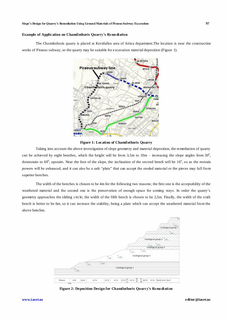
Example of Application on Chamilothoris Quarry’s Remediation
The Chamilothoris quarry is placed at Koridallos area of Attica department.The location is near the construction
works of Piraeus subway, so the quarry may be suitable for excavation material deposition (Figure 1).
Figure 1: Location of Chamilothoris Quarry
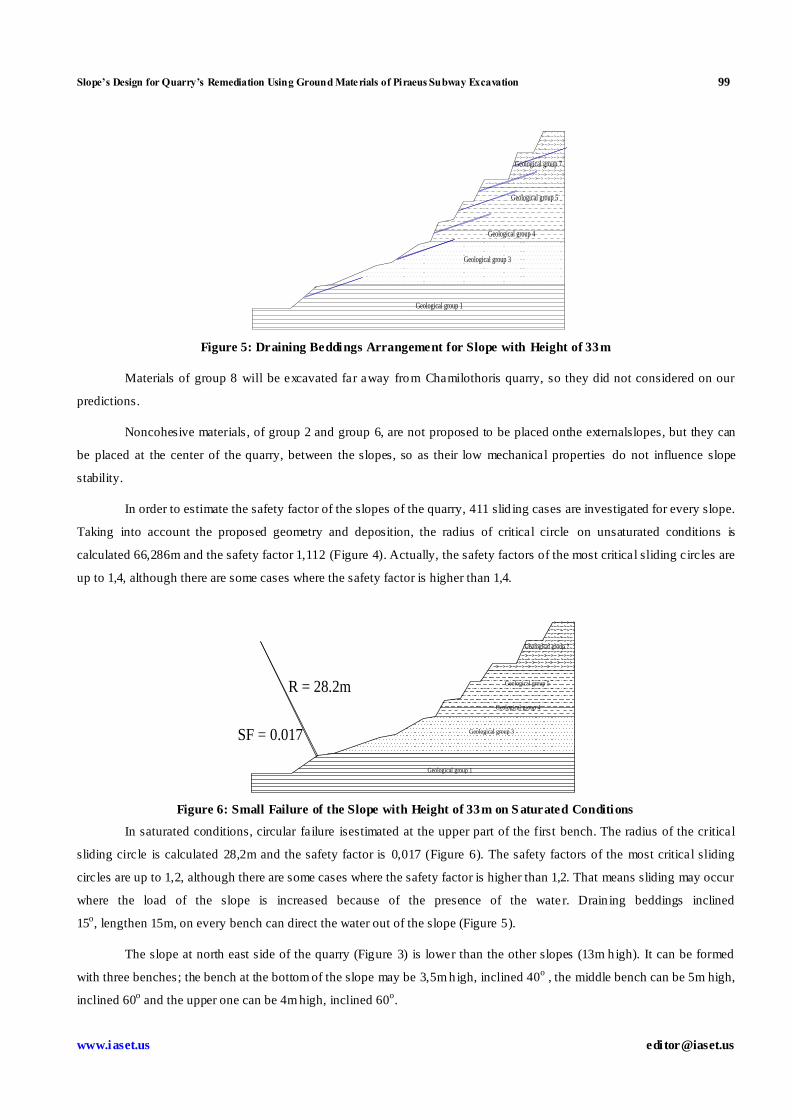
Taking into account the above investigation of slope geometry and material deposition, the remediat ion of quarry
can be achieved by eight benches, which the height will be from 3,5m to 10m – increasing the slope angles from 30o,
downstairs to 60o, upstairs. Near the foot of the slope, the inclination of the second bench will be 16
o, so as the restrain
powers will be enhanced, and it can also be a safe “plate” that can accept the eroded mate rial or the pieces may fall from
superior benches.
The width of the benches is chosen to be 4m for the following two reasons; the first one is the acceptability of the
weathered material and the second one is the preservation of enough space for coming ways. In order the quarry’s
geometry approaches the sliding circle; the width of the fifth bench is chosen to be 2,5m. Finally, the width of the sixth
bench is better to be 6m, so it can increase the stability, being a plate which can accept the weathered material from the
above benches.
Figure 2: Deposition Design for Chamilothoris Quarry’s Remediation
Geological group 1
6,59
+164+164,5
+168+168,5
+172+172,5
+176+176,5
+180
+184
+189
+193
+160
37,7
4
44,3
6
46,7
4
49,74 55,74 58,24 62,24 64,841,7435,7431,7425,7421,7410,24
0,00
Distance
Geological group 3
Geological group 4
Geological group 5
Geological group 7
98 M. Chatziangelou, B. Christaras, K. Botsou & EM. Malliaroudakis
Impact Factor (JCC): 2.6676 Index Copernicus Value (ICV): 3.0
Figure 3: Chamilithori’s Quarry
As the deposition of materials concerns, the materials with poor mechanical p roperties is proposed to be placed
downstairs, where the dips of benches are small, and cohesive materials are proposed to be placed upstairs, where the
benches are sheer.So, materials of group 1, like meta-madstone or clayey schist, with cohesion more than 3kPa, friction
angle more than 17o and apparent weight of 22kN/m
3, can be deposited at the bottom of the quarry. Under the materials of
group 1, materials of group 3, like meta-madstone or meta-sandstone, with cohesion more than 4kPa, frict ion angle more
than 20o and apparent weight of 20kN/m
3 are proposed to be placed. On the middle of the slope, material o f group 4, like
clayey stone, with cohesion more than 12kPa, frict ion angle more than 20o and apparent weight of 18kN/m
3, can be placed.
Just above this format ion, it can be deposited cohesive materials of g roup 5, like marl or mudstone, with cohesion more
than 35kPa, friction angle more than 25o and apparent weight of 19kN/m
3. Finally, on the upper benches, materials, of
lower mechanical p roperties than the previous group, can be placed , which cohesion may be at least 20kPa, the friction
angle may be at least 25o and the apparent weigh may be about 17kN/m
3. These properties are described by material of
group seven, like serpendinite (Figure 2).
Figure 4: Critical Sliding Circle of Slope with Height of 33m on Unsaturated Conditions
SF = 1.112
R = 66.286m
Geological group 1
Geological group 3
Geological group 4
Geological group 5
Geological group 7
Slope’s Design for Quarry’s Remediation Using Ground Materials of Piraeus Subway Excavation 99
www.iaset.us edi [email protected]
Figure 5: Draining Beddings Arrangement for Slope with Height of 33m
Materials of group 8 will be excavated far away from Chamilothoris quarry, so they did not considered on our
predictions.
Noncohesive materials, of group 2 and group 6, are not proposed to be placed onthe externalslopes, but they can
be placed at the center of the quarry, between the slopes, so as their low mechanical properties do not influence slope
stability.
In order to estimate the safety factor of the slopes of the quarry, 411 slid ing cases are investigated for every slope.
Taking into account the proposed geometry and deposition, the radius of critical circle on unsaturated conditions is
calculated 66,286m and the safety factor 1,112 (Figure 4). Actually, the safety factors of the most critical sliding circles are
up to 1,4, although there are some cases where the safety factor is higher than 1,4.
Figure 6: Small Failure of the Slope with Height of 33m on S aturated Conditions
In saturated conditions, circular failure isestimated at the upper part of the first bench. The radius of the critical
sliding circle is calculated 28,2m and the safety factor is 0,017 (Figure 6). The safety factors of the most critical sliding
circles are up to 1,2, although there are some cases where the safety factor is higher than 1,2. That means sliding may occur
where the load of the slope is increased because of the presence of the wate r. Drain ing beddings inclined
15o, lengthen 15m, on every bench can direct the water out of the slope (Figure 5).
The slope at north east side of the quarry (Figure 3) is lower than the other slopes (13m h igh). It can be formed
with three benches; the bench at the bottom of the slope may be 3,5m h igh, inclined 40o , the middle bench can be 5m high,
inclined 60o and the upper one can be 4m high, inclined 60
o.
Geological group 1
Geological group 3
Geological group 4
Geological group 5
Geological group 7
R = 28.2m
SF = 0.017
Geological group 1
Geological group 3
Geological group 4
Geological group 5
Geological group 7
100 M. Chatziangelou, B. Christaras, K. Botsou & EM. Malliaroudakis
Impact Factor (JCC): 2.6676 Index Copernicus Value (ICV): 3.0
Figure 7: Deposition Design for the North Eas t Side Slope of Chamilothoris Quarry’s Remediation
Figure 8: Critical Sliding Circle for the North East Side Slope with Height of 1
3m on Saturated and Unsaturated Conditions
The width of the bottom bench will be 6m and the width of the other two benches will be 4m.Materials of
group 5, like marl or madstone can be deposited on the bottom and materials of g roup 7, like serpendinite, can be deposited
under them (Figure 7). On unsaturated conditions, the radius of the critical sliding circle is calculated 18,824m and the
safety factor is calculated 1,738 (Figure 8).
The safety factors of the most critical sliding circles are up to 4, 5, although there are some cases where the safety
factor is higher than 4, 5. In saturated conditions, the radius of the critical circle is calculated 20,437 m and the safety
factor is calcu lated 1,517 (Figure 8). The safety factors of the most critical sliding circles are up to 4, although there are
some cases where the safety factor is higher than 4.
CONCLUSIONS
Taking into account that TBM is used for the subway’s excavation, the excavated rock mass is destroyed and
soiled. So, the deposits of geological formations of Pireaus subway excavation behave as soil. That means the failures of
the sliding of the slopes, which are formed by excavation materials, are circled. According to excavation format ions,
in order to investigate the suitable geometry of slopes stability, eight groups of geological formations, with different
mechanical characteristics, were d istinguished, according to excavation formations.
Slope stability was estimated using different slope geometry, taking into account the percent of geological
formations appearance and the excavated formations course.According to our investigation, the factors, which increase
+193
+189
+184
+180
0,00
3,26 9,26 11,76 15,76 18,26
Geological group 5
Geological group 7
Distance
Saturated conditionsR=20.437mSF = 1.517
Unsaturated conditionsR = 18.824m SF = 1.738
Geological group 5
Geological group 7
Slope’s Design for Quarry’s Remediation Using Ground Materials of Piraeus Subway Excavation 101
www.iaset.us edi [email protected]
slope stability, are; 1) Cohesive materials, 2) decrease of benches height from upstairs to downstairs, 3) geometry which
approaches the sliding circle, 4) benches inclined less than 60o, 5) formation of a midd le bench with two dips, 6) creation
of a wider level spot, so as enough space is created somewhere at the upper stages, in order to accept the pieces of upstairs .
Taking into account the above factors, that increase slope stability, the most suitable geometry of slope’s design for
quarry’s remediation using ground materials of Piraeus subway excavation, is succeeded by;
Benches from 3,5m to 5m height, lower downstairs and higher upstairs
Benches inclined from 30o to 60
o, where dips increase from downstairs to upstairs
Designing of enough space somewhere at the upper stages and downstairs, in order to accept the pieces which
may fall because of erosion of weathering.
Geometry approaches the sliding circle.
Deposition of materials with poor mechanical properties downstairs, where the slope is formed by small
inclinations.
Deposition of cohesive materials with best mechanical p roperties upstairs.
Use of cohesive material at the slopes and no cohesive materials at the middle of the quarry
The above investigation is applied on Chamilothoris quarry’s remediation. In unsaturated conditions, he radius of
slopes critical circle is calcu lated 66,286m and the safety factor 1,112. Actually, the safety factors of the most critical
sliding circles arebetween 1,1 and 1,4, although there are some cases , where the safety factor is higher than 1,4.
In saturated conditions, circular failure is estimated at the upper part of the first bench. The radius of the critical
sliding circle is calcu lated 28,2m and the safety factor is 0,017. The safety factors of the most crit ical sliding circles are up
to 1,2, although there are some cases where the safety factor is higher than 1,2. That means sliding may occur where the
load of the slope is increased because of the presence of the water. The sliding may be deterred by draining beddings
inclined 15o, lengthen 15 m, on every bench, which they can direct the water out of the slope.
REFERENCES
1. Abramson, K.W., Lee, T.S., Sharma, S., Boyce, G.M. (2002) Slope Stability and Stabilization methods.
John Wiley & Sons Inc. pp. 712.Nash, 1987
2. Berilgen, M. (2006). Investigation of stability of slopes under drawdown conditions, Computers and Geotechnics,
Elsevier 2006, www.Elsevier.com
3. Bishop, A.W. (1955) "The Use of the Slip Circle in the Stability Analysis of Slopes", Geotechnique,
Great Britain, vol. 5, No. 1, Mar., pp. 7-17
4. Bishop, A.W. and Morgenstern, N. (1960) Stability Coefficients for Earth Slopes. Geotechnique. Institution of
Civil Engineers, London, vol. 10, No. 4, December, pp. 129-150.
5. Craig, R.F. (2005). Craig’s soil mechanics. Spon Press, Taylor and Francis Group, London and New York
6. Das, B.M. (2005). Fundamental of geotechnical engineering, Nelson, USA, 2005
102 M. Chatziangelou, B. Christaras, K. Botsou & EM. Malliaroudakis
Impact Factor (JCC): 2.6676 Index Copernicus Value (ICV): 3.0
7. Deschamps, R., Hynes Chr., Bourdeau Ph. (1999). Embankment widening design guidelines and construction
procedures. Purdue University, West Lafayette, Indiana, 64p.
8. Duncan, J. M., Wright, S. G. (1980). The Accuracy of Equilibrium Methods of Slope Stability Analysis.
Engineering Geology, 16(1/2), pp 5-17.
9. Duncan, H.M.and Wright, S.G. (2005).Factor of Safety and Reliab ility. So il Strength and Slope Stability, John
Wiley and Sons, 2005, pp.19-211
10. Kumar, J. and Samui, P. (2006).Stability Determination for Layered Soil Slopes using the Upper Bound Limit
Analysis. Geotechnical and Geological Engineering Journal, Springer Publicat ions, vol. 24, 1803-1819.
11. Siddique, A., Safiullah, A.M.M. and Ansary M.A. (2005). An investigation into embankment failure along a
section of a major highway, Proceeding of the 16th
International Conference on Soil Mechanics and Geotechical
Engineering, Vol.1-5, 2005, pp.979-983.