51
Control Systems and Protections

Control Systemsand
Protections

What Makes Up a Controls System?• Engine/prime mover control systems
– Speed control/governor
– Load (kW) control (paralleled systems)
– Protection systems (low oil pressure, high temperatures…)
• Generator control systems– Output voltage control
– Load (VAR) control
– Protection systems (excessive current, over voltage…)
• Distribution control/protection systems (300% S.C.)???

Engine-Generator Control Systems
Sample engine control systems
Sample generator control systems
Control System Functions• Control the production and distribution of power
• Improve safety of the generating system
• Protect the generator
• Protect loads connected to the generator system

Generator Control Systems• Voltage regulation/VAR control
– Stand-alone operation (island mode)
– Paralleled applications (similar sized units)
– Co-gen applications (connected to grid)
• Monitoring and control
• Basic generator protection– Recommended minimum protection
– Recommended additional protection

Generator Control Systems (cont.)
Gen
Excitation
Protection
Monitoring & control
To load
Field
BasicOV/UVOF/UFOC/OL
AdvancedDifferential
Ground faultStator temp
Bearing tempReactive powerReverse powerNeg. sequence
Voltage RegulatorVAR/PF controlCurrent limiting
Diode protection
Digital/analogRevenue gradeCommunication
networks

Typical Interconnection Drawing
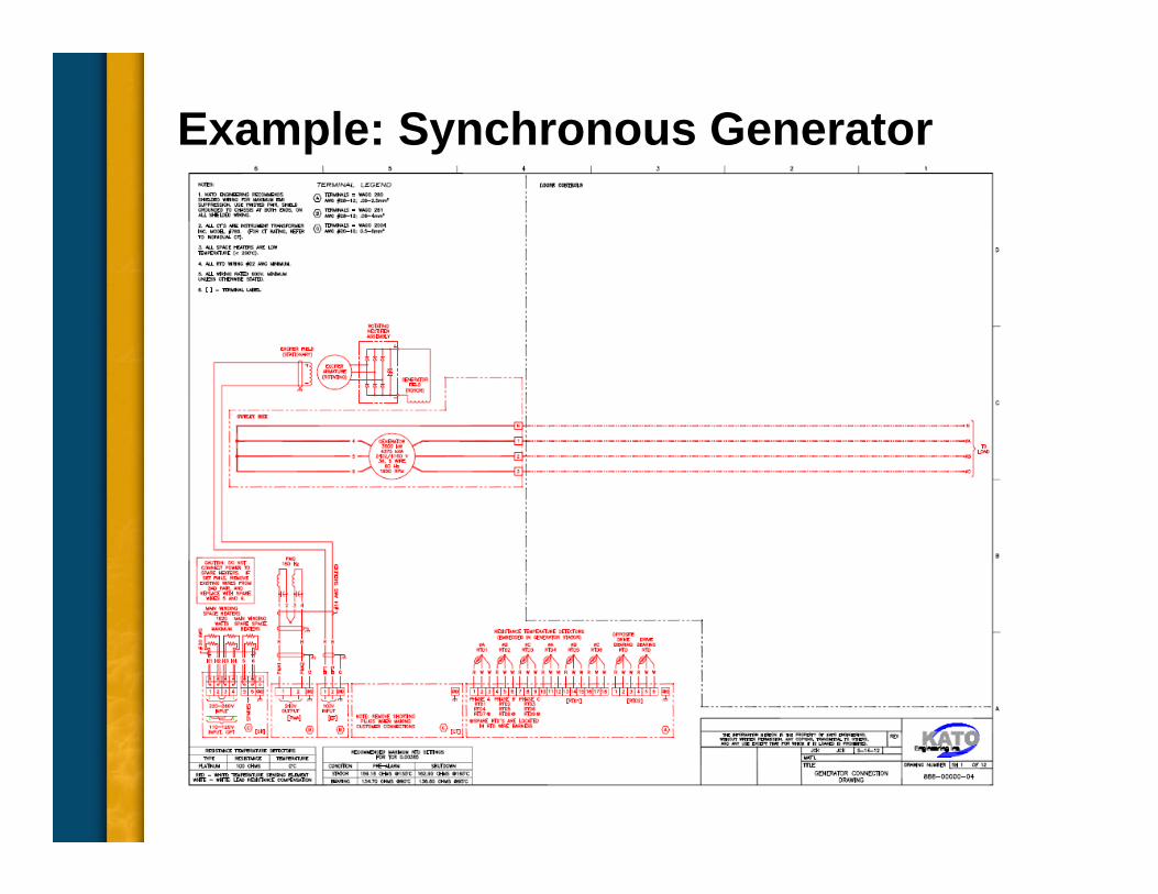
Example: Synchronous Generator

Generator Excitation Control• Basic excitation systems
– Voltage regulators (field excitation/voltage regulation)
– Redundant regulator systems
– Analog vs. digital
• Parallel operation– More to consider

Voltage Regulators
• Simple manual field excitation devices
Automatic voltage regulators
Analog AVR
Digital AVR
Simple PS

Redundant Voltage Regulators

Analog and Digital Comparison• Analog voltage regulators
– Typically lower cost
– Mature designs
– Many OEM and customers are familiar with technology
– Average sensing regulation (typically not RMS)
– Limited versatility
– Becoming more difficult to obtain and maintain……

Analog and Digital Comparison (cont.)• Digital voltage regulators
– Typically higher cost for basic functionality
– Digital designs now becoming more widely used
– RMS sensing regulation standard
– Highly versatile
– Many additional features enabled by digital technology (data monitoring, protective relaying, generator protection built in…)

Voltage Regulator and Load CB

Parallel Operation Control• Stand alone operation (island mode)
– No paralleling controls required
• Paralleled Applications (similar-sized units)
• Micro-Grid
• Can be run in droop or cross current compensation mode
• Co-gen applications (connected to grid)– Large utility grid
– Must run in droop mode or in VAR / PF mode

Stand Alone Operation (Island Mode)
Paralleling controls are not required

Paralleled Applications (Micro Grid)• For operating in
parallel with similar sized units (non utility or larger gen)
• “Cross current” paralleling controls typical

Voltage Regulator with CCCT
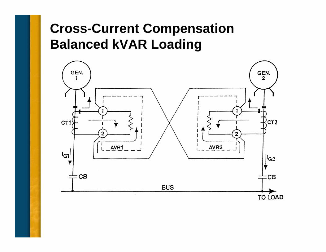
Cross-Current Compensation Balanced kVAR Loading

Co-Gen Applications• For operating in
parallel with utility or large generator set or turbine generator
• “Droop mode” paralleling controls needed
• VAR and Current limiting needed

Reactive Load (VAR/PF) Control• For operating in parallel with utility
• Don’t use pure VAR control on single, isolated generator.– Voltage control issues arise.
– Must be disabled when generator is not paralleled.
– Use voltage control mode (Standard mode)

VAR/PF Control

Current Limiting (300%)

Monitoring and Control• Quality sensing devices
– Current transformers (CTs)
– Potential transformers (PTs)
• Data logging
• Remote control
• Revenue billing

Sensing CTs and PTs• Sensing current transformers (CTs)
– Size from miniature PCB to “bar type”
• Sensing potential transformers (PTs)– Miniature to medium voltage

Current Transformers
Bar type
Donut type
Donut type withlead support

Current Transformer Installation
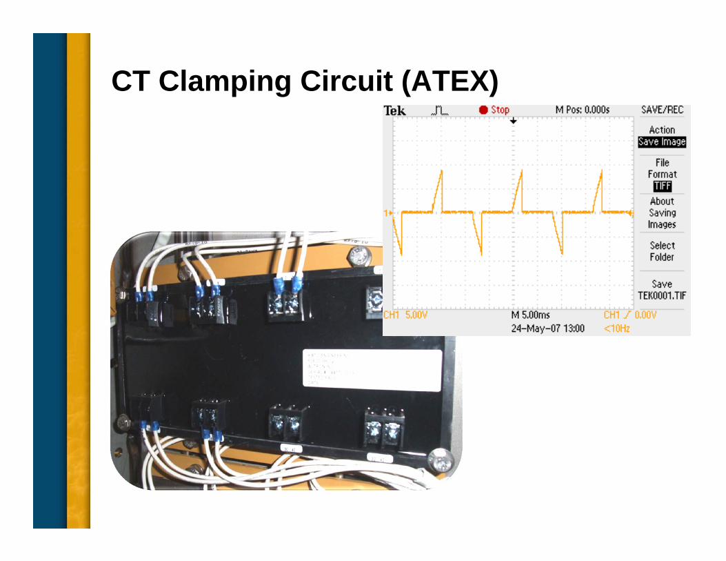
CT Clamping Circuit (ATEX)

Potential Transformer Installation

Monitoring and Control

Advanced Monitoring and Control
Network enabled systems becoming the norm

Generator Protection• Recommended minimum protection
– Under-frequency (as a control: not true protection)
– Over-voltage
– Phase over-current

ANSI Device NumbersList of ANSI/IEEE Device Numbers and Acronyms
1 – Master Element 33 – Position Switch 65 – Governor2 – Time Delay Starting or Closing Relay 34 – Master Sequence Device 66 – Notching or Jogging Device3 – Checking or Interlocking Relay 35 – Brush‐Operating or Slip‐Ring Short‐Circuiting Device 67 – AC Directional Overcurrent Relay4 – Master Contactor 36 – Polarity or Polarizing Voltage Devices 68 – Blocking or "Out‐of‐Step" Relay5 – Stopping Device 37 – Undercurrent or Under Power Relay 69 – Permissive Control Device6 – Starting Circuit Breaker 38 – Bearing Protective Device 70 – Rheostat7 – Rate of Change Relay 39 – Mechanical Condition Monitor 71 – Liquid Level Switch8 – Control Power Disconnecting Device 40 – Field (over/under excitation) Relay 72 – DC Circuit Breaker9 – Reversing Device 41 – Field Circuit Breaker 73 – Load‐Resistor Contactor10 – Unit Sequence Switch 42 – Running Circuit Breaker 74 – Alarm Relay11 – Multi‐function Device 43 – Manual Transfer or Selector Device 75 – Position Changing Mechanism12 – Overspeed Device 44 – Unit Sequence Starting Relay 76 – DC Overcurrent Relay13 – Synchronous‐speed Device 45 – Abnormal Atmospheric Condition Monitor 77 – Telemetering Device14 – Underspeed Device 46 – Reverse‐phase or Phase‐Balance Current Relay 78 – Phase‐Angle Measuring Relay15 – Speed – or Frequency, Matching Device 47 – Phase‐Sequence or Phase‐Balance Voltage Relay 79 – AC Reclosing Relay16 – Data Communications Device 48 – Incomplete Sequence Relay 80 – Flow Switch17 – Shunting or Discharge Switch 49 – Machine or Transformer, Thermal Relay 81 – Frequency Relay18 – Accelerating or Decelerating Device 50 – Instantaneous Over Current Relay 82 – DC Reclosing Relay19 – Starting to Running Transition Contactor 51 – AC Inverse Time Over Current Relay 83 – Automatic Selective Control or Transfer Relay20 – Electrically Operated Valve 52 – AC Circuit Breaker 84 – Operating Mechanism21 – Distance Relay 53 – Exciter or DC Generator Relay 85 – Communications, Carrier or Pilot‐Wire Relay22 – Equalizer Circuit Breaker 54 – Turning Gear Engaging Device 86 – Lockout Relay23 – Temperature Control Device 55 – Power Factor Relay 87 – Differential Protective Relay24 – Volts Per Hertz Relay 56 – Field Application Relay 88 – Auxiliary Motor or Motor Generator25 – Synchronizing or Synchronism‐Check Device 57 – Short‐Circuiting or Grounding Device 89 – Line Switch26 – Apparatus Thermal Device 58 – Rectification Failure Relay 90 – Regulating Device27 – Undervoltage Relay 59 – Overvoltage Relay 91 – Voltage Directional Relay28 – Flame detector 60 – Voltage or Current Balance Relay 92 – Voltage and Power Directional Relay29 – Isolating Contactor or Switch 61 – Density Switch or Sensor 93 – Field Changing Contactor30 – Annunciator Relay 62 – Time‐Delay Stopping or Opening Relay 94 – Tripping or Trip‐Free Relay 31 – Separate Excitation Device 63 – Pressure Switch32 – Directional Power Relay 64 – Ground Detector Relay

Under Frequency• Control-type
operates through voltage regulator– Controls generator
voltage proportional to frequency
• Protection-type may be needed to protect other equipment– Required to trip
generator offline upon under frequency detection

Over-Voltage Protection• Should be used with every generator
• Protects loads as well as generator and exciter
• Must remove excitation from generator

Over Voltage Protection (cont.)
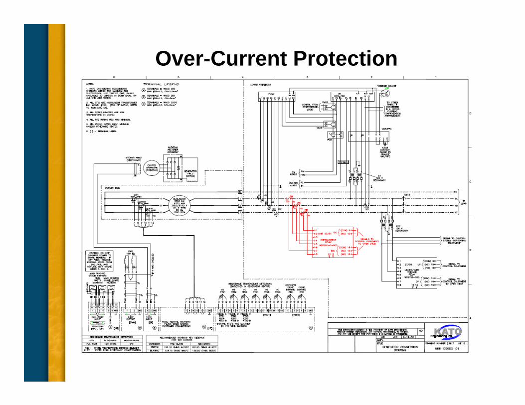
Over-Current Protection

Additional Generator Protection• Required for some but not every installation (specification
driven.– Exciter diode fault protection
– Negative sequence over current
– Differential over current
– Lightning arrestors and surge capacitors

Exciter Diode Failure Protection• Indirect-type monitors ripple current in exciter field
winding
• Protects against generator field overheating

Diode Fault Protection

Negative Sequence Protection• Also known as unbalanced current protection.
• Needed when there is any chance of unbalanced load.
• For Kato™ generators, k factor is 40(k factor = (I2)2 t)

Negative SequenceMaximum Current vs. Minimum Current
00.10.20.30.40.50.60.70.80.9
0 0.2 0.4 0.6 0.8 1Maximum current/rated current
Min
imum
cur
rent
/rat
ed
curr
ent
Allowable unbalance Excessive
unbalance
Based on a 10% equivalent negative sequence current

Negative Sequence Protection

Differential Current Protection• Compares currents of corresponding phase & neutral
windings.
• Does not prevent damage, but limits damage.
• CTs must be identical at both ends of windings.
• Watch for applications energizing large transformers.

Differential Current Protection

Lightning Arrestors, Surge Capacitors• Protect generator windings against lightning and
switching. (What happens if not protected? Why?)
• Should be used on all medium and high-voltage generators.
• As close to generator as possible.
• Use high-quality, low impedance, arrestors.

Lightning Protection

Capacitor/Arrestor Location
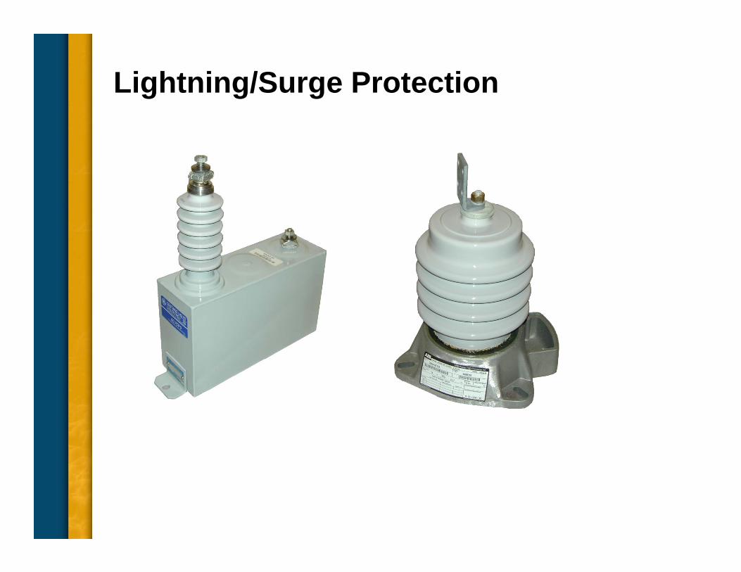
Lightning/Surge Protection

Lightning/Surge Protection (cont.)
Typical installation

General Recommended Protection


