337
Driver’s Handbook

PACCAR Australia and Kenworth Plant Bayswater Victoria
Every PACCARtruck is supported in the
field by a comprehensive networkof highly qualified dealers situated throughout
Australia, New Zealand and Papua New Guinea.Each with a history of excellence in the trucking industry.
Drive
r’s Ha
nd
bo
ok
20-64 Canterbury Road, Bayswater 3153P.O. Box 60, Bayswater, Victoria, Australia 3153Telephone: (03) 9721 1500Facsimile: (03) 9720 4144Internet: www.kenworth.com.au
Driver’s HandbookDriver’s HandbookD
river’s H
an
db
oo
k

VEHICLE IDENTIFICATION
Owner’s Name: ........................Address: ...............................................
Suburb: ....................................State: .................Postcode: ................
Phone Number (Business): .....................................................................
Phone Number (Private): .........................................................................
Vehicle Registration Number: ..................................................................
Colour: .....................................................................................................
Model: ......................................................................................................
Engine Number: .......................................................................................
VlN (Vehicle Identification Number): ........................................................
Chassis Number: .....................................................................................
MAXIMUM VEHICLE WEIGHTThe maximum vehicle weight ratings are stamped on the Vehicle Identification Plate attached to the body. Refer to page 223 for locations.Registered Tare Weight: ..........................................................................
GVM (Gross Vehicle Mass): ....................................................................
GCM (Gross Combination Mass): ...........................................................
Date of Acquisition: ..................................................................................
Date: .....................................
Stamp & Signature
of Selling Dealer:
The above information fully identifies your vehicle. It will furnish all of the necessary information in the event that warranty repairs are required. Be certain it is completely and properly filled out and signed by your selling dealer or his/her authorised representative. NOTE: Original ratings letter is supplied by the selling dealer for every truck.

WELCOME TO THE KENWORTH FAMILY
We thank you for investing in your new Kenworth. Proudly engineered and built in Australia, this vehicle has been custom designed to meet your exacting standards and the specific requirements of your application. Advanced technology, pride in workmanship and a total commitment to quality have been combined to produce a truck that is unequalled.
Our network of dealers will support your Kenworth with the same quality and attention to detail that went into its manufacture. Anywhere in Australia, New Zealand and Papua New Guinea, support for your investment is only as far away as a phone call to your nearest Kenworth dealer.
Australian Kenworth or DAF owners in need of emergency roadside assistance can simply call 1800 4 PACCAR (1800 4 72222). Trained operators are available 24-7 to connect you with your nearest PACCAR dealer for support.
Please take the time to read this handbook, as it contains information that will assist you in getting the most from your new Kenworth. We know it will provide many years of productive service, and we welcome you to the family of Kenworth owners.
Australia Pty. Ltd.Australia

CAT: 8030 November 2017 Page iii
CONTENTS
INTRODUCTIONList of tables . . . . . . . . . . . . . . . . . . . . . . . . . . . . . . . . . . . . . . . . . . . . . . . . xiAbout this Handbook . . . . . . . . . . . . . . . . . . . . . . . . . . . . . . . . . . . . . . . . . xiiSafety symbols . . . . . . . . . . . . . . . . . . . . . . . . . . . . . . . . . . . . . . . . . . . . . xivVehicle safety . . . . . . . . . . . . . . . . . . . . . . . . . . . . . . . . . . . . . . . . . . . . . . .xvDriver Information Pack (DIP) . . . . . . . . . . . . . . . . . . . . . . . . . . . . . . . . . xvi
SECTION ONE - OPERATING INSTRUCTIONS
GENERAL INFORMATION. . . . . . . . . . . . . . . . . . . . . . . . . . . . . . . . . . . . . .1Vehicle access . . . . . . . . . . . . . . . . . . . . . . . . . . . . . . . . . . . . . . . . . . . . . . .1Keys and locks . . . . . . . . . . . . . . . . . . . . . . . . . . . . . . . . . . . . . . . . . . . . . . .1Ignition key switch . . . . . . . . . . . . . . . . . . . . . . . . . . . . . . . . . . . . . . . . . . .2Remote keyless entry (RKE) . . . . . . . . . . . . . . . . . . . . . . . . . . . . . . . . . . . .3Remote verification . . . . . . . . . . . . . . . . . . . . . . . . . . . . . . . . . . . . . . . . . . .3Keypad transmitter . . . . . . . . . . . . . . . . . . . . . . . . . . . . . . . . . . . . . . . . . . . .4Programming . . . . . . . . . . . . . . . . . . . . . . . . . . . . . . . . . . . . . . . . . . . . . . . .4Cab and frame access . . . . . . . . . . . . . . . . . . . . . . . . . . . . . . . . . . . . . . . . .5Active Cab Entry (ACE) . . . . . . . . . . . . . . . . . . . . . . . . . . . . . . . . . . . . . . . .8
ENGINE ACCESS . . . . . . . . . . . . . . . . . . . . . . . . . . . . . . . . . . . . . . . . . . . . .12 Conventional hood hold-downs . . . . . . . . . . . . . . . . . . . . . . . . . . . . . . . . . . .12
K200 cab tilt system. . . . . . . . . . . . . . . . . . . . . . . . . . . . . . . . . . . . . . . . . .14HOW TO RAISE AND LOWER THE CAB . . . . . . . . . . . . . . . . . . . . . . . .16 To raise the cab . . . . . . . . . . . . . . . . . . . . . . . . . . . . . . . . . . . . . . . . . . . . .16 To lower the cab . . . . . . . . . . . . . . . . . . . . . . . . . . . . . . . . . . . . . . . . . . . . .16 General maintenance . . . . . . . . . . . . . . . . . . . . . . . . . . . . . . . . . . . . . . . .18 Removing excess air from the system . . . . . . . . . . . . . . . . . . . . . . . . . .18 System contamination . . . . . . . . . . . . . . . . . . . . . . . . . . . . . . . . . . . . . . . .19SAFE VEHICLE OPERATION . . . . . . . . . . . . . . . . . . . . . . . . . . . . . . . . . .20VEHICLE LOADING. . . . . . . . . . . . . . . . . . . . . . . . . . . . . . . . . . . . . . . . . . . .20EMERGENCY EQUIPMENT . . . . . . . . . . . . . . . . . . . . . . . . . . . . . . . . . . . . .21DRIVER’S CHECKLIST. . . . . . . . . . . . . . . . . . . . . . . . . . . . . . . . . . . . . . . . .21
Approaching your vehicle . . . . . . . . . . . . . . . . . . . . . . . . . . . . . . . . . . . . .22DAILY CHECKS . . . . . . . . . . . . . . . . . . . . . . . . . . . . . . . . . . . . . . . . . . . . . .23
Engine compartment . . . . . . . . . . . . . . . . . . . . . . . . . . . . . . . . . . . . . . . . .23Chassis and cab . . . . . . . . . . . . . . . . . . . . . . . . . . . . . . . . . . . . . . . . . . . . .23
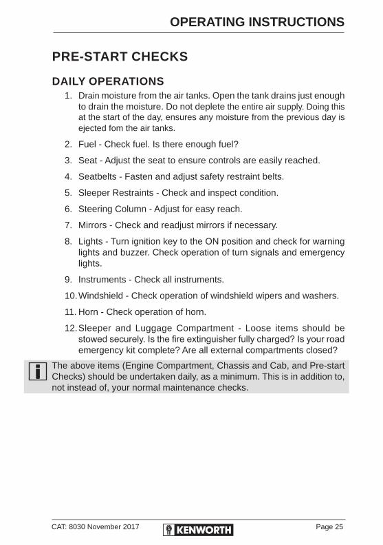
PRE-START CHECKS . . . . . . . . . . . . . . . . . . . . . . . . . . . . . . . . . . . 25 Daily operations . . . . . . . . . . . . . . . . . . . . . . . . . . . . . . . . . . . . . . . 25 Weekly operations . . . . . . . . . . . . . . . . . . . . . . . . . . . . . . . . . . . . . . . . . . .26INSTRUMENTS AND CONTROLS . . . . . . . . . . . . . . . . . . . . . . . . . . . . .28
Instrument Panel . . . . . . . . . . . . . . . . . . . . . . . . . . . . . . . . . . . . . . . . . . . .28Adjustable steering column . . . . . . . . . . . . . . . . . . . . . . . . . . . . . . . . . . .28Dash layout - K200 models . . . . . . . . . . . . . . . . . . . . . . . . . . . . . . . . . . . .29Conventional dash layout - T3, T4, T6, T9 & C5 models . . . . . . . . . . . .30

Page iv CAT: 8030 November 2017
CONTENTS
Warning lights. . . . . . . . . . . . . . . . . . . . . . . . . . . . . . . . . . . . . . . . . . . . . . .31Power on test . . . . . . . . . . . . . . . . . . . . . . . . . . . . . . . . . . . . . . . . . . . . . . .32Speedometer/Odometer. . . . . . . . . . . . . . . . . . . . . . . . . . . . . . . . . . . . . . .33Tachourmeter . . . . . . . . . . . . . . . . . . . . . . . . . . . . . . . . . . . . . . . . . . . . . . .34Engine oil pressure gauge. . . . . . . . . . . . . . . . . . . . . . . . . . . . . . . . . . . . .35Engine coolant temperature gauge . . . . . . . . . . . . . . . . . . . . . . . . . . . . .36Air system pressure gauges . . . . . . . . . . . . . . . . . . . . . . . . . . . . . . . . . . .36
AIR LOSS EMERGENCY PROCEDURE . . . . . . . . . . . . . . . . . . . . . . . . . .37 Low air audible alarm . . . . . . . . . . . . . . . . . . . . . . . . . . . . . . . . . . . . . . .38
Parking brake valve . . . . . . . . . . . . . . . . . . . . . . . . . . . . . . . . . . . . . . . . . .39Fuel level gauge . . . . . . . . . . . . . . . . . . . . . . . . . . . . . . . . . . . . . . . . . . . . .40Voltmeter . . . . . . . . . . . . . . . . . . . . . . . . . . . . . . . . . . . . . . . . . . . . . . . . . . .40Transmission low oil warning light. . . . . . . . . . . . . . . . . . . . . . . . . . . . . .41Two-speed rear axle (range) switch . . . . . . . . . . . . . . . . . . . . . . . . . . . . .41Headlight switch. . . . . . . . . . . . . . . . . . . . . . . . . . . . . . . . . . . . . . . . . . . . .42Emergency left hand headlight . . . . . . . . . . . . . . . . . . . . . . . . . . . . . . . . .42High beam . . . . . . . . . . . . . . . . . . . . . . . . . . . . . . . . . . . . . . . . . . . . . . . . . .42Emergency flasher switch . . . . . . . . . . . . . . . . . . . . . . . . . . . . . . . . . . . . .42Panel light knob (dimmer switch) . . . . . . . . . . . . . . . . . . . . . . . . . . . . . . .43ID and clearance lights switch . . . . . . . . . . . . . . . . . . . . . . . . . . . . . . . . .43Fog lights switch . . . . . . . . . . . . . . . . . . . . . . . . . . . . . . . . . . . . . . . . . . . .43Dome (interior) light switch (K200 only) . . . . . . . . . . . . . . . . . . . . . . . . .43Mirrors . . . . . . . . . . . . . . . . . . . . . . . . . . . . . . . . . . . . . . . . . . . . . . . . . . . . .44Power Windows . . . . . . . . . . . . . . . . . . . . . . . . . . . . . . . . . . . . . . . . . . . .44Air suspension deflate switch (dump valve) . . . . . . . . . . . . . . . . . . . . . .44iPod & MP3 connectivity . . . . . . . . . . . . . . . . . . . . . . . . . . . . . . . . . . . . .45Windshield wipers/washers control . . . . . . . . . . . . . . . . . . . . . . . . . . . . .45Engine fan switch (manual override) . . . . . . . . . . . . . . . . . . . . . . . . . . . .46Cab mounted power supply socket . . . . . . . . . . . . . . . . . . . . . . . . . . . . .46Cruise control . . . . . . . . . . . . . . . . . . . . . . . . . . . . . . . . . . . . . . . . . . . . . . .47Smartwheel mounted controls . . . . . . . . . . . . . . . . . . . . . . . . . . . . . . . . .48Cummins ‘C’ brake . . . . . . . . . . . . . . . . . . . . . . . . . . . . . . . . . . . . . . . . . . .49Smartwheel mounted engine brake controls . . . . . . . . . . . . . . . . . . . . .49Turbo timer . . . . . . . . . . . . . . . . . . . . . . . . . . . . . . . . . . . . . . . . . . . . . . . . .50Shift pattern display. . . . . . . . . . . . . . . . . . . . . . . . . . . . . . . . . . . . . . . . . .51Engine control unit (ECU) self test lights . . . . . . . . . . . . . . . . . . . . . . . .51Cummins engine management/diagnostic/fault codes . . . . . . . . . . . . .51How to display the flash codes. . . . . . . . . . . . . . . . . . . . . . . . . . . . . . . . .51
HEATING AND AIRCONDITIONING . . . . . . . . . . . . . . . . . . . . . . . . . . . . .53 Cab heater/airconditioner . . . . . . . . . . . . . . . . . . . . . . . . . . . . . . . . . . . . .54CAB STORAGE. . . . . . . . . . . . . . . . . . . . . . . . . . . . . . . . . . . . . . . . . . . . . . .58 Interior compartments . . . . . . . . . . . . . . . . . . . . . . . . . . . . . . . . . . . . . . . .58 Toolboxes . . . . . . . . . . . . . . . . . . . . . . . . . . . . . . . . . . . . . . . . . . . . . . . . .58

CAT: 8030 November 2017 Page v
CONTENTS
SEATS . . . . . . . . . . . . . . . . . . . . . . . . . . . . . . . . . . . . . . . . . . . . . . . . . . . . . . .59Seat adjustment . . . . . . . . . . . . . . . . . . . . . . . . . . . . . . . . . . . . . . . . . . . . .59
SAFETY RESTRAINT BELTS . . . . . . . . . . . . . . . . . . . . . . . . . . . . . . . . . .60Lap and shoulder belt . . . . . . . . . . . . . . . . . . . . . . . . . . . . . . . . . . . . . . . .61
Sleeper, bunks and restraints . . . . . . . . . . . . . . . . . . . . . . . . . . . . . . . . . .62OPERATING THE ENGINE . . . . . . . . . . . . . . . . . . . . . . . . . . . . . . . . . . . .63
Normal starting procedure . . . . . . . . . . . . . . . . . . . . . . . . . . . . . . . . . . . .63Engine warm-up . . . . . . . . . . . . . . . . . . . . . . . . . . . . . . . . . . . . . . . . . . . . .64Idling the engine . . . . . . . . . . . . . . . . . . . . . . . . . . . . . . . . . . . . . . . . . . . .67
ENGINE AFTERTREATMENT SYSTEMS (EAS) . . . . . . . . . . . . . . . . . . .68Selective Catalytic Reduction (SCR) . . . . . . . . . . . . . . . . . . . . . . . . . . . .68AdBlue low level warning and inducement . . . . . . . . . . . . . . . . . . . . . .68EAS Tampering . . . . . . . . . . . . . . . . . . . . . . . . . . . . . . . . . . . . . . . . . . . . .69Diesel Exhaust Fluid (DEF) - AdBlue Quantity . . . . . . . . . . . . . . . . . . . .69“Engine Derate” Means: Engine Power Limiting . . . . . . . . . . . . . . . . . .69Diesel Exhaust Fluid (DEF) - AdBlue . . . . . . . . . . . . . . . . . . . . . . . . . . . .70AdBlue filling . . . . . . . . . . . . . . . . . . . . . . . . . . . . . . . . . . . . . . . . . . . . . . .71Diesel Particulate Filter (DPF) . . . . . . . . . . . . . . . . . . . . . . . . . . . . . . . . .71EAS warning lights . . . . . . . . . . . . . . . . . . . . . . . . . . . . . . . . . . . . . . . . . .71DPF rengeneration . . . . . . . . . . . . . . . . . . . . . . . . . . . . . . . . . . . . . . . . . .72Functionality . . . . . . . . . . . . . . . . . . . . . . . . . . . . . . . . . . . . . . . . . . . . . . .72Controlling the regeneration process . . . . . . . . . . . . . . . . . . . . . . . . . . .72Three position regeneration switch . . . . . . . . . . . . . . . . . . . . . . . . . . . . .73
OPERATING THE TRANSMISSION . . . . . . . . . . . . . . . . . . . . . . . . . . . .74 Transmission oil pressure . . . . . . . . . . . . . . . . . . . . . . . . . . . . . . . . . . . .74PUTTING THE VEHICLE IN MOTION. . . . . . . . . . . . . . . . . . . . . . . . . . .75
Shifting gears in a new vehicle . . . . . . . . . . . . . . . . . . . . . . . . . . . . . . . .76Clutch brake and travel . . . . . . . . . . . . . . . . . . . . . . . . . . . . . . . . . . . . . . .76Double clutching . . . . . . . . . . . . . . . . . . . . . . . . . . . . . . . . . . . . . . . . . . . .77
CLUTCH OPERATION . . . . . . . . . . . . . . . . . . . . . . . . . . . . . . . . . . . . . . . .78Starting . . . . . . . . . . . . . . . . . . . . . . . . . . . . . . . . . . . . . . . . . . . . . . . . . . . .78Transmission oil temperature gauge . . . . . . . . . . . . . . . . . . . . . . . . . . . .79Transmission shift patterns . . . . . . . . . . . . . . . . . . . . . . . . . . . . . . . . . . . .80
AUTOMATIC TRANSMISSIONS . . . . . . . . . . . . . . . . . . . . . . . . . . . . . . . . .82Operating automatic transmissions . . . . . . . . . . . . . . . . . . . . . . . . . . . . .82Checking automatic fluid levels . . . . . . . . . . . . . . . . . . . . . . . . . . . . . . . .83
EATON FULLER TRANSMISSIONS . . . . . . . . . . . . . . . . . . . . . . . . . . . .85UltraShift transmissions . . . . . . . . . . . . . . . . . . . . . . . . . . . . . . . . . . . . . .85Driver diagnosis – UltraShift . . . . . . . . . . . . . . . . . . . . . . . . . . . . . . . . . . .88Retrieving fault codes . . . . . . . . . . . . . . . . . . . . . . . . . . . . . . . . . . . . . . .88Driving the UltraShift transmissions . . . . . . . . . . . . . . . . . . . . . . . . . . . .89UltraShift driving tips . . . . . . . . . . . . . . . . . . . . . . . . . . . . . . . . . . . . . . . . .91Clearing fault codes . . . . . . . . . . . . . . . . . . . . . . . . . . . . . . . . . . . . . . . . . .93UltraShift Plus transmissions . . . . . . . . . . . . . . . . . . . . . . . . . . . . . . . . . .95Start-up & power down . . . . . . . . . . . . . . . . . . . . . . . . . . . . . . . . . . . . . . .96
Page vi CAT: 8030 November 2017
CONTENTS
USING THE BRAKE SYSTEM . . . . . . . . . . . . . . . . . . . . . . . . . . . . . . . . .99Air supply system . . . . . . . . . . . . . . . . . . . . . . . . . . . . . . . . . . . . . . . . . . .99Brake operation . . . . . . . . . . . . . . . . . . . . . . . . . . . . . . . . . . . . . . . . . . . .100
USING THE PARKING BRAKE . . . . . . . . . . . . . . . . . . . . . . . . . . . . . . .100Before you leave the cab . . . . . . . . . . . . . . . . . . . . . . . . . . . . . . . . . . . .101 To release the truck parking brakes ONLY . . . . . . . . . . . . . . . . . . .101 To release the full combination of brakes . . . . . . . . . . . . . . . . . . . .101
TRUCK/TRAILER AIR SUPPLY VALVE . . . . . . . . . . . . . . . . . . . . . . .102TRAILER PARK BRAKE RELEASE VALVE . . . . . . . . . . . . . . . . . . .103SYSTEM TRUCK PARK . . . . . . . . . . . . . . . . . . . . . . . . . . . . . . . . . . . . . .104BRAKE SAFETY AND EMERGENCY . . . . . . . . . . . . . . . . . . . . . . . . . .104EMERGENCY BRAKING . . . . . . . . . . . . . . . . . . . . . . . . . . . . . . . . . . . . .104FOR NON ABS VEHICLES . . . . . . . . . . . . . . . . . . . . . . . . . . . . . . . . . . .105DISC BRAKES . . . . . . . . . . . . . . . . . . . . . . . . . . . . . . . . . . . . . . . . . . . . . . .105EBSS - ELECTRONIC BRAKING SAFETY SYSTEMS . . . . . . . . . . . .106
Anti-Lock Braking System (ABS) . . . . . . . . . . . . . . . . . . . . . . . . . . . . .106ABS warning lamp . . . . . . . . . . . . . . . . . . . . . . . . . . . . . . . . . . . . . . . . .106Automatic Traction Control (ATC) . . . . . . . . . . . . . . . . . . . . . . . . . . . . .107Drag Torque Control (DTC) . . . . . . . . . . . . . . . . . . . . . . . . . . . . . . . . . . .108Electronic Stability Program (ESP) . . . . . . . . . . . . . . . . . . . . . . . . . . . .108Trailer Response Management (TRM) . . . . . . . . . . . . . . . . . . . . . . . . . .108 Active Cruise with Brakes (ACB) . . . . . . . . . . . . . . . . . . . . . . . . . . . . . .108
OFF-ROAD FUNCTION. . . . . . . . . . . . . . . . . . . . . . . . . . . . . . . . . . . . . . .109ABS off-road function switch . . . . . . . . . . . . . . . . . . . . . . . . . . . . . . . . .109
HILL START ASSIST (HSA) . . . . . . . . . . . . . . . . . . . . . . . . . . . . . . . . . . . .110AUTOVUE LANE DEPARTURE WARNING (LDW) . . . . . . . . . . . . . . . 111TRAILER BRAKE HAND VALVE . . . . . . . . . . . . . . . . . . . . . . . . . . . . . .113DRIVING BOBTAIL OR WITH AN UNLOADED TRAILER . . . . . . .113VEHICLE RETARDERS . . . . . . . . . . . . . . . . . . . . . . . . . . . . . . . . . . . . . .114
Exhaust brake . . . . . . . . . . . . . . . . . . . . . . . . . . . . . . . . . . . . . . . . . . . . .114 Engine brakes . . . . . . . . . . . . . . . . . . . . . . . . . . . . . . . . . . . . . . . . . . . . .115
OPERATING THE REAR/DRIVE AXLE . . . . . . . . . . . . . . . . . . . . . . . .115Driver controlled differential lock . . . . . . . . . . . . . . . . . . . . . . . . . . . . . .115Inter-axle differential lock (Power divider). . . . . . . . . . . . . . . . . . . . . . .116Inter-axle differential lock operation . . . . . . . . . . . . . . . . . . . . . . . . . . .117Tridem drive axles . . . . . . . . . . . . . . . . . . . . . . . . . . . . . . . . . . . . . . . . . .118
TOWING WITH AXLES FITTED WITH DCDL . . . . . . . . . . . . . . . . . . .118 Dual range rear axle . . . . . . . . . . . . . . . . . . . . . . . . . . . . . . . . . . . . . . .119
Dual range axle operation . . . . . . . . . . . . . . . . . . . . . . . . . . . . . . . . . . . .119DRIVE AXLE TEMPERATURE GAUGE . . . . . . . . . . . . . . . . . . . . . . . .121DRIVING TIPS AND TECHNIQUES. . . . . . . . . . . . . . . . . . . . . . . . . . . .122
Instructions to prevent jackknifing. . . . . . . . . . . . . . . . . . . . . . . . . . . . .125
CAT: 8030 November 2017 Page vii
CONTENTS
ECONOMICAL DRIVING. . . . . . . . . . . . . . . . . . . . . . . . . . . . . . . . . . . . . . .127 Safe driving. . . . . . . . . . . . . . . . . . . . . . . . . . . . . . . . . . . . . . . . . . . . . . . .129 AIR SUSPENSION . . . . . . . . . . . . . . . . . . . . . . . . . . . . . . . . . . . . . . . . . . . .131 FIFTH WHEEL . . . . . . . . . . . . . . . . . . . . . . . . . . . . . . . . . . . . . . . . . . . . . . .132
Fifth wheel jaw lock . . . . . . . . . . . . . . . . . . . . . . . . . . . . . . . . . . . . . . . . .132 Hook up . . . . . . . . . . . . . . . . . . . . . . . . . . . . . . . . . . . . . . . . . . . . . . . . . . .132Air activated 5th wheel release procedure (Jost) . . . . . . . . . . . . . . . .132Fifth wheel lubrication . . . . . . . . . . . . . . . . . . . . . . . . . . . . . . . . . . . . . . .133
TOW HITCH . . . . . . . . . . . . . . . . . . . . . . . . . . . . . . . . . . . . . . . . . . . . . . . . .133 Towing. . . . . . . . . . . . . . . . . . . . . . . . . . . . . . . . . . . . . . . . . . . . . . . . . . . .133Returning vehicle to service . . . . . . . . . . . . . . . . . . . . . . . . . . . . . . . . . .134
VEHICLE RECOVERY AND SPRING BRAKES . . . . . . . . . . . . . . . .134 SPRING BRAKES - MANUAL RELEASE . . . . . . . . . . . . . . . . . . . . . .135 SHUT DOWN . . . . . . . . . . . . . . . . . . . . . . . . . . . . . . . . . . . . . . . . . . . . . . . .138
Before stopping the engine. . . . . . . . . . . . . . . . . . . . . . . . . . . . . . . . . . .138Turbocharger . . . . . . . . . . . . . . . . . . . . . . . . . . . . . . . . . . . . . . . . . . . . . .138Final stopping procedures . . . . . . . . . . . . . . . . . . . . . . . . . . . . . . . . . . .139
REFUELLING. . . . . . . . . . . . . . . . . . . . . . . . . . . . . . . . . . . . . . . . . . . . . . . .140Fuel specification . . . . . . . . . . . . . . . . . . . . . . . . . . . . . . . . . . . . . . . . . . .140Location of fuel shut-off valves . . . . . . . . . . . . . . . . . . . . . . . . . . . . . . .140
SECTION TWO - PREVENTIVE MAINTENANCE
INTRODUCTION . . . . . . . . . . . . . . . . . . . . . . . . . . . . . . . . . . . . . . . . . . . . .143SAFETY PRECAUTIONS . . . . . . . . . . . . . . . . . . . . . . . . . . . . . . . . . . . . .144LUBRICATION SPECIFICATIONS - ENGINE . . . . . . . . . . . . . . . . . .145FUEL SYSTEM . . . . . . . . . . . . . . . . . . . . . . . . . . . . . . . . . . . . . . . . . . . . . .147
Fuel specifications . . . . . . . . . . . . . . . . . . . . . . . . . . . . . . . . . . . . . . . . . .147Fuel filters . . . . . . . . . . . . . . . . . . . . . . . . . . . . . . . . . . . . . . . . . . . . . . . . .147Dual fuel tank pick-ups & return . . . . . . . . . . . . . . . . . . . . . . . . . . . . . . .148Fuel tank strap tension . . . . . . . . . . . . . . . . . . . . . . . . . . . . . . . . . . . . . .148
AIR CLEANER SYSTEMS . . . . . . . . . . . . . . . . . . . . . . . . . . . . . . . . . . . .149Air cleaners and filter replacement . . . . . . . . . . . . . . . . . . . . . . . . . . . . .149
AIR INTAKE SYSTEM . . . . . . . . . . . . . . . . . . . . . . . . . . . . . . . . . . . . . . . .149ACCESSORY DRIVE BELTS . . . . . . . . . . . . . . . . . . . . . . . . . . . . . . . . .150
Installation . . . . . . . . . . . . . . . . . . . . . . . . . . . . . . . . . . . . . . . . . . . . . . . . .150Belt tension . . . . . . . . . . . . . . . . . . . . . . . . . . . . . . . . . . . . . . . . . . . . . . . .151Re-tensioning new belts . . . . . . . . . . . . . . . . . . . . . . . . . . . . . . . . . . . . .151Serpentine Belts . . . . . . . . . . . . . . . . . . . . . . . . . . . . . . . . . . . . . . . . . . .151
COOLING SYSTEM . . . . . . . . . . . . . . . . . . . . . . . . . . . . . . . . . . . . . . . . . .152Coolant . . . . . . . . . . . . . . . . . . . . . . . . . . . . . . . . . . . . . . . . . . . . . . . . . . .152Standard system refill . . . . . . . . . . . . . . . . . . . . . . . . . . . . . . . . . . . . . . .153

Page viii CAT: 8030 November 2017
CONTENTS
BRAKE SYSTEM . . . . . . . . . . . . . . . . . . . . . . . . . . . . . . . . . . . . . . . . . . . .155Brake linings . . . . . . . . . . . . . . . . . . . . . . . . . . . . . . . . . . . . . . . . . . . . . . .156
AUTOMATIC SLACK ADJUSTERS . . . . . . . . . . . . . . . . . . . . . . . . . . .157 Free stroke measurement . . . . . . . . . . . . . . . . . . . . . . . . . . . . . . . . . . . .157
Adjusted chamber stroke . . . . . . . . . . . . . . . . . . . . . . . . . . . . . . . . . . . .158ANTI-LOCK BRAKING SYSTEM (ABS). . . . . . . . . . . . . . . . . . . . . . . .159 ABS fault codes . . . . . . . . . . . . . . . . . . . . . . . . . . . . . . . . . . . . . . . . . . . .159AIR SUPPLY SYSTEM . . . . . . . . . . . . . . . . . . . . . . . . . . . . . . . . . . . . . . .161
Air system function test . . . . . . . . . . . . . . . . . . . . . . . . . . . . . . . . . . . . . .162Air tanks . . . . . . . . . . . . . . . . . . . . . . . . . . . . . . . . . . . . . . . . . . . . . . . . .162Water ejection valves . . . . . . . . . . . . . . . . . . . . . . . . . . . . . . . . . . . . . . . .162
AIR COMPRESSOR . . . . . . . . . . . . . . . . . . . . . . . . . . . . . . . . . . . . . . . . . .163Operation . . . . . . . . . . . . . . . . . . . . . . . . . . . . . . . . . . . . . . . . . . . . . . . . . .163Air gauges and air leaks . . . . . . . . . . . . . . . . . . . . . . . . . . . . . . . . . . . . .164
TURBOCHARGER . . . . . . . . . . . . . . . . . . . . . . . . . . . . . . . . . . . . . . . . . . .165TYRES . . . . . . . . . . . . . . . . . . . . . . . . . . . . . . . . . . . . . . . . . . . . . . . . . . . . . .166
Tyre inflation and loading . . . . . . . . . . . . . . . . . . . . . . . . . . . . . . . . . . . .166Tyre inspection and replacement . . . . . . . . . . . . . . . . . . . . . . . . . . . . . .166Tyre inflation . . . . . . . . . . . . . . . . . . . . . . . . . . . . . . . . . . . . . . . . . . . . . . .167Replacing tyres . . . . . . . . . . . . . . . . . . . . . . . . . . . . . . . . . . . . . . . . . . . . .170Matching tyres . . . . . . . . . . . . . . . . . . . . . . . . . . . . . . . . . . . . . . . . . . . . .170
WHEEL NUT TORQUE . . . . . . . . . . . . . . . . . . . . . . . . . . . . . . . . . . . . . . .171 Wheel mounting and fastening . . . . . . . . . . . . . . . . . . . . . . . . . . . . . . . .171VEHICLE JACKING . . . . . . . . . . . . . . . . . . . . . . . . . . . . . . . . . . . . . . . . . .172 20 Tonne hydraulic bottle jack . . . . . . . . . . . . . . . . . . . . . . . . . . . . . . . .172JACK OPERATING INSTRUCTIONS. . . . . . . . . . . . . . . . . . . . . . . . . . . .173
To raise the load . . . . . . . . . . . . . . . . . . . . . . . . . . . . . . . . . . . . . . . . . . . .173To lower the load . . . . . . . . . . . . . . . . . . . . . . . . . . . . . . . . . . . . . . . . . . .174General care of your jack . . . . . . . . . . . . . . . . . . . . . . . . . . . . . . . . . . . . .174Storage of the vehicle jack . . . . . . . . . . . . . . . . . . . . . . . . . . . . . . . . . . .175Vehicle jacking points . . . . . . . . . . . . . . . . . . . . . . . . . . . . . . . . . . . . . . .175
BATTERIES . . . . . . . . . . . . . . . . . . . . . . . . . . . . . . . . . . . . . . . . . . . . . . . . .176Battery charging . . . . . . . . . . . . . . . . . . . . . . . . . . . . . . . . . . . . . . . . . . . .177Maintenance free batteries . . . . . . . . . . . . . . . . . . . . . . . . . . . . . . . . . . .180Electrical systems – 12 and 24 volt. . . . . . . . . . . . . . . . . . . . . . . . . . . . .181Jump starting with booster battery. . . . . . . . . . . . . . . . . . . . . . . . . . . . .181
WELDING PRECAUTIONS . . . . . . . . . . . . . . . . . . . . . . . . . . . . . . . . . . .183For vehicles with electronic instrumentation . . . . . . . . . . . . . . . . . . . .183For vehicles with electronic engines . . . . . . . . . . . . . . . . . . . . . . . . . . .183
CHASSIS & CAB – FINISH, APPEARANCE & CLEANING . . . . . .184Chassis and cab . . . . . . . . . . . . . . . . . . . . . . . . . . . . . . . . . . . . . . . . . . . .184Engine . . . . . . . . . . . . . . . . . . . . . . . . . . . . . . . . . . . . . . . . . . . . . . . . . . . .187
CAT: 8030 November 2017 Page ix
CONTENTS
STEERING WHEEL . . . . . . . . . . . . . . . . . . . . . . . . . . . . . . . . . . . . . . . . . . .187Care & maintenance . . . . . . . . . . . . . . . . . . . . . . . . . . . . . . . . . . . . . . . . .187Cleaning. . . . . . . . . . . . . . . . . . . . . . . . . . . . . . . . . . . . . . . . . . . . . . . . . . .187
CAB HEATER/AIRCONDITIONING . . . . . . . . . . . . . . . . . . . . . . . . . . .188Special precautions . . . . . . . . . . . . . . . . . . . . . . . . . . . . . . . . . . . . . . . . .189Cab-heater/airconditioner . . . . . . . . . . . . . . . . . . . . . . . . . . . . . . . . . . . .189
AIRCONDITIONER. . . . . . . . . . . . . . . . . . . . . . . . . . . . . . . . . . . . . . . . . . . .190SAFETY RESTRAINT SYSTEM . . . . . . . . . . . . . . . . . . . . . . . . . . . . . . .191
Inspection guidelines . . . . . . . . . . . . . . . . . . . . . . . . . . . . . . . . . . . . . . . .192TRANSMISSION AND CLUTCH. . . . . . . . . . . . . . . . . . . . . . . . . . . . . . .195
All transmissions . . . . . . . . . . . . . . . . . . . . . . . . . . . . . . . . . . . . . . . . . . .195Transmission service intervals . . . . . . . . . . . . . . . . . . . . . . . . . . . . . . . .197
CLUTCH SYSTEM . . . . . . . . . . . . . . . . . . . . . . . . . . . . . . . . . . . . . . . . . . .198Clutch linkage . . . . . . . . . . . . . . . . . . . . . . . . . . . . . . . . . . . . . . . . . . . . . .198Clutch adjustment - normal wear . . . . . . . . . . . . . . . . . . . . . . . . . . . . . .199Clutch lubrication . . . . . . . . . . . . . . . . . . . . . . . . . . . . . . . . . . . . . . . . . . .200
STEERING . . . . . . . . . . . . . . . . . . . . . . . . . . . . . . . . . . . . . . . . . . . . . . . . . .201 Understeer and oversteer . . . . . . . . . . . . . . . . . . . . . . . . . . . . . . . . . . . .201
Axle stops . . . . . . . . . . . . . . . . . . . . . . . . . . . . . . . . . . . . . . . . . . . . . . . . .202HYDRAULIC POWER STEERING . . . . . . . . . . . . . . . . . . . . . . . . . . . . .202
Filter service and parts – reservoir assembly . . . . . . . . . . . . . . . . . . . .202STEERING DRIVELINE . . . . . . . . . . . . . . . . . . . . . . . . . . . . . . . . . . . . . .203
Driveshaft . . . . . . . . . . . . . . . . . . . . . . . . . . . . . . . . . . . . . . . . . . . . . . . . .203U-Joints . . . . . . . . . . . . . . . . . . . . . . . . . . . . . . . . . . . . . . . . . . . . . . . . . . .203
ADJUSTABLE STEERING COLUMN . . . . . . . . . . . . . . . . . . . . . . . . . .204FRONT AXLE AND SUSPENSION . . . . . . . . . . . . . . . . . . . . . . . . . . . .205
Axle lubrication . . . . . . . . . . . . . . . . . . . . . . . . . . . . . . . . . . . . . . . . . . . . .205Kingpin lubrication . . . . . . . . . . . . . . . . . . . . . . . . . . . . . . . . . . . . . . . . .205Suspension lubrication . . . . . . . . . . . . . . . . . . . . . . . . . . . . . . . . . . . . . .205Visual inspection . . . . . . . . . . . . . . . . . . . . . . . . . . . . . . . . . . . . . . . . . . .206
U-BOLT TENSION FOR FRONT AND REAR AXLES. . . . . . . . . . . .206WHEEL ALIGNMENT . . . . . . . . . . . . . . . . . . . . . . . . . . . . . . . . . . . . . . . .208
Front wheel alignment . . . . . . . . . . . . . . . . . . . . . . . . . . . . . . . . . . . . . . .208WHEEL BEARING ADJUSTMENT . . . . . . . . . . . . . . . . . . . . . . . . . . . .208REAR AXLE AND SUSPENSION. . . . . . . . . . . . . . . . . . . . . . . . . . . . . .209
General maintenance . . . . . . . . . . . . . . . . . . . . . . . . . . . . . . . . . . . . . . . .209Rear suspension fasteners . . . . . . . . . . . . . . . . . . . . . . . . . . . . . . . . . . .209Visual inspection . . . . . . . . . . . . . . . . . . . . . . . . . . . . . . . . . . . . . . . . . . .210
REAR AXLE LUBRICATION . . . . . . . . . . . . . . . . . . . . . . . . . . . . . . . . . .211Dana rear axle . . . . . . . . . . . . . . . . . . . . . . . . . . . . . . . . . . . . . . . . . . . . . .211Meritor rear axle . . . . . . . . . . . . . . . . . . . . . . . . . . . . . . . . . . . . . . . . . . . .211Axle-Tech rear axle . . . . . . . . . . . . . . . . . . . . . . . . . . . . . . . . . . . . . . . . . .212Sisu rear axle . . . . . . . . . . . . . . . . . . . . . . . . . . . . . . . . . . . . . . . . . . . . . .212Axle housing breather vent . . . . . . . . . . . . . . . . . . . . . . . . . . . . . . . . . . .212
Page x CAT: 8030 November 2017
CONTENTS
REAR AXLE ALIGNMENT . . . . . . . . . . . . . . . . . . . . . . . . . . . . . . . . . . . .213REAR SUSPENSION ALIGNMENT . . . . . . . . . . . . . . . . . . . . . . . . . . . .214NOISE CONTROL SYSTEM . . . . . . . . . . . . . . . . . . . . . . . . . . . . . . . . . .215 Air system silencers. . . . . . . . . . . . . . . . . . . . . . . . . . . . . . . . . . . . . . . . .216
Inspection and maintenance . . . . . . . . . . . . . . . . . . . . . . . . . . . . . . . . . .217MAGNETIC DRAIN PLUGS . . . . . . . . . . . . . . . . . . . . . . . . . . . . . . . . . . .220TORQUE SPECIFICATIONS . . . . . . . . . . . . . . . . . . . . . . . . . . . . . . . . . .221 Grade 5 fasteners . . . . . . . . . . . . . . . . . . . . . . . . . . . . . . . . . . . . . . . . . . .221 Grade 8 fasteners . . . . . . . . . . . . . . . . . . . . . . . . . . . . . . . . . . . . . . . . . . .222CUSTOMER INFORMATION & VEHICLE IDENTIFICATION . . . . .223VEHICLE IDENTIFICATION NUMBERS (VIN) . . . . . . . . . . . . . . . . . .225SERIAL NUMBERS AND CAPACITIES . . . . . . . . . . . . . . . . . . . . . . . .226AUSTRALIA WIDE BREAKDOWN ASSISTANCE............................. xvii, 227
SECTION THREE – MAINTENANCE AND LUBRICATION SCHEDULES
INTRODUCTION . . . . . . . . . . . . . . . . . . . . . . . . . . . . . . . . . . . . . . . . . . . . .233CHANGE OF ADDRESS/OWNERSHIP . . . . . . . . . . . . . . . . . . . . . . . .233WARRANTY QUESTIONS . . . . . . . . . . . . . . . . . . . . . . . . . . . . . . . . . . . .234OWNER’S RESPONSIBILITY . . . . . . . . . . . . . . . . . . . . . . . . . . . . . . . . .238MASTER LUBRICATION CHART . . . . . . . . . . . . . . . . . . . . . . . . . . . . .239
Periodic maintenance. . . . . . . . . . . . . . . . . . . . . . . . . . . . . . . . . . . . . . . .239A-Service: 10,000 kilometres . . . . . . . . . . . . . . . . . . . . . . . . . . . . . . . . . .240B-Service: 20,000 kilometres . . . . . . . . . . . . . . . . . . . . . . . . . . . . . . . . . .242C-Service: 40,000 kilometres . . . . . . . . . . . . . . . . . . . . . . . . . . . . . . . . . .243X-Service (Greater than 40,000 kilometers) . . . . . . . . . . . . . . . . . . . . .246Cummins AdBlue (DEF) service intervals . . . . . . . . . . . . . . . . . . . . . .247Chassis lubrication points . . . . . . . . . . . . . . . . . . . . . . . . . . . . . . . . . . .248Castrol Master lubrication chart . . . . . . . . . . . . . . . . . . . . . . . . . . . . . .253Lubrication & fluid capacities . . . . . . . . . . . . . . . . . . . . . . . . . . . . . . . .255A, B & C Service intervals . . . . . . . . . . . . . . . . . . . . . . . . . . . . . . . . . . .257
MAINTENANCE SERVICE RECORDS . . . . . . . . . . . . . . . . . . . . . . . . .265
SECTION FOUR – SERVICE RECORDS
FIRST SERVICE INSPECTION RECORD . . . . . . . . . . . . . . . . . . . . . .26920,000 – 100,000 KM SERVICE INSPECTION RECORDS . . . . . . .271110,000 – 1,000,000 KM SERVICE INSPECTION RECORDS . . . . .289INDEX . . . . . . . . . . . . . . . . . . . . . . . . . . . . . . . . . . . . . . . . . . . . . . . . . . . . . . .305

CAT: 8030 November 2017 Page xi
CONTENTS
LIST OF TABLES
Operating Temperatures ...................................................................27
Operating Pressures .........................................................................27
Eaton Gen III UltraShift Fault Codes ................................................93
Fan Belt Deflections ........................................................................151
Automatic Brake Adjuster Application ..........................................158
Recommended Laden Tyre Pressures ..........................................167
Maximum Vehicle Load Rating ......................................................169
Wheel Nut Torques ..........................................................................171
Hydrometer Readings .....................................................................180
Transmission Service Intervals .....................................................197
Spring Suspension U-Bolts Grade 8 .............................................207
Front Wheel Alignment Specifications ...........................................208
Rear Wheel Alignment ....................................................................213
Torque Requirements – Frame Fasteners .....................................214
Grade 5 Fastener Torques ..............................................................221
Grade 8 Fastener Torques ..............................................................222
Periodic Maintenance .....................................................................239
Cummins AdBlue (DEF) service intervals ......................................247
Service Interval key .........................................................................252
Master lubrication chart .................................................................253
Lubrication and fluid capacities ....................................................255
A, B, & C Service intervals .............................................................257

Page xii CAT: 8030 November 2017
CONTENTS
ABOUT THIS HANDBOOKYour handbook contains important information for the safe, efficient operation and service of your truck. We urge you to become familiar with the handbook's contents and use it as a ready reference. All information contained in this manual is based on the latest production information available at the time of publication. Kenworth Trucks reserves the right to make changes without notice.
Your Kenworth dealer is only too pleased to go over the operation and controls of your new vehicle with you, and to explain any queries you may have.
The handbook is divided into four sections:
SECTION 1 - OPERATING INSTRUCTIONS includes routine checks and operating instructions in a logical sequence, from walk-around inspection to final shut down.SECTION 2 - PREVENTIVE MAINTENANCE will guide you through the basic operations required to keep your vehicle in good operating condition. More detailed technical information can be found in the Electronic Customised Maintenance Manual.
SECTION 3 - MAINTENANCE & LUBRICATION SCHEDULES include complete lubrication specifications and schedules, recommended service information and intervals, and the Kenworth Preventive Maintenance Program for normal operating conditions.
SECTION 4 - SERVICE RECORDS for each 10,000 km service inspection from the First Service Inspection Record through to the 100,000 km service. These are duplicated for the dealership to keep a copy in their file. After the 100,000 km service, there are pages for each 10,000 km service to be recorded.
In addition, a Driver’s Check List is included for your convenience on pages 21-26.
We strongly recommend any system covered by State or Federal Regulations be inspected and serviced by an authorised Kenworth dealer or the component manufacturer’s service facility. This would apply particularly to safety, emission, lighting and noise control systems.
Kenworth trucks are built to conform to all Australian Federal Standards and Regulations applicable at the time of manufacture. Kenworth Trucks cannot be held liable for any unapproved alterations to systems or components, certified or otherwise.

CAT: 8030 November 2017 Page xiii
CONTENTS
Some equipment described in this manual is optional and not included in the base price of the vehicle. Kenworth Trucks undertake a continual product improvement program, therefore specifications and data contained in this handbook are subject to change without notice.
If there are any doubts about the safe operation of your Kenworth truck, please contact your nearest authorised Kenworth dealer.
To ensure optimum performance and safe operation of your vehicle, Kenworth recommends it is regularly inspected and serviced by an authorised Kenworth dealer.

Page xiv CAT: 8030 November 2017
CONTENTS
SAFETY SYMBOLSA number of alerting messages are used in this manual. Please read and follow them. They are for your protection and information. These messages can help you avoid personal injury and costly damage to your vehicle.
WARNING! This symbol shows that the information that follows is important. This signals anything that can cause serious injury or death. The message will tell you what the hazard is, what can happen if you don’t heed the warning and how to avoid it.
CAUTION:This symbol signals something that could damage your vehicle or may cause personal injury.
NOTE:Gives you information we feel you would like to have. It could have to do with care of your vehicle or with driving it more efficiently.
Please take the time to read these messages when you see them.

CAT: 8030 November 2017 Page xv
CONTENTS
VEHICLE SAFETYMake sure your Kenworth truck is in top working condition before heading out on the road - it is the responsible driver’s duty to do so. Inspect the vehicle according to the “Daily Checks” beginning on page 23.
Please remember, this handbook is not a training manual. It cannot tell you everything you need to know about driving your Kenworth truck. For that you need a good training program or driving school. If you have not been trained, get proper training before you drive. Only qualified drivers should drive this vehicle.
Every new Kenworth truck is designed to conform to all Australian Federal Standards and Regulations applicable at the time of manufacture. However, even with these safety features, continued safe and reliable operation depends greatly upon regular vehicle maintenance.
The vehicle should only be operated within the range of its mechanical capabilities and the limits of its load ratings. See the tyre placard located in the cabin (page 223).
Page xvi CAT: 8030 November 2017
CONTENTS
DRIVER INFORMATION PACK (DIP)In addition to this Driver’s Handbook, there are many other publications that are supplied with your new Kenworth truck. Please take the time to read them. Electronic Customised Maintenance Manual and Customised Parts Catalogues are available on USB flash drive as optional items. These are specified at the time of purchase of your new vehicle.
ELECTRONIC CUSTOMISED MAINTENANCE MANUAL (ECMM)These manuals undergo constant revision and reflect the components installed when your truck was manufactured, your Electronic Customised Maintenance Manual (ECMM) will be in the form of a USB flash drive, it is advisable to copy this to a hard drive on a PC or laptop for safe keeping and easy use.
ELECTRONIC CUSTOMISED PARTS CATALOGUE (ECPC)A complete listing of the parts used to custom build your Kenworth truck. This can be ordered through the dealer network. This same information is available electronically to all authorised Kenworth dealers through the PACCAR Parts Electronic Catalogue (ECAT) system. Your Customised Parts catalogue will be in the form of a USB flash drive
ENGINE MANUFACTURER’S PACKEnclosed in the Driver Information Pack is an additional information pack from your Engine OEM. This contains the Engine Warranty and Handbook, Emergency Contacts and Badges/Decals. Please fill out and return the warranty to the engine manufacturer.
PACCAR CUSTOMER SUPPORT DIRECTORYThis is a pocket sized directory of all authorised Kenworth and DAF dealers covering Parts, Service and Sales. It contains the full address of all current dealers with phone and fax numbers, including after hours numbers. As the directory undergoes continued change, you can in the future purchase updated copies from your authorised Kenworth dealer. Up to date dealer contact information is also available on the Kenworth Australia website.
www.kenworth.co.au
AUSTRALIA WIDE ROADSIDE ASSISTANCEIn the event you need roadside assistance, Kenworth and DAF have an Australia Wide Roadside Assistance number, this will direct you to the nearest authorised Kenworth dealership for emergency Service and Parts support. The number is:
CASTROL MASTER SERVICE CHARTLists all Kenworth recommended lubricants for use in all your major and auxiliary components.
Also in the Driver Information Pack you will find the operating instructions for the radio/s, etc.
Finally, there is a reminder for you to present your new Kenworth truck to any of our authorised Kenworth dealers for its First Service at 10,000km or 30 days. This service includes free labour and inspection, you only pay for the lubricants and filters used.It is the owner’s responsibility to maintain the vehicle and have the recommended services carried out at the intervals specified in the Maintenance Manual.
Should you have any difficulty obtaining service, or require further details, please contact:
Customer Service Department Kenworth Trucks
A DIVISION OF PACR AUSTRALIA PTY. LTD. A.B.N. 43 004 669 667 20-64 Canterbury Road Bayswater, Vic, 3153. Australia Telephone: (03) 9721 1500 Fax No: (03) 9720 4144
Cat. 8030 Revised November 2017
Printed in Australia Published by Kenworth Trucks
1800 4 PACCAR


SECTION ONEOPERATING INSTRUCTIONS


CAT: 8030 November 2017 Page 1
OPERATING INSTRUCTIONS
GENERAL INFORMATION
VEHICLE ACCESS
DOOR LOCK AND KEYSDaylite II doors: can be locked from the inside by rotating the cam on the interior handle. Close the door, then rotate the cam to lock. Doors automatically unlock when you open them from inside and can be locked from the outside with the key or the Remote Keyless Entry (RKE) button on the remote control module.
Two new style keys with black bows are provided for Daylite II doors, ignition and toolbox, and also have the KW “bug” on both sides. Separate tool box keys have a red bow, while trucks that have doors, ignition and toolboxes keyed alike will have two keys with black bows.
To lessen the chance and/or severity of personal injury in case of an accident, always lock the doors while driving. Along with using the lap/shoulder belts properly, locking the doors helps prevent occupants from being thrown from the vehicle.
To lock or unlock the doors from outside the cab:• Insert the key in the door lock.
• Turn the key toward the truck’s rear to lock, and forward to unlock.
• Press the LOCK or UNLOCK button on remote control module.
KEYS AND LOCKSThe same key opens the doors and operates the ignition. If you have locking fuel caps, you will have a separate key for these locks. If your vehicle has a sleeper, you will have a separate key for the tool compartment lock.

Page 2 CAT: 8030 November 2017
OPERATING INSTRUCTIONS
IGNITION KEY SWITCHThe ignition key switch has four positions: ACC (Accessories), OFF, ON, and START.
OFF: In this position all accessories are OFF (except those listed below) and you can remove the key.
• Emergency hazard flasher.
• Dome and courtesy lamps (on doors).
• Electric horn.
• Tail lights.
• Marker lamps.
• Headlights.
• Radio station memory.
• Instrument lights.
• Auxiliary power.
• Electronic memory power for radios/clock etc.In the OFF position, fuel is cut off by a solenoid valve.
ACC (Accessory): With the key in this position, you can play the radio, operate the electric windows, defrost mirrors (if equipped with mirror heat) or use other accessories.
ON: In the ON position, all circuits are energised. Panel warning lights will light and the buzzer will sound until (1) the engine is started, (2) normal oil operating pressure is reached, and (3) air brake system pressure is above 414 kPa. In this position the ignition key cannot be removed.
START: Turn the key to this position to start your engine. It energises the starter and retracts the solenoid valve to allow fuel supply to the engine. Release the key after the engine has started. If your Kenworth is equipped with an optional push button air starter switch, use it to engage the starter. For complete engine starting procedures, see “Operating the Engine” on page 63.

CAT: 8030 November 2017 Page 3
OPERATING INSTRUCTIONS
REMOTE KEYLESS ENTRY (RKE)Kenworth Remote Keyless Entry system gives you added security and convenience for your Kenworth truck. This system will lock or unlock the driver’s and passenger's doors with a remote keypad transmitter that alerts you with a brief sounding of the horn. It also activates the dome and door lights.
The Remote Controller provides cab illumination during entry and exit of the vehicle.
Two keypads are supplied, with up to four keypads able to be used for any one vehicle.
REMOTE VERIFICATIONThis function is optional and is enabled during the programming stage. When pressed, the LOCK button locks both doors. When pressed a second time, this briefly activates the horn to verify the LOCK action and may also be used to activate the horn as an anti-theft device.
To Lock and Unlock the Doors1. To Unlock the Driver’s Door
a) Press the UNLOCK button once
b) Driver’s door unlocks
c) Door and dome lamps turn ON for 40 seconds (Door Closed)
2. To Unlock the Passenger’s Door
a) Press the UNLOCK button again within 5 seconds
b) Passenger’s door unlocks
c) Door and dome lamps turn ON for 40 seconds (Door Closed)

Page 4 CAT: 8030 November 2017
OPERATING INSTRUCTIONS
3. To Lock Both Doors
a) Press the LOCK button once
b) Both doors lock
c) Door and dome lights turn ON for 2 seconds
d) If Remote Verification is enabled, press the LOCK button again within 5 seconds to sound the horn. Repeated pressing of the LOCK button within a 5 second period causes the horn to sound and the interior lights to stay ON for a further 2 seconds.
4. Doors Open and Close
Door Action Key Position Door and Dome Lamps
Open the door OFF or ACC Lights turn ON and stay ON as long as door is left open
Close the door OFF or ACC Lights stay ON for 40 seconds
Door in closed position
Turn key to ON If lights are ON, lights go OFF immediately
KEYPAD TRANSMITTERThe range of the Remote Keyless Entry system is approximately 10 metres. This will be reduced if it is operated close to other RF sources such as TV/Radio transmitters and cell towers.
PROGRAMMINGThe system is pre-programmed but may need to be reprogrammed if a key transmitter or receiver has been replaced. The programming procedure is in the Electronic Customised Maintenance Manual.
1. PRESS UNLOCK BUTTON ONCE FOR DRIVER’S DOOR.2. PRESS UNLOCK BUTTON WITHIN 5 SECONDS TO
UNLOCK PASSENGER DOOR.3. PRESS LOCK BUTTON ONCE TO LOCK BOTH DOORS.4. PRESS LOCK BUTTON TWICE IN 5 SECONDS TO
SOUND HORN AND VERIFY LOCK.
Key Tag Decal for vehicles fitted with RKE
CAT: 8030 November 2017 Page 5
OPERATING INSTRUCTIONS
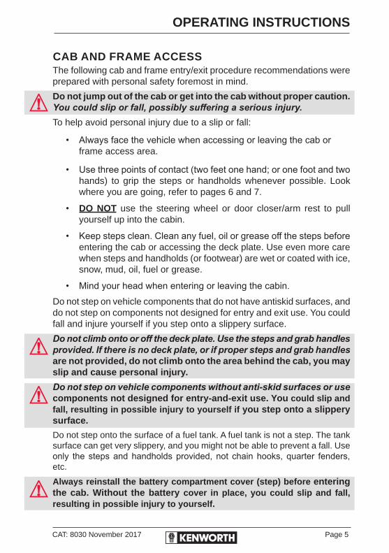
CAB AND FRAME ACCESSThe following cab and frame entry/exit procedure recommendations were prepared with personal safety foremost in mind.
Do not jump out of the cab or get into the cab without proper caution. You could slip or fall, possibly suffering a serious injury.To help avoid personal injury due to a slip or fall:
• Always face the vehicle when accessing or leaving the cab or frame access area.
• Use three points of contact (two feet one hand; or one foot and two hands) to grip the steps or handholds whenever possible. Look where you are going, refer to pages 6 and 7.
• DO NOT use the steering wheel or door closer/arm rest to pull yourself up into the cabin.
• Keep steps clean. Clean any fuel, oil or grease off the steps before entering the cab or accessing the deck plate. Use even more care when steps and handholds (or footwear) are wet or coated with ice, snow, mud, oil, fuel or grease.
• Mind your head when entering or leaving the cabin.Do not step on vehicle components that do not have antiskid surfaces, and do not step on components not designed for entry and exit use. You could fall and injure yourself if you step onto a slippery surface.
Do not climb onto or off the deck plate. Use the steps and grab handles provided. If there is no deck plate, or if proper steps and grab handles are not provided, do not climb onto the area behind the cab, you may slip and cause personal injury.
Do not step on vehicle components without anti-skid surfaces or use components not designed for entry-and-exit use. You could slip and fall, resulting in possible injury to yourself if you step onto a slippery surface.
Do not step onto the surface of a fuel tank. A fuel tank is not a step. The tank surface can get very slippery, and you might not be able to prevent a fall. Use only the steps and handholds provided, not chain hooks, quarter fenders, etc.
Always reinstall the battery compartment cover (step) before entering the cab. Without the battery cover in place, you could slip and fall, resulting in possible injury to yourself.

Page 6 CAT: 8030 November 2017
OPERATING INSTRUCTIONS
Maintain three points of contact at all times. Using the external cab access grab rails and steps to climb up into a conventional cabin. Use the external grab rail and internal access handle to aid ingress and egress to the cabin. DO NOT use the steering wheel or door closer/arm rest to pull yourself up into the cabin.
4 5 6
1 2 3

CAT: 8030 November 2017 Page 7
OPERATING INSTRUCTIONS
Extend the ACTIVE STEP (optional) by means of switches provided, refer page 8. Maintain three points of contact at all times. Using the vertical cab access grab rails and steps to climb up into a K200. Use the horizontal (overhead) grab rail and internal access handle to aid ingress and egress to the cabin. DO NOT use the steering wheel or door closer/arm rest to pull yourself up into the cabin.
1 2 3
4 5 6
Vertical Cab Access Grab Rails
Horizontal Cab Access Grab Rail
Internal Cab Access Handle on “A” Pillar
Page 8 CAT: 8030 November 2017
OPERATING INSTRUCTIONS
ACTIVE CAB ENTRY (ACE)INTRODUCTION
Active Cab Entry (optional on K200) is designed to improve driver access on the K200 cab. Users can control the system to extend the step when entering or exiting the cab and retract it after entering the cab.
• Check truck parking status and surrounding condition before using the system.
• Close step fully before moving the truck.
• ACE will not operate until the park brake has been engaged.
• Do not stand or step on the moving step; the step is not a lifting device.
• Do not touch the step or place hands between the step and truck when the step system is in motion.
• Use the step only for ingress and egress of the cab once the ACE completes its operation.
• If the battery is disconnected or removed, the system is disabled and cannot be used.
BEFORE YOU START
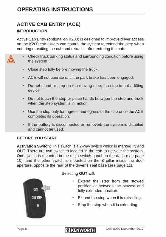
Activation Switch: This switch is a 2-way switch which is marked IN and OUT. There are two switches located in the cab to activate the system. One switch is mounted in the main switch panel on the dash (see page 10), and the other switch is mounted on the B pillar inside the door aperture, opposite the rear of the driver’s seat base (see page 11).
Selecting OUT will:
• Extend the step from the stowed position or between the stowed and fully extended position.
• Extend the step when it is retracting.
• Stop the step when it is extending.
CAT: 8030 November 2017 Page 9
OPERATING INSTRUCTIONS
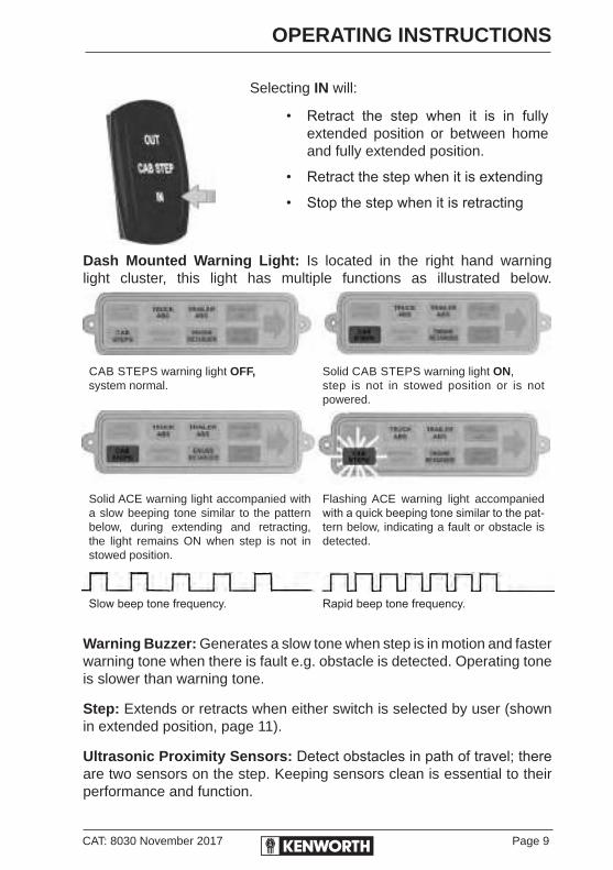
Selecting IN will:
• Retract the step when it is in fully extended position or between home and fully extended position.
• Retract the step when it is extending
• Stop the step when it is retracting
Dash Mounted Warning Light: Is located in the right hand warning light cluster, this light has multiple functions as illustrated below.
CAB STEPS warning light OFF, system normal.
Solid CAB STEPS warning light ON, step is not in stowed position or is not powered.
Solid ACE warning light accompanied with a slow beeping tone similar to the pattern below, during extending and retracting, the light remains ON when step is not in stowed position.
Flashing ACE warning light accompanied with a quick beeping tone similar to the pat-tern below, indicating a fault or obstacle is detected.
Slow beep tone frequency. Rapid beep tone frequency.
Warning Buzzer: Generates a slow tone when step is in motion and faster warning tone when there is fault e.g. obstacle is detected. Operating tone is slower than warning tone.
Step: Extends or retracts when either switch is selected by user (shown in extended position, page 11).
Ultrasonic Proximity Sensors: Detect obstacles in path of travel; there are two sensors on the step. Keeping sensors clean is essential to their performance and function.
Page 10 CAT: 8030 November 2017
OPERATING INSTRUCTIONS
OBSTACLE DETECTION
This function will be slightly different between extension and retraction. During step extending, the outside facing ultrasonic proximity sensor will monitor for obstacles. Operation of the step will be interrupted if anything is in the detection range of extending (outside), ultrasonic proximity sensor.
For step retracting, the inboard ultrasonic proximity sensor will check for obstacles within the range only when the step is fully extended, and if nothing is detected, the step will retract to the home position. The sensor will not stop the step after it leaves the fully extended position.
If an obstacle is detected, the step operation will stop and a buzzer alarm and flashing warning light will be activated. Check the step surrounding and make sure it is safe before next operation.
Make sure the park brake is engaged and check the step warning light status before using ACE.
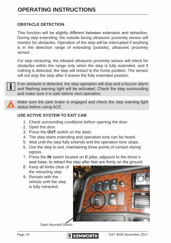
USE ACTIVE SYSTEM TO EXIT CAB
1. Check surrounding conditions before opening the door.2. Open the door.3. Press the OUT switch on the dash.4. The step starts extending and operation tone can be heard.5. Wait until the step fully extends and the operation tone stops.6. Use the step to exit, maintaining three points of contact during
egress.7. Press the IN switch located on B pillar, adjacent to the driver’s
seat base, to retract the step after feet are firmly on the ground.8. Keep all limbs clear of
the retracting step.9. Remain with the
vehicle until the step is fully retracted.
Dash Mounted Switch

CAT: 8030 November 2017 Page 11
OPERATING INSTRUCTIONS
USE ACTIVE SYSTEM TO ENTER CAB
1. Check surrounding conditions before opening the door.
2. Open the door.3. Press the OUT switch located on
B pillar adjacent to the driver’s seat base.
4. The step starts extending and an operation tone can be heard.
5. Wait until the step fully extends and the operation tone stops.
6. Use the step to enter the cab, maintaining three points of contact during ingress.
7. Check step area is clear, press the IN switch on dash to retract the step after entering the cab.
8. Wait for the step to fully retract before releasing the park brake.
B Pillar Mounted Switch
Proximity Sensor mounted center of step
Extended Step
Proximity Sensor mounted center, inboard of the step

Page 12 CAT: 8030 November 2017
OPERATING INSTRUCTIONS
ENGINE ACCESSBefore opening the hood, remove any tow hitches from the bumper bar.
CONVENTIONAL HOOD HOLD-DOWNSThe hood is locked in position by two or four external latches. These latches serve as hold-downs and keep the hood from opening unexpectedly.
Hood Tilt (Conventional Cabs)To open the hood, if a bullbar is fitted, tilt bullbar forward, unhook the hood hold-down latches and grip on the KW emblem on the front of the hood. Place foot firmly on the aluminium step on the bumper, to create leverage, and pull the hood slowly forward until it stops. Attach the cable over the hook on the inner hood spider to secure the hood,
Never work under the hood unless it is securely locked, using the safety cable. If the hood falls anyone under it could be injured. Always lock the hood in its open position any time anyone gets under the hood.

CAT: 8030 November 2017 Page 13
OPERATING INSTRUCTIONS
If the hood is not securely latched it could open during operation and cause an accident. Be sure the hood is securely latched before moving the vehicle.
The hood could hurt anyone in the way of its descent. Before lowering the hood be sure no objects or people are in the way.
Do not work on or near the fan with the engine running. Anyone near the engine fan when it turns on could be seriously injured. If it is set at MANUAL the fan will turn on any time the ignition key switch is turned to the ON position.
In AUTO it could engage suddenly without warning. Before turning on the ignition or switching from AUTO to MANUAL, be sure no one is near the fan.
Attached cable
Hood Assist Spring
Page 14 CAT: 8030 November 2017
OPERATING INSTRUCTIONS
K200 ENGINE ACCESS
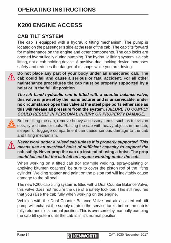
CAB TILT SYSTEMThe cab is equipped with a hydraulic tilting mechanism. The pump is located on the passenger’s side at the rear of the cab. The cab tilts forward for maintenance on the engine and other components. The cab locks are opened hydraulically during pumping. The hydraulic lifting system is a cab lifting, not a cab holding device. A positive dual locking device increases safety and reduces the danger of mishaps while you are driving.
Do not place any part of your body under an unsecured cab. The cab could fall and cause a serious or fatal accident. For all other maintenance procedures the cab must be properly supported by a hoist or in the full tilt position.
The left hand hydraulic ram is fitted with a counter balance valve, this valve is pre-set by the manufacturer and is unservicable, under no circumstance open this valve at the steel pipe ports either side as this will release all pressure from the system, FAILURE TO COMPLY COULD RESULT IN PERSONAL INJURY OR PROPERTY DAMAGE.Before tilting the cab, remove heavy accessory items, such as television sets, tyre chains or tools. Raising the cab with heavy objects in the cab, sleeper or luggage compartment can cause serious damage to the cab and tilting mechanism.
Never work under a raised cab unless it is properly supported. This means use an overhead hoist of sufficient capacity to support the cab safely. Never prop the cab up instead of using a hoist. The prop could fail and let the cab fall on anyone working under the cab.When working on a tilted cab (for example welding, spray-painting or applying bitumen coatings) be sure to cover the piston rod of the lifting cylinder. Welding spatter and paint on the piston rod will inevitably cause damage to the oil seal.
The new K200 cab tilting system is fitted with a Dual Counter Balance Valve, this valve does not require the use of a safety lock bar. This still requires that you raise the cab fully when working on the engine.
Vehicles with the Dual Counter Balance Valve and air assisted cab tilt pump will exhaust the supply of air in the service tanks before the cab is fully returned to its normal position. This is overcome by manually pumping the cab tilt system until the cab is in it’s normal position.

CAT: 8030 November 2017 Page 15
OPERATING INSTRUCTIONS
When raising and lowering the cab, using either method of Air Assist or Manual, it is recommended that the operation is carried out with minimum interuption, releasing and applying pressure to the cab tilt system in a stop/go manner, causes the cab to react in a jerky motion
The cab tilt system is designed that in the unlikely circumstance of a flexible wire braid hose was to burst for any reason the cab tilt system would lock up in the position it is in at the time of the burst.
The only way to release this is to replace the hose and bleeding the line that has been repaired, if the cab is in a semi raised position, make sure you secure the cab by using an overhead crane or lifting device, do not get under the cab until it is secure.
Inspection after a collisionBefore tilting the cab after a collision, check the cab rests, the cab hinges and the attachment of the lifting cylinders to the chassis member and cab for cracks.
If the vehicle has been involved in a collision, the cab must under no circumstances be tilted without due precautions. The end stop in the lifting cylinder may be damaged, which might cause the cab to shoot past its end stop.
If possible, suspend the cab in slings and put a stand in front of the cab. Make sure that there is no one in front of the cab while it is being tilted.
Replacing the lifting cylindersAfter a collision, always check the lifting cylinders for internal damage. Replace the lifting cylinders if they are damaged or if you are in doubt as to their condition. Always replace the cylinders if one of the following points has occurred during a collision:
A. the cab has been pulled out of the cab locks,
B. the cab locks have been deformed or damaged,
C. the rear cab suspension has been deformed or damaged.

Page 16 CAT: 8030 November 2017
OPERATING INSTRUCTIONS
HOW TO RAISE AND LOWER THE CAB
TO RAISE THE CAB1. Place Gearshift in Neutral Position.2. Lower Bullbar if fitted.
3. Turn the three-way valve (E) on the pump (A) anticlockwise (see page 17) to the “Raise” position.
4. Release the mechanical safety lock on left hand rear support, by pulling the handle towards you.
Mechanical safety lock on left hand rear support must be released before it touches the underside of the cab latch mounting bracket.
5. Push air assist button to raise cab, optional, insert handle and pump cab up manually.
6. Valve must be in this “Neutral” position when not in use.
TO LOWER THE CAB1. Turn the three-way valve (E) on the pump (A) clockwise (see page
17) to the “Lower” position.
2. Push air assist button to raise cab, optional, insert handle and pump cab down manually.
3. An audible click is heard as the safety lock engages.
4. Ensure Hydraulic catches engage on both sides.
5. Move the pump control lever (E) from lower to raise and back to lower, repeat this process until the pressure is relieved from the system, a sound will be heard and the lever (E) will become easy to move, return the lever to the neutral position. Valve must be in this “Neutral” position when not in use.
6. Raise Bullbar if fitted.

CAT: 8030 November 2017 Page 17
OPERATING INSTRUCTIONS
LOWER RAISE
NEUTRAL
Detail of Pump Control Lever (E)
PUSH
PULL
RAISE
A
EF
DD
G15-1007 Rev. 0
3
4
C
5
43
5
1
2
BB
Legend
Raise Cab/Extend Rams - Dark Lines
Lower Cab/Retract Rams - Light Lines
A. Hydraulic PumpB. Cab LatchesC. Dual Counter Balance ValveD. Cab Tilt CylindersE. Pump Control LeverF. Air Assist Button

Page 18 CAT: 8030 November 2017
OPERATING INSTRUCTIONS
GENERAL MAINTENANCEOil, specifications, level & service:
1. Use a proprietary hydraulic fluid (Kenworth Trucks installs and recommends Castrol TQ Dexron III). This is a constant viscosity fluid, required to ensure consistent operation of the system.
Do not use brake fluid.2. Check the level of hydraulic fluid in the reservoir at regular intervals.
Keep the reservoir filled to the top at all times.Never fill the reservoir with the cab in the raised position.
3. Periodically inspect the components, hydraulic lines, and connections for damage or loss of hydraulic fluid.
REMOVING EXCESS AIR FROM THE SYSTEM:
To remove air from pump piston:Air in the pump piston is indicated by spongy response when exerting pressure on the pump handle.
1. Open the release valve or place the valve in travel (lower cab) position.
2. Actuate pump rapidly by hand. Air in piston will return to reservoir.
To remove air from double acting cylinder:1. With cylinder in retracted position and cab down in lock position,
open Pull port fittings slightly and place valve in Lower position.
2. Actuate hand pump or air pump until oil without aeration flows from the cylinder ports.
3. Tighten Pull port fittings at cylinders.
4. Loosen Push port fittings at cylinder and place valve in the up position.
5. Actuate hand pump or air pump until solid oil (no air bubbles) appears at loose push fittings at cylinder.
6. Tighten Push port fittings at cylinder.
CAT: 8030 November 2017 Page 19
OPERATING INSTRUCTIONS
7. Refill pump reservoir with cab in down position until oil flows from fill port.
8. Actuate cab, tilt fully to 90°, and return to down position.
9. Refill reservoir, if necessary, after fully tilting to 90° and returning to down position.
SYSTEM CONTAMINATION1. All cylinders have screens at their ports. If dirt appears at a screen
or the screen appears clogged, use a small pick or sharp tool to remove accumulated dirt from the screen.
2. All pumps have screens on their inlet ports inside the reservoir. Remove the reservoir if no oil will go through the pump and clean the inlet screen. Replace reservoir, refill and bleed hoses.
3. All pumps have No. 50 mesh screens, sometimes called top hat screens, which are held in place by wire rings at the Pull and Push ports of each valve. Check to ensure that no accumulated dirt has plugged these screens. Use a small pick or sharp tool to remove accumulated dirt in a screen.
Air, dirt and lack of oil account for seventy-five percent of all hydraulic problems.
Page 20 CAT: 8030 November 2017
OPERATING INSTRUCTIONS
SAFE VEHICLE OPERATIONFor your safety, as well as that of those around you, be a responsible driver:
• If you drink, do not drive. It is illegal to do so.
• Do not drive if you are tired, ill, or under emotional stress.Much has gone into the manufacturing of your Kenworth truck including advanced engineering techniques, rigid quality control and demanding inspections. These manufacturing processes will be enhanced by a safe driver – one who:
• Knows and understands how to operate the vehicle and all its controls.
• Maintains the vehicle properly.
• Uses driving skills wisely.
VEHICLE LOADINGCompare your vehicle’s load capacity with the total load you are carrying. If adjustments need to be made, make them. Do not drive an overloaded vehicle. If you are overloaded or your load has shifted, your vehicle may be unsafe to drive.
Gross Vehicle Mass (GVM) is the maximum allowable total mass of a fully loaded motor vehicle, consisting of the tare mass (mass of the vehicle) plus the load including occupants and fuel.
Gross Combination Mass (GCM) When a vehicle is towing one or more trailers, the GCM is the total mass of the motor vehicle plus any, and all trailers including load, occupants and fuel.
Do not exceed the specified load rating. Overloading can result in loss of vehicle control and personal injury, either by causing component failures or by affecting vehicle handling. Exceeding load ratings can also shorten the service life of the vehicle.
The components of your vehicle are designed to provide satisfactory service if the vehicle is not loaded in excess of either the gross vehicle mass rating (GVM) and/or gross combination mass rating (GCM) and/or the maximum front and rear gross axle weight ratings.

CAT: 8030 November 2017 Page 21
OPERATING INSTRUCTIONS
An unevenly distributed load or a load too heavy over one axle can affect the braking and handling of your vehicle, which could result in an accident. Even if your load is under the legal limits, be sure it is distributed evenly.
EMERGENCY EQUIPMENTIt is good practice to carry an emergency equipment kit in your vehicle. If you have a roadside emergency you will be glad the following items are with you:
• Emergency light
• Emergency reflector triangles
• First aid kit
• Fire extinguisher
DRIVER’S CHECKLISTTo keep your Kenworth truck in top shape and maintain a high level of safety for you, your passengers and your load, make a thorough inspection every day before you drive. You will save maintenance time later, and the safety checks could help prevent a serious accident.
You are not expected to become a professional mechanic. The purpose of your inspections is to find anything that might interfere with the safe and efficient transportation of yourself, any passengers and your load. If you do find something wrong and cannot fix it yourself, have an authorised Kenworth dealership or qualified mechanic repair your vehicle right away.The operations on the following pages are to be performed by the driver.
Performing these checks and following the maintenance procedures in this handbook will help keep your Kenworth truck running properly.
Page 22 CAT: 8030 November 2017
OPERATING INSTRUCTIONS
IMPORTANTIt is recommended that you have an engine start-up inspection performed within the first 90 days of operation. The inspection may be performed at any service shop authorised by the engine manufacturer.
NEW VEHICLE PRECAUTIONSOil changes: Engine, Transmission and Driving Axles
The initial factory lubricants must be drained and the units refilled at the first 10,000 km or 30 days service.Transmissions RTLO 20918 and larger MUST have the mineral oil replaced with synthetic oil at the First Service.
APPROACHING YOUR VEHICLE• Check the overall appearance and condition. Are windows, mirrors
and lights clean and unobstructed?
• Check beneath the vehicle. Are there signs of fuel, oil or water leaks?
• Check for damaged, loose or missing parts. Are there parts showing signs of excessive wear or lack of lubrication? Have a qualified mechanic examine any questionable items and repair them without delay.
• Check your load. Is it secured properly?

CAT: 8030 November 2017 Page 23
OPERATING INSTRUCTIONS
DAILY CHECKS
ENGINE COMPARTMENT1. Engine fluid levels
• Engine oil.
• Coolant (check while engine is cold).
• Power steering fluid level.
2. Engine Belt
• Check tension and condition of belts.
• If breaks or tears are found, the belt should be replaced before operating the vehicle.
Deflection should be one belt thickness for each 30cm distance between the pulley centres.
3. Fuel Filter/Water Separator Draining - check and drain. Depending on the fuel storage facility, more frequent draining may be required.
4. Windshield washer reservoir fluid level.
5. Hood closed before entering cab. Is it latched properly?
CHASSIS AND CABBefore entering the cab and operating the vehicle, check the following equipment for proper maintenance:
1. Lights - Check headlights, turn signals, emergency flashers and exterior lamps function and are clean and adjusted properly.
2. Windows and Mirrors - Are they clean and adjusted properly?
3. Tyres and Wheels - Are tyres inflated properly? Are all wheel nuts in place and torqued properly? Tighten if necessary. Check front wheel bearing oil levels. Inspect aII tyres and wheels for damage. Correct if found.
4. Suspension - Check for loose or missing fasteners. Check damage to springs or other suspension parts.
Page 24 CAT: 8030 November 2017
OPERATING INSTRUCTIONS
5. Brake Components - Check lines, linkages, chambers, parking and service brake operation.
6. Air System - Are there leaks?
• Air Tanks - Drain water from all air tanks. Make sure the drain cocks are closed. This procedure is also required for air suspension tanks equipped with automatic drain valves.
• See page 99 for further details on Brakes.Failure to drain air tanks every day may allow water, oil and dirt to be passed through the air system. This can result in malfunctioning valves, which will affect the proper and safe operation of your vehicle.
7. Steps and Handholds - Check for worn surfaces and loose or missing fasteners.
8. Fluid Tanks - Check under the vehicle for signs of leaks. If any are found, correct them before operating the vehicle.
9. Fuel Tank Caps - Are they secure?
Diesel fuel in the presence of an ignition source (such as a cigarette) can cause an explosion. You could be seriously injured.
Do not remove a fuel tank cap near an open flame. Use only the fuel and/or additives recommended for your engine. See Refuelling page 140 for more information.
10. Trailer Connections (Truck) - Are they secure and the lines clear? If they are not being used, are they stored properly?
• Is the trailer spare wheel secure and inflated?
• Is the landing gear up and the handle secured?
• Check the fifth wheel. Is the kingpin locked?
11. Is the sliding fifth wheel locked?
12. Is the greasable fifth wheel properly greased?
CAT: 8030 November 2017 Page 25
OPERATING INSTRUCTIONS
PRE-START CHECKS
DAILY OPERATIONS1. Drain moisture from the air tanks. Open the tank drains just enough
to drain the moisture. Do not deplete the entire air supply. Doing this at the start of the day, ensures any moisture from the previous day is ejected fom the air tanks.
2. Fuel - Check fuel. Is there enough fuel?
3. Seat - Adjust the seat to ensure controls are easily reached.
4. Seatbelts - Fasten and adjust safety restraint belts.
5. Sleeper Restraints - Check and inspect condition.
6. Steering Column - Adjust for easy reach.
7. Mirrors - Check and readjust mirrors if necessary.
8. Lights - Turn ignition key to the ON position and check for warning lights and buzzer. Check operation of turn signals and emergency lights.
9. Instruments - Check all instruments.
10. Windshield - Check operation of windshield wipers and washers.
11. Horn - Check operation of horn.
12. Sleeper and Luggage Compartment - Loose items should be stowed securely. Is the fire extinguisher fully charged? Is your road emergency kit complete? Are all external compartments closed?
The above items (Engine Compartment, Chassis and Cab, and Pre-start Checks) should be undertaken daily, as a minimum. This is in addition to, not instead of, your normal maintenance checks.
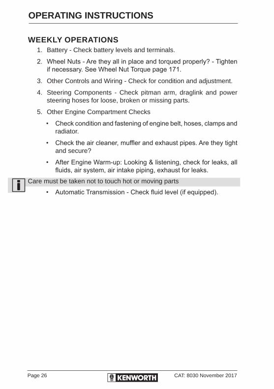
Page 26 CAT: 8030 November 2017
OPERATING INSTRUCTIONS
WEEKLY OPERATIONS1. Battery - Check battery levels and terminals.
2. Wheel Nuts - Are they all in place and torqued properly? - Tighten if necessary. See Wheel Nut Torque page 171.
3. Other Controls and Wiring - Check for condition and adjustment.
4. Steering Components - Check pitman arm, draglink and power steering hoses for loose, broken or missing parts.
5. Other Engine Compartment Checks
• Check condition and fastening of engine belt, hoses, clamps and radiator.
• Check the air cleaner, muffler and exhaust pipes. Are they tight and secure?
• After Engine Warm-up: Looking & listening, check for leaks, all fluids, air system, air intake piping, exhaust for leaks.
Care must be taken not to touch hot or moving parts
• Automatic Transmission - Check fluid level (if equipped).

CAT: 8030 November 2017 Page 27
OPERATING INSTRUCTIONS
OPERATING TEMPERATURES*Engine Oil
Normal Operating Range
Maximum for short periods of time at full load.
Refer to Engine Manufacturer’s Manual
Refer to Engine Manufacturer’s Manual
Engine CoolantNormal Operating Range
High Coolant temperature warning light comes on at:
Refer to Engine Manufacturer’s Manual
Refer to Engine Manufacturer’s Manual
Rear Axle LubricantNormal Operating RangeMaximum difference between axlesClimbing steep gradesMaximum allowable (investigate cause)
79°C–107°C17°C107°C121°C
Transmission LubricantNormal Operating RangeMaximum (investigate cause)
**66°C–93°C149°C (intermittently)121°C (continuously)
* Refer to your engine manual for specific operating range.** For rear axle and transmission, operating at higher temperatures is permissible for
short periods. When operation occurs at these higher temperatures, the oil must be changed more frequently. Do not continuously operate with oil temperature exceeding 121°C. At these temperatures, oil oxidation is accelerated.
OPERATING PRESSURES*Engine Oil Refer to the Engine
Manufacturer’s Manual
Air SystemAir Governor RangeLow Pressure warning light indicatorSafety Blow-off ValveStop Light Switch actuates at
690–827 kPa414–482 kPa
1034 kPa34.5 kPa
Spring BrakesBrake Hold off pressure (depending on brake installation) 414–482 kPa
Power SteeringPump Relief valve pressure (refer maintenance manual)Pump Pressure is dependent on pump and box combination.
12,065 kPa TAS 85
14,830 kPa TAS 65
*Refer to your engine manual for specific operating range.

Page 28 CAT: 8030 November 2017
OPERATING INSTRUCTIONS
INSTRUMENTS AND CONTROLSThis section explains the location and function of the various instruments and controls in your vehicle.
INSTRUMENT PANELPlease remember that each Kenworth truck is custom-built. For this reason, your instrument panel may not look exactly like the one in the illustrations. In this handbook, we describe the most common instruments and controls available, however many of these are options.
ADJUSTABLE STEERING COLUMN
Never adjust your steering column when the vehicle is in motion. Loss of steering may cause an accident.
Column Angle Adjustment• Pull lever (7) on left side of steering column.• Adjust column angle when holding lever.• Release lever (7) and check that it is in the
fully down position, assuring proper locking.
Height and Tilt Adjustment• Push or pull to adjust height of steering
wheel.
• Pull lever (7) up to adjust height, push lever down to adjust tilt.
Use of excessive force to lock may create difficulties with further adjustments.
6
15 4 3 2
7
0
III
NOT FOR PARKING
Steering Column Controls1 Trailer Brake
2 High Beam On/Off (pull to operate)
3 Windscreen Wipers (twist)
4 Indicator (move in direc-tion of arrows)
5 Windscreen Wash (push in)
6 Electric Horn Button (push)
7 Column Adjust
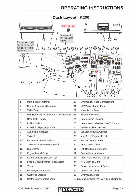
CAT: 8030 November 2017 Page 29
OPERATING INSTRUCTIONS
Dash Layout - K200
X
X
X
X
X
X
1
32
0
0
OFF
A/C
KW
+
+
+
+
FLOOD
LIGHTS
DRIVING
LIGHTS
DOME
LAMP
FOG
LIGHTS
LOADING
LIGHT
OOO
IIIBEACON
LIGHTS
ENGINE
FAN
HAZARD
LIGHTS
VOLUME
HANDSET
01
HOURS
0 0 0 0 0
VDO
12
3
6
9
VDO
50
100 120
150
AXLE OIL
FRT RR
CO
50
100 120
150
AXLE OIL
REAR RR
CO
0
10
20
30
40
AIR
FILTER
in H2O vac
AIR
RESTRICTION
2
4 6
8
100
KPa x 100
AIR
SUSPENSION
AIR PRESS
0
200
400 600
800
1000
Kpa
FRONTAIR
0
200
400 600
800
1000
Kpa
REARAIR
PARKING
BRAKE
RELEASE
PU
LL
TO EXHA
U
ST
TRAILERAIR SUPPLY
NOTFOR
PARKING
PARKING
BRAKEPUSH TO
RELEASE
P
US
HTO SU
P
PL
Y
0
RPM x100
VDO
25
5 20
1510
HOURS
STOP
ENGINE CRUISE
ENABLE
CHECK
ENGINE
TRAILER
TURN
GEARBOX
PRESSUREWASHER
LOW
ENGINE
MAINT
ALTNTR
ISOLATED
MAR2012
0
20
4060
80
100
120
Km/h
VDO
SUSPENSION
DUMP
COOLANT
LEVEL
BRAKE
LOW AIR
OIL
PRESS
REVERSE
COOLANT
TEMP
TRUCK
ABS
TOOLBOX
OPEN
PARK
BRAKE TRAILER
AIR
INTERAXLE
LOCK
FASTEN
SEAT BELT
MIRROR
HEATHI
BEAM
TRAILER
ABS
ENGINE
RETARDER
0
200400 600
800
1000
DEGREESC
PYROMETER
LIGHTS O
.5 2 4
1 3 5
TURBO
TIMER
TRAILER
PARK
BRAKE
RELEASE
TRAILERRELEASE
VALVE
ENGDIAG
ABSDIAG
PANEL DIMMER
DOWN
LOWER
UP
LOCK
DIFF
LOCK
UNLOCK
RR
LOCK
DIFF
LOCK
UNLOCK
FR
LOCK
INTER
AXLE
UNLOCK
01 2
34
FUEL
FUEL LEVELFUEL LEVEL
VOLT
810
12 1416
VOLT METERVOLT METER
0
250
500
Kpa
ENG OIL
PRESS
40
80 100
120
CO
ENG WATER
TEMP
ATC OFF
ROAD
50
100 120
150
CO
ABS OFF
ROAD
100
200
300
4000
kPa
START
STOP
START
STOP
I
O
23 27 292017 18 19 21 22 26 31 3225 33
37
28
36
30 34
16 1415
24
9
8 6
5
4 2
13
10
1113
12
35
7
1 Main Instrument Panel 20 Overhead Storage Compartment
2 Engine Diagnostic Connector 21 12V Power Supply Point
3 Turbo Timer 22 Main Switch Panel
4 DPF Regeneration Switch & Status Display 23 Bluetooth Switches
5 Head Light Switch 24 Spare Switch Location
6 Ignition Switch 25 Heater/Air-conditioner (HVAC) Controls
7 AutoShift Display (optional) 26 AM/FM Radio/CD Player
8 Audio warning Buzzer 27 Location for Extra Gauges
9 Trailer Air 28 Inter Axle Differential Lock
10 Instrument Dimmer Switch 29 Suspension Air Dump
11 Trailer Release Valve (Optional) 30 ABS Warning Light
12 System Park 31 Left Hand Warning Cluster
13 Engine Tunnel Cover 32 Centre Warning Cluster
14 Centre Console Storage Tray 33 Right Hand Warning Cluster
15 Fuse & Circuit Breaker Panel Access 34 ATC Warning Light
16 Vents 35 Engine Management System
17 Passenger’s Sun Visor 36 Driver’s Sun Visor
18 Overhead Storage 37 Overhead Storage
19 Centre Sun Visor (optional) Gauges and switches may vary from illustration
R e m o v e t h i s cover to access fuses & circuit breakers
Remove this tray to access relays

Page 30 CAT: 8030 November 2017
OPERATING INSTRUCTIONS
Conventional Dash Layout
1 Hazard Warning Light Switch 19 Switch Panel Lights
2 DPF Regeneration Switch & Status Display 20 USB Port
3 Right Hand Warning Cluster 21 Fuse & Relay Access Cover
4 Main Instrument Panel 22 Cab Access Hand Rails
5 Head Light Switch 23 HVAC Vents
6 Turbo Timer 24 Location for CB & UHF Radios
7 Instrument Dimmer Switch 25 Second Gauge Panel
8 Fan Switch 26 First Gauge Panel
9 Ignition Switch 27 FM/AM Radio/CD Player A Road Relay
10 Centre Warning Cluster 28 ABS, HSA Switches and Warning Lamps
11 Left Hand Warning Cluster 29 AutoShift Display (Optional)
12 Trailer Release valve (optional) 30 Speakers (Tweeters)
13 Suspension Air Dump & Diff Locks Switches 31 Utility Lights (Optional)
14 Trailer Air 32 Overhead Storage
15 Truck Park Brake 33 Sunvisors
16 Heater/Air-conditioner (HVAC) Controls 34 Overhead Console
17 Gear Lever “CobraShift” Gauges & Switches my vary from illustration
18 Power Socket
TX4500GME
TX2720GME
01 2
34
FUEL
FUEL LEVEL
VOLT
810
12 1416
VOLT METERVOLT METER
FUEL LEVEL
0
200
400 600
800
1000
Kpa
0
200
400 600
800
1000
Kpa
800
1000
PYROMETER
0
200400
600
DEGREES C
Brambles
0
20
4060
80
100
120
Km/h
VDO
0
RPM X 100
VDO
255
20
15
10
30Hour Meter
MMXIV
0
20
4060
80
100
120
Km/h
VDO
0
RPM X 100
VDO
255
20
15
10
30Hour Meter
BRAKE
LOW AIR
OIL
PRESS
REVERSE
COOLANT
PARK
BRAKE
TRAILER
AIR
MIRROR
HEAT
HIGH
BEAM
STOP
ENGINE
INTERAXLE
LOCK
CHECK
ENGINE
ENGINE
FAN
GEARBOX
PRESSURE
AFTER
TREAT
ALT
TRAILER
ABS
ENGINE
RETARDER
DOOR
OPEN
CRUISE
ENABLE
PTO
TRUCK
ABS
CAB
STEPS
SUSPENSION
DUMP
ESC
.5 2 4
1 3 5
TURBO
TIMER
PU
LL
TO E XHAU
ST
TRAILERAIRSUPPLY
NOTFOR
PARKING
P
US
HTO SU
P
PL
Y
TRAILERRELEASE
VALVE
1 3
2
00
OFF
A/C
KW
+
+
+
+
0
250
500
Kpa
ENG OIL
PRESS
40
80 100
120
CO
ENG WATER
TEMP
ATC
ABS OFF
ROAD
STOP
ENGINE
PARKING
BRAKE
RELEASE
PARKING
BRAKEPUSH TO
RELEASE
01
HOURS
0 0 0 0 0
VDO
12
3
6
9
VDO
50
100 120
150
AXLE OIL
FRT RR
CO
50
100 120
150
AXLE OIL
REAR RR
CO
0
10
20
30
40
AIR
FILTER
in H2O vac
AIR
RESTRICTION
2
4 6
8
100
KPa x 100
AIR
SUSPENSION
AIR PRESS
01
HOURS
0 0 0 0 0
VDO
50
100 120
150
AXLE OIL
FRT RR
CO
50
100 120
150
AXLE OIL
CTR RR
CO
50
100 120
150
AXLE OIL
REAR RR
CO
ATTENTIONALL ENGINE WARNING
LAMPS MUST BE OFF
BEFORE STARTING ENGINE
REARAIR
FRONTAIR
START
STOP
START
STOP
LIGHTS O
HAZARD
LIGHTS
DRIVING
LIGHTS
ENGINE
FAN
HAZARD
LIGHTS
I
O
DIM
BRIGHT
FAN
1
2
3
4
5
6
21 20 19 18 17 16 15 14 13 12 11 10 9 8 7
22
23 24 25 26 27 28 29
30 31 32 33 34 33 32 31 30

CAT: 8030 November 2017 Page 31
OPERATING INSTRUCTIONS
WARNING LIGHTS
Warning Light ClustersThe standard indicator cluster contains the LH and RH turn signal indicators and the headlight high beam indicator.
Left-hand Cluster
Centre Cluster
Right-hand Cluster
Functional DescriptionWarning lamps that are lit may indicate something is wrong with that system or that the system is turned on. Check the lamps frequently and respond properly as soon as a lamp or buzzer comes on.
Do not ignore a warning light or buzzer. These signals may tell you something is wrong with your vehicle. It could be a failure in an important system, such as the brakes, which could lead to an accident. Have the appropriate system checked immediately. Whenever the ignition switch is in the ON position (engine not running) the Low Oil, Park Brake and Low Air Pressure warning lights will be on.
Check Engine – This lights when a problem exists, but the vehicle can still be safely driven. Vehicle should be serviced to correct the problem as soon as conveniently practical, but the situation should not be considered an emergency.
OIL
PRESS
REVERSE
COOLANT
PARK
BRAKE
TRAILER
AIR
MIRROR
HEAT
HIGH
BEAM
STOP
ENGINE
INTERAXLE
LOCK
CHECK
ENGINE
ENGINE
FAN
GEARBOX
PRESSURE
AFTER
TREAT
ALT
TRAILER
ABS
ENGINE
RETARDER
DOOR
OPENESC
CRUISE
ENABLE
PTO
TRUCK
ABS
CAB
STEPS
SUSPENSION
DUMP
BRAKE
LOW AIR

Page 32 CAT: 8030 November 2017
OPERATING INSTRUCTIONS
Stop Engine – This lights when a major engine-system problem exists. The driver should stop the vehicle as soon as safely possible and have the fault repaired before driving the vehicle again. This should be considered an emergency. The vehicle must be repaired and the problem corrected before continuing.
ABS (Antilock Braking System (Optional)) – This lights when ignition is switched ON and stays lit for a short time. If ON at any other time during vehicle operation, it signals a fault in the Antilock Brake System.
If the Lamp Warning Module buzzer sounds while driving, or if one of the red lights comes on, indicating a failure has occurred in an important system, follow the procedure below:
1. Slow down carefully.
2. Move a safe distance off the road and stop.
3. Set the parking brake.
4. Turn on the emergency flasher and use warning devices to alert other motorists (i.e. Warning Triangle).
Trailer ABS (Optional) – With trailer connected, illuminates when ignition is turned ON and stays lit momentarily dependant on trailer ABS module manufacturer. If ON at any other time during vehicle operation, it signals a fault in the trailer Antilock Brake System. If the trailer is not equipped with ABS brakes, the light will remain OFF.
POWER-ON TESTWhen the ignition switch is turned ON, some of the warning lamps illuminate initially, extinguishing in sequence. The test lets the driver know the lamps in the module are in working condition. After the test, the module enters the normal operating mode in which all input signals are monitored. If any one of them is activated, the respective lamp will turn on, giving the driver a warning or status indication.

CAT: 8030 November 2017 Page 33
OPERATING INSTRUCTIONS
SPEEDOMETER/ODOMETERThe speedometer indicates vehicle speed in kilometres per hour (km/h). The odometer, in the centre of the speedometer, has a multi-purpose function display and can be used to calibrate the speedometer. It records the kilometres your vehicle has travelled.
Km/h
VDO
80
100
120
6040
20
0 MMXV II
The trip odometer tells how many kilometres the vehicle has gone on a particular trip. To use it, press the button on the speedometer.
Starting at 0, the trip odometer will then begin to count the kilometres travelled. To start over, push the button again.
For more information on how to use this, refer to your nearest authorised Kenworth dealer.

Page 34 CAT: 8030 November 2017
OPERATING INSTRUCTIONS
TACHOURMETERThe Tachourmeter measures the engine speed in revolutions per minute (rpm). Watching the tachourmeter is important for efficient driving. It will let you match driving speed and gear selection to the operating range of your engine.
If the engine speed gets too high, you can select a higher gear to lower the rpm. If the engine speed drops too low, you can select a lower gear to raise the rpm. See page 122 for further instructions on driving techniques and using the tachourmeter. To avoid engine damage, do not let the pointer exceed maximum governed speed. (See your Engine Operation and Maintenance Manual for rpm recommendations). The Tachourmeter incorporates an Engine Hour Meter that displays the total number of hours that an engine has been run. It cannot be reset to zero.
Tachourmeter
RPM x 100
20
25
15
10
5
300
VDO
HOURMETER

CAT: 8030 November 2017 Page 35
OPERATING INSTRUCTIONS
ENGINE OIL PRESSURE GAUGEIt is important to maintain oil pressure within acceptable limits. If oil pressure drops below the minimum kPa, an oil pressure warning lamp in the LH warning light cluster will light, and the Stop Engine Lamp will come ON.
Engine Oil Pressure Gauge
For further information on engine oil and normal operating pressures, see your Engine Operation and Maintenance Manual. Continuing to operate your vehicle with insufficient oil pressure will cause serious engine damage.
If the oil pressure fails to rise within 10 seconds after the engine starts, stop the engine and determine the cause. Check the engine manufacturer’s manual for the correct oil pressure ranges for your vehicle’s engine.
If the oil pressure suddenly drops, or the audible alarm and engine oil pressure warning light come on while you are driving, follow the procedure below.
1. Slow down carefully.
2. Move a safe distance off the road and stop.
3. Place the transmission in neutral and set the parking brake.
4. Turn OFF the engine.
Turn ON the emergency flasher and use other warning devices to alert motorists.
Wait a few minutes to allow oil to drain into the engine oil sump, then check the oil level. (See Engine Manufacturer’s Handbook for details on checking oil level).
Add oil if necessary. If the problem persists, contact an authorised Kenworth service dealer.
For further information on engine gauges and operating your engine properly, see Operating the Engine on page 63.
0250
500
Kpa
ENG OILPRESS

Page 36 CAT: 8030 November 2017
OPERATING INSTRUCTIONS
ENGINE COOLANT TEMPERATURE GAUGEThe Engine Coolant Temperature Gauge indicates the temperature of the engine coolant. Under normal operating conditions, the coolant temperature gauge should register between 80°C and 103°C. Under certain conditions, somewhat higher temperatures may be acceptable. Check the engine manual for correct operating ranges.
Coolant Temperature Gauge
AIR SYSTEM PRESSURE GAUGES
Front and Rear ServiceThe air pressure gauge indicates the amount of air pressure in the brake system in kilopascals (kPa). The front air pressure gauge shows the front service tank air pressure and the rear air pressure gauge indicates pressure in the rear service tank.
0
200
400 600
800
1000
Kpa
0
200
400 600
800
1000
Kpa
FRONTAIR
REARAIR
Front Air Pressure Rear Air Pressure
Ensure the air pressure registers more than 690 kPa in both service systems before you move the vehicle.
If the pressure in either or both circuits is too low for normal brake operation, a warning light in the LH Warning Cluster will glow and the audible alarm will sound.
40
80 100
120
Co
ENG WATERTEMP
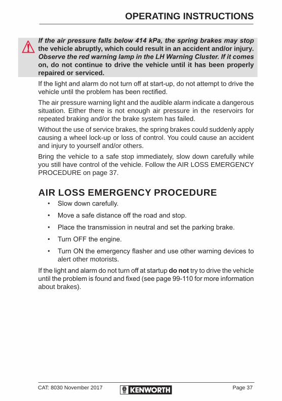
CAT: 8030 November 2017 Page 37
OPERATING INSTRUCTIONS
If the air pressure falls below 414 kPa, the spring brakes may stop the vehicle abruptly, which could result in an accident and/or injury. Observe the red warning lamp in the LH Warning Cluster. If it comes on, do not continue to drive the vehicle until it has been properly repaired or serviced.
If the light and alarm do not turn off at start-up, do not attempt to drive the vehicle until the problem has been rectified.The air pressure warning light and the audible alarm indicate a dangerous situation. Either there is not enough air pressure in the reservoirs for repeated braking and/or the brake system has failed.
Without the use of service brakes, the spring brakes could suddenly apply causing a wheel lock-up or loss of control. You could cause an accident and injury to yourself and/or others.
Bring the vehicle to a safe stop immediately, slow down carefully while you still have control of the vehicle. Follow the AIR LOSS EMERGENCY PROCEDURE on page 37.
AIR LOSS EMERGENCY PROCEDURE• Slow down carefully.
• Move a safe distance off the road and stop.
• Place the transmission in neutral and set the parking brake.
• Turn OFF the engine.
• Turn ON the emergency flasher and use other warning devices to alert other motorists.
If the light and alarm do not turn off at startup do not try to drive the vehicle until the problem is found and fixed (see page 99-110 for more information about brakes).

Page 38 CAT: 8030 November 2017
OPERATING INSTRUCTIONS
LOW AIR AUDIBLE ALARM (BUZZER)The low air audible alarm will sound when the air pressure in the air tanks is below approx 600 kPa. The audible alarm is an adjustable multi functional device, used primarily as a warning alarm for low air pressure, engine oil pressure, engine high coolant temperature and low coolant level.
There are discreet warning lights for the above functions in the warning light clusters these will activate in conjunction with the audible alarm, to indicate to the driver/operator the reason for the audible alarm sounding.
Another feature of the audible alarm is to sound a softer alarm when the vehicle direction indicators are in use, this will go off as the indicators are cancelled.
Volume high (open) Volume low (closed)
The volume of the alarm can be reduced by rotating the outer casing in either direction. Some vehicles may still be fitted with an audible alarm cut-out switch. Holding this push button in, will silence the alarm.
Do not disable this alarm, doing so may make the driver/operator unaware of any warnings the alarm is sending to the driver/operator. Doing so could cause serious damage to your engine or your vehicle.

CAT: 8030 November 2017 Page 39
OPERATING INSTRUCTIONS
PARKING BRAKE VALVE
BEFORE YOU LEAVE THE CAB:Apply all parking brakes. Pull out the yellow Parking Brake Control knob located on the dash. The red (octagon-shaped) Trailer Air Supply Control knob will automatically pop out. (An optional dash warning light, if fitted,will indicate when the brake is on).
Yellow Red
1. Shift the transmission into neutral.
2. Turn the key to OFF.
3. Remove the key.
See USING THE BRAKE SYSTEM page 99 for more information.
Do not pull out the parking brake valve while the vehicle is moving. Stopping with the parking brake controls can cause a sudden wheel lock-up and loss of control. You could cause an accident and injury to yourself and/or others.

Page 40 CAT: 8030 November 2017
OPERATING INSTRUCTIONS
FUEL LEVEL GAUGEThe Fuel Gauge indicates the (approximate) total amount of fuel in the fuel tanks.
0
12
3
4
FUEL
FUEL LEVELFUEL LEVEL
Fuel Gauge
Kenworth manufactures vehicles that are built with different fuel systems and pick-up tube locations. Because of this, and the amount of road crown, it is recommended that you do not operate your vehicle with less than one quarter of your truck’s fuel capacity. Never let the fuel level drop below 1/4 full as this can cause the fuel to overheat. Water that condenses in an empty tank will contaminate the fuel and could damage the engine. Fuel also circulates and cools the ECM and injectors.
Low fuel = Less cooling.
Do not remove a fuel tank cap near an open flame. Hot fuel vapors are combustible and can cause an explosion or fire resulting in injury or death.
See REFUELLING on page 140for more information.
VOLTMETERThe Voltmeter measures charging voltage at the alternator. Normally, it should show 12 to 14V (volts).
VOLT
810
1214
16
VOLT METERVOLT METER
Voltmeter
Even with a healthy charge/start system, the voltmeter may fall well below 12V during engine cranking. If voltage drops below 12V and stays there, have the electrical system checked by a qualified auto electrician.

CAT: 8030 November 2017 Page 41
OPERATING INSTRUCTIONS
TRANSMISSION (GEARBOX) LOW OIL WARNING LIGHTThis is located in the centre warning cluster of the main instrument panel. The transmission warning light will illuminate “self-test” when the ignition is switched on. Once the engine has been started, the light will extinguish when engine revs are increased above idle.
Warning Light
If the transmission oil pressure drops below approximately 5 PSI, the light will come on, indicating the oil pressure is too low. An engine at idle will allow the light to come on. If in doubt, increase the engine revs above idle or depress the clutch pedal to actuate cut-out switch to ensure the light goes out and system is functioning correctly. If the light fails to go out, check the transmission oil level and contact your nearest Authorised Kenworth Dealer.
DO NOT CONTINUE TO OPERATE THE VEHICLE. IT MAY CAUSE EXTENSIVE TRANSMISSION DAMAGE TO THE TRANSMISSION.
TWO-SPEED REAR AXLE SWITCH (OPTIONAL)If your vehicle is equipped with a two-speed rear axle, you can select the axle range by the dash-mounted switch. The low range provides maximum torque for operating off-highway. The high range is a faster ratio for highway speeds.
TRANSPRESS
Page 42 CAT: 8030 November 2017
OPERATING INSTRUCTIONS
HEADLIGHT SWITCHThe headlights are controlled by the headlight switch located on the main switch panel on all conventional models. The headlight switch on the K200 is located on the right hand lower dash panel next to the ignition switch. When the headlights are on, the instrument lights including Smart Wheel, side and tail lamps are also on.
EMERGENCY LEFT HAND HEADLIGHTIn the unlikely event of a failure of the main cab power supply circuit breaker, resulting in a total loss of power to your vehicle while driving with headlights on, Kenworth have incorporated a safety feature which enables the left hand headlight to remain on. This affords the driver forward vision at night to coast the vehicle to a halt safely.
If this event occurs then the main circuit breaker, located in the battery box, needs to be reset to restore power to the vehicle.
HIGH BEAMThe headlights must be ON for the high beam switch to operate.
All Models: To switch your headlights to low or high beam, gently push the turn signal lever down, away from the steering wheel, until you hear the switch click and the beam changes. The blue indicator light in the right warning cluster will be ON when the high beam is being used.
To return to previous beam, pull the lever towards the steering wheel again.
With Smart Wheel: To switch your headlights to low or high beam, gently push the turn signal lever down, away from the steering wheel, until you hear the switch click and the beam changes. The button alternatively, on the left hand control pad mounted on the Smart Wheel (page 48) can be used to change from low beam to high beam. The blue indicator light in the right warning cluster will be ON when the high beam is being used by either method.
EMERGENCY FLASHER SWITCHThe four-way Hazard Warning light switch is located on the dash switch panel. The emergency flasher makes all four turn signals (front and rear) flash simultaneously. The flasher works independently of the ignition switch. You should always use the flasher if the vehicle is disabled or parked under emergency conditions.

CAT: 8030 November 2017 Page 43
OPERATING INSTRUCTIONS
PANEL LIGHT (DIMMER SWITCH)The Panel Light Knob lets you vary the brightness of the instrument panel lights.
To operate the Panel Light Knob:
1. Flip on the headlight switch.
2. Turn the knob to brighten or dim the instrument panel.
3. Turn the knob counterclockwise (to the left) to dim the instrument lights or to turn them off.
ID AND CLEARANCE LIGHTS SWITCHID and clearance lights are the five amber lights on top of the cab and the front of the trailer, and the five red lights on the rear of the truck or trailer. They are switched on when the headlight switch is in the park light position.
If there is an electrical power failure with this circuit, the circuit breaker button will pop out. Wait for the circuit to cool down, then press the button to reset. A power failure may indicate a problem with the circuit. Take your vehicle to an authorised service facility for inspection.
FOG LIGHTS SWITCH (OPTIONAL)Fog lights can only be turned ON when the park lights are ON.
Requirements vary from state to state as to when high beams and fog lights can and cannot be used together. Some states allow only four lights to be used together, while some allow more. How your lights are arranged will affect whether you can operate head lights and fog lights concurrently. Always comply with the state requirements where you are driving.
DOME (INTERIOR) LIGHT SWITCH (K200 ONLY)A two-position switch, located on the domelight, controls each dome light. In addition, the domelights can be switched on or off with the dash-mounted control labelled DOMELIGHT.

Page 44 CAT: 8030 November 2017
OPERATING INSTRUCTIONS
MIRRORSYour vehicle comes equipped with two outside rear-view mirrors that enable you to see down both sides of your vehicle. Be sure both mirrors are adjusted properly before you begin driving. To provide good visibility, adjust the mirror so the side of your vehicle appears in the inboard part of the mirror. Electric mirrors fitted to Daylight II doors are controlled from the switch located on the Drivers door. Activate the switch to select the mirror to control, and hold down the directional arrows to shift in the direction selected.
Heated mirrors are fitted as an option and are operated independently of each other from the main switch panel. Switch on your heated mirror to “de-fog” mirrors which are difficult to use due to “fogging” caused by condensation.
POWER WINDOWSVehicles fitted with Daylight II doors are equipped with "electric" windows. The controls have been conveniently located on the drivers door . The outboard switch operates the driver's side window, and inboard switch operates the passenger's side window.
AIR SUSPENSION DEFLATE SWITCH (DUMP VALVE)Your Kenworth vehicle may have an air suspension deflation switch which allows the air in the suspension to be exhausted by using a switch on the dash. The purpose of this feature is to allow you to lower your truck to get under a trailer or to empty a tipper.
You will notice a guard over the switch. This prevents you from accidentally deflating the suspension. Do not operate the Air Suspension Deflate Switch while driving. Sudden deflation while your vehicle is moving can affect handling and control and could lead to an accident.
Operating a vehicle with air suspension bags either over or under-inflated may cause damage to driveline and suspension components. If a vehicle must be operated under such conditions, do not exceed 8 km/h.
CAT: 8030 November 2017 Page 45
OPERATING INSTRUCTIONS
IPOD & MP3 CONNECTIVITYYou can connect your iPod or a USB storage device to the truck’s sound system via the Bluetooth feature on vehicles fitted with the standard sound system.
Once the devices have been paired, incoming calls from your mobile phone will automatically be received through the Bluetooth enabled sound system. For more information regarding your Bluetooth read the operator’s manual in the Driver Information Pack.
If you connect your iPod, the system requires approximately 5 seconds to establish a connection and then will start playing from the start.
If you connect your USB device, the system requires approximately 15 seconds to establish a connection and then will start playing from the start. The initiation time will vary depending on the number of MP3 songs on the device.
Once the device is playing, you can use the head unit buttons to control your device.
Use the 1 or 2 buttons to change folder. Please note that the USB storage device must be set up with only root folder with sub folder.
Press | or | to select desired track. Song titles and directory titles will be displayed if correctly tagged.
Pressing and holding | or | will fast backward/fast forward continuously.
The system will remember the last known song on vehicle power down.
WINDSHIELD WASHER/WIPER CONTROL (ON STEERING COLUMN)
WiperTo turn on the wipers, rotate the knob at the end of the stalk, as the knob is rotated, the function and speed of the wipers increases. To turn off the wipers, rotate the knob in the opposite direction.
Intermittent Windshield WiperIf your vehicle is equipped with two-speed intermittent windshield wipers, they are also controlled by the control switch. To turn on the wipers, rotate the knob at the end of the stalk. Rotate the knob to turn ON the intermittent delay, rotating the knob further encounters the first position for low speed continuous operation.
Page 46 CAT: 8030 November 2017
OPERATING INSTRUCTIONS
Turn the knob to the last position for higher speed continuous operation. Turn off the wipers by rotating the knob to the wipers OFF position. The ignition key must be turned to ON or ACC for the wiper/washer switch to operate.
WasherTo use the washer, push the wiper/washer collar at the end of the stalk. With electric wipers, the wipers will come on for a short time when the washer starts.
Washer ReservoirThe windshield washer reservoir is located under the passenger side toeboard on Conventional Models (except C510 with large air cleaners, where it is mounted on the driver’s side firewall), and behind the headlights on LH side of K200 Models. Filler access for K200 is via the cap located in the front of the cab entry step. Check the windshield washing fluid level daily. If necessary, fill to top.Do not drive with worn or dirty wiper blades. They can reduce visibility, making driving hazardous. Clean blades regularly to remove road film and wax build-up. Use an alcohol-based cleaning solution and a lint-free cloth and wipe along the blades.
Clean all inside and outside windows regularly. Use an alcohol-based cleaning solution and wipe dry with either a lint-free or a chamois cloth. Avoid running the wiper blades over a dry windshield. Spray on washer fluid first to prevent scratching the glass.
ENGINE FAN SWITCH (MANUAL OVERRIDE)This switch is located on the switch panel. This switch enables the driver to override the electronic fan settings and activate the fan when needed, i.e. on long uphill hauls where the fan constantly engages and disengages. Fan warning light in cluster comes on with manual fan switch.
CAB MOUNTED POWER SUPPLY SOCKETThe power supply socket mounted on the dash, or seat base is provided to supply a maximum of 10A only to enable the use of supplying a portable fridge, running diagnostic equipment, recharging mobile phones and other small appliances. Overloading this supply will lead to the fuse blowing.

CAT: 8030 November 2017 Page 47
OPERATING INSTRUCTIONS
CRUISEENABLE
CRUISE CONTROL
Do not operate the cruise control when operating on road surfaces with poor traction (wet or icy roads) or in heavy traffic. Accelerations caused by the normal operation of the cruise control could cause you to lose control of the vehicle and result in personal injury or an accident.
Cruise control functions and features may vary depending on which engine is installed in your vehicle. For specific instructions on operating the cruise control, see the Engine Operation and Maintenance Manual in the Driver Information Pack.
On T359 models, the cruise control may be mounted on the dash (optional).
To Turn On Cruise Control:Press the Cruise Enable button.
Dash-mounted cruise enable control switch.
To Turn Off Cruise Control:Press the Cruise Enable button. Any previous speed settings are cleared.
To Set Cruise Control:The cruise control must be ON. Maintain a steady speed and press the SET button. The cruise control is now set to the speed you were driving when you pressed the SET button.
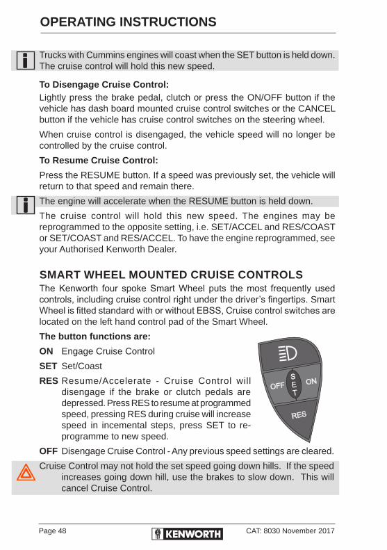
Page 48 CAT: 8030 November 2017
OPERATING INSTRUCTIONS
Trucks with Cummins engines will coast when the SET button is held down. The cruise control will hold this new speed.
To Disengage Cruise Control:Lightly press the brake pedal, clutch or press the ON/OFF button if the vehicle has dash board mounted cruise control switches or the CANCEL button if the vehicle has cruise control switches on the steering wheel.
When cruise control is disengaged, the vehicle speed will no longer be controlled by the cruise control.
To Resume Cruise Control:
Press the RESUME button. If a speed was previously set, the vehicle will return to that speed and remain there.
The engine will accelerate when the RESUME button is held down.
The cruise control will hold this new speed. The engines may be reprogrammed to the opposite setting, i.e. SET/ACCEL and RES/COAST or SET/COAST and RES/ACCEL. To have the engine reprogrammed, see your Authorised Kenworth Dealer.
SMART WHEEL MOUNTED CRUISE CONTROLSThe Kenworth four spoke Smart Wheel puts the most frequently used controls, including cruise control right under the driver’s fingertips. Smart Wheel is fitted standard with or without EBSS, Cruise control switches are located on the left hand control pad of the Smart Wheel.
The button functions are:
ON Engage Cruise Control
SET Set/Coast
RES Resume/Accelerate - Cruise Control will disengage if the brake or clutch pedals are depressed. Press RES to resume at programmed speed, pressing RES during cruise will increase speed in incemental steps, press SET to re-programme to new speed.
OFF Disengage Cruise Control - Any previous speed settings are cleared.
Cruise Control may not hold the set speed going down hills. If the speed increases going down hill, use the brakes to slow down. This will cancel Cruise Control.

CAT: 8030 November 2017 Page 49
OPERATING INSTRUCTIONS
CUMMINS ENGINE BRAKE (WHERE FITTED)The master switch located on the steering wheel turns the system ON or OFF. This switch also performs the progressive braking function which controls the amount of retarding.
Engine Brake Light Display
If your vehicle has the three-level system, you can select low (1), medium (2), or high (3) retarding. If it has the two-level system, you can select FULL or HALF.
Two-level system has either three (low) or all six (high) cylinder operations, while the three-level system operates two (low), four (med) or all six (high) cylinders.
SMART WHEEL MOUNTED ENGINE BRAKE CONTROLSThe Kenworth four spoke Smart Wheel places the most frequently used controls; including, engine brake right under the driver’s fingertips.For more information on when and how to use the engine brake in your vehicle, see the Electronic Customised Maintenance Manual, Section 11, CAT:8432.

Page 50 CAT: 8030 November 2017
OPERATING INSTRUCTIONS
TURBO TIMER (OPTIONAL)A turbocharger is a combination turbine and compressor joined by a common shaft. Super-hot exhaust gases (exceeding 700°C) from the engine pass through the turbocharger causing it to revolve at very high speeds (up to 100,000 rpm).
At normal engine shutdown, the turbo temperature is high and the lubrication to the bearings stops instantly. Unless precautions are taken, the turbo can be damaged by heat distortion and oil varnishing on the shaft and bearings of the turbo. This can cause premature failure of the turbo.
Turbo Timer Control with Display Lights
The most common Engine Idle Timer fitted to Kenworth trucks has the option to select 0.5, 1, 2, 3, 4 or 5 minutes before shutdown after the truck has been safely parked and the key removed. There is also provision to shut down the engine instantly if required.Engine manufacturers recommend engines be idled for a few minutes to allow the turbocharger to cool down and normalise while maintaining a flow of engine oil to its bearings. If followed at every engine shutdown, this routine will extend turbo life and significantly reduce the likelihood of premature turbo failure.
Locking in an Idle PeriodA preferred idle period may be locked in place, preventing the operator from changing this time selection.
TO LOCK IN:Turn ignition ON
Select the preferred idle period using the MIN. button.
Press and hold the STOP button until all 6 LED’s flash briefly (after approximately 10 seconds).
Turn ignition OFF
This default idle period will remain even if the vehicle battery is disconnected.
TO UNLOCK:Turn ignition ON
Press and hold the MIN. button until all 6 LED’s flash briefly (after approximately 10 seconds).
Turn ignition OFF
The idle period is now released.
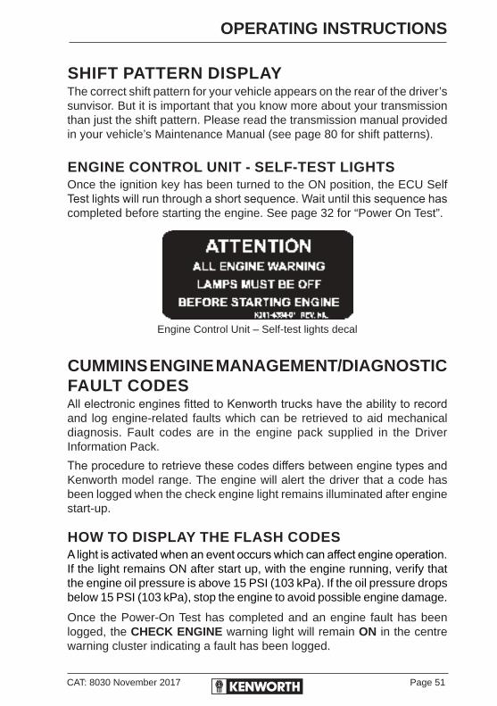
CAT: 8030 November 2017 Page 51
OPERATING INSTRUCTIONS
SHIFT PATTERN DISPLAYThe correct shift pattern for your vehicle appears on the rear of the driver’s sunvisor. But it is important that you know more about your transmission than just the shift pattern. Please read the transmission manual provided in your vehicle’s Maintenance Manual (see page 80 for shift patterns).
ENGINE CONTROL UNIT - SELF-TEST LIGHTSOnce the ignition key has been turned to the ON position, the ECU Self Test lights will run through a short sequence. Wait until this sequence has completed before starting the engine. See page 32 for “Power On Test”.
Engine Control Unit – Self-test lights decal
CUMMINS ENGINE MANAGEMENT/DIAGNOSTIC FAULT CODESAll electronic engines fitted to Kenworth trucks have the ability to record and log engine-related faults which can be retrieved to aid mechanical diagnosis. Fault codes are in the engine pack supplied in the Driver Information Pack.
The procedure to retrieve these codes differs between engine types and Kenworth model range. The engine will alert the driver that a code has been logged when the check engine light remains illuminated after engine start-up.
HOW TO DISPLAY THE FLASH CODESA light is activated when an event occurs which can affect engine operation. If the light remains ON after start up, with the engine running, verify that the engine oil pressure is above 15 PSI (103 kPa). If the oil pressure drops below 15 PSI (103 kPa), stop the engine to avoid possible engine damage.
Once the Power-On Test has completed and an engine fault has been logged, the CHECK ENGINE warning light will remain ON in the centre warning cluster indicating a fault has been logged.
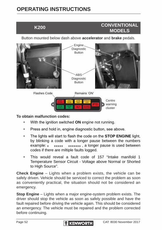
Page 52 CAT: 8030 November 2017
OPERATING INSTRUCTIONS
Button mounted below dash above accelerator and brake pedals.
Flashes Code Remains ‘ON’
To obtain malfunction codes:
• With the ignition switched ON engine not running.
• Press and hold in, engine diagnostic button, see above.
• The lights will start to flash the code on the STOP ENGINE light, by blinking a code with a longer pause between the numbers example: , a longer pause is used between codes if there are miltiple faults logged.
• This would reveal a fault code of 157 “Intake manifold 1 Temperature Sensor Circuit - Voltage above Normal or Shorted to High Source”.
Check Engine – Lights when a problem exists, the vehicle can be safely driven. Vehicle should be serviced to correct the problem as soon as conveniently practical, the situation should not be considered an emergency.
Stop Engine – Lights when a major engine-system problem exists. The driver should stop the vehicle as soon as safely possible and have the fault repaired before driving the vehicle again. This should be considered an emergency. The vehicle must be repaired and the problem corrected before continuing.
K200 CONVENTIONALMODELS
STOP
ENGINE
INTERAXLE
LOCK
CHECK
ENGINE
ENGINE
FAN
GEARBOX
PRESSURE
AFTER
TREAT
ALTCRUISE
ENABLE
PTO
EngineDiagnostic
Button
ABSDiagnostic
Button
Centrewarningcluster
* ***** *******

CAT: 8030 November 2017 Page 53
OPERATING INSTRUCTIONS
HEATING AND AIRCONDITIONINGThe cab heater and A/C controls are located together on the dash or overhead console, depending on the model. In addition, the sleeper compartment may contain a slave heater/airconditioning system with its controls located on the driver’s side sleeper cabinet.
If a refrigerant leak develops in the presence of excessive heat or an open flame, hazardous gases can be generated. These gases may cause unconsciousness or death. If you become aware of a refrigerant leak on your vehicle, have your system serviced immediately and observe the following precautions:
• Stay away from the hot engine until the exhaust manifold has cooled.
• Do not permit any open flame in the area. Even a match or a cigarette lighter may generate a hazardous quantity of poisonous gas.
• Do not smoke in the area. Inhaling gaseous refrigerant through a cigarette may cause violent illness.
To allow for proper operation of the vehicle ventilation system, keep the inlet grille near the rain tray on most conventional models and the side panel on C510 & T659, or on the front cab panel on K200's, clear of leaves and other obstructions at all times.
Keep the engine exhaust system and the vehicle’s cab/sleeper ventilation system properly maintained. It is recommended that the vehicle’s exhaust and cab/sleeper systems be inspected:
• By a competent technician every 10,000 km.
• Whenever a change is noticed in the sound of the exhaust system.
• Whenever the exhaust system, underbody, cab or sleeper is damaged.
IMPORTANT:
When idling for short periods of time:
• Set the heating or cooling system to Heat or A/C.
• Set the fan to Medium or High speed.
• Set the controls to Recirc.If other vehicles are parked idling next to you, move your vehicle or do not stay in your vehicle for prolonged periods of time.

Page 54 CAT: 8030 November 2017
OPERATING INSTRUCTIONS
CAB HEATER/AIRCONDITIONERTo get the most efficient performance from your heater/airconditioner system, keep the following in mind:
1. Turn airconditioner controls OFF when cooling is not required, except when de-misting the windscreen.
2. With sleeper compartment auxiliary units, cab controls must be ON for the sleeper controls to function. Both units must be set for the same function i.e. heating or cooling.
3. When the airconditioner is not in regular use, operate it for 10 minutes each week to lubricate the seals.
Controls can be set in various positions and, in combination with air controls, and output, the circulation can be regulated to suit the occupants.
The proper sequence for airconditioner operation is:1. Be sure all heater/airconditioning controls are OFF
2. Start the engine, then set airconditioner maximum cooling
a. Set heat setting to COLD on controller.
b. Switch to A/C switch on controller.
c. Turn fan speed to HIGH.
d. Set fresh air/re-circulating switch to preferred setting.
In very humid conditions, it may be better to begin cab cool down on recirculation.
In very hot conditions, set to fresh air, as the cabin temperature will be hotter than ambient, due to cabin heat soak. Once cooled down after 5-10 minutes, close the windows and switch to RECIRC, then alternate between FRESH & RECIRC as desired.If left on RECIRC for long periods, the air will lose moisture and feel dry. If this concerns the occupants, the intake should be switched back to FRESH.
3. Close windows, especially in humid conditions, leaving one slightly opened to allow hot air to vent.

CAT: 8030 November 2017 Page 55
OPERATING INSTRUCTIONS
4. Idle the engine between 1000 and 1500 rpm and turn fan switch(es) on high, if the truck is stationary.
5. After cab temperature cools suitably, adjust blower speed and controls to sustain desired condition.
6 Periodically return to fresh air to ensure clean air is ventilated.
7. Adjusted warm air from the heater can be mixed with cooling air when dry air is needed to defog the windshield.
A/C on recirculation should be the fastest way to demist the windscreen.
In an extremely hot and humid climate, the evaporator may ice over and reduce cooling efficiency if the airconditioner is operated at maximum cooling. If extreme icing occurs, it may be necessary to temporarily turn off the air-conditioner.Water condensing on the evaporator can be trapped by the air flow from the fan or ram air effect. This may reduce the A/C efficiency. In some conditions, it may be necessary to periodically turn the A/C fan off and switch to RECIRC to allow water to drain away.

Page 56 CAT: 8030 November 2017
OPERATING INSTRUCTIONS
1 2 3 4 5 6 7 8 9 10 11 12 13*
14 15 16
Legend to A/C Controller on previous page
1 Face Only 10 Fan LOW
2 Face & Feet 11 Fan MED
3 Feet Only 12 Fan HIGH
4 Feet & Screen 13 Fan BOOST
5 Screen Only 14 Airconditioner ON/OFF Switch NOTE: When A/C Fan on LOW Automatic
6 Heater COLD
7 Heater MED
8 Heater HOT 15 Fresh Air
9 Fan OFF 16 Recirculated Air
CAB HEATER/AIRCONDITIONER CONTROLS

CAT: 8030 November 2017 Page 57
OPERATING INSTRUCTIONS
SLEEPER AIRCONDITIONER (A/C) CONTROLS (IF FITTED)
Heater / Airconditioner Mode
2
1 3Fan Control
Temperature Control
Sleeper A/C: The Cab Heater and A/C Controls must have the Air Direction Lever on A/C, and a fan setting selected for the sleeper A/C unit to work.
Fan Control (1): Allows you to select different blower speeds.Heat & A/C Control Mode (2): Allows you to select Heat or A/C.
Heat Mode: The fan cycles on/off to regulate temperature based on the Temperature Control (3) setting.
A/C Mode: A refrigerant solenoid valve cycles open/closed to regulate the temperature, based on the Temperature Control (3) setting.

Page 58 CAT: 8030 November 2017
OPERATING INSTRUCTIONS
CAB STORAGE
To open the overhead storage compartments in K200 and sleeper compartments, push/pull the release catch until it releases. To close, close the compartment door until it latches.
INTERIOR COMPARTMENTSThere are a variety of interior storage compartments to store your personal supplies or small tools:
• Glove box.
• Overhead storage compartments.
• Sleeper storage compartments.
• Centre console.
• Map pocket/records holder, on front of rider’s seat base (conventional models only).
• Records holder, between seat and engine tunnel (K200).Do not carry loose objects in your cab. It can be dangerous. In a sudden stop, or even going over a bump in the road, they could fly through the air and strike you or your passenger. Carry any heavy objects such as luggage in the exterior storage compartment and close it securely.
TOOLBOXESIT conventional models and cab with sleeper have additional storage or toolboxes, overloading these with heavy objects such as dogs and chains etc.... will overload the cab suspension.
It is recommended that maximum cargo weight in K200 with 2.8m cab does not exceed 60kg per toolbox, including any aftermarket additions or fitments.

CAT: 8030 November 2017 Page 59
OPERATING INSTRUCTIONS
SEATSThis section covers the operation and safe use of your Kenworth seats. For further information on features and adjustment of the seat, see the manufacturer’s Service and Operation information supplied with the vehicle.
SEAT ADJUSTMENTDo not adjust the driver’s seat while the vehicle is moving. The seat could move unexpectedly and can cause the driver to lose control of the vehicle. After adjusting the seat, and before driving off, always check to ensure the seat is firmly latched in position.
Standard Driver’s SeatThe standard driver’s seat can be adjusted forward and backward as well as up and down. The seat back angle can also be adjusted. These three movements are each controlled by levers located either beneath, or at the sides of the seat.
Driver’s Seat with Air SuspensionBefore driving or riding in the vehicle, ensure there is adequate head clearance at maximum upward seat travel. You could seriously injure your head or neck by bumping into the cab roof if clearance is not adequate.
Reclining SeatsReclining seats are easy to use if you follow these steps:
1. Make sure the sleeper curtain is tied back.
2. Raise the seat all the way up so the seat will tilt back and completely clear objects behind you.
3. Do not drive or ride with your seat back in the reclined position. You could be injured by sliding under the seatbelts in a collision.
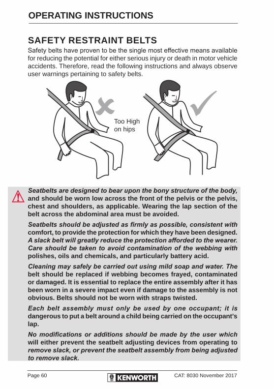
Page 60 CAT: 8030 November 2017
OPERATING INSTRUCTIONS
SAFETY RESTRAINT BELTSSafety belts have proven to be the single most effective means available for reducing the potential for either serious injury or death in motor vehicle accidents. Therefore, read the following instructions and always observe user warnings pertaining to safety belts.
Seatbelts are designed to bear upon the bony structure of the body, and should be worn low across the front of the pelvis or the pelvis, chest and shoulders, as applicable. Wearing the lap section of the belt across the abdominal area must be avoided.
Seatbelts should be adjusted as firmly as possible, consistent with comfort, to provide the protection for which they have been designed. A slack belt will greatly reduce the protection afforded to the wearer. Care should be taken to avoid contamination of the webbing with polishes, oils and chemicals, and particularly battery acid.
Cleaning may safely be carried out using mild soap and water. The belt should be replaced if webbing becomes frayed, contaminated or damaged. It is essential to replace the entire assembly after it has been worn in a severe impact even if damage to the assembly is not obvious. Belts should not be worn with straps twisted.
Each belt assembly must only be used by one occupant; it is dangerous to put a belt around a child being carried on the occupant’s lap.
No modifications or additions should be made by the user which will either prevent the seatbelt adjusting devices from operating to remove slack, or prevent the seatbelt assembly from being adjusted to remove slack.
Too Highon hips

CAT: 8030 November 2017 Page 61
OPERATING INSTRUCTIONS
LAP & SHOULDER BELTThe combination lap-shoulder belt is equipped with a locking mechanism. The system adjusts automatically to a person’s size and movements as long as the pull on the belt is slow. Hard braking or a collision locks the belt. The belt will also lock when vehicle is going up or down a steep hill or in a sharp curve.
Make sure all seatbelts are correctly adjusted before moving the vehicle. Adjustment is made by sliding the adjusting buckle either up or down the seatbelt until the belt is comfortable. Take care not to over tighten the belt by removing all of the slack.
Safety Restraint Tips• Anyone riding in your vehicle should wear a correctly adjusted
seatbelt. A responsible operator sees to it that everyone in the vehicle rides safely and that means with a seatbelt.
• Do not wear a belt over rigid or breakable objects in or on your clothing, (for example eye glasses, pens, keys) as these may cause injury in an accident.
• Several layers of heavy clothing may interfere with proper positioning of belts and reduce the overall effectiveness of the system.
• Keep belt buckles free of any obstruction that may prevent secure locking.
• Cab or sleeper belts which have been damaged or worn because of cuts, tears, normal wear or excessive stretch forces from crashes must be replaced. They may not protect you if you have an accident.
• If belts show damage to any part of their assembly, such as webbing, bindings, buckles or retractors, they must be replaced.
• Do not allow safety belts to become damaged by getting caught in the door or seat hardware, or by rubbing against sharp objects.
• The belts must be kept clean or the retractors may not work properly.
• Never bleach or dye seatbelts; chemicals can weaken them. Do, however, keep them clean by following the directions on the care label on the belts. Let them dry completely before allowing them to retract.

Page 62 CAT: 8030 November 2017
OPERATING INSTRUCTIONS
• Make sure the belt of the unoccupied passenger seat is fully wound up on its retractor, so the belt tongue is in its stowed position. This reduces the possibility of the tongue becoming a striking object in a sudden stop.
• Do not modify or disassemble the seatbelts in your vehicle. They will not be available to keep you and your passengers safe.
• If any seatbelt is not working properly, see your authorised Kenworth service centre for repair or replacement.
SLEEPER - BUNKS AND RESTRAINTSFor Kenworth cabs equipped with a sleeper, be sure to use the fitted restraint devices. Your vehicle may have belts and/or a net restraint system which are over the bunk or cover the opening.
Be sure to stow away all loose belongings before you move your vehicle. Do not store objects on the bunks. They could cause serious damage or injury in an accident.

CAT: 8030 November 2017 Page 63
OPERATING INSTRUCTIONS
OPERATING THE ENGINE
NORMAL STARTING PROCEDURE1. Ensure the parking brake is set ON and the transmission shift
lever is in NEUTRAL. For automatic transmissions that have park position, place the shift lever in park.
2. With the accelerator pedal in the idle position, turn the ignition key to the START position.
3. Release the key after 10 seconds if the engine does not start. Then wait for 10 seconds and try again.
If the engine is running, do not increase engine speed (rpm) or operate the vehicle until the low oil pressure warning light turns OFF.
As soon as the engine starts, watch the oil pressure gauge. Refer to your engine manufacturer’s glovebox handbook for engine idle speed oil pressure. If oil pressure does not rise within a few seconds, stop the engine. Locate and correct the trouble before starting the engine again.
Engaging the starter motor for more than 30 seconds in any 5 minute period may cause it to overheat and can damage the starter motor.
If the starter is engaged continuously fo 30 seconds, you MUST wait 35 minutes before trying to start the engine again to allow the starter motor to cool down.
Watch the primary and secondary air pressure gauges. They should both register 689 kPa before you release the park brake and move the vehicle. Also check the alarm system for any type of faults and correct them before moving the vehicle.
Unnecessary stress and possible brake malfunction could occur if the vehicle is forced to move before the air system reaches 689 kPa.
TURBOCHARGED ENGINES: Do not idle or accelerate the engine over 1000 rpm until normal engine oil pressure registers on gauge.
If the engine has not been started for over 25 days, or the outside temperature is extremely low, or oil filter has been changed, squirt about 120 ml of clean, specified engine oil into the turbocharger oil-inlet port with an oil can. This will keep turbocharger bearings lubricated until engine oil pressure builds up to normal.
Page 64 CAT: 8030 November 2017
OPERATING INSTRUCTIONS
ENGINE WARM-UPThe purpose of engine warm-up is to allow an oil film to be established between pistons, shafts and bearings while your engine gradually reaches operating temperature.
After the engine starts, the electronics will check the coolant temperature and other engine temperature indicators. If needed, the ECM will take necessary action(s) to warm the engine up. This is called cold mode. Depending on the engine type, this may include changing the idle speed of the engine. It may also reduce the amount of power available.
The engine should be brought up to operating temperature gradually while oil films are re-established between pistons and liners, shafts and bearings.
The engine must have adequate oil pressure within 15 seconds after starting. If the warning light indicating low oil pressure has not gone out, the ECM low oil pressure warning activates; or if there is no oil pressure indicated on a gauge within 15 seconds, shut off the engine immediately to avoid engine damage. Confirm the correct oil level in the engine sump.Once the engine has warmed sufficiently to exit cold mode, the engine should be operated at low rpm and low load until normal operating temperature is reached. Operating the engine in this way will warm it faster than if the engine is operated at high rpm and low load.
Slow oil flow to the turbocharger reduces oil available for bearings. Watch engine oil temperature or pressure gauges for a warming trend before increasing engine idle rpm.
Check alternator output. The voltmeter must read between 13.8 and 14.2 volts.
Warm-Up ProcedureAfter you start the engine, idle the engine at approximately 600 rpm while you check the following vital engine systems:
• Oil pressure.
• Air pressure.
• Alternator output.Before placing engine under load, continue warm-up with the engine at 900 to 1,000 rpm for 3 to 5 minutes.
CAT: 8030 November 2017 Page 65
OPERATING INSTRUCTIONS
When a cold engine is started, increase the engine speed (rpm) slowly to be sure adequate lubrication is available to the bearings and to allow the oil pressure to stabilise. In extremely cold temperatures, you may have to increase idle speed.
In colder climates where the temperatures are often below freezing, sufficient warm-up for turbocharged engines is especially important. Chilled external oil lines leading to the turbocharger will slow the oil flow until the oil warms, reducing oil available for the bearings. Watch the engine oil temperature or pressure gauge for a warming trend before increasing engine idle speed (rpm).
Continue the engine warm-up until the coolant temperature reaches at least 54°C. At this temperature, you can use partial throttle. Wait until the coolant temperature is at least 71°C before operating at full throttle. See Transmission Warm-Up, page 74.
Exhaust fumes from the engine contain carbon monoxide, a colourless and odourless gas. Do not breath the engine exhaust gas. A poorly maintained, damaged or corroded exhaust system can allow carbon monoxide to enter the cab or sleeper.
Entry of carbon monoxide into the cab is also possible from other vehicles nearby. Failure to properly maintain your vehicle could cause carbon monoxide to enter the cab/sleeper and cause serious illness.
Never idle your vehicle for prolonged periods of time if you sense that exhaust fumes are entering the cab or sleeper. Investigate the cause of the fumes and correct the problem as soon as possible. If the vehicle must be driven under these conditions, drive only with the windows open. Failure to repair the source of the exhaust fumes may lead to personal harm.
Keep the engine exhaust system and the vehicle’s cab/sleeper ventilation system properly maintained. It is recommended that the vehicle’s exhaust system and cab/sleeper be inspected:
• By a competent technician every 10,000 km.
• Whenever a change is noticed in the sound of the exhaust system.
• Whenever the exhaust system, underbody, cab or sleeper is damaged.
Page 66 CAT: 8030 November 2017
OPERATING INSTRUCTIONS
Before Driving Away1. Check ALL operating temperatures and pressures are within correct
range.
2. Check operation of windshield washers and wipers.
3. Check horn (electric and air) operation.
4. Check position of the inter-axle differential control.
5. Turn Emergency flashers OFF.
6. Check air suspension is inflated.
7. Load-test trailer hitch for security.
8. Check service brake operation and air pressure gauges.
Engine Oil Temperature GaugeThe Engine Oil Temperature gauge indicates engine oil temperature. Do not exceed the maximum engine oil temperature recommended by the engine manufacturer. See the Engine Operation and Maintenance Manual for details.
WINTERFRONTSWinterfronts or other air-flow restriction devices are sometimes mounted in front of radiators. Kenworth discourages their use with air-to-air aftercooler or intercooled engines. The use of a winterfront can result in excessive engine coolant, oil, and charge air (intake) temperatures, which can lead to overheating and possible engine damage.

CAT: 8030 November 2017 Page 67
OPERATING INSTRUCTIONS
IDLING THE ENGINEDo not idle for extended periods of time. Excessive idle time can cause poor engine performance and waste fuel.
Internal combustion engines must not operate at low idle speed for extended periods of time. This operating condition may lead to poor engine performance. The idle shutdown feature, available on most Cummins engines, can be programmed to shut the engine down after a period of low idle speed operation with no driver activity.
A flashing warning lamp will inform the driver of an impending shutdown. If an engine must idle for an extended period of time, it should be done at fast idle (1000 rpm or greater).
The Power Take-Off (PTO) feature, available on most Cummins engines, can be programmed to adjust engine speed with the use of OEM switches to pre-programmed set points.
After starting the engine idle the engine 3 to 5 minutes before operating with a load.
After starting a cold engine, increase the engine speed (rpm) slowly to provide adequate lubrication to the bearings and to allow the oil pressure to stabilise.
Do not operate engine at low idle for long periods with engine coolant temperature below the minimum specification in Coolant Recommendations and Specifications.
Low coolant temperature can result in:• Fuel dilution of the lubricating oil.
• Carbon build-up in the cylinder.
• Cylinder head valve sticking.
• Reduced performance.
Engine Fan ControlIf your vehicle is equipped with this option, the engine fan can be turned ON using a switch that is mounted on the dash. This lets you set the fan to manual or automatic operation.
With the ignition key turned ON and the fan switch in the MANUAL position, the engine fan will be ON regardless of engine temperature.

Page 68 CAT: 8030 November 2017
OPERATING INSTRUCTIONS
ENGINE AFTERTREATMENT SYSTEMS (EAS)In order to meet ADR 80/03 engine emission requirements, vehicles must have an Exhaust Aftertreatment System (EAS) which will include either Selective Catalytic Reduction for ISLe5, ISMe5 and X15e5 engines, or a Diesel Particulate Filter foe ISX EGR and Signature EGR engines. THese are two different systems and your vehicle may have either one installed.
SELECTIVE CATALYTIC REDUCTION (SCR)
ISLe5, ISMe5 & X15e5 ENGINESIf your truck is equiped with a Selective Catalytic Reduction (SCR) it uses Diesel Exhaust Fluid (AdBlue) to reduce emissions from diesel engines. DEF is injected into the exhaust gas upstream of the catalyst. DEF is consumable and needs to be replenished.
Close to Empty (approx 12% remaining) - AdBlue warning light will illuminateon the AdBlue Gauge
ADBLUE LOW LEVEL WARNING AND INDUCEMENTThe low DEF warning light will illuminate when the DEF level is at 12% to warn the operator to refill the SCR system, at 6% the light will start to blink and the engine will derate. The derate would take effect when the vehicle speed goes to 0 km/h or when the engine goes to idle.
For trucks with SCR and battery isolation switch: the battery isolation switch should not be switched off immediately, driver must wait 40 seconds after turning off the ignition. Shutting off the battery isolation switch whilst the engine is running or before the 40 second period is completed, will cause serious damage to the engine diagnostics.
If the DEF indicator light turns on, check the DEF level and refill if necessary. Failure to refill may cause the engine to derate and limit vehicle speed.
Warning light12%
6%

CAT: 8030 November 2017 Page 69
OPERATING INSTRUCTIONS
EAS SYSTEM TAMPERINGIf the engine system detects failures that may be the result of tampering with the EAS system, the Check Engine light will come on, the engine will derate, and if fitted the warning lamp will be on.
DIESEL EXHAUST FLUID - AdBlue QUANTITYIf the engine detects that DEF quantity is below acceptable levels the DEF warning light will flash, the Check Engine light will come on and the engine will be derated.
Levels given are for example only. Actual levels depend on specific vehicle configuration. SCR System Tampering: If the engine system detects failures that may be the result of tampering with the SCR system, the Check Engine light will come on, the engine will derate, and if equipped the MIL (Malfunction Indicator Lamp) will be on. DEF Quantity: If the engine detects that DEF quantity is below acceptable levels (12%) the DEF warning light will flash, when the level is below 6% the Check Engine light will come on, and the engine will be derated.
Stop Engine Check Engine After Treat(ment)Warning Light Warning Lamp Warning Light
DEF Warning Lights in Centre Cluster
‘ENGINE DERATE’ MEANS; ENGINE POWER LIMITINGDerate will only be activated at vehicle standstill or at engine idle if the vehicle speed sensor has failed.
When the above conditions to activate derate are no longer applicable, the derate is de-activated immediately.
Derate will be de-activated as soon as the OBD (On Board Diagnostics) monitor of the specific fault has completed and passed.
STOP
ENGINE
INTERAXLE
LOCK
CHECK
ENGINE
ENGINE
FAN
GEARBOX
PRESSURE
AFTER
TREAT
ALTCRUISE
ENABLE
PTO
Page 70 CAT: 8030 November 2017
OPERATING INSTRUCTIONS
DIESEL EXHAUST FLUID - AdBlueDiesel Exhaust Fluid, AdBlue is also known as: AUS32 (Aqueous Urea Solution 32), NoNOx, NOx Reduction Agent or Catalyst Solution. Diesel Exhaust Fluid must meet ISO22241-1. To avoid malfunction and damage of the system, it is important to strictly observe the following precautions.
• It is recommended to fill the AdBlue tank directly with AdBlue supplied by PACCAR Parts or any other supplier (always from the original packaging), using official AdBlue filling equipment.
• Always top up the system with 100% clean AdBlue according to DIN 70070. Never use contaminated AdBlue or contaminated canisters or funnels to top up the AdBlue tank.
• Avoid diesel mixing with AdBlue in the AdBlue tank: always use 100% clean canisters and funnels that have not been used for any other liquids, such as coolant, oil, diesel or petrol.
Safety• Avoid physical contact with AdBlue.
• In event of skin contact, rinse with water.
• In event of contact with eyes, rinse with water for 15 min and consult a doctor.
• If swallowed, drink water, don’t induce vomiting.
• In the event of inhalation get fresh air, rest and consult a doctor.
General Warning• The DPF should not be submersed (even partially) in water. In
regions where vehicles are likely to negotiate forded water, the DPF need to be located high so that no part of it is submersed at any time during vehicle operation.
• Keep system and vehicle clean to avoid crystallisation of AdBlue, potential corrosion, staining and discoloration by washing the immediate area with clean fresh water, ensure AdBlue is not allowed to crystalise around electrical wiring harness, particularly around connector blocks.
• It is not allowable to open the dosing module EAS. Therefore internal components cannot be changed.

CAT: 8030 November 2017 Page 71
OPERATING INSTRUCTIONS
• Replace the AdBlue filler cap as soon as filling of the AdBlue tank is completed, do not allow foreign matter to enter the AdBlue tank.
ADBLUE FILLINGWhen filling the AdBlue tank, the filler neck is welded at a specific location to enable part of it to be inserted within the tank, this physically prevents the tank being filled over 90% due to the AdBlue reaching the bottom of the neck and causing a “head” of air which becomes trapped in the top 10% of the tank. This design allows the automatic fuel shut off at the pump to work.Do not attempt to overfill the tank above 90% of its capacity. Ninety percent is to the edge of the filler neck so that air gap is not visible, as this provides room for expansion resulting from temperature extremes.
Ensure that the “AdBlue” lettering and symbol are in the horizontal position when the filler cap is fully screwed on. The lettering can be either the right way up or upside down (180°), to ensure correct sealing of the AdBlue tank.
DIESEL PARTICULATE FILTER (DPF)
ISXe5/EGR & SIGNATUREe5/EGR ENGINESIf your vehicle has a DPF it will be equipped with the following
EXHAUST AFTERTREATMENT SYSTEM (EAS) WARN-ING LIGHTSEAS specific warning lights and indicator symbols are located on the DPF Warning Light Module.
DPF STATUS
Exhaust Aftertreatment System Warning Lights
Diesel Particulate Filter (DPF) Warning Light
Symbol
High Exhaust System Temperature (HEST) Warning Light Symbol

Page 72 CAT: 8030 November 2017
OPERATING INSTRUCTIONS
DPF REGENERATIONCarefully read the the instructions in Section 14, Exhaust System CAT: 8349 of your Electronic Customised Maintenance Manual in your Driver Information Pack or contact your nearest authorised PACCAR dealer for assistance.
FUNCTIONALITYThe EAS will regenerate the DPF by using hot exhaust gases normally generated by the engine. This typically occurs during highway operation, and is referred to as a “Passive” Regeneration, and is transparent to the operation of the vehicle.
Occasionally, the exhaust gases are not hot enough for passive regeneration. When this occurs, the EAS will regenerate the DPF by increasing the exhaust temperature. This is referred to as an “Automatic” Regeneration and is also transparent to vehicle operation. An Automatic Regeneration event typically lasts 30 minutes. During and shortly after the event, the exhaust gases from the DPF may reach temperatures in excess of 650°C (1200°F). See the information in the Electronic Customised Maintenance Manual on probable causes and recommended actions related to the warning lights and indicator symbols of the EAS.
The EAS may not be able to regenerate the DPF when the vehicle is driven at extended low speeds or with frequent starts and stops. In such cases, warning lights and indicator symbols will alert the operator to take action.The operator should be aware of whether the lights are on alone or in combination with others.
CONTROLLING THE REGENERATION PROCESSYour vehicle is equipped with a three-position Regeneration Switch, mounted on the dash. With a three-position Regeneration Switch, the driver can initiate a parked regeneration when certain operating conditions are suitable for regeneration. However, you will NOT be able to stop a regeneration if the EAS has initiated one automatically. Refer to CAT: 8349 of your electronic version of the Electronic Customised Maintenance Manual.
With the three-position Regeneration Switch, the driver can control the regeneration by overriding the EAS when certain operating conditions are not suitable for regeneration. Refer to CAT: 8349 of your electronic version of the Electronic Customised Maintenance Manual.
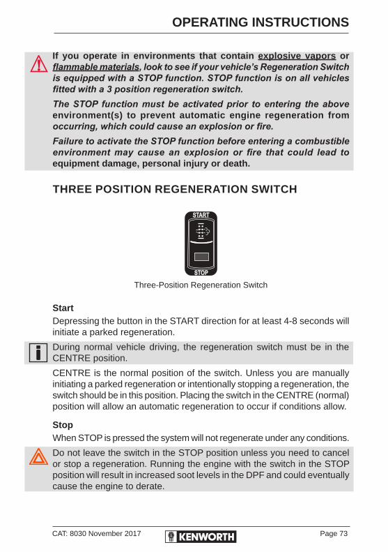
CAT: 8030 November 2017 Page 73
OPERATING INSTRUCTIONS
If you operate in environments that contain explosive vapors or flammable materials, look to see if your vehicle’s Regeneration Switch is equipped with a STOP function. STOP function is on all vehicles fitted with a 3 position regeneration switch.The STOP function must be activated prior to entering the above environment(s) to prevent automatic engine regeneration from occurring, which could cause an explosion or fire.Failure to activate the STOP function before entering a combustible environment may cause an explosion or fire that could lead to equipment damage, personal injury or death.
THREE POSITION REGENERATION SWITCH
START
STOP
Three-Position Regeneration Switch
StartDepressing the button in the START direction for at least 4-8 seconds will initiate a parked regeneration.
During normal vehicle driving, the regeneration switch must be in the CENTRE position.
CENTRE is the normal position of the switch. Unless you are manually initiating a parked regeneration or intentionally stopping a regeneration, the switch should be in this position. Placing the switch in the CENTRE (normal) position will allow an automatic regeneration to occur if conditions allow.
StopWhen STOP is pressed the system will not regenerate under any conditions.
Do not leave the switch in the STOP position unless you need to cancel or stop a regeneration. Running the engine with the switch in the STOP position will result in increased soot levels in the DPF and could eventually cause the engine to derate.

Page 74 CAT: 8030 November 2017
OPERATING INSTRUCTIONS
OPERATING THE TRANSMISSIONBecause each Kenworth is custom-equipped, the specific operating procedures for your particular transmission are not included in this handbook. Therefore, you should read the general guidelines and instructions that follow, and read the specific instructions contained in the transmission manufacturer’s Driver/Operator’s Instruction Manual.
TRANSMISSION OIL PRESSUREA transmission oil pressure warning light is located in the centre of the dash panel (except T359 with ISLe5 engine). This illuminates when the ignition is switched on with the engine stopped, or when the oil pressure is low during normal driving. If the transmission oil pressure warning light comes on while you are driving, pull the vehicle to the side of the road safely and check your transmission oil level.
K200 OnlyDo not operate the vehicle if you notice a gradual or sudden increase in cable shift effort or a decrease in the usable travel. This can cause incorrect engagement and you could slip out of gear. Take the vehicle to the nearest Authorised Kenworth Dealer for repair.
Transmission shift cables are designed to be contaminant resistant, not contaminant proof. Protect cables from contaminants, chemicals and physical abuse, which may damage the control cables.
Shift control cables are lubricated for life and are non-repairable. If you detect moisture or a broken seal, or if the cable has frozen, the shift cable must be replaced. Do not apply heat to thaw the cables.
Transmission Warm-UpTo warm up the transmission lubricating oil during engine warm-up, check that the transmission is in NEUTRAL and release the clutch pedal. This will allow the transmission counter-shaft to turn and agitate the oil, thereby warming it. This practice is particularly desirable in cold weather operation when sluggish shifting may be experienced.
Operating Manual TransmissionsYou will find a shift pattern diagram in the cab. Check to be sure that you know the correct sequence for your particular transmission. A decal with the shift pattern and operating instructions is normally located on the sun visor.

CAT: 8030 November 2017 Page 75
OPERATING INSTRUCTIONS
PUTTING THE VEHICLE IN MOTIONAfter making sure the vehicle’s oil and air pressure are correct and all other parts and systems are in proper working condition:
1. Fully depress the clutch pedal (for manual transmission) until the clutch brake makes contact. The contact will occur at about 25 mm or less from the floorboard.
• The total stroke of the clutch pedal is approximately 254 mm. The first 38 mm is free travel. Solo clutches have 12-76 mm of free travel. After the free travel comes the release stroke, which is the part that fully releases the clutch. The last 25 mm engages the clutch brake (see page 199).
Always use first gear or a low speed range to start the vehicle in motion. The use of a higher gear or speed range forces undue strain on the engine, clutch and other transmission components, and may cause damage.
2. Evaluate the road surface conditions and terrain your vehicle is on. Select a gear low enough to let your vehicle start forward with the throttle at idle.
3. Push the parking brake valve handle (Yellow) against the dash panel to release the brakes.
4. Release the clutch pedal (manual only), then gradually accelerate to permit smooth starting.
5. Do not allow your vehicle to roll (even a little) in the opposite direction during clutch engagement. If you need to start up on an incline, apply your service brakes before you release the parking brake. Then release your service brakes as you engage the clutch and apply throttle.
If you have a misaligned gear condition in your vehicle’s transmission and cannot start, gradually release the clutch, allowing the drive gear teeth to line up properly. Then the drive gear can roll enough to allowing the teeth to line up properly and complete the shift.
Page 76 CAT: 8030 November 2017
OPERATING INSTRUCTIONS
The best engine performance and maximum economy are obtained if gears are properly selected. This efficiency is achieved by always selecting gears within optimum engine rpm, which is where maximum torque and power are obtained. For further information, see Driving Tips and Techniques, page 122.
For further instructions on operating your transmission, see the transmission manufacturer’s Driver/Operator’s Instruction Manual.
SHIFTING GEARS IN A NEW VEHICLEShift gears carefully in a new vehicle. The transmission may be a little stiff at first. Avoid gear clashing by closely following these procedures:
• When you are operating a new vehicle or one that has been exposed to cold weather, you want the transmission lubricant (fluid) to circulate and coat the contacting surfaces of the gears.
• Metal contacting metal in moving parts may seriously damage your transmission. Do not drive in one gear for long periods of time until the transmission lubricant has had a chance to coat all contacting surfaces.
• Carefully observe the free travel in the clutch for the first few hundred kilometres. As the clutch lining wears and high spots get worn smooth, you will get less free travel.
CLUTCH BRAKE AND TRAVELThe clutch brake is used for stopping transmission gears, allowing you to easily shift into first gear or reverse without grinding gears. Approximately the last 25 mm of clutch pedal travel activates the clutch brake (see page 200).
To apply the clutch brake (while the vehicle is stopped) fully depress the clutch pedal to the floorboard to stop the gears. With the throttle at idle, select first gear, then release the clutch pedal to let the vehicle start forward, until the clutch is fully engaged. See the manufacturer’s Driver/Operator’s Instruction Manual for further details.
If the transmission has a butt-tooth condition and you cannot engage a gear, gradually release the clutch. Then the drive gear can roll enough to allow the teeth to line up properly and complete the shift.

CAT: 8030 November 2017 Page 77
OPERATING INSTRUCTIONS
During Normal DrivingIf you want to shift directly into any gear other than first or reverse, depress the clutch pedal only far enough to release the clutch. Pushing the clutch to the floor applies the clutch brake and will cause gear hang-up.Be careful not to apply the clutch brake while the vehicle is moving. The purpose of the clutch brake is to stop the transmission so you can shift into a starting gear without grinding gears. Applying the clutch brake when the vehicle is moving causes a braking effect on the drivetrain and shortens the service life of the clutch brake.
DOUBLE CLUTCHINGWhether you are up-shifting or down-shifting, it is best to double clutch. Double clutching is easier on the transmission and engine, helping your vehicle match engine speed with driveline speed and achieving clash-free shifts.
To double clutch:1. Push the clutch pedal down to disengage the clutch.
2. Move the gear shift lever to neutral.
3. Release the pedal to engage the clutch. This lets you control the rpm of the mainshaft gears, allowing you to match the rpm of the mainshaft gears to those of the output shaft.
Upshifts: let the engine and gears slow down to the rpm required for the next gear.
Downshifts: press accelerator and increase engine and gear speed to the rpm required in the lower gear.Now quickly press the pedal to disengage the clutch and move the gear shift lever to the next gear speed position.
Release the pedal to engage the clutch.

Page 78 CAT: 8030 November 2017
OPERATING INSTRUCTIONS
CLUTCH OPERATION
STARTINGTo properly put a vehicle into motion, depress the clutch pedal until the clutch brake is contacted. This contact should occur 25 mm or less from the floorboard - excluding carpet. Select a gear low enough to allow the vehicle to start forward with throttle at idle until the clutch is fully engaged.
This procedure is especially important with ceramic or metallic-faced clutches. Do not “feather” or attempt to slip the clutch to start in a higher gear, even if load conditions are light. Any slippage of a ceramic or metal-faced clutch will result in very aggressive engagement and a very jumpy start. Also, do not allow the vehicle to roll at all in the opposite direction during clutch engagement. The service brakes may be used to accomplish a start from a full stop.
Once the vehicle is moving, do not attempt to use the clutch brake. The clutch brake provides a means of stopping the transmission so that the shift into a starting gear may be accomplished with “raking”.
Once the vehicle is in motion, use of the clutch brake will try to stop the vehicle, resulting in very short service life of the clutch brake.
Release Bearing WearWhenever the engine is idling for any period of time, shift transmission to neutral and disengage the clutch to prevent unnecessary wear of the clutch release bearing.
Riding the ClutchDO NOT use the clutch pedal for a foot rest, or drive with your foot resting on the clutch pedal. This allows the clutch to slip, which in turn causes excessive heat, wear and possible damage.
Clutch AdjustmentManual and self-adjusting clutches must be inspected periodically to maintain proper adjustment (see Maintenance Schedule for recommended interval).
Drivers of new vehicles should carefully note free travel clearance during the first few hundred kilometres. As clutch lining wears, free travel decreases. Any high spots on the new clutch will quickly wear smooth, causing free travel to diminish more rapidly than usual.

CAT: 8030 November 2017 Page 79
OPERATING INSTRUCTIONS
Inspect manual clutches according to the manufacturer’s recommendations. Regular maintenance should be followed to maintain correct clutch adjustment. Have your dealer’s service department perform any adjustment necessary.
Clutch Tips• Always use the clutch when making upshifts or downshifts.
• Always select a starting gear that will provide sufficient gear reduction for the load and terrain.
• Never downshift when the vehicle is moving too fast.
• Never slam or jerk the shift lever to complete gear engagement.
• Never coast with the transmission in neutral and the clutch disengaged.
• To provide smooth gear engagements while shifting, use proper coordination between shift lever and clutch.
TRANSMISSION OIL TEMPERATURE GAUGEThe Transmission Oil Temperature Gauge (option) indicates the temperature of the oil in the transmission. Watch this gauge to know when the transmission is overheating: (max 120°). If it is, have it checked by an authorised service representative.

Page 80 CAT: 8030 November 2017
OPERATING INSTRUCTIONS
EATON FULLER TRANSMISSION SHIFT PATTERNS
IN
OUT
RANGE REDUCTIONSELECTOR(LO-LO)
Roadranger
20468
RANGESELECTOR
15 SPEED (RT & RTX)
SPLITTER SELECTOR
43011
94
RANGESELECTOR
13 SPEED (RTO, RTLO & RTOX)Eaton Fuller
Transmissions
5 H
L
H
L
H
L
H
L
MAY BE SHIFTEDIN 5-6-7-8 ONLYDO NOT RANGE SHIFTWITH SPLITTERSELECTOR IN H
PRE-SELECT RANGE SHIFTS
BEFORE
UPSHIFTING
DOWNSHIFTING
DO NOT CHANGE RANGE WHILE MOVING IN REVERSE
(MOVE RANGE SELECTOR MOVING SHIFT LEVER)
START WITH RANGE SELECTOR DOWNSHIFT LO 1-2-3-4 RAISE RANGE SELECTORSHIFT 5-6-7-8
SHIFT 8-7-6-5 MOVE RANGE SELECTOR DOWNSHIFT 4-3-2-1-LO
HI
LO
H
L
4302811
RANGESELECTOR
9 SPEED + LO & LO-LOEaton Fuller
Transmissions
PRE-SELECT RANGE SHIFTS
BEFORE
UPSHIFTING
DOWNSHIFTING
DO NOT CHANGE RANGE WHILE MOVING IN REVERSE
(MOVE RANGE SELECTOR MOVING SHIFT LEVER)
START WITH RANGE SELECTOR DOWNSHIFT LO 1-2-3-4 RAISE RANGE SELECTORSHIFT 5-6-7-8
SHIFT 8-7-6-5 MOVE RANGE SELECTOR DOWNSHIFT 4-3-2-1
HI
LO
IN
OUT
R
R
R 5
LL2
LL1
DEEP REDUCTION
SELECTOR
(LO-LO)
HI
LO
GEAR SELECTOR
1 SPEED0 RTL(O)
10
HI
LO
2320
5
EACH LEVER POSITION CAN BE SPLIT
PRE SELECT ALL SPLITTER SHIFTSUSING GEAR SELECTOR
NORMAL SHIFT SEQUENCE - 1. 2. 3...
RANGE CHANGE TAKES PLACE AUTOMATICALLYBETWEEN 6TH AND 7TH GEAR
20400
RANGESELECTOR
10 SPEEDEaton Fuller
Transmissions
9
PRE-SELECT ALL RANGE SHIFTS
UPSHIFTING
DOWNSHIFTING
DO NOT CHANGE RANGE WHILE MOVING IN REVERSE
(MOVE RANGE SELECTOR MOVING SHIFT LEVER)
START WITH RANGE SELECTOR DOWNSHIFT 1-2-3--54 RAISE RANGE SELECTORSHIFT 6-7-8-9-10
SHIFT 10-9-8-7-6 MOVE RANGE SELECTOR DOWNSHIFT 5-4-3-2-1
BEFORE
HI
LO
10
9 Speed TransmissionShift Lever Patternand Shifting Controls
10 Speed TransmissionShift Lever Patternand Shifting Controls
10 Speed RTLOTransmission ShiftLever Pattern andShifting Controls
13 Speed Transmissions Shift Lever Pattern and Shifting Controls
15 Speed Transmissions Shift Lever Pattern and Shifting Controls
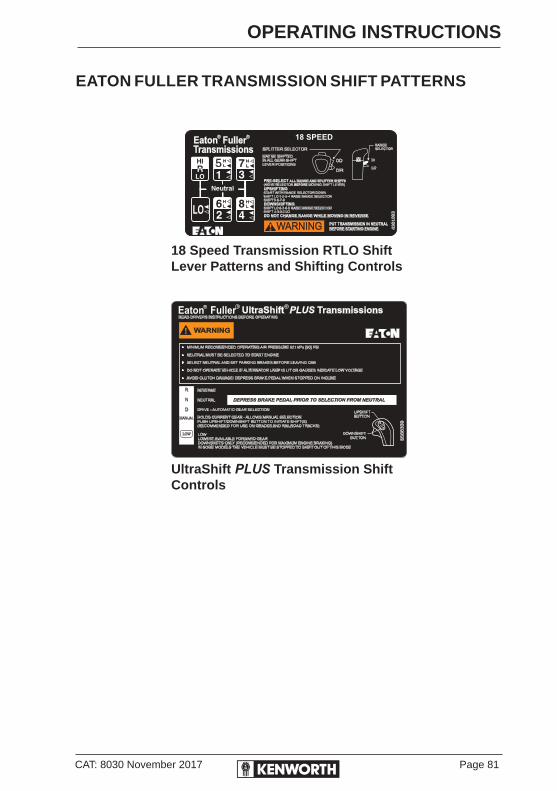
CAT: 8030 November 2017 Page 81
OPERATING INSTRUCTIONS
18 Speed Transmission RTLO Shift Lever Patterns and Shifting Controls
UltraShift PLUS Transmission Shift Controls
UltraShift TransmissionsPLUS
5586339
WARNING
READ DRIVERS INSTRUCTIONS BEFORE OPERATING
MINIMUM RECOMMENDED OPERATING AIR PRESSURE 621 kPa (90) PSI
NEUTRAL MUST BE SELECTED TO START ENGINE
SELECT NEUTRAL AND SET PARKING BRAKES BEFORE LEAVING CAB
DO NOT OPERATE VEHICLE IF ALTERNATOR LAMP IS LIT OR GAUGES INDICATE LOW VOLTAGE
AVOID CLUTCH DAMAGE! DEPRESS BRAKE PEDAL WHEN STOPPED ON INCLINE
REVERSE
NEUTRAL
DRIVE - AUTOMATIC GEAR SELECTION
R
N
D
MANUAL
LOW
DEPRESS BRAKE PEDAL PRIOR TO SELECTION FROM NEUTRAL
HOLDS CURRENT GEAR - ALLOWS MANUAL SELECTIONPUSH UPSHIFT/DOWNSHIFT BUTTON TO INITIATE SHIFT(S)(RECOMMENDED FOR USE ON GRADES AND RAILROAD TRACKS)
LOWLOWEST AVAILABLE FORWARD GEARDOWNSHIFTS ONLY (RECOMMENDED FOR MAXIMUM ENGINE BRAKING)IN SOME MODELS THE VEHICLE MUST BE STOPPED TO SHIFT OUT OF THIS MODE
UPSHIFTBUTTON
DOWNSHIFTBUTTON
RR R
SPLITTER SELECTOR
4301093
RANGESELECTOR
18 SPEEDEaton Fuller
Transmissions
5 H
L
H
L
H
L
H
L
MAY BE SHIFTEDIN ALL GEAR SHIFTLEVER POSITIONS
PRE-SELECT
UPSHIFTING
DOWNSHIFTING
DO NOT CHANGE RANGE WHILE MOVING IN REVERSE
ALL RANGE AND SPLITTER SHIFTS
BEFORE(MOVE SELECTOR MOVING SHIFT LEVER)
START WITH RANGE SELECTOR DOWNSHIFT LO 1-2-3-4 RAISE RANGE SELECTORSHIFT 5-6-7-8
SHIFT LO 8-7-6-5 RAISE RANGE SELECTORSHIFT 4-3-2-1 LO
HI
LO
OD
DIRH
L
EATON FULLER TRANSMISSION SHIFT PATTERNS

Page 82 CAT: 8030 November 2017
OPERATING INSTRUCTIONS
AUTOMATIC TRANSMISSIONS
OPERATING AUTOMATIC TRANSMISSIONSAn automatic transmission makes shifting much easier, but because your truck pulls a heavy load, it is important to use it efficiently. For correct automatic transmission operation, see the manufacturer’s Driver/Operator’s Instruction Manual.
On most automatic transmissions there is no PARK position, so you will need to apply the parking brake before leaving the cab. See Using the Parking Brake, page 98. Do not leave the cab without applying the parking brake. The truck could roll and cause an injury or accident.
Parking BrakeOn a vehicle with no P (Park) position on the transmission shift selector, always put the selector in N (Neutral) and apply the parking brake (or emergency brake if the vehicle is not equipped with a parking brake) to hold the vehicle when it is unattended.
Automatic Transmission RetarderIf your transmission is equipped with this option, it will act like a brake to slow your vehicle without using the brakes. Take your foot off the throttle and operate the retarder switch.
When full retarder effect is not needed, you can apply it intermittently (OFF and ON) to cause gradual or partial slowing.
Continuous application of the retarder will cause the hydraulic fluid temperature to rise. Intermittent application will help prevent overheating.
The service brakes must be used in an emergency. The retarder alone might not stop you fast enough to prevent an accident. The retarder is NOT intended as the primary brake for the vehicle, nor is it an emergency brake. The retarder only helps the service brakes by using pressure to slow the drivetrain. Use the service brakes for quick stops.Do not use the retarder when operating on road surfaces with poor traction (such as wet or loose gravel). Retarders can cause the wheels to skid on a slippery surface. You could lose control of the vehicle and/or jackknife if the wheels begin to skid, resulting in an accident or injury to yourself and/or others.
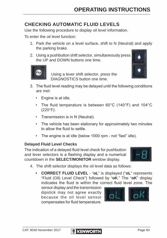
CAT: 8030 November 2017 Page 83
OPERATING INSTRUCTIONS
CHECKING AUTOMATIC FLUID LEVELSUse the following procedure to display oil level information.
To enter the oil level function:
1. Park the vehicle on a level surface, shift to N (Neutral) and apply the parking brake.
2. Using a pushbutton shift selector, simultaneously press the UP and DOWN buttons one time.
Using a lever shift selector, press the DIAGNOSTICS button one time.
3. The fluid level reading may be delayed until the following conditions are met:
• Engine is at idle.
• The fluid temperature is between 60°C (140°F) and 104°C (220°F).
• Transmission is in N (Neutral).
• The vehicle has been stationary for approximately two minutes to allow the fluid to settle.
• The engine is at idle (below 1000 rpm - not “fast” idle).
Delayed Fluid Level ChecksThe indication of a delayed fluid level check for pushbutton and lever selectors is a flashing display and a numerical countdown in the SELECT/MONITOR window display.
4. The shift selector displays the oil level data as follows:
• CORRECT FLUID LEVEL - “oL” is displayed (“oL” represents “Fluid (Oil) Level Check”) followed by “oK.” The “oK” display indicates the fluid is within the correct fluid level zone. The sensor display and the transmission dipstick may not agree exactly because the oil level sensor compensates for fluid temperature.
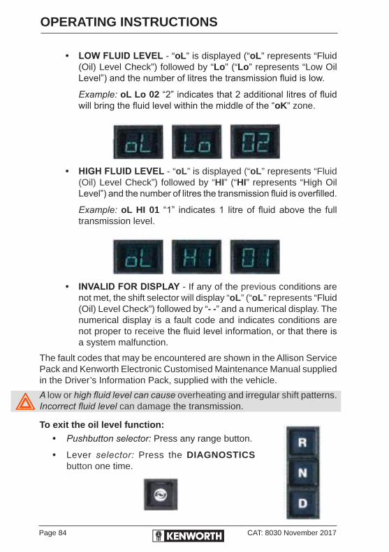
Page 84 CAT: 8030 November 2017
OPERATING INSTRUCTIONS
• LOW FLUID LEVEL - “oL” is displayed (“oL” represents “Fluid (Oil) Level Check”) followed by “Lo” (“Lo” represents “Low Oil Level”) and the number of litres the transmission fluid is low.
Example: oL Lo 02 “2” indicates that 2 additional litres of fluid will bring the fluid level within the middle of the “oK” zone.
• HIGH FLUID LEVEL - “oL” is displayed (“oL” represents “Fluid (Oil) Level Check”) followed by “HI” (“HI” represents “High Oil Level”) and the number of litres the transmission fluid is overfilled.
Example: oL HI 01 “1” indicates 1 litre of fluid above the full transmission level.
• INVALID FOR DISPLAY - If any of the previous conditions are not met, the shift selector will display “oL” (“oL” represents “Fluid (Oil) Level Check”) followed by “- -” and a numerical display. The numerical display is a fault code and indicates conditions are not proper to receive the fluid level information, or that there is a system malfunction.
The fault codes that may be encountered are shown in the Allison Service Pack and Kenworth Electronic Customised Maintenance Manual supplied in the Driver’s Information Pack, supplied with the vehicle.
A low or high fluid level can cause overheating and irregular shift patterns. Incorrect fluid level can damage the transmission.
To exit the oil level function:• Pushbutton selector: Press any range button.
• Lever selector: Press the DIAGNOSTICS button one time.
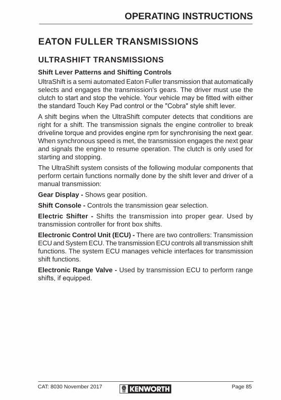
CAT: 8030 November 2017 Page 85
OPERATING INSTRUCTIONS
EATON FULLER TRANSMISSIONS
ULTRASHIFT TRANSMISSIONS
Shift Lever Patterns and Shifting ControlsUltraShift is a semi automated Eaton Fuller transmission that automatically selects and engages the transmission’s gears. The driver must use the clutch to start and stop the vehicle. Your vehicle may be fitted with either the standard Touch Key Pad control or the "Cobra" style shift lever.A shift begins when the UltraShift computer detects that conditions are right for a shift. The transmission signals the engine controller to break driveline torque and provides engine rpm for synchronising the next gear. When synchronous speed is met, the transmission engages the next gear and signals the engine to resume operation. The clutch is only used for starting and stopping.
The UltraShift system consists of the following modular components that perform certain functions normally done by the shift lever and driver of a manual transmission:
Gear Display - Shows gear position.
Shift Console - Controls the transmission gear selection.
Electric Shifter - Shifts the transmission into proper gear. Used by transmission controller for front box shifts.
Electronic Control Unit (ECU) - There are two controllers: Transmission ECU and System ECU. The transmission ECU controls all transmission shift functions. The system ECU manages vehicle interfaces for transmission shift functions.
Electronic Range Valve - Used by transmission ECU to perform range shifts, if equipped.

Page 86 CAT: 8030 November 2017
OPERATING INSTRUCTIONS
Electronic Splitter Valve - Used by transmission controller to perform splitter shifts, if equipped.
Gear Display - Indicates to the driver current selected transmission gear. The display will also flash the target gear when in neutral during a shift.
A solid number on the gear display indicates that the gear is fully engaged.
If flashing down arrows appear on the gear display, this indicates that the input shaft has not slowed down enough to get into gear.
Continue to depress the clutch pedal until the down arrows are off.If the down arrows are off and the gear number continues to flash, slowly let up on the clutch pedal to fully engage the gear.
10-Speed transmission consists of 5-Speed front boxand a 2-Speed rear box. 18-Speed transmission consistsof 5-Speed front box and a 4-Speed rear box
Electric/Pneumatic Range ValvePerforms range shifts
Transmission controller and Harness to control shift functions
Electric/PneumaticSplitter Cylinder
Gear Display
Shows Current Selected Gear

CAT: 8030 November 2017 Page 87
OPERATING INSTRUCTIONS
Push Button Positions Defined
Up/Down Manual
Shift Buttons
R - Reverse
N - Neutral
D - Drive
Manual - Manual gear Selection
Low - Upshift Inhibit with Optimised engine Brake Downshifts
Low feature can be used in any gear."Cobra" Shift Lever
Shift Control selects Driving modeR Reverse Gear is selected. The vehicle does not have to be stopped
to shift into reverse; however, the shift into gear does not occur until the vehicle road speed is under 3.2 km/h and the clutch has been depressed. Do not engage clutch brake while vehicle is moving.
N Neutral is selected. Neutral is used for starting, parking or any stationary operation. No gear is selected. The touch pad/shift lever must be in neutral before engine can be started.
D The transmission selects the starting gear and automatically selects gears between the starting gear and top gear.
M (Manual) Allows the driver to hold current gear and manually select appropriate gear for road conditions using the up/down buttons. The system will not respond to shift requests that would overspeed or excessively lug the engine*.
L Low gear is selected, vehicle is at a stop. Transmission remains in Low gear until Manual or Drive is selected. If the vehicle is moving, transmission downshifts at earliest opportunity for maximum engine braking.*
*UltraShift initiates upshifts from Low and Manual for engine overspeed protection above governed speed.

Page 88 CAT: 8030 November 2017
OPERATING INSTRUCTIONS
Light/Switch Elements DefinedService: The service light alerts the driver of potential transmission problems and service needs. It also assists the technician in problem diagnosis.Upshift/Downshift Buttons: Used in Manual mode to select upshifts and downshifts.
DRIVER DIAGNOSIS - ULTRASHIFTDuring power-up, the service light will come on and go off. This is normal operation. But if the service light comes on and stays on, or comes on while driving, it means UltraShift has detected a fault. Book in to a service facility as soon as possible.
In the event of a problem with the UltraShift, there are three primary tasks the driver should perform:
• Note the driving condition under which the problem occurred.
• Note the condition of the UltraShift under which the problem occurred.
• Retrieve fault codes and reset the UltraShift as described below.
RETRIEVING FAULT CODESRetrieve UltraShift fault codes by enabling the UltraShift system’s self-diagnostic mode.
1. Place the touch pad/shift lever in neutral.
2. Set the parking brake.
3. Turn the ignition key ON but do not start the engine. If the engine is already running, you may still retrieve codes. However, do not engage the starter if engine stalls.
4. To Retrieve Active Codes: Start with the key in the ON position. Turn the key off and on two times within five seconds, ending with the key in the ON position. After five seconds, the service lamp begins flashing two-digit fault codes. If no codes are active, the service light will flash code 25 (no codes).
CAT: 8030 November 2017 Page 89
OPERATING INSTRUCTIONS
5. To Retrieve Inactive Codes: Start with the key in the ON position. Turn the key off and on four times within five seconds, ending with the key in the ON position. After five seconds, the service lamp begins flashing two-digit fault codes. If no codes are active, the service light will flash code 25 (no codes).
6. Observe the sequence of flashes on the indicator lamp and record the codes. A one to two-second pause separates each stored code and the sequence automatically repeats after all codes have been flashed.
DRIVING THE ULTRASHIFT TRANSMISSION
Start-up1. Turn the ignition key to ON and allow the UltraShift to power-up.
Engine cranking is delayed until the transmission power-up is complete and the gear display shows a solid N.
2. Start the engine.
3. Apply service brake.
If the service brake is not applied while selecting a starting gear, the initial start gear will not be found and the driver will have to re-select Neutral and press the brake while re-selecting the desired mode.
4. Release the vehicle parking brakes.
5. Select the desired mode and starting gear on the shift console.
6. Release service brake and apply accelerator.
The transmission is not intended to provide hill-hold capability. The service brakes should be used to stop and hold the vehicle on an incline. To prevent the vehicle from rolling when starting on an incline, place both feet on the brake pedal before sliding the right foot to the throttle pedal. Gradually back off the brake while applying as little throttle as necessary to move along the incline.
Power down1. Select Neutral on the shift control. If gear display does not show
solid N, neutral has not yet been obtained.
2. Set the vehicle parking brakes.
3. Turn off the ignition key and allow the engine to shut down.

Page 90 CAT: 8030 November 2017
OPERATING INSTRUCTIONS
D DRIVE ModeDepending on the transmission model and Shift Control configuration, there may be alternate forward starting gears available. While the vehicle is stopped in Drive, the up/down buttons are used to change the starting gear. This selection is used until it is changed again, or the UltraShift is powered down.
In Drive mode, all upshifts and downshifts are performed automatically, based on vehicle and transmission conditions.
The driver can advance a shift (by about 75 rpm) by pressing the proper up/down button (up for upshifts, down for downshifts) when the transmission is within 75 rpm of the load-based shift point. The Gear Display shows the status of the shift:
• The current gear is displayed solid.
• At the start of the shift, the current gear is displayed solid until the transmission is pulled to the neutral position.
• While the transmission is in neutral and synchronising for the target gear, the target gear is flashed.
• When the shift is complete, the new current gear is displayed solid.
MANUAL Mode• Can be selected while moving or from a stop.
• Must use the up and down buttons to shift.
• Shifter will “beep” if shift cannot be completed due to engine RPM and road speed.
LOW Mode• Can be selected while moving or from a stop.
• Selecting LOW from a stop engages and maintains 1st gear.
• Selecting LOW while moving will allow for downshifts only and downshifts will be performed at higher RPM to maximise engine braking.
“R” REVERSE ModeSelecting REVERSE from NEUTRAL will engage LOW REVERSE. An “R” will appear on the gear display for 10 speed models and an “R1” will appear on the gear display on 13 or 18 speed models.

CAT: 8030 November 2017 Page 91
OPERATING INSTRUCTIONS
Transmission models with multiple reverses must use the up and down arrows to select other reverse gears. Remember to select the proper reverse gear for your load and grade conditions. All reverse gears can only be engaged at less than 3.2km/h.
The UltraShift system may perform automatic shifts in extreme situations (over-speeding the engine or excessively slipping the clutch).
ULTRASHIFT DRIVING TIPS
Proper Starting GearChoose a starting gear appropriate for the load and grade conditions while at a stop in Drive and MANUAL modes by using the up/down buttons. Refer to Drive Mode for detailed information.
Skip ShiftingPerformed in MANUAL by pressing the shift button more than once.
Optimal Engine BrakingThe LOW mode can be selected while moving. This initiates downshifts as soon as possible.
Skid ConditionsIf a skid condition occurs, the UltraShift senses the vehicle speed dropping rapidly. In this case, the UltraShift delays downshifting.
Cruise ControlThe UltraShift is totally compatible with cruise control. If a shift is required while cruise control is active, cruise is temporarily interrupted while the shift is performed and then automatically resumed after the shift.
Load-Based ShiftingIn Drive, the UltraShift will adapt to the changing conditions of the vehicle. Right after power-up or after changing loads, UltraShift needs to learn the new conditions. While learning, it may hold a gear instead of upshifting. Simply push the Up button to start the upshift. It may take three or four shifts for the UltraShift to learn the new conditions. After that it will handle upshifts and downshift automatically.
Depending on conditions, UltraShift can activate the engine brake in order to bring the engine down faster for an upshift. This can happen even if the engine brake dash switch is OFF.

Page 92 CAT: 8030 November 2017
OPERATING INSTRUCTIONS
Coast ModeWhen coasting to a stop in lower gears, UltraShift may not finish downshifting until the driver gets back on the throttle. This is normal for the UltraShift.
Clutch ProtectionAs a driver of a truck equipped with a Fuller UltraShift DM2 Transmission (No Clutch Pedal) please take note of the following message:
Even though your truck does not have a clutch pedal, it still has a mechanical clutch. As you slowly increase and decrease engine RPM from a stop, the clutch is engaging and disengaging, just like slipping the clutch with an AutoShift Transmission or a Manual Transmission.
If the vehicle is operated for long periods between engine idle and 1000 RPM during take off, the driver is slipping the clutch which, in turn, gets the clutch HOT. If the clutch starts to get too hot, a warning tone will sound and a “C” and then an “A” will flash on the gear display (Clutch Abuse) This is an indication that the driver is abusing the clutch and it is getting too hot to operate, potentially resulting in a failure.
If a “C” and then an “A” shows on the gear display during vehicle operation, stop the vehicle for at least two minutes and let the clutch cool down. Continuing operation with the “C” and “A” flashing on the gear display will cause the clutch to become even hotter and the transmission may attempt to downshift into a lower start gear and/or limit the engine to idle speed until the clutch cools (approximately 3 minutes). Repeated incidents of clutch abuse may cause the clutch to fail and render the truck immobile, resulting in extended down time.
Below are some examples of situations which may initiate clutch abuse along with some helpful hints on how to avoid them.
Example How to Avoid
Starting on hills using the throttle rather than the brake
Use the service brakes to hold on a hill. To start moving, apply the throttle and release the brakes as you feel the truck start to pull.
M o v i n g t r a i l e r tandems
Be sure to always start off in 1st gear when moving forward, and Low Reverse when moving backwards (R or R1 on gear display)
Hooking up to a trailer Always be sure the trailer is high enough to back under. Use Low reverse (R or R1 on gear display). Use light brake pedal pressure to reduce the "jerking" of the vehicle.
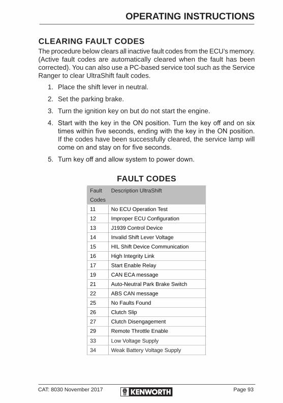
CAT: 8030 November 2017 Page 93
OPERATING INSTRUCTIONS
CLEARING FAULT CODESThe procedure below clears all inactive fault codes from the ECU’s memory. (Active fault codes are automatically cleared when the fault has been corrected). You can also use a PC-based service tool such as the Service Ranger to clear UltraShift fault codes.
1. Place the shift lever in neutral.
2. Set the parking brake.
3. Turn the ignition key on but do not start the engine.
4. Start with the key in the ON position. Turn the key off and on six times within five seconds, ending with the key in the ON position. If the codes have been successfully cleared, the service lamp will come on and stay on for five seconds.
5. Turn key off and allow system to power down.
FAULT CODESFault
Codes
Description UltraShift
11 No ECU Operation Test
12 Improper ECU Configuration
13 J1939 Control Device
14 Invalid Shift Lever Voltage
15 HIL Shift Device Communication
16 High Integrity Link
17 Start Enable Relay
19 CAN ECA message
21 Auto-Neutral Park Brake Switch
22 ABS CAN message
25 No Faults Found
26 Clutch Slip
27 Clutch Disengagement
29 Remote Throttle Enable
33 Low Voltage Supply
34 Weak Battery Voltage Supply

Page 94 CAT: 8030 November 2017
OPERATING INSTRUCTIONS
Fault
Codes
Description UltraShift Cont....
35 J1939 Communication Link
36 J1939 Engine Message
37 Power Supply
41 Range Failed to Engage
43 Range Solenoid Valve
45 Inertia Brake Performance
51 Rail Position Sensor
52 Gear Position Sensor
56 Input Shaft Sensor
57 Main Shaft Sensor
58 Output Shaft Sensor
61 Rail Motor Circuit
63 Gear Motor Circuit
64 Electronic Clutch Actuator (ECA)
65 ECA Speed Sensor
66 ECA Battery Vol;tage
67 ECA Ignition Voltage
68 Grade Sensor
71 Unable to Disengage Gear
72 Failed to Select Rail
73 Failed to Engage Gear
74 Engine Speed Response Fault
Engine Torque Response FaultShift Quality
75 Power Down in Gear
81 Gear Engagement Detected
83 Shift Lever Missing
84 Shift Controller Device not Configured
85 Shift Control Device Incompatible
99 Direction Mismatch
An 88 code may appear in gear display which indicates self testing.

CAT: 8030 November 2017 Page 95
OPERATING INSTRUCTIONS
ULTRASHIFT PLUS TRANSMISSIONS
Shift Console PositionsR Selects Reverse
N Mode used for Start-up and Power- down
D Selects Drive
Manual Selects Manual
Low Selects Low
Service The service indicator alerts the driver of potential transmission problems.
Up/Down Used in the MANUAL mode to select upshifts and downshifts and to change start gear, if available.
PTO Power Take Off is activated and transmission is ready for PTO operation. (See “Transmission Power Take Off” in Driver Information Pack for details.)
Gear DisplayThe Gear Display shows the current gear position of the transmission. The Gear Display will flash the target gear position of the transmission when in neutral during a shift.
Satisfactory engagement in 4th gear
Out of gear waiting for engine/trans rpm to reach
synchronous
Satisfactory engagement in 5th gear
SOLID FLASHING SOLID
The “DASH” indicates the transmission may be torque locked in gear. (See “Service and Maintenance Locked in Gear” section for more details.)
4 5 5
-
Buttons
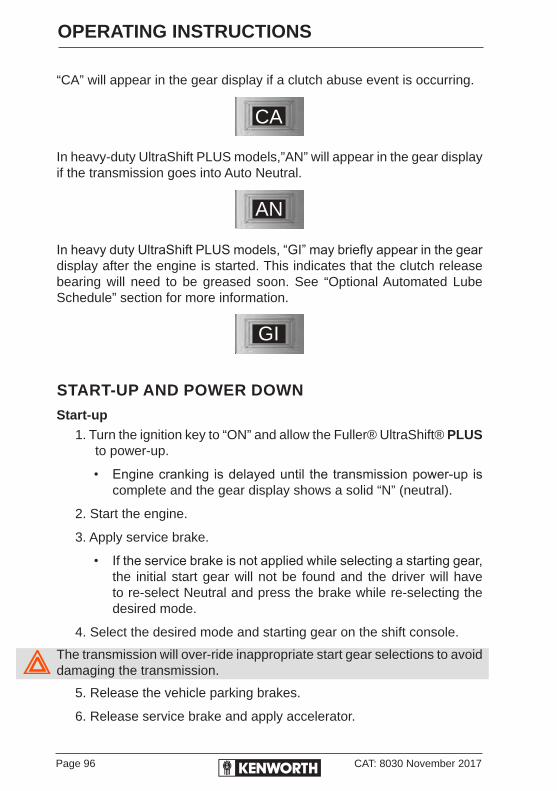
Page 96 CAT: 8030 November 2017
OPERATING INSTRUCTIONS
“CA” will appear in the gear display if a clutch abuse event is occurring.
In heavy-duty UltraShift PLUS models,”AN” will appear in the gear display if the transmission goes into Auto Neutral.
In heavy duty UltraShift PLUS models, “GI” may briefly appear in the gear display after the engine is started. This indicates that the clutch release bearing will need to be greased soon. See “Optional Automated Lube Schedule” section for more information.
START-UP AND POWER DOWN
Start-up1. Turn the ignition key to “ON” and allow the Fuller® UltraShift® PLUS
to power-up.
• Engine cranking is delayed until the transmission power-up is complete and the gear display shows a solid “N” (neutral).
2. Start the engine.
3. Apply service brake.
• If the service brake is not applied while selecting a starting gear, the initial start gear will not be found and the driver will have to re-select Neutral and press the brake while re-selecting the desired mode.
4. Select the desired mode and starting gear on the shift console.
The transmission will over-ride inappropriate start gear selections to avoid damaging the transmission.
5. Release the vehicle parking brakes.
6. Release service brake and apply accelerator.
GI
AN
CA
CAT: 8030 November 2017 Page 97
OPERATING INSTRUCTIONS
Power Down1. Select Neutral on the shift control.
• If gear display does not show solid “N,” neutral has not yet been obtained.
Neutral should always be reached before the Fuller UltraShift PLUS power down is performed except in cases of emergency.
2. Set the vehicle parking brakes.
3. Turn off the ignition key and allow the engine to shut down.
Reverse Mode• Selects default Reverse gear (see Note* below).
• Each time Reverse is selected from Neutral, the default Reverse gear is engaged.
• The vehicle will not engage Reverse above 3.2km/h.
• On multi-speed auxiliary models, R1 to R2 and R3 to R4 shifts will only be made by manually using up and downshift buttons while driving.
• Single-speed auxiliary (10-speed) and medium-duty models have only one reverse speed.
You cannot range shift while moving, but you can split shift while moving if the vehicle is equipped with a multi-speed auxiliary section.
R4 is only available on the UltraShift PLUS Multipurpose Extreme Performance (MXP) and UltraShift PLUS Vocational Extreme Performance (VXP) models.*If you attempt to select a non-neutral mode without depressing the service brakes the transmission will not shift into gear and you will have to return to Neutral and depress the brakes before selecting the desired mode again.

Page 98 CAT: 8030 November 2017
OPERATING INSTRUCTIONS
Fuller UltraShift PLUS Linehaul Active Shifting (LAS)
LO Range
Fuller UltraShift PLUS Multipurpose High Performance (MHP)
LO Range - LO Split
LO Range - HI Split
HI Range - LO Split
Fuller UltraShift PLUS Vocational Construction Series (VCS) and
Fuller UltraShift PLUS Vocational Multipurpose Series (VMS)
LO Range - DR LO LO Range - DR HI HI Range - DR HI
Fuller UltraShift PLUS Multipurpose Extreme Performance (MXP) and
Fuller UltraShift PLUS Vocational Extreme Performance (VXP)
LO RangeLO Split
LO RangeHI Split
HI RangeLO Split
HI RangeHI Split
R
R1 R2 R3
R1 R2 R3
R1 R2 R3 R4
CAT: 8030 November 2017 Page 99
OPERATING INSTRUCTIONS
USING THE BRAKE SYSTEMThe operation of the vehicle’s braking system and many vehicle accessories depends on the storage and application of a high-pressure air supply.
The air brake system contains dual circuits: a circuit for the rear brakes (primary) and a circuit for the front brakes (secondary). The trailer air is supplied from these two circuits. The system is supplied by an engine-driven compressor. The vehicle’s compressor takes outside air and compresses it, usually to 690-896 kPa. The compressed air then goes to the reservoirs to be stored until needed.
Upon operation of the service brake, stored air flows from the air tanks to the brake chambers. The pressure of this delivered air is regulated through the foot valve. There is no direct force applied to the air by foot pressure.
In hydraulic braking systems, such as cars, force applied to the brake pedal is transferred directly to the hydraulic fluid. As fluid is virtually incompressible, this gives the feeling of a firm brake pedal. You will not feel this in a pneumatic brake system as used in trucks, because the operator is simply operating a valve.
The brake system is a critical vehicle safety system. For the safety of yourself and others around you, have the vehicle submitted for periodic preventive maintenance checks as well as having any suspected problems immediately checked by an Authorised Service Centre. Failure to properly maintain your brake system can lead to serious accident and/or injury.
Never drive your vehicle with the parking brake applied. Always release the parking brakes prior to moving the vehicle. Failure to disengage the parking brakes prior to moving your vehicle could result in excessive heat build-up in the brake system, resulting in a fire.Today’s diesel electronic engines have significant torque and startability power at low rpm. Combinations of engine speed and available torque may over-power the vehicle’s parking brakes.
AIR SUPPLY SYSTEMContamination of the air supply system is the major cause of problems in air-operated components such as brake valves and suspension height control valves. To keep contaminants to the lowest possible level, follow all maintenance procedures.

Page 100 CAT: 8030 November 2017
OPERATING INSTRUCTIONS
BRAKE OPERATIONDo not drive through water deep enough to wet brake components, as it may cause the brakes to work less efficiently than normal. The vehicle’s stopping distance may be longer than expected and the vehicle may pull to the left or right when brakes are applied, which could contribute to an accident.
To rectify this condition, check the rear and both sides of the vehicle for clear traffic, then apply the brakes gently, releasing and gently reapplying until the brakes dry out and normal operation is restored. Always check brakes after driving through deep water to help reduce the possibility of personal injury or an accident.
Front Brake SystemWhen the brake pedal is depressed, the front circuit portion of the treadle valve delivers air from the front service reservoir to the front axle brake chambers via a quick-release valve.Simultaneously (on-full truck configurations) air is also supplied to the modulating valve control port. In the event of a rear service circuit failure, the modulating valve will exhaust air from the spring brake chambers, applying the spring brakes in proportion to the front circuit application.
Rear Brake SystemWhen the brake pedal is depressed, the rear circuit portion of the treadle valve delivers air from the rear service reservoir to the service brake relay valve control port. The relay valve then delivers air directly from the rear service reservoir to the rear brake chambers (via the ABS pressure control valve if ABS is fitted) in proportion to the treadle pressure.Brake Application Air Gauge
The Brake Application Air gauge will show you how much air pressure is being applied from the foot brake valve or trailer brake hand valve to the air brakes. It is a mechanical gauge which is connected to the brake valve.
USING THE PARKING BRAKEThe yellow diamond-shaped knob on the dash controls the truck parking brakes. These are spring brakes that you activate by releasing air pressure from their chambers. When they are not in use, air pressure compresses the springs and releases the brakes. Pulling the valve OUT applies the parking brake, which exhausts air from the chambers and allows the springs to extend and apply the brakes.

CAT: 8030 November 2017 Page 101
OPERATING INSTRUCTIONS
Do not leave the cab without applying the truck parking brake. The truck could roll and cause an injury or accident.
BEFORE YOU LEAVE THE CAB1. Apply parking brake. Pull out the Yellow Parking Brake Control knob
located on the dash. The red Trailer Air Supply Control valve will automatically apply.
2. Shift the transmission into PARK position:
• Manual transmission, select Neutral.
• UltraShift & Automatic transmission, select Neutral.
3. Turn the key to the OFF position and remove the key.
The parking brakes act on the rear wheels only. They are spring-applied, with air pressure used to release them.
Release air is supplied by both the front and rear circuit reservoirs through a double check valve.
Trailer park brake is not intended to be used as park brake for truck and trailer combination. The truck could roll and cause an injury or accident.
TO RELEASE THE TRUCK PARKING BRAKES ONLY• Push IN the yellow knob on the dash. Your trailer will remain
parked.
• Below the threshold pressure the Yellow valve remains OUT (in the ON position) when you attempt to push it in.
See Air System Pressure Gauges on page 36 for more information.
TO RELEASE THE FULL COMBINATION OF BRAKES• Push IN BOTH knobs on the dash.
• If the air pressure is reduced below a safe level, the low-air warning light will come on first. If air pressure continues to drop the parking brake valve will pop OUT, automatically applying the spring brakes.
Do not try to put the vehicle in motion before pressure in the system reaches 689 kPa, because the wheels are locked by the spring brake action.

Page 102 CAT: 8030 November 2017
OPERATING INSTRUCTIONS
Unnecessary stress and possible brake malfunction could occur if the vehicle is forced to move before the air system reaches 689 kPa.
If air pressure drops below the spring brake (Yellow) threshold pressure, the spring brakes may stop the vehicle abruptly, which could result in an accident and/or injuries. Observe the red warning lamps on the gauges. If one comes on, do not continue to drive the vehicle until it has been properly repaired or serviced.
TRUCK/TRAILER AIR SUPPLY VALVEInitial ChargeThe red octagonal knob controls the air supply to the trailer. With the system completely discharged, both the red (trailer air supply) and the yellow (parking brake) knobs are OUT; thus, truck and trailer parking (spring) brakes are applied.
Allow the truck air system pressure to build up to operating level.
Normal Run Position• The yellow knob (system park) may now be pushed IN, which will
supply air to the truck spring brakes, releasing them.
• The red knob may now be pushed in to charge the trailer system.• With both knobs pushed IN, air is now being supplied to both the
trailer and the truck spring brakes; all brakes are released.
Trailer Park or Emergency Brake Application OnlyIf you ever have a failure or disconnect the air supply hose to the trailer, the trailer parking brakes will set. The red knob will automatically pop OUT and seal off the truck air reservoirs to protect the truck air system pressure.To apply the trailer brakes only: Pull OUT the red knob. This will exhaust air from the trailer supply line, causing the truck protection valve to close and the trailer spring brakes to apply. The trailer is now in “emergency” or “park”. This mode would be used to uncouple from the trailer and during bobtail operation (running without a trailer connected).
Do not use the trailer hand brake or service brakes to park and hold an unattended vehicle. Use the parking brakes. Because service brakes work with air pressure, these brakes could slowly release. Your vehicle could roll and cause a serious accident. Someone could be hurt or killed. Never rely on the service brakes to hold a parked vehicle.
CAT: 8030 November 2017 Page 103
OPERATING INSTRUCTIONS
TRAILER PARK BRAKE RELEASE VALVEThe trailer park release valve is an optional fitment, for use with semi/full rear tipping trailers.
The trailer park release valve is interlocked with the main park brake system, per ADR 35/03 requirements. The trailer brakes can only be released after all the park brakes have activated and stabilised.
The engine must be running for the system to operate (Engine oil pressure switch controlled) and not moving.
The basic operation of the trailer is that the tipping motion “drags” the trailer forwards toward the truck due to the effective shortening of the drawbar as the tip angle increases. If the trailer brakes are applied, this would then cause the tyres of truck/trailer be dragged backwards.
The basic sequence of operations is:• Reverse trailer into position and then apply the park brakes for the
complete truck/trailer combination.
• Release trailer park brakes by activating the “black valve”, then activate the tilt mechanism.
• Once tilt cycle is completed, release system park brake to move off, this deactivates the trailer release valve.
The trailer park release valve operates, once complete combination park brakes applied, by supplying air only to the trailer parking brakes to release them. At the same time, because the combination park brakes have been activated, the foot pedal controlled service air brake system is inoperative.
WARNINGThe trailer park brake release valve is only designed to be used by the driver during tipping. DO NOT leave the driving position while activated.
Only operate on relativly flat ground, if the truck brakes are insufficient to hold the combination, release the park brakes and operate the service brakes

Page 104 CAT: 8030 November 2017
OPERATING INSTRUCTIONS
SYSTEM TRUCK PARKWith both knobs pushed in for normal operating modes, the parking brakes of both the truck and the trailer may be applied by pulling the yellow knob OUT. This will exhaust the air from the truck spring brakes, and simultaneously cause the red knob to pop OUT, which will apply the trailer brakes. This complies with the ADR 35/03 requirement that one control should apply all the parking brakes on the vehicle.
BRAKE SAFETY AND EMERGENCYDo not operate the vehicle in the event of a malfunction in any air circuit. The vehicle should not be operated until the system is repaired and both braking circuits, including all pneumatic and mechanical components, are working properly. Loss of system air can cause the service brakes to not function, resulting in the sudden application of the spring brakes, causing wheel lock-up, loss of control or collision by following vehicles. Loss of air system could result in an accident and/or personal injury.
If pressure is lost in the truck front or rear circuit, the “check” valves isolate the unaffected circuit, allowing this circuit to continue normal operation. The trailer brakes are still functional.
• If air pressure is lost in the trailer supply/park circuit, and the pressure drops below the threshold pressure, the trailer spring brakes are automatically applied, and the truck air pressure circuits are unaffected.
• If air pressure is lost in the trailer brake service circuit, and the pressure in the truck front and rear circuits drops below threshold pressure, the truck and trailer spring brakes are automatically applied.
EMERGENCY BRAKINGUnless you have an anti-lock braking system (ABS), always avoid completely depressing the service brake pedal, if possible, even during emergency braking. Depressing the brake pedal too aggressively can cause the wheels to lock, which can lead to an uncontrolled skid and can result in an accident.

CAT: 8030 November 2017 Page 105
OPERATING INSTRUCTIONS
FOR NON-ABS VEHICLESTo stop your vehicle in an emergency, vary the service brake application pressure to provide maximum braking force without locking the wheels. Use engine compression to assist the service brakes by not depressing the clutch pedal until the engine reaches idle speed.
Overheated BrakesUnder normal braking conditions, the energy generated will bring the internal brake drum temperature to about 260°C. This is well within the safe zone. The maximum safe temperature of linings for drum type brakes is usually about 427°C.
If service brakes are used improperly for prolonged periods or for emergency braking, internal brake drum temperatures may exceed 427°C. Such brake overheating may be detected by a burning smell or smoke coming from a drum. If this occurs, you should immediately stop and check for cracked brake drums or lining fires. If neither exists, get back behind the wheel and resume at slow speed as soon as possible to cool the brakes.
If the vehicle were to remain stopped, the heat transfer could destroy the linings and distort the brake drum.
To prevent drums from distorting while they cool down:• Park the vehicle on level surface and block the wheels.
• Release the parking brake and allow the brakes to cool down. See Using the Parking Brake on page 99.
DISC BRAKESThe air disc brakes are high performance, low weight, high efficiency brakes designed for trucks and other commercial vehicles requiring between 10,000 and 23,000 Nm of braking torque at each wheel.Clamping force is produced by a globular cast iron caliper located above the rotor and housing two lining pads. The pads are pushed against the rotor by a dual piston actuating block connected to an eccentric shaft, which is in turn driven by a lever operated by a standard air actuator (rotation chamber).
The caliper is carried on a saddle which is a fixed support bolted to the axle flange.Equalised clamping action both on the inner and outer pads is generated by allowing the caliper to float on the two slide pins fixed to the saddle.

Page 106 CAT: 8030 November 2017
OPERATING INSTRUCTIONS
Clamping force generated by the primary actuation is applied to the inner pad which forces it into contact with the rotor. Reactive force through the caliper body applies equal clamping force to the outer pad applying a balanced clamping force to the rotor.
The slide pins also allow the caliper to freely position itself on the saddle to compensate for the reduction in lining pad thickness due to wear. An automatic self-adjuster mechanism is incorporated in order to maintain constant clearance between pads and rotor.
The automatic adjuster operates on each clamping action to sense excessive pad-rotor clearance, and reduces excessive clearance by a fixed proportion with each actuation.For brake adjustment and new lining installation, the brake incorporates provision for manual adjustment, easily performed by using a standard hexagonal wrench.
Brake actuation can be either clockwise or counterclockwise, depending on how the rotation chamber has been installed on the brake unit.
EBSS - ELECTRONIC BRAKE SAFETY SYSTEM
ANTI-LOCK BRAKING SYSTEM (ABS)Your Kenworth may be equipped with an anti-lock braking system (ABS). The ABS reduces the possibility of wheel lock-up. If a wheel is about to lock during braking, the ABS will automatically adjust air pressure to the brake chambers on the appropriate wheel(s) to prevent wheel lock-up. The ABS is automatically turned on when the ignition switch is turned on.
ABS WARNING LAMPDo not rely on an anti-lock brake system that is functioning improperly. You could lose control of the vehicle, resulting in a severe accident and/or personal injury. If your ABS lamp comes on while you are driving, or stays on after the self-check, your anti-lock system might not be working. The ABS may not function in an emergency. You will still have conventional brakes, but not anti-lock brakes. If the lamp indicates a problem, have the ABS checked.If the ABS warning light does not illuminate when the ignition is first turned on, there is a problem with the bulb or wiring. You should have this checked as soon as possible.
CAT: 8030 November 2017 Page 107
OPERATING INSTRUCTIONS
The ABS warning lamp will come on momentarily when the key switch is first turned. The lamp will go out and stay off unless the system detects a failure or malfunction.
Except for checking the proper illumination of the ABS and wheel spin control warning lamps when first starting the truck, and for monitoring these lamps while driving, no special operating procedures are required. For a detailed system description, see operation and service literature for your specific ABS.
ATC - AUTOMATIC TRACTION CONTROLATC is a standard feature of the ABS system. This feature is monitored by a wheel spin control warning lamp. As such, the system consists of Wheel Speed Sensors (WSS), Electronic Control Unit (ECU) and Pressure Modulation Valves (PMV) and in addition, an Automatic Traction Control Valve (ATC Valve).
The traction control warning lamp will briefly illuminate and then go out when the ignition switch is first turned on. The traction control warning lamp will illuminate whenever the ATC system detects drive wheel spin. The lamp will remain illuminated as long as wheel spin is detected and the ATC system is applying the drive wheel brakes or reducing engine torque.Do not allow the traction control lamp to remain on continuously for an extended length of time. Extended, continuous use of the ATC can cause overheating of the drive wheel brakes. Engine torque or vehicle speed should be reduced to eliminate wheel spin and prevent excessive application of the ATC system.
ATC is used for slip control of the driven wheels. Under acceleration, one or more of the driving wheels may start to spin as the drive torque exceeds the drive tyre to road surface adhesion. ABS responds to braking by inhibiting wheel lock, ATC reacts to acceleration by holding acceleration slip within acceptable levels to prevent wheel spin.
The ATC system communicates with the engine ECU via the J1939 data bus. In the event of a wheel slip incident both engine and ATC systems operate simultaneously to reduce engine torque/RPM and apply or release pressure in the service brake system to prevent wheel slip or spin.
The ATC system sensitivity can be reduced by enabling the ATC Off Road switch.
Page 108 CAT: 8030 November 2017
OPERATING INSTRUCTIONS
If the ATC Off Road switch is enabled, the ATC sensitivity threshold will be decreased up to a speed of approximately 50 km/h, at which normal ATC operation will automatically resume.
Optional features of the Electronic Brake Safety System are outlined below, and a more comprehensive section is located on the CD in the Driver's Information Pack.
DTC - DRAG TORQUE CONTROLPremium EC-60 controllers have a feature referred to as drag torque control which reduces wheel slip on a driven axle due to driveline inertia. This condition is addressed by increasing the engine torque to overcome the inertia. Drag torque control increases vehicle stability on low traction road surfaces during down-shifting or retarder braking.
ESP - ELECTRONIC STABILITY PROGRAMESP helps to restore vehicle stability through the use of ABS, ATC, steering direction and vehicle directional stability information. Steering angle, yaw, suspension pressure and brake application pressure sensors monitor the intended vehicle directional control versus actual vehicle movement. ESP intervenes by applying individual wheel brakes, or reduced engine torque when required to enhance vehicle stability. The system is compatible with multi trailer combinations.
TRM - TRAILER RESPONSE MANAGEMENTElectronic trailer brake actuation (for EBSS compatible trailers only) for improved trailer braking response to assist with reduced stopping distances.
ACB - ACTIVE CRUISE WITH BRAKESACB helps assist with accident avoidance, by using on board computers and radar to engage the engine and wheel braking systems if other vehicles on the road enter unsafe distances from the truck.
The Active Cruise with Braking system features Collision Mitigation, which will apply up to 2/3 of vehicle braking power if an object is detected in the vehicle’s path, with or without cruise control being enabled.
Collision Mitigation provides audible and visual alerts to the driver and applies th brakes when the system determines a collision with a forward vehicle is imminent.

CAT: 8030 November 2017 Page 109
OPERATING INSTRUCTIONS
When crusei control is active and in the event of a potential collision whilst cruise control is active, teh truck will firstly de-throttle, depending on the severity of the event the engine brake will automatically apply, if this does not slow the truck, the service brakes would be applied up to 2/3 of the total brake application.
Collision mitigation DOES NOT require cruise control to be active. If the ACB system deems a collision is imminent, the system will give you a visual warning and apply up to 2/3 of total service brake application.
ACB also includes Stationary Object Alert, whihc provides an audible and visual warning to the driver if any stationary metallic object is detected in the vehicle path.
OFF-ROAD FUNCTION
ABS OFF-ROAD FUNCTION SWITCHYour Kenworth vehicle may be equipped with a separate electrical switch to activate an ABS off-road function. This function is NOT to be used for on-highway driving, but is intended to be used to improve stopping performance in off-highway conditions (e.g. loose gravel and mud). The ABS off-road function is accomplished by not allowing a “wedge” of material to build-up in front of momentarily locked wheels.
Features and Benefits• Changes the ABS control limits to allow for a more aggressive ABS
function while off-road.
• Improves vehicle control and helps reduce stopping distances in off-road conditions or on poor traction surfaces such as loose gravel, sand and dirt.
• Allows retarders to function independently of the ABS function.
• If your vehicle does not have an engine retarder, the ABS off-road switch will function the same.
While the off-road mode can improve vehicle control and shorten stopping distances, some steering ability may be reduced on certain surfaces resulting from the momentarily sliding tyres. Always operate your vehicle at safe operating speeds. Failure to do so might cause your vehicle to lose control and could result in an accident and/or injury.
ABS/ATCOFF ROAD

Page 110 CAT: 8030 November 2017
OPERATING INSTRUCTIONS
Never drive your vehicle on improved roads/highways with the ABS off-road function turned on. When you drive your vehicle onto an improved road surface/highway, immediately turn off the ABS off-road switch. Failure to do so will cause the ABS system to not function properly if required and could result in an accident and/or injury.
• The ABS lamp flashes slowly during off-road mode engagement. This is done to alert the driver of a modification to the ABS control software.
• At speeds above 40 km/h, the ABS controller automatically switches back to normal on-highway control mode.
• At speeds between 16 and 40 km/h, the ABS control software is modified to allow short periods (0.25 seconds) of locked-wheel cycles.
• At speeds below 16 km/h, the ABS control software is turned off to allow locked wheels.
• When the ABS off-road function is enabled, the retarder disable output is turned off. That is, the engine retarders are left to function without ABS intervention.
For more information explaining individual EBSS elements, see the Electronic Customised Maintenance Manual, section 4 - Braking, for vehicles with EBSS read either BW2428 or BW2429 as specified.
HILL START ASSIST (HSA)Vehicles fitted with Eaton UltraShift Plus transmissions also have the Hill Start Assist feature, HSA defaults to the ON position. It can be turned OFF by pressing and releasing the HSA switch, however, it will turn back ON after the first successful launch. If the switch is turned OFF, the lamp in the HSA switch will flash.
• Vehicle must be on incline greater than 3% and in a forward mode.
• Bring vehicle to a stop and depress the service brakes then release the service brakes.
Vehicle will begin to move after 3 seconds, and the clutch will perform partial engagements to slow the vehicle motion. You must either step on the brake or apply the throttle.
HSA

CAT: 8030 November 2017 Page 111
OPERATING INSTRUCTIONS
AUTOVUE® LANE DEPARTURE WARNING (LDW) SYS-TEM BY BENDIX CVSThe AutoVue® Lane Departure Warning (LDW) System by Bendix CVS (optional) gives fleet operators the ability to combat lane drift related to drowsiness/fatigue, distractions and adverse/unfavourable weather conditions. The AutoVue system, using a camera with a 60° field of view that tracks visible lane markings including both solid and dashed shoulder lines, center lines and lines between lanes, detects when a vehicle begins to drift towards an unintended lane change.
The system components include a digital camera mounted near the middle of the windshield inside the cab and a central processing unit in the overhead console. When an unexpected lane change takes place, lane changes without an activated turn signal in the direction the vehicle is headed, the sytem alerts the driver to make a correction. Optimised to reduce false alarms, the system automatically emits a distinctive ‘rumble strip’ or other warning using speakers or, if a non-audible warning is preferred, a vibrating seat, alerting the driver to mamek a correction.
Carefully read the information provided. The AutoVue LDW system is intended only as an aid for a conscientious and alert driver. It may not provide any warning of unintended lane departures under certain conditions, see page 112. Do not rely solely on the system to safely operate the vehicle. It does not warn of all possible hazards. For example, the system cannot help prevent an accident if the driver is impared or not driving safely.
Bendix active and supportiver safety technologies, including AutoVue LDW, do not replace the need for safe drivers. No commercial vehicle safety technology replaces the most important safety components of all, a skilled, alert professional driver, reacting appropriately and in a timely manner, using safe driving habits, as well as continuous, comprehensive driver training.
It is the responsibility of the driver to change driving styles depending on traffic and road conditions.

Page 112 CAT: 8030 November 2017
OPERATING INSTRUCTIONS
SYSTEM OPERATION:
Starting the vehicle supplies power to the system. On start-up, the system performs a self-test, then sounds two chirps through the speakers or vibrations for systems with vibrating seats to indicate the system is ready. Once the vehicle is running and the system is ready, the green ENABLED lamp illuminates. The ENABLE/DISABLE switch on the instrument panel temporarily suppresses the alarms. Pushing the switch once disables the system; pushing the switch again re-activates the system. The system will automatically re-activate itself 15 minutes after it has been manually disabled. When enabled, the amber LANE SEARCHING status lamp illuminates to indicate the system is powered, but not actively alerting the driver at this time.
Examples of conditions that can illuminate the amber lamp:
• If the vehicle speed is less than 60km/h.
• When lane markings are undetectable.
• If a dirty windshield, or a similar problem, is obscuring the camera.
• When a sytem Diagnostic Trouble Code (DTC) is detected.
While the system is capable of detecting many different types of lane markers, its performance may be diminished by certain conditions, including:
• Road surfaces that are broken or obscured by dirt, sand, salt, gravel or skid marks.
• Weather conditions, such as rain, snow, ice, mud or fog, diminish the visibility the visibility of the road surface.
• Lane markings that are damaged, worn or faded.
• Poor lighting, such as heavy glare or if the vehicle had an inoperable headlight.
• A windshield that is cracked, dirty or streaked.
The AutoVue LDW system by Bendix CVS is not meant for use in city traffic, in cinstruction zones or in heavy highway traffic. It does not provide warnings for planned lane departures indicated by an activated turn signal and disables warnings when driving below 60km/h.
CAT: 8030 November 2017 Page 113
OPERATING INSTRUCTIONS
The AutoVue LDW system is optimised to reduce false alarms, however the driver may temporarily use the ENABLE/DISABLE switch to silence the alarm if the current road conditions are causing multiple false alarms.
Under normal road conditions, when driving above 60km/h, if the amber LANE SEARCHING lamp illuminated for a long period of time and the green ENABLED lamp remains off despite depressing the ENABLE/DISABLE switch, the system requires calibration service at a dealer or authorised service facility.
AutoVue® text supplied by Knorr-Bremse AustraliaPty Ltd.
TRAILER BRAKE HAND VALVEThis hand valve provides air pressure to apply the trailer brakes only. It operates independently of the foot treadle valve.
To operate the trailer brake hand valve:
• Pull down on the lever under the right side of the steering wheel.
For trucks delivered to NZ, this valve is self-returning. When pressure is removed from the valve lever, it will return to the OFF position.
For Australian delivered trucks, this valve is manually operated. Pull downward to apply and push upwards to release the trailer brakes, independent of the truck brakes.
The trailer brake is not to be used as a substitute for the service brakes. Using this brake frequently, instead of using the foot brake, will cause the trailer brakes to wear prematurely.
DRIVING BOBTAIL OR WITH AN UNLOADED TRAILERThe following information is applicable only to truck and trailer configurations.Do not use the engine retarder (for example engine brake) to slow the vehicle down when you are bobtail or pulling an empty trailer.
Using engine retarders while bobtailing or with an unloaded trailer can cause a wheel lock-up resulting in less control and/or a jackknife. The trailer may not load the rear truck tyre enough to provide necessary traction. When you are bobtail or unloaded, you can have a serious accident if your wheels lock suddenly during braking.
Page 114 CAT: 8030 November 2017
OPERATING INSTRUCTIONS
VEHICLE RETARDERSThe service brakes must be used in an emergency. The engine or retarder alone might not stop you fast enough to prevent an accident.
The engine retarder is NOT intended as the primary brake for the vehicle, nor is it an emergency brake. The engine retarder only helps the service brakes by using pressure to slow the drivetrain. Use the service brakes for quick stops.A variety of engine retarders or exhaust brakes may be installed (as an option) to create a braking effect on the drive wheels. These devices use your engine’s power to slow your vehicle down. Because they can help keep your vehicle’s brakes from overheating, they save wear and tear on the service brakes. However, the retarder is not an emergency brake.
Ideally (on normal road surfaces) you should slow your vehicle with the retarder (where permitted by law) and use the service brakes only for stopping completely. Operating this way will greatly prolong the life of the brakes.
EXHAUST BRAKENOTE: The exhaust brake and engine brake are two different types of engine retarders. See your Engine Operation and Maintenance Manual and Engine Retarder or Engine Brake Operation Manuals for further details on using these types of engine retarders.
With the exhaust brake switch ON, the brake automatically creates its braking effect when you remove your foot from the accelerator pedal. The engine brake switch is located on the accessory dash panel. It controls whether the brake is ON (ready to slow the vehicle down) or OFF (no braking action).
Make sure the brake is OFF before starting the engine.
After the engine is started, warmed up, and you are ready to get under way, turn the exhaust brake switch ON for added braking effect.Do not use the exhaust brake when operating on road surfaces with poor traction such as wet, icy, or snow covered roads or gravel. Retarders can cause the wheels to skid on a slippery surface. You could lose control of the vehicle and/or jackknife if the wheels begin to skid, resulting in an accident.
If your vehicle is equipped with anti-lock brakes (ABS), the operation of the exhaust brake (if turned ON) will be controlled by the ABS. For further details on how to use the exhaust brake, see the exhaust brake manufacturer’s Owner’s Manual.
CAT: 8030 November 2017 Page 115
OPERATING INSTRUCTIONS
ENGINE BRAKESThe engine retarders most commonly installed on Kenworth vehicles are manufactured by Cummins and are known as the “C-Brake”. See your Engine Operation and Maintenance Manual and Engine Retarder or Engine Brake Operation Manual for further details on using these types of engine retarders.
A master switch located on the steering wheel turns the system ON or OFF. The switch also controls the braking effect. This switch allows you to choose progressively stronger retardation to slow the vehicle down.
Your vehicle has either a two-speed or a three-speed system. If your vehicle has the two-speed system, you can select FULL or HALF. If it has the three-speed system, you can select LOW (1), MEDIUM (2) or HIGH (3) retarding.
OPERATING THE REAR/DRIVE AXLEThis section covers the operation of your rear/drive axle. These instructions apply to the most common features of drive axles. Refer to the manufacturer’s instructions for further information on the operation of your axle.
DRIVER CONTROLLED DIFFERENTIAL LOCK (DCDL)When to use the Cross Wheel Differential Lock (can be on Rear/Rear Axle or both Rear Axles)
In the LOCK position, an air-operated clutch positively locks both wheel ends on an axle together, providing greater traction on slippery road surfaces. However, steering around corners and on normal road surfaces is more difficult. Continuous operation on a paved, dry surface stresses the tandem axles, possibly causing internal damage. Only use this feature when driving on surfaces with poor traction, such as heavy mud or loose gravel. Do not use it when going downhill or at speeds greater than 40 km/h.
Lock the differential when you encounter dirt roads, loose sand, mud, or other off-road conditions.
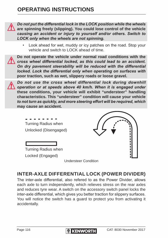
Page 116 CAT: 8030 November 2017
OPERATING INSTRUCTIONS
Do not put the differential lock in the LOCK position while the wheels are spinning freely (slipping). You could lose control of the vehicle causing an accident or injury to yourself and/or others. Switch to LOCK only when the wheels are not spinning.
• Look ahead for wet, muddy or icy patches on the road. Stop your vehicle and switch to LOCK ahead of time.
Do not operate the vehicle under normal road conditions with the cross wheel differential locked, as this could lead to an accident. On dry pavement steerability will be reduced with the differential locked. Lock the differential only when operating on surfaces with poor traction, such as wet, slippery roads or loose gravel.
Do not use the cross wheel differential lock during downhill operation or at speeds above 40 km/h. When it is engaged under these conditions, your vehicle will exhibit “understeer” handling characteristics. This “understeer” condition will cause your vehicle to not turn as quickly, and more steering effort will be required, which may cause an accident.
Turning Radius when
Unlocked (Disengaged)
Turning Radius when
Locked (Engaged)Understeer Condition
INTER-AXLE DIFFERENTIAL LOCK (POWER DIVIDER)The inter-axle differential, also refered to as the Power Divider, allows each axle to turn independently, which relieves stress on the rear axles and reduces tyre wear. A switch on the accessory switch panel locks the inter-axle differential, which gives you better traction for slippery surfaces. You will notice the switch has a guard to protect you from activating it accidentally.

CAT: 8030 November 2017 Page 117
OPERATING INSTRUCTIONS
INTER-AXLE DIFFERENTIAL LOCK OPERATION
To LOCK the inter-axle differential1. Anticipate when you might need increased traction, slow down to
a steady speed under 40 km/h or stop the vehicle. Do not lock the differential while going down steep grades or travelling faster than 40 km/h, or while wheels are spinning or traction is minimal. Lock the differential before you encounter these conditions.
2. Put the inter-axle differential lock switch in the LOCK position. A light in the warning cluster or on the air switch will turn on, indicating the differential is locked (engaged).
3. If you LOCK or UNLOCK the differential while moving, let up momentarily on the accelerator pedal to relieve torque on the gearing and allow full engagement of the clutch (mechanism that locks the wheels).
4. Drive the vehicle through the poor traction area, keeping your speed under 40 km/h.
The Meritor main differential lock or Dana wheel differential lock is controlled by the switch labelled INTER AXLE DIFF LOCK. By moving the switch, you can LOCK or UNLOCK the main differential when the vehicle is moving or stopped.
If your vehicle has an automatic transmission, it may be necessary to shift the transmission momentarily to the neutral position to allow the main differential lock splines to fully engage or disengage.
To UNLOCK the inter-axle differential1. When you reach normal road surfaces or better road conditions
where the differential lock is not needed, switch the differential lock to UNLOCK.
2. Let up momentarily on the accelerator pedal to relieve torque and allow the clutch to disengage.
3. When you unlock the differential, normal vehicle handling will resume and the light on the warning cluster or on the air switch will turn off.
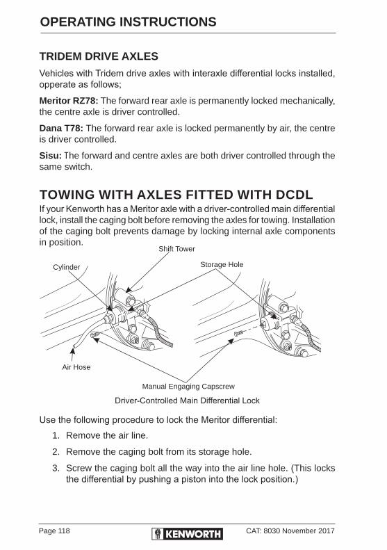
Page 118 CAT: 8030 November 2017
OPERATING INSTRUCTIONS
TRIDEM DRIVE AXLESVehicles with Tridem drive axles with interaxle differential locks installed, opperate as follows;
Meritor RZ78: The forward rear axle is permanently locked mechanically, the centre axle is driver controlled.
Dana T78: The forward rear axle is locked permanently by air, the centre is driver controlled.
Sisu: The forward and centre axles are both driver controlled through the same switch.
TOWING WITH AXLES FITTED WITH DCDLIf your Kenworth has a Meritor axle with a driver-controlled main differential lock, install the caging bolt before removing the axles for towing. Installation of the caging bolt prevents damage by locking internal axle components in position.
Driver-Controlled Main Differential Lock
Use the following procedure to lock the Meritor differential:1. Remove the air line.
2. Remove the caging bolt from its storage hole.
3. Screw the caging bolt all the way into the air line hole. (This locks the differential by pushing a piston into the lock position.)
Manual Engaging Capscrew
Storage HoleCylinder
Shift Tower
Air Hose
CAT: 8030 November 2017 Page 119
OPERATING INSTRUCTIONS
DUAL RANGE (TWO-SPEED) REAR AXLEYour vehicle may be equipped with a two-speed or dual range axle (option). You can select two rear axle ratios for operating under heavy loads or rough terrain as well as for over-the-road hauling.
The “Low Range” provides maximum torque for hauling heavy loads or travelling over rough terrain. The “High Range” is a faster ratio for highway speeds and over-the-road conditions. A switch on the accessory switch panel controls the dual range rear axle. You will notice the switch has a guard to protect from accidental activation. Always park your vehicle with the range selector in LOW.
DUAL RANGE AXLE OPERATIONFollowing are important tips on operating a Dual Range Axle with Interaxle Differential:
1. Shift the axle with the interaxle differential in the UNLOCKED position only.
2. When you are driving with poor traction, lock the differential. When you have the differential locked, drive with the axle in LOW range only.
3. When you are driving on a surface with good traction, keep the interaxle differential unlocked. You can drive with the axle in the LOW or HIGH range.
4. Always UNLOCK the interaxle differential before shifting the axle speed range.
If you shift the axle range with the interaxle differential in LOCK, you could seriously damage the axles. Never shift the axle range with the differential locked.
STARTING UP1. Unlock the interaxle differential before starting.
2. Put the Range Selector in the LOW range. Shift the transmission to start the vehicle moving.
3. When you are driving on rough terrain and secondary roads, or under a very heavy load, keep the axle in the LOW range. Shift the transmission to maintain proper road speed.
Page 120 CAT: 8030 November 2017
OPERATING INSTRUCTIONS
Never shift the axle when moving down hill. Engine driveline disengagement may occur, eliminating engine retardation and allowing the wheels to spin faster than the current speed of the engine. This may require severe braking to slow the vehicle down and can result in an accident.
Proper shifting of the axle depends on the synchronisation of engine/driveline and wheel speed. When you shift the axle, the connection between the engine and wheels is momentarily disengaged while the gearing is synchronised. Normally when the axle is shifted, the speed of the engine, axle and wheels adjust, allowing for proper gear engagement.
When the vehicle is going down hill, the wheels will not slow down, but will tend to speed up, which makes gear synchronisation almost impossible. As a result, the axle is neither in HIGH nor LOW range and all engine/driveline retardation is lost. Without engine retardation, it is difficult to slow the vehicle down and greater stress is put on the brake system.
To avoid damaging your vehicle, shift the axle at slower travel speeds until you are used to driving with a dual range axle.
LOW to HIGH (Cruising)When you go from rough terrain to highway driving, shift the axle to the HIGH range, following this procedure:
1. Be sure the differential is UNLOCKED.
2. Maintain your vehicle speed (accelerator depressed) and move the Range Selector lever to HIGH.
3. Keep driving with the accelerator depressed until you want the axle to shift.
4. To make the axle shift, release the accelerator until the axle shifts. You are now in the HIGH axle range for highway speeds. Shift the transmission normally to reach your desired cruising speed.

CAT: 8030 November 2017 Page 121
OPERATING INSTRUCTIONS
HIGH to LOW (Rough Terrain)If you need to downshift the axle for more power, or you are driving on rough terrain:
1. Maintain your vehicle speed (accelerator depressed) and move the Range Selector lever to LOW.
2. Keep driving with the accelerator depressed until you want the axle to downshift.
3. To make the axle downshift, release and depress the accelerator quickly to increase the engine rpm. The axle will shift to LOW range.
4. You are now in the LOW axle range for rough terrain and heavy loads. Shift the transmission normally to maintain the desired speed.
DRIVE AXLE TEMPERATURE GAUGEOptional Axle Temperature gauges may be installed in your Kenworth. Either a set of two gauges, one for each drive axle, or one for both forward and rear axles, indicate the lubricant temperature in each drive axle.
The temperatures indicated will vary with the kind of load you are carrying and the driving conditions you encounter. Very high temperatures signal a need to have the axle lubrication checked. Maximum axle temperature may vary, depending on the axle type and lubricant used.
For information on axle temperature ranges, see the Drive Axle Operation Manual.
Driving with very hot temperatures in the rear drive axles can cause serious damage to axle bearings and seals. Have the axle lubrication checked if you suspect overheating.

Page 122 CAT: 8030 November 2017
OPERATING INSTRUCTIONS
DRIVING TIPS AND TECHNIQUESThis section covers additional driving tips and techniques on how to drive your Kenworth more efficiently. It will give you information on starting, shifting and driving your Kenworth vehicle.
CoastingDo not coast with the transmission in neutral or with the clutch pedal depressed. It is a dangerous practice. Without the use of the retarding power of the drivetrain, your vehicle can reach dangerous speeds. At very high speeds you may not be able to put the transmission in any gear.
At high speeds, you could seriously damage your vehicle or cause an accident when you put the transmission in gear. The engine speed could exceed the maximum governed speed and cause a serious accident due to mechanical failures.
Besides being illegal and dangerous, coasting is also expensive. It causes premature failure of, or damage to, the clutch and transmission and overloads the brake system.
Coasting with the transmission in neutral also prevents proper transmission component lubrication. During coasting the transmission is driven by the rear wheels and the countershaft gear (which lubricates the transmission components by oil splash) will only be turning at idle speed.
Descending a GradeDo not hold the brake pedal down too long or too often while going down a steep or long grade. This could cause the brakes to overheat and reduce their effectiveness. As a result, the vehicle will not slow down at the usual rate.
To reduce the risk of personal injury and/or an accident, before going down a steep or long grade, reduce speed and shift the transmission into a lower gear to help control your vehicle speed. Failure to follow procedures for proper downhill operation could result in loss of vehicle control.

CAT: 8030 November 2017 Page 123
OPERATING INSTRUCTIONS
Climbing and DescendingWhen approaching an uphill grade, apply light throttle early to build up engine temperature gradually, so that when power is applied for the climb, the engine won’t be subjected to a sudden, large heat change. Use the tachometer and pyrometer to maintain optimum power/temperature relationship during the climb.
As you approach the top of the grade, begin easing up on the throttle to allow engine temperature to dissipate gradually. This technique can be a real engine-saver when cresting a hill just prior to beginning a descent down the other side. Running uphill at full throttle, then quickly coming off the throttle entirely as the descent begins, puts punishing stresses on the engine.
Downhill GradesGear selection is critical when descending hills. Engine overspeed can occur when using the engine as a brake because the engine governor does not function as a brake. A rule-of-thumb for gear selection is to go down a hill in the same gear used to climb it.
If engine rpm approaches the top limit, apply brakes or shift up to a higher gear. Use regular moderate brake application to bring speed to about 10 km below desired speed, and release the brakes to allow the truck to speed up again.
This procedure allows all brakes to contribute to brake performance, whereas a light continuous application can cause one axle to do all the braking.
Mountain DrivingApproaching an uphill grade, apply throttle to build up engine temperature gradually and be in the best power range for the climb. As you approach the summit, shift down one or two gears to allow the engine to cool down slowly, especially if you are going to descend on the other side.
Level CruisingIf the pyrometer indicates excessive temperature while cruising, ease off slightly on the throttle. Normally, on a smooth, level road, there should be no loss of rpm and speed, and the pyrometer should indicate a drop in temperature. If rpm and speed begin to drop, and the temperature remains high, shift down one step to maintain speed and allow the temperature to stabilise. Conversely, if the pyrometer indicates consistently low temperature, then shift up one step and monitor the pyrometer.

Page 124 CAT: 8030 November 2017
OPERATING INSTRUCTIONS
Establishing Optimum Operating Temperatures• Climb an uphill grade at maximum operating rpm and full throttle for
one minute. Record the pyrometer reading at the end of this time interval, then ease up on the throttle.
• Subtract 110°C from the recorded temperature reading. This is your maximum (and optimum) operating temperature.
Use the above method if there is no label on the pyrometer specifying the maximum temperature, and as an occasional check on engine condition. Any large variation in the maximum temperature reading may be an early indication of possible engine trouble.
Different size injectors, or changes in altitude, may affect engine operating temperatures. Turning off the engine while there are high pyrometer temperatures may damage turbo bearings.
AcceleratingThe practice of rapidly accelerating a loaded vehicle from a standstill can cause severe damage to the drive shaft, transmission and rear axle.
Normal service life of these components can be greatly extended by gradual and smooth acceleration.
If the driver were to unnecessarily accelerate a fully loaded vehicle with full throttle in the lower gears, the resulting propeller shaft and axle shaft torques would be tremendous. This would certainly cause greatly reduced service life, if not immediate damage.
It is possible to start any legal load smoothly without creating excessive strain on the driveline components. ALWAYS ACCELERATE THE VEHICLE GRADUALLY AND SMOOTHLY, especially when in lower gears.
Engine Crankshaft Torque1,224 Nm.
Propeller Shaft Torque9,729 Nm.
Axle Shaft Torque36,720 Nm.

CAT: 8030 November 2017 Page 125
OPERATING INSTRUCTIONS
City Driving — Cruising Operate the engine in the preferred rpm range to obtain optimum performance, and reduce stresses and wear. Avoid lugging the engine for any extended period of time as this reduces engine life. Consult your engine manufacturer’s operation manual for the preferred operating range.
Observe the tachometer and operate the engine within its economical rpm range, with a minimum of gear shifting. It is not necessary to keep the engine revving in its high rpm range.
Cruise at partial throttle whenever conditions permit. When approaching an uphill grade, smoothly apply full throttle so that the climb will be started at full power. Downshift as necessary to maintain vehicle speed without lugging the engine.
For your particular engine and operating conditions refer to the engine manufacturer’s operating manual.
INSTRUCTIONS TO PREVENT JACKKNIFINGMost truck and semi-trailer jackknifes occur when the roads are wet and the semi-trailer is unladen.
This is because the drive tyres will skid much more easily when there is water between the tread and the road surface.
Also, when the semi-trailer is unladen (50% of the time with tankers and tippers), there is less weight on the drive tyres so less brake pedal travel is required to lock the brakes.Awareness that wet weather and empty load combination is the most dangerous condition will be sufficient for good drivers to avoid jackknifing.However, there are also several other factors which should concern drivers and operators since they also influence brake balance and tyre adhesion and hence the possibility of jackknife. The following is a list of these items:
1. Tyre tread pattern must be adequate to remove water under wet conditions. This is particularly important on drive tyres. Rib tread patterns are substantially better than lug type.
2. Tyre tread depth must be sufficient to get water out from under most of the tyre contact patch (3 mm is the minimum tread depth for truck tyres).

Page 126 CAT: 8030 November 2017
OPERATING INSTRUCTIONS
3. Jacobs or other auxiliary brake systems should never be used simultaneously with the foot brake. To do so unbalances the brakes and can cause the drive wheels to skid, resulting in a jackknife.
Operating the auxiliary brakes when the semi is unladen during wet weather should be prohibited because, in an emergency, the driver will instinctively apply the service brakes and possibly skid the drive wheels, which can cause a jackknife.
4. Use of the trailer control valve incorporating a brake ratio valve should be strictly controlled. If this valve is in setting 0, 1 or 2, then brake capability is transferred from trailer to truck drive axles. This means that brakes are unbalanced and, particularly when the combination is unladen, drive axle lock-up and jackknifing can occur.
5. Brakes should be balanced, i.e brake force generated must be in direct proportion to the load carried on the axle being braked. For this to occur:
• Brakes should be same type and size.
• Linings should all be the same material.
• Pipe lengths, sizes and connections should be appropriate to allow all brakes to apply as near as possible to simultaneously.
6. Semi-trailer suspension roll stiffness should be equal to, or greater than, that of the truck to minimise degradation of brake balance by minimising side-to-side weight transfer when cornering.
7. Semi-tankers should never be operated with less load on each individual drive axle than on each individual semi-tanker axle, i.e. if the semi-tanker combination is to be driven with some tanks empty, the middle compartment should be emptied first, then the rear and lastly the compartment over the drive axles.
The combination should not be operated with the compartment over the drive axles empty and other compartments full.
Typically, an unladen semi-tanker or tipper will skid on wet roads and possibly jackknife at 10%-15% of normal brake pedal movement. Drivers must be aware of this and must drive at least 2 or 3 times the normal distance behind the vehicle in front under these conditions.

CAT: 8030 November 2017 Page 127
OPERATING INSTRUCTIONS
ECONOMICAL DRIVINGThe following section includes recommendations for best engine performance and economy.
Engine Overspeed - RPM• Operate the engine within the optimum engine rpm range and do
not allow the rpm to exceed the maximum governed speed. See your Engine Operation and Maintenance Manual for information regarding engine rpm.
• When the engine is used as a brake to control vehicle speed (e.g. while driving down a grade), do not allow the engine rpm to exceed maximum governed speed.
• Under normal load and road conditions operate the engine in the lower end of the range.
To avoid engine damage, do not let the engine rpm go beyond the maximum governed rpm. Valve damage could result if overspeed conditions occur.
Often these recommendations are secondary to maintaining an adequate and safe speed relative to the surrounding traffic and road conditions.
Use of TachourmeterThe tachourmeter is an instrument that helps you obtain the best performance of the engine and manual transmission, serving as a guide for shifting gears. Refer to the Engine Operation and Maintenance Manual for optimum engine rpm.
• If the engine rpm moves beyond the maximum governed speed, indicating an overspeed condition, apply the service brake or shift to a higher gear to bring engine rpm within the optimum speed range.
• When driving downhill, shift to a lower gear, use the engine brake (if so equipped), and use the service brake, keeping the engine speed below 2100 rpm.
When the engine speed reaches its maximum governed speed, the injection pump governor cuts off fuel to the engine. However, the governor has no control over the engine rpm when it is being driven by the vehicle’s transmission, for example, on steep downgrades. Apply service brakes or shift to a higher gear.

Page 128 CAT: 8030 November 2017
OPERATING INSTRUCTIONS
Fuel economy and engine performance is also directly related to driving habits:
• The best results in trip time and fuel economy are obtained while driving the vehicle at a steady speed.
• Shift into higher or lower gears (or apply the service brake) to keep engine rpm near the lower end of the optimum operating range.
• Avoid rapid acceleration and braking.
Fuel - Excessive ConsumptionThe vehicle’s fuel consumption is connected to three important factors: maintenance, driving habits, and general condition of the road (including traffic conditions and vehicle load).
Maintenance factors affecting fuel consumptionProper maintenance will keep the vehicle running like new even after long periods of use. The driver must perform daily and weekly checks of the vehicle for:
• Engine valves out of adjustment.
• Injection pump improperly synchronised.
• Injection nozzles defective or uncalibrated.
• Improperly inflated tyres.
• Wheel bearings improperly adjusted.
• Dragging brakes.
• Clutch improperly adjusted or worn (slipping).
• Fuel leaks.
• Clogged up Charge Air Cooler.

CAT: 8030 November 2017 Page 129
OPERATING INSTRUCTIONS
Driving HabitsWrong driving habits must be corrected and the recommendations on economic driving should be followed.
Driving factors affecting fuel consumption:• Excessive speed and unnecessary fast acceleration.
• Long periods of idling.
• Driving with foot rest ing on the clutch pedal (manual transmission).
General ConditionsOther factors affecting fuel consumption are related to loads and the type of roads on which the vehicle operates. It is not always possible to choose the best road, but it must be kept in mind that the ideal road is the one that allows a steady speed in high gear, without requiring frequent braking and acceleration.
The following general conditions can affect fuel consumption:• Overload.
• Unbalanced load.
• Very high load.
• Poorly maintained roads.
• Traffic conditions.
SAFE DRIVINGThe following recommendations are merely informative and do not cover all safety precautions. Safe driving is, above all, the responsibility of the driver.
The safe operation of a vehicle is not just following the established traffic rules, but should also include maintaining the vehicle in good mechanical condition and proper operation of the engine, transmission and brakes.
Page 130 CAT: 8030 November 2017
OPERATING INSTRUCTIONS
The following guidelines will help you to drive the vehicle safely:• Make a thorough inspection of the vehicle, daily and weekly. See
Driver’s Checklist, page 21.
• Ensure windows, mirrors and lights are clean.
• Check all tyres for damage and correct inflation pressure.
• Adjust the seat to a comfortable driving position for easy access to pedals and vehicle controls.
• Adjust rear-view mirrors.
• Always use safety belts.
• Do not exceed the GVM/GCM.
• Proportionally distribute loads on the frame.
• Always keep the brakes adjusted and in proper condition. See Checks and Adjustments on page 156.
• Obey speed limits and all traffic signals.
• When driving downhill, select the same gear used to climb the hill. Use the brakes properly - do not ride them.
• Do not exceed maximum governed speed (as specified in the Engine Operation and Maintenance Manual).
Do not exceed the specified load rating. Overloading can result in loss of vehicle control and personal injury, either by causing component failures or by affecting vehicle handling. Exceeding load ratings can also shorten the service life of the vehicle.
The components of your vehicle are designed to provide satisfactory service if the vehicle is not loaded in excess of either the gross combined weight rating (GCM), or the maximum front and rear gross axle weight ratings (GVMs) (axle weight ratings are listed on the passenger’s seat base).
For your safety and the safety of others, follow routine and periodic maintenance schedules for all components on your vehicle. See Maintenance and Lubrication Schedule, pages 239 - 264.

CAT: 8030 November 2017 Page 131
OPERATING INSTRUCTIONS
AIR SUSPENSIONAir Suspension Height/Air PressureYour vehicle may have an air suspension and a deflation switch which allows the air in the suspension to be exhausted using a switch on the dash. The normal purpose of this feature is to allow you to lower the vehicle for loading. On prime movers, the deflate switch allows you to lower the fifth wheel to slide under a trailer. A guard on the switch prevents you from accidentally deflating the suspension.Do not operate the Air Suspension Deflate Switch (Dump Valve) while driving. Sudden deflation while your vehicle is moving can affect handling and control and could lead to an accident. Use this switch only when your vehicle is not moving.
Operating a vehicle with air suspension bags either overinflated or underinflated may cause damage to driveline components. If a vehicle must be operated under such conditions, do not exceed 8 km/h.
Driving with Deflated Air SpringsIf an air spring ruptures, there will be enough air pressure to drive the vehicle to a safe stop off the highway to investigate the problem.Do not drive with ruptured air springs. The air loss can cause the spring brakes to apply. This allows your brakes to drag and may burn up the linings, which could lead to an injury or accident. Do not continue to operate the vehicle in this condition.
Do not tamper with the height adjustment valve on your Airglide rear suspension. The height is factory-set for optimum performance. Consult an authorised Kenworth dealer if the ride height requires adjustment.
Suspension Air Pressure GaugeThe Suspension Air Pressure gauge (optional) indicates the amount of air pressure in the air suspension springs in kilopascals (kPa). Air pressure in the spring is related to the rear axle load. The greater the rear axle load, the greater the air pressure in the air bags. Therefore, the air pressure displayed will vary, depending on the rear axle load.

Page 132 CAT: 8030 November 2017
OPERATING INSTRUCTIONS
FIFTH WHEELThe following applies to prime mover configurations:Ensure that all fifth wheel maintenance, adjustments and rebuilding are done only by a qualified mechanic. An improperly maintained fifth wheel can cause a trailer to separate from a truck. This could lead to an injury or accident and damage to property.
FIFTH WHEEL JAW LOCK
To unlock the fifth wheel lockPull out on the lever (usually located on the right-hand side of the fifth wheel) until it remains in an overcentre position.
HOOK-UPAfter connecting your truck to the trailer, always inspect the jaws to be sure they have locked on the kingpin before you drive the vehicle.
AIR ACTIVATED 5TH WHEEL RELEASE PROCEDURE
Jost 5th Wheels
1. Apply Park Brake
2. Switch the 5th Wheel rocker air switch to the UNLOCK position
3. Warning light on rocker air switch and 5th Wheel Release Red lamp on dash light illuminates
4. Push and hold for at least 1 second, the 5th wheel release warning lamp on dash to release the 5th wheel
5. Switch the 5th wheel rocker air switch to the LOCK position when the trailer has been released
6. All 5th wheel warning lights must be OFF
5TH
WHEEL
UNLOCK
LOCK
5TH WHEEL
RELEASE
Release Warning Lamp
Rocker Air Switch
CAT: 8030 November 2017 Page 133
OPERATING INSTRUCTIONS
FIFTH WHEEL LUBRICATIONFrequently operate and lubricate movable or sliding fifth wheels to prevent corrosion.
Both the fifth wheel plate and the slide tracks (if a slider) should be cleaned and lubricated periodically to ensure smooth turning and sliding action. Failure to keep these surfaces lubricated can lead to frame and/or driveline damage.
Apply a water-resistant lithium base grease to the trailer contact surface of the fifth wheel. Apply same to the bearing surface of the support bracket through the grease fittings on the side of the fifth wheel plate. The plate must be lifted up slightly to relieve weight on the bracket while applying grease.
Where fitted, do not grease Teflon fifth wheel wear plates.
TOW HITCHYour vehicle may be fitted with a tow hitch. This is only designed to be used in an emergency. The tow hitch is only designed to tow an unladen prime mover.
DO NOT ATTEMPT TO TOW A FULLY LADEN VEHICLE USING A TOW HITCH. The tow hitch could snap causing damage to either or both vehicles, resulting in an accident or injury to yourself and/or others plus property damage.
TOWINGAll lubricating and transmission application oil pressure is provided by an engine-driven pump. This pump cannot be “motored” by pushing or towing the vehicle when the engine is stopped. Whenever the vehicle must be towed, the driveline must be disconnected or the driving wheels must be lifted off the ground.To prevent transmission damage when towing a truck, disconnect the driveshaft at the rear U-joint.Transmission damage occurs rapidly when towing with the driveshaft connected because the transmission countershaft is stationary and no lubricant reaches the mainshaft gears and bearings.
Worse, when vehicles are towed at an angle from the front, either by wrecker or piggy-back, the lubricant usually in the top front of a drive axle will drain to the rear, leaving these top components dry.

Page 134 CAT: 8030 November 2017
OPERATING INSTRUCTIONS
RETURNING VEHICLE TO SERVICEYour vehicle may have lost lubricant while being towed. To prevent damage, check the oil level and add oil if necessary.
After adding the specified type and amount of lubricant, drive the vehicle. It should be unloaded. Drive 1.5 to 3 km at a speed not exceeding 40 km/h. This will thoroughly circulate the lubricant through the assembly.
VEHICLE RECOVERY AND SPRING BRAKESIf your vehicle must be recovered, disconnect the driveline at the rear U-joint, and remove or support the rearmost section of the driveline. This is necessary because if the transmission is driven by the driveshaft (rear wheels on the ground), no lubricant will reach the gears and bearings, causing damage to the transmission.
Remove the driveline and axle shafts or lift the driving wheels off the ground before towing the vehicle. See Driver Controlled Main Differential Lock page 115.All lubricating and transmission application oil pressure is provided by an engine-driven pump, which will not work when the engine is stopped. You could seriously damage your vehicle by towing it with the driveline connected and the drive wheels on the ground.
Worse, when vehicles are towed, either by wrecker or piggyback, the lubricant in the top front of the drive axle will drain to the rear. This will leave the top components dry. The resulting friction may seriously damage them. Always remove the main driveshaft and axle shafts before towing your vehicle.

CAT: 8030 November 2017 Page 135
OPERATING INSTRUCTIONS
SPRING BRAKES - MANUAL RELEASEIn order to tow a vehicle, if there is insufficient air to release the parking brake, the spring brakes can be manually released.
Do not drive a vehicle with malfunctioning brakes. If one of the brake circuits should become inoperative, braking distances will increase substantially and handling characteristics while braking will be affected. You could lose control of your vehicle, be severely injured, or cause an accident. Have it towed to the nearest dealer or qualified workshop for repair.You may sometimes have to release your vehicle’s spring brakes by hand. This could happen if the system air pressure does not reach operating pressure because your engine or compressor is not working properly. You will have to release the spring brakes at the spring brake chambers.
Do not disassemble a spring brake chamber. These chambers contain a powerful spring that is compressed. Sudden release of this spring can cause severe injury.
Do not operate a vehicle when the spring brakes have been manually released. Driving a vehicle after its spring brakes are manually released is extremely dangerous. You will probably have no brakes at all. You could have a serious or fatal accident.
Releasing the spring brakes on an unsecured vehicle could lead to an accident. The vehicle could roll, causing severe injury. Always secure the vehicle with wheel chocks, chains, or other safe means to prevent rolling before manually releasing the spring brakes.When the vehicle has finished being towed, manually lock the spring brakes, returning the brakes back to their normal operating condition. This is a reversal of the release procedure, see steps 1-6 on page 136.
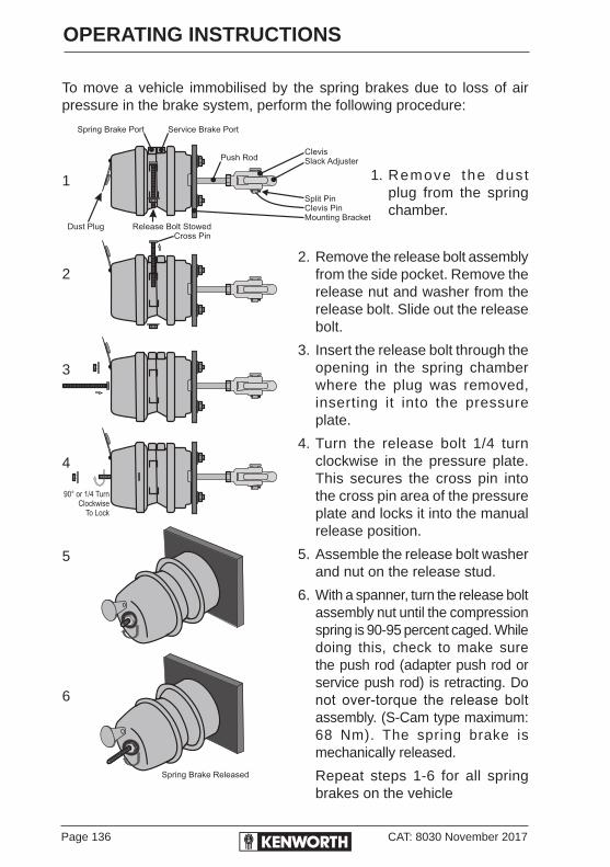
Page 136 CAT: 8030 November 2017
OPERATING INSTRUCTIONS
To move a vehicle immobilised by the spring brakes due to loss of air pressure in the brake system, perform the following procedure:
1. Remove the dust plug from the spring chamber.
2. Remove the release bolt assembly from the side pocket. Remove the release nut and washer from the release bolt. Slide out the release bolt.
3. Insert the release bolt through the opening in the spring chamber where the plug was removed, inserting it into the pressure plate.
4. Turn the release bolt 1/4 turn clockwise in the pressure plate. This secures the cross pin into the cross pin area of the pressure plate and locks it into the manual release position.
5. Assemble the release bolt washer and nut on the release stud.
6. With a spanner, turn the release bolt assembly nut until the compression spring is 90-95 percent caged. While doing this, check to make sure the push rod (adapter push rod or service push rod) is retracting. Do not over-torque the release bolt assembly. (S-Cam type maximum: 68 Nm). The spring brake is mechanically released.
Repeat steps 1-6 for all spring brakes on the vehicle
1
2
3
4
5
6
CAT: 8030 November 2017 Page 137
OPERATING INSTRUCTIONS
Freeing the Vehicle from Sand, Mud or IceIf the vehicle gets stuck in sand, mud or ice:
• Move the gearshift lever or selector from First to Reverse.
• Apply light pressure on the accelerator pedal while the transmission is in gear.
• Remove your foot from the accelerator while shifting.
• Do not race the engine.
• For best traction and safety, avoid spinning the wheels.Do not spin the wheels faster than 55 km/h. Spinning a tyre at speedometer readings above this can be dangerous. Tyres can explode from spinning too fast. Under some conditions, a tyre may be spinning at a speed twice that shown on the speedometer. Any resulting tyre explosion could cause severe injury or death to a bystander or passenger, as well as extensive vehicle damage, including tyre, transmission and/or rear axle malfunction.
Comply with the following instructions to avoid transmission damage:
• Always start vehicle in motion with the shift lever in first gear.
• Be sure transmission is fully engaged in gear before releasing the clutch pedal (manual only).
• Do not shift into reverse while the vehicle is moving.
• Do not permit the vehicle to be towed for long distances without removing the driveshaft.

Page 138 CAT: 8030 November 2017
OPERATING INSTRUCTIONS
SHUT-DOWNAfter you have parked in a safe place, check your vehicle to make sure it will be ready for the next trip. To make sure your vehicle is ready to go after a long stop (such as overnight), please follow the suggestions below. Your vehicle will be easier to get going when you are ready, and it will be safer for everyone who might be around it.
BEFORE STOPPING THE ENGINEDo not shut off the engine immediately. A hot engine stores a great amount of heat and it does not cool down immediately after you shut if off. Always cool the engine down before shutting it off. You will greatly increase its service life.
Idle the engine at 1,000 rpm for five minutes. Then low idle for thirty seconds before shutdown. This will allow circulating coolant and lubricating oil to carry away heat from the cylinder head, valves, pistons, cylinder liners, turbocharger and bearings. This way you can prevent engine damage that may result from uneven cooling.
TURBOCHARGERThis cooling-down practice is especially important for a turbocharged engine. The turbocharger on your vehicle contains bearings and seals that are subjected to hot exhaust gases. While the engine is operating, heat is carried away by circulating oil. If you stop the engine suddenly after a hard run, the temperature of the turbocharger could rise to as much as 540°C above the temperature reached during operation. A sudden rise in temperature like this could cause the bearings to seize or the oil seals to loosen.
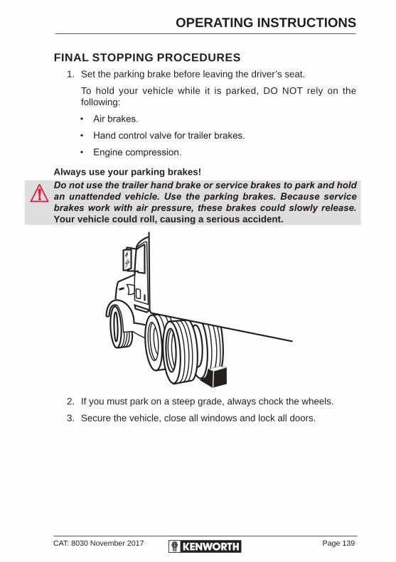
CAT: 8030 November 2017 Page 139
OPERATING INSTRUCTIONS
FINAL STOPPING PROCEDURES1. Set the parking brake before leaving the driver’s seat.
To hold your vehicle while it is parked, DO NOT rely on the following:
• Air brakes.
• Hand control valve for trailer brakes.
• Engine compression.
Always use your parking brakes!Do not use the trailer hand brake or service brakes to park and hold an unattended vehicle. Use the parking brakes. Because service brakes work with air pressure, these brakes could slowly release. Your vehicle could roll, causing a serious accident.
2. If you must park on a steep grade, always chock the wheels.
3. Secure the vehicle, close all windows and lock all doors.

Page 140 CAT: 8030 November 2017
OPERATING INSTRUCTIONS
REFUELLINGAir inside the fuel tanks allows water to condense in the tank. To prevent this condensation while the vehicle is parked for extended periods, do not overfill the tanks above 95 percent of capacity.
95 percent is to the lower edge of the filler neck so that air gap is still visible, as this provides room for expansion resulting from temperature extremes. When refuelling, add approximately the same amount to each fuel tank on vehicles with more than one tank.
Do not carry additional fuel containers in your vehicle. Fuel containers, either full or empty, may leak or explode and cause or feed a fire.Diesel fuel in the presence of an ignition source (such as a cigarette) could cause an explosion. You could be seriously injured. A mixture of gasoline or alcohol with diesel fuel increases this risk of explosion.
Never refuel while engine is idling. Shut down a vehicle before refuelling, this can allow air to enter the fuel system resulting in a possible shutdown.
• Do not remove a fuel tank cap near an open flame.
• Use only the fuel and/or additives recommended for your engine.
FUEL SPECIFICATIONUse only diesel fuel, as recommended by engine manufacturers. If you need further information on fuel specifications, consult the Engine Operation and Maintenance Manual.
LOCATION OF FUEL SHUT-OFF VALVESFuel shut-off valves for the fuel crossover line are on the bottom of the fuel tank(s), at the crossover line connection.
Filler Cap
Air Gap
Air GapFiller Neck
Round fuel tank - Maximum fill level = 95%
Square fuel tank - Maximum fill level = 95%
Filler Cap
Filler Neck

SECTION TWOPREVENTIVE MAINTENANCE

CAT: 8030 November 2017 Page 143
PREVENTIVE MAINTENANCE
INTRODUCTIONThis section will help you keep your Kenworth in good running condition. There are a number of checks you can do, and you may be able to do some of the service work yourself. But please, let your authorised Kenworth dealer do any work you do not have the tools or skill to perform. Authorised service mechanics are trained in the proper technical and safety procedures to maintain your Kenworth correctly.
Good driving practices, daily and weekly driver maintenance inspections, and periodic service inspections by an authorised Kenworth dealer, will help keep your Kenworth in good working order and provide many years of dependable service.
It is dangerous to work on a vehicle without the right know-how and proper tools. People could be seriously injured, damage can be done to the vehicle, or your vehicle could become unsafe to drive. Perform only work you know you are fully able to do, and for which you have the right tools.
ENVIRONMENTAL PROTECTIONAND MATERIAL HAZARDS
Some of the ingredients in engine oil, hydraulic oil, transmission and axle oil, engine coolant, diesel fuel, airconditioning refrigerant (R-134a and PAG oil), batteries, etc., may contaminate the environment if spilled or not disposed of properly. Non-compliance with environmental regulations can result in fines and/or jail terms. Contact your local government agency for information concerning proper disposal.
Page 144 CAT: 8030 November 2017
PREVENTIVE MAINTENANCE
SAFETY PRECAUTIONS• Before attempting any procedures in the engine compartment, stop
the engine and let it cool down. Hot components can burn skin on contact.
• Be alert and cautious around the engine at all times while it is running.
• If work has to be done with the engine running, always (1) set the parking brake, (2) chock the wheels, and (3) ensure the shift lever or selector is in neutral.
• Exercise extreme caution to prevent neckties, jewelry, long hair, or loose clothing from getting caught in the fan blades or any other moving engine parts.
• Always support the vehicle with appropriate safety stands if it is necessary to work underneath the vehicle. A jack is not adequate for this purpose.
• Disconnect the battery ground strap whenever you work on the fuel system or the electrical system. When you work around fuel, do not smoke or work near heaters or other fire hazards. Keep an approved fire extinguisher handy.
• When working underneath the vehicle without appropriate safety stands but with the wheels on the ground (not supported), make sure that (1) the vehicle is on hard level ground, (2) the parking brake is applied, (3) all wheels are chocked (front and rear) and (4) the engine cannot be started. Remove the ignition key.
• Never start or let the engine run in an enclosed, unventilated area. Exhaust fumes from the engine contain carbon monoxide, a colourless and odourless gas. Carbon monoxide can be fatal if inhaled.
Incomplete or improper servicing may cause problems in the operation of the vehicle. If in doubt about any servicing, have it done by an authorised Kenworth service dealer. Improper maintenance during the warranty period may also affect warranty coverage.Modifying your vehicle can make it unsafe. Some modifications can affect your vehicle’s electrical system, stability, or other important functions. Before modifying your vehicle, check with your Kenworth dealer to make sure it can be done safely and correctly.
CAT: 8030 November 2017 Page 145
PREVENTIVE MAINTENANCE
LUBRICATION SPECIFICATIONS - ENGINEYou will find a complete Engine Lubrication Service Guide in the Engine Operation and Maintenance Manual. There, the engine manufacturer explains more fully all the maintenance operations you and a qualified service mechanic will need.
Please remember, one key to keeping your Kenworth running at top economy and to prolonging its life, is proper lubrication and servicing. Neglecting this essential aspect of vehicle care can cost time and money in the long run.
In the following section, you will find basic information needed to perform routine vehicle lubrication. Of course you will want to schedule service more frequently if you are operating under severe conditions such as extreme heat or cold, very heavy loads, off-road, etc.Do not mix different types of lubricants. Mixing lubricants (oil and grease) of different brands or types could damage vehicle components. Therefore, drain (or remove) old lubricants from the unit before refilling it. Handle lubricants carefully. Vehicle lubricants (oil and grease) can be poisonous and cause sickness. They can also damage the paint on the vehicle.
For any special service requirements, consult your service manuals and your lubricant supplier. The component manufacturer’s specification and requirements take precedence over other specifications.When switching between types of lubricants, thoroughly drain all areas of the component.
Lubricating SystemCheck oil lines, housing and connections for leaks, damage or deterioration. Leaks could be the result of damaged oil lines or seals.
Service IntervalsCheck engine oil daily.
Oil DrainingRefer to the engine manufacturer’s Engine Operation and Maintenance Manual supplied with your vehicle for information about draining and refilling engine oil, engine crankcase capacity, engine oil type and changing oil filters etc.Hot engine oil can be dangerous. You could be seriously burned. Let the engine oil cool down before changing the oil.

Page 146 CAT: 8030 November 2017
PREVENTIVE MAINTENANCE
• Drain the oil into a container designed for this purpose.
• When draining the oil, remove the plug with the proper size spanner and keep as far away as possible. Always keep your forearm parallel to the ground to help prevent hot oil from running down your arm.
• The oil filler cap must be secured to avoid an oil spill causing a potential fire hazard.
Oil Level CheckTo check the engine oil level, park the vehicle on level ground and wait 5 minutes after shutting the engine down. This allows time for the oil to drain back to the oil pan.
Remove the dipstick and wipe it off with a clean, lint-free rag. Reinsert the dipstick all the way in and pull it out again to check oil level. Correct oil level is between the low (L) and high (H) marks on the dipstick.
For further information regarding oil level, see the engine manufacturer’s Engine Operation and Maintenance Manual supplied with the vehicle.
Oil ReservoirsFor oil reservoirs with side filler plugs (transmissions, axles, steering gear boxes, transfer cases etc.) the oil must be level with the filler opening. Hub reduction axles may require specific oil volumes to ensure correct levels. (Refer to Electronic Customised Maintenance Manual, rear axle section.)
Use care when checking the oil level with your finger. Just because you can reach the oil level with a finger, does not mean the oil level is correct.Oil Sampling
Analysis of your major components oil is crucial in keeping your truck running smoothly. The health of your engine, gearbox/automatic transmission and drive axles is often identified by the quality and condition of your lubricating oils. All authorised PACCAR dealerships can carry out oil sampling of your vehicle.
Oil sampling can be divided into three categories:
• analysis of oil properties including those of the base oil and its additives
• analysis of contaminants• analysis of component wear
Your PACCAR dealer can supply a test kit (Part No DFOSK) to provide a sample of oil for testing.
CAT: 8030 November 2017 Page 147
PREVENTIVE MAINTENANCE
FUEL SYSTEM
FUEL SPECIFICATIONSUse only premium quality diesel fuel as recommended by engine manufacturers. Consult your Engine Operation Manual if information on fuel specifications is required.
To prevent condensation while the vehicle is parked for extended periods, do not overfill the tanks above 95 percent of capacity, 95% is to the lower edge of the filler neck so that air gap is clearly visible, as this provides room for expansion resulting from temperature extremes (see page 140).
FUEL FILTERSFollow these recommendations when changing fuel filters or strainer elements:
1. Cover any electrical equipment and wiring that might get soaked with fuel when removing filters. Diesel fuel can permanently damage electrical insulation.
2. When installing spin-on (throwaway) filters, hand-tighten only, to the recommended 1/2 to 2/3 turn after gasket contact. Mechanical tightening can distort or crack the filter head.
3. When replacing a filter element, use no substitutes. Only filter elements designed for fuel filtration should be used. After cleaning and inspecting the shell, insert the new element and fill the container at least 2/3 full of clean fuel before installing the shell. Density-type strainer elements should be soaked in clean fuel before installing to expel all air.
4. Discard old gaskets and replace with new ones to ensure a positive seal.
5. With shell and gasket properly positioned, tighten the cover nut or bolt just enough to prevent fuel leakage.
6. After starting the engine, check for any leaks around the filter.
Page 148 CAT: 8030 November 2017
PREVENTIVE MAINTENANCE
Filter Draining1. Check fuel filter/water separator daily. Check with engine OFF.
Depending on the fuel storage facility, more frequent draining may be required.
2. Open drain valve (by hand only) and turn valve screw counter clockwise approximately 1½ to 2 turns until draining occurs. Drain filter sump of water until clear fuel is visible.
3. If entrapped water exceeds sump volume, you can either:
a. Close valve and run engine until smooth idle is established, then repeat drain procedures.
b. Remove filter from mounting head, completely drain all fluid and reassemble filter assembly. Be sure to follow new filter assembly instructions.
4. Close drain valve by turning valve screw clockwise approximately 11/2 to 2 turns. Do not overtighten the valve.
Overtightening can damage the threads.
WHEN DUAL FUEL TANK PICK-UPS AND RETURNS ARE FITTEDMaintain adequate fuel in both pick-up tanks when using tank isolating valves.
FUEL TANK STRAP TENSIONT-Strap tension for strap with anti-roll wedge: 46 - 49 lb ft (62 - 66 Nm) (or rear-most strap with no wedge fitted on each tank)Rectangular fuel tank strap tension: 20 - 30 lb ft (27 - 41 Nm)
All other straps to reduced tension: 8 - 12 lb ft (11 - 16 Nm)
CAT: 8030 November 2017 Page 149
PREVENTIVE MAINTENANCE
AIR CLEANER SYSTEMS
AIR CLEANERS AND FILTER REPLACEMENTComplete disassembly and cleaning is recommended at each 40,000 km service interval. Under severe operating conditions, this should be done more frequently. Damaged or defective parts should (with the possible exception of mounting brackets) be replaced, not patched or repaired.
The following service information is basic to all air cleaner makes and models:
• Filter elements should be serviced when the air cleaner restriction indicator locks in the high position or when the air cleaner restriction gauge (optional) reads 25 inches H2O or higher. If your vehicle is equipped with a dry-type air cleaner, have the element serviced at an authorised Kenworth dealer.
• Paper elements require care and proper handling, because they are critical to engine service life.
• Service the air cleaner periodically. If the vehicle operates in areas with heavy dust, maintenance should be more frequent.
• Air cleaners should be replaced when service indicator pops.
AIR INTAKE SYSTEMEngine heat, vibration and age combine to loosen air intake connections and cause cracks in the tubing and elbows. Leaks in the intake system allow abrasive dust to enter the engine and quickly cause expensive damage. During your daily walk-around inspection, carefully check all tubing, elbows, clamps supports and fasteners for condition and tightness.
• Under normal operating conditions, Kenworth recommends complete disassembly and cleaning of the air intake system at each 40,000 km service. Under severe operating conditions, the disassembly and cleaning should be more frequent. Replace any defective parts. With the possible exception of mounting brackets, do not repair defective parts.
• Check the Charge Air Cooler for air leaks annually. The air leaks can be caused by cracked tubes or header. For service, see your authorised Kenworth dealer.

Page 150 CAT: 8030 November 2017
PREVENTIVE MAINTENANCE
ACCESSORY DRIVE BELTSThe reliability and service life of drive belts can be extended with proper attention to installation, adjustment and maintenance. Neglect in these matters could cause belt failure, resulting in potential hazards through loss of the electrical or air system and possible engine damage due to overheating.
INSTALLATION1. Loosen pulley bracket(s) and shorten the distance between pulley
centres. lnstall the new belt without forcing it. Do not roll or lever the belt over the pulley.
2. Where twin belts are used, these must be fitted as a matched pair.
3. Check pulley alignment and adjust if necessary. Pulley mis-alignment must not exceed 1.5 mm for each 300 mm of free-span. Belt free-span is measured between pulley centres.
4. Check the riding depth. Belt riding depth should not vary more than 1.5 mm on matched belt sets.
5. Check the belt does not ride on the bottom of the pulley groove, and that the outside edge of the belt does not protrude more than 1.5 mm beyond the outside edge of the pulley.

CAT: 8030 November 2017 Page 151
PREVENTIVE MAINTENANCE
BELT TENSIONBest method for testing belt tension is to use a good quality commercial gauge. If a tension gauge is not available, tighten the belt until pressure of your index finger at mid-point between pulleys (finger at right angles to belt) will deflect the belt to the distance shown in the table below.A satisfactory alternative is to tighten the belt until deflection at mid-point is equal to the thickness of the belt for each 300 mm.
Fan Belt DeflectionsBelt Width in Millimetres
Deflection for each 300 mm of span
13 10 mm
22 13 mm
RE-TENSIONING NEW BELTSNew belts will loosen after running for an hour or more. Be sure to check the tension after the first period of operation. If the belt can be deflected 3 mm more than specified above, re-tighten as described under belt tension. Do not tighten belts beyond specified limits, or damage to the bearings and belts could result.
SERPENTINE BELTSA serpentine belt (also known as a Micro-V belt) is a single, continuous belt used to drive multiple ancilliary devices on an automotive engine, such as an alternator, power steering pump, coolant pump, A/C compressor. The belt may also be guided by an idler pulley and/or a belt tensioner which is usually spring loaded.
The drawback of this single belt is that if the belt breaks, the vehicle loses all of its ancilliary devices; the belt typically gives ample visual warning of impending failure, sometimes even totally shedding several grooves (ribs) while still continuing to function normally.
Many vehicles now have a single serpentine drive belt this eliminates the need for multiple V-belts. A spring-loaded pulley maintains tension on the serpentine belt. This eliminates the need to re-tension the belt when it is replaced.
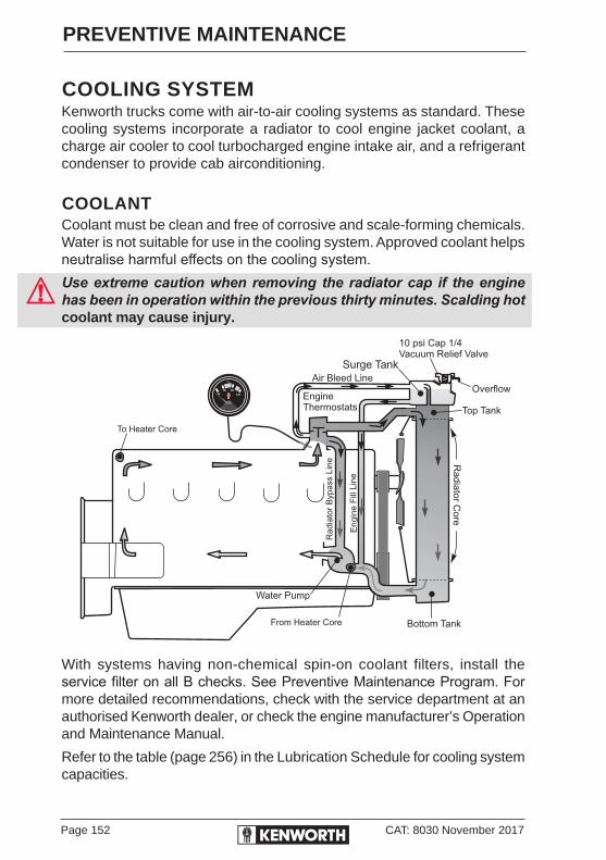
Page 152 CAT: 8030 November 2017
PREVENTIVE MAINTENANCE
COOLING SYSTEMKenworth trucks come with air-to-air cooling systems as standard. These cooling systems incorporate a radiator to cool engine jacket coolant, a charge air cooler to cool turbocharged engine intake air, and a refrigerant condenser to provide cab airconditioning.
COOLANTCoolant must be clean and free of corrosive and scale-forming chemicals. Water is not suitable for use in the cooling system. Approved coolant helps neutralise harmful effects on the cooling system.Use extreme caution when removing the radiator cap if the engine has been in operation within the previous thirty minutes. Scalding hot coolant may cause injury.
With systems having non-chemical spin-on coolant filters, install the service filter on all B checks. See Preventive Maintenance Program. For more detailed recommendations, check with the service department at an authorised Kenworth dealer, or check the engine manufacturer’s Operation and Maintenance Manual.
Refer to the table (page 256) in the Lubrication Schedule for cooling system capacities.
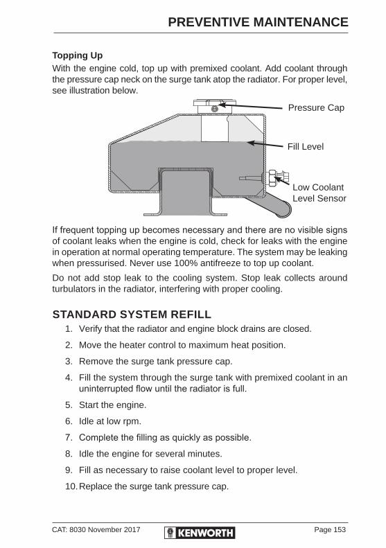
CAT: 8030 November 2017 Page 153
PREVENTIVE MAINTENANCE
Topping UpWith the engine cold, top up with premixed coolant. Add coolant through the pressure cap neck on the surge tank atop the radiator. For proper level, see illustration below.
If frequent topping up becomes necessary and there are no visible signs of coolant leaks when the engine is cold, check for leaks with the engine in operation at normal operating temperature. The system may be leaking when pressurised. Never use 100% antifreeze to top up coolant.
Do not add stop leak to the cooling system. Stop leak collects around turbulators in the radiator, interfering with proper cooling.
STANDARD SYSTEM REFILL1. Verify that the radiator and engine block drains are closed.
2. Move the heater control to maximum heat position.
3. Remove the surge tank pressure cap.
4. Fill the system through the surge tank with premixed coolant in an uninterrupted flow until the radiator is full.
5. Start the engine.
6. Idle at low rpm.
7. Complete the filling as quickly as possible.
8. Idle the engine for several minutes.
9. Fill as necessary to raise coolant level to proper level.
10. Replace the surge tank pressure cap.
Pressure Cap
Fill Level
Low CoolantLevel Sensor
Page 154 CAT: 8030 November 2017
PREVENTIVE MAINTENANCE
Do not mix coolants of different brands or types. If brand or type of coolant is changed, the cooling system must be drained and flushed prior to refill.Check coolant level after each trip when the engine has cooled. Add coolant as necessary. Time must pass for all the trapped air to be purged from the system.
Kenworth Radiators with De-Aeration System - When installing Kenworth radiators that have a built-in surge tank, the engine fill-line or anti-cavitation line and air bleed line (see illustration on page 152) MUST be connected to the engine, and connected correctly. If these lines ARE NOT connected, it will be impossible to fill the cooling system with coolant and engine failure is inevitable.
The air bleed line (No. 6 Aeroquip Hose) connects into the engine side of the engine thermostat. This line allows air to bleed from the running engine when the engine thermostat is closed. It also allows air to bleed from the engine when filling the cooling system.The anti-cavitation line (1” heater hose) connects into the suction side of the coolant pump. This line supplies non-agitated coolant to the pump, to prevent cavitation. Both the anti-cavitation line and the air bleed line should take a continuous downward route from the radiator to their engine inlets. It also allows the cooling system to be filled with coolant.NOTES:
Cooling system capacities are provided as a guide only. Actual coolant fill will vary with equipment, i.e. heat exchanger, sleeper heater etc.Maintain proper coolant concentration levels. Do not permit excessive concentration.
Antifreeze solutions containing antileak additives will quickly restrict a coolant filter and render it ineffective.Do not add rust inhibitors, radiator sealants or water pump lubricants containing soluble oil to the coolant. The additives can deactivate the anticorrosion chemicals.
For more information on maintenance of the cooling system refer to Cooling System - Section 12 CAT: 8080 in your Electronic Customised Maintenance Manual. Fill quantities are on pages 256.

CAT: 8030 November 2017 Page 155
PREVENTIVE MAINTENANCE
BRAKE SYSTEMTo operate your vehicle safely, you need some understanding of its brake systems. Brake adjustment and brake balance must be set carefully to allow equal stopping forces at all wheels. Tyres are also a very important part of the whole system. How fast you can stop depends on how much friction there is between the road and your tyres.
The following areas are interrelated and must conform to original specifications:
• Tyre size.
• Cam radius.
• Slack adjusters.
• Drum radius.
• Brake linings.
• Brake chambers.Once a brake system is set to specifications, changing any of its components may cause system degradation. All parts have to work together to perform as they should. Because your brake system is air-operated, see Air Supply System on page on 161 for more information on checking your brakes. Any replacement components in the brake system should be the same or better than the original components. Any changes from the original specifications can affect the performance of the entire system.Do not work on the brake system without the parking brake set and wheels chocked securely. If the vehicle is not secured to prevent uncontrolled vehicle movement, it could roll and cause serious personal injury or damage to the vehicle.
• Use wood blocks (100 mm X 100 mm or larger) against the front and rear surfaces of the tyres. Be sure the vehicle cannot move.

Page 156 CAT: 8030 November 2017
PREVENTIVE MAINTENANCE
LubricationCam-actuated brake components such as anchor pins and brake camshafts are subjected to high temperatures. They must be lubricated with non-melting, water resistant brake grease meeting R-S Specification 0-616 (NLGI-Grade 2).
• Lubricate according to Recommended Maintenance Schedules, pages 239-264.
Do not apply too much lubricant to brake components - lubricate sparingly. Excessive amounts of lubricant could contaminate brake linings, which could reduce brake effectiveness and cause an accident.
Brake and Slack Adjuster LubricationAccording to the interval, pressure lubricate the slack adjuster and brake camshaft (bracket/tube). Two grease fittings are provided for both the slack adjuster and camshaft (bracket/tube).
• Use standard chassis lubricant which meets No. 1 grade high temperature, waterproof specifications.
• Do not use moly-sulphide loaded grease or oil as it may shorten the service life of the slack adjuster.
• Do not use pressure-release grease fittings when lubricating the slack adjuster.
Checks and AdjustmentsBrakes should be checked regularly.
Always adjust the brakes when they are cool.
• Park the vehicle on a level surface and block the wheels before attempting any brake checks or adjustments.
BRAKE LININGS• Brake linings should be inspected by a qualified mechanic at an
authorised service centre for wear. See Maintenance Schedule, pages 239-264. In severe service applications, inspect the linings more frequently.

CAT: 8030 November 2017 Page 157
PREVENTIVE MAINTENANCE
AUTOMATIC SLACK ADJUSTERSDuring preventive maintenance on an in-service brake, check both the free stroke as described below and the adjusted chamber stroke as described on page 158.
FREE STROKE MEASUREMENTYour Kenworth may be equipped with automatic brake (slack) adjusters. Periodically, brake adjustment should be checked using the following procedure:
1. Check brakes when the temperature of the brake linings is cool and the system air pressure is at 827 kPa (120 psi) maximum.
2. Release the parking brakes to allow the slack adjusters to retract.
3. Measure the retracted pushrod length from the face of the brake chamber to the centre of the pushrod pin.
4. Have another person apply and hold the brakes one full application, measure the same distance.
5. The difference is the pushrod travel distance (applied stroke).Verify the result is within the correct range (see Table on page 158 - Brake Adjuster Application). Correctly installed and functioning brakes (automatic slack adjusters) will produce the strokes listed for each chamber type. Test the vehicle to ensure that the brake system is working correctly before returning a vehicle into service.
"X" Released Position
"Y" Applied Position
Free Stroke = Y Minus XDrum brake free strokemust be 1/2-5/8 in(12.7-15.9 mm)
"X""Y"
Disengage a pull pawl or remove a conventional pawl

Page 158 CAT: 8030 November 2017
PREVENTIVE MAINTENANCE
ADJUSTED CHAMBER STROKE
Automatic Brake Adjuster ApplicationAir Chamber Type (size) Brake Pushrod Travel (applied
stroke)
20-24 Front 25-44 mm
16 Front 19-34 mm
30 Rear 38-51 mm
If the pushrod travel reaches the above specifications, check the slack adjuster installation. Inspect brake adjuster and anchor bracket for damage. The anchor bracket should be tight.
With the air system at 827 kPa (120 psi), apply the brake.
If adjustment is necessary and the slack adjuster is working, the adjusting hex nut will rotate during the chamber return stroke. Installing a spanner on the hex nut will make this easier to see. On each stroke after the first, the amount of adjustment and chamber travel will be less.
Constant manual adjustment of automatic slack adjusters can shorten the life of your internal clutch. If the installation appears to be free of damage, but the applied stroke range could not be achieved, the slack adjuster must be replaced.
The brake adjuster alone does not ensure proper brake operation. Inspect all brake components. All brake components work together and must be checked periodically to ensure the brake system works properly. See the Electronic Customised Maintenance Manual for more information on brake maintenance.
Mark push rod here to measure stroke
120 psi in air tank. Engine OFF
STROKE
• Spring brakes released• Service brakes - not applied
• Spring brakes released• Service brakes applied
CAT: 8030 November 2017 Page 159
PREVENTIVE MAINTENANCE
ANTI-LOCK BRAKING SYSTEM (ABS)Below are some general notes on your Kenworth anti-lock braking system. For detailed service information see the Kenworth Maintenance Manual. All service work should be performed by a qualified technician at an authorised service centre. The foundation brake system must be in proper working order to ensure the best ABS performance.
Before welding anywhere on the vehicle detach the ABS Electronic Control Unit (ECU) connector and all other electronic control units. Never detach the ECU connector with the ignition turned ON.
ABS FAULT CODESFor fault codes related to the ABS system refer to BW2428 or BW2429 "EC-60-ABS/ATC Controllers" (system specific) under Air System section on your Electronic Customised Maintenance Manual Section 4 - Braking, in the Driver Information Pack.
Check ABS wiring harnesses and piping periodically for chafing or other problems. No regular maintenance is required on the ABS components. During wheel balancing, dyno testing, or any time the ignition is ON with part of the ABS disconnected, a failure code will be recorded. Consult your authorised Kenworth dealer for information on clearing the failure code.
If one wheel on any driven axle continues to slip or spin for approximately 4 seconds, this will cause the ABS controller for that axle to go into the fail-safe mode, and the warning light will give a shutdown signal.
In this case the ABS system can be turned back on, and the warning light extinguished by turning the key switch OFF and ON, after the vehicle has been brought to a full stop. When the key switch is turned back on, the warning light will illuminate and remain on for 3 to 5 seconds. This is a built-in function test of the warning light.
If, due to operating conditions, a brake application causes either wheel on the same axle to begin skidding, wheel speed sensors immediately signal the ABS controller in the modulator assembly. The controller responds instantly by signaling the solenoids in the modulator, which activate the air valves, reducing application pressure as needed to prevent the wheels from locking up. If this over-riding correction is effective, application pressure is allowed to build up to the original input.

Page 160 CAT: 8030 November 2017
PREVENTIVE MAINTENANCE
Any malfunction of the ABS system on one or more axles will cause the system to fail-safe, and the panel-mounted amber warning light will come on, indicating both a malfunction and automatic shut-down of the system. If the air system is intact (indicated by the pressure gauges), the service brakes will continue to function normally, but without benefit of the ABS feature.Do not attempt to recycle the ABS system by turning the keyswitch OFF and ON until the vehicle has been brought to a full stop and the parking brakes set. Failure to do so could adversely affect steering and braking control, and may result in loss of vehicle control and an accident.
Do not operate the vehicle in the event of a malfunction in any air circuit. Such a malfunction may prevent the brake system from operating properly and could result in an accident. The vehicle should not be operated until the system is repaired and both braking circuits, including all pneumatic and mechanical components, are working properly.

CAT: 8030 November 2017 Page 161
PREVENTIVE MAINTENANCE
AIR SUPPLY SYSTEMPrior to the removal of any air system component, always block and hold the vehicle by a secure means other than the vehicle’s own brakes. Depleting air system pressure may cause a vehicle to roll unexpectedly resulting in an accident and/or injury. Keep hands away from chamber push rods and slack adjusters; they may apply as system pressure drops.
• Never connect or disconnect a hose or line containing air pressure. It may whip as air escapes. Never remove a component or pipe plug unless you are certain all system pressure has been depleted.
• Never exceed recommended air pressure and always wear safety glasses when working with air pressure. Never look into air jets or direct them at anyone.
• Never attempt to disassemble a component until you have read and understood recommended procedures. Some components contain powerful springs and injury or death can result if they are not properly disassembled. Use only proper tools and observe all precautions pertaining to the use of those tools.
• Do not release the parking brake or attempt to move the vehicle until air pressure in both circuits is at least 690 kPa, the level required for normal brake operation.
• Do not use the trailer hand brake control to hold vehicle while parked. This control utilises air pressure for brake application. Because acceptable air leakage levels cause all truck air systems to gradually lose pressure, vehicle rollaway could occur, resulting in an accident and/or injuries.
• Always apply the tractor and trailer parking brakes when the vehicle is unattended.
Contamination of the air supply system is the major cause of problems in air-operated components such as brake valves and suspension height control valves. To keep contaminants to the lowest possible level, follow these maintenance procedures.
Page 162 CAT: 8030 November 2017
PREVENTIVE MAINTENANCE
AIR SYSTEM FUNCTION TESTScheduled maintenance should be performed on the Kenworth air system, as outlined in the Kenworth Maintenance Manual Section 5 CAT: 8047. In addition, perform an Air System Function Test at least every 3 months or if there is any indication of a potential problem.
AIR TANKSTo eject moisture from the air system tanks, pull the line that is connected to the moisture ejection valve. Continue pulling until the air comes out free of water.
WATER EJECTION VALVES
DailyThe supply and service air tanks must be drained on a daily basis. Operate air devices daily to circulate lubricants within the unit.
PeriodicallyClean filter screens ahead of the valves by removing the screens and soaking them in solvent. Blow them dry with pressurised air before reinstalling them.
If the supply and service tanks are not drained at the recommended frequency, water could enter the air lines and valves. This could cause corrosion or blockage, which could compromise the brake system safety and potentially cause an accident.
Do not use penetrating oil, brake fluid, or wax-based oils in the air system. These fluids may cause severe damage to air system components.
• Maintain the air compressor to prevent excessive oil by-pass. See the Kenworth Maintenance Manual for maintenance details.
• Replace worn seals in valves and air motors as they are needed. Your Kenworth dealer carries rebuild kits for most units.
CAT: 8030 November 2017 Page 163
PREVENTIVE MAINTENANCE
AIR COMPRESSOR
OPERATIONAll compressors, regardless of make or model, run continuously while the engine is running. System pressure is controlled by the governor which (acting in conjunction with the unloading mechanism in the compressor cylinder block) starts and stops compression of air by loading or unloading the compressor when pressure in the system reaches a minimum of 690 kPa or a maximum of 827 kPa (100-120 psi).
Preventive MaintenanceThe following service checks are provided for your information only and should be performed by a certified mechanic. Contact your authorised Kenworth dealer or consult the Kenworth Maintenance Manual and the engine manufacturer’s Maintenance Manual for further information on servicing air compressors. After completing any repairs to the air system, always test for air leaks, and check the brakes for safe operation before putting the vehicle into active service.
• Inspect compressor air filter element, if so equipped, and replace element if clogged. Check compressor mounting and drive for alignment. Adjust if necessary.
• Remove compressor discharge valve cap nuts and check for presence of excessive carbon. If excessive carbon is found, clean or replace the compressor cylinder head. Also, check compressor discharge line for carbon, and clean or replace the discharge line if necessary.
• Disassemble the compressor and thoroughly clean and inspect all parts. Repair or replace all worn or damaged parts, or replace compressor with a factory exchange unit.
Page 164 CAT: 8030 November 2017
PREVENTIVE MAINTENANCE
AIR GAUGES AND AIR LEAKSYour Kenworth comes with two separate air pressure gauges for two separate systems, Primary and Secondary. The Primary gauge indicates pressure in the rear braking system, the Secondary gauge indicates pressure in the front braking system. Each gauge indicates the amount of air pressure in kilopascals (kPa).
Do not operate the vehicle if a leak in the air system is detected. Conduct the following procedure and contact an authorised Kenworth dealer (or any other properly equipped service centre) if a leak is detected. Failure to check the brakes or follow these procedures could cause a system failure, increasing the risk of an accident.If the light and alarm do not turn off at start-up, do not try to drive the vehicle until the problem is found and fixed. If the pressure in either or both systems is too low for normal brake operation, (i.e. the pointer of one gauge falls below 414 kPa (60 psi)), a warning light on the gauge will glow and the audible alarm will sound.
Follow the procedure below to check the compressed air system for leaks, periodically or after maintenance or replacement of air system components:
1. Build up air pressure in the system to the governor cut out point or until 827 kPa (120 psi) is reached.
2. Stop the engine and release the service brakes.
3. Without applying the brake pedal, observe the rate of air pressure drop. This rate should not exceed 14 kPa (2 psi) per minute.
4. Start the engine and build up the air pressure again.
5. Stop the engine, and apply the brakes fully. Apply the brake pedal and hold it down for five minutes. The pressure drop should not exceed 21 kPa (3 psi) per minute.
6. If you detect excessive leakage (air pressure loss greater than 21 kPa (3 psi) after five minutes of brake application), a leakage test should be made at the air line connections and at all air brake control units. These tests should determine where air is escaping.

CAT: 8030 November 2017 Page 165
PREVENTIVE MAINTENANCE
TURBOCHARGERWhen servicing the air intake and exhaust systems on a turbocharged engine, check the following items:
Lubricating System: Check oil lines, housing and connections. Look for leaks, damage or deterioration. Leaks could mean you have damaged oil lines or oil seals.
Manifold: With the engine operating, check for leaking manifold or flange gaskets.
High Frequency Vibration: Vibration may indicate turbo rotor imbalance. Have your authorised Kenworth dealer investigate this immediately. Delay could lead to severe and expensive damage to your vehicle.
Do not operate engine with turbocharger intake piping disconnected. A suction is created when the engine is running. This suction could draw your hand or anything else near it into the impeller fan. You could be seriously injured.
Always keep the intake piping connected when running the engine.

Page 166 CAT: 8030 November 2017
PREVENTIVE MAINTENANCE
TYRES
TYRE INFLATION AND LOADINGRegular and frequent inspection, and proper care will give you the assurance of safe, reliable tyre operation.
Most tyre wear problems are caused by under inflation as the result of slow leaks. Low pressure is the tyres worst enemy; it allows tyres to flex badly and this causes high temperatures to build up. Heat causes early tyre damage such as flex breaks, radial cracks and ply separation. Furthermore, low tyre pressures can affect control of your vehicle, particularly at the front wheels.
TYRE INSPECTION AND REPLACEMENTVisually inspect your tyres frequently for any abnormal conditions such as scrapes, bulges and uneven wear. This must be done immediately after known or suspected contact with an object on the road, pothole, road irregularity or after severe braking. Refer these conditions to an authorised tyre service centre for repair or replacement. Never drive on a tyre if such conditions appear.
If the tyre looks underinflated, stand off to the side and check for damage to the wheel assembly. This can be done by visually comparing the wheel in question to other wheels on the vehicle. For dual wheel assemblies, check between the wheels for damage. If any damage is found, or you suspect damage, do not attempt further repair. Call for expert tyre service.
Do not operate vehicle with underinflated tyres. The extra heat caused by underinflation can cause sudden tyre failure such as a blow out. Low pressure may affect control at the front wheels, which could result in an accident and serious injury. Keep your tyres inflated to the tyre manufacturer’s recommended air pressure.
Tyre thumping during the walk around inspection will tell if a tyre is deflated. The correct way to check tyre pressure is with an accurate gauge. This should be done regularly; at least once a week if operating on a heavy schedule.

CAT: 8030 November 2017 Page 167
PREVENTIVE MAINTENANCE
TYRE INFLATIONMost tyre wear problems are caused by underinflation. So you will want to check tyre pressure regularly. Give the tyres a visual test every day and check inflation with a gauge every week. When checking tyre pressure, inspect each tyre for damage to sidewalls, cuts, cracks, uneven wear, rocks between dual wheels (tyres) etc. If a tyre appears underinflated, check for damage to the wheel assembly. Do not forget to check between dual wheels. If you find wheel damage, have an expert tyre service repair it.Pressure should be checked when the tyres are cool. Warm or hot tyres cause pressure buildup and will give you an inaccurate reading. Never deflate a warm tyre to the specified pressure. Underinflated tyres will adversely affect the operation of the vehicle and tyres:
• Making steering difficult.
• Causing extra strain on the tyre sidewalls.
• Reducing the tread life of tyres due to the high temperatures generated from excess flexing of the tyre.
Recommended maximum vehicle operating speed, 100 km/h.
Recommended Laden Tyre Pressures
Application Rim Size Tyre Size Cold Inflation Pressure
Steer TyresExcept
All Sizes385/65R22.5
827 kPa (120 PSI)620 kPa (90 PSI)
Drive Tyres All Sizes 689 kPa (100 PSI)
Trailer Tyres All Sizes 689 kPa (100 PSI)
For full tyre pressure specifications laden and unladen, refer to the tyre manufacturer for details.
Inflate tyres to the manufacturer’s cold-air pressure specification moulded into the tyre sidewall. Do not exceed these specifications.
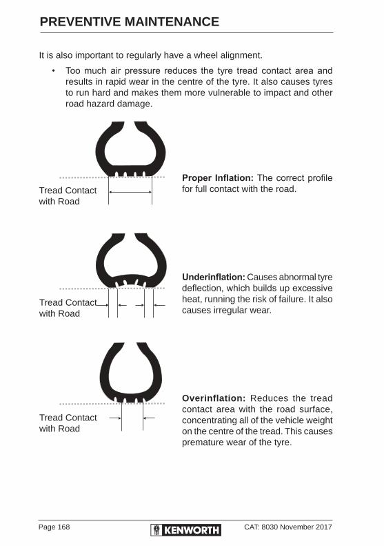
Page 168 CAT: 8030 November 2017
PREVENTIVE MAINTENANCE
It is also important to regularly have a wheel alignment.
• Too much air pressure reduces the tyre tread contact area and results in rapid wear in the centre of the tyre. It also causes tyres to run hard and makes them more vulnerable to impact and other road hazard damage.
Proper Inflation: The correct profile for full contact with the road.
Underinflation: Causes abnormal tyre deflection, which builds up excessive heat, running the risk of failure. It also causes irregular wear.
Overinflation: Reduces the tread contact area with the road surface, concentrating all of the vehicle weight on the centre of the tread. This causes premature wear of the tyre.
Tread Contactwith Road
Tread Contactwith Road
Tread Contactwith Road
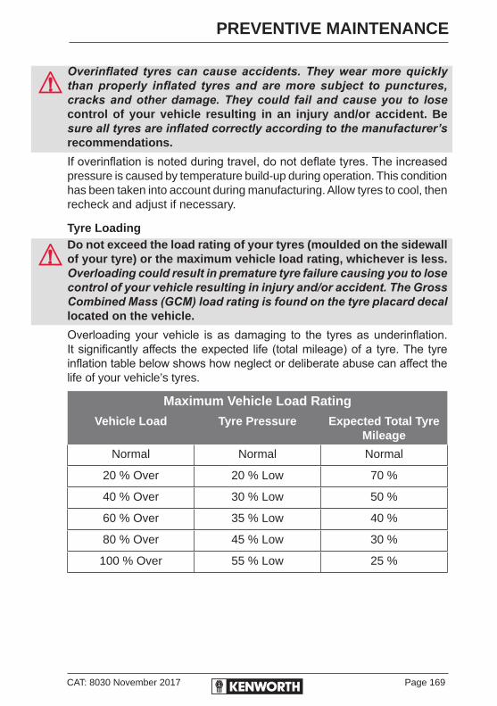
CAT: 8030 November 2017 Page 169
PREVENTIVE MAINTENANCE
Overinflated tyres can cause accidents. They wear more quickly than properly inflated tyres and are more subject to punctures, cracks and other damage. They could fail and cause you to lose control of your vehicle resulting in an injury and/or accident. Be sure all tyres are inflated correctly according to the manufacturer’s recommendations.
If overinflation is noted during travel, do not deflate tyres. The increased pressure is caused by temperature build-up during operation. This condition has been taken into account during manufacturing. Allow tyres to cool, then recheck and adjust if necessary.
Tyre LoadingDo not exceed the load rating of your tyres (moulded on the sidewall of your tyre) or the maximum vehicle load rating, whichever is less. Overloading could result in premature tyre failure causing you to lose control of your vehicle resulting in injury and/or accident. The Gross Combined Mass (GCM) load rating is found on the tyre placard decal located on the vehicle.
Overloading your vehicle is as damaging to the tyres as underinflation. It significantly affects the expected life (total mileage) of a tyre. The tyre inflation table below shows how neglect or deliberate abuse can affect the life of your vehicle’s tyres.
Maximum Vehicle Load Rating
Vehicle Load Tyre Pressure Expected Total Tyre Mileage
Normal Normal Normal
20 % Over 20 % Low 70 %
40 % Over 30 % Low 50 %
60 % Over 35 % Low 40 %
80 % Over 45 % Low 30 %
100 % Over 55 % Low 25 %
Page 170 CAT: 8030 November 2017
PREVENTIVE MAINTENANCE
REPLACING TYRESFront tyres should be replaced before less than 3 mm of tread remains. This does not include tie-bars or tread wear indicators. Replacement tyre and rim sizes must conform with those listed on the “Tyre Decal”, which is located in the cab (see pages 223-224) on all trucks manufactured up to December 31st 2004.
For vehicles built after January 1st 2005, cold inflation tyre pressure limit is marked on individual tyres. Recommended laden tyre pressures are listed on page 167.
Check tread depth in any major tread groove at three locations around the tyre, spaced 120° apart.
Tyres on drive axles or trailer must be replaced when less than 1.5 mm of tread depth remains in any major groove, as checked at 120° locations around tyre.
Regrooved tyres, or tyres with reinforcement repairs, should never be used on steering axles.
MATCHING TYRESIn addition to having tyres balanced, and having their radial and lateral run-out checked, we recommend that you have an authorised Kenworth dealer match your tyres, particularly on the rear axles. Mismatched tyres can cause interaxle conflict and unusually high axle lubricant temperatures. Matched tyres will help lengthen driveline service life and mileage.

CAT: 8030 November 2017 Page 171
PREVENTIVE MAINTENANCE
WHEEL NUT TORQUEAt the first scheduled lube interval, have all wheel nuts torqued to their specified value. Thereafter, wheel nuts MUST be checked at least once a week. Contact the service department at any authorised Kenworth dealership for information on torque values applicable to the wheels installed on your truck or see the table below.
The tightening sequence applies to all wheels except Gunite rims. Wheel nuts must be tightened in three stages, in the sequence shown below, for the particular wheel type, using a suitable calibrated torque wrench, making sure not to rotate captive washers.
Tightening sequence must be strictly adhered to or misalignment may occur. Never tighten nut fully while others are loose.
WHEEL MOUNTING AND FASTENING
6-Spoke Hub-Piloted
SIX SPOKE WHEEL NUT TORQUE
Stud Threads N.M. Ft. Lb
Lightly Lubricated 305–332 225–245
STEEL/ALUMINIUM DISC WHEEL NUT TORQUE
Stud Threads N.M. Ft. Lb
Lightly Lubricated 610-678 450-500

Page 172 CAT: 8030 November 2017
PREVENTIVE MAINTENANCE
VEHICLE JACKINGOrdinary pedestal jacks are designed ONLY to LIFT a vehicle. Once lifted, the vehicle should be supported by other appropriate means, such as stands. NEVER get under, or work under, a vehicle supported ONLY by a jack. Only work under a vehicle supported by stands and with wheels chocked.
20 TONNE HYDRAULIC BOTTLE JACKComplies with AS/ANZ 2693:2007
Minimum height "lowered" 278 mmMaximum height "raised" 458 mmYour 20 tonne hydraulic jack is supplied with an ISO 15 grade Hydraulic Oil. ALLLube Diesel Engine Oil may also be used in your hydraulic jack.
Use only oils that meet the manufacture’s recommended specifications. Never mix different types or different specification oils
ANY JACK SHOULD BE USED ON LEVEL FIRM GROUND WHEREVER POSSIBLE.
NO PERSON SHOULD PLACE ANY PORTION OF THEIR BODY UNDER A VEHICLE THAT IS SUPPORTED BY A JACK; USE VEHICLE SUPPORT STANDS.
WHEELS NOT BEING JACKED SHOULD BE “CHOCKED”. NO PERSON SHOULD REMAIN IN A VEHICLE THAT IS BEING JACKED.
INCORRECT USE MAY RESULT IN POSSIBLE LOSS OF LOAD, DAMAGE AND PERSONAL INJURY.
When the jack leaves the factory the oil chamber contains the correct amount of oil. Before using for the first time, stand jack on base on a level surface, remove the oil reservoir plug and check the oil level. The oil level should be within 3 mm of the bottom of the filler hole when the ram is completely lowered.
Sometimes during shipment, or when changing the oil, air may get trapped in the hydraulic system causing poor performance. To purge any air from the system place the jack in an upright position, open the oil reservoir plug, place a cloth over the filler hole and pump the handle 7 to 10 times in quick succession. This will purge any air from the system.

CAT: 8030 November 2017 Page 173
PREVENTIVE MAINTENANCE
JACK OPERATING INSTRUCTIONSBefore use: Visually inspect the jack for any abnormal conditions and refer to the preceding WARNINGS, SAFE USAGE STATEMENTS and NOTES below.
There may be circumstances where dirt or residue on the ball seat may cause the jack to lower quickly and the jack handle to fly up in force. This may result in damage to the jack handle or personal injury. Where ever possible the jack should be positioned to ensure that the jack handle does not come into contact with any part of the vehicle whilst it is being used. Check that there is a sufficient gap between the jack handle at its highest point and the vehicle before pumping the handle up and down to raise the load.
FOR SAFE USE, IT IS RECOMMENDED THAT:1. Ensure the vehicle’s parking brakes are applied.
2. Chock all road wheels that are to remain on the ground.
3. Remove the key from the ignition, or turn OFF the electrical master switch.
4. No person should remain in a vehicle that is to be jacked.
5. Position the jack beneath the axle to be lifted. A 20-tonne jack will be required when changing a road wheel. Do not use road springs as a jacking point. Position the jack under the axle of, and as close as practicable to, the wheel to be changed.
6. The jack must be seated on a level, flat hard surface, such as concrete, bitumen or compacted road metal.
7. NEVER use a jack as a sole means of support. Position suitable stands or supports under chassis frame.
8. Vehicles either jacked up or hanging up on chain hoists should be blocked with axle stands or substantial timber blocking.
Ordinary pedestal jacks are designed ONLY to LIFT a vehicle. Once lifted, the vehicle should be supported by other appropriate means, such as stands. NEVER get under, or work under, a vehicle supported ONLY by a jack. Only work under a vehicle supported by stands and with wheels chocked.
TO RAISE THE LOAD1. With the jack in the lowered position, turn the release valve with
the end of the jack handle in a clockwise direction until it is firmly closed.
Page 174 CAT: 8030 November 2017
PREVENTIVE MAINTENANCE
2. To maximise the lifting height, unscrew the extension screw/head cap to the required height.
3. Insert the handle into the handle sleeve. Check that the handle or any part of your hand or arm does not come into contact with the vehicle when the handle is at its highest point. If it does, change the position of the jack under the load or lifting point. Raise the ram by operating the handle up and down until contact is made with the lifting point.
4. Position the head cap centrally under the load or lifting point and ensure the load is applied through the centre of the head cap.
Off-centre loads and loads lifted while jack is not sitting level may result in damage and/or injury.
5. Pump the handle up and down to raise the load to the required height.
6. Place support stands in the correct position under the load.
7. Slowly turn the release valve counter clockwise, just sufficiently to allow a gradual decent of the load onto the support stands.
TO LOWER THE LOAD1. Close the release valve. Operate the jack to raise the ram to the
correct position under the vehicle. Raise the load until the support stands are free. Remove the stands clear of the load.
2. Slowly turn the release valve counter clockwise using the end of the handle just sufficiently to allow a gradual descent of the load. If the ram is still partially raised after the load has fully descended, slowly open the release valve one full turn and push the ram down to its lowest position.
GENERAL CARE OF YOUR JACK1. To add oil with the ram fully lowered, set the jack in an upright
position. Wipe away any oil or foreign matter from around the oil reservoir plug then remove it. The oil level should be 3mm below the filler hole.
2. When jack is not in use, the ram, handle sleeve and extension screw should be in the fully lowered position. This will protect precision machined surfaces from corrosion.
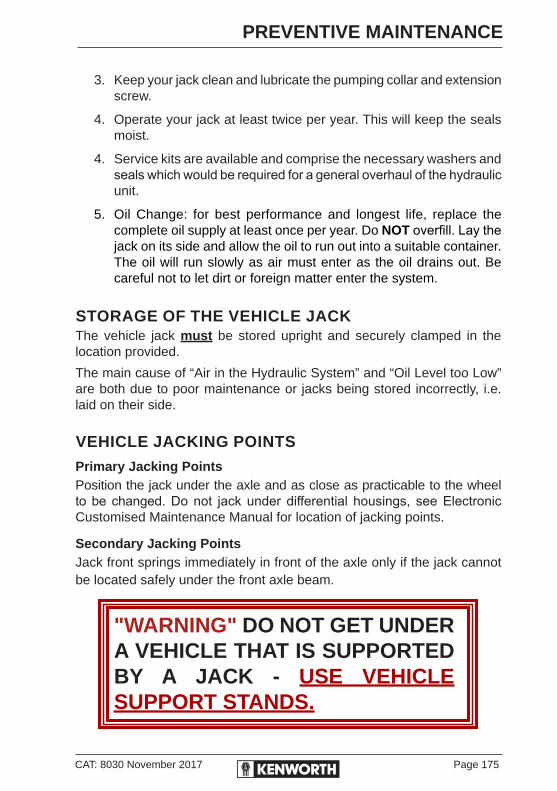
CAT: 8030 November 2017 Page 175
PREVENTIVE MAINTENANCE
3. Keep your jack clean and lubricate the pumping collar and extension screw.
4. Operate your jack at least twice per year. This will keep the seals moist.
4. Service kits are available and comprise the necessary washers and seals which would be required for a general overhaul of the hydraulic unit.
5. Oil Change: for best performance and longest life, replace the complete oil supply at least once per year. Do NOT overfill. Lay the jack on its side and allow the oil to run out into a suitable container. The oil will run slowly as air must enter as the oil drains out. Be careful not to let dirt or foreign matter enter the system.
STORAGE OF THE VEHICLE JACKThe vehicle jack must be stored upright and securely clamped in the location provided.
The main cause of “Air in the Hydraulic System” and “Oil Level too Low” are both due to poor maintenance or jacks being stored incorrectly, i.e. laid on their side.
VEHICLE JACKING POINTS
Primary Jacking PointsPosition the jack under the axle and as close as practicable to the wheel to be changed. Do not jack under differential housings, see Electronic Customised Maintenance Manual for location of jacking points.
Secondary Jacking PointsJack front springs immediately in front of the axle only if the jack cannot be located safely under the front axle beam.
"WARNING" DO NOT GET UNDER A VEHICLE THAT IS SUPPORTED BY A JACK - USE VEHICLE SUPPORT STANDS.

Page 176 CAT: 8030 November 2017
PREVENTIVE MAINTENANCE
BATTERIESBattery Care
Regular attention to the charging system will help prolong the service life of batteries. Common causes for battery failure are:
Isolation SwitchEssential for vehicles carrying dangerous loads i.e. petroleum products, gases, acids, explosives etc. The switch is designed to shut off all battery power, this will disable the Remote Keyless Entry and radio pre-sets in order to maintain total emergency electrical isolation.
Field Isolated AlternatorA field isolated alternator is fitted to the vehicle when battery isolation switch is installed. A field isolated alternator must be used when replacing alternator in service.
BatteriesIf a hydrometer check indicates that a battery is less than 80% charged, the battery should be recharged to full capacity (See table on page 180 Hydrometer Readings).
OverchargeImproper voltage regulator setting results in overheating, warped plates and “boiling off” of electrolyte.
UnderchargeVoltage regulator faulty or improperly set, drive belt slipping, long periods of standing idle or short-distance driving results in battery plates becoming “sulphated” with a hard coating.
VibrationLoose battery hold-downs can result in battery plate failure.
Dirty or Loose ConnectionsThese can stop the flow of electrical power to and from the battery.
Short CircuitsThese will discharge the battery through electrical “leaks”.
SLOW CHARGING: If the battery(s) has lost its charge gradually over a long period of time, recharge at 6 to 8 amps for about 8 to 10 hours.
CAT: 8030 November 2017 Page 177
PREVENTIVE MAINTENANCE
FAST CHARGING: If the battery(s) has lost its charge rapidly, from cranking an engine that failed to start, recharge at 30 to 40 amps for 1 to 2 hours.
A rapid charge rate generates an explosive mixture of hydrogen and oxygen gases. A spark or flame near a battery on charge could cause the battery to explode with considerable force. When fast charging, remove caps so that pressure does not build up.
HeatHeat from other adjacent components can cause overheating of batteries, resulting in warped plates and “boiling off” of electrolyte. Check that any necessary heat shields are in place and that adjacent components are not overheating.
BATTERY CHARGINGExcept for using small trickle charges (slow battery charge, as explained on page 179) to maintain battery condition, you should have your vehicle’s batteries charged by a qualified service facility.Batteries can injure you severely. They contain acid, produce poisonous and explosive gases, and supply levels of electric current high enough to cause burns. A spark or flame near a battery on charge may cause it to explode with great force.
To help reduce the risk of personal injuries, follow these guidelines carefully when recharging a battery:
• Before attempting any service in the electrical installation, disconnect the battery negative cable.
• Allow no sparks or open flame anywhere near the charging area.
• Charge a battery only in a well-ventilated area, such as outdoors or in a fully open garage which contains no pilot lights or other flames. Gases generated during the charging process must be allowed to escape.
• Maintain the full level of electrolyte in the batteries. This reduces the volume of gas in the cells. The electrolyte level should always be between 10 and 15 mm above plates. Fill with distilled water only. After distilled water has been added, wait at least 30 minutes to measure solution density (specific gravity). The specific gravity should be between 1.258 and 1.265 or the electrolyte level within “MIN” and “MAX” marks.

Page 178 CAT: 8030 November 2017
PREVENTIVE MAINTENANCE
• When fast charging, remove the battery caps so pressure does not accumulate.
• Always make sure the battery charger is OFF before connecting or disconnecting the cable clamps.
• To avoid short circuits and damage to yourself or the vehicle, never place metal tools or jumper cables on the battery or nearby. Metal that accidentally comes in contact with the positive battery terminal or any other metal on the vehicle (that is in contact with the positive terminal) could cause a short circuit or an explosion.
Charging Reminders1. Use protective eyewear.
2. Keep all batteries away from children.
3. Never reverse battery poles.
4. Never attempt to place the vehicle in motion, or run the engine with batteries disconnected.
5. Keep the battery clean and dry.
6. Look for any signs of damage.
Never use a metal funnel to add distilled water. It could come in contact with a terminal, creating a short circuit, and resulting in severe personal injury or damage to your vehicle.
Always shield your eyes and avoid leaning over the battery whenever possible. Electrolyte in batteries could splash up into your eyes causing severe burns and/or serious personal injury.
• Battery terminals should not be coated with improper grease. Use petroleum jelly or commercially available, non-corrosive, non-conductive terminal coatings.
• Battery acid that may spill during charging should be washed off with a solution of warm water and baking soda to neutralise the acid. If you accidentally get acid in your eyes or on your skin, immediately rinse with cold water for several minutes and call a doctor.
• Do not charge a frozen battery; allow it to thaw out first. Always allow the battery to thaw gradually. Do not apply direct heat. Gas trapped in the ice may cause an explosion.
CAT: 8030 November 2017 Page 179
PREVENTIVE MAINTENANCE
• Never use a fast charger as a booster to start the engine. This can seriously damage sensitive electronic components such as engine management systems, radio, etc., as well as the battery charger. Fast charging a battery is dangerous and should only be attempted by a competent mechanic with the proper equipment.
Slow Battery ChargingIf a battery has lost charge gradually over a long period of time, recharge at 6 to 8 amps for about 8 to 10 hours.
• Follow the instructions that come with your battery charger.
• It is not necessary to remove the battery from the compartment.Charger cables must be connected positive to positive (+ to +) and negative to negative (- to -). If connected improperly, batteries could explode causing serious personal injury.
1. Always make sure the battery charger is OFF before connecting or disconnecting the cable clamps. To reduce the danger of explosions and resulting personal injury, do not connect or disconnect charger cables while the charger is operating.
2. Make sure the electrolyte level in each cell is between the “MIN” and “MAX” marks. If the fluid level is below the mark, correct the condition.
3. Disconnect the battery cables.
4. Connect charger cables.
5. Start charging the battery at a rate not over 6 amperes. Normally, a battery should be charged at no more than 10 percent of its rated capacity.
6. After charging is complete, switch off charger and disconnect charger cables from the batteries.
Batteries should be charged at least once a month to ensure longer battery life.
A rapid charge rate generates an explosive mixture of hydrogen and oxygen gases. A spark or flame near a battery on charge could cause the battery to explode with considerable force. When fast-charging, remove caps so that pressure does not build up.
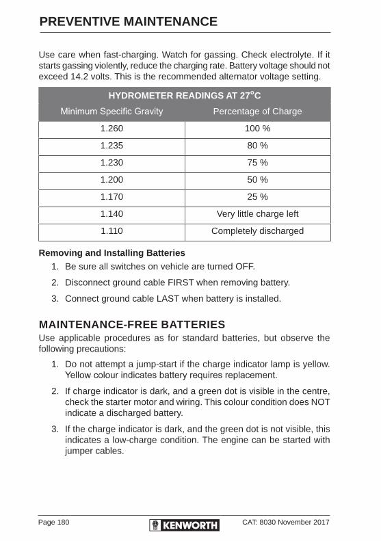
Page 180 CAT: 8030 November 2017
PREVENTIVE MAINTENANCE
Use care when fast-charging. Watch for gassing. Check electrolyte. If it starts gassing violently, reduce the charging rate. Battery voltage should not exceed 14.2 volts. This is the recommended alternator voltage setting.
HYDROMETER READINGS AT 27°C
Minimum Specific Gravity Percentage of Charge
1.260 100 %
1.235 80 %
1.230 75 %
1.200 50 %
1.170 25 %
1.140 Very little charge left
1.110 Completely discharged
Removing and Installing Batteries1. Be sure all switches on vehicle are turned OFF.
2. Disconnect ground cable FIRST when removing battery.
3. Connect ground cable LAST when battery is installed.
MAINTENANCE-FREE BATTERIESUse applicable procedures as for standard batteries, but observe the following precautions:
1. Do not attempt a jump-start if the charge indicator lamp is yellow. Yellow colour indicates battery requires replacement.
2. If charge indicator is dark, and a green dot is visible in the centre, check the starter motor and wiring. This colour condition does NOT indicate a discharged battery.
3. If the charge indicator is dark, and the green dot is not visible, this indicates a low-charge condition. The engine can be started with jumper cables.
CAT: 8030 November 2017 Page 181
PREVENTIVE MAINTENANCE
ELECTRICAL SYSTEMS - 12 AND 24 VOLT A vehicle with a 12V system/24V starting circuit should be jump-started ONLY with a vehicle having the SAME kind of system and ground.
Jump-starting a vehicle with a 12-24V circuit requires two pairs of jumper cables.
Observe all applicable precautions set out above, and connect the jumper cables as follows:
1. Use one pair of cables to connect the vehicle-load (“A”) battery on the “Booster” vehicle to the vehicle-load battery on the inoperative vehicle.
2. Use the other pair of cables to connect the cranking (“B”) battery on the “Booster” vehicle to the cranking battery on the inoperative vehicle. Observe polarity when connecting cables.
JUMP-STARTING WITH BOOSTER BATTERY
THIS IS NOT RECOMMENDED UNLESS IN AN EMERGENCYProper jump-starting of a vehicle requires certain precautions and procedures. The information below is offered to help prevent possible personal injury or damage to the electrical system.
Any procedures other than those described could cause:
• Personal injury from electrolyte spurting out of battery vent.• Personal injury or property damage due to battery explosion.• Damage to the charging system of either vehicle.
Before Connecting Jumper Cables1. Be sure BATTERIES in both vehicles have SAME GROUND.
2. Set BRAKES on both vehicles. Put TRANSMISSIONS in NEUTRAL.
3. Turn ALL SWITCHES OFF in both vehicles, then start engine in the “Booster” vehicle.
Do not attempt to jump-start with vehicles touching. Use cables heavy enough to transmit the power.
When connecting jumper cables, take care to prevent the clamps on one cable from touching the clamps on the other cable. Do not lean over batteries when making connections.

Page 182 CAT: 8030 November 2017
PREVENTIVE MAINTENANCE
Connect Jumper Cables as follows:Standard Batteries — Negative Ground
1. Clamp end of one cable to POSITIVE post on “Booster” battery, then clamp other end of same cable to POSITIVE post on “Dead” battery.
2. Clamp end of other cable to NEGATIVE post on “Booster” battery, then clamp the other end of this cable to the vehicle with the “Dead” battery, at least 30 cm from the battery to make a good ground connection. Do not connect to the grounded post of the “Dead” battery.
Disconnecting Jumper CablesAs soon as jump-starting is accomplished, disconnect the jumper cables:
1. Unclamp the ground cable(s) from the vehicle that was inoperative, then remove the cable(s) from the “Booster” battery.
2. Unclamp the other cable(s) from the vehicle that was inoperative, then remove the cable(s) from the “Booster” battery.
CAT: 8030 November 2017 Page 183
PREVENTIVE MAINTENANCE
WELDING PRECAUTIONS
FOR VEHICLES WITH ELECTRONIC INSTRUMENTATIONTo prevent damage to gauges, interface modules and other electronic and electrical equipment, disconnect the battery cables before electric arc welding on a vehicle. If arc welding of any frame-mounted components is required, ensure the welding ground lead is connected directly to the component, preferably directly adjacent to the weld groove. Bearings and other parts will be damaged if electric current must pass through them when completing the circuit.
Welding to frame rail will void frame rail warranty.
FOR VEHICLES WITH ELECTRONIC ENGINESObserve these recommended procedures to protect electronic systems during welding operations.
If ABS system is installed, disconnect ECU. Servicing Systems and Units refer to Electronic Customised Maintenance Manual, Section 4 - Braking, BW2428 or BW2429.
1. With the engine turned OFF, disconnect all electronic connections to the vehicle batteries.
2. Remove battery power cable and insulate it from the vehicle.
3. Disconnect all Electronic Control Module (ECM) connectors (on electronic engines).
4. Do not use the ECM or engine ground stud for the ground of the welding probe.
5. Ensure the ground connection for the welder is as close to the weld point as possible. This ensures maximum weld current and minimum damage to electrical components on the vehicle.
Page 184 CAT: 8030 November 2017
PREVENTIVE MAINTENANCE
CHASSIS AND CAB – FINISH, APPEARANCE AND CLEANING
CHASSIS AND CAB
THE ENAMEL ON THIS VEHICLE IS NOT YET HARDENED. DO NOT STEAM CLEAN, WAX, POLISH, OR RUB THE FINISH UNTIL A MINIMUM 45 DAYS AFTER DELIVERY. CLEAN WITH COLD WATER AND SPONGE ONLY.
High pressure washers and steam cleaners can dislodge seals and enter electrical circuits causing serious damage to the vehicle's systems.
Painted SurfacesPPG recommend the following precautions in the first thirty (30) days:
• Do not use silicone containing waxes or polishes.
• Apply decals/stickers to fully cured finishes only.
• Do not use a high pressure lance any closer than 450mm or 18 inches from the paint surface.
• Do not use a commercial car wash. Stiff brushes or coarse sponges could mar the finish and damage the surface. Wash the vehicle by hand with cool water and a very mild car wash solution. Be sure to use a soft cloth or soft sponge.
• Wash the vehicle in the shade - never in the sun.
• Do not “dry wipe” the vehicle - always use clean fresh water. Dry wiping could scratch the finish.
• Extreme heat and cold should be avoided. Keep the vehicle parked in the shade wherever possible.
• Try to avoid gravel roads. Stone chipping the finish is easily done in the first thirty (30) days.
• Do not park under trees, which drop sap, or near factories with heavy smoke fallout. Sap and industrial fallout can mark or spot a freshly painted surface.
CAT: 8030 November 2017 Page 185
PREVENTIVE MAINTENANCE
• Trees are also likely to attract birds. Bird droppings have a high acid content and will damage a freshly painted surface. Droppings should be washed off as soon as possible.
• Try to avoid spilling petrol, oil, anti-freeze, transmission fluid, brake fluid and windshield solvent on the new finish. If this happens wash it off immediately.
• If the vehicle is to be stored, avoid using non-breathing covers on finishes under 30 days old.
Wash frequently to remove grime and caustic deposits which could stain the finish. Use cool or lukewarm water. A mild soap may be used. Avoid washing in bright sunlight. Road tar can be removed with a special commercial tar remover or mineral spirits. Waxing offers added protection against staining and oxidation. Wait approximately 90 days after date of manufacture before waxing to give the finish a chance to cure. Do not wax in hot sun. If a buffing machine is used, take care not to friction-burn the paint.
Aluminium and Chrome SurfacesAluminium wheels and bumpers can be cleaned with warm water. Tar remover will take off heavy deposits of road grime. For added appearance, wipe aluminium surfaces dry after washing to prevent spotting. Under corrosive conditions such as driving on salted roads, clean aluminium pans with steam or high-pressure water from a hose. A mild soap solution will help. Rinse thoroughly.
Chrome surfaces are best cleaned with fresh water. Wipe dry to preserve lustre. Light rust can be successfully removed with any commercial chrome cleaner. After cleaning, wax flat surfaces and apply a thin coat of rust preventive lubricant around bolts or other fasteners.
InteriorVinyl upholstery and lining should be wiped clean with any good grade commercial vinyl upholstery cleaner. DO NOT use chemicals such as acetone or lacquer thinner. Fabric upholstery can be cleaned with upholstery shampoo specially formulated for this purpose. Follow instructions on the container.
Cleaning of Cabin TrimAside from its classic aesthetic appearance, one of the features of the vinyl trim used inside all Kenworth cabs is the material’s ease of maintenance. The vinyl offers exceptional service life if given proper care.

Page 186 CAT: 8030 November 2017
PREVENTIVE MAINTENANCE
For the material to be maintained properly, it is important that you are aware of the correct methods for cleaning the trim so as to avoid any accidental damage which may occur if the wrong cleaning products are used.
The procedures used for cleaning depend on the nature of the spill or stain. Below are some common stains which are likely to be encountered in a truck environment.
Everyday SpillageIn general, most common stains can easily be cleaned using a mixture of mild soap and warm water. Wash the area to be cleaned with a soft cloth or sponge, rinse thoroughly and dry. If stubborn dirt remains in the grain of the vinyl, use a soft brush to scrub the area.
InkWork quickly! Permanent solvent-based markers and ball point pen ink will affect the pigments and for the most part are difficult to remove from any vinyl if allowed to dry. A solution of water and methylated spirits should be applied with a soft cloth as soon as possible to remove the stain.
PaintCautious use of turpentine will remove fresh paint. Immediately rinse with a soap and water solution.
Oil & GreasePetroleum based products will stain all vinyls if allowed to stand too long. Clean as soon as possible using a soft cloth and eucalyptus oil to wipe clean. Rinse with a soap and water mixture.
BloodRub out any spots with a clean cloth soaked in cool water. If stubborn spots remain, use household ammonia and rinse repeatedly with a clean wet cloth. Do not use hot water or soap as this will set the stain.
Use of harsh solvents, cleaners containing abrasives, steel wool and industrial strength cleaners are not recommended on vinyl materials. Use of these products will adversely affect the material finish.Only use small quantities of mild solvent-based cleaners such as turpentine when they are required. After use of any solvent-based cleaner or other cleaning product, it is important to immediately wash the vinyl surface with a mild soap and water solution. Continual use of solvent-based cleaners will shorten the life of the vinyl material.

CAT: 8030 November 2017 Page 187
PREVENTIVE MAINTENANCE
Weather-strippingOccasionally spray weather-stripping on doors and windows with silicone compound to help preserve resiliency. This is especially useful in freezing weather to keep doors and windows from sticking shut with ice.
It is good practice to hose dirt and grime from the whole chassis. If an oil leak develops, it will be more easily detected.
ENGINEDo not spray high-pressure water onto the engine’s electronic control module or wiring harnesses. Moisture can enter the harness connectors resulting in poor electrical contact and subsequent electronic failures.
STEERING WHEEL
CARE/MAINTENANCESpecial care and attention must be taken to prolong the life of your steering wheel.
Do not use the steering wheel as a means of support for entering the cab, do not wear oily/greasy gloves whilst driving and be aware of the destructive nature of hand jewellery, i.e. rings, chains and wristwatches.
CLEANINGClean only with a warm soapy cloth (do not use solvent based or wax based cleaning products).
For further washing information refer to your Electronic Customised Maintenance Manual, Section 11, CAT: 8051.
Page 188 CAT: 8030 November 2017
PREVENTIVE MAINTENANCE
CAB HEATER/AIRCONDITIONINGThe combination heater/airconditioner provides comfort for those in the cab through accurate control of the cab environment in all weather conditions. Regular attention to the items below will help you keep the heater/airconditioner performance at an optimal level.
Keep the vehicle’s ventilation system, engine exhaust system and cab/sleeper joints properly maintained. It is recommended the vehicle’s exhaust system and cab/sleeper be serviced as follows:
• Inspected by a competent technician every 10,000 kilometres.
• Whenever a change is noticed in the sound of the exhaust system.
• Whenever the exhaust system, underbody cab or sleeper is damaged.
To allow for proper operation of the vehicle ventilation system:
• Keep the inlet grille clear of leaves and other debris at all times.
• Inspect and clean fresh air inlet filter to HVAC unit at 10,000 kilometre intervals.
• Keep the exhaust pipe area clear to help reduce the buildup of exhaust gas under the vehicle.
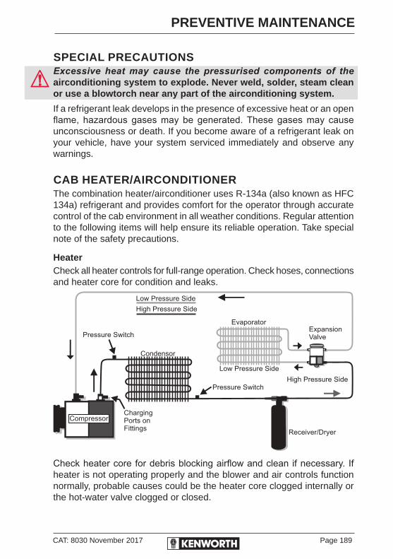
CAT: 8030 November 2017 Page 189
PREVENTIVE MAINTENANCE
SPECIAL PRECAUTIONSExcessive heat may cause the pressurised components of the airconditioning system to explode. Never weld, solder, steam clean or use a blowtorch near any part of the airconditioning system.
If a refrigerant leak develops in the presence of excessive heat or an open flame, hazardous gases may be generated. These gases may cause unconsciousness or death. If you become aware of a refrigerant leak on your vehicle, have your system serviced immediately and observe any warnings.
CAB HEATER/AIRCONDITIONERThe combination heater/airconditioner uses R-134a (also known as HFC 134a) refrigerant and provides comfort for the operator through accurate control of the cab environment in all weather conditions. Regular attention to the following items will help ensure its reliable operation. Take special note of the safety precautions.
HeaterCheck all heater controls for full-range operation. Check hoses, connections and heater core for condition and leaks.
Check heater core for debris blocking airflow and clean if necessary. If heater is not operating properly and the blower and air controls function normally, probable causes could be the heater core clogged internally or the hot-water valve clogged or closed.

Page 190 CAT: 8030 November 2017
PREVENTIVE MAINTENANCE
AIRCONDITIONERAny servicing that requires depressurising and recharging the airconditioning system should be conducted by a qualified licensed technician with proper facilities.
Check compressor belt for condition and proper tension (see pages 150-151 for applicable data).
Check compressor and drive clutch for noise and vibration. If problems exist, have the system checked thoroughly. A bad clutch usually indicates troubles elsewhere in the system.
Check the condenser core for debris restricting air flow and clean if necessary. Small particles can be removed with compressed air blown through the core in reverse of normal air flow.Check recirc inlet for blockage. K200: Inlet vent on HVAC behind cover panel at passenger's foot well could be blocked. Conventional: Inlet vent on inside of firewall could be blocked.Use eye protection when blowing air through the core.
Check all hoses for kinks, deterioration, chafing and leaks. Kinked hoses must be replaced with new hoses and the cause of kinking eliminated. On tilt-cab installation, be sure that hoses are routed around the pivot point in such a way that lifting the cab does not strain them.
Check all components and connections for refrigerant leaks. Do not attempt to tighten a connection if a leak exists. This usually indicates other problems, and tightening a fitting could cause a worse leak. Have the problem corrected by a qualified technician.Have the airconditioning system fully serviced annually by your authorised Kenworth dealer, as it requires evacuating and recharging the system, using specialised equipment.
Keep any open flame away from the area. Even a match or cigarette lighter can generate a hazardous quantity of phosgene gas.Do not smoke in the area. People have become violently ill just from inhaling gaseous refrigerant through a lighted cigarette.
CAT: 8030 November 2017 Page 191
PREVENTIVE MAINTENANCE
SAFETY RESTRAINT SYSTEMThe seatbelt system, including webbing, buckles, latches and mounting hardware, endures heavy use in heavy-duty vehicles - much more than seatbelt systems in passenger cars. All users should be aware of the factors contributing to this heavy use and reduced belt life.
Failure to properly inspect and maintain restraint systems can lead to serious injury or loss of life. Without periodic inspection and maintenance to detect unsafe conditions, seat restraint components can wear out or not protect you in an accident.
Factors contributing to reduced seat belt life:• High mileage - Heavy trucks often accumulate mileage in excess
of 1,000,000 kilometres during the vehicle lifetime. This is much greater than a typical passenger car, which frequently will not exceed 200,000 kilometres.
• Seat and cab movement - In trucks, there is almost constant movement of the belt due to ride characteristics and seat design. The constant movement of the belt inside the restraint hardware and the potential for the belt to come in contact with the cab and other vehicle parts contribute to the wear of the entire system.
• Environmental conditions, such as dirt and ultraviolet rays from the sun, will reduce the life of the seat belt system.
Due to these factors, the three-point safety belt system installed in your vehicle requires thorough inspection every 30,000 km. If the vehicle is exposed to severe environmental or working conditions, more frequent inspections may be necessary.
Any seatbelt system that shows cuts, fraying, extreme or unusual wear, significant discolouration due to UV (ultraviolet) exposure, abrasion to the seatbelt webbing, or damage to the buckle, latch plate, retractor hardware or any other obvious problem should be replaced immediately, regardless of mileage.

Page 192 CAT: 8030 November 2017
PREVENTIVE MAINTENANCE
INSPECTION GUIDELINESFollow the guidelines below when inspecting for cuts, fraying, extreme or unusual wear of the webbing, and damage to the buckle, retractor, hardware, or for other factors. Damage to these areas indicates that belt system replacement is necessary.
It is important to remember that any time a vehicle is involved in an accident, the entire seatbelt system must be replaced. Unexposed damage caused by the stress of an accident could prevent the system from functioning properly the next time it is needed, which could result in severe injury or even death. Replace the entire belt system (retractor and buckle side) if replacement of any one part is necessary.
Unexposed damage to one or more components could prevent the system from functioning properly the next time it is needed, which could result in severe injury or even death. The following points refer to the illustration on page 193.
1. Check the web wear in the system. The webbing must be closely examined to determine if it is coming into contact with any sharp or rough surfaces on the seat or other parts of the cab interior. These areas are typical places where the web will experience cutting or abrasion. Cuts, fraying, or excessive wear would indicate the need for replacement of the seat belt system.
2. The shoulder web guide is the area where almost constant movement of the seat belt webbing occurs because of relative movement.
3. Inspect the seatbelt reel/retractor, which is mounted on the side or rear of the seat, for damage. The retractor is the heart of the occupant restraint system and can often be damaged if abused, even unintentionally. Check operation to ensure that it is not locked up and that it spools out and retracts webbing properly.
The KAB554B retractor is designed to automatically lock when the cab is not level. The truck should be on level ground and the angle of the belt relative to the seat needs to be correct to ensure that automatic lock does not engage.

CAT: 8030 November 2017 Page 193
PREVENTIVE MAINTENANCE
4. Check buckle and latch for proper operation and to determine if latch plate is worn, deformed or damaged.
5. Mounting hardware should be evaluated for corrosion, and for tightness of bolts and nuts.
6. Check web in areas exposed to ultraviolet rays from the sun. If the colour of the web in these areas is grey to light brown, the physical strength of the web may have deteriorated due to exposure to the sun’s ultraviolet rays. If signs of deterioration are detected, replace the system.
1
2
5
6
4
Web cut/frayed at web guide
Web cut/frayed or extremely worn at latch area
Buckle casting broken
Seatbelt reel / retractor
3
Page 194 CAT: 8030 November 2017
PREVENTIVE MAINTENANCE
Once the need for replacement of the seatbelt has been determined, ensure it is only replaced with an authorised PACCAR Parts replacement seatbelt. If the inspection indicates that any part of the seatbelt system requires replacement, the entire system must be replaced.An installation guide is attached to every replacement belt. Utilise the proper guide for your type of seat, and follow the instructions very closely. It is vitally important that all components be reinstalled in the same position as the original components that were removed and that the fasteners be torqued to specification. This will maintain the design integrity of the mounting points for the seat belt assembly.
Contact your authorised Kenworth dealer if you have any questions concerning seat belt replacement.

CAT: 8030 November 2017 Page 195
PREVENTIVE MAINTENANCE
TRANSMISSION AND CLUTCHFollow the procedures below to ensure parts are properly lubricated:
• Maintain oil level, check it regularly.
• Change oil regularly.
• Use the correct grade and type of oil.
• Buy oil from a reputable dealer.
ALL TRANSMISSIONSInitial Change: drain and replace according to Recommended Service Maintenance Schedules on (pages 239-264). For some transmissions this may not be required.
Oil ChangeChange fluid according to change procedures specified in the Transmission Service Manual. Use the recommended types of oil as specified in the Operation and Service Manual (included in your Electronic Customised Maintenance Manual). Select from the appropriate lubricant for varying ambient (outside air) temperatures.
When adding oil, types and brands of oil should not be intermixed because of possible incompatibility, which could decrease the effectiveness of the lubrication or cause component failure.
Manual and Automatic Transmission Oil LevelThe vehicle must be parked on level ground. See the Transmission Operator’s Manual for information on checking the transmission oil level.
Manual TransmissionsBefore checking level, engine must be idling in neutral for at least 2 minutes and lubricant temperature must be between 15.5° and 48.8° C.
Check lubricant level using the fill hole or sightglass (if fitted) usually located on the right side of the transmission. Inspect oil filter for leaks, rust or damage. Replace as necessary.
Check fluid levels and inspect for leaks at regular service intervals, which should not to exceed 20,000 km between intervals.
1. Turn engine off.
2. Remove fill hole plug.
3. Lubricant must be level with the bottom of the inspection hole.

Page 196 CAT: 8030 November 2017
PREVENTIVE MAINTENANCE
Automatic Transmissions
Automatic transmissions are designed so that the internal parts operate in a bath of oil circulated by the motion of gears and shafts. Current Allison 3000 Series Transmissions have a built-in oil level sensor.
Check the oil level, using the diagnostic display on the shift selector as per the Allison Handbook SA3360OEN supplied in the Allison pack, included in the Driver Information Pack, supplied at handover of the truck. This handbook is also in Section 6 on the Electronic Customised Maintenance Manual found in the Driver Information Pack.
Always check the transmission fluid level a minimum of two times. Consistency is important in maintaining accuracy. If inconsistent readings persist, check the transmission breather and the vent hole in the dipstick fill tube to ensure they are clean and free of debris.Take the following precautions so that unexpected, possible sudden vehicle movement is avoided. Whenever it becomes necessary to leave the vehicle, even momentarily, while the engine is running, place the transmission shift selector in N (neutral), set the parking brake and/or emergency brakes and chock the wheels.
Cold CheckThe only purpose of the Cold Check is to determine if the transmission has enough fluid to be safely operated until a Hot Check can be made.
• Park the vehicle on a level surface, set the parking brake and/or emergency brakes, and chock the vehicle wheels.
• Run the engine at 1000-1500 rpm for 1 minute to purge air from the system. Return engine to idle, then shift to D (Drive) and then to R (Reverse) to fill the hydraulic circuits with fluid. Then shift to N (Neutral) and allow the engine to idle (500-800 rpm). A cold check may be made during initial start-up within the first ten minutes of operation when the sump fluid temperature is typically 16-49°C (60-120°F ).
Hot CheckThe fluid level rises as the temperature increases. To ensure an accurate check, operate the transmission until the sump fluid temperature is 71-93°C (160-200°F); converter-out temperature is 82-104°C (180-220°F). If a transmission temperature gauge is not present, check fluid level when the engine water temperature gauge has stabilised and the transmission has been operated under load for at least one hour.

CAT: 8030 November 2017 Page 197
PREVENTIVE MAINTENANCE
• Park the vehicle on a level surface and shift to N (Neutral). Set the parking brake and/or emergency brakes and chock the vehicle wheels. Allow the engine to idle (500-800 rpm).
• Wipe the dipstick clean and check the fluid level. The safe operating range is any level within the HOT RUN band on the dipstick. If the level is not within this band, add or drain fluid as necessary to bring the level to the top of the HOT RUN band.
Approximately one litre of fluid is required to raise the level from the bottom to the top of the band.
TRANSMISSION SERVICE INTERVALSFor recommended types and brands of all lubricants, see the transmission manufacturer’s Service Manual and Recommended Maintenance Schedules and fluid quantities, page 239-264.
MODEL RECOMMENDED LUBRICANT
AMBIENT TEMPERATURE
RANGE - °C
VISCOSITY
(SAE)
Main Transmissions
Eaton Fuller 18*** Series & below
ALLLube Transmission
Mono 50Above 12°C 50
Eaton AutoShift, UltraShift and
20918/22918 Series
Roadranger Lube SAE 50
Castrol Syn 50EAbove 12°C 50
Automatic Transmissions
All Allison Automatic
Transmissions
Castrol TranSynd
Synthetic Oil Above 23°C 30
Transfer Cases
Fabco TC-110, TC0140, TC-800 &
TC-65
ALLLube Transmission Oil
Mono 50Above 12°C 50
Maintain the oil level and check it regularly. Oil should be level with the bottom of the filler plug hole with Manual and AutoShift Transmissions and at the correct level on the dipstick on Allison Automatic Transmissions. Use the diagnostic display on the shift selector (see correct procedure in the Allison Manual in the Driver Information Kit).

Page 198 CAT: 8030 November 2017
PREVENTIVE MAINTENANCE
CLUTCH SYSTEMFree pedal is the distance the clutch pedal moves by applying only slight pressure. During free pedal, the release yoke in the transmission moves until its bearing pads contact the release bearing. This movement of the release yoke is called free travel. Thus, free pedal and free travel are directly related to each other.
As the clutch pedal is depressed further with harder pressure, the release yoke moves the release bearing away from the engine. This causes the clutch plate to release from the driven discs in the clutch. This is called release travel.
And, finally, as the pedal is pushed to the last 12 mm to 25 mm of travel, the release bearing contacts and engages the clutch brake. This is called clutch brake squeeze. When the clutch wears, the release bearing gradually moves toward the engine, decreasing free pedal and free travel.
When all free pedal and free travel are gone, the clutch requires adjustment.
The clutch is adjusted by turning an adjustment ring that is built into the clutch. When the ring is turned, the release bearing moves back toward the transmission restoring free pedal and clutch free travel. Under normal clutch wear, this is the only adjustment needed. Do not attempt to change any other component. See the Kenworth Maintenance Manual for details.
CLUTCH LINKAGEIn addition to the following service recommendations see the Kenworth Maintenance Manual for clutch information. Have your authorised Kenworth service dealer service the clutch according to the clutch manufacturer’s service guidelines.
• All conventional Kenworth are equipped with a rod and lever mechanical clutch linkage. Lubricate each pivot point on the clutch linkage.
External Linkage Adjustment1. Adjust the clutch to the clutch manufacturer’s specification.
2. Verify 6 mm of free travel (distance the release yoke moves before the release yoke bearing pads contact the release bearing).
3. Verify free pedal of 32 mm ± 6 mm.

CAT: 8030 November 2017 Page 199
PREVENTIVE MAINTENANCE
CLUTCH ADJUSTMENT - NORMAL WEARClutch pedal free travel is normally 25 to 38 mm. This should be your guide to determining if clutch adjustment is necessary. On vehicles not equipped with automatic clutch adjustment you should have an authorised Kenworth dealer adjust the clutch before pedal free travel is reduced to the minimum allowable 13 mm.
See the clutch manufacturer’s Service Manual on the Electronic Customised Maintenance Manual for the correct adjustment procedures.
This procedure is all that is required for normal clutch adjustment. Adjustment of any other components is not required.
Clutch brake travel12 - 25 mm (1/2 - 1 in.)
Pedal free travel25 - 38 mm (1 - 11/2 in.)

Page 200 CAT: 8030 November 2017
PREVENTIVE MAINTENANCE
CLUTCH LUBRICATIONTo ensure long life and proper operation of the release mechanism of the clutch it is important to properly lubricate the following areas:
Release BearingThe cast iron bearing housing will be equipped with either a standard grease fitting or a lube tube extension. If a lube tube is not present it is necessary to remove the inspection cover to gain access to the grease fitting. Apply grease until it purges from the rear of the housing. Grease on the transmission input shaft will extend the life of the clutch brake and bronze bushings inside the release sleeve. If your vehicle is equipped with an Eaton Fuller Solo XL (Extended Lube) there will be roller bearings at the end of the clutch release yoke. These bearings are permanently lubed and do not require maintenance.
Release Bearing Wear PadsWhere the release fork contacts the bearing housing there are small hardened steel pads. Apply a small amount of grease to the wear pads where the clutch release fork contacts.
Clutch BrakeThe clutch brake friction material is designed to operate with lubricant. While lubricating the release bearing, grease should purge from the housing and contact the clutch brake. This is beneficial for long clutch brake life. If desired, a small amount of grease could be applied to both sides of the clutch brake.
Cross-Shaft BushingsLubricate both the left and the right cross-shaft bushings as per OEM recommendations.
Clutch Control LinkageLubricate the clutch linkage bell cranks and pivot pins as per OEM recommendations.
Pilot BearingThe pilot bearing inside the flywheel is a sealed for life bearing and requires no lubrications. Use a premium pilot bearing to prevent clutch drag and early bearing failures (C-4 or C-5 Suffix).

CAT: 8030 November 2017 Page 201
PREVENTIVE MAINTENANCE
STEERINGFrequent visual checks of the steering gear and components are vital to driving safety. Check the crosstube for straightness. Check draglink ends, ball joints and steering U-joints for looseness.
Check draglink for evidence of tyre rubbing and draglink clamp for looseness or interference. Check steering wheel free play. It is good practice to make a special check of these components after a hard trip over rough roads.
If the steering feels awkward, check the simplest probable causes first, for example unequal tyre pressures, loose cap nuts, bent crosstube or lack of lubrication. If these checks do not reveal the problem, have the problem diagnosed and corrected by an authorised Kenworth dealer.
While operating the vehicle, the driver should avoid deep ruts or obstructions which cause a binding condition on front wheels. If the front wheels are in a rut or against a curb, the vehicle should be driven out under its own power, rather than lifted out by turning the wheels while the vehicle is stopped.
UNDERSTEER AND OVERSTEERThese are vehicle dynamics terms used to describe the sensitivity of a vehicle to steering. Simply put, oversteer is what occurs when a vehicle turns (steers) by more than (over) the amount commanded by the driver. Conversely, understeer is what occurs when a vehicle steers less than, or ‘under’ the amount commanded by the driver.
Oversteer:
The vehicle turns more sharply than intended and could get into a spin.
Understeer:
The vehicle does not turn enough and leaves the road.
Page 202 CAT: 8030 November 2017
PREVENTIVE MAINTENANCE
AXLE STOPSYour vehicle is equipped with power steering, have an authorised Kenworth dealer make axle stop adjustments. The power steering pressure relief valves must be adjusted in conjunction with the axle stops to prevent damage to the steering gear.
After front axle alignment, it is recommended that axle stops and steering gear poppets are checked for proper relief on turns.
HYDRAULIC POWER STEERING
FILTER SERVICE AND PARTS - RESERVOIR ASSEMBLYThe original filter element should be replaced after a maximum of 50 hours of operation. Thereafter, the element and cover gasket should be replaced after every 40,000 km (1,000 hours of operation), or more often, depending upon operating conditions.
When replacing an element, drain the reservoir and clean the screen at the bottom of the reservoir.

CAT: 8030 November 2017 Page 203
PREVENTIVE MAINTENANCE
STEERING DRIVELINEThe following are common torque specifications for most drivelines:
• Torque on U-joint pinch bolt and nut 7/16", lubricated.
• Torque on Pitman arm clamp bolt and nut 3/4", lubricated.
• For off-highway vehicles, tighten the U-bolts after the first day or two of operation. Then check weekly.
For your particular driveline, see the electronic Customised Kenworth Maintenance Manual.
DRIVESHAFT• Greasable slip joints and universal joints of the drive shaft should
be lubricated periodically.
Use a good quality lithium-soap base or equivalent extreme pressure (E.P.) grease: NLGI Grade 2.
• For towing guidelines and returning a towed vehicle to service see page 134.
U-JOINTS• The slip joints and universal joints of the drive shaft should be
lubricated according to Recommended Maintenance Schedules, pages 239-264.
Use a good quality lithium-soap base or equivalent extreme pressure (E.P.) grease: NLGI Grade 2.
Improper lubrication of U-joints can cause them to fail prematurely. The driveshaft could separate from the vehicle and result in an injury accident and/or vehicle damage. Make sure lubricant is purged at all four ends of each U-joint and loosen caps if necessary. Also, regularly inspect U-joints for excessive wear or movement and repair or replace as necessary.
Page 204 CAT: 8030 November 2017
PREVENTIVE MAINTENANCE
ADJUSTABLE STEERING COLUMNNever adjust your steering column when the vehicle is in motion. Loss of steering may cause an accident.
Column Angle Adjustment• Pull lever on left side of steering column.
• Adjust column angle when holding lever.
• Release lever and check that it is in the fully down position, assuring proper locking.
Height and Tilt Adjustment• Push or pull to adjust height of steering wheel.
• Pull lever up to adjust height, push lever down to adjust tilt.Use of excessive force to lock may create difficulties with further adjustments.

CAT: 8030 November 2017 Page 205
PREVENTIVE MAINTENANCE
FRONT AXLE AND SUSPENSION
AXLE LUBRICATION• Change bearing lubrication when seats are replaced, or brakes are
relined. See Recommended Maintenance Schedules, pages 239-264.
• Thoroughly clean hubs and bearings with solvent and a stiff bristle brush, then dry and inspect components for wear or damage. Re-lubricate with approved axle lubricant.
KINGPIN LUBRICATION• Lubricate with approved lubricant. Lubricate knuckle thrust bearings,
knuckle pins and tie rod ends. See Recommended Maintenance Schedules, page 239-264. Lack of lubrication causes premature wear and hard steering. Lubrication schedule may be shortened if necessary.
The grease fitting for the front drive pins faces inboard to prevent interference with the drag link.
SUSPENSION LUBRICATIONEach standard spring anchor pin has a grease fitting. Pressure lubricate spring pins as specified. See Recommended Maintenance Schedules, page 239-264.
• At regular service intervals, the spring leaves may be lubricated with rust-inhibiting oil applied with a spray gun or brush.
• Depending on your suspension, lubricate all spring pins until grease flows out of both ends of the bushing. Look for signs of rust or water in the flushed grease. If a pin will not accept grease, it should be removed, cleaned and inspected.
Do not spray the suspension with chemical products or mineral oil. It can cause damage to the bushings.

Page 206 CAT: 8030 November 2017
PREVENTIVE MAINTENANCE
VISUAL INSPECTION• For all vehicles mandatory maintenance procedures include re-
tightening all U-bolts and inspecting the suspension for loose fasteners, abnormal wear or damage. However, even with proper maintenance, the service life of leaf springs is affected by many factors, including fatigue, vehicle gross weight, type of load, road conditions and vehicle speed.
• Check for cracks, wear marks, splits or other defects on the surface of the spring. Defective parts must be replaced. Because repaired springs cannot be fully restored to their original service life, replace the complete assembly if cracks or other defects are detected.
• Visually inspect shock absorbers and rubber bushings. See the Electronic Customised Maintenance Manual for further information on servicing the front suspension.
U-BOLT TENSION FOR FRONT AND REAR AXLESIt is important that U-bolts remain tight. Severe use of your vehicle will cause them to loosen faster. All vehicles need to have their U-bolts checked and tightened regularly. Be sure someone with the proper training and the right tools checks and tightens the U-bolts on your Kenworth.
New springs can “settle in” after service relieving the tension on the U-bolts. Loose U-bolts can cause leaf spring breakage, axle misalignment, hard steering and abnormal tyre wear.
Do not operate the vehicle if the U-bolts are not properly tightened. Loose U-bolts will cause the axle to not be properly secured to the suspension, which could cause loss of vehicle control and an accident. Loose U-bolts can also cause uneven tyre wear and poor alignment.
U-bolts are difficult to tighten unless you have the right equipment. If you cannot tighten them correctly yourself, be sure to have them checked and tightened regularly by an authorised Kenworth dealer.
For on-highway vehicles, tighten U-bolts after the first service (10,000 km), and then every 40,000 km thereafter. For off-highway vehicles, tighten U-bolts after the first day or two of operation, then check weekly. Re-torque the front spring pinch bolts and shackle pinch bolts. See the Electronic Customised Maintenance Manual for torque values.
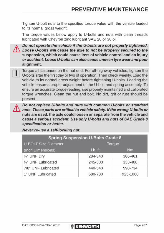
CAT: 8030 November 2017 Page 207
PREVENTIVE MAINTENANCE
Tighten U-bolt nuts to the specified torque value with the vehicle loaded to its normal gross weight.
The torque values below apply to U-bolts and nuts with clean threads lubricated with Chevron zinc lubricant SAE 20 or 30 oil.
Do not operate the vehicle if the U-bolts are not properly tightened. Loose U-bolts will cause the axle to not be properly secured to the suspension, which could cause loss of vehicle control and an injury or accident. Loose U-bolts can also cause uneven tyre wear and poor alignment.
Torque all fasteners on the nut end. For off-highway vehicles, tighten the U-bolts after the first day or two of operation. Then check weekly. Load the vehicle to its normal gross weight before tightening U-bolts. Loading the vehicle ensures proper adjustment of the U-bolt and spring assembly. To ensure an accurate torque reading, use properly maintained and calibrated torque wrenches. Clean the nut and bolt. No dirt, grit or rust should be present.
Do not replace U-bolts and nuts with common U-bolts or standard nuts. These parts are critical to vehicle safety. If the wrong U-bolts or nuts are used, the axle could loosen or separate from the vehicle and cause a serious accident. Use only U-bolts and nuts of SAE Grade 8 specification or better.Never re-use a self-locking nut.
Spring Suspension U-Bolts Grade 8U-BOLT Size Diameter
(Inch Dimensions)
TorqueLb. ft. Nm
¾” UNF Dry 284-340 386-461
¾” UNF Lubricated 245-300 333-408
7/8” UNF Lubricated 440-540 598-734
1” UNF Lubricated 680-780 925-1060

Page 208 CAT: 8030 November 2017
PREVENTIVE MAINTENANCE
WHEEL ALIGNMENT
FRONT WHEEL ALIGNMENTFor driving safety and comfort and to prolong the life of your vehicle, it is important to have wheels correctly aligned. Check tyre wear frequently. Uneven tyre wear is a sign the wheels may be misaligned. If you see uneven wear, take your vehicle to a service centre familiar with aligning wheels on Kenworth vehicles. Consult the table below for alignment specifications for each type of axle.
Camber: Camber figures shown are at unladen chassis weight.
Front Wheel Alignment Kenworth Australia – Specifications
Axle Model Caster (Degrees Positive)
Camber Toe-in
FG 941
FG 943
MFS 73
I-140
E-1322 I
E-1462 I
D2000F
All Models
3.5° ± 1°
All Models
Left -1/4° ± 3/8°
Right +1° ± 3/8°
All Models
0 - +1.5 mm/m
FL 941 3.5° ± 1° +1/4° ± 7/16° 0 - +1.5 mm/m
WHEEL BEARING ADJUSTMENTFor safe, reliable operation and adequate service life, wheel bearings must be checked and properly adjusted. Your authorised Kenworth dealer is best equipped to do this.

CAT: 8030 November 2017 Page 209
PREVENTIVE MAINTENANCE
REAR AXLE AND SUSPENSION
GENERAL MAINTENANCEYour vehicle’s suspension, by design, requires a minimal amount of maintenance. However, suspensions in “over-the-road” operations require periodic inspection to ensure trouble-free performance.
Do not work on the vehicle without the parking brake set and wheels chocked securely, using rubber wheel chocks against the front and rear surfaces of the tyres. Be sure the vehicle cannot move. If the vehicle is not secured to prevent uncontrolled vehicle movement, it could roll and cause serious personal injury or damage to the vehicle.
Failure to maintain the specified torque values or to replace worn parts can cause component system failure, possibly resulting in an accident. Improperly tightened (loose) suspension U-bolts can lead to unsafe vehicle conditions, including hard steering, axle misalignment, spring breakage or abnormal tyre wear. (See the Fastener Torque Tables pages 221-222 for proper torque specifications.)
REAR SUSPENSION FASTENERSTo maintain the performance of the air suspension, check fastener torque values after the first 10,000 km of service and every 40,000 km thereafter.
Torque recommendations apply to fasteners supplied and installed by Kenworth. The values listed in the tables on pages 221-222 are for cadmium-plated or phosphate and oil fasteners only. See the Kenworth Maintenance Manual for complete details on Suspension Maintenance.
U-bolts are difficult to tighten unless you have the right equipment. If you cannot tighten them correctly yourself, be sure to have them checked and tightened regularly by an authorised mechanic.
Page 210 CAT: 8030 November 2017
PREVENTIVE MAINTENANCE
VISUAL INSPECTIONFor all vehicles, mandatory maintenance procedures include re-tightening of U-bolts and complete inspection. However, even with proper maintenance, many factors affect the service life of springs and suspension components, for example fatigue, vehicle gross weight, type of load, road conditions and vehicle speed.
It is important that U-bolts remain tight. Severe use of your vehicle can cause them to loosen faster. All vehicles need to have their U-bolts checked and tightened regularly. Be sure someone with the proper training and the right tools checks and tightens the U-bolts on your Kenworth.
After the first 1,000 km of operation, inspect the suspension periodically, as noted below:
• Visually check for loose or missing fasteners, cracks in hanger or axle connection brackets.
• Check springs are centred in hangers and in good condition.
• Check for cracks, wear marks, splits or other defects on the surface of the spring.
• Replace defective parts. Because repaired springs cannot be fully restored to their original service life, replace the complete assembly if cracks or other defects are detected.
• After replacement of any part or discovery of loose components, check the torque of all fasteners.
• New springs “settle-in” after the vehicle’s initial service, causing the U-bolts to become loose.
Failure to follow these recommendations could void warranty. See the Kenworth Maintenance Manual for further information on servicing the rear suspension.
CAT: 8030 November 2017 Page 211
PREVENTIVE MAINTENANCE
REAR AXLE LUBRICATIONCheck oil level with the vehicle parked on level ground and the fluid warm. The level should be even with the bottom of the filler hole.Do not mix lubricants of different grades, although mixing different brands of the same grade lubricant (meeting MIL-L-2105-C) is acceptable. Lubricants of different grades are not compatible and could damage the axle.In all cases, the lubricant supplier assumes full responsibility for the performance of their product and for product and patent liability.
DANA REAR AXLEPetroleum-based lubricants must be drained within the first 10,000 km if converting to an approved synthetic lubricant.
For recommended types and brands of lubricants, contact your Kenworth dealer or authorised service centre. See the Kenworth Maintenance Manual and the axle manufacturer’s Service Manual for further information on servicing drive axles.
Initial Change: See Recommended Maintenance Schedules (pages 239-264), for standard rear axle service schedules. Change mineral-based lubricant in other Dana axle assemblies (new or rebuilt) within the first 10,000 km.
For petroleum-based axles, use lubricants meeting MIL-L-2105-C/D grade specifications or approved synthetic lubrication. Do not use oil additives.All Vehicles with Dana Axles: See TRSM 0670 service manual on the electronic Customised Maintenance Manual. Contact your Kenworth dealer or authorised service centre for approved synthetic lubricant brands.
MERITOR REAR AXLESee Meritor Lubrication Maintenance Manual (MM1) on the electronic Customised Maintenance Manual.
On-Off Highway: Check every 250 hours of operation.
Change every 2,500 hours of operation thereafter or yearly whichever occurs first.
Page 212 CAT: 8030 November 2017
PREVENTIVE MAINTENANCE
AXLE TECH REAR AXLESee Axle Tech Maintenance Manual AMM5E or AMM9E (axle specific) on the electronic Customised Maintenance Manual.
Off Highway: Check every 250 hours of operation.
Change every 2,500 hours of operation thereafter or yearly whichever occurs first.
SISU REAR AXLESee the maintenance and lubrication schedule located in Section Three of this book or Rear Axle section on the electronic Customised Maintenance Manual. Oil change interval is dependent on duty cycle. Most heavy-duty trucks will require oil change intervals not exceeding 30,000 km. (Refer to Kenworth Trucks approved application details.)
AXLE HOUSING BREATHER VENT (ALL AXLES)• Check and clean the axle housing breather vent at each oil level
check.
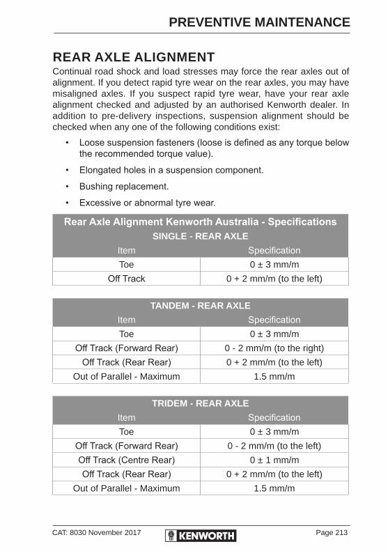
CAT: 8030 November 2017 Page 213
PREVENTIVE MAINTENANCE
REAR AXLE ALIGNMENTContinual road shock and load stresses may force the rear axles out of alignment. If you detect rapid tyre wear on the rear axles, you may have misaligned axles. If you suspect rapid tyre wear, have your rear axle alignment checked and adjusted by an authorised Kenworth dealer. In addition to pre-delivery inspections, suspension alignment should be checked when any one of the following conditions exist:
• Loose suspension fasteners (loose is defined as any torque below the recommended torque value).
• Elongated holes in a suspension component.
• Bushing replacement.
• Excessive or abnormal tyre wear.
Rear Axle Alignment Kenworth Australia - SpecificationsSINGLE - REAR AXLE
Item SpecificationToe 0 ± 3 mm/m
Off Track 0 + 2 mm/m (to the left)
TANDEM - REAR AXLE
Item SpecificationToe 0 ± 3 mm/m
Off Track (Forward Rear) 0 - 2 mm/m (to the right)
Off Track (Rear Rear) 0 + 2 mm/m (to the left)
Out of Parallel - Maximum 1.5 mm/m
TRIDEM - REAR AXLE
Item SpecificationToe 0 ± 3 mm/m
Off Track (Forward Rear) 0 - 2 mm/m (to the left)
Off Track (Centre Rear) 0 ± 1 mm/m
Off Track (Rear Rear) 0 + 2 mm/m (to the left)
Out of Parallel - Maximum 1.5 mm/m

Page 214 CAT: 8030 November 2017
PREVENTIVE MAINTENANCE
REAR SUSPENSION ALIGNMENTCheck and adjust as necessary (refer to Maintenance Manual for your specific suspension).These torque limits are valid ONLY when the U-Bolt and nut threads are clean and have been lubricated with an SAE 20 or SAE 30 oil.
Never re-use a self-locking nut.
TORQUE REQUIREMENTS FRAME FASTENERS
Bolt Size Imperial
Grade 8 Nylon Insert Nuts
Nm ft. lb.
3/8” 41-54 30-40
7/16” 75-88 55-65
½” 109-122 80-90
9/16” 156-190 115-140
5/8” 224-265 165-195
¾” 394-462 290-340
7/8” 517-626 380-460
1” 925-1129 700-830
1-1/8” 1346-1591 990-1170
1-¼” 1822-2217 1380-1630
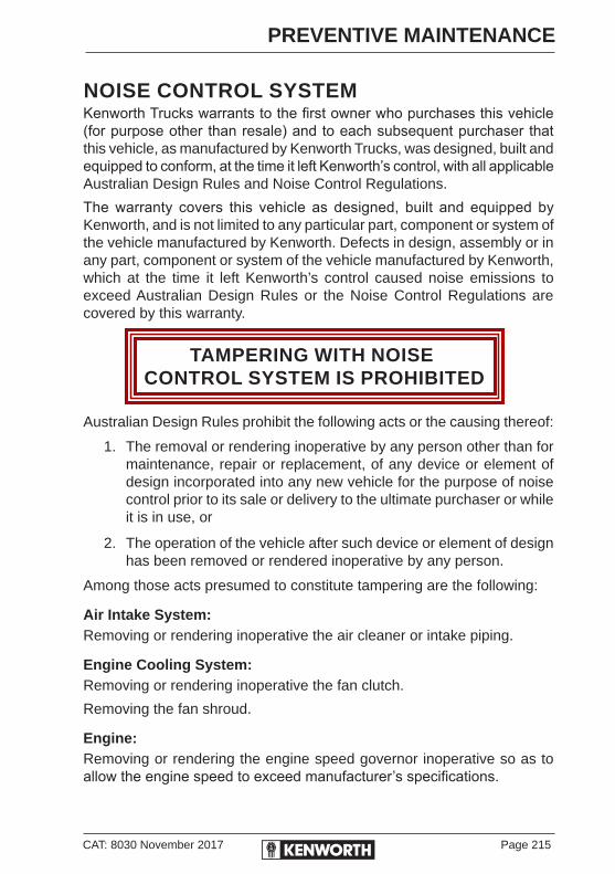
CAT: 8030 November 2017 Page 215
PREVENTIVE MAINTENANCE
NOISE CONTROL SYSTEMKenworth Trucks warrants to the first owner who purchases this vehicle (for purpose other than resale) and to each subsequent purchaser that this vehicle, as manufactured by Kenworth Trucks, was designed, built and equipped to conform, at the time it left Kenworth’s control, with all applicable Australian Design Rules and Noise Control Regulations.
The warranty covers this vehicle as designed, built and equipped by Kenworth, and is not limited to any particular part, component or system of the vehicle manufactured by Kenworth. Defects in design, assembly or in any part, component or system of the vehicle manufactured by Kenworth, which at the time it left Kenworth’s control caused noise emissions to exceed Australian Design Rules or the Noise Control Regulations are covered by this warranty.
TAMPERING WITH NOISE CONTROL SYSTEM IS PROHIBITED
Australian Design Rules prohibit the following acts or the causing thereof:
1. The removal or rendering inoperative by any person other than for maintenance, repair or replacement, of any device or element of design incorporated into any new vehicle for the purpose of noise control prior to its sale or delivery to the ultimate purchaser or while it is in use, or
2. The operation of the vehicle after such device or element of design has been removed or rendered inoperative by any person.
Among those acts presumed to constitute tampering are the following:
Air Intake System:Removing or rendering inoperative the air cleaner or intake piping.
Engine Cooling System:Removing or rendering inoperative the fan clutch.
Removing the fan shroud.
Engine:Removing or rendering the engine speed governor inoperative so as to allow the engine speed to exceed manufacturer’s specifications.

Page 216 CAT: 8030 November 2017
PREVENTIVE MAINTENANCE
Exhaust System:Removing or rendering inoperative the exhaust system components.
The exhaust system is part of the noise control system. Periodically check the exhaust for wear and loose or missing parts.
Inner Fender Shields and Cab Skirts:Removing shields or skirts.
Cutting away parts of shields, skirts or damaged or loose portions of shields or skirts.
Noise-insulation Blankets:Removing noise insulators from engine block or from around the oil pan.
Cutting holes in, or cutting away part of, noise insulators.
Removing hood-mounted noise insulation.
AIR SYSTEM SILENCERSCertain air components in the vehicle's Braking System are fitted with silencers. These silencers need to be inspected on a regular basis, with particular attention being paid to the Air Dryer Purge Tank (if fitted). This can block internally, due to the air supply coming from the engine intake side.
As a routine check it is good practice to apply heavy braking, when stationary, at the start of the day when the truck has warmed up and before entering public roads. This action will ensure higher exhausting pressure.
Road Trains and vehicles driving on unmade roads and dusty conditions, need to check and clean the silencers more frequently.Do not remove these silencers from the system, they can only be removed for cleaning or replacement.
To clean the silencers, use a warm soapy solution, or soak in kerosene or similar product, blowing dry using a low pressure compressed air nozzle. Care must be taken when using compressed air.

CAT: 8030 November 2017 Page 217
PREVENTIVE MAINTENANCE
INSPECTION AND MAINTENANCEUse the following procedures to check the Noise Control System for sources of noise or deterioration that results in noise. Preventive maintenance and repair information is supplied.
Wherever other systems are involved, such as electrical or cooling, reference is made to the applicable sections for more specific information.
Exhaust System:Check for exhaust leaks and condition of gaskets. Replace any blown gaskets.
Check all cap-screws using a torque wrench, including those at the flanges. Refer to the engine manufacturer’s service manual for proper tightening sequence and torque values.
Joints and Clamps:Check for leaks, and tighten as necessary. Check for deterioration or dents in pipes and clamps which could allow exhaust gas to escape.
On tilt-cab installations, check the exhaust ball-joint for condition and proper fit.
Piping:Check exhaust piping for rust, corrosion and damage. Replace deteriorated piping before holes appear. If piping is perforated at any point, temporary patching or lagging is acceptable until permanent repairs can be made.
On turbocharged engines, check joints at flanges and mounting brackets for tightness.
Mufflers:Check muffler clamps and mounting brackets for security. Check internal baffling for security. This can be accomplished by listening for rattling sounds while tapping the muffler with a rubber mallet or by revving the engine up and down through its normal operating range.
Do not replace a damaged muffler with a non-genuine part, as it may affect engine back pressure and/or noise levels, thus exceeding ADR limits.
Exhaust Extension:Check for security of mounting. The opening at the top of the tail pipe must be facing the rear of the vehicle. Do not modify the end of the exhaust extension in any way.

Page 218 CAT: 8030 November 2017
PREVENTIVE MAINTENANCE
Engine-mounted Noise Insulators:Depending on the method of attaching noise insulators on engine and around oil pan (bolts, snap fasteners or straps), check for condition and security. Tighten loose fasteners and repair or replace any worn or damaged fasteners.
Check insulators around fasteners and stress points, particularly where they may be affected by engine vibration. Repair any cracked or damaged mounting points with suitable reinforcing plates to ensure the insulators will remain in position.
Air Intake System:All the maintenance procedures listed under Engine Air Intake System and Air Cleaner in this manual are applicable.
Check the induction tubing, elbow connections, clamps, brackets and fasteners for deterioration, cracks and security. If an air leak exists anywhere between the air cleaner and the engine, it should be repaired immediately. This condition not only causes excessive noise, it can result in serious damage to the engine.
Engine Fan and Shroud:Do not work on the fan with the engine running. The engine fan can engage at any time without warning. Anyone near the fan when it turns ON could be seriously injured. Before turning ON the ignition, be sure that no one is near the fan.
Check all fasteners for tightness. Check for stress cracks in the shroud. Make sure the shroud is adjusted so that it does not touch the blades.
Check the fan assembly mounting bolts for tightness. Inspect the blades for damage. The blade assembly should be replaced if damaged.
Check clutch operation by starting the engine when it is cold, then idling it at about 800 rpm. Check that the fan remains disengaged while the engine is warming up. When the fan clutch does engage, note the reading on the vehicle’s panel-mounted coolant temperature gauge. If the fan clutch engages at low engine temperatures or cycles ON and OFF more frequently than it should (i.e. receives “false signals”), have the problem repaired at an authorised Kenworth dealer.

CAT: 8030 November 2017 Page 219
PREVENTIVE MAINTENANCE
Transmission and Driveline:Substituting different transmission or drive-line components, other than design-specified units, may result in increased vehicle noise emission.
Hood Insulation Blanket:Check all fasteners for condition and security. Repair or replace any broken or defective fasteners.
Check for chafing, tears etc. Patch if necessary. Determine cause of damage. If any component or accessory is causing wear or damage and can’t be relocated, place reinforcing pads on the blanket at the wear spots.
Inner Fender Shields and Cab Skirts:Check all fasteners for security, particularly the self-tapping hex-head screws. Remove and replace any loose rivets.
Check shields and skirts for cracks of mounting stress points. Check fender shields for tyre marks, worn spots or damage from objects thrown from tyre treads. Cracked or damaged fibreglass fender shields can be repaired with fibreglass and resin.If damage is found at a fastening point, additional strength can be gained by using a suitable reinforcing plate - drilled to accept a rivet and laminating it to the shield with fibreglass and resin. Cab skins, sills and brackets should be checked for overall condition, and repaired as necessary. This work can be accomplished at an authorised Kenworth dealership.
Damaged rubber fender shields or cab skirting must be replaced.

Page 220 CAT: 8030 November 2017
PREVENTIVE MAINTENANCE
MAGNETIC DRAIN PLUGSEngines, gear boxes and differentials that have metal on metal contact create friction wear as the metal surfaces wear, giving off a fine greyish metal dust that contaminates the oil. All the contaminants cannot be removed by the oil filter alone, an oil filter is only capable of catching particles over 35 microns as these particles are extremely fineMagnetic drain plugs on engines, gear boxes and differentials perform the vital function of trapping the small metallic particles that circulate in the lubricant.
These abrasive particles can cause rapid wear and premature failure of engine components, gears and bearings.The oil drain plug is a good place to catch these particles and should be cleaned off every time an oil change is performed. The magnets can lose their effectiveness as material collects on the poles and “shorts” the magnetic field. Check the effectivness of your drain plugs, and change plugs before this occurs.
It may be necessary to change plugs one or more times between complete lubrication intervals, particularly during the initial break-in period. We recommend that spare plugs be kept on hand for replacement. Replacement plugs are listed in the Dealer Master Parts Catalogue.
Ready for Removed for
Installation Inspection & cleaning
To facilitate the cleaning of a magnetic drain plug, a piece of key stock, or any other convenient steel slug, may be used to “short” the magnetic field.
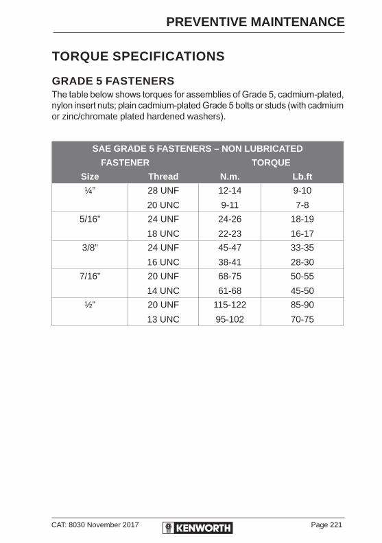
CAT: 8030 November 2017 Page 221
PREVENTIVE MAINTENANCE
TORQUE SPECIFICATIONS
GRADE 5 FASTENERSThe table below shows torques for assemblies of Grade 5, cadmium-plated, nylon insert nuts; plain cadmium-plated Grade 5 bolts or studs (with cadmium or zinc/chromate plated hardened washers).
SAE GRADE 5 FASTENERS – NON LUBRICATED
FASTENER TORQUE
Size Thread N.m. Lb.ft
¼” 28 UNF
20 UNC
12-14
9-11
9-10
7-8
5/16” 24 UNF
18 UNC
24-26
22-23
18-19
16-17
3/8” 24 UNF
16 UNC
45-47
38-41
33-35
28-30
7/16” 20 UNF
14 UNC
68-75
61-68
50-55
45-50
½” 20 UNF
13 UNC
115-122
95-102
85-90
70-75

Page 222 CAT: 8030 November 2017
PREVENTIVE MAINTENANCE
GRADE 8 FASTENERSThe table below shows torques for assemblies of Grade 8, cadmium-plated, nylon insert nuts; plain cadmium-plated Grade 8 bolts or studs (lightly lubricated; with cadmium or zinc/chromate-plated hardened washers).
SAE GRADE 8 FASTENER TORQUE REQUIREMENTS
FASTENER SIZE TORQUE
N.m. Lb.ft
5/16” 22-30 16-22
3/8” 41-54 30-40
7/16” 75-88 55-65
½” 109-122 80-90
9/16” 156-190 115-140
5/8” 224-265 165-195
¾” 394-462 290-340
7/8” 517-626 380-460
1” 952-1129 700-830
1 - 1/8” 1346-1591 990-1170
1 - ¼” 1877-2217 1380-1630
The torque values apply to both UNF and UNC threads of corresponding diameters.
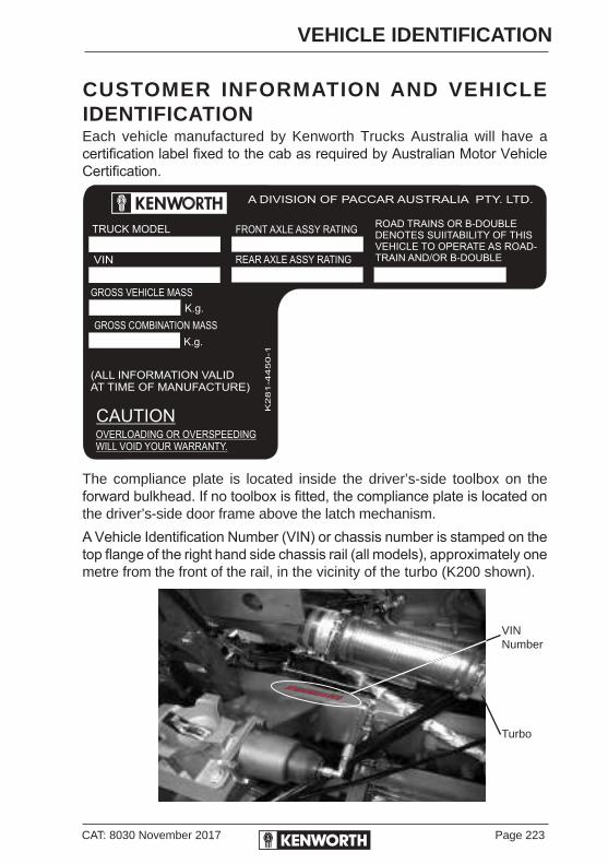
CAT: 8030 November 2017 Page 223
VEHICLE IDENTIFICATION
CUSTOMER INFORMATION AND VEHICLE IDENTIFICATIONEach vehicle manufactured by Kenworth Trucks Australia will have a certification label fixed to the cab as required by Australian Motor Vehicle Certification.
The compliance plate is located inside the driver’s-side toolbox on the forward bulkhead. If no toolbox is fitted, the compliance plate is located on the driver’s-side door frame above the latch mechanism.
A Vehicle Identification Number (VIN) or chassis number is stamped on the top flange of the right hand side chassis rail (all models), approximately one metre from the front of the rail, in the vicinity of the turbo (K200 shown).
6F5000000DA448858
VIN Number
Turbo
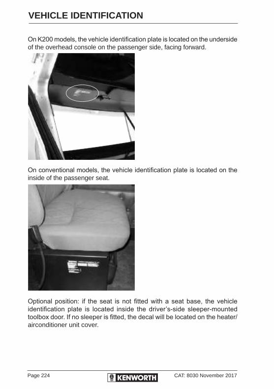
Page 224 CAT: 8030 November 2017
VEHICLE IDENTIFICATION
On K200 models, the vehicle identification plate is located on the underside of the overhead console on the passenger side, facing forward.
On conventional models, the vehicle identification plate is located on the inside of the passenger seat.
Optional position: if the seat is not fitted with a seat base, the vehicle identification plate is located inside the driver’s-side sleeper-mounted toolbox door. If no sleeper is fitted, the decal will be located on the heater/airconditioner unit cover.

CAT: 8030 November 2017 Page 225
VEHICLE IDENTIFICATION
VEHICLE IDENTIFICATION NUMBER (VIN)All trucks are required to have a unique identifying number.ADR43/01, effective 1 January 1989, requires that the format of the VIN comply with ISO standards.
These vary slightly from US SAE standards with regard to year codes.
WMI VDS VIS
A A A + A A A A A A+ A A N N N N N N
A- Alpha character
N N N + N N N N N N + N N N N
N-Numeric character
WMI (World Manufacturer Index)
A A A
A A A
I I I Manufacturer, e.g. Kenworth I I Country, e.g. Australia
I Geographic Region, e.g. Oceania
VDS (Vehicle Descriptor Section)A A A A A A
N N N N N N
Use of VDS is optional, but generally it is used to describe manufacturer specified vehicle attributes.
VIS (Vehicle Indicator Section)A A N N N N N N
N N N N
I I Year of Manufacture/Model Year (I,O,Q,Z not used)I Manufacturer’s Plant
eg 6F5000000FA453770
Kenworth/Australia/Oceania/Nil Data/2015/Bayswater Plant/Unit Number 453770

Page 226 CAT: 8030 November 2017
VEHICLE IDENTIFICATION
SERIAL NUMBERS AND CAPACITIESVIN / Chassis No: ............................................. / .................................
Air comp: Serial No: ...............................................................................
Unit Trans. Model: ..................................................................................
Unit Trans. Serial No: .............................................................................
Aux. Trans. Model: .................................................................................
Aux. Trans. Serial No: ............................................................................
Rear Suspension: ...................................................................................
Rear Axle Model: ...................................... Ratio: ..................................
Fwd. Rear Axle Serial No: ......................................................................
Fwd. Carrier Serial No: ...........................................................................
Centre Rear Axle Serial No: ...................................................................
Centre Carrier Serial No: ........................................................................
Rear Rear Axle Serial No: ......................................................................
Rear Carrier Serial No: ...........................................................................
Rear Axle Capacity: Fwd: ....................... Rear: ..................................
Electrical System 12 Volt, Negative Ground: ..........................................
Total Fuel Capacity: ...................................................................... Litres
Engine Crankcase Capacity: ........................................................ Litres
Radiator Coolant Capacity: ............................................................ Litres
Transmission Capacity: Unit: ........... Litres. .......... Aux: ............. Litres
Rear Axle Capacity: ...............................................................................
Wheel Size: Front: ................................... Rear: ...................................
Fan Belt Part No: ...................................................................................
Alternator Belt Part No: ..........................................................................
Airconditioner Pump Belt Part No: .........................................................
V - I - N CHASSIS
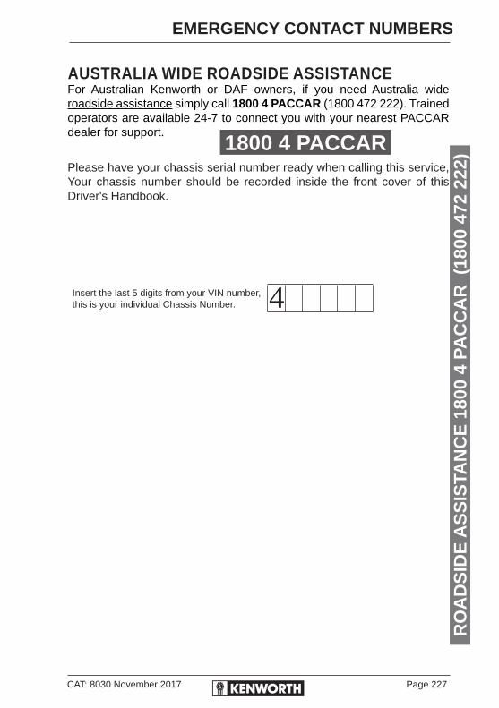
CAT: 8030 November 2017 Page 227
EMERGENCY CONTACT NUMBERS
AUSTRALIA WIDE ROADSIDE ASSISTANCEFor Australian Kenworth or DAF owners, if you need Australia wide roadside assistance simply call 1800 4 PACCAR (1800 472 222). Trained operators are available 24-7 to connect you with your nearest PACCAR dealer for support.
Please have your chassis serial number ready when calling this service, Your chassis number should be recorded inside the front cover of this Driver's Handbook.
Insert the last 5 digits from your VIN number, this is your individual Chassis Number.
RO
AD
SID
E A
SS
ISTA
NC
E 1
800
4 PA
CC
AR
(18
00 4
72 2
22)1800 4 PACCAR
4


SECTION THREEMAINTENANCE & LUBRICATION
SCHEDULES

THE ENVIRONMENTPollution forms a serious threat to the environment. In order to keep pollution to a minimum, you are recommended to take the following measures:
• Never discharge used oil, hydraulic fluids, or coolants via drains, sewers or onto the soil. Such practices are not only illegal, but also contribute considerably to environmental pollution.
• Used oils, coolants and hydraulic fluids should be returned to the appointed organisation, for re-use. Ensure all used liquids are separated.• Ensure your vehicle is regularly maintained. A correctly maintained vehicle contributes to maximum fuel saving and reduces pollutant exhaust gases.

CH
AN
GE
OF
AD
DR
ES
S/O
WN
ER
SH
IPP
leas
e as
sist
Ken
wor
th T
ruck
s to
kee
p ve
hicl
e re
cord
s up
to d
ate.
If y
ou c
hang
e an
y of
you
r de
tails
(i.
e. tr
adin
g na
me
or a
ddre
ss) o
r sub
sequ
ently
sel
l thi
s ve
hicl
e, p
leas
e co
mpl
ete
and
retu
rn th
is fo
rm
to th
e ad
dres
s on
the
reve
rse.
Thi
s no
tifica
tion
is im
porta
nt e
ven
afte
r the
orig
inal
veh
icle
war
rant
y in
ca
se K
enw
orth
nee
d to
con
tact
you
.
NO
TIC
E O
F N
AM
E/A
DD
RE
SS
OW
NE
RS
HIP
DE
TAIL
S
Nam
e/A
ddre
ss C
hang
e N
ew O
wne
r:
Dat
e O
wne
rshi
p C
hang
ed:
......
......
......
......
......
(Del
ete
not a
pplic
able
)
Bus
ines
s N
ame:
....
......
......
......
......
......
......
......
......
......
......
......
......
......
......
......
......
......
......
......
......
......
AB
N:
......
......
......
......
......
......
......
......
......
......
......
......
......
......
......
......
......
......
......
......
......
......
......
......
...
Title
Mr/
Mrs
/Ms:
....
......
......
......
......
......
......
.....
Ow
ner’s
Nam
e: .
......
......
......
......
......
......
......
......
......
Add
ress
: ...
......
......
......
......
......
......
......
......
.....
Tow
n: .
......
......
......
......
......
......
......
......
......
......
......
....
Sta
te:
......
......
......
......
......
......
......
......
......
......
.P
ostc
ode:
....
......
......
......
......
......
......
......
......
......
......
Pho
ne N
o: .
......
......
......
......
......
......
......
......
....
VIN
(P
rodu
ct S
eria
l No)
: ...
......
......
......
......
......
......
...
Tear along perforation
Tear along perforation
Tear
alo
ng p
erfo
ratio
n

Attention: C
ustomer
Service
Kenw
orthTrucks
Reply
Paid
64847B
AYS
WAT
ER
VIC
3153
Deliv
ery
Ad
dress:
64C
anterburyR
oadB
AS
YS
WAT
ER
VIC
3153
No
stamp
requiredif posted
inA
ustralia

CAT: 8030 November 2017 Page 233
LUBRICATION SCHEDULE
INTRODUCTIONThis Service Section is provided to help keep your vehicle operating at optimum performance. It should be used with the Operating Instructions and Preventive Maintenance Sections of this handbook, and in conjunction with your Electronic Customised Maintenance Manual supplied with your vehicle. The service schedules specified are for all models of Kenworth trucks in operation throughout Australia, New Zealand and Papua New Guinea.
Contents PageChange of Address/Ownership . . . . . . . . . . . . . . . . . . . . . . . . 233
Warranty Questions . . . . . . . . . . . . . . . . . . . . . . . . . . . . . . . . 234
Kenworth Dealer Network . . . . . . . . . . . . . . . . . . . . . . . . . . . 238
Owner’s Responsibility . . . . . . . . . . . . . . . . . . . . . . . . . . . . . . 238
Master Lubrication Chart . . . . . . . . . . . . . . . . . . . . . . . . . . . . 239
A Service Intervals - 10,000 kilometers . . . . . . . . . . . . . . . . . 240
B Service Intervals - 20,000 kilometers . . . . . . . . . . . . . . . . 242
C Service Intervals - 40,000 kilometers . . . . . . . . . . . . . . . . 243
X Service Intervals - >40,000 kilometers . . . . . . . . . . . . . . . . 246
Chassis Lubrication Points . . . . . . . . . . . . . . . . . . . . . . . . . . . 248
Castrol Master Lubrication Chart . . . . . . . . . . . . . . . . . . . . . . 253
Lubrication and Fluid Capacities . . . . . . . . . . . . . . . . . . . . . . 255
Service Intervals . . . . . . . . . . . . . . . . . . . . . . . . . . . . . . . . . . . 257
Maintenance Service Records . . . . . . . . . . . . . . . . . . . . . . . . 265
First Service Inspection Record . . . . . . . . . . . . . . . . . . . . . . . 269
Service Inspection Records . . . . . . . . . . . . . . . . . . . . . . . . . . 271
CHANGE OF ADDRESS/OWNERSHIPPlease assist Kenworth Trucks to keep vehicle records up to date. If you change any of your details (i.e. trading name or address) or subsequently sell this vehicle, please complete and return the pre-paid card provided on the page opposite to the reply paid address on the reverse. This notification is important even after expiration of the original vehicle warranty in case Kenworth need to contact you.
Page 234 CAT: 8030 November 2017
LUBRICATION SCHEDULE
WARRANTY QUESTIONSThis section will assist you to understand the terms of the warranty provided with your new vehicle. The following are some of the more frequently asked questions:1. Q. Who is an authorised Kenworth Trucks dealer?
A. There are 56 authorised Kenworth Trucks/PACCAR Parts dealers throughout Australia, New Zealand and Papua New Guinea.
2. Q. What parts are covered under Kenworth Trucks warranty?
A. Any part, other than engines manufactured by and for PACCAR, fitted to your vehicle at the Kenworth factory is covered by warranty. This includes all original equipment supplied by manufacturers including Eaton, Meritor, Dana.
3. Q. How do I go about obtaining warranty service?
A. It is the responsibility of the selling Kenworth dealer to provide warranty service. You can therefore take your vehicle to that dealer whenever service is required. However, if it is not possible for you to take your vehicle to the selling dealer you may take your vehicle to any other authorised Kenworth dealer. The owner and vehicle identification details recorded on the inside front cover of this handbook are required by the authorised Kenworth servicing dealer in connection with the provision of warranty service. Therefore, you should present this handbook to the authorised Kenworth service dealer whenever you request warranty service.
The 10,000 kilometre/First Service is a free service (see Question 10, page 236 & Service Inspection Records page 269) and should be carried out by an authorised Kenworth service dealer.
4. Q. What should I do if emergency warranty service is required, and an authorised Kenworth service dealer is not available?
A. If, in an emergency, a repair, replacement or adjustment covered by the New Vehicle Warranty is required to enable your vehicle to be operated safely, and it is not practicable for you to have that service performed by an authorised Kenworth service dealer, the service, but only to the extent that it is necessary to enable your vehicle to be operated safely, may be performed by any other qualified service technician or repairer. A warranty claim for the reasonable cost of such service may be made through your authorised Kenworth service dealer. When such emergency

CAT: 8030 November 2017 Page 235
LUBRICATION SCHEDULE
service has been performed by someone other than an authorised Kenworth service dealer, you should take your vehicle to an authorised Kenworth dealer for inspection and/or the completion of any required warranty service as soon as possible.
5. Q. What should I do if my vehicle becomes unsafe or inoperative as a result of a defect which is covered by the New Vehicle Warranty?
A. If, as a result of a defect which is covered by the New Vehicle Warranty, your vehicle cannot be driven or is unsafe to drive, you should contact the nearest authorised Kenworth service dealer as soon as possible, and arrange for that dealer to carry out the required warranty service.
6. Q. Will I have to pay for any costs or expenses in connection with the provision of warranty service?
A. All parts and labour used and supplied in carrying out warranty service at the premises of an authorised Kenworth servicing dealer are free of charge (except consumables such as oil and filters). Whenever warranty service is to be carried out by an authorised Kenworth service dealer, it is your responsibility to deliver your vehicle to the service dealer’s premises. If, as a result of a defect which is covered by the New Vehicle Warranty, your vehicle cannot be safely driven, you may arrange for the nearest authorised Kenworth service dealer to carry out the required warranty service on site. Remember, if in doubt, call your authorised Kenworth dealer.
7. Q. Is damage or injury, loss of time, inconvenience, commercial or other direct or indirect loss covered by the New Vehicle Warranty?
A. No, these items are not covered. The New Vehicle Warranty covers only the repair, replacement or adjustment at the service dealer’s premises of those parts of your vehicle which are found to be defective in materials or workmanship during the warranty period. No other types of claim for compensation of whatever nature will be recognised.
Page 236 CAT: 8030 November 2017
LUBRICATION SCHEDULE
8. Q. Are my tyres covered by New Vehicle Warranty?
A. The tyres fitted to your vehicle are covered by a separate warranty provided by the tyre manufacturer. Your authorised Kenworth service dealer will assist you by discussing any queries you may have with respect to the tyre with the tyre manufacturer’s representatives.
9. Q. Are PACCAR/Kenworth Truck parts and accessories covered by warranties?
A. If you purchase a PACCAR supplied part or accessory from an authorised Kenworth parts dealer, it will be warranted by that dealer under the PACCAR Parts warranty against defects in materials or workmanship for a period of 12 months from the date on which you purchased it. Where the part or accessory has been installed in a vehicle by an authorised Kenworth service dealer, the cost of labour will also be covered for a period of 12 months from the date of installation.
Warranty on parts fitted as part of a warranty repair expires 12 months from the vehicle's date in service.
10. Q. Will I have to pay maintenance costs during the warranty period?
A. Maintenance costs, since they do not arise from defects in materials or workmanship, are not covered by the New Vehicle Warranty. However, the scheduled 10,000 kilometre/First Service specified in this handbook is free of charge (except for any lubricants used), provided your vehicle has been operated under normal conditions, and no modification (other than a modification made by, or at, the direction of Kenworth) has been made to your vehicle which adversely affects the performance and/or compliance of your vehicle. The Maintenance Schedules in this handbook specify the minimum maintenance requirements for your vehicle operating under normal conditions.

CAT: 8030 November 2017 Page 237
LUBRICATION SCHEDULE
If you operate under extreme conditions, your vehicle may require more frequent maintenance services. See your servicing dealer for advice on these matters.
The maintenance items, except where they are required as a result of defects in materials or workmanship, for which you will be required to pay, include:
• Engine tune-up (includes replacing injectors/injector nozzles).
• Replacement of all filters.
• Cleaning or flushing of fuel, AdBlue, cooling, engine, transmission, differential or power steering systems - after 10,000 kilometres.
• Adding to, or replacing, lubricants.
• Adjustments to drive belts, transmission, clutch, parking brake etc.
• Replacing wiper blade rubber elements.
• Wheel balancing after 10,000 kilometres.
• Wheel alignment (front and rear).
• De-dusting or de-glazing of brake linings or pads after 10,000 kilometres.
• Brake lining wear or damage.
• Battery recharging.
• Paint, bright metal finish and trim, due to normal deterioration.
• Door adjustments.
• Glass or channel adjustments after 90 days.
• Body rattles, squeaks and general tightening of bolts, fastenings and fittings after 90 days.
• Chipped glass or breakage.
• Torn or damaged floor mats or carpets.

Page 238 CAT: 8030 November 2017
LUBRICATION SCHEDULE
KENWORTH DEALER NETWORKKenworth trucks are sold and supported by a national network of dealers. Each has been selected for their experience and commitment to supporting the truck industry. Each one is required to carry set levels of spare parts, and maintain a trained service facility. You can be assured that all Kenworth trucks are supported by Australia’s most professional truck dealer network.
OWNER’S RESPONSIBILITY
MAINTENANCE SERVICES ARE THE OWNER’S RESPONSIBILITYIt is the owner’s responsibility to ensure that all scheduled maintenance services specified on the vouchers in this book are carried out at the recommended intervals. The owner should also retain evidence that these services have been performed. It is important to note that any claims made during the warranty period will not qualify under the terms of the New Vehicle Warranty if resulting from failure to carry out proper maintenance services. We therefore strongly recommend that your vehicle be serviced by an authorised Kenworth service dealer. These dealerships are equipped with facilities, trained personnel and Kenworth parts to service and maintain your vehicle to factory recommendations.

CAT: 8030 November 2017 Page 239
LUBRICATION SCHEDULE
MASTER LUBRICATION CHART
(ALL KENWORTH TRUCKS)SAE 15W-40, API CJ-4 Lubricant may be used providing it meets specifications. Schedule service intervals more frequently for severe operational conditions.
Do not mix lubricants of different brands or types. If brand or type of lubricant is changed, the unit must be drained and flushed out prior to refill.Do not mix coolants of different brands or types. If brand new coolant is used, or the type of coolant is changed, the cooling system must be drained and flushed prior to refill.For special service requirements, consult your lubricant supplier. In all cases, the lubricant supplier assumes full responsibility for the performance of the product and for product and patent liability.
The Preventive Maintenance Program really starts with the daily checks that you perform. These checks are itemised in Section 1, in the Driver’s Checklists on pages 21-26.
The service schedules starting on page 240 cover the periodic maintenance which must be performed on your vehicle. Service intervals are for normal on-highway operations.
The chart below shows equivalent service intervals for normal off-highway and mining operations.
PERIODIC MAINTENANCEOn-Highway Off-Highway & Local
CarriersOpen Cut Mining
Severe ServiceEnclosed Pit Mining
10,000 km 250 hours 125 hours
20,000 km 500 hours 250 hours
40,000 km 1,000 hours 500 hours
For First Service details, refer to the Maintenance and Lubrication Schedule.

Page 240 CAT: 8030 November 2017
LUBRICATION SCHEDULE
A-SERVICE: 10,000 KILOMETRESEngine lubricating oil & oil filter change intervals are not listed here. Refer to the engine operating manual for recommendations.
1. CHECK OIL LEVELS and top up as necessary: Engine, rear carrier(s), front drive axle, steering gear, power steering reservoir, tilt-cab pump and oil lubricated wheel bearings.
2. ENGINE OIL FILTER (full-flow): Refer to engine manufacturer’s specifications.
3. FUEL FILTER: Drain, clean and refill, or replace as equipped.4. CRANKCASE BREATHER: Clean.
5. ENGINE COOLANT: Check level and top up as necessary.
Top up engine coolant with an approved pre-mix of engine coolant. Do not top up with water only as this will deplete the engine coolant concentration. This can lead to serious engine damage.
6. DRIVE BELTS: Check condition and adjust tension as necessary.
7. STEERING U-JOINTS: Check for wear on nylon bushes.
8. CHASSIS LUBRICATION: Lubricate all fittings (EXCEPT nylon type steering U-joints), slack adjusters and rear suspension.
9. STEERING LINKAGE: IMPORTANT! — Check ALL connections for free play and wear. Check tie-rod for straightness. Check draglink tube clamp for tightness and interference. Check power steering hydraulic tubes for leaks or chafing.
10. STEERING DRIVELINE: Check torque on U-joint pinch bolt and nut: 75-80 Nm lubricated. Check steering for excessive play, and adjust as necessary.
11. FRONT AXLE: Check bushings and spindles, U-bolt torques, steering arms & tie rod ends (lubricate as required), spring shackle & hanger brackets, spring pins (lubricate as required). Check spring leaves for damage and general inspection for wear.
12. FRONT SUSPENSION: Lubricate spring shackles & fittings. Ensure grease purges from both sides of shackle pin.
13. REAR AXLE: Check drive axle oil and filters, check axle breathers are clear.
14. WHEEL BEARINGS & SEALS: Check oil lubricated steer axle bearings, top up as required, check seal integrity .

CAT: 8030 November 2017 Page 241
LUBRICATION SCHEDULE
15. BRAKES: Check brake lining adjustment as required. Check brake pedal free play, hose fittings for damage and leaks. Camshafts to be lubricated sparingly.
16. SLACK ADJUSTERS: Check push-rod travel, and adjust as necessary see page 157. Lubricate sparingly with high-temperature brake grease.
17 WHEELS & TYRES: Check condition of all wheels and tyres.
18. FUEL, OIL & AIR TANKS: Clean fuel tank breathers and drain sediment from all tanks. Check all tanks for fluid and air leaks.
19. ADBLUE SYSTEM: Check fittings on pump, tank and dosing unit for leaks, ensure filler area is clean and free of any contaminants.
20. DRIVESHAFT U-JOINTS & CENTRE BEARING(S): Check for wear before lubricating with chassis lube. Ensure U-joint is purged to ensure grease gets to all four points of the cross. Check centre bearings.
21. BATTERIES: Check the following:
a) Electrolyte level and specific gravity.b) Battery box condition, and tray.
c) Condition of all equipment mounted under battery box. Look for acid marks on top of air tank, etc.
d) Battery box drain tube. Check for blockage, build-up and routing.
e) Check batteries for cracks or damage.
22. CAB/SLEEPER/HOOD: Check general condition of cab components, interior and exterior, including windscreen and doors.
23. HVAC AIR FILTER: Check, clean or replace filter element as required.24. CAB TILT SYSTEM: Lubricate latch assembly with silicone spray
lubricant. Check for hydraulic leaks around all fittings, tighten any loose fittings and top up reservoir as necessary. Hydraulic leaks should be repaired by your authorised Kenworth dealer.
25. DRIVE AXLE SPRINGS/REAR SUSPENSION: Lubricate every 10,000 km.
26. EXHAUST SYSTEM: Inspect system for leaks.
27. RADIATOR HOSES & WATER PUMP: Inspect hoses for routing, chafing and leaks. Check all hose fittings for tightness.
28. CLUTCH: Check clutch pedal for free play and operation. Check and lubricate release bearing, cross-shaft bushings and control linkage.
29. AIR SYSTEM SILENCERS: Check and clean as necessary see page 216.

Page 242 CAT: 8030 November 2017
LUBRICATION SCHEDULE
B-SERVICE: 20,000 KILOMETRESCarry out all of A Service checks plus the following:
1. CHANGE ENGINE OIL & FILTER (BYPASS): Refer to engine manufacturer’s specifications.
2. ENGINE COOLANT: Check the level and condition of coolant. Add coolant if required.
3. AIR INTAKE INTEGRITY: All intake components and interfaces on the “clean side” to be examined.
a) Condition and sealing of rubber elbows and hump hoses.
b) Clamp tensions and orientation.
c) Material integrity of intake pipes, including welds on fabricated parts.
d) Other sealing and mating surfaces as applicable.
e) General pipe clearances to other components.
4. TRANSMISSIONS/AXLES: Check oil levels and top up as necessary.
5. ENGINE EMERGENCY SHUTDOWN: Each shutdown system is engine specific. Consult your engine manufacturer’s manual to become familiar with your engine’s system.
6. AIR COMPRESSOR AIR CLEANER: Inspect element (if fitted) and replace as necessary.
7. CLUTCH BRAKE OPERATION: Check and adjust as necessary.
8. FRONT & REAR BRAKES - DRUM & DISC: Check for wear and scoring, Service & Spring chambers, check operation and condition.
9. SPRING BRAKES: Check emergency operation of Spring Brakes
10. POWER STEERING: Check hoses and fittings for tightness and wear.11. BATTERIES: Check battery hold-downs.
12. WHEEL NUTS: Check tightness of all wheel nuts.
13. ENGINE MOUNTING BOLTS: Check torque of engine mounting bracket to bellhousing bolts.
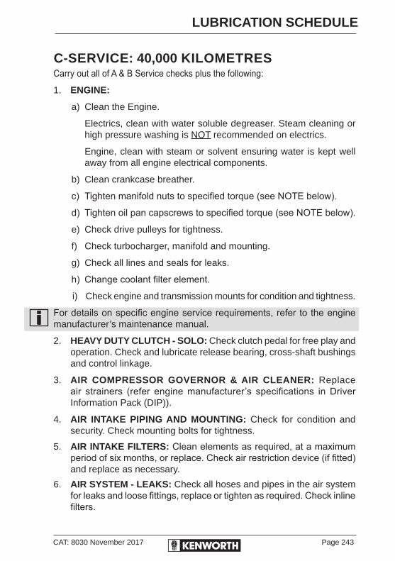
CAT: 8030 November 2017 Page 243
LUBRICATION SCHEDULE
C-SERVICE: 40,000 KILOMETRESCarry out all of A & B Service checks plus the following:
1. ENGINE:
a) Clean the Engine.
Electrics, clean with water soluble degreaser. Steam cleaning or high pressure washing is NOT recommended on electrics.
Engine, clean with steam or solvent ensuring water is kept well away from all engine electrical components.
b) Clean crankcase breather.
c) Tighten manifold nuts to specified torque (see NOTE below).
d) Tighten oil pan capscrews to specified torque (see NOTE below).
e) Check drive pulleys for tightness.
f) Check turbocharger, manifold and mounting.
g) Check all lines and seals for leaks.
h) Change coolant filter element.
i) Check engine and transmission mounts for condition and tightness.
For details on specific engine service requirements, refer to the engine manufacturer’s maintenance manual.
2. HEAVY DUTY CLUTCH - SOLO: Check clutch pedal for free play and operation. Check and lubricate release bearing, cross-shaft bushings and control linkage.
3. AIR COMPRESSOR GOVERNOR & AIR CLEANER: Replace air strainers (refer engine manufacturer’s specifications in Driver Information Pack (DIP)).
4. AIR INTAKE PIPING AND MOUNTING: Check for condition and security. Check mounting bolts for tightness.
5. AIR INTAKE FILTERS: Clean elements as required, at a maximum period of six months, or replace. Check air restriction device (if fitted) and replace as necessary.
6. AIR SYSTEM - LEAKS: Check all hoses and pipes in the air system for leaks and loose fittings, replace or tighten as required. Check inline filters.
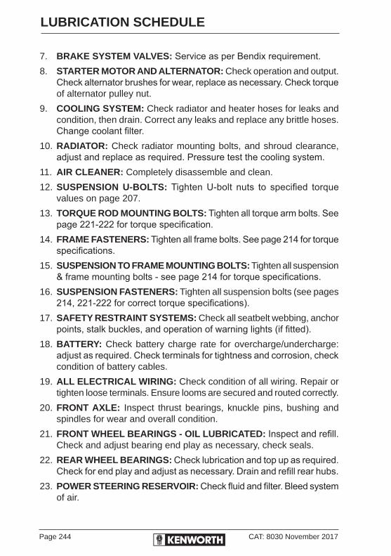
Page 244 CAT: 8030 November 2017
LUBRICATION SCHEDULE
7. BRAKE SYSTEM VALVES: Service as per Bendix requirement.8. STARTER MOTOR AND ALTERNATOR: Check operation and output.
Check alternator brushes for wear, replace as necessary. Check torque of alternator pulley nut.
9. COOLING SYSTEM: Check radiator and heater hoses for leaks and condition, then drain. Correct any leaks and replace any brittle hoses.Change coolant filter.
10. RADIATOR: Check radiator mounting bolts, and shroud clearance, adjust and replace as required. Pressure test the cooling system.
11. AIR CLEANER: Completely disassemble and clean.
12. SUSPENSION U-BOLTS: Tighten U-bolt nuts to specified torque values on page 207.
13. TORQUE ROD MOUNTING BOLTS: Tighten all torque arm bolts. See page 221-222 for torque specification.
14. FRAME FASTENERS: Tighten all frame bolts. See page 214 for torque specifications.
15. SUSPENSION TO FRAME MOUNTING BOLTS: Tighten all suspension & frame mounting bolts - see page 214 for torque specifications.
16. SUSPENSION FASTENERS: Tighten all suspension bolts (see pages 214, 221-222 for correct torque specifications).
17. SAFETY RESTRAINT SYSTEMS: Check all seatbelt webbing, anchor points, stalk buckles, and operation of warning lights (if fitted).
18. BATTERY: Check battery charge rate for overcharge/undercharge: adjust as required. Check terminals for tightness and corrosion, check condition of battery cables.
19. ALL ELECTRICAL WIRING: Check condition of all wiring. Repair or tighten loose terminals. Ensure looms are secured and routed correctly.
20. FRONT AXLE: Inspect thrust bearings, knuckle pins, bushing and spindles for wear and overall condition.
21. FRONT WHEEL BEARINGS - OIL LUBRICATED: Inspect and refill. Check and adjust bearing end play as necessary, check seals.
22. REAR WHEEL BEARINGS: Check lubrication and top up as required. Check for end play and adjust as necessary. Drain and refill rear hubs.
23. POWER STEERING RESERVOIR: Check fluid and filter. Bleed system of air.

CAT: 8030 November 2017 Page 245
LUBRICATION SCHEDULE
24. PARKING (SPRING) BRAKES: Inspect breathers, release bolts, clamp rings and bolts, mounting studs and air lines for condition and tightness.
25. FRONT-END ALIGNMENT: As required, dependent on tyre wear.27. REAR AXLES - OIL AND FILTER CHANGES: Drain lubricant while
warm. Flush out each unit with clean flushing oil. Refill. Check all drain and filler plugs for tightness. Refer to Maintenance and Lubrication Schedules pages 239-264.

Page 246 CAT: 8030 November 2017
LUBRICATION SCHEDULE
X-SERVICE (GREATER THAN 40,000 KLM INTERVALS)Carry out the following service items at the recommended intervals listed below:
1. POWER STEERING GEAR: Drain, flush and replace fluid at 160,000km, 4,000 hours or 36 months, whichever occurs first.
2. CAB TILT SYSTEM (K200): Drain, flush and replace fluid at 160,000km, 4,000 hours or 36 months, whichever occurs first.
3. CR 2000 AIR DRYER: Change filter and seals at 300,000 km, 7,500 hours or 12 months, whichever occurs first.
4. REAR AXLES, MINERAL OIL: On-highway 80,000km, Off-highway 40,000km. Oil and filter changes - drain lubricant while warm. Flush out each unit with clean flushing oil and refill. Inspect all drain and filler plugs for tightness. Under severe service: 40,000 km, 500 hours or 24 months, whichever occurs first.
5. REAR AXLES, SYNTHETIC OIL: On-highway 400,000km, Off-highway 160,000km. Oil and filter changes - take oil samples for analysis at 80,000km. Drain lubricant while warm. Flush out each unit with clean flushing oil and refill. Inspect all drain and filler plugs for tightness. Under severe service: 160,000 km, 2,000 hours or 18 months, whichever occurs first.
6. SISU REAR AXLES, MINERAL OIL: Drain and replace oil and filter at 60,000km - drain lubricant while warm. Flush out each unit with clean flushing oil and refill. Inspect all drain and filler plugs for tightness. As per SISU Service Recommendation SR13009.
7. SISU REAR AXLES, SYNTHETIC OIL: Drain and replace oil at 160,000 km, 4,000 hours or 24 months, whichever occurs first. Take oil samples for analysis at 40,000km
8. TRANSMISSION, (Incl. TRANSFER CASE) MINERAL OIL: On-highway 80,000km, off-highway 40,000km. Oil and filter changes: Drain lubricant while warm. Flush out each unit with clean flushing oil and refill. Inspect all drain and filler plugs for tightness. Under severe service: 40,000 km, 500 hours or 24 months, whichever occurs first.
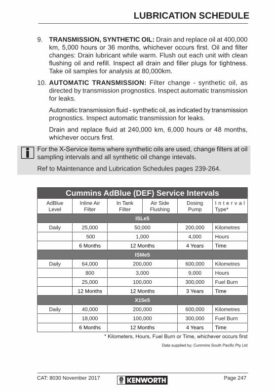
CAT: 8030 November 2017 Page 247
LUBRICATION SCHEDULE
9. TRANSMISSION, SYNTHETIC OIL: Drain and replace oil at 400,000 km, 5,000 hours or 36 months, whichever occurs first. Oil and filter changes: Drain lubricant while warm. Flush out each unit with clean flushing oil and refill. Inspect all drain and filler plugs for tightness. Take oil samples for analysis at 80,000km.
10. AUTOMATIC TRANSMISSION: Filter change - synthetic oil, as directed by transmission prognostics. Inspect automatic transmission for leaks.
Automatic transmission fluid - synthetic oil, as indicated by transmission prognostics. Inspect automatic transmission for leaks.
Drain and replace fluid at 240,000 km, 6,000 hours or 48 months, whichever occurs first.
For the X-Service items where synthetic oils are used, change filters at oil sampling intervals and all synthetic oil change intevals.
Ref to Maintenance and Lubrication Schedules pages 239-264.
Cummins AdBlue (DEF) Service IntervalsAdBlueLevel
Inline AirFilter
In TankFilter
Air SideFlushing
DosingPump
I n t e r v a l Type*
ISLe5
Daily 25,000 50,000 200,000 Kilometres
500 1,000 4,000 Hours
6 Months 12 Months 4 Years Time
ISMe5
Daily 64,000 200,000 600,000 Kilometres
800 3,000 9,000 Hours
25,000 100,000 300,000 Fuel Burn
12 Months 12 Months 3 Years Time
X15e5
Daily 40,000 200,000 600,000 Kilometres
18,000 100,000 300,000 Fuel Burn
6 Months 12 Months 4 Years Time
* Kilometers, Hours, Fuel Burn or Time, whichever occurs firstData supplied by; Cummins South Pacific Pty Ltd

Page 248 CAT: 8030 November 2017
CHASSIS LUBRICATION POINTS
K200 SHOWN - SEE PAGE 250 FOR LEGEND
28
9
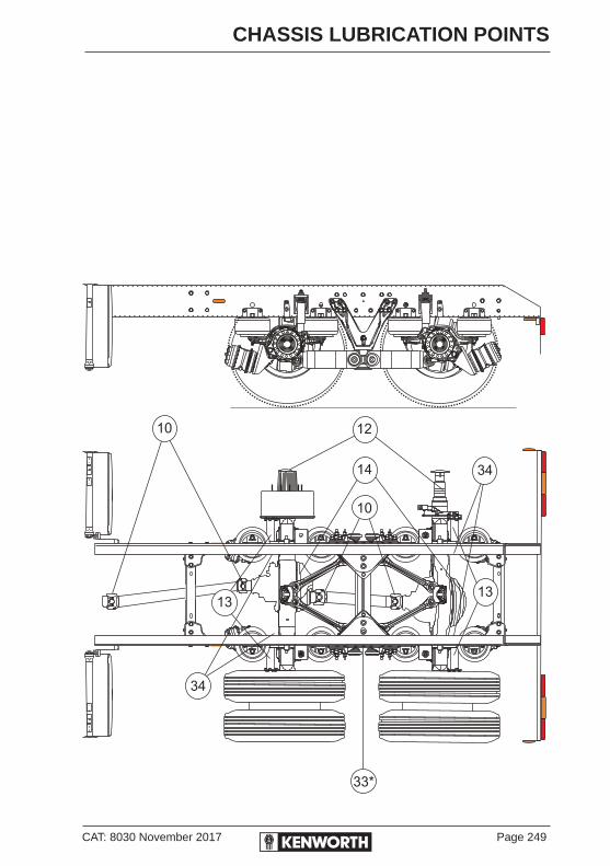
CAT: 8030 November 2017 Page 249
CHASSIS LUBRICATION POINTS

Page 250 CAT: 8030 November 2017
CHASSIS LUBRICATION POINTS
COE & CONV CHASSIS LUBRICATION POINTSKey# ITEM .................................................................................... Lube1.* K200 - CAB TILT PIVOTS (one each side) .............................. CL CONVENTIONAL - HOOD PIVOTS (one each side) ......................................................................... CL2. POWER STEERING GEAR/RESERVOIR Refer to the Engine/Steering Gear Manufacturer’s Manuals for change intervals Change fluid & filter Ross (integral)** or Sheppard (integral)** .............................. ATF Grease fitting provided in housing trunion ................................ CL (lubricate by hand NOT by pressure gun) Sector Shaft & Input Shaft ........................................................ CL 3. ENGINE COOLANT Check level .............................................EC Check coolant concentrate .......................................................EC Replace filter, Pressure test cooling system .............................EC Drain and replace coolant .......................................................EC4. STEERING U-JOINTS (one fitting each end) ........................... CL 5. DRAG LINK (one fitting each end) ........................................... CL 6.* STEERING SLIP JOINT ........................................................... CL 7.* FRONT BRAKE CAMSHAFT (lubricate sparingly, one fitting each side) ................................BG8. TIE ROD ENDS (one fitting each side) .................................... CL 9. MAIN & AUX TRANSMISSION MANUAL TRANSMISSIONS Check .......................................................................................EO Drain & refill (except synthetic) .................................................EO 20918/22918 Series AUTOSHIFT, ULTRASHIFT & ULTRASHIFT PLUS TRANSMISSIONS - Check ......................................................SO Drain & Refill (Dependant on Oil Sample) ................................SO AUTOMATIC (Allison MD & HD Series) Check ..................................................................................... STF Drain & refill ............................................................................ STF Replace Filter ......................................................................... STF10. DRIVESHAFTS Slip Joint, U-Joints
(one fitted each end) ........................................................... CL 11*. TRANSFER CASE See lube specifications .............................EO12. REAR WHEEL BEARINGS ..................................................... GO

CAT: 8030 November 2017 Page 251
CHASSIS LUBRICATION POINTS
Key# ITEM .................................................................................... Lube13. REAR BRAKE CAMSHAFTS (Lube sparingly) one fitting each brake ....................................BG 14. REAR AXLES Mineral oil Check oil level ......................................................................... GO Drain, flush & refill ................................................................... GO REAR AXLES Synthetic oil Check .......................................................................................SO Drain & refill (Dependent on Oil Sample) .................................SO15*. FIFTH WHEEL .......................................................................... CL 16. SPRING PINS (one fitting each side) ....................................... CL 17*. FAN DRIVE (inspect & drain) ........................................................18*. FRONT SLACK ADJUSTERS (lube sparingly) .........................................................................BG19. KING PIN (two fittings each side) ............................................. CL20. FRONT WHEEL BEARINGS Oil lubricated ........................................................................... GO21. SPRING SHACKLE PINS (two fittings each side/end of spring) ........................................ CL22. ENGINE LUBRICATING OIL Check oil level ..........................................................................EO Change oil, fuel & coolant filters ...............................................EO (Refer to engine manual for intervals)23*. CLUTCH PEDAL SHAFT ......................................................... CL24*. CLUTCH LINKAGE .................................................................. CL25*. CLUTCH RELEASE BEARING Remove Trans inspection plate for access ............................... BB26*. CLUTCH CROSS SHAFT (one fitting each side) ............................................................... CL27*. ECA CLUTCH (with UltraShift) Lube ........................................SO28. DOOR WEATHERSTRIP .........................................................SL29. DOOR LOCK CYLINDERS ....................................................... LL30. DOOR HINGES ........................................................................EO31. DOOR LATCHES & STRIKER PLATES ...................................PG32. CENTRE BEARING (if fitted) ................................................... CL33*. SUSPENSION KW6-60A .......................................................... CL34. REAR SLACK ADJUSTERS(lube sparingly) ............................BG
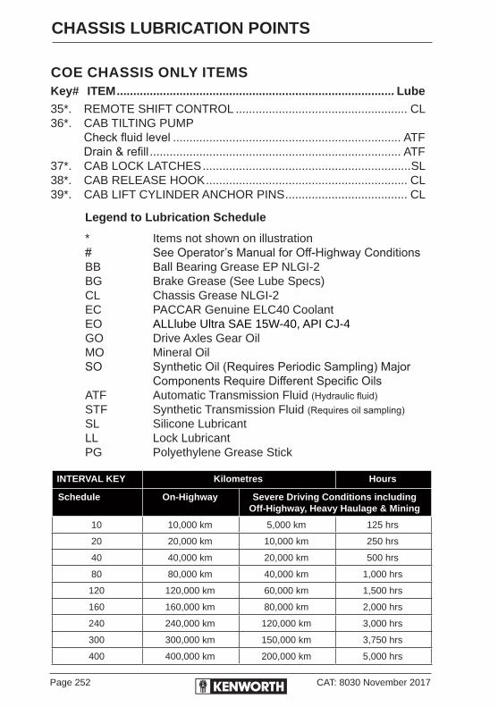
Page 252 CAT: 8030 November 2017
CHASSIS LUBRICATION POINTS
COE CHASSIS ONLY ITEMSKey# ITEM .................................................................................... Lube
35*. REMOTE SHIFT CONTROL .................................................... CL36*. CAB TILTING PUMP Check fluid level ..................................................................... ATF Drain & refill ............................................................................ ATF37*. CAB LOCK LATCHES ...............................................................SL38*. CAB RELEASE HOOK ............................................................. CL39*. CAB LIFT CYLINDER ANCHOR PINS ..................................... CL
Legend to Lubrication Schedule
* Items not shown on illustration# See Operator’s Manual for Off-Highway ConditionsBB Ball Bearing Grease EP NLGI-2BG Brake Grease (See Lube Specs)CL Chassis Grease NLGI-2EC PACCAR Genuine ELC40 CoolantEO ALLlube Ultra SAE 15W-40, API CJ-4GO Drive Axles Gear OilMO Mineral OilSO Synthetic Oil (Requires Periodic Sampling) Major Components Require Different Specific OilsATF Automatic Transmission Fluid (Hydraulic fluid)STF Synthetic Transmission Fluid (Requires oil sampling)SL Silicone LubricantLL Lock LubricantPG Polyethylene Grease Stick
INTERVAL KEY Kilometres Hours
Schedule On-Highway Severe Driving Conditions includingOff-Highway, Heavy Haulage & Mining
10 10,000 km 5,000 km 125 hrs
20 20,000 km 10,000 km 250 hrs
40 40,000 km 20,000 km 500 hrs
80 80,000 km 40,000 km 1,000 hrs
120 120,000 km 60,000 km 1,500 hrs
160 160,000 km 80,000 km 2,000 hrs
240 240,000 km 120,000 km 3,000 hrs
300 300,000 km 150,000 km 3,750 hrs
400 400,000 km 200,000 km 5,000 hrs

CAT: 8030 November 2017 Page 253
CASTROL MASTER LUBRICATION CHART
ENGINES LUBRICANT CHECK NORMAL SERVICEINTERVAL
Cummins
EGR EngineSCR Engine
Castrol Vecton 15W-40 CJ-4/E9
Meets API CJ-4 SpecificationMeets API CI-4 Specification
DailyRefer to Engine Maintenance Manual for recommended Oil Change Intervals and Filter Service
TRANSMISSION LUBRICATION CHECK NORMAL SERVICEINTERVAL
Eaton/Fuller<18*** Series
Eaton/FullerUltraShift AutoShift & 20918/22918 Series
Castrol TFC 450
Castrol Syntrans 50ERoadranger Lube SAE 50
10,000 km
10,000 km
Oil samples at 80,000 km
DRAIN AND REPLACE:ON-HIGHWAY 80,000 kmOFF-HIGHWAY 40,000 km.Mining and Earthmoving every 500 hours
SYNTHETIC OIL:Drain and refill at 400,000 km or 5,000 hours maximum.
OFF HIGHWAY – Severe service: Refer to OEM’s Service Manuals.
AUTOMATIC TRANSMISSION & CONVERTERS
LUBRICATION CHECK NORMAL SERVICEINTERVAL
ALLISON AUTOMATIC3000 Series Transmissions
Castrol Transynd TES 295 Transmission Fluid
Last run of the day check with the engine
running
DRAIN AND REPLACE OIL:As indicated by transmission prognostics or 240,000km, 3,000hrs or 48 months whichever occurs first.FILTER CHANGE INTERVALAs directed by transmission prognostics or change filter at 120,000 km, 1,500 hrs or 36 months whichever occurs first.
DRIVING AXLES LUBRICATION CHECK NORMAL SERVICEINTERVAL
Meritor
DanaMeritor
Castrol Axle AP 85W-140 Gear Oil
Castrol Syntrax E 80W-140Roadranger Syn Axle
Lube 80W-140
10,000 km
Oil Samples at 80,000 km
On/Off Hwy at 40,000 km
DRAIN AND REPLACE:ON-HIGHWAY80,000 km or every six months, whichever occurs first.OFF-HIGHWAY 40,000 km/500 hours
DRAIN AND REPLACE:ON-HIGHWAY400,000 km or 3 yearsON/OFF-HIGHWAY160,000 km or 1 year
SISU Castrol Axle AP 85W-140 Gear Oil 10,000kmDRAIN AND REPLACE:ON-HIGHWAY 60,000 km2
OFF-HIGHWAY 30,000 km or 375 hours*
Factory fill Mineral Oil. Drain on First Service or 10,000 km whichever comes first. Refill with Synthetic Oil. Drail and refill at 400,000 km Maximum. Sample at 100,000 km.Severe Service: Change at 160,000 km. Sample at 40,000 km.Refer to OEM's Maintenance Manual for suggested service intervals
Synthetic Oil
Mineral Oil
Synthetic Oil1
Mineral Oil
Mineral Oil
1
2
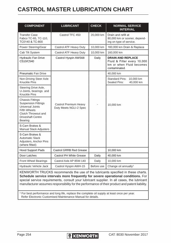
Page 254 CAT: 8030 November 2017
CASTROL MASTER LUBRICATION CHART
COMPONENT LUBRICANT CHECK NORMAL SERVICEINTERVAL
Transfer CaseFabco TC-65, TC-110, TC0140 & TC-800
Castrol TFC 450 20,000 km Drain and refill at 80,000 km or sooner, depend-ing on type of service.
Power Steering/Gear Castrol ATF Heavy Duty 10,000 km 160,000 km Drain & Replace
Cab Tilt System Castrol ATF Heavy Duty 10,000 km 160,000 km
Hydraulic Fan DriveC510/C540
Castrol Hyspin AWS68 Daily DRAIN AND REPLACEFluid & Filter every 10,000 km or when Fluid becomes contaminated.
Pneumatic Fan Drive
Castrol Premium Heavy Duty Meets NGLI-2 Spec
-
40,000 km
Non-Driving Steer Axle Knuckle Pins
Standard Pins: 10,000 km Sealed Pins: 40,000 km
Steering Drive Axle, U-Joints, bearings and Knuckle Pins
10,000 km
Chassis FittingsSuspension FittingsUniversal JointsFifth WheelsClutch Throwout andDriveshaft CentreBearing
S-Cam Brakes & Manual Slack Adjusters
S-Cam Brakes & Automatic Slack Adjusters, Anchor Pins (where fitted)
Hood Support Pads Castrol GRRB Red Grease 10,000 km
Door Latches Castrol PH White Grease Daily 40,000 km
Front Wheel Bearings Castrol Axle AP 85W-140 Daily 10,000 km
Hydraulic Vehicle Jack Castrol Hyspin AWH-15 Before use Change oil annually3
KENWORTH TRUCKS recommends the use of the lubricants specified in these charts. Schedule service intervals more frequently for severe operational conditions. For special service requirements, consult your lubricant supplier. In all cases, the lubricant manufacturer assumes responsibility for the performance of their product and patent liability.
3 For best performance and long life, replace the complete oil supply at least once per year. Refer Electronic Customised Maintenance Manual for details.

CAT: 8030 November 2017 Page 255
LUBRICATION AND FLUID CAPACITIES
Engine Oil K200 T359T359A
T409 T609 T659 T909 C509 C510
Cummins ISLe5 - 26.5 - - - - - -Cummins ISMe5 37.0 37.0 - - - - - -Cummins X15e5 49.2 - 49.2 49.2 49.2 49.2 49.2 -Cummins QSK19 LTA - - - - - - - 68.5Refill quantities include oil filter change
Transmission OilFR9210B - 11.1 - - - - - -FRO12210C - - - - - - -RTOF11909ALL - 13 - - - - - -RTLO12910-AS3 - 13 - - - - - -RTLO12913A - 13 - - - - - -RTO14909-ALL - 12 - - - - - -RTO14910B-DM3 - 12 - - - - - -RTO14910-AS3 - 12 - - - - - -RTLO14913A 13 13 - - - - - -RTLO14918B 13 13 - - - - - -RTLO16910B-DM3 - 13 13 - - - - -RTLO16910-AS3 - 13 13 - - - - -RTLO16913A 13 - 13 13 13 13 13 -RTLO16918B 13 13 13 13 13 13 13 -RTLO16918A-AS3 13 13 13 13 13 13 13 -RTLO18913A 13 - 13 13 13 13 13 -RTLO18918B 13 - 13 13 13 13 13 -RTLO18918A-AS3 13 - 13 13 13 13 13 -RTLO18913A 13 - 13 13 13 13 13 -RTLO18918B 13 - 13 13 13 13 13 -RTLO18918A-AS3 13 - 13 13 13 13 13 -RTLO20918B 13 - 13 13 13 13 13 -RTLO20918A-AS3 13 - 13 13 13 13 13 -RTLO22918B 13 - - 13 13 13 13 13RTLO22918A-AS3 13 - - 13 13 13 13 -FO-14E309ALL-VMS - 13 - - - - - -FO-14E318B-MXP - 13 - - - - - -F0-16E310C-LAS - 13 - - - - - -FO-16E318-MXP - 13 - - - - - -FO-18E318-MXP - - - - - - - -FO-20E318-MXP 13 - 13 13 - - - -FO-22E318B-MXP 13 - - 13 13 13 13 -
plus Remote Filter 0.5 0.5 0.5 0.5 0.5 0.5 0.5 0.5plus Oil Cooler Approx 1.1 ltr of oil per 7 metre run including oil cooler and standard size 10 hose
Auto TransmissionAllison 3000 Series 2” Sump - 16 - - - - - -Allison 3000 Series 4” Sump - 18 - - - - - -Allison H6610/H6620 - - - - - - - 70
T409SAR
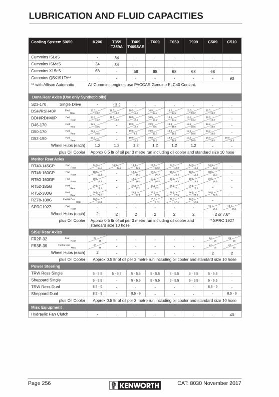
Page 256 CAT: 8030 November 2017
LUBRICATION AND FLUID CAPACITIES
Cooling System 50/50 K200 T359T359A
T409 T609 T659 T909 C509 C510
Cummins ISLe5 - 34 - - - - - -
Cummins ISMe5 34 34 - - - - - -
Cummins X15e5 68 - 58 68 68 68 68 -
Cummins QSK19 LTA** - - - - - - - 90
** with Allison Automatic All Cummins engines use PACCAR Genuine ELC40 Coolant.
Dana Rear Axles (Use only Synthetic oils)
S23-170 Single Drive - 13.2 - - - - - -
DSH/RSH40P Fwd Rear
18.513.2
18.513.2
18.513.2
18.513.2
18.513.2
18.513.2
18.513.2 -
DDH/RDH40P Fwd Rear
18.513.2
18.513.2
18.513.2
18.513.2
18.513.2
18.513.2
18.513.2 -
D46-170 Fwd Rear
19.918.5 - 19.9
18.5 19.9
8.5 19.9
18.5 19.9
18.5 19.9
18.5 -
D50-170 Fwd Rear
19.918.5 - 19.9
8.5 19.9
18.5 19.9
18.5 19.9
18.5 19.9
18.5 -
D52-190 Fwd Rear
19.918.5 - 19.9
18.5 19.9
18.5 19.9
18.5 19.9
18.5 19.9
18.5 19.9
18.5
Wheel Hubs (each) 1.2 1.2 1.2 1.2 1.2 1.2 - -
plus Oil Cooler Approx 0.5 ltr of oil per 3 metre run including oil cooler and standard size 10 hose
Meritor Rear Axles
RT40-145GP Fwd Rear
14.312.2
14.312.2
14.312.2
14.312.2
14.312.2
14.312.2
14.312.2 -
RT46-160GP Fwd Rear
18.516.3 - 18.5
16.318.5
16.318.5
16.318.5
16.318.5
16.3 -
RT50-160GP Fwd Rear
18.516.3 - 18.5
16.318.5
16.318.5
16.318.5
16.318.5
16.3 -
RT52-185G Fwd Rear
26.517.1 - 26.5
17.126.5
17.126.5
17.126.5
17.1 - -
RT52-380G Fwd Rear
26.527.5 - 26.5
27.526.5
27.526.5
27.526.5
27.526.5
27.5 -
RZ78-188G Fwd & Cntr Rear
26.517.1 - - 26.5
17.126.5
17.126.5
17.1 - -
SPRC1927 Fwd Rear - - - - - - 15.1
15.115.1
15.1
Wheel Hubs (each) 2 2 2 2 2 2 2 or 7.6*
plus Oil Cooler Approx 0.5 ltr of oil per 3 metre run including oil cooler and standard size 10 hose
* SPRC 1927
SISU Rear Axles
FR2P-32 Fwd Rear
24 18 - - - - - 24
1824
18
FR3P-39 Fwd & Cntr Rear
24 18 - - - - - 24
1824
18
Wheel Hubs (each) 2 - - - - - 2 2
plus Oil Cooler Approx 0.5 ltr of oil per 3 metre run including oil cooler and standard size 10 hose
Power Steering
TRW Ross Single 5 - 5.5 5 - 5.5 5 - 5.5 5 - 5.5 5 - 5.5 5 - 5.5 5 - 5.5 -
Sheppard Single 5 - 5.5 - 5 - 5.5 5 - 5.5 5 - 5.5 5 - 5.5 5 - 5.5 -
TRW Ross Dual 8.5 - 9 - - - - - 8.5 - 9 -
Sheppard Dual 8.5 - 9 - 8.5 - 9 - - - - 8.5 - 9
plus Oil Cooler Approx 0.5 ltr of oil per 3 metre run including oil cooler and standard size 10 hose
Misc Eqiupment
Hydraulic Fan Clutch - - - - - - - 40
T409SAR
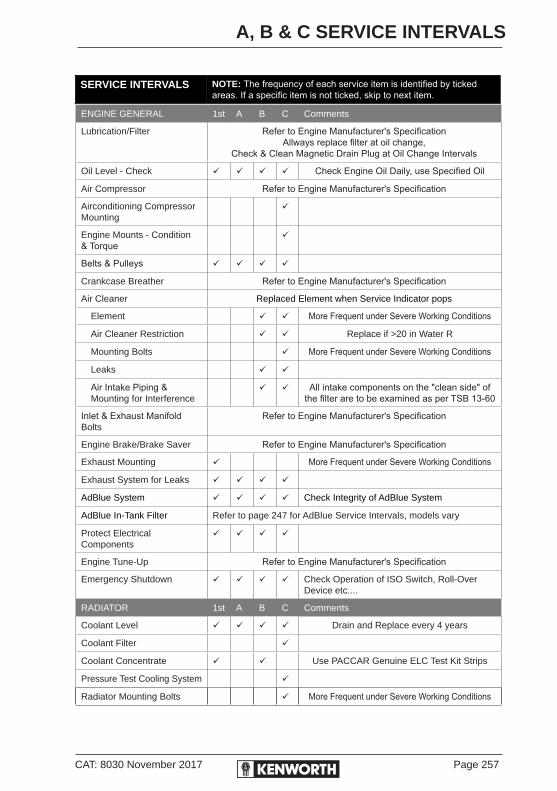
CAT: 8030 November 2017 Page 257
A, B & C SERVICE INTERVALS
SERVICE INTERVALS NOTE: The frequency of each service item is identified by ticked areas. If a specific item is not ticked, skip to next item.
ENGINE GENERAL 1st A B C Comments
Lubrication/Filter Refer to Engine Manufacturer's SpecificationAllways replace filter at oil change,
Check & Clean Magnetic Drain Plug at Oil Change Intervals
Oil Level - Check Check Engine Oil Daily, use Specified Oil
Air Compressor Refer to Engine Manufacturer's Specification
Airconditioning Compressor Mounting
Engine Mounts - Condition & Torque
Belts & Pulleys
Crankcase Breather Refer to Engine Manufacturer's Specification
Air Cleaner Replaced Element when Service Indicator pops
Element More Frequent under Severe Working Conditions
Air Cleaner Restriction Replace if >20 in Water R
Mounting Bolts More Frequent under Severe Working Conditions
Leaks
Air Intake Piping & Mounting for Interference
All intake components on the "clean side" of the filter are to be examined as per TSB 13-60
Inlet & Exhaust Manifold Bolts
Refer to Engine Manufacturer's Specification
Engine Brake/Brake Saver Refer to Engine Manufacturer's Specification
Exhaust Mounting More Frequent under Severe Working Conditions
Exhaust System for Leaks
AdBlue System Check Integrity of AdBlue System
AdBlue In-Tank Filter Refer to page 247 for AdBlue Service Intervals, models vary
Protect Electrical Components
Engine Tune-Up Refer to Engine Manufacturer's Specification
Emergency Shutdown Check Operation of ISO Switch, Roll-Over Device etc....
RADIATOR 1st A B C Comments
Coolant Level Drain and Replace every 4 years
Coolant Filter
Coolant Concentrate Use PACCAR Genuine ELC Test Kit Strips
Pressure Test Cooling System
Radiator Mounting Bolts More Frequent under Severe Working Conditions

Page 258 CAT: 8030 November 2017
A, B & C SERVICE INTERVALS
SERVICE INTERVALS NOTE: The frequency of each service item is identified by ticked areas. If a specific item is not ticked, skip to next item.
RADIATOR Continued 1st A B C Comments
Fan Shroud Clearance Or when adjusting fan belts with new tensioner
Check Coolant Pump for Leaks and Play
Radiator Hoses
CLUTCH 1st A B C Comments
Release Bearing Requires Extended fittings.Lubricate as per manufacturer’s recommen-
dation.
Clutch Pedal Free Play & Operation
Clutch Brake Operation
Wet Clutch System Used with UltraShift Plus Transmissions
Linkage & Shafts
Clutch Linkage
Pedal Shaft
Cross Shaft
Remote Shaft
TRANSMISSIONS 1st A B C Comments
Main Transmission Manual
Oil - Mineral Drain & Replace Transmission Oil every 80,000 km. Check & Clean Drain Plug
Filter Replace Filter every 80,000km
Oil - Synthetic Eaton/Fuller AutoShift and 20918, 22918 Series: Drain mineral oil on First Service or 10,000km, whichever comes first. Refill with Synthetic oil. Take oil samples to determine correct oil change interval & change filter at 80,000km. Change oil at 400,000km maximum.For severe service, refer to OEM's Service Manuals.
UltraShift Plus Drain mineral oil on First Service or 10,000 km, whichever comes first. Refill with Synthetic oil. Take oil samples to determine correct oil change interval & change filter at 80,000km. Change oil at 400,000 km maximum. For severe service, refer to OEM's Service Manuals.
Main Transmission Auto
Auto Trans Fluid Drain & Replace Oil: As indicated by transmission prognostics OR 240,000km, 6,000 hrs or 48 months whichever occurs first.
Filter Filter Change Interval: As indicated by transmission prognostics OR 120,000km, 3,000 hrs or 36 months whichever occurs first.
Transfer Case/Auxiliary Drain & Replace Transmission Oil every 80,000km - Replace filter at oil change

CAT: 8030 November 2017 Page 259
A, B & C SERVICE INTERVALS
SERVICE INTERVALS NOTE: The frequency of each service item is identified by ticked areas. If a specific item is not ticked, skip to next item.
POWER STEERING 1st A B C Comments
Sector Shaft More Frequent under Severe Working Conditions
Steering U-Joints (1 each side) - Check
More Frequent under Severe Working Conditions
Steering Shaft Splines & Slip Joints - Lubricate
More Frequent under Severe Working Conditions
Drag Link / Pitman Arm Check clamp torque
Steering Pinch Bolts
Steering Wheel Free Play & Centralise
Check and adjust if required
Steering Box Mounting Bracket & Bolts
Check torque of Bolts
Hoses & Fittings Check all hoses for damage
Operation & Damage Check for damage and operation of system
Reservoir - Fluid Level Drain & Replace Power Steering Fluid every 160,000km
Reservoir - Filter, Bleed System of Air
Replace Filter every 80,000km
FRONT WHEEL BEARINGS 1st A B C Comments
Oil Lubricated More Frequent under Severe Working Conditions
Wheel Bearings - Check End Play
More Frequent under Severe Working Conditions
FRONT AXLES 1st A B C Comments
Spring Shackle & Hanger Brackets - Lubricate
More Frequent under Severe Working Conditions
Shackle Pins & Bushes Check for Wear, lubricate
Spring Leaves for Damage Clean off dirt and debris, lightly lubricateMore Frequent under Severe Working Conditions
Spring Pins - Lubricate More Frequent under Severe Working Conditions
King Pins, Bushings, Thrust Bearings & Spindles
More Frequent under Severe Working Conditions
Suspension U-Bolt Torques More Frequent under Severe Working Conditions
General Inspection for Wear More Frequent under Severe Working Conditions
Steering Arms & Tie Rod Arms (inc Tie Rod Ends) (1 each side) - Lubricate
More Frequent under Severe Working Conditions
Front Axle Steering Stops
Front End Alignment As Required Dependent on Tyrewear

Page 260 CAT: 8030 November 2017
A, B & C SERVICE INTERVALS
SERVICE INTERVALS NOTE: The frequency of each service item is identified by ticked areas. If a specific item is not ticked, skip to next item.
DRIVE SHAFTS 1st A B C Comments
U-Joints - Lubricate More Frequent under Severe Working Conditions
Slip Joint More Frequent under Severe Working Conditions
Centre Bearing (if fitted) Non-Greasable Sealed Units
REAR AXLES & FRONT DRIVE AXLES
1st A B C Comments
Drain Mineral Oil: Drain & Replace Oil every 80,000 km - 40,000 km under Severe Service Conditions. Check & clean drain plugsSynthetic Oil: Drain mineral oil on First Service or 10,000 km, whichever comes first. Refill with Synthetic oil. Take oil samples to determine correct oil change interval & change filter at 80,000 km. Change oil at 400,000 km maximum. For severe service, refer to OEM's Service Manuals. Replace filter, check & clean drain plugs with oil change.
Drive Axle Oil Filters
Rear Axle Breathers - Clear
REAR SUSPENSION 1st A B C Comments
Rear Suspension Alignment As Required Dependent on Tyrewear
General Inspection for Wear More Frequent under Severe Working Conditions
KW6-60A More Frequent under Severe Working Conditions
REAR WHEEL BEARINGS 1st A B C Comments
Check Play & Adjust More Frequent under Severe Working Conditions
Drain & Refill Rear Hubs Drain & Replace Oil every 80,000 km - 40,000 km under Severe Service Conditions
CHASSIS 1st A B C Comments
All Chassis Lube/Grease Points More Frequent under Severe Working Conditions
Chassis Bolts/Frame Fasteners More Frequent under Severe Working Conditions
Suspension to Frame Bolts More Frequent under Severe Working Conditions
Cab & Sleeper Mounting Points
More Frequent under Severe Working Conditions
Engine Mounting Bolts More Frequent under Severe Working Conditions
Transmission Mounting Bolts More Frequent under Severe Working Conditions
Suspension U-Bolt Torques More Frequent under Severe Working Conditions - Refer U-Bolt Torques
Torque Rod Mounting Bolts More Frequent under Severe Working Conditions - Refer U-Frame Torques
Hood Pivots, Alignment & Clearance
Air & Electrical (Routing)

CAT: 8030 November 2017 Page 261
A, B & C SERVICE INTERVALS
SERVICE INTERVALS NOTE: The frequency of each service item is identified by ticked areas. If a specific item is not ticked, skip to next item.
CHASSIS Continued 1st A B C Comments
Air Dryers & Moisture Ejectors
Air Dryer Filters Remove & Service Air Filter at 300,000 km or 12 Months, whichever comes first
Air & Fuel Tanks
Air Valve Silencers More Frequent under Severe Working Conditions
Drain Water from Fuel & Air Tanks
Air Tank Check Valve
Fuel Tank Mounting
CAB LIFT EQUIPMENT (COE only)
1st A B C Comments
Anchor pins
Pump Reservoir Make sure reservoir filled to top with fluid
Cab Tilt Pins (1 each side)
Cab Lock Latches (1 each side) Check Safety Hook
Check operation and engagement of components
Cab Raised Safety Latch
Cab Tilt Pump Operation & Check all fittings for Leaks
Tighten any loose fittings
FIFTH WHEEL 1st A B C Comments
Check & Lubricate
BATTERY & ELECTRICS 1st A B C Comments
Alternator/Charging System
Visual Inspection/Loose Connections
Remove & Inspect Brushes Replace worn brushes as required
Output Voltage:.........Volts Check Every Service - Normal 13.8V - 14.2V
Battery Electrolyte Level
Clean & Tighten Terminals, Connections & Earth
Signs of Overcharging /Undercharging
Load Test Batteries Check Every Six Months
Hold Down & Battery Box Mounting Bolts
Wiring for Chafing/Loose Terminals

Page 262 CAT: 8030 November 2017
A, B & C SERVICE INTERVALS
SERVICE INTERVALS NOTE: The frequency of each service item is identified by ticked areas. If a specific item is not ticked, skip to next item.
BATTERY & ELECTRICS Continued
1st A B C Comments
Cranking System
Visual Inspection/Loose Connections
Starter Draw:.............Volts Check Every Service
Wiring for Chafing/Loose Terminals
Operation of Lights & Instruments
Accessories i.e. Heater/ Airconditioner, Radio's etc...
BRAKES FRONT & REAR 1st A B C Comments
Adjustment
Wheel Seals
Brakes: Linings Remaining (replace if required)
Drum Condition: Check
Emergency Operation of Spring Brakes
Air Pressure Build up Time Recorded in Minutes
Governed Air Pressure Recorded in kPa
Air Pressure Drop - Brakes not Applied
Air Pressure Drop - Brakes Applied
Brake Pedal Free Play
Hoses/Fittings for Damage & Leaks
Camshafts (lubricate sparingly)
Slack Adjusters (lubricate sparingly)
BRAKES TREADLE 1st A B C Comments
Hinge & Roller
WHEELS & TYRES 1st A B C Comments
Wheel Nuts as Required
Cracks & Loose Wheel Lugs

CAT: 8030 November 2017 Page 263
A, B & C SERVICE INTERVALS
SERVICE INTERVALS NOTE: The frequency of each service item is identified by ticked areas. If a specific item is not ticked, skip to next item.
WHEELS & TYRES Continued
1st A B C Comments
Missing Valve Caps & Stem Locks
Tightness of all wheel nuts
Daily and Weekly checks, see pages 23 & 26Wheels & Tyres Inspection
Tyre Pressure & Uneven Tyre Wear
Air Pressure Adjusted to: Recorded in kPa
CABS, DOORS, WINDOWS & ANCILLARIES
1st A B C Comments
Glass for Cracks & Scratches
Window Operation Mechanism
Cab & Sleeper Panel/joints Check no exhaust leaks enter the cab area
Interior Condition/Appear-ance
Seats Condition/Mounting Bolts
Safety Restraint & Anchor Points
HVAC System Check no exhaust leaks enter the cab area
HVAC Air Filter More Frequent under Severe Working Conditions
Floor Mats
Door Panels
Headlining
Sleeper
Dash/Console
Covers
Mirrors
Horns, Air & Electric
Door Weatherstripping
Door Lock - Lubricate
Door Hinges - Lubricate
Door Latches & Striker Plate - Lubricate
Windscreen Washer Bottle & Operation, Wiper Blades

Page 264 CAT: 8030 November 2017
A, B & C SERVICE INTERVALS
SERVICE INTERVALS NOTE: The frequency of each service item is identified by ticked areas. If a specific item is not ticked, skip to next item.
MISCELLANEOUS 1st A B C Comments
CR2000 Air Filter & Seals At 300,000 km or 12 Months, whichever comes first
Fuel Filters/Water Separators
Accelerator Linkage (if applicable Manual Engines)
ROAD TEST VEHICLE 1st A B C Comments
Steering/Steering Play
Shifting
Brakes
Engine Operation (Noise, Surging, Black Smoke)
Throttle Operation
Air Seat Operation
Seat Belts
Cab & Sleeper Heater/Air Conditioner (if fitted)
Radio/Antenna/CD Player.CB Radio(s)
Instruments & Gauges
Headlights High/Low, Tail, Indicators & Stop Lamps
Speedometer/Odometer
Tachometer
Oil Pressures - Engine, Transmission & Axles
Engine Temperature
All Other Instruments & Gauges
Instrument Illumination
Cabin Interior Lights
ABS Warning
Low Air/Brake Pressure Warning Devices
Hydraulic Vehicle Jack Check fluid level before each use, change oil annually
UNDER SEVERE DRIVING CONDITIONS, MORE FREQUENT MAINTENANCE REQUIREDPlease refer to "Maintenance Schedule Under Severe Driving Conditions"
THESE MINIMUM RECOMMENDED SERVICES COVER ALL MODELS AND OPTIONS WHERE APPLICABLEThis schedule does not cover all items, this schedule should be read in conjunction with your Customised Maintenance Manual.
CAT: 8030 November 2017 Page 265
SERVICE INSPECTION RECORDS
MAINTENANCE SERVICE RECORDThe remainder of this book contains a separate record for each of the scheduled maintenance services recommended for vehicles operating under normal conditions. Printed on each voucher is a list of all the items requiring attention for that particular service. As each service is performed and the record removed, the following service record is readily visible to remind you when the next service is due. For recommended service under severe conditions including off highway, heavy haulage and mining refer to page 252.
The sequence of service with Cummins Installed is as follows:First 10,000km (First Service) will be performed without cost for labour by the selling dealer. This replaces the first A-Service.Subsequent scheduled service Intervals are at 10,000 kilometers thereafter, at 20,000km a B-Service, 30,000km an A-Service and 40,000km a C-Service following the sequence A-B-A-C, the second C-Service at 80,000km.
X-Service are all intervals greater than 40,000km and need to be carried out at the times shown on page 246.
What the owner should doWhen a service is due, according to the time or distance interval, the owner should present this voucher book to an authorised Kenworth service dealer as an authority to have the items listed attended to. After the service is completed, the owner should ensure the validation record is stamped and signed by the servicing dealer. This is important as it will enhance the value of the vehicle whenever resale is contemplated.
What the servicing dealer has to doYour service dealer must attend to all items listed for the particular service, and see that both copies of the validation record are signed. Tear out the perforated top copy and keep with dealership file. The second copy remains in this handbook. All operations listed on the service records should be carried out following the procedures set out in the appropriate current Maintenance and Lubrication Schedules.


SECTION FOURSERVICE RECORDS


FIRST SERVICE INSPECTION RECORDPLEASE USE BLOCK LETTERS
Chassis No: .......................... Model: .................................. Kilometres: ........................... Date Inspected: ...................
Owner: ..................................................................................... Servicing Dealer: ....................................................................
Owner's Address: ..........................................................................................................................................................................
Mechanic to inspect, make adjustments, tighten, correct or add fluids on all operations listed.Consult applicable service information for adjustments and specification.
Tick = OK A = Adjust R = Repair
# Action Service Item Result 1 Change Engine Oil *
2 Change Transmission Oil * (Allison Automatic - Do Not Drain) See Reverse - Note
3 Change Auxiliary Transmission Oil *(Synthetic at customers request) 4 Change Forward Rear Axle Oil * (Synthetic at customers request) 5 Change Rear Rear Axle Oil * (Synthetic at customers request) 6 Change Engine Oil Filter
7 Change Fuel Filter
8 Change Coolant Filter
9 Change Transmission Filter
10 Change Rear Axle filter11 Change Power Steering Oil Filter & Gasket12 Check Air Cleaner Element(s) are Sealing Correctly/Condition
13 Check Engine Oil Level After Starting
14 Check or Repair Any Oil, Fuel, Coolant, Hydraulic & Air System Leaks15 Check AdBlue Filler Area is Clean, Check Fittings for Leaks
16 Check/Record Radiator Coolant Level & Condition See Reverse
17 Check/Record Battery Electrolyte Level & Tighten Terminals See Reverse
18 Check Oil Level in Cab Tilt Cylinder Pump Reservoir
19 Check Power Steering Oil Levels
20 Check & Adjust Front Wheel Bearing End Play (if Outside Specs) .001” - .005”
21 Check & Adjust Front Axle Steering Stops (if Tyres Rubbing)
22 Check & Adjust Front and Rear Brakes
23 Lubricate/Purge Grease Points, Suspension, Driveline & Strg Components24 Check Steering Components including King Pins
25 Check Tension Chassis Bolts
26 Check Tension Cab & Sleeper Mount Bolts27 Check Hood Bolts (Tension) Hood Alignment (Adjust)
28 Check/Re-Tension U-Bolts Refer Page 207
29 Check Tension Rear Suspension Bolts
30 Check Tension Steering Drag Link Pinch Bolts
31 Check Tension Engine Mount Bolts - Front & Rear32 Check Tension Radiator Mount Bolts - inc Upper Stabiliser Alignment
33 Centralise Steering Wheel - in Straight Ahead Position
34 Top Up Windscreen Washer Bottle & Test Washers35 Drain Air Tanks - Remind Operator of Daily Routine If Moisture Present
36 Check Routing Electrical Wiring & Air Lines, Eliminate Chafing37 Check Routing Coolant, CAC & Air Intake Hoses, Eliminate Chafing38 Check Tension Radiator Hoses with Torque Wrench 50 - 60 in-lbs (6 - 7 Nm)
39 Check Tension C.A.C. Hoses with Torque Wrench 105 - 115 in-lbs (11.8 - 13 Nm)
40 Check/Lube Door Locks, Latches & Wedge Blocks41 Check Operation of Lights, Gauges, Wipers & Horns42 Check All Appointments & Accessories for Correct Operation43 Check & Adjust Clutch & Operation44 Check & Adjust Belts & Idler Pulleys Alignment, Fan/Cowl Clearance45 Clean Down Vehicle Report Any Damage
46 Road Test & Report Carry Out Any Additional Work
* Fill in accordance with OEM’s Recommendations - Do Not Overfill Components Specified With Synthetic Oils are to be Installed at this Interval, See Reverse
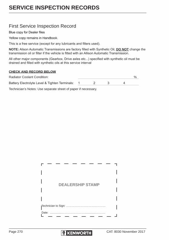
Page 270 CAT: 8030 November 2017
SERVICE INSPECTION RECORDS
First Service Inspection RecordBlue copy for Dealer files
Yellow copy remains in Handbook.
This is a free service (except for any lubricants and filters used).
NOTE: Alison Automatic Transmissions are factory filled with Synthetic Oil, DO NOT change the transmission oil or filter if the vehicle is fitted with an Allison Automatic Transmission.
All other major components (Gearbox, Drive axles etc...) specified with synthetic oil must be drained and filled with synthetic oils at this service interval
CHECK AND RECORD BELOW
Radiator Coolant Condition: %
Battery Electrolyte Level & Tighten Terminals: 1 2 3 4
Technician’s Notes: Use separate sheet of paper if necessary.
DEALERSHIP STAMP
Technician to Sign: ……………………………………
Date: ...............……………………...............……….

CAT: 8030 November 2017 Page 271
SERVICE INSPECTION RECORDS
B-SERVICE - 20,000 KM SERVICE INSPECTION RECORDCarry out all of the A Service Items - Plus the following items:
Check Boxes - Tick = OK A = Adjust R = Repair
Change Engine Oil* Power Steering
Engine Oil Filter By Pass* Batteries, Battery Hold-downs & Mounting
Engine Coolant Level - Check Level Wheel Nuts
Engine Coolant Condition -Test Road Test Vehicle
Air Intake Integrity, Check Element/Restriction During Road Test:
Transmissions & Axles (Oil Levels & Filters) Check Engine Operation
Engine Emergency Shutdown Check Clutch, Transmission & Driveline Operation
Air Compressor Air Cleaner Check Exhaust Brake Operation
Clutch Brake Operation Check Braking Performance
Front & Rear Brakes - Drums & Disc Check Steering Operation
Service & Spring Brake Chambers - Drums & Disc
Air Seat & Restraints Operation
Spring Brakes - Check Operation Check Operation of all Lights, Wipers, Horn & Instrumentation
See pages 240-242 in the current Driver’s Handbook for full description of work to be carried out during this inspection. For Technician’s comments, please use reverse side.
* Refer to Original Equipment Manufacturers for their recommended service intervals
DEALERSHIP STAMP
Technician to Sign: ……………………………………
Date: ...............……………………...............……….

Page 272 CAT: 8030 November 2017
SERVICE INSPECTION RECORDS
B-Service Inspection RecordTechnician’s Notes: Use separate sheet of paper if necessary.

CAT: 8030 November 2017 Page 273
SERVICE INSPECTION RECORDS
A-SERVICE - 30,000 KM SERVICE INSPECTION RECORDCheck Boxes - Tick = OK A = Adjust R = Repair
Check Oil Levels* Electrical Systems & Routing
Engine Full Flow Oil Filter* Batteries, see reverse
Fuel Filter* Cab/Sleeper/Hood - General
Crankcase Breather Cab Tilt System (if fitted)
Engine Coolant Rear Axle Springs/Suspension
Drive Belts & Pulleys Exhaust System - Mounting & Leaks
Steering U-Joints Radiator Hoses/Coolant Pump
Full Chassis Lubrication Clutch
Chassis/Frame - General Check 5th Wheel - Lube & Mounting
Power Steering Driveline U-Joints /Linkages/Fluid Level
Air System Silencers
Front Axle HVAC System - Air filter
Front Suspension Road Test Vehicle
Rear Axle (Drive Axles) During Road Test:
Wheel Bearing & Seals Check Engine Operation
Brakes – Check & Adjust Check Clutch, Transmission & Driveline Operation
Slack Adjusters Check Exhaust Brake Operation
Wheels & Tyres Check Braking Performance
Fuel, Oil & Air Tanks Check Steering Operation
Check AdBlue Tank for Leaks & Cleanliness Air Seat & Restraints Operation
Driveshaft U-Joints & Centre Bearing(s) Check Operation of all Lights, Wipers, Horn & Instrumentation
See pages 240-241 in the current Driver’s Handbook for full description of work to be carried out during this inspection. For Technician’s comments, please use reverse side.
* Refer to Original Equipment Manufacturers for their recommended service intervals
DEALERSHIP STAMP
Technician to Sign: ……………………………………
Date: ...............……………………...............……….

Page 274 CAT: 8030 November 2017
SERVICE INSPECTION RECORDS
A-Service Inspection RecordTechnician’s Notes: Use separate sheet of paper if necessary.
CHECK AND RECORD BELOW
Radiator Coolant Condition: %
Battery Electrolyte Level & Tighten Terminals: 1 2 3 4
Technician’s Notes: Use separate sheet of paper if necessary.

CAT: 8030 November 2017 Page 275
SERVICE INSPECTION RECORDS
C-SERVICE - 40,000 KM SERVICE INSPECTION RECORDCarry out all of the A & B Service Items - Plus the following items:
Check Boxes - Tick = OK A = Adjust R = Repair
Engine* Safety Restraint System (185)
Transmission Oil & Filter Change* Battery Charge Rate & Terminals, Check for Corrosion
Transfer Case Oil & Filter Change* Electrical Wiring System & Routing
Clutch Front Axle
Air Compressor Governor & Air Cleaner Front & Rear Wheel Bearings & Seals
Air Intake Piping & Mounting Steering Fluid Level/Reservoir
Air Intake Filters Parking (Spring) Brakes
Air System – Leaks & Check Air System Inline Filters
Front Axle Alignment
Brake System Valves Rear Axles Oil & Filter
Starter Motor & Alternator Road Test Vehicle
Cooling System & Filter During Road Test:
Radiator Checks Check Engine Operation
Air Cleaner Element/Restriction Check Clutch, Transmission & Driveline Operation
Suspension U-Bolts Check Exhaust Brake Operation
Torque Rod Mounting Bolts Check Braking Performance
Frame Fasteners Check Steering Operation
Suspension to Frame Mounting Bolts Air Seat and Restraints Operation
Suspension Fasteners Check Operation of all Lights, Wipers, Horn & Instrumentation
See pages 240-245 in the current Driver’s Handbook for full description of work to be carried out during this inspection. For Technician’s comments, please use reverse side.
* Refer to Original Equipment Manufacturers for their recommended service intervals
DEALERSHIP STAMP
Technician to Sign: ……………………………………
Date: ...............……………………...............……….

Page 276 CAT: 8030 November 2017
SERVICE INSPECTION RECORDS
C-Service Inspection RecordTechnician’s Notes: Use separate sheet of paper if necessary.

CAT: 8030 November 2017 Page 277
SERVICE INSPECTION RECORDS
A-SERVICE - 50,000 KM SERVICE INSPECTION RECORDCheck Boxes - Tick = OK A = Adjust R = Repair
Check Oil Levels* Electrical Systems & Routing
Engine Full Flow Oil Filter* Batteries, see reverse
Fuel Filter* Cab/Sleeper/Hood - General
Crankcase Breather Cab Tilt System (if fitted)
Engine Coolant Rear Axle Springs/Suspension
Drive Belts & Pulleys Exhaust System - Mounting & Leaks
Steering U-Joints Radiator Hoses/Coolant Pump
Full Chassis Lubrication Clutch
Chassis/Frame - General Check 5th Wheel - Lube & Mounting
Power Steering Driveline U-Joints /Linkages/Fluid Level
Air System Silencers
Front Axle HVAC System - Air filter
Front Suspension Road Test Vehicle
Rear Axle (Drive Axles) During Road Test:
Wheel Bearing & Seals Check Engine Operation
Brakes – Check & Adjust Check Clutch, Transmission & Driveline Operation
Slack Adjusters Check Exhaust Brake Operation
Wheels & Tyres Check Braking Performance
Fuel, Oil & Air Tanks Check Steering Operation
Check AdBlue Tank for Leaks & Cleanliness Air Seat & Restraints Operation
Driveshaft U-Joints & Centre Bearing(s) Check Operation of all Lights, Wipers, Horn & Instrumentation
See pages 240-241 in the current Driver’s Handbook for full description of work to be carried out during this inspection. For Technician’s comments, please use reverse side.
* Refer to Original Equipment Manufacturers for their recommended service intervals
DEALERSHIP STAMP
Technician to Sign: ……………………………………
Date: ...............……………………...............……….

Page 278 CAT: 8030 November 2017
SERVICE INSPECTION RECORDS
A-Service Inspection RecordTechnician’s Notes: Use separate sheet of paper if necessary.
CHECK AND RECORD BELOW
Radiator Coolant Condition: %
Battery Electrolyte Level & Tighten Terminals: 1 2 3 4
Technician’s Notes: Use separate sheet of paper if necessary.

CAT: 8030 November 2017 Page 279
SERVICE INSPECTION RECORDS
B-SERVICE - 60,000 KM SERVICE INSPECTION RECORDCarry out all of the A Service Items - Plus the following items:
Check Boxes - Tick = OK A = Adjust R = Repair
Change Engine Oil* Power Steering
Engine Oil Filter By Pass* Batteries, Battery Hold-downs & Mounting
Engine Coolant Level - Check Level Wheel Nuts
Engine Coolant Condition -Test Road Test Vehicle
Air Intake Integrity, Check Element/Restriction During Road Test:
Transmissions & Axles (Oil Levels & Filters) Check Engine Operation
Engine Emergency Shutdown Check Clutch, Transmission & Driveline Operation
Air Compressor Air Cleaner Check Exhaust Brake Operation
Clutch Brake Operation Check Braking Performance
Front & Rear Brakes - Drums & Disc Check Steering Operation
Service & Spring Brake Chambers - Drums & Disc
Air Seat & Restraints Operation
Spring Brakes - Check Operation Check Operation of all Lights, Wipers, Horn & Instrumentation
See pages 240-242 in the current Driver’s Handbook for full description of work to be carried out during this inspection. For Technician’s comments, please use reverse side.
* Refer to Original Equipment Manufacturers for their recommended service intervals
DEALERSHIP STAMP
Technician to Sign: ……………………………………
Date: ...............……………………...............……….

Page 280 CAT: 8030 November 2017
SERVICE INSPECTION RECORDS
B-Service Inspection RecordTechnician’s Notes: Use separate sheet of paper if necessary.
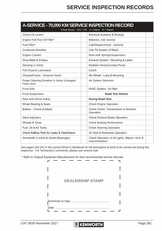
CAT: 8030 November 2017 Page 281
SERVICE INSPECTION RECORDS
A-SERVICE - 70,000 KM SERVICE INSPECTION RECORDCheck Boxes - Tick = OK A = Adjust R = Repair
Check Oil Levels* Electrical Systems & Routing
Engine Full Flow Oil Filter* Batteries, see reverse
Fuel Filter* Cab/Sleeper/Hood - General
Crankcase Breather Cab Tilt System (if fitted)
Engine Coolant Rear Axle Springs/Suspension
Drive Belts & Pulleys Exhaust System - Mounting & Leaks
Steering U-Joints Radiator Hoses/Coolant Pump
Full Chassis Lubrication Clutch
Chassis/Frame - General Check 5th Wheel - Lube & Mounting
Power Steering Driveline U-Joints /Linkages/Fluid Level
Air System Silencers
Front Axle HVAC System - Air filter
Front Suspension Road Test Vehicle
Rear Axle (Drive Axles) During Road Test:
Wheel Bearing & Seals Check Engine Operation
Brakes – Check & Adjust Check Clutch, Transmission & Driveline Operation
Slack Adjusters Check Exhaust Brake Operation
Wheels & Tyres Check Braking Performance
Fuel, Oil & Air Tanks Check Steering Operation
Check AdBlue Tank for Leaks & Cleanliness Air Seat & Restraints Operation
Driveshaft U-Joints & Centre Bearing(s) Check Operation of all Lights, Wipers, Horn & Instrumentation
See pages 240-241 in the current Driver’s Handbook for full description of work to be carried out during this inspection. For Technician’s comments, please use reverse side.
* Refer to Original Equipment Manufacturers for their recommended service intervals
DEALERSHIP STAMP
Technician to Sign: ……………………………………
Date: ...............……………………...............……….

Page 282 CAT: 8030 November 2017
SERVICE INSPECTION RECORDS
A-Service Inspection RecordTechnician’s Notes: Use separate sheet of paper if necessary.
CHECK AND RECORD BELOW
Radiator Coolant Condition: %
Battery Electrolyte Level & Tighten Terminals: 1 2 3 4
Technician’s Notes: Use separate sheet of paper if necessary.

CAT: 8030 November 2017 Page 283
SERVICE INSPECTION RECORDS
C-SERVICE - 80,000 KM SERVICE INSPECTION RECORDCarry out all of the A & B Service Items - Plus the following items:
Check Boxes - Tick = OK A = Adjust R = Repair
Engine* Safety Restraint System (185)
Transmission Oil & Filter Change* Battery Charge Rate & Terminals, Check for Corrosion
Transfer Case Oil & Filter Change* Electrical Wiring System & Routing
Clutch Front Axle
Air Compressor Governor & Air Cleaner Front & Rear Wheel Bearings & Seals
Air Intake Piping & Mounting Steering Fluid Level/Reservoir
Air Intake Filters Parking (Spring) Brakes
Air System – Leaks & Check Air System Inline Filters
Front Axle Alignment
Brake System Valves Rear Axles Oil & Filter
Starter Motor & Alternator Road Test Vehicle
Cooling System & Filter During Road Test:
Radiator Checks Check Engine Operation
Air Cleaner Element/Restriction Check Clutch, Transmission & Driveline Operation
Suspension U-Bolts Check Exhaust Brake Operation
Torque Rod Mounting Bolts Check Braking Performance
Frame Fasteners Check Steering Operation
Suspension to Frame Mounting Bolts Air Seat and Restraints Operation
Suspension Fasteners Check Operation of all Lights, Wipers, Horn & Instrumentation
See pages 240-245 in the current Driver’s Handbook for full description of work to be carried out during this inspection. For Technician’s comments, please use reverse side.
* Refer to Original Equipment Manufacturers for their recommended service intervals
DEALERSHIP STAMP
Technician to Sign: ……………………………………
Date: ...............……………………...............……….
Page 284 CAT: 8030 November 2017
SERVICE INSPECTION RECORDS
C-Service Inspection RecordTechnician’s Notes: Use separate sheet of paper if necessary.

CAT: 8030 November 2017 Page 285
SERVICE INSPECTION RECORDS
A-SERVICE - 90,000 KM SERVICE INSPECTION RECORDCheck Boxes - Tick = OK A = Adjust R = Repair
Check Oil Levels* Electrical Systems & Routing
Engine Full Flow Oil Filter* Batteries, see reverse
Fuel Filter* Cab/Sleeper/Hood - General
Crankcase Breather Cab Tilt System (if fitted)
Engine Coolant Rear Axle Springs/Suspension
Drive Belts & Pulleys Exhaust System - Mounting & Leaks
Steering U-Joints Radiator Hoses/Coolant Pump
Full Chassis Lubrication Clutch
Chassis/Frame - General Check 5th Wheel - Lube & Mounting
Power Steering Driveline U-Joints /Linkages/Fluid Level
Air System Silencers
Front Axle HVAC System - Air filter
Front Suspension Road Test Vehicle
Rear Axle (Drive Axles) During Road Test:
Wheel Bearing & Seals Check Engine Operation
Brakes – Check & Adjust Check Clutch, Transmission & Driveline Operation
Slack Adjusters Check Exhaust Brake Operation
Wheels & Tyres Check Braking Performance
Fuel, Oil & Air Tanks Check Steering Operation
Check AdBlue Tank for Leaks & Cleanliness Air Seat & Restraints Operation
Driveshaft U-Joints & Centre Bearing(s) Check Operation of all Lights, Wipers, Horn & Instrumentation
See pages 240-241 in the current Driver’s Handbook for full description of work to be carried out during this inspection. For Technician’s comments, please use reverse side.
* Refer to Original Equipment Manufacturers for their recommended service intervals
DEALERSHIP STAMP
Technician to Sign: ……………………………………
Date: ...............……………………...............……….

Page 286 CAT: 8030 November 2017
SERVICE INSPECTION RECORDS
A-Service Inspection RecordTechnician’s Notes: Use separate sheet of paper if necessary.
CHECK AND RECORD BELOW
Radiator Coolant Condition: %
Battery Electrolyte Level & Tighten Terminals: 1 2 3 4
Technician’s Notes: Use separate sheet of paper if necessary.
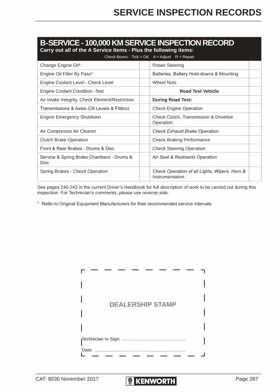
CAT: 8030 November 2017 Page 287
SERVICE INSPECTION RECORDS
B-SERVICE - 100,000 KM SERVICE INSPECTION RECORDCarry out all of the A Service Items - Plus the following items:
Check Boxes - Tick = OK A = Adjust R = Repair
Change Engine Oil* Power Steering
Engine Oil Filter By Pass* Batteries, Battery Hold-downs & Mounting
Engine Coolant Level - Check Level Wheel Nuts
Engine Coolant Condition -Test Road Test Vehicle
Air Intake Integrity, Check Element/Restriction During Road Test:
Transmissions & Axles (Oil Levels & Filters) Check Engine Operation
Engine Emergency Shutdown Check Clutch, Transmission & Driveline Operation
Air Compressor Air Cleaner Check Exhaust Brake Operation
Clutch Brake Operation Check Braking Performance
Front & Rear Brakes - Drums & Disc Check Steering Operation
Service & Spring Brake Chambers - Drums & Disc
Air Seat & Restraints Operation
Spring Brakes - Check Operation Check Operation of all Lights, Wipers, Horn & Instrumentation
See pages 240-242 in the current Driver’s Handbook for full description of work to be carried out during this inspection. For Technician’s comments, please use reverse side.
* Refer to Original Equipment Manufacturers for their recommended service intervals
DEALERSHIP STAMP
Technician to Sign: ……………………………………
Date: ...............……………………...............……….

Page 288 CAT: 8030 November 2017
SERVICE INSPECTION RECORDS
B-Service Inspection RecordTechnician’s Notes: Use separate sheet of paper if necessary.
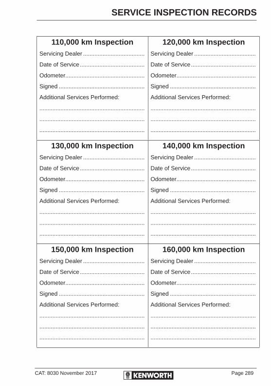
CAT: 8030 November 2017 Page 289
SERVICE INSPECTION RECORDS
110,000 km InspectionServicing Dealer ......................................
Date of Service ........................................
Odometer.................................................
Signed .....................................................
Additional Services Performed:
.................................................................
.................................................................
.................................................................
120,000 km InspectionServicing Dealer ......................................
Date of Service ........................................
Odometer.................................................
Signed .....................................................
Additional Services Performed:
.................................................................
.................................................................
.................................................................
130,000 km InspectionServicing Dealer ......................................
Date of Service ........................................
Odometer.................................................
Signed .....................................................
Additional Services Performed:
.................................................................
.................................................................
.................................................................
140,000 km InspectionServicing Dealer ......................................
Date of Service ........................................
Odometer.................................................
Signed .....................................................
Additional Services Performed:
.................................................................
.................................................................
.................................................................
150,000 km InspectionServicing Dealer ......................................
Date of Service ........................................
Odometer.................................................
Signed .....................................................
Additional Services Performed:
.................................................................
.................................................................
.................................................................
160,000 km InspectionServicing Dealer ......................................
Date of Service ........................................
Odometer.................................................
Signed .....................................................
Additional Services Performed:
.................................................................
.................................................................
.................................................................

Page 290 CAT: 8030 November 2017
SERVICE INSPECTION RECORDS
170,000 km InspectionServicing Dealer ......................................
Date of Service ........................................
Odometer.................................................
Signed .....................................................
Additional Services Performed:
.................................................................
.................................................................
.................................................................
180,000 km InspectionServicing Dealer ......................................
Date of Service ........................................
Odometer.................................................
Signed .....................................................
Additional Services Performed:
.................................................................
.................................................................
.................................................................
190,000 km InspectionServicing Dealer ......................................
Date of Service ........................................
Odometer.................................................
Signed .....................................................
Additional Services Performed:
.................................................................
.................................................................
.................................................................
200,000 km InspectionServicing Dealer ......................................
Date of Service ........................................
Odometer.................................................
Signed .....................................................
Additional Services Performed:
Change In-Tank AdBlue Filter ..............
.................................................................
.................................................................
210,000 km InspectionServicing Dealer ......................................
Date of Service ........................................
Odometer.................................................
Signed .....................................................
Additional Services Performed:
.................................................................
.................................................................
.................................................................
220,000 km InspectionServicing Dealer ......................................
Date of Service ........................................
Odometer.................................................
Signed .....................................................
Additional Services Performed:
.................................................................
.................................................................
.................................................................

CAT: 8030 November 2017 Page 291
SERVICE INSPECTION RECORDS
230,000 km InspectionServicing Dealer ......................................
Date of Service ........................................
Odometer.................................................
Signed .....................................................
Additional Services Performed:
.................................................................
.................................................................
.................................................................
240,000 km InspectionServicing Dealer ......................................
Date of Service ........................................
Odometer.................................................
Signed .....................................................
Additional Services Performed:
.................................................................
.................................................................
.................................................................
250,000 km InspectionServicing Dealer ......................................
Date of Service ........................................
Odometer.................................................
Signed .....................................................
Additional Services Performed:
.................................................................
.................................................................
.................................................................
260,000 km InspectionServicing Dealer ......................................
Date of Service ........................................
Odometer.................................................
Signed .....................................................
Additional Services Performed:
.................................................................
.................................................................
.................................................................
270,000 km InspectionServicing Dealer ......................................
Date of Service ........................................
Odometer.................................................
Signed .....................................................
Additional Services Performed:
.................................................................
.................................................................
.................................................................
280,000 km InspectionServicing Dealer ......................................
Date of Service ........................................
Odometer.................................................
Signed .....................................................
Additional Services Performed:
.................................................................
.................................................................
.................................................................

Page 292 CAT: 8030 November 2017
SERVICE INSPECTION RECORDS
290,000 km InspectionServicing Dealer ......................................
Date of Service ........................................
Odometer.................................................
Signed .....................................................
Additional Services Performed:
.................................................................
.................................................................
.................................................................
300,000 km InspectionServicing Dealer ......................................
Date of Service ........................................
Odometer.................................................
Signed .....................................................
Additional Services Performed:
.................................................................
.................................................................
.................................................................
310,000 km InspectionServicing Dealer ......................................
Date of Service ........................................
Odometer.................................................
Signed .....................................................
Additional Services Performed:
.................................................................
.................................................................
.................................................................
320,000 km InspectionServicing Dealer ......................................
Date of Service ........................................
Odometer.................................................
Signed .....................................................
Additional Services Performed:
.................................................................
.................................................................
.................................................................
330,000 km InspectionServicing Dealer ......................................
Date of Service ........................................
Odometer.................................................
Signed .....................................................
Additional Services Performed:
.................................................................
.................................................................
.................................................................
340,000 km InspectionServicing Dealer ......................................
Date of Service ........................................
Odometer.................................................
Signed .....................................................
Additional Services Performed:
.................................................................
.................................................................
.................................................................

CAT: 8030 November 2017 Page 293
SERVICE INSPECTION RECORDS
350,000 km InspectionServicing Dealer ......................................
Date of Service ........................................
Odometer.................................................
Signed .....................................................
Additional Services Performed:
.................................................................
.................................................................
.................................................................
360,000 km InspectionServicing Dealer ......................................
Date of Service ........................................
Odometer.................................................
Signed .....................................................
Additional Services Performed:
.................................................................
.................................................................
.................................................................
370,000 km InspectionServicing Dealer ......................................
Date of Service ........................................
Odometer.................................................
Signed .....................................................
Additional Services Performed:
.................................................................
.................................................................
.................................................................
380,000 km InspectionServicing Dealer ......................................
Date of Service ........................................
Odometer.................................................
Signed .....................................................
Additional Services Performed:
.................................................................
.................................................................
.................................................................
390,000 km InspectionServicing Dealer ......................................
Date of Service ........................................
Odometer.................................................
Signed .....................................................
Additional Services Performed:
.................................................................
.................................................................
.................................................................
400,000 km InspectionServicing Dealer ......................................
Date of Service ........................................
Odometer.................................................
Signed .....................................................
Additional Services Performed:
Change In-Tank AdBlue Filter ..............
.................................................................
.................................................................

Page 294 CAT: 8030 November 2017
SERVICE INSPECTION RECORDS
410,000 km InspectionServicing Dealer ......................................
Date of Service ........................................
Odometer.................................................
Signed .....................................................
Additional Services Performed:
.................................................................
.................................................................
.................................................................
420,000 km InspectionServicing Dealer ......................................
Date of Service ........................................
Odometer.................................................
Signed .....................................................
Additional Services Performed:
.................................................................
.................................................................
.................................................................
430,000 km InspectionServicing Dealer ......................................
Date of Service ........................................
Odometer.................................................
Signed .....................................................
Additional Services Performed:
.................................................................
.................................................................
.................................................................
440,000 km InspectionServicing Dealer ......................................
Date of Service ........................................
Odometer.................................................
Signed .....................................................
Additional Services Performed:
.................................................................
.................................................................
.................................................................
450,000 km InspectionServicing Dealer ......................................
Date of Service ........................................
Odometer.................................................
Signed .....................................................
Additional Services Performed:
.................................................................
.................................................................
.................................................................
460,000 km InspectionServicing Dealer ......................................
Date of Service ........................................
Odometer.................................................
Signed .....................................................
Additional Services Performed:
.................................................................
.................................................................
.................................................................

CAT: 8030 November 2017 Page 295
SERVICE INSPECTION RECORDS
470,000 km InspectionServicing Dealer ......................................
Date of Service ........................................
Odometer.................................................
Signed .....................................................
Additional Services Performed:
.................................................................
.................................................................
.................................................................
480,000 km InspectionServicing Dealer ......................................
Date of Service ........................................
Odometer.................................................
Signed .....................................................
Additional Services Performed:
.................................................................
.................................................................
.................................................................
490,000 km InspectionServicing Dealer ......................................
Date of Service ........................................
Odometer.................................................
Signed .....................................................
Additional Services Performed:
.................................................................
.................................................................
.................................................................
500,000 km InspectionServicing Dealer ......................................
Date of Service ........................................
Odometer.................................................
Signed .....................................................
Additional Services Performed:
.................................................................
.................................................................
.................................................................
510,000 km InspectionServicing Dealer ......................................
Date of Service ........................................
Odometer.................................................
Signed .....................................................
Additional Services Performed:
.................................................................
.................................................................
.................................................................
520,000 km InspectionServicing Dealer ......................................
Date of Service ........................................
Odometer.................................................
Signed .....................................................
Additional Services Performed:
.................................................................
.................................................................
.................................................................

Page 296 CAT: 8030 November 2017
SERVICE INSPECTION RECORDS
530,000 km InspectionServicing Dealer ......................................
Date of Service ........................................
Odometer.................................................
Signed .....................................................
Additional Services Performed:
.................................................................
.................................................................
.................................................................
540,000 km InspectionServicing Dealer ......................................
Date of Service ........................................
Odometer.................................................
Signed .....................................................
Additional Services Performed:
.................................................................
.................................................................
.................................................................
550,000 km InspectionServicing Dealer ......................................
Date of Service ........................................
Odometer.................................................
Signed .....................................................
Additional Services Performed:
.................................................................
.................................................................
.................................................................
560,000 km InspectionServicing Dealer ......................................
Date of Service ........................................
Odometer.................................................
Signed .....................................................
Additional Services Performed:
.................................................................
.................................................................
.................................................................
570,000 km InspectionServicing Dealer ......................................
Date of Service ........................................
Odometer.................................................
Signed .....................................................
Additional Services Performed:
.................................................................
.................................................................
.................................................................
580,000 km InspectionServicing Dealer ......................................
Date of Service ........................................
Odometer.................................................
Signed .....................................................
Additional Services Performed:
.................................................................
.................................................................
.................................................................

CAT: 8030 November 2017 Page 297
SERVICE INSPECTION RECORDS
590,000 km InspectionServicing Dealer ......................................
Date of Service ........................................
Odometer.................................................
Signed .....................................................
Additional Services Performed:
.................................................................
.................................................................
.................................................................
600,000 km InspectionServicing Dealer ......................................
Date of Service ........................................
Odometer.................................................
Signed .....................................................
Additional Services Performed:
Change In-Tank AdBlue Filter ..............
.................................................................
.................................................................
610,000 km InspectionServicing Dealer ......................................
Date of Service ........................................
Odometer.................................................
Signed .....................................................
Additional Services Performed:
.................................................................
.................................................................
.................................................................
620,000 km InspectionServicing Dealer ......................................
Date of Service ........................................
Odometer.................................................
Signed .....................................................
Additional Services Performed:
.................................................................
.................................................................
.................................................................
630,000 km InspectionServicing Dealer ......................................
Date of Service ........................................
Odometer.................................................
Signed .....................................................
Additional Services Performed:
.................................................................
.................................................................
.................................................................
640,000 km InspectionServicing Dealer ......................................
Date of Service ........................................
Odometer.................................................
Signed .....................................................
Additional Services Performed:
.................................................................
.................................................................
.................................................................

Page 298 CAT: 8030 November 2017
SERVICE INSPECTION RECORDS
650,000 km InspectionServicing Dealer ......................................
Date of Service ........................................
Odometer.................................................
Signed .....................................................
Additional Services Performed:
.................................................................
.................................................................
.................................................................
660,000 km InspectionServicing Dealer ......................................
Date of Service ........................................
Odometer.................................................
Signed .....................................................
Additional Services Performed:
.................................................................
.................................................................
.................................................................
670,000 km InspectionServicing Dealer ......................................
Date of Service ........................................
Odometer.................................................
Signed .....................................................
Additional Services Performed:
.................................................................
.................................................................
.................................................................
680,000 km InspectionServicing Dealer ......................................
Date of Service ........................................
Odometer.................................................
Signed .....................................................
Additional Services Performed:
.................................................................
.................................................................
.................................................................
690,000 km InspectionServicing Dealer ......................................
Date of Service ........................................
Odometer.................................................
Signed .....................................................
Additional Services Performed:
.................................................................
.................................................................
.................................................................
700,000 km InspectionServicing Dealer ......................................
Date of Service ........................................
Odometer.................................................
Signed .....................................................
Additional Services Performed:
.................................................................
.................................................................
.................................................................

CAT: 8030 November 2017 Page 299
SERVICE INSPECTION RECORDS
710,000 km InspectionServicing Dealer ......................................
Date of Service ........................................
Odometer.................................................
Signed .....................................................
Additional Services Performed:
.................................................................
.................................................................
.................................................................
720,000 km InspectionServicing Dealer ......................................
Date of Service ........................................
Odometer.................................................
Signed .....................................................
Additional Services Performed:
.................................................................
.................................................................
.................................................................
730,000 km InspectionServicing Dealer ......................................
Date of Service ........................................
Odometer.................................................
Signed .....................................................
Additional Services Performed:
.................................................................
.................................................................
.................................................................
740,000 km InspectionServicing Dealer ......................................
Date of Service ........................................
Odometer.................................................
Signed .....................................................
Additional Services Performed:
.................................................................
.................................................................
.................................................................
750,000 km InspectionServicing Dealer ......................................
Date of Service ........................................
Odometer.................................................
Signed .....................................................
Additional Services Performed:
.................................................................
.................................................................
.................................................................
760,000 km InspectionServicing Dealer ......................................
Date of Service ........................................
Odometer.................................................
Signed .....................................................
Additional Services Performed:
.................................................................
.................................................................
.................................................................
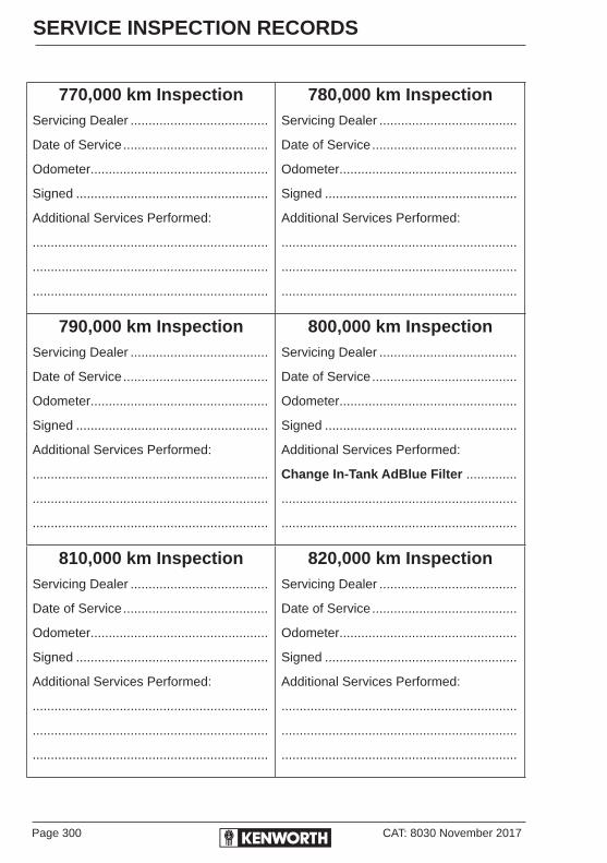
Page 300 CAT: 8030 November 2017
SERVICE INSPECTION RECORDS
770,000 km InspectionServicing Dealer ......................................
Date of Service ........................................
Odometer.................................................
Signed .....................................................
Additional Services Performed:
.................................................................
.................................................................
.................................................................
780,000 km InspectionServicing Dealer ......................................
Date of Service ........................................
Odometer.................................................
Signed .....................................................
Additional Services Performed:
.................................................................
.................................................................
.................................................................
790,000 km InspectionServicing Dealer ......................................
Date of Service ........................................
Odometer.................................................
Signed .....................................................
Additional Services Performed:
.................................................................
.................................................................
.................................................................
800,000 km InspectionServicing Dealer ......................................
Date of Service ........................................
Odometer.................................................
Signed .....................................................
Additional Services Performed:
Change In-Tank AdBlue Filter ..............
.................................................................
.................................................................
810,000 km InspectionServicing Dealer ......................................
Date of Service ........................................
Odometer.................................................
Signed .....................................................
Additional Services Performed:
.................................................................
.................................................................
.................................................................
820,000 km InspectionServicing Dealer ......................................
Date of Service ........................................
Odometer.................................................
Signed .....................................................
Additional Services Performed:
.................................................................
.................................................................
.................................................................

CAT: 8030 November 2017 Page 301
SERVICE INSPECTION RECORDS
830,000 km InspectionServicing Dealer ......................................
Date of Service ........................................
Odometer.................................................
Signed .....................................................
Additional Services Performed:
.................................................................
.................................................................
.................................................................
840,000 km InspectionServicing Dealer ......................................
Date of Service ........................................
Odometer.................................................
Signed .....................................................
Additional Services Performed:
.................................................................
.................................................................
.................................................................
850,000 km InspectionServicing Dealer ......................................
Date of Service ........................................
Odometer.................................................
Signed .....................................................
Additional Services Performed:
.................................................................
.................................................................
.................................................................
860,000 km InspectionServicing Dealer ......................................
Date of Service ........................................
Odometer.................................................
Signed .....................................................
Additional Services Performed:
.................................................................
.................................................................
.................................................................
870,000 km InspectionServicing Dealer ......................................
Date of Service ........................................
Odometer.................................................
Signed .....................................................
Additional Services Performed:
.................................................................
.................................................................
.................................................................
880,000 km InspectionServicing Dealer ......................................
Date of Service ........................................
Odometer.................................................
Signed .....................................................
Additional Services Performed:
.................................................................
.................................................................
.................................................................
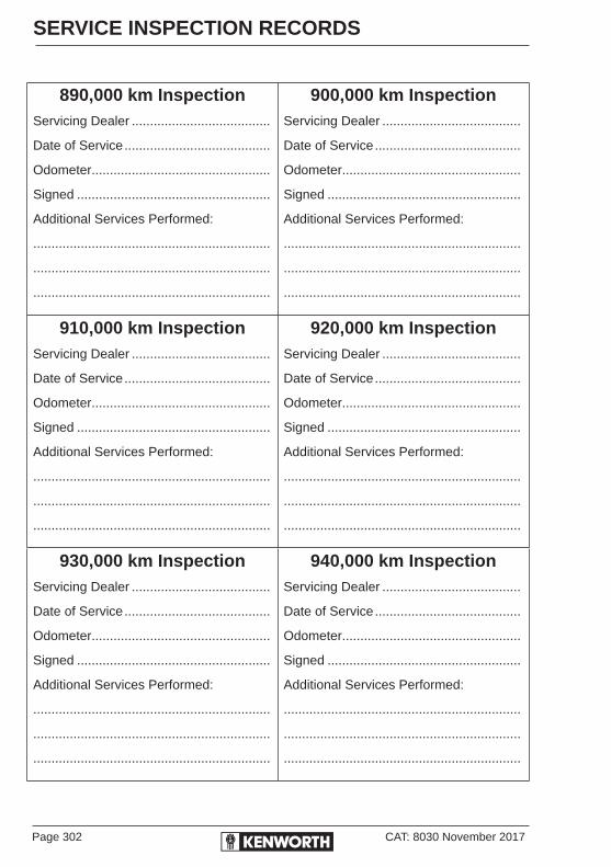
Page 302 CAT: 8030 November 2017
SERVICE INSPECTION RECORDS
890,000 km InspectionServicing Dealer ......................................
Date of Service ........................................
Odometer.................................................
Signed .....................................................
Additional Services Performed:
.................................................................
.................................................................
.................................................................
900,000 km InspectionServicing Dealer ......................................
Date of Service ........................................
Odometer.................................................
Signed .....................................................
Additional Services Performed:
.................................................................
.................................................................
.................................................................
910,000 km InspectionServicing Dealer ......................................
Date of Service ........................................
Odometer.................................................
Signed .....................................................
Additional Services Performed:
.................................................................
.................................................................
.................................................................
920,000 km InspectionServicing Dealer ......................................
Date of Service ........................................
Odometer.................................................
Signed .....................................................
Additional Services Performed:
.................................................................
.................................................................
.................................................................
930,000 km InspectionServicing Dealer ......................................
Date of Service ........................................
Odometer.................................................
Signed .....................................................
Additional Services Performed:
.................................................................
.................................................................
.................................................................
940,000 km InspectionServicing Dealer ......................................
Date of Service ........................................
Odometer.................................................
Signed .....................................................
Additional Services Performed:
.................................................................
.................................................................
.................................................................

CAT: 8030 November 2017 Page 303
SERVICE INSPECTION RECORDS
950,000 km InspectionServicing Dealer ......................................
Date of Service ........................................
Odometer.................................................
Signed .....................................................
Additional Services Performed:
.................................................................
.................................................................
.................................................................
960,000 km InspectionServicing Dealer ......................................
Date of Service ........................................
Odometer.................................................
Signed .....................................................
Additional Services Performed:
.................................................................
.................................................................
.................................................................
970,000 km InspectionServicing Dealer ......................................
Date of Service ........................................
Odometer.................................................
Signed .....................................................
Additional Services Performed:
.................................................................
.................................................................
.................................................................
980,000 km InspectionServicing Dealer ......................................
Date of Service ........................................
Odometer.................................................
Signed .....................................................
Additional Services Performed:
.................................................................
.................................................................
.................................................................
990,000 km InspectionServicing Dealer ......................................
Date of Service ........................................
Odometer.................................................
Signed .....................................................
Additional Services Performed:
.................................................................
.................................................................
.................................................................
1,000,000 km InspectionServicing Dealer ......................................
Date of Service ........................................
Odometer.................................................
Signed .....................................................
Additional Services Performed:
Change In-Tank AdBlue Filter ..............
.................................................................
.................................................................


CAT: 8030 November 2017 Page 305
INDEX
A
A-Service 10,000 klms 240Accelerating 124Accessory drive belts 150
belt tension 151installation 150re-tensioning new belts 151serpentine belts 151
AdBlue (DEF) 70 DEF AdBlue quantity 69 AdBlue filling 71 in tank filter service 247 air filter service 247Adjustable steering column 204Air compressor 163
operation 163Air conditioner 54, 190Air cleaners 149
filter replacement 149 intake system 149Air leaks 164Air loss emergency procedure 37Air pressure gauges 36, 164Air suspension 44, 131
air suspension pressure gauge 131height/air pressure 131deflated air spring(s) 131deflate switch/dump valve 44
Air supply system 99, 161air leaks 164air system pressure gauges 36air tanks 162air system silencers 216function test 162water ejection valves 162
ABS brakes 106, 159 ABS fault codes 159 warning lamp 106 off-road function switch 109Approaching your vehicle 22Automatic traction control 107Automatic transmissions 82, 196
automatic transmission retarder 82checking auto fluid levels 195
cold check 196hot check 196operating 82oil change 195oil sampling 146parking brake 82
Automatic slack adjusters 157free stroke measurement 157 adjusted chamber stroke 158
AutoVue Lane Departure Warning 111Axle stops 202Axle, cross wheel differential lock 115Axle, inter-axle differential lock 116Axle housing breather vents 212
B
B-Service 20,000 klms 242Batteries 176
battery isolation switch 176connecting jumper cables 182charging 177disconnecting jumper cables 182fast battery charging 177hydrometer readings 180maintenance free batteries 180overcharging 176undercharging 176slow battery charging 176, 179removal & installation 180
Belt tensions 151re-tensioning new belts 151
Bobtail - unloaded trailer 113Bogged in sand, mud or ice 137Brakes system 99, 155
application air gauge 100 before leaving cab 101brake & slack adjuster lubrication 156brake safety 104checks and adjustments 156disc brakes 105emergency braking 104front brakes 100full combination 101linings 156

Page 306 CAT: 8030 November 2017
INDEX
Cleaning the vehicle 184painted surfaces 184aluminium & chrome 185cabin trim 185engine 187interior 185oil & grease 186weather stripping 187
Clearance lights 43Climbing and decending 123Clutch 198
clutch adjustment 199clutch brake & travel 76double clutching 77linkage 198normal driving 77operation 78release bearing 200 clutch brake 200 cross shaft bushings 200 clutch control linkage 200 pilot bearing 200 release bearing wear pads 200riding the clutch 78starting 78tips 79
Coasting 122COE (K200) Engine acces 14Conventional hood hold downs 12Cooling system 152
coolant 152standard system refill 153topping up 153temperature gauge 36
Cruise control 47to turn on 47to turn off 47to set 47to resum e 48to disengage 48
Cross shaft bushings 200Cross wheel diff lock 115Cummins engine brake 49Cummins engine management 51 diagnostic fault codes 51
lubrication 156non-ABS 105normal run position 102operation 100overheated brakes 105parking brake 100rear brakes 100spring brakes manual release 135system-safety and emergency 104system truck park 104trailer brake 103initial charge 102trailer park 102using brake system 99
Breakdown/Roadside assistance xvii, 227
C
C-Service 40,000 klms 243Cab
access 5checks daily 23controls heater/AC 56heater/air cond 188, 190layout 29, 30mounted power supply socket 46special precautions 189storage 58tilt system 14 how to raise and lower the cab 16 to raise the cab 16 to lower the cab 16 general maintenance 18 remove excess air 18 system contamination 19cab and frame access 5
Castrol master service chart xvii, 253Central locking (RKE) 3Change of ownership 231, 233Chassis & Cab finish 184
checks daily 23Chassis lubrication points 248City driving, cruising 125

CAT: 8030 November 2017 Page 307
INDEX
D
Daily checks 23engine compartment 23chassis and cab 23
Dana rear axle 211Dashboard layouts (typical)
K200 29Conventional 30
Descending a grade 122Diagnostic/fault/flash codes 51 how to display 51Dimmer switch 43Disc Brakes 105Dome (interior) light 43Door lock and keys 1 lock and unlock doors 1Double clutching 77Downhill grades 123Driver diagnosis UltraShift 88Drive axle 115Drive axle temperature gauge 121Driver information pack (DIP) xviDriver controlled diff-lock 115Driver’s checklist 21Driver’s seat 59Driving tips & techniques 122Driving
general conditions 129habits 129tips & techniques 122unloaded trailer - bobtail 113with deflated air springs 131
Dual range axle 119operating 115starting up 119low to high 120high to low 121
Dump valve 44
E
Eaton Fuller transmissions 85
Economical driving 127Electronic brake safety system 106 ABS 106 warning lamp 106 fault codes 159 ATC 107 DTC 108 ESP 108 TRM 108 ACB 108ECU - Self test lights 51Emergency
braking 104checklist 21equipment 21flasher switch 42left hand headlight 42
Engineaccess conventional 12access K200 14aftertreatment systems 68 ISLe5, ISMe5 & X15e5 engines 68 diesel exhaust fluid 69, 70 DEF quality 69 AdBlue 70Diesel Particulate Filter (DPF) 71 DPF regeneration 72Selective Catalytic Reduction (SCR) 68 EAS tampering 69 EAS warning lights 71 regeneration process 72 regeneration switch 73before driving away 66before stopping engine 138belt tension 151brakes 115cleaning 187contol unit 51electronic engine 183engine manufacturer’s pack xvifan switch (override) 46management/fault codes 51operating the engine 63
normal starting 63before driving away 66engine warm up 64
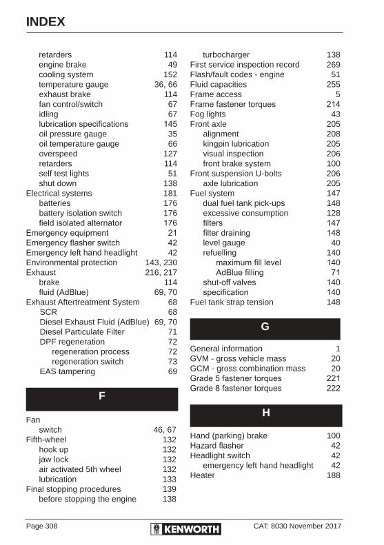
Page 308 CAT: 8030 November 2017
INDEX
turbocharger 138First service inspection record 269Flash/fault codes - engine 51Fluid capacities 255 Frame access 5Frame fastener torques 214Fog lights 43Front axle 205
alignment 208kingpin lubrication 205visual inspection 206front brake system 100
Front suspension U-bolts 206axle lubrication 205
Fuel system 147 dual fuel tank pick-ups 148
excessive consumption 128filters 147filter draining 148level gauge 40refuelling 140 maximum fill level 140 AdBlue filling 71shut-off valves 140specification 140
Fuel tank strap tension 148
G
General information 1GVM - gross vehicle mass 20GCM - gross combination mass 20Grade 5 fastener torques 221Grade 8 fastener torques 222
H
Hand (parking) brake 100Hazard flasher 42Headlight switch 42 emergency left hand headlight 42 Heater 188
retarders 114engine brake 49cooling system 152temperature gauge 36, 66exhaust brake 114fan control/switch 67idling 67lubrication specifications 145oil pressure gauge 35oil temperature gauge 66overspeed 127retarders 114self test lights 51shut down 138
Electrical systems 181batteries 176battery isolation switch 176field isolated alternator 176
Emergency equipment 21Emergency flasher switch 42Emergency left hand headlight 42Environmental protection 143, 230Exhaust 216, 217
brake 114fluid (AdBlue) 69, 70
Exhaust Aftertreatment System 68 SCR 68Diesel Exhaust Fluid (AdBlue) 69, 70Diesel Particulate Filter 71DPF regeneration 72 regeneration process 72 regeneration switch 73EAS tampering 69
F
Fanswitch 46, 67
Fifth-wheel 132hook up 132jaw lock 132air activated 5th wheel 132lubrication 133
Final stopping procedures 139 before stopping the engine 138
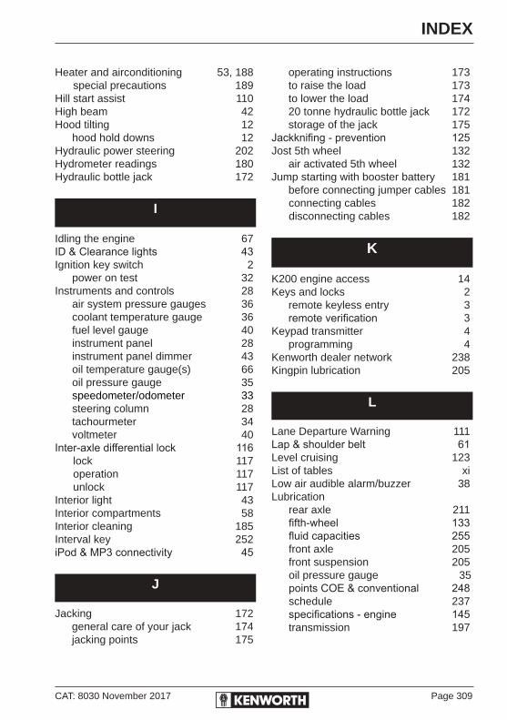
CAT: 8030 November 2017 Page 309
INDEX
Heater and airconditioning 53, 188special precautions 189
Hill start assist 110High beam 42Hood tilting 12
hood hold downs 12Hydraulic power steering 202Hydrometer readings 180Hydraulic bottle jack 172
I
Idling the engine 67ID & Clearance lights 43Ignition key switch 2
power on test 32Instruments and controls 28
air system pressure gauges 36coolant temperature gauge 36fuel level gauge 40instrument panel 28instrument panel dimmer 43oil temperature gauge(s) 66oil pressure gauge 35speedometer/odometer 33steering column 28tachourmeter 34voltmeter 40
Inter-axle differential lock 116lock 117operation 117unlock 117
Interior light 43Interior compartments 58Interior cleaning 185Interval key 252iPod & MP3 connectivity 45
J
Jacking 172 general care of your jack 174 jacking points 175
operating instructions 173 to raise the load 173 to lower the load 174 20 tonne hydraulic bottle jack 172 storage of the jack 175Jackknifing - prevention 125Jost 5th wheel 132 air activated 5th wheel 132Jump starting with booster battery 181 before connecting jumper cables 181
connecting cables 182disconnecting cables 182
K
K200 engine access 14Keys and locks 2 remote keyless entry 3 remote verification 3Keypad transmitter 4 programming 4Kenworth dealer network 238Kingpin lubrication 205
L
Lane Departure Warning 111Lap & shoulder belt 61Level cruising 123List of tables xiLow air audible alarm/buzzer 38 Lubrication
rear axle 211fifth-wheel 133fluid capacities 255front axle 205front suspension 205oil pressure gauge 35points COE & conventional 248schedule 237specifications - engine 145transmission 197

Page 310 CAT: 8030 November 2017
INDEX
sampling 146Operating the engine 63
temperatures 27pressures 27
Operating the transmission 74manual transmissions 74auto transmission 82
Optimum operating temps 124Overheated brakes 105Overinflated tyres 168Oversteer 201Owner's responsibility 238
P
PACCAR customer support directory xviPanel light knob 43Parking brake 39, 100
brake system, operation 100valve 39
Periodic maintenance 239Power divider 116Power supply socket (cab mounted) 46Power steering 202Power on test 32Power windows 44Pre start checks 25
daily checks 23weekly operations 26
Preventive maintenance 141Putting the vehicle in motion 75
M
Magnetic drain plugs 220Main differential lock 115Maintenance service records 265Manual transmission 195
oil change 195operating 74shift patterns 80
Master lubrication chart 239Material hazards 143Meritor rear axle 117, 211Mirrors 44Mountain driving 123Mufflers 217
N
New vehicle precautions 22Noise control system 215 air intake system 215
air system silencers 216engine 215cooling 215engine fan shroud 218exhaust system 216hood insulation blankets 219inner fender & side skirts 216inspection & maintenance 217mufflers 217noise insulation blankets 216transmission & driveline 219
Normal starting procedure 63
O
Odometer 33Off-road function ABS/ATC 109Oil
change transmission oil 195draining 145level check 146pressure gauge 35reservoirs 146
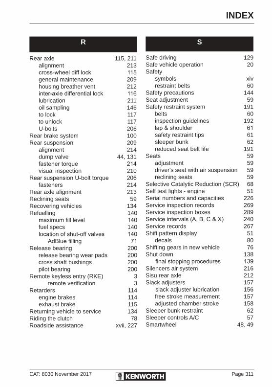
CAT: 8030 November 2017 Page 311
INDEX
R
Rear axle 115, 211alignment 213cross-wheel diff lock 115general maintenance 209housing breather vent 212inter-axle differential lock 116lubrication 211oil sampling 146to lock 117to unlock 117U-bolts 206
Rear brake system 100Rear suspension 209
alignment 214dump valve 44, 131fastener torque 214visual inspection 210
Rear suspension U-bolt torque 206fasteners 214
Rear axle alignment 213Reclining seats 59Recovering vehicles 134Refuelling 140
maximum fill level 140fuel specs 140location of shut-off valves 140 AdBlue filling 71
Release bearing 200release bearing wear pads 200cross shaft bushings 200pilot bearing 200
Remote keyless entry (RKE) 3 remote verification 3Retarders 114
engine brakes 114exhaust brake 115
Returning vehicle to service 134Riding the clutch 78Roadside assistance xvii, 227
S
Safe driving 129Safe vehicle operation 20Safety
symbols xiv restraint belts 60
Safety precautions 144Seat adjustment 59Safety restraint system 191
belts 60inspection guidelines 192lap & shoulder 61safety restraint tips 61sleeper bunk 62reduced seat belt life 191
Seats 59adjustment 59driver's seat with air suspension 59reclining seats 59
Selective Catalytic Reduction (SCR) 68Self test lights - engine 51Serial numbers and capacities 226Service inspection records 269Service inspection boxes 289Service intervals (A, B, C & X) 240Service records 267Shift pattern display 51
decals 80Shifting gears in new vehicle 76Shut down 138
final stopping procedures 139Silencers air system 216Sisu rear axle 212Slack adjusters 157
slack adjuster lubrication 156free stroke measurement 157adjusted chamber stroke 158
Sleeper bunk restraint 62Sleeper controls A/C 57Smartwheel 48, 49

Page 312 CAT: 8030 November 2017
INDEX
Trailer park valve 103Transmission 74, 195
automatic transmission 82, 196 check cold 196 check hot 196 operating auto transmission 82 auto transmission retarder 82UltraShift 85
driver diagnosis 88retrieving fault codes 88clearing fault codes 93fault codes 93
UltraShift Plus 95 gear display 95 reverse mode 97 start up and power down 96
COE (K200) only 74 low oil warning light 41 oil change 195 oil levels, checking 196 oil pressure 74 operating transmission 74 shift patterns 51, 80 temperature gauge 79warm-up 74warning light 41
Truck/trailer air supply valve 102Turbocharger 138, 165Turbo timer 50 locking in an idle period 50Torque specifications grade 5 221 grade 8 222Two-speed rear axle range switch 41Tyres inflation pressure 167
inspection 166matching tyres 170replacement 166, 170loading 169
Speedometer/Odometer 33Spring brakes - manual release 135Steering 201 axle stops 202
column 28, 204driveline 203u-joints 203driveshafts 203steering wheel care & maintenance 187 cleaning 187filter service and parts 202oversteer & understeer 201power steering filter 202
Stopping procedures 138, 139Storage compartment 58Suspension 205, 209
deflate switch 44fasteners, torque 209, 214general maintenance 209lubrication 205visual inspection 206
Suspension air pressure 131
T
Tachourmeter 34 use of tachourmeter 127Tanks dual fuel tanks 148 fuel tank strap tension 148Tilting the cab (K200, Cab-tilt) 14Towing 133
tow hitch 133vehicle recovery 134
Truck park valve (yellow knob) 39, 101Trailer
park brake release valve 103brake hand valve 113supply valve, (red knob) 39
Traction control (ATC) 107
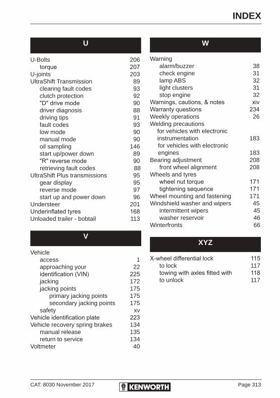
CAT: 8030 November 2017 Page 313
INDEX
U
U-Bolts 206torque 207
U-joints 203UltraShift Transmission 89 clearing fault codes 93 clutch protection 92 "D" drive mode 90 driver diagnosis 88 driving tips 91 fault codes 93 low mode 90 manual mode 90 oil sampling 146 start up/power down 89 "R" reverse mode 90
retrieving fault codes 88UltraShift Plus transmissions 95 gear display 95 reverse mode 97 start up and power down 96Understeer 201Underinflated tyres 168Unloaded trailer - bobtail 113
V
Vehicleaccess 1approaching your 22identification (VIN) 225jacking 172jacking points 175 primary jacking points 175 secondary jacking points 175safety xv
Vehicle identification plate 223Vehicle recovery spring brakes 134
manual release 135return to service 134
Voltmeter 40
W
Warningalarm/buzzer 38check engine 31lamp ABS 32light clusters 31stop engine 32
Warnings, cautions, & notes xivWarranty questions 234Weekly operations 26Welding precautions for vehicles with electronic instrumentation 183
for vehicles with electronicengines 183
Bearing adjustment 208front wheel alignment 208
Wheels and tyreswheel nut torque 171tightening sequence 171
Wheel mounting and fastening 171Windshield washer and wipers 45
intermittent wipers 45washer reservoir 46
Winterfronts 66
XYZ
X-wheel differential lock 115to lock 117towing with axles fitted with 118to unlock 117


PACCAR Australia and Kenworth Plant Bayswater Victoria
Every PACCARtruck is supported in the
field by a comprehensive networkof highly qualified dealers situated throughout
Australia, New Zealand and Papua New Guinea.Each with a history of excellence in the trucking industry.
Drive
r’s Ha
nd
bo
ok
20-64 Canterbury Road, Bayswater 3153P.O. Box 60, Bayswater, Victoria, Australia 3153Telephone: (03) 9721 1500Facsimile: (03) 9720 4144Internet: www.kenworth.com.au
Driver’s HandbookDriver’s Handbook
Drive
r’s Ha
nd
bo
ok


