91
8080/8085 RELOCATABLE MACRO ASSEMBLER MANUAL .Microtec . P.O. Box 60337 Sunnyvale, 94088 408-733-2919

8080/8085
RELOCATABLE MACRO ASSEMBLER MANUAL
.Microtec . P.O. Box 60337 Sunnyvale, CA~ 94088 408-733-2919

The following are differences between Microtec's Assembler and
the Intel Assembler described in Intel's 8080/8085 Assembly
Language Programming Manual #98-30lA.
- Microtec allows EBCDIC characters to be specified
- No limit to number of operands for DB or DW directives
- Only operators allowed are +,-,*,/,.LOW.,.HIGH.
- Expressions may c~ntain no blanks. In particular
the HIGH and LOW operators are delimited by periods.
- An instruction may not appear as an operand, e.g. (MOV A,B)
- Colons are not needed to terminate a label which starts
in column one.
- Comments may begin with asterisks or semicolons
- The comment field on a statement need not start with
a semicolon
- The following directives are not supported
REPT
IRP
IRPC
.- The following characters do not have any special meaning
as Macro Operators .. , , NUL %
- Macro Definitions may not be nested
TABLE OF CONTENTS
1.0 INTRODUCTION 1-1
2.0 ASSEMBLER LANGUAGE 2-1 Statements 2-2 Comment Statement 2-3 Reserved Symbols 2-3 Symbolic Addressing 2-4 Assembly Program Counter 2-6
3.0 SYNTAX 3-1 Character Set 3-1 Symbols 3-2 Constants 3-3 Expressions 3-5 Special Arithmetic Operators 3-5
4.0 DIRECTIVES 4-1 'ORG 4-3 END 4-4 EQU 4-5 SET 4-6 DB 4-7 DATA 4-7 DW 4-8 ACON 4-8 DDB 4-9 DS 4-10 EJEC 4-11 SPAC· 4-12 TITLE 4-13 LIST 4-14 NLIST 4-15 IF 4-16 ELSE 4-17 ENDIF 4-18
5.0 MACROS 5-1 Macro Heading 5-1 Macro Body 5-2 Macro Terminator 5-2 Macro Call 5-3 LOCAL 5-6 EXITM 5-8

6.0 RELOCATION Relocatable Symbols Relocatable Expressions Relocation Directives ASEG CSEG DSEG ORG PUBLIC EXTRN NAME STKLN
7.0 HOW TO USE THE ASSEMBLER The Assembler Assembler Operation Assembler Listing The Object Module Cross Reference Format
APPENDIX A - Assembler Error Codes
APPENDIX B - ASCII and EBCDIC Codes
APPENDIX C 8080/8085 Operation Codes
APPENDIX D - Hexadecimal Notation
APPENDIX ~ - Hexadecimal-Decimal Conversion Tables
6-1 6-2 6-3 6-4 6-5 6-6 6-7 6-8 6-9 6-10 6-11 6-12
7-1 7-1 7-1 7-2 7-7 7-9
8-1
8-4
8-5
8-8
8-9

INTRODUCTION
Microtec has developed a Relocatable Macro Assembler for
the 8080/8085 microprocessor.that translates Symbolic Machine
Code into relocatable object code which may then be processed
by Microtec's Linking Loader. The Assembler program is written
in FORTRAN IV to achieve compatibility with most computer·
systems. It is modular and may be executed in an overlay mode
should memory restrictions make that necessary. The program is
approximately 3800 FORTRAN statements in length, 20% of which
are comments. The program is written in ANSI standard FORTRAN
IV and no facility peculiar to anyone machine was utilized.
This was done in order to eliminate FORTRAN compatibility
problems.
The mnemonic Operation Codes as well as Directives are
identical to those utilized by Intel in their literature and
in their software products. This has been done to eliminate
any possible problems of program compatibility and to obviate
the necessity of learning new assembly languages.
The assembler is a two pass program that builds a symbol
table, issues helpful error messages, produces an easily read
program listing and symbol table, and outputs a computer
readable relocatable object (load) module.
The assembler features relocation, macro capability,
conditional assembly, symbolic and relative addressing, forward
references, complex expression evaluation, cro~s reference
listing and a versatile set of directives.

These features aid the programmer/engineer in producing
well documented, working programs in a minimum of time.
Additionally, the assembler is capable of generating data in
several number based systems as well as both ASCII and EBCDIC
character codes.
MicrQtec does not present any information in this manual
that will help the user understand the 8080 or 8085 micr6-
processor, nor has any information been included to help the
user write working programs. The reader is referred to the
Intel 8080/8085 Assembly Language Programming Manual #98-30lA.
1-2

ASSEMBLER LANGUAGE
The assembler language provides a means to create a
computer program. The features of the Assembler are designed
to meet the following goals:
• Programs should be easy to create
• Programs should be easy to modify
• Programs should be easy to read and understand
• A machine readable load module to be generated
This assembler language has been developed with the
following features:
• Symbolic machine operation codes (opcodes, mnemonics)
• Symbolic address assignments and reference
• Relative addressing
•. Data Creation statements
• Storage reservation statements
• Assembly listing control statements
• Addresses may be generated as constanbs
• Character codes may be specified as ASCII or EBCDIC
• Comments and remarks may be ericoded for documentation
• Cross reference table listing
• Relocatable object format
As assembly languag~ program is a program written in
symbolic machine language. It is comprised of statements.
A statement is either a symbolic instruction,. a directive
statement, a macro statement, or a comment.
2-0
The symbolic machine instruction is a written specification
for a particular machine operation expressed by symbolic
operation codes and sometimes symbolic addresses or operands.
Example:
ISAM MOV A,M
where:
ISAM - is a symbol which will represent the memory
address of this instruction.
MOV - is a symbolic opcode which represents the
bit pattern of the "move" instruction.
A - is a symbol, in this case a reserved symbol
representing the bit pattern for the accumulator.
M - is a symbol, another reserved symbol, representing
memory accessed through registers Hand L.
A directive statement is a statement which is not
translated into a machine instruction, but rather is
interpreted as a directive to the assembler program.
Example:
ABAT DW DELT
where:
ABAT - is a symbol. The assembler is to assign the
memory address of the first byte of t~e two
allocated bytes to this symbol.
DW - is a directive which directS· the. assembler program
to allocate two bytes of memory.
DELT - is a symbol representing an address. The assembler
is directed to place the equivalent memory address
into the two allocated bytes.
2-1

Statements
Statements are always written in a particular format. This
format is depicted below.
LABEL FIELD OPERATION FIELD OPERAND FIELD COMMENT FIELD
The statement is always assumed to be written on an 80
column data processing card or as an 80 column card image.
The Label Field is provided to assign symbolic names to
bytes of memory. If present, the label field may begin in any
column if it is terminated by a ~olon. It may also begin in
column one and not be terminated by a colon. A label may be
the only field on the statement.
The Operation Field is provided to specify a symbolic
operation code, a directive, or a macro call. If present this
field must either begiri past column one or be separated from
the Label Field by one or more blanks or a colon.
The Operand Field is provided to specify arguments for
the operation in the Operation Field. The Operand Field, if
present, is separated from the Operation Field by one or more
blanks.
The Comment Field is provided to enable the assembly
language programmer to optionally place an English message
stating the purpose or intent of a statement or group of
statements. The Comment Field must be separated from the
preceding field by one or more blanks or a semicolon.
2-2

Comment Statement
A Comment statement is a statement that is not processed
by the assembler program. It is merely reproduced on the
assembly listing. A comment statement is indicated by encoding
an asterisk or a semicolon as the first non-blank character~ I
Example:
·r THIS IS A COMMENT STATEMENT
Logical columns 73-80 are never processed by the assembler.
This field is'a good place for sequence numbers, if desired.
Reserved Symbols
This assembler has internally defined twelve symbols. They
are the register and segment names that Intel uses in their
product descriptions. These symbols have been defined to save
the user the trouble of defining them in each program.
Although these symbols need not be used, they typically are used
very frequently.
The user may assume the following statements have been
included at the beginning of each assembled program but they
will not appear on the program listing:
A EQU 7 H EQU 4
B EQU 0 L EQU 5
C EQU 1 M EQU 6
D EQU 2 SP EQU 6
E EQU 3 PSW EQU 6
In addition the following two symbols denote the
"stack" and "memory" segments of a program (see Section 6 ) •
STACK MEMORY
2-3

The values to which these labels have been assigned are the
Intel codes for the source or the destination of the micro
processor instructions.
These reserved labels may not be used in the label field.
to do so will generate an error flag.
Symbolic Addressing
When writing statements in symbolic machine language, i.e.
assembler language, the machine operation code is usually
expressed symbolically. For example, the machine instruction ,
that moves data from register B into the memory location
addressed by the contents of register pair H,L may be expressed
as:
MOV M,B
When translating this symbolic operation code and its
arguments into machine language for the 8080, the assembler
defines one byte containing 70H (112) at the memory location
in the current Assembly Program Counter. The address of the
translated byte is known because the Assembly Program Counter
is always set to hold the address of the byte currently being
assembled.
The user can optionally attach a label to such an
instruction. For example:
SAVE MOV M,B
The assembler, upon seeing a valid symbol in the label
field, assigns the equivalent address to the label. The
equivalent address is the address contained in the Assembly
Program Counter. In the given example, if the MOV instruction
is to be stored in the address 127, then the symbol SAVE
2-4

would be made equivalent to the value 127 for the duration
of the assembly.
The symbol could then be used anywhere in the source
program to refer to the location of the instruction. The
important concept is that the address of the instruction need
not be known; only the symbol need be used to refer to the
instruction location. Thus when jumping to the MOV instruction
the user could write:
JMP SAVE
When the "jump" instruction is translated by the assembler,
the address of the MOV instruction is placed in::the address
field of the JMP instruction.
It is also possible to use symbolic addresses which are
near other locations to refer to those locations without
defining new labels. This may be done through use of the +
and - operators. For example:
BEG
JMP BEG
JPE
MOV
HLT
BEG+4
A,B
MVI C, 'B'
INR B
In the abo v e, e x amp 1 e, the ins t r u c t ion " J MP BEG" ref e r s
to the "MOV A,B" instruction. The instruction "JPE BEG+4"
refers to the "INR B" instruction.
BEG+4 means the address of BEG plus four bytes. This
type of expression is called relative symbolic addressing and
given a symbolic address such as "BEG" it can be used as a
landmark to express several bytes before or after the symbolic
address.
2-5
Assembly Program Counter
During the assembly process the assembler maintains a
FORTRAN word that always contains the address of the next
memory location to be assembled. This word is called the
Assembly Program Counter. It is us~d by the assembler to
a,s s i g n add res s est 0 ass e m b 1 e d by t e s, but it i sal s 0 a va i l' a b 1 e
to the programmer.
The character "$" is the symbolic name of the Program
Counter. It may be used like any other symbol, but it may
not appear in the label field.
When using the "$", the programmer may think of it as
expressing the idea; "$" = "address of myself." For example:
10 JMP $
The jump instruction is in location 10. The instruction
directs the microprocessor to "jump to myself." The Program
Counter in this example contains the value 10 and the
instruction will be trans1at;ed to a "JMP 10." This could
be used for example when waiting for an interrupt.
2-6

SYNTAX
The Assembler Language is a language like any other. That
is, it has a character set, vocabulary, rules of grammer, and
allows for individuals to define new words or elements. The
rules that describe the language are termed the syntax of the
language.
For an expression or statement in assembler language to be
translated by the assembly program it must be written correctly
in accord with the rules of syntax.
Character Set
The following list of characters are the only ones that
the assembler will recognize. Use of any other characters
will cause the assembler to generate an error message.
Alphabetic Characters
ABC D E F G H I J K L M N 0 P Q R STU V W X Y Z
~ blank character
> greater than
< less then
single quote
comma
+ plus sign
minus sign
Numeric Characters
o 1 2 3 4 5 6 789
Special Characters
3-1
/ slash
$ dollar sign'
* asterisk
( left parenthesis
) right parenthesis
@ commercial at sign
period
& ampersand colon
exclamation semi-colon
" double quote' = equal sign
II sharp sign ? question mark
% percent
Symbols
A symbol is a sequence of characters. The first character
in a symbol must be alphabetic or the special characters ? or
@. Special characters except for the above two may not be
used in a symbol. Imbedded blanks are not permitted. The
user is cautioned not to use symbols that start with the ?
character as the assembler generates "local" symbols starting
with this character.
Only the first six characters of a symb~l are used by
the Assembler to define that symbol; the remaining characters
are for documentation. The parameter that dictates the number
of characters used to define a symbol may be changed in the
Fortran Source code.
The Assembler's symbol t~ble can contain up to 200 symbols.
If more symbols are requred, the symbol table may be increased
in size by changing a parameter in the Fortran Source code.
Symbols are used to represent arithmetic values, memory
addresses, bit arrays (masks),' etc. Examples' of valid symbols:
LABI
MASK
LOOP@NUM (symbol used is LOOP@N)
3-2

,Examples of invalid symbols:
Constants
ABORT*
lLAR
PAN N
(contains special character)
(begins with a numeric)
(embedded blank. symbol is PAN)
A constant is an invariant quantity. It may be an arith-
metic value or a character code. There are several ways of
specifying constants in this assembler language.
Decimal constants may be defined as a sequence of numeric
characters optionally preceded by a plus sign or a minus sign.
If unsigned, the value is assumed to be positive.
In most cases constants must be contained in one or two
bytes. A one byte constant can contain an unsigned number
with a value from 0 to 255. A two byte unsigned constant can
range from 0 to 65535. When a constant is negative is
equivalent two's complement representation is generated and
placed in the field specified. A one byte two's complement
negative number can range from -1 to -256. A two byte two's
complement number may range from -1 to -65536.
All constants are evaluated as 16 bit quantities, i.e.
modulo 65536. Whenever an attempt is made to place a constant
in a field for which it is too large, an error message is
generated by the assembler.
Other constants are defined utilizin~ a coded descriptor
after the constant. A leading 0 must be added to hexadecimal
constants that start with A~F. The following list indicates
th~ available descriptors.

B - binary
o octal
Q - octal
D - decimal
H - hexadecimal
Examples of these constants are:
l00llB 25 0FFH 37Q 255D 13570
As ASCII or EBCDIC character constant may be specified
by enclosing a single character within quote marks and preceding
it with an A for ASCII ro an E for EBCDIC. If no descriptor
is specified the string is assumed to be ASCII. Examples of
this constant form are:
MVI A, ' 1 '
MVI C,E'A'
ORI '0'
A character string may be specified by using the DB or
DATA directive. Character strings must follow the format
described for these directives (see Section 4). Character
strings may be specified as ASCII or EBCDIC in a similar
manner as the character constant.
string are:
A'TELETYPE CODES'
E'TERMINAL CODES'
123.8'
Examples of the character
Note that one byte of me~ory is required for each character
in a string. When a string is specified in a DB or DATA directive,
characters are stored in sequential bytes of memory beg~nning
at the first available byte.
3-4

To cause the code for a single quotation mark to be
generated in the character constant or string it must be
specified as two single quote marks. Example:
'DON' 'T '
The character ~ode for a single quotation mark will be
generated once for every two marks that appear contiguously
within the character string.
Expressions
An express ion is a .sequence 0 f one or more symbols,
constants, or other expressions separated by the arithmetic
operators·+,-~*,/ and the special arithmetic operatdrs
discussed later. Parenthesis are used in the normal manner
to establish the correct order of the arithmetic operators.
Expressions are evaluated left to right with multiplication
and division being performed before addition and subtraction.
The expression must resolve to a single unique value.
Consequently character strings are not permitted in expressions.
All expressions are evaluated modulo 65536 and hence are all
16 bit quanti'ies. In most cases the value of the final
expression must be contained in either one or two bytes. If
an attempt is made to place an expression in an one byte field
and the expression is too large, an error message is generated.
Examples of expressions:
PAM+3
(PAM+45H)/CAL
LOOP+ADDR/2
'A'+l
Special Arithmetic Operators
The special characters, ">", greater than and, "<", less
3-5

than, have been assigned as special arithmetic operators. They
correspond to the Intel operators .LOW. and .HIGH. and are
used to perform the following operations:
.LOW. or > - take low 8 bits of expression
.HIGH. or < - take high 8 bits of expression
These special operators are unary and may be used
anywhere in an expression. They have precedence over all
other operators, e.g. >A+B*C is not the same as >(A+B*C).
Example:
>IASM
<IASM
.LOW.E1+S
These operators have been provided to help the user
define two byte addresses as individual bytes whenever that
is desirable. The result of application of either of these
operators is a one byte value.
The following example demonstrates the utility of these
operators.
LXI H,BUFF
LOOP MOV A,M
CPI 13
JZ MAIN
INX H
MOV L,A
CPI . LOW. (BUFF+40) ;CHECK FOR END
JZ MAIN
JMP LOOP
3-6

DIRECTIVES
. The directives or pseudo-operat'ions are written as ordinary
statements in the assembler language, but rather than being
translated into equivalent machine language they are interpreted
as directives to the Assembler itself.
Through use of these directives, the Assembler will reserve
memory space, define bytes of data, control the listings, assign
values to symbols, etc.
This section describes all directives except those
primarily associated with macro assembly and relocation although
some directives such as ORG apply to both absolute assembly
and relocatable assembly.
The directives described in this section are:
ORG
END
EQU
SET
DB·
DATA
DW
ACON
DDB
DS
EJEC
SPAC
TITLE
LIST
NLIST
IF
Set Program Origin
End of Assembly
Equate a Symbol to an Expression
Equate a Symbol to an Expression
Data Definition
Data Definition (same as DB)
Define Word '
Address Constant (same as DW)
Define Double Byte
Define Storage
Advance Listing Form to next Page
Space lines on listing
Set Program Heading
List the Elements Specified
Suppress listing of the Elements Specified
Conditional Assembly Statement
4-1

ELSE
ENDIF
Conditional Assembly Statement Converse
End Conditional Assembly code
In the following descriptions, the brackets, { }, are
used to indicate optionality, or if more than one item appears
within the same pair of brackets, they indicate a choice.
4-2

ORG Set Program Origin (non relocatable mode)
The ORG directive is used to inform the assembler of :the
memory address to which the next assembled byte should be
assigned. All subsequent bytes will be assigned sequential
addresses beginning with this address.
If the program does not have an ORG as the first statement,
an ORG 0 is assumed and assembly will begin at location zero
with absolute assembly.
Example:
ORG 100H
( {label} ORG expression
where~
label - is an optional label which if present will
be equated to the given expression.
expression - a value which will replace the contents of
the Assembly Program Counter and bytes
subsequently assembled will be assigned
memory addresses beginning with this value.
Any symbols used in the expression must
be previously defined.
4-3
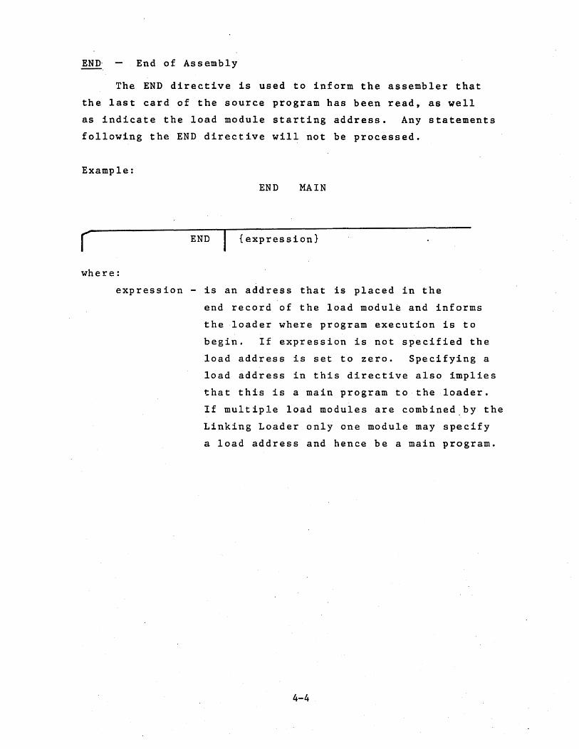
END-_ End of Assembly
The END directive is used to inform the assembler that
the last card of the source program has been read, as well
as indicate the load module starting address. Any statements
following the END directive will not be processed.
Example:
END MAIN
r END {expression}
where:
expression - is an address that is placed in the
end record of the load modul~ and informs
the -loader where program execution is to
begin. If expression is not specified the
load address is set to zero. Specifying a
load address in this directive also implies
that this is a main program to the loader.
If multiple load modules are combined~by the
Linking Loader only one module may specify
a load address and hence be a main program.
4-4

!QQ Equate a Symbol to an Expression
The EQU directive is used to ~ause the assembler to assign
a particular value to a new label. This value may be an
absolute value or be a relocatable segment value (see Section 6).
Example:
SEVEN EQU 7
r label EQU expression
where:
label - is a symbol defined by this statement
expression - is an expression whose value will be
assigned to the given label for the
duration of the current ~ssembly. An
attempt to reequate the same label will
result in an error. Any symbols used in
the expression must bepr~viously defined.
An external symbol may not be used in the
expression.
4-5

SET Equate a Symbol to an Expression
The SET directive may be used to set a symb6l equal to
a particular value. Unlike the EQU directive, ~ulitple SET
directives for the same symbol may be placed in the same source
program. The most recent SET directive determines the value of
the symbol at any given place in the source program.
Example:
( label SET
GO
GO
SET
SET
expression
5
GO+lO
where:
label - is a symbol defined by this statement
expression - is a value that will be assigned to the
given label until changed by another SET
directive. Any symbols used in the
expression must be previously defined.
An external symbol may not be used in the
expression.
4-6

DB DATA
Data Definition-
The DB and DATA directives are used to define up to 70
bytes of data. The assembler will allocate one byte if an
expression is given and will allocate several bytes if a
character string is given. All expressions must evaluate to
an one byte value or an error is generated. Negative values
are stored using their two's complement representation. If
an operand is a relocatable expression, it must be preceded
by the .LOW. or .HIGH. operators. If neither operator is
present an error is generated and the .LOW. operator is assumed.
Example:
{label}
where:
label
DB DATA
ITEM
OUT2
DB
DATA
DB
+122,17,.LOW.EXPl
6,.1 FH, 'A' + 1, 32 Q
A'ERR 1',7
- is an optional label which will be assigned
the address of the first byte defin~d.
operandi - is an evaluatable expression contained in one
byte, a character constant or an ASCII or
EBCDIC character string of up to 70 characters.
4-7
. ~
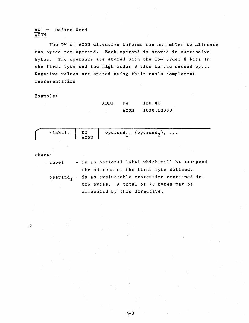
DW AeON
Define Word
The DW or AeON directive informs the assembler to allocate
two bytes per operand. Each operand is stored in successive
bytes. The operands are stored with the low order 8 bits in
the first byte and the high order 8 bits in the second byte.
Negative values are stored using their two's complement
representation.
Example:
{label}
where:
DW AeON
ADDl DW
AeON
lBH,40
1000,10000
operandl
, {operand2
},
label - is an optional label which will be assigned
the address of the first byte defined.
operandi - is an evaluatable expression contained in
two bytes. A total of 70 bytes may be
allocated by this directive .
4-8

DDB Define Double Byte
This directive is similar to the DW directive except for
the order in which the 16 bit value of each operand is stored.
The low order 8 bits of the operand are stored in the second
byte of the double byte and the high order 8 bits are stored
in the first byte. Negative values are stored using their
two's complement representation.
Example:
REVl DDB 1000,10000
( {label} DDB
where:
- is an optional label which will be assigned
the address of the first byte defined.
operand. - is an evaluatable expression contained in 1
label
two bytes. A total of 70 bytes may be
allocated by this directive.
4-9

DS Define Storage
The DS directive is used to reserve a block of sequenti~l
bytes of storage. This directive merely cause the program
counter t6 be advanced. Therefore, the contents of the reserved
bytes are unpredicatable.
Example:
PAT DS 62H
( {label} DS expression
where:
label - is an optional label which will be assigned
the address of the' first byte allocated.
expression - a value which specifies the number of bytes
to be allocated by this directive. Any symbols
used in this expression must be previously
defined. Expression may not contain any
re1ocatab1e symbols.
4-10

EJEC Advance Listing Form to next Page
This directive instructs the assembler to skip to the
top of' the next page on the listing form. Its purpose is to
make program listings' easier to read.
to start each subroutine on a new page.
will not appear on the listing.
( EJEC
4-11
Some programmers prefer
The EJEC directive

SPAC Space lines on listing
The SPAC directive causes one or more blank lines to appear
on the output listing. It enables the programmer to format
the program listings for easier reading. The directive itself
does not appear on the listing.
Example:
SPAC 7
( SPAC expression
where:
expression - evaluates to a value that determines how
many lines are to be skipped. Expression
may not be relocatable.
4-12

TITLE Set Program Heading
. The TITLE directive is used to print a heading at the
beginning of each page of the listing. The default heading
defined by the assembler and used if the programmer does not
specify one via this directive is: "8080/8085 ASSEMBLER VER
. MR". For a user specified title to appear on the first
page of the output listing, the TITLE directive must be the
first statement in the program. "
Example:
TITLE 'TEST PROGRAM'
( TITLE 'heading'
where:
heading - title which will be placed at the beginning
of each page. The heading may be up to 50
characters, with any additional characters
not appearing in the title. The heading is
delimited' by single quotes but if the
terminating quote is not present the first 50
characters will be used as the title. Heading
may contain no characters in which case the title
will be set to blanks.
4-13
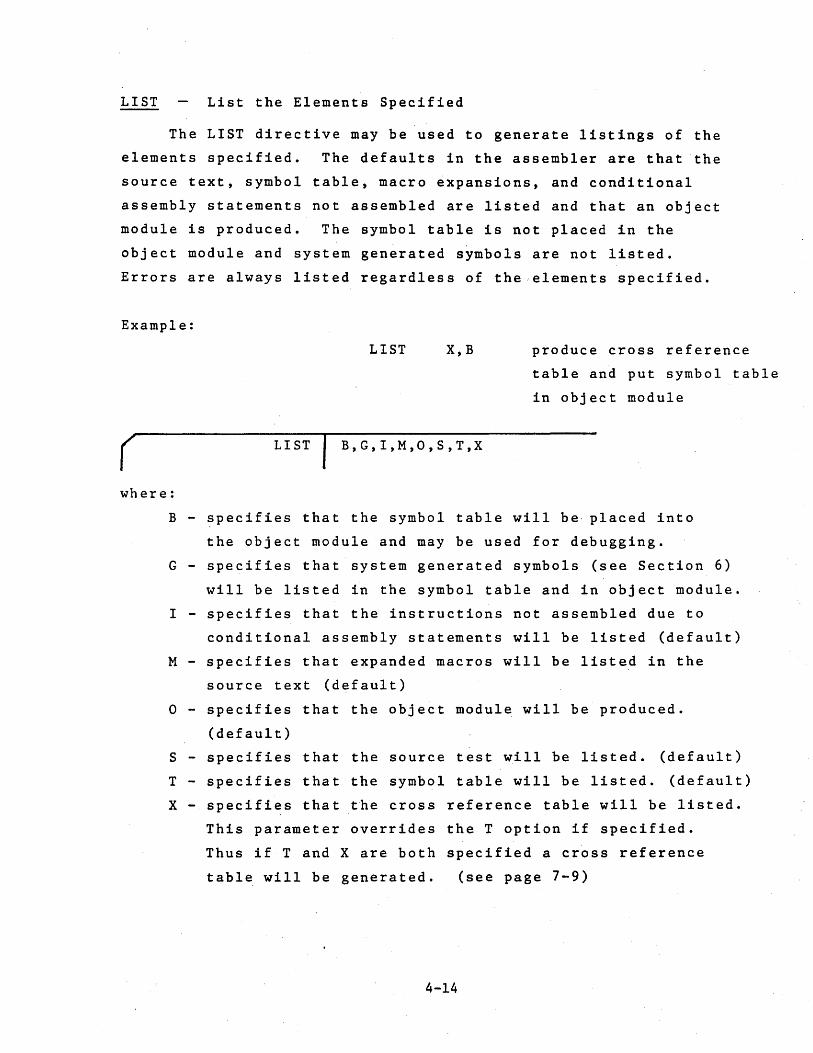
LIST List the Elements Specified
The LIST directive may be used to generate listings of the
elements specified. The defaults in the assembler are that the
source text, symbol table, macro expansions, and conditional
assembly statements not assembled are listed and that an object
module is produced. The symbol table is not placed in the
object module and system generated symbols are not listed.
Errors are always listed regardless of the elements specified.
Example:
( LIST
LIST X,B
B,G,I,M,O,S,T,X
produce cross reference
table and put symbol table
in object module
where:
B - specifies that the symbol table will be· placed into
the object module and may be used for debugging.
G - specifies that system generated symbols (see Section 6)
will be listed in the symbol table and in object module.
I - specifies that the instructions not assembled due to
conditional assembly statements will be listed (default)
M - specifies that expanded macros will be listed in the
source text (default)
° - specifies that the object module will be produced.
(default)
S - specifies that the source test will be listed. (default)
T - specifies that the symbol table will be listed. (default)
X - specifies that the cross reference table will be listed.
This parameter overrides the T option if specified.
Thus if T and X are both specified a cross reference
table will be generated. (see page 7-9)
4-14

NLIST Suppress Listing of the Elements Specified
The NLIST directive instructs the assembler to suppress
the listings of the elements specified. The listings may be
enabled again by the LIST directive. Errors generated by the
assembler are always listed regardless of the list flags. Thus
to obtain an output listing of only errors the user should
specify "NLIST SIt at the beginning of the program.
Example:
NLIST °
( NLIST B,G,I,M,O,S,T,X
do not produce an
object module
where:
B - specifies that the symbol table will not be placed
into the object module.,
G - specifies that system generated symbols will not be
listed in the symbol table or object module.
I - specifies that th~ instructions not assembled due to
conditional assembly statements not be listed.
M - specifies that expanded macros not be listed.
° - specifies that the object module will not be produced.
S - specifies that the source text will not listed. Only
those statements with errors will be listed.
T - specifies that the symbol table will not be listed.
X - specifies that a cross reference table will, not be
produced or listed.
4-15

IF Conditional Assembly Statement
The IF directive may be used to conditionally assemble
source text between the IF directive and the ELSE or ENDIF
directive. If the expression in the operand field is
evaluated to any non-zero value, the code will be assembled.
If the expression evaluates to a value of zero the code will
not be assembled. IF statements may be nested up to 16 levels
an.d app'ear in the source text at any place.
Example:
IF SYSTEM
( IF expression
where:
expression - evalutes to a value which determines whether
or not the assembly between the IF and following
ELSE or ENDIF will take place. Any symbols
used in this expression must be previously
defined. The expression may not be
relocatable.
4-16
ELSE Conditio~al Assembly Statement Converse
The ELSE directive is used in conjuction with the IF
directive and is the converse of the IF. If the expression
of the IF directive was zero t all statements between the ELSE
directive and the next ENDIF are assembled. If the expression
of the IF directive was non-zero, all statements between the
ELSE directive and the next ENDIF are not assembled.
The ELSE directive is optional and can only appear once
within in IF-ENDIF block.
Example:
IF MAIN
ELSE
ENDIF
( ELSE
4-17

ENDIF End Conditional Assembly Code
The ENDIF directive is used to inform the assembler where
the source code subject to the conditional assembly statement.
ends. In the case of nexted IF statements, an ENDIF is paired
with the most recent IF statement.
Example:
In the following code, if the expression SUM-4 is equal to
zero, the instructions between the IF and ELSE directives will
not be assembled and those between the ELSE and ENDIF will be
assembled. If SUM-4 is non-zero the opposite occurs. To not
list the non assembled instructions the "NLIST I" directive
may be used.
EI
IF SUM-4
assembled if SUM-4 ORI 0FAH
is non-zero ADC B
ELSE
assembled if SUM-4 ORI 07FH
is zero ADD C
ENDIF
r ENDIF
4-18

MACROS
A macro is a.sequence of instructions that can be inserted
in the assembly source text by encoding a single instruction, the
macro call. The macro definition is written only once and can
be called any number of times. The macro definition may contain
parameters which can be changed for each call. The macro facility
simplifies the coding of programs, reduces the chance of programmer
error, and makes programs easier to understand as the source
code need only be changed in one location, the macro definition.
A macro definition consists of three parts; a heading,
a body, and a terminator. This definition must precede any
macro call. A macro may be redefined at any time with the
latest definition of a macro name applying to a macro call.
A standard assembler mnemonic (e.g. ·LXI) may also be redefined
by defining a macro with the name LXI. In this case all
subsequent uses of the LXI instruction in the program will
cause the macro to be expanded.
Macro Heading
The heading, which consists of the directive MACRO, gives
the macro a name and defines any formal parameters for the macro.
r label MACRO I {parameter list}
Label specifies the macro name and may be any user defined
symbol. This name may be the same as other program defined
symbols since it has meaning only in the operation field. For
example, TAB could be the name of a symbol as well as a macro.
5-1
If a macro name if identical to a machine instruction or
an, assembler directive, the mnemonic is redefined as the macro.
Once a mnemonic has been redefined as a macro, there is no way
of returning that name to be a standa~d mnemonic. A macro
name may also be redefined as a new macro with a new body.
The operand field of the MACRO line contains the name of
dummy formal parameters in the order in which they occur on the
macro call. Each parameter is a symbol and multiple parameters
must be separated by comments. The scope of a formal parameter
is limited to its specific macro definition.
Macro Body
The firs't line of code following the MACRO directive
which is not a LOCAL directive is the start of the macro body.
These statements are placed in a macro file for use when the
macro is called. At expansion time, an error will be generated
if another macro is defined within a macro. No statements are
assembled at definition time including the Assembler directives.
Within the macro body, in any field, the name of a formal
parameter listed on the MACRO line may appear. If a parameter
exists, it is marked and the actual parameter from the macro call
will be substituted when the macro is called. Parameters are
not recognized in a comment statement or the comment fie~d of
a statement.
Macro Terminator
The ENDM directive terminates the macro definition. During
a Macro definition an ENDM must be found before another MACRO
statement may be used. An END statement that is found during
a macro definition will terminate the macro definition as well
the the assembly. The format of the ENDM is as follows:
5-2

r {label} ENDM
where:
label - is an optional symbol which becomes the symbolic
address of the first byte of memory following
the inserted macro.
Macro Call
A macro may be called by encoding the macro name in the
operation field of the statement. The format of the macro
call is shown below.
( {label} name parameter list
where:
label - is an optional label which will be assigned a
value equal to the address of the first
instruction in the macro.
name - is the name of the macro called. This name
should be defined by the MACRO directive or
an error message will be generated.
parameter - is a list of parameters separated by commas.
list These parameters may be constants, expressions.
symbols, character strings or any other text
separated by commas.
5-3

, ,The parameters in the macro call are actual parameters and
their names may be different than the formal parameters used in
the macro definition. The actual parameters will be substituted
for the formal parameters in the order in which they are written.
Commas may be used to reserve a parameter position. In this case
the parameter will be null. Any parameters not specified will
also be null. The parameter list is terminated by a blank or
a semicolon.
All actual parameters are passed as character strings into
the macro definition statements. Thus symbols are passed by
name and not by value. In other words the parameters are not
evaluated until the macro expansion is produced. Thus SET
directives within a macro may alter the value of parameters
passed to the macro.
During the macro expansion, the assembler recognizes
certain characters to have special meaning. The ampersand
"&", is used to concatenate the text of the definition line
and any actual parameters. During macro expansion, an ampersand
immediately preceding or immediately following a formal parameter
is removed and the substitution of the actual parameter occurs
at that point. If the ampersand is not immediately adjacent
to the parameter, the ampersand is not removed and remains
part of'the definition line. Ampersands within character
strings are not recognized as concatenation operators.
The angle brackets, "< >", are used to delimit actual
parameters that may contain other delimiters. When the left
bracket is the first character of any paramete~, all characters
between it and the matching right bracket are considered part of
that parameter. The outer brackets are removed when the parameter
is substituted in a line. Angle brackets may be nested for use
5-4

within nested macro calls. The brackets are the only way to
pass a parameter that contains a blank, comma or other delimiter.
F'or example to use the instruction "LXI H,0" as an actual
parameter, would require placing <LXI H,0> in the actual
parameter list. A null parameter may consist of the angle
brackets with no intervening characters.
An example of a macro call and its expansion is shown below.
Note that expanded macro code is marked with plus signs.
Definition
Call:
Source Code
Generated
GET
Z
LOOP
LOOP
+
+
+
+ENTRY
MACRO
MOV
RLC
Y
JZ
ADI
ENDM
CMC
GET
X,Y,Z
A,X
MAIN
-5
200,<STA DATA>,ENTRY
JMP MAIN
CMC
GET 200,<STA DATA>,ENTRY
MVI A,200
RLC
STA DATA
JZ MAIN
ADI -5
JMP MAIN
5-5

LOC'AL Define Local Symbol
As all labels, including those within macros, are global
to the complete program, a macro which contains a label and
which is called more than once will cause a duplicate label
error to be generated. To avoid this problem the user may
declare labels within macros to be "local" to the macro. Each
time the macro is called the assembler assigns each local
symbol a system generated symbol of the form ??nnnn. Thus the
first local symbol will be ??0001, the second ??0002, etc.
The assembler does not start at ??0001 for each macro but
increases the count for each local symbol encountered. The
symbols defined in the LOCAL directive are treated like formal
macro parameters and hence may be used in the operand field of
instructions. The operand field may not contain any formal
parameters defined on the MACRO directive line. As many
LOCAL directives as necessary may be included within a macro
definition but they must occur .immediately after the MACRO
directive and before the first line of the macro body. LOCAL
directives that ~ppear outside a macro definition will generate
an error.
Exampie:
Definition
First call
with R = 5
WAIT
. LABI
MACRO
LOCAL
MVI
DCR
JNZ
E~~DM
+ MVI
+??0001 DCR
+ JNZ
5-6.
R
LABI
B,R
B
LAB1
B,5
B
??0001
(
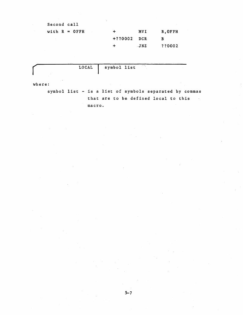
Second call
with R = OFFH
LOCAL
+ MVI
+??0002 DCR
+ ·JNZ
symbol list
B,OFFH
B
??0002
where:
symbol list - is a list of symbols separated by commas
that are to be defined local to this
macro.
5-7

EXITM Alternate Macro Exit
The EXITM directive provides an alternate method for
terminating a macro expansion. During a macro expansion, an
EXITM directive causes expansion of the current macro to stop
and all code between the EXITM and the ENDM for this macro
to be ignored. If macros are nested, EXITM causes code
generation to return to the previous level of macro expansion.
Note that an EXITM or an ENDM may be used to terminate a macro
expansion, but only an ENDM may be used to terminate a macro
definition.
In the following example the code following the EXITM
will not be assembled if DATA is zero.
STORE
( {label} EXITM
MACRO
IF
EXITM
ENDM
DATA
DATA
where:
label - is an optional label which will be given the
address of the instruction assembled after the
macro terminates.
5-8

RELOCATION
The object module produced by this assembler is in a
relocatable format. This allows users to write programs
whose final addresses will be adjusted by Microtec's Linking
Loader and which may also be changed without reassembling the
complete program. It also allows separate object modules
to be linked together into a final program.
Relocatable programming provides many advantage for the
user. Actual memory addresses are of no concern until the
final load time. Large programs may be easily separated into
smaller segments, developed separately, and linked together.
If one segment contains an error only it need be reassembled.
A library of routines may be used by many users once developed.
The Loader will adjust addresses to meet each user's requirements.
To take advantage of relocatability the user should under
stand the concept of program segments and how separate object
modules are linked together. A program segment is that part
of "a program which contains its own program counter and is
a logically distinct section of the program. At load time
the addresses for each segment may be specified separately.
This assembler provides for four program segments. The
CODE segment is typically the segment that contains the actual
machine instructions. In a ROM/RAM system it would be the
segment that would be placed into ROM. The data area of a
program is typically placed in the DATA segment. This segment
usually resides in RAM. This segment could contain actual
machine instructions. The STACK segment is used to contain
the program stack area and resides in RAM. Typically only the
main program makes references to the STACK segment and specifies
6-1
stack segment length. References are make to the stack segment
with the reserved symbol STACK. The MEMORY segement is that
portion of memory space not allocated to the other three segments.
References are made to this segment with the reserved symbol
MEMORY.
Although users may place actual code in the CODE or
DATA segments, only references may be made to the STACK and
MEMORY segments at assembly time.
As with non relocatable assemblers, users may also
specify absolute addresses when assembling a program. In this
case the object module will contain an absolute program designed
to run in a particular memory location.
The object modules of the assembler are combined or linked
together by a Linking Loader. The Loader converts all relocatable
addresses into absolute addresses and resolves references from
one module to ariother. Linkage b~tween modules is provided by
PUBLIC and EXTRN symbols. PUBLIC symbols are defined in one
object module and made available to all other object modules via
the Linking Loader. EXTRN symbols ire symbols referenced in
one module but defined in another module. The Linking Loader
links the PUBLIC's from one module with the EXTRN's from other
modules to resolve these references. A program may contain
both PUBLIC and EXTRN symbuls.
Relocatable Symbols
Each symbol in the assembler has associated with it a
symbol type which denotes the symbol as absolute or relocatable,
and the program segment to which the symbol belongs. Symbols
whose values do not change value depending upon program origin
are absolute symbols. Symbols whose value change when the
6-2

program origin is changed by the Linking Loader are termed
re10catab1e symbols. The reserved symbols STACK and MEMORY
discussed above are special forms of re1ocatab1e symbols.
External symbols are also re1ocatab1e. Absolute and relocatab1e
symbols may both appear in an absolute or relocatab1e segments.
Absolute symbols are defined as follows:
1. A symbol is in the label field when the program
is assembling an absolute segment of code.
2. A symbol is defined equal to an absolute expression
by the EQU or SET directives. This occurs even ifi
the program is assembling a re1ocatab1e segment.
Relocatable symbols are defined as follows:
1. A symbol is in the label field when the program
is assembling a CODE or DATA segment of code.
2. A symbol is defined equal to a relocatab1e expression
by the EQU or SET directives.
3. The reserved symbols STACK and ME~ORY are relocatab1e.
4. External (EXTRN) symbols are relocatab1e.
5. A reference to the program counter ($) while
assembling a re10catable segment is relocatable.
Relocatable symbols are also classified as CODE,DATA,
STACK, or MEMORY relocatab1e depending upon how they were
defined.
Relocatab1e Expressions
The relocatability of an expression is determined by
the relocation of the symbols that comprise the expression.
All numeric constants are considered absolute. Relocatable
expressions may be combined to produce ~n absolute expression,
a relocatable expression or in certain instances illegal
expressions. The following list shows those expressions
6-3

whose result is relocatable. ABS denotes an absolute symbol or
constant andREL denotes a relocatable symbol.
ABS+REL
REL+ABS
REL-ABS
.LOW.REL
.HIGH.REL
Relocatable symbols that appear in expression with any other
operators will cause an error, e.g. REL*REL. In addition
the difference of two relocatable symbols that were defined
in the same relocatable segment produces an absolute result.
Any com~ination. of two relocatable symbols from different
segments including externals (EXTRN) is an error condition.
Relocation Directives
The following pages describe those directives in the
assembler that pertain primarily to relocation. The no
menclature is the same as for the directives described in
Section 4. The directives describea are:
ASEG Specify Absolute Segment
·CSEG Specify Code Segment
DSEG Specify Data Segment
ORG Specify Origin
PUBLIC Specify PUBLIC symbols
EXTRN Specify External symbols
NAME Specify Module Name
STKLN Specify Stack Length
6-4

ASEG Specify Absolute Segment
The ASEG directive specifies to the assembler that the
following statements should be assembled in the absolute mode.
The ASEG remains in effect until a CSEG or DSEG directive is
assembled. The starting address for the ASEG program counter
is zero. At the start of assembly the program assumes an
ASEG directive has been specified and assembly proceeds in
the absolute mode.
r {label} ASEG
where:
label - is an optional label that will be assigned the
address of the next assembled instruction.
6-5
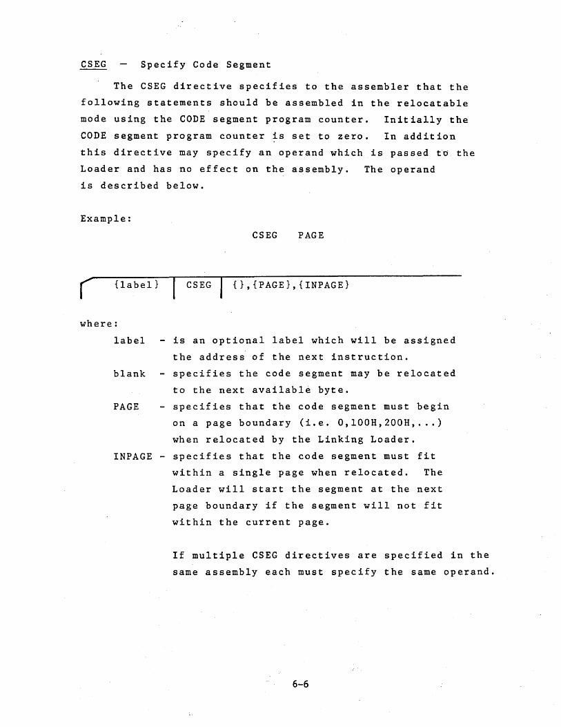
CSEG Specify Code Segment
The CSEG directive specifies to the assembler that the
following statements should be assembled in the relocatable
mode using the CODE segment program counter. Initially the
CODE segment program counter ~s set to zero. In addition
this directive may specify an operand which is passed to the
Loader and has no effect on the assembly. The operand
is described below.
Example:
CSEG PAGE
( {label} CSEG {},{PAGE},{INPAGE}
where:
label - is an optional label which will be assigned
the address of the next instruction.
blank - specifies the code segment may be relocated
to the next available byte.
PAGE - specifies that the code segment must begin
on a page boundary (i.e. O,lOOH,200H, ... )
when relocated by the Linking Loader.
INPAGE - specifies that the code segment must fit
within a single page when relocated. The
Loader will start the segment at the next
page boundary if the segment will not fit
within the current page.
If mUltiple CSEG directives are specified in the
same assembly each must specify the same operand.
6-6

DSEG Specify Data Segment
The DSEG directive specifies to the assembler that the
following statements should be assembled in the relocatable
mode using the DATA segment program counter. Initially the
DATA segment program counter is set to zero. In addition t
.this directive may specify an operand which is passed to the
Loader and has no effect on the assembly. The operand is
described below.
Example:
DSEG INPAGE
( {label} DSEG {}t{PAGE}t{INPAGE}
where:
label - is an optional label which will be assigned
the address of the next instruction.
blank - specifies the data segment may be relocated
to the next availabel byte.
PAGE - specifies that the data segment must begin
on a page boundary (i.e. O,lOOH t 200H t .•.• )
when relocated by the Linking Loader.
INPAGE - specifies that the data segment must fit
within a single page when relocated. The
Loader will start the segment at the next
page boundary if the segment will not fit
within the current page.
If mUltiple DSEG·directives are specified in the
same assembly each must specify the same operand.
6-7

ORG Set Program Origin (relocatable mode)
The ORG directive is used to inform the assembler of
the memory address to which the next assembled byte should be
assigned. This directive changes the program counter of
the segment which is currently being assembled, absolute, code
or data. When the ORG is in a relocatable program segment
the origin address must be an absolute expression or a
relocatable expression which is relocatablewithin the
current segment.
Example:
( {label}
where:
label
ORG $+30H
ORG expression
- is an optional label which will be equated
to the given expression.
expression - a value which will replace the contents of
the current segment program counter. Any
symbols used in the expression must be
previously defined.
6-8
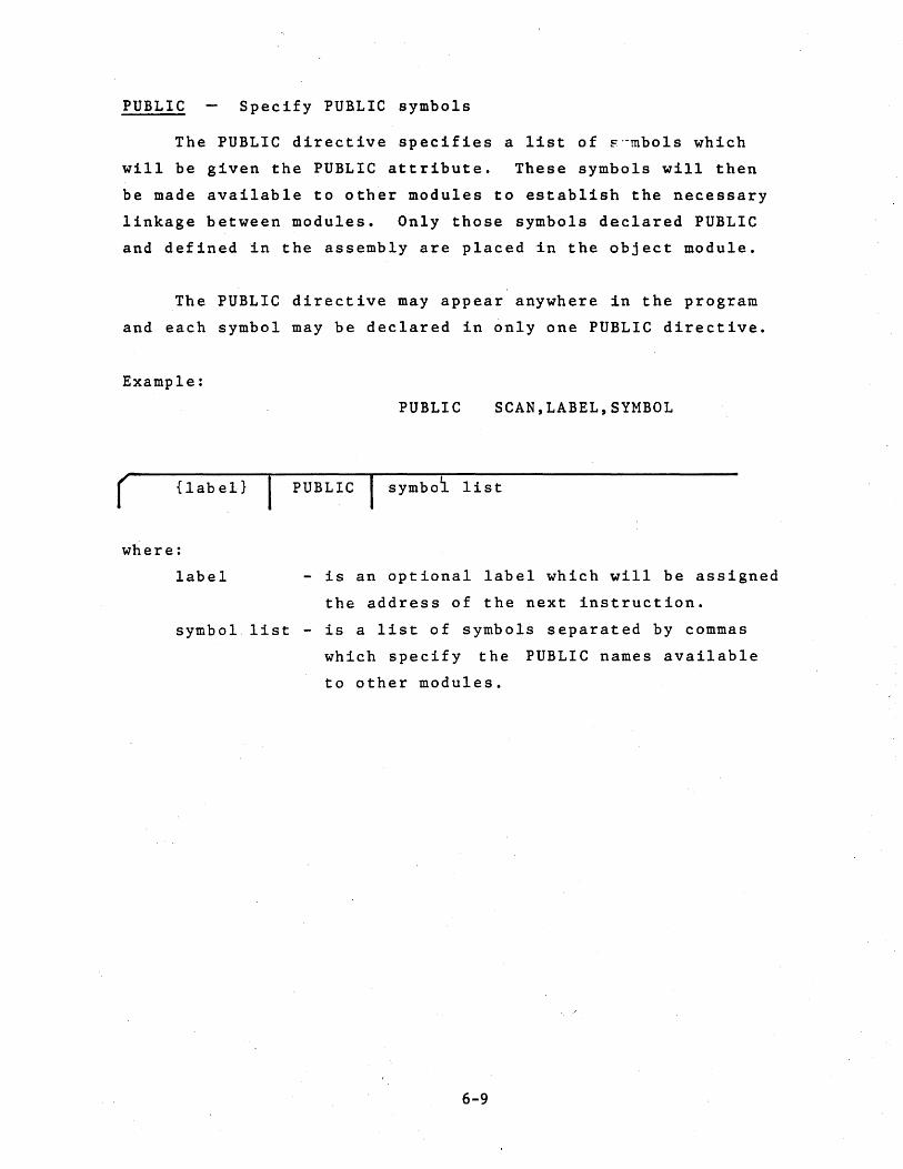
PUBLIC Specify PUBLIC symbols
The PUBLIC directive specifies a list of ~··mbols which
will be given the PUBLIC attribute. These symbols will then
be made available to other modules to establish the necessary
linkage between modules. Only those symbols declared PUBLIC
and defined ~n the assembly are placed in the object module.
The PUBLIC directive may appear anywhere in the program
and each symbol may be declared in only one PUBLIC directive.
Example:
PUBLIC SCAN,LABEL,SYMBOL
( {label} PUBLIC symbol list
where:
label - is an optional label which will be assigned
the address of the next instruction.
symbol. list - is a list of symbols separated by commas
which specify the PUBLIC names available
to other modules.
6-9
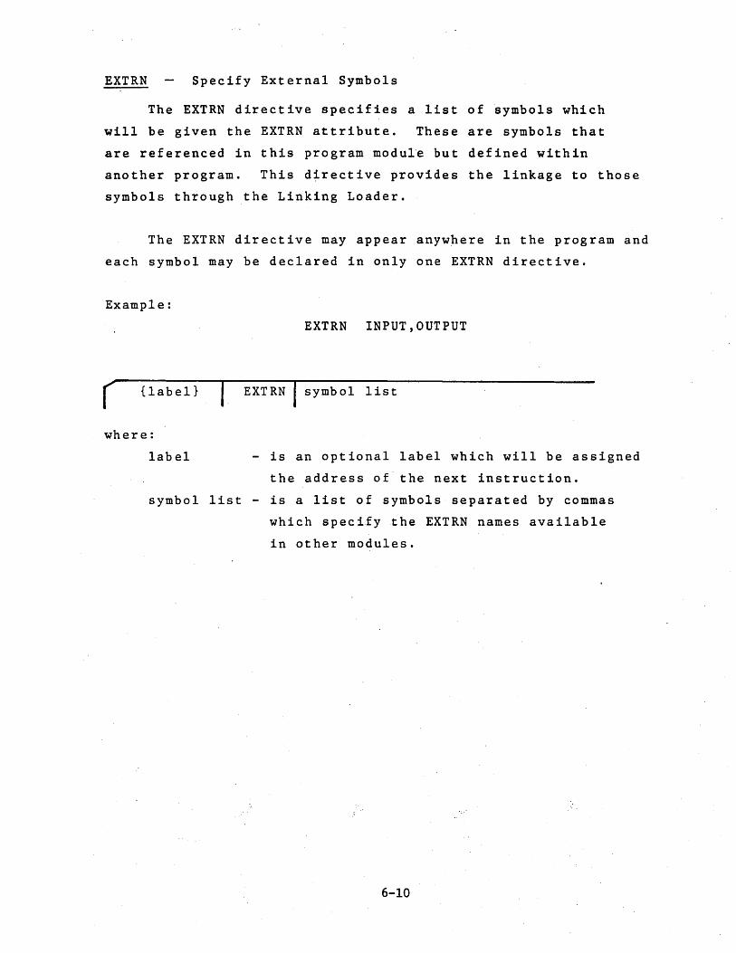
EXTRN Specify External Symbols
The EXTRN directive specifies a list of symbols which
will be given the EXTRN attribute. These are symbols that
are referenced in this program modu1'e but defined within
another program. This d~rective provides the linkage to those
symbols through the Linking Loader.
The EXTRN directive may appear anywhere in the program and
each symbol may be declared in only one EXTRN directive.
Example:
r {label}
where:
label
EXTRN INPUT,OUTPUT
I EXTRN symbol list
- is an optional label which will be assigned
the address of the next instruction.
symbol list - is a list of symbols separated by commas
which specify the EXTRN names available
in other modules.
6-10

NAME Specify Module Name
The NAME directive is used to assign a name 'to the object
module produced by the assembly. Only one NAME directive may
appear in a program. The module name is a handle used by the
Linking Loader when combining programs.
If no NAME directive is specified by the user the default
name "MODULE" is used.
Example:
NAME MULT
( {label} NAME name
where:
label - is an optional label which will be assigned
the address of the next instruction
name - is the name to be placed in the object module to
denote the module name to the Loader. This
name must follow all the rules of a symbol.
6-11

STKLN Specify Stack Length
The STKLN directive allows the user to specify the length
of the STACK segment generated by the Linking Loader. Typically
this directive is only used in the main program but other
programs may also specify a stack length. The Loader combines
all STACK segments into one segment.
If the user does not specify a STKLN directive the
assembler uses a default length of zero. More than one
STKLN directive may be placed in a program, only the last
one is used.
Example:
( {label}
where:
label
STKLN 20H
STKLN expression
- is an optional label which will be assigned
the address of the next instruction.
expression - an expression which indicates the length of
the stack segment. This expression may
not contain an relocatab1e symbols.
6-12

HOW TO USE THE ASSEMBLER
The Assembler
The Assembler program is usually supplied as an unlabeled
unblocked magnetic tape with 80 character card image records.
Other media may be requested.
The Assembler is written entirely in Fortran and is com
prised of a main program and several subroutines. The main
program appears first on the tape and the last subroutine is
followed by a tape mark. The Ass~mb1er may be compiled from
the tape.
The Assembler Installation Notes describe program
installation and any modification that may have to take place
for a particular computer. It is helpful to read these notes
before installing the program.
Assembler Operation
The Assembler is a two pass Assembler wherein the source
code is scanned twice. During the first pass the labels are
examined and placed into a symbol table. Certain errors may
be detected during Pass One; these will be displayed on the
output listing.
During Pass Two, the object code is completed, symbolic
addresses resolved, a listing and object module are produced.
Certain errors, not detected during Pass One may be detected
and displayed on the listing.
At the end of the Assembly process a symbol table or
cross reference table may be displayed.
7-1

The following steps are taken to assemble a source program:
1. Write a program utilizing instruction mnemonics and
directives. Encode the arguement fields with constants
labels, symbolic addresses, etc.
2. Transfer the source program to some computer· readable
medium; cards, tape, etc. This medium should correspond
to the input device expected by the Assembler. On
some systems, device assignments may be changed during
the course of an assembly by utilizing proper system
control'cards.
3. Inciude the source code as shown in the sequence in
Illustration I.
4. Execute the Assembler Program.
5. Get listing and object module as output.
Assembler Listing
During Pass Two of the assembly process a program listing
is produced. The listing displays all information pertaining
to the assembled program; both assembled data and the users
original source statements.
The listing may be used as a documentation tool through
the inclusion of the comments and remarks that describe the
function of t hep~ rt ic ula r program s.egmen t •
The main purpose of the listing is to convey all pertinent
information about the assembled program, i;.e. the memory addresses
and their contents. The load module, also produced during Pass
Two, contains the address and content information but in a format
that can be read only with great effort.
7-2

CARD ORDER
Illustration I t"
Read the Input Stream
first ) JCL or Other System Control Cards
( Required to Execute the Assembler
~--j Program
Read
by
Assembler
END
Source Code to be Assembled
Assembler End Statement
The illustration on page 7-6 is a sample of a typical
program listing.' Referring to the listing illustration, the
following information is pertinent:
• The assembler may detect error conditions during the
assembly process. The column titled "ERR" will contain
the error code(s) should the assembler detect one or
more errors in the associated line or source code. An
explanation of the individual error codes is given in
Appendix A.
• The column titled "LINE" contains decimal numbers which
are associated with the listing line numbers. The
maximum number of ~ines is a source program is 9999.
• The column titled "ADDR" contains a value which repre
sents the first memory address of the data shown in
bytes one to four on a given line or the value of
an EQU or SET directive. The hexadecimal number
under BI represents one byte of data to be stored in
the memory address. If there is a number under B2 it
represents data to be stored in the given memory address
plus one. Columns B3 and B4, if they contain a number,
similarly represent data to be stored in the memory
address plus two or three.
• To the right of the data bytes are the relocation types
of any relocatable operands. The types are as follows:
C - code, D - data, S - stack, M -,memory·, E - external.
• The users original source statements are reproduced
without alteration to 'the right of the above information.
Macro expansions are preceded with a plus sign.
7-4

• At the end of the" listing the assembler prints the
message "ASSEMBLER ERRORS = " with a cumulative count
of errors. The assembler substitutes three bytes of
NOP's when it cannot translate a particular opcode
and so provides room for patching the program if
desired.
• A symbol table or cross reference table is generated
at the end of each assembly listing that lists all
symbols utilized in alphabetic order along with any
relocatable symbol types.
7-5

~RA ~lNE ADDR Bl 82 Sl U4
1
o v U
M L
S S R ,
o -A E
2 l 4 5 6 7 8 9
10 11 12 Il lit 15' 16 0000 00 00 00 11 OOOl C6 2C 18 OOOS itO 19 20 0006 00 00 00 21 0009 40 22 OOOA Cl 00 00 23 0000 OA 24 OOOE 06 16 25 0010 2f' -26 0011 06 00 21 0013 01 00 00 28 29 lO II 0001 32 0064 38 30 l8 lO 33 0068 2' 38 30 38 l4 006C 35 -l5 006'0 36 0012 00 00 31 0014 17 38 0015 30 39 ItO 1t1 0000 78 .. a 0001 76 43 0002 OE 42 ' 44 0004 04 1t5 0005 BE 46 0006 Cl 04 00 1t7 0009 17 48 OOOA C3 00 00 49 0000 31 00 00 50 0010 CO 40 00 51 0013 C9 52 0014 DB 15 53 0016 11 12 00 S4 0019 32 78 00
E
c S ~
U ()
80~0/80~5 ASSEMHL~R V~~ 1.0MM PA<!E
• INPUT IS ~REE ~OHHAT NAME - SAMPLE L.IST X ' PU~LIC STORI.5TOHZ ExiRN- Ei,E2
• EXAMPL.E-OF HA~RO CAPAalLITY MACI - MAfRO - i;y
- suI ~~ , MOV xiy
CMA L.xi ENUM ,
, EXAMPLE at VA~IO~~ ASS~MBL~R ERRO~S , STAM RA~ -
AOI MOV EQU RAL. HOY JMP LDAX sui CMA
laO C,f is L.ABEL ERROR COD STAR •• S tt ~~.
Mvi u. LXI ".5US*5
• ASSEMBLER- DIRECTIVES -- OSfG' -, - '-, -OM{;- 100
ONE EQU i Qe- i~080/808S'
SUM, US stOR11 OW ,, __ ~r~~2 - ~a
CSt.G • [lAMPLE-O~-THE
- 8EO. MOY'-- HLT
Mvi INH CMP jH~ HAL. jH~
L.xi CALL
S~B HET IN-LXI ~T~
5 STAR ~~.1t8
VARIOUS INS!RUCTIO~S -~.B
C. 'B' t5 M E~.~
~EG SP,STACK ' •• 8
~SQ D,SUH.S SYM.1011S
IS~T ~ROGRAM NAM~ 16ET A CROSS REffRENC~ rA~L; IDECLARE PUBLICS- -O~CLAM£ EXTERNALS
UNDEfiNED OPCODE ILL.EGAL VALUE -UNUEfiNEO SYMBOL MISSING LABEL
SYNTAX ERROR SYNTAX ERROR ILL£GAL REGISTER fOR LCAl fORMA f ERROR - - --MULTIPLE DEfiNED LABEL ARGUM~NT ERROR -- -R~LOC~TION EAAO~
ISET DATA SEGMENT 'SET ORIGIN -EQUATE 1 AND ONE O~~IN~ A STRING-
RESERVE STORAGE D£fINE A WORD O~~IN~ DATA
I~~T ~ODE SEGMENT
LO~O ~SCII CHAR~~TER B
LOCAT~ON COUNTER ~~~~~ENC~
O~'AL CONSTANT
81NARY CONSTANT

55 ODIC EB XCHu 56 0010 06 6D U Mvi th>SUM 'LOWEN 8 BITS 51 001" OE 00 U MVI C •• HluH.S~M 'UPPEN 8 BITS 58 • S9 • 60 0001 CONTRa. SEt 1 61 0021 80 M~IN ADU ti 62 0022 HACI ti.C C~LL MACRO MACI 63 0022 D6 16 • sui" t!~
64 0024 41 • HOv tt;C 65 0025 2F • CMA 66 0026 01 Itl 00 • l.XI 8. tAt 61 0029 ItE ItF 50 ~~!~ 'NOP',O 68 002C 00 69 NL.l~T M DONtT EXPAND NEXT CALL. 7S IF CONTR~-l CONDIIIONAL'ASSEM~L~ 16 MVI A.6 77 XCHG 78 EL.SE 19 0034 21 22 00 L.XI- H.22H 80 0031 C3 21 00 ~ JMP M~IN 81 ENUIF 82 iF- CONTRL 83 003A 3E FF 'MVI ~ •• 1 8~ 003C EB XCHG 85 EL5E 86 L.Xi· H,OFfffH 81 JM., M~IN 88 f.NUlf 89 0030 ~N~
A5~~M8LER ERROAS • 12

CROSS ~EfER~NC~
LABtL VALUE REf'ER~N~E
A 0007 0 i 0000 0 ItEG C 0000 -41 !8 t . 0001 0 CONTRL 0001 -60 !5 82 o - 0002 0 t 0003 0 £1 E 0000 5 ~6 £2 E 0001 5 it 0004 0 L 0005 0 M 0006 0 MAIN C 0021 -61 ~O MEMORY M 0000 0 ONE 0001 -31 PS" 0006 0 SP 0006 0 STACK S 0000 0 $TAH 0000 ',-16 Z2 -25 36 STUMI D 0072 It ·j6 $TOM~ D 007" 4 .37 SUB C 0013 Z7 -51 $UM D 0060 -35 ~3 S .. 5~ 51

The' Object Module
As part of the Pass Two processing, the assembler produces
an object module. The object module is a machine readable
computer output in the form of punched cards, paper tape, etc.
The output module contains specifications for loading the memory
of the target microprocessor and provide the necessary linkage
to link object modules together.
The object module is normally punched out on the device
specified. However, through use of the LIST and NLIST directives
all or part of the output may be deleted.
The object module is produced as a series of card images
on the output punch device. The object module is compatible
with Intel's relocatable format although it is produced, in
a readable as opposed to binary format.
The object module may be loaded into Microtec's Linking
Loader which will then convert it to an absolute program
in Intel's standard hexadecimal format. This may then be
loaded into a development system or used to program a PROM.
A program is available from Microtec which will convert
the output of this assembler into a format directly usable
by Intel's MDS LINK and LOCATE commands. This program is
,provided on a diskette and executes on the Intel MDS system.
A sample object module is shown on the following page.
This'is 'the object module of the sample program shown on the
preceding pages.,
7-7

16200002720006STOR1*00740006STUR2*OUFl 06J_00000000000UOOC62C_00000004~C30UOOOAD61~ZfU60001000065 061A00026400383038302f38303635A6 . -061000027200000017302f . -063~0001000078760E4204BEC3U4VOI7C30000J10000CU~OOUC9D~lS2D 220C~003080011~OB3 . . - .. Z40AU003030EOOBE ZOOC000300000700CA 061600011600117200327800EB85 240[00020317001A0098 .. 060COOOll000066050 240A0002011EOOHI 063EUOOI1FOOOE00800616412F0141004E4f5000D616S32f114100212200C321009C 2208000338009H . _. . ~40A0002022000AE 060f00013A003EFFE889 040A0000010000fl ~E02~OFO

Cross Reference Format
The cross reference option is normally turned off. To turn
is on use "LIST X", to turn it off again use "NLIST X" (see
LIST and NLIST directives). The assembler will produce either
a cross reference table or a symbol table. The cross reference
table will be produced if "LIST X" has been specified. References
may only be accumulated during particular portions of the program
by turning the cross reference option on and off. However, to get
the listing of ~ross references, the option must be turned on
before the END statement. Typically the "LIST X" directive will
be one of the first statement in the source and never turned off.
An example of the cross reference output is as follows:
LABEL VALUE REFERENCE
A 0007 a ABC F45A -4 15 35
MAIN C 0000 35
TABLE 05lC -6 34 -54
LABEL and VALUE are self explanatory. Any flags on the left
of the value are the relocation types of the symbol. Under
REFERENCE, a value preceded by a minus sign indicates that the
symbol was defined on that line. A value of 0 as the only
entry on the line indicates this is an internal system symbol
(e.g. A,B,C, ... ). Line numbers not preceded by a minus sign
indicate a reference to the symbol. Note that for SET symbols,
move than one definition may appear for a given symbol as in
TABLE above.
7-9

APPENDIX A
ASSEMBLER ERROR CODES
If errors in the source code are detected during the
assembly process, an indication of the type of error is printed
on the listing on the same line as the statement in error.
The following list should serve as a guide to diagnose the
error. The listing always displays a total error count.
A - Argument error. The argument is missing or contains
an illegal character.
C - Macro Substitution error. When substituting actual
macro parameters for formal macro paramters, the 80
column source line limit was exceeded.
D - Duplicate Label error. The label in the statement has
previously appeared in the label field. A label on
SET directive previously appeared in a statement
other than a SET or a label on a statement other than
a SET statement now appears on a SET statement. A
label appears more than once in an EXTRN or PUBLIC
directive or a symbol defined in an EXTRN directive
appears in the label field of some statement.
E - Relocation error. The inst~uction contains an operand
that violates a rule of relocation. An operand that
should be absolute is relocatable or an EQU or SET
directive make reference to an external symbol.
F - Format error. The inStruction hi~ been written in a
format which is not permitted. This error usually
indicates a trailing comma and the instruction is
assembled properly.
8-1

L - Label error. A label contains an invalid character of
starts with a numeric character.
M - Missing Label. This statement requires a label.
N - Macro Nesting error. When nesting macros the
available number of levels was exceeded.
o - Opcode error. The opcode mnemonic has not been
recognized as a valid mnemonic, directive, or a
macro call. Also a macro defined within another macro
or conditional statements nested too deeply. ELSE,
ENDIF, or ENDM used without preceding IF or MACRO.
LOCAL directive used outside of MACRO body or more
than one NAME directive in a program.
R - Register error. The register expression could not
be evaluated or when evaluated was greater than 7 or
less than O. The register field was not found or a
specified register is not valid for the given opcode.
S - Syntax error. A rule of syntax has been violated
in the statement. Parenthesis are not nested
properly or possibly two operators appear in sequence.
T - Table overflow. Symbol table is full - assembly
continues. An attempt was made to define too many
macros or too many parameters in nested macro calls.
U - Undefined symbol. There is a symbolic name in the
operand field which has never been in the label field.
The symbol should have been previously defined for
certain' directives and was not but may have been
defined after the directive.
8-2

v - Value error. An evaluated expression or constant is
out of range for the field of the actual machine
instruction in which it is to be contained. A one
byte value is relocatable but was not preceded by a
.LOW. or .HIGH. operator. In this case it is forced
.LOW.
CROSS REFERENCE OVERFLOW AT The cross reference file
has been filled. Assembly continues and references are
not accumulated past this line. This message appears
in the cross r~terence table listing. Enlarge cross
reference file space or turn references 6ff for sections
of the program.
8-3

APPENDIX B
ASCII AND EBCDIC CODES
The Assembler will recognize only the following characters.
The equivalent codes are expressed in hexadecimal notation.
CHARACTER ASCII EBCDIC CHARACTER ASCII EBCDIC
0 30 F0 V 56 E5 1 31 Fl W 57 E6 2 32 F2 X 58 E7 3 33 F3 y 59 E8 4 34. F4 Z 5A E9 5 35 F5 6 36 F6 blank 20 40 7 37 F7 21 5A 8 38 F8 II 22 7F 9 39 F9 1/ 23 7B
$ 24 5B A 41 Cl % 25 6C B 4'2 C2 & 26 ·50 C 43 .C3 27 7D D 44 C4 ( 28 4D E 45 C5 ) 29 5D F 46 C6 * 2A 5C G 47 C7 + 2B 4F H 48 C8 2C 6B I 49 C9 2D 60 J 4A Dl 2E 4B K 4B D2 / 2F 61 L 4C D3 M 4D D4 3A 7A N 4E D5 3B 5E a 4F D6 < 3C 4C P 50 D7 = 3D 7E Q 51 D8 > 3E 6E R 52 D9 ? 3F 6F S 53 E2 @ 40 7C T 54 E3 U 55 E4
"
8-4

APPENDIX C
8080/8085 OPERATION CODES
The following table illustrates the proper format for
writing 8080/8085 instruct~ons. The operation code mnemonics
listed are the only valid opcodes for the assembler.
These symbols are used in the table.
D,S - indicates a source or destination register which
is one of the following: A,B,C,D,E,H,L,M
RP - indicates a register pair which may be one of the
following: B,D,H,SP
PSW - indicates the Program Status Word
eXPa - indicates an 8 bit value
eXP 16 - indicates a 16 bit value
ddd - the bit pattern representing one of the registers 555 denoted by D or S above.
follows:
The bit patterns are as
B - 000
E - 011
M - 110
C - 001
H - 100
A-Ill
D - 010
L - 101
rp - the bit pattern representing one of the register
pairs denoted by RP above. The bit patterns are as
follows:
B ~ 00 D - 01 H - 10 SP - 11
* - new instruction of 8085
When two states are shown for an instruction, the first
number is if the condition is not satisfied an~ the second
number is 'if the condition is satisfied.
8-5

SYMSOLIC FIRST BYTE NUMBER NUMBER OPCODE MACHINE CODE OF BYTES OF STATES
So So SOS5
Data Transfer
MOV D,S 01ddd555 1 5 4 MOV D,M 01dddll0 1 7 7 MOV M,S 01110555 1 7 7 MVI D,exPS' 00dddll0 2 7 7 MVI M,exPS 001 101 1 0 2 1 0 10 LXI RP, exP 16 OOrpOOOl 3 1 0 1 0 LOA eXP16 00111010 3 1 3 1 3 STA eXP16 00110010 . 3 1 3 1 3 LHLD eXP16 00101010 3 1 6 1 6 SHLD eXP16 00100010 3 1 6 1 6 LDAX RP 00rpl0l0 1 7 7 STAX RP 00rp0010 1 7 7 XCHG 11101011 1 4 4
Arithmetic Groue
ADD S 10000555 1 4 4 ADC S 1 0001 5'55 1 4 4 SUS S 10010555 1 4 4 SBS S 10011555 1 4 4 ADI exPS 11000110 2 7 7 ACI exPS 11001110 2 7 7 SUI exPS 11010110 2 7 7 SSI exps 11011110 2 7 7 INR 0 00dddl00 1 5 4 OCR 0 OOd d d 1.01 1 5 4 INX RP 00rp0011 1 5 6 DCX RP 00rpl0ll 1 5 6 DAD RP 00rpl001 1 1 0 1 0 DAA 00100111 1 4 4
L09ical GrouE
ANA S 10100555 1 4 4 XRA S 10101555 1 4 4 ORA S 10110555 1 4 4 CMP S 10111555 1 4 4 ANI exPS 11100110 2 7 7 XRI exPS 11101110 2 7 7 ORI exPS 11110110 2 7 7 CPI exPS 11111110 2 7 7 RLC 00000111 1 4 4 RRC 00001111 1 4 4 RAL 00010111 1 4 4 RAR 00011111 1 4 4 CMA 0010·1111 1 4 4 CMC 00111111 1 4 4 STC 00110111 1 4 4
8-6

SYMBOLIC FIRST BYTE NUMBER NUMBER OPCODE MACHINE CODE OF BYTES OF STATES
8080 8085
Branch Grou~
JMP eXP16 11000011 3 10 1 0 JNZ eXP 16 110,00010 3 1 0 7/10 JZ eXP 16 11001010 3 10 7/10 JNC eXP 16 11010010 3 1 0 7/10 JC eXP 16 11011010 3 1 0 7/10 JPO eXP 16 11100010 3 10 7/10 J PE eXP 16 11101010 3 1 0 7/10 JP eXP 16 11110010 3 1 0 7/10 JM eXP 16 11111010 3 10 7/10 CALL eXP 16 11001101 3 1 7 1 8 CNZ eXP16 11000100 3 11/1 7 9/18 CZ eXP 16 11001100 3 ' 1 1 / 1 7 9/18 CNC eXP 16 11010100 3 1 1/1 7 9/18 CC eXP 16 11011100 3 1 1/1 7 9/18 CPO eXP 16 11100100 3 1 1/1 7 9/18 CPE eXP 16 11101100 3 1 1/1 7 9/18 CP eX P16 1 1 1 10100 3 1 1 /1 7 9/18 CM eX P16 11111100 3 1 1/1 7 9/18 RET 11001001 1 1 0 1 0 RNZ 11000000 1 5/1 1 6/12 RZ 11001000 1 5/1 1 6/12 RNC 11010000 1 5/11 6/12 RC 11011000 1 5/11 6/12 RPO 11100000 1 5/11 6/12 RPE 11101000 ' 1 5/11 6/12 RP 11110000 1 5/11 6/12 RM 11111000 1 5/11 6/12 RST A llaaal11 1 1 1 1 2 PCHL 11101001 1 5 6
Stack, I/O and Machine Control Grou~
PUSH RP l1rpOl01 1 1 1 1 2 PUSH PSW 1 1 1 10 1 0 1 1 1 1 1 2 POP RP llrpOOOl 1 1 0 1 0 POP PSW 11110001 1 1 0 1 0 XTHL 11100011 1 1 8 1 6 SPHl. 11111001 1 5 6 I N eXP8 11011011 2 1 0 1 0 OUT eXP8 11010011 2 1 0 1 0 EI 11111011 1 4 4 01 11110011 1 4 4 HLT 01110110 1 7 5 NOP 00000000 1 4 4 RIM 00100000 1 * 4 SIM 00110000 1 * 4
8-7

APPENDIX D
HEXADECIMAL NOTATION
Hexadecimal notation is a convenient way to express binary
information. Each hexadecimal digit may be though of as
representing the information in four binary bits.
The assembled code is expressed in hexadecimal notation on
the output listing. Hexadecimal is the name of the base 16
number system.
DECIMAL HEXADECIMAL BINARY
0 0 0000
1 1 0001
2 2 '0010
3 3 0011
4 4 0100
5 5 0101
6 6 0110
7 7 0111
8 8 1000
9 9 1001
10 A 1010
11 B 1011
12 C 1100
13 D 1101
14 E 1110
15 F 1111
8-8

Appendix E
HEXADECIMAL-DECIMAL CONVERSION IABLE
This tabl~ allows conversions to b made between hexa-
decimal and decimal numbers. The ta: has a decimal range
of a to 4095. To convert larger nU=:l:>ers add the following
values to the table values.
Hexadecimal Decimal
1000 4096
2000 8192
3000 12228
4000 16384
5000 20480
6000 24576
7000 28672-
8000 32768
9000 36864
AOOO 40960
BOOO 45056
COOO 49152
DOOO 53248
EO,OO 57344
FOOO 61440
0 2 3 4 5 6 7 8 9 A B C 0 E F'
000 0000 0001 0002 0003 0004 0005 0006 0007 0008 0009 0010 0011 0012 0013 0014 0015 010 0016 0017 0018 0019 0020 0021 0022 0023 0024 0025 0026 0027 0028 0029 0030 0031 020 0032 0033 0034 0035 0036 0037 0038 0039 0040 0041 0042 0043 0044 0045 0046 0047 030 0048, 0049 0050 0051 0052 0053 0054 0055 0056'· 0057 0058 0059 0060 0061 0062 0063
040 0064 0065 0066 0067 0068 0069 0070 0071 0072 0073 0074 0075 0076 0077 0078 0079 050 0080 0081 0082 0083 0084 0085 0086 0087 0088 0089 0090 0091 0092 0093 0094 0095 060 0096 0097 0098 0099 0100 0101 0102 0103 0104 0105 0106 0107 0108 0109 0110 0111 070 0112 0",13 0114 0115 0116 0117 0118 0119 0120 0121 0122 0123 0124 0125 0126 0127
1080 0128 0129 Ol30 0131 0132 0133 0134 0135 0136 0137 0138 0139 0140 0141 0142 0143 1 1090· 0144 0145 0146 0147 0148 0149 0150 0151 01520153 0154 0155 ' 0156 0157 0158 0159 ,OAO 0160 0161 0162 0163 0164 0165 0166 0167 0168· 0169 0170 0171 0172 0173 0174 0175
lOBO 0176 0177 0178 0179 0180 0181 0182 0183 0184 0185 0186 0187 0188 0189 0190 0191
loco 0192 0193 0194 0195 0196 0197 0198 0199 0200 . 0201 0202 0203 0204 0205 0206 0207 1000 0208 0209 0210 0211 0212 0213 0214 0215 0216 0217 0218. 0219 0220 0221 0222 0223 IDEO 0224 0225 0226 0227 0228 0229 0230 0231 0232 0233 0234 0235 0236 0237 0238 0239
OFO 0240 0241 0242 0243 0244 0245 0246 0247 0248 0249 0250 0251 0252 0253 0254 0255 - -
.8-9

HEXADECIMAL·DECIMAL INTEGER CONVERSION (Cant'd)
0 1 2 3 4 5 6 7 8 9 A B C 0 E F AOO 2560 2561 2562 2563 2564 2565 2566 2567 2568 2569 2570 2571 2572 2573 2574 25~ Al0 2576 2577 2578 2579 2580 2581 2582 2583 2584 2585 2586 2587 2588 2589 2590 25~ A20 2592 2593 2594 2595 2596 2597 2598 2599 2600 2601 2602 2603 2604 2605 2606 26( A30 2608 2609 2610 2611 2612 2613 . 2614 2615 2616 2617 2618 2619 2620 2621 2622 26:
A40 2624 2625 2626 2627 2628 2629 2630 2631 2632 2633 2634 2635 2636 2637 2638 26: A50 2640 2641 2642 2643 2644 2645 2646 2647 2648 2649 2650 2651 2652 2653 2654 26! A60 2656 2657 2658 2659 2660 2661 2662 2663 2664 2665 2666 2667 2668 2669 2670 26~ A70 2672 2673 2674 2675 2676 2677 2678 2679 2680 2681 2682 2683 2684 2685 2686 261
A80 2688 2689 2690 2691 2692 2693 2694 2695 2696 2697 2698 2699 2700 2701 2702 27( A90 2704 2705 2706 2707 2708 2709 2710 2711 2712 2713 2714 2715 2716 2717 2718 21' AAO 2720 2721 2722 2723 2724 2725 ·2726 2727 2728 2729 2730 2731 2732 2733 2734 27: ABO 2736 2737 2738 2739 2740 2741 2742 2743 2744 2745 2746 2747 2748 2749 2750 27!
ACO 2752 2753 2754 2755 2756 2757 2758 2759 2760 4761 2762 2763 2764 2765 2766 27£ ADO 2768 2769 2770 2771 2772 2773 2774 2775 2776 2777 2778 2779 2780 2781 2782 271 AEO 2784 2785 2786 2787 2788 2789 2790 2791 2792 2793 2794 2795 2796 2797 2798 27~ AFO 2800 2801 2802 2803 2804 2805 2806 2807 2808 2809 2810 2811 2812 2813 2814 28' -,
BOO 2816 2817 2818 2819 2820 2821 2822 2823 2824 2825 2826 2827 2828 2829 2830 28: 810 2832 2833 2834 2835 2836 2837 2838 2839 2840 2841 2842 2843 2844 2845 2846· 28~ 820 2848 2849 2850 3851 2852 2853 2854 2855 2856 2857 2858 2859 2860 2861 2862 28£ 830 2864 2865 2866 2867 2868 2869 2870 2871 2872 2873 2874 2875 2876 2877 2878 28~
B40 2880 2881 2882 2883 2884 2885 2866 2887 2888 2889 2890 2891 2892 2893 2894 28~ 850 2896 2897 2898 2899 2900 2901 2902 2903 2904 2905 2906 2907 2908 2909 2910 29' 860 2912 2913 2914 2915 2916 2917 2918 2919 2920 2921 2922 2923 2924 2925 2926 29: 870 2928 2929 2930 2931 2932 2933 2934 2935 2936 2937 2938 2939 2940 2941 2942 29~
880 2944 2945 2946 2947 2948 2949 2950 2951 2952 2953 2954 2955 2956 2957 2958 29! 890 2960 2961 2962 2963 2964 2965 2966 2967 2968 2969 2970 2971 2972 2973 2974 29~ 8AO 2976 2977 2978 2979 2980 2981 2982 2983 2984 2985 2986 2987 2988 2989 2990 29~ 880 2992 2993 2994 2995 2996 2997 2998 2999 3000 3001 3002 3003 3004 3005 3006 30(
8CO 3008 3009 3010 3011 3012 3013 3014 3015 3016 3017 3018 3019 3020 3021 3022 30: 800 3024 3025 3026 3027 3028 3029 3030 3031 3032 3033 3034 3035 3036 3037 3038 30: BEO 3040 3041 3042 3043 3044 3045 3046 3047 3048 3049 3050 3051 3052 3053 3054 30! BFO 3056 3057 3058 3059 3060 3061 3062 3063 3064 3065 3066 3067 3068 3069 3070 30~
COO 3072 3073 3074 3075 3076 3077 3078 3079 3080 3081 3082 3083 3084 3085 3086 301 Cl0 3088 3089 3090 3091 3092 3093 3094 3095 3096 3097 3098 3099 3100 3101 3102 311 C20 3104 3105 3106· 3107 3108 3109 3110 3111 3112 3113 3114 3115 3116 3117 3118 31 ' C30 3120 3121 3122 3123 3124 3125 3126 3127 3128 3129 3130 3131 3132 3133 3134 31:
C40 3136 3137 3138 3139 3140 3141 3142 3143 3144 3145 3146 3147 3148 3149 3150 31! C50 3152 3153 3154 3155 3156 3157 3158 3159 3160 3161 3162 3163 3164 3165 3166 311 C60 3168 3169 3170 3171 3172 3173 3174 3"75 3176 3177 3178 3179 3180 3181 3182 311 C70 3184 3185 3186 3187 3188 3189 3190 3191 3192 3193 3194 3195 3196 3197 3198 31!
C80 3200 3201 3202 3203 3204 3205 3206 3207 3208 3209 3210 3211 3212 3213 3214 32' C90 3216 3217 3218 3219 3220 3221 3222 3223 3224 3225 3226 3227 3228 3229 3230 32: CAO 3232 3233 3234 3235 3236 3237 3238 3239 3240 3241 3242 3243 3244 3245 3246 321
C80 3248 3249 3250 3251 3252 3253 3254 3255 3256 3257 3258 3259 3260 3261 3262 32~
CCO 3264 3265 3266 3267 3268 3269 3270 3271 3272 3273 3274 3275 3276 3277 3278 32~ COO 3280 3281 3282 3283 3284 3285 3286 3287 3288 3289 3290 3291 3292 3293 3294 32! CEO 3296 3297 3298 3299 3300 3301 3302 3303 3304 3305 3306 3307 3308 3309 3310 33' CFO 3312 3313 3314 3315 3316 3317 3318 3319 3320 3321 3322 3323 3324 3325 3326 33:

HEXADECIMAL·DECIMAL INTEGER CONVERSION (Cont'd)
0 1 2 3 4 5 6 7 8 9 A B C 0 E F
000 3328 3329 3330 3331 3332 3333 3334 3335 3336 3337 3338 3339 3340 3341 3342 3343 010 3344 3345 3346 3347 3348 3349 3350 3351 3352 3353 3354 3355 3356 3357 3358 3359 020 3360 3361 3362 3363 3364 3365 3366 3367 3368 3369 3370 3371 3372 3373 3374 3375 030 3376 3377 3378 3379 3380 3381 3382 3383 3384 3385 3386 3387 3388 3389 3390 3391
040 3392 3393 3394 3395 3396 3397 3398 3399 3400 3401 3402 3403 3404 3405 3406 3407 050 3408 3409 3410 3411 3412 3413 3414 3415 3416 3417 3418 3419 3420 3421 3422 3423 060 3424 3425 3426 3427 3428 3429 3430 3431 3432 3433 3434 3435 3436 3437 3438 3439 070 3440 3441 3442 3443 3444 3445 3446 3447 3448 3449 3450 3451 3452 3453 3454 3455
080 3456 3457 3458 3459 3460 3461 3462 3463 3464 3465 3466 3467 3468 3469 3470 3471 090 3472 3473 3474 3475 3476 3477 3478 3479 3480 3481 3482 3483 3484 3485 3486 3487 OAO 3488 3489 3490 3491 3492 3493 3494 3495 3496 3497 3498 3499 3500 3501 3502 3503 OBO 3504 3505 3506 3507 3508 3509 3510 3511 3512 3513 3514 3515 3516 3517 3518 3519
OCO 3520 3521 3522 3523 3524 3525 3526 3527 3528 3529 3530 3531 3532 3533 3534 3535 CCO 3536 3537 3538 3539 3540 3541 3542 3543 3544 3545 3546 3547 3548 3549 3550 3551 DEO 3552 3553 3554 3555 3556 3557 3558 3559 3560 3561 3562 3563 3564 3565 3566 3567 DFO 3568 3569 3570. 3571 3572 3573 3574 3575 3576 3577 3578 3579 3580 3581 3582 3583
EOO 3584 3585 3586 3587 3588 3589 3590 3591 3592 3593 3594 3595 3596 3597 3598 3599 E10 3600 3601 3602 3603 3604 3605 3606 3607 3608 3609 3610 3611 3612 3613 3614 3615 E20 3616 3617 3618 3619 3620 3621 3622 3623 3624 3625 3626 3627 3628 3629 3630 3631 E30 3632 3633 3634 3635 3636 3637 3638 3639 3640 3641 3642 3643 3644 3645 3646 3647
E40 3648 3649 3650 3651 3652 3653 3654 3655 3656 3657 3658 3659 3660 3661 3662 3663 E50 3664 3665 3666 3667 3668 3669 3670 3671 3672 3673 3674 3675 3676 3677 3678 3679 E60 3680 3681 3682 3683 3684 3685 3686 3687 3688 3689 3690 3691 3692 3693 3694 3695 E70 3696 3697 3698 3699 3700 3701 3702 3703 3704 3705 3706 3707 3708 3709 3710 3711
E80 3712 3713 3714 3715 3716 3717 3718 3719 3720 3721 3722 3723 3724 3725 3726 3727 E90 3728 3729 3730 3731 3732 3733 3734 3735 3736 3737 3738 3739 3740 3741 3742 3743 EAO 3744 3745 3746 3747 3748 3749 3750 3751 3752 3753 3754 3755 3756 3757 3758 3759 EBO 3760 3761 3762 3763 3764 3765 3766 3767 3768 3769 3770 3771 3772 3773 3774 3775
ECO 3776 3777 3778 3779 3780 3781 3782 3783 3784 3785 3786 3787 3788 3789 3790 3791 EDO 3792 3793 3794 3795 3796 3797 3798 3799 3800 3801 3802 3803 3804 3805 3806 3807 EEO 3808 3809 3810 3811 3812 3813 3814 3815 3816 3817 3818 3819 3820 3821 3822 3823 EFO 3824 3825 3826 3827 3828 3829 3830 3831 3832 3833 3834 3835 3836 3837 3838 3839
FOO 3840 3841 3842 3843 3844 3845 3846 3847 3848 3849 3850 3851 3852 3853 3854 3855 FlO 3856 3857 3858 3859 3860 3861 3862 3863 3864 3865 3866 3867 3868 3869 3870 3871 F20 3872 3873 3874 3875 3876 3877 3878 3879 3880 3881 3882 3883 3884 3885 3886 3887 F30 3888 3889 3890 3891 3892 3893 3894 3895 3896 3897 3898 3899 3900 3901 3902 3903
F40 3904 3905 3906 3907 3908 3909 3910 3911 3912 3913 3914 3915 3916 3917 3918 3919 F50 3920 3921 3922 3923 3924 3925 3926 3927 3928 3929 3930 3931 3932 3933 3934 3935 F60 3936 3937 3938 3939 3940 3941 3942 3943 3944 3945 3946 3947 3948 3949 3950 3951 F70 3952 3953 3954 3955 3956 3957 3958 3959 3960 3961 3962 3963 3964 3965 3966 3967
F80 3968 3969 3970 3971 3972 3973 3974 3975 3976 3977 3978 3979 3980 3981 3982 3983 F90 3984 3985 3986 3987 3988 3989 3990 3991 3992 3993 3994 3995 3996 3997 3998 3999 FAO 4000 4001 4002 4003 4004 4005 4006 4007 4008 4009 4010 4011 4012 4013 4014 4015 FBO 4016 4017 4018 4019 4020 4021 4022 4023 4024 4025 4026 4027 4028 4029 4030 4031
FCO 4032 4033 4034 4035 4036 4037 4038 4039 4040 4041 4042 4043 4044 4045 4046 4047 FDO 4048 4049 4050 4051 4052 4053 4054 4055 4056 4057 4058 4059 4060 4061 4062 4063 FEO 4064 4065 4066 4067 4068 4069 4070 4071 4072 4073 4074 4075 4076 4077 4078 4079 FFO 4080 4081 4082 4083 4084 4085 4086 4087 4088 4089 4090 4091 4092 4093 4094 4095

ASSEMBLER INSTALLATION NOTES
These notes are designed to help the user install the Assembler
and perform any modifications needed for a particular computer. The
notes are separated into six sections: Program Installation; Program
Modifications; Program I/O; Memory Requirements and Overlays; Cross
Reference Notes; and NOVA Modifications.
A. Program Installation
1. The Assembler should be compiled once and its object module
.stored on some secondary device (disk). Compile the program
in the usual manner, assigning it a name which can be refered
to by an Execute or Run command for the computer. If upon
loading the compiled program it is discovered that not enough
main memory is available to hold the entire program, refer to
the section describing Overlay Structures.
B. Program Modifications
1. Some computers do not accept the full ASCII character set.
Ther~fore, some of the characters defined in Subroutine INIT may
by illegal and give a compilation error. If this 'is the case
on your computer, the illegal characters must be replaced by
legal characters. If the characters are not used in the micro
processor assembly language (e.g. double quote), they may be
replaced with blanks. If the illegal characters are used in
the assembly language (e.g. greater than sign), replace each
illegal character with a unique legal character and use the new
character in place of the old, illegal character. The character
arrays that need to be changed are in Subroutine INIT and are
marked with comments.
2. The variable IBIT corresponds to the number of bits per word
in the host computer. IBIT is initially set to 16. This variable
determines how many characters are packed into one host computer
word for symbols -stored in the Assembler symbol table. The user
may want to increase this variable if his machine has a longer
word length. Increasing IBIT will allo~ a larger number of symbols
to be stored in a fixed amount of memory. When initially installing
the program, it is suggested that IBIT be left at 16 until the
program is known to be operating correctly.
3. To increase the size of the symbol table and thus the number
and length of the symbols the symbol table can hold, the user must
change certain variables. The variables that must be changed
depend on the number of bits per host computer word (see 2), the
number of symbols in the symbol table, and the number of characters
used to define a symbol. The variables that define these parameters
are described below.
IBIT - number of bits per host computer word (set by user)
MLAB - maximum lable length in characters (set by user)
ICCNT - number of characters per host computer word (calculated)
lWORD - number of computer words per symbol (calculated)
LTAB - length of symbol table (set by user)
The user must change the following variables to reflect the size
of the symbol table and the length of a symbol. The arrays are in
COMMON, and therefore, the dimensions need to be changed in every
Subroutine.
I TAB (lWORD,LTAB)
ITABV(LTAB)
lTABS(LTAB)
NAME (IWORD)
where: IWORD = l+(MLAB-l)/ICCNT
lCCNT = lBIT/8

4. To increse the number of macros that may be defined, the
following variables must be modified:
MXMAC - maximum macro count (set by user)
MDISK(MXMAC)
MP ARC (MXMAC)
MCNAM(IWORD,MXMAC)
5. The number of columns of the input source statement that is
written to the output listing is defined by the variable MLCOL in
Subroutine INIT. MLCOL should be set to the maximum width of the
users printer output device minus 35 (width-35). The maximum value
of MLCOL is 80 which corresponds to the full source statement.
The default value of MLCOL is 72.
C. Program Input/Output
1. The logical I/O device assignments assumed in the Assembler
Program are:
IPCH = 4 (object module device, typcially punch device)
ICRD = 5 (input device, typically card reader)
IPRT = 6 (listing device, typically a printer)
IMFLE = 7 (intermediate source file, disk or tape)
MCFLE = 8 (macro source file, disk)
These device assignments may have to be changed for your system.
This may be done in either the Job Control Stream or in the
program itself. If the device assignments are to be changed in
the program, the variables may be found in Subroutine INIT.
2. Reading and writing to a bulk storage device such as a disk
is not standard in FORTRAN. There are however, two usual methods
to perform this operation. Method 1 uses a DEFINE FILE statement
and standard READ and WRITE statements as follows:
DEFINE FILE 7(1000,95,U,IMREC)
WRITE (IMFLE 'IMREC) LIST
READ (IMFLE'IMREC) LIST

where: IMFLE = 7 - is the file number of logical device
1000 - is the maximum number of records
95 - is the record size in words
U - indicates a binary record
IMREC - indicates the record number (associated variable)
LIST - list of variables to read or write
Method 2 uses a CALL to an executive or system routine to process
the disk read or write. For a typical computer this is as follows:
CALL EXEC(#,CODE,IBUF,CNT,NAME,IMREC)
where: # - indicates the type of call, read or write
CODE - indicates binary or formatted I/O, etc.
IBUF - start of variables to read or write
NAME -. is typically a dimensioned array which
contains the name of the disk file. This
name is then used in the Job Control Stream
to allocate disk storage.
IMREC - disk record number
The Assembler Program uses Method 1 above as the standard method.
However, statements for Method 2 are included in the program as
comme~t statements for informative purposes.
3. All Program I/O activity except for generation of the output
listing is done in Subroutine INOUT. This includes the reads
and writes of the Intermediate files, reading the source input,
and writing the output object module.
4. There are alternative ways of passing relocatable object modules
from the Assembler to the Loader. The relocatable object modules
could be written to a card punch, paper tape punch, or a tape unit
by the Assembler, and read back by the Loader. Or, the relocatable
modules could be saved on disk files by the Assembler. If object

modules are passed from the Assembler to the Loader via disk
files, the user must chose how to name the relocatable object
module files generated by the Assembler. Three alternative
methods are:
a. The Assembler produces the object module on the same file
during each assembly. The user must rename the file before
another assembly is performed. Usually this can be easily
done with a RENAME command in the assembler's Job Control
Stream.
b. The Assembler writes the object module to a logical unit
number, IPCH, but an ASSIGN Control card is used to equate
the logical unit number with a disk filename. The user can
vary the file name on the ASSIGN Control card with each
assembler run.
c. The Assembler can read the object module file name from
an input device and open the specified disk file from the
assembler program. If this is done, the file name must be
read into an array with a pointer to the array in the system
call that opens the file, or in the calls that read and write
from the file.
The Assembler program currently writes the object module to a
logical device. If the user wishes to open a disk file for the
object module from the program, the user must add the necessary
code.
5. As previously mentioned, the object module is written to
logical device 4. The object record that is written to this
unit is contained in array IPBUF which is padded out with
blanks to 72 positions ~.: The variable IPLEN indicates how many
positions actually contain load information and should be used
in a write statement to a sequential file or a paper tape unit
to conse·rve space. This is the output statement used in subroutine
INOUT by the Assembler. When writing to an I/O device that
requires fixed length records (many disk units), use the complete
72 positions of array IPBUF. The DEFINE FILE statement shown
as a comment in the main program for unit 4 and the disk write
statements described in 2 above may have to be used. The
object module disk file write may be formatted or unformatted
(binary) as long as the read statement in the Loader performs
a similar operation.
6. Some examples are shown below of system calls that open
disk files and equate the logical device number 4 to the disk
file name. If your computer uses these or similar statements
they should be placed where the DEFINE FILE statement for
logical device 4 is in the main program.
NOVA
CALL OPEN(4,"OBJECT",3,IER)
PDP-ll
CALL ASSIGN(4,"OBJECT")
On some computers it is easier to assign room for and name a
disk £ile in the Job Control Stream preceding the assembly.
No call OPEN is required for a file that already exists, and
equating the file to a logical device is not necessary. The
name of the file is placed in an array in subroutine INOUT
and the array name is placed in ~n executive call.
HP 2100
. : ST, B,OBJECT, 50
CALL EXEC(15,109l,IPBUF,72,NAMEP,IOREC)
(in Control Stream)
(in INOUT, NAMEP contains
name of file)
7. Some systems require disk space to be allocated for the
temporary files used by the assembler,' -by placing statements in

Job Control Stream. Check to see if this is necessary for your
system.' The intermediate file (IMFLE) is used to store the
source between passes of the Assembler. The macro file (MCLFE)
is used to store the macro definitions. If Macros are not used
the file associated with MCFLE need not be allocated (however,
see section on cross reference tables). It should be noted, that
the intermediate disk file could be replaced by any sequential
file, such as a magnetic tape file. However, the macro file
requires a random access device. If IMFLE is a sequential file,
then a REWIND IMFLE statement should be placed in the main program
after the CALL PASSI statement.
8. To avoid a system error if the user fails to place an END
directive at the end of the assembly program, the user may detect
the end of file on the input device and force an END statement
to be placed in the source input. If the READ statement for your
particular Fortran allows the End of File condition be be stated,
the user may include the following code in Subroutine INOUT.
100 READ(ICRD,IOOO,END=llO) IN RETURN
110 DO 120 1=1,80 IN(I) = IBLNK
120 CONTINUE IN(6) = ICRRE IN (7) = ICRRN IN (8) = ICHRD RETURN
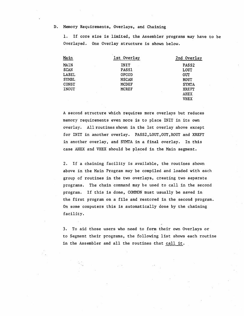
D. Memory Requirements, Overlays, and Chaining
1. If core size is limited, the Assembler programs may have to be
Overlayed. One Overlay structure is shown below.
Main 1st Overlay 2nd Overla:t
MAIN INIT PASS2 SCAN PASSI LOUT LABEL OPCOD OUT SYMBL MSCAN ROUT CONST MCDEF SYMTA INOUT MCREF XREFT
AHEX VHEX
A second structure which requires more overlays but reduces
memory requirements even more is to place INIT in its own
overlay. All routines shown in the 1st overlay above except
for INIT in another overlay. PASS2,LOUT,OUT,ROUT and XREFT
in another overlay, and SYMTA in a final overlay. In this
case AHEX and VHEX should be placed in the Main segment.
2. If a chaining facility is available, the routines shown
above in the Main Program may be compiled and loaded with each
group of routines in the two overlays, creating two separate
programs. The chain command may be used to call in the second
program. If this is done, COMMON must usually be saved in
the first program on a file and restored in the second program.
On some computers this is automatically done by the chaining
facility.
3. To aid those users who need to form their own Overlays or
to Segment their programs, the following list shows each routine
in the Assembler and all the routines ·that call it.

MAIN -INIT - MAIN INOUT - PASSl,PASS2,MCDEF,MCREF,ROUT,SYMTA,XREFT PASSl - MAIN PASS2 - MAIN OPCOD - PASSl,MCDEF LABEL - INIT,PASSl,SCAN SYMBL - PASSl,OPCOD,LABEL,MCDEF,MSCAN SCAN - PASSl,PASS2 CONST - SCAN MCDEF - PASSl MCREF - PASSl MSCAN - PASSl,MCDEF LOUT - PASS2 OUT - PASS2 ROUT - OUT SYMTA - MAIN XREFT - PASS2,LABEL,SYMTA VHEX - LOUT,ROUT AHEX - LOUT,SYMTA

E. Cross Reference
The cross reference table is accumulated in a memory array and when
the array is filled the table is stored on a disk file. However,
the variable IXPAG in subroutine INIT may be set to 0, in which case
if the m~~ory array becomes full, the table will not be written to
disk and further references will not be accumulated but assembly will
continue.
2. The standard cross reference tab1~ array size is 512 words.
Each reference requires 2 words, hence 256 references may be
accumulated in memory. To avoid using disk this array may be
increased. The variables to change are described below.
3. The number of reference table arrays (memory array of 512 words)
that will be written to disk is set at 25. Hence 256*25 references
can be accumulated with the standard program. This may also be
increased.
4. The disk file that is used to store cross references (if
necessary) is the same as the file used for macros. If necessary
for some reason, another file may be assigned. The cross reference
read and write statements in INOUT may then have to be changed.
5. To increase the page size (memory array) of the cross reference
table or total number of pages produced or to not use the disk to
store references, the following variables must be changed.
MXREF -
IXTAB -
IXPAG -
size of cross reference memory. The number of references
on a page is (MXREF/2) . MXR.EF should be divisible by 128.
cross reference array. Should be set to IXTAB (MXREF)
total number of pages of size MXREF that will be written
Q'efore accumulating references stops. If IXPAG=O then no
pages will be written to disk and references will only be
accumulated in memory.

F. NOVA Modifications
When installing the Assembler on a NOVA Computer, it is suggested
that Fortran V be used. If Fortran IV is used, some additional
program modificaitons have to be made.
1. Most versions of NOVA Fortran fill an H data specificaiton
sta tement :with zeros and not blanks, as is typically done.
Therefore, characters read in under A formats must have the padded
blanks stripped off. Insert the following statements after Fortran
Statement 100 in INOUT.
DO 105 1=1,80 IN(I) = IN(I).AND.-256
105 CONTINUE
2. All variables initialized in DATA statements must be placed
in Labeled COMMON. The variables are local to each Subroutine,
so unique dummy labels may be used for the COMMON Block names.
3. The DEFINE FILE statements in the Main program must be replaced
with CALL OPEN statements similar to those shown below.
CALL OPEN(7,"IDUMl",3,IER)
CALL OPEN(8,"IDUM2",3,IER,228)
The number of bytes per record must be included for random access
files.
4. The Assembler Macro file must be random access, so a call to
FSEEK must preceed each Macro and Cross Reference file access. Use
Binary READ and WRITE statements for the intermediate files. To
implement the above, change the Fortran source code in INOUT as follows:
200 READ BINARY (IMFLE) IMBUF
. 300 CALL FSEEK (MCFLE,MCREC) READ BINARY (MCFLE) MCBUF
400 CALL FSEEK (MCFLE,MCREC) READ BINARY (MCFLE) MCORE
500 WRITE BINARY (IMFLE) IMBUF
600 CALL FSEEK (MCFLE,MCREC) WRITE BINARY (MCFLE) MCBUF
700 CALL FSEEK (MCFLE,MCREC) WRITE BINARY (MCFLE) (IXTAB(J),J=1,128)

5. Several characters cannot be used in Hollerith Data Specifi
cations since they are not in the NOVA assembler's legal character
set. These include right and left parenthesis, percent signt
quote mark, question mark, etc •. Check you Assembly Language
Manual for the legal character set. The greater than and less
than sign are probably also illegal even though they are listed
as legal. In Subroutine INIT, replace all illegal characters
with their internal representations as they would appear in a
lH Data format.
DATA NALPH( l),NALPH( 2),NALPH( 3),NALPH( ~) 11H011HI11H2~lH31
DATA NALPH( 5),NALPHC 6)INALPH( 7),NALPH( 8) 11H411H5,1H6~lH71 DATA NALPH( 9)INALPH(10)INALPH(11),NALPH(12) 11H8,1H9~lHA~lHBI DATA NALPH(13)INAL?HC14)INALPH(l5),NALPHC16) IIHC,IHDIIHE~lHFI DATA NALPH(17)INALPH(18),NALPH(19)~NALPH(20) 11HG,IHH~IHl~lHJI DATA NALPH(21)INALPHC22)INALPHC23),NALPHC24) 11HKIIHLIIHM~lHNI DATA NALPH(25)INALPH(26)INALPH(27),NALPHC28) IIHOIIHPIIHQ~lHRI DATA NALPH(29)INALPHC30)INALPH(31),NALPH(32) 11HSIIHTIIHU~lHVI DATA NALPH(33)INALPHC34),NALPH(3S)INALPHC36) 11H~~IHXIIHYIIHZI DATA N~PH(37)INALPH(38),NALPH(39)INALPH(40) IlH ~lHI1870411H'1 DATA NALPH(41)~NALPH(42)INALPHC4~),NALPH(44) 1921619472~lH&~99841 DATA NALPH(45),NALPH(46)INALPH(47)INALPH(48) 110240~10496~IH*~lH+ DATA NALPH(49)INALPHC50),NALPH(5l)INALPHC52) IlHI~lH-llH.,lHII DATA NALPH(53)~NALPHC54),NALPH(55)INALPHC56) IlHIIIH1115360~lH=1 DATA NALPH(57)INALPH(58),NALPHCS9) Il5872116128,1HII DATA NBLNK,NQUOTINPLUSINMIN,NGRAT,NLESS
1 IIH 199841 IH+I IH-I 158721153601 DATA NDOLRINCOMMINASTINSEMIINCOLN/92161IHlllH.,IH1IIHII DATA NCHRAINCHRD,NCHRE,NCHRF,NCHRL 11HAIIHDIIHE~lHFIIHLI DATA NCHRM,NCHRO,NCHRRINCHRS,NCHRT IIHMllHO,IHRllHS,IHTI DATA NCHRU,NCHRV,NCHRB,NCHRX,NCHRW IIHUIIHVIIHBllHX,IHWI DATA NMULT,NDIV,NRPAR,NLPAR IIH.I.lH/I10496,102401 DATA NCPER,NCATINSHRP,NAMP 19472, IHII IHI,IH&I DATA NTITLC 1)INTITLC 2),NTITL( 3),NTITL( 4) IIH611H8,1H0,1H01 DATA NTITLC S),NTITLC 6),NTITL( 7),NTITLC 8) IIH IlHM,lHAllHCI DATA NTITLC 9),NTITL(10)INTITL(11),NTITLC12) IIHRlIHO,IH 11HAI DATA NTITL(13)INTITLCI4),NTITL(l5),NTITLC16) IIHS,IHSIIHE~lHMI DATA NTITLCI7)INTITLC18),NTITL(19),NTITLC20) 11HBIIHLI1HE~lHRI DATA NTITL(21)~NTITLC22)INTITL(23)iNTITL(24) 11H 11HVIIHE~lHRI


