61
831-INT & 831-INT-ET 831 Docking Station Manual

831-INT & 831-INT-ET831 Docking Station
Manual

I831.04 Rev H
Larson Davis 831-INT & 831-INT-ET
Docking Station
Manual

I831.04 Rev H
Copyright
Copyright 2017 by PCB Piezotronics, Inc. This manual is copyrighted, with all rights reserved. Themanual may not be copied in whole or in part for any use without prior written consent of PCBPiezotronics, Inc.
Disclaimer
The following paragraph does not apply in any state or country where such statements are notagreeable with local law:
Even though PCB Piezotronics, Inc. has reviewed its documentation, PCB Piezotronics, Inc. makes nowarranty or representation, either expressed or implied, with respect to this instrument anddocumentation, its quality, performance, merchantability, or fitness for a particular purpose. Thisdocumentation is subject to change without notice, and should not be construed as a commitment orrepresentation by PCB Piezotronics, Inc.
This publication may contain inaccuracies or typographical errors. PCB Piezotronics, Inc. willperiodically update the material for inclusion in new editions. Changes and improvements to theinformation described in this manual may be made at any time.
Record of Serial Number and Purchase Date
831-INT(-ET) Serial Number: ___________ Purchase Date: ___________
831-INT-ET MAC Address: ________________
Recycling
PCB Piezotronics, Inc. is an environmentally friendly organization and encourages our customers tobe environmentally conscious. When this product reaches its end of life, please recycle the productthrough a local recycling center or return the product to:
PCB Piezotronics, Inc.Attn: Recycling Coordinator1681 West 820 NorthProvo, Utah, USA 84601-1341
where it will be accepted for disposal
Warranty
For warranty information, refer to our Terms and Conditions of Sale on our websitewww.larsondavis.com/TermsConditions.aspx.
Chapter 1 Introduction 1-1
Overview............................................................................................................... 1-1
Features ............................................................................................................ 1-2
Standard Accessories ............................................................................................ 1-3
Optional System Accessories................................................................................ 1-4
Chapter 2 Assembly and Configuration 2-1
Electrical Connection Overview ........................................................................... 2-1
Battery Connection........................................................................................... 2-5
Router Battery Connection............................................................................... 2-7
Assembly Diagram................................................................................................ 2-9
Internal Jumpers .................................................................................................. 2-10
Battery Charger .............................................................................................. 2-11
Battery Temperature Sensor........................................................................... 2-11
Watchdog ....................................................................................................... 2-12
Embedded Computer Enable.......................................................................... 2-13
Fuses.................................................................................................................... 2-13
Placement of Model 831 ..................................................................................... 2-15
Mounting 831-INT in an EPS031 or EPS043..................................................... 2-16
Configuring Routers for 831-INT-ET................................................................. 2-17
Chapter 3 Operation 3-1
Status Indicators .................................................................................................... 3-1
Mains Power/External 15V DC Power ............................................................ 3-1
Battery Charger Status ..................................................................................... 3-2
System On Status ............................................................................................. 3-2
USB Status ....................................................................................................... 3-3
831-INT-ET Operation ......................................................................................... 3-3
Proper Shutdown Method................................................................................. 3-4
Connecting to Model 831 through 831-INT-ET using G4 LD Utility.................. 3-4
Connecting to Model 831 through 831-INT-ET using SLM Utility-G3 .............. 3-5
Battery Charger Operation .................................................................................... 3-6
Solar Power Operation .......................................................................................... 3-8
System SLA Battery Capacity and Run-time ....................................................... 3-8
Appendix A Technical Specifications A-1
Physical Characteristics ........................................................................................ A-1
Environmental Specifications ............................................................................... A-1
831-INT-ET Docking Station with Ethernet......................................................... A-3
I831.04 Rev H

USB HUB ............................................................................................................. A-3
Outdoor Microphone System................................................................................ A-3
Battery Charger..................................................................................................... A-5
Battery Connector................................................................................................. A-5
Logic I/O & Auxiliary Power Connector ............................................................. A-6
Power Specification .............................................................................................. A-8
Power Consumption for Model 831, 831-INT, 831-INT-ET and Accessories A-8
Mains Power .................................................................................................... A-9
PSA030 Power Adapter ................................................................................... A-9
Battery............................................................................................................ A-10
Internal Charger ............................................................................................. A-10
Other Electrical Characteristics ..................................................................... A-11
Appendix B Troubleshooting B-1
I831.04 Rev H

C H A P T E R
1 Introduction
This chapter summarizes the features and accessories of the831-INT and 831-INT-ET.
Overview
The information presented for the831-INT is applicable to both 831-INT and 831-INT-ET.
The Larson Davis 831-INT is a companion product to theModel 831 Sound Level Meter that adds functionalityneeded for outdoor noise monitors. The 831-INT-ETincludes functionality to support Ethernet communication.
It also enhances the capabilities of the Model 831 to includeinterfaces for components of a permanent noise monitoringsystem. Figure 1-1 shows the 831-INT-ET.
FIGURE 1-1 831-INT-ET
Introduction Overview 1-1

Features
Outdoor Microphone Preamplifiers
• Provides power and control signals for the 426A12 andPRM2103 outdoor microphone preamplifiers.
Battery Management
• Backup battery management and charge control.
• Connection for up to two 12 V sealed lead-acid (SLA)batteries using removable screw terminal connectors.
• Integrated multi-stage charger for SLA batteries.Efficient Switch-Mode Power Supply circuitry used toreduce heat and improve reliability.
• Automatic low battery shutdown prevents batterydamage.
• Automatic power up when battery is charged sufficientlyby Mains power or solar-powered charger.
Power Management
• Mains power with automatic switch over to batterypower when mains power fails.
• Support for solar power.
• LED Indicators:
1. Mains Power On.
2. Charger Status.
3. System Power Status, including shutdown status and low battery status.
4. USB Hub Power On.
• Mains power, provided by the PSA030 power supply.
• Automatic power up with Mains power restoration.
• Independent watchdog systems in both the Model 831meter and the embedded computer in the 831-INT-ETwill restart the system in the event of system fault.
• Quick SBC power on timing.
• USB hub power (and USB devices deriving power fromthe Hub) is turned on or off as needed by the Model 831for efficient power management.
USB Hub
• 4-port powered USB hub for peripherals.
1-2 Overview Introduction

• Directly power devices such as:
- SEN031: weather station.
- COM-RV50-DC-U/E: Wireless Ethernet Gateway.
- DVX011: USB to serial adapter.
- GPS001: GPS receiver.
Digital Input/Output
• 2 digital I/O control lines (1 in, 1 out).
Internet Connection
• 831-INT-ET provides an RJ45 Ethernet connector forbroadband, Internet connection. This provides:
- Faster communication speed.
- Remote firmware upgrade.
- Real-time streaming of data.
Mounting
• Compact design cradles the Model 831 and provides for mounting.
Standard Accessories
The 831-INT is delivered with the following accessories:
• PSA030: Power Supply.
• CBL159: USB A to Mini-B USB cable, (2 provided).
• 1/4"-20 x 5/8" Stainless Steel Thumb Screw with spacer and washer for mounting the 831-INT to a panel.
• Screw Driver.
• 5-position pluggable screw terminal, (2 provided).
• I831.04: 831-INT and 831-INT-ET User Manual.
Introduction Standard Accessories 1-3

Optional System Accessories
The 831-INT is an accessory of the Model 831 Sound LevelMeter that, when combined with the following accessories,form the core of a noise monitoring system.
Sound Level Meter
• Model 831: Sound Level Meter.
Outdoor Microphone Preamplifiers
• 426A12: Outdoor Microphone Preamplifier.
• PRM2103-FF Outdoor Microphone Preamplifier.
Environmental Enclosure
• EPS031: Small environmentally protected, pole mountable enclosure for AC mains power, with 9 AH battery, which supports the Model 831, 831-INT and accessories.
• EPS043: Large environmentally protected, pole mountable enclosure for AC mains power, with 9 AH battery, which supports the Model 831, 831-INT and accessories.
Sensors
• SEN031: Vaisala WXT520 multi-metric weather station.
GPS Receiver
• GPS001: GPS Receiver, provides location and time synchronization.
Communication Devices
• COM-RV50-DC-U/E: Raven XE G3 Ethernet Gatewaywith DC power cable.
Signal/Control Cables
• CBL152: Signal Cable, 426A12 to 831-INT, 20 ft (6m).
• CBL153: Control Cable, 426A12 to 831-INT, 20 ft (6m).
• CBL167: Cable for SEN031 weather station. Connects to the Model 831 through 831-INT with DVX008A.
Battery Cables
• CBL147: 831-INT Single Battery Connection, 2 ft (0.6m).
• CBL149: Cable 831-INT to Battery, 12 ft (3.7m).
1-4 Optional System Accessories Introduction

• CBL160: Cable connecting 831-INT to solar charger, 2 ft (0.6m).
• CBL161: Cable for 100 AH battery to solar charger, 10 ft. (3m).
Introduction Optional System Accessories 1-5

1-6 Optional System Accessories Introduction
C H A P T E R
2 Assembly and Configuration
This chapter provides the 831-INT assembly informationnecessary for configuring the device.
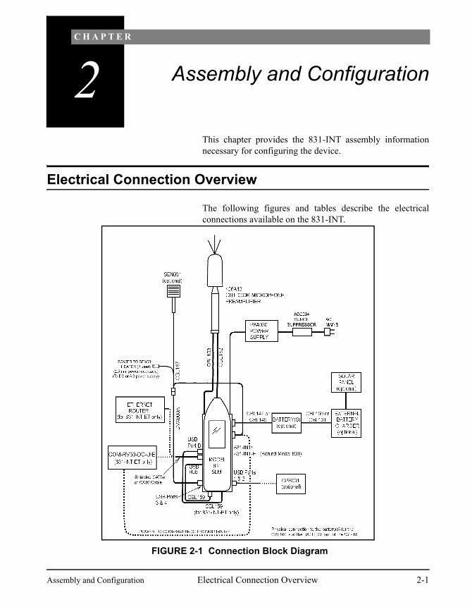
Electrical Connection Overview
The following figures and tables describe the electricalconnections available on the 831-INT.
FIGURE 2-1 Connection Block Diagram
Assembly and Configuration Electrical Connection Overview 2-1

FIGURE 2-2 831-INT with Model 831: Right Side View
831-INT Connector Usage Cable
USB PORTS 1 and 2 gateway, GPS Direct connect or USB Cable
AUX POWER & LOGIC I/O
Provides power for auxiliary devices, switch and indicator light, SEN031 Weather station, and Sierra Wireless RV50.
CBL167 for SEN031 weather station, otherwise user supplied.
EXTERNAL CHARGER External Battery Charger input, optional1
BATTERY One or two, 12-volt sealed lead acid batteries
CBL147 or CBL149. See “Battery Connection” on page 2-5
1In the event that a charger with more capacity is needed
Table 2-1 Connections to 831-INT or 831-INT- ET: Right Side
2-2 Electrical Connection Overview Assembly and Configuration

FIGURE 2-3 831-INT with Model 831: Top End View
Model 831 and 831-INT Usage Cable
Mains Power PSA030 15 VDC Power Supply Included with PSA030
Preamp Control 426A12 or PRM2103-FF Outdoor Microphone Preamplifier Control connector
CBL153 (426A12) or CBL208 (PRM2103-FF)
Model 831 Preamplifier (nose cone)
426A12 Outdoor Microphone Preamplifier Signal connector
CBL152 Signal Cable
Table 2-2 Connections to 831-INT and Model 831: Top End
Assembly and Configuration Electrical Connection Overview 2-3

FIGURE 2-4 831-INT-ET with Model 831: Left Side View
831-INT Connector Usage Cable
USB HUB INPUT Connect CBL159 between USB HUB INPUT and the Model 831 USB host connector labeled AUX
CBL159
USB Ports 3 and 4 SEN031 Weather Station, etc. CBL167 for SEN031 weather station
Table 2-3 Connections to 831-INT or 831-INT- ET: Left Side
2-4 Electrical Connection Overview Assembly and Configuration

Table 2-4 Connections available with 831-INT-ET
Battery Connection
There are two cables available for connecting the batteries tothe 831-INT.
Single Battery
The CBL147 is used with a single battery such as theBAT014, a 9 AH sealed lead acid battery. The CBL147 usesa 3AG 4A Slo-Blo Littelfuse (p/n 0313004.HXP).
FIGURE 2-5 CBL147
Underground Battery EPS035
The EPS035 is an underground vault/enclosure with a 100AH deep cycle sealed lead acid battery which is usually used
831-INT-ET Connector
Usage Cable
USB A Not used.
USB B Connect CBL159 between USB B and USB Connector on 831
CBL159
Ethernet Network Device CAT5e or CAT6 Shielded Network cable
Assembly and Configuration Electrical Connection Overview 2-5

with permanent solar powered installations. The CBL149,which is 12 feet long and has a remote battery temperaturesensor, is designed for use with this battery. The CBL149uses a 3AG 4A Slo-Blo Littelfuse (p/n 0313004.HXP.)Figure 2-6 shows CBL149.
.
FIGURE 2-6 CBL149
It is possible to utilize a temperature sensor inside the 831-INT instead of the temperature sensor included with the cable. See “Battery Temperature Sensor” on page 2-11. for further detail.
To achieve good performance and long battery life, thecharging of the battery can be optimized by monitoring thebattery temperature. Attach temperature sensor to the batteryby peeling off backing material and pressing adhesivecoated side of sensor to the side or top of the battery.
The 831-INT is delivered with internal temperature compensation enabled for use with CBL147.
Set the internal controls to use the External TemperatureSensor. See “Battery Temperature Sensor” on page 2-11 formore details.
Solar Charger Cables
The CBL160 is used to connect power between a solarcharger and the 831-INT. CBL161 is used to connect thesolar charger to the batteries.
2-6 Electrical Connection Overview Assembly and Configuration

FIGURE 2-7 CBL160 Cable to Solar Charger
FIGURE 2-8 CBL161 Cable 100 AH Battery to Solar Charger
Router Battery Connection
A Sierra Wireless RV50, GX450, and LS300 can beconnected to the 831-INT-ET as a power source by using aDC cable as shown in FIGURE 2-9 Router DC CableConnection. The Ethernet cable will need to be inserted tofinish the router’s connection to the 831-INT-ET.
Assembly and Configuration Electrical Connection Overview 2-7

FIGURE 2-9 Router DC Cable Connection
AUX POWER BATTERY
DCPower
2-8 Electrical Connection Overview Assembly and Configuration

Assembly Diagram
FIGURE 2-10 831-INT Exploded Assembly
Assembly and Configuration Assembly Diagram 2-9

Internal Jumpers
The 831-INT has jumpers that are used to enable or disable831-INT features, including the following:
• Watchdog timer for automatic reset if failure occurs
• External temperature sensor for improved batterycharging
• Built in lead acid battery charger
To gain access to these jumpers, do the following:
WARNING! Do not remove thepower from the 831-INT beforeproperly shutting down the Model831 and then waiting for the greenSYSTEM ON LED to stop flashing,see“Proper Shutdown Method” onpage 3-4
• Shut down the Model 831 and remove all cables,including the power cable.
• Remove the Model 831 from the 831-INT.
• While doing the rest of this operation, ensure to followgood electrostatic discharge (ESD) practices. First touchmetal that is known to be grounded. Then touch a baremetal part of the 831-INT before opening up the case.
• Remove the small rubber o-ring that is found on the longcaptured the Model 831 retaining screw.
• Remove retaining screw by pulling it out as far as it cango and then unscrewing it out of the top case.
• Remove the upper four screws of the 831-INT with aPhillips screw driver.
• Remove the 831-INT's upper cradle and top case metalpieces.
This gives access to the 831-INT's circuit boards.
When the assembly is put back together, take care to ensurethat the grounding tabs on the circuit board make contactwith the inside wall of the enclosure, and that these tabs donot get crushed or deformed in the process. It is helpful topush them into the enclosure with a screwdriver, whileplacing the top enclosure case on.
2-10 Internal Jumpers Assembly and Configuration

Battery Charger
When using solar power or an external charger, the internalcharger should be disabled.
Battery Temperature Sensor
The 831-INT supports temperature compensated chargingfor 12V sealed lead-acid batteries. An internal sensorprovides temperature compensation without physicallycontacting the battery and offers reasonable temperaturecompensation when the battery and the 831-INT are in closeproximity (in the same enclosure). For this internaltemperature compensation configuration use batteryconnector cable CBL147.
P4 Charger Enabled (default)Place P4 jumpers as shown to enable internal charger.
P4 Charger Disabled (optional)Remove the jumpers from both pin pairs of P4 to disable the internal charger. This will permit the use of an external charger or solar charger to directly charge the battery. Keep the jumpers in a secure place so that they are handy if operation needs to be changed later. They can be placed on the side pins for safe keeping (as shown below).
Table 2-5 Internal Battery Charger Enable
Assembly and Configuration Internal Jumpers 2-11

For batteries using the CBL 149, use the External BatteryTemperature Sensor configuration.
Watchdog
Caution: Remove the AA batteries from the Model 831 for proper functioning of the watchdog.
For a description of the watchdog function, see “WatchdogCycle Time:” on page A-12.
Table 2-7 Watchdog on 831-INT Circuit Board
P3 Internal Battery Temperature Sensor (default)Select the temperature sensor that is internal to the 831-INT by placing a jumper on the top pin pair of P3 as shown. The bottom jumper is a spare.
P3 External Battery Temperature Sensor (optional)Select the temperature sensor that is attached to the battery by placing a jumper on the middle pin pair of P3. The bottom jumper is a spare. Used with CBL149
Table 2-6 Select Battery Temperature Sensor
P2 Watchdog Enable (default)The watchdog will cycle the power to the Model 831 off and on in the event that the Model 831 stops responding to the 831-INT for a period of 12 minutes. The watchdog is enabled when the upper right pins of P2 are connected by a jumper as shown in the figure and the bottom right pin remains open.
P2 Watchdog DisableThe watchdog is disabled when the bottom right two pins are connected by a jumper and the upper right pin is open as shown in the figure.
2-12 Internal Jumpers Assembly and Configuration

Embedded Computer Enable
This jumper is factory set and should not requiremodification.
Table 2-8 Configuration for 831-INT/831-INT-ET
Fuses
All fuses listed below are Littelfuse p/n 0454003, Slo-Blo125V 3A or equivalent, unless otherwise noted.
• F2 - Preamplifier Fuse (Littelfuse 0453.500MR, very fastacting, 0.5 A, 125V)
• F6 - External Charger Fuse
• F7 - Fuse for battery #1
• F8 - Fuse for battery #2
• F9 - Fuse from mains power to primary circuit board andinternal SLA charger
• F10 - Fuse for Model 831, USB hub, and embeddedcomputer when configured for a 831-INT-ET
See FIGURE 2-11 for locations of these fuses on board.
P2 SBC in 831-INT-ET is enabled.
P2 No SBC unit (default) is configured as 831-INT.
Assembly and Configuration Fuses 2-13

FIGURE 2-11 831-INT Circuit board
2-14 Fuses Assembly and Configuration

Placement of Model 831
When properly inserted, the screw will align with the Model 831 battery door security nut.
The Model 831 slides in between the two vertical guideplates on the sides of the 831-INT as shown in FIGURE 2-12.
Caution: For proper watchdogoperation, remove the AA batterieswithin the Model 831.
FIGURE 2-12 Model 831 Placement
Hold the 831-INT in one hand, in such a manner that theretaining screw which will secure the Model 831 to the 831-INT drops into the retracted position below the uppersurface of the 831-INT.
With the other hand, slide the Model 831 between the twovertical guide plates, back end (with connectors) first andpress until the electrical connector on the end plate is alignedand inserted firmly into the I/O Connector of the Model 831.
From beneath the 831-INT, manually tighten the retainingscrew to secure the Model 831 firmly onto the 831-INT.
Removal of Model 831
Turn off the Model 831 prior to disconnecting from the831-INT.
When removing the Model 831 from the 831-INT, theModel 831 must be kept out of the cradle for at least 5 - 10seconds before re-inserting to have the automatic power-onfeature work properly.
Assembly and Configuration Placement of Model 831 2-15

Mounting 831-INT in an EPS031 or EPS043
A 1/4-20 x 5/8” stainless steel thumb screw with spacer andwasher is provided with the 831-INT for mounting it to apanel. Screw into the threaded insert on the back of the 831-INT as shown in FIGURE 2-13. Ensure that the convex sideof the curved washer is facing towards the 831-INT.
FIGURE 2-13 Placement of Stainless Steel Mounting Hardware
The 831-INT is then suspended from a mounting platewhich has a key hole at the top to engage the thumb screw asshown in FIGURE 2-14. When the 831-INT is positionedproperly, tighten the thumb screw securely.
FIGURE 2-14 Mounting of 831-INT
2-16 Mounting 831-INT in an EPS031 or EPS043 Assembly and Configuration

Configuring Routers for 831-INT-ET
Overview
The 831-INT-ET enables the Model 831 to communicateusing broadband network technology.
The 831-INT-ET is designed to be placed on a privatenetwork with access to the Internet through a router. The831-INT-ET ships pre-configured to support DHCPaddressing, allowing the 831-INT-ET to work in a typicalprivate network. To allow the 831-INT-ET to be accessiblefrom the Internet, port forwarding needs to be set up in therouter and the DHCP server configured to provide a reservedaddress to the 831-INT-ET. You will also need to configureyour firewall to allow the required ports.
Proper installation will require someone familiar with router,DHCP, and firewall configuration, who also hasadministrative rights for these devices.
Assembly and Configuration Configuring Routers for 831-INT-ET 2-17

Configuration
A typical network configuration is shown in Figure 2-15.
FIGURE 2-15 Typical Network Configuration
2-18 Configuring Routers for 831-INT-ET Assembly and Configuration

Viewing the Private IP Address
If the DHCP is not found, see “TheIP Address on Model 831 is notshown.” on page B-6.
You can view the private IP address of the Model 831 whenconnected to the 831-INT-ET by pressing the Tools buttonon the meter and selecting Communications. Figure 2-16shows the Network tab in Communications:
The private IP address shown on themeter is not automatically mapped tothe public IP address for yourorganization’s network; therefore,network connectivity will require theassistance of your IT professional.
FIGURE 2-16 Private IP Address
Router Configuration
The 831-INT-ET MAC address is needed to configure therouter for DHCP. The MAC address is located on the backlabel of the 831-INT-ET (see FIGURE 2-17). Afterconfiguring the router for the 831-INT-ET, use the IPaddress or host name and port number that is needed in orderto connect the G4 LD Utility software to the Model 831through the 831-INT-ET via Ethernet. For properfunctionality, configure the router as follows:
1. Use a static IP address for the Internet side of the router. This is the address to which you will communicate with the Model 831 using G4 LD Utility or other software. To get a static IP address, request one from your net-work service provider.
Assembly and Configuration Configuring Routers for 831-INT-ET 2-19

2. The private side of the router should support DHCP. This is a common feature found on almost all routers. If devices other than the 831-INT-ET are connected to the client side of the router, the DHCP server in the network adapter should be configured to always provide the same IP address to the 831-INT-ET. This is done by configuring a reserved IP address for the MAC address found on the label on the 831-INT-ET.
For Secure Sockets Layer (SSL)security, use TCP/IP port 443, whichrequires a password.
3. The router needs to be configured to port forward from the static address (Internet side) to the 831-INT-ET. The default TCP/IP ports are 2001, 80, or 443, which need to be forwarded and also allowed through any existing firewall.
FIGURE 2-17 831-INT-ET MAC Address
2-20 Configuring Routers for 831-INT-ET Assembly and Configuration

C H A P T E R
3 Operation
This chapter provides a description for properly operatingthe 831-INT with the Model 831 sound level meter.
Status Indicators
When operating the 831-INT andModel 831 sound level meter, ensurethat the meter is properly shut downbefore disconnecting power from the831-INT. Otherwise, the resultingimproper shutdown may corrupt theflash memory in the Model 831 or831-INT-ET.
The 831-INT provides four LEDs to indicate status. Theyare as follows:
• Mains Power (MAINS PWR)
• Battery Charger Status (CHARGE)
• System On Status (SYSTEM ON)
• USB Status (USB HUB)
Figure 3-1 shows the location of the status indicators.
FIGURE 3-1 LED Status Indicators
Mains Power/External 15V DC Power
The green MAINS PWR LED is illuminated when theexternal supply is greater than 13.8 volts. Connect thePSA030 power supply to the Mains Power connector topower the 831-INT, an attached Model 831, and chargeoptional batteries. The mains or battery voltage can be readon the Model 831 display (refer to the Model 831 Manual).
MAINS PWR
CHARGE
USB HUB
SYSTEM ON
Operation Status Indicators 3-1

Disconnecting 831-INT from the Model 831
Shut off the instrument properly. Animproper shut down or abrupt powerloss can result in corrupted ordamaged flash memory.
Turn off the Model 831 prior to disconnecting the 831-INTfrom the Model 831.
Battery Charger Status
The Model 831 internal battery charger status is indicated bythe red CHARGE status LED, shown in FIGURE 3-1:
• Illuminated, steady: Rapid charging
• Illuminated, winking: Float charging
• Slow flashing: Low battery recovery
• Fast flashing: Fault, thermistor or no battery
• Not Illuminated: Charger Off
System On Status
WARNING! When turning off theModel 831 sound level meter, waituntil the green SYSTEM ON LEDhas finished flashing quickly and hasturned off before disconnectingpower from the 831-INT. See“Proper Shutdown Method” onpage 3-4.
The green SYSTEM ON status LED indicates the system issupplied with power either by the battery or by the MainsPower connector.Table 3-1 indicates the states for this LED:
Instrument LED Indication State
831-INT ON, with two blinks per meter heart-beat
On with normal power
831-INT-ET ON, with alternating fading and brightening, according to the pace of heartbeats from the meter or SBC**
On with normal power
3-2 Status Indicators Operation

**The number of minutes since the last heartbeat from either the Model 831 or the SBC deter-mines the number of seconds that the LED stays on in this mode before fading. For example, a heartbeat once per minute is indicated by the LED staying lit one second before fading.
Table 3-1 System On LED States
USB Status
When the USB Host port is On, the green USB HUB LEDshown in FIGURE 3-1 will be illuminated.
The USB Host port power is controlled by the Model 831.See the Model 831 manual for more details.
831-INT-ET Operation
WARNING!Connect all cables to the 831-INT-ET prior to powering ON.
The SBC in the 831-INT-ET will boot up with the followingsequence:
1. The green SYSTEM PWR LED will turn on.
831-INT or 831-INT-ET
Flashing quickly Model 831 has been turned off and SBC is shutting down (do not disconnect power in this state)
831-INT or 831-INT-ET
Flashing quickly for two minutes
Power shut off is imminent due to watchdog
831-INT or 831-INT-ET
Flashing quickly Low battery shut off is imminent
831-INT or 831-INT-ET
Flashes once every second
Forced power off
831-INT or 831-INT-ET
Flashes once every four seconds
Model 831 and SBC are in normal power off
831-INT or 831-INT-ET
Flashes once every eight seconds
Low battery shutoff (will turn on when battery recov-ers 12.5 V or more or if mains power is connected)
Instrument LED Indication State
Operation 831-INT-ET Operation 3-3

2. If mains power is being used, the green MAINS PWR LED will turn on.
3. The Ethernet status LED's (green and orange) will initially be off, but will eventually come on and stay on. They will flicker at the presence of data traffic.
4. A few minutes after power on, the SBC will be ready for remote communications to the Model 831 through Ethernet connections.
Proper Shutdown Method
If the 831-INT-ET is not properly shut down, damage mayoccur to the system. To shut down safely, follow these steps:
Step 1 Power Off the Model 831.
Step 2 Red mains power LED will turn on.
Step 3 Wait until the red mains power LED light goes dark.
Step 4 You can now disconnect the 831-INT-ET or cables safely.
Connecting to Model 831 through 831-INT-ET using G4 LD Utility
To establish a TCP/IP type connection from G4 LD Utility(G4) software to the Model 831 through the 831-INT-ET,follow these steps:
For information on the 831-INT-ET’sIP Address see “ConfiguringRouters for 831-INT-ET” on page 2-17
Step 1 Connect a router via Ethernet cable to the 831-INT-ET.
Step 2 Power the Model 831 ON.
Step 3 Launch G4 LD Utility on a PC, click Connect.
Specify port numbers 80 or 2001. Ifusing Secure Sockets Layer (SSL)security, enter port number 443,which requires a password.
Step 4 Select 831 and TCP/IP options. Then press Add Meter, a new empty meter line will appear. See FIGURE 3-2 "G4 LD Utility Connect to Meter"
Step 5 Enter the following information into the row:
3-4 Connecting to Model 831 through 831-INT-ET using G4 LD Utility Operation

• Name (not required)
• IP Address
• Port number
• Password (if applicable)
Step 6 Click Connect.
FIGURE 3-2 G4 LD Utility Connect to Meter
Connecting to Model 831 through 831-INT-ET using SLM Utility-G3
To establish a TCP/IP type connection from the SLMUtility-G3 software to the Model 831 through the 831-INT-ET, follow these steps:
Step 1In SLM Utility-G3, click Connection > Remote > Internet. This will bring up the Remote Internet Site connection box. (See FIGURE 3-3.)
Step 2 Enter the host name of the router or the public IP address for the 831-INT-ET IP address and also the port number. When configured as described in this manual, the IP address or host name of the Model 831 is the public address of the router. For more information on this see “Configuring Routers for 831-INT-ET” on page 2-17.
Operation Connecting to Model 831 through 831-INT-ET using SLM Utility-G3 3-5

Refer to the SLM Utility-G3 Manualfor more information on its variousoperations and functions.
Step 3 Click Connect. This will connect SLM Utility-G3 to the Model 831 through TCP/IP.
FIGURE 3-3 Remote Internet Site Connection Box using Remote Site Host Name
Battery Charger Operation
The 831-INT battery charger is designed to automaticallycharge an 12V external sealed lead acid battery. The fourcharger modes and the red CHARGE LED operation areshown in Table 3-2.
3-6 Battery Charger Operation Operation

The CHARGE LED indicates sensortemperature by the duration itremains on between blinks. At 0 °C(32 °F), the LED remains on for 5seconds; at 25 °C (77 °F), the LEDremains on for 3 seconds, and at 60°C (140 °F), the LED remains on for1 second.
Mode/Status Indication
Table 3-2 Charger Mode/LED Indication
If the battery becomes drained, the Model 831 will shut offand the 831-INT will discontinue supplying power toperipherals to protect the battery and enhance service life.
The time that it takes to fully charge a battery using the 831-INT can be estimated from the following equation:
T=1.6xC
where
The 1 Ampere charge available fromthe 831-INT can charge batterieswith total capacities up to 42 AH.For batteries with higher capacitiesthan this, an external charger shouldbe used and the internal chargerdisabled (the PSA030 will still beused to power the system from MainsPower). See “Battery Charger” onpage 2-11 for additional detail.
T is time in hours
C is battery capacity in Ampere Hours (AH)
For instance, a 42 AH battery would take 1.6 x 42 = 67.2hours to fully charge.
Battery Matching
It is important when using dual batteries to ensure that theyare of the same make, model, charge level and age. Toensure that new batteries are at the same charge level youcan:
• Charge each battery individually and then put them in-service together. (This is the preferred method.)
• Install the first battery.
Charger Mode
Charge LED (Red)
Off: Disabled, or no mains power
Off
Rapid Charge On
Float Charge On, winking once every few seconds
Low Battery Recovery
Slow flashing
Fault, thermistor, or no battery
Fast Blinking
Operation Battery Charger Operation 3-7

• Charge the first battery until the charge status indicates float mode.
• Disconnect the first battery.• Install the second battery.• Charge the second battery until the charge status
indicates float mode.• Reinstall the first battery with the second battery
as they are now matched in charge.
• Measure the voltage of the two individual batteries. Ifthey are within 1/2 volt of each other they may beinstalled at the same time.
Solar Power Operation
For more information on externalbattery shutoff, see the Model 831Manual.
The 831-INT has provisions to work with solar power. Thesolar charger connects directly to the battery and the batteryconnects to the BATTERY connector of the 831-INT. Toprotect the battery, the system will shut off if the batterybecomes discharged. This shut-off voltage defaults to 10.8VDC, but can be programmed in the Model 831 settings.When the battery voltage reaches 12.5 VDC for at least twominutes, the system will automatically power on.
In the event that the system was powered off because of alow battery, the user can manually power up the system bypulling out the battery connector to the 831-INT for 30seconds and then plugging it back in. This can be done aslong as the battery voltage is greater than 10.8 volts.
System SLA Battery Capacity and Run-time
In the event that the mains power is lost to the 831-INT orwhen the solar charging system is not supplying adequatepower to the 831-INT, the 831-INT will switch to backupSLA batteries. To roughly estimate the total system batteryrun-time off this SLA battery, one needs to first calculate thetotal system power requirement. The power consumptions ofthe various system devices involved are listed in Table A-4'Device Power Consumption'. After summing the totalsystem power, to find the battery run-time approximation,use the equation:
Battery run-time = (C x 12.0 x 0.8) / Total System Power
3-8 Solar Power Operation Operation
C is the total batteries capacity in amp-hours.12.0 is the nominal voltage of the batteries.The 0.8 factor is a safety margin multiplier.
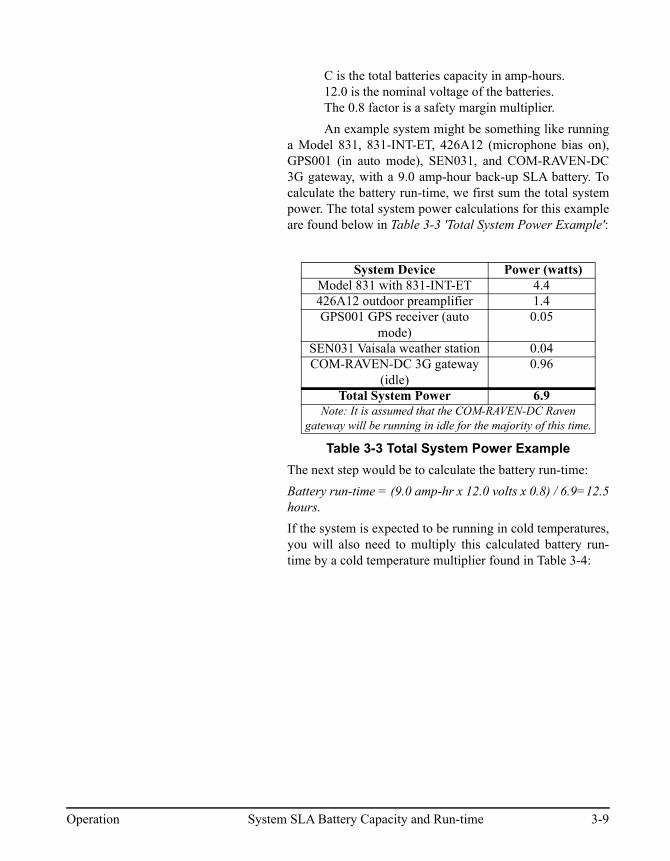
An example system might be something like runninga Model 831, 831-INT-ET, 426A12 (microphone bias on),GPS001 (in auto mode), SEN031, and COM-RAVEN-DC3G gateway, with a 9.0 amp-hour back-up SLA battery. Tocalculate the battery run-time, we first sum the total systempower. The total system power calculations for this exampleare found below in Table 3-3 'Total System Power Example':
Table 3-3 Total System Power Example
The next step would be to calculate the battery run-time:
Battery run-time = (9.0 amp-hr x 12.0 volts x 0.8) / 6.9=12.5hours.
If the system is expected to be running in cold temperatures,you will also need to multiply this calculated battery run-time by a cold temperature multiplier found in Table 3-4:
System Device Power (watts)Model 831 with 831-INT-ET 4.4426A12 outdoor preamplifier 1.4GPS001 GPS receiver (auto
mode)0.05
SEN031 Vaisala weather station 0.04COM-RAVEN-DC 3G gateway
(idle)0.96
Total System Power 6.9Note: It is assumed that the COM-RAVEN-DC Raven
gateway will be running in idle for the majority of this time.
Operation System SLA Battery Capacity and Run-time 3-9

Table 3-4 Battery Run-time Temperature Multipliers
So, if the above example system were to run at a possibleextreme temperature of -20 °C, the backup battery run-timewould be:
12.5 x 0.65 = 8.1 hours.
Battery lifespan will be dependent on what extent the batteryis being discharged. If the SLA battery is being used in abackup type application, the typical battery life span isapproximately three to five years.
For more information, see Lifecycleinformation from Power-Soniccorporation’s publication entitledSealed Lead-Acid BatteriesTechnical Manual.
If the battery is being used in a cyclical discharge scenario(i.e. solar powered system), the battery lifespan can varyaccording to what depth the battery is discharged to. Forexample, if the battery is being discharged 100% of thecapacity each cycle, a typical battery will only be able to becycled approximately 200 times. Cycling it down by 50%would give approximately 500 cycles. Cycling it down byonly 30% would give approximately 1000 cycles.
If the system is being charged by solar panels, other factorscome into play such as solar panel power output, location'slatitude, time of year, amount of sun exposure per day, etc.
Temp (°C) Battery Run-time Multiplier
21 1.0
10 0.90
0 0.85
-10 0.75
-201 0.65
-30 0.531Note: Many SLA batteries (including those sold with the Larson Davis noise monitoring systems) can be dis-charged at temperatures above -40 °C, but can only be charged at temperatures above -20 °C.
3-10 System SLA Battery Capacity and Run-time Operation

A P P E N D I X
A Technical Specifications
The specifications contained in this chapter are subject to change without notice.
Physical Characteristics
Length:
7.68" (19.5 cm)
Width:
3.00" (7.62 cm)
Height:
3.02" (7.66 cm)
Weight:
831-INT: 16.4 oz (465g)
831-INT-ET: 17.5 oz (496g)
Environmental Specifications
Operating Temperature:
- 40 °C to 70 °C
Storage Temperature:
- 40 °C to 70 °C
Humidity:
10 to 95% RH, non-condensing
831-INT and 831-INT-ET Manual Technical Specifications A-1

FIGURE A-1 831-INT Dimensional Drawing
A-2 Technical Specifications 831-INT and 831-INT-ET Manual
831-INT-ET Docking Station with Ethernet
The 831-INT-ET adds Ethernet communication capability to all features present in the 831-INT. The831-INT-ET contains the following additional features:
• Embedded computer.
• Ethernet connector.
• Additional USB Ports A and B. Use USB Port B to connect to the Model 831 USB Port.
• Expanded watchdog functionality. If USB communication between the 831-INT-ET and Model831 is lost for more than 5 minutes the complete system will restart.
USB HUB
• Powered, providing up to 500 mA per output port
• Hub Input Connector: Standard 5-pin mini-B Jack
• Four Hub Output Connectors: Standard USB-A Host Jacks. USB ports 1 through 4.
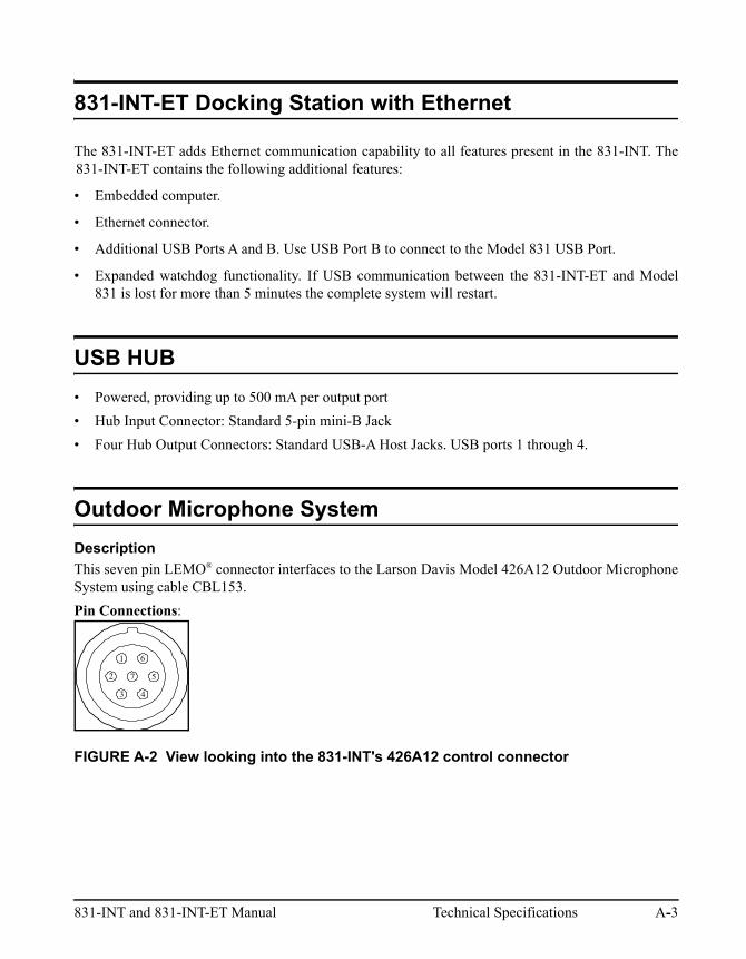
Outdoor Microphone System
Description
This seven pin LEMO® connector interfaces to the Larson Davis Model 426A12 Outdoor MicrophoneSystem using cable CBL153.
Pin Connections:
FIGURE A-2 View looking into the 831-INT's 426A12 control connector
1
2
3 4
57
6
831-INT and 831-INT-ET Manual Technical Specifications A-3
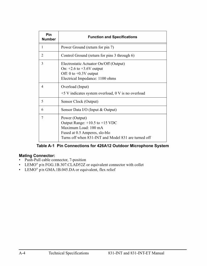
Mating Connector:• Push-Pull cable connector, 7-position• LEMO® p/n FGG.1B.307.CLAD52Z or equivalent connector with collet• LEMO® p/n GMA.1B.045.DA or equivalent, flex relief
Pin Number
Function and Specifications
1 Power Ground (return for pin 7)
2 Control Ground (return for pins 3 through 6)
3 Electrostatic Actuator On/Off (Output)On: +2.6 to +3.6V outputOff: 0 to +0.3V outputElectrical Impedance: 1100 ohms
4 Overload (Input)
+5 V indicates system overload, 0 V is no overload
5 Sensor Clock (Output)
6 Sensor Data I/O (Input & Output)
7 Power (Output)Output Range: +10.5 to +15 VDCMaximum Load: 100 mA Fused at 0.5 Amperes, slo-bloTurns off when 831-INT and Model 831 are turned off
Table A-1 Pin Connections for 426A12 Outdoor Microphone System
A-4 Technical Specifications 831-INT and 831-INT-ET Manual
Battery Charger
Description
This input provides an alternate means to charge batteries when the internal charger is disabled. Themains power input can be used to power the system, when mains power is available, so this externalcharger will only charge batteries. This input is connected directly to the battery terminals throughfuses and provides for optional alternative battery charging. A solar charge control can be attached tothis connector or, preferably, directly connected to the batteries.
Pin Connections:
Center Pin is positive battery DC voltage
Sleeve is Ground
Mating Connector:
Power Plug, 2.5 mm x 5.5 mm x 9.5 mm
Fuse
Fuse-protected at 3 Amperes, slow blow
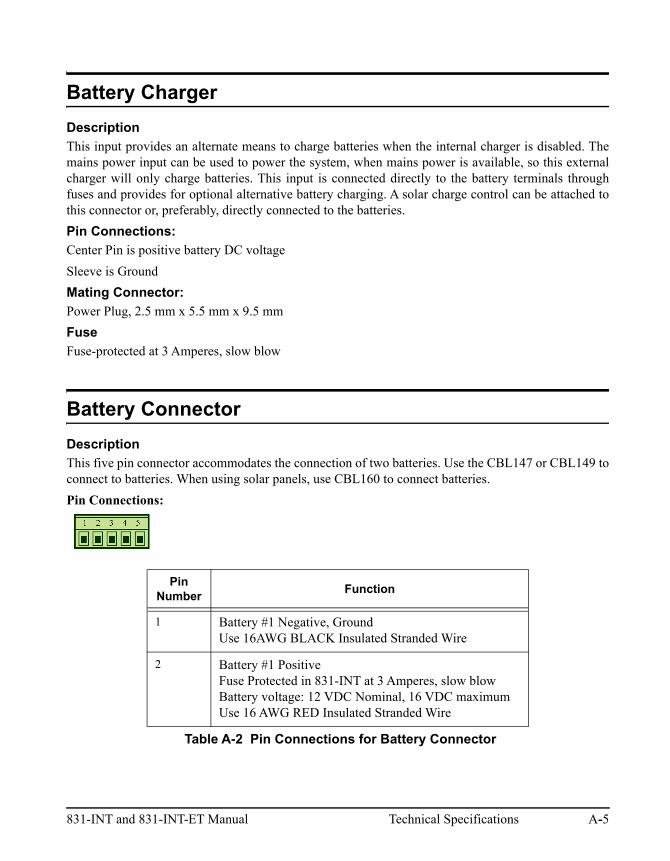
Battery Connector
Description
This five pin connector accommodates the connection of two batteries. Use the CBL147 or CBL149 toconnect to batteries. When using solar panels, use CBL160 to connect batteries.
Pin Connections:
Pin Number
Function
1 Battery #1 Negative, GroundUse 16AWG BLACK Insulated Stranded Wire
2 Battery #1 PositiveFuse Protected in 831-INT at 3 Amperes, slow blowBattery voltage: 12 VDC Nominal, 16 VDC maximumUse 16 AWG RED Insulated Stranded Wire
Table A-2 Pin Connections for Battery Connector
831-INT and 831-INT-ET Manual Technical Specifications A-5

Mating Connector for battery and also for logic I/O AUX Power Connector:
Pluggable Screw Terminal, 5-position
PHOENIX CONTACT p/n 1803604
16 to 28 AWG Wire Size
Larson Davis part number: 6200.0008
Logic I/O & Auxiliary Power Connector
Description
This five pin connector provides connections for Logic Output and Logic Input control lines, +5 voltoutput and switched battery power for auxiliary devices.
Pin Connections:
3 Temperature Probe Input100 k ohm thermistor, negative temperature coefficientConnect thermistor from pin 2 to pin 3 (battery +)Recommended device: BC COMPONENTS p/n: 2322 633 83104 (leaded part) or p/n: 2322 633 53104 (surface mount part)Must be thermally connected to battery
4 Battery #2 PositiveFuse Protected inside 831-INT at 3 Amperes, slow blowBattery voltage: 12 VDC nominal, 16 VDC maximumUse 16 AWG RED Insulated Stranded Wire
5 Battery #2 Negative, Ground Use 16 AWG BLACK Insulated Stranded Wire
Pin Number
Function
1 Ground
Table A-3 Pin Connections for Logic I/O and Auxiliary Power Connector
Pin Number
Function
Table A-2 Pin Connections for Battery Connector
A-6 Technical Specifications 831-INT and 831-INT-ET Manual

2 Logic OutputOpen drain transistor outputCapable of sinking 500 mA (maximum)Voltages up to +16 VDCOn resistance less than 2to groundMay be used to switch on Light-Emitting-Diodes (LED) or relays (solid-state or mechanical with protective reverse cur-rent diode)Power for LED lamps may come from pin 4
3 Logic Input+5 Volt active high input, 0 for de-assertedMay be a switch from pin 425 k resistor to ground input load
4 Auxiliary +5 Volt Supply Output+5 Volt for Logic Input switches or Logic Output LED power250 current limiting resistor
5 Auxiliary Power Supply Output+10.8 to +15 VDC to power auxiliary devices200 mA maximum loadSelf resetting fuse rated at 0.5 A (@ 25 °C)Turns off when 831-INT and Model 831 are turned off
Pin Number
Function
Table A-3 Pin Connections for Logic I/O and Auxiliary Power Connector
831-INT and 831-INT-ET Manual Technical Specifications A-7

Power Specification
Power Consumption for Model 831, 831-INT, 831-INT-ET and Accessories
Table A-4 Device Power Consumption
See System SLA Battery Capacity and Run-time on page 3-8 for more information on powerconsumption of other related system equipment and peripherals, total system consumption and alsobackup battery capacity required.
Device Power (Watts)
Model 831 0.92
Model 831 with 831-INT 1.2
Model 831 with 831-INT-ET 4.40
PRM831 Microphone Preamplifier 0.22
Model 426A12 Outdoor Preamplifier (no mic bias)
1.0
Model 426A12 Outdoor Preamplifier(with 200 V mic bias)
1.4
GPS001 GPS Receiver (Auto) 0.05
GPS001 GPS Receiver (On, not auto) 0.50
SEN031 Vaisala Weather Station 0.04
MDMUSB-A Dial-up modem 0.90
COM-RAVEN-DC Raven XE gateway (idle) 0.96
COM-RAVEN-DC Raven XE gateway (trans-mitting)
1.50
Model 831 USB host enabled 0.30
831-INT/831-INT-ET USB hub enabled 0.30
Note: Consumption values are typical with system voltage at 12 volts.
A-8 Technical Specifications 831-INT and 831-INT-ET Manual

Mains Power
Description:
The mains power input on the 831-INT and provides power to charge batteries when using the internalcharger, and to run the Model 831 with USB devices.
Pin Connections:
Center Pin is +15 VDC, absolute maximum is +16 VDC
Sleeve is Ground
Mating Connector:
Power Jack, 2.1 mm x 5.5 mm x 9.5 mm
Fuse:
Fuse Protected by two 3 Amperes, slow blow fuses; one for charger and one for system operation
PSA030 Power Adapter
Larson Davis part number PSA030 power adapter is supplied with the Model 831-INT and has thefollowing specifications:
INPUT
AC Input Voltage Rating:
100 to 240 VAC
AC Input Frequency:
47 to 63 Hz
Input Current:
1.2 A (rms) max. @ 115 VAC
OUTPUT:
Voltage:
15.0 VDC
Load Current:
0 to 3.2 A
Over Voltage Protection:
110-170% Vnom, Recycle input to reset
Over-current Protection:
110-170%, auto recovery
831-INT and 831-INT-ET Manual Technical Specifications A-9

Battery
One or two sealed-lead-acid (SLA) batteries may be used with the Model 831-INT.
Voltage:
12 volts Nominal
Typical Battery Configurations:
9 Ampere Hour, 12V Battery, LD p/n BAT014
2 x 21 Ampere Hour, 12V Batteries for a total of 42 AH, (two of LD p/n BAT011)
Minimum Recommended Capacity:
9 Ampere Hour
Terminals:
¼" male disconnect tab or bolt on adapter
Maximum Load:
Limited by 3 Ampere fuse per battery
Internal Charger
Triple Mode Charger:
1 Ampere rapid charge mode, followed by float charge mode, with Trickle charge for deeplydischarged batteries utilizing 1 A maximum charge pulses.
Rapid Charge Initiation Voltage:
VBattery 10.8 to 12.0 volts with temperature compensation
Rapid Charge Termination Voltage:
VBattery greater than 14.3 volts
Note: The 1 Ampere charge available from the 831-INT can charge batteries with total capacities upto 42 AH. For batteries with higher capacities than this, an external charger should be used and theinternal charger disabled (the PSA030 will still be used to power the system from Mains Power). SeeBattery Charger on page 2-11 and Battery Charger Operation on page 3-6 for additional detail.
A-10 Technical Specifications 831-INT and 831-INT-ET Manual

Float Charge Voltage:
13.8 volts, nominal at room temperature with temperature compensation.
FIGURE A-3 Charger Temperature Compensation
Temperature Sensor:
Internal: used when battery is in same enclosure
External: mounts directly to battery for greater accuracy
Trickle Charge Mode:
Activated when VBattery is less than 10.8 volts
Deactivated when VBattery is greater than 12.0 volts
Other Electrical Characteristics
Battery Low, Shut-off Voltage:
10.8 volts (adjustable setting in the Model 831).
831-INT and 831-INT-ET Manual Technical Specifications A-11

Switches from Mains to Battery Power when Mains voltage < 13.86 volts (battery must be sufficientlycharged to operate the system).
Watchdog Cycle Time:
The 831-INT monitors the activity status of the Model 831. If no activity is sensed for 12 minutes, itwill power-off the Model 831 and 831-INT for 15 seconds, after which time it will turn the power backon. It will repeat this cycle until the activity status indicates the Model 831 is operating again.
When using an 831-INT-ET there is a second watchdog monitoring the SBC. If no activity is sensed, itwill behave in the same manner as the first watchdog.
NOTE: Remove the AA batteries from the Model 831 in order for the watchdog to function properly.
A-12 Technical Specifications 831-INT and 831-INT-ET Manual

A P P E N D I X
B Troubleshooting
When I press the power button on my Model 831, the Model 831 does not turn on.
• If powered with mains power and the MAINS PWR status light on the 831-INT or 831-INT-ET islit:
○Verify that the Model 831 is seated into the 831-INT, and the 831-INT retaining screw (FIG-URE 2-10) is securing the Model 831 to the 831-INT.
○Ensure Model 831 hardware power switch is in ON ('|') position.
FIGURE B-1 Model 831 Bottom view
• If powered with mains power and the MAINS PWR status light is not lit:
○Ensure that the PSA030 power supply is plugged into AC mains and to the 831-INT MAINSPOWER connector.
○Check to see if indicator light on PSA030 power supply is on.
• My 831-INT is configured for solar power or battery operation:
○Check battery connections and voltage.
831-INT and 831-INT-ET Manual Troubleshooting B-1

○Battery voltage must be greater than 12.5V for Model 831 to turn on automatically, observestatus light on external or solar battery charger to see if the battery is being fully charged.
• If Model 831 still does not turn on, call customer support for further assistance.
During a power outage, my Model 831 or 831-INT does not continue operating.
• Check that the connections to the batteries and the 831-INT are correct.
• Verify the SLA batteries are being fully charged by checking the Battery Charger Status light onthe 831-INT. This light will be flashing if the battery is not connected.
• Determine if batteries have exceeded normal service life and replace if needed.
• Check fuses.
• If Model 831 and 831-INT still does not turn on, call customer support for further assistance.
My solar charger does not charge my batteries.
• Check for and remove obstructions that will shade the solar panel.
• Check indicators on solar charger.
• Determine if batteries have exceeded normal service life and replace if needed.
• Call customer support for further assistance.
I cannot connect G4 LD Utility to the Model 831 and 831-INT-ET using an Ethernet connection.
FIGURE B-2 Ethernet Status Lights and Ethernet PWR Light
Step 1 Check with your IT professional or broadband service provider to verify that the network router is functioning properly and port forwarding rules are entered correctly.
B-2 831-INT and 831-INT-ET Manual
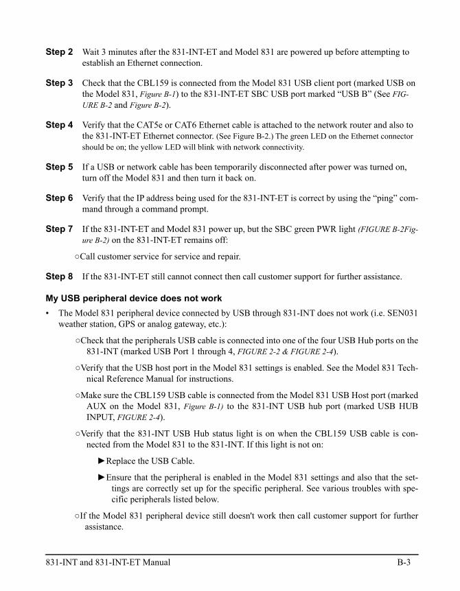
Step 2 Wait 3 minutes after the 831-INT-ET and Model 831 are powered up before attempting to establish an Ethernet connection.
Step 3 Check that the CBL159 is connected from the Model 831 USB client port (marked USB on the Model 831, Figure B-1) to the 831-INT-ET SBC USB port marked “USB B” (See FIG-URE B-2 and Figure B-2).
Step 4 Verify that the CAT5e or CAT6 Ethernet cable is attached to the network router and also to the 831-INT-ET Ethernet connector. (See Figure B-2.) The green LED on the Ethernet connector should be on; the yellow LED will blink with network connectivity.
Step 5 If a USB or network cable has been temporarily disconnected after power was turned on, turn off the Model 831 and then turn it back on.
Step 6 Verify that the IP address being used for the 831-INT-ET is correct by using the “ping” com-mand through a command prompt.
Step 7 If the 831-INT-ET and Model 831 power up, but the SBC green PWR light (FIGURE B-2Fig-ure B-2) on the 831-INT-ET remains off:
○Call customer service for service and repair.
Step 8 If the 831-INT-ET still cannot connect then call customer support for further assistance.
My USB peripheral device does not work
• The Model 831 peripheral device connected by USB through 831-INT does not work (i.e. SEN031weather station, GPS or analog gateway, etc.):
○Check that the peripherals USB cable is connected into one of the four USB Hub ports on the831-INT (marked USB Port 1 through 4, FIGURE 2-2 & FIGURE 2-4).
○Verify that the USB host port in the Model 831 settings is enabled. See the Model 831 Tech-nical Reference Manual for instructions.
○Make sure the CBL159 USB cable is connected from the Model 831 USB Host port (markedAUX on the Model 831, Figure B-1) to the 831-INT USB hub port (marked USB HUBINPUT, FIGURE 2-4).
○Verify that the 831-INT USB Hub status light is on when the CBL159 USB cable is con-nected from the Model 831 to the 831-INT. If this light is not on:
►Replace the USB Cable.
►Ensure that the peripheral is enabled in the Model 831 settings and also that the set-tings are correctly set up for the specific peripheral. See various troubles with spe-cific peripherals listed below.
○If the Model 831 peripheral device still doesn't work then call customer support for furtherassistance.
831-INT and 831-INT-ET Manual B-3

My GPS001 GPS receiver does not work
Buildings, trees, and mountainous terrain can hinder GPS reception.
• Check all cable connections.
• Verify that the GPS receiver is enabled in the Model 831 System Properties.
• Try re-orienting the GPS receiver by moving it outside where it can be receive the GPS signal.
• If the light on the GPS receiver is not flashing then call customer support for further assistance.
My SEN031 weather station does not work
• Check that the CBL167 is plugged into the SEN031.
• Verify that the CBL167 cable is connected to 831-INT Logic I/O and Auxiliary Power; ensuringthat power connections are correct (including polarity). See Figure B-3.
FIGURE B-3 PROPER POWER CONNECTIONS TO LOGIC I/O AND AUXILIARY POWER
• Ensure that the DVX008A (USB to Serial adapter) is plugged in correctly from the CBL167 to oneof the 831-INT USB hubs (marked USB Port 1 through 4, FIGURE 2-2 & FIGURE 2-4).
• Verify that SEN031 is enabled in the Model 831 settings. See the Model 831 Technical ReferenceManual for instructions.
• If the SEN031 weather station is still not working then call customer support for further assistance.
My MDMUSB-A analog modem does not work
• Check that the phone line is plugged in.
• Verify that a dial-tone is heard on both the phone line where the Model 831 and system is installed,as well as office location where the connection is being initiated. This can easily be tested with astandard telephone headset.
• Ensure that the modem is enabled and that all other modem settings are set up properly in theModel 831 settings and G4 LD Utility. See the Model 831 Technical Reference Manual for instruc-tions.
B-4 831-INT and 831-INT-ET Manual

• Make sure the modem password found in the Model 831 settings matches that being entered intoG4 LD Utility.
• Check to see that the phone number is correct.
• Verify there is not a laptop connected directly to the Model 831 USB connector.
• If the MDMUSB-A is still not working then call customer support for further assistance.
My COM-RAVEN-DC Raven XE wireless Gateway does not work
• Ensure that your IT professional has set up and configured the Raven gateway for proper use,including setting up the gateway for cellular service with a data plan. Refer to the Raven XE usersguide along with Larson Davis instructions specific to setting up for use with 831-INT-ET.
• Raven gateway POWER light does not come on when the Model 831 is on:
○Ensure the Raven gateway is powered correctly with its own cable to the 831-INT-ETAUX POWER and Logic I/O port, with correct pins and polarities. See Figure B-3.
○If Model 831 is powering up, but Raven gateway POWER light is still not coming on, callcustomer support for service and repair.
• The Raven gateway Ethernet green status light as well as the 831-INT-ET Ethernet port green statuslight should come on 3 minutes after the Model 831 powers up. If this does not happen:
○Check Ethernet cable from 831-INT-ET to Raven gateway
○Call customer support for service and repair.
• Raven gateway NETWORK light does not come on:
○Verify that the SIM card is correctly installed and that the service is active.
○Verify that the cell phone account is set up properly with a data plan and a static IP address
Note: Cell providers may provide good coverage for voice but poor coverage for data service. There-fore you cannot rely upon the bars of your cell phone to determine data coverage but should checkwith your service provider.
○Verify that the cellular service is available at the installed location.
○Verify that both antennas are installed on the Raven gateway.
○Raven gateway SIGNAL light (comes on after the NETWORK light comes on):
►Solid: Very good cellular connection.
►Blinking quickly: Good cellular connection.
►Blinking slow: Poor cellular connection.
►Off: No cellular connection.
831-INT and 831-INT-ET Manual B-5

○Verify that the IP address being used is correct when connecting with G4 LD Utility. TheIP address will be provided by the cell service provider
○When working correctly, the network LED will be on and ideally the signal light will besolid. When the signal light is blinking slowly, expect sporadic and unreliable commu-nication
○Contact cellular service and Larson Davis customer support for further assistance.
• Requirements for cellular service plan
○Use a cellular service that can support data upload rates of 50 kbps or higher.
○To avoid overage fees, verify that the type of cellular service data plan is adequate for theanticipated amount of data. See “Memory Utilization” in the Model 831 Technical Ref-erence Manual.
My Model 831 is not showing any sound level signal from the Model 426A12
• Verify that both the CBL152 signal and CBL153 control cables are plugged in correctly to theModel 831, Model 426A12, and 831-INT. (FIGURE 2-1.)
• Ensure that the Preamp Type is listed as 426A12 on the Model 831.
• Ensure the microphone is correctly installed on the Model 426A12.
• Refer to the 426A12 Technical Reference Manual for further help.
• Call customer support for service and repair.
The IP Address on Model 831 is not shown.
• Verify that the Model 831 is properly assembled to 831-INT-ET, and both are turned on.
• Confirm connection of the Ethernet cable to 831-INT-ET and router, and the router is properlyworking. You can also connect the Ethernet cable to a PC.
• Reboot system. Check Tools > Communication on Model 831 display.
• If the DHCP is not found, the 831-INT-ET automatically sets the IP address 192.168.1.200 and thismay not be shown on the screen. For this feature to work, the 831-INT-ET must have a firmwareversion V2.310 or newer, and the assembly needs to be rebooted.
• If connected directly into PC with Ethernet cable, you’ll need to set your PC IP Address to192.168.1.###. Do not choose 200 for the last address, as this is the 831-INT-ET IP Address. Seeyour network professional for further assistance.
• See "Connecting to Model 831 through 831-INT-ET using G4 LD Utility" on page 3-4 and use theIP Address 192.168.1.200
B-6 831-INT and 831-INT-ET Manual

Miscellaneous Troubleshooting
• When connecting peripheral devices such as Raven or analog gateway, GPS receiver, or SEN031weather station to the system, ensure that the Model 831 is turned off. Turn power on after periph-erals are installed so that these devices will be properly recognized by the system.
831-INT and 831-INT-ET Manual B-7

B-8 831-INT and 831-INT-ET Manual


