Notification Appliances Hazardous Location Devices Door Holders & Relays Initiating Devices EST3 Network EST3 S e e w h a t ' s p o s s i b l e n o w . . . Submittal Guide EST3 Emergency Communications control platform Intelligent control for large and medium sized buildings S e e w h a t ’ s p o s s i b le n o w . An EDWARDS brand.
Transcript
Notification
Appliances
Hazard
ous Lo
cation
Devices
Do
or H
olders &
Relays
Initiating D
evicesE
ST
3 N
etwork
ES
T3
Se e w h a t ' s p o s s i b l e n o w . . .
Submittal Guide
EST3 Emergency Communications control platform
Intelligent control for large and medium sized buildings
See what’s possible now.
An EDWARDS brand.
Notification
Appliances
Hazard
ous Lo
cation
Devices
Do
or H
olders &
Relays
Initiating D
evicesE
ST
3 N
etwork
Project: ___________________________
Contact: ___________________________
Date: ___________________________
Thank you for giving us the opportunity to provide this submittal for an
EST3 Life Safety Control Platform. EST3 represents some of the most
technologically advanced innovations the life safety industry has ever seen –
innovations that will make your building and its occupants safe and secure.
This guide provides a summary of these innovations and includes a
comprehensive presentation of related system components and devices.
Products we are submitting for your consideration are indicated by a
checkmark in the margins of the pages that follow.
More detailed information can be found in individual data sheets dedicated
to each product. All these sheets, along with guide specifications and other
useful product information, are available electronically on our LifeLines
CD-ROM. This exhaustive collection of life safety related literature is fully
searchable and includes a utility for printing multiple data sheets.
Thank you for giving us the opportunity to provide this submittal. Please do
not hesitate to contact us should you require further information.
_____________________________
Notification
Appliances
Hazard
ous Lo
cation
Devices
Do
or H
olders &
Relays
Initiating D
evicesE
ST
3 N
etwork
vii
Submittal Guide
EST3 Emergency Communications control platform
Intelligent control for large and medium sized buildings
EST3 Submittal GuideIntelligent control for large and medium sized applications
Edwards is part of UTC Climate, Controls & Security, a unit of United Technologies Corporation.
1016 Corporate Park Drive, Mebane, NC 27302
85010-0099, Issue 12
Wiring diagrams provided herein are for information and reference only and are not to be used for installation pur-poses. Consult the appropriate installation documents for wiring and configuration details.
This guidebook is for information only and is not intended as a substitute for verbatim legislated requirements. For authoritative specifications regarding the application of life safety, security, and access control systems, consult
current editions of applicable codes and standards. For authoritative interpretation of those codes and standards, consult your local authority having jurisdiction.
While every effort has been made to ensure the accuracy and completeness of this guidebook, the authors and publishers assume no responsibility for errors, inaccuracies, omissions, or any inconsistencies herein.
EST, Genesis Series, and Signature Series are trademarks of UTC Fire & Security Americas Corporation, Inc.
ix
EST3Emergency Communications Platform
A lot can be said about EST3, but when it comes
to performance, price, installation ease and flex-
ibility, this remarkable life safety system speaks for
itself.
For example, a glance at the contents on
this page reveals just how few components are
needed to configure even the most sophisticated
and elaborate life safety, security, and access
control network. EST3’s modular design means
you only get the features you need, and its simple
configuration ensures trouble-free installation every
time.
And when it comes to connected devices,
nothing beats EST3. In fact, the Signature Series
line of intelligent analog detectors has been singled
out by Underwriters Laboratories as the first such
devices on the market that do not require a calibra-
tion sensitivity test in order to comply with NFPA72.
Quality and reliability are built into every
EST3 component, from the simplest control switch
to the system’s main processor. And that’s not just
a corporate mandate: it’s a proven fact supported
by EST’s commitment to ISO 9000 international
quality standards. EST3 is certified under ISO, not
only for manufacturing, but for design, training,
customer service, and technical support as well.
This ensures that your EST3 network will provide
extremely reliable service the day it’s brought on-
Mass Notification • Smoke Detection • Graphical Monitoring and Control • Instant Messaging • Aspirating Smoke Detectors • Industrial Signaling • Voice Evacuation • Smoke Control • Fire Suppression • Intercom • Timekeeping • CO Detection • Heat Detection • Audible & Visible Signaling • Voicemail Messaging • Duct Smoke Detection • Giant Voice • Electronic Signage • Area of Rescue
Notification
Appliances
Hazard
ous Lo
cation
Devices
Do
or H
olders &
Relays
Initiating D
evicesE
ST
3 N
etwo
rk
1
EST3N e t w o r k
EST3 is a modular system uniquely designed to easily meet the needs of standalone single node systems or multi-node networks. Fire alarm, security, and audio functions use the same fundamental components, simplifying system layouts. A powerful System Definition Utility program helps define sys-tem operations in a fraction of the time required by previous methods. Virtually all EST3 operating features are software controlled. This gives EST3 great site flexibility and ensures operational changes and upgrades will be possible years after the initial installation.
Highly Flexible ApplicationsEST3 is a superbly adaptable life safety system, lending itself to medium and large building applications. Cabinets are available with room for system batteries up to 65 Amp hours. With EST3, one 24-volt battery supports up to four power sup-plies. Each supply will support up to 7 Amp load. With four supplies, 28 Amps of current is available — all backed up by a common battery.
Fully-listed User InterfacesThe user interface layer is made up of a Liquid Crystal Display module and a system of generic modules designed to maximize design flexibility for custom systems.
In addition to front panel control and annunciation, EST3’s powerful FireWorks color graphics package provides desktop control and messaging in the familiar Windows environment. Fireworks’ unique four-quadrant display gives the user ac-cess to all EST3 functions including fire alarm, security, and CCTV – in one simple and intuitive interface. And because FireWorks is an integral part of the EST3 network, it is listed by UL not only under fire alarm standards, but under local burglar, and proprietary monitoring standards as well. In fact, EST3 panels and FireWorks are the only such systems with this range of qualifications.
Powerful NetworkingEST3 operates on a multi priority peer-to-peer token ring network. The multi-priority token ring gives EST3 exceptional response. Response time for all functions, including fire and security, is less than three seconds across the network regard-less of the total number of nodes. EST3 token ring network configuration also permits vast distances between nodes. The allowable distance between three nodes on #18AWG (0.75mm2) is 5,000ft (1,523m). With 64 nodes supported on a network, the total network length is in excess of 300,000 ft (91,400m), or nearly 60 miles! A single node supports up to 10 Signature loop controllers with 250 devices per loop, (2,500 points total per node).
EST3 also makes field wiring easy with building wiring ter-minations that use removable terminal blocks on local rail modules. Panel design allows for the required separation of high voltage and power-limited wiring.
Eight-channel AudioEST3 audio design provides the emergency user with a
communication package that minimizes switch selections. This facilitates simple, accurate and fast evacuation control an-nouncements. EST3 provides simple paging controls. Pressing All Call selects all paging zones for message delivery. Pressing Page To Evacuation automatically selects all areas in evacuation. Similarly, the user can Page To Alert. Zoned paging requires the user to simply select zone paging switches.
Taking full advantage of digital technology, up to eight chan-nels of audio sources can be sent over a single twisted pair of wires between nodes. Coupling the inherent reliability and performance of zoned amplifiers with EST3 simplified user in-terfaces makes audio system design and operation both easy and dependable.
EST3 is the right choice for any medium to large application. Its multiplex functions are second to none in the industry today.
Network Control p. 2
Local Rail Modules p. 4
Control, Display, and Annunciation p. 8
ECS/MNS Equipment p. 12
Network Audio p. 13
Security p. 15
Cabinets & Chassis p. 17
Power Supplies p. 18
Network Accessories p. 20EST3 Network
BOX
LOCALRAIL
MODULESCHASSIS
CONTROLDISPLAY
MODULES
INNERDOORCOVER
OUTERDOOR
System components arrange in layers starting with the wallbox system and ending with inner and outer doors.
2
ES
T3
N
etw
ork
EST3N e t w o r k
DEDICATED FIBER OPTIC
CCS PANEL
TCP/IP
TO
RS-232
FIREWORKS
TCP/IP
TO
RS-232
ACU/FACP
TCP/IP
Audio to VoIP
Interface
VoIP to Audio
Interface
DEDICATED
FIBER OPTIC
VoIP VoIP
DIGITAL AUDIO DIGITAL AUDIO
EST3 NETWORK DATA
LOC
EST3 NETWORK
DATA
ANALOG AUDIO
EST3 NETWORK DATA
LOC
EST3 NETWORK
DATA
ANALOG AUDIO
20 ft, max.
Application: Multiple EST3-Sixty Networks with Fireworks on Dedicated UL2572 Listed IP Network using IP & VOIP com-munications
Fire alarm and Mass Notification (ECS/MNS): no matter what the configuration, EST3-Sixty provides a total life safety system. With fire alarm providing the communications backbone, EST3-Sixty is UL2572 Listed for ECS/MNS operations, while retaining its UL864 Listing as a fire alarm control system. This unique standing ensures that ECS/MNS functions are in perfect harmony with other life safety operations.
Only EST3-Sixty can ensure that ECS/MNS retains priority over fire alarm events and that Mass Notification will not affect the network response speed of fire reporting mandated by codes and standards.
The benefits of this method are many. Mass Notification now benefits from the survivability and reliability mandated by the fire codes and life safety standards. Costs are reduced because system resources are shared. Installation of a single unified system is vastly more efficient than installing multiple interconnected systems. There is no finger pointing, patchwork protocols or gateways that combine one system with another. Just the simple elegance of a single system unencum-bered by needless redundancy. EST3 achieves true operational unity with single-system responsibility.
See Page 12 for EC/MNS equipment.
EST3-Sixty Emergency Communications/Mass Notification (ECS/MNS)UL 2572 Listed ECS/MNS and UL 864 Listed Fire Alarm
SUBMIT
Notification
Appliances
Hazard
ous Lo
cation
Devices
Do
or H
olders &
Relays
Initiating D
evicesE
ST
3 N
etwo
rk
3
Central Processor Unit
The central processor unit is the heart of the EST3 network node. As a single node standalone system, a single 3-CPU3 controls up to 19 local rail modules. For larger systems, up to 64 nodes intercon-nect on a peer-to-peer multi-priority token ring protocol network.
The central proces-sor unit controls a l l loca l pane l r e s p o n s e s t o automatic, user initiated, or net-work reported events. As a network node, it is an equal among peers: there is no master on the network. Multi-priority token ring means that a node with a new alarm has priority on the network. This gives exceptional response times over the network — less than three seconds.
Each central processor unit provides connectors for mounting network, RS-232, and memory expansion cards. Removable terminal blocks on the central processor unit support connection of network and audio data wiring. On-board common relays also terminate at the central processor unit terminals. To aid in troubleshooting and service, status LEDs monitor local rail, network, RS232 and audio data communications.
Network Communication CardThe Network Communications card mounts to the back of the Central Processor Unit. The 3-RS485A card provides a Class A (Style 7) or Class B (Style 4) circuit for network communications signals and two additional circuits for Class A (Style 7) digitized audio signals. The 3-RS485B card provides a Class B (Style 4) circuit for network communications signals and a second Class B (Style 4) circuit for the digitized audio signals. Network messages received by the Network Communications card are re-transmitted to the next network node.
RS-232 Communication CardThe 3-RS232 Communication Card mounts to the back of the 3-CPU3. The 3-RS232 has two optically-isolated RS-232 ports. The ports support connection of a printer and/or an external command center.
Local Rail ModulesLocal Rail Modules (LRMs) conveniently mount to the EST3 inner chassis, away from
high voltages. Each module features removable terminal blocks and simple plug-in connectors. LRMs include Zoned Amplifiers, Signature Loop Controllers, Conventional Hardwired Modules, Off Premise Signaling Modules, as well as the main CPU module.
Control Display Modules can be mounted on any LRM.Local RailModule
RemovableTerminal Blocks
Local Rail
Signature Driver Controller Modules
The 3-SSDC1 and 3-SDDC1 Signature Driver Controller modules provide an intelligent interface between the 3-CPU(1.3) module and Signature Series devices. Each module contains its own microprocessor used to coordinate, process and interpret information received from and sent to Signature de-vices. Power and communications is received directly from the control panel rail assembly. The 3-SSDC1 Single Signature Driver Controller module sup-ports one Signature Data circuit, while the 3-SDDC1 Signature Dual Driver Controller module supports two Signature circuits. Both modules occupy one rail space in the fire alarm control cabinet and provide removable field wiring terminals to aid installation.
Innovative design gives the 3-SSDC1/3-SDDC1 and Signature devices truly “distributed intelligence”. Signature detectors and modules have their own on-board microprocessor communicating with the loop controller in a fully digital communication format. This increases the accuracy of the information coming to and from the loop controller by reducing the effects of capacitance and noise.
With decentralized intelligence much of the decision making moves from the loop controller to the devices. Advanced fire detection algorithms processed within the Signature devices effectively end unwanted alarms. Environmental compensation and multiple sensing element decision making operations are resident in the devices. Intelligent devices allow the Signature Controllers to execute communication and system functions with greater speed and low baud rates, increasing the accuracy of information transmitted between the loop controller and devices.
To enhance survivability of the system the 3-SSDC1/3-SDDC1 supports a standalone mode for Signature devices. Two catastrophic failure modes are supported. If the 3-CPU(1/3) fails, the loop controller will continue to poll its devices. If an alarm is detected it will be sent on the local rail communication bus and received by other local rail modules. A common alarm condition throughout the panel will result. If the local rail module (3-SSDC1/3-SDDC1) fails, and a device (smoke or module) detects an alarm, specialized circuitry will make the node aware of the alarm condition. The 3-CPU(1/3) will com-municate the alarm condition to the rest of the network. Having multiple redundant modes is paramount in a life safety system.
The3-IDC8/4alsoconfiguresforusewithN.O.contactsandsupportssupervisedsupervisoryandmonitorcir-cuitswithlatchingornon-latchingoperations.Whenthemonitoroperationisusedwiththenon-latchingfunction,thecircuitservesasasupervisedeventfollower.Thisefficiently covers critical fan and damper operations.Circuitscanannunciateonthe3-LCD,controldisplaymodules,oratanyotherdisplaydeviceonthenetwork.
All circuits may be programmed for non-verified orverifiedsmokeoperation.Rangesincludeopencircuit,shortedcondition,andhighandlowimpedance(rela-tivetothemainimpedancesetting).Thisallowstheuseofvariousdetectorsofsimilar impedance,aswellas4-stateEuropeanalarmcircuitoperation.
Four of the eight 3-IDC8/4 circuits are convertible toClassBnotificationappliancecircuits.Thecircuitsem-ploytraditionalreversingpolarityoperationforpolarizedbells,horns,andstrobes.
The 3-AADC1 Addressable Analog Circuit Module is a local rail module used on the EST3 system. The module requires one connection on the rail chassis. The module can support 99 addressable analog sensors and 99 addressable modules. The controller also features a hinged front panel for a Control Display Module, available in a variety of LED and/or switch configurations.
Off Premise Signaling ModuleThe 3-OPS supports three separate off premises signaling modes of operation:
‘Old’stylereversepolarityoperation has only a single reversed polarity output. In the normal state the output is 24 Vdc current limited to 6 mA. In the alarm state the polarity reverses. Should the EST3 panel go into trouble from the normal state, the voltage is removed from the output terminals of the 3-OPS. This change will be detected by the central station as a trouble. Alarm always has priority over trouble. Trouble relay contacts must be configured for normally-closed operation.
‘New’stylereversepolarityoperation allows the 3-OPS to output three independent reversing polarity signals. These are alarm, supervisory, and trouble. In each case an active condition causes the terminal output voltage to reverse. Should the central station detect a loss of voltage, the condition is due to line failure. When configured for “new” style operation, a set of trouble contacts is available.
City Tie connection. In this configuration the 3-OPS has terminals for a local energy master fire alarm box. The module operates into a 14 ohm coil and supervises the city tie connection for open conditions. Trouble relay contacts are configurable for normally-open or normally-closed.
Note: Trouble relay contacts areconfigurable for N.O or N.C
124 35678910
(+)
(+)
(+)
ALARM
TROUBLE RELAYTERMINALS 1 & 2
TROUBLE
SUPERVISORY
124 35678910
(+) ALARM Polarity ReversesTROUBLE Power offALARM has priority
Fiber Optics Communications Interface
Fiber optic communications provide a high level of immunity from electrical noise. Circuits are power limited and suitable for use through hazardous atmospheres. Fiber optic circuits also provide a high level of security and are resistant to the effects of moisture.
EST3 networks easily configure to single or multi mode fiber optic or combination fiber optic/copper networks using the 3-FIBMB2 Fiber Optic Communications Interface and the appropriate fiber optic transceivers.
The 3-FIBMB2 electronics card plugs right into the CPU. A rib-
bon cable connects the 3-CPU directly to the 3-FIBMB2 fiber interface card. The interface card mounts in the ½ footprint space in a 3-CHAS7 chassis or 3-CAB5 enclosure.
The 3-FIBMB2 supports from one to four single or multi mode transceivers. The SMXLO standard output single mode transceiver is suitable for distances up to approximately 8.7 miles (14km). The SMXHI2 high output single mode transceiver is available to span distances up to approximately 24 miles (40km). For multi mode applications, the MMXVR transceiver is suitable for distances up to approximately 8,000ft (2,400m).
Maintain physical separationor two-hour fire rating
From 3-ASU primary audio data
CPU with 3-FIBMB2
AA
UD
IOB
AUD
IO
AD
ATA
BD
ATA
RX
TXRX
T XR
XTX
RX
TX
AAU
DIO
BA
UD
IO
AD
ATA
BD
ATA
RX
TXRX
T XR
XTX
RX
TX
AA
UD
IOB
AUD
IO
AD
ATA
BD
ATA
RX
TXRX
TXR
XTX
RX
TX
AA
UD
IOB
AU
DIO
AD
ATA
BD
ATA
RX
TXRX
TXR
XT X
RX
TX
CPU with 3-FIBMB2
CPU with 3-FIBMB2
CPU with 3-FIBMB2
Fiber-optic audiodata riser
AdataRX
TX
RXTX
Bdata
RXTX
RXTX
Aau
dio
Bau
dio
AdataRX
TX
RXTX
Bdata
RXTX
RXTX
Aau
dio
Bau
dio
AdataRX
TX
RXTX
Bdata
RXTX
RXTX
Aau
dio
Bau
dio
AdataRX
TX
RXTX
Bdata
RXTX
RXTX
Aau
dio
Bau
dio
NetworkOUT INA
+A-
B+
B-
AUDIOA IN
+ -
AUDIOA OUT+ -
AUDIOB IN
+ -
AUDIOB OUT+ -
NetworkOUT INA
+A-
B+
B-
AUDIOA IN
+ -
AUDIOA OUT+ -
AUDIOB IN
+ -
AUDIOB OUT+ -
NetworkOUT INA
+A-
B+
B-
AUDIOA IN
+ -
AUDIOA OUT+ -
AUDIOB IN
+ -
AUDIOB OUT+ -
NetworkOUT INA
+A-
B+
B-
AUDIOA IN
+ -
AUDIOA OUT+ -
AUDIOB IN
+ -
AUDIOB OUT+ -
3-CPU Class A network and audio fiber-optic connections
EST3N e t w o r k
SUBMIT
Notification
Appliances
Hazard
ous Lo
cation
Devices
Do
or H
olders &
Relays
Initiating D
evicesE
ST
3 N
etwo
rk
7
Modem Communicator
The Modem Communicator is a two-way local rail module that performs a variety of off-premise communications functions for the EST3 system unavailable on any other system. The module has provisions for supervising two loop-start telephone lines. It features a modular jack for telephone line connections, as well as database download from a PC. The Modcom’s configuration and firmware can also be updated from any network node.
Modcom series modules occupy a single local rail space and can be mounted in any node on the network. Any EST3 Control/Display module can be mounted on the face of a Modcom series module. Power for the Modcom is supplied by the EST3 system supply.
The Modcom provides an enhanced level of survivability in the event of a network CPU failure by notifying the Central Monitoring Station of the failure and entering a degraded mode of operation. In degraded mode, the Modcom can transmit a default fire alarm message during a fire alarm condition.
Two versions of the Modcom are available:
3-MODCOM- This internal modem is a V.32bis 14.4K baud full duplex modem. The modem permits the remote upload and download of system data via a telephone line.
3-MODCOMP – In addition to all modem and dialer (DACT) functions of the 3-MODCOM, the 3-MODCOMP can dial directly into paging systems using Telelocator Alphanumeric Protocol (TAP). Alphanumeric system data can be sent to a single pager or groups of pagers. Some pager services can forward messages via e-mail and Fax.
Each Modcom can buffer up to 500 events in its event queue. It reviews all active events in the queue and identifies the highest priority event and dials the associated receiver. The Modcom then identifies all other events in the queue that are destined to the same receiver as the highest priority event. All event information for that receiver is then trans-mitted. The next high priority event is identified and the process repeated.
The Modcom series has been designed for installation on the same phone lines with other devices such as faxes and answering machines. The module makes its first dial out attempt on either of the two phone lines that is not in use. This prevents unnecessary interruption of calls in progress by the line seizure relays. In the event that both lines are busy, the module seizes one of the busy lines. A fixed DACT testing time can be set at an off-hour, e.g. 2:00am, again minimizing inter-ruptions.
The answering machine override feature permits Modcom modules to be installed on a standard telephone line. The Modcom series also has the ability to detect Type 2 and Type 3 distinctive ringing patterns, permitting it to share its phone lines with other devices and still have a unique phone number for incoming calls.
LCD display modules provide system control and annunciation from any network node location at which they are installed. Modules feature backlit high-contrast supertwist graphical displays and mount to
the local rail over the node’s central processing unit (3-CPU3). Simple-to-understand LEDs and switches help the emergency user display information and execute system commands with confidence.
3-LCDXL1 modules feature large screens that support 24 lines of text 40 characters in length – enough space to display eight events simulaneously. It occupies four local rail module spaces.
3-LCD modules support eight lines of text 21 characters in length. They occupy two local rail module spaces.
EST3 networks can support any combination of 3-LCDXL and 3-LCD display modules.
EST3 Control Display modules provide the emergency user with the simplest of interfaces: lights and switch controls. Control Display Modules install over local rail modules. There are five types of modules available.
The first module supports simple zone annunciation; the second, zone annunciation with zone dis-able; the third, alarm and trouble zone annunciation; the fourth, alarm and trouble zone annuncia-tion with zone disable. Typically, alarm zone annunciation appears on any of these module types.
The fifth module is very adaptable to system requirements for audio or remote equipment control. Each contains 18 LEDs and 18 switches. And each group of three switches has a latching-interlock to support operations that must be kept separated. The interlock is under software control so only one switch is active at a given time.
FireWorksFireWorks is a family of software and hardware options that work in concert with EST3 fire alarm applications, as well as EST3-Sixty — the Edwards mass notification/emergency communication (ECS/MNS) solution.
FireWorks provides an intuitive user interface, taking what could be an overwhelmingly large amount of information and presenting it in an easy-to-understand format. FireWorks does this by dividing major sys-tem functions into easy-to-manage viewports. These viewports make the system intuitive to use because information is presented logically.
FireWorks is event driven. This greatly increases the user’s ability to deal with system events by eliminating the confusion sometimes experienced when systems present all information at once. FireWorks automatically prioritizes the events for the user in an Event Viewport. Here the highest priority event is displayed first, and the lowest priority event is displayed last. This allows the user to quickly determine which events warrant the most immediate attention.
Each of the other supporting viewports provides specific information and/or control options that relate to the event highlighted in the Event Viewport. Related information may include event action information (specific tasks the user may need to perform in response to the event), or information about the area where the event has taken place (any hazardous materials present in the area, etc.). Images, CCTV, video, audio messages, web pages, and graphical maps may also be presented to aid in the understanding of an event and how it should be managed.
For more information please refer to Data Sheet 85006-0067.
Workstations and Monitors FWUL5 FireWorksWorkstation
Graphic AnnunciationGraphic annunciators and smoke control panels are custom designed to present complex status and control information in an easy to understand pack-age. The design of the annunciator permits users to rapidly determine system status and easily operate associated system controls.
3-EVDVRA driver module assemblies connect the EST3 control panel to the display panel of an LED based graphic annunciator. Each driver card supports up to 24 LEDs and 12 switches on the graphic panel display. Attached to a plastic mounting rail, the driver boards fit easily into custom Graphic annunciators. The annunciator driver communicates with the EST3 control panel on the RS 485 network. This can be configured for Class A or Class B communication.
National and local installation and approvals should always be adhered to when selecting a graphic panel supplier.
EST3 remote annunciation and control equipment is ideally suited to serve mass notification/emergency communication (ECS/MNS) pur-poses. LCD display modules, remote microphones, and control and display modules configured for ECS/MNS operation provide everything that’s needed for annunciation, control, and paging operations. In these applications, annunciators are configured to operate as Local Operation Consoles (LOCs), from which ECS/MNS is initiated and controlled.
See Data Sheet 85010-0148 for more information.
Remote Annunciators
Use EST3 remote annunciators wherever a com-pact system status display is needed. Annunciator configurations include: LCD only display, LED only display, or combination LED and LCD display in a single enclosure. Display and control is provided by the 3-LCD and Control Display Modules. Control/Display modules install over any annunciator sup-port module, maximizing annunciator design flex-ibility. A lamp test feature can program to any spare control switch. If a 3-LCD display is installed in the annunciator, simply operate the Alarm Silence and Trouble Silence switches simultaneously to lamp test all LEDs. 3-REMICA remote microphones can also be installed in annunciator cabinets.
See Page 8 for Control Display modules. See Page 14 for Remote Microphones.
™ESTT
- S i x t y
EST3E
ST
3
Net
wor
kN e t w o r k
SUBMIT
12
Emergency Communication/ Mass Notification
VoIP Encoder/Decoder
Edwards Voice over Internet Protocol (VoIP) encoder/decoder units allow for the use of Trans-mission Control Protocol/Internet Protocol (TCP/IP) to transmit supervised digital audio for Emergency Communication System/Mass Notification Systems (ECS/MNS) and life safety applications.
The MN-NETSW1 is an industrial grade, 10/100 Mbps auto-negotiating Ethernet switch used in Mass Notification/Emergency Communications (ECS/MNS) and Fire Alarm applications to connect EST3-Sixty’s FireWorks workstation to the MN-FVPN VoIP module and/or the MN-COM1S RS-232 interface. The MN-NETSW1 provides four RJ-45 ports for local connections and two full-duplex multimode fiber ports for remote connections.
The MN-COM1S is a TCP/IP to RS-232 interface with one RJ-45 port and one RS-232 port. It is used in ECS/MNS settings to connect a FireWorks workstation to an EST3 control panel.
The Edwards MN-NETLRY4 Network Relay provides four unsupervised input zones and four normally-open relays to and from FireWorks V1.6 or greater over an Ethernet (TCP/IP) network. This module is particularly well-suited for Mass Notification/Emergency Communication (ECS/MNS), life safety applications, and other monitoring or output applications. It is also ideal for interfacing to third-party systems.
Network AudioConfiguring EST3 audio is a matter of selecting components for installation in standard fire alarm cabinet assemblies. EST3 uses zoned amplifiers. This re-duces wire runs and space needs at a central location. Audio control equipment and zoned amplifiers use the same system power supplies as fire alarm com-ponents. All these components are supported by a common standby battery. Where multiple nodes make up the system, a single pair of wires carries eight channels of digital audio between nodes.
Audio and Telephone MastersThe Audio Source Unit converts analog signals to digital signals. Sampling the analog signal 9600 times per second provides high quality reproduction of audio sources. On-board audio memory stores signal tones and/or alarm-alert verbal messages. The ASU comes standard with two minutes of memory for tone and message storage. Available message memory expands to 32 minutes with the optional 3-ASUMX/32 memory expansion card. The ASU supports 3 and 4 state operation per UL864 9th edition.
Audio Source Units support connection of a local microphone, remote microphone, telephone voice line, and auxiliary audio input. With eight audio channels, combinations of paging, alert, evacuation signaling and automatic messages are available for simultaneous delivery to different parts of a building.
When the system requires paging, only the 3-ASU or 3-ASU/4 Audio Source Units provide a master paging microphone with common controls. Switch labeling makes the operation intuitive. Six LEDs and five switches cover paging operations.
Audio Source Units mount in one chassis space of a EST3 Lobby Enclosure. In addition to the paging microphone, the 3-ASU/4 has mounting space for up to four local rail modules, including 20, 40, and 90 watt zone amplifiers, and up to four Control Display modules. This increases layout flexibility. The 3-ASU provides the same functionality as the 3-ASU/4 but is supplied with an inner door filler plate and no local rail module spaces.
The 3-FTCU contains the master telephone handset that pro-vides an analog telephone riser for two-way communications between the fire command station and firefighter’s telephone stations installed in the facility. The 3-FTCU features an alpha-numeric display that indicates both incoming and connected calls. Up to five remote telephones may be connected to the riser simultaneously. The fire command center operator can also use the telephone circuit as a page source, permitting paging via the telephone system.
* Add “-CC” for City of Chicago approved equipment
Dashed Wires Requiredfor Class 'A' Wiring Only
Typical Fire Fighter's Telephone Circuit
Telephone RiserTwisted Shielded Pair
Twisted Shielded Pairif run with other wiring
Connect Shield toEarth Ground onlyat the panel. Maintainshield continuity.
To SignatureData Circuit
To SignatureData Circuit
To Phones
ULI/ULC Listed47K ohm EOL Resistor
48 37 26
10
15
9
CC1
48 37 26
10
15
9
CC1
MAIN PROCESSOR MODULE
11 112 214 413 315 516 617 718 819 920 10
Net
wor
k D
ata
Rise
r
From previous panel3-CPU Module
To next panel3-CPU Module
Net
wor
k A
udio
Ris
er
Connect to TB2 on 3-CPU Module
3-CPU
Connect to TB1 on 3-CPU3 Module
NC C NO NO C NC NO C NCTROUBLE ALARM SUP
N/A
To external troubleinput circuit
To external alarminput circuit
To external supervisoryinput circuit
Control Panel
Audio Source Unit
3-ASUor
3-ASUFT
EST3E
ST
3
Net
wor
kN e t w o r k
SUBMIT
14
Audio Amplifiers (Zoned)EST3 audio amplifiers decode and re-expand the eight multiplexed audio signals on the network audio riser. Under command of the network, one of the available eight signals is selected to be dis-tributed over the speaker circuit. Command and control signals for the amplifier are sent and received via the network data riser in response to programming.
Amplifiers are available in 20, 40 or 95 watt versions, with su-pervised, power limited 25 Vrms or 70Vrms outputs. The amplifier output is wired to a single speaker zone. Each amplifier has a 1 KHz temporal tone generator used as evacuation signal in the event of a fault with the network audio circuit.
Audio Amplifiers (Banked)Banked Amplifiers provide EST3 with economy audio configurations for single and some dual channel applications. Model 3-ZA20A/B Zoned Amplifiers at the EST3 control panel provide channel sources for banked amplifiers. 3-ZA20A/B
amplifiers can select any of EST3’s eight audio channels as a signal source. A special interface module, the 3-ATPINT, accepts analog audio signals at 25 or 70Vrms from EST3’s Zoned Amplifiers and passes these signals to the 1B3125 and 1B3250 Audio Power Amplifiers. The 3-ATPINT mounts in the ATP. The ATP Audio Terminal Panel interfaces one or two audio power ampli-fiers and monitors utility power, charges and supervises standby batteries, and provides switch-over to standby. The amplifier bank is monitored and controlled through Signature Series modules.
Signature Series amplifiers are high-efficien-cy switch mode audio amplifiers available in 30 and 50 watt sizes. Amplifiers have two input channels supporting dual chan-nel or single channel audio applications. Signature amplifiers are ideally suited for distributed audio applications and small centrally banked applications. The audio output is configurable as 25Vrms or 70Vrms in Class B or Class A wiring configurations.
SecurityAs a true multiplex life safety system, EST3 supports fire alarm as well as security functions. The capacity for this additional functionality is built right into every EST3 panel. All that’s needed to take advantage of it is a handful of specialized components.
Security/Annunciator Control Module
The 3-SAC Security/Annunciator Control Module is a key component that blends security functions into the EST3 multiplex life safety system. The 3-SAC is the demarcation point between fire and security functions. For jurisdictions requiring independent wiring of fire and security devices, the 3-SAC offers two independent circuits. Where fire and security devices are permitted to be connected to the same circuit, both circuits can support fire and security functions. All security devices that connect to a 3-SAC are designed, tested and listed to strict fire alarm standards.
The 3-SAC is used in combination with the Modcom Mo-dem Communicator. The Modcom’s dialer (DACT) function transmits alarms to one or more central monitoring stations and/or paging terminals. Additionally, information received by the Modcom can be downloaded through the 3-SAC to individual security devices.
The EST3 network ensures that fire alarm events always receive the highest priority over routine signal processing. Power for the 3-SAC comes from the same highly-reliable power supply/battery combination used to power fire alarm components. Any Control Display module will mount in front of the 3-SAC, allowing great flexibility of the system user interface layout.
The KPDISP is a combination keypad and dot-matrix display designed for use with the EST3 fire alarm/se-curity systems. The unit features a large LCD display and telephone-style keypad housed in an attractive Cy-coloy® case. A removable cover is provided to prevent accidental keypad activation and for protect against dirt.
The KPDISP transmits and receives information from/to the 3-SAC Security/Annunciator Control module in-stalled in the EST3 system. Communication between the KPDISP and the 3-SAC is supervised, providing unprecedented reliability. Credential holder information is encrypted to provide an additional level of security. KPDISP data is stored in non-volatile memory. Power to the KP-DISP is provided by the EST3, ensuring a reliable, supervised and backed-up power source.
KPDISP Keypad/Display DataSheet85006-0046
DATA
POWER
24 Vdc
supply
From last device
RS-485
line
+
–
24 Vdc
supply
To next device
RS-485
line
+
–
+ –
+ –
+
–
+
–
EST3E
ST
3
Net
wor
kN e t w o r k
SUBMIT
16
Intelligent PIR Motion Detector
The SIGA-MD is a Passive Infrared (PIR) motion detection module that connects directly to the Signature loop. The module uses adaptive signal processing with gliding focus mirror optics to analyze the size, speed and shape to deter-mine the alarm threshold. A tamper switch notifies the host system when the cover is removed. The unit is designed for wall mounting. Curtains and masks are provided.
The SIGA-SEC2 is an intelligent analog addressable device used to connect one or two normally-open or normally-closed dry contact security circuits. The actual function of this module is determined by the “personality code” selected by the installer. This code is downloaded to the module from the Signature loop controller during system configuration. The input module gathers data from the devices connected to it and converts them into digital signals. The module’s on-board microprocessor analyzes the signal and decides whether or not to input an alarm, tamper, or maintenance condition. The module is housed in a small thermo-plastic enclosure de-signed for surface mounting.
EST3 offers a wide selection of cabinets allowing the greatest use of its flexible modular design. From the elegant contoured door design of the Lobby Enclo-
sure through to the standard design of Remote Closet Cabinets, both aesthet-ics and function are easily addressed.
Lobby Enclosures
EST3 lobby enclosures provide space for control, monitoring and display modules. Ideal for mounting in lobbies where appearance is important, maximum mounting flexibility is provided with doors that will mount for right- or left-hand opening. Lobby enclosures come in several sizes housing one to three chassis and batteries. Lobby enclosure doors have viewing windows and are available in gray baked enamel or red baked enamel finishes.
Remote Closet Cabinets provide an economical way of installing equipment in locations where aesthetics are not paramount, such as electrical closets. Optional display modules used for system diagnostics display can be mounted behind the front door. Remote Closet Cabinets are surface mounted and come in sizes providing space for one to three chassis, with room for standby batteries. Remote Closet Cabinets have left hand hinged doors and are available with red finish only. RCC cabinets can also be used as remote battery cabinets.
EST3 Power supplies consist of two assemblies, a high efficiency switch mode power supply card and a power supply monitor module. Up to four power supplies may be combined in a single enclosure to provide up to 28 amps of available current. Battery backup is provided using from one to four sets of batteries, depending on standby power requirements to support up to 260 AH batteries
The power supply comes in two styles: a primary supply and a booster supply. Each power supply produces 7 amps of filtered and regulated 24 VDC. The primary power supply provides the system with battery charging and voltage regulation. The booster supplies work in concert with the primary supply are avail-able with or without battery
charging capability. Software configuration configures the battery changing circuits for either 10-24 AH batteries or 30 – 65 AH batteries and controls the high/low charge rate.
EST3 power supplies individually monitor batteries for load defi-ciencies, short circuits, and insufficient voltage levels and report trouble back to the 3-CPU3. The 3-LCD displays any troubles and the power supply’s address, a specific trouble code, and a text message describing the specific trouble.
Power SuppliesEST3 power supplies use a unique paralleling arrangement that ensures optimization of each supply’s full capacity. Each power supply supports up to a 7 amp load. With four supplies, 28 Amps of current is available per cabinet as is battery charging capacity of up to 260 Amp-Hours.
Monitor Module
Power Supply
MasterPowerSupply
BoosterPowerSupply
24Vdc *2 x 3.5A
24Vdc *2 x 3.5A
124 3
UtilityPower
PowerTo Rail
AuxillaryPowerTakeoff2 x 3.5A
MasterPower SupplyMonitor Module
PowerSupplyMonitoring
Rails
124 3
AuxillaryPowerTakeoff2 x 3.5A
24Vdc *2 x 3.5A
24Vdc *2 x 3.5A
124 3
AuxillaryPowerTakeoff2 x 3.5A
BoosterPower SupplyMonitor Module
Rails
124 3
AuxillaryPowerTakeoff2 x 3.5A
BoosterPowerSupply
BoosterPowerSupply
J8
J9
J10
J11
J8
J9
J10
J11
PowerSupply
LRM
Battery Distribution Unit
The 3-BTSEN consists of a circuit breaker and copper bus bars mounted on a sheet metal bracket. The unit provides a backup battery bus for supplying backup power to multiple power supplies fed by a common battery. The 3-BTSEN features a 50 Amp circuit breaker to protect the backup battery. The 3-BTSEN mounts in the BC-1 Battery cabinet or any EST3 “RCC” series enclosure.
The Remote Booster Power Supply is a self-contained 24 Vdc power supply designed to augment fire alarm audible and visual power requirements as well as provide power for auxiliary and security applications. The booster contains all of the necessary circuits to monitor and charge batteries, control and supervise four Class B or two Class A NAC circuits and monitor two controlling inputs from external sources. It also provides the ability to synchronize Genesis series strobes to UL 1971 requirements, and offers independent horn control over two wires.
For comprehensive configuration and wiring details, refer to the BPS Application Guide, 85001-0582.
The Auxiliary Power Supply offers the same advantages as the BPS above, but is supplied with its own extra large enclosure providing space for up to two 24 Ah batteries and additional option modules in a number of mounting configurations. Option modules can be installed on the mounting brackets inside the enclosure or on an MP2L mounting plate at the top of the enclosure. The SIGA-REL, and SIGA-UIO2/6/6R can also be mounted at the top of the enclosure.
The EST3 Communication Bridges are ancillary devices that provide protocol translation between EST3 serial data and the se rial or Ethernet input of an external device controller. Signal flow is typically one way — from the EST3 network to the building automation system.
The IOP3A is an optically isolated RS-232 card that electrically isolates the power between the CM1(N), CM2N, FCC, and 3-CPU(1). The IOP3A also provides power for use with short haul modems and fiber optic drivers. The IOP3A is a 1/2 size footprint card that is mounted in an enclosure adjacent to the CM1(N), CM2N, FCC, or 3-CPU(1). The module is powered by the system power supply that provides battery back up. The IOP3A, through it’s on-card regulator, gen-erates isolated power for the RS-232 drivers. The on-card regulator also provides isolated 12 Vdc power for use with external modems and drivers. Two RS-232 ports are provided that operate parallel with each other. A DB-9 connector is available for a convenient point of connection for a system program download cable.
IOP3A IsolatedRS-232card DataSheet:270039
CDR-3 Coder
The CDR-3 Coder is an auxiliary circuit option module that provides two audio outputs, March Time and PSNI, (Positive, successive, non-interfering). Dry relay contacts are provided for PSNI code, march time and duration. For the PSNI code, the RS-232C input provides communications, between EST3’s RS-232 communications card and the CDR-3. The RS-232 port is actively supervised by the CDR-3. If the coder senses a loss of communication, the CDR-3 begins operating in a fail safe mode. When the fail safe mode is active all outputs, (tone and dry contact) activate with a march time code. The CDR-3 provides buffering for up to fifty active codes. The mode and baud rates are dipswitch select-able. The coder outputs four rounds of code and then, through DIP switch selected options, will either: 1) stop and wait for next code; 2) continue; or, 3) change to march time code until reset.
CDR-3 PSNICoderModule DataSheet:270009
Serial Printer
The PT-1 series printers are high-speed, nine-pin dot matrix type. They use standard, continuous tractor feed computer paper. The PT-1 is used to permanently record life safety system changes of state. All printed entries contain the date, time, event type and a user-defined message for each printed event. The printer is required in proprietary systems and requires a backup UPS power source. In auxiliary, local, or remote station systems, the printer is optional. Printer paper may be fed from the rear or bottom of the printer.
EST3 networks easily configure for use over existing copper telephone lines using the 3-NSHM Short Haul Modem Communications Interface. The 3-NSHM electronics card, plugs right into the 3-CPU3. A ribbon cable connects the 3-CPU3 directly to the modem interface card. The interface card mounts on the right rear of a 3-CHAS7 chassis. No local rail space is used. The 3-NSHMs the 3-MPFIB mounting bracket for 3-CAB5 enclosure mounting.
The GFD module is designed to detect ground fault conditions on either of two independent power or data circuits. Each circuit must be balanced with respect to ground. The module will detect when the resistance between any of the monitored conductors and earth ground drops below 10 K Ohms. Two LEDs are provided to indicate the conductor with the ground condition. A normally energized Trouble/Ground Fault relay is provided with NO/NC relay contacts for interfacing with monitoring systems.
The API-8/232ME is an interface between alarm and monitoring equipment and personal pager systems or PCS messaging services. The interface ensures that key personnel, re-gardless of their location, are notified of EST3 status changes. The unit can monitor an ASCII text string from a serial printer port for eight dif-ferent event types. Each event type is defined by one or two programmable keywords up to 20 characters in length.
Low profile dual sensor design is unobtrusive and eliminates the need for separate fire and CO detectors.
With an optional Carbon Monoxide sensor,
the new Signature Series detector pulls
double-duty, continually monitoring
the environment for signs of smoke
— as well as its invisible yet deadly
companion, carbon monoxide.
Meanwhile, continuous self-
diagnostics ensures reliability over
the long-haul, and innovative field-
replaca ble smoke chambers make
detector maintenance literally a snap.
Plus all the traditional Signature Series benefits...
Use of existing field wiring • Up to 250 devices per
loop • Automatic device mapping • Ground fault
detection by module • Twenty pre-alarm levels • Day/
night sensitivity settings • On-board device memory
logging: alarm history, hours of operation, last alarm
sensor values, and 32 internal diagnostic codes.
Independent fire or CO life safety event response!
MODULAR detector
life safety
Multisensor smoke & heat sensors for fires...
CO detection for life safety...
...together in one field-configurable device.
s i g n a t u r e s e r i e s
Notification
Appliances
Hazard
ous Lo
cation
Devices
Do
or H
olders &
Relays
Initia
ting
D
evices
23
EST3I n t e l l i g e n t I n i t i a t i n g D e v i c e s
EST3’s Signature Series intelligent analog-address-able system is an entire family of life safety detectors as well as mounting bases, multiple-function input and output modules, and user-friendly maintenance and service tools.
Making the best of true multisensor capability, Signature Series detectors continually monitor the protected space with their on-board sen-sors, each of which is finely tuned to detect a different characteristic of combustion. All this informa tion is gathered and run through a sophisticated algorithm that compares the sensor readings over time to known signatures of fires. Only when a match is found will an alarm condition occur. This means that a single multisensor detector can distinguish between a harmless puff of dust and a wisp of smoke; between hot, humid weather and a serious life safety condition.
On-board processing and distributed intel-ligence also results in advanced features that save time and money...
Self-diagnostics and History Log – Signature Series devices constantly run self-checks to provide important maintenance information. The results of these checks are automatically updated and permanently stored in the device’s non-volatile memory.
Automatic Device Mapping – The Signature Loop Con-troller learns where each device’s serial number address is installed relative to other devices on the circuit. This mapping
function is invaluable for tracking down unexpected or missing device addresses, or finding changes to wiring. The System Definition Utility program also uses this mapping feature to produce system layout or As-Built drawings showing such details as banch wiring (T-taps), device types and their addresses.
Fast Stable Communication – Built-in intelligence means less information needs to be sent between the device and the Signature Loop Controller, making the circuit less sensitive to noise and wire characteristics. This renders shielded wiring unnecessary. In fact, exist-ing wiring can be used by Signature Series devices in most retrofit situations.
Testing & Maintenance – Each detector automati-cally identifies when it is dirty or defective and causes a “dirty detector” message. The detector’s sensitiv ity measurement can also be transmitted to the loop con-troller. A sensitivity report may be printed to satisfy NFPA
sensitivity mea surements. The user-friendly maintenance program shows the current state of each detector and other pertinent messages. When the CO sensor’s electrochemi-cal cell reaches its end of life, the detector signals a trouble condition to the control panel. The sensor/daughterboard module is field-replaceable.
Signature Series
Intelligent Analog Initiating Devices
3-SDC1 Signature Data Circuit Card
The 3-SDC1 Signature Data Circuit Card provides one Class A or Class B signaling line circuit (SLC1) that supports up to 125 Signature Series detectors and 125 Signature Series module addresses. The module also provides a connection for powering conventional two-wire smoke detector circuits on Signature Series modules. EST3 comes standard with one 3-SDC1 card installed as SLC1. An optional second 3-SDC1 card may be installed to provide SLC2, thus doubling system signaling line capacity.
Required for Class A only
If shielding is used, it must be continuous and free from earth ground.
All wiring is power limited.
To two-wire smoke detector
Auxiliary power, +24 V
Auxiliary power, common
A PBB A
LOOP1
S BBKR
WMSH
LOOP1L OOP1
24+
1
CAUX
CAUX
Signature (initiating) Data Circuit
SFS1-CPU Main Board
SFS1-CPU Main Board
Standard SDC1 card for SLC1
Optional SDC1 card for SLC2
CO, Smoke and Heat Detectors p. 24
Fire Detectors p. 25
Duct Detectors p. 25
Detector Bases p. 26
Detector Accessories p. 27
Input/Output Modules p. 28
Pull Stations p. 34
Init
iati
ng
D
evic
es
SUBMIT
ES
T3
Net
wor
k
24
EST3I n t e l l i g e n t I n i t i a t i n g D e v i c e s
Intelligent Carbon Monoxide (CO) Detector
Features the industry’s only field-replaceable CO module. The SIGA2-COS detects carbon monoxide from any source of combustion and analyzes the sensor data to determine when to initiate a CO-related life safety event.
SIGA2-COS Intelligent Carbon Monoxide (CO) Detector Data Sheet: 85001-0622
Intelligent Multisensor Photoelectric/Heat Detector with CO Sensor
Includes a photoelectric smoke sensor, a fixed-temperature heat sensor, and a carbon monoxide sensor. The detector analyzes the smoke and heat sensors independently from the CO sensor, and can report a smoke/fire alarm separate from a CO-related life safety alarm.
SIGA2-PHCOS Intelligent Multisensor Photoelectric/Heat Detector with CO Sensor Data Sheet: 85001-0621
Intelligent Fixed Temperature Heat Detector with CO Sensor
On-board fixed-temperature heat sensor to detect heat from fire – and a field replaceable CO sensor. The detector analyzes the heat and CO sensors independently, and reports a heat/fire alarm, a CO-related life safely alarm, or both.
SIGA2-HCOS Intelligent Fixed Temperature Heat Detector with CO Sensor Data Sheet: 85001-0620
Intelligent Photoelectric Detector with CO Sensor
Uses a photo-optical sensing chamber to detect smoke, and a field-replaceable CO sensor to detect carbon monoxide. The detector analyzes the smoke and CO sensors independently to determine whether to initiate smoke/fire alarm, a CO-related life safely alarm, or both. The two elements can report separately to the system.
SIGA2-PCOS Intelligent Photoelectric Detector with CO Sensor Data Sheet: 85001-0619
Combination CO/Fire DetectorsIn addition to integrated smoke and heat sensors, Signature Series combination life safety
devices include electrochemical carbon dioxide sensors. CO detection has rapidly become
a standard part of life safety strate gies everywhere. Monitored CO detection is becoming
mandated with increasing frequency in all types of commercial applications, but particularly
in occupancies such as hotels, rooming houses, dormitories, day care facilities, schools,
hospitals, assisted living facilities, and nursing homes. In fact, more than half of the U.S.
population already lives in states requiring the installation of CO detectors in some com-
mercial occupancies. This is because car bon monoxide is the leading cause of accidental
poisoning deaths in America. Known as the “Silent Killer,” CO is odorless, tasteless, and
colorless. It claims nearly 500 lives, and results in more than 15,000 hospital visits annually.
SUBMIT
Notification
Appliances
Hazard
ous Lo
cation
Devices
Do
or H
olders &
Relays
Initia
ting
D
evices
25
EST3I n t e l l i g e n t I n i t i a t i n g D e v i c e s
Fire DetectorsIntelligent Multisensor Photoelectric/Heat DetectorContains a fixed-temperature heat sensor to detect heat from fire and a photoelectric smoke sensor to detect smoke. Unlike simple multi-criteria detectors, the SIGA2-PHS can report the heat and photo elements as separate event types — or together. This permits the photo element of the detector to report, for example, a supervisory event during the day, and an alarm event at night – while the heat element always reports an alarm.
SIGA2-PHS Intelligent Multisensor Photoelectric/Heat Detector Data Sheet: 85001-0621
Intelligent Photoelectric DetectorThe workhorse of modern fire alarm systems, this devices includes a photoelectric smoke sensor to detect smoke.
SIGA2-PS Intelligent Photoelectric Detector Data Sheet: 85001-0619
SIGA-PS Intelligent Photoelectric Detector, legacy housing Data Sheet: 85001-0269
Intelligent Rate-of-rise Heat DetectorIncludes a rate-of-rise and a fixed-temperature sensor to detect heat from fire.
SIGA2-HRS Intelligent Rate-of-rise Heat Detector Data Sheet: 85001-0620
Intelligent Fixed Temperature Heat DetectorIncludes a fixed-temperature sensor to detect heat from fire.
SIGA2-HFS Intelligent Fixed Temperature Heat Detector Data Sheet: 85001-0620
Duct Smoke Detectors
SuperDuct Detectors
Less than two inches deep, SuperDuct intelligent smoke detectors are ideal for installation in ductwork, where space is always at a premium. Offering the most advanced and most reliable performance in its class, SuperDuct represents the perfect balance of practical design and advanced technology.
SuperDuct detectors feature a unique design that speeds installation and simplifies maintenance. Removable dust filters, conformally coated circuit boards, and optional water-resistant gaskets keep contaminants away from components, ensuring years of trouble-free service. When cleaning is required, the assemblies come apart easily and snap back together in seconds.
Return
air
Duct smoke
detector
Supply
air
Duct smoke
detector
Remote
test stationFACP
HVAC
unit
Alarm relay output
Alarm relay output
Remote
test station
SIGA-SD Intelligent SuperDuct Detector Data Sheet: 85001-0584
SD-PH Protective housing for high humidity environments Data Sheet: 85001-0584
EST3I n t e l l i g e n t I n i t i a t i n g D e v i c e s
Audible (Sounder) Bases
Signature Series Sounder Bases add an audible output function to compatible detectors. The Signature Series AB4GT sounder base, when used with the SIGA-TCDR Temporal Pattern Generator, is compatible with any Signature Series detector, and is field-configurable for: CO or non-CO detectors; output tone (steady or temporal); and, for output volume (low or high dBA). The SIGA-AB4G is compatible with the SIGA-PS detectors only.
SIGA-AB4GT Audible (Sounder) Base for CO and Fire Detectors Data Sheet: 85001-0623
SIGA-TCDR Temporal Pattern Generator for SIGA-AB4GT Data Sheet: 85001-0623
SIGA-AB4G Audible (Sounder) Base for SIGA-PS Detectors Only Data Sheet: 85001-0581
AB4G-SB Surface Box for Audible Bases Data Sheet: 85001-0623
Standard Detector Bases
Standard detector bases provide roomside wiring terminals. They mount to North American one-gang box, 3½ or 4-inch octagon boxes, or 4-inch square electric box. Bases for 4-inch square boxes include the SIGA-TS4 Trim Skirt to conceal the electric box and provide a finished appearance.
SIGA-SB SIGA-SB4 (with trim skirt) Standard Detector Base Data Sheet: 85001-0245
Isolator Detector Base
Isolator detector bases provide room-side wiring terminals and includes a built-in line fault isolator. Models with integral switches allow the detector to be removed from its base without causing the isolator to operate. Mounts to North American one-gang box, 3½ or 4-inch octagon boxes, or 4-inch square electrical boxes. Bases for 4-inch square boxes include the SIGA-TS4 Trim Skirt to conceal the electrical box and provide a finished appearance.
SIGA-IB SIGA-IB4 (with trim skirt) Isolator Detector Base Data Sheet: 85001-0245
Relay Detector Base
This base includes a relay. Normally-open or closed operation is selected during installation. The dry contact is rated for 1 amp (pilot duty) @ 30 Vdc. The relay’s position is supervised to avoid accidentally jarring it out of position. The relay base does not support the SIGA-LED remote LED. It mounts to North Ameri-can one-gang boxes, 3½ or 4-inch octagon boxes, or 4-inch square electrical boxes. Bases for 4-inch square boxes include the SIGA-TS4 Trim Skirt to conceal the electrical box and provide a finished appearance.
SIGA-RB SIGA-RB4 (with trim skirt) Relay Detector Base Data Sheet: 85001-0245
Detector Bases AB4GT AB4GT
SLC +SLC -
AUX_RISER +AUX_RISER -
AB4GT AB4GT
TCDR
Listed 24 V EOL
supervising equipment
SUBMIT
Notification
Appliances
Hazard
ous Lo
cation
Devices
Do
or H
olders &
Relays
Initia
ting
D
evices
27
EST3I n t e l l i g e n t I n i t i a t i n g D e v i c e s
SIGA-TCDR Temporal Pattern Generator SLC_IN +
AUX_RISER_IN + AUX_RISER_OUT +
A
SLC_OUT +
1 2
From previous device To next device
The SIGA-TCDR Temporal Pattern Generator is an addressable device that generates sound patterns for carbon monoxide (CO) and fire signals for the AB4GT sounder base. The control panel sends synchronization and channel commands to the SIGA-TCDR; the channel selection determines the pattern.
SIGA-TCDR Temporal Pattern Generator for AB4GT Sounder Base Data Sheet: 85001-0623
Detector Mounting Plate
The SIGA-DMP Detector Mounting Plate is a 7-inch (178mm) square mounting plate designed to provide convenient mounting of Signature Series intelligent smoke detectors in raised floor or plenum applications. The detector mounting plate may also be installed in low velocity ducts that have a maximum width of up to 36-inches (915mm) and a maximum height of up to 36-inches (915mm).
SIGA-DMP Detector Mounting Plate Data Sheet: 85001-0255
Remote LED
The remote LED connects to the SIGA-SB or SIGA-SB4 Standard Base. It features a North American size one-gang plastic faceplate with a white finish and red alarm LED.
SIGA-LED Remote Alarm LED Data Sheet: 85001-0245
Trim Skirt
Use the SIGA-TS Trim Skirt to give Signature detectors a finished look and hide surface imperfections around the detector’s base. Supplied with all four-inch detector bases, the SIGA-TS4 can also be ordered separately. Use the black model with SIGA-IPHSB.
SIGA-TS Detector Trim Skirt (white) Data Sheet: 85001-0245
SIGA-TSB Detector Trim Skirt (black) Data Sheet: 85001-0245
SIGA-TS4 Detector Trim Skirt (white) – for 4-inch box Data Sheet: 85001-0245
Detector Guard
Constructed of sturdy 16-guage steel, the SIGA-DG Smoke Detector Guard is designed SIGA-PS smoke detectors from damage or tampering. The advanced louver system allows smoke detectors to be installed at their listed spacing and has no effect on operating sensitivity.
SIGA-DG Smoke Detector Guard Data Sheet: 85001-0359
SIGA-DGSB Detector Guard Surface Mount Accessory Data Sheet: 85001-0359
Detector Accessories
Init
iati
ng
D
evic
es
SUBMIT
ES
T3
Net
wor
k
28
EST3I n t e l l i g e n t I n i t i a t i n g D e v i c e s
Signature Series intelligent input/output modules feature multiple user-set personality codes that define the module’s behavior.
Signature Series input/output modules are extremely flexible and powerful devices that gather analog information from the slave devices connected to them and convert this data into digital signals. They are available in models that mount in standard one- or two-gang electrical boxes, as well as versions that plug into UIO motherboards. The actual function of each module is determined by its installer-selected personality code. This is downloaded to the module from the Signature Loop Controller during system configuration. Because they are intelligent devices, all decisions are made at the module. This allows lower communication speed but very fast control panel response time and less sensitivity to line noise and loop wiring properties. As a result, twisted or shielded wire is not required.
Signature Series
Input/Output Modules
Standard two-gang mount
Plug-in UIOs with motherboard
Application ModuleVoice messages Digital Messaging ModuleWaterflow Switches Waterflow/Tamper ModuleClass A indicating and initiating circuits, two-wire smoke detectors
Universal Class A/B Module
Class B Initiating Circuits: Door Closers, Fans, Dampers
Class B Input Module Monitor ModuleControl Relay Module
Telephone Power and Audible/Visual Signal Power Selector, Strobe Synchronization
Signal Module
Sounder Base power Reversal Relay ModuleFire Suppression Releasing ModuleFault detection Isolator Module
Module mounting and installation options
Signature Series input/output modules are available in models that feature two mounting options: standard mount and plug-in.
Standard mount models are installed to North American two-gang or one-gang electrical boxes, making them ideal for locations where only one module is required. Separate I/O and data loop connections
are made to each module.
Plug-in UIO modules mount to UIO moth-erboards. Two- and six-module UIO
motherboards are available, mak-ing them ideal for installations
where more than one module is required. Motherboards can accommodate individual risers for each on-board module,
or shared risers in any combination with their UIO modules. All wiring connections are made
to terminal blocks on the motherboard. UIO assemblies may be mounted in either cabinets, or standard electrical enclosures.
Standard mount (one- or two-gang)
FIRE ALARM
MODULE
UIO Motherboard
Plug-in (UIO)Module
Cabinet or electrical enclosure
Plug-in UIO
SUBMIT
Notification
Appliances
Hazard
ous Lo
cation
Devices
Do
or H
olders &
Relays
Initia
ting
D
evices
29
EST3I n t e l l i g e n t I n i t i a t i n g D e v i c e s
Digital Message Module
The SIGA-MDM Digital Message Module provides custom pre-recorded voice messaging. Two standard factory pre-recorded messages are included. Each module can store two 30 second messages in its non-volatile EEPROM memory. A microphone/line-level audio input stereo jack and output stereo jack, as well as record and playback switches are conveniently located on top of the module. Programming in the Signature Data Controller provides all control instructions; extra wiring for monitoring or controlling circuits is not required. Up to 47 modules can be cascaded together. The SIGA-MDM is available as a plug-in module only.
SIGA-MDM Intelligent Digital Message Module Data Sheet: 85001-0363
4
3
2
1
4
3
2
1
1 2 3 4
1 2 3 4
1 2 3 4
1 2 3 4
P1 P2
TB1 TB2TB7
TB8 TB9
TB15
PLAY
REC.
LINE
IN
HEAD
PHONES
MSG 1
MSG 2
CLIP
MIC.
LINE
SDC
NORMAL
ACTIVE
PLAY
REC.
LINE
IN
HEAD
PHONES
MSG 1
MSG 2
CLIP
MIC.
LINE
SDC
NORMAL
ACTIVE
IN OUT
Audio Preamp Riser
24 Vdc To
Other Loads
24 Vdc
From Power Supply
First Downstream
Jumper
To Other
SIGA Devices
To Signature
Loop
Controller
(SLC)
_
_
+
+
Universal Class A/B Module
The Universal Class A/B Module is used to connect initiating, appliance, or two-wire smoke circuits in either Class A or Class B configurations. The plug-in version can also be used as a Class A dry contact initiating device circuit. The actual function of this module is determined by the “personality code” selected by the installer. Up to fifteen personalities are available.
SIGA-UM Universal Class A/B Module (Two-gang standard mount) Data Sheet: 85001-0275
SIGA-MAB Universal Class A/B UIO (Plug-in) Module Data Sheet: 85001-0275
SIGA-UM
Class B Input Module
The Class B Input Module is used to connect Class B normally-open Alarm, Supervisory, or Monitor type dry contact initiating device circuits. The standard-mount version is available with either one or two input connections. The plug-in version accepts two input connections. The actual function of this module is determined by the “personality code” selected by the installer. A total of four personalities are available.
SIGA-CT1 Single Input Module (One-gang standard mount) Data Sheet: 85001-0241
SIGA-CT1HT Single Input Module, high temperature rating (One-gang standard mount) Data Sheet: 85001-0241
SIGA-CT2 Dual Input Module (One-gang standard mount) Data Sheet: 85001-0241
SIGA-MCT2 Dual Input UIO (Plug-in) Module Data Sheet: 85001-0241
SIGA-CT1/CT2
SIGA-MCT2
SIGA-MAB
Init
iati
ng
D
evic
es
SUBMIT
ES
T3
Net
wor
k
30
EST3I n t e l l i g e n t I n i t i a t i n g D e v i c e s
Signal ModuleThe Signal Module is used to connect, upon command from the loop controller, supervised Class B signal or telephone circuits to their respective power inputs. Models are available with one or two power inputs. These may be either polarized 24 Vdc to operate audible and visual signal appliances, or 25 and 70Vrms to operate audio evacuation speakers and firefighter’s telephones. The actual function of this module is determined by the “personality code” selected by the installer. A total of three personalities are available.
SIGA-CC1 Single Input Signal Module (Two-gang standard mount) Data Sheet: 85001-0237
SIGA-MCC1 Single Input Signal UIO (Plug-in) Module Data Sheet: 85001-0237
SIGA-CC2 Dual Input Signal Module (Two-gang standard mount) Data Sheet: 85001-0237
SIGA-MCC2 Dual Input Signal UIO (Plug-in) Module Data Sheet: 85001-0237
SIGA-CC2A Dual Input Signal Module with Class A Operation (Two-gang mount) Data Sheet: 85001-0609
SIGA-MCC2A Dual Input Signal UIO with Class A Operation (Plug-in) Module Data Sheet: 85001-0609
Control Relay ModuleThe Control Relay Module provides a Form C dry relay contact to control external appliances such as door closers, fans, dampers etc. This device does not provide supervision of the state of the relay contact. Instead, the on-board microprocessor ensures that the relay is in the proper ON/OFF state. Upon command from the loop controller, the relay activates the normally open or normally-closed contact. This module supports only one personality: no user configuration is required.
SIGA-CR Control Relay Module (One-gang standard mount) Data Sheet: 85001-0239
SIGA-MCR Control Relay UIO (Plug-in) Module Data Sheet: 85001-0239
Polarity Reversal Relay ModuleThe Polarity Reversal Relay Module provides a Form C dry relay contact to power and activate a series of SIGA-AB4 Audible Sounder Bases. Upon command from the Signature loop controller, the SIGA-CRR reverses the polarity of its 24 Vdc output, thus activating all Sounder Bases on the data loop. This module supports only one personality: no user configuration is required.
SIGA-CRR Polarity Reversal Relay Module (One-gang standard mount) Data Sheet: 85001-0239
SIGA-MCRR Polarity Reversal Relay UIO (Plug-in) Module Data Sheet: 85001-0239
Riser Monitor ModuleThe SIGA-RM1 Riser Monitor Module is an intelligent device that monitors the integrity of 24 Vdc, 25 Vac, and 70 Vac circuits, as well as telephone riser signals. Upon the loss of a signal, the Riser Monitor Module causes the fire alarm control panel to indicate an alert status. Per-sonality codes downloaded to the Riser Monitor Module during system configuration determine its function.
SIGA-RM1 Riser Monitor Module (One-gang standard mount) Data Sheet: 85001-0535
SIGA-MRM1 Riser UIO (Plug-in) Module Data Sheet: 85001-0535
SUBMIT
Notification
Appliances
Hazard
ous Lo
cation
Devices
Do
or H
olders &
Relays
Initia
ting
D
evices
31
EST3I n t e l l i g e n t I n i t i a t i n g D e v i c e s
Synchronization Output Module
The Synchronization Output Module is an intelligent device that connects a supervised output circuit to a 24 Vdc riser. The output wiring is monitored for open circuits and short circuits. A short circuit will cause the fire alarm control panel to inhibit the activation of the audible/visual signal circuit so the riser is not connected to the wiring fault. Upon command from the Signature loop controller, the Auto-Sync Output Module connects the output circuit to the riser input. The output circuit operates polarized audible and visual appliances that have an adjustable resynchronizing feature.
SIGA-CC1S Synchronization Output Module (One-gang standard mount) Data Sheet: 85001-0543
SIGA-MCC1S Synchronization Output UIO (Plug-in) Module Data Sheet: 85001-0543
Input/Output Module
The Input/Output Module is an intel l igent device that provides the fol lowing modes of operation:
• Output with monitor input• Input/programmable output• Input/direct output
SIGA-IO Input/Output Module (One-gang standard mount) Data Sheet: 85001-0533
SIGA-MIO Input/Output UIO (Plug-in) Module Data Sheet: 85001-0533
Waterflow/Tamper Module
The SIGA-WTM Waterflow/Tamper Module is a two circuit intelligent module. Circuit 1 is for Class B normally-open waterflow alarm switches. When the input contact is closed for approximately 16 seconds, an “alarm” signal is sent to the loop controller. Circuit 2 is for Class B normally open dry contact supervisory and tamper switches. When the input contact is closed, an “active” signal is sent to the loop controller. Conditions on both circuits are latched at the module.
SIGA-WTM Waterflow/Tamper Module (One-gang standard mount) Data Sheet: 85001-0297
Isolator Module
The SIGA-IM Isolator Module is an intelligent device that allows part of the Signature data loop to continue operating in the event of a short circuit. The module can be wired into a Class A data loop at any point. A maximum of 96 isolator modules can be installed on one circuit. If a fault occurs, the isolator cuts power to all devices beyond the isolator on the loop. Once activated, the line fault isolator continuously checks the faulted side of the loop to determine if the short still exists. When the fault is cleared, the module automatically restores the entire data loop to its normal condition.
SIGA-IM Fault Isolator Module (Two-gang standard mount) Data Sheet: 85001-0271
Monitor Module
The SIGA-MM1 is a single-circuit intelligent module that includes a Class B normally-open dry contact. This is used for monitoring input from devices such as fans, dampers, and doors. When the input contact is closed, an “active” signal is sent to the loop controller. The active condition is not latched at the module.
SIGA-MM1 Monitor Module (One-gang standard mount) Data Sheet: 85001-0297
Init
iati
ng
D
evic
es
SUBMIT
ES
T3
Net
wor
k
32
EST3I n t e l l i g e n t I n i t i a t i n g D e v i c e s
Related Equipment
MFC-A Multi-function Cabinet (for UIO and Releasing modules)
27193-11 Surface Mount Box - Red, One-gang
27193-16 Surface Mount Box - White, One-gang
27193-21 Surface Mount Box - Red, Two-gang
27193-26 Surface Mount Box - White, Two-gang
235196P Bi-polar Transient Protector (use with all Signal Modules)
Signature Series Universal Input/Output Module Motherboards provide mounting and wiring terminations for up to six Signature Series plug-in UIO (SIGA-“M” se-ries) modules. UIO motherboards snap into a rigid extruded track (included) with mounting pads for convenient mounting into a variety of equipment enclosures. UIO modules plug into the board and are held securely in place with captive machine screws. All field wiring connects to terminal blocks on the motherboard, which permits rapid removal and replacement of modules for troubleshooting.
The SIGA-UIO2R provides mounting and wiring terminations for up to two UIO modules, and the SIGA-UIO6R provides mounting and wiring terminations for up to six UIO modules. Both motherboards feature a riser #1 input and a riser #2 input bus. Jumpers on riser #1 input (between modules), facilitate sharing a single riser among more than one module. This significantly reduces wiring requirements. Re-moving the jumpers provides
separate riser inputs to each adjacent module. Riser #2 input is fixed to each module position and cannot be split.
The SIGA-UIO6 provides mounting and wiring terminations for up to six UIO modules. This moth-erboard provides two riser inputs that are common to all modules.
UIO motherboards mount inside the MFC-A cabinet or other suitable UL-listed electrical enclosure. Each MFC-A will hold one UIO2R motherboard or one UIO6 or UIO6R motherboard complete with their full complement of modules.
SIGA-UIO2R Universal Input/Output Module Board with Riser Inputs — 2 Module Positions Data Sheet: 85001-0365
SIGA-UIO6R Universal Input/Output Module Board with Riser Inputs — 6 Module Positions Data Sheet: 85001-0365
EST3I n t e l l i g e n t I n i t i a t i n g D e v i c e s
Releasing Module
The Signature Series Releasing Module (SIGA-REL) is an analog addressable module that works with fire suppression systems designed to release extinguish-ing gas such as Halon. Its primary function is the control of sprinkler pre-action routines and the initiation of suppression system deluge functions. The module is easily configured in the field and offers a wide range of options that prevent the unnecessary release of extinguishing agent.
The SIGA-REL is a network component consisting of:• Two supervised release circuits• Two supervised pre-release circuits• One supervised manual
release input circuit• One supervised abort cir-
cuit for N/O abort switch• One first alarm output
relay (Form C Contact)
The releasing module includes a built-in timer that inhibits the deluge function during the pre-action routine. One of four pre-action routines, may be selected by means of dip-switches on the module. The duration of automatic and manual time delays, as well as the abort time settings are also selectable with dip-switches. The SIGA-REL mounts inside an MFC-A cabinet or other suitable UL-listed electrical enclosure. Each MFC-A will hold one SIGA-REL.
Available releasing module accessories include dedicated pull sta-tions, abort switches and service switches. Together with the SIGA-REL, they comprise a complete fire suppression package.
SIGA-REL Analog addressable releasing module Data Sheet: 85001-0531
RELA-ABT Abort station Data Sheet: 85001-0531
RELA-SRV Service disconnect station Data Sheet: 85001-0531
276A-REL Manual releasing station (single-action) Data Sheet: 85001-0531
278A-REL Manual releasing station (double-action) Data Sheet: 85001-0531
RELA-EOL Polarized end-of-line relay Data Sheet: 85001-0531
Abort
Manual Release
TB3 TB2
TB6
TB4 TB5
TB1
SW1-SW8
First alarm output
Form C 3 A @24 Vdc
Signature data in
Signature data out
+_
+_
Release CCT1
+
_
24 Vdc in
24 Vdc out
Pre-release CCT2 (steady)
Pre-release CCT1 (pulsed 15/60)
SIGA-REL
+
_
1
2
3
4
RELA-EOL
1
2
3
4
RELA-EOL
Release CCT2
+_
+_
+_
+_
DS1
DS2
DS4DS3DS5
DS6 DS7
Init
iati
ng
D
evic
es
SUBMIT
ES
T3
Net
wor
k
34
EST3I n t e l l i g e n t I n i t i a t i n g D e v i c e s
LIFT
NORMAL
8
4
7
3 2 1
DATA OUT (+)DATA IN (+)
DATA OUT (-)DATA IN (-)
To Next DeviceFrom Signature Controlleror Previous Device
Green LED(Normal)
Red LED(Alarm/Active)
REAR VIEW
TB1
TB2
8
4
7
3 2 1
DATA OUT (+)DATA IN (+)
DATA OUT (-)DATA IN (-)
To Next DeviceFrom Signature Controlleror Previous Device
Green LED(Normal)
Red LED(Alarm/Active)
REAR VIEW
TB1
TB2
Single Action Pull Stations
SIGA-270 series manual pull stations are made from die-cast zinc and finished with red epoxy powder-coat paint. With positive pull-lever operation, one pull on the station handle breaks the rod and turns in a positive alarm. Where two-stage operation is re-quired, SIGA-270P pre-signal models are equipped with a general alarm (GA) keyswitch.
SIGA-270 One Stage Fire Alarm Station, English Markings Data Sheet: 85001-0279
SIGA-270P Two Stage (Pre-signal) Fire Alarm Station, English Markings Data Sheet: 85001-0279
276-K2 GA Key — for pre-signal station Data Sheet: 85001-0279
270-GLR 20 Break-rods — for SIGA-270 series Data Sheet: 85001-0279
276B-RSB Surface Mount Box, Red — for SIGA-270 series Data Sheet: 85001-0279
Double Action Pull Stations
The double action, single stage SIGA-278 station is a contemporary style manual station made from durable red LEXAN. To initiate an alarm, first lift the upper door, then pull the alarm handle.
SIGA-278 Double Action (One Stage) Fire Alarm Station, English Markings Data Sheet: 85001-0279
276B-RSB Surface Mount Box, Red — for SIGA-278 series Data Sheet: 85001-0279
276-GLR 20 Break-rods — for SIGA-278 series Data Sheet: 85001-0279
Manual Pull Stations
Manual Station Relocator
The Manual Station Relocator is designed to lower the height of a fire alarm pull station to meet ADA requirements. Most existing pull stations are mounted 60 inches (1524mm) or higher above the floor. The Relocator lowers the height to 48 inches (1220mm) without the need for pulling new wires or moving the existing electrical box.
RR-32RL Pull Station Relocator Data Sheet: 85001-0351
Stopper II
This unique device helps prevent false alarms without restricting legitimate ones. It consists of a tamper-proof clear LEXAN polycarbonate shield and frame that fits easily over manual pull stations. When lifted, it sounds a piercing warning horn.
STI-1100 (Flush) STI-1130 (Surface) Stopper II with Horn Data Sheet: 85001-0491
STI-1200 (Flush) STI-1230 (Surface) Stopper II without Horn Data Sheet: 85001-0491
STI-3100 (2" Spacer) STI-3004 (Conduit Insert) Spacers Data Sheet: 85001-0491
STI-3002 (Gasket) STI-3003 (Conduit Gasket) Weatherproofing Data Sheet: 85001-0491
Hazard
ous Lo
cation
Devices
Do
or H
olders &
Relays
35
No
tific
atio
n A
pp
liances
Wall Strobes, Horns & Chimes p. 37
Wall Speakers & Speaker-Strobes p. 38
Ceiling Speakers, Horns & Strobes p. 39
Outdoor Speakers & Strobes p. 40
Outdoor Horns & Strobes p. 41
High Power Speaker Arrays p. 42
Firefighters’ Telephones p. 43
Harsh Environment Signals p. 44
Audible Signals p. 45
Accessories p. 46
EST3N o t i fi c a t i o n A p p l i a n c e s
Class B Notification Appliance Circuit with Genesis Signalsand Signal Master for independent sounder and strobecontrol and synchronisation
Notification Appliance CircuitClass B with separate strobe and horn circuits
Notification Appliance CircuitClass A with combination horn-strobe circuit
Notification AppliancesEdwards notification appliances are high-performance devices finely
tuned to deliver maximum output in exchange for the lowest possible
current draw. Covering the entire spectrum of life safety applications,
these devices are durable, dependable, and virtually maintenance-free.
And they support a wide range of mounting options that make them
ideal for new construction and retrofit applications alike.
Typical Wiring
All notification appliances
may be configured for Class
A or Class B wiring. Genesis
combination horn-strobes,
when used with the innovative
Signal Master Module, sup-
port independent horn control
over a single pair of wires and
precision synchronization that
exceeds UL requirements.
This reduces wiring time while
meeting the requirements of
even the most demanding
application.
36
ES
T3
Hea
d E
ndIn
itiat
ing
Dev
ices
No
tifi
ca
tio
n A
pp
lianc
es
EST3N o t i fi c a t i o n A p p l i a n c e s
Genesis Visual & Audible Signals
The award-winning Genesis line of products represents
excellence in fire alarm notification with looks, features, and
performance benefits designed with your project in mind.
Wall strobes, horns, and chimes about the size of a deck
of playing cards offer a discreet alternative to bulky devices,
while speakers and ceiling models with clean modern lines
blend inconspicuously with their surroundings.
Signaling on-demand
Though designed for discretion, Genesis signals are also
engineered to command attention. Wall-penetrating high
dB output and patented FullLight strobe technology im-
merse the protected area with levels of light and sound
that simply can’t be ignored – all in exchange for the low-
est current demands of any device in their class.
Genesis brings on-demand signaling to every applica-
tion with an unparalleled range of field-configurable
options: horns and chimes with high/low dB output
settings; speakers with multiple wattage tap selections;
and strobes with selectable candela output and flash
rate – options that put you in the driver’s seat when time
is short, budgets slim, and manpower at a premium. It
also means fewer parts to stock, less inventory to worry
about, and the flexibility to meet changing demands – on
the fly – without having to reinstall equipment or order
more parts!
Application flexibility
Whether you’re designing for a new landmark structure,
or simply retrofitting a local strip mall, competitively-
priced Genesis signals bring value, good looks, and
installation flexibility to every application. Contact Ed-
wards today to learn how your signal solutions can be
the model of discretion.
A complete line engineered to deliver innovative features and superb output.
Wall Strobes, Horns, Chimes, p. 37
Wall Speakers and Speaker-strobes, p. 38
Ceiling Speakers, Horns, Strobes, p. 39
Outdoor Speakers, Speaker-Strobes, p. 40
Outdoor Horns, Horn-Strobes, p. 41
Hazard
ous Lo
cation
Devices
Do
or H
olders &
Relays
37
No
tific
atio
n A
pp
liances
SUBMIT
Genesis Series
Wall Strobes, Horns & ChimesGenesis signals feature textured housings in architecturally neutral white or traditional fire red. An ingenious iconographic symbol indicates the purpose of the device. This universal symbol is code-compliant and is easily recog-nized by all building occupants regardless of what language they speak. models with “FIRE” and “ALERT” markings are also available.
EST3N o t i fi c a t i o n A p p l i a n c e s
Genesis strobes offer 15 to 110 candela output, which is selectable with a conveniently-located switch on the side of the device. The candela output setting remains clearly visible even after final installation, yet it stays locked in place to prevent unauthorized tampering. (Data Sheet 85001-0573)
White housing White housing Red housing Red housing Fire Alarm Appliances no marking with “FIRE” no marking with “FIRE” (with “Running Man” icon)
G1-VM G1F-VM G1R-VM G1RF-VM Strobe only (15/30/75/110 cd)
G1F-V1575 G1RF-V1575 Strobe only (15/75 cd¹), 24 V
Genesis Horns and Horn-strobes reach output levels as high as 99 dB and features a unique multiple frequency tone that results in excellent wall penetration and an unmistakable warning of danger. Horns may be configured for either coded or non-coded signal circuits. They can also be set for low dB output with a jumper cut that reduces horn output by about 5 dB. (Data Sheet 85001-0573)
White housing White housing Red housing Red housing Fire Alarm Appliances no marking with “FIRE” no marking with “FIRE” (with “Running Man” icon)
G1-HD G1F-HD G1R-HD G1RF-HD Horn only (high/low dB)
G1F-HDV1575 G1RF-HDV1575 Horn-strobe (15/75 cd¹, high/low dB), 24 V
G1-P G1F-P G1R-P G1RF-P Steady horn (not compatible with Signal Master)
Genesis ECS/MNS (Mass Notification) appliances bring the same high-performance fire alarm features and unobtru-sive design to mass notification applications. Available with amber lenses and optional “ALERT” housing labels, they are ideal for applications that require differentiation between fire alarm and mass notification alerts. (Data Sheet 85001-0573)
White housing White housing ECS/MNS (Mass Notification) Appliances no marking with “ALERT” (with no “Running Man” icon)
G1WN-VMA G1WA-VMA Strobe only, amber lens (A/B/C/D cd settings)
Genesis chimes and chime-strobes produce a pleasing mellow tone. When steady (non-stroked) voltage is applied, the chime automatically pulses at 60 strokes per minute, or may be field-configured for temporal output. When installed with a GIM Signal Master Module, the chime may also be field-configured for coded operation, which enables the chime output to match the rate that voltage is applied to the circuit. Chimes may be set for low dB output with a jumper cut that reduces sound output by about 5 dB. (Data Sheet 85001-0574)
White housing Red housing Chimes and Chime-strobes
Trim plates for wall horns, chimes, and strobes are ideal for covering openings left behind during retrofits.
White plate White plate Red plate Red plate White plateFire Trim Plates no marking with “FIRE” no “FIRE” with “FIRE” with “ALERT”
G1T G1T-FIRE G1RT G1RT-FIRE G1WT-ALERT Trim plate for 2-gang or 4” boxes
¹ 15/75 cd models provide fixed output. The 15 cd output component complies with UL1971. The 75 cd output component complies with UL 1638.
38
ES
T3
Hea
d E
ndIn
itiat
ing
Dev
ices
No
tifi
ca
tio
n A
pp
lianc
es
SUBMIT
EST3N o t i fi c a t i o n A p p l i a n c e s
Genesis speakers include a DC blocking capacitor to allow electrical supervision of the audio distribution circuit. Models for 25 VRMS and 70 VRMS circuits are available. The mylar speaker with its sealed back construction provides extra durability and improved audibility. ¼ W to 2 W opera-tion is selectable with a conveniently-located switch on the bottom of the device. (Data Sheet 85001-0549)
Speaker-strobes feature 15, 30, 75 or 110 candela output, selectable with a conveniently-located switch on the bottom of the device.
Genesis speakers are available with white or red housings and with or without FIRE or ALERT markings.
1
Bottom View
Wattage switch
15
Candela switch
To change strobe to temporal
(private mode) cut JP1
JP1
Use the Candela Switch and the
Wattage switch to set desired operation.
Candela and wattage settings remain clearly visible even after final installation.
Genesis Series
Wall Speakers and Speaker-strobes
SP
KR
S+
C S-
Polarity shown in
alarm condition
To next device
or end of line
device
++
SP
KR
S+
C S-
S S
+ +
To listed fire alarm control panel(supervised signal circuit
– 20-24 Vdc)
To listed fire alarm control panel(supervised amplifier signal circuit
– 25.2 or 70.7V rms)
White housing White housing Red housing Red housing Fire Alarm Speakers no marking with “FIRE” no marking with “FIRE” (with “Running Man” icon)
G4-S2 G4F-S2 G4R-S2 G4RF-S2 25 V Speaker
G4-S7 G4F-S7 G4R-S7 G4RF-S7 70 V Speaker
G4-S2VM G4F-S2VM G4R-S2VM G4RF-S2VM 25 V Speaker-strobe (15/30/75/110 cd settings)
G4-S7VM G4F-S7VM G4R-S7VM G4RF-S7VM 70 V Speaker-strobe (15/30/75/110 cd settings)
G4F-S7V1575 G4RF-S7V1575 70 V Speaker (15/75 cd)
Genesis ECS/MNS (Mass Notification) speakers and speaker-strobes bring the same high-performance fire alarm features and unobtrusive design to mass notification applications. Available with amber lenses and optional “ALERT” lettering, they are ideal for applications that require differentiation between fire alarm and mass notification alerts. (Data Sheet 85001-0549)
Clear lens Clear lens Amber lens Amber lens ECS/MNS (Mass Notification) Speakers no marking “ALERT” no marking “ALERT” — white housing, no “Running Man” icon
G4WN-S2VMC G4WA-S2VMC G4WN-S2VMA G4WA-S2VMA 25 V Speaker-strobe (A/B/C/D cd settings)
G4WN-S7VMC G4WA-S7VMC G4WN-S7VMA G4WA-S7VMA 70 V Speaker-strobe (A/B/C/D cd settings)
G4WN-S2 (no marking) G4WA-S2 (“ALERT”) 25 V Speaker
G4WN-S7 (no marking) G4WA-S7 (“ALERT”) 70 V Speaker
Genesis G4 ECS/MNS Expander provides a separate, independently-controlled strobe that fits readily behind a Genesis G4 Series speaker or speaker-strobe. (Data Sheet 85001-0610)
Clear lens Clear lens Amber lens Amber lens G4E Expander no marking “FIRE” no marking “ALERT” — A/B/C/D cd settings
G4EWN-C G4EWF-C G4EWN-A G4EWA-A G4E, white housing
G4ERN-A G4ERA-A G4E, red housing
#18 - #12 AWG terminals – ideal for long runs, existing wiring
All speakers feature selectable ¼, ½, 1, or 2 watt operation. Multi-candela strobes feature selectable 15, 30, 75, or 110 cd output.
Hazard
ous Lo
cation
Devices
Do
or H
olders &
Relays
39
No
tific
atio
n A
pp
liances
SUBMIT
EST3N o t i fi c a t i o n A p p l i a n c e s
Select ¼, ½, 1, or 2
watt operation!
The Genesis line of multi-candela and multi-wattage ceiling signals feature all the hallmarks that have made Genesis products a big hit with designers, engineers, building owners, and installers everywhere. EST’s precision timing electronics, and low current draw bring the benefits of the popular Genesis wall-mount models to ceiling applications. These signals are 30 per cent slimmer than comparable signals on the market. They are compatible with standard 4-inch (10 cm) square electrical boxes and don’t require extension rings or trim plates. No mounting screws are visible when the unit is installed, providing a clean, finished, unobtrusive appearance that blends with any decor. These signals are also listed for wall mount applications.
Select 15/30/75/95
and 95/115/150/177 candela output!
Genesis Series
Ceiling Speakers, Horns, and Strobes
Fire Alarm Appliances White housing White housing Red housing All fire alarm appliances come no marking with “FIRE” with “FIRE” with the “Running Man” Icon
GC-S2VM GCF-S2VM Speaker-strobe, 25 V, 15/30/75/110 cd selectable
GC-S2VMH GCF-S2VMH Speaker-strobe, 25 V, 95/115/150/177 cd selectable
GC-S7VM GCF-S7VM GCFR-S7VM Speaker-strobe, 70 V, 15/30/75/110 cd selectable
GC-S7VMH GCF-S7VMH Speaker-strobe, 70 V, 95/115/150/177 cd selectable
GC-S2 GCF-S2 GCFR-S2 Speaker, 25 V
GC-S7 GCF-S7 GCFR-S7 Speaker, 70 V
ECS/MNS (Mass Notification) Appliances Clear lens Clear lens Amber lens Amber lens White housings no marking with “ALERT” no marking with “ALERT” No “Running Man” Icon
GCWN-S2VMC GCWA-S2VMC GCWN-S2VMA GCWA-S2VMA Speaker-strobe, 25 V, four standard cd settings
GCWN-S2VMHC GCWA-S2VMHC GCWN-S2VMHA GCWA-S2VMHA Speaker-strobe, 25 V, four high output cd settings
GCWN-S7VMC GCWA-S7VMC GCWN-S7VMA GCWA-S7VMA Speaker-strobe, 70 V, four standard cd settings
GCWN-S7VMHC GCWA-S7VMHC GCWN-S7VMHA GCWA-S7VMHA Speaker-strobe, 70 V, four high output cd settings
GCWN-VMC GCWA-VMC GCWN-VMA GCWA-VMA Strobe, four standard cd settings
GCWN-VMHC GCWA-VMHC GCWN-VMHA GCWA-VMHA Strobe, four high output cd settings
no marking “ALERT” Ceiling ECS/MNS Speaker
GCWN-S2 GCWA-S2 Speaker, 25 V
GCWN-S7 GCWA-S7 Speaker, 70 V
All speakers feature selectable ¼, ½, 1, or 2 watt operation. All horns feature high or low dB output. Multi-Candela Strobes feature 15, 30, 75, or 95 candela output. Multi High-Candela Strobes feature 95, 115, 150, or 177 candela output.
Ceiling Strobes Data Sheet 85001-0557Ceiling Horn-strobes Data Sheet 85001-0559Ceiling Speaker-strobes Data Sheet 85001-0556Ceiling Speakers Data Sheet 85001-0556
40
ES
T3
Hea
d E
ndIn
itiat
ing
Dev
ices
No
tifi
ca
tio
n A
pp
lianc
es
SUBMIT
EST3N o t i fi c a t i o n A p p l i a n c e s
Genesis Series
Outdoor Speakers and Speaker-StrobesGenesis WG4 Series speakers and speaker-strobes are among the most versatile emergency signals of their kind. NEMA 4X rated for indoor or outdoor use, they are suitable for a wide range of wet and harsh environ-ments with a listed operating temperature range of as low as -31°F to as high as 151°F (-35°C to 66°C).
Refer to Data Sheet 85001-0627 -- Genesis Outdoor Speakers and Strobes for details.
Field Configuration
S1: wattage
S2: Candela
JP1: Strobe temporal mode selection
S3: Speaker voltage
SPKR -SPKR +
STROBE -STROBE +
SPKR -SPKR +STROBE -STROBE +Genesis WG4 speakers may be set 70- or 25-Volt
operation, and for ¼, ½, 1, or 2 watt operation. Strobe models feature four selectable light output settings. Wattage and cd selections are changed by removing the cover and simply sliding the switches to the desired settings, which remain vis-ible through a small window on the front of the de-vice after the cover is replaced. Genesis speaker-strobes may also be configured for temporal flash. This battery-saving feature is intended for private mode signaling only. To set the device for temporal flash, snip the jumper at JP1.
White housing White housing Red housing Red housing Fire Alarm Speakers no marking with “FIRE” no marking with “FIRE”
WG4WN-S WG4WF-S WG4RN-S WG4RF-S 25/70 V Speaker
WG4WN-SVMC WG4WF-SVMC WG4RN-SVMC WG4RF-SVMC 25/70 V Speaker-strobe (15/29/70/87 cd)
WG4WF-SVMHC WG4RN-SVMHC WG4RF-SVMHC 25/70 V Speaker-strobe (102/123/147/161 cd)
Genesis ECS/MNS (Mass Notification) speakers and speaker-strobes bring the same high-performance fire alarm features and unobtrusive design to mass notification applications. Available with amber lenses and optional “ALERT” lettering, they are ideal for applications that require differentiation between fire alarm and mass notification alerts.
White housing White housing ECS/MNS (Mass Notification) Speakers no marking “ALERT” — white housing, no “Running Man” icon
WG4WN-SVMA WG4WA-SVMA 25/70 V Speaker-strobe, amber lens (13/25/5962 cd output)
WG4WN-SVMHA WG4WA-SVMHA 25/70 V Speaker-strobe, amber lens (84/101/125/130 cd output)
WG4WA-SVMC 25/70 V Speaker-strobe, clear lens (15/29/70/87 cd output)
WG4WN-SVMHC WG4WA-SVMHC 25/70 V Speaker-strobe, clear lens (102/123/147/161 cd output)
Outdoor Horns and Horn-StrobesGenesis WG4 Series horns and horn-strobes are among the most versatile emer-gency signals of their kind. NEMA 4X rated for indoor or outdoor use, they are suit-able for a wide range of wet and harsh environments with a listed operating tem-perature range of as low as -31°F to as high as 151°F (-35°C to 66°C).
Refer to Data Sheet 85001-0628 -- Genesis Outdoor Horns and Strobes for details.
Field Configuration
Genesis WG4 strobes feature four selectable light output set-tings. Cd selections are changed by removing the cover and simply sliding the switches to the desired setting, which remains visible through a small window on the front of the device after the cover is replaced. Genesis Horn-strobes may also be configured for high or low dB output and temporal flash. This battery-saving feature is intended for private mode signaling only.
D C B AUL 1971 Indoor 15 cd 29 cd 70 cd 87 cdUL 1638 Outdoor @ -35°C 6 cd 12 cd 28 cd 35 cdCAN/ULC-S526 Outdoor @ -40°C 1 cd 3 cd 8 cd 10 cd
High Candela Horn-strobes
Standard/ratingStrobe Switch Position
D C B AUL 1971 Indoor 102cd 123cd 147cd 161cdUL 1638 Outdoor @ -35°C 41cd 50 cd 60 cd 65 cdCAN/ULC-S526 Outdoor @ -40°C 11 cd 14 cd 17 cd 18 cd
White housing White housing Red housing Red housing Outdoor Fire Alarm Appliances no marking with “FIRE” no marking with “FIRE”
WG4WN-H WG4WF-H WG4RN-H WG4RF-H Horn Only
WG4WN-HVMC WG4WF-HVMC WG4RN-HVMC WG4RF-HVMC Horn-Strobe, standard cd output
WG4WN-HVMHC WG4WF-HVMHC WG4RN-HVMHC WG4RF-HVMHC Horn Only, high cd output
WG4 Mounting Accessories
WG4WTS (white) WG4RTS (red) Surface Skirt for Genesis WG4 Appliances
74347U (white) 449 (red) Surface mount box, outdoor rated
WG4GSKT Genesis WG4 Full Body Mounting Gasket for Smooth Surfaces
Signal In —
Signal In +
Signal Out —
Signal Out +
—/+ designations indicate the signal polarity required to activate the device.
42
ES
T3
Hea
d E
ndIn
itiat
ing
Dev
ices
No
tifi
ca
tio
n A
pp
lianc
es
SUBMIT
EST3N o t i fi c a t i o n A p p l i a n c e s
High Power Speaker ArraysEST brand High Power Speaker Arrays (HPSA) produce highly intelligible audio for the most demanding outdoor applications. These units are available in a number of different configu-rations and can, depending on terrain/weather, provide Mass Notification/Emergency Com-munication (MNEC) or other audio functions for areas as large as a radial mile.
All units operate on 24 VDC, and can be charged from line power and/or solar arrays. HPSAs are interfaced to, and controlled by, the EST3-Sixty family of MNEC and Life Safety System solutions.
MN-GVM Series comprises single or multiple levels of omnidirectional 800-watt maintenance-free speakers. Aesthetically pleasing housings are color-impregnated fiberglass units that blend into the background until they are needed. Then they generate unparalleled omni-directional and highly-intelligible audio power.
MN-GVM08 HPSA Exterior omni directional, 800 watt. Data Sheet 85001-0617
MN-GVM16 HPSA Exterior omni directional, 1,600 watt. Data Sheet 85001-0617
MN-GVM24 HPSA Exterior omni directional, 2,400 watt. Data Sheet 85001-0617
MN-GVM32 HPSA Exterior omni directional, 3,200 watt. Data Sheet 85001-0617
MN-GVD Series are made up of a single or multiple 400-watt maintenance-free speakers that can be aimed where sound energy is needed. These rugged re-entrant units are made of du-rable, powder-coated spun aluminum that will provide many years of outstanding performance. Units can be ordered with 90, 180, 270 or a full 360-degree horizontal angle of dispersion.
Firefighters’ TelephonesFirefighters’ telephones are typically installed in corridors, lobbies, mechanical rooms, stairways, or other stategic locations. When lifted from its cradle, or plugged into a suitable wall jack, the hand-set activates audible and visible signals at the EST3 control panel.
Edwards fire alarm telephones are rugged communications de-vices for emergency use. Enclosed keylocked telephone stations comprise three separately ordered components: the handset assembly, the frontplate, and the wallbox. Depending on how the phones are wired, they are supervised for three or four state operation. Frontplates are available with either metal or break glass insterts.
MEA approved warden stations feature doors with magnetic latches and one-state handsets with armoured cords. Warden stations mount to 6832-1 wallboxes. Portable handsets plug into one-gang receptacles. Handsets are available in black or red. The TCS-6 cabinet provides storage for up to six handsets.
6831-1 Frontplate - Flush Mount, Red Finish, Break Glass Type c/w 2 keys.
6831-2 Frontplate - Flush Mount, Red Finish, Non-Break Glass Type c/w 2 keys.
6831-3 Frontplate - Surface Mount Red Finish, Break Glass Type c/w 2 keys.
6831-4 Frontplate - Surface Mounting Red Finish, Non-Break Glass Type c/w 2 keys.
6832-1 Wallbox - Flush or Surface mount, Red finish. 14” (356mm) H x 8-1/2” (216mm) W x 3½” (89mm) D.
TCS-6 Portable handset storage cabinet. Surface mount c/w keylock. Red finish with white lettering.
TB1
1
2
3
5
6
7
8
4
Compatible signalmodule.
Printed circuit board
24 Vdc
24 Vdc
UL/ULC listedpower supply
Telephone riser
Control relay module to operateTelephone in Use indicator light.
47 kW
Normal(on hook)
TB1
1
2
3
5
6
7
8
4
Compatible signalmodule.
Printed circuit board
24 Vdc
24 Vdc
UL/ULC listedpower supply
Telephoneriser
Control relay module to operateTelephone in Use indicator light.
47 kW
Normal(on hook)
Active(off hook)
Three-state operation
Four-state operation
44
ES
T3
Hea
d E
ndIn
itiat
ing
Dev
ices
No
tifi
ca
tio
n A
pp
lianc
es
SUBMIT
EST3N o t i fi c a t i o n A p p l i a n c e s
HousingSurface Box (optional)
North American2-gang electrical box
Mounting Plate
Single Captive Mounting Screw
H+H-S+S-
Horn/Strobe
H+H-S+S- To Next Device
or EOL Resistor
To Fire AlarmControl PanelSignal Circuit
+
+
First Device
-
-
Horn/Strobe
Re-Entrant Speakers and Speaker-StrobesRe-entrant speakers feature a sealed, high efficiency compression driver that’s both weatherproof and vermin proof. This makes them ideal for public places and outdoor areas such as parking garages and transport terminals. All Integrity speakers include a DC Blocking Capacitor that permits electrical supervision of the audio distribution circuit. Models for 25Vrms and 70Vrms circuits are available.
Fire Alarm Appliances, clear lenses, Data Sheet 85001-0317
15/75 cd 30 cd 110 cd Speaker only
757-7A-RS25 757-3A-RS25 757-8A-RS25 757-1A-R25 Speaker-strobe, 25 V, red housing
757-7A-RS25W 757-3A-RS25W 757-8A-RS25W 757-1A-R25W Speaker-strobe, 25 V, white housing
757-7A-RS70 757-3A-RS70 757-8A-RS70 757-1A-R70 Speaker-strobe, 70 V, red housing
757-7A-RS70W 757-3A-RS70W 757-8A-RS70W 757-1A-R70W Speaker-strobe, 70 V, white housing
ECS/MNS Appliances, amber lenses, Data Sheet 85001-0317 757-7A-RS25WA (12/75 cd) 757-8A-RS25WA (88 cd) Speaker-strobe, 25 V, white housing
Temporal Horns and Horn-Strobes During installation, the Horn is configured for steady or temporal tone signal. When temporal output is selected, all Horns on a common two-wire circuit are self-synchronized. Integrity Series Horns emit a low frequency “growling” tone that demands attention. Horns can be configured for either high output (98 dBA) or low output (94 dBA); and are listed for outdoor use.
757-1A-T (Red) 757-1A-TW (White) Temporal Horn Data Sheet: 85001-0341
757-7A-T (Red) 757-7A-TW (White) Temporal Horn-Strobe, 15/75cd Data Sheet: 85001-0341
757-4A-T (Red) 757-4A-TW (White) Temporal Horn-Strobe, 75cd Data Sheet: 85001-0341
757-8A-T (Red) 757-8A-TW (White) Temporal Horn-Strobe, 110cd Data Sheet: 85001-0341
4” Square Box Mount Strobes405 Series strobes are self-synchronized to flash at one fps across their full operating voltage range. UL 1971 synchronization requirements are achieved when used with the G1M Signal Master. Strobes must be connected to signal circuits that output a constant (not pulsed) voltage. A diode is used to allow full signal circuit supervision. 405 Series strobes are suitable for outdoor use and installed to a standard four-inch square electrical box.
405-5A-T (Red) 405-5A-TW (White) Strobe - 15 cd Data Sheet: 85001-0305
405-7A-T (Red) 405-7A-TW (White) Strobe - 15/75 Data Sheet: 85001-0305
405-3A-T (Red) 405-3A-TW (White) Strobe - 30 cd Data Sheet: 85001-0305
405-6A-T (Red) 405-6A-TW (White) Strobe - 60 cd Data Sheet: 85001-0305
405-8A-T (Red) 405-8A-TW (White) Strobe - 110 cd Data Sheet: 85001-0305
All Enhanced Integrity devices are UL 1971 listed for both wall and ceiling orien-tation. Enhanced Integrity strobes meet the latest UL1971 synchronization re-quirements when used with the G1M Signal Master. Integrity devices are shipped with wall mount style “FIRE” lens markings. Other lens markings are available.
Hazard
ous Lo
cation
Devices
Do
or H
olders &
Relays
45
No
tific
atio
n A
pp
liances
SUBMIT
EST3N o t i fi c a t i o n A p p l i a n c e s
Fire Alarm Bells
Edwards fire alarm bells are of the underdome type with heavy-duty mechanisms. Gongs are made of selected alloy steel to generate the loud, resonant tones. For weatherproof ap-plication, optional surface weatherproof backboxes are available.
323D-10AW (Grey) 323D-10AR (Red) 10-inch Single Stroke, Diode — 20-24Vdc Data Sheet: 85001-0333
The 5530MD-24AW is a weatherproof heavy-duty industrial, tone-selectable, signaling de-vice capable of producing volume-controlled, high-decibel tones. It uses a microprocessor circuit to create 27 distinctive tones. A single tone may be selected by setting a miniature dip switch within the unit.
5530MD-24AW 27-Tone Selectable Signal — 24Vdc Data Sheet: 85001-0415
Multi-purpose LoudspeakerThe HPSA15 loudspeaker is a high-efficiency double re-entrant loudspeaker that operates within a nominal frequency response range of 400-14,000 Hz, and provides audible output of 120 dB (peak at one meter) at the rated power level. It includes a versatile, three-way, 25/70.7 V line transformer that meets a variety of distributed system needs. The transformer is adjustable by means of a convenient seven-position, watts/impedance selection switch.
HPSA15R2570 15-watt loudspeaker, red Data Sheet: 85001-0591
HPSA15G2570 15-watt loudspeaker, gray Data Sheet: 85001-0591
Audible Signals
Signal Master
The Signal Master is a simple-to-use accessory that adds enhanced fea-tures to Genesis and Integrity strobes and Horn-Strobes. It is a dual-purpose module that provides UL 1971 required precision synchronization for con-nected Integrity and Genesis strobes, and independent control for connected Genesis Horns over a single pair of wires. Two methods of Horn control are available: traditional Horn silence; or, normally-closed contact. Both methods may be used to silence Horns without turning off strobes on the same circuit. Two models are available. The Genesis “piggyback” model doesn’t require a separate electrical box. It simply snaps to the back of the first G1 signal on the circuit. The remote mount model mounts in a North American 2½ inch (64 mm) deep one-gang box.
G1M Genesis Signal Master – Snap-on (piggyback) Data Sheet: 85001-0545
G1M-RM Genesis Signal Master – Remote 1-Gang Mount Data Sheet: 85001-0545
Snap-on (piggyback) model
Remote 1-gang mount model
Accessories
46
ES
T3
Hea
d E
ndIn
itiat
ing
Dev
ices
No
tifi
ca
tio
n A
pp
lianc
es
SUBMIT
EST3N o t i fi c a t i o n A p p l i a n c e s
46
Integrity Lens Marking Kits
Integrity strobes are shipped with wall mount style “FIRE” lens markings. Where ceiling mount, other languages or dif-ferent lens markings are required, optional LKW and LKC series Lens Marking Kits are available. Lens marking sleeves snap right over the strobe lens providing a quick, easy, change.
Genesis Signals 27193-11 Horn-strobe Surface Box, Red, Indoor 27193-16 Horn-strobe Surface Box, White, Indoor G4RB Speaker Surface Box, Red, Indoor G4B Speaker Surface Box, White, Indoor G4ERB G4 Dual-strobe Format Surface box, Red G4EWB G4 Dual-strobe Format Surface box, White
Horn/siren Combination 349 Weatherproof Backbox
Fire Alarm Bells and CS-405 Series 449 Weatherproof Backbox
Bell/Strobe Plate
The bell/strobe plate is ideal for renovation and retrofit projects, and new construction. It is equipped with an Edwards self-synchronizing strobe and is designed to allow on-site mounting of the 439 series Vibrating Bell, providing instant conversion to Bell/Strobe audible/visual signal appliances. The strobe is designed for 20 to 24Vdc operation and must be connected to signal circuits which output a constant (not pulsed) voltage. A diode is used to allow full signal circuit supervision.
Class I - Hazardous Gases.ClassIlocationsareareasinwhichflam-mablegasesorvaporsareormaybepresentintheairinquantitiessufficienttoproduceexplosiveorignitablemixtures.
Typical Class I Hazardous Areas•Spraypaintingandfinishingareas•Utilitygasplants•Petroleumrefiningproductionplants•Petroleumdispensinglocations•Drycleaningfacilities•Diptankscontainingcombustiblesorflammableliquids•Plantfacilitiesextractingsolvents•Inhalationanestheticsareas•Processfacilitiesmanufacturingpyroxylintypeplastics
Class II - Hazardous Dusts.ClassIIlocationsrepresentareasthatarehazardousduetothepresenceofcombustibledust.
Typical Class II Hazardous Areas•Flourmills•Feedmills•Grainelevatorsandgrainhandlingfacilities•Aluminummanufacturingandstorageareas•Magnesiummanufacturingandstorageareas•Coalpreparationandhandlingfacilities•Starchmanufacturingandstorageareas•Confectioneryplants•Pulverizersugarandcocoamanufacturing,andstorageplants•Spicegrindingandstorageplants
Class III - Hazardous Fibers. ClassIIIlocationshaveeasilyignitablefibersorflyingspresent,butnotlikelytobesuspendedinairinquantitiessufficienttoproduceignitablemixturesintheatmosphere.
Typical Class III Hazardous Areas•Textilemills•Woodworkingplants*•Furnituremanufacturers*•Cottongins•Cottonseedmillingplants•Flaxplants•Carpetmanufacturers
* Except if wood flour (dust), which is Class II Group G, is present
Class I Groups Group A.Atmospherescontainingacetylene.
Group B. Atmospherescontaininghydrogen,fuelandcombustibleprocessgasescontainingmorethan30percenthydrogenbyvolume,orgasesorvaporsofequivalenthazardsuchasbutadiene,ethyleneoxide,propyleneoxide,andacrolein.
Group C. Atmospheressuchasethylether,ethylene,orothergasesorvaporsofequivalenthazard.
Group D.Atmospherescontainingacetone,ammonia,benzene,butane,cyclopropane,ethanol,gasoline,hexane,methanol,methane,naturalgas,naphtha(petroleum),pro-pane,orgasesorvaporsofequivalenthazard.
Class II GroupsGroup E. Atmospherescontainingcombustiblemetaldusts,includingaluminum,magnesium,andtheircommercialalloys,orothercombustibledustswhoseparticlesize,abra-sivenessandconductivitypresentsimilarhazardsintheuseofelectricalequipment.
Group F.Atmospherescontainingcombustiblecarbona-ceousdusts,includingcarbonblack,charcoal,coal,orduststhathavebeensensitizedbyothermaterialssothattheypresentanexplosionhazard.
Group G. AtmospherescontainingcombustibledustsnotincludedinGroupEorF,includingflour,grain,wood,plastic,andchemicals.
Edwards electromagnetic door holders keep doors open until signaled by the fire alarm system, a heat detector, a smoke detector, or an electrical switch. Door holders should be installed wherever doors may be effectively used to confine smoke and fire, or where the release of a self-closing door from a remote location is required. Fail-safe operation is an inherent feature of these door holders. If power fails, doors are released automatically, but may be opened or closed manually at any time. All units are free of moving parts, are self-contained, and require no maintenance. Door holders have a holding force of approximately 15-25 Lbf (66-111N).
MR Series multi-voltage control relays are ideal for applications where local contacts are required for system status, remote contacts, or for control of electrical loads and general pur-pose switching. They are suitable for use with HVAC temperature control, fire alarm, security, energy management, and lighting control systems. Relays provide 10-Amp contacts, which may be operated by one of four input control voltages. Each relay position contains a red LED that indicates the relay coil is energized. Relays may be snapped apart from a standard four-module assembly and used independently.
MR-101/T (with mounting hardware) MR-101/C (in metal enclosure) Single SPDT relay Catalog Sheet: 270062
MR-104/T (with mounting hardware) MR-104/C (in metal enclosure) 4-position SPDT relay Catalog Sheet: 270062
MR-201/T (with mounting hardware) MR-201/C (in metal enclosure) Single DPDT relay Catalog Sheet: 270062
MR-204/T (with mounting hardware) MR-204/C (in metal enclosure) 4-position DPDT relay Catalog Sheet: 270062
Heavy Duty DPDT Power Relays
MR-199 heavy duty power relays are designed for control applications where 30-Amp DPDT contacts are required. Two models are available: a 115Vac coil and a 24Vdc coil, each of which may be mounted in a rugged steel enclosure.
MR-199X-13 (relay only) MR-199X-13/C (in metal enclosure) Power Relay — 24 VDC Catalog Sheet: 270065
MR-199AX-14 (relay only) MR-199AX-14/C (in metal enclosure) Power Relay — 120 VDC Catalog Sheet: 270065
24 Vac 60 Hz
24 Vdc
120 Vac 60 Hz
Do
or H
old
ers &
Relays
51
SUBMIT
EST3D o o r H o l d e r s & R e l a y s
SPDT RelaysSingle-pull/double-throw relays are ideal for applications where local or remote con-tacts are required for control of electrical loads. They are suitable for use with HVAC, temperature control, fire alarm, security, energy management, and lighting control systems. Each relay position contains a high-intensity LED which, when illuminated, indicates the relay coil is energized. Individual relay circuits may be snapped apart from standard four- or eight-position modules, and are also available in a single-circuit configuration. The common power to each relay position is bussed on the printed wiring board, which permits power to be connected only once per multi-position module.
Single-Voltage Manual Override Relays
MR-600 series relays provide SPDT, 10-Amp contacts with manual override capability by means of an ON-AUTO-OFF switch. The relay requires a 24Vac or 24Vdc power source supplied by the controlling system. With the switch in the ON position the power relay is energized. With the switch in the AUTO position the relay is allowed to operate as signaled by the controlling system. With the switch in the OFF position the relay cannot be energized.
PAM-1 relays provide 10-Amp Form C contacts. The relay may be energized by one of three input voltages: 24Vac, 24Vdc, or 115Vac. The PAM-1 may be mounted with double-sided adhesive tape, a self-tapping screw, or loosely placed in a backbox.


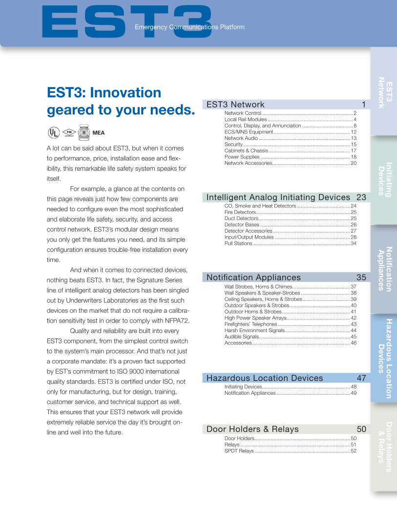


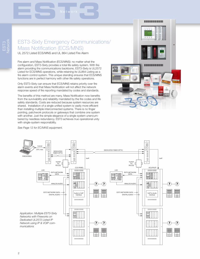
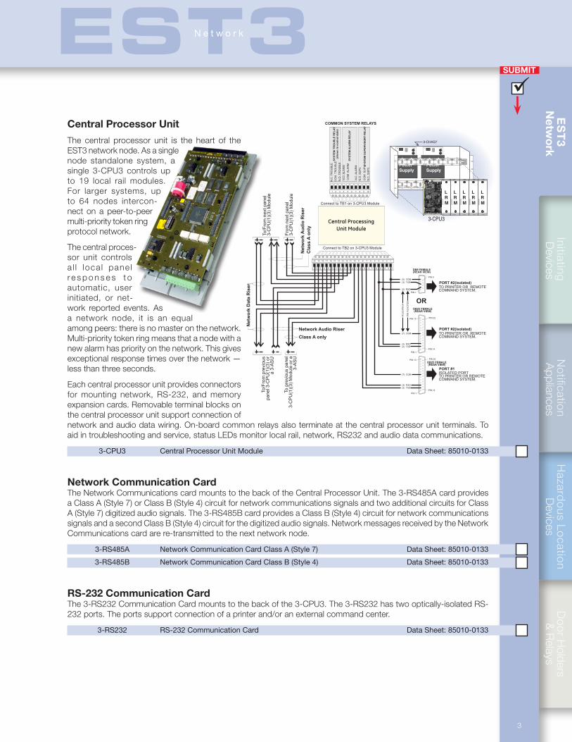

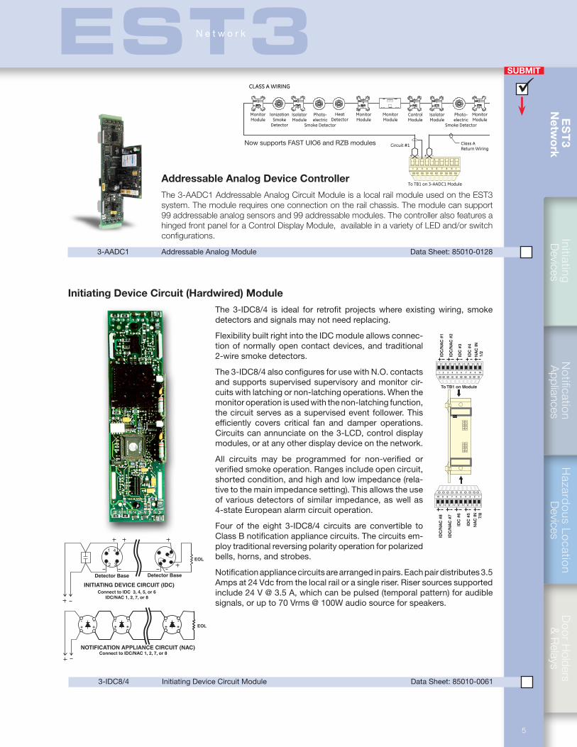
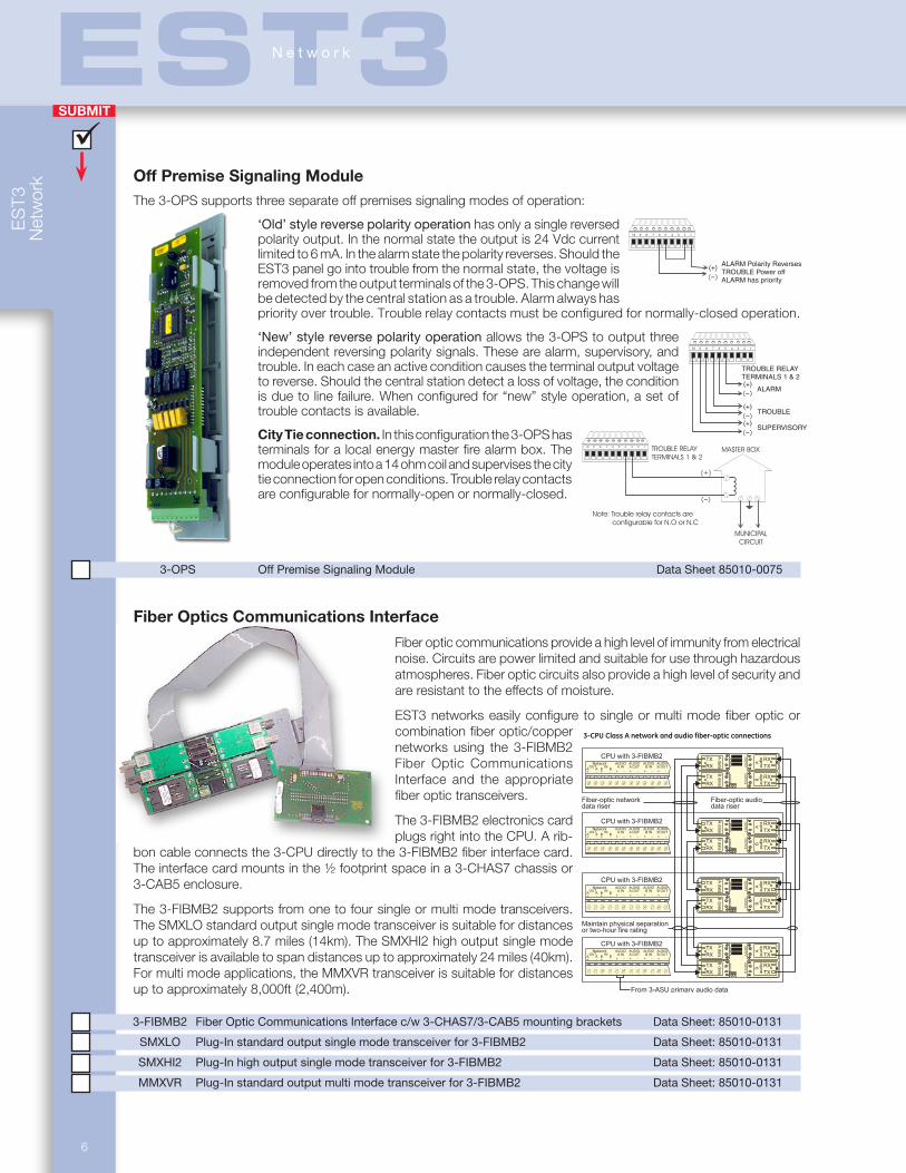
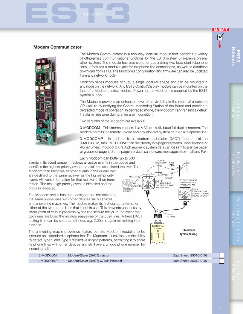
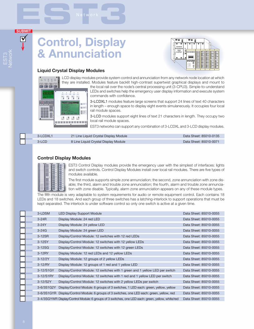

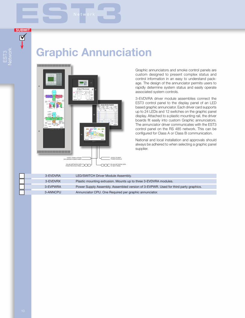


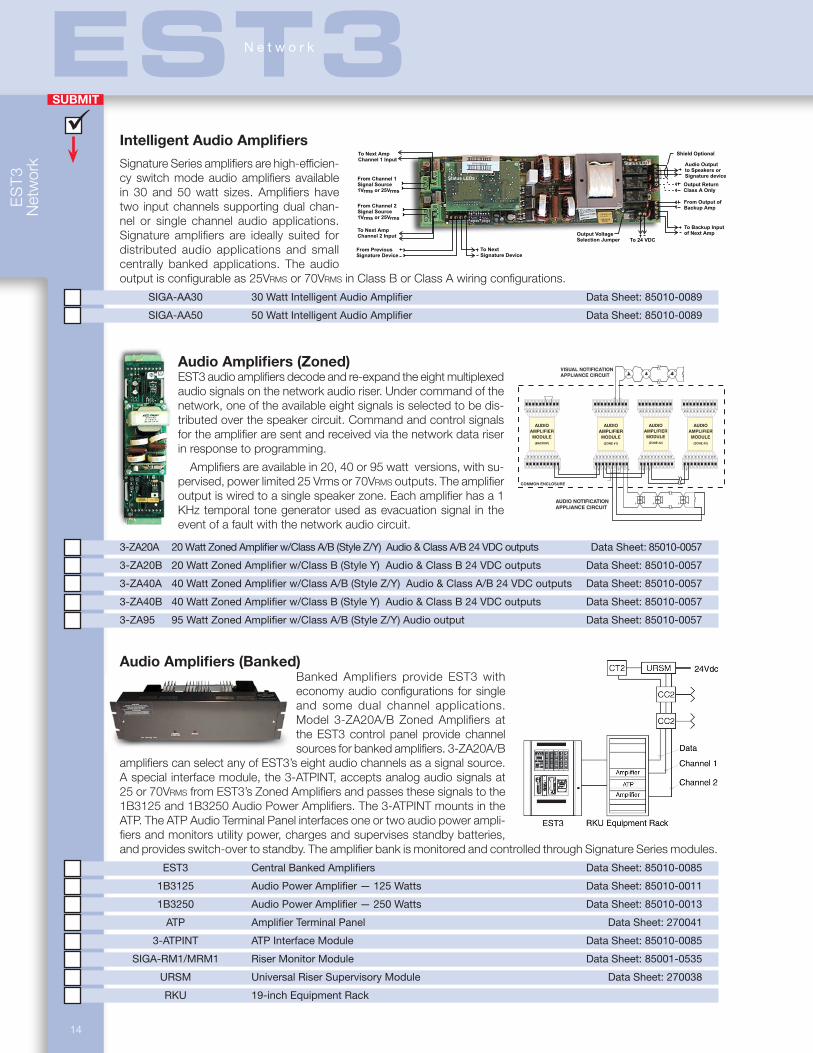


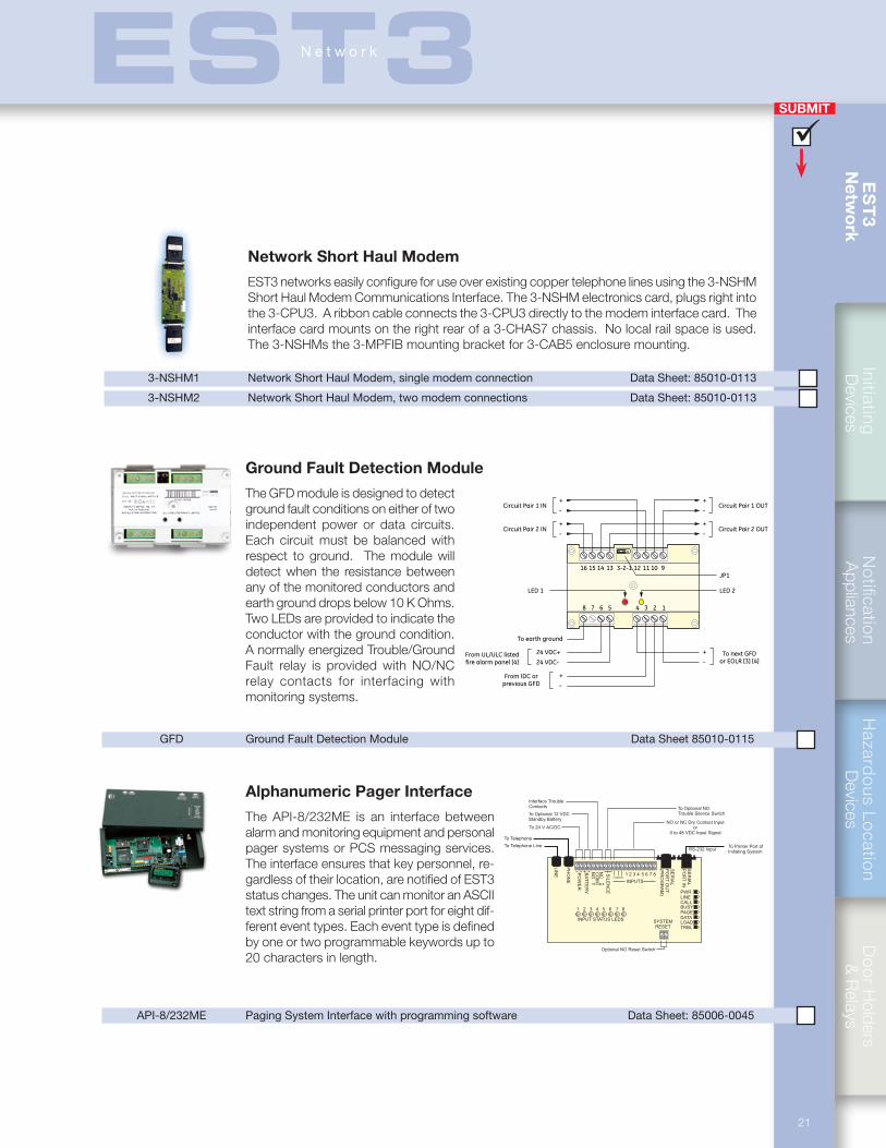

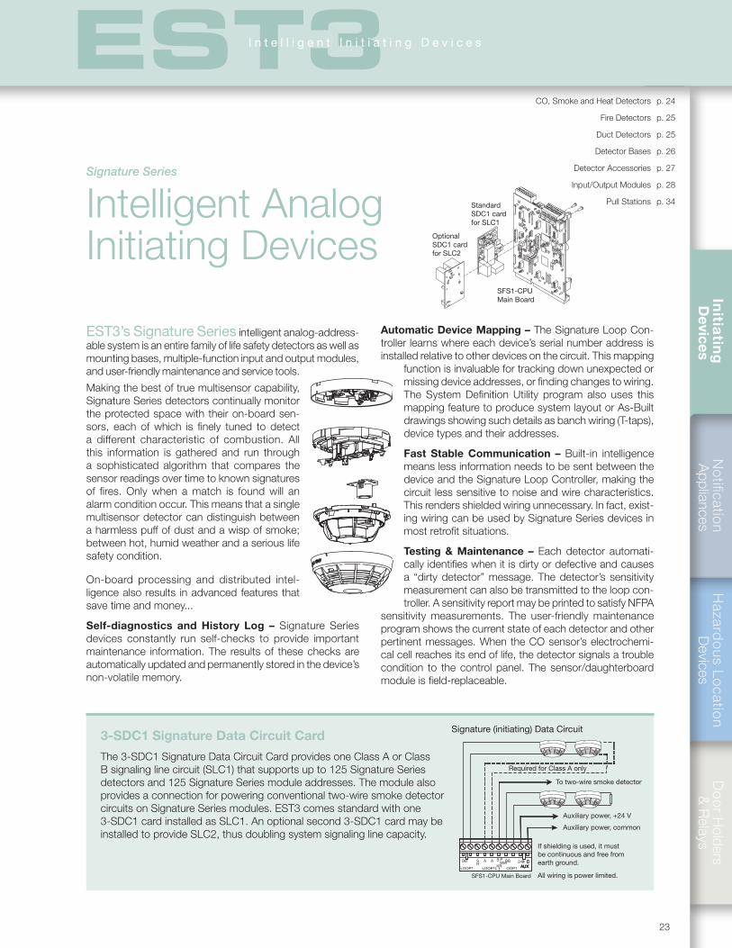


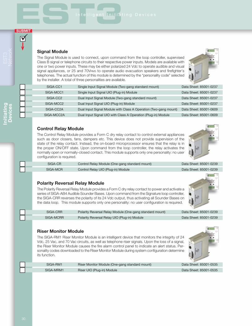

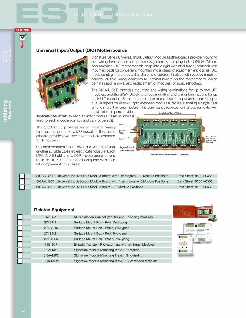


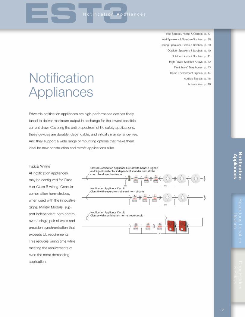

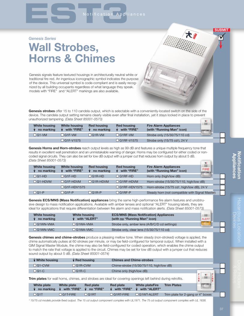
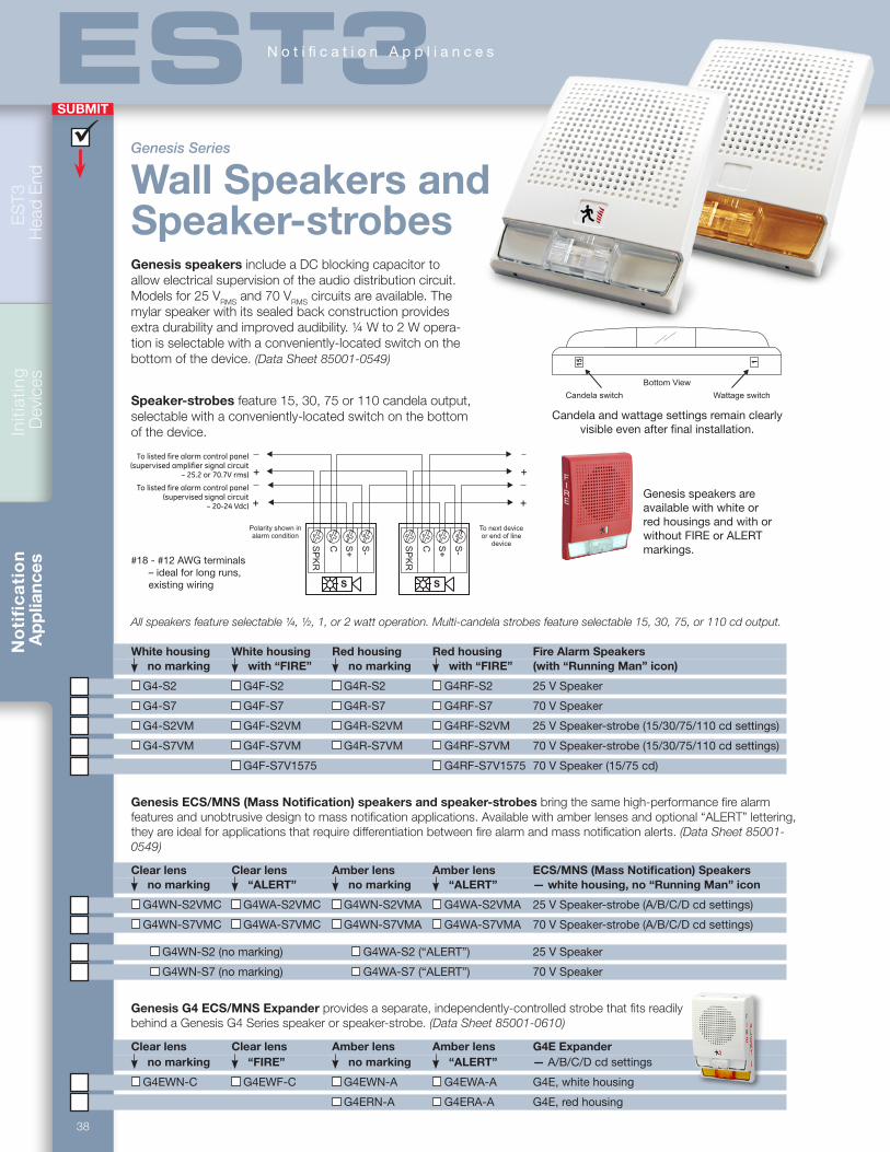

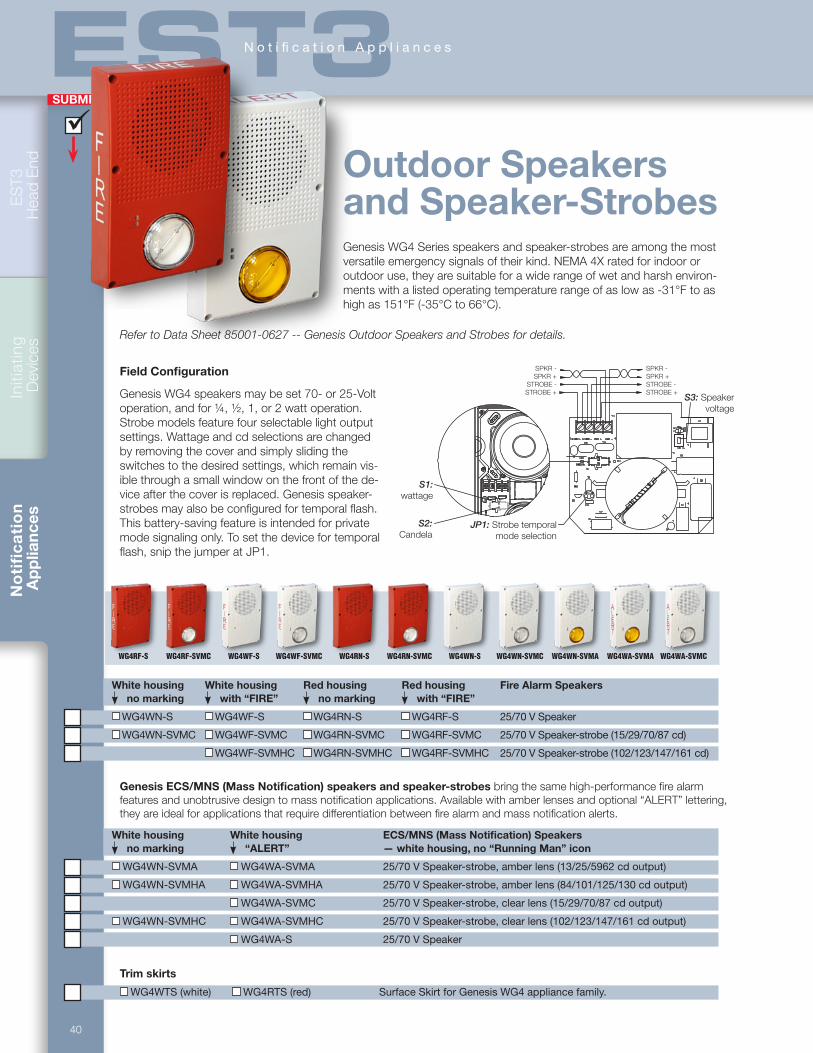


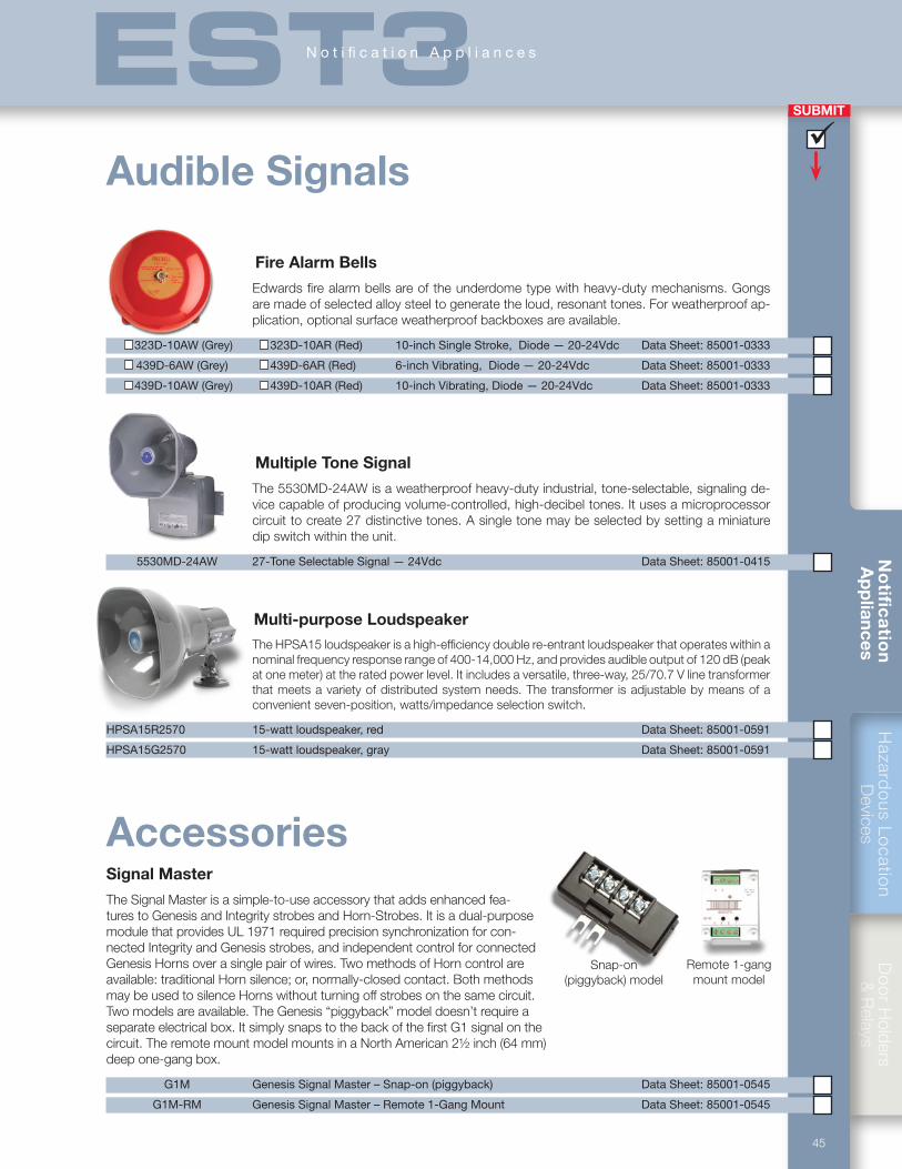


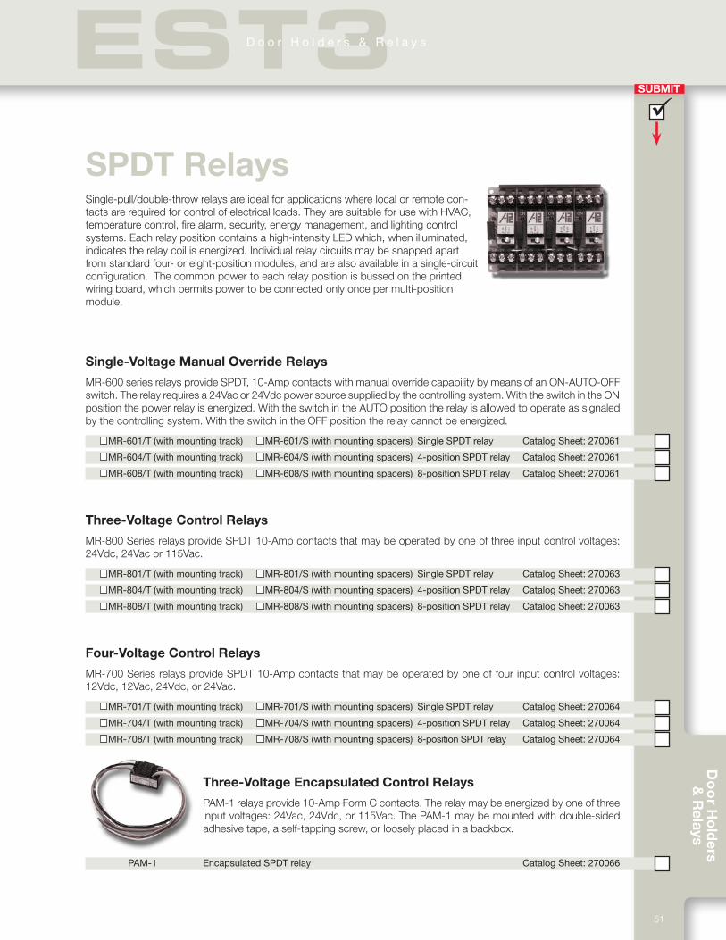


![270412 R4[1].0 EST3 SelfStudy](https://static.documents.pub/doc/80x56/5695d53d1a28ab9b02a4917b/270412-r410-est3-selfstudy.jpg)


