320
Drafting NATIONAL INSTITUTE FOR AVIATION RESEARCH Wichita State University Revision 5.14 Copyright 2005. All rights reserved. www.cadcamlab.org
Drafting
NATIONAL INSTITUTE FOR AVIATION RESEARCHWichita State University
Revision 5.14Copyright 2005. All rights reserved.
www.cadcamlab.org

None of this material may be reproduced, used or disclosed, in part or in whole, without the expressed written permission of:
National Institute for Aviation ResearchWichita State University
Wichita, KS
Copyright 2005. All rights reserved.
www.cadcamlab.org
CATIA Drafting CATIA® V5R14
Table of Contents, Page i© Wichita State University
TABLE OF CONTENTS
Introduction . . . . . . . . . . . . . . . . . . . . . . . . . . . . . . . . . . . . . . . . . . . . . . . . . . . . . . . . . . . . . . 1Drafting . . . . . . . . . . . . . . . . . . . . . . . . . . . . . . . . . . . . . . . . . . . . . . . . . . . . . . . . . . . 2Drawing Screen . . . . . . . . . . . . . . . . . . . . . . . . . . . . . . . . . . . . . . . . . . . . . . . . . . . . . 3Pull-down Menus . . . . . . . . . . . . . . . . . . . . . . . . . . . . . . . . . . . . . . . . . . . . . . . . . . . . 4
File . . . . . . . . . . . . . . . . . . . . . . . . . . . . . . . . . . . . . . . . . . . . . . . . . . . . . . . . . 4Edit . . . . . . . . . . . . . . . . . . . . . . . . . . . . . . . . . . . . . . . . . . . . . . . . . . . . . . . . . 5View . . . . . . . . . . . . . . . . . . . . . . . . . . . . . . . . . . . . . . . . . . . . . . . . . . . . . . . . 6Insert . . . . . . . . . . . . . . . . . . . . . . . . . . . . . . . . . . . . . . . . . . . . . . . . . . . . . . . . 7Tools . . . . . . . . . . . . . . . . . . . . . . . . . . . . . . . . . . . . . . . . . . . . . . . . . . . . . . . 8
Drafting Workbench . . . . . . . . . . . . . . . . . . . . . . . . . . . . . . . . . . . . . . . . . . . . . . . . . 9Views and Sheets . . . . . . . . . . . . . . . . . . . . . . . . . . . . . . . . . . . . . . . . . . . . . . 9Dimensions and Annotations . . . . . . . . . . . . . . . . . . . . . . . . . . . . . . . . . . . . 10Drawing tools . . . . . . . . . . . . . . . . . . . . . . . . . . . . . . . . . . . . . . . . . . . . . . . . 11Additional options . . . . . . . . . . . . . . . . . . . . . . . . . . . . . . . . . . . . . . . . . . . . 13
Bottom Toolbar Changes . . . . . . . . . . . . . . . . . . . . . . . . . . . . . . . . . . . . . . . . . . . . . 14Top Toolbar . . . . . . . . . . . . . . . . . . . . . . . . . . . . . . . . . . . . . . . . . . . . . . . . . . . . . . . 15
Text . . . . . . . . . . . . . . . . . . . . . . . . . . . . . . . . . . . . . . . . . . . . . . . . . . . . . . . 15Dimension . . . . . . . . . . . . . . . . . . . . . . . . . . . . . . . . . . . . . . . . . . . . . . . . . . 16Graphic properties . . . . . . . . . . . . . . . . . . . . . . . . . . . . . . . . . . . . . . . . . . . . 16
Drafting Basics . . . . . . . . . . . . . . . . . . . . . . . . . . . . . . . . . . . . . . . . . . . . . . . . . . . . . . . . . . . 17Starting a New Drawing . . . . . . . . . . . . . . . . . . . . . . . . . . . . . . . . . . . . . . . . . . . . . . 17
Creating Views from a Part . . . . . . . . . . . . . . . . . . . . . . . . . . . . . . . . . . . . . . . . . . . . . . . . . 23Front View . . . . . . . . . . . . . . . . . . . . . . . . . . . . . . . . . . . . . . . . . . . . . . . . . . . . . . . . 24Orientation Circle . . . . . . . . . . . . . . . . . . . . . . . . . . . . . . . . . . . . . . . . . . . . . . . . . . . 25Projection View . . . . . . . . . . . . . . . . . . . . . . . . . . . . . . . . . . . . . . . . . . . . . . . . . . . . 31Isometric View . . . . . . . . . . . . . . . . . . . . . . . . . . . . . . . . . . . . . . . . . . . . . . . . . . . . . 34Advanced Front View . . . . . . . . . . . . . . . . . . . . . . . . . . . . . . . . . . . . . . . . . . . . . . . 35Local Axis System . . . . . . . . . . . . . . . . . . . . . . . . . . . . . . . . . . . . . . . . . . . . . . . . . . 37Unfolded View . . . . . . . . . . . . . . . . . . . . . . . . . . . . . . . . . . . . . . . . . . . . . . . . . . . . . 38Extracted View from 3D . . . . . . . . . . . . . . . . . . . . . . . . . . . . . . . . . . . . . . . . . . . . . 40Auxiliary View . . . . . . . . . . . . . . . . . . . . . . . . . . . . . . . . . . . . . . . . . . . . . . . . . . . . . 41Section Views and Section Cuts . . . . . . . . . . . . . . . . . . . . . . . . . . . . . . . . . . . . . . . 43Detail Views . . . . . . . . . . . . . . . . . . . . . . . . . . . . . . . . . . . . . . . . . . . . . . . . . . . . . . . 49Clipping Views . . . . . . . . . . . . . . . . . . . . . . . . . . . . . . . . . . . . . . . . . . . . . . . . . . . . 54Broken View . . . . . . . . . . . . . . . . . . . . . . . . . . . . . . . . . . . . . . . . . . . . . . . . . . . . . . 55Breakout View . . . . . . . . . . . . . . . . . . . . . . . . . . . . . . . . . . . . . . . . . . . . . . . . . . . . . 57Configuration of Views . . . . . . . . . . . . . . . . . . . . . . . . . . . . . . . . . . . . . . . . . . . . . . 60Review . . . . . . . . . . . . . . . . . . . . . . . . . . . . . . . . . . . . . . . . . . . . . . . . . . . . . . . . . . . 67
Modifying Sheets . . . . . . . . . . . . . . . . . . . . . . . . . . . . . . . . . . . . . . . . . . . . . . . . . . . . . . . . . 72Sheet Properties . . . . . . . . . . . . . . . . . . . . . . . . . . . . . . . . . . . . . . . . . . . . . . . . . . . . 72Page Setup . . . . . . . . . . . . . . . . . . . . . . . . . . . . . . . . . . . . . . . . . . . . . . . . . . . . . . . . 73

CATIA Drafting CATIA® V5R14
Table of Contents, Page ii ©Wichita State University
Modifying Views . . . . . . . . . . . . . . . . . . . . . . . . . . . . . . . . . . . . . . . . . . . . . . . . . . . . . . . . . 74View Properties . . . . . . . . . . . . . . . . . . . . . . . . . . . . . . . . . . . . . . . . . . . . . . . . . . . . 74View positioning . . . . . . . . . . . . . . . . . . . . . . . . . . . . . . . . . . . . . . . . . . . . . . . . . . . 77Locating Views . . . . . . . . . . . . . . . . . . . . . . . . . . . . . . . . . . . . . . . . . . . . . . . . . . . . 80View Names . . . . . . . . . . . . . . . . . . . . . . . . . . . . . . . . . . . . . . . . . . . . . . . . . . . . . . . 80Restore Deleted . . . . . . . . . . . . . . . . . . . . . . . . . . . . . . . . . . . . . . . . . . . . . . . . . . . . 81Updating Views . . . . . . . . . . . . . . . . . . . . . . . . . . . . . . . . . . . . . . . . . . . . . . . . . . . . 82Show/NoShow . . . . . . . . . . . . . . . . . . . . . . . . . . . . . . . . . . . . . . . . . . . . . . . . . . . . . 84Callout properties . . . . . . . . . . . . . . . . . . . . . . . . . . . . . . . . . . . . . . . . . . . . . . . . . . . 85Callout Definition . . . . . . . . . . . . . . . . . . . . . . . . . . . . . . . . . . . . . . . . . . . . . . . . . . 87Unbreak and Unclip . . . . . . . . . . . . . . . . . . . . . . . . . . . . . . . . . . . . . . . . . . . . . . . . . 89Modifying Projection Plane . . . . . . . . . . . . . . . . . . . . . . . . . . . . . . . . . . . . . . . . . . . 90
Dimensioning . . . . . . . . . . . . . . . . . . . . . . . . . . . . . . . . . . . . . . . . . . . . . . . . . . . . . . . . . . . . 93Creating Dimensions . . . . . . . . . . . . . . . . . . . . . . . . . . . . . . . . . . . . . . . . . . . . . . . . 93
Length/distance . . . . . . . . . . . . . . . . . . . . . . . . . . . . . . . . . . . . . . . . . . . . . . 93Angle . . . . . . . . . . . . . . . . . . . . . . . . . . . . . . . . . . . . . . . . . . . . . . . . . . . . . 101Radius . . . . . . . . . . . . . . . . . . . . . . . . . . . . . . . . . . . . . . . . . . . . . . . . . . . . 102Diameter . . . . . . . . . . . . . . . . . . . . . . . . . . . . . . . . . . . . . . . . . . . . . . . . . . . 103General dimension . . . . . . . . . . . . . . . . . . . . . . . . . . . . . . . . . . . . . . . . . . . 104Dimensions with Intersection points . . . . . . . . . . . . . . . . . . . . . . . . . . . . . 107Chamfer . . . . . . . . . . . . . . . . . . . . . . . . . . . . . . . . . . . . . . . . . . . . . . . . . . . 108Thread . . . . . . . . . . . . . . . . . . . . . . . . . . . . . . . . . . . . . . . . . . . . . . . . . . . . 110Coordinate . . . . . . . . . . . . . . . . . . . . . . . . . . . . . . . . . . . . . . . . . . . . . . . . . 111Hole dimension table . . . . . . . . . . . . . . . . . . . . . . . . . . . . . . . . . . . . . . . . . 112Coordinate dimension table . . . . . . . . . . . . . . . . . . . . . . . . . . . . . . . . . . . . 115Chained . . . . . . . . . . . . . . . . . . . . . . . . . . . . . . . . . . . . . . . . . . . . . . . . . . . 117Cumulated . . . . . . . . . . . . . . . . . . . . . . . . . . . . . . . . . . . . . . . . . . . . . . . . . 118Stacked . . . . . . . . . . . . . . . . . . . . . . . . . . . . . . . . . . . . . . . . . . . . . . . . . . . . 119Fillet Radius Dimensions . . . . . . . . . . . . . . . . . . . . . . . . . . . . . . . . . . . . . . 120Dimensions for curves . . . . . . . . . . . . . . . . . . . . . . . . . . . . . . . . . . . . . . . . 121Setup Parameters . . . . . . . . . . . . . . . . . . . . . . . . . . . . . . . . . . . . . . . . . . . . 126Geometrical Dimensioning and Tolerancing . . . . . . . . . . . . . . . . . . . . . . . 133
Modifying Dimensions . . . . . . . . . . . . . . . . . . . . . . . . . . . . . . . . . . . . . . . . . . . . . 141Top Toolbar . . . . . . . . . . . . . . . . . . . . . . . . . . . . . . . . . . . . . . . . . . . . . . . . 141Pull Down Menu Tools, Options . . . . . . . . . . . . . . . . . . . . . . . . . . . . . . . . 142Geometrical Tolerance . . . . . . . . . . . . . . . . . . . . . . . . . . . . . . . . . . . . . . . . 144Properties . . . . . . . . . . . . . . . . . . . . . . . . . . . . . . . . . . . . . . . . . . . . . . . . . . 145Analysis . . . . . . . . . . . . . . . . . . . . . . . . . . . . . . . . . . . . . . . . . . . . . . . . . . . 160Positioning . . . . . . . . . . . . . . . . . . . . . . . . . . . . . . . . . . . . . . . . . . . . . . . . . 162Interruptions . . . . . . . . . . . . . . . . . . . . . . . . . . . . . . . . . . . . . . . . . . . . . . . . 165Update . . . . . . . . . . . . . . . . . . . . . . . . . . . . . . . . . . . . . . . . . . . . . . . . . . . . 167
Generating Dimensions . . . . . . . . . . . . . . . . . . . . . . . . . . . . . . . . . . . . . . . . . . . . . 169

CATIA Drafting CATIA® V5R14
Table of Contents, Page iii© Wichita State University
Annotations . . . . . . . . . . . . . . . . . . . . . . . . . . . . . . . . . . . . . . . . . . . . . . . . . . . . . . . . . . . . 183Creating Text . . . . . . . . . . . . . . . . . . . . . . . . . . . . . . . . . . . . . . . . . . . . . . . . . . . . . 183Modifying Text . . . . . . . . . . . . . . . . . . . . . . . . . . . . . . . . . . . . . . . . . . . . . . . . . . . 187
Top Toolbar . . . . . . . . . . . . . . . . . . . . . . . . . . . . . . . . . . . . . . . . . . . . . . . . 187Adding a Leader . . . . . . . . . . . . . . . . . . . . . . . . . . . . . . . . . . . . . . . . . . . . . 201Orientation Link . . . . . . . . . . . . . . . . . . . . . . . . . . . . . . . . . . . . . . . . . . . . . 206Positional Link . . . . . . . . . . . . . . . . . . . . . . . . . . . . . . . . . . . . . . . . . . . . . . 207Attribute link . . . . . . . . . . . . . . . . . . . . . . . . . . . . . . . . . . . . . . . . . . . . . . . 208Replicate Text . . . . . . . . . . . . . . . . . . . . . . . . . . . . . . . . . . . . . . . . . . . . . . 209Query Object Links . . . . . . . . . . . . . . . . . . . . . . . . . . . . . . . . . . . . . . . . . . 210Isolate Text . . . . . . . . . . . . . . . . . . . . . . . . . . . . . . . . . . . . . . . . . . . . . . . . . 211Element Positioning . . . . . . . . . . . . . . . . . . . . . . . . . . . . . . . . . . . . . . . . . . 212
Tables . . . . . . . . . . . . . . . . . . . . . . . . . . . . . . . . . . . . . . . . . . . . . . . . . . . . . . . . . . . 213Creating Symbols . . . . . . . . . . . . . . . . . . . . . . . . . . . . . . . . . . . . . . . . . . . . . . . . . . 221
Balloon . . . . . . . . . . . . . . . . . . . . . . . . . . . . . . . . . . . . . . . . . . . . . . . . . . . . 221Roughness Symbol . . . . . . . . . . . . . . . . . . . . . . . . . . . . . . . . . . . . . . . . . . . 223Welding Symbol . . . . . . . . . . . . . . . . . . . . . . . . . . . . . . . . . . . . . . . . . . . . 225Weld . . . . . . . . . . . . . . . . . . . . . . . . . . . . . . . . . . . . . . . . . . . . . . . . . . . . . . 227
Markup . . . . . . . . . . . . . . . . . . . . . . . . . . . . . . . . . . . . . . . . . . . . . . . . . . . . . . . . . . . . . . . . 228Center lines and Axis lines . . . . . . . . . . . . . . . . . . . . . . . . . . . . . . . . . . . . . . . . . . 228Area Fill . . . . . . . . . . . . . . . . . . . . . . . . . . . . . . . . . . . . . . . . . . . . . . . . . . . . . . . . . 231Modifying an Area Fill . . . . . . . . . . . . . . . . . . . . . . . . . . . . . . . . . . . . . . . . . . . . . . 234
Properties . . . . . . . . . . . . . . . . . . . . . . . . . . . . . . . . . . . . . . . . . . . . . . . . . . 234Top Toolbar . . . . . . . . . . . . . . . . . . . . . . . . . . . . . . . . . . . . . . . . . . . . . . . . 237
Graphical properties . . . . . . . . . . . . . . . . . . . . . . . . . . . . . . . . . . . . . . . . . . . . . . . . 239Arrows . . . . . . . . . . . . . . . . . . . . . . . . . . . . . . . . . . . . . . . . . . . . . . . . . . . . . . . . . . 240
Assembly . . . . . . . . . . . . . . . . . . . . . . . . . . . . . . . . . . . . . . . . . . . . . . . . . . . . . . . . . . . . . . 241Creating an isometric view . . . . . . . . . . . . . . . . . . . . . . . . . . . . . . . . . . . . . . . . . . 241Creating a view from a scene . . . . . . . . . . . . . . . . . . . . . . . . . . . . . . . . . . . . . . . . . 242Generate balloons . . . . . . . . . . . . . . . . . . . . . . . . . . . . . . . . . . . . . . . . . . . . . . . . . . 244Bill of Material . . . . . . . . . . . . . . . . . . . . . . . . . . . . . . . . . . . . . . . . . . . . . . . . . . . . 245Other views . . . . . . . . . . . . . . . . . . . . . . . . . . . . . . . . . . . . . . . . . . . . . . . . . . . . . . 246Properties of a part in an assembly . . . . . . . . . . . . . . . . . . . . . . . . . . . . . . . . . . . . 248Overload properties . . . . . . . . . . . . . . . . . . . . . . . . . . . . . . . . . . . . . . . . . . . . . . . . 250Cut, Copy and Paste views . . . . . . . . . . . . . . . . . . . . . . . . . . . . . . . . . . . . . . . . . . . 253Views of parts of an assembly . . . . . . . . . . . . . . . . . . . . . . . . . . . . . . . . . . . . . . . . 255View Links . . . . . . . . . . . . . . . . . . . . . . . . . . . . . . . . . . . . . . . . . . . . . . . . . . . . . . . 258
2D Geometry . . . . . . . . . . . . . . . . . . . . . . . . . . . . . . . . . . . . . . . . . . . . . . . . . . . . . . . . . . . 261Creating a view . . . . . . . . . . . . . . . . . . . . . . . . . . . . . . . . . . . . . . . . . . . . . . . . . . . 261Drawing tools . . . . . . . . . . . . . . . . . . . . . . . . . . . . . . . . . . . . . . . . . . . . . . . . . . . . . 261View plane definition . . . . . . . . . . . . . . . . . . . . . . . . . . . . . . . . . . . . . . . . . . . . . . . 265Multiple view projection . . . . . . . . . . . . . . . . . . . . . . . . . . . . . . . . . . . . . . . . . . . . 2662D Components . . . . . . . . . . . . . . . . . . . . . . . . . . . . . . . . . . . . . . . . . . . . . . . . . . . 269Background . . . . . . . . . . . . . . . . . . . . . . . . . . . . . . . . . . . . . . . . . . . . . . . . . . . . . . 274
CATIA Drafting CATIA® V5R14
Table of Contents, Page iv ©Wichita State University
Review . . . . . . . . . . . . . . . . . . . . . . . . . . . . . . . . . . . . . . . . . . . . . . . . . . . . . . . . . . . . . . . . 281Geometry in all viewpoints . . . . . . . . . . . . . . . . . . . . . . . . . . . . . . . . . . . . . . . . . . 286Filter generated elements . . . . . . . . . . . . . . . . . . . . . . . . . . . . . . . . . . . . . . . . . . . . 286Exporting . . . . . . . . . . . . . . . . . . . . . . . . . . . . . . . . . . . . . . . . . . . . . . . . . . . . . . . . 286
Problems . . . . . . . . . . . . . . . . . . . . . . . . . . . . . . . . . . . . . . . . . . . . . . . . . . . . . . . . . . . . . . 287Problem #01 . . . . . . . . . . . . . . . . . . . . . . . . . . . . . . . . . . . . . . . . . . . . . . . . . . . . . . 287Problem #02 . . . . . . . . . . . . . . . . . . . . . . . . . . . . . . . . . . . . . . . . . . . . . . . . . . . . . . 288Problem #03 . . . . . . . . . . . . . . . . . . . . . . . . . . . . . . . . . . . . . . . . . . . . . . . . . . . . . . 289Problem #04 . . . . . . . . . . . . . . . . . . . . . . . . . . . . . . . . . . . . . . . . . . . . . . . . . . . . . . 290Problem #05 . . . . . . . . . . . . . . . . . . . . . . . . . . . . . . . . . . . . . . . . . . . . . . . . . . . . . . 291Problem #06 . . . . . . . . . . . . . . . . . . . . . . . . . . . . . . . . . . . . . . . . . . . . . . . . . . . . . . 292Problem #07 . . . . . . . . . . . . . . . . . . . . . . . . . . . . . . . . . . . . . . . . . . . . . . . . . . . . . . 293Problem #08 . . . . . . . . . . . . . . . . . . . . . . . . . . . . . . . . . . . . . . . . . . . . . . . . . . . . . . 294Problem #09 . . . . . . . . . . . . . . . . . . . . . . . . . . . . . . . . . . . . . . . . . . . . . . . . . . . . . . 295Problem #10 . . . . . . . . . . . . . . . . . . . . . . . . . . . . . . . . . . . . . . . . . . . . . . . . . . . . . . 296Problem #11 . . . . . . . . . . . . . . . . . . . . . . . . . . . . . . . . . . . . . . . . . . . . . . . . . . . . . . 297Problem #12 . . . . . . . . . . . . . . . . . . . . . . . . . . . . . . . . . . . . . . . . . . . . . . . . . . . . . . 298Problem #13 . . . . . . . . . . . . . . . . . . . . . . . . . . . . . . . . . . . . . . . . . . . . . . . . . . . . . . 299Problem #14 . . . . . . . . . . . . . . . . . . . . . . . . . . . . . . . . . . . . . . . . . . . . . . . . . . . . . . 300Problem #15 . . . . . . . . . . . . . . . . . . . . . . . . . . . . . . . . . . . . . . . . . . . . . . . . . . . . . . 301
Appendix A . . . . . . . . . . . . . . . . . . . . . . . . . . . . . . . . . . . . . . . . . . . . . . . . . . . . . . . . . . . . 303Mechanical Design - Drafting - General . . . . . . . . . . . . . . . . . . . . . . . . . . . . . . . . 303Mechanical Design - Drafting - Layout . . . . . . . . . . . . . . . . . . . . . . . . . . . . . . . . . 304Mechanical Design - Drafting - View . . . . . . . . . . . . . . . . . . . . . . . . . . . . . . . . . . 305Mechanical Design - Drafting - Generation . . . . . . . . . . . . . . . . . . . . . . . . . . . . . . 306Mechanical Design - Drafting - Geometry . . . . . . . . . . . . . . . . . . . . . . . . . . . . . . . 307Mechanical Design - Drafting - Dimension . . . . . . . . . . . . . . . . . . . . . . . . . . . . . . 308Mechanical Design - Drafting - Manipulators . . . . . . . . . . . . . . . . . . . . . . . . . . . . 310Mechanical Design - Drafting - Annotation and Dress-Up . . . . . . . . . . . . . . . . . . 311Mechanical Design - Drafting - Administration . . . . . . . . . . . . . . . . . . . . . . . . . . 312

CATIA Drafting CATIA® V5R14
Introduction, Page 1© Wichita State University
Introduction
CATIA Version 5 Drafting
Upon completion of this course the student should have a full understanding of thefollowing topics:
- Creating drawings
- Creating views
- Modifying views
- Creating detail, broken, auxiliary and section cut views
- Dimensioning and marking up view geometry
- Creating text
- Using symbols, details and patterns in a drawing
- Creating and modifying basic geometry
- Using folding lines and multi-view projections to create view geometry
- Creating and using backgrounds
CATIA Drafting CATIA® V5R14
Introduction, Page 2 ©Wichita State University
Drafting
Currently, it is necessary for designers to create paper drawings and layouts of their partsand assemblies. This course will cover the steps necessary to create multiple view drawingsand detail sheets of parts and assemblies. This will include all annotations and dimensionsthat are necessary to finish a completed drawing.
The drafting workbench includes a variety of icons that allow for the creation of thesedrawings. It is normally considered that the workflow should be from 3D to 2D. There aresome tools for generating 2D geometry independent of a 3D model but it is not a commonoccurrence in most cases.
You should already have a good understanding of Part Design upon starting this course.This will complete a basic cycle of events from designing your own parts and creating amultiple view drawing. The course will also show how you can create a multiple sheetdrawing of an assembly as well as the detail drawings of the individual parts. Unfortunatelythe industry still requires and depends heavily on paper drawings. There has been muchdiscussion on “paper-less” environments where the end users would just pull up the designon the computer and analyze the areas of interest. In the future that may be the case butuntil then this is an extremely important aspect of your V5 knowledge.
At any point it will be necessary to create drawings for technical publications andhandbooks. This class will also explore the options available to export pictures fromCATIA to wordprocessors that then could be used to create technical documents or evenweb documents.
CATIA Drafting CATIA® V5R14
Introduction, Page 3© Wichita State University
Drawing Screen
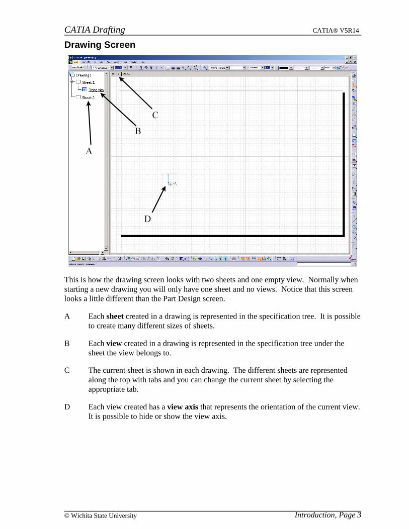
This is how the drawing screen looks with two sheets and one empty view. Normally whenstarting a new drawing you will only have one sheet and no views. Notice that this screenlooks a little different than the Part Design screen.
A Each sheet created in a drawing is represented in the specification tree. It is possibleto create many different sizes of sheets.
B Each view created in a drawing is represented in the specification tree under thesheet the view belongs to.
C The current sheet is shown in each drawing. The different sheets are representedalong the top with tabs and you can change the current sheet by selecting theappropriate tab.
D Each view created has a view axis that represents the orientation of the current view.It is possible to hide or show the view axis.

CATIA Drafting CATIA® V5R14
Introduction, Page 4 ©Wichita State University
Pull-down Menus
File
Page Setup You can change the Standardthat you want to use and basedon that standard you can changethe Sheet Style. You can alsoinsert a background view andapply this to just the currentsheet or to all of the sheets.
CATIA Drafting CATIA® V5R14
Introduction, Page 5© Wichita State University
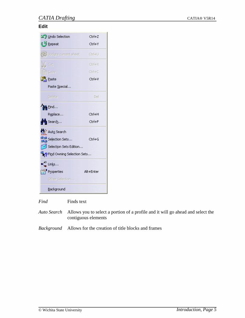
Edit
Find Finds text
Auto Search Allows you to select a portion of a profile and it will go ahead and select thecontiguous elements
Background Allows for the creation of title blocks and frames

CATIA Drafting CATIA® V5R14
Introduction, Page 6 ©Wichita State University
View
Drawing Overview Gives an overview window of the drawing, allowing you to zoom inon an area of the geometry

CATIA Drafting CATIA® V5R14
Introduction, Page 7© Wichita State University
Insert
Views Inserts various types of views
Drawing Inserts drawing elements such as sheets
Dimensioning Creates dimensions
Generation Generates dimensions from constraints
Annotations Creates annotations
Dress Up Inserts additional features such as thread notation, arrows andarea fills
Geometry creation Creates geometric elements
Geometry modification Modifies geometric elements
Picture Inserts a picture (jpeg, tiff, bmp, etc.)

CATIA Drafting CATIA® V5R14
Introduction, Page 8 ©Wichita State University
Tools
Positioning Positions elements and dimensions
Analyze Analyzes your dimensions
Multi View (2.5 D) Used to project geometry to differentviews
Dimension generation Analysis and filters for generatingdimensions from constraints
Import a generative view style Imports a view style
Reset All Defaults Resets the defaults
Import External Format Allows you to import an external file such as a dwg,dxf or cgm
CATIA Drafting CATIA® V5R14
Introduction, Page 9© Wichita State University
Drafting Workbench
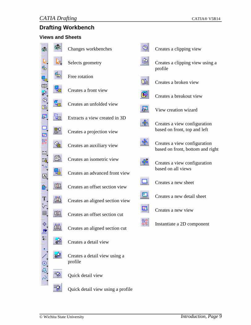
Views and Sheets
Changes workbenches
Selects geometry
Free rotation
Creates a front view
Creates an unfolded view
Extracts a view created in 3D
Creates a projection view
Creates an auxiliary view
Creates an isometric view
Creates an advanced front view
Creates an offset section view
Creates an aligned section view
Creates an offset section cut
Creates an aligned section cut
Creates a detail view
Creates a detail view using aprofile
Quick detail view
Quick detail view using a profile
Creates a clipping view
Creates a clipping view using aprofile
Creates a broken view
Creates a breakout view
View creation wizard
Creates a view configurationbased on front, top and left
Creates a view configurationbased on front, bottom and right
Creates a view configurationbased on all views
Creates a new sheet
Creates a new detail sheet
Creates a new view
Instantiate a 2D component
CATIA Drafting CATIA® V5R14
Introduction, Page 10 ©Wichita State University
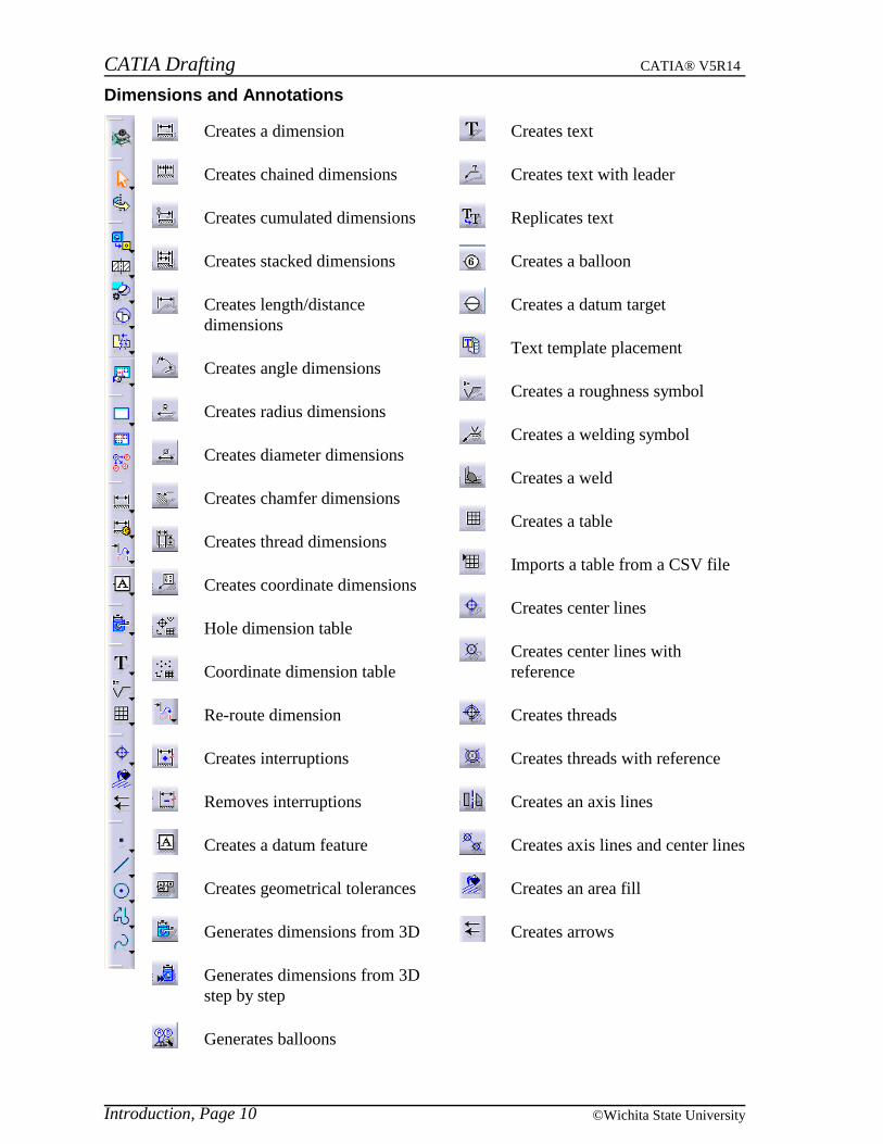
Dimensions and Annotations
Creates a dimension
Creates chained dimensions
Creates cumulated dimensions
Creates stacked dimensions
Creates length/distancedimensions
Creates angle dimensions
Creates radius dimensions
Creates diameter dimensions
Creates chamfer dimensions
Creates thread dimensions
Creates coordinate dimensions
Hole dimension table
Coordinate dimension table
Re-route dimension
Creates interruptions
Removes interruptions
Creates a datum feature
Creates geometrical tolerances
Generates dimensions from 3D
Generates dimensions from 3Dstep by step
Generates balloons
Creates text
Creates text with leader
Replicates text
Creates a balloon
Creates a datum target
Text template placement
Creates a roughness symbol
Creates a welding symbol
Creates a weld
Creates a table
Imports a table from a CSV file
Creates center lines
Creates center lines withreference
Creates threads
Creates threads with reference
Creates an axis lines
Creates axis lines and center lines
Creates an area fill
Creates arrows

CATIA Drafting CATIA® V5R14
Introduction, Page 11© Wichita State University
Drawing tools
Creates a point
Creates a point using coordinates
Creates equidistant points
Creates an intersection point
Creates a projected point
Creates a line
Creates an unlimited line
Creates a bitangent line
Creates a bisect line
Creates a line normal to a curve
Creates a circle
Creates a circle through 3 points
Creates a circle using coordinates
Creates a circle tangent to 3elements
Creates an arc
Creates an arc through 3 points
Creates an arc through 3 pointsusing limits
Creates an ellipse
Creates a user-defined profile
Creates a rectangle
Creates an oriented rectangle
Creates a parallelogram
Creates a hexagon
Creates an elongated slot
Creates an elongated curved slot
Creates a keyhole
Creates a centered rectangle
Creates a centered parallelogram
Creates a spline
Creates a connect curve
Creates a parabola
Creates a hyperbola
Creates a conic
Creates rounded corners
Chamfers elements
Trims elements
Breaks elements
Quick trim
Closes elements
Generates the complement of anelement
CATIA Drafting CATIA® V5R14
Introduction, Page 12 ©Wichita State University
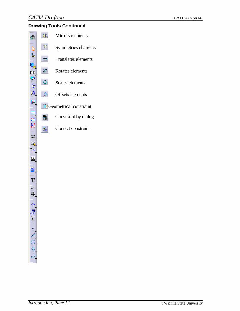
Drawing Tools Continued
Mirrors elements
Symmetries elements
Translates elements
Rotates elements
Scales elements
Offsets elements
Geometrical constraint
Constraint by dialog
Contact constraint

CATIA Drafting CATIA® V5R14
Introduction, Page 13© Wichita State University
Additional options
These options are available if you add these toolbars using the pull down menu View,Toolbars.
Creates projected geometry in the current view using 2 other views
Modifies the 3D definition of the view plane
Shows geometry in all viewpoints
Analyses the dimensions positioning
Positions elements such as views and annotations
Aligns dimensions between each other or relative to geometry
Aligns a system of dimensions
Positions dimensions
Positions and orients objects
CATIA Drafting CATIA® V5R14
Introduction, Page 14 ©Wichita State University
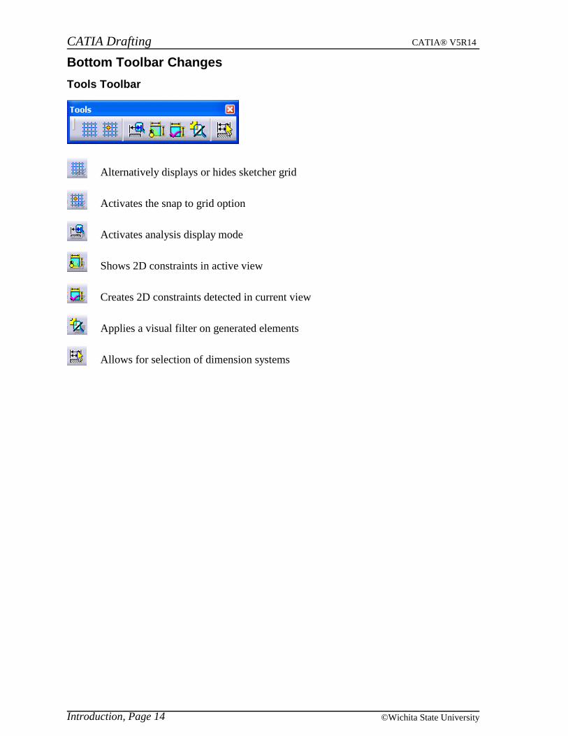
Bottom Toolbar Changes
Tools Toolbar
Alternatively displays or hides sketcher grid
Activates the snap to grid option
Activates analysis display mode
Shows 2D constraints in active view
Creates 2D constraints detected in current view
Applies a visual filter on generated elements
Allows for selection of dimension systems

CATIA Drafting CATIA® V5R14
Introduction, Page 15© Wichita State University
Top Toolbar
Changes the current style for graphic properties
Text
Changes the current font
Changes the size of the font
Toggles the bold style for text
Toggles the italics style for text
Toggles the underline style for text
Toggles the strike thru style for text
Toggles the overline style for text
Toggles the superscript style for text
Toggles the subscript style for text
Changes the paragraph style to leftjustification
Changes the paragraph style tocenter justification
Changes the paragraph style to rightjustification
Sets the anchor point position fortext
Sets up a frame around the text
Insert a symbol into some text

CATIA Drafting CATIA® V5R14
Introduction, Page 16 ©Wichita State University
Dimension
Dimension lines set to normal
Dimension lines set to be extended
Dimension lines set to use a leader with one part
Dimension lines set to use a leader with two parts
Changes the current tolerance style
Changes the tolerance
Changes the current numerical style
Changes the precision
Graphic properties
Changes the color
Changes the thickness
Changes the linetype
Changes point symbol
Changes the current layer
Copies the properties of the currently selected object
Change a pattern currently used in the drawing

CATIA Drafting CATIA® V5R14
Drafting Basics, Page 17© Wichita State University
Drafting Basics
Starting a New Drawing
This will cover the necessary steps to create and modify a CATIA Drawing. There are acouple different ways to start a CATIA Drawing. The first way is to start a model the sameway that you created a document in other classes, with pull down menu File or using theequivalent icon in the bottom toolbar. Another way is to be in a document such as a part orassembly and then change to the Drafting workbench.
The first method will be discussed now. This is useful if you want to just start a newdrawing and begin modeling in 2D.
Select the new icon in the bottom toolbar. This allows you to create a newdocument. The document that is created depends on the selection you make: either ananalysis, drawing, part, or product.
Select Drawing. This will allow you to create a new type of document called aCATDrawing.
CATIA Drafting CATIA® V5R14
Drafting Basics, Page 18 ©Wichita State University
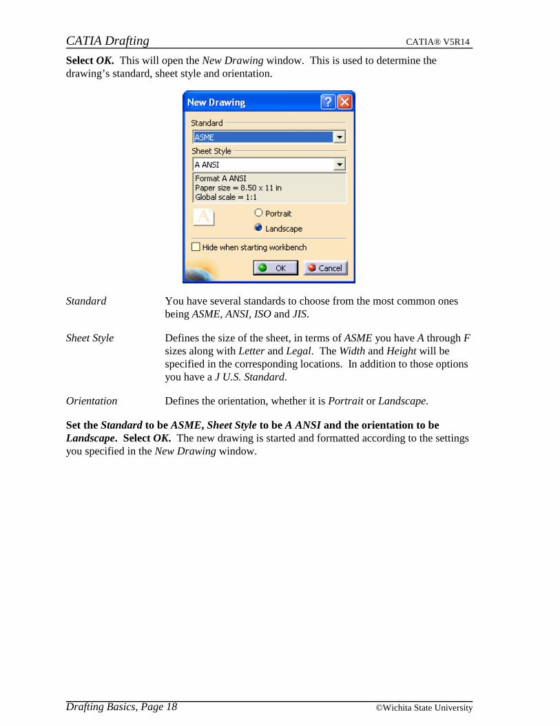
Select OK. This will open the New Drawing window. This is used to determine thedrawing’s standard, sheet style and orientation.
Standard You have several standards to choose from the most common onesbeing ASME, ANSI, ISO and JIS.
Sheet Style Defines the size of the sheet, in terms of ASME you have A through Fsizes along with Letter and Legal. The Width and Height will bespecified in the corresponding locations. In addition to those optionsyou have a J U.S. Standard.
Orientation Defines the orientation, whether it is Portrait or Landscape.
Set the Standard to be ASME, Sheet Style to be A ANSI and the orientation to beLandscape. Select OK. The new drawing is started and formatted according to the settingsyou specified in the New Drawing window.
CATIA Drafting CATIA® V5R14
Drafting Basics, Page 19© Wichita State University
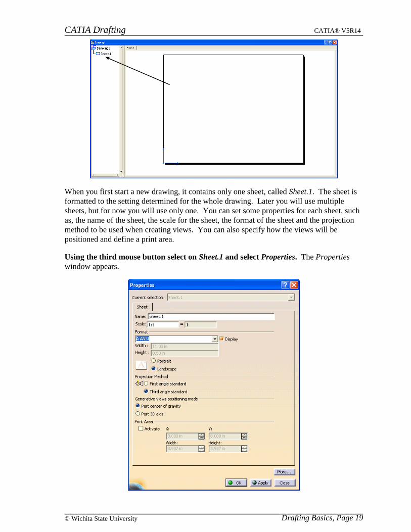
When you first start a new drawing, it contains only one sheet, called Sheet.1. The sheet isformatted to the setting determined for the whole drawing. Later you will use multiplesheets, but for now you will use only one. You can set some properties for each sheet, suchas, the name of the sheet, the scale for the sheet, the format of the sheet and the projectionmethod to be used when creating views. You can also specify how the views will bepositioned and define a print area.
Using the third mouse button select on Sheet.1 and select Properties. The Propertieswindow appears.

CATIA Drafting CATIA® V5R14
Drafting Basics, Page 20 ©Wichita State University
Change the name to be Drafting Sheet 1 but do not press Enter. The name has beenchanged to Drafting Sheet 1. You can also change the scale and the format of the sheet hereif you want, but you cannot change the standard of the sheet. You can change theProjection Method, which determines if it should use first angle or third angle projectionwhen creating views. The Generative views positioning mode changes where the axis of thedrawing will be. Print Area deals with exact area of the drawing that you wish to print.
Select OK. This closes the Properties window and returns you to the drawing.
Sometimes more than one sheet is needed to contain the entire drawing. CATIA V5 allowsyou to add sheets to the drawing and also delete them.
Select the new sheet icon. A new sheet is created and added to your drawing. Thesheet is the same size as the first sheet. You can switch between the two sheets using thetabs at the top of the drawing or by double selecting on the sheet name in the specificationtree.
The new sheet uses the same scale as the first sheet. You will now delete the sheet you justcreated.
Select Sheet.2 from the specification tree and press the Delete key on the keyboard. AConfirm Sheet Delete window appears. This lets you know that the deletion cannot beundone.
Select OK. The sheet is deleted.
Close this document. You will now create a new drawing using an alternate method.

CATIA Drafting CATIA® V5R14
Drafting Basics, Page 21© Wichita State University
Open the Pawl Hook document. Notice that this is a part that has already been created.You will now enter the Drafting workbench.
Change to the Drafting workbench. You can change workbenches by using the pull downmenu Start or by using the change workbench icon. A New Drawing Creation windowappears.
Notice that the standard, format, orientation and scale are all set to what you used last time.You can change those settings by using the Modify button and this will open the NewDrawing window that you saw earlier.
You now have the option of choosing an empty sheet, similar to what you did when youcreated a new drawing earlier, or you can choose one of the automatic layouts. The fouroptions are empty sheet; all views; front, bottom and right; or front, top and left.
Choose the empty sheet option and select OK. This will create a drawing just like beforewith one sheet that is empty. For purposes of understanding the other three layouts, picturesare shown below with the result of each one.
This is the all views option. Notice that all the views are generated and appear in thedrawing, but they do not fit on the sheet. You will learn more about views later in thiscourse.
CATIA Drafting CATIA® V5R14
Drafting Basics, Page 22 ©Wichita State University
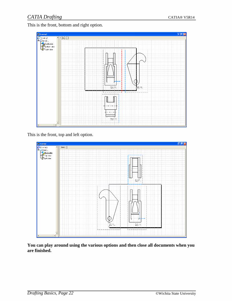
This is the front, bottom and right option.
This is the front, top and left option.
You can play around using the various options and then close all documents when youare finished.
CATIA Drafting CATIA® V5R14
Creating Views, Page 23© Wichita State University
Creating Views from a Part
There are many types of views that can be created in CATIA Drafting. This section isdesigned to cover all of the various types of views that can be created. As discussed earlieryou can create a drawing in one of two ways, you can either begin a drawing with an emptysheet or with a configuration of views. Initially you will be starting a new drawing with anempty sheet.
Before you begin, make sure that you do not have any other windows open in CATIA.
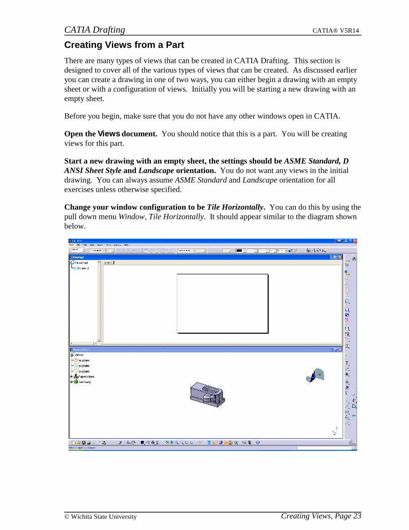
Open the Views document. You should notice that this is a part. You will be creatingviews for this part.
Start a new drawing with an empty sheet, the settings should be ASME Standard, DANSI Sheet Style and Landscape orientation. You do not want any views in the initialdrawing. You can always assume ASME Standard and Landscape orientation for allexercises unless otherwise specified.
Change your window configuration to be Tile Horizontally. You can do this by using thepull down menu Window, Tile Horizontally. It should appear similar to the diagram shownbelow.

CATIA Drafting CATIA® V5R14
Creating Views, Page 24 ©Wichita State University
Front View
The first view created is normally the front view. You can create a front view by definingthe 3D object that you want to use and defining the plane that should be used to define theview.
Select the front view icon. This will allow you to define a plane from a 3D objectand create the front view.
Select the plane shown below from the part. This will define the plane that you want touse for the front view.
The diagram shown below should appear in your drawing window.
Notice that the part appears in the drawing window and you have a blue orientation circle inthe upper right-hand corner of your window. This circle allows you to orient your viewbefore actually creating it. Once the view is oriented the way you want it then you caneither select on the center dot or select outside the blue circle to create the view. You aregoing to investigate the various options that you have available for orienting the view.
CATIA Drafting CATIA® V5R14
Creating Views, Page 25© Wichita State University
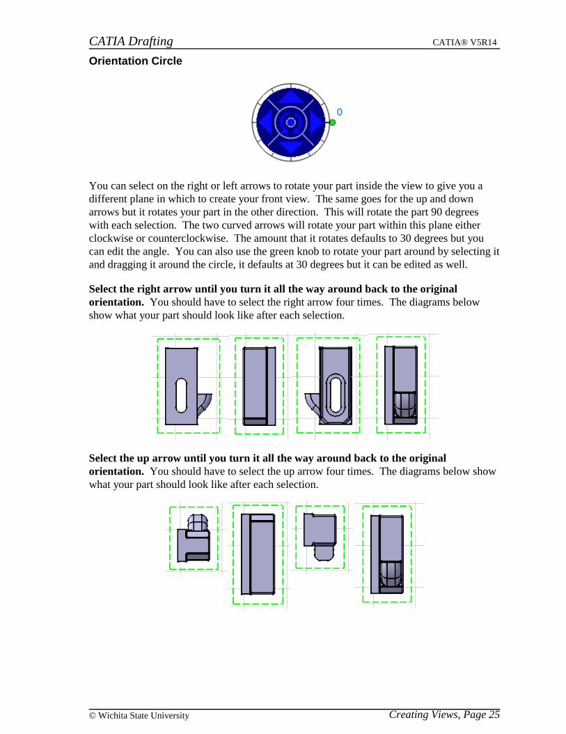
Orientation Circle
You can select on the right or left arrows to rotate your part inside the view to give you adifferent plane in which to create your front view. The same goes for the up and downarrows but it rotates your part in the other direction. This will rotate the part 90 degreeswith each selection. The two curved arrows will rotate your part within this plane eitherclockwise or counterclockwise. The amount that it rotates defaults to 30 degrees but youcan edit the angle. You can also use the green knob to rotate your part around by selecting itand dragging it around the circle, it defaults at 30 degrees but it can be edited as well.
Select the right arrow until you turn it all the way around back to the originalorientation. You should have to select the right arrow four times. The diagrams belowshow what your part should look like after each selection.
Select the up arrow until you turn it all the way around back to the originalorientation. You should have to select the up arrow four times. The diagrams below showwhat your part should look like after each selection.
CATIA Drafting CATIA® V5R14
Creating Views, Page 26 ©Wichita State University
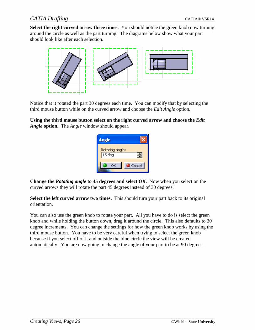
Select the right curved arrow three times. You should notice the green knob now turningaround the circle as well as the part turning. The diagrams below show what your partshould look like after each selection.
Notice that it rotated the part 30 degrees each time. You can modify that by selecting thethird mouse button while on the curved arrow and choose the Edit Angle option.
Using the third mouse button select on the right curved arrow and choose the EditAngle option. The Angle window should appear.
Change the Rotating angle to 45 degrees and select OK. Now when you select on thecurved arrows they will rotate the part 45 degrees instead of 30 degrees.
Select the left curved arrow two times. This should turn your part back to its originalorientation.
You can also use the green knob to rotate your part. All you have to do is select the greenknob and while holding the button down, drag it around the circle. This also defaults to 30degree increments. You can change the settings for how the green knob works by using thethird mouse button. You have to be very careful when trying to select the green knobbecause if you select off of it and outside the blue circle the view will be createdautomatically. You are now going to change the angle of your part to be at 90 degrees.

CATIA Drafting CATIA® V5R14
Creating Views, Page 27© Wichita State University
Using the third mouse button select on the green knob. Make sure you are on the greenknob when you press the button. This will give you the following options.
Free hand rotation Allows you to rotate the part at any angle
Incremental hand rotation Allows you to rotate the part at a given increment
Set increment Sets the amount of the increment for Incremental handrotation
Set current angle to Allows you to specify an angle that you want to rotate the part
Select the Set current angle to option and choose 90 deg from the menu. This rotatesyour part to be at 90 degrees. You are now ready to create the actual view since you have itoriented the way you want.
CATIA Drafting CATIA® V5R14
Creating Views, Page 28 ©Wichita State University
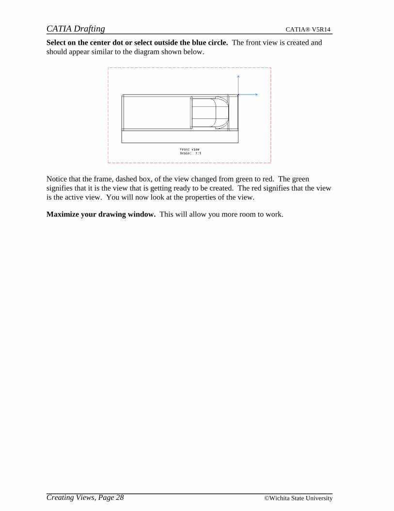
Select on the center dot or select outside the blue circle. The front view is created andshould appear similar to the diagram shown below.
Notice that the frame, dashed box, of the view changed from green to red. The greensignifies that it is the view that is getting ready to be created. The red signifies that the viewis the active view. You will now look at the properties of the view.
Maximize your drawing window. This will allow you more room to work.
CATIA Drafting CATIA® V5R14
Creating Views, Page 29© Wichita State University
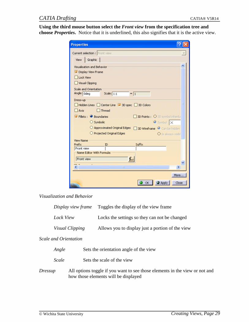
Using the third mouse button select the Front view from the specification tree andchoose Properties. Notice that it is underlined, this also signifies that it is the active view.
Visualization and Behavior
Display view frame Toggles the display of the view frame
Lock View Locks the settings so they can not be changed
Visual Clipping Allows you to display just a portion of the view
Scale and Orientation
Angle Sets the orientation angle of the view
Scale Sets the scale of the view
Dressup All options toggle if you want to see those elements in the view or not andhow those elements will be displayed

CATIA Drafting CATIA® V5R14
Creating Views, Page 30 ©Wichita State University
View Name Allows you to specify a name for the view or the 2D component when valid
Generation Mode
Only generate parts larger than Specifies the minimum size a part can be andstill be generated
Enable occlusion culling Allows you to turn on occlusion culling whichwill only load the parts that are used in thatview instead of loading all of them
View generation mode Changes how the view is generated, Exact isall of the geometry, CGR is the externalappearance of the object and Raster is animage
Generative view style Defines the style that was used to generate this view, thisoption is only available if you have turned off the Preventgenerative view style creation option under pull down menuTools, Options
You will work more with the properties as you develop more views.
Select Close. This will return you to the drawing. You are now ready to create some moreviews.
CATIA Drafting CATIA® V5R14
Creating Views, Page 31© Wichita State University
Projection View
This view is created by using an existing view, usually the front view, and then selecting aposition for the view. The view that gets created depends on where you select. If you selectto the left of the view then you get the left view. Projection views are created orthogonallyto the active view.
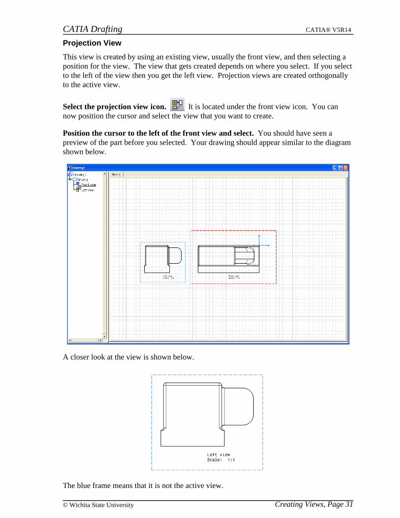
Select the projection view icon. It is located under the front view icon. You cannow position the cursor and select the view that you want to create.
Position the cursor to the left of the front view and select. You should have seen apreview of the part before you selected. Your drawing should appear similar to the diagramshown below.
A closer look at the view is shown below.
The blue frame means that it is not the active view.
CATIA Drafting CATIA® V5R14
Creating Views, Page 32 ©Wichita State University
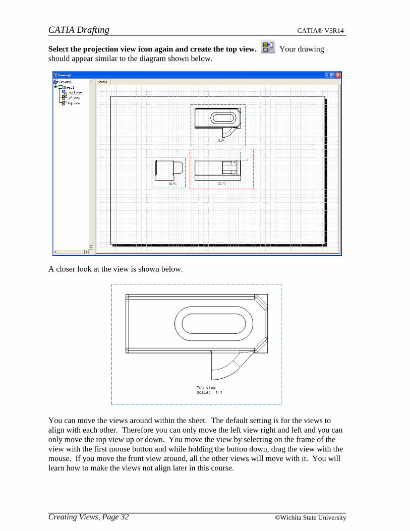
Select the projection view icon again and create the top view. Your drawingshould appear similar to the diagram shown below.
A closer look at the view is shown below.
You can move the views around within the sheet. The default setting is for the views toalign with each other. Therefore you can only move the left view right and left and you canonly move the top view up or down. You move the view by selecting on the frame of theview with the first mouse button and while holding the button down, drag the view with themouse. If you move the front view around, all the other views will move with it. You willlearn how to make the views not align later in this course.

CATIA Drafting CATIA® V5R14
Creating Views, Page 33© Wichita State University
Move the views around so that it appears similar to the diagram shown below.
CATIA Drafting CATIA® V5R14
Creating Views, Page 34 ©Wichita State University
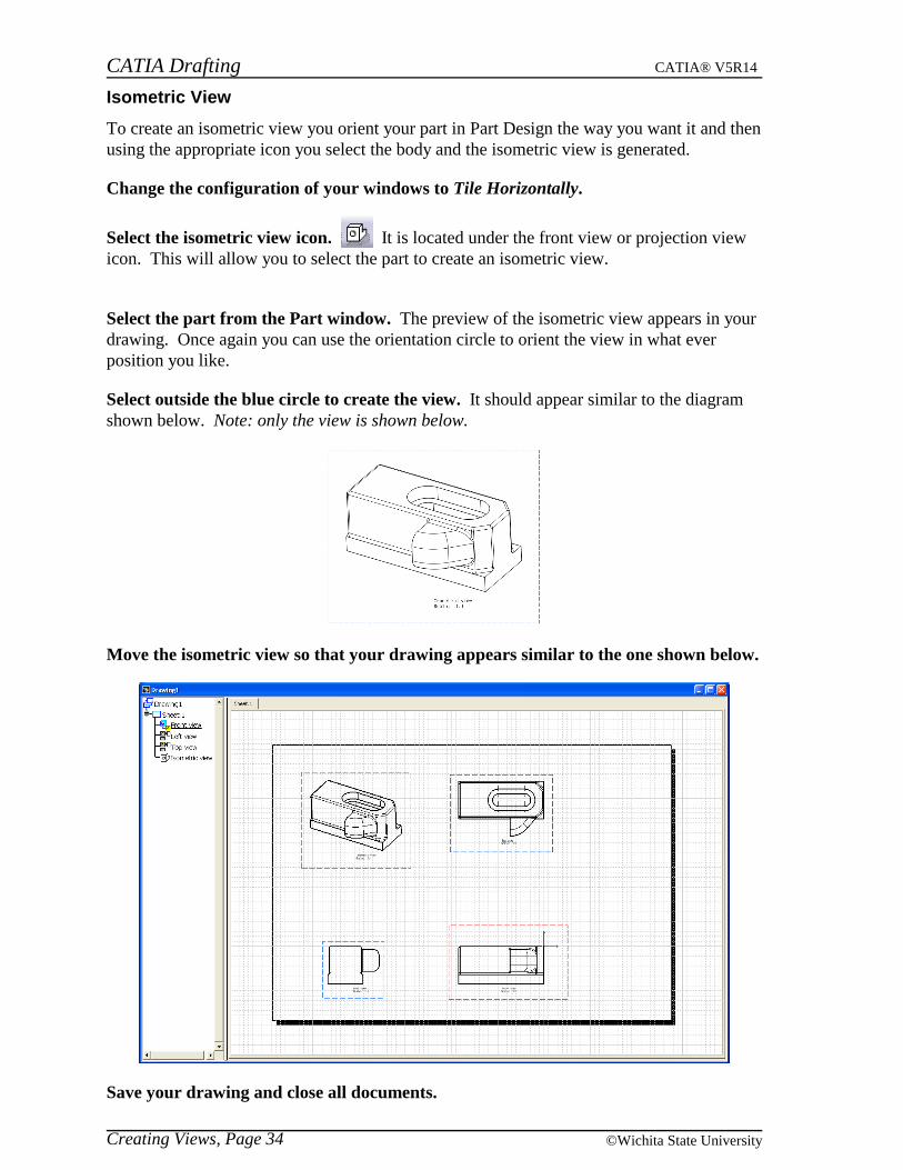
Isometric View
To create an isometric view you orient your part in Part Design the way you want it and thenusing the appropriate icon you select the body and the isometric view is generated.
Change the configuration of your windows to Tile Horizontally.
Select the isometric view icon. It is located under the front view or projection viewicon. This will allow you to select the part to create an isometric view.
Select the part from the Part window. The preview of the isometric view appears in yourdrawing. Once again you can use the orientation circle to orient the view in what everposition you like.
Select outside the blue circle to create the view. It should appear similar to the diagramshown below. Note: only the view is shown below.
Move the isometric view so that your drawing appears similar to the one shown below.
Save your drawing and close all documents.

CATIA Drafting CATIA® V5R14
Creating Views, Page 35© Wichita State University
Advanced Front View
The advanced front view option works exactly the same as the front view option except thatyou can specify additional information during the creation of the view. Examples of theinformation that can be specified are the view name and view scale.
Open the Advanced Front View document. You are going to create a new drawingusing the advanced front view option.
Start a new drawing with an empty sheet, the settings should be ASME Standard, DANSI Sheet Style and Landscape orientation. You do not want any views in the initialdrawing. You can always assume ASME Standard and Landscape orientation for allexercises unless otherwise specified.
Change the configuration of your windows to Tile Horizontally.
Select the advanced front view icon. It is located under the front view or isometricview icon. A View Parameters window appears. You can specify the View name and theScale for the view before you create the actual view.
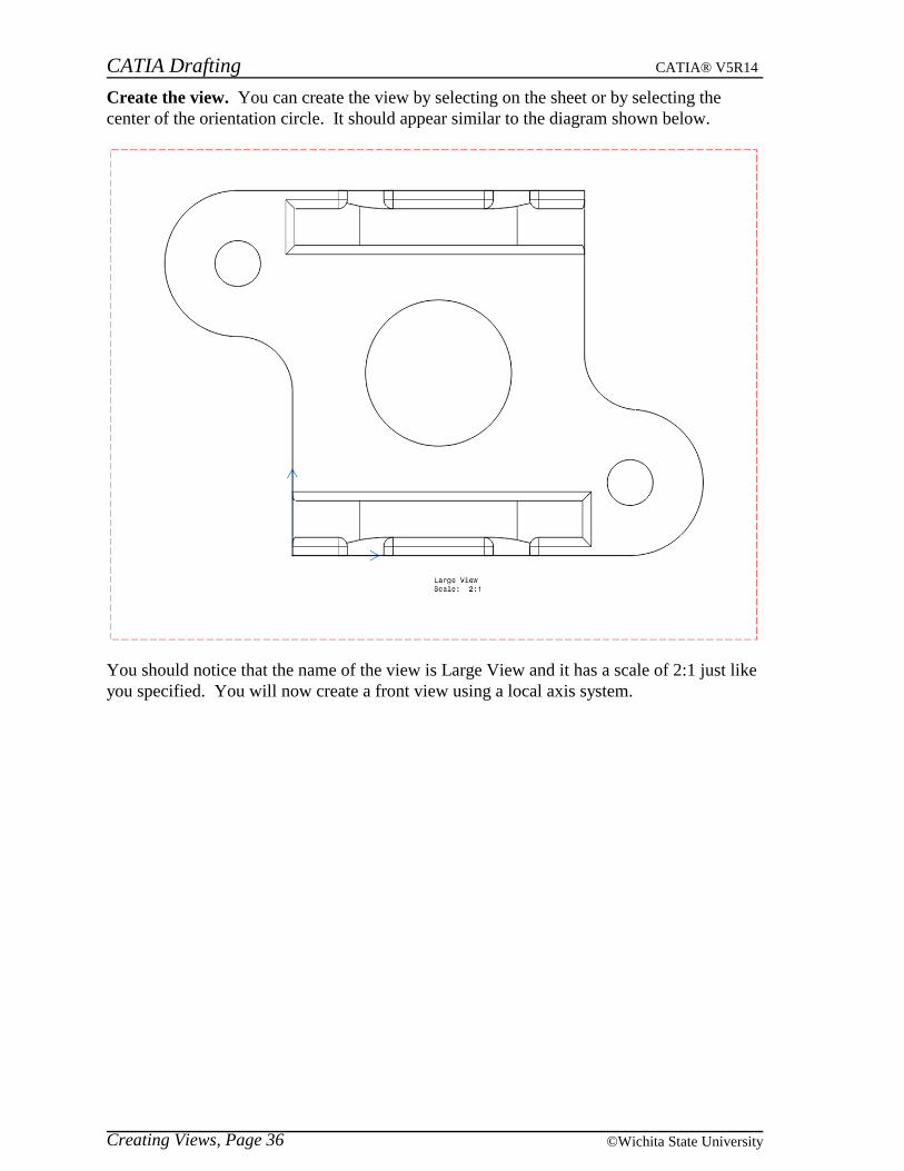
Change the View name to be Large View and the Scale to be 2.0 and select OK.
Select the face shown below.
CATIA Drafting CATIA® V5R14
Creating Views, Page 36 ©Wichita State University
Create the view. You can create the view by selecting on the sheet or by selecting thecenter of the orientation circle. It should appear similar to the diagram shown below.
You should notice that the name of the view is Large View and it has a scale of 2:1 just likeyou specified. You will now create a front view using a local axis system.

CATIA Drafting CATIA® V5R14
Creating Views, Page 37© Wichita State University
Local Axis System
When you create a view from your part, you have the option to select an axis system thatyou want to use as the view axis. If you do not select an axis system before selecting thepart then it will use the global axis as the view origin.
Select the front view icon. You are going to select an axis system first and thendefine the plane for orientation.
Select Axis System.1 from the specification tree in the part and then select the sameface as before. You will probably have to expand the Axis Systems branch in order to seethe actual axis system.
Create the view. The view is created similar to the diagram shown below.
Notice that the view axis is in the location of the local axis system from the part instead ofusing the global axis position.
Save your drawing and close all documents.
CATIA Drafting CATIA® V5R14
Creating Views, Page 38 ©Wichita State University
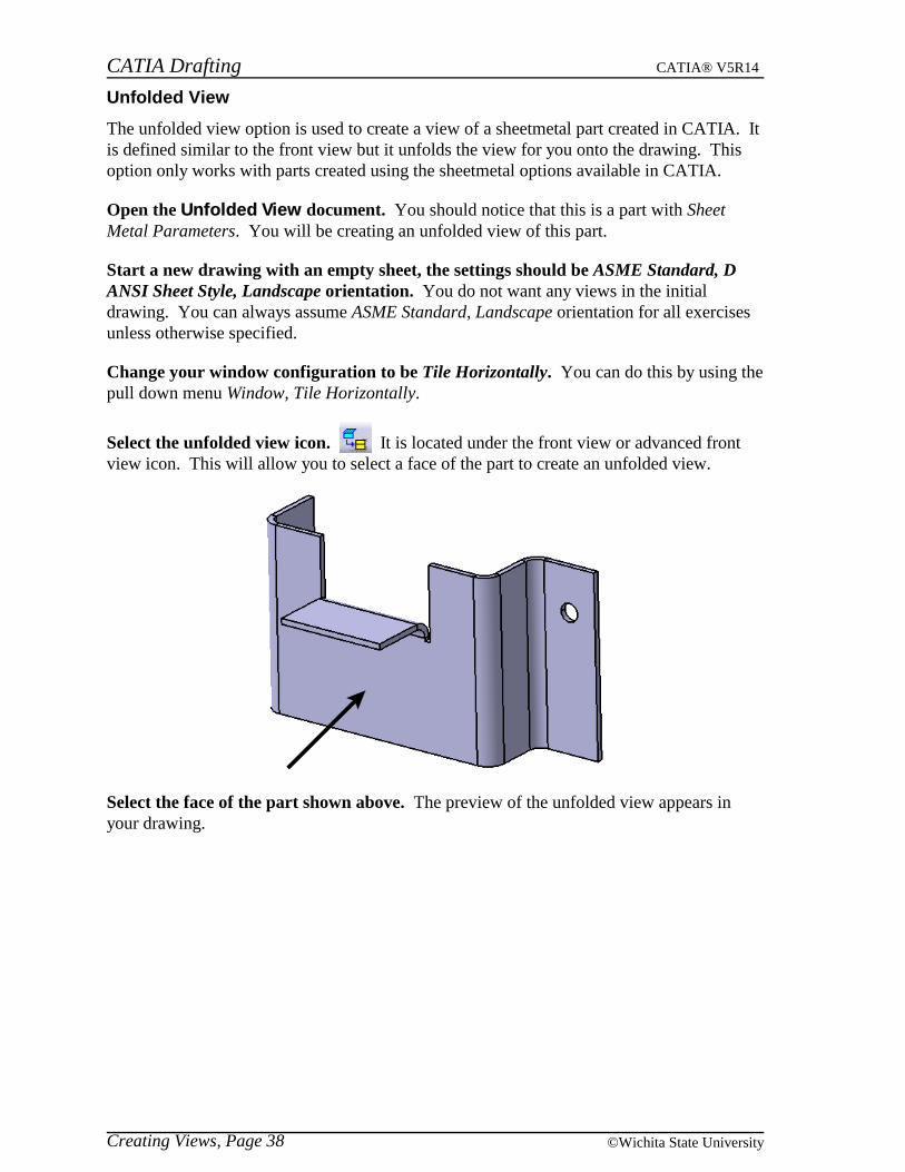
Unfolded View
The unfolded view option is used to create a view of a sheetmetal part created in CATIA. Itis defined similar to the front view but it unfolds the view for you onto the drawing. Thisoption only works with parts created using the sheetmetal options available in CATIA.
Open the Unfolded View document. You should notice that this is a part with SheetMetal Parameters. You will be creating an unfolded view of this part.
Start a new drawing with an empty sheet, the settings should be ASME Standard, DANSI Sheet Style, Landscape orientation. You do not want any views in the initialdrawing. You can always assume ASME Standard, Landscape orientation for all exercisesunless otherwise specified.
Change your window configuration to be Tile Horizontally. You can do this by using thepull down menu Window, Tile Horizontally.
Select the unfolded view icon. It is located under the front view or advanced frontview icon. This will allow you to select a face of the part to create an unfolded view.
Select the face of the part shown above. The preview of the unfolded view appears inyour drawing.

CATIA Drafting CATIA® V5R14
Creating Views, Page 39© Wichita State University
Select outside the view to create the view. It should appear similar to the diagram shownbelow. Note: only the view is shown below.
If the axis lines do not appear in your view, change the Properties of the view to showAxis under Dress Up. Notice that the view shows the sheetmetal part as if it was unfolded.This will give you an accurate view of the actual piece of sheetmetal that would be requiredto bend into the desired shape.
Note: This is very different than creating a front view of this part using the same face. Thediagram below shows you what the front view would have looked like.
It is important to remember that this option only works if the part was created with thesheetmetal options.
Save your drawing and close all documents.
CATIA Drafting CATIA® V5R14
Creating Views, Page 40 ©Wichita State University
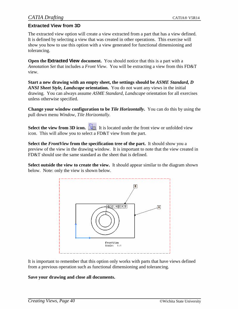
Extracted View from 3D
The extracted view option will create a view extracted from a part that has a view defined.It is defined by selecting a view that was created in other operations. This exercise willshow you how to use this option with a view generated for functional dimensioning andtolerancing.
Open the Extracted View document. You should notice that this is a part with aAnnotation Set that includes a Front View. You will be extracting a view from this FD&Tview.
Start a new drawing with an empty sheet, the settings should be ASME Standard, DANSI Sheet Style, Landscape orientation. You do not want any views in the initialdrawing. You can always assume ASME Standard, Landscape orientation for all exercisesunless otherwise specified.
Change your window configuration to be Tile Horizontally. You can do this by using thepull down menu Window, Tile Horizontally.
Select the view from 3D icon. It is located under the front view or unfolded viewicon. This will allow you to select a FD&T view from the part.
Select the FrontView from the specification tree of the part. It should show you apreview of the view in the drawing window. It is important to note that the view created inFD&T should use the same standard as the sheet that is defined.
Select outside the view to create the view. It should appear similar to the diagram shownbelow. Note: only the view is shown below.
It is important to remember that this option only works with parts that have views definedfrom a previous operation such as functional dimensioning and tolerancing.
Save your drawing and close all documents.
CATIA Drafting CATIA® V5R14
Creating Views, Page 41© Wichita State University
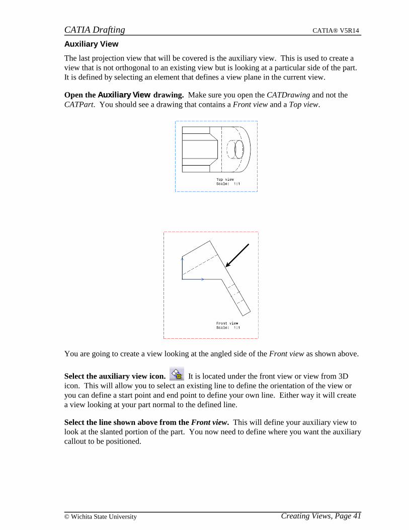
Auxiliary View
The last projection view that will be covered is the auxiliary view. This is used to create aview that is not orthogonal to an existing view but is looking at a particular side of the part.It is defined by selecting an element that defines a view plane in the current view.
Open the Auxiliary View drawing. Make sure you open the CATDrawing and not theCATPart. You should see a drawing that contains a Front view and a Top view.
You are going to create a view looking at the angled side of the Front view as shown above.
Select the auxiliary view icon. It is located under the front view or view from 3Dicon. This will allow you to select an existing line to define the orientation of the view oryou can define a start point and end point to define your own line. Either way it will createa view looking at your part normal to the defined line.
Select the line shown above from the Front view. This will define your auxiliary view tolook at the slanted portion of the part. You now need to define where you want the auxiliarycallout to be positioned.
CATIA Drafting CATIA® V5R14
Creating Views, Page 42 ©Wichita State University
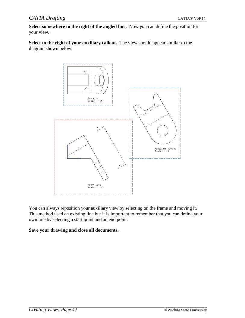
Select somewhere to the right of the angled line. Now you can define the position foryour view.
Select to the right of your auxiliary callout. The view should appear similar to thediagram shown below.
You can always reposition your auxiliary view by selecting on the frame and moving it.This method used an existing line but it is important to remember that you can define yourown line by selecting a start point and an end point.
Save your drawing and close all documents.

CATIA Drafting CATIA® V5R14
Creating Views, Page 43© Wichita State University
Section Views and Section Cuts
Section views and section cuts are views that show the profile of a part at a position, withthe areas that contain material being filled with a pattern. If the part has a material appliedto it then the pattern will display based upon that material. The difference between a sectionview and a section cut is that a section view will show what geometry lies beyond the cutline whereas a section cut will only show what exists at the cut line. The cut line can beeither a single line or it may have jogs in it to show a cut through the same part at differentplaces. Also available are aligned section views and aligned section cuts. The aligned styleallows there to be cut lines that are not parallel and the resulting view is shownperpendicular to the cut lines.
Open the Section Views and Cuts drawing. Make sure you open the CATDrawing andnot the CATPart. You should notice that the Front view is active since the outline is red.You are going to want the Top view to be active since you are going to create a section viewusing the Top view.
Double select on the Top view. The frame of the Top view should change to red. Beforeyou define the cut line you will want to open the Section Views and Cuts part.
Open the Section Views and Cuts part and Tile Horizontally. You do not have to havethis part opened in order to create a section view but it will show you the cut plane in the 3Dpart as you define the cut line.
Select the offset section view icon. This will allow you to define a cut line in yourtop view.
Select to the first location to define the beginning of your section cut as shown below.
Move your mouse over to the second location as shown above but do not select thelocation.
CATIA Drafting CATIA® V5R14
Creating Views, Page 44 ©Wichita State University
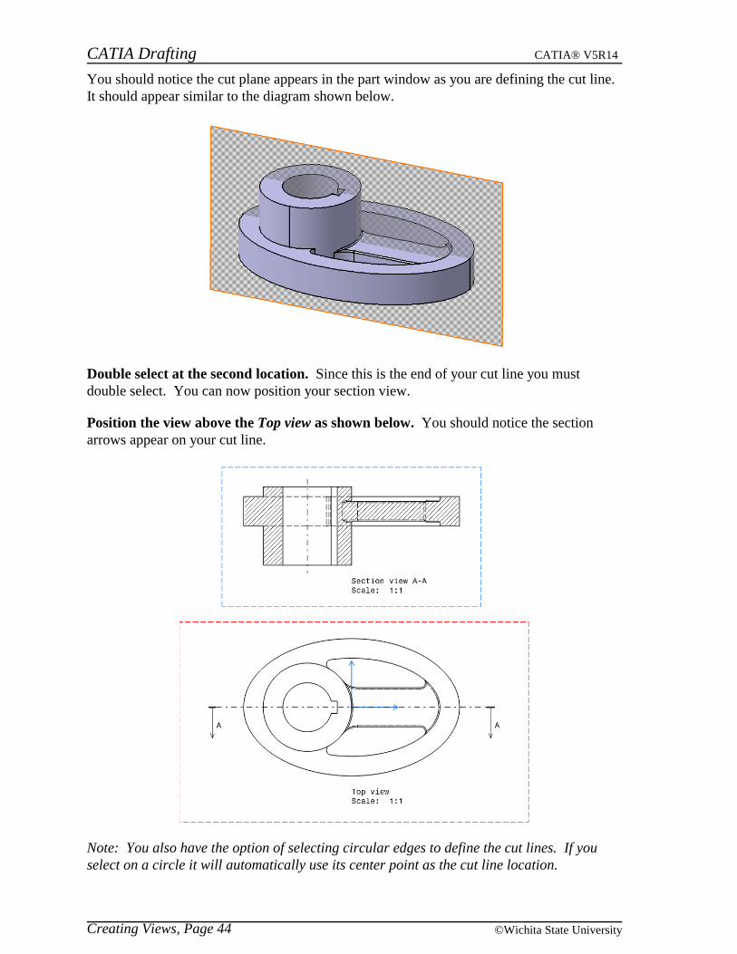
You should notice the cut plane appears in the part window as you are defining the cut line.It should appear similar to the diagram shown below.
Double select at the second location. Since this is the end of your cut line you mustdouble select. You can now position your section view.
Position the view above the Top view as shown below. You should notice the sectionarrows appear on your cut line.
Note: You also have the option of selecting circular edges to define the cut lines. If youselect on a circle it will automatically use its center point as the cut line location.
CATIA Drafting CATIA® V5R14
Creating Views, Page 45© Wichita State University
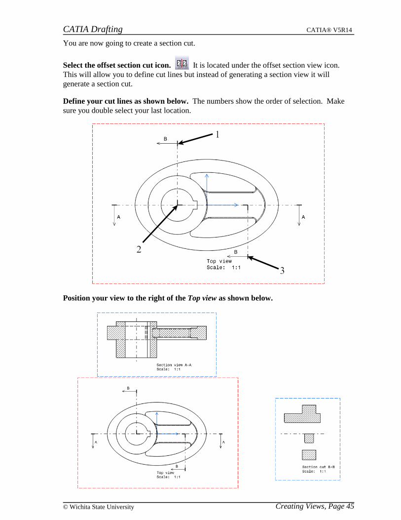
You are now going to create a section cut.
Select the offset section cut icon. It is located under the offset section view icon.This will allow you to define cut lines but instead of generating a section view it willgenerate a section cut.
Define your cut lines as shown below. The numbers show the order of selection. Makesure you double select your last location.
Position your view to the right of the Top view as shown below.

CATIA Drafting CATIA® V5R14
Creating Views, Page 46 ©Wichita State University
You should notice that the section cut does not show any geometry other than what the cutline actually touches. That is the difference between a section cut and a section view.
Make the Front view active. You can do this by double selecting on the Front view. Youare going to create an aligned section view using the Front view.
Select the aligned section view icon. It is located under the offset section view oroffset section cut icon. With this option you can create cut lines that are not parallel.
Define your cut lines as shown below. The numbers show the order of selection. Makesure you double select your last location.
Position the view down and to the left of the Front view. The view is positioned normalto one of the cut lines.
CATIA Drafting CATIA® V5R14
Creating Views, Page 47© Wichita State University
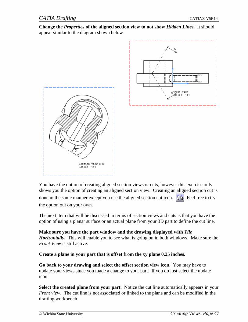
Change the Properties of the aligned section view to not show Hidden Lines. It shouldappear similar to the diagram shown below.
You have the option of creating aligned section views or cuts, however this exercise onlyshows you the option of creating an aligned section view. Creating an aligned section cut is
done in the same manner except you use the aligned section cut icon. Feel free to try
the option out on your own.
The next item that will be discussed in terms of section views and cuts is that you have theoption of using a planar surface or an actual plane from your 3D part to define the cut line.
Make sure you have the part window and the drawing displayed with TileHorizontally. This will enable you to see what is going on in both windows. Make sure theFront View is still active.
Create a plane in your part that is offset from the xy plane 0.25 inches.
Go back to your drawing and select the offset section view icon. You may have toupdate your views since you made a change to your part. If you do just select the updateicon.
Select the created plane from your part. Notice the cut line automatically appears in yourFront view. The cut line is not associated or linked to the plane and can be modified in thedrafting workbench.
CATIA Drafting CATIA® V5R14
Creating Views, Page 48 ©Wichita State University
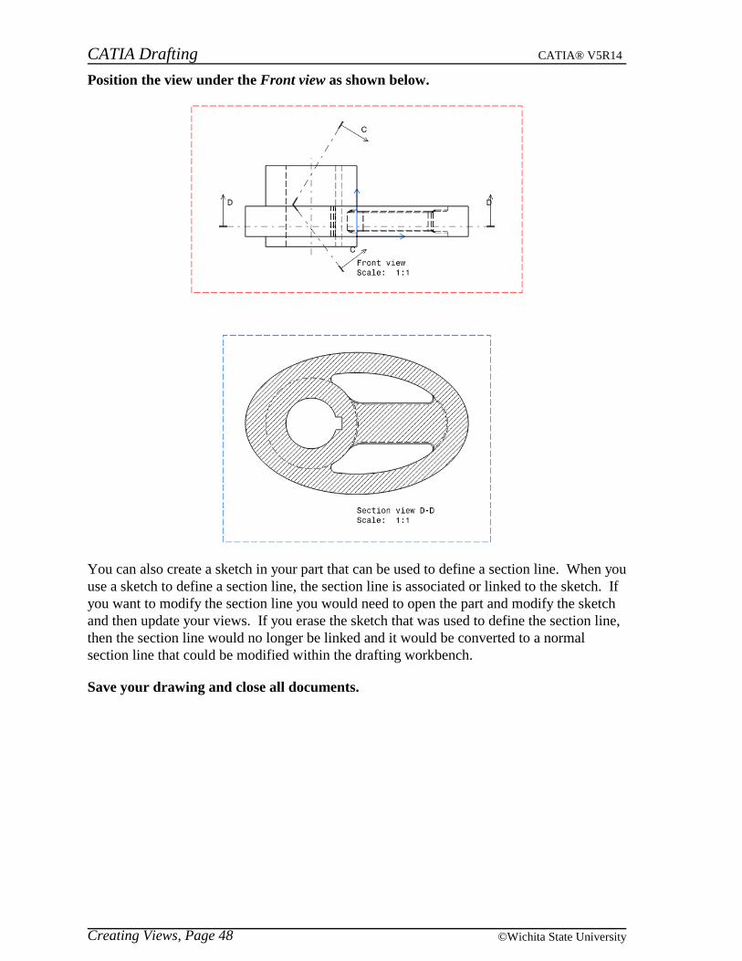
Position the view under the Front view as shown below.
You can also create a sketch in your part that can be used to define a section line. When youuse a sketch to define a section line, the section line is associated or linked to the sketch. Ifyou want to modify the section line you would need to open the part and modify the sketchand then update your views. If you erase the sketch that was used to define the section line,then the section line would no longer be linked and it would be converted to a normalsection line that could be modified within the drafting workbench.
Save your drawing and close all documents.
CATIA Drafting CATIA® V5R14
Creating Views, Page 49© Wichita State University
Detail Views
A detail view is a partial view of a part that is usually at a higher scale to make it easier tosee. CATIA allows for the creation of four different detail views. You can either use acircle or a profile callout. Besides choosing what you want to use as a callout, you caneither create the detail view so that it uses the 2D projection to determine the detail view orit can generate the view from the 3D definition. The quick detail options use the 2Dprojection to generate the view.
Open the Detail Views drawing. Make sure you open the CATDrawing and not theCATPart. You should notice that the Front view is active since the outline is red. You aregoing to create a couple of detail views to draw attention to various areas that may be hardto understand with the current views.
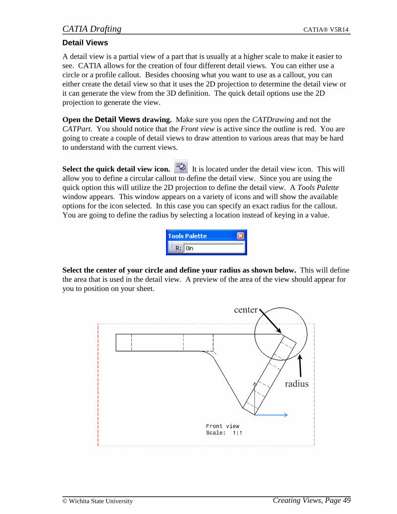
Select the quick detail view icon. It is located under the detail view icon. This willallow you to define a circular callout to define the detail view. Since you are using thequick option this will utilize the 2D projection to define the detail view. A Tools Palettewindow appears. This window appears on a variety of icons and will show the availableoptions for the icon selected. In this case you can specify an exact radius for the callout.You are going to define the radius by selecting a location instead of keying in a value.
Select the center of your circle and define your radius as shown below. This will definethe area that is used in the detail view. A preview of the area of the view should appear foryou to position on your sheet.
CATIA Drafting CATIA® V5R14
Creating Views, Page 50 ©Wichita State University
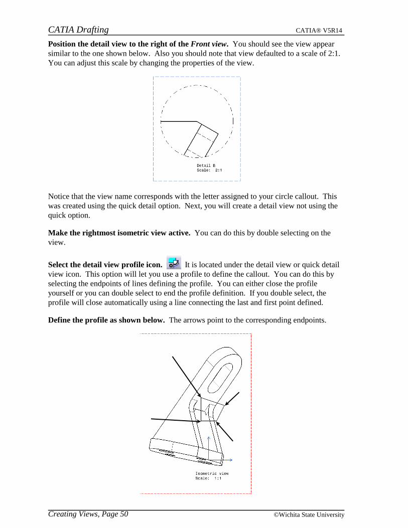
Position the detail view to the right of the Front view. You should see the view appearsimilar to the one shown below. Also you should note that view defaulted to a scale of 2:1.You can adjust this scale by changing the properties of the view.
Notice that the view name corresponds with the letter assigned to your circle callout. Thiswas created using the quick detail option. Next, you will create a detail view not using thequick option.
Make the rightmost isometric view active. You can do this by double selecting on theview.
Select the detail view profile icon. It is located under the detail view or quick detailview icon. This option will let you use a profile to define the callout. You can do this byselecting the endpoints of lines defining the profile. You can either close the profileyourself or you can double select to end the profile definition. If you double select, theprofile will close automatically using a line connecting the last and first point defined.
Define the profile as shown below. The arrows point to the corresponding endpoints.
CATIA Drafting CATIA® V5R14
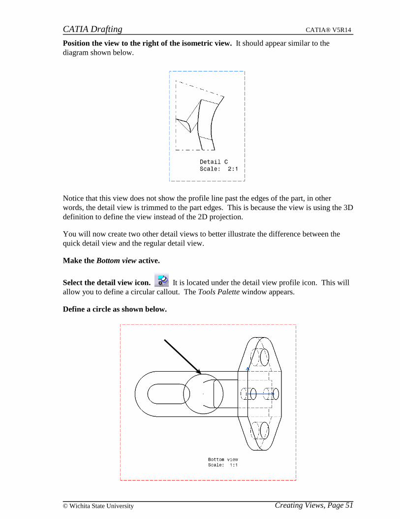
Creating Views, Page 51© Wichita State University
Position the view to the right of the isometric view. It should appear similar to thediagram shown below.
Notice that this view does not show the profile line past the edges of the part, in otherwords, the detail view is trimmed to the part edges. This is because the view is using the 3Ddefinition to define the view instead of the 2D projection.
You will now create two other detail views to better illustrate the difference between thequick detail view and the regular detail view.
Make the Bottom view active.
Select the detail view icon. It is located under the detail view profile icon. This willallow you to define a circular callout. The Tools Palette window appears.
Define a circle as shown below.

CATIA Drafting CATIA® V5R14
Creating Views, Page 52 ©Wichita State University
Position the detail view to the right of the Detail B view. It should appear similar to thediagram shown below. Once again, notice that the view is trimmed to the edges of yourpart. Unlike the quick detail option that you used the first time which shows the entirecircle.
Make the leftmost isometric view active.
Select the quick detail view profile icon. It is located under the detail view icon.This will allow you to define a profile to use as the callout.
Define a profile similar to the one shown below.
CATIA Drafting CATIA® V5R14
Creating Views, Page 53© Wichita State University
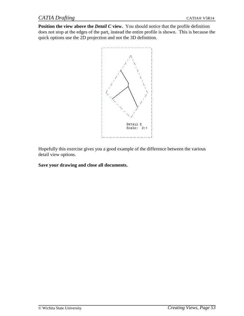
Position the view above the Detail C view. You should notice that the profile definitiondoes not stop at the edges of the part, instead the entire profile is shown. This is because thequick options use the 2D projection and not the 3D definition.
Hopefully this exercise gives you a good example of the difference between the variousdetail view options.
Save your drawing and close all documents.
CATIA Drafting CATIA® V5R14
Creating Views, Page 54 ©Wichita State University
Clipping Views
Clipping views are similar to detail views in the way they can be defined. You have theoption of either using a circle or a profile to define the clipping area just like the detail view.However the difference is that a clipping view actually changes the current view to justcontain the clipping area. This option is used when the whole part would be too large andyou are only interested in a section of the part. By default the clipped view will maintain itsscale ratio.
Open the Clipping Views drawing. Make sure you open the CATDrawing and not theCATPart. You should notice that the Auxiliary view is active since the outline is red.
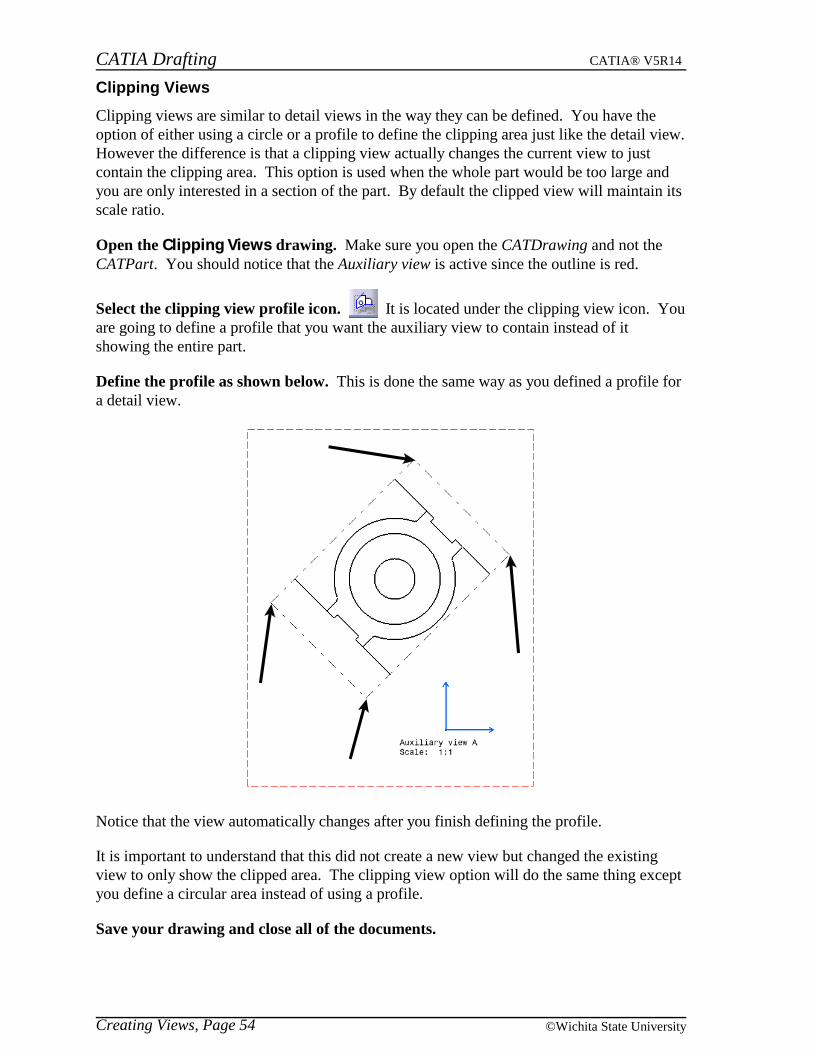
Select the clipping view profile icon. It is located under the clipping view icon. Youare going to define a profile that you want the auxiliary view to contain instead of itshowing the entire part.
Define the profile as shown below. This is done the same way as you defined a profile fora detail view.
Notice that the view automatically changes after you finish defining the profile.
It is important to understand that this did not create a new view but changed the existingview to only show the clipped area. The clipping view option will do the same thing exceptyou define a circular area instead of using a profile.
Save your drawing and close all of the documents.

CATIA Drafting CATIA® V5R14
Creating Views, Page 55© Wichita State University
Broken View
A broken view is used when you have a long section that is not important to be seen in theview. This option will allow you to define the two ends of the break and then it will modifythe view so that section will not appear. Breakout lines are generated to show where thebreaks occur.
Open the Broken View drawing. Make sure you open the CATDrawing and not theCATPart. You should notice that the Front view is active and that the Left view extendspast the sheet. You are going to use the broken view option to modify the Left view to showthe two ends of the beam leaving out the middle section.
Make the Left view active.
Select the broken view icon. You are going to define two break lines that will definethe area to remove when modifying the view.
Select inside the beam edges at the location shown below. Once you select the locationyou can either create the broken view to break horizontally or vertically. In this case youwant the break to be vertical.
Select above the previous location. You will now be able to define the other break line sothat it can remove the area between them.
Select inside the beam edges at the location shown below.
Select outside the view on the sheet. The broken view is generated. However the view isstill partially off the sheet and the label is to the right of the actual geometry.
CATIA Drafting CATIA® V5R14
Creating Views, Page 56 ©Wichita State University
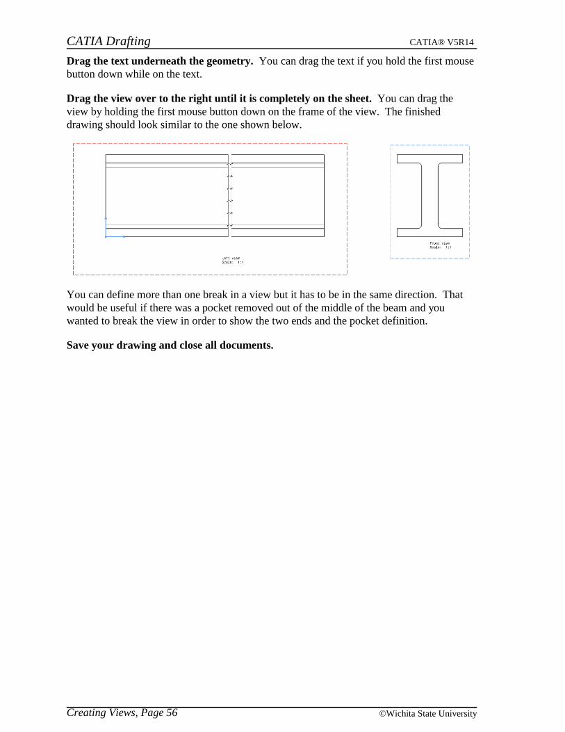
Drag the text underneath the geometry. You can drag the text if you hold the first mousebutton down while on the text.
Drag the view over to the right until it is completely on the sheet. You can drag theview by holding the first mouse button down on the frame of the view. The finisheddrawing should look similar to the one shown below.
You can define more than one break in a view but it has to be in the same direction. Thatwould be useful if there was a pocket removed out of the middle of the beam and youwanted to break the view in order to show the two ends and the pocket definition.
Save your drawing and close all documents.
CATIA Drafting CATIA® V5R14
Creating Views, Page 57© Wichita State University
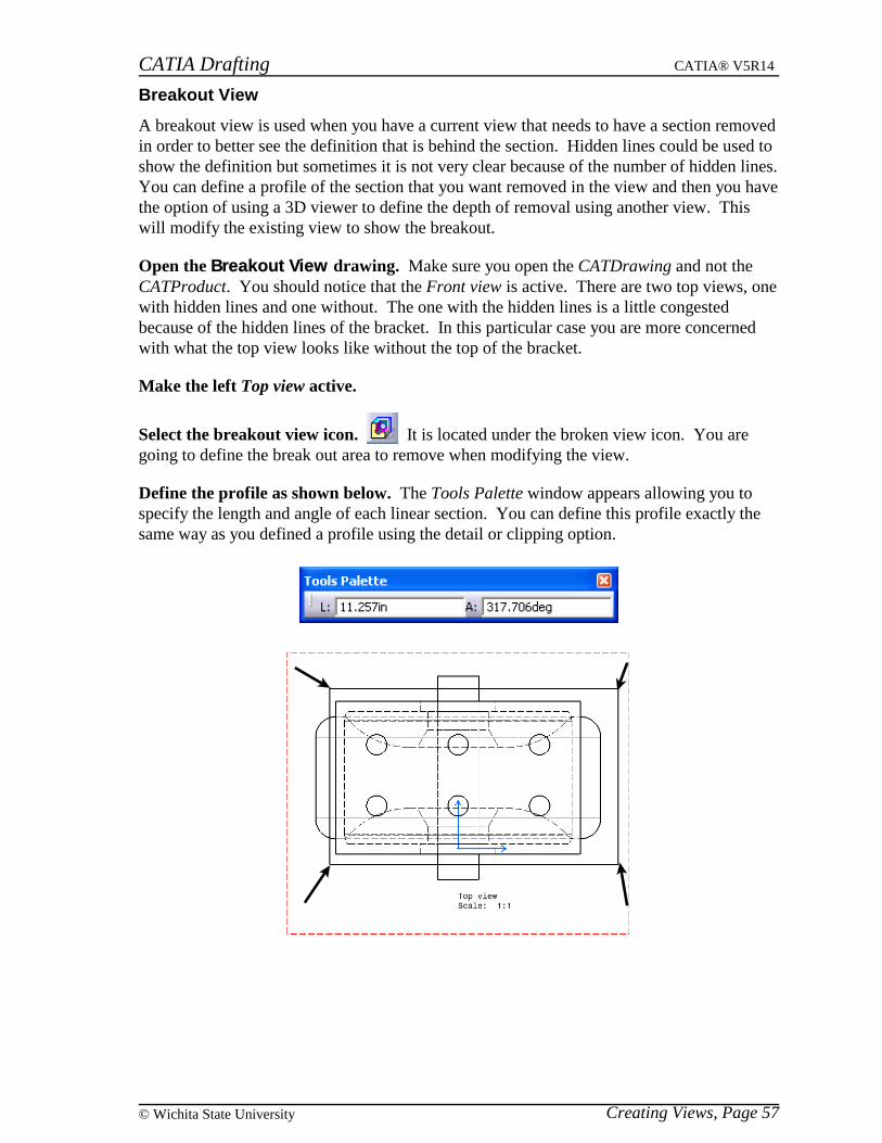
Breakout View
A breakout view is used when you have a current view that needs to have a section removedin order to better see the definition that is behind the section. Hidden lines could be used toshow the definition but sometimes it is not very clear because of the number of hidden lines.You can define a profile of the section that you want removed in the view and then you havethe option of using a 3D viewer to define the depth of removal using another view. Thiswill modify the existing view to show the breakout.
Open the Breakout View drawing. Make sure you open the CATDrawing and not theCATProduct. You should notice that the Front view is active. There are two top views, onewith hidden lines and one without. The one with the hidden lines is a little congestedbecause of the hidden lines of the bracket. In this particular case you are more concernedwith what the top view looks like without the top of the bracket.
Make the left Top view active.
Select the breakout view icon. It is located under the broken view icon. You aregoing to define the break out area to remove when modifying the view.
Define the profile as shown below. The Tools Palette window appears allowing you tospecify the length and angle of each linear section. You can define this profile exactly thesame way as you defined a profile using the detail or clipping option.
CATIA Drafting CATIA® V5R14
Creating Views, Page 58 ©Wichita State University
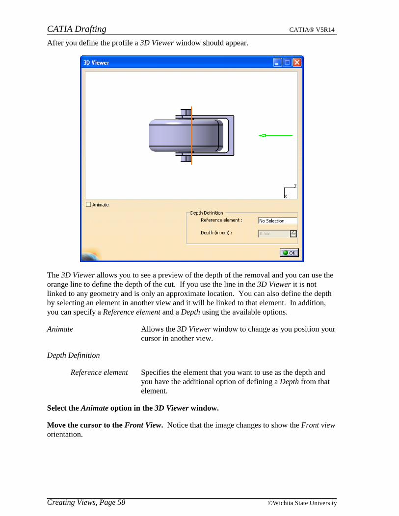
After you define the profile a 3D Viewer window should appear.
The 3D Viewer allows you to see a preview of the depth of the removal and you can use theorange line to define the depth of the cut. If you use the line in the 3D Viewer it is notlinked to any geometry and is only an approximate location. You can also define the depthby selecting an element in another view and it will be linked to that element. In addition,you can specify a Reference element and a Depth using the available options.
Animate Allows the 3D Viewer window to change as you position yourcursor in another view.
Depth Definition
Reference element Specifies the element that you want to use as the depth andyou have the additional option of defining a Depth from thatelement.
Select the Animate option in the 3D Viewer window.
Move the cursor to the Front View. Notice that the image changes to show the Front vieworientation.
CATIA Drafting CATIA® V5R14
Creating Views, Page 59© Wichita State University
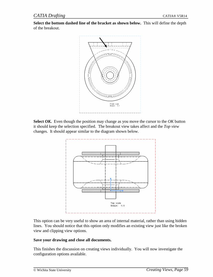
Select the bottom dashed line of the bracket as shown below. This will define the depthof the breakout.
Select OK. Even though the position may change as you move the cursor to the OK buttonit should keep the selection specified. The breakout view takes affect and the Top viewchanges. It should appear similar to the diagram shown below.
This option can be very useful to show an area of internal material, rather than using hiddenlines. You should notice that this option only modifies an existing view just like the brokenview and clipping view options.
Save your drawing and close all documents.
This finishes the discussion on creating views individually. You will now investigate theconfiguration options available.
CATIA Drafting CATIA® V5R14
Creating Views, Page 60 ©Wichita State University
Configuration of Views
There are four options to create a configuration of views on your sheet. Three of them arepreset configurations and the other one is a creation wizard that lets you define theconfiguration. The three that are preset are Front, Top and Left; Front, Bottom and Right;and All views. You will experiment with the presets and then create your ownconfiguration using the wizard.
Open the Configuration part. You will be creating views for this part.
Start a new drawing with an empty sheet using the same options as before. You do notwant any views in the initial drawing.
Change your window configuration to be Tile Horizontally.
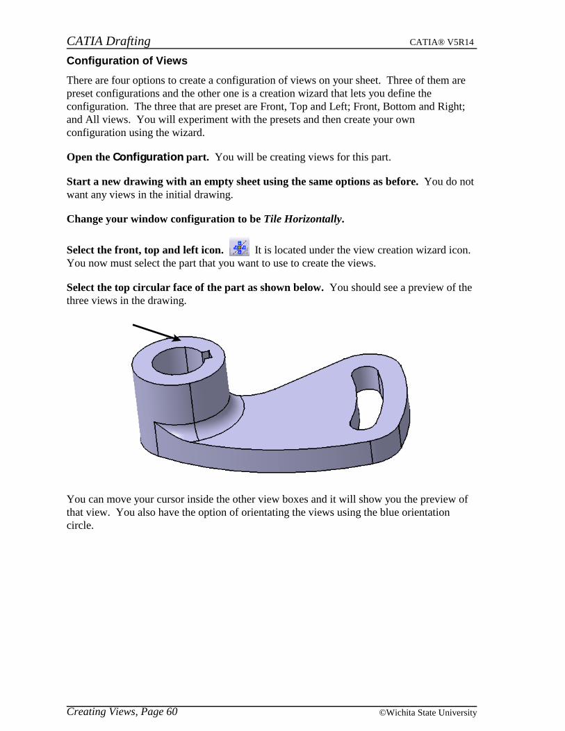
Select the front, top and left icon. It is located under the view creation wizard icon.You now must select the part that you want to use to create the views.
Select the top circular face of the part as shown below. You should see a preview of thethree views in the drawing.
You can move your cursor inside the other view boxes and it will show you the preview ofthat view. You also have the option of orientating the views using the blue orientationcircle.

CATIA Drafting CATIA® V5R14
Creating Views, Page 61© Wichita State University
Select outside one of the views. This creates all three views.
Select undo until the three views disappear. You are going to use the other two presetoptions next.
Select the front, bottom and right icon. It is located under the view creation wizardor front, top and left icon.
Select the same face as you did before.
CATIA Drafting CATIA® V5R14
Creating Views, Page 62 ©Wichita State University
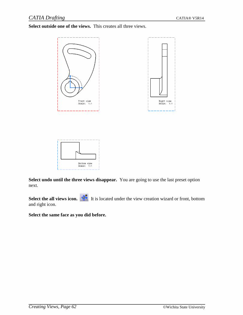
Select outside one of the views. This creates all three views.
Select undo until the three views disappear. You are going to use the last preset optionnext.
Select the all views icon. It is located under the view creation wizard or front, bottomand right icon.
Select the same face as you did before.
CATIA Drafting CATIA® V5R14
Creating Views, Page 63© Wichita State University
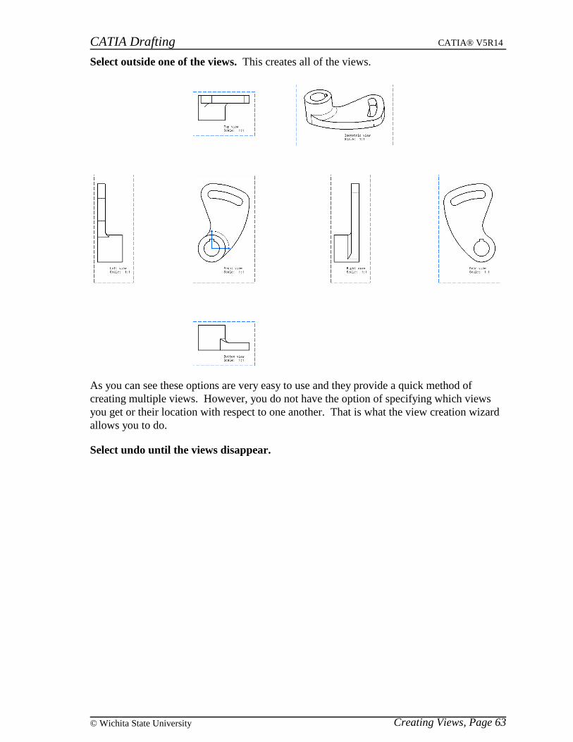
Select outside one of the views. This creates all of the views.
As you can see these options are very easy to use and they provide a quick method ofcreating multiple views. However, you do not have the option of specifying which viewsyou get or their location with respect to one another. That is what the view creation wizardallows you to do.
Select undo until the views disappear.

CATIA Drafting CATIA® V5R14
Creating Views, Page 64 ©Wichita State University
Select the view creation wizard icon. It is located under the all views icon. Thiswill open a View Wizard window.
Front, Right, Top configuration
Front, Left, Top configuration
Front, Right, Bottom configuration
Front, Left, Bottom configuration
All views except Rear configuration
All views configuration
Third angle projection Determines how the projection views will be created
Toggles link to main view Toggles between having the projection views linked tothe main view or not having them linked
Minimum distance between each view The minimum distance between view frames
The main view is what all of the projection views will be linked to, meaning if you movethat view all the other views will move with it. You can specify which view is the mainview by selecting the view with the third mouse button and choosing the Set as main viewoption. It is important to note that only the front view or isometric view can be used as themain view.
You can also remove a view from the configuration that you choose by selecting the viewwith the third mouse button and choosing the Delete option.
CATIA Drafting CATIA® V5R14
Creating Views, Page 65© Wichita State University
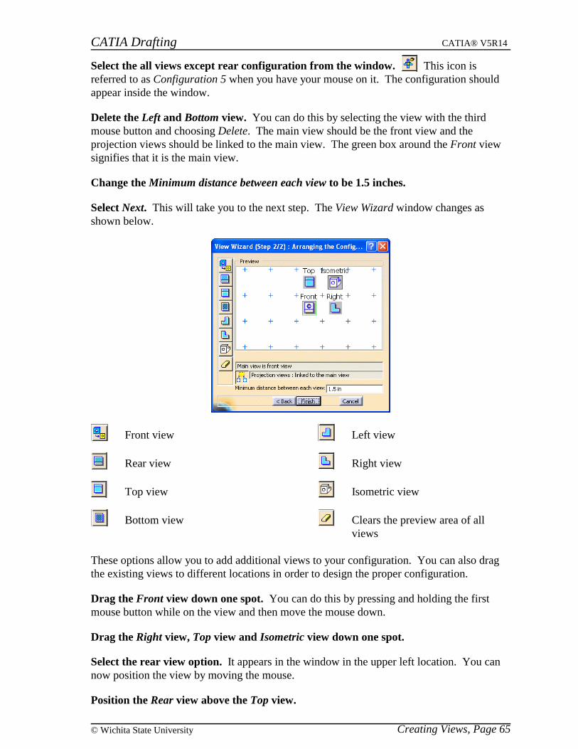
Select the all views except rear configuration from the window. This icon isreferred to as Configuration 5 when you have your mouse on it. The configuration shouldappear inside the window.
Delete the Left and Bottom view. You can do this by selecting the view with the thirdmouse button and choosing Delete. The main view should be the front view and theprojection views should be linked to the main view. The green box around the Front viewsignifies that it is the main view.
Change the Minimum distance between each view to be 1.5 inches.
Select Next. This will take you to the next step. The View Wizard window changes asshown below.
Front view
Rear view
Top view
Bottom view
Left view
Right view
Isometric view
Clears the preview area of allviews
These options allow you to add additional views to your configuration. You can also dragthe existing views to different locations in order to design the proper configuration.
Drag the Front view down one spot. You can do this by pressing and holding the firstmouse button while on the view and then move the mouse down.
Drag the Right view, Top view and Isometric view down one spot.
Select the rear view option. It appears in the window in the upper left location. You cannow position the view by moving the mouse.
Position the Rear view above the Top view.
CATIA Drafting CATIA® V5R14
Creating Views, Page 66 ©Wichita State University
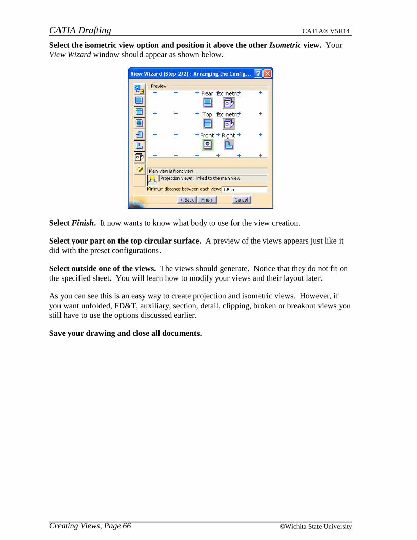
Select the isometric view option and position it above the other Isometric view. YourView Wizard window should appear as shown below.
Select Finish. It now wants to know what body to use for the view creation.
Select your part on the top circular surface. A preview of the views appears just like itdid with the preset configurations.
Select outside one of the views. The views should generate. Notice that they do not fit onthe specified sheet. You will learn how to modify your views and their layout later.
As you can see this is an easy way to create projection and isometric views. However, ifyou want unfolded, FD&T, auxiliary, section, detail, clipping, broken or breakout views youstill have to use the options discussed earlier.
Save your drawing and close all documents.
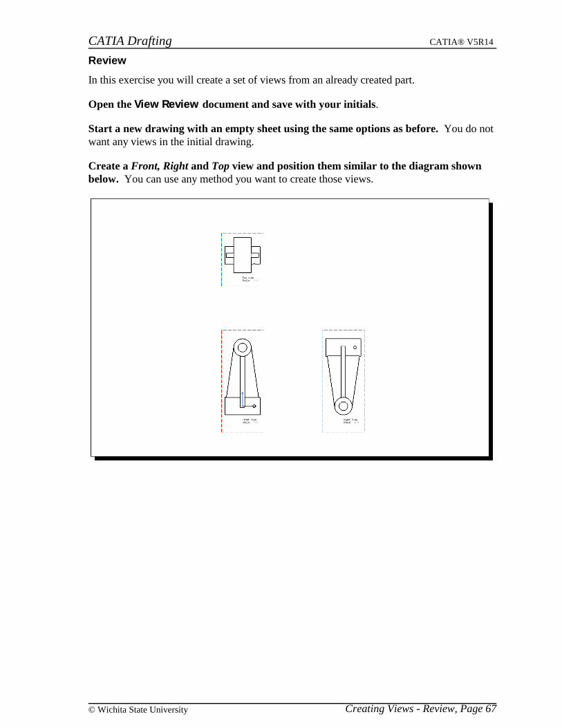
CATIA Drafting CATIA® V5R14
Creating Views - Review, Page 67© Wichita State University
Review
In this exercise you will create a set of views from an already created part.
Open the View Review document and save with your initials.
Start a new drawing with an empty sheet using the same options as before. You do notwant any views in the initial drawing.
Create a Front, Right and Top view and position them similar to the diagram shownbelow. You can use any method you want to create those views.

CATIA Drafting CATIA® V5R14
Creating Views - Review, Page 68 ©Wichita State University
Create a section view going through the center of the Front view and position it asshown below.
Create a detail view and position it as shown below. Remember to make the sectionview active before you try to create the detail view from it.
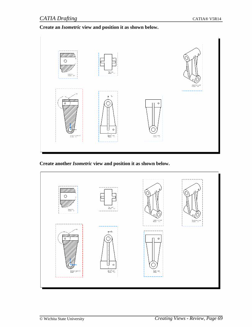
CATIA Drafting CATIA® V5R14
Creating Views - Review, Page 69© Wichita State University
Create an Isometric view and position it as shown below.
Create another Isometric view and position it as shown below.

CATIA Drafting CATIA® V5R14
Creating Views - Review, Page 70 ©Wichita State University
Modify the last view to only show the section that is shown in the diagram below.
Create another Isometric view and position it as shown below.

CATIA Drafting CATIA® V5R14
Creating Views - Review, Page 71© Wichita State University
Make that view a broken view as shown below.
Make sure you save this drawing as Review with your initials. This drawing will beused in the next section of the book and it is important that you have this drawing available.
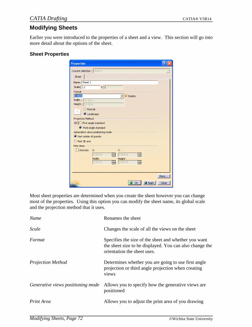
CATIA Drafting CATIA® V5R14
Modifying Sheets, Page 72 ©Wichita State University
Modifying Sheets
Earlier you were introduced to the properties of a sheet and a view. This section will go intomore detail about the options of the sheet.
Sheet Properties
Most sheet properties are determined when you create the sheet however you can changemost of the properties. Using this option you can modify the sheet name, its global scaleand the projection method that it uses.
Name Renames the sheet
Scale Changes the scale of all the views on the sheet
Format Specifies the size of the sheet and whether you wantthe sheet size to be displayed. You can also change theorientation the sheet uses.
Projection Method Determines whether you are going to use first angleprojection or third angle projection when creatingviews
Generative views positioning mode Allows you to specify how the generative views arepositioned
Print Area Allows you to adjust the print area of you drawing
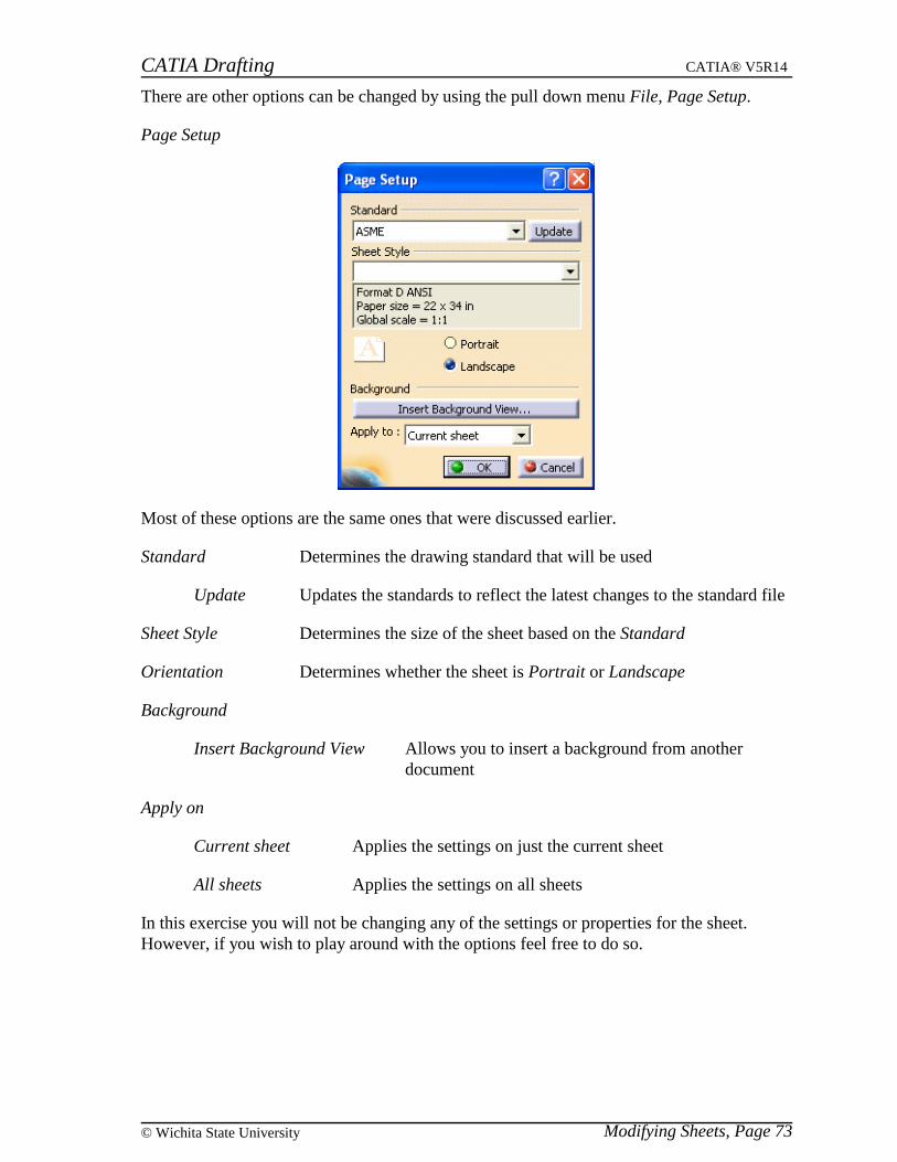
CATIA Drafting CATIA® V5R14
Modifying Sheets, Page 73© Wichita State University
There are other options can be changed by using the pull down menu File, Page Setup.
Page Setup
Most of these options are the same ones that were discussed earlier.
Standard Determines the drawing standard that will be used
Update Updates the standards to reflect the latest changes to the standard file
Sheet Style Determines the size of the sheet based on the Standard
Orientation Determines whether the sheet is Portrait or Landscape
Background
Insert Background View Allows you to insert a background from anotherdocument
Apply on
Current sheet Applies the settings on just the current sheet
All sheets Applies the settings on all sheets
In this exercise you will not be changing any of the settings or properties for the sheet.However, if you wish to play around with the options feel free to do so.

CATIA Drafting CATIA® V5R14
Modifying Views, Page 74 ©Wichita State University
Modifying Views
The view properties window was discussed earlier in the book but this section will show theoptions and then proceed with the exercise of modifying some of these properties.
View Properties
Visualization and Behavior
Display view frame Toggles the display of the view frame
Lock View Locks the settings so they can not be changed
Visual Clipping Allows you to display just a portion of the view
Scale and Orientation
Angle Sets the orientation angle of the view
Scale Sets the scale of the view
Dressup All options toggle if you want to see those elements in the view or not andhow those elements will be displayed
CATIA Drafting CATIA® V5R14
Modifying Views, Page 75© Wichita State University
View Name Allows you to specify a name for the view or the 2D component when valid
Generation Mode
Only generate parts larger than Specifies the minimum size a part can be andstill be generated
Enable occlusion culling Allows you to turn on occlusion culling whichwill only load the parts that are used in thatview instead of loading all of them
View generation mode Changes how the view is generated, Exact isall of the geometry, CGR is the externalappearance of the object and Raster is animage
Generative view style Defines the style that was used to generate this view, thisoption is only available if you have turned off the Preventgenerative view style creation option under pull down menuTools, Options
Open your Review drawing if it is not still open. This is the drawing that you did in anearlier exercise. This drawing should contain a Front, Top, Right, Section, Detail, and threeIsometric views. One of the isometric views was clipped and another one was broken. Thefirst thing you are going to modify is the display of hidden lines. If you do not have thisdrawing there is an existing one in the class models directory.
Select the Front, Top, Right and the clipped Isometric view. You can do this by holdingthe Ctrl key down and selecting them.
Press the third mouse button and select Properties. You have to be on one of the viewsin the specification tree.
Go to the View tab and under Dressup toggle the Hidden Lines option on and selectApply. The hidden lines should appear in all four views. This is a nice feature in that youcan change the properties of multiple views at the same time instead of having to change theproperties one view at a time.

CATIA Drafting CATIA® V5R14
Modifying Views, Page 76 ©Wichita State University
Select OK. The drawing should appear similar to the diagram shown below.
Next you are going to display the center lines in the front and the right view.
Select the Front and Right view and change the properties to show Center Lines. Youshould notice the center lines appear at the center of every circle. Now you are going todisplay the axis lines in the top view.
Change the properties of the top view to show Axis lines. You should notice axis linesappear down the center of all the holes.
Go to the properties of the clipped isometric view. You are going to change the name ofthis view and its scale.
Change its name from Isometric view to Clipped view and select Apply. You shouldnotice the name change in the view and in the specification tree.
Change the scale from 1:1 to 2 and select Apply. Notice the view grew twice its size andthe notation for the view states that is has a Scale: 2:1.
Select OK. Most likely this view is interfering with some of the other views. You are goingto drag the views to reposition them.
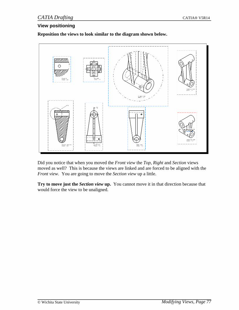
CATIA Drafting CATIA® V5R14
Modifying Views, Page 77© Wichita State University
View positioning
Reposition the views to look similar to the diagram shown below.
Did you notice that when you moved the Front view the Top, Right and Section viewsmoved as well? This is because the views are linked and are forced to be aligned with theFront view. You are going to move the Section view up a little.
Try to move just the Section view up. You cannot move it in that direction because thatwould force the view to be unaligned.

CATIA Drafting CATIA® V5R14
Modifying Views, Page 78 ©Wichita State University
Using the third mouse button select on the Section view and choose View Positioning.The following options appear.
Set Relative Position Positions the view relative to a location
Position Independently of Reference View Breaks the positional link between views
Superpose Allows one view to be put on top of anotherwith the origins of each view at the samelocation
Align Views Using Elements Aligns views using the geometry in the views
Select the Position Independently of Reference View option. This will allow the view tomove to an unaligned position.
Now move the Section view up a little. The view moves up. You have the option of goingback to the View Positioning option and choosing Position According to Reference View ifyou want the view to be aligned again. You are going to position the top line of the Detailview to be aligned with the top line of the Top view.
Using the third mouse button select on the Detail view and choose View Positioning,Align Views Using Elements. You can now specify the two elements that you want toalign.
Select the top horizontal line in the Detail view and the top horizontal line in the Topview. The Detail view moves to align the two lines. If you would have selected the line inthe Top view first then the Top view would have moved instead of the Detail view.
You can also place one view on top of another using the origins of the views.

CATIA Drafting CATIA® V5R14
Modifying Views, Page 79© Wichita State University
Using the third mouse button select on the Section view and choose View Positioning,Superpose. You can now choose which view you want this one to position itself on top of.
Select the Front view. The view is positioned on top of the Front view.
Select the undo icon. The Section view moves back to its previous position.
There is another option that can be used for positioning views but it is not used very oftenand it will be covered with positioning annotations. The element positioning icon can be
found under the Positioning toolbar. You will probably have to turn that toolbar on to
see the icon.

CATIA Drafting CATIA® V5R14
Modifying Views, Page 80 ©Wichita State University
Locating Views
On large drawings there are times when it is hard to tell where a corresponding detail orsection view is located. Also, it can be hard to tell where the parent view of a detail orsection view is located. A couple of options to help you locate views will be covered.
Press the third mouse button while on the section line callout in the Front view.Options appear.
Select the Locate Resulting View option. The corresponding section view is shown.
Press the third mouse button while on the Section view. Options appear.
Select the Locate Reference View option. The parent view of the section view appears,which is the Front view.
View Names
You are going to move around some of the view names so that they are in positions that areeasier to read. There are a lot of properties that you can change involving the text but theywill be covered later.
Press and hold the first mouse button while on the view name for the Front view anddrag the name down away from the section line. This should make it easier to read theview name along with making it easier to see the section arrow.
In the Clipped view, select the view name and press Delete. You are going to haveCATIA recreate the view name.
Using the third mouse button select on the Clipped view and select Clipped view object,Add View Name. Notice the view name reappears outside the clipped area. This option canbe useful if you accidentally delete your view name.

CATIA Drafting CATIA® V5R14
Modifying Views, Page 81© Wichita State University
Restore Deleted
You can delete elements from your views after they have been generated in order to developa better looking view. Sometimes you may accidentally delete an element that you wantedto keep and did not realize until it was too late to undo. The restore deleted option allowsyou to have the view get regenerated in order to restore that element.
In your Right view delete one of the vertical lines in the middle. Since you deleted theelement it is not possible to get it back other than by using the undo option.
Save and close your drawing.
Open your drawing again. Notice that the undo option is no longer available. However,using the Restore Deleted option you can have the view get regenerated with that line.
Using the third mouse button select on the Right view and select Right view object,Restore Deleted. A Restore deleted elements window appears.
Select OK. The window closes and the update icon is available.
Select the update icon. This will update the views restoring the deleted element. Youshould note that without using the Restore Deleted option and only using a force updatecommand the line would not have been regenerated.
CATIA Drafting CATIA® V5R14
Modifying Views, Page 82 ©Wichita State University
Updating Views
You are going to modify the View Review part that was used to create this drawing and thenupdate the views in order for them to rebuild with the modification. When updating views,you can specify which views you want to update by selecting them from the tree, pressingthe third mouse button and selecting Update Selection. The views that still need to beupdated will show the update symbol on the icon in the specification tree.
Open the View Review part. Make sure you leave your drawing open at the same time.
Modify Hole.3 to be 0.5 inches in diameter.
Go back to the drawing window. Notice that the update icon is available. Since the parthas been modified, the update icon is available but it does not update automatically.
Select the update icon in the bottom toolbar. All the views that contained that hole areupdated with the new size. If you isolate a view then you will not have the option ofupdating the view when modifications occur to the part.
Using the third mouse button select on the Right view and select Right view object,Isolate. The icon next to the view changes so you know the view is isolated. You shouldnote that once a view has been isolated it cannot be associated again without recreating theview. Most dress up elements will be preserved but they will no longer be associated to thepart geometry.
Go back to the part window and modify Hole.2 to be 0.375 inches in diameter.
Go back to the drawing window and update the views. Notice the hole changed in allthe views that contain the hole except the Right view. This view is no longer associatedwith the part geometry.
Close the View Review part without saving. Notice that the views in the drawing remainunchanged and that there is no update option available even though you did not save thechanges you made to the part.
Save your drawing. A Save warning window will appear telling you that your drawingpoints to a modified drawing.
Select OK. The window closes.
Close your drawing. Another warning window will appear.
Select Yes to this window. The window closes along with your drawing.
Reopen your drawing. Now the update option is available.
Select the update icon. The views get updated except for the isolated Right view. You willinvestigate the effect that locking a view has on the update process.
Under the properties of the Front view toggle the Lock View option on and select OK.You should notice a little lock symbol on the view in the specification tree.

CATIA Drafting CATIA® V5R14
Modifying Views, Page 83© Wichita State University
Open the View Review part. Make sure you leave your drawing open at the same time.
Modify Hole.3 to be 0.5 inches in diameter.
Go back to the drawing window. Notice that the update icon is available.
Select the update icon in the bottom toolbar. A Locked view window appears. Itbasically states that the locked view was not updated with the change because it is locked.The other views updated except for the isolated Right view.
Select OK. The window closes.
Change the properties of the Front view to be unlocked. The update icon is availableagain.
Select the update icon in the bottom toolbar. The Front view updates with the change.
Close the View Review part without saving. You will have to save and close yourdrawing in order to reopen it and update it to the current state.
Save and close your drawing and then reopen it and update it. This seems like a painbut in reality you probably won’t be making changes to a part and then update your viewsand then close your part without saving the changes. But it is important to realize whatcould happen to your views if you are not careful.
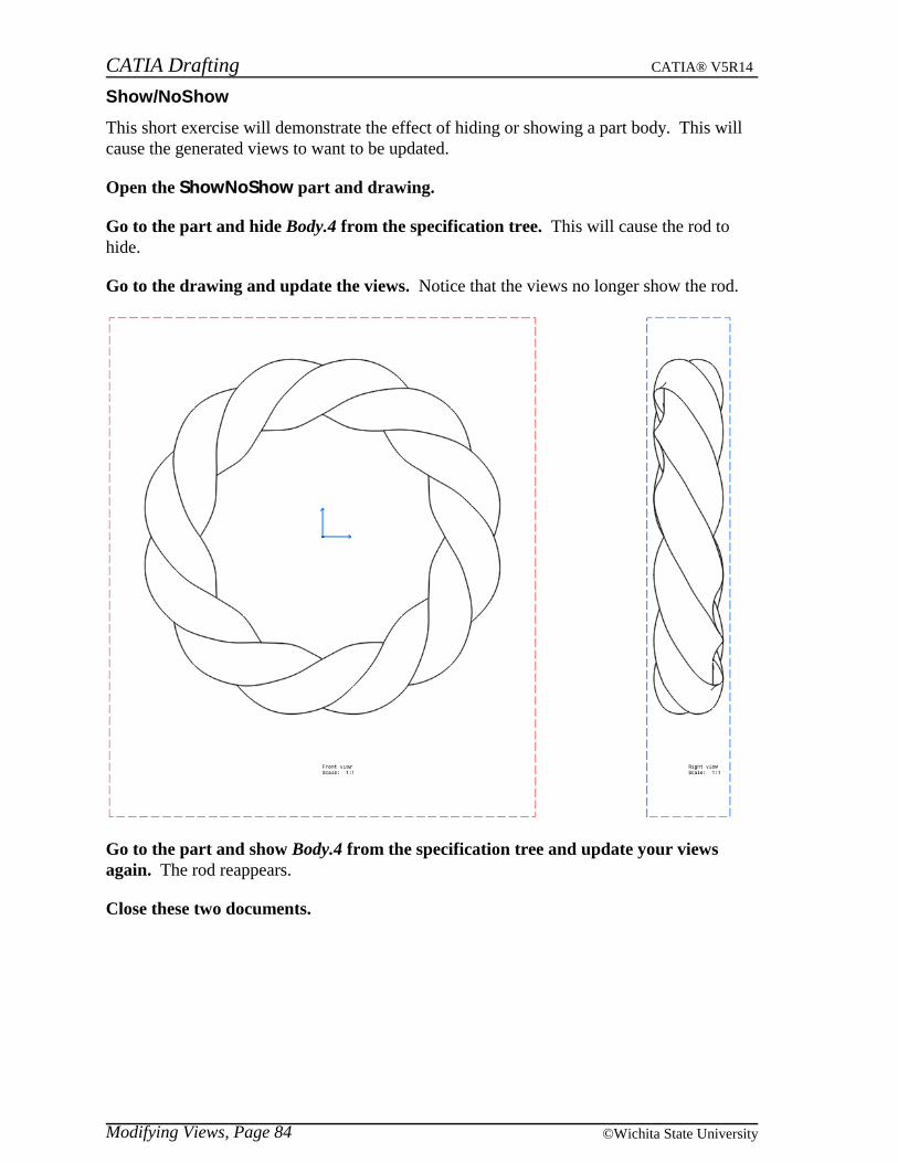
CATIA Drafting CATIA® V5R14
Modifying Views, Page 84 ©Wichita State University
Show/NoShow
This short exercise will demonstrate the effect of hiding or showing a part body. This willcause the generated views to want to be updated.
Open the ShowNoShow part and drawing.
Go to the part and hide Body.4 from the specification tree. This will cause the rod tohide.
Go to the drawing and update the views. Notice that the views no longer show the rod.
Go to the part and show Body.4 from the specification tree and update your viewsagain. The rod reappears.
Close these two documents.
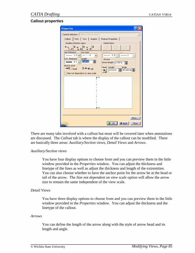
CATIA Drafting CATIA® V5R14
Modifying Views, Page 85© Wichita State University
Callout properties
There are many tabs involved with a callout but most will be covered later when annotationsare discussed. The Callout tab is where the display of the callout can be modified. Thereare basically three areas: Auxiliary/Section views, Detail Views and Arrows.
Auxiliary/Section views
You have four display options to choose from and you can preview them in the littlewindow provided in the Properties window. You can adjust the thickness andlinetype of the lines as well as adjust the thickness and length of the extremities.You can also choose whether to have the anchor point for the arrow be at the head ortail of the arrow. The Size not dependent on view scale option will allow the arrowsize to remain the same independent of the view scale.
Detail Views
You have three display options to choose from and you can preview them in the littlewindow provided in the Properties window. You can adjust the thickness and thelinetype of the callout.
Arrows
You can define the length of the arrow along with the style of arrow head and itslength and angle.
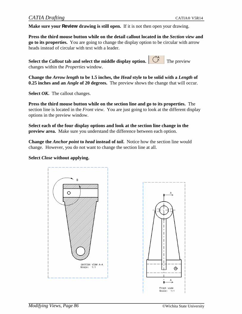
CATIA Drafting CATIA® V5R14
Modifying Views, Page 86 ©Wichita State University
Make sure your Review drawing is still open. If it is not then open your drawing.
Press the third mouse button while on the detail callout located in the Section view andgo to its properties. You are going to change the display option to be circular with arrowheads instead of circular with text with a leader.
Select the Callout tab and select the middle display option. The previewchanges within the Properties window.
Change the Arrow length to be 1.5 inches, the Head style to be solid with a Length of0.25 inches and an Angle of 20 degrees. The preview shows the change that will occur.
Select OK. The callout changes.
Press the third mouse button while on the section line and go to its properties. Thesection line is located in the Front view. You are just going to look at the different displayoptions in the preview window.
Select each of the four display options and look at the section line change in thepreview area. Make sure you understand the difference between each option.
Change the Anchor point to head instead of tail. Notice how the section line wouldchange. However, you do not want to change the section line at all.
Select Close without applying.

CATIA Drafting CATIA® V5R14
Modifying Views, Page 87© Wichita State University
Callout Definition
Besides adjusting the properties of a callout you can also change the definition of a callout.You do this by double selecting on the callout and some new icons will appear.
Double select on the detail callout in the Section view. This will bring up three newicons.
Ends the editing of the profile
Allows you to replace the profile with a new one
Inverts the profile direction (not available for a detail callout)
Select the replace profile icon. This will allow you to define a new profile for thedetail view. The old profile will remain until you have defined the new profile. The ToolsPalette window appears.
Define a circular profile on the right side of the section instead of the left. After youfinish defining the new profile, the old profile disappears.
Select the end profile edition icon. Your detail view automatically updates and thetwo views should appear similar to the diagram shown below.

CATIA Drafting CATIA® V5R14
Modifying Views, Page 88 ©Wichita State University
Double select on the section line. The three icons appear again.
Select the invert profile direction icon. This will reverse the direction of the sectionarrows defining the opposite view.
Select the end profile edition icon. Notice that the section view changes so that the hole isnow on the right side instead of the left. By inverting the section arrows you basicallyreversed the view.
Invert the section arrows back to their original direction and change the profile for thedetail callout to be back at its original location.
Save your drawing but do not close it.

CATIA Drafting CATIA® V5R14
Modifying Views, Page 89© Wichita State University
Unbreak and Unclip
You can unbreak a broken view and unclip a clipped view using these options. You alsohave the capability to remove a breakout but this exercise does not involve a breakout.
Using the third mouse button select on the Clipped view in the specification tree andselect Clipped view object, Unclip. The clip is removed and the entire isometric appears inthe view.
Using the third mouse button select on the bottom Isometric view in the specificationtree and select Isometric view object, Unbreak. The break is removed and the entireisometric appears.
Delete the Clipped view and modify the properties of the bottom Isometric view to showhidden lines.
Move the views around until your drawing looks similar to the one shown below andsave and close your drawing. You will need to delete one of the isometric views.

CATIA Drafting CATIA® V5R14
Modifying Views, Page 90 ©Wichita State University
Modifying Projection Plane
This exercise will show how you can change the plane in which a view is associated. Thisgives you the capability to modify the orientation of the view after you have created it. Allviews that are linked to it will update as well.
Open the View Projection Plane part and drawing.
Using the third mouse button select on the Front view and select on Front view object,Modify Projection Plane. This will allow you to specify a new plane to determine the view.
In the part select the face as shown below.
Go back to the drawing and change the orientation as shown below. You will see theresult from the new projection plane and the blue orientation circle will be available.
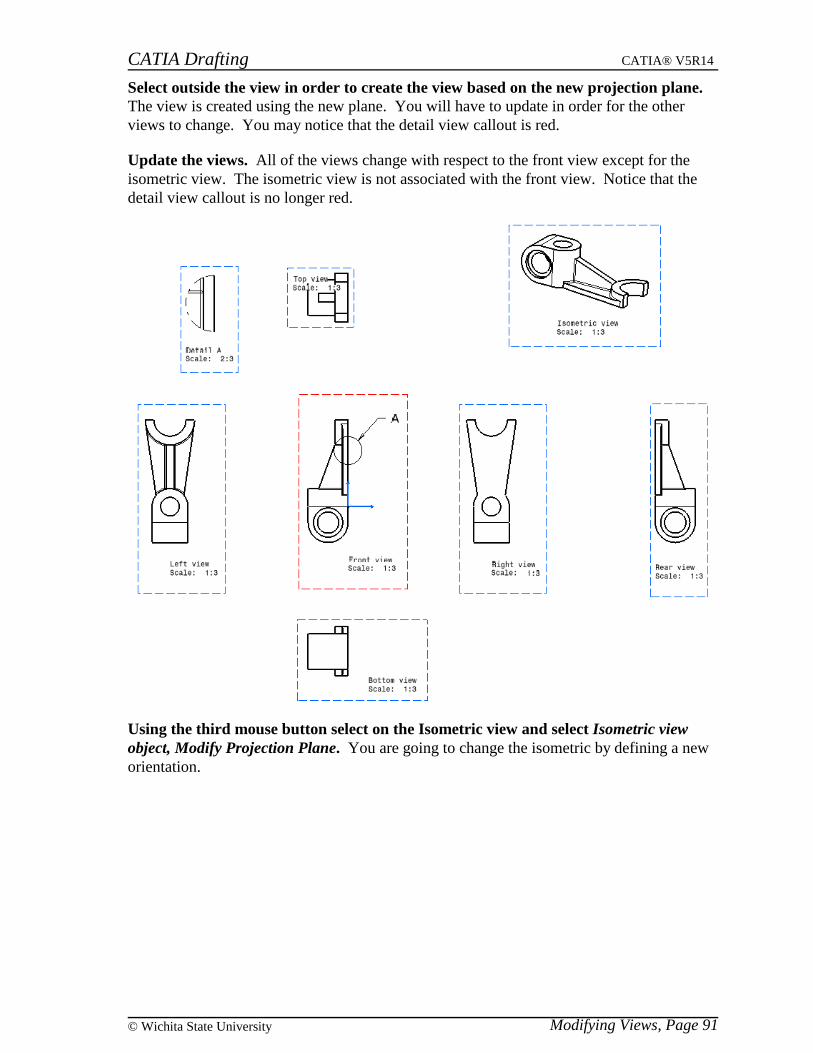
CATIA Drafting CATIA® V5R14
Modifying Views, Page 91© Wichita State University
Select outside the view in order to create the view based on the new projection plane.The view is created using the new plane. You will have to update in order for the otherviews to change. You may notice that the detail view callout is red.
Update the views. All of the views change with respect to the front view except for theisometric view. The isometric view is not associated with the front view. Notice that thedetail view callout is no longer red.
Using the third mouse button select on the Isometric view and select Isometric viewobject, Modify Projection Plane. You are going to change the isometric by defining a neworientation.
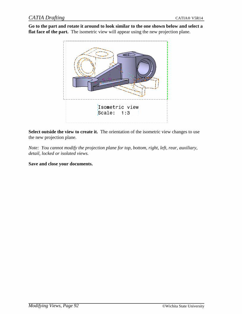
CATIA Drafting CATIA® V5R14
Modifying Views, Page 92 ©Wichita State University
Go to the part and rotate it around to look similar to the one shown below and select aflat face of the part. The isometric view will appear using the new projection plane.
Select outside the view to create it. The orientation of the isometric view changes to usethe new projection plane.
Note: You cannot modify the projection plane for top, bottom, right, left, rear, auxiliary,detail, locked or isolated views.
Save and close your documents.
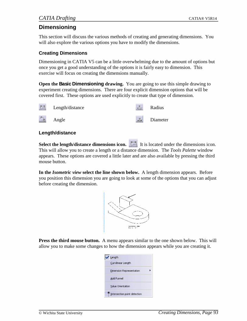
CATIA Drafting CATIA® V5R14
Creating Dimensions, Page 93© Wichita State University
Dimensioning
This section will discuss the various methods of creating and generating dimensions. Youwill also explore the various options you have to modify the dimensions.
Creating Dimensions
Dimensioning in CATIA V5 can be a little overwhelming due to the amount of options butonce you get a good understanding of the options it is fairly easy to dimension. Thisexercise will focus on creating the dimensions manually.
Open the Basic Dimensioning drawing. You are going to use this simple drawing toexperiment creating dimensions. There are four explicit dimension options that will becovered first. These options are used explicitly to create that type of dimension.
Length/distance
Angle
Radius
Diameter
Length/distance
Select the length/distance dimensions icon. It is located under the dimensions icon.This will allow you to create a length or a distance dimension. The Tools Palette windowappears. These options are covered a little later and are also available by pressing the thirdmouse button.
In the Isometric view select the line shown below. A length dimension appears. Beforeyou position this dimension you are going to look at some of the options that you can adjustbefore creating the dimension.
Press the third mouse button. A menu appears similar to the one shown below. This willallow you to make some changes to how the dimension appears while you are creating it.
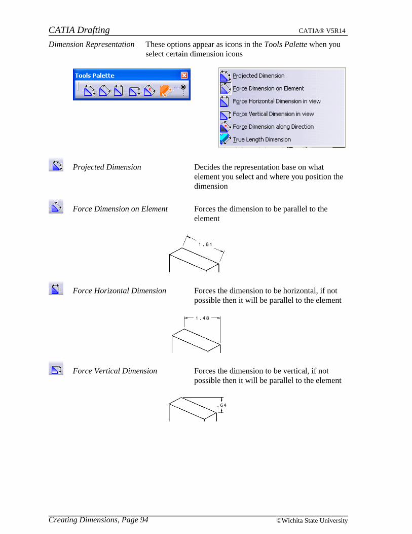
CATIA Drafting CATIA® V5R14
Creating Dimensions, Page 94 ©Wichita State University
Dimension Representation These options appear as icons in the Tools Palette when youselect certain dimension icons
Projected Dimension Decides the representation base on whatelement you select and where you position thedimension
Force Dimension on Element Forces the dimension to be parallel to theelement
Force Horizontal Dimension Forces the dimension to be horizontal, if notpossible then it will be parallel to the element
Force Vertical Dimension Forces the dimension to be vertical, if notpossible then it will be parallel to the element

CATIA Drafting CATIA® V5R14
Creating Dimensions, Page 95© Wichita State University
Force Dimension along Direction Forces the dimension to measure along aspecified direction. You can define thedirection and have it measure along thedirection, normal to the direction or along afixed angle with respect to the view. The sub-icons that appear in the Tools Palette areshown below. You can access these options bypressing the third mouse button again afterchoosing the Force Dimension along Directionoption.
Along a specified direction or at a fixedangle with respect to the direction
Normal to a specified direction
Fixed angle with respect to the view
True Length Dimension Gives the true length of the element, the truelength option generates a purple dimension todistinguish itself as a true length
Measures from an intersection point This option needs to be selected beforedefining the element to dimension in order toselect intersection points of elements. This isnot part of the Dimension Representation.

CATIA Drafting CATIA® V5R14
Creating Dimensions, Page 96 ©Wichita State University
Add Funnel
Height, Angle and Width Refers to the height, width and angle of the funnel
Funnel mode Determines whether the funnel will go out External orgo in Internal
Funnel side Determines whether the funnel affects Both Sides, justthe Left or Bottom, or just the Right or Top
External, Both Sides Internal, Left or Bottom
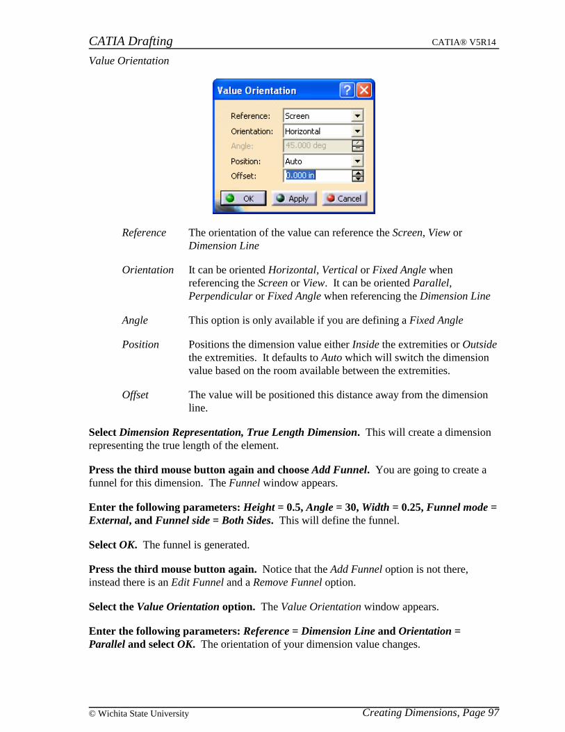
CATIA Drafting CATIA® V5R14
Creating Dimensions, Page 97© Wichita State University
Value Orientation
Reference The orientation of the value can reference the Screen, View orDimension Line
Orientation It can be oriented Horizontal, Vertical or Fixed Angle whenreferencing the Screen or View. It can be oriented Parallel,Perpendicular or Fixed Angle when referencing the Dimension Line
Angle This option is only available if you are defining a Fixed Angle
Position Positions the dimension value either Inside the extremities or Outsidethe extremities. It defaults to Auto which will switch the dimensionvalue based on the room available between the extremities.
Offset The value will be positioned this distance away from the dimensionline.
Select Dimension Representation, True Length Dimension. This will create a dimensionrepresenting the true length of the element.
Press the third mouse button again and choose Add Funnel. You are going to create afunnel for this dimension. The Funnel window appears.
Enter the following parameters: Height = 0.5, Angle = 30, Width = 0.25, Funnel mode =External, and Funnel side = Both Sides. This will define the funnel.
Select OK. The funnel is generated.
Press the third mouse button again. Notice that the Add Funnel option is not there,instead there is an Edit Funnel and a Remove Funnel option.
Select the Value Orientation option. The Value Orientation window appears.
Enter the following parameters: Reference = Dimension Line and Orientation =Parallel and select OK. The orientation of your dimension value changes.
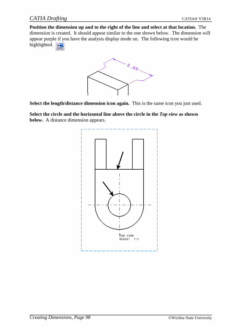
CATIA Drafting CATIA® V5R14
Creating Dimensions, Page 98 ©Wichita State University
Position the dimension up and to the right of the line and select at that location. Thedimension is created. It should appear similar to the one shown below. The dimension willappear purple if you have the analysis display mode on. The following icon would behighlighted.
Select the length/distance dimension icon again. This is the same icon you just used.
Select the circle and the horizontal line above the circle in the Top view as shownbelow. A distance dimension appears.

CATIA Drafting CATIA® V5R14
Creating Dimensions, Page 99© Wichita State University
Press the third mouse button. Two new options appear. Only one will be discussed atthis moment.
Extension Lines Anchor Determines where the extension lines will be based.
Anchor 1 Is some location along the circle
Anchor 2 This is always the center of the circle
Anchor 3 Is some location along the circle
These options would appear if you had selected twocircles. You would have to choose an anchor for eachextension line.
Select Extension Lines Anchor, Anchor 3. In this case it uses a location on the circlewhich is closest to the line.
Specify the location of the dimension as shown below.
CATIA Drafting CATIA® V5R14
Creating Dimensions, Page 100 ©Wichita State University
Select the length/distance dimension icon again.
Select the vertical center line and the leftmost vertical line of the Top view. You aregoing to create a half dimension which will automatically double the value and get rid of theextension line at the center line.
Press the third mouse button. This time you are going to choose the Half dimensionoption.
Select the Half dimension option. This is a toggle, therefore any dimensions that youcreate after this will also be half dimensions until you toggle the option back off.
Specify a location for the dimension. Notice that the value doubled in value and there isonly one extension line. You are now going to undo the dimension.
Select the undo icon in the bottom toolbar until the dimension disappears.
Delete the other dimensions. You can delete them by selecting them and pressing theDelete key.

CATIA Drafting CATIA® V5R14
Creating Dimensions, Page 101© Wichita State University
Angle
Select the angle dimensions icon. It is located under the dimensions orlength/distance dimensions icon. This will create an angle dimension.
Select on the angled line and the top horizontal line in the Right view. Unless you havealready turned the Half dimension off you need to do so now.
Press the third mouse button and select Half dimension. This will toggle the Halfdimension option off.
Press the third mouse button again. Most of these options have already been covered.
Angle Sector Allows you to specify what sector you would like to dimension
Select Angle Sector, Sector 2. The sectors are determined by which element you selectfirst.
Specify the location of the dimension as shown below.

CATIA Drafting CATIA® V5R14
Creating Dimensions, Page 102 ©Wichita State University
Radius
Select the radius dimensions icon. It is located under the dimensions or angledimensions icon. This will allow you to create a radius dimension usually used for partialcircles.
Select the large partial circle in the Top view.
Press the third mouse button. The following options appear. The Extend To Centeroption allows you to have your dimension line extend to the center point of the circle. Note:This option is automatically activated sometimes, especially if you have the dimensionlocated within the circle, you need to move the dimension outside the circle and thenactivate the option.
Select Extend To Center to extend the dimension line to the center of the circle. Thedimension line goes all the way to the center point of the circle.
Specify the location of the dimension as shown below.
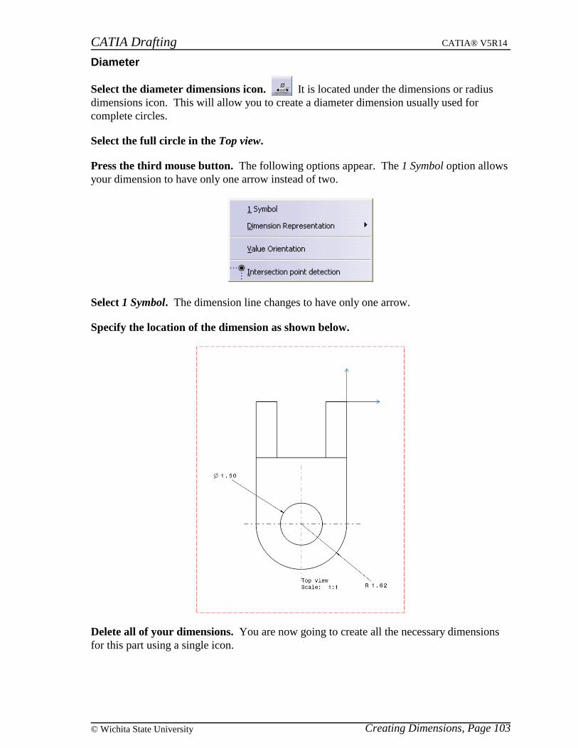
CATIA Drafting CATIA® V5R14
Creating Dimensions, Page 103© Wichita State University
Diameter
Select the diameter dimensions icon. It is located under the dimensions or radiusdimensions icon. This will allow you to create a diameter dimension usually used forcomplete circles.
Select the full circle in the Top view.
Press the third mouse button. The following options appear. The 1 Symbol option allowsyour dimension to have only one arrow instead of two.
Select 1 Symbol. The dimension line changes to have only one arrow.
Specify the location of the dimension as shown below.
Delete all of your dimensions. You are now going to create all the necessary dimensionsfor this part using a single icon.
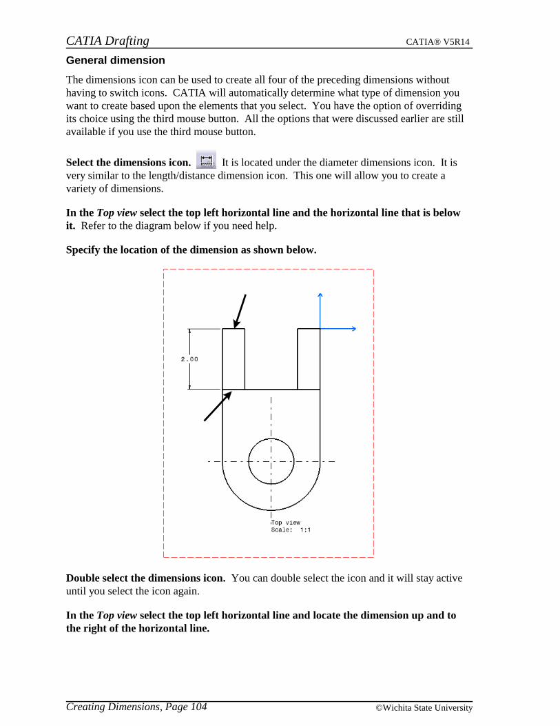
CATIA Drafting CATIA® V5R14
Creating Dimensions, Page 104 ©Wichita State University
General dimension
The dimensions icon can be used to create all four of the preceding dimensions withouthaving to switch icons. CATIA will automatically determine what type of dimension youwant to create based upon the elements that you select. You have the option of overridingits choice using the third mouse button. All the options that were discussed earlier are stillavailable if you use the third mouse button.
Select the dimensions icon. It is located under the diameter dimensions icon. It isvery similar to the length/distance dimension icon. This one will allow you to create avariety of dimensions.
In the Top view select the top left horizontal line and the horizontal line that is belowit. Refer to the diagram below if you need help.
Specify the location of the dimension as shown below.
Double select the dimensions icon. You can double select the icon and it will stay activeuntil you select the icon again.
In the Top view select the top left horizontal line and locate the dimension up and tothe right of the horizontal line.

CATIA Drafting CATIA® V5R14
Creating Dimensions, Page 105© Wichita State University
In the Top view select the large partial circle. It should show a radius dimension.
Press the third mouse button. You have the option of specifying a radius or a diameter.
Select the Radius Center option and locate the dimension down and to the right.
In the Top view select the full circle. You want this dimension to be a diameter.
Press the third mouse button and select the Diameter Center option then locate thedimension down and to the left. You are finished with the Top view. It should appearsimilar to the diagram shown below.
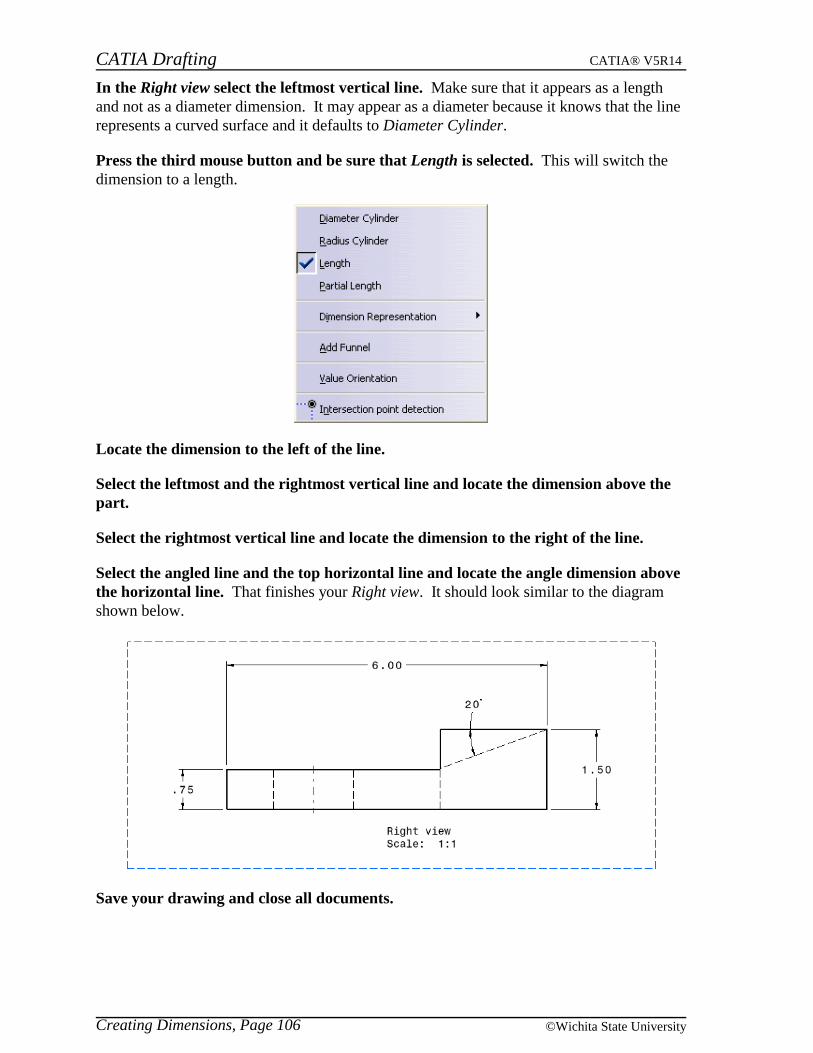
CATIA Drafting CATIA® V5R14
Creating Dimensions, Page 106 ©Wichita State University
In the Right view select the leftmost vertical line. Make sure that it appears as a lengthand not as a diameter dimension. It may appear as a diameter because it knows that the linerepresents a curved surface and it defaults to Diameter Cylinder.
Press the third mouse button and be sure that Length is selected. This will switch thedimension to a length.
Locate the dimension to the left of the line.
Select the leftmost and the rightmost vertical line and locate the dimension above thepart.
Select the rightmost vertical line and locate the dimension to the right of the line.
Select the angled line and the top horizontal line and locate the angle dimension abovethe horizontal line. That finishes your Right view. It should look similar to the diagramshown below.
Save your drawing and close all documents.
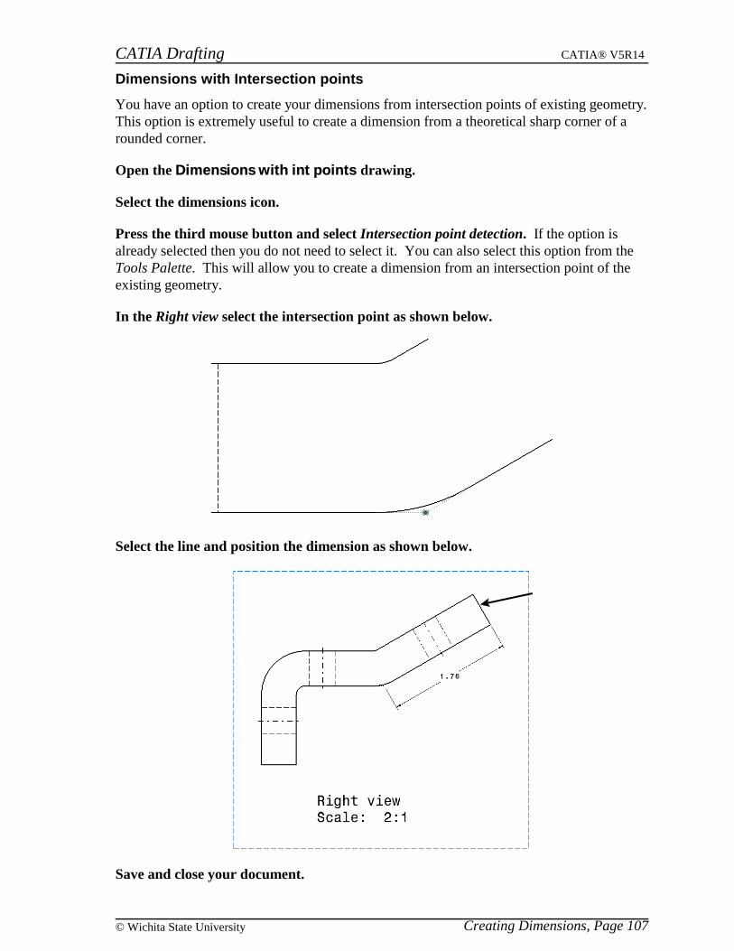
CATIA Drafting CATIA® V5R14
Creating Dimensions, Page 107© Wichita State University
Dimensions with Intersection points
You have an option to create your dimensions from intersection points of existing geometry.This option is extremely useful to create a dimension from a theoretical sharp corner of arounded corner.
Open the Dimensions with int points drawing.
Select the dimensions icon.
Press the third mouse button and select Intersection point detection. If the option isalready selected then you do not need to select it. You can also select this option from theTools Palette. This will allow you to create a dimension from an intersection point of theexisting geometry.
In the Right view select the intersection point as shown below.
Select the line and position the dimension as shown below.
Save and close your document.
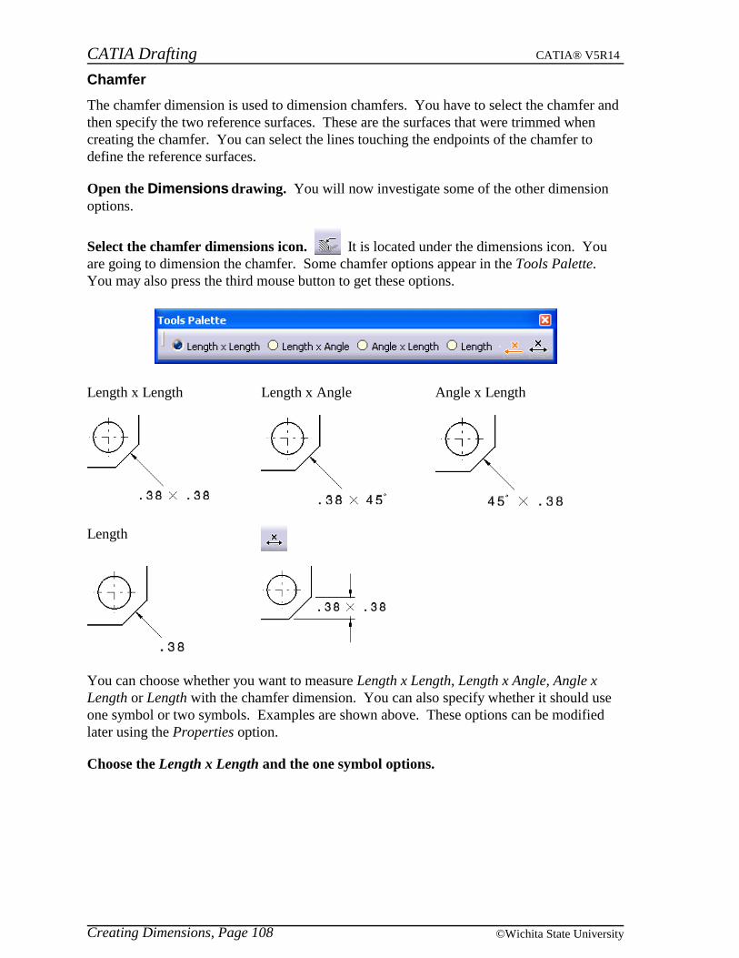
CATIA Drafting CATIA® V5R14
Creating Dimensions, Page 108 ©Wichita State University
Chamfer
The chamfer dimension is used to dimension chamfers. You have to select the chamfer andthen specify the two reference surfaces. These are the surfaces that were trimmed whencreating the chamfer. You can select the lines touching the endpoints of the chamfer todefine the reference surfaces.
Open the Dimensions drawing. You will now investigate some of the other dimensionoptions.
Select the chamfer dimensions icon. It is located under the dimensions icon. Youare going to dimension the chamfer. Some chamfer options appear in the Tools Palette.You may also press the third mouse button to get these options.
Length x Length Length x Angle Angle x Length
Length
You can choose whether you want to measure Length x Length, Length x Angle, Angle xLength or Length with the chamfer dimension. You can also specify whether it should useone symbol or two symbols. Examples are shown above. These options can be modifiedlater using the Properties option.
Choose the Length x Length and the one symbol options.

CATIA Drafting CATIA® V5R14
Creating Dimensions, Page 109© Wichita State University
In the Top view select the chamfer on the right. The chamfer dimension appears. Thiswill occur only if you have the Detect chamfer option turned on in the Tools, Options. If itis not then you must define reference surfaces.
If you want the distance to be measured from a particular side you can either select elementsto define the appropriate reference surfaces or you can make sure that you select the chamferappropriately. The two options shown below appear depending on where you are selectingthe chamfer. Once again, these will only appear if you have the Detect chamfer option on.
1 Shows the element that will be dimensioned
2 Shows the first reference element
3 Shows the second reference element
Locate the dimension as shown below.
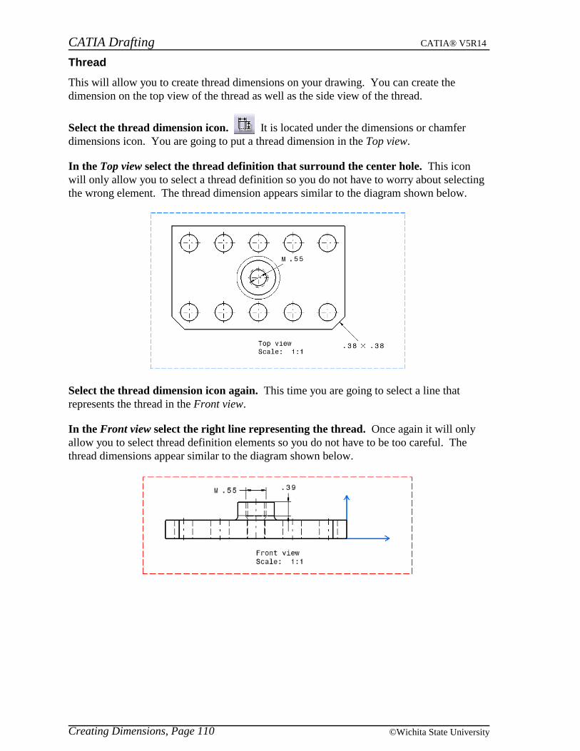
CATIA Drafting CATIA® V5R14
Creating Dimensions, Page 110 ©Wichita State University
Thread
This will allow you to create thread dimensions on your drawing. You can create thedimension on the top view of the thread as well as the side view of the thread.
Select the thread dimension icon. It is located under the dimensions or chamferdimensions icon. You are going to put a thread dimension in the Top view.
In the Top view select the thread definition that surround the center hole. This iconwill only allow you to select a thread definition so you do not have to worry about selectingthe wrong element. The thread dimension appears similar to the diagram shown below.
Select the thread dimension icon again. This time you are going to select a line thatrepresents the thread in the Front view.
In the Front view select the right line representing the thread. Once again it will onlyallow you to select thread definition elements so you do not have to be too careful. Thethread dimensions appear similar to the diagram shown below.
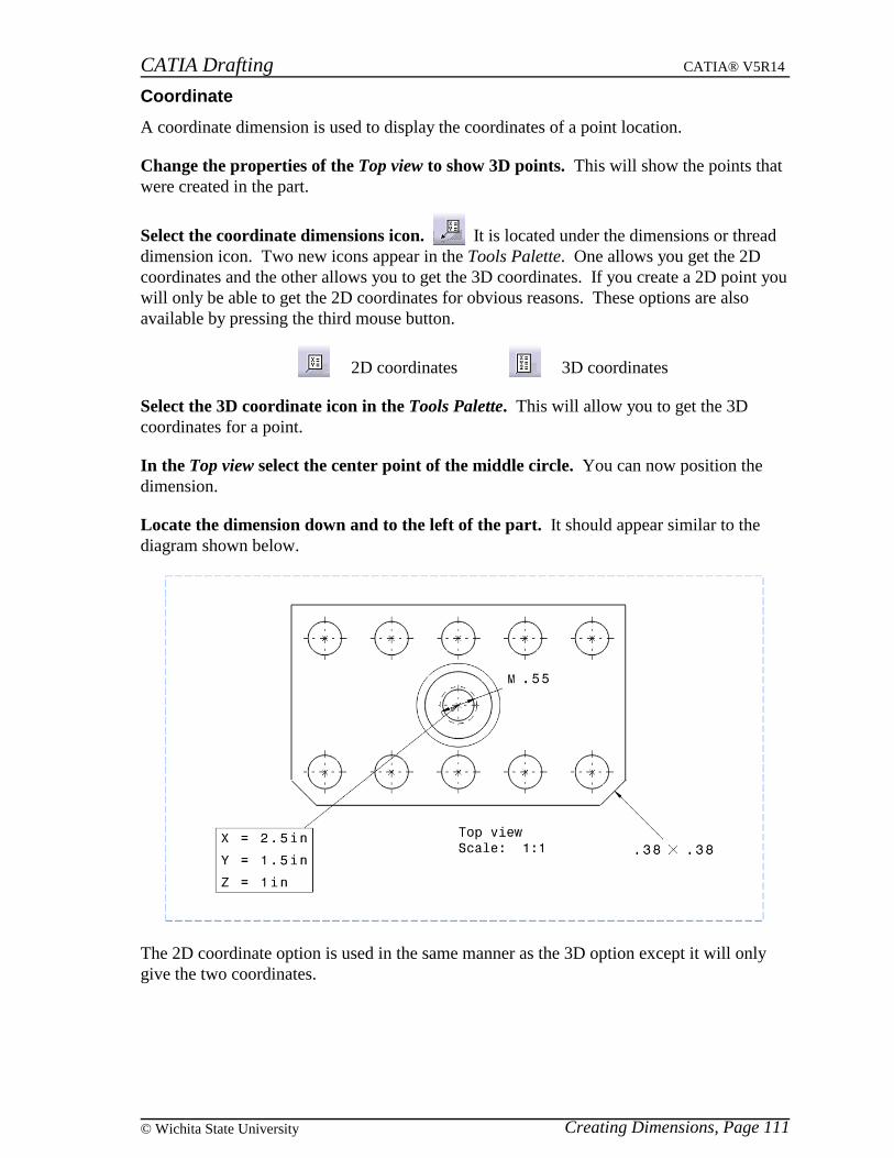
CATIA Drafting CATIA® V5R14
Creating Dimensions, Page 111© Wichita State University
Coordinate
A coordinate dimension is used to display the coordinates of a point location.
Change the properties of the Top view to show 3D points. This will show the points thatwere created in the part.
Select the coordinate dimensions icon. It is located under the dimensions or threaddimension icon. Two new icons appear in the Tools Palette. One allows you get the 2Dcoordinates and the other allows you to get the 3D coordinates. If you create a 2D point youwill only be able to get the 2D coordinates for obvious reasons. These options are alsoavailable by pressing the third mouse button.
2D coordinates 3D coordinates
Select the 3D coordinate icon in the Tools Palette. This will allow you to get the 3Dcoordinates for a point.
In the Top view select the center point of the middle circle. You can now position thedimension.
Locate the dimension down and to the left of the part. It should appear similar to thediagram shown below.
The 2D coordinate option is used in the same manner as the 3D option except it will onlygive the two coordinates.

CATIA Drafting CATIA® V5R14
Creating Dimensions, Page 112 ©Wichita State University
Hole dimension table
You can generate a hole dimension table and position it within a view. You must select allthe holes that you want to include before selecting the icon.
In the Top view select all eleven holes. You can do this by holding down the Ctrl keywhile selecting.
Select the hole dimension table icon. It is located under the dimensions orcoordinate dimensions icon. An Axis System and Table Parameters window appears.
Origin Reference Uses the view origin but you can specify new reference by keying in avalue for X and Y or by selecting an element. You can also changethe Angle and Flip the directions horizontally or vertically. There isalso a toggle to Create Representation of the origin reference or not.
Title Defines the title for the table
Columns Defines the labels that will be used on the holes and in the table. Youcan use letters, numbers or leave them unlabeled. The ... to the rightallows you to specify a starting letter or number for the labeling.Also you can specify whether or not you want the X, Y and Diametervalues.
Titles Defines the titles for each column
Only closed circles Only allows the use of closed circles
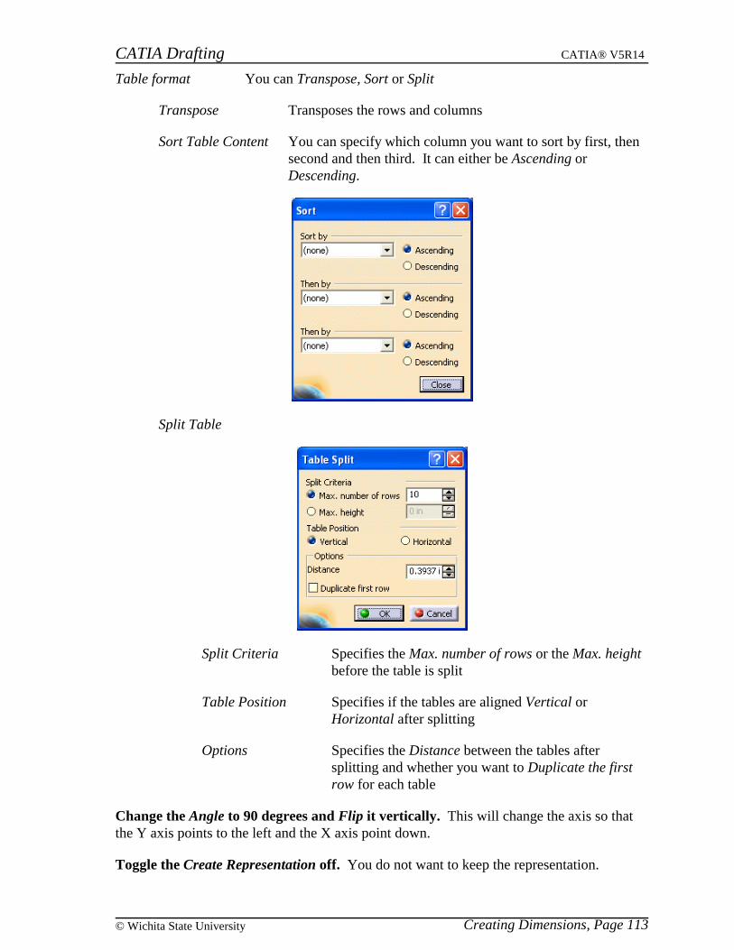
CATIA Drafting CATIA® V5R14
Creating Dimensions, Page 113© Wichita State University
Table format You can Transpose, Sort or Split
Transpose Transposes the rows and columns
Sort Table Content You can specify which column you want to sort by first, thensecond and then third. It can either be Ascending orDescending.
Split Table
Split Criteria Specifies the Max. number of rows or the Max. heightbefore the table is split
Table Position Specifies if the tables are aligned Vertical orHorizontal after splitting
Options Specifies the Distance between the tables aftersplitting and whether you want to Duplicate the firstrow for each table
Change the Angle to 90 degrees and Flip it vertically. This will change the axis so thatthe Y axis points to the left and the X axis point down.
Toggle the Create Representation off. You do not want to keep the representation.
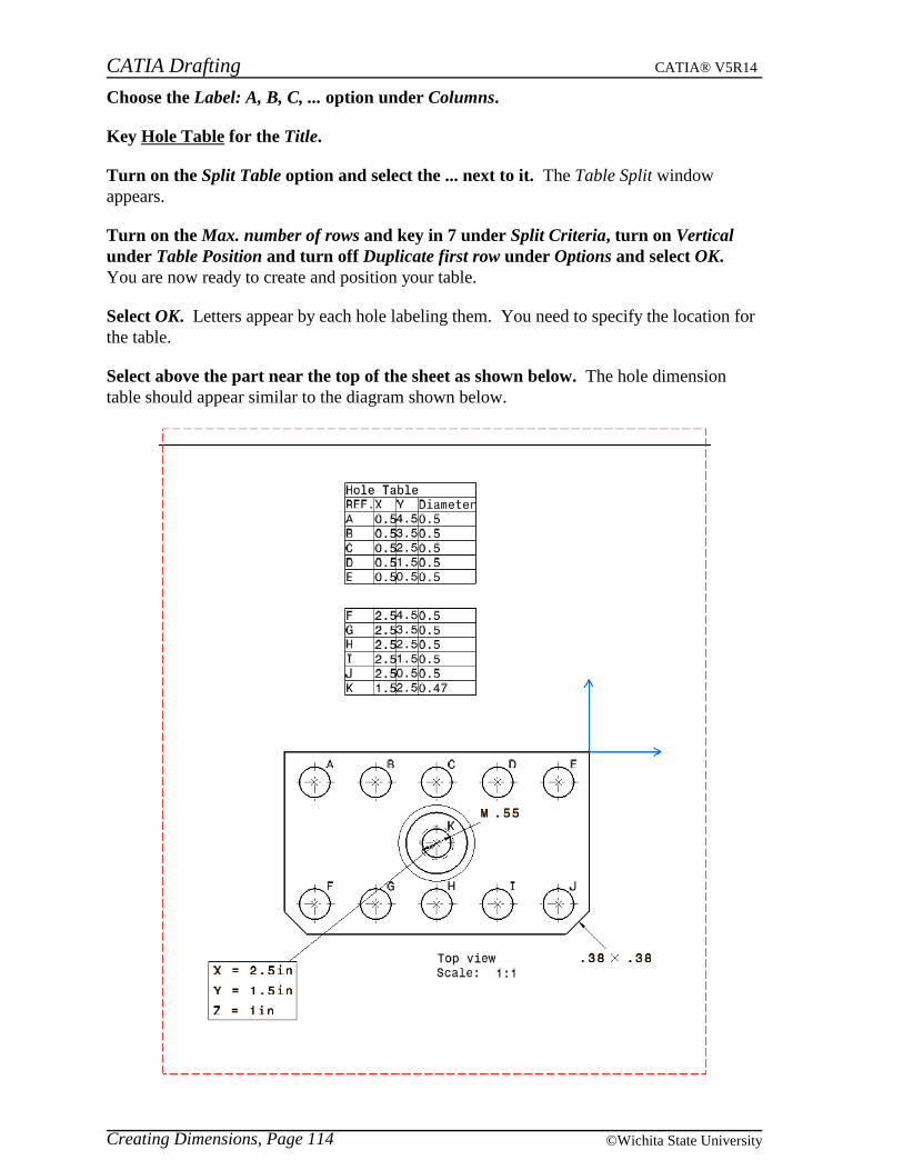
CATIA Drafting CATIA® V5R14
Creating Dimensions, Page 114 ©Wichita State University
Choose the Label: A, B, C, ... option under Columns.
Key Hole Table for the Title.
Turn on the Split Table option and select the ... next to it. The Table Split windowappears.
Turn on the Max. number of rows and key in 7 under Split Criteria, turn on Verticalunder Table Position and turn off Duplicate first row under Options and select OK.You are now ready to create and position your table.
Select OK. Letters appear by each hole labeling them. You need to specify the location forthe table.
Select above the part near the top of the sheet as shown below. The hole dimensiontable should appear similar to the diagram shown below.

CATIA Drafting CATIA® V5R14
Creating Dimensions, Page 115© Wichita State University
Coordinate dimension table
You can also generate a coordinate dimension table and position it within a view. Youshould select all the points that you want to include before selecting the icon.
Select all of the geometry in the Top view. You can do this by using the mouse anddragging a box around the geometry for selection.
Select the coordinate dimension table icon. It is located under the dimensions orhole dimension table icon. An Axis System and Table Parameters window appears. Theoptions are almost identical to the hole dimension table, therefore they will not be discussedhere.
You have the option of using a 3D axis system or the 2D reference axis system. If you usethe 2D reference axis system then it works the same as the hole dimension table. You caneither use the absolute axis system or one that you created in the 3D part.
Change the Axis system to be 3D absolute axis system. This will use that axis to generatethe table.
Key Coordinate Table for the Title and choose the Index: 1, 2, 3, ... option underColumns, make sure the Split Table option is off.
Select OK.
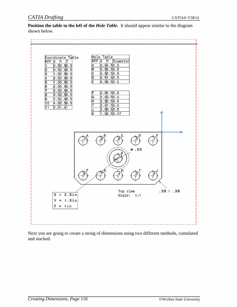
CATIA Drafting CATIA® V5R14
Creating Dimensions, Page 116 ©Wichita State University
Position the table to the left of the Hole Table. It should appear similar to the diagramshown below.
Next you are going to create a string of dimensions using two different methods, cumulatedand stacked.

CATIA Drafting CATIA® V5R14
Creating Dimensions, Page 117© Wichita State University
Chained
The chained dimensions icon allows you to specify an element and then you can continue toselect other elements and it will create a chain of dimensions with each one based off thesecond element of the previous one.
Select the chained dimensions icon. It is located under the dimensions or coordinatedimension table icon. This will allow you to specify an element and then specify a secondelement. Then every selection after that will be based from the previous selection, creatinga string of dimensions.
Turn off the Intersection point detection option.
In the Front view select the leftmost vertical line. You can now continue to select otherelements. The dimensions will not actually be created until you select off an element.
Select the five axis lines one after the other. The dimensions should start appearing.Make sure you select the axis lines and not the hidden lines.
Select off an element. The dimensions are created. It should appear similar to the diagramshown below. You may have to move the view label down in order to see the dimensions.
Select on the .50 dimension and drag it down. Notice that all of the dimensions movewith it. This is because you create a dimension system and you are in dimension systemselection mode. If you wanted to change the properties of the dimensions, you could go toproperties and all of the dimensions would change at the same time.
Turn off the dimension system selection mode icon. This will allow you select eachdimension separately.
Select on the .50 dimension. Notice just that dimension highlights this time. You are nowgoing to undo those dimensions and you are going to create them using the cumulateddimensions icon.
Select undo until the chained dimensions disappear.
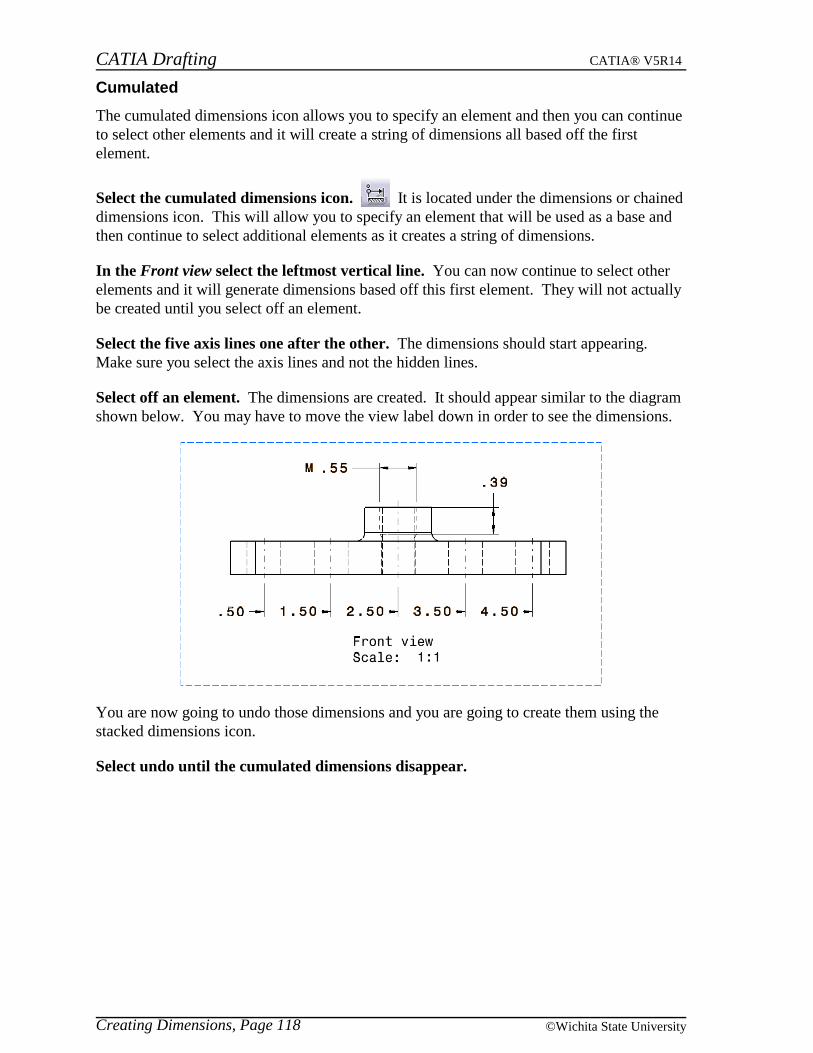
CATIA Drafting CATIA® V5R14
Creating Dimensions, Page 118 ©Wichita State University
Cumulated
The cumulated dimensions icon allows you to specify an element and then you can continueto select other elements and it will create a string of dimensions all based off the firstelement.
Select the cumulated dimensions icon. It is located under the dimensions or chaineddimensions icon. This will allow you to specify an element that will be used as a base andthen continue to select additional elements as it creates a string of dimensions.
In the Front view select the leftmost vertical line. You can now continue to select otherelements and it will generate dimensions based off this first element. They will not actuallybe created until you select off an element.
Select the five axis lines one after the other. The dimensions should start appearing.Make sure you select the axis lines and not the hidden lines.
Select off an element. The dimensions are created. It should appear similar to the diagramshown below. You may have to move the view label down in order to see the dimensions.
You are now going to undo those dimensions and you are going to create them using thestacked dimensions icon.
Select undo until the cumulated dimensions disappear.

CATIA Drafting CATIA® V5R14
Creating Dimensions, Page 119© Wichita State University
Stacked
The stacked dimensions icon allows you to specify an element and then you can continue toselect other elements and it will create a stack of dimensions all based off the first element.This is different from the cumulated style because this will create both extension lines foreach dimension and they will stack outwards instead of being all in one line.
Select the stacked dimensions icon. It is located under the dimensions or cumulateddimensions icon.
In the Front view select the leftmost vertical line. You can now continue to select otherelements and it will generate dimensions based off this first element. They will not actuallybe created until you select off an element.
Select the five axis lines one after the other. The dimensions should start appearing.Make sure you select the axis lines and not the hidden lines.
Select off an element underneath the part. The dimensions are created. It should appearsimilar to the diagram shown below. You may have to move the view label down in orderto see the dimensions.
Notice that the stacked dimensions are spaced apart from one another and they all have bothextension lines.
Save your drawing and close all documents.
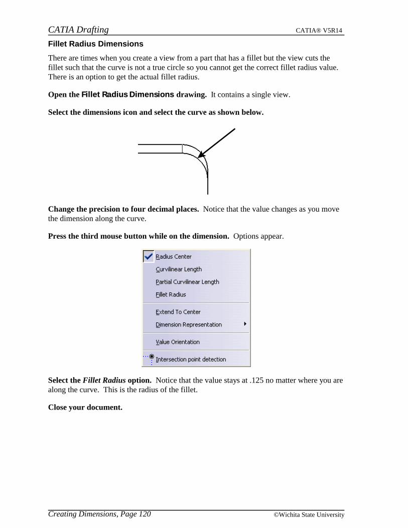
CATIA Drafting CATIA® V5R14
Creating Dimensions, Page 120 ©Wichita State University
Fillet Radius Dimensions
There are times when you create a view from a part that has a fillet but the view cuts thefillet such that the curve is not a true circle so you cannot get the correct fillet radius value.There is an option to get the actual fillet radius.
Open the Fillet Radius Dimensions drawing. It contains a single view.
Select the dimensions icon and select the curve as shown below.
Change the precision to four decimal places. Notice that the value changes as you movethe dimension along the curve.
Press the third mouse button while on the dimension. Options appear.
Select the Fillet Radius option. Notice that the value stays at .125 no matter where you arealong the curve. This is the radius of the fillet.
Close your document.
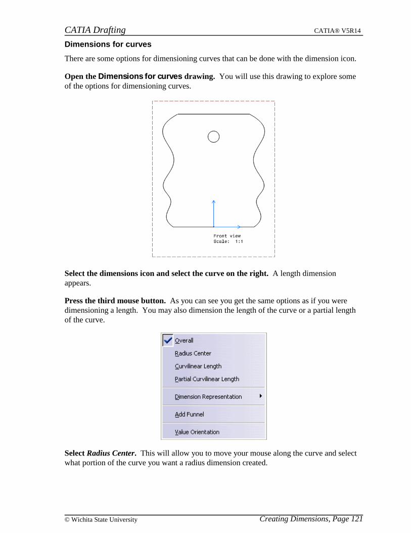
CATIA Drafting CATIA® V5R14
Creating Dimensions, Page 121© Wichita State University
Dimensions for curves
There are some options for dimensioning curves that can be done with the dimension icon.
Open the Dimensions for curves drawing. You will use this drawing to explore someof the options for dimensioning curves.
Select the dimensions icon and select the curve on the right. A length dimensionappears.
Press the third mouse button. As you can see you get the same options as if you weredimensioning a length. You may also dimension the length of the curve or a partial lengthof the curve.
Select Radius Center. This will allow you to move your mouse along the curve and selectwhat portion of the curve you want a radius dimension created.

CATIA Drafting CATIA® V5R14
Creating Dimensions, Page 122 ©Wichita State University
Move your mouse and create a dimension in about the same place as shown below.Your radius value may differ since the radius changes all along the curve.
Select the dimensions icon again and select the top horizontal line and the curve. Adimension appears.
Select the force horizontal dimension in view icon in the Tools Palette. This willmeasure the curve between its highest and lowest point. This option can also be found bypressing the third mouse button and looking under Dimension Representation.
Position the dimension above the curve as shown below.
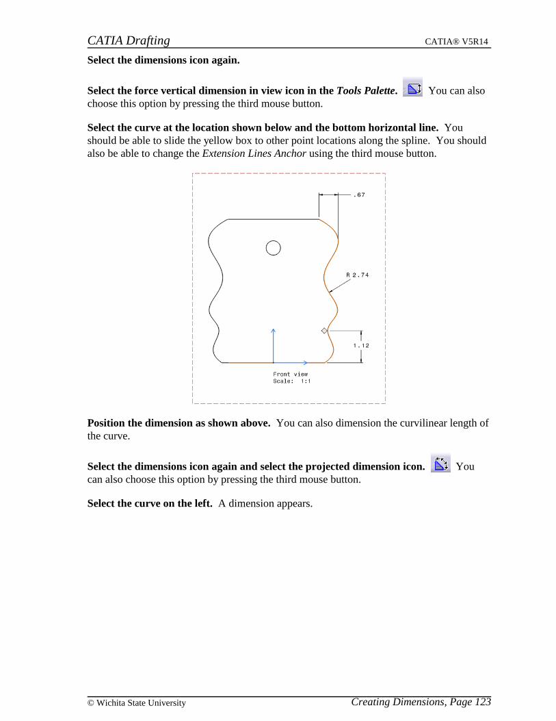
CATIA Drafting CATIA® V5R14
Creating Dimensions, Page 123© Wichita State University
Select the dimensions icon again.
Select the force vertical dimension in view icon in the Tools Palette. You can alsochoose this option by pressing the third mouse button.
Select the curve at the location shown below and the bottom horizontal line. Youshould be able to slide the yellow box to other point locations along the spline. You shouldalso be able to change the Extension Lines Anchor using the third mouse button.
Position the dimension as shown above. You can also dimension the curvilinear length ofthe curve.
Select the dimensions icon again and select the projected dimension icon. Youcan also choose this option by pressing the third mouse button.
Select the curve on the left. A dimension appears.

CATIA Drafting CATIA® V5R14
Creating Dimensions, Page 124 ©Wichita State University
Press the third mouse button and choose Curvilinear Length if not already selected.The following options appear. You will notice that you can also measure a partial length ofthe curve. You have three display options for the dimension.
Offset Parallel Linear

CATIA Drafting CATIA® V5R14
Creating Dimensions, Page 125© Wichita State University
Press the third mouse button and choose Parallel, position the dimension as shownbelow.
Select the dimension icon again and select the curve on the left.
Press the third mouse button and select Partial Curvilinear Length. You will now needto select the two endpoints that you would like to dimension between.
Select the points along the curve as shown and then position the dimension as shown.This will create a dimension along the curve between your selection points. Your value mayvary depending on where you select.
Save your drawing and close all documents.
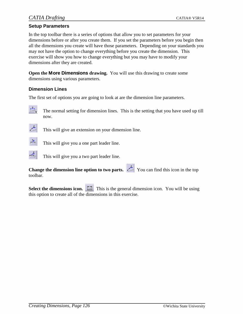
CATIA Drafting CATIA® V5R14
Creating Dimensions, Page 126 ©Wichita State University
Setup Parameters
In the top toolbar there is a series of options that allow you to set parameters for yourdimensions before or after you create them. If you set the parameters before you begin thenall the dimensions you create will have those parameters. Depending on your standards youmay not have the option to change everything before you create the dimension. Thisexercise will show you how to change everything but you may have to modify yourdimensions after they are created.
Open the More Dimensions drawing. You will use this drawing to create somedimensions using various parameters.
Dimension Lines
The first set of options you are going to look at are the dimension line parameters.
The normal setting for dimension lines. This is the setting that you have used up tillnow.
This will give an extension on your dimension line.
This will give you a one part leader line.
This will give you a two part leader line.
Change the dimension line option to two parts. You can find this icon in the toptoolbar.
Select the dimensions icon. This is the general dimension icon. You will be usingthis option to create all of the dimensions in this exercise.
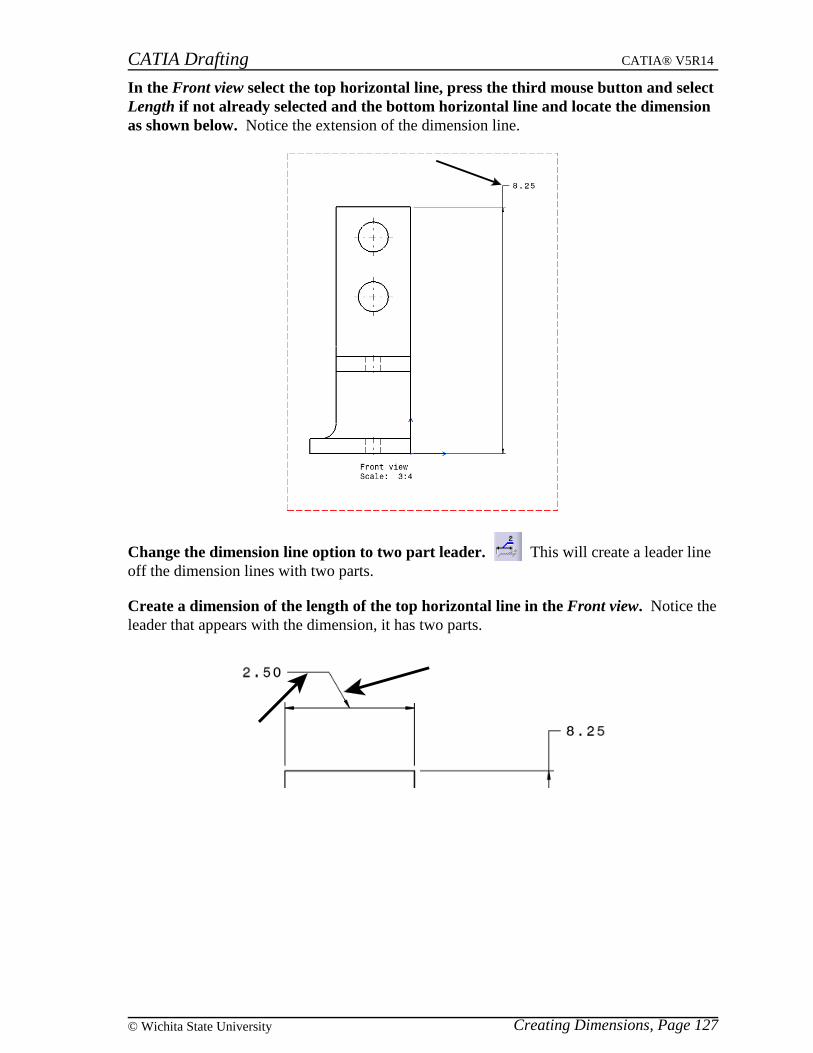
CATIA Drafting CATIA® V5R14
Creating Dimensions, Page 127© Wichita State University
In the Front view select the top horizontal line, press the third mouse button and selectLength if not already selected and the bottom horizontal line and locate the dimensionas shown below. Notice the extension of the dimension line.
Change the dimension line option to two part leader. This will create a leader lineoff the dimension lines with two parts.
Create a dimension of the length of the top horizontal line in the Front view. Notice theleader that appears with the dimension, it has two parts.

CATIA Drafting CATIA® V5R14
Creating Dimensions, Page 128 ©Wichita State University
Change the dimension line option to one part leader. This will create a leader lineoff the dimension lines with just one part.
Create a dimension of the length of the leftmost vertical line in the Front view. Noticethe leader only has one part and not the extra extension.
Change the dimension line option back to regular.

CATIA Drafting CATIA® V5R14
Creating Dimensions, Page 129© Wichita State University
Tolerance
Next to the dimension line options there are two boxes for tolerance. They are describedbelow.
Tolerance Description Tolerance
As you can see there are many types to choose from. In this class you will primarily useTOL_NUM2 and TOL_RES2. TOL_NUM2 is for over/under tolerances and TOL_RES2 isfor limited tolerances. The second box has some predefined values but you can key in yourown.
In the first box select TOL_NUM2 and in the second box select +-0.05. Your nextdimension will have tolerance attached to it.
Create a dimension of the distance between the leftmost vertical line and the rightmostvertical line in the Front view. The tolerance should appear with the dimension. You mayhave to drag the Front view name out of the way.
In the tolerance box key in +0.05/-0.03. You have the option of keying in your tolerancevalue and then it will be added to the list in case you want to use it again within thisdrawing. If you want the tolerance to be the same and use the plus/minus sign then you cankey in the tolerance as follows: +-0.03.

CATIA Drafting CATIA® V5R14
Creating Dimensions, Page 130 ©Wichita State University
Create a dimension of the diameter of the top circle in the Front view.
Change the tolerance description to TOL_RES2 and change the value to +-0.03. Thiswill show the upper and lower limit instead of the + and - tolerance.
Create a dimension of the diameter of the bottom circle in the Front view.
Change the tolerance description to (no tolerance). You will now look at some of thedifferent numerical styles.

CATIA Drafting CATIA® V5R14
Creating Dimensions, Page 131© Wichita State University
Numerical Display
Similar to the tolerance options there are two numerical options. They are described below.
Numerical Display Description Precision
These descriptions represent different units and styles. NUM.DINC will set the unit toinches using the decimal system. NUM.DIMM will set the unit to millimeters. DISTINCHwill set the unit to inches and be followed by a ” to indicate it is in inches. Those areprimarily the ones that will be used in this class. It is important to note that it does notmatter what units you have your model set to using Tools, Options, since the numericaldisplay description determines what units your dimensions are in. The precision boxdetermines how many decimal places to use for the dimension. You can select from one ofthe provided options or you can key in your own precision.
Make sure the numerical display description is set to NUM.DINC and change theprecision to 0.001. You will create another dimension utilizing these parameters.
Create a dimension in the Front view between the vertical center line and the left side.Notice that three decimal places appear on the dimension.
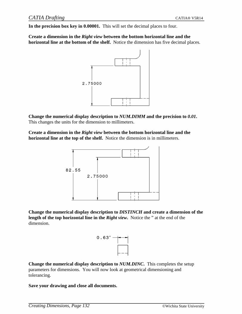
CATIA Drafting CATIA® V5R14
Creating Dimensions, Page 132 ©Wichita State University
In the precision box key in 0.00001. This will set the decimal places to four.
Create a dimension in the Right view between the bottom horizontal line and thehorizontal line at the bottom of the shelf. Notice the dimension has five decimal places.
Change the numerical display description to NUM.DIMM and the precision to 0.01.This changes the units for the dimension to millimeters.
Create a dimension in the Right view between the bottom horizontal line and thehorizontal line at the top of the shelf. Notice the dimension is in millimeters.
Change the numerical display description to DISTINCH and create a dimension of thelength of the top horizontal line in the Right view. Notice the ” at the end of thedimension.
Change the numerical display description to NUM.DINC. This completes the setupparameters for dimensions. You will now look at geometrical dimensioning andtolerancing.
Save your drawing and close all documents.
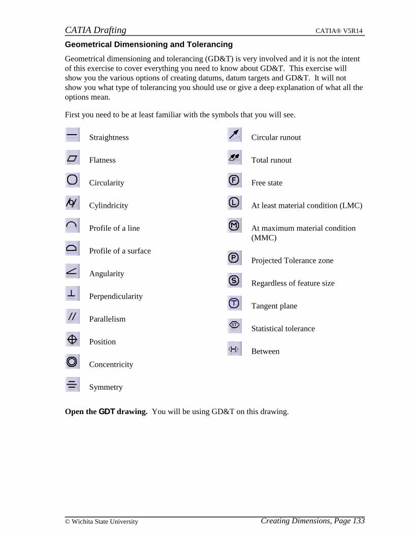
CATIA Drafting CATIA® V5R14
Creating Dimensions, Page 133© Wichita State University
Geometrical Dimensioning and Tolerancing
Geometrical dimensioning and tolerancing (GD&T) is very involved and it is not the intentof this exercise to cover everything you need to know about GD&T. This exercise willshow you the various options of creating datums, datum targets and GD&T. It will notshow you what type of tolerancing you should use or give a deep explanation of what all theoptions mean.
First you need to be at least familiar with the symbols that you will see.
Straightness
Flatness
Circularity
Cylindricity
Profile of a line
Profile of a surface
Angularity
Perpendicularity
Parallelism
Position
Concentricity
Symmetry
Circular runout
Total runout
Free state
At least material condition (LMC)
At maximum material condition(MMC)
Projected Tolerance zone
Regardless of feature size
Tangent plane
Statistical tolerance
Between
Open the GDT drawing. You will be using GD&T on this drawing.
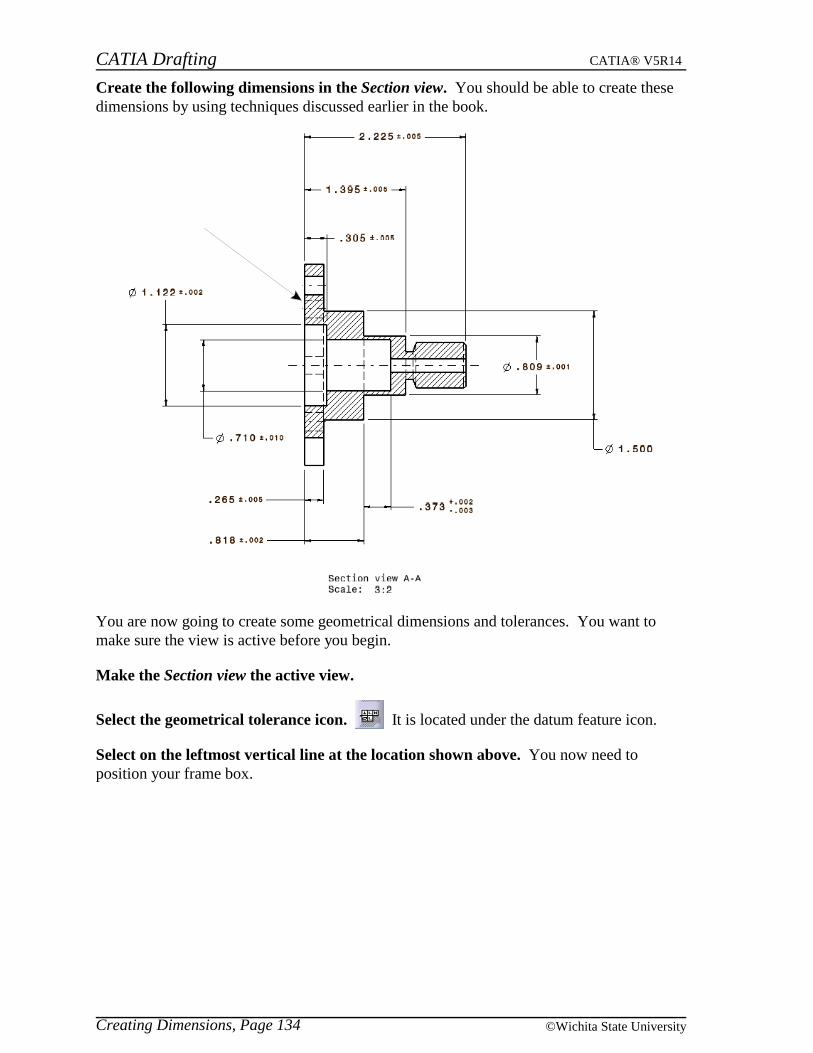
CATIA Drafting CATIA® V5R14
Creating Dimensions, Page 134 ©Wichita State University
Create the following dimensions in the Section view. You should be able to create thesedimensions by using techniques discussed earlier in the book.
You are now going to create some geometrical dimensions and tolerances. You want tomake sure the view is active before you begin.
Make the Section view the active view.
Select the geometrical tolerance icon. It is located under the datum feature icon.
Select on the leftmost vertical line at the location shown above. You now need toposition your frame box.
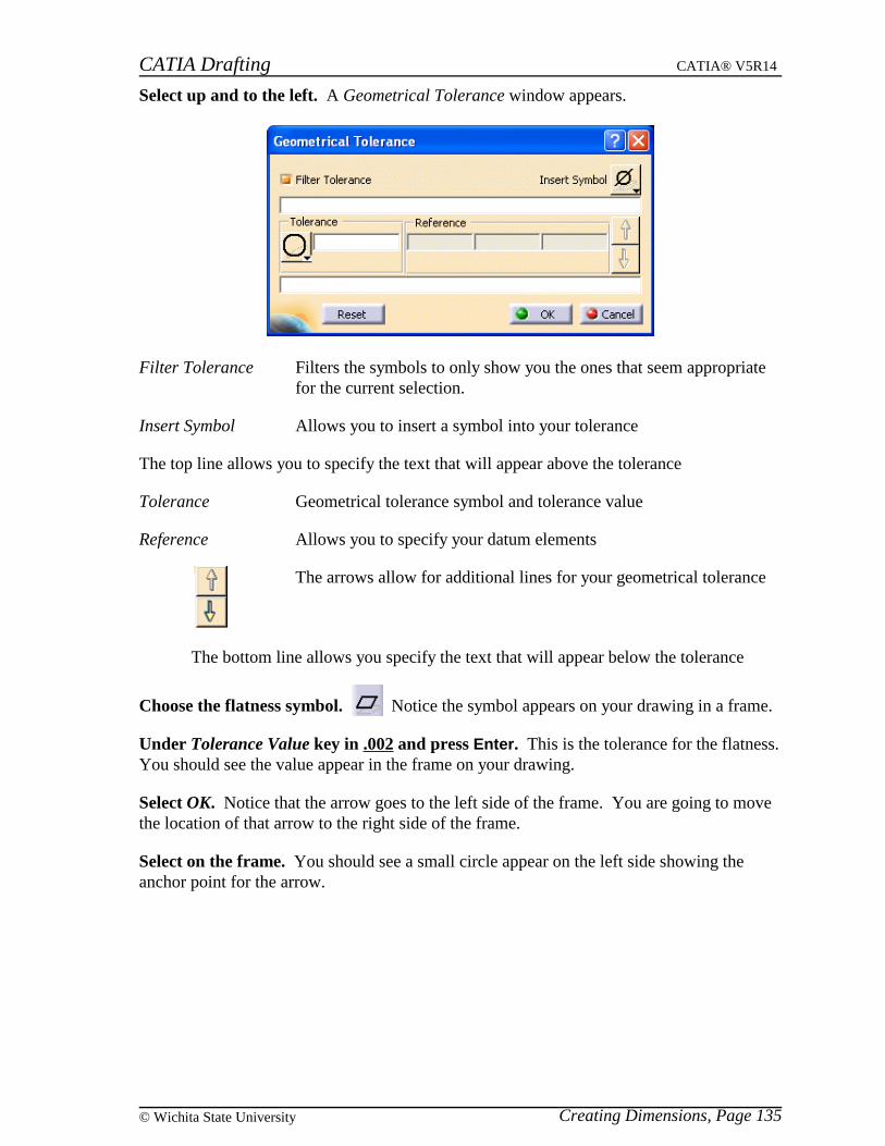
CATIA Drafting CATIA® V5R14
Creating Dimensions, Page 135© Wichita State University
Select up and to the left. A Geometrical Tolerance window appears.
Filter Tolerance Filters the symbols to only show you the ones that seem appropriatefor the current selection.
Insert Symbol Allows you to insert a symbol into your tolerance
The top line allows you to specify the text that will appear above the tolerance
Tolerance Geometrical tolerance symbol and tolerance value
Reference Allows you to specify your datum elements
The arrows allow for additional lines for your geometrical tolerance
The bottom line allows you specify the text that will appear below the tolerance
Choose the flatness symbol. Notice the symbol appears on your drawing in a frame.
Under Tolerance Value key in .002 and press Enter. This is the tolerance for the flatness.You should see the value appear in the frame on your drawing.
Select OK. Notice that the arrow goes to the left side of the frame. You are going to movethe location of that arrow to the right side of the frame.
Select on the frame. You should see a small circle appear on the left side showing theanchor point for the arrow.
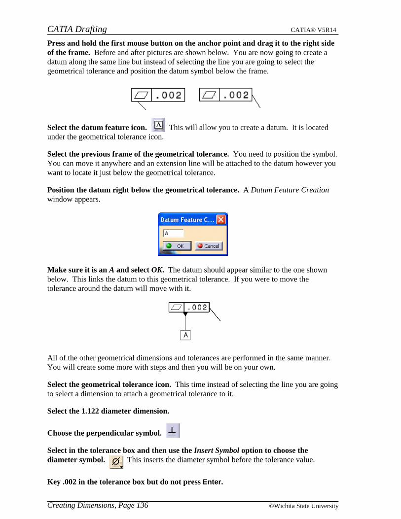
CATIA Drafting CATIA® V5R14
Creating Dimensions, Page 136 ©Wichita State University
Press and hold the first mouse button on the anchor point and drag it to the right sideof the frame. Before and after pictures are shown below. You are now going to create adatum along the same line but instead of selecting the line you are going to select thegeometrical tolerance and position the datum symbol below the frame.
Select the datum feature icon. This will allow you to create a datum. It is locatedunder the geometrical tolerance icon.
Select the previous frame of the geometrical tolerance. You need to position the symbol.You can move it anywhere and an extension line will be attached to the datum however youwant to locate it just below the geometrical tolerance.
Position the datum right below the geometrical tolerance. A Datum Feature Creationwindow appears.
Make sure it is an A and select OK. The datum should appear similar to the one shownbelow. This links the datum to this geometrical tolerance. If you were to move thetolerance around the datum will move with it.
All of the other geometrical dimensions and tolerances are performed in the same manner.You will create some more with steps and then you will be on your own.
Select the geometrical tolerance icon. This time instead of selecting the line you are goingto select a dimension to attach a geometrical tolerance to it.
Select the 1.122 diameter dimension.
Choose the perpendicular symbol.
Select in the tolerance box and then use the Insert Symbol option to choose thediameter symbol. This inserts the diameter symbol before the tolerance value.
Key .002 in the tolerance box but do not press Enter.
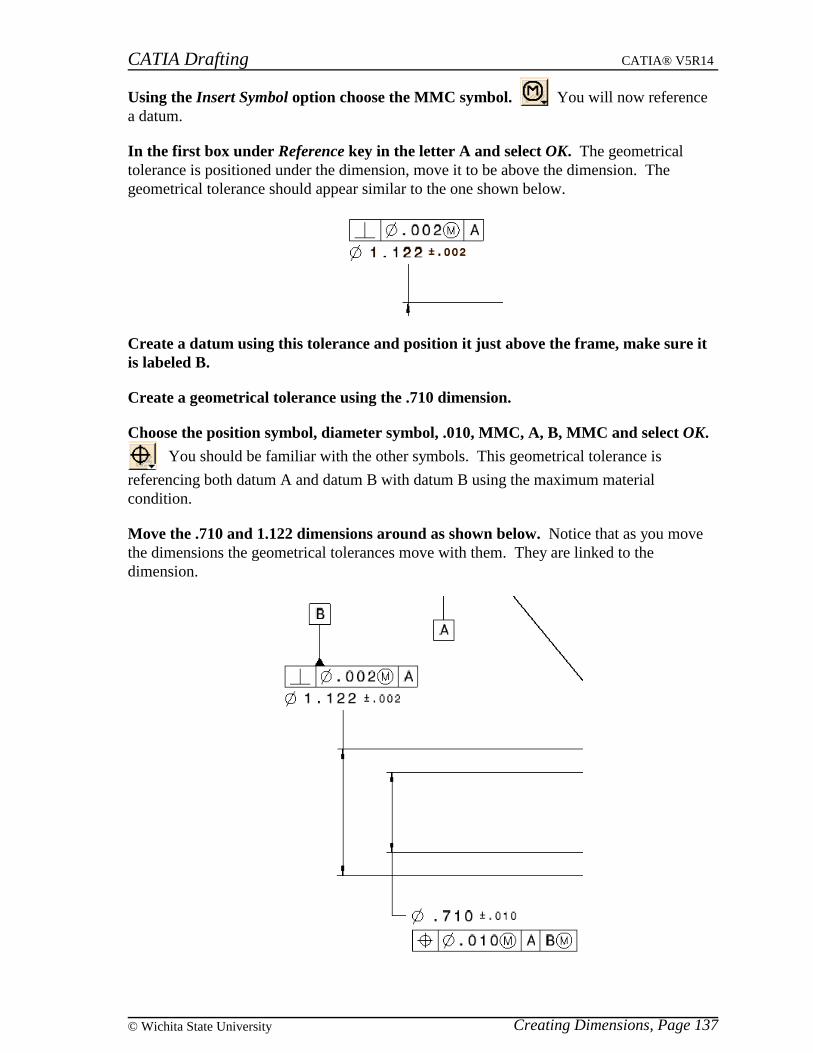
CATIA Drafting CATIA® V5R14
Creating Dimensions, Page 137© Wichita State University
Using the Insert Symbol option choose the MMC symbol. You will now referencea datum.
In the first box under Reference key in the letter A and select OK. The geometricaltolerance is positioned under the dimension, move it to be above the dimension. Thegeometrical tolerance should appear similar to the one shown below.
Create a datum using this tolerance and position it just above the frame, make sure itis labeled B.
Create a geometrical tolerance using the .710 dimension.
Choose the position symbol, diameter symbol, .010, MMC, A, B, MMC and select OK.
You should be familiar with the other symbols. This geometrical tolerance is
referencing both datum A and datum B with datum B using the maximum materialcondition.
Move the .710 and 1.122 dimensions around as shown below. Notice that as you movethe dimensions the geometrical tolerances move with them. They are linked to thedimension.
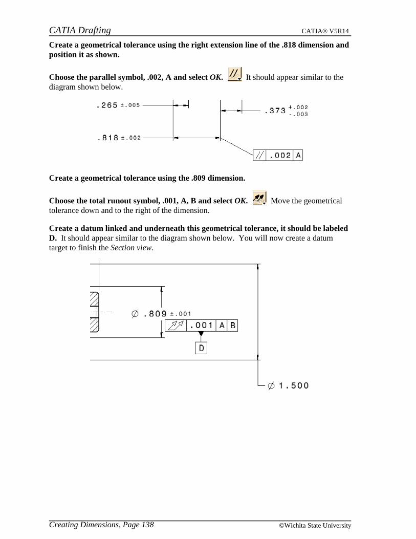
CATIA Drafting CATIA® V5R14
Creating Dimensions, Page 138 ©Wichita State University
Create a geometrical tolerance using the right extension line of the .818 dimension andposition it as shown.
Choose the parallel symbol, .002, A and select OK. It should appear similar to thediagram shown below.
Create a geometrical tolerance using the .809 dimension.
Choose the total runout symbol, .001, A, B and select OK. Move the geometricaltolerance down and to the right of the dimension.
Create a datum linked and underneath this geometrical tolerance, it should be labeledD. It should appear similar to the diagram shown below. You will now create a datumtarget to finish the Section view.
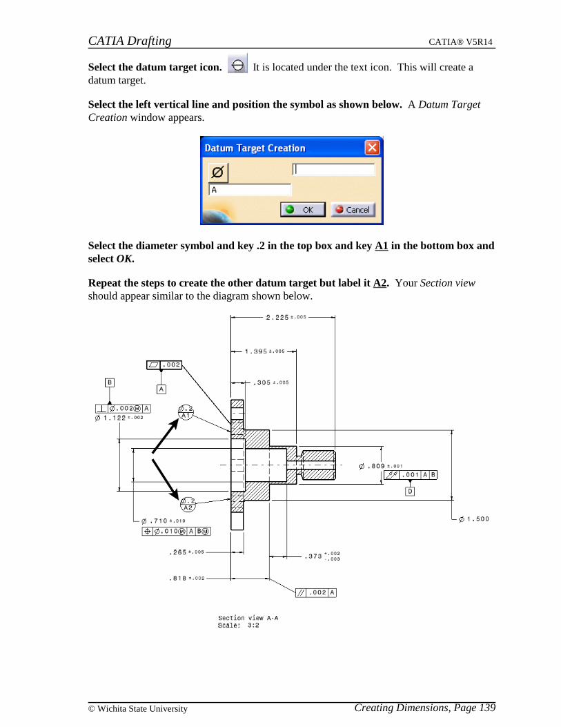
CATIA Drafting CATIA® V5R14
Creating Dimensions, Page 139© Wichita State University
Select the datum target icon. It is located under the text icon. This will create adatum target.
Select the left vertical line and position the symbol as shown below. A Datum TargetCreation window appears.
Select the diameter symbol and key .2 in the top box and key A1 in the bottom box andselect OK.
Repeat the steps to create the other datum target but label it A2. Your Section viewshould appear similar to the diagram shown below.
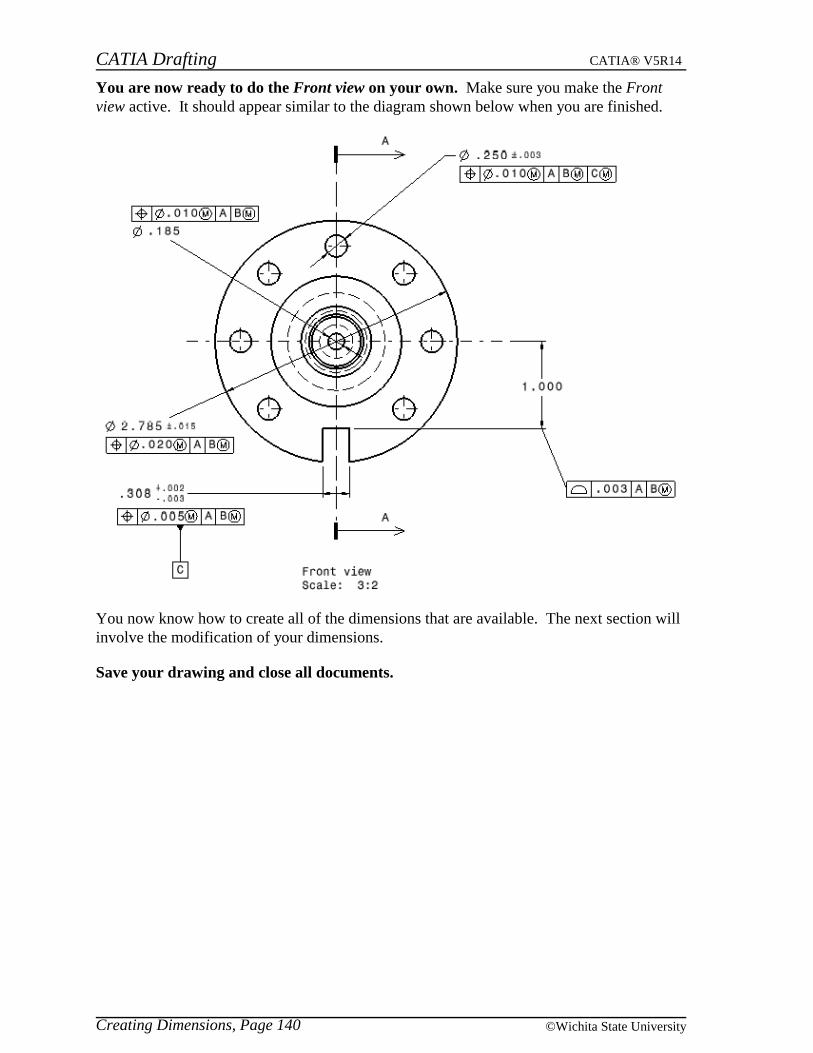
CATIA Drafting CATIA® V5R14
Creating Dimensions, Page 140 ©Wichita State University
You are now ready to do the Front view on your own. Make sure you make the Frontview active. It should appear similar to the diagram shown below when you are finished.
You now know how to create all of the dimensions that are available. The next section willinvolve the modification of your dimensions.
Save your drawing and close all documents.

CATIA Drafting CATIA® V5R14
Modifying Dimensions, Page 141© Wichita State University
Modifying Dimensions
There a lot of ways you can modify your dimensions. One method is to use the options inthe top toolbar. Up until now you have used those options to set the parameters fordimensions you were getting ready to create. You can also turn on some options under thepull down menu Tools, Options, Mechanical Design, Drafting, Manipulators. Anotheroption is to change the properties of the dimension using the third mouse button. All ofthese ways will be explored in this exercise.
Open the GDTfinished drawing. This should be almost identical to your GDT drawingthat you just saved. However, it is probably better to use this one so that all of thedimensions are setup as expected for the exercise. The Section view should be the activeview.
Top Toolbar
The first method of modifying dimensions that you will explore will involve the top toolbar.
Select the 2.225 dimension at the top of the Section view. If you look at the top toolbaryou should notice that the parameters have changed based on what the dimension hasassigned to it. You can modify any of the parameters in the same manner as you set themearlier. The difference is that this time it will only affect the selected dimension.
Change the tolerance from +-0.005 to +0.003/-0.005 and press Enter. The tolerance onthe dimension changes.
Change the precision from 0.001 to 0.0001 and press Enter. Notice the number ofdecimal places changes on the dimension.
Select off the dimension on the sheet. Notice that the top toolbar reverts back to thesettings it had before selecting that dimension. You can also change more than onedimension at a time.
Select the 2.2250 and the 1.395 dimension. You will have to use the Ctrl key to selectboth dimensions at the same time.
Change the tolerance to +-0.003 and change the precision to 0.001. Notice that bothdimensions change to that tolerance and to that number of decimal places. Select off thedimensions on the sheet.
Select the 2.225 dimension and change the dimension line style to two part leader.The dimension changes to have a leader with two parts.
Change the numerical display description to DISTINCH. The dimension appears with ”representing inches.
Change the tolerance description to TOL_RES2. The dimension changes to a limiteddimension.
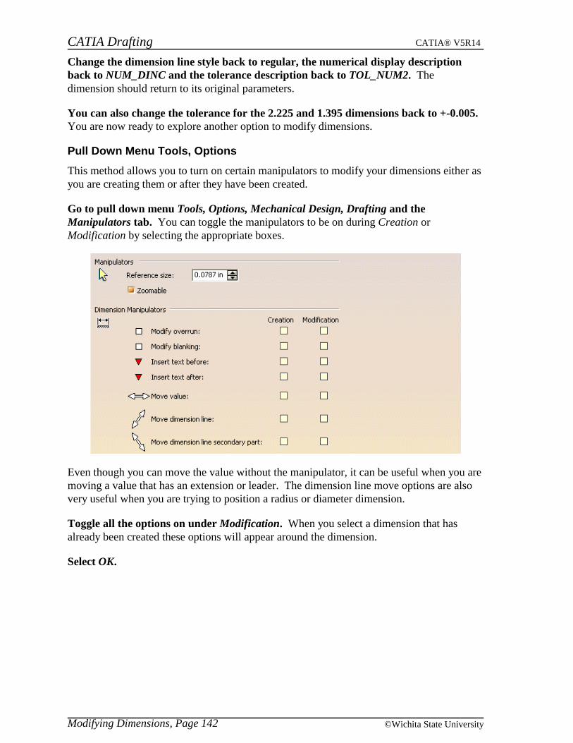
CATIA Drafting CATIA® V5R14
Modifying Dimensions, Page 142 ©Wichita State University
Change the dimension line style back to regular, the numerical display descriptionback to NUM_DINC and the tolerance description back to TOL_NUM2. Thedimension should return to its original parameters.
You can also change the tolerance for the 2.225 and 1.395 dimensions back to +-0.005.You are now ready to explore another option to modify dimensions.
Pull Down Menu Tools, Options
This method allows you to turn on certain manipulators to modify your dimensions either asyou are creating them or after they have been created.
Go to pull down menu Tools, Options, Mechanical Design, Drafting and theManipulators tab. You can toggle the manipulators to be on during Creation orModification by selecting the appropriate boxes.
Even though you can move the value without the manipulator, it can be useful when you aremoving a value that has an extension or leader. The dimension line move options are alsovery useful when you are trying to position a radius or diameter dimension.
Toggle all the options on under Modification. When you select a dimension that hasalready been created these options will appear around the dimension.
Select OK.

CATIA Drafting CATIA® V5R14
Modifying Dimensions, Page 143© Wichita State University
Select on the 2.225 dimension. It should appear similar to the diagram shown below.
Select on the right red triangle. The Insert Text After window appears.
Enter TYP and select OK. Notice the text appears after the dimension.
Select on the left red triangle. The Insert Text Before window appears.
Enter 2X and select OK. Notice the text appears before the dimension.
Press and hold the first mouse button on the white box on the top of the left extensionline. This will allow you to adjust the overrun of your dimension.
Drag the box up by moving the mouse. The overrun of the extension lines extend.
Drag the box down to an appropriate distance and let go. You can see how easy it is toadjust the overrun. The blanking is just as easy.

CATIA Drafting CATIA® V5R14
Modifying Dimensions, Page 144 ©Wichita State University
Drag the white box at the bottom of the right extension line up adjusting the blanking.
Drag the box down to an appropriate distance and let go. With the manipulators turnedon it is very easy to modify your dimension. You can also turn these manipulators onduring creation so you make these changes as you create a dimension.
You should notice that both extension lines get adjusted when you use the manipulators tochange the blanking or overrun. If you only want to adjust one of the extension lines thenyou can hold down the Ctrl key and select the box. This will only adjust the extension lineselected. You also have the option of double selecting on the box and keying in a distancethat you want either for both extension lines or just the one.
Delete the text before and after the 2.225 dimension. You can do this by selecting on theappropriate red triangle and removing the text and select OK.
Select off the dimension on the sheet. This releases the dimension. You can also modifya geometrical tolerance by double selecting on the frame.
Geometrical Tolerance
Double select on the parallel geometric tolerance located at the bottom of the Sectionview. The Geometrical Tolerance window appears just like it does when you create ageometrical tolerance. You can make changes and then select OK when done. Do not makeany changes at this time.
Select Cancel. Now you will look at the properties of a dimension.
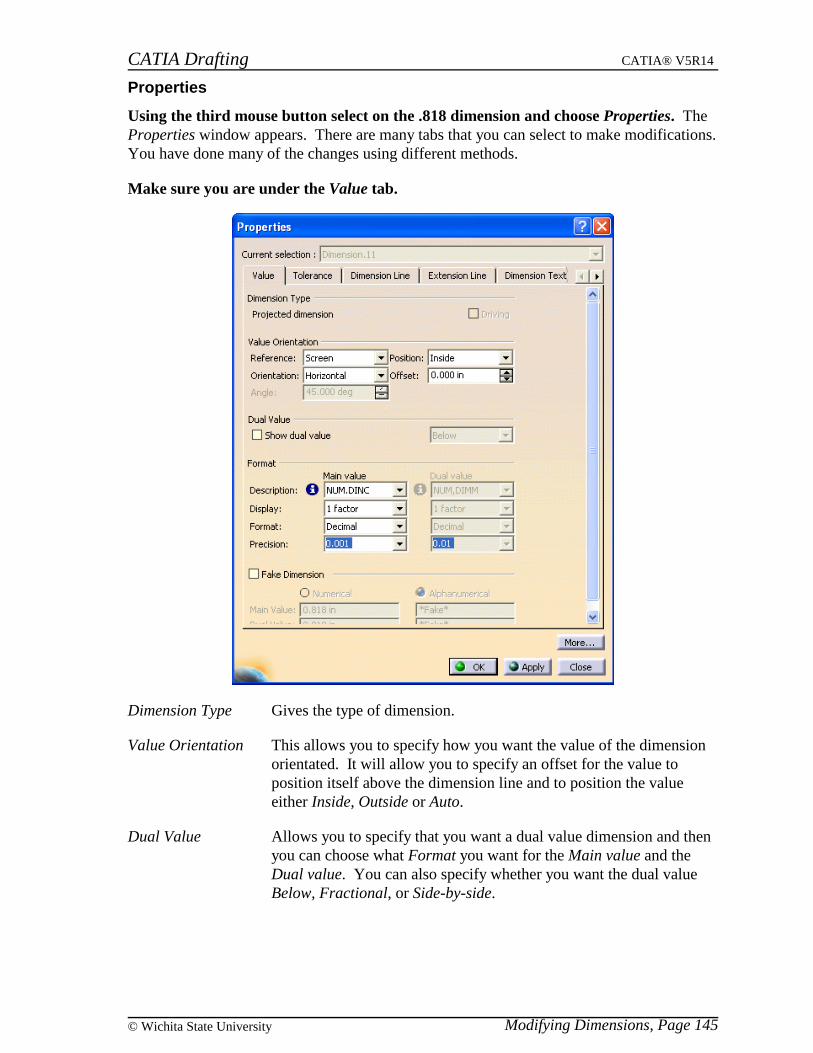
CATIA Drafting CATIA® V5R14
Modifying Dimensions, Page 145© Wichita State University
Properties
Using the third mouse button select on the .818 dimension and choose Properties. TheProperties window appears. There are many tabs that you can select to make modifications.You have done many of the changes using different methods.
Make sure you are under the Value tab.
Dimension Type Gives the type of dimension.
Value Orientation This allows you to specify how you want the value of the dimensionorientated. It will allow you to specify an offset for the value toposition itself above the dimension line and to position the valueeither Inside, Outside or Auto.
Dual Value Allows you to specify that you want a dual value dimension and thenyou can choose what Format you want for the Main value and theDual value. You can also specify whether you want the dual valueBelow, Fractional, or Side-by-side.

CATIA Drafting CATIA® V5R14
Modifying Dimensions, Page 146 ©Wichita State University
Format Allows you to change the numerical display description andprecision. You can also change whether you want the dimension tobe Decimal or Fractional.
Fake Dimension This option is located down in the window. You can turn on theoption to make the dimension fake and then you can specify aNumerical value or a Alphanumerical value.
You are already familiar with most of these options except for the Dual Value and FakeDimension.
Toggle the Show dual value mode on. This will allow you to specify a format for the Dualvalue.
Change the position of the dual value to be Below and the Description to beNUM.DIMM, Format to be Decimal and Precision to be 0.01. Make sure the window ispositioned so that you can see how the dimension looks as you make changes.
Select Apply. You should notice that the dimension has a value in millimeters locatedbelow the original value.
Toggle the Show dual value mode off.
Toggle the Fake Dimension mode on. This will allow you to specify whether you want touse a Numerical or Alphanumerical value as the fake dimension.
Select the Numerical option and change the Main Value to .500 and select Apply.Notice that the dimension value changes to the fake value.
Toggle the Fake Dimension mode off and select Apply. The dimension returns to normal.
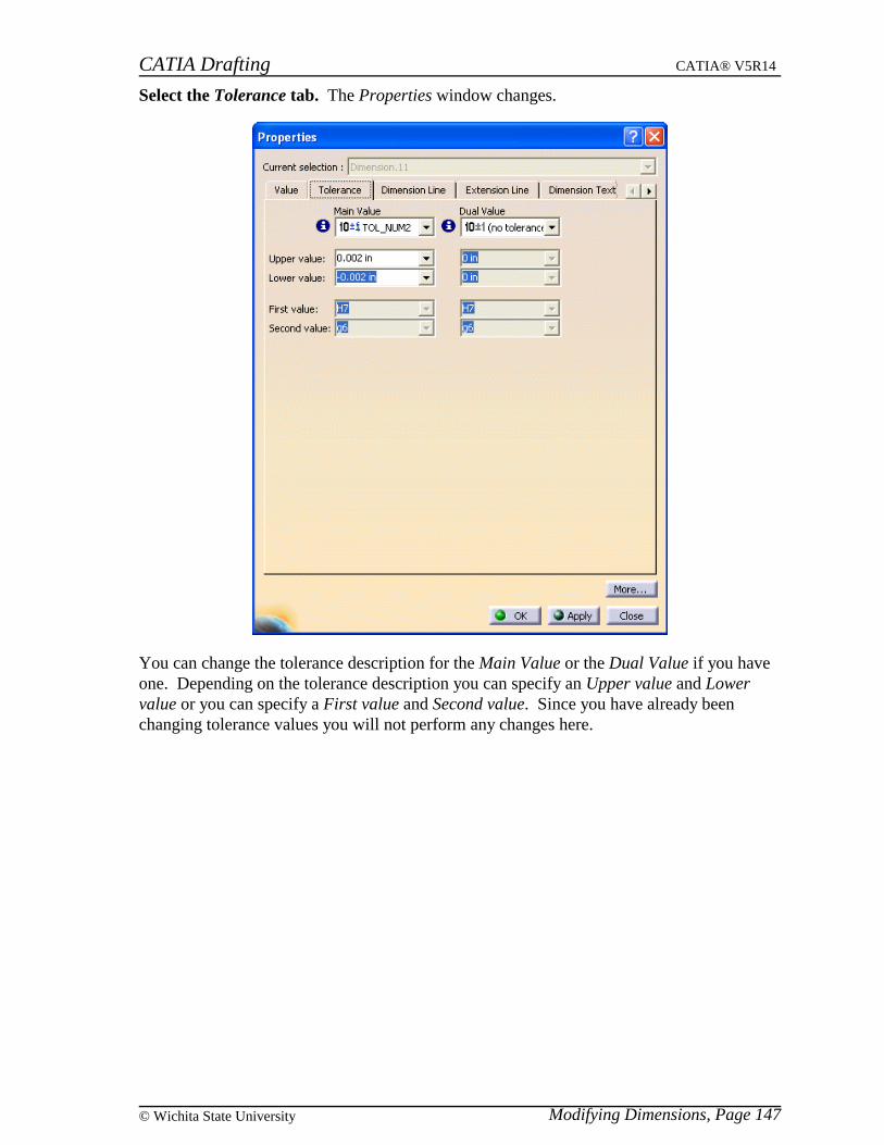
CATIA Drafting CATIA® V5R14
Modifying Dimensions, Page 147© Wichita State University
Select the Tolerance tab. The Properties window changes.
You can change the tolerance description for the Main Value or the Dual Value if you haveone. Depending on the tolerance description you can specify an Upper value and Lowervalue or you can specify a First value and Second value. Since you have already beenchanging tolerance values you will not perform any changes here.

CATIA Drafting CATIA® V5R14
Modifying Dimensions, Page 148 ©Wichita State University
Select the Dimension Line tab. The Properties window changes.
Dimension Line Allows you to display your dimension lines either regular, two partsor with one of two leaders. The options correspond to the four iconson the top toolbar. Depending on the Representation, you can specifythe other values. Thickness and Color pertains to the display of thedimension lines. The Leader Angle corresponds to the angle of thefirst part. If the Extension was not defined in the standard then youcould specify it here.
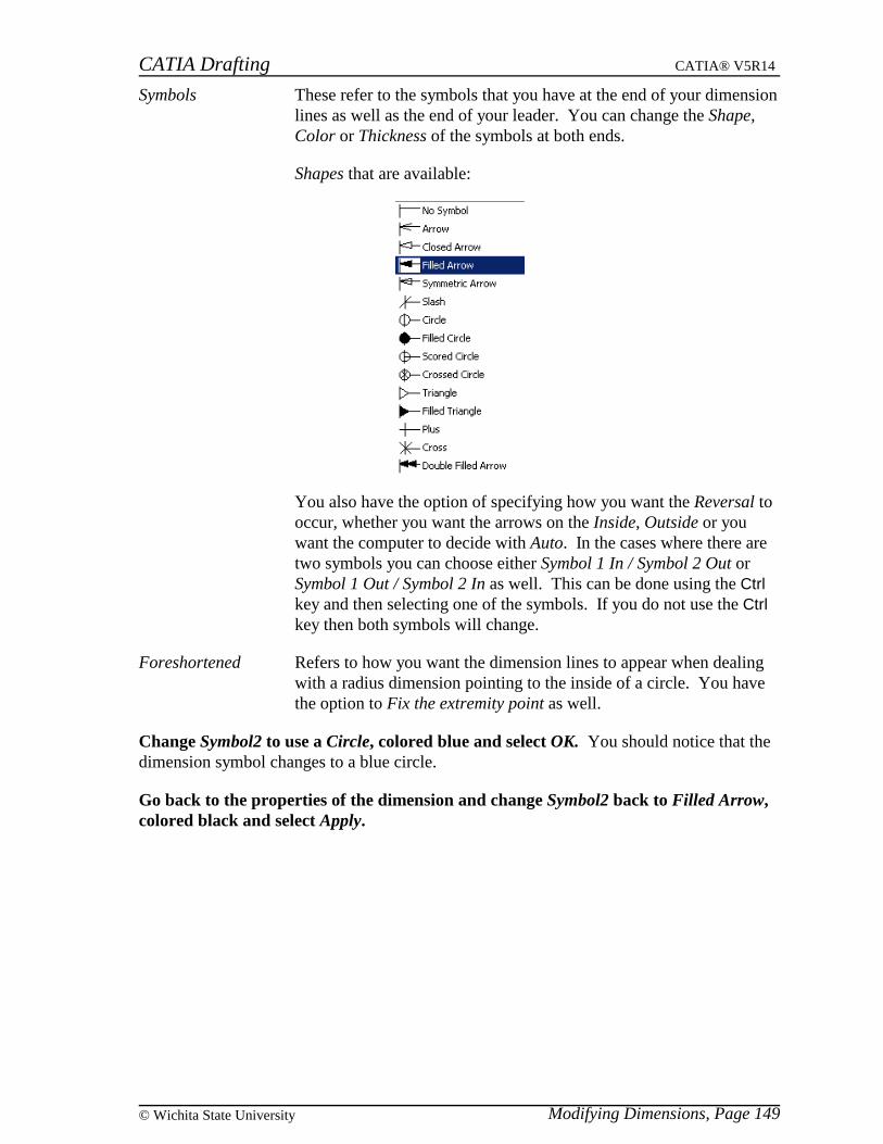
CATIA Drafting CATIA® V5R14
Modifying Dimensions, Page 149© Wichita State University
Symbols These refer to the symbols that you have at the end of your dimensionlines as well as the end of your leader. You can change the Shape,Color or Thickness of the symbols at both ends.
Shapes that are available:
You also have the option of specifying how you want the Reversal tooccur, whether you want the arrows on the Inside, Outside or youwant the computer to decide with Auto. In the cases where there aretwo symbols you can choose either Symbol 1 In / Symbol 2 Out orSymbol 1 Out / Symbol 2 In as well. This can be done using the Ctrlkey and then selecting one of the symbols. If you do not use the Ctrlkey then both symbols will change.
Foreshortened Refers to how you want the dimension lines to appear when dealingwith a radius dimension pointing to the inside of a circle. You havethe option to Fix the extremity point as well.
Change Symbol2 to use a Circle, colored blue and select OK. You should notice that thedimension symbol changes to a blue circle.
Go back to the properties of the dimension and change Symbol2 back to Filled Arrow,colored black and select Apply.
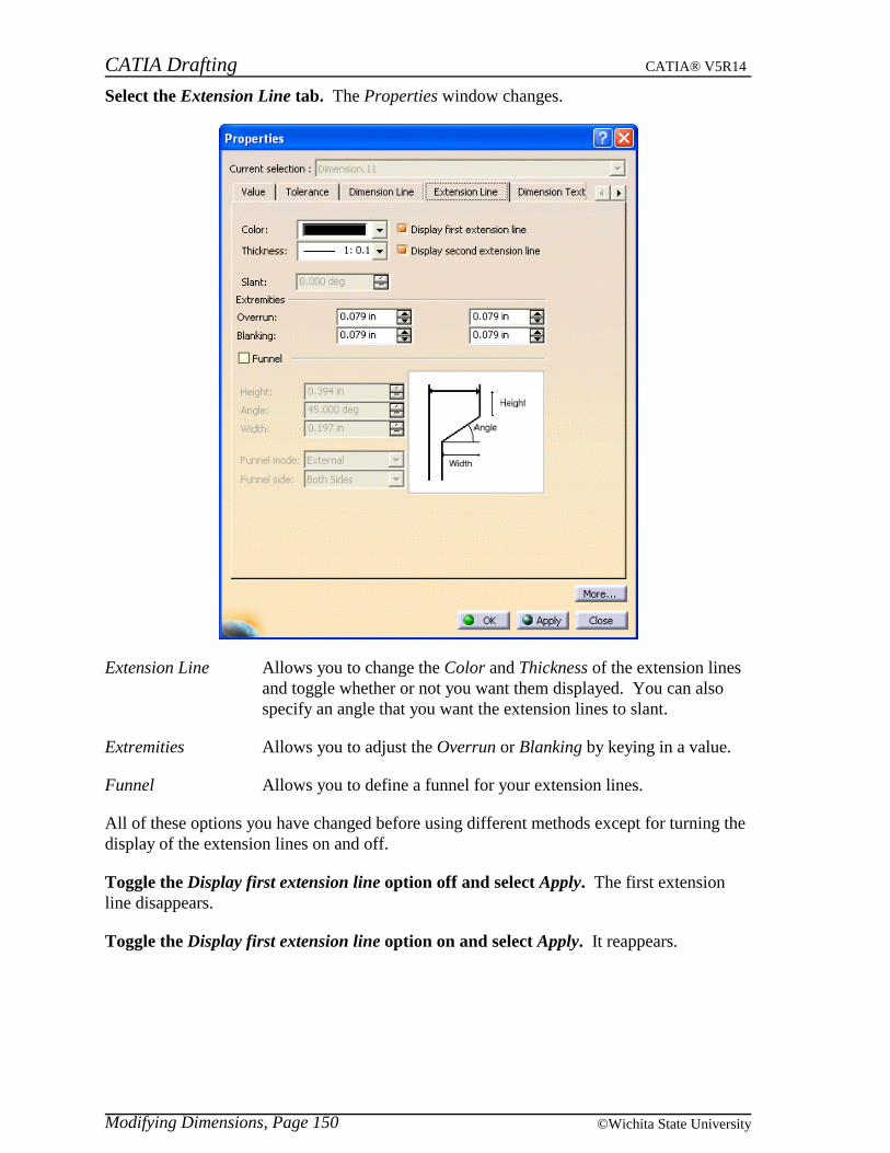
CATIA Drafting CATIA® V5R14
Modifying Dimensions, Page 150 ©Wichita State University
Select the Extension Line tab. The Properties window changes.
Extension Line Allows you to change the Color and Thickness of the extension linesand toggle whether or not you want them displayed. You can alsospecify an angle that you want the extension lines to slant.
Extremities Allows you to adjust the Overrun or Blanking by keying in a value.
Funnel Allows you to define a funnel for your extension lines.
All of these options you have changed before using different methods except for turning thedisplay of the extension lines on and off.
Toggle the Display first extension line option off and select Apply. The first extensionline disappears.
Toggle the Display first extension line option on and select Apply. It reappears.
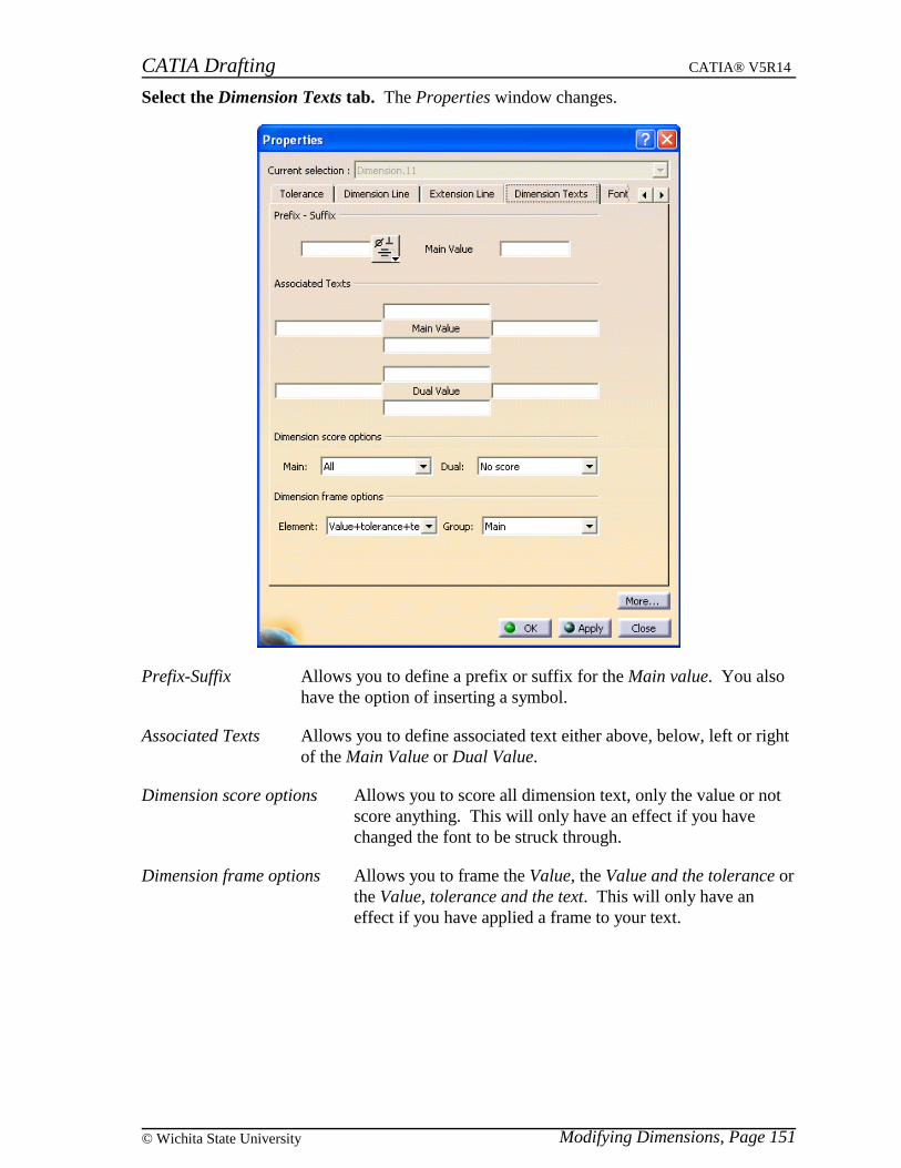
CATIA Drafting CATIA® V5R14
Modifying Dimensions, Page 151© Wichita State University
Select the Dimension Texts tab. The Properties window changes.
Prefix-Suffix Allows you to define a prefix or suffix for the Main value. You alsohave the option of inserting a symbol.
Associated Texts Allows you to define associated text either above, below, left or rightof the Main Value or Dual Value.
Dimension score options Allows you to score all dimension text, only the value or notscore anything. This will only have an effect if you havechanged the font to be struck through.
Dimension frame options Allows you to frame the Value, the Value and the tolerance orthe Value, tolerance and the text. This will only have aneffect if you have applied a frame to your text.
CATIA Drafting CATIA® V5R14
Modifying Dimensions, Page 152 ©Wichita State University
Under Associated Texts key in Top in the box above, Right in the box to the right,Bottom in the box below and Left in the box to the left of the Main Value and selectApply. You should notice the placement of the text around the dimension. The placementis determined as shown below.
Associated Text
Associated Text Prefix Main Value Suffix Associated Text
Associated Text
Change the Associated Texts to contain nothing and select Apply. This should removethe text from around the dimension.
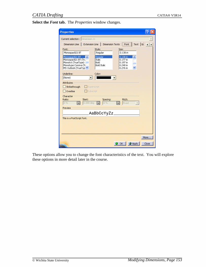
CATIA Drafting CATIA® V5R14
Modifying Dimensions, Page 153© Wichita State University
Select the Font tab. The Properties window changes.
These options allow you to change the font characteristics of the text. You will explorethese options in more detail later in the course.
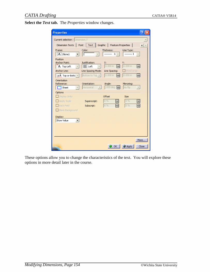
CATIA Drafting CATIA® V5R14
Modifying Dimensions, Page 154 ©Wichita State University
Select the Text tab. The Properties window changes.
These options allow you to change the characteristics of the text. You will explore theseoptions in more detail later in the course.
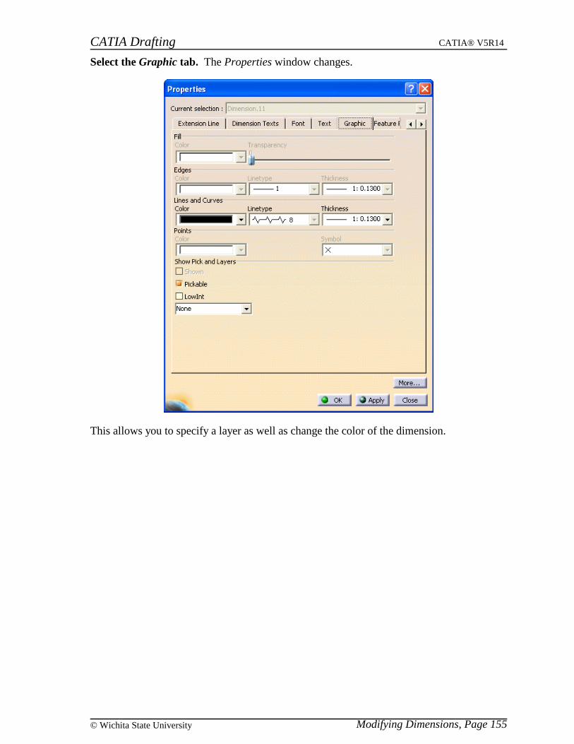
CATIA Drafting CATIA® V5R14
Modifying Dimensions, Page 155© Wichita State University
Select the Graphic tab. The Properties window changes.
This allows you to specify a layer as well as change the color of the dimension.
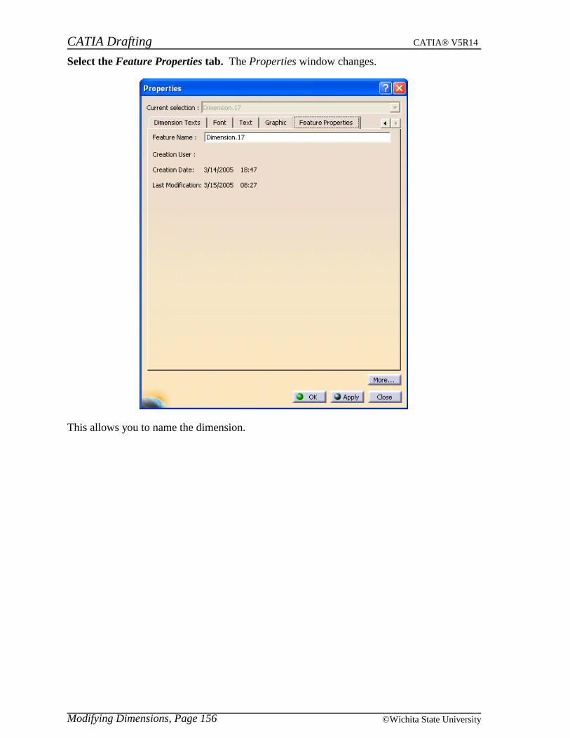
CATIA Drafting CATIA® V5R14
Modifying Dimensions, Page 156 ©Wichita State University
Select the Feature Properties tab. The Properties window changes.
This allows you to name the dimension.

CATIA Drafting CATIA® V5R14
Modifying Dimensions, Page 157© Wichita State University
Now that you know how to make modifications you will create and make changes to acouple of dimensions on the drawing.
Select Close and select off the dimension on the sheet. This should close the Propertieswindow and release the dimension.
Select the chamfer dimensions icon and select the chamfer as shown below. Remember,you have the option of selecting the reference surfaces that make up the chamfer.
Select the horizontal and vertical lines that touch the chamfer. Make sure you select thehorizontal line first.
Locate the dimension and then move it up and to the right. Notice that the chamfer isshown in terms of Length x Length according to the options set in the Tools Palette. Youwant the dimension to show in terms of Length x Angle, however you are going to do this bymodifying the Properties.
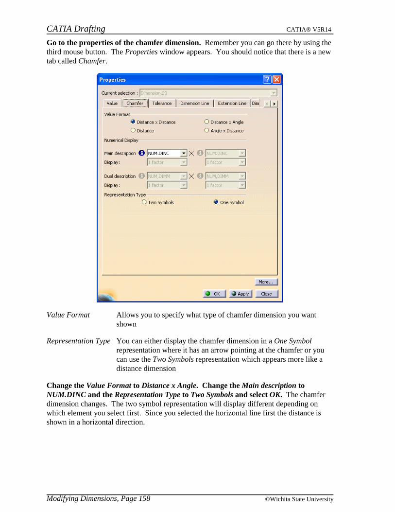
CATIA Drafting CATIA® V5R14
Modifying Dimensions, Page 158 ©Wichita State University
Go to the properties of the chamfer dimension. Remember you can go there by using thethird mouse button. The Properties window appears. You should notice that there is a newtab called Chamfer.
Value Format Allows you to specify what type of chamfer dimension you wantshown
Representation Type You can either display the chamfer dimension in a One Symbolrepresentation where it has an arrow pointing at the chamfer or youcan use the Two Symbols representation which appears more like adistance dimension
Change the Value Format to Distance x Angle. Change the Main description toNUM.DINC and the Representation Type to Two Symbols and select OK. The chamferdimension changes. The two symbol representation will display different depending onwhich element you select first. Since you selected the horizontal line first the distance isshown in a horizontal direction.
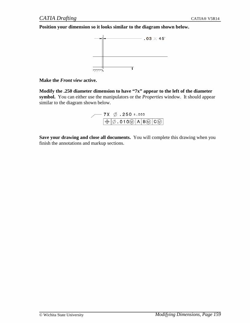
CATIA Drafting CATIA® V5R14
Modifying Dimensions, Page 159© Wichita State University
Position your dimension so it looks similar to the diagram shown below.
Make the Front view active.
Modify the .250 diameter dimension to have “7x” appear to the left of the diametersymbol. You can either use the manipulators or the Properties window. It should appearsimilar to the diagram shown below.
Save your drawing and close all documents. You will complete this drawing when youfinish the annotations and markup sections.

CATIA Drafting CATIA® V5R14
Modifying Dimensions, Page 160 ©Wichita State University
Analysis
You have the option of performing a dimensions analysis and it will show what dimensionshave bad placement.
Open the Dim Modify drawing. The drawing should contain four views with the Frontview active. You should also notice that some dimensions have already been placed on thedrawing. You are going to analyze these dimensions to see if you have any problems withthe placement of the dimensions.
Select the dimensions analysis icon. You may have to turn that toolbar on in order tosee the icon. You can do this by choosing the Analyze option under the pull down menuView, Toolbars. The Analyze window will appear. This performed an analysis of youractive view, in this case the Front view. Notice that it found 3 elements badly placed. Youhave the option of choosing an optimized list.
Total number of elements in the current list The number of elements that are badly placed.
Number of the pointed element As you scan through using the Scanner it willshow you which element number you arelooking at.
Scanner Allows you to step through the list one at atime forward or backward, jump to the end orbeginning and to update the list as you makechanges.
You should also notice that dimensions in the view are color coordinated. The highlightedelements are the ones that are badly placed. Notice that when two items interfere with oneanother both are counted as being badly placed. The optimized list takes this into accountand only counts that as one element.
Switch the option to Optimized list with the annotations badly placed. The Total numberof elements in the current list changes to 2 instead of 3. Sometimes this is preferredalthough as you correct a problem with them listed either way the number will change afteryou update the analysis.
Switch the option back to the List with the annotations badly placed. You are now goingto scan through the list and make changes as you go.
CATIA Drafting CATIA® V5R14
Modifying Dimensions, Page 161© Wichita State University
Select the next icon until you get to the view name. The view name interferes with the2.75 dimension.
Move the view name below the 3.25 dimension. This will locate the view name at thebottom of the view out of the way of all dimensions.
Select the update icon in the Analyze window. Now you are down to two elements thathave problems. One is the 2.00 radius and the other is the 2.75 dimension. The reason itthinks there is a problem is that if the dimension line of the 2.00 radius went to the center ofthe circle then it would interfere with the 2.75 dimension.
Select the next icon until you get to the 2.75 dimension. Notice a circle appears on top ofthe 2. This is where the center point of the circle is located. You need to move thedimension off of this center location.
Move the 2.75 dimension down a little so that it does not interfere with the centerlocation and select the update icon in the Analyze window. The number of elementschanges to 1.
Select the next icon. Notice that the radius dimension still thinks it interferes with the 0.75dimension. Notice the circle notation on the extension line of the 0.75 dimension. You willmodify the blanking of the 0.75 dimension so that it stops before that interfering location.
Select OK. This exits the Analyze window.
Modify the end of the .75 extension line to stop before that interfering location. Youcan do this by using the manipulators or the properties of the dimension.
Select the dimensions analysis icon again. It now states that there are no problems withyour placement of the dimensions. Depending on your company’s standards it may not benecessary to make the last two adjustments.
Select OK to exit the window.
Activate the top view and perform a dimensions analysis. There is only one badplacement in this view.
Modify the placement until there are not problems and exit the Analyze window.
You fixed all of the bad placements manually, however there are some tools that assist youin placing and aligning dimensions. You will explore those options next.
Close all documents. You do not need to save this drawing.
Note: The analysis option can also be accessed through the pull down menu Tools, Analyze.

CATIA Drafting CATIA® V5R14
Modifying Dimensions, Page 162 ©Wichita State University
Positioning
There are some positioning tools that can help you position your dimensions properly.These can be extremely useful when you are working with generated dimensions as you willlater in this course. In order to see these icons you may have to turn on the positioningtoolbar.
Turn on the Positioning toolbar. You can do this by choosing the Positioning optionunder the pull down menu View, Toolbars.
Open the Dim Modify drawing. This will open the same drawing that you used last timewithout the modifications.
Select the 1.50 and the .75 dimensions in the Front view. Make sure both are selected.
Select the line-up icon. This will allow you to line-up your dimensions automaticallywithout having to do it manually. You also have the option of using the third mouse buttonand selecting Line-Up. You have the option of specifying a reference line or to select areference from free space.
Select the rightmost vertical line in the Front view. This will use that line as thereference element. The Line Up window appears.
Offset to reference The distance from the reference element to thefirst dimension and the angle from thereference element to the first dimension
Offset between dimensions The distance between each dimension and theangle between each dimension
Align stacked dimension values Aligns the values of the stacked dimensions
Align cumulated dimension values Aligns the values of the cumulated dimensions
Automatically add a funnel Adds a funnel on cumulated dimension valuesif necessary
Only organize dimensions into systems If activated the first dimension (interior) willnot move and the other dimensions will bebased on your offset
CATIA Drafting CATIA® V5R14
Modifying Dimensions, Page 163© Wichita State University
Make sure that the Only organize dimensions into systems option is off and enter 2.0 forthe Offset to reference and 2.0 for the Offset between dimensions and select OK. Thetwo dimensions are positioned. The 0.75 dimension is one inch from the reference element.The 1.50 dimension is one inch from the 0.75 dimension. If you would have had the Onlyorganize dimensions into systems option on then the 0.75 dimension would not have movedand the 1.50 dimension would have been an inch from the 0.75 dimension. The reason theyare only one inch apart is because the view scale is 2:1.
Select the .75 and the 1.00 inch dimensions.
Select the line-up icon.
Select the leftmost vertical line in the Front view. This will use that line as the referenceelement.
Make sure the Only organize dimensions into systems option is off and enter 1.0 for theOffset to reference and 1.5 for the Offset between dimensions and select OK. Thedimensions move.
The line-up icon works very well to position dimensions uniformly without you having to
manually do it. The other line up option is the align into system icon. This icon will
use the default settings that are defined in pull down menu Tools, Options, MechanicalDesign, Drafting, Dimensions tab. It will align the dimensions just like the line up iconexcept it will always have the Only organize dimensions into systems option on. Thereforethe first dimension will not move and the spacing between the other dimensions isdetermined by the default settings. If everything is set up correctly this can be a very quickway of aligning dimensions.
There is another option that works well to position dimensions as well called dimensionpositioning. The dimension positioning icon is extremely useful when you are working withgenerated dimensions.
Activate the Top view. You are going to use the dimension positioning icon toautomatically position all your dimensions.

CATIA Drafting CATIA® V5R14
Modifying Dimensions, Page 164 ©Wichita State University
Select the dimension positioning icon. Notice that by selecting the icon all of yourdimensions position nicely.
Activate the Front view and select the dimension positioning icon. Once again yourdimensions position nicely and your drawing should appear similar to the one shown below.You will now learn how to create and remove interruptions on your extension lines.
Note: The positioning option will not change the angle of the dimensions, such as the .63diameter dimension.
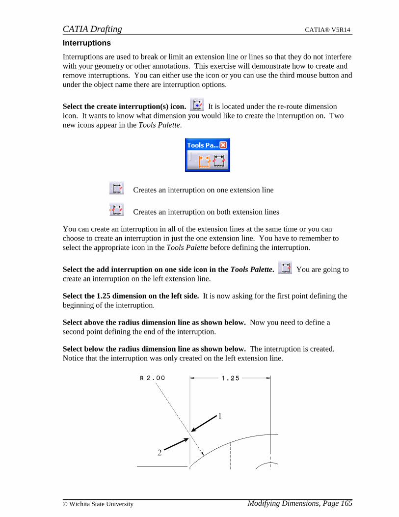
CATIA Drafting CATIA® V5R14
Modifying Dimensions, Page 165© Wichita State University
Interruptions
Interruptions are used to break or limit an extension line or lines so that they do not interferewith your geometry or other annotations. This exercise will demonstrate how to create andremove interruptions. You can either use the icon or you can use the third mouse button andunder the object name there are interruption options.
Select the create interruption(s) icon. It is located under the re-route dimensionicon. It wants to know what dimension you would like to create the interruption on. Twonew icons appear in the Tools Palette.
Creates an interruption on one extension line
Creates an interruption on both extension lines
You can create an interruption in all of the extension lines at the same time or you canchoose to create an interruption in just the one extension line. You have to remember toselect the appropriate icon in the Tools Palette before defining the interruption.
Select the add interruption on one side icon in the Tools Palette. You are going tocreate an interruption on the left extension line.
Select the 1.25 dimension on the left side. It is now asking for the first point defining thebeginning of the interruption.
Select above the radius dimension line as shown below. Now you need to define asecond point defining the end of the interruption.
Select below the radius dimension line as shown below. The interruption is created.Notice that the interruption was only created on the left extension line.
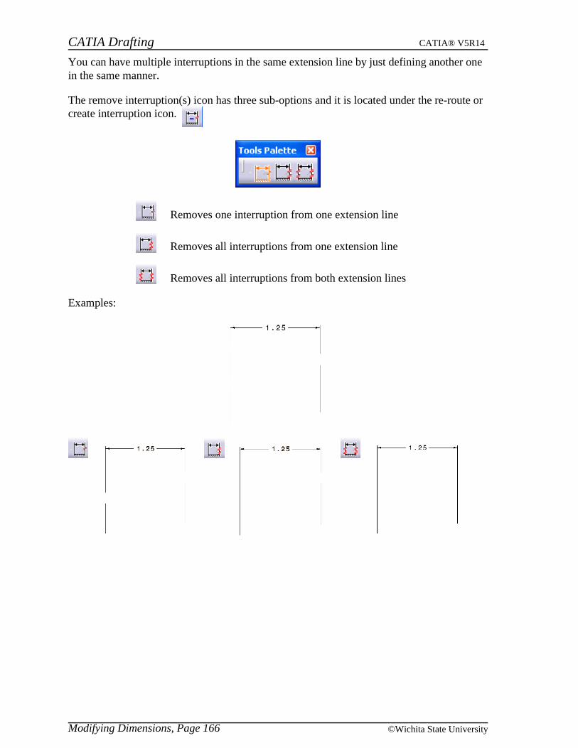
CATIA Drafting CATIA® V5R14
Modifying Dimensions, Page 166 ©Wichita State University
You can have multiple interruptions in the same extension line by just defining another onein the same manner.
The remove interruption(s) icon has three sub-options and it is located under the re-route orcreate interruption icon.
Removes one interruption from one extension line
Removes all interruptions from one extension line
Removes all interruptions from both extension lines
Examples:

CATIA Drafting CATIA® V5R14
Modifying Dimensions, Page 167© Wichita State University
Update
You will now see the effects of making changes to your part and updating the views.
Open the Dim Modify part. Keep your drawing open.
In Sketch.1 change the 2.75 constraint to be 2.5 and exit the sketcher. You have nowchanged your part and the views in your drawing will need to be updated.
Switch to your drawing. Notice the update icon is available.
Select the update icon. Notice your dimensions automatically adjusted.
Switch back to your part and modify Sketch.1 so it does not have the 1.5 inch wideopening as shown below.
Switch back to your drawing and update the views. Notice that two of your dimensionsin the Top view change to a pinkish color. This is signifying that they cannot be updated.The reason is obvious, the elements that they were dimensioning are now gone.
The color of a dimension means different things. There is an analysis display modeoption that can be turned on and off. It is located in the Tools toolbar. If it is on, then youwill see the colors change as the status of a dimension changes.
Select the analysis display mode icon to deactivate it. Notice the two dimensionschange back to their original color.

CATIA Drafting CATIA® V5R14
Modifying Dimensions, Page 168 ©Wichita State University
The colors can be modified by using the pull down menu Tools, Options.
Go to the pull down menu Tools, Options, Mechanical Design, Drafting, Dimension tab.In this tab you should see an Analysis Display Mode area.
Turn the Activate analysis display mode on and then select the Types and colors...button. The Types and colors of dimensions window should appear. This is where thecolors can be set along with defining what each color means. Do you remember when youcreated the true dimension it appeared purple?
Select Close and OK on the Options window. Notice the two dimensions are now pinkagain. You turned the mode back on using the pull down menu.
Delete the two dimensions. They are no longer needed since the geometry does not exist.
You are now ready to learn how to generate dimensions from the constraints on your part.
Close all documents. There is no reason to save either one of the Dim Modify documents.
CATIA Drafting CATIA® V5R14
Generating Dimensions, Page 169© Wichita State University
Generating Dimensions
Generating dimensions is a quick way of creating dimensions that have already been definedwith constraints in your Part. There are two options to generating dimensions, either all atonce or step by step. There have been some bugs in the software, therefore the appropriatedimensions may not appear highlighted when doing analysis after generation. However, thegenerating portion is working, therefore it should not cause the exercise to fail.
Open the Generate Dim drawing and part. You are going to look at the constraints of thepart first to get an idea of what is happening when you generate dimensions.
Switch to the part and look at Sketch.1 and its constraints. Notice that the rest of theelements are fillets and holes.
Exit the sketcher and switch back to the drawing. Before you generate the dimensionsall at once you are going to turn on the option to filter before generation. This will allowyou to specify the filters you want to use before generating the dimensions.
Go to pull down menu Tools, Options, Mechanical Design, Drafting and the Generationtab.
Turn the Filters before generation option on and select OK. You should also notice thatthe Analysis after generation option is already selected.
Select the Front view. It should appear highlighted. By selecting a view or views beforeselecting the generate dimensions icon, dimensions will only be generated for that view orviews.
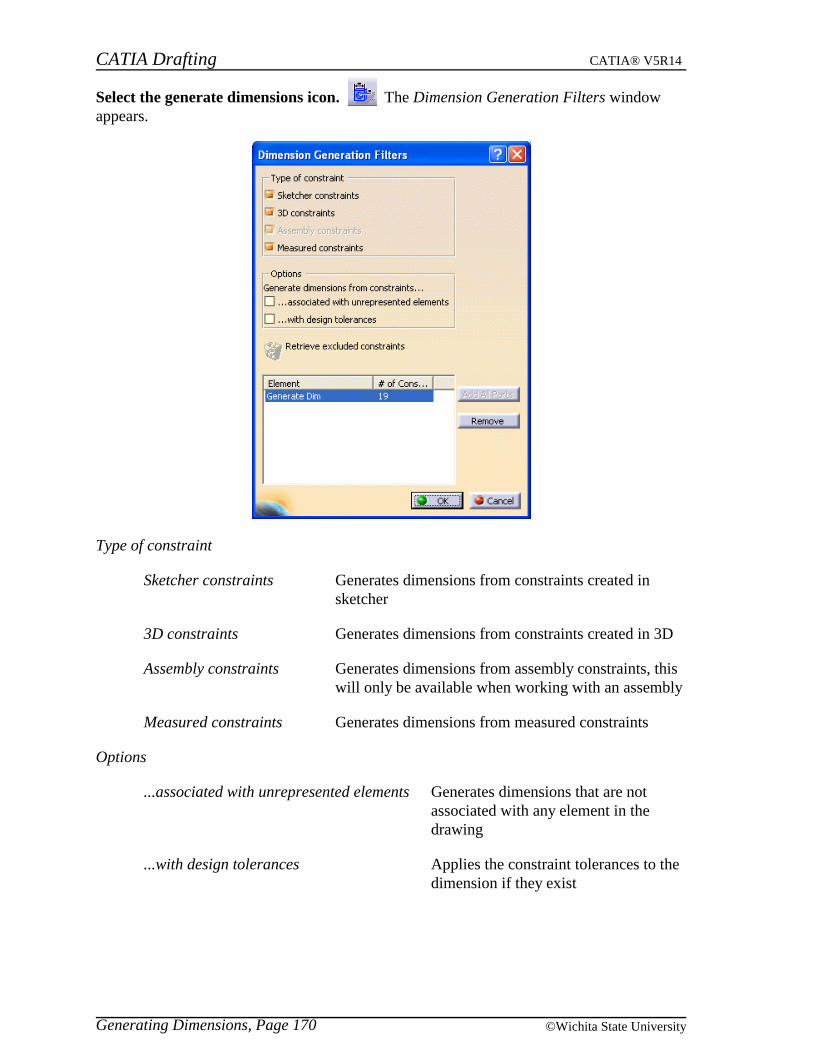
CATIA Drafting CATIA® V5R14
Generating Dimensions, Page 170 ©Wichita State University
Select the generate dimensions icon. The Dimension Generation Filters windowappears.
Type of constraint
Sketcher constraints Generates dimensions from constraints created insketcher
3D constraints Generates dimensions from constraints created in 3D
Assembly constraints Generates dimensions from assembly constraints, thiswill only be available when working with an assembly
Measured constraints Generates dimensions from measured constraints
Options
...associated with unrepresented elements Generates dimensions that are notassociated with any element in thedrawing
...with design tolerances Applies the constraint tolerances to thedimension if they exist
CATIA Drafting CATIA® V5R14
Generating Dimensions, Page 171© Wichita State University
Retrieve excluded constraints Allows you to recover a constraint that youexcluded before and have it regenerated. Onlyavailable if you have excluded someconstraints
Add All Parts Adds all the parts associated with an assembly. This is only availableif you are working with an assembly.
Remove Removes the element from the list.
The list will specify the number of constraints for each element. In this case there are 19constraints in the Generate Dim part.
Select the 3D constraints option only. Make sure no other options are selected. You aregoing to generate dimensions from just the 3D constraints.
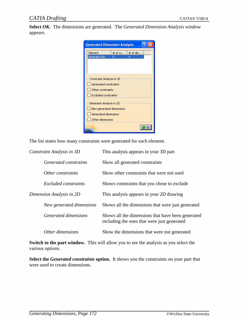
CATIA Drafting CATIA® V5R14
Generating Dimensions, Page 172 ©Wichita State University
Select OK. The dimensions are generated. The Generated Dimension Analysis windowappears.
The list states how many constraints were generated for each element.
Constraint Analysis in 3D This analysis appears in your 3D part
Generated constraints Show all generated constraints
Other constraints Show other constraints that were not used
Excluded constraints Shows constraints that you chose to exclude
Dimension Analysis in 2D This analysis appears in your 2D drawing
New generated dimensions Shows all the dimensions that were just generated
Generated dimensions Shows all the dimensions that have been generatedincluding the ones that were just generated
Other dimensions Show the dimensions that were not generated
Switch to the part window. This will allow you to see the analysis as you select thevarious options.
Select the Generated constraints option. It shows you the constraints on your part thatwere used to create dimensions.
CATIA Drafting CATIA® V5R14
Generating Dimensions, Page 173© Wichita State University
Select the Other constraints option. This shows you the constraints that are available butnot used to create dimensions. Since you have not excluded any constraints yet theExcluded constraints option will not show anything.
Switch back to your drawing.
Select the New generated dimensions option. Notice that all of the dimensions arehighlighted. All of the dimensions were newly generated. The Generated dimensionsoption will show the same thing and the Other dimensions shows nothing new since all ofthe dimensions so far are generated from 3D.
Select OK. This will close the window. You will now generate all of the constraintsinstead of just the 3D constraints. You will also generate dimensions on all of the viewsinstead of just the Front view.
Select the generate dimensions icon. The Dimension Generation Filters window appears.
Select all the options for Type of constraint and turn on the ...associated withunrepresented elements option and select OK. Some more dimensions get generated andthe Generated Dimension Analysis window appears.
Select the New generated dimensions option. Notice that only the newly generateddimensions are highlighted. All of the dimensions may be highlighted, there has been a bugin the software for some time in this regard.
Select the Generated dimensions options. Now all of the dimensions highlight since all ofthem are generated dimensions.
Select OK. The window closes. You are now going to use your positioning icons toposition these dimensions.
Select the dimension positioning icon. You can either select the icon or choose the optionunder the pull down menu Tools, Positioning. All of the dimensions in the Front view arepositioned.
Activate the Top view and select the dimension positioning icon. The dimensions arepositioned in that view as well. This option is very nice to get a beginning position for all ofthe dimensions, however you may still have to do some modifications in order to clarify thedimensioning of your part. You also may have to add additional dimensions in order tofinish your drawing.
Your generated dimension can be used to control the 3D constraints. This can only occur ifthe option under Tools, Options is set accordingly. This can be a very dangerous option soyou will be introduced to it and then you will set the option so it cannot be done.
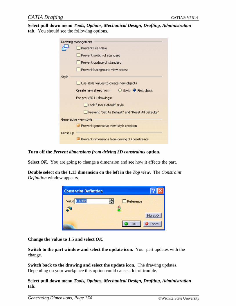
CATIA Drafting CATIA® V5R14
Generating Dimensions, Page 174 ©Wichita State University
Select pull down menu Tools, Options, Mechanical Design, Drafting, Administrationtab. You should see the following options.
Turn off the Prevent dimensions from driving 3D constraints option.
Select OK. You are going to change a dimension and see how it affects the part.
Double select on the 1.13 dimension on the left in the Top view. The ConstraintDefinition window appears.
Change the value to 1.5 and select OK.
Switch to the part window and select the update icon. Your part updates with thechange.
Switch back to the drawing and select the update icon. The drawing updates.Depending on your workplace this option could cause a lot of trouble.
Select pull down menu Tools, Options, Mechanical Design, Drafting, Administrationtab.
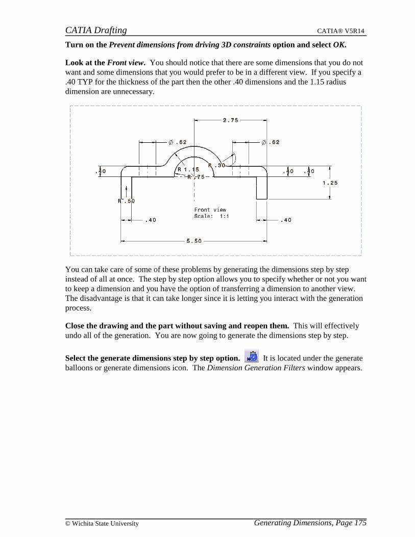
CATIA Drafting CATIA® V5R14
Generating Dimensions, Page 175© Wichita State University
Turn on the Prevent dimensions from driving 3D constraints option and select OK.
Look at the Front view. You should notice that there are some dimensions that you do notwant and some dimensions that you would prefer to be in a different view. If you specify a.40 TYP for the thickness of the part then the other .40 dimensions and the 1.15 radiusdimension are unnecessary.
You can take care of some of these problems by generating the dimensions step by stepinstead of all at once. The step by step option allows you to specify whether or not you wantto keep a dimension and you have the option of transferring a dimension to another view.The disadvantage is that it can take longer since it is letting you interact with the generationprocess.
Close the drawing and the part without saving and reopen them. This will effectivelyundo all of the generation. You are now going to generate the dimensions step by step.
Select the generate dimensions step by step option. It is located under the generateballoons or generate dimensions icon. The Dimension Generation Filters window appears.
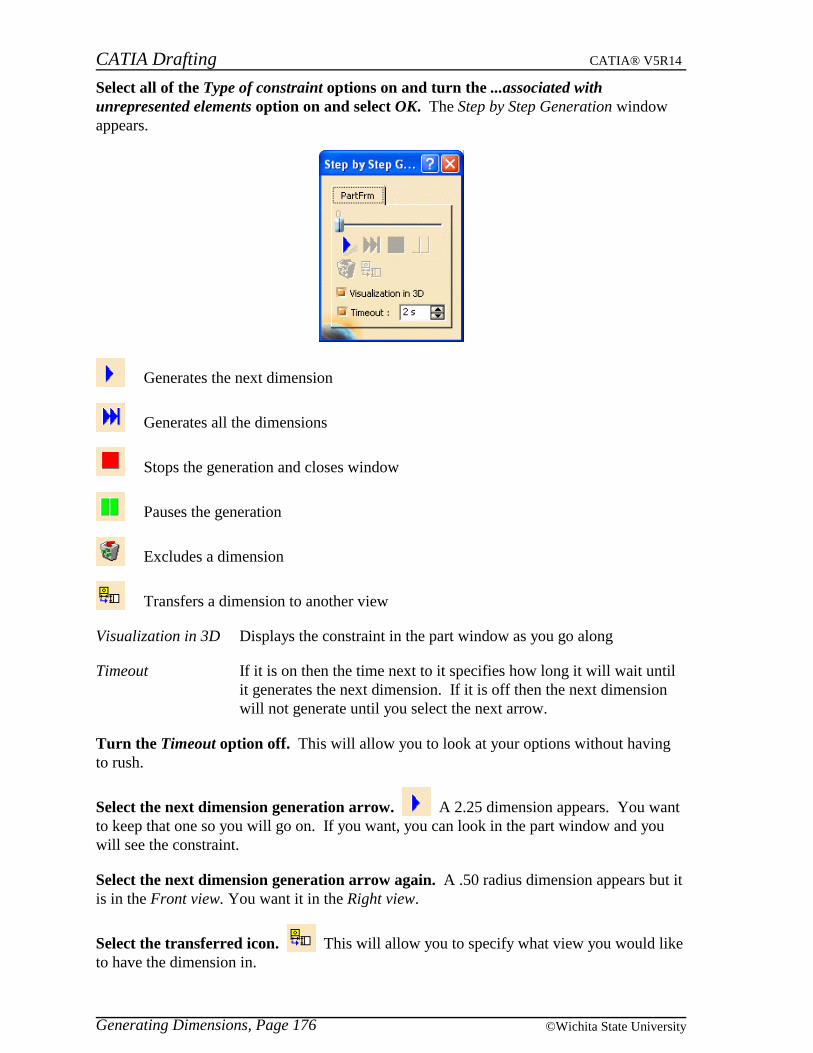
CATIA Drafting CATIA® V5R14
Generating Dimensions, Page 176 ©Wichita State University
Select all of the Type of constraint options on and turn the ...associated withunrepresented elements option on and select OK. The Step by Step Generation windowappears.
Generates the next dimension
Generates all the dimensions
Stops the generation and closes window
Pauses the generation
Excludes a dimension
Transfers a dimension to another view
Visualization in 3D Displays the constraint in the part window as you go along
Timeout If it is on then the time next to it specifies how long it will wait untilit generates the next dimension. If it is off then the next dimensionwill not generate until you select the next arrow.
Turn the Timeout option off. This will allow you to look at your options without havingto rush.
Select the next dimension generation arrow. A 2.25 dimension appears. You wantto keep that one so you will go on. If you want, you can look in the part window and youwill see the constraint.
Select the next dimension generation arrow again. A .50 radius dimension appears but itis in the Front view. You want it in the Right view.
Select the transferred icon. This will allow you to specify what view you would liketo have the dimension in.
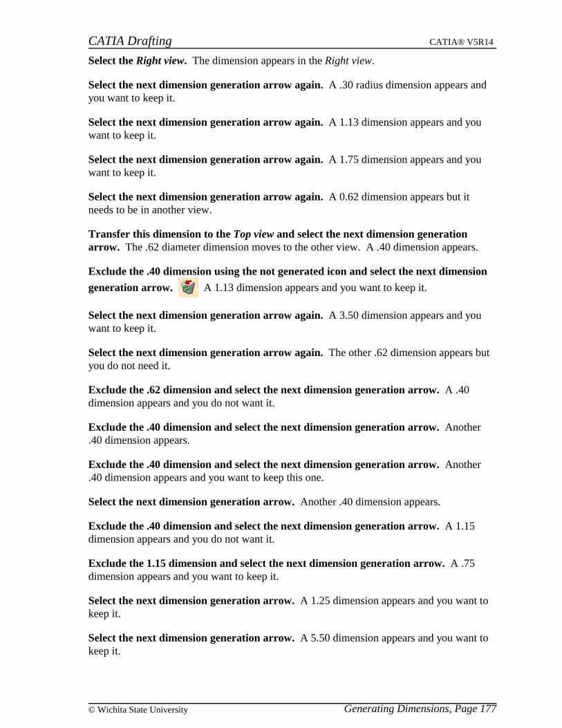
CATIA Drafting CATIA® V5R14
Generating Dimensions, Page 177© Wichita State University
Select the Right view. The dimension appears in the Right view.
Select the next dimension generation arrow again. A .30 radius dimension appears andyou want to keep it.
Select the next dimension generation arrow again. A 1.13 dimension appears and youwant to keep it.
Select the next dimension generation arrow again. A 1.75 dimension appears and youwant to keep it.
Select the next dimension generation arrow again. A 0.62 dimension appears but itneeds to be in another view.
Transfer this dimension to the Top view and select the next dimension generationarrow. The .62 diameter dimension moves to the other view. A .40 dimension appears.
Exclude the .40 dimension using the not generated icon and select the next dimension
generation arrow. A 1.13 dimension appears and you want to keep it.
Select the next dimension generation arrow again. A 3.50 dimension appears and youwant to keep it.
Select the next dimension generation arrow again. The other .62 dimension appears butyou do not need it.
Exclude the .62 dimension and select the next dimension generation arrow. A .40dimension appears and you do not want it.
Exclude the .40 dimension and select the next dimension generation arrow. Another.40 dimension appears.
Exclude the .40 dimension and select the next dimension generation arrow. Another.40 dimension appears and you want to keep this one.
Select the next dimension generation arrow. Another .40 dimension appears.
Exclude the .40 dimension and select the next dimension generation arrow. A 1.15dimension appears and you do not want it.
Exclude the 1.15 dimension and select the next dimension generation arrow. A .75dimension appears and you want to keep it.
Select the next dimension generation arrow. A 1.25 dimension appears and you want tokeep it.
Select the next dimension generation arrow. A 5.50 dimension appears and you want tokeep it.
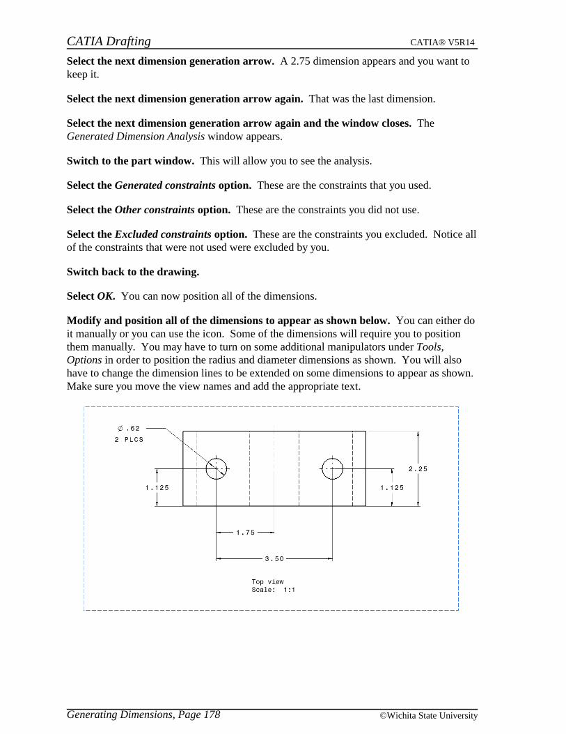
CATIA Drafting CATIA® V5R14
Generating Dimensions, Page 178 ©Wichita State University
Select the next dimension generation arrow. A 2.75 dimension appears and you want tokeep it.
Select the next dimension generation arrow again. That was the last dimension.
Select the next dimension generation arrow again and the window closes. TheGenerated Dimension Analysis window appears.
Switch to the part window. This will allow you to see the analysis.
Select the Generated constraints option. These are the constraints that you used.
Select the Other constraints option. These are the constraints you did not use.
Select the Excluded constraints option. These are the constraints you excluded. Notice allof the constraints that were not used were excluded by you.
Switch back to the drawing.
Select OK. You can now position all of the dimensions.
Modify and position all of the dimensions to appear as shown below. You can either doit manually or you can use the icon. Some of the dimensions will require you to positionthem manually. You may have to turn on some additional manipulators under Tools,Options in order to position the radius and diameter dimensions as shown. You will alsohave to change the dimension lines to be extended on some dimensions to appear as shown.Make sure you move the view names and add the appropriate text.

CATIA Drafting CATIA® V5R14
Generating Dimensions, Page 179© Wichita State University
You need to add one additional dimension to the Front view to state what the radius of thecorner is and then you need to either adjust the blanking or create interruptions to get theextension lines off of the center and axis lines.
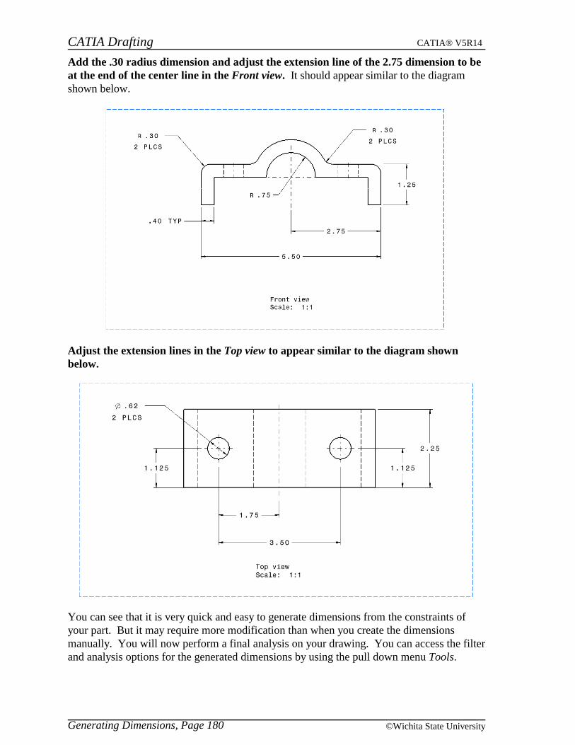
CATIA Drafting CATIA® V5R14
Generating Dimensions, Page 180 ©Wichita State University
Add the .30 radius dimension and adjust the extension line of the 2.75 dimension to beat the end of the center line in the Front view. It should appear similar to the diagramshown below.
Adjust the extension lines in the Top view to appear similar to the diagram shownbelow.
You can see that it is very quick and easy to generate dimensions from the constraints ofyour part. But it may require more modification than when you create the dimensionsmanually. You will now perform a final analysis on your drawing. You can access the filterand analysis options for the generated dimensions by using the pull down menu Tools.

CATIA Drafting CATIA® V5R14
Generating Dimensions, Page 181© Wichita State University
Select the Analysis option under the pull down menu Tools, Dimension generation. TheGenerated Dimension Analysis window appears.
Select on the Generated dimensions option. Almost all of the dimensions highlight.
Select on the Other dimensions option and turn off the Generated dimensions option.Only the .30 radius dimension that you manually created is highlighted. The last topic thatneeds to be looked at is how do you get dimensions generated that you have excluded.
Select OK.
Save your drawing. You will want to save now because what you are getting ready to dowill not need to be saved.
Select the generate dimensions icon. The Dimension Generation Filters window appears.Notice that the retrieve excluded constraints icon is available.
Make sure all of the options are on under Type of constraint and select OK. TheGenerated Dimension Analysis window appears.
Select the New generated dimensions option. Notice that there were not any newdimensions generated. Also you should note that the dimensions that have already beengenerated were not affected.
Select OK.
Select the generate dimensions icon again. This time you are going to recover aconstraint that you have excluded.
Select the retrieve excluded constraints icon. This will retrieve the constraints thatwere excluded.
Select OK. The Generated Dimension Analysis window appears.
Select the New generated dimensions option. The recovered dimensions are highlighted.You have the option to do the same using the step by step method since this is an option ofthe filter. With the step by step method you can then exclude the ones that you still do notwant and only recover the ones that you do want instead of recovering all of them.
Select OK. This concludes generating dimensions.
You should now be able to create, modify and generate all dimensions necessary for thecompletion of your drawing. However, a drawing normally will also require someannotations and symbols. The next section will cover those options.
Close all documents. You do not need to save any of them.

CATIA Drafting CATIA® V5R14
Generating Dimensions, Page 182 ©Wichita State University
This page is intentionally left blank.

CATIA Drafting CATIA® V5R14
Creating Text, Page 183© Wichita State University
Annotations
Annotations and symbols are normally required to finish a drawing. Annotations are used toconvey notes and information to the downstream user. Symbols are used to represent itemssuch as part numbers and welds. This section will cover the various tools you haveavailable to create annotations and symbols.
Creating Text
Open the Annotations drawing and part. This will allow you to work with items inboth windows. The drawing should contain four views with the Front view active.
Select the text icon. It is located under the datum target icon. This will allow you tocreate text.
Select a location in the Front view to the right of the extension. This defines the anchorpoint for the text. A Text Editor window appears. In this window you can type your text.
Key in Watch for extension and select OK. Make sure you do not press Enter or you willadd an additional line. The text appears. You can drag the text around to any location byusing the first mouse button.
Drag the text to the approximate location as shown below.
Create text that says To the right underneath and to the right of the last one.
Create text that says To the left underneath and to the left of the first piece of text.Now you will create text that is associated to a piece of geometry.

CATIA Drafting CATIA® V5R14
Creating Text, Page 184 ©Wichita State University
Select the text icon and then select the left vertical line of the extension. The TextEditor appears.
Key in Left side and select OK. The text appears.
Drag the text to the left of the extension as shown below.
Notice that all of the text has the same graphical properties. You can set the properties ofthe text before you create it by using the top toolbar. However, you will investigate theseoptions when you modify text.
Select the text icon and position the text below and to the right of the geometry in theview.

CATIA Drafting CATIA® V5R14
Creating Text, Page 185© Wichita State University
Key in This is press Enter, key in a multi-line press Enter, key in piece of text andselect OK. This should create a string of text that spans three lines as shown below.
Make the Top view active. You are now going to create text with a leader.
Select the text with leader icon. It is located under the text icon. You will select anelement to position the anchor point of the arrow head.
Select the small circle on the right. You should see an arrow appear that you can drag toposition the anchor point of the text.
Drag the arrow up and to the right and define the anchor point for the text. The TextEditor window appears.

CATIA Drafting CATIA® V5R14
Creating Text, Page 186 ©Wichita State University
Key in Hole and select OK. You have some positioning manipulators appear. Position thetext as shown below and select in the view off the text. The text with leader is created.
Those are the options that you have to create text. There are a lot of modifications that youcan perform on the text however. You will explore these modifications next.
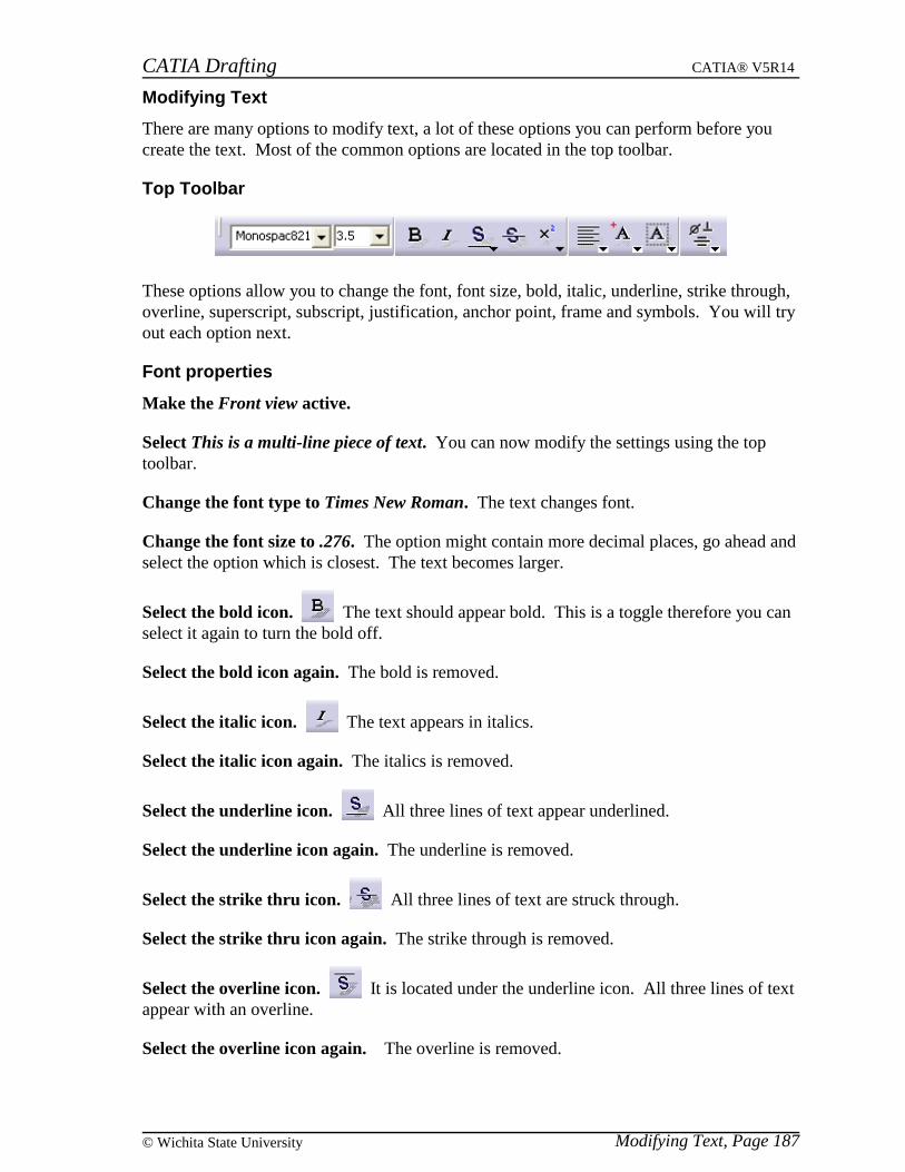
CATIA Drafting CATIA® V5R14
Modifying Text, Page 187© Wichita State University
Modifying Text
There are many options to modify text, a lot of these options you can perform before youcreate the text. Most of the common options are located in the top toolbar.
Top Toolbar
These options allow you to change the font, font size, bold, italic, underline, strike through,overline, superscript, subscript, justification, anchor point, frame and symbols. You will tryout each option next.
Font properties
Make the Front view active.
Select This is a multi-line piece of text. You can now modify the settings using the toptoolbar.
Change the font type to Times New Roman. The text changes font.
Change the font size to .276. The option might contain more decimal places, go ahead andselect the option which is closest. The text becomes larger.
Select the bold icon. The text should appear bold. This is a toggle therefore you canselect it again to turn the bold off.
Select the bold icon again. The bold is removed.
Select the italic icon. The text appears in italics.
Select the italic icon again. The italics is removed.
Select the underline icon. All three lines of text appear underlined.
Select the underline icon again. The underline is removed.
Select the strike thru icon. All three lines of text are struck through.
Select the strike thru icon again. The strike through is removed.
Select the overline icon. It is located under the underline icon. All three lines of textappear with an overline.
Select the overline icon again. The overline is removed.

CATIA Drafting CATIA® V5R14
Modifying Text, Page 188 ©Wichita State University
Select the superscript icon. The text appears superscripted.
Select the superscript icon again. The superscript is removed.
Select the subscript icon. It is located under the superscript icon. The text appearssubscripted.
Select the subscript icon again. The subscript is removed.
You should realize that you can have more than one property assigned to text at a giventime. It is possible to have a piece of text be bold, italic, underlined or overlined, struckthrough, superscript or subscript. The only options that can not be on at the same time isunderline and overline; and superscript and subscript.
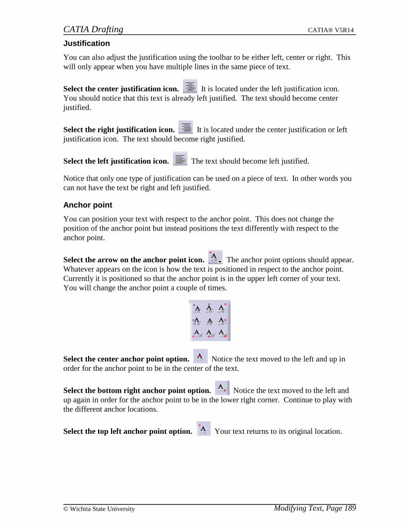
CATIA Drafting CATIA® V5R14
Modifying Text, Page 189© Wichita State University
Justification
You can also adjust the justification using the toolbar to be either left, center or right. Thiswill only appear when you have multiple lines in the same piece of text.
Select the center justification icon. It is located under the left justification icon.You should notice that this text is already left justified. The text should become centerjustified.
Select the right justification icon. It is located under the center justification or leftjustification icon. The text should become right justified.
Select the left justification icon. The text should become left justified.
Notice that only one type of justification can be used on a piece of text. In other words youcan not have the text be right and left justified.
Anchor point
You can position your text with respect to the anchor point. This does not change theposition of the anchor point but instead positions the text differently with respect to theanchor point.
Select the arrow on the anchor point icon. The anchor point options should appear.Whatever appears on the icon is how the text is positioned in respect to the anchor point.Currently it is positioned so that the anchor point is in the upper left corner of your text.You will change the anchor point a couple of times.
Select the center anchor point option. Notice the text moved to the left and up inorder for the anchor point to be in the center of the text.
Select the bottom right anchor point option. Notice the text moved to the left andup again in order for the anchor point to be in the lower right corner. Continue to play withthe different anchor locations.
Select the top left anchor point option. Your text returns to its original location.

CATIA Drafting CATIA® V5R14
Modifying Text, Page 190 ©Wichita State University
Frame
You have the option to add a variety of frames to your text. You will explore a few ofthem.
Select the arrow on the frame icon. The frame options should appear.
The frames with the little locks on them are fixed sized frames defined in the standards file.This becomes useful when your company has a set size for certain frames and it is up to youto fit your text within the frame by modifying its size. The other ones are variable sizedframes and will adjust to fit the text.
Select the rectangle frame option. A rectangular frame appears around the text.
Select the circle frame option. A circular frame appears around the text.
Select the left flag frame option. Feel free to play around with the other frameoptions but make sure you set the frame to this option before continuing.
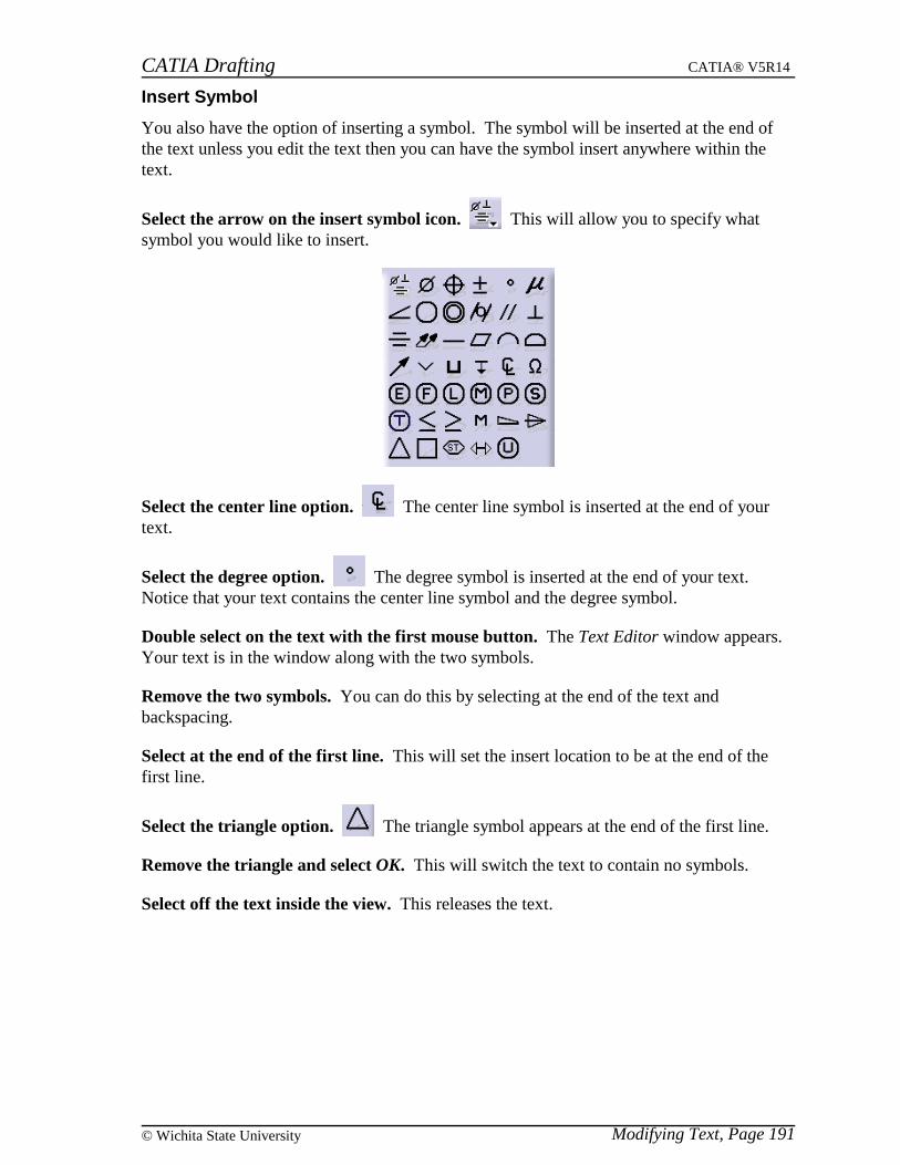
CATIA Drafting CATIA® V5R14
Modifying Text, Page 191© Wichita State University
Insert Symbol
You also have the option of inserting a symbol. The symbol will be inserted at the end ofthe text unless you edit the text then you can have the symbol insert anywhere within thetext.
Select the arrow on the insert symbol icon. This will allow you to specify whatsymbol you would like to insert.
Select the center line option. The center line symbol is inserted at the end of yourtext.
Select the degree option. The degree symbol is inserted at the end of your text.Notice that your text contains the center line symbol and the degree symbol.
Double select on the text with the first mouse button. The Text Editor window appears.Your text is in the window along with the two symbols.
Remove the two symbols. You can do this by selecting at the end of the text andbackspacing.
Select at the end of the first line. This will set the insert location to be at the end of thefirst line.
Select the triangle option. The triangle symbol appears at the end of the first line.
Remove the triangle and select OK. This will switch the text to contain no symbols.
Select off the text inside the view. This releases the text.
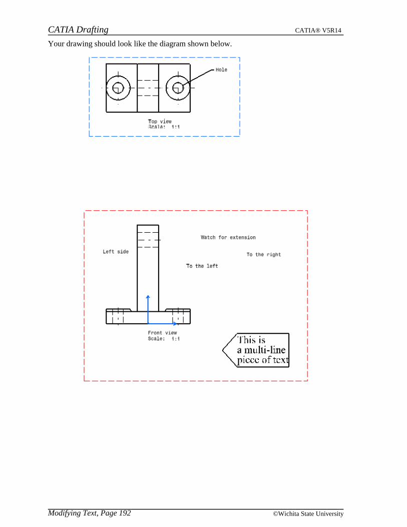
CATIA Drafting CATIA® V5R14
Modifying Text, Page 192 ©Wichita State University
Your drawing should look like the diagram shown below.

CATIA Drafting CATIA® V5R14
Modifying Text, Page 193© Wichita State University
Properties
You can also make changes to your text by changing the properties of the text.
Using the third mouse button go to Properties for the text Left side. The Propertieswindow appears with four different tabs available. The Font tab is shown below.
Font The type of font that is used
Style Controls whether the font is Italic, Bold, neither or both
Size Determines the size of the font
Underline Turn the underline option on or off
Color The color of the text
Attributes You can toggle on or off the Strikethrough, Overline, Superscript orSubscript options
Character You can adjust the Ratio, Slant, Spacing and Pitch of the text. The Ratiorefers to the size of the characters, Slant refers to the slant of the letters,Spacing refers to the space between characters and you can specify either aFixed or Variable Pitch.
Most of these options can be changed using the top toolbar as previously discussed.
Change the Spacing to be 20% and select Apply. Notice that the distance between letterschanged. You will now look at some of the other properties.
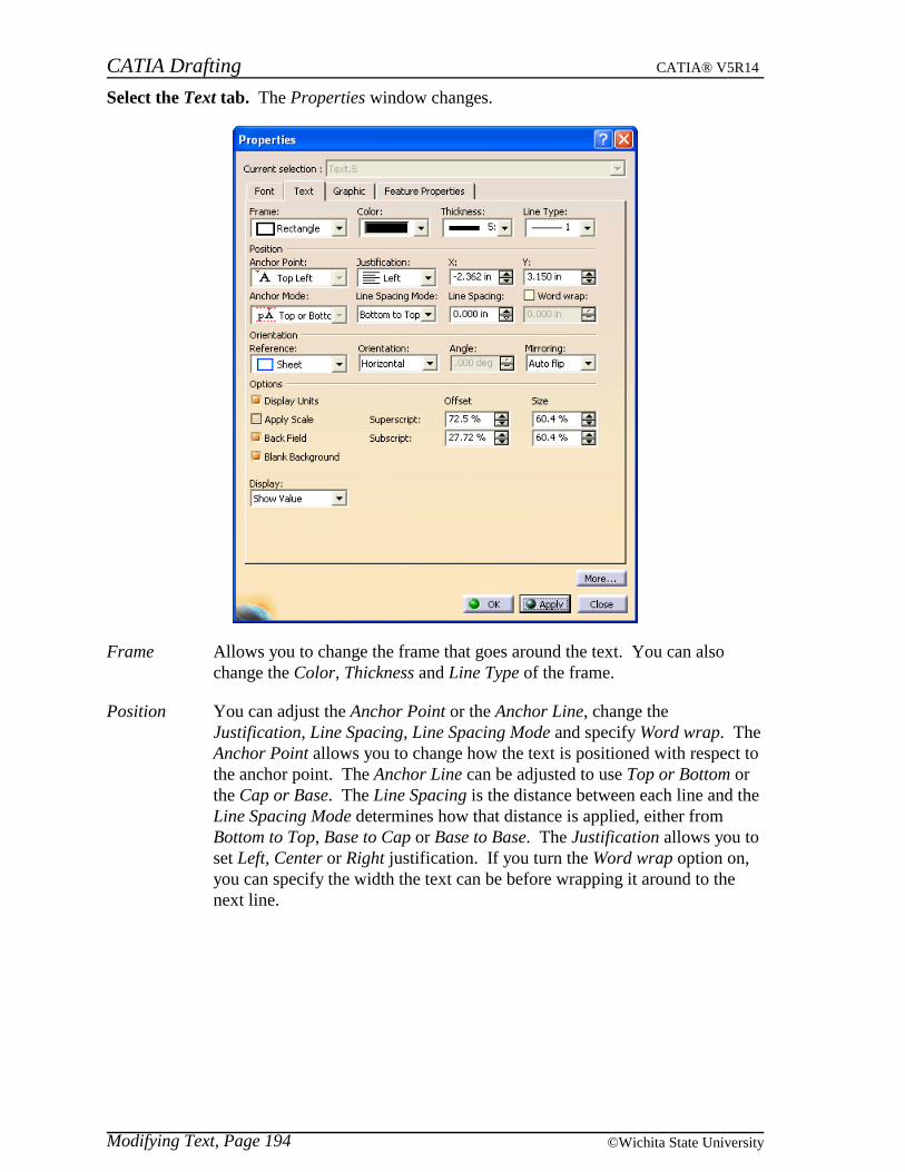
CATIA Drafting CATIA® V5R14
Modifying Text, Page 194 ©Wichita State University
Select the Text tab. The Properties window changes.
Frame Allows you to change the frame that goes around the text. You can alsochange the Color, Thickness and Line Type of the frame.
Position You can adjust the Anchor Point or the Anchor Line, change theJustification, Line Spacing, Line Spacing Mode and specify Word wrap. TheAnchor Point allows you to change how the text is positioned with respect tothe anchor point. The Anchor Line can be adjusted to use Top or Bottom orthe Cap or Base. The Line Spacing is the distance between each line and theLine Spacing Mode determines how that distance is applied, either fromBottom to Top, Base to Cap or Base to Base. The Justification allows you toset Left, Center or Right justification. If you turn the Word wrap option on,you can specify the width the text can be before wrapping it around to thenext line.

CATIA Drafting CATIA® V5R14
Modifying Text, Page 195© Wichita State University
Orientation You can set the Reference to be either the Sheet or the View and you canadjust the Orientation. The Orientation can be set to Horizontal, Vertical orFixed Angle. If you specify Fixed Angle then an Angle needs to be entered.The Mirroring option allows you to mirror your text. If you have the AutoFlip option on then the text will always be flipped to remain readable.
Options
Display Units If the text has parameters that have units, it will display thoseunits
Apply scale Toggles whether or not the text will scale with the view
Back Field Aligns superscript and subscript text
Blank Background Toggles whether or not the box area of the text blanks out anarea fill
Superscript/Subscript Allows you to adjust the offset and size of superscript andsubscript text
Display Specifies what display mode the text will have, it can either beset to Show Value, Show Box only, or Hide Value
A lot of those options can be adjusted using the top toolbar.
Change the frame to Rectangle and a Thickness of 5 and select Apply. The rectangleframe should appear around the text and it should be thick.
Change the Orientation to be Fixed Angle and change the Angle to be 30 and selectApply. The text should turn 30 degrees. You will now create some additional text to seesome of the other properties.
Select OK. The Properties window closes.
Create the following text above the geometry in the Front View. This is all one line oftext. It should read: This will show me some of the properties that are not as straightforward as some of the others. It should appear similar to the one shown below.
Using the third mouse button go to the Properties for this line of text.
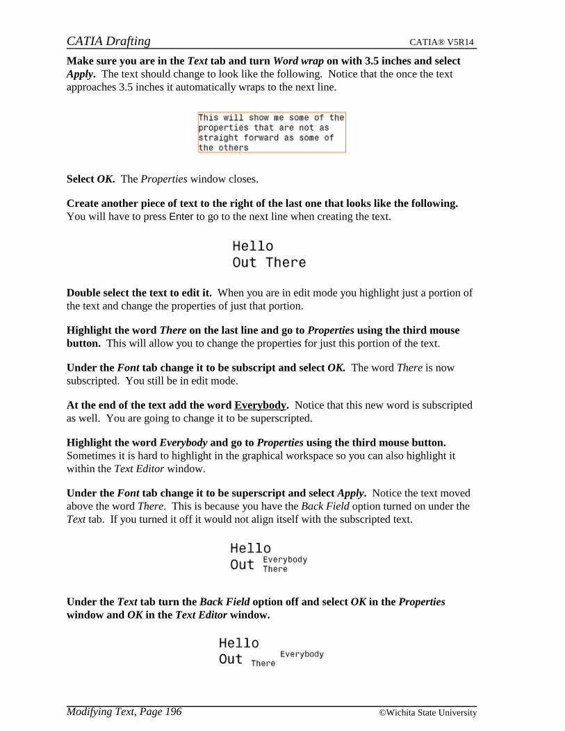
CATIA Drafting CATIA® V5R14
Modifying Text, Page 196 ©Wichita State University
Make sure you are in the Text tab and turn Word wrap on with 3.5 inches and selectApply. The text should change to look like the following. Notice that the once the textapproaches 3.5 inches it automatically wraps to the next line.
Select OK. The Properties window closes.
Create another piece of text to the right of the last one that looks like the following.You will have to press Enter to go to the next line when creating the text.
Double select the text to edit it. When you are in edit mode you highlight just a portion ofthe text and change the properties of just that portion.
Highlight the word There on the last line and go to Properties using the third mousebutton. This will allow you to change the properties for just this portion of the text.
Under the Font tab change it to be subscript and select OK. The word There is nowsubscripted. You still be in edit mode.
At the end of the text add the word Everybody. Notice that this new word is subscriptedas well. You are going to change it to be superscripted.
Highlight the word Everybody and go to Properties using the third mouse button.Sometimes it is hard to highlight in the graphical workspace so you can also highlight itwithin the Text Editor window.
Under the Font tab change it to be superscript and select Apply. Notice the text movedabove the word There. This is because you have the Back Field option turned on under theText tab. If you turned it off it would not align itself with the subscripted text.
Under the Text tab turn the Back Field option off and select OK in the Propertieswindow and OK in the Text Editor window.

CATIA Drafting CATIA® V5R14
Modifying Text, Page 197© Wichita State University
Using the third mouse button go to Properties for the leadered text Hole in the TopView.
Under the Text tab change the Display to be Show Box and select OK. Notice the text nolonger appears just a box representing it.
Go to the Properties again and change the Display to Hide Value and select OK. Noticenothing appears at the end of the leader line now.
Go to the Properties again and change the Display back to Show Value and select Apply.The text reappears.

CATIA Drafting CATIA® V5R14
Modifying Text, Page 198 ©Wichita State University
Select the Graphic tab. The Properties window changes.
Lines and Curves This applies to your frame. You also had these options underthe Text tab.
Show, Pick and Layers You can change what layer the text is on and whether it isPickable.
You are not going to change anything here.
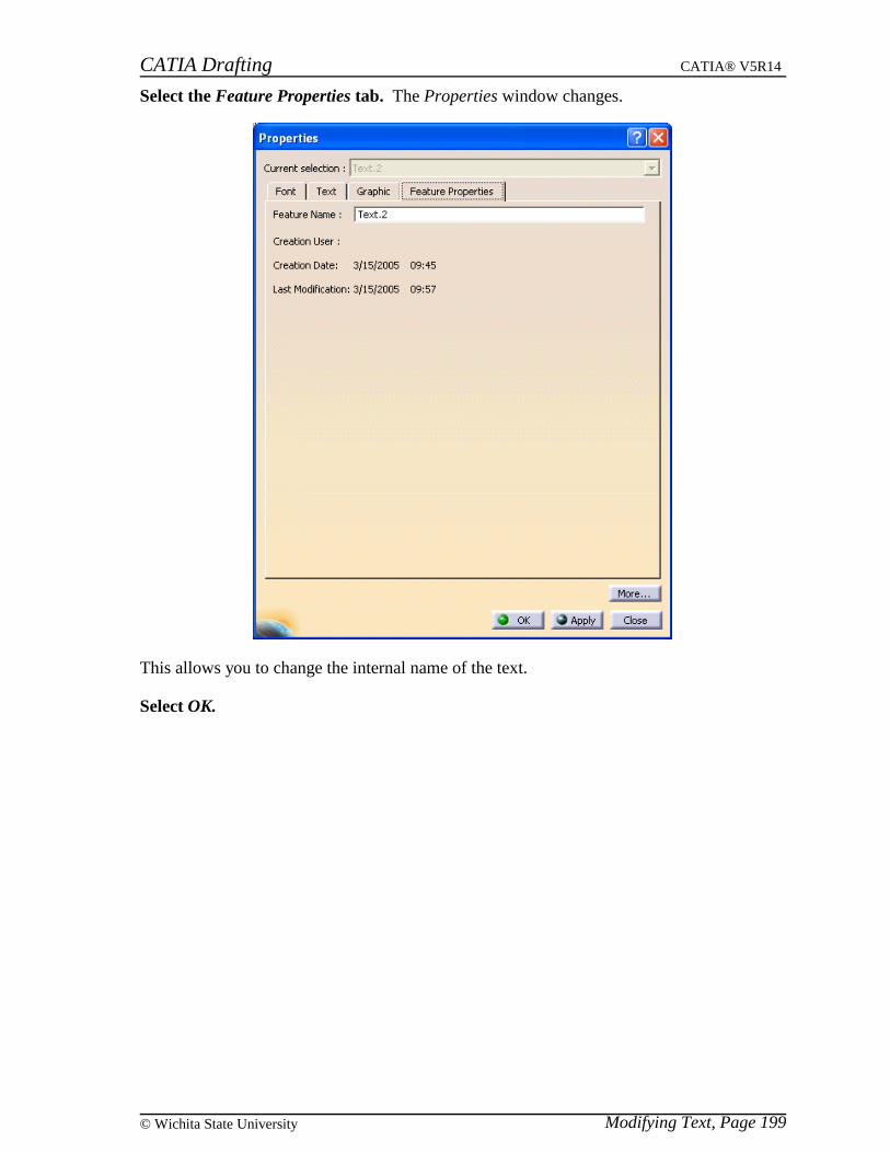
CATIA Drafting CATIA® V5R14
Modifying Text, Page 199© Wichita State University
Select the Feature Properties tab. The Properties window changes.
This allows you to change the internal name of the text.
Select OK.
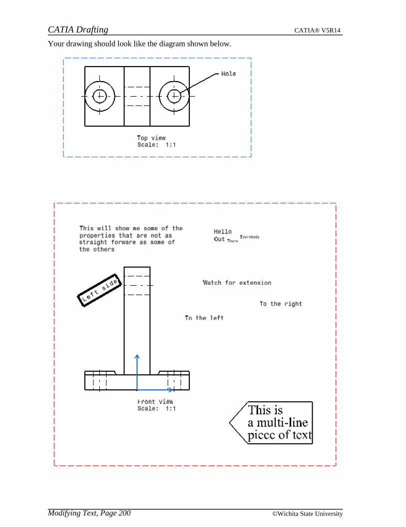
CATIA Drafting CATIA® V5R14
Modifying Text, Page 200 ©Wichita State University
Your drawing should look like the diagram shown below.
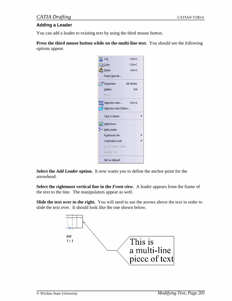
CATIA Drafting CATIA® V5R14
Modifying Text, Page 201© Wichita State University
Adding a Leader
You can add a leader to existing text by using the third mouse button.
Press the third mouse button while on the multi-line text. You should see the followingoptions appear.
Select the Add Leader option. It now wants you to define the anchor point for thearrowhead.
Select the rightmost vertical line in the Front view. A leader appears from the frame ofthe text to the line. The manipulators appear as well.
Slide the text over to the right. You will need to use the arrows above the text in order toslide the text over. It should look like the one shown below.
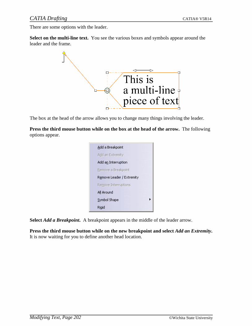
CATIA Drafting CATIA® V5R14
Modifying Text, Page 202 ©Wichita State University
There are some options with the leader.
Select on the multi-line text. You see the various boxes and symbols appear around theleader and the frame.
The box at the head of the arrow allows you to change many things involving the leader.
Press the third mouse button while on the box at the head of the arrow. The followingoptions appear.
Select Add a Breakpoint. A breakpoint appears in the middle of the leader arrow.
Press the third mouse button while on the new breakpoint and select Add an Extremity.It is now waiting for you to define another head location.
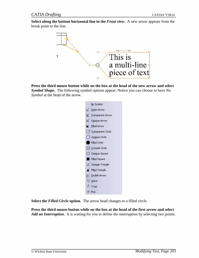
CATIA Drafting CATIA® V5R14
Modifying Text, Page 203© Wichita State University
Select along the bottom horizontal line in the Front view. A new arrow appears from thebreak point to the line.
Press the third mouse button while on the box at the head of the new arrow and selectSymbol Shape. The following symbol options appear. Notice you can choose to have NoSymbol at the head of the arrow.
Select the Filled Circle option. The arrow head changes to a filled circle.
Press the third mouse button while on the box at the head of the first arrow and selectAdd an Interruption. It is waiting for you to define the interruption by selecting two points.
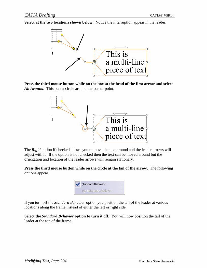
CATIA Drafting CATIA® V5R14
Modifying Text, Page 204 ©Wichita State University
Select at the two locations shown below. Notice the interruption appear in the leader.
Press the third mouse button while on the box at the head of the first arrow and selectAll Around. This puts a circle around the corner point.
The Rigid option if checked allows you to move the text around and the leader arrows willadjust with it. If the option is not checked then the text can be moved around but theorientation and location of the leader arrows will remain stationary.
Press the third mouse button while on the circle at the tail of the arrow. The followingoptions appear.
If you turn off the Standard Behavior option you position the tail of the leader at variouslocations along the frame instead of either the left or right side.
Select the Standard Behavior option to turn it off. You will now position the tail of theleader at the top of the frame.
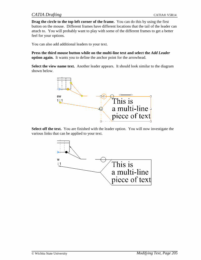
CATIA Drafting CATIA® V5R14
Modifying Text, Page 205© Wichita State University
Drag the circle to the top left corner of the frame. You can do this by using the firstbutton on the mouse. Different frames have different locations that the tail of the leader canattach to. You will probably want to play with some of the different frames to get a betterfeel for your options.
You can also add additional leaders to your text.
Press the third mouse button while on the multi-line text and select the Add Leaderoption again. It wants you to define the anchor point for the arrowhead.
Select the view name text. Another leader appears. It should look similar to the diagramshown below.
Select off the text. You are finished with the leader option. You will now investigate thevarious links that can be applied to your text.
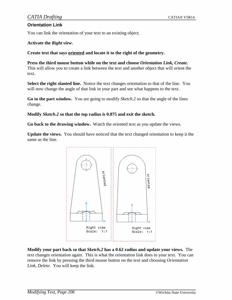
CATIA Drafting CATIA® V5R14
Modifying Text, Page 206 ©Wichita State University
Orientation Link
You can link the orientation of your text to an existing object.
Activate the Right view.
Create text that says oriented and locate it to the right of the geometry.
Press the third mouse button while on the text and choose Orientation Link, Create.This will allow you to create a link between the text and another object that will orient thetext.
Select the right slanted line. Notice the text changes orientation to that of the line. Youwill now change the angle of that link in your part and see what happens to the text.
Go to the part window. You are going to modify Sketch.2 so that the angle of the lineschange.
Modify Sketch.2 so that the top radius is 0.875 and exit the sketch.
Go back to the drawing window. Watch the oriented text as you update the views.
Update the views. You should have noticed that the text changed orientation to keep it thesame as the line.
Modify your part back so that Sketch.2 has a 0.62 radius and update your views. Thetext changes orientation again. This is what the orientation link does to your text. You canremove the link by pressing the third mouse button on the text and choosing OrientationLink, Delete. You will keep the link.
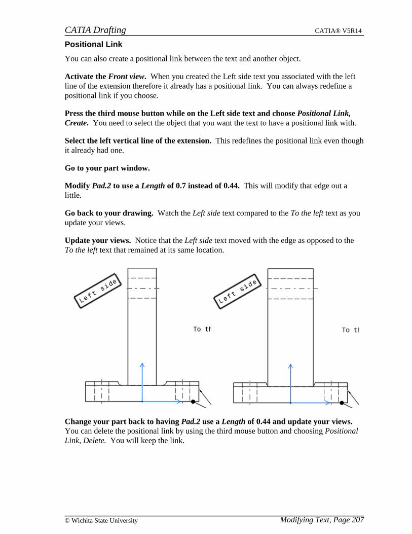
CATIA Drafting CATIA® V5R14
Modifying Text, Page 207© Wichita State University
Positional Link
You can also create a positional link between the text and another object.
Activate the Front view. When you created the Left side text you associated with the leftline of the extension therefore it already has a positional link. You can always redefine apositional link if you choose.
Press the third mouse button while on the Left side text and choose Positional Link,Create. You need to select the object that you want the text to have a positional link with.
Select the left vertical line of the extension. This redefines the positional link even thoughit already had one.
Go to your part window.
Modify Pad.2 to use a Length of 0.7 instead of 0.44. This will modify that edge out alittle.
Go back to your drawing. Watch the Left side text compared to the To the left text as youupdate your views.
Update your views. Notice that the Left side text moved with the edge as opposed to theTo the left text that remained at its same location.
Change your part back to having Pad.2 use a Length of 0.44 and update your views.You can delete the positional link by using the third mouse button and choosing PositionalLink, Delete. You will keep the link.
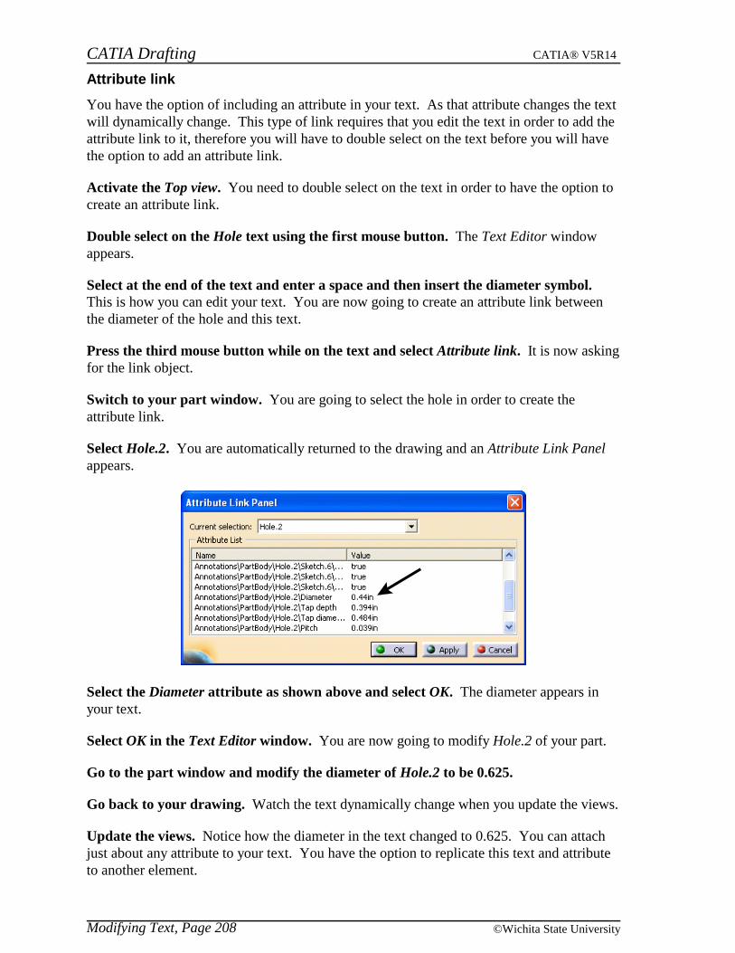
CATIA Drafting CATIA® V5R14
Modifying Text, Page 208 ©Wichita State University
Attribute link
You have the option of including an attribute in your text. As that attribute changes the textwill dynamically change. This type of link requires that you edit the text in order to add theattribute link to it, therefore you will have to double select on the text before you will havethe option to add an attribute link.
Activate the Top view. You need to double select on the text in order to have the option tocreate an attribute link.
Double select on the Hole text using the first mouse button. The Text Editor windowappears.
Select at the end of the text and enter a space and then insert the diameter symbol.This is how you can edit your text. You are now going to create an attribute link betweenthe diameter of the hole and this text.
Press the third mouse button while on the text and select Attribute link. It is now askingfor the link object.
Switch to your part window. You are going to select the hole in order to create theattribute link.
Select Hole.2. You are automatically returned to the drawing and an Attribute Link Panelappears.
Select the Diameter attribute as shown above and select OK. The diameter appears inyour text.
Select OK in the Text Editor window. You are now going to modify Hole.2 of your part.
Go to the part window and modify the diameter of Hole.2 to be 0.625.
Go back to your drawing. Watch the text dynamically change when you update the views.
Update the views. Notice how the diameter in the text changed to 0.625. You can attachjust about any attribute to your text. You have the option to replicate this text and attributeto another element.
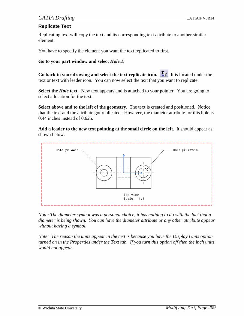
CATIA Drafting CATIA® V5R14
Modifying Text, Page 209© Wichita State University
Replicate Text
Replicating text will copy the text and its corresponding text attribute to another similarelement.
You have to specify the element you want the text replicated to first.
Go to your part window and select Hole.1.
Go back to your drawing and select the text replicate icon. It is located under thetext or text with leader icon. You can now select the text that you want to replicate.
Select the Hole text. New text appears and is attached to your pointer. You are going toselect a location for the text.
Select above and to the left of the geometry. The text is created and positioned. Noticethat the text and the attribute got replicated. However, the diameter attribute for this hole is0.44 inches instead of 0.625.
Add a leader to the new text pointing at the small circle on the left. It should appear asshown below.
Note: The diameter symbol was a personal choice, it has nothing to do with the fact that adiameter is being shown. You can have the diameter attribute or any other attribute appearwithout having a symbol.
Note: The reason the units appear in the text is because you have the Display Units optionturned on in the Properties under the Text tab. If you turn this option off then the inch unitswould not appear.

CATIA Drafting CATIA® V5R14
Modifying Text, Page 210 ©Wichita State University
Query Object Links
Query object links is used to determine what links are attached to a piece of text.
Press the third mouse button while on the 0.44 hole text and select Query ObjectLinks... A Query Link Panel window appears. You can see that there is an attribute linkwith Hole.1's diameter.
Select Close.
In the Front view press the third mouse button while on the Left side text and selectQuery Object Links... The Query Link Panel appears. Notice that there is just a positionallink.
Select the link from the window. The line that is associated with the positional linkhighlights in the Front view.
Select Close.
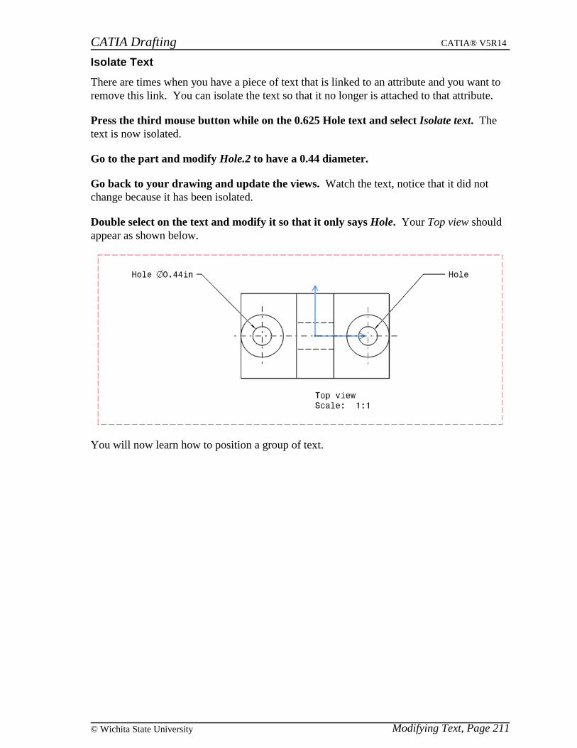
CATIA Drafting CATIA® V5R14
Modifying Text, Page 211© Wichita State University
Isolate Text
There are times when you have a piece of text that is linked to an attribute and you want toremove this link. You can isolate the text so that it no longer is attached to that attribute.
Press the third mouse button while on the 0.625 Hole text and select Isolate text. Thetext is now isolated.
Go to the part and modify Hole.2 to have a 0.44 diameter.
Go back to your drawing and update the views. Watch the text, notice that it did notchange because it has been isolated.
Double select on the text and modify it so that it only says Hole. Your Top view shouldappear as shown below.
You will now learn how to position a group of text.

CATIA Drafting CATIA® V5R14
Modifying Text, Page 212 ©Wichita State University
Element Positioning
Element positioning is used to position elements either by aligning them, spacing them apartor moving them as a group. This option can be used on more than just text, one example isviews. In order to see the icon you may have to use the pull down menu View, Toolbars andselect Positioning.
Activate the Front view.
Select the following text: Watch for extension, To the right and To the left. You willprobably have to use the Ctrl key.
Select the element positioning icon. The Positioning window appears.
Align These options align your elements vertically left, vertically centered,vertically right, horizontally top, horizontally centered or horizontally bottom
Space You can adjust the space between the elements either to the right, left, aboveor below
Distribute This will distribute the elements uniformly from left to right or from top tobottom
Move Moves the elements either horizontally or vertically
Select the align to left option. The three items of text align to the left.
Select the align to center option. The three items of text align centered vertically.
Select the distribute vertically option. This spaces your text evenly in the verticaldirection.
Select OK. This option is a quick method for positioning text or other elements.

CATIA Drafting CATIA® V5R14
Modifying Text, Page 213© Wichita State University
Tables
There are two icons available to put tables on your drawing. One option will create a tablefrom scratch and the other will allow you to import a table from a CSV file.
Make sure the Front view is activated.
Select the table icon. A Table Editor window appears. You can specify how manycolumns and rows you want the table to have.
Enter 4 for the Number of columns and 3 for the Number of rows and select OK. Youneed to specify the anchor point for the table.
Select to the right of the Watch for extension text. The table appears similar to the oneshown below. You have many options for modifying the table.
Double select on the table. The following framework appears around the table.
You can drag any of the column width sliders or the row height sliders to adjust the widthand height of columns and rows. You are going to perform other types of modificationsinstead.

CATIA Drafting CATIA® V5R14
Modifying Text, Page 214 ©Wichita State University
Double select inside the upper left cell of the table. This will open the Text Editorwindow.
Key in Upper left and select OK. The text appears in the table. This is how you can addtext inside the table.
Add the following text to the table. The table should look like the one shown below whenyou are finished.
Select the two upper middle cells. You can do this by holding down the first mouse buttonon the first cell and dragging the mouse over to the next cell.
Press the third mouse button. The following options appear.
Clear content Erases the content of the cells
Merge Merges the selected cells together
Unmerge Unmerges a cell that has been merged
Insert view Allows you to insert a view into the table
Select the Merge option. The table should look like the one shown below.
Select above the upper left cell. The entire column should be selected.

CATIA Drafting CATIA® V5R14
Modifying Text, Page 215© Wichita State University
Press the third mouse button. The following options appear.
Insert column Inserts a new column at that location
Delete Deletes the selected column from the table
Clear content Erases the contents of the cells in that column
Size
Set size The following window appears allowing you to specify the Columnwidth
Autofit Will make the column width big enough to contain the text that is inthe column
Select Size, Autofit. The column width adjusts to contain the Upper left text.
Select to the left of the lower left cell. The entire row should be selected.
Press the third mouse button. The following options appear.
You have the same options as with the column except they involve rows.
Select Delete. The row disappears. Your table should look like the one below.
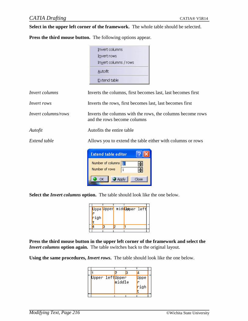
CATIA Drafting CATIA® V5R14
Modifying Text, Page 216 ©Wichita State University
Select in the upper left corner of the framework. The whole table should be selected.
Press the third mouse button. The following options appear.
Invert columns Inverts the columns, first becomes last, last becomes first
Invert rows Inverts the rows, first becomes last, last becomes first
Invert columns/rows Inverts the columns with the rows, the columns become rowsand the rows become columns
Autofit Autofits the entire table
Extend table Allows you to extend the table either with columns or rows
Select the Invert columns option. The table should look like the one below.
Press the third mouse button in the upper left corner of the framework and select theInvert columns option again. The table switches back to the original layout.
Using the same procedures, Invert rows. The table should look like the one below.
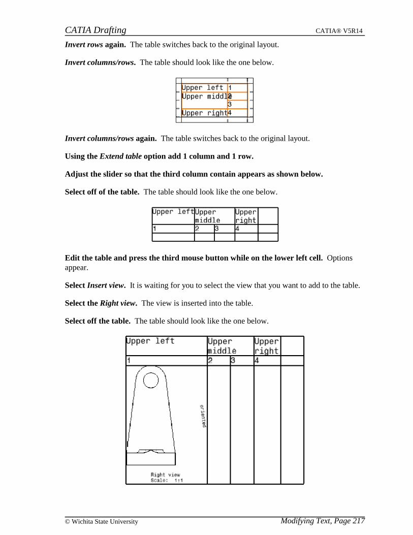
CATIA Drafting CATIA® V5R14
Modifying Text, Page 217© Wichita State University
Invert rows again. The table switches back to the original layout.
Invert columns/rows. The table should look like the one below.
Invert columns/rows again. The table switches back to the original layout.
Using the Extend table option add 1 column and 1 row.
Adjust the slider so that the third column contain appears as shown below.
Select off of the table. The table should look like the one below.
Edit the table and press the third mouse button while on the lower left cell. Optionsappear.
Select Insert view. It is waiting for you to select the view that you want to add to the table.
Select the Right view. The view is inserted into the table.
Select off the table. The table should look like the one below.
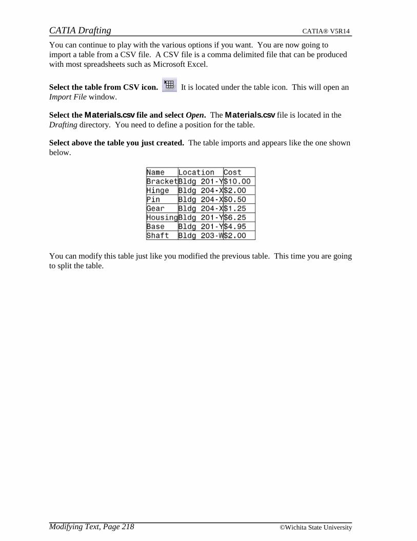
CATIA Drafting CATIA® V5R14
Modifying Text, Page 218 ©Wichita State University
You can continue to play with the various options if you want. You are now going toimport a table from a CSV file. A CSV file is a comma delimited file that can be producedwith most spreadsheets such as Microsoft Excel.
Select the table from CSV icon. It is located under the table icon. This will open anImport File window.
Select the Materials.csv file and select Open. The Materials.csv file is located in theDrafting directory. You need to define a position for the table.
Select above the table you just created. The table imports and appears like the one shownbelow.
You can modify this table just like you modified the previous table. This time you are goingto split the table.
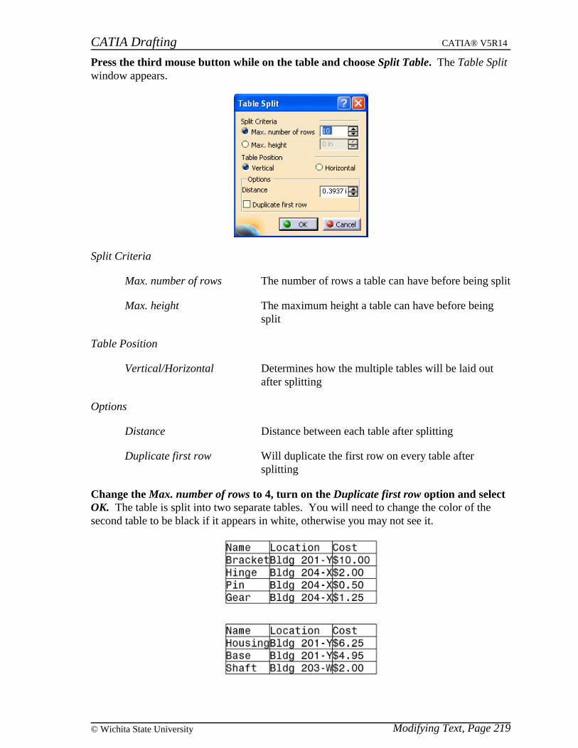
CATIA Drafting CATIA® V5R14
Modifying Text, Page 219© Wichita State University
Press the third mouse button while on the table and choose Split Table. The Table Splitwindow appears.
Split Criteria
Max. number of rows The number of rows a table can have before being split
Max. height The maximum height a table can have before beingsplit
Table Position
Vertical/Horizontal Determines how the multiple tables will be laid outafter splitting
Options
Distance Distance between each table after splitting
Duplicate first row Will duplicate the first row on every table aftersplitting
Change the Max. number of rows to 4, turn on the Duplicate first row option and selectOK. The table is split into two separate tables. You will need to change the color of thesecond table to be black if it appears in white, otherwise you may not see it.
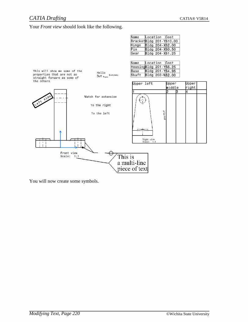
CATIA Drafting CATIA® V5R14
Modifying Text, Page 220 ©Wichita State University
Your Front view should look like the following.
You will now create some symbols.
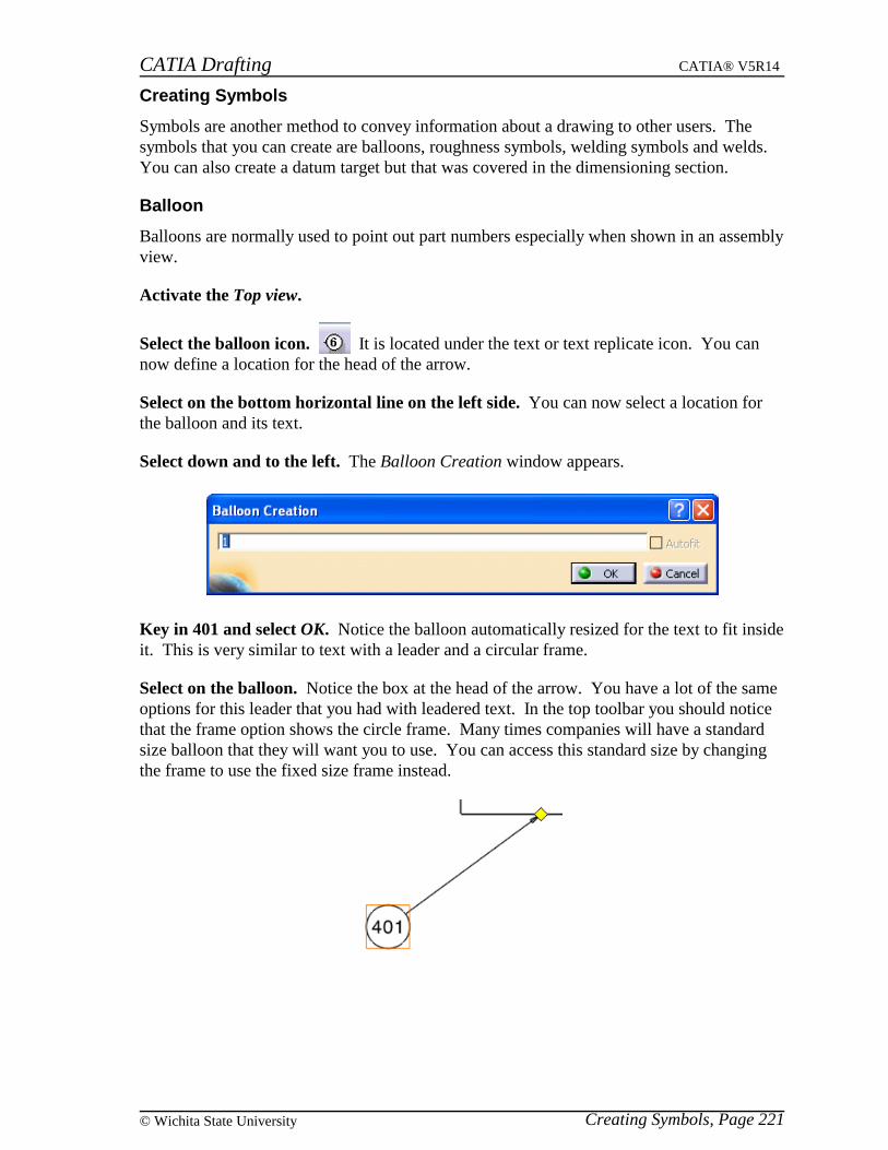
CATIA Drafting CATIA® V5R14
Creating Symbols, Page 221© Wichita State University
Creating Symbols
Symbols are another method to convey information about a drawing to other users. Thesymbols that you can create are balloons, roughness symbols, welding symbols and welds.You can also create a datum target but that was covered in the dimensioning section.
Balloon
Balloons are normally used to point out part numbers especially when shown in an assemblyview.
Activate the Top view.
Select the balloon icon. It is located under the text or text replicate icon. You cannow define a location for the head of the arrow.
Select on the bottom horizontal line on the left side. You can now select a location forthe balloon and its text.
Select down and to the left. The Balloon Creation window appears.
Key in 401 and select OK. Notice the balloon automatically resized for the text to fit insideit. This is very similar to text with a leader and a circular frame.
Select on the balloon. Notice the box at the head of the arrow. You have a lot of the sameoptions for this leader that you had with leadered text. In the top toolbar you should noticethat the frame option shows the circle frame. Many times companies will have a standardsize balloon that they will want you to use. You can access this standard size by changingthe frame to use the fixed size frame instead.

CATIA Drafting CATIA® V5R14
Creating Symbols, Page 222 ©Wichita State University
Using the icon in the top toolbar, change the frame to use the fixed size circle frame.This will be the one with the little lock on it.
Double select the balloon. The Balloon Modification window appears. Notice that theAutofit option is available now.
Select the Autofit option and select OK. The text inside the balloon automatically adjusteditself to fill the balloon.
Edit the text to be 12345 with the Autofit option on and select OK. The text is alwaysmade to fit within the balloon.
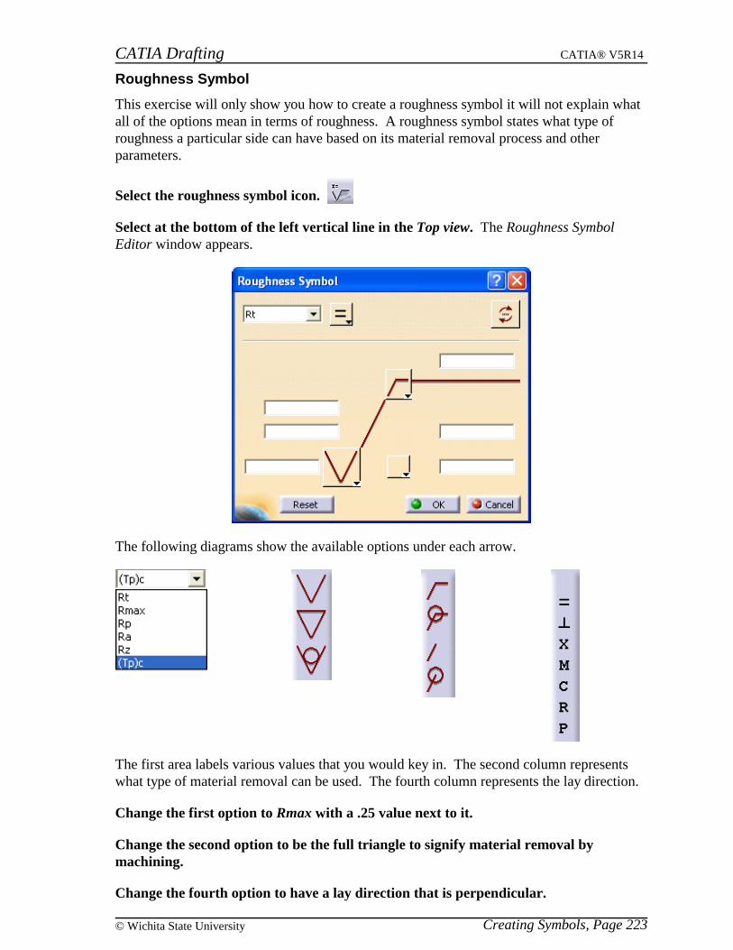
CATIA Drafting CATIA® V5R14
Creating Symbols, Page 223© Wichita State University
Roughness Symbol
This exercise will only show you how to create a roughness symbol it will not explain whatall of the options mean in terms of roughness. A roughness symbol states what type ofroughness a particular side can have based on its material removal process and otherparameters.
Select the roughness symbol icon.
Select at the bottom of the left vertical line in the Top view. The Roughness SymbolEditor window appears.
The following diagrams show the available options under each arrow.
The first area labels various values that you would key in. The second column representswhat type of material removal can be used. The fourth column represents the lay direction.
Change the first option to Rmax with a .25 value next to it.
Change the second option to be the full triangle to signify material removal bymachining.
Change the fourth option to have a lay direction that is perpendicular.
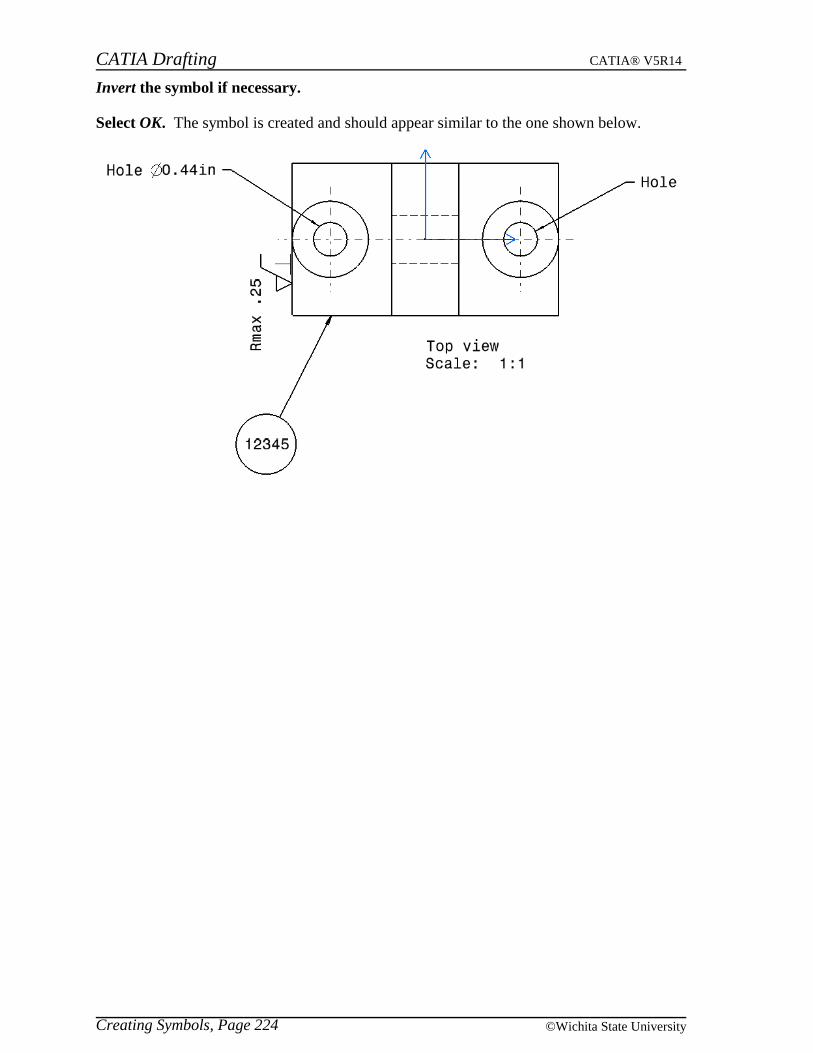
CATIA Drafting CATIA® V5R14
Creating Symbols, Page 224 ©Wichita State University
Invert the symbol if necessary.
Select OK. The symbol is created and should appear similar to the one shown below.
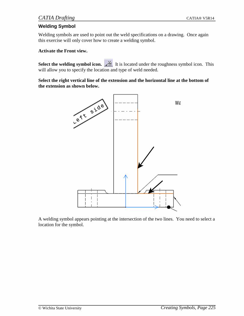
CATIA Drafting CATIA® V5R14
Creating Symbols, Page 225© Wichita State University
Welding Symbol
Welding symbols are used to point out the weld specifications on a drawing. Once againthis exercise will only cover how to create a welding symbol.
Activate the Front view.
Select the welding symbol icon. It is located under the roughness symbol icon. Thiswill allow you to specify the location and type of weld needed.
Select the right vertical line of the extension and the horizontal line at the bottom ofthe extension as shown below.
A welding symbol appears pointing at the intersection of the two lines. You need to select alocation for the symbol.
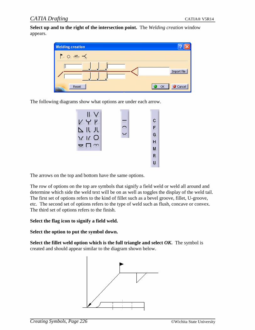
CATIA Drafting CATIA® V5R14
Creating Symbols, Page 226 ©Wichita State University
Select up and to the right of the intersection point. The Welding creation windowappears.
The following diagrams show what options are under each arrow.
The arrows on the top and bottom have the same options.
The row of options on the top are symbols that signify a field weld or weld all around anddetermine which side the weld text will be on as well as toggles the display of the weld tail.The first set of options refers to the kind of fillet such as a bevel groove, fillet, U-groove,etc. The second set of options refers to the type of weld such as flush, concave or convex.The third set of options refers to the finish.
Select the flag icon to signify a field weld.
Select the option to put the symbol down.
Select the fillet weld option which is the full triangle and select OK. The symbol iscreated and should appear similar to the diagram shown below.
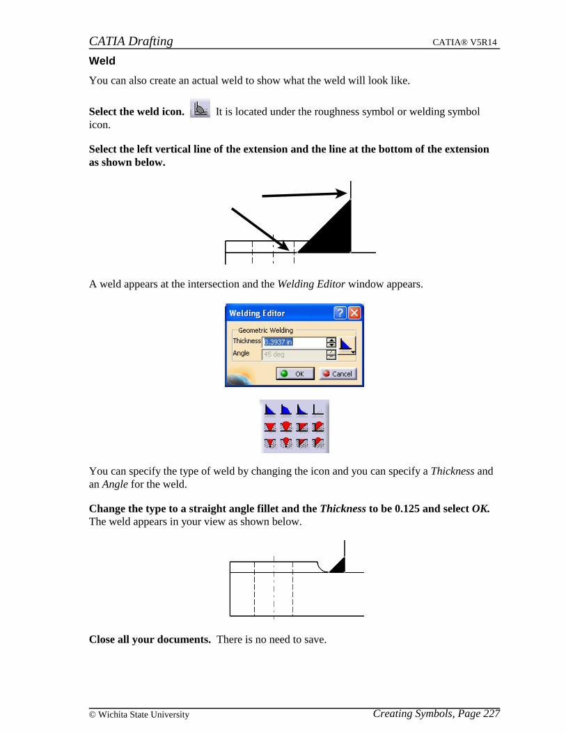
CATIA Drafting CATIA® V5R14
Creating Symbols, Page 227© Wichita State University
Weld
You can also create an actual weld to show what the weld will look like.
Select the weld icon. It is located under the roughness symbol or welding symbolicon.
Select the left vertical line of the extension and the line at the bottom of the extensionas shown below.
A weld appears at the intersection and the Welding Editor window appears.
You can specify the type of weld by changing the icon and you can specify a Thickness andan Angle for the weld.
Change the type to a straight angle fillet and the Thickness to be 0.125 and select OK.The weld appears in your view as shown below.
Close all your documents. There is no need to save.

CATIA Drafting CATIA® V5R14
Markup, Page 228 ©Wichita State University
Markup
These options are used to markup your drawing. A lot of these options can be generated bymodifying the properties of your view to show the respective elements. However, there maybe times that you want to manually create these markups. They are very useful when youare creating your drawings from scratch instead of having them be generated from 3D.
Center lines and Axis lines
Open the Markup drawing. You should see three views, one of them is a section view.Notice that there are not any center lines or axes shown in the views. You are going tomanually create them. These views are not linked to a part. The geometry is stand alone 2Dgeometry. You are going to provide the markups.
Zoom in on the Top view so that you can see the circles easier. You are going to createcenter lines.
Hide the section line. This will allow you to see the center lines better.
Select the center line icon. This will allow you to create center lines.
Select the larger circle on the right side. Center lines appear. You can adjust the lengthof them by selecting them and dragging one end of the center lines.
Select both of the smaller circles on the right and then select the center line icon.Notice that center lines are created on both circles automatically. You can also create centerlines that are associated to another element.
Select the center line with reference icon. It is located under the center line icon.This will allow you to create center lines that reference another element.
Select the larger circle on the left side. You can now select a reference.
Select the smaller circle in the middle. The center lines appear. Notice that the verticalcenter line is not actually a line but a curve since it is referencing the circle.
Select both of the smaller circles on the left and then select the center line withreference icon.
Select the smaller circle in the middle. The center lines appear on both circles referencingback to the center circle. You can also create thread notations on your circles.
Select the thread icon. It is located under the center line or center line with referenceicon. This will allow you to create a thread notation on a circle.
Select the smaller circle in the middle. The thread notation appears. Similar to the centerline option, you can create thread notations that reference another element as well.
Select the undo icon.
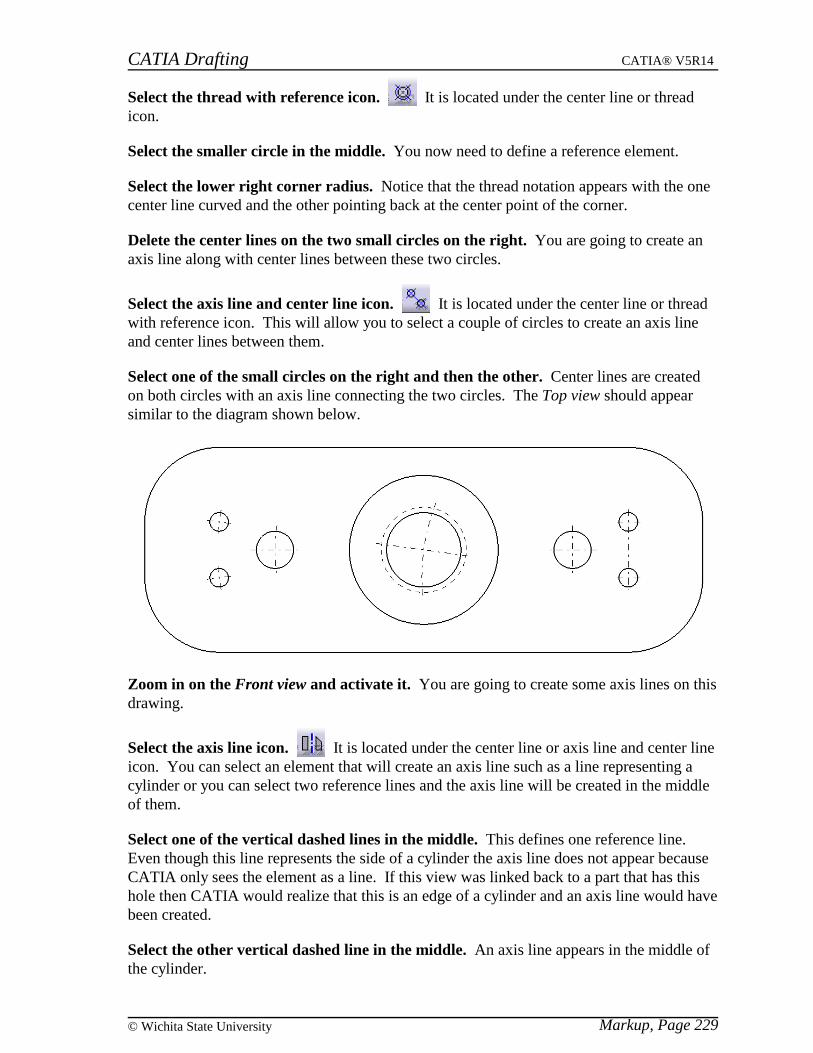
CATIA Drafting CATIA® V5R14
Markup, Page 229© Wichita State University
Select the thread with reference icon. It is located under the center line or threadicon.
Select the smaller circle in the middle. You now need to define a reference element.
Select the lower right corner radius. Notice that the thread notation appears with the onecenter line curved and the other pointing back at the center point of the corner.
Delete the center lines on the two small circles on the right. You are going to create anaxis line along with center lines between these two circles.
Select the axis line and center line icon. It is located under the center line or threadwith reference icon. This will allow you to select a couple of circles to create an axis lineand center lines between them.
Select one of the small circles on the right and then the other. Center lines are createdon both circles with an axis line connecting the two circles. The Top view should appearsimilar to the diagram shown below.
Zoom in on the Front view and activate it. You are going to create some axis lines on thisdrawing.
Select the axis line icon. It is located under the center line or axis line and center lineicon. You can select an element that will create an axis line such as a line representing acylinder or you can select two reference lines and the axis line will be created in the middleof them.
Select one of the vertical dashed lines in the middle. This defines one reference line.Even though this line represents the side of a cylinder the axis line does not appear becauseCATIA only sees the element as a line. If this view was linked back to a part that has thishole then CATIA would realize that this is an edge of a cylinder and an axis line would havebeen created.
Select the other vertical dashed line in the middle. An axis line appears in the middle ofthe cylinder.

CATIA Drafting CATIA® V5R14
Markup, Page 230 ©Wichita State University
Adjust the length to extend past the edges of the part. You can adjust the length byselecting on the line and then dragging one of the white boxes at the end of the line. If youonly want one of the ends to change then you need to hold the Ctrl key down when selectingthe white box.
Create axis lines in the center of all the rest of the holes by selecting the two lines thatrepresent the edges of the cylinder.
Adjust the length of these lines to extend past the edges of the part as shown below.
Activate the Top view.
Select the axis line icon.
Select the top right horizontal line and the bottom left horizontal line. An axis lineappears.
Adjust the size to go past the ends of the part. This is a good way to create a center lineon your drawing.
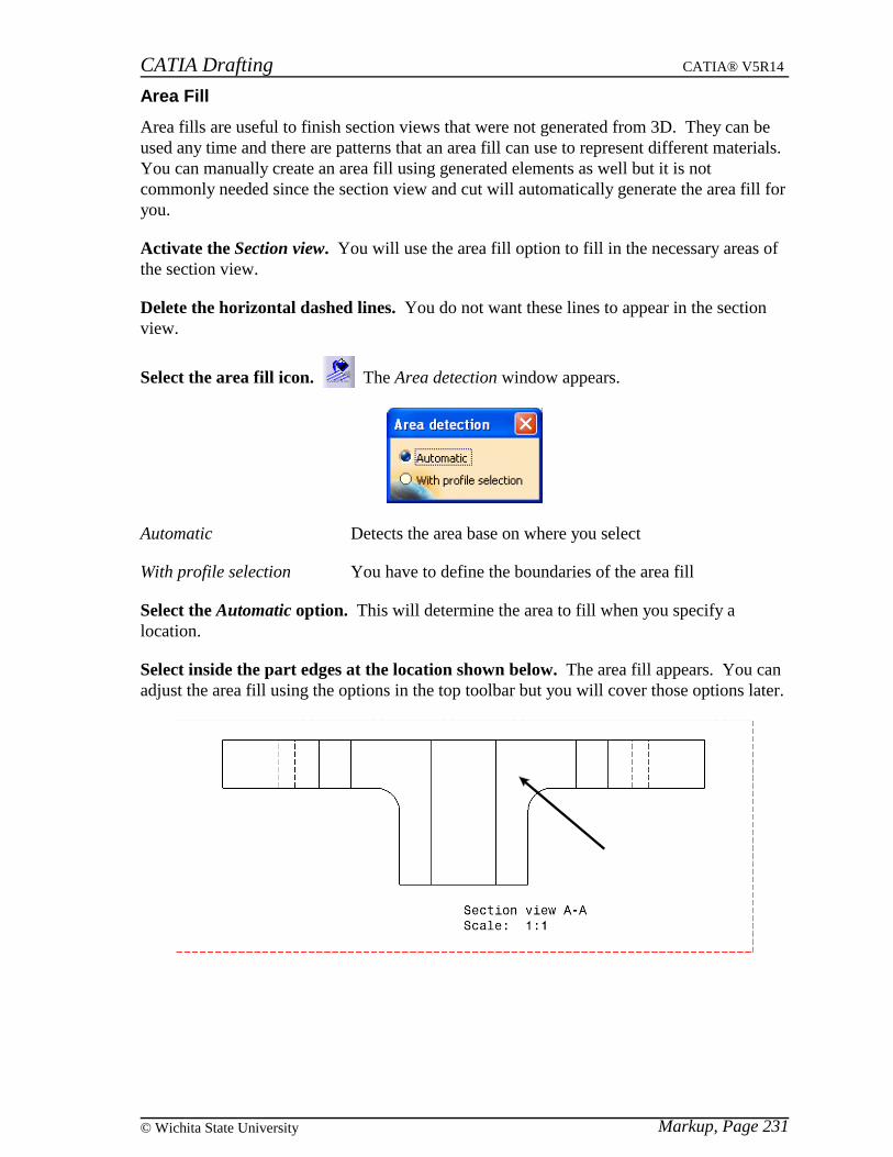
CATIA Drafting CATIA® V5R14
Markup, Page 231© Wichita State University
Area Fill
Area fills are useful to finish section views that were not generated from 3D. They can beused any time and there are patterns that an area fill can use to represent different materials.You can manually create an area fill using generated elements as well but it is notcommonly needed since the section view and cut will automatically generate the area fill foryou.
Activate the Section view. You will use the area fill option to fill in the necessary areas ofthe section view.
Delete the horizontal dashed lines. You do not want these lines to appear in the sectionview.
Select the area fill icon. The Area detection window appears.
Automatic Detects the area base on where you select
With profile selection You have to define the boundaries of the area fill
Select the Automatic option. This will determine the area to fill when you specify alocation.
Select inside the part edges at the location shown below. The area fill appears. You canadjust the area fill using the options in the top toolbar but you will cover those options later.
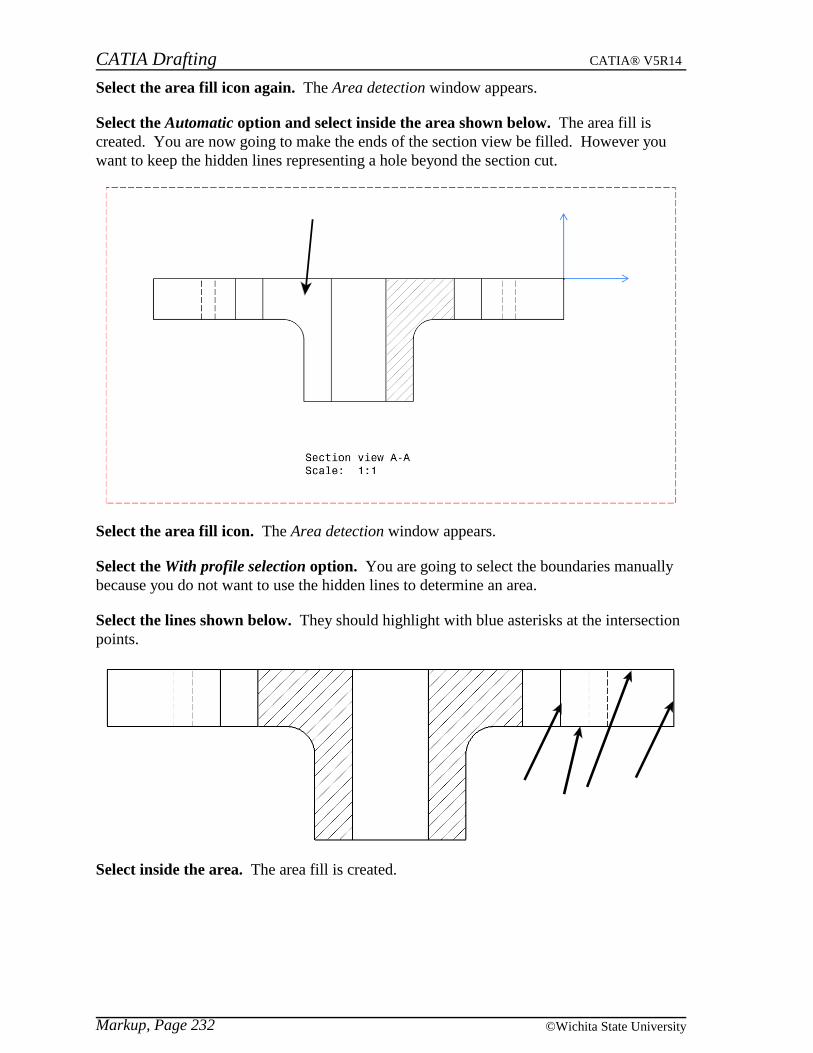
CATIA Drafting CATIA® V5R14
Markup, Page 232 ©Wichita State University
Select the area fill icon again. The Area detection window appears.
Select the Automatic option and select inside the area shown below. The area fill iscreated. You are now going to make the ends of the section view be filled. However youwant to keep the hidden lines representing a hole beyond the section cut.
Select the area fill icon. The Area detection window appears.
Select the With profile selection option. You are going to select the boundaries manuallybecause you do not want to use the hidden lines to determine an area.
Select the lines shown below. They should highlight with blue asterisks at the intersectionpoints.
Select inside the area. The area fill is created.
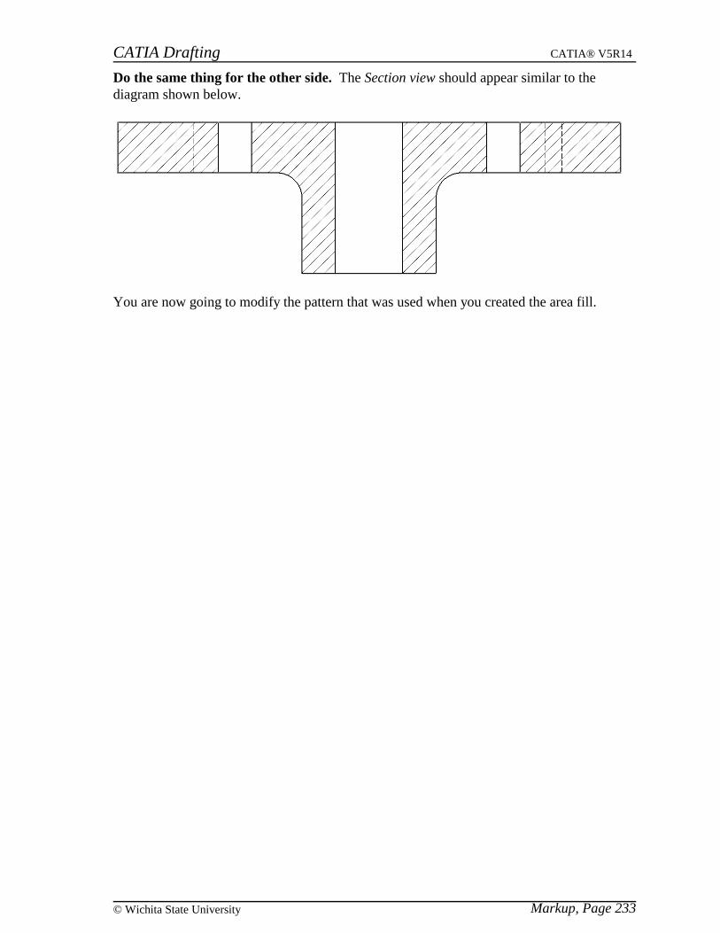
CATIA Drafting CATIA® V5R14
Markup, Page 233© Wichita State University
Do the same thing for the other side. The Section view should appear similar to thediagram shown below.
You are now going to modify the pattern that was used when you created the area fill.

CATIA Drafting CATIA® V5R14
Markup, Page 234 ©Wichita State University
Modifying an Area Fill
You can modify the pattern that an area fill uses as well as modifying the pattern that getsgenerated when you create a section view or cut from a 3D part. You can modify a patterneither by changing its properties or by using the top toolbar.
Properties
Make the Section view active. You are going to change the properties of the pattern.
Go to the properties of the pattern shown below. Remember you can go there by usingthe third mouse button.
The following Properties window corresponds to the properties of a pattern that wasmanually created not generated by a section view or cut of a 3D part. However, the onlydifference between this window and the other is a Material area which would appear at thebottom. Since an area fill that is created manually is not tied to a part then there is no needfor the Material area. If the pattern is generated from a 3D part then the pattern has thecapability to be linked to the material of the part.
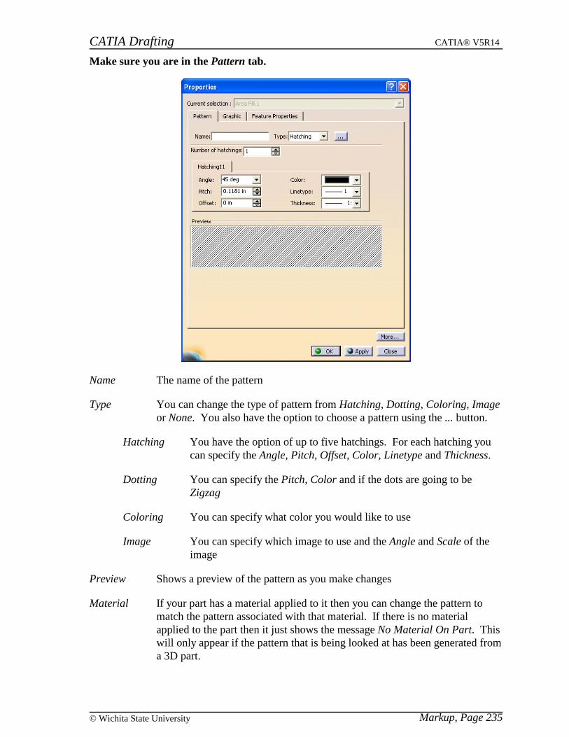
CATIA Drafting CATIA® V5R14
Markup, Page 235© Wichita State University
Make sure you are in the Pattern tab.
Name The name of the pattern
Type You can change the type of pattern from Hatching, Dotting, Coloring, Imageor None. You also have the option to choose a pattern using the ... button.
Hatching You have the option of up to five hatchings. For each hatching youcan specify the Angle, Pitch, Offset, Color, Linetype and Thickness.
Dotting You can specify the Pitch, Color and if the dots are going to beZigzag
Coloring You can specify what color you would like to use
Image You can specify which image to use and the Angle and Scale of theimage
Preview Shows a preview of the pattern as you make changes
Material If your part has a material applied to it then you can change the pattern tomatch the pattern associated with that material. If there is no materialapplied to the part then it just shows the message No Material On Part. Thiswill only appear if the pattern that is being looked at has been generated froma 3D part.

CATIA Drafting CATIA® V5R14
Markup, Page 236 ©Wichita State University
Under Hatching1 change the Angle to 30 degrees, Pitch to 0.08in and the Color to adark green and select Apply. Notice the preview changes as you make the changes and thepattern changes when you select Apply.
Select OK. Notice that the pattern only changes in the one area. The other area fills are notlinked to this one. You will now look at the options that are available in the top toolbar.
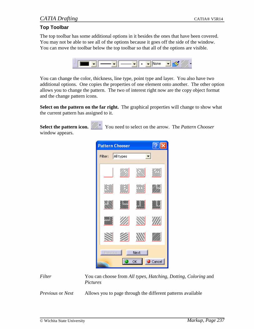
CATIA Drafting CATIA® V5R14
Markup, Page 237© Wichita State University
Top Toolbar
The top toolbar has some additional options in it besides the ones that have been covered.You may not be able to see all of the options because it goes off the side of the window.You can move the toolbar below the top toolbar so that all of the options are visible.
You can change the color, thickness, line type, point type and layer. You also have twoadditional options. One copies the properties of one element onto another. The other optionallows you to change the pattern. The two of interest right now are the copy object formatand the change pattern icons.
Select on the pattern on the far right. The graphical properties will change to show whatthe current pattern has assigned to it.
Select the pattern icon. You need to select on the arrow. The Pattern Chooserwindow appears.
Filter You can choose from All types, Hatching, Dotting, Coloring andPictures
Previous or Next Allows you to page through the different patterns available
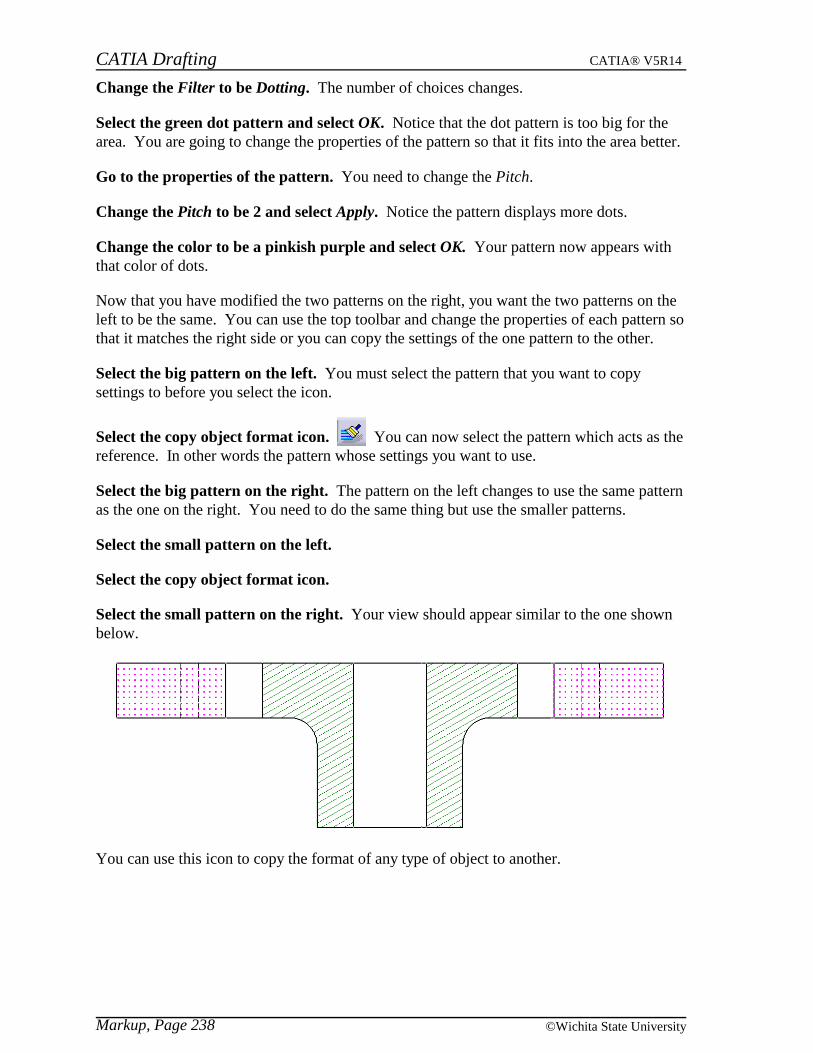
CATIA Drafting CATIA® V5R14
Markup, Page 238 ©Wichita State University
Change the Filter to be Dotting. The number of choices changes.
Select the green dot pattern and select OK. Notice that the dot pattern is too big for thearea. You are going to change the properties of the pattern so that it fits into the area better.
Go to the properties of the pattern. You need to change the Pitch.
Change the Pitch to be 2 and select Apply. Notice the pattern displays more dots.
Change the color to be a pinkish purple and select OK. Your pattern now appears withthat color of dots.
Now that you have modified the two patterns on the right, you want the two patterns on theleft to be the same. You can use the top toolbar and change the properties of each pattern sothat it matches the right side or you can copy the settings of the one pattern to the other.
Select the big pattern on the left. You must select the pattern that you want to copysettings to before you select the icon.
Select the copy object format icon. You can now select the pattern which acts as thereference. In other words the pattern whose settings you want to use.
Select the big pattern on the right. The pattern on the left changes to use the same patternas the one on the right. You need to do the same thing but use the smaller patterns.
Select the small pattern on the left.
Select the copy object format icon.
Select the small pattern on the right. Your view should appear similar to the one shownbelow.
You can use this icon to copy the format of any type of object to another.
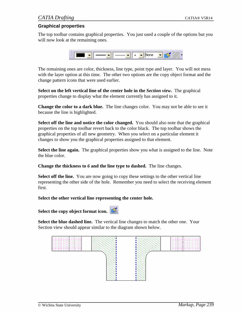
CATIA Drafting CATIA® V5R14
Markup, Page 239© Wichita State University
Graphical properties
The top toolbar contains graphical properties. You just used a couple of the options but youwill now look at the remaining ones.
The remaining ones are color, thickness, line type, point type and layer. You will not messwith the layer option at this time. The other two options are the copy object format and thechange pattern icons that were used earlier.
Select on the left vertical line of the center hole in the Section view. The graphicalproperties change to display what the element currently has assigned to it.
Change the color to a dark blue. The line changes color. You may not be able to see itbecause the line is highlighted.
Select off the line and notice the color changed. You should also note that the graphicalproperties on the top toolbar revert back to the color black. The top toolbar shows thegraphical properties of all new geometry. When you select on a particular element itchanges to show you the graphical properties assigned to that element.
Select the line again. The graphical properties show you what is assigned to the line. Notethe blue color.
Change the thickness to 6 and the line type to dashed. The line changes.
Select off the line. You are now going to copy these settings to the other vertical linerepresenting the other side of the hole. Remember you need to select the receiving elementfirst.
Select the other vertical line representing the center hole.
Select the copy object format icon.
Select the blue dashed line. The vertical line changes to match the other one. YourSection view should appear similar to the diagram shown below.
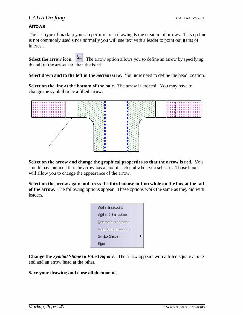
CATIA Drafting CATIA® V5R14
Markup, Page 240 ©Wichita State University
Arrows
The last type of markup you can perform on a drawing is the creation of arrows. This optionis not commonly used since normally you will use text with a leader to point out items ofinterest.
Select the arrow icon. The arrow option allows you to define an arrow by specifyingthe tail of the arrow and then the head.
Select down and to the left in the Section view. You now need to define the head location.
Select on the line at the bottom of the hole. The arrow is created. You may have tochange the symbol to be a filled arrow.
Select on the arrow and change the graphical properties so that the arrow is red. Youshould have noticed that the arrow has a box at each end when you select it. Those boxeswill allow you to change the appearance of the arrow.
Select on the arrow again and press the third mouse button while on the box at the tailof the arrow. The following options appear. These options work the same as they did withleaders.
Change the Symbol Shape to Filled Square. The arrow appears with a filled square at oneend and an arrow head at the other.
Save your drawing and close all documents.

CATIA Drafting CATIA® V5R14
Assembly, Page 241© Wichita State University
Assembly
You are going to create views using an assembly (product) as well as generate views of theparts that make up the assembly. You will be using a scene that was created, showing theexploded assembly and you will learn how to generate a bill of material within yourdrawing.
Creating an isometric view
Creating views for an assembly is not much different than creating views for a part.
Open the Views Assembly product from the Views Assembly directory. This is anassembly of a hand drill and it contains a scene of the part exploded.
Start a new drawing with an empty sheet, the settings should be ASME Standard, EANSI Sheet Style, Landscape orientation.
Change the windows to be Tiled Horizontally. You should be able to see the sheet and theproduct.
Select the isometric view icon and select the product anywhere. Notice the entireproduct is going to be used.
Create the view with the following orientation and change the scale to be 0.5. As youcan see it is not any different than creating an isometric view of a part.
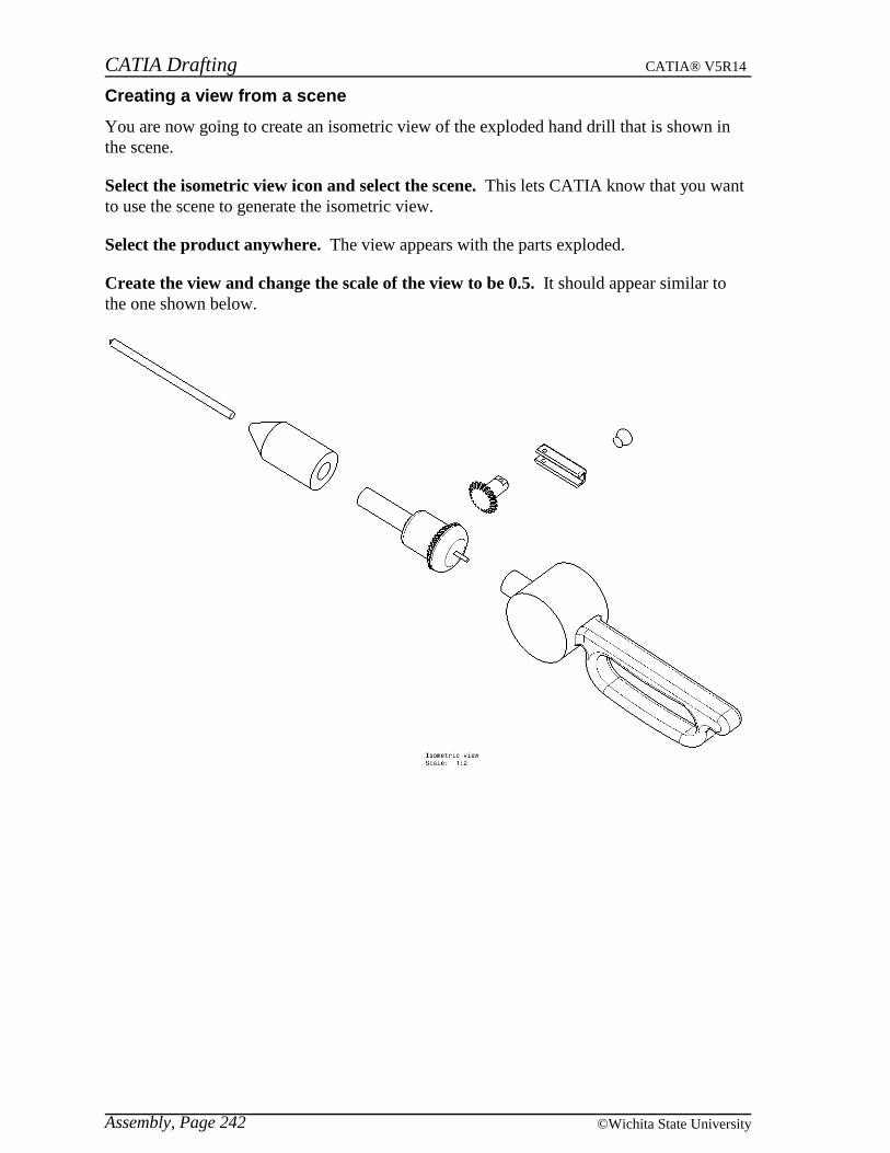
CATIA Drafting CATIA® V5R14
Assembly, Page 242 ©Wichita State University
Creating a view from a scene
You are now going to create an isometric view of the exploded hand drill that is shown inthe scene.
Select the isometric view icon and select the scene. This lets CATIA know that you wantto use the scene to generate the isometric view.
Select the product anywhere. The view appears with the parts exploded.
Create the view and change the scale of the view to be 0.5. It should appear similar tothe one shown below.

CATIA Drafting CATIA® V5R14
Assembly, Page 243© Wichita State University
Create another isometric of the hand drill not exploded but showing the other side andwith a scale of 0.5. Position the views to look similar to the diagram shown below.
Before you start making views of the individual parts you are going to want to generateballoons labeling each part and generate a bill of material on this sheet.
Activate the exploded view.

CATIA Drafting CATIA® V5R14
Assembly, Page 244 ©Wichita State University
Generate balloons
Select the generate balloons icon. It is located under the generating dimensions icon.Balloons appear on the view pointing at the individual parts. The reason they weregenerated is because in the product, numbering had been applied labeling them with letters.
Note: You can change what gets generated in the balloon under Tools, Options. In theMechanical Design, Drafting, Annotation and Dress-Up tab you can specify whether youwant to use the Numbering, Instance Name or Part Number. In this case you are using theNumbering.
Move the balloons around to look similar to the diagram shown below. Next you willgenerate a bill of material.
Note: There is an option under Tools, Options that will generate a balloon for eachinstance of a component. This option is in the Mechanical Design, Drafting, Generationtab. If this option is on then every instance of a component will get a balloon, if it is offthen only one instance of each part will get a balloon. This only applies when you have apart instanced multiple times within an assembly. If will not have an effect is this example.
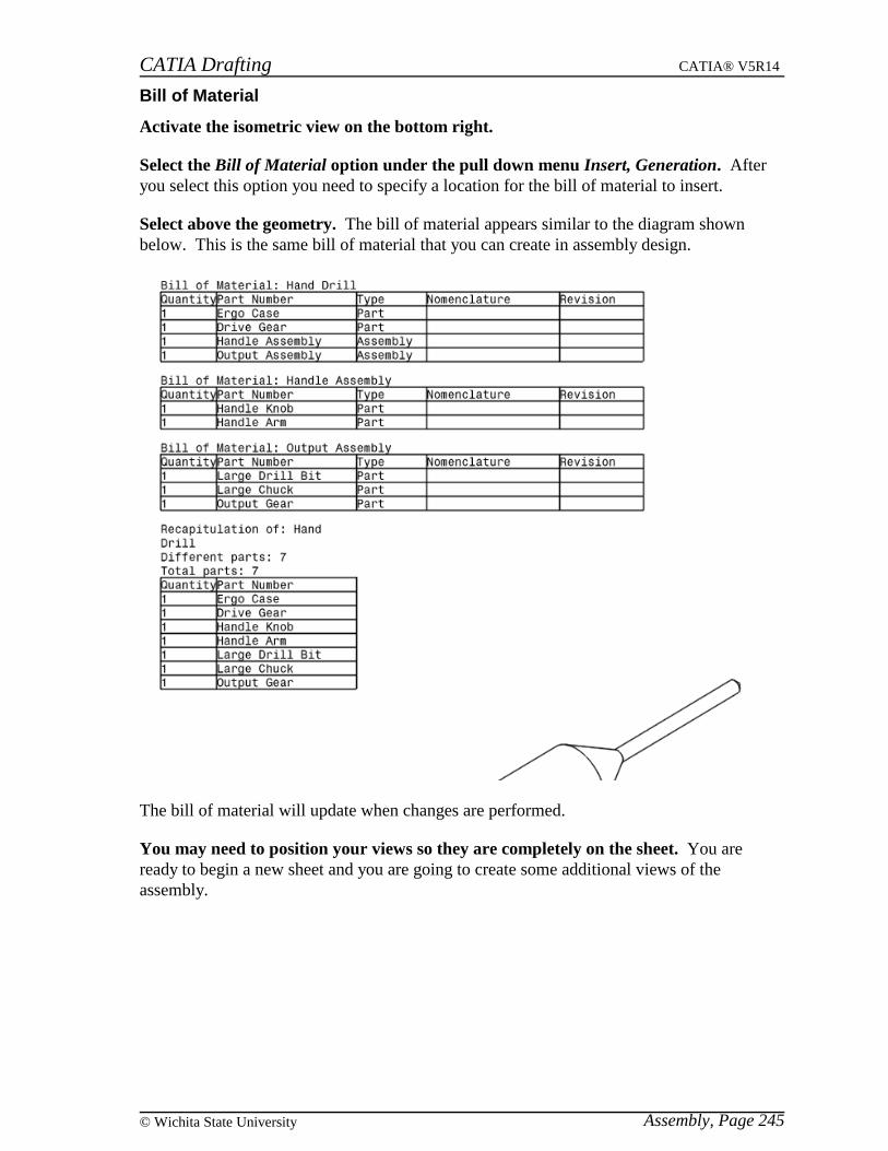
CATIA Drafting CATIA® V5R14
Assembly, Page 245© Wichita State University
Bill of Material
Activate the isometric view on the bottom right.
Select the Bill of Material option under the pull down menu Insert, Generation. Afteryou select this option you need to specify a location for the bill of material to insert.
Select above the geometry. The bill of material appears similar to the diagram shownbelow. This is the same bill of material that you can create in assembly design.
The bill of material will update when changes are performed.
You may need to position your views so they are completely on the sheet. You areready to begin a new sheet and you are going to create some additional views of theassembly.
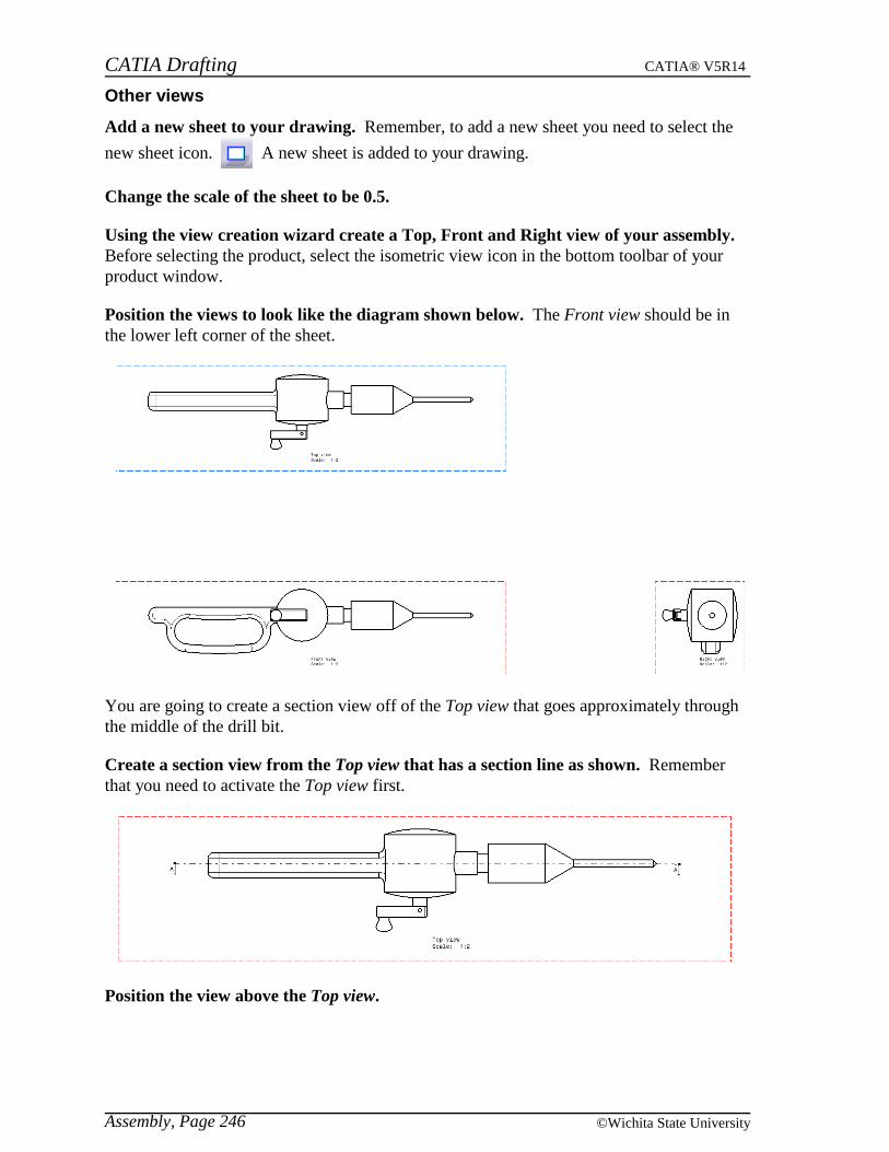
CATIA Drafting CATIA® V5R14
Assembly, Page 246 ©Wichita State University
Other views
Add a new sheet to your drawing. Remember, to add a new sheet you need to select the
new sheet icon. A new sheet is added to your drawing.
Change the scale of the sheet to be 0.5.
Using the view creation wizard create a Top, Front and Right view of your assembly.Before selecting the product, select the isometric view icon in the bottom toolbar of yourproduct window.
Position the views to look like the diagram shown below. The Front view should be inthe lower left corner of the sheet.
You are going to create a section view off of the Top view that goes approximately throughthe middle of the drill bit.
Create a section view from the Top view that has a section line as shown. Rememberthat you need to activate the Top view first.
Position the view above the Top view.

CATIA Drafting CATIA® V5R14
Assembly, Page 247© Wichita State University
The view should look similar to the one shown below.
Create a detail view as shown below. This view is created from the Top view. Youshould position the view to the right of the Top view.
Creating views of your assembly is really no different than creating views from a part. Youdo have a few options about how the parts of an assembly appear in a view. You canchange the properties of the part itself in the assembly window or you can set overloadproperties on the view.
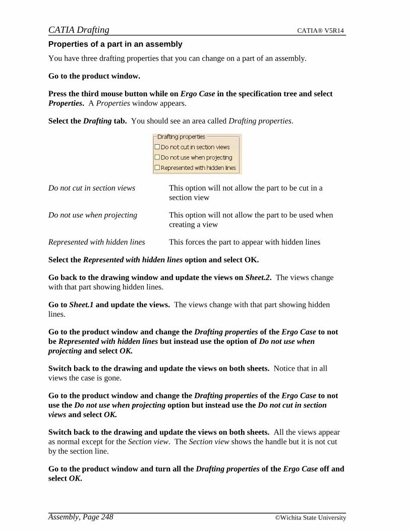
CATIA Drafting CATIA® V5R14
Assembly, Page 248 ©Wichita State University
Properties of a part in an assembly
You have three drafting properties that you can change on a part of an assembly.
Go to the product window.
Press the third mouse button while on Ergo Case in the specification tree and selectProperties. A Properties window appears.
Select the Drafting tab. You should see an area called Drafting properties.
Do not cut in section views This option will not allow the part to be cut in asection view
Do not use when projecting This option will not allow the part to be used whencreating a view
Represented with hidden lines This forces the part to appear with hidden lines
Select the Represented with hidden lines option and select OK.
Go back to the drawing window and update the views on Sheet.2. The views changewith that part showing hidden lines.
Go to Sheet.1 and update the views. The views change with that part showing hiddenlines.
Go to the product window and change the Drafting properties of the Ergo Case to notbe Represented with hidden lines but instead use the option of Do not use whenprojecting and select OK.
Switch back to the drawing and update the views on both sheets. Notice that in allviews the case is gone.
Go to the product window and change the Drafting properties of the Ergo Case to notuse the Do not use when projecting option but instead use the Do not cut in sectionviews and select OK.
Switch back to the drawing and update the views on both sheets. All the views appearas normal except for the Section view. The Section view shows the handle but it is not cutby the section line.
Go to the product window and turn all the Drafting properties of the Ergo Case off andselect OK.

CATIA Drafting CATIA® V5R14
Assembly, Page 249© Wichita State University
Switch back to the drawing and update the views on both sheets. The drawing shouldreturn to normal.
As you saw changing the properties of the part in the assembly is a good way of havingthose properties be used in multiple views but if you wanted some of those properties toonly occur in one of the views then you may have to use a different method. Next you willlook at changing the overload properties.

CATIA Drafting CATIA® V5R14
Assembly, Page 250 ©Wichita State University
Overload properties
The overload properties allows you to change how a particular part is shown or not shownin a view.
Make sure you are on Sheet.2 and press the third mouse button while on the Sectionview.
Select the Section view A-A object and then Overload Properties. A Characteristicswindow appears.
Select the gear in the Section view. The gear is shown below.
The Characteristics window changes.
Element Shows the instance name
Cut Will it be cut
Use Will it be used in projection
Hidden Lines Will it show hidden lines
Color, Line Type, Thickness The properties of the element in the view
Visibility Will you see the element
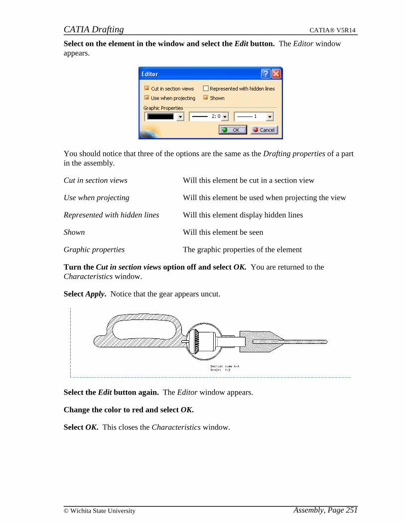
CATIA Drafting CATIA® V5R14
Assembly, Page 251© Wichita State University
Select on the element in the window and select the Edit button. The Editor windowappears.
You should notice that three of the options are the same as the Drafting properties of a partin the assembly.
Cut in section views Will this element be cut in a section view
Use when projecting Will this element be used when projecting the view
Represented with hidden lines Will this element display hidden lines
Shown Will this element be seen
Graphic properties The graphic properties of the element
Turn the Cut in section views option off and select OK. You are returned to theCharacteristics window.
Select Apply. Notice that the gear appears uncut.
Select the Edit button again. The Editor window appears.
Change the color to red and select OK.
Select OK. This closes the Characteristics window.
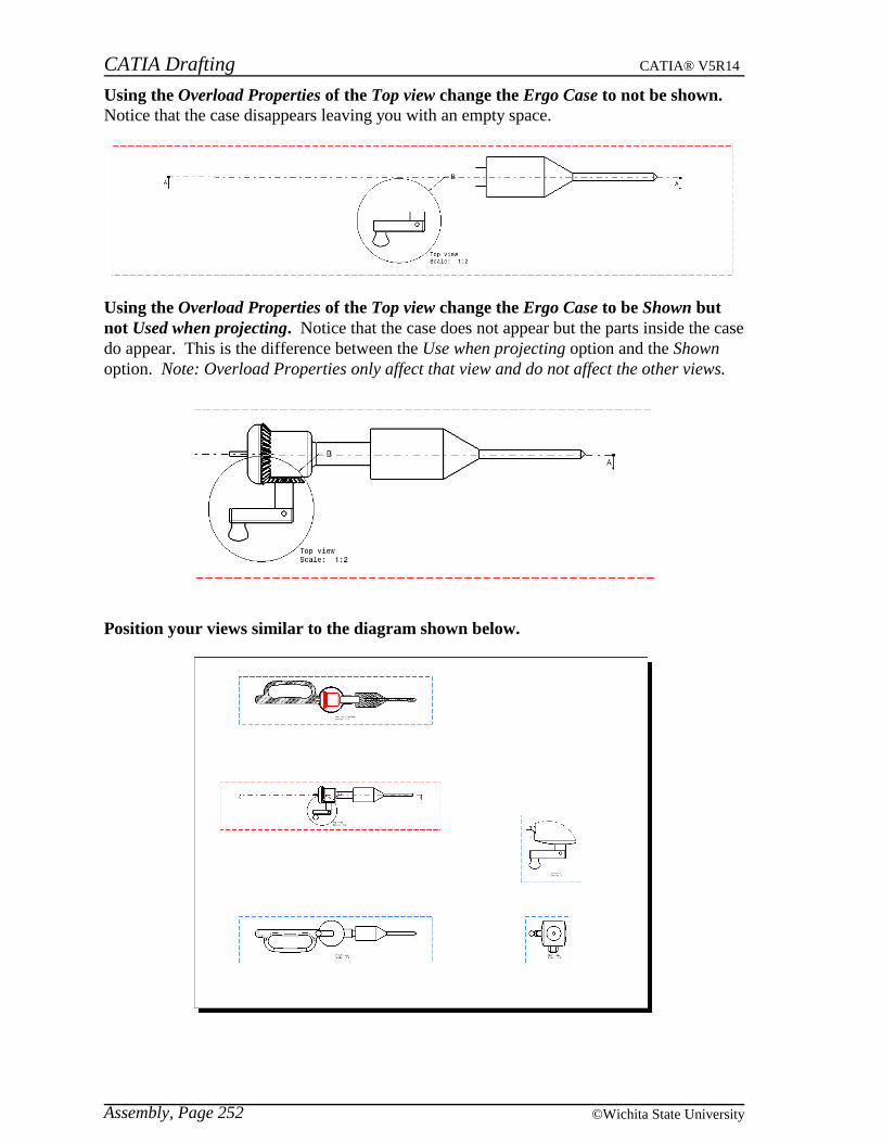
CATIA Drafting CATIA® V5R14
Assembly, Page 252 ©Wichita State University
Using the Overload Properties of the Top view change the Ergo Case to not be shown.Notice that the case disappears leaving you with an empty space.
Using the Overload Properties of the Top view change the Ergo Case to be Shown butnot Used when projecting. Notice that the case does not appear but the parts inside the casedo appear. This is the difference between the Use when projecting option and the Shownoption. Note: Overload Properties only affect that view and do not affect the other views.
Position your views similar to the diagram shown below.

CATIA Drafting CATIA® V5R14
Assembly, Page 253© Wichita State University
Cut, Copy and Paste views
You can cut, copy and paste views from one sheet to another. This is a quick method ofrearranging your views on a multiple sheet drawing.
Go to Sheet.1. You decide that you do not want both of the isometric views at the bottomof this sheet.
Press the third mouse button while on the bottom left isometric view and select Cut.The view disappears.
Move the remaining views as shown below.
Go to Sheet.2. This is so you can see what happens.
Press the third mouse button while on Sheet.2 in the specification tree and choosePaste. The isometric view appears on this sheet in the same place it was on Sheet.1.
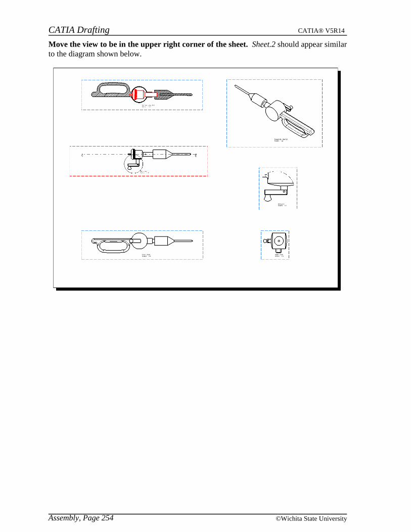
CATIA Drafting CATIA® V5R14
Assembly, Page 254 ©Wichita State University
Move the view to be in the upper right corner of the sheet. Sheet.2 should appear similarto the diagram shown below.

CATIA Drafting CATIA® V5R14
Assembly, Page 255© Wichita State University
Views of parts of an assembly
There may be times that you will want to create views of the various parts of an assemblyinstead of or in addition to the views of the assembly. This is easily done by selecting a partof the assembly instead of the complete assembly.
Insert a new sheet into your drawing. You are going to create views of the various partsof your assembly.
Change the scale to be 0.5.
Using the view creation wizard define a layout of Front, Top, Right. Before selectingthe part from the display area you will want to select the part from the tree.
Go to the product window.
Select Ergo Case from the specification tree. This will allow you to create views of thecase only.
Select on the side face of the case to define a plane.
Create the views and position them as shown below.
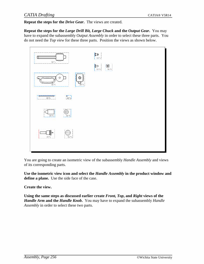
CATIA Drafting CATIA® V5R14
Assembly, Page 256 ©Wichita State University
Repeat the steps for the Drive Gear. The views are created.
Repeat the steps for the Large Drill Bit, Large Chuck and the Output Gear. You mayhave to expand the subassembly Output Assembly in order to select these three parts. Youdo not need the Top view for these three parts. Position the views as shown below.
You are going to create an isometric view of the subassembly Handle Assembly and viewsof its corresponding parts.
Use the isometric view icon and select the Handle Assembly in the product window anddefine a plane. Use the side face of the case.
Create the view.
Using the same steps as discussed earlier create Front, Top, and Right views of theHandle Arm and the Handle Knob. You may have to expand the subassembly HandleAssembly in order to select these two parts.
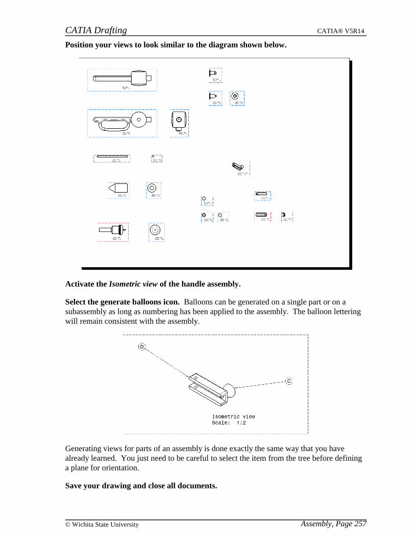
CATIA Drafting CATIA® V5R14
Assembly, Page 257© Wichita State University
Position your views to look similar to the diagram shown below.
Activate the Isometric view of the handle assembly.
Select the generate balloons icon. Balloons can be generated on a single part or on asubassembly as long as numbering has been applied to the assembly. The balloon letteringwill remain consistent with the assembly.
Generating views for parts of an assembly is done exactly the same way that you havealready learned. You just need to be careful to select the item from the tree before defininga plane for orientation.
Save your drawing and close all documents.

CATIA Drafting CATIA® V5R14
Assembly, Page 258 ©Wichita State University
View Links
Every view that is generated from a 3D document is linked to that document by default.Earlier you saw how you can make modifications to a 3D part and then update the views tosee the modifications take place on the drawing. You also were able to remove the link byisolating the view. When creating views using an assembly your views are linked to everyitem within that assembly by default. There are options that allow you to modify those linksand to even apply those links to other views.
Open the View Links document and drawing located in the View Links directory.
Press the third mouse button while on the Front view and select Front view object,Modify Links. The Link Modification window appears. By default the view is pointed tothe whole assembly.
Switch to the product window. You are going to select the components that you want theview to be linked with.
Select each item except for the pins. You will have to use the Ctrl key in order to selectmultiple components.
Go back to the drawing window. Notice that the window has the option to Add all.
Select the Add all button. The selected components are added to the Pointed elementsarea.

CATIA Drafting CATIA® V5R14
Assembly, Page 259© Wichita State University
Select Preview. The window shows a preview of the pointed elements.
Select the two fixtures from the window and select the Remove button. You will haveto use the Ctrl key to select both of them at once.
Select OK and update the views. The front view no longer shows the fixtures or the pins.
Press the third mouse button while on the Front view and select Query Object Links.The Query Link Panel appears. Notice that all of the individual parts are linked to the view.
Select Close.
Query the object links on the Isometric view. Notice that is just shows a link to theproduct itself since it is using the entire assembly.
Select Close.
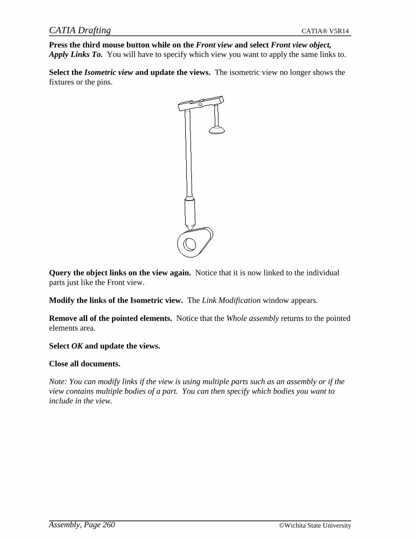
CATIA Drafting CATIA® V5R14
Assembly, Page 260 ©Wichita State University
Press the third mouse button while on the Front view and select Front view object,Apply Links To. You will have to specify which view you want to apply the same links to.
Select the Isometric view and update the views. The isometric view no longer shows thefixtures or the pins.
Query the object links on the view again. Notice that it is now linked to the individualparts just like the Front view.
Modify the links of the Isometric view. The Link Modification window appears.
Remove all of the pointed elements. Notice that the Whole assembly returns to the pointedelements area.
Select OK and update the views.
Close all documents.
Note: You can modify links if the view is using multiple parts such as an assembly or if theview contains multiple bodies of a part. You can then specify which bodies you want toinclude in the view.

CATIA Drafting CATIA® V5R14
2D Geometry, Page 261© Wichita State University
2D Geometry
Besides generating geometry from a 3D part or product, you can also create 2D geometrymanually. This geometry is commonly used for defining elements that aid in dimensioningand to build title blocks. Of course once your company has defined their title blocks you donot need to create your own. You also have the option of creating 2D views without havinga 3D part or product. This is usually referred to as interactive drafting.
Creating a view
When you are going to create your own views without using a 3D part or product you needto create a view that the geometry will exist in. This is easily done.
Start a new drawing with an empty sheet, the settings should be ASME Standard, CANSI Sheet Style, Landscape orientation.
Select the new view icon. You need to specify a location.
Select in the lower left corner of the sheet. A new view is created with no geometry.
Drawing tools
The drawing tools are identical to your sketcher tools. They are reorganized a littledifferently but you have the same options. One exception is that you only have a constraintby dialog icon. You do not have the constraint icon. This is okay because you usedimensions to constrain your geometry. You do need to change the dimensions to bedriving dimensions.
Select the profile icon.
Create the following profile. Notice that no constraints were generated as you created thisprofile.
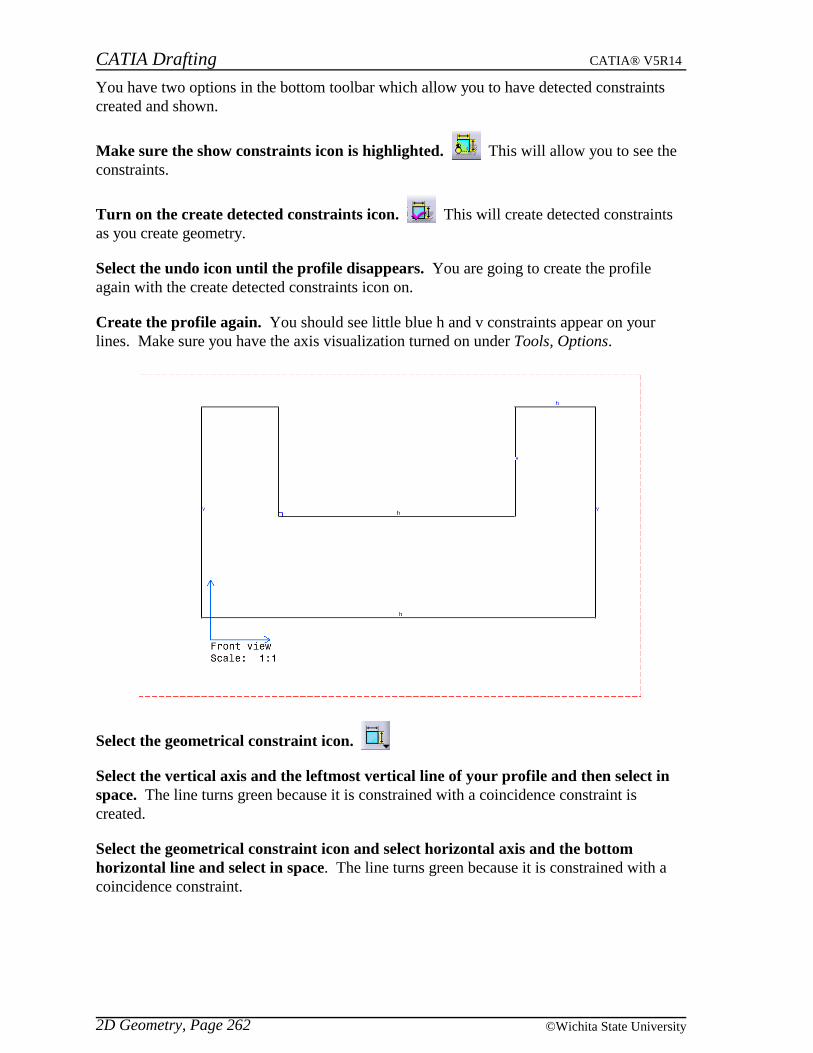
CATIA Drafting CATIA® V5R14
2D Geometry, Page 262 ©Wichita State University
You have two options in the bottom toolbar which allow you to have detected constraintscreated and shown.
Make sure the show constraints icon is highlighted. This will allow you to see theconstraints.
Turn on the create detected constraints icon. This will create detected constraintsas you create geometry.
Select the undo icon until the profile disappears. You are going to create the profileagain with the create detected constraints icon on.
Create the profile again. You should see little blue h and v constraints appear on yourlines. Make sure you have the axis visualization turned on under Tools, Options.
Select the geometrical constraint icon.
Select the vertical axis and the leftmost vertical line of your profile and then select inspace. The line turns green because it is constrained with a coincidence constraint iscreated.
Select the geometrical constraint icon and select horizontal axis and the bottomhorizontal line and select in space. The line turns green because it is constrained with acoincidence constraint.

CATIA Drafting CATIA® V5R14
2D Geometry, Page 263© Wichita State University
Select the dimensions icon. This icon is used the same way you used it earlier tocreate dimensions.
Make sure you are numeric standard is set to NUM.DINC.
Select the bottom horizontal line and the top left horizontal line and position thedimension. A dimension appears. Notice the top line did not turn green because this is justa dimension not a constraint. You need to make this dimension a driving dimension inorder to make it act like a constraint.
Double select on the dimension with the first mouse button. A Dimension Valuewindow appears.
Select the Drive geometry option and change the value to be 4.5 and select OK. If youselect off the dimension you will notice that it is a blue color representing a drivingdimension. The top left horizontal line is constrained. Since you are going to be creating alot of these driving dimensions you will want to set it up so they are created on the fly.
Go to pull down menu Tools, Options, Mechanical Design, Drafting, Dimension andturn on the Create driving dimension option and select OK. This will set it up so thatwhen you create a dimension it is automatically a driving dimension. This is normally thesetting you will want to use when constraining 2D geometry.
Create the remaining constraints as shown below. The top two horizontal lines have acoincidence applied between them.
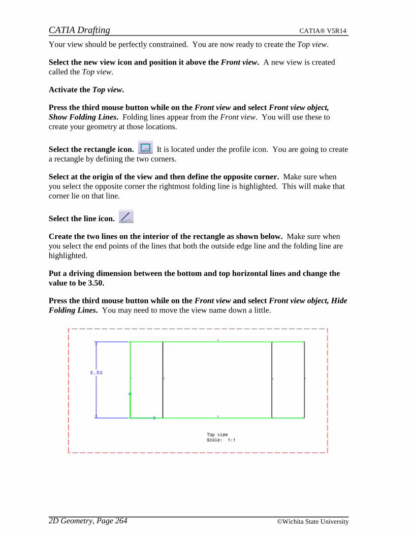
CATIA Drafting CATIA® V5R14
2D Geometry, Page 264 ©Wichita State University
Your view should be perfectly constrained. You are now ready to create the Top view.
Select the new view icon and position it above the Front view. A new view is createdcalled the Top view.
Activate the Top view.
Press the third mouse button while on the Front view and select Front view object,Show Folding Lines. Folding lines appear from the Front view. You will use these tocreate your geometry at those locations.
Select the rectangle icon. It is located under the profile icon. You are going to createa rectangle by defining the two corners.
Select at the origin of the view and then define the opposite corner. Make sure whenyou select the opposite corner the rightmost folding line is highlighted. This will make thatcorner lie on that line.
Select the line icon.
Create the two lines on the interior of the rectangle as shown below. Make sure whenyou select the end points of the lines that both the outside edge line and the folding line arehighlighted.
Put a driving dimension between the bottom and top horizontal lines and change thevalue to be 3.50.
Press the third mouse button while on the Front view and select Front view object, HideFolding Lines. You may need to move the view name down a little.

CATIA Drafting CATIA® V5R14
2D Geometry, Page 265© Wichita State University
I know this seems like a pain and it is. CATIA is designed to be a 3D package and thereforethe 2D only tools are not the best in the world. Luckily you do not need to use these optionsvery often. You are almost done doing views manually.
Create a new view and position it to the right and in between the two existing views. Itis called an Isometric view.
Activate the view.
View plane definition
Select the view plane definition icon. You can find this icon by turning on the MultiView (2.5D) toolbar using pull down menu View, Toolbars. You can also select the ViewPlane Definition option under the pull down menu Tools, Multi View(2.5D). The ViewPlane window appears.
You can play with the different options on your own. This determines the axis orientationfor the new view. You can use this option on any new view to create auxiliary views orisometric views.
Select the ZXY axis in the middle of the top row and select OK. This orients the view tobe in an isometric orientation. You will not notice until you start projecting geometry.
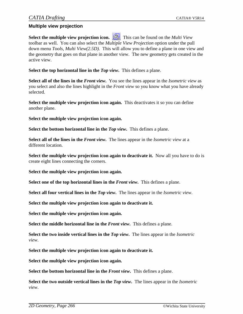
CATIA Drafting CATIA® V5R14
2D Geometry, Page 266 ©Wichita State University
Multiple view projection
Select the multiple view projection icon. This can be found on the Multi Viewtoolbar as well. You can also select the Multiple View Projection option under the pulldown menu Tools, Multi View(2.5D). This will allow you to define a plane in one view andthe geometry that goes on that plane in another view. The new geometry gets created in theactive view.
Select the top horizontal line in the Top view. This defines a plane.
Select all of the lines in the Front view. You see the lines appear in the Isometric view asyou select and also the lines highlight in the Front view so you know what you have alreadyselected.
Select the multiple view projection icon again. This deactivates it so you can defineanother plane.
Select the multiple view projection icon again.
Select the bottom horizontal line in the Top view. This defines a plane.
Select all of the lines in the Front view. The lines appear in the Isometric view at adifferent location.
Select the multiple view projection icon again to deactivate it. Now all you have to do iscreate eight lines connecting the corners.
Select the multiple view projection icon again.
Select one of the top horizontal lines in the Front view. This defines a plane.
Select all four vertical lines in the Top view. The lines appear in the Isometric view.
Select the multiple view projection icon again to deactivate it.
Select the multiple view projection icon again.
Select the middle horizontal line in the Front view. This defines a plane.
Select the two inside vertical lines in the Top view. The lines appear in the Isometricview.
Select the multiple view projection icon again to deactivate it.
Select the multiple view projection icon again.
Select the bottom horizontal line in the Front view. This defines a plane.
Select the two outside vertical lines in the Top view. The lines appear in the Isometricview.
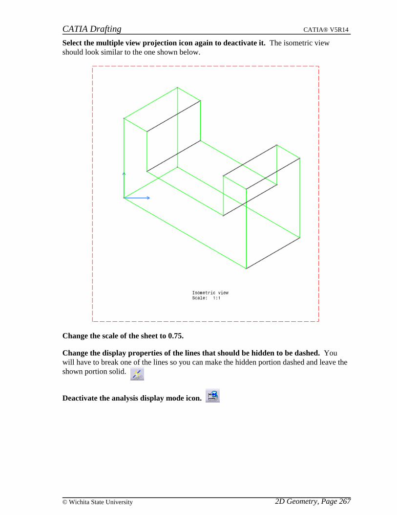
CATIA Drafting CATIA® V5R14
2D Geometry, Page 267© Wichita State University
Select the multiple view projection icon again to deactivate it. The isometric viewshould look similar to the one shown below.
Change the scale of the sheet to 0.75.
Change the display properties of the lines that should be hidden to be dashed. Youwill have to break one of the lines so you can make the hidden portion dashed and leave theshown portion solid.
Deactivate the analysis display mode icon.
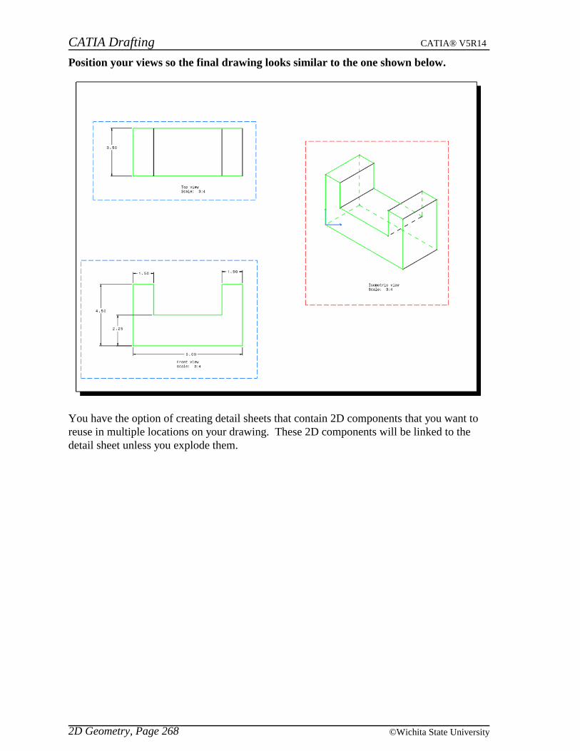
CATIA Drafting CATIA® V5R14
2D Geometry, Page 268 ©Wichita State University
Position your views so the final drawing looks similar to the one shown below.
You have the option of creating detail sheets that contain 2D components that you want toreuse in multiple locations on your drawing. These 2D components will be linked to thedetail sheet unless you explode them.

CATIA Drafting CATIA® V5R14
2D Geometry, Page 269© Wichita State University
2D Components
You need to create a detail sheet and then you can define a 2D component on that sheet.When you are ready to use the component on your drawing you will use the instantiate 2Dcomponent icon. You are going to quickly define a 2D component and then use it on yourdrawing. You have the option of putting these components in the catalog and then beingable to use them on a variety of drawings. That option will not be covered in this class.
Select the new detail sheet icon. It is located under the new sheet icon. A new sheetappears in your drawing but the label has the word (Detail) on it so you can distinguish adetail sheet from a regular sheet. A view is already available to define the 2D component.
Create a hexagon with a circle on the inside of the hexagon and dimensioned withdriving dimensions as shown below.
Go to Sheet.1 and activate the Top view.
Select the instantiate 2D component icon. You need to specify a component.
Go to Sheet.2 (Detail) and select the component. It automatically takes you back toSheet.1.
CATIA Drafting CATIA® V5R14
2D Geometry, Page 270 ©Wichita State University
Position the component and resize it by dragging the corner. It should appear similarto the one shown below.
Select the instantiate 2D component icon again.
Go to the detail sheet and select the component. You may not have noticed when youplaced the component last time but there are four additional options that you have toposition the component.
Change the component origin
Change the component angle
Flip across the vertical line
Flip across the horizontal line
You are not going to use any of these options in this case but you should know that theyexist.

CATIA Drafting CATIA® V5R14
2D Geometry, Page 271© Wichita State University
Position the component as shown. This time you are not going to resize it.
Go to the detail sheet and change the dimension of the inner circle to be 1.5 inches.
Return to Sheet.1. Notice that the circles automatically adjusted to be bigger because theyare linked to the detail. You have the option to explode the component into geometry that isnot linked by using the third mouse button. You can also add a leader to the componentusing the third mouse button.
Press the third mouse button while on the smaller component and choose the AddLeader option.
Select the origin point of the view. A leader appears from the center of the component tothe origin. There are times when you have many 2D Components in your drawing and youneed to modify the reference component.
Press the third mouse button while on the smaller component and choose EditReference Component.
Change the diameter of the inner circle to be 1.00 and return to Sheet.1. You can alsoreplace the reference component.
Go to Sheet.2 (Detail). You are going to create another component.
Select the new view icon and position it somewhere on the sheet and make it active.
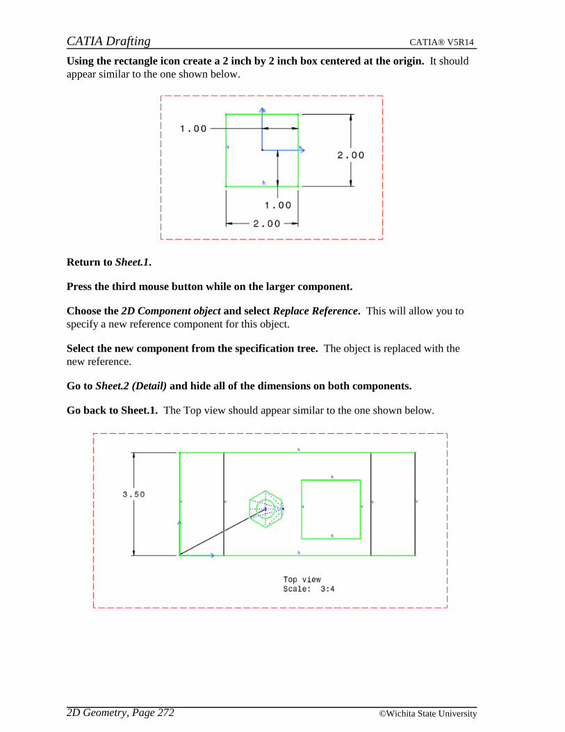
CATIA Drafting CATIA® V5R14
2D Geometry, Page 272 ©Wichita State University
Using the rectangle icon create a 2 inch by 2 inch box centered at the origin. It shouldappear similar to the one shown below.
Return to Sheet.1.
Press the third mouse button while on the larger component.
Choose the 2D Component object and select Replace Reference. This will allow you tospecify a new reference component for this object.
Select the new component from the specification tree. The object is replaced with thenew reference.
Go to Sheet.2 (Detail) and hide all of the dimensions on both components.
Go back to Sheet.1. The Top view should appear similar to the one shown below.

CATIA Drafting CATIA® V5R14
2D Geometry, Page 273© Wichita State University
Press the third mouse button while on the smaller component and select Properties.Make sure you are in the 2D Component Instance tab.
Position and orientation Allows you to key in a position in terms of X and Y, specify anAngle of rotation or modify the Scale of the instance
Change the scale to be 0.5 and select OK. The component changes to be half the size ofthe reference component. If you have the dimensions shown on the reference componentyou will not see them change on the instance even though it is at half scale. However, if youcreate your own dimension on the instance then it will reflect the actual size of thecomponent.
Save your drawing and close all documents.
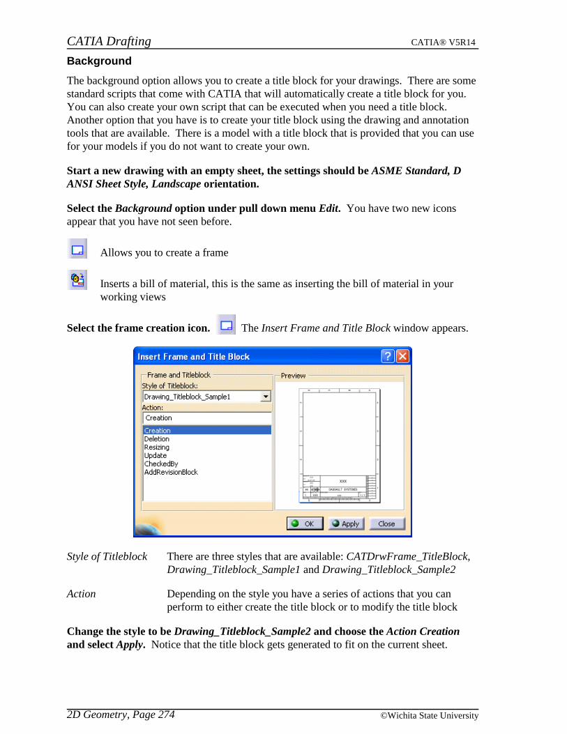
CATIA Drafting CATIA® V5R14
2D Geometry, Page 274 ©Wichita State University
Background
The background option allows you to create a title block for your drawings. There are somestandard scripts that come with CATIA that will automatically create a title block for you.You can also create your own script that can be executed when you need a title block.Another option that you have is to create your title block using the drawing and annotationtools that are available. There is a model with a title block that is provided that you can usefor your models if you do not want to create your own.
Start a new drawing with an empty sheet, the settings should be ASME Standard, DANSI Sheet Style, Landscape orientation.
Select the Background option under pull down menu Edit. You have two new iconsappear that you have not seen before.
Allows you to create a frame
Inserts a bill of material, this is the same as inserting the bill of material in yourworking views
Select the frame creation icon. The Insert Frame and Title Block window appears.
Style of Titleblock There are three styles that are available: CATDrwFrame_TitleBlock,Drawing_Titleblock_Sample1 and Drawing_Titleblock_Sample2
Action Depending on the style you have a series of actions that you canperform to either create the title block or to modify the title block
Change the style to be Drawing_Titleblock_Sample2 and choose the Action Creationand select Apply. Notice that the title block gets generated to fit on the current sheet.
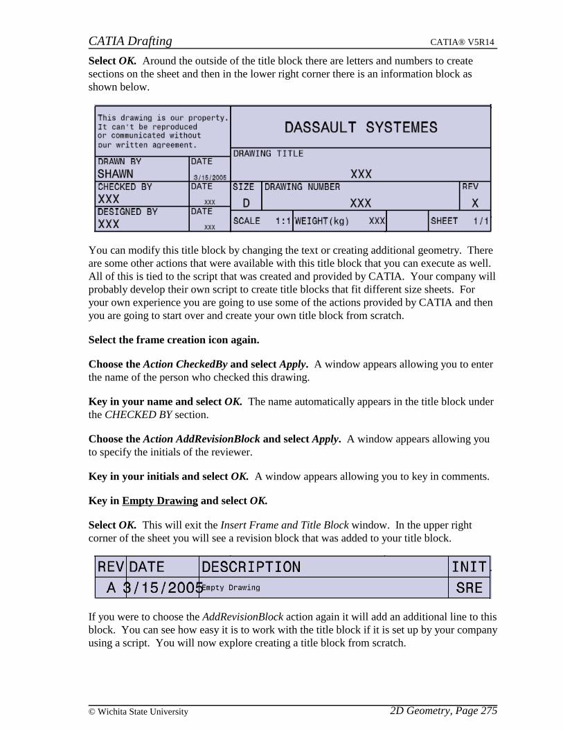
CATIA Drafting CATIA® V5R14
2D Geometry, Page 275© Wichita State University
Select OK. Around the outside of the title block there are letters and numbers to createsections on the sheet and then in the lower right corner there is an information block asshown below.
You can modify this title block by changing the text or creating additional geometry. Thereare some other actions that were available with this title block that you can execute as well.All of this is tied to the script that was created and provided by CATIA. Your company willprobably develop their own script to create title blocks that fit different size sheets. Foryour own experience you are going to use some of the actions provided by CATIA and thenyou are going to start over and create your own title block from scratch.
Select the frame creation icon again.
Choose the Action CheckedBy and select Apply. A window appears allowing you to enterthe name of the person who checked this drawing.
Key in your name and select OK. The name automatically appears in the title block underthe CHECKED BY section.
Choose the Action AddRevisionBlock and select Apply. A window appears allowing youto specify the initials of the reviewer.
Key in your initials and select OK. A window appears allowing you to key in comments.
Key in Empty Drawing and select OK.
Select OK. This will exit the Insert Frame and Title Block window. In the upper rightcorner of the sheet you will see a revision block that was added to your title block.
If you were to choose the AddRevisionBlock action again it will add an additional line to thisblock. You can see how easy it is to work with the title block if it is set up by your companyusing a script. You will now explore creating a title block from scratch.

CATIA Drafting CATIA® V5R14
2D Geometry, Page 276 ©Wichita State University
Close this drawing without saving. You are going to create your own title block.
Start a new drawing with the same parameters.
Select the Background option under pull down menu Edit. Since you do not want tohave to create the boundary area yourself you are going to use one of the styles to createthat. Then you are going to modify the information block.
Select the frame creation icon.
Choose the style Drawing_Titleblock_Sample2 and the Action Creation and select OK.The title block is generated. You are now going to modify it.
Remove all the geometry associated with the information block. The lower right cornershould look like the one shown below.
Using annotations and drawing tools create the information block so it appears similarto the one shown below. Make sure you turn the show constraints icon off. .

CATIA Drafting CATIA® V5R14
2D Geometry, Page 277© Wichita State University
You can enter text in the different locations so that the person creating the drawing canmodify the formula in order to enter their information. This keeps the person from havingto position the text properly.
Create text next to Drawn By of XXX. Make sure you position it correctly. You are goingto create a parameter that you will link to this text.
Select the formula icon in the bottom toolbar.
Change the parameter type to String and select the New Parameter of type button. Anew parameter is created and you can change the name of it and set a value.
Change the name to be Drawn by and the value to be Name and select OK. Aparameters branch appears in the specification tree.
Double select the XXX text.
Press the third mouse button while on the XXX text and select Attribute link. You aregoing to link this text to the created parameter.
Select the Parameters branch and the Drawn by parameter in the specification tree andselect the Drawn by attribute in the window and select OK.
Select OK in the Text Editor window. That attribute is now linked to the text at thatlocation. You can change the text by simply double selecting the parameter from the list.
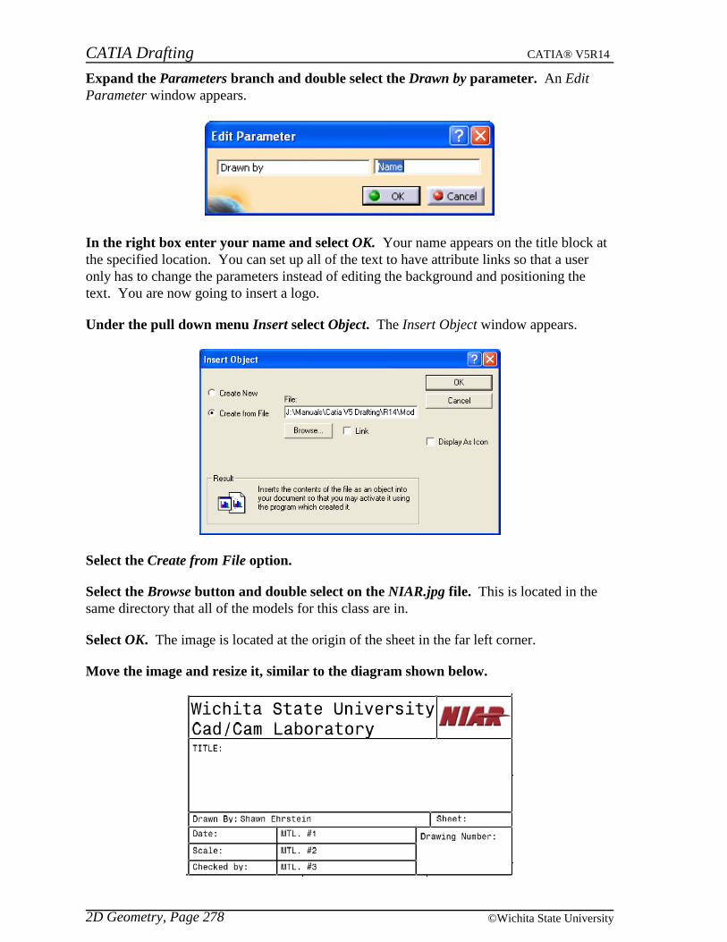
CATIA Drafting CATIA® V5R14
2D Geometry, Page 278 ©Wichita State University
Expand the Parameters branch and double select the Drawn by parameter. An EditParameter window appears.
In the right box enter your name and select OK. Your name appears on the title block atthe specified location. You can set up all of the text to have attribute links so that a useronly has to change the parameters instead of editing the background and positioning thetext. You are now going to insert a logo.
Under the pull down menu Insert select Object. The Insert Object window appears.
Select the Create from File option.
Select the Browse button and double select on the NIAR.jpg file. This is located in thesame directory that all of the models for this class are in.
Select OK. The image is located at the origin of the sheet in the far left corner.
Move the image and resize it, similar to the diagram shown below.

CATIA Drafting CATIA® V5R14
2D Geometry, Page 279© Wichita State University
You have the option of creating your own title block, modifying this one or use the one thatis provided with the class for your problems. The information block should contain thefollowing information: drawn by, date, scale, sheet, drawing number and title. Any otherinformation that you want the title block to contain is up to you. There is no need to add arevision area until revisions are made unless you want to. If you want you can createadditional text and link it to parameters for the other areas of the information block.
Change the title block at your discretion.
Select Working Views from the pull down menu Edit. This will return you to the workingarea out of the background.
Save this title block in your area. This will be the title block that you will use for yourdrawings or you can use the one provided for you.
Close all documents.
Start a new drawing with an empty sheet, the settings should be ASME Standard, DANSI Sheet Style, Landscape orientation.
Select the Page Setup option under the pull down menu File. The Page Setup windowappears.
Select the Insert Background View... button.
Select the Browse button and select the Title block D size drawing. You will beinserting the background that has already been created for you. When you do your problemsyou have the option of using this one or the one you created earlier.
Select Insert.
Select OK. The background appears without its parameters.
CATIA Drafting CATIA® V5R14
2D Geometry, Page 280 ©Wichita State University
If you want the parameters to be available you need to open the title block document andthen save it with a different name each time you are ready to begin a new drawing.
Close this drawing and open the Title block D size drawing.
Save this drawing as Problem #01. This will prepare you for creating the views necessaryfor the first problem.

CATIA Drafting CATIA® V5R14
Review, Page 281© Wichita State University
Review
You can choose how much review you would like to do. If you want to start at the verybeginning you can start with the GDT part and create the views and then dimension,annotate and markup the views as necessary. If you want to start with the views alreadycreated then you can use the GDT drawing and then dimension, annotate and markup theviews as necessary. If you want to begin with most of the dimensions done then you can usethe GDTfinished drawing. If you want to begin where you left off with the part earlier inthe class then you can start with the GDTfinished2 drawing. The exercise will show youthe steps if you start with the GDTfinished2 drawing. If you begin earlier then you need tocreate the necessary views or dimensions as shown in each diagram. The finished problemwill appear as shown below.

CATIA Drafting CATIA® V5R14
Review, Page 282 ©Wichita State University
Open the GDTfinished2 drawing. You can open your GDTfinished drawing if you wish,however this one is provided for you in case you did not save.
In the Section view you need to add the following notation.
You will need to add text with a leader and then create a geometrical toleranceattached to the text. This will complete the Section view.
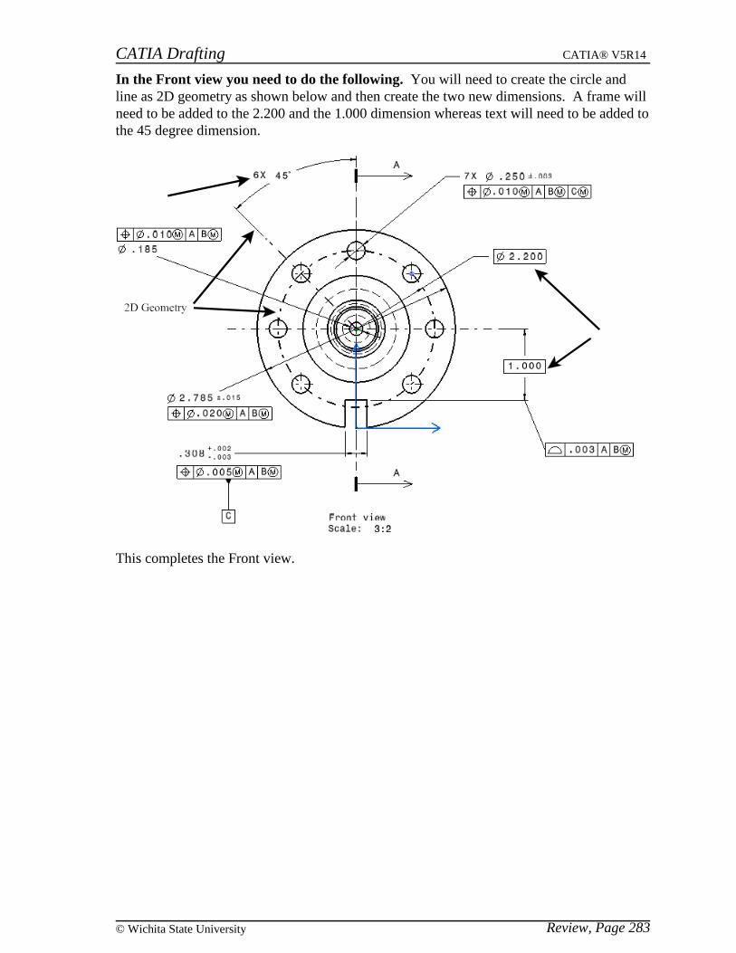
CATIA Drafting CATIA® V5R14
Review, Page 283© Wichita State University
In the Front view you need to do the following. You will need to create the circle andline as 2D geometry as shown below and then create the two new dimensions. A frame willneed to be added to the 2.200 and the 1.000 dimension whereas text will need to be added tothe 45 degree dimension.
This completes the Front view.
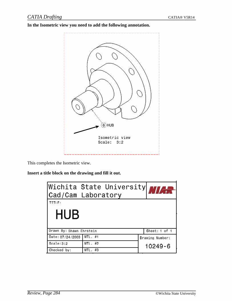
CATIA Drafting CATIA® V5R14
Review, Page 284 ©Wichita State University
In the Isometric view you need to add the following annotation.
This completes the Isometric view.
Insert a title block on the drawing and fill it out.
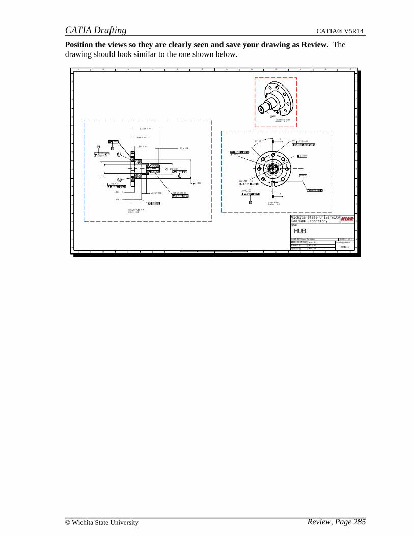
CATIA Drafting CATIA® V5R14
Review, Page 285© Wichita State University
Position the views so they are clearly seen and save your drawing as Review. Thedrawing should look similar to the one shown below.

CATIA Drafting CATIA® V5R14
Review, Page 286 ©Wichita State University
Geometry in all viewpoints
Using this review problem, you will look at two final icons. The first is an analysis tool thatlets you see geometry in all viewpoints.
Select the show geometry in all viewpoints icon. This icon can be found by turningthe Analyze option on under the pull down menu View, Toolbars. A 3D Viewer windowappears, showing you the current view.
Make sure the Animate option is on.
Move the cursor on top of the large circle in the Front view. It highlights in blue and youcan see the element highlight in the other views as well. This is a great tool to use when youare trying to see where an element exists in all the views.
Move the cursor around to other views and other elements.
Close the window when done. You can do this by selecting the X in the upper rightcorner.
Filter generated elements
The second icon is the filter generated elements icon. This will dim all the elements thathave been generated from 3D. This is a quick method to check what has been manuallycreated.
Select the filter generated elements icon. It is located in the Tools toolbar. Thisdims all the geometry that has been generated from 3D. Notice that the circle and line thatyou created in the Front view are not dimmed as well as the title block and the dimensions.
Select the filter generated elements icon again. This turns the filter off.
Exporting
You can easily export a drawing into different formats by changing the type when you saveyour document.
Go to Save As under pull down menu File. In the Save as type area you can select thearrow to specify what file type you want the drawing saved in.
Change the type to pdf and the name to draw.pdf and select Save. This creates a pdf filethat can be put on a web site.
Save the drawing again using the type tif and change the name to draw.tif. This createsa tif file that can be used with a word processor, like Microsoft Word.
Close all documents. You do not need to save this drawing since you saved it earlier.

CATIA Drafting CATIA® V5R14
Problems, Page 287© Wichita State University
Problems
Problem #01
Create the following views and dimensions.

CATIA Drafting CATIA® V5R14
Problems, Page 288 ©Wichita State University
Problem #02
Create the following views and dimensions.

CATIA Drafting CATIA® V5R14
Problems, Page 289© Wichita State University
Problem #03
Create the following views and dimensions.

CATIA Drafting CATIA® V5R14
Problems, Page 290 ©Wichita State University
Problem #04
Create the following views and dimensions.
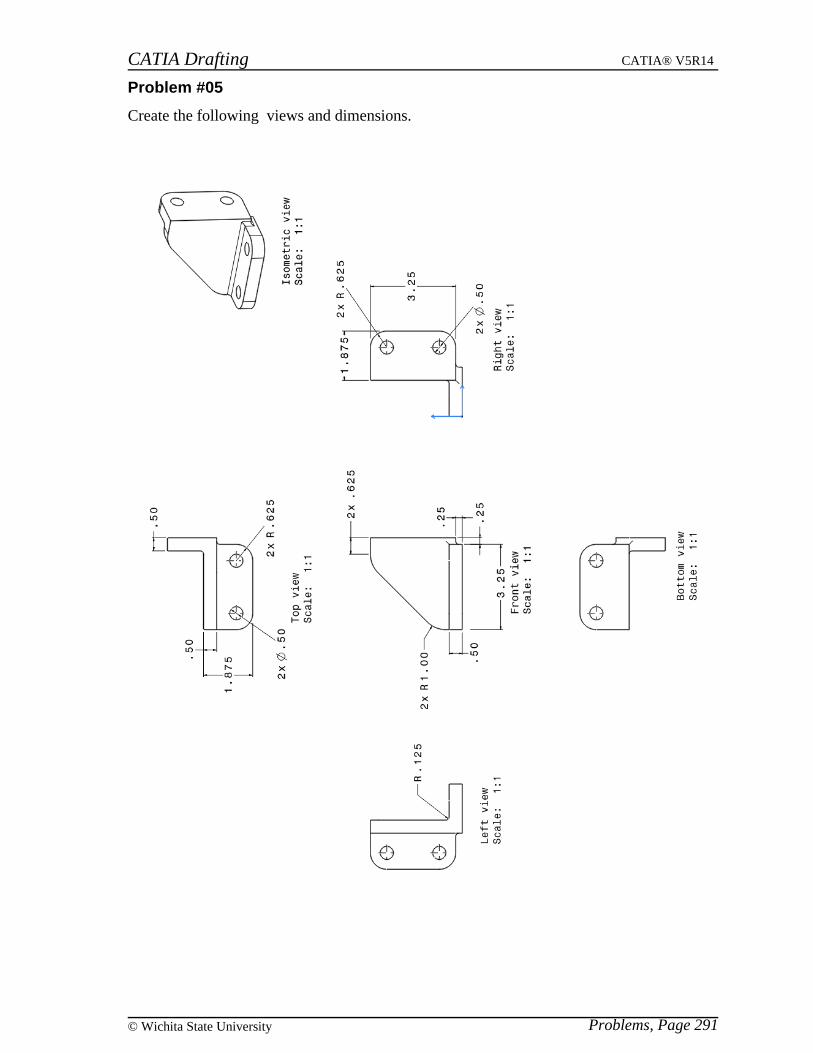
CATIA Drafting CATIA® V5R14
Problems, Page 291© Wichita State University
Problem #05
Create the following views and dimensions.
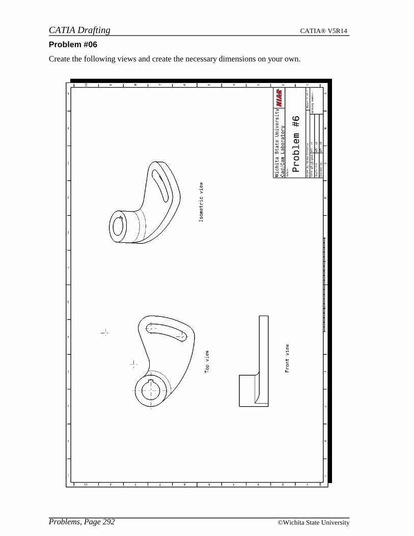
CATIA Drafting CATIA® V5R14
Problems, Page 292 ©Wichita State University
Problem #06
Create the following views and create the necessary dimensions on your own.

CATIA Drafting CATIA® V5R14
Problems, Page 293© Wichita State University
Problem #07
Create the following views and create the necessary dimensions on your own.
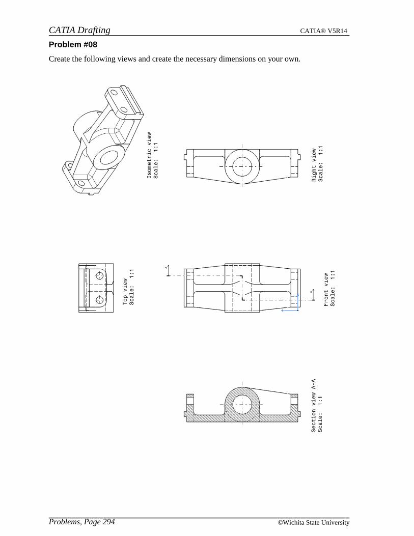
CATIA Drafting CATIA® V5R14
Problems, Page 294 ©Wichita State University
Problem #08
Create the following views and create the necessary dimensions on your own.
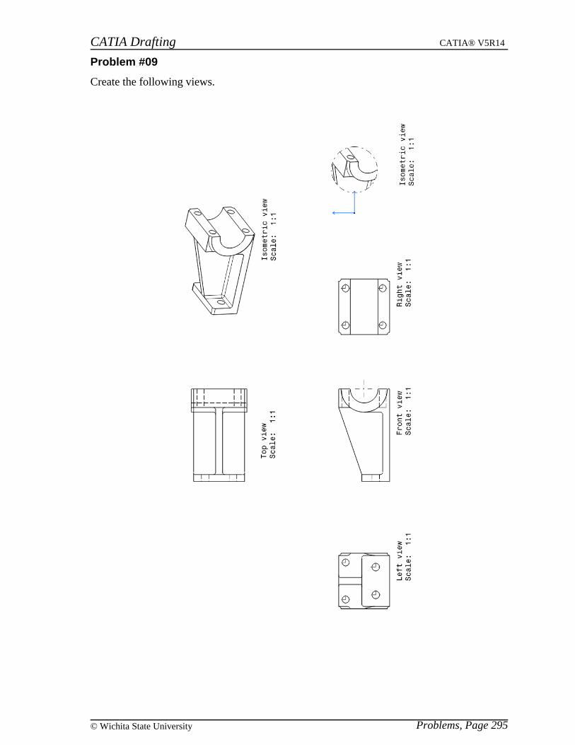
CATIA Drafting CATIA® V5R14
Problems, Page 295© Wichita State University
Problem #09
Create the following views.
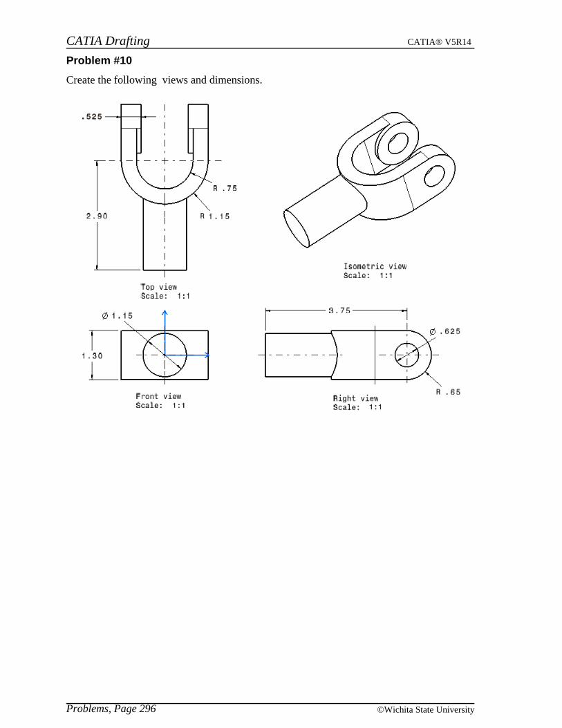
CATIA Drafting CATIA® V5R14
Problems, Page 296 ©Wichita State University
Problem #10
Create the following views and dimensions.
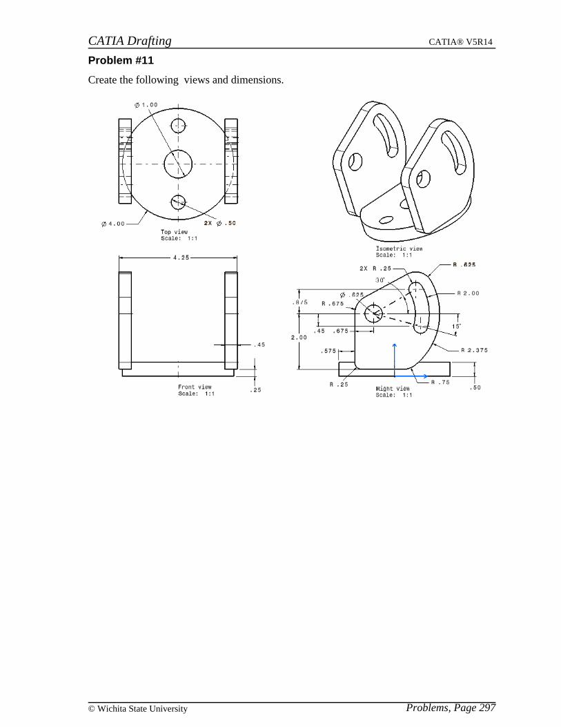
CATIA Drafting CATIA® V5R14
Problems, Page 297© Wichita State University
Problem #11
Create the following views and dimensions.

CATIA Drafting CATIA® V5R14
Problems, Page 298 ©Wichita State University
Problem #12
Create the necessary views and dimensions for the part below.
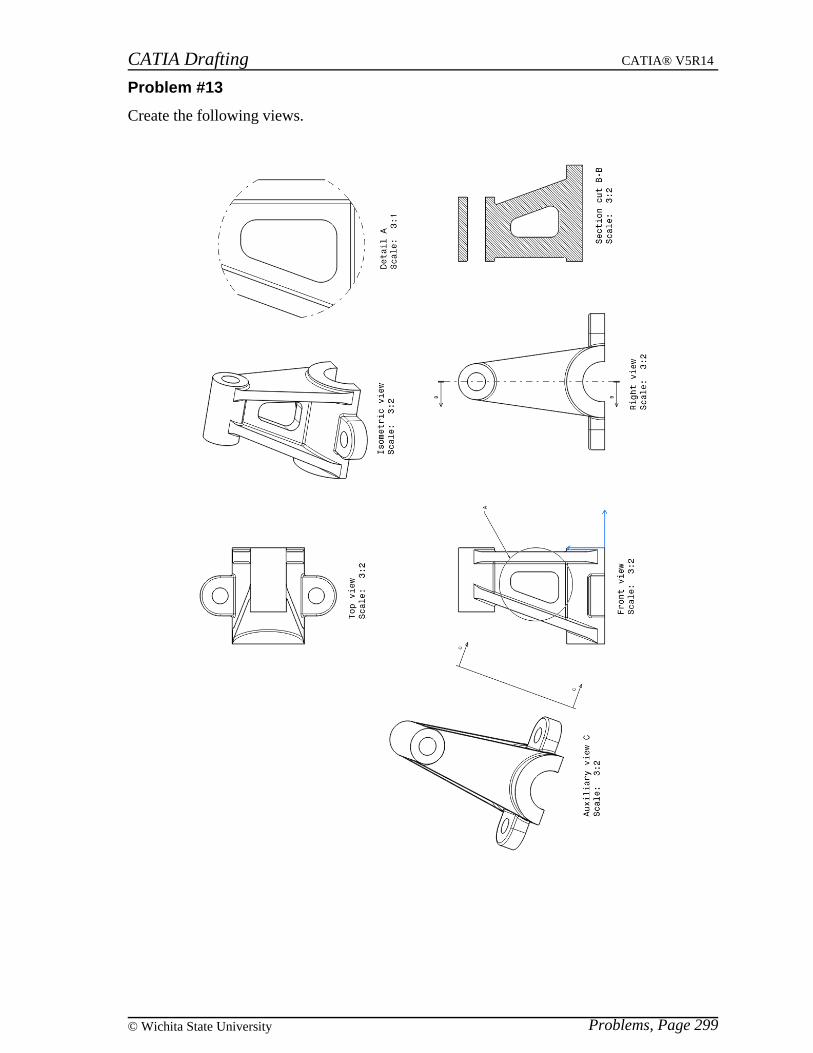
CATIA Drafting CATIA® V5R14
Problems, Page 299© Wichita State University
Problem #13
Create the following views.
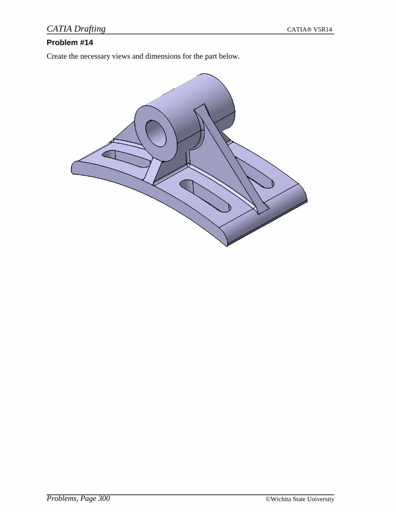
CATIA Drafting CATIA® V5R14
Problems, Page 300 ©Wichita State University
Problem #14
Create the necessary views and dimensions for the part below.

CATIA Drafting CATIA® V5R14
Problems, Page 301© Wichita State University
Problem #15
Create the following views for the product below, including a view of the scene with the billof material. Also create views for the individual parts.
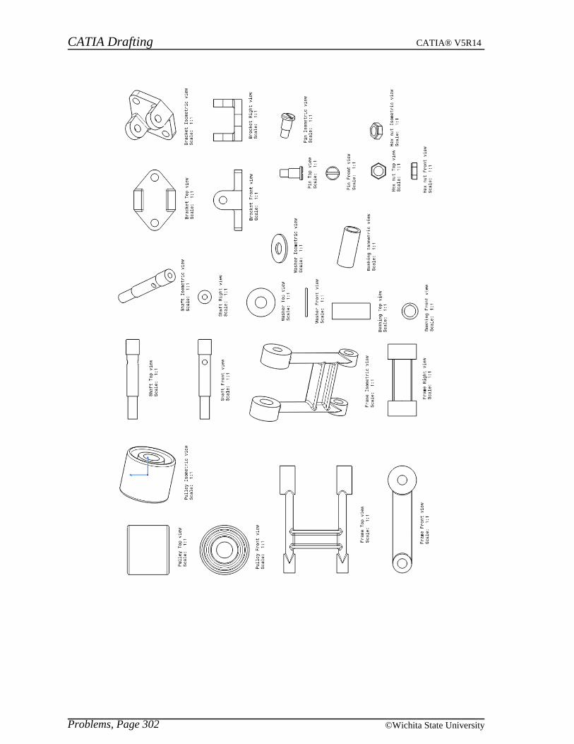
CATIA Drafting CATIA® V5R14
Problems, Page 302 ©Wichita State University
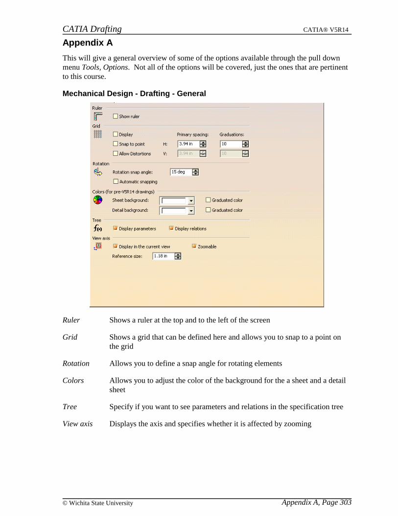
CATIA Drafting CATIA® V5R14
Appendix A, Page 303© Wichita State University
Appendix A
This will give a general overview of some of the options available through the pull downmenu Tools, Options. Not all of the options will be covered, just the ones that are pertinentto this course.
Mechanical Design - Drafting - General
Ruler Shows a ruler at the top and to the left of the screen
Grid Shows a grid that can be defined here and allows you to snap to a point onthe grid
Rotation Allows you to define a snap angle for rotating elements
Colors Allows you to adjust the color of the background for the a sheet and a detailsheet
Tree Specify if you want to see parameters and relations in the specification tree
View axis Displays the axis and specifies whether it is affected by zooming

CATIA Drafting CATIA® V5R14
Appendix A, Page 304 ©Wichita State University
Mechanical Design - Drafting - Layout
View Creation Specifies what gets generated when a new view is created.The View name, Scaling factor and View frame are on bydefault. You can also specify that you want the broken andbreakout specifications to propagate to new views. You canspecify if you want auxiliary views and section views to orientthemselves according to the profile. You can also specifywhether or not you would like the view axis system based onthe 3D axis system.
New Sheet Copies the background view to all new sheets. The sourcesheet can be set to be the first sheet or from another drawing.
Background View Specifies the location of for the frame and title block scripts
Section / Projection Callout Specifies if the callout is affected by the scale of the view
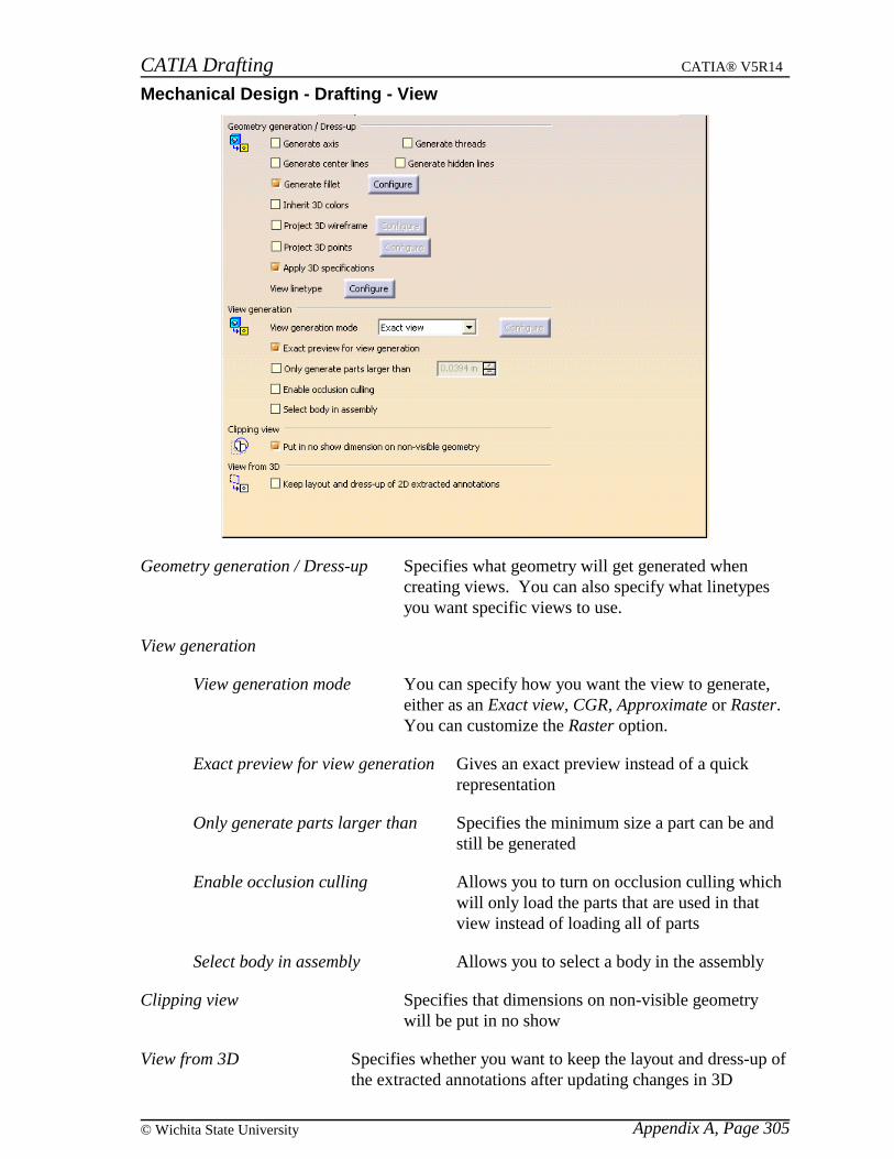
CATIA Drafting CATIA® V5R14
Appendix A, Page 305© Wichita State University
Mechanical Design - Drafting - View
Geometry generation / Dress-up Specifies what geometry will get generated whencreating views. You can also specify what linetypesyou want specific views to use.
View generation
View generation mode You can specify how you want the view to generate,either as an Exact view, CGR, Approximate or Raster.You can customize the Raster option.
Exact preview for view generation Gives an exact preview instead of a quickrepresentation
Only generate parts larger than Specifies the minimum size a part can be andstill be generated
Enable occlusion culling Allows you to turn on occlusion culling whichwill only load the parts that are used in thatview instead of loading all of parts
Select body in assembly Allows you to select a body in the assembly
Clipping view Specifies that dimensions on non-visible geometrywill be put in no show
View from 3D Specifies whether you want to keep the layout and dress-up ofthe extracted annotations after updating changes in 3D

CATIA Drafting CATIA® V5R14
Appendix A, Page 306 ©Wichita State University
Mechanical Design - Drafting - Generation
Dimension generation Specifies what you want to happen when you are generatingdimensions
Balloon generation Generates a balloon for each instance of an element instead ofjust creating one balloon for all instances
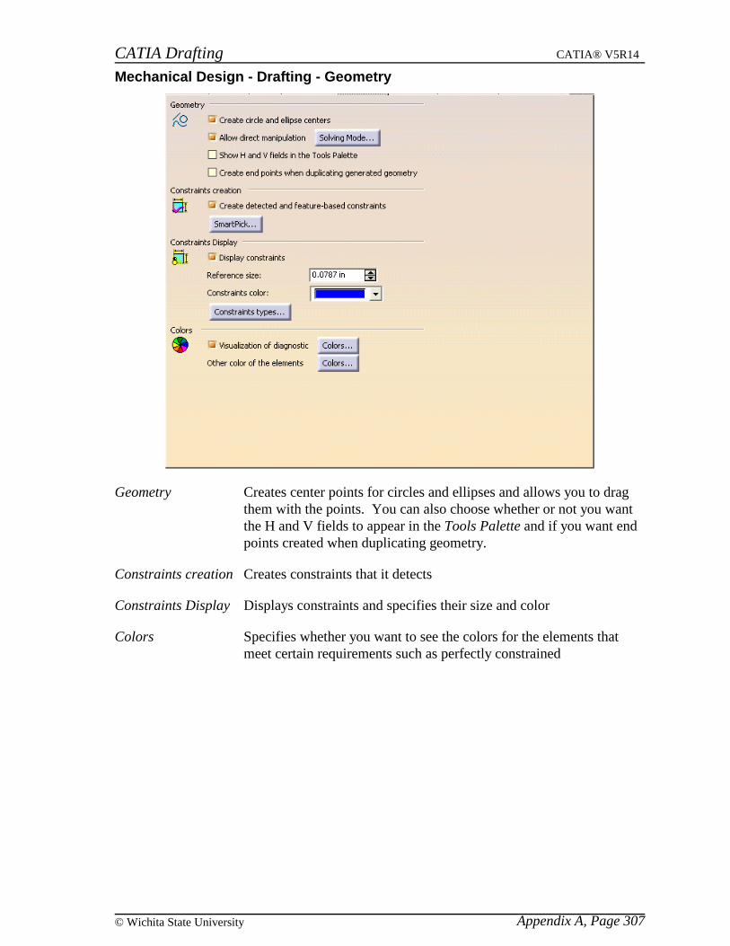
CATIA Drafting CATIA® V5R14
Appendix A, Page 307© Wichita State University
Mechanical Design - Drafting - Geometry
Geometry Creates center points for circles and ellipses and allows you to dragthem with the points. You can also choose whether or not you wantthe H and V fields to appear in the Tools Palette and if you want endpoints created when duplicating geometry.
Constraints creation Creates constraints that it detects
Constraints Display Displays constraints and specifies their size and color
Colors Specifies whether you want to see the colors for the elements thatmeet certain requirements such as perfectly constrained
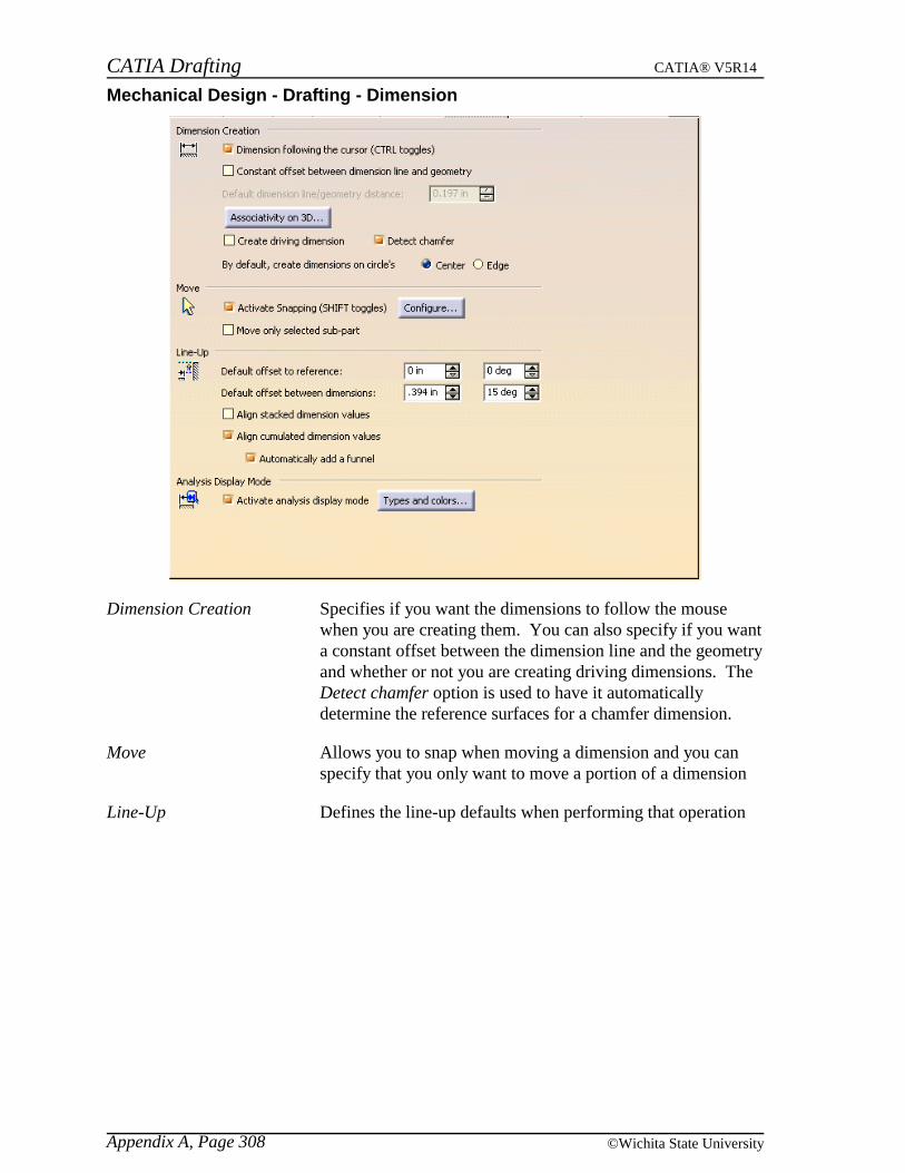
CATIA Drafting CATIA® V5R14
Appendix A, Page 308 ©Wichita State University
Mechanical Design - Drafting - Dimension
Dimension Creation Specifies if you want the dimensions to follow the mousewhen you are creating them. You can also specify if you wanta constant offset between the dimension line and the geometryand whether or not you are creating driving dimensions. TheDetect chamfer option is used to have it automaticallydetermine the reference surfaces for a chamfer dimension.
Move Allows you to snap when moving a dimension and you canspecify that you only want to move a portion of a dimension
Line-Up Defines the line-up defaults when performing that operation

CATIA Drafting CATIA® V5R14
Appendix A, Page 309© Wichita State University
Analysis Display Mode Toggles whether or not you want to see the colors associatedwith certain types of dimensions
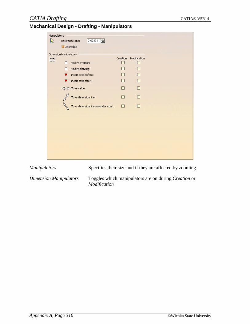
CATIA Drafting CATIA® V5R14
Appendix A, Page 310 ©Wichita State University
Mechanical Design - Drafting - Manipulators
Manipulators Specifies their size and if they are affected by zooming
Dimension Manipulators Toggles which manipulators are on during Creation orModification
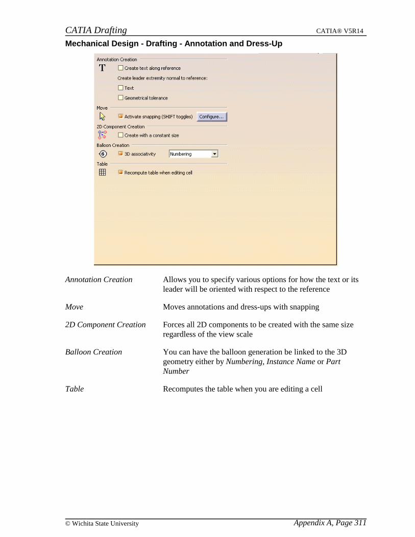
CATIA Drafting CATIA® V5R14
Appendix A, Page 311© Wichita State University
Mechanical Design - Drafting - Annotation and Dress-Up
Annotation Creation Allows you to specify various options for how the text or itsleader will be oriented with respect to the reference
Move Moves annotations and dress-ups with snapping
2D Component Creation Forces all 2D components to be created with the same sizeregardless of the view scale
Balloon Creation You can have the balloon generation be linked to the 3Dgeometry either by Numbering, Instance Name or PartNumber
Table Recomputes the table when you are editing a cell

CATIA Drafting CATIA® V5R14
Appendix A, Page 312 ©Wichita State University
Mechanical Design - Drafting - Administration
Drawing management Allows for the prevention of certain tasks, such as switchingor updating the standard
Style Sets how the styles will be used
Generative view style Prevents users from being able to create view styles
Dress-up Prevents generated dimensions from driving 3D constraints

.
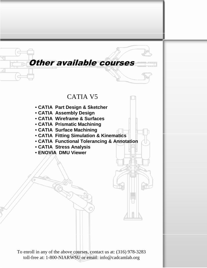
Other available courses
CATIA V5
• CATIA Part Design & Sketcher• CATIA Assembly Design• CATIA Wireframe & Surfaces• CATIA Prismatic Machining• CATIA Surface Machining• CATIA Fitting Simulation & Kinematics• CATIA Functional Tolerancing & Annotation• CATIA Stress Analysis• ENOVIA DMU Viewer
To enroll in any of the above courses, contact us at: (316) 978-3283toll-free at: 1-800-NIARWSU or email: [email protected]


