Copyright 2005 SSD Drives Limited (formerly Eurotherm Drives Limited) All rights strictly reserved. No part of this document may be stored in a retrieval system, or transmitted in any form or by any means to persons not employed by an SSD Drives company without written permission from SSD Drives Ltd. Although every effort has been taken to ensure the accuracy of this document it may be necessary, without notice, to make amendments or correct omissions. SSD Drives cannot accept responsibility for damage, injury, or expenses resulting therefrom. 8903/PB Profibus Communications Interface Technical Manual HA469267U001 Issue 1 Compatible with 890 Firmware Version 1.4 onwards
All rights strictly reserved. No part of this document may be stored in a retrieval system, or transmitted in any form or byany means to persons not employed by an SSD Drives company without written permission from SSD Drives Ltd.
Although every effort has been taken to ensure the accuracy of this document it may be necessary, without notice, tomake amendments or correct omissions. SSD Drives cannot accept responsibility for damage, injury, or expensesresulting therefrom.
8903/PB ProfibusCommunications Interface
Technical ManualHA469267U001 Issue 1
Compatible with 890 Firmware Version 1.4 onwards
Cont.3
WARNING! During commissioning, remove the fuses (or trip the circuit breaker) on your 3-
phase supply.Make sure the power is OFF, and that it cannot be switched on accidentally whilst
you are working.
Please read this information BEFORE installing the equipment.
Intended UsersThis manual is to be made available to all persons who are required to install, configure orservice equipment described herein, or any other associated operation.
The information given is intended to highlight safety issues, and to enable the user to obtainmaximum benefit from the equipment.
Application AreaThe equipment described is intended for industrial motor speed control.
PersonnelInstallation, operation and maintenance of the equipment should be carried out by qualifiedpersonnel. A qualified person is someone who is technically competent and familiar with allsafety information and established safety practices; with the installation process, operation andmaintenance of this equipment; and with all the hazards involved.
REFER TO YOUR MAIN PRODUCT MANUAL FOR SPECIFIC SAFETYINFORMATION ABOUT THE DEVICE YOU ARE CONTROLLING
AcknowledgementsDSE (Drives System Explorer) is a registered trademark of SSD Drives, Inc.
Simatic and STEP 7 are registered trademarks of Siemens.
Profibus is a trademark of PROFIBUS International.
!Safety Information
WARRANTYSSD Drives warrants the goods against defects in design, materials and workmanship
for the period of 12 months from the date of delivery on the termsdetailed in SSD Drives Standard Conditions of Sale IA058393C.
SSD Drives reserves the right to change the content and product specificationwithout notice.
• PKW (Demand Data) Processing ............................................................. 18• Command............................................................................................. 18• Parameter Reference.............................................................................. 19• Parameter Value or Error Code .............................................................. 19
Appendix A : Troubleshooting....................................................................... 20
• 890 Profibus TechCard Status LED.......................................................... 20
Appendix B : DSE/Profibus Conversion Rules................................................ 21
• LOGIC Type Connector ......................................................................... 21• INTEGER Type Connector....................................................................... 22• VALUE Type Connector .......................................................................... 23
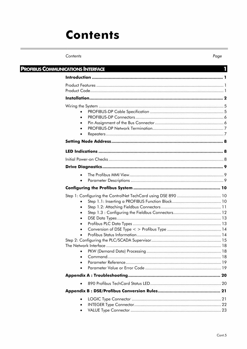
Contents
Contents Page
Cont.6
1
8903/PB Profibus Communications Interface
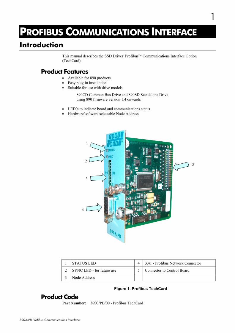
PROFIBUS COMMUNICATIONS INTERFACEIntroduction
This manual describes the SSD Drives' Profibus Communications Interface Option(TechCard).
Product Features• Available for 890 products• Easy plug-in installation• Suitable for use with drive models:
890CD Common Bus Drive and 890SD Standalone Driveusing 890 firmware version 1.4 onwards
• LED’s to indicate board and communications status• Hardware/software selectable Node Address
1 STATUS LED 4 X41 - Profibus Network Connector
2 SYNC LED - for future use 5 Connector to Control Board
drive wiring is electrically isolated andcannot be made “live” unintentionally
by other personnel.Wait 5 minutes after disconnecting
power before working on any part ofthe system or removing the covers
from the drives.
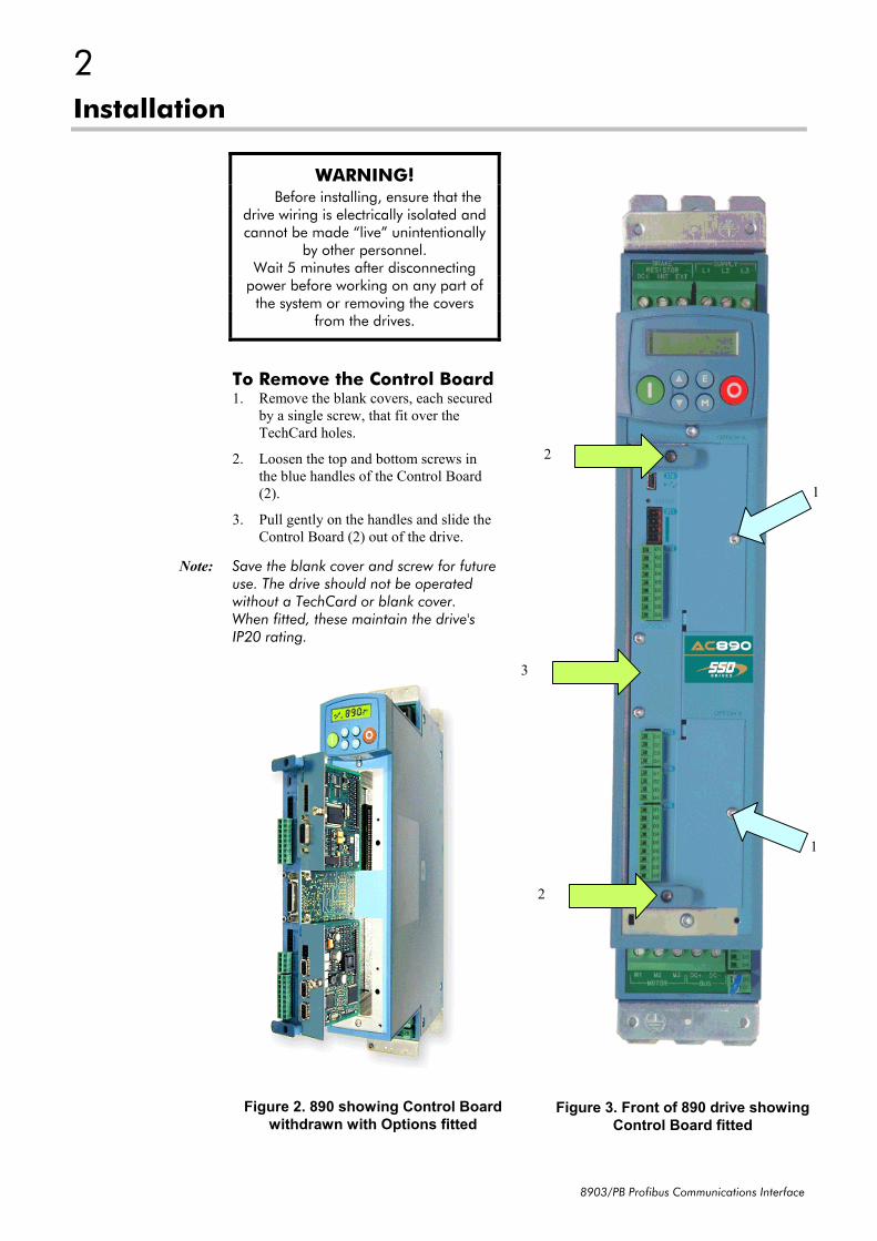
To Remove the Control Board1. Remove the blank covers, each secured
by a single screw, that fit over theTechCard holes.
2. Loosen the top and bottom screws inthe blue handles of the Control Board(2).
3. Pull gently on the handles and slide theControl Board (2) out of the drive.
Note: Save the blank cover and screw for futureuse. The drive should not be operatedwithout a TechCard or blank cover.When fitted, these maintain the drive'sIP20 rating.
Figure 3. Front of 890 drive showingControl Board fitted
Figure 2. 890 showing Control Boardwithdrawn with Options fitted
3
8903/PB Profibus Communications Interface
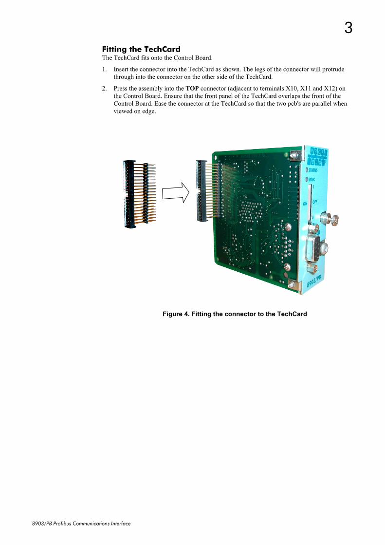
Fitting the TechCardThe TechCard fits onto the Control Board.
1. Insert the connector into the TechCard as shown. The legs of the connector will protrudethrough into the connector on the other side of the TechCard.
2. Press the assembly into the TOP connector (adjacent to terminals X10, X11 and X12) onthe Control Board. Ensure that the front panel of the TechCard overlaps the front of theControl Board. Ease the connector at the TechCard so that the two pcb's are parallel whenviewed on edge.
Figure 4. Fitting the connector to the TechCard
4
8903/PB Profibus Communications Interface
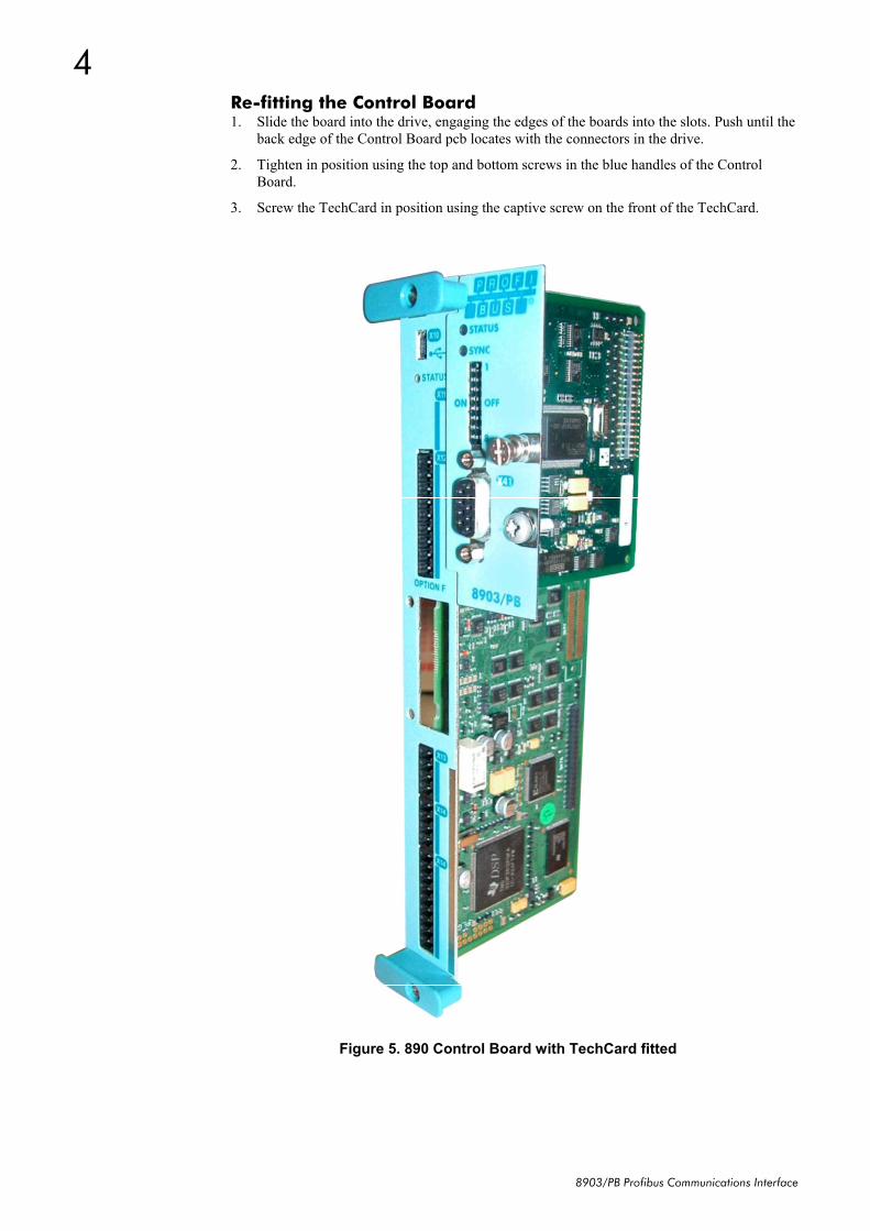
Re-fitting the Control Board1. Slide the board into the drive, engaging the edges of the boards into the slots. Push until the
back edge of the Control Board pcb locates with the connectors in the drive.
2. Tighten in position using the top and bottom screws in the blue handles of the ControlBoard.
3. Screw the TechCard in position using the captive screw on the front of the TechCard.
Figure 5. 890 Control Board with TechCard fitted
5
8903/PB Profibus Communications Interface
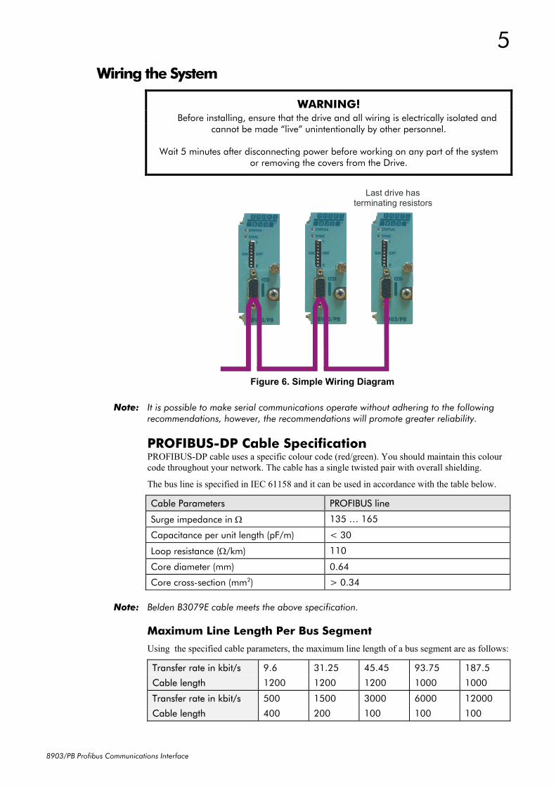
Wiring the System
WARNING! Before installing, ensure that the drive and all wiring is electrically isolated and
cannot be made “live” unintentionally by other personnel.
Wait 5 minutes after disconnecting power before working on any part of the systemor removing the covers from the Drive.
Note: It is possible to make serial communications operate without adhering to the followingrecommendations, however, the recommendations will promote greater reliability.
PROFIBUS-DP Cable SpecificationPROFIBUS-DP cable uses a specific colour code (red/green). You should maintain this colourcode throughout your network. The cable has a single twisted pair with overall shielding.
The bus line is specified in IEC 61158 and it can be used in accordance with the table below.
Cable Parameters PROFIBUS line
Surge impedance in Ω 135 … 165
Capacitance per unit length (pF/m) < 30
Loop resistance (Ω/km) 110
Core diameter (mm) 0.64
Core cross-section (mm2) > 0.34
Note: Belden B3079E cable meets the above specification.
Maximum Line Length Per Bus Segment
Using the specified cable parameters, the maximum line length of a bus segment are as follows:
Transfer rate in kbit/s 9.6 31.25 45.45 93.75 187.5
Cable length 1200 1200 1200 1000 1000
Transfer rate in kbit/s 500 1500 3000 6000 12000
Cable length 400 200 100 100 100
Figure 6. Simple Wiring Diagram
Last drive hasterminating resistors
6
8903/PB Profibus Communications Interface
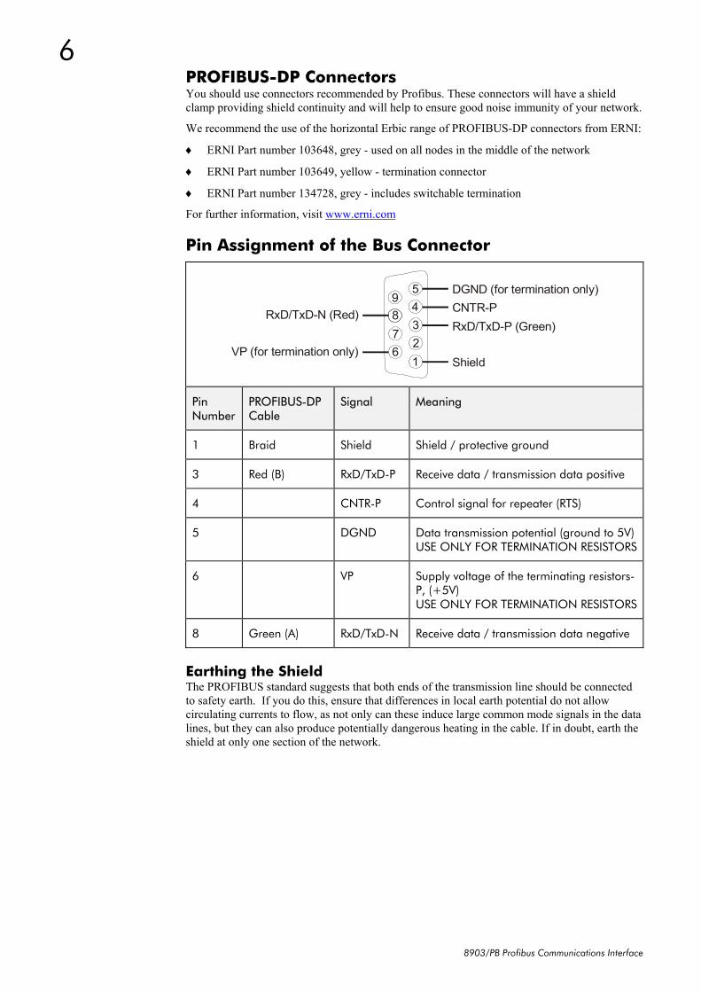
PROFIBUS-DP ConnectorsYou should use connectors recommended by Profibus. These connectors will have a shieldclamp providing shield continuity and will help to ensure good noise immunity of your network.
We recommend the use of the horizontal Erbic range of PROFIBUS-DP connectors from ERNI:
♦ ERNI Part number 103648, grey - used on all nodes in the middle of the network
♦ ERNI Part number 103649, yellow - termination connector
♦ ERNI Part number 134728, grey - includes switchable termination
3 Red (B) RxD/TxD-P Receive data / transmission data positive
4 CNTR-P Control signal for repeater (RTS)
5 DGND Data transmission potential (ground to 5V)USE ONLY FOR TERMINATION RESISTORS
6 VP Supply voltage of the terminating resistors-P, (+5V)USE ONLY FOR TERMINATION RESISTORS
8 Green (A) RxD/TxD-N Receive data / transmission data negative
Earthing the ShieldThe PROFIBUS standard suggests that both ends of the transmission line should be connectedto safety earth. If you do this, ensure that differences in local earth potential do not allowcirculating currents to flow, as not only can these induce large common mode signals in the datalines, but they can also produce potentially dangerous heating in the cable. If in doubt, earth theshield at only one section of the network.
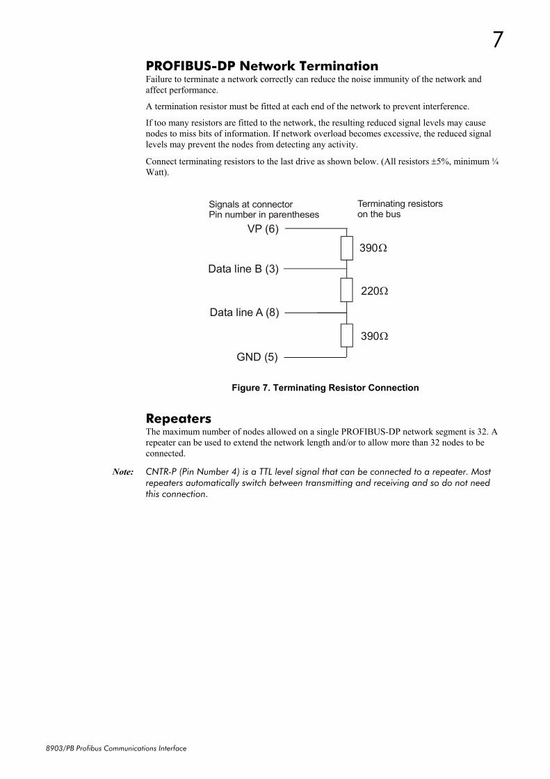
PROFIBUS-DP Network TerminationFailure to terminate a network correctly can reduce the noise immunity of the network andaffect performance.
A termination resistor must be fitted at each end of the network to prevent interference.
If too many resistors are fitted to the network, the resulting reduced signal levels may causenodes to miss bits of information. If network overload becomes excessive, the reduced signallevels may prevent the nodes from detecting any activity.
Connect terminating resistors to the last drive as shown below. (All resistors ±5%, minimum ¼Watt).
Data line B (3)
Data line A (8)
GND (5)
VP (6) 390 Ω
220 Ω
390 Ω
Terminating resistorson the bus
Signals at connectorPin number in parentheses
RepeatersThe maximum number of nodes allowed on a single PROFIBUS-DP network segment is 32. Arepeater can be used to extend the network length and/or to allow more than 32 nodes to beconnected.
Note: CNTR-P (Pin Number 4) is a TTL level signal that can be connected to a repeater. Mostrepeaters automatically switch between transmitting and receiving and so do not needthis connection.
Figure 7. Terminating Resistor Connection
8
8903/PB Profibus Communications Interface
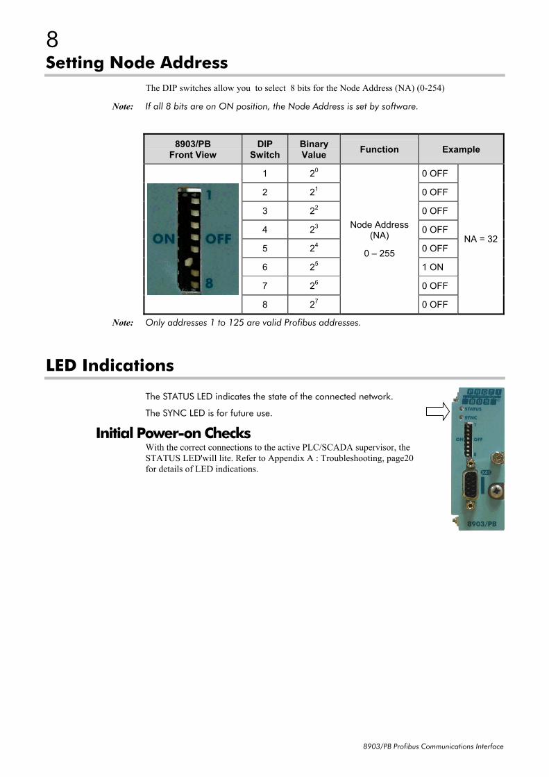
Setting Node AddressThe DIP switches allow you to select 8 bits for the Node Address (NA) (0-254)
Note: If all 8 bits are on ON position, the Node Address is set by software.
8903/PBFront View
DIPSwitch
BinaryValue Function Example
1 20 0 OFF
2 21 0 OFF
3 22 0 OFF
4 23 0 OFF
5 24 0 OFF
6 25 1 ON
7 26 0 OFF
8 27
Node Address(NA)
0 – 255
0 OFF
NA = 32
Note: Only addresses 1 to 125 are valid Profibus addresses.
LED Indications
The STATUS LED indicates the state of the connected network.
The SYNC LED is for future use.
Initial Power-on ChecksWith the correct connections to the active PLC/SCADA supervisor, theSTATUS LED'will lite. Refer to Appendix A : Troubleshooting, page20for details of LED indications.
9
8903/PB Profibus Communications Interface
Drive Diagnostics
The Profibus MMI ViewWith the Profibus TechCard correctly installed, the Keypad will display a set of parameters forPROFIBUS.
These are read-only parameters - diagnostics.
Parameter DescriptionsBAUDRATE Read Only Range: Enumerated - see belowBaudrate of the Profbus network connection set by PLC.Enumerated Value : BAUDRATE
ADDRESS Read Only Range: 0 to 125Profibus node address set by the either the Address switches on the Profibus TechCardthe Address parameter in the Profibus Function Block in DSE 890.If the switches are set to all ON, the Address is set by the DSE 890 configuration.Otherwise the Address is set by the swiches. Note – if the Address is set to zero, allswitches OFF, the Profibus option is disabled and does not appear on the Profibusnetwork (see the STATUS parameter).
STATUS Read Only Range: Enumerated - see belowState of the ControlNet network connection.
Enumerated Value : STATUS0 : MISSING OR FAULT1 : DISABLED2 : BAUD SEARCH3 : WAIT PARAM4 : WAIT CONFIG5 : DATA EXCHANGE6 : DATA EXCH NO WD7 : DATA EXCH ERROR8 : DATA EXCH ER NO WD
ADDRESS METHOD Read Only Range: Enumerated - see belowDiagnostic showing the node address setting method. If all of the Address swtiches onthe Profibus TechCard are set ON, then the method is HARDWARE (switches), otherwiseit is SOFTWARE (DSE 890).Enumerated Value : Address Method
0 : HARDWARE1 : SOFTWARE
10
8903/PB Profibus Communications Interface
Configuring the Profibus SystemTo configure the Profibus system, complete the steps below. Our example is shown using a PLCconfigured using Siemens STEP7 For other systems, refer to the manufacturer's instructions.
Step 1: Configuring the ControlNet TechCard using DSE 890You can configure your Profibus TechCard using DSE 890.
Follow the instructions below.
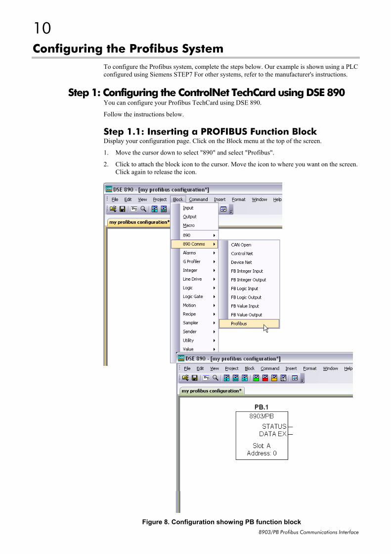
Step 1.1: Inserting a PROFIBUS Function BlockDisplay your configuration page. Click on the Block menu at the top of the screen.
1. Move the cursor down to select "890" and select "Profibus".
2. Click to attach the block icon to the cursor. Move the icon to where you want on the screen.Click again to release the icon.
Figure 8. Configuration showing PB function block
11
8903/PB Profibus Communications Interface
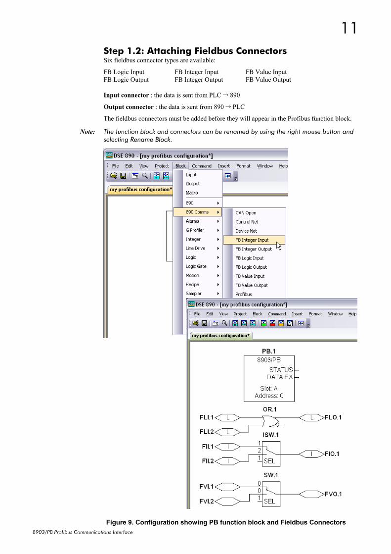
Step 1.2: Attaching Fieldbus ConnectorsSix fieldbus connector types are available:
FB Logic Input FB Integer Input FB Value InputFB Logic Output FB Integer Output FB Value Output
Input connector : the data is sent from PLC 890
Output connector : the data is sent from 890 PLC
The fieldbus connectors must be added before they will appear in the Profibus function block.
Note: The function block and connectors can be renamed by using the right mouse button andselecting Rename Block.
Figure 9. Configuration showing PB function block and Fieldbus Connectors
12
8903/PB Profibus Communications Interface
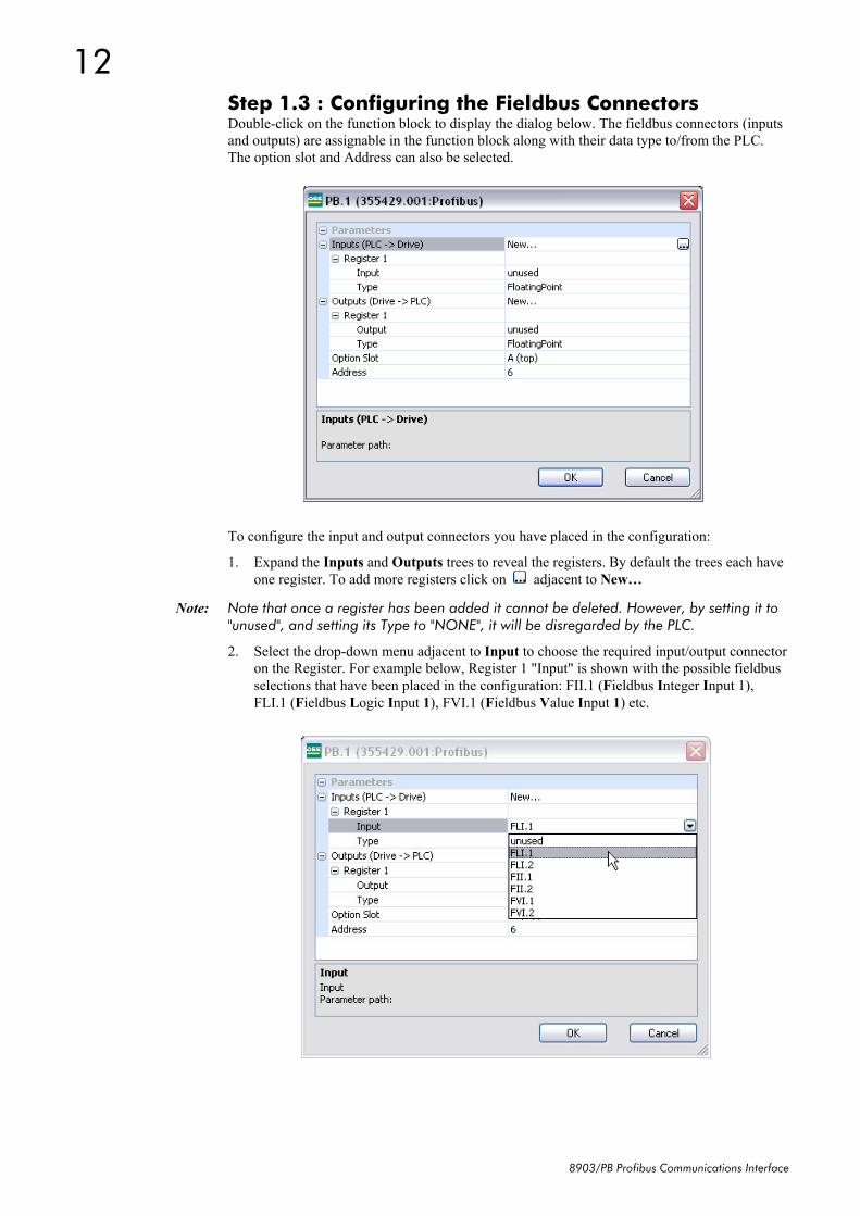
Step 1.3 : Configuring the Fieldbus ConnectorsDouble-click on the function block to display the dialog below. The fieldbus connectors (inputsand outputs) are assignable in the function block along with their data type to/from the PLC.The option slot and Address can also be selected.
To configure the input and output connectors you have placed in the configuration:
1. Expand the Inputs and Outputs trees to reveal the registers. By default the trees each haveone register. To add more registers click on adjacent to New…
Note: Note that once a register has been added it cannot be deleted. However, by setting it to"unused", and setting its Type to "NONE", it will be disregarded by the PLC.
2. Select the drop-down menu adjacent to Input to choose the required input/output connectoron the Register. For example below, Register 1 "Input" is shown with the possible fieldbusselections that have been placed in the configuration: FII.1 (Fieldbus Integer Input 1),FLI.1 (Fieldbus Logic Input 1), FVI.1 (Fieldbus Value Input 1) etc.
13
8903/PB Profibus Communications Interface
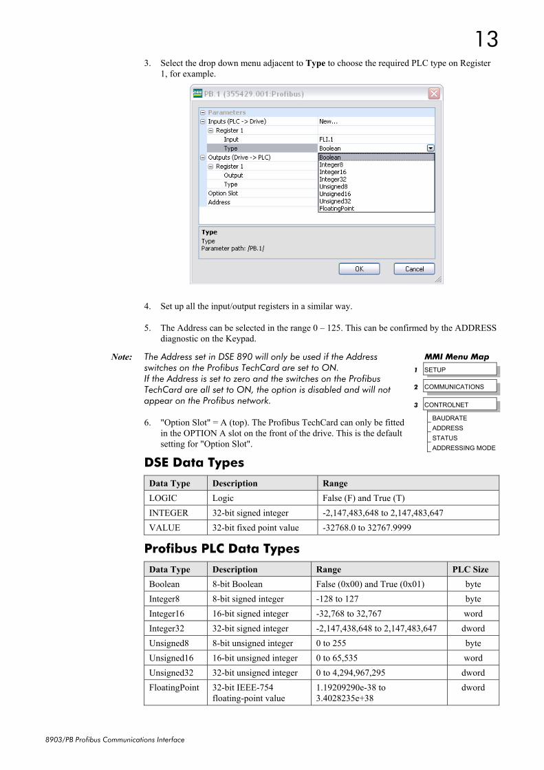
3. Select the drop down menu adjacent to Type to choose the required PLC type on Register1, for example.
4. Set up all the input/output registers in a similar way.
5. The Address can be selected in the range 0 – 125. This can be confirmed by the ADDRESSdiagnostic on the Keypad.
Note: The Address set in DSE 890 will only be used if the Addressswitches on the Profibus TechCard are set to ON.If the Address is set to zero and the switches on the ProfibusTechCard are all set to ON, the option is disabled and will notappear on the Profibus network.
6. "Option Slot" = A (top). The Profibus TechCard can only be fittedin the OPTION A slot on the front of the drive. This is the defaultsetting for "Option Slot".
DSE Data Types
Data Type Description RangeLOGIC Logic False (F) and True (T)INTEGER 32-bit signed integer -2,147,483,648 to 2,147,483,647VALUE 32-bit fixed point value -32768.0 to 32767.9999
Profibus PLC Data Types
Data Type Description Range PLC SizeBoolean 8-bit Boolean False (0x00) and True (0x01) byteInteger8 8-bit signed integer -128 to 127 byteInteger16 16-bit signed integer -32,768 to 32,767 wordInteger32 32-bit signed integer -2,147,438,648 to 2,147,483,647 dwordUnsigned8 8-bit unsigned integer 0 to 255 byteUnsigned16 16-bit unsigned integer 0 to 65,535 wordUnsigned32 32-bit unsigned integer 0 to 4,294,967,295 dwordFloatingPoint 32-bit IEEE-754
Conversion of DSE Type < > Profibus TypeThe DSE fieldbus connectors are each assigned a Profibus PLC "Type" as described in "Step 1.3: Configuring the Fieldbus Connectors" on page 12.
The conversion between the DSE type and the PLC type is performed automatically (refer toAppendix B : DSE/Profibus Conversion Rules, page 21).
Any PLC type can be assigned to a fieldbus connector
Some recommended PLC type assignments to fieldbus connectors are given in the table below:
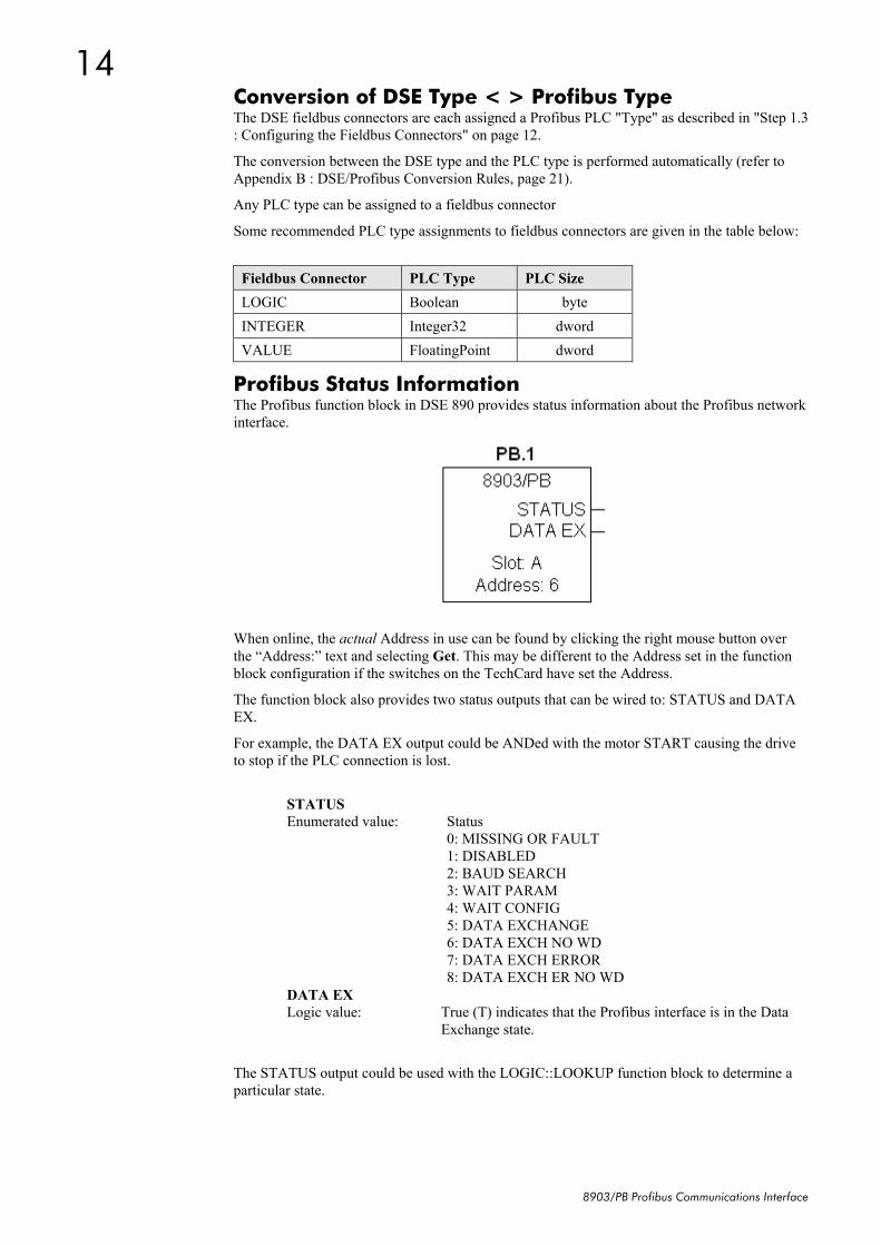
Profibus Status InformationThe Profibus function block in DSE 890 provides status information about the Profibus networkinterface.
When online, the actual Address in use can be found by clicking the right mouse button overthe “Address:” text and selecting Get. This may be different to the Address set in the functionblock configuration if the switches on the TechCard have set the Address.
The function block also provides two status outputs that can be wired to: STATUS and DATAEX.
For example, the DATA EX output could be ANDed with the motor START causing the driveto stop if the PLC connection is lost.
STATUSEnumerated value: Status
0: MISSING OR FAULT1: DISABLED2: BAUD SEARCH3: WAIT PARAM4: WAIT CONFIG5: DATA EXCHANGE6: DATA EXCH NO WD7: DATA EXCH ERROR8: DATA EXCH ER NO WD
DATA EXLogic value: True (T) indicates that the Profibus interface is in the Data
Exchange state.
The STATUS output could be used with the LOGIC::LOOKUP function block to determine aparticular state.
15
8903/PB Profibus Communications Interface
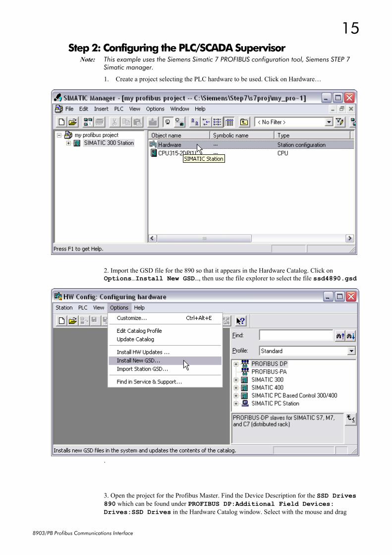
Step 2: Configuring the PLC/SCADA SupervisorNote: This example uses the Siemens Simatic 7 PROFIBUS configuration tool, Siemens STEP 7
Simatic manager.
1. Create a project selecting the PLC hardware to be used. Click on Hardware…
2. Import the GSD file for the 890 so that it appears in the Hardware Catalog. Click onOptions…Install New GSD…, then use the file explorer to select the file ssd4890.gsd
.
3. Open the project for the Profibus Master. Find the Device Description for the SSD Drives890 which can be found under PROFIBUS DP:Additional Field Devices:Drives:SSD Drives in the Hardware Catalog window. Select with the mouse and drag
16
8903/PB Profibus Communications Interface
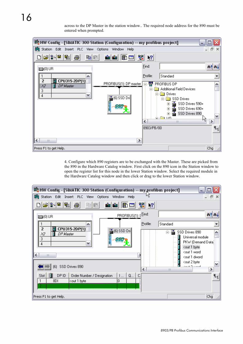
across to the DP Master in the station window.. The required node address for the 890 must beentered when prompted.
4. Configure which 890 registers are to be exchanged with the Master. These are picked fromthe 890 in the Hardware Catalog window. First click on the 890 icon in the Station window toopen the register list for this node in the lower Station window. Select the required module inthe Hardware Catalog window and then click or drag to the lower Station window.
17
8903/PB Profibus Communications Interface
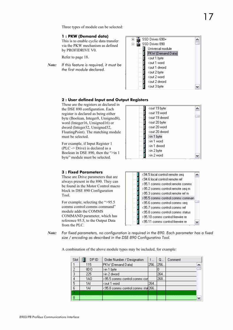
Three types of module can be selected:
1 : PKW (Demand data)This is to enable cyclic data transfervia the PKW mechanism as definedby PROFIDRIVE V0.
Refer to page 18.
Note: If this feature is required, it must bethe first module declared.
2 : User defined Input and Output RegistersThese are the registers as declared inthe DSE 890 configuration. Eachregister is declared as being eitherbyte (Boolean, Integer8, Unsigned8),word (Integer16, Unsigned16) ordword (Integer32, Unsigned32,FloatingPoint). The matching modulemust be selected.
For example, if Input Register 1(PLC -> Drive) is declared as aBoolean in DSE 890, then the “>in 1byte” module must be selected.
3 : Fixed ParametersThese are Drive parameters that arealways present in the 890. They canbe found in the Motor Control macroblock in DSE 890 ConfigurationTool.
For example, selecting the “>95.5comms control:comms command”module adds the COMMSCOMMAND parameter, which hasreference 95.5, to the Output Datafrom the PLC.
Note: For fixed parameters, no configuration is required in the 890. Each parameter has a fixedsize / encoding as described in the DSE 890 Configuratino Tool.
A combination of the above module types may be included, for example:
18
8903/PB Profibus Communications Interface
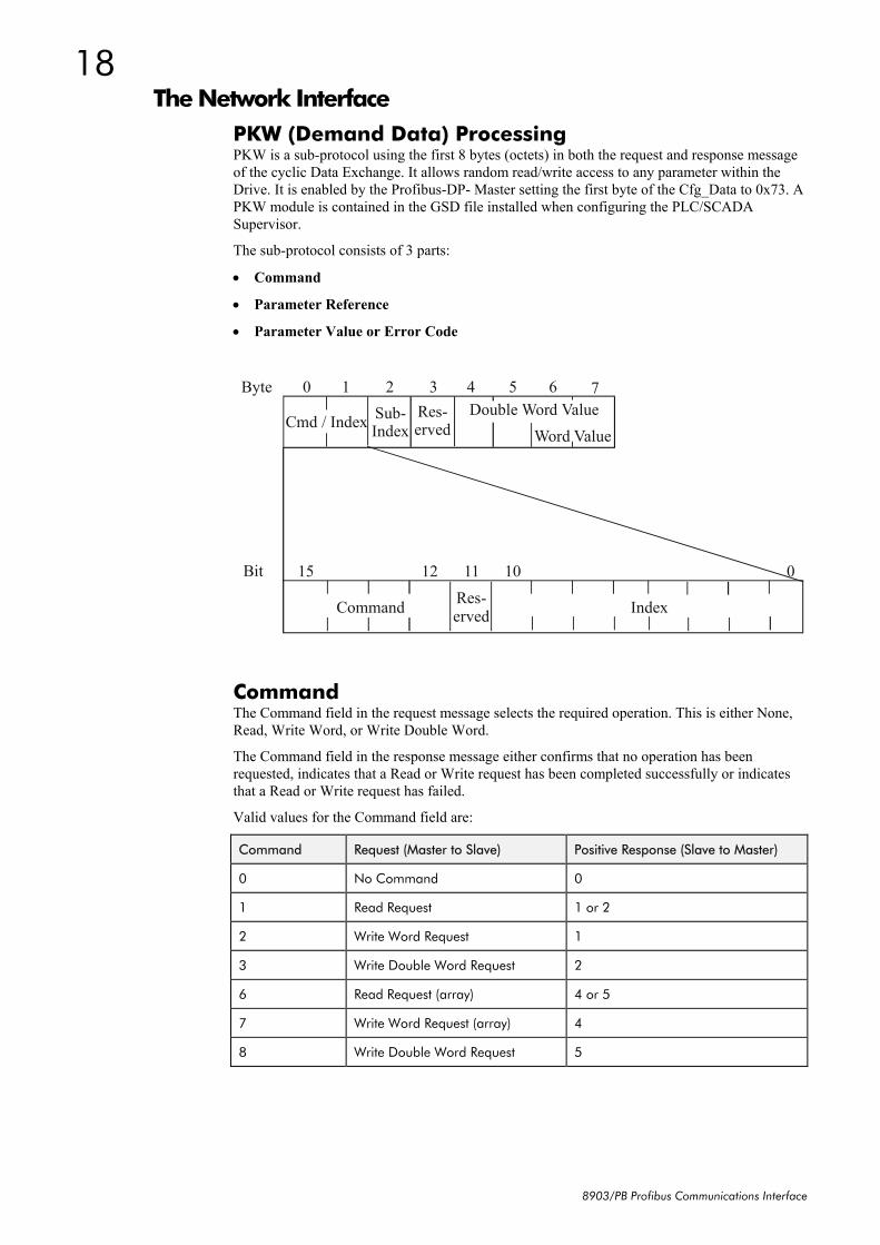
The Network InterfacePKW (Demand Data) ProcessingPKW is a sub-protocol using the first 8 bytes (octets) in both the request and response messageof the cyclic Data Exchange. It allows random read/write access to any parameter within theDrive. It is enabled by the Profibus-DP- Master setting the first byte of the Cfg_Data to 0x73. APKW module is contained in the GSD file installed when configuring the PLC/SCADASupervisor.
The sub-protocol consists of 3 parts:
• Command
• Parameter Reference
• Parameter Value or Error Code
Byte 0 1 2 3 4 5 6 7 Res-erved Cmd / Index
Word Value
011 12 15 Bit
Command Index
10
Sub-Index
Res-erved
Double Word Value
CommandThe Command field in the request message selects the required operation. This is either None,Read, Write Word, or Write Double Word.
The Command field in the response message either confirms that no operation has beenrequested, indicates that a Read or Write request has been completed successfully or indicatesthat a Read or Write request has failed.
Valid values for the Command field are:
Command Request (Master to Slave) Positive Response (Slave to Master)
0 No Command 0
1 Read Request 1 or 2
2 Write Word Request 1
3 Write Double Word Request 2
6 Read Request (array) 4 or 5
7 Write Word Request (array) 4
8 Write Double Word Request 5
19
8903/PB Profibus Communications Interface
The valid Response Codes are:
Response Meaning
0 No Response
1 Transfer Word
2 Transfer Double Word
4 Transfer Word (array)
5 Transfer Double Word (array)
7 Request Rejected with error code
Parameter ReferenceThe Parameter Reference consists of an Index and a Sub-Index:
♦ For User Defined Input Registers, the Index is 254 and the Sub-Index is the Input RegisterNumber
♦ For User Defined Output Registers, the Index is 254 and the Sub-Index is the OutputRegister Number
♦ For Fixed Parameters, the Index is the "Block" number and the Sub-Index is the"Parameter" number. These are listed in the GDS file, in the DSE Configuration Tool, orcan be displayed on the MMI by holding the "M" key for a few seconds whilst displayingthe parameter (PREF).
Parameter Value or Error CodeThe Value/Error Code field is used to receive a Read value, send a Write value or receive anerror code.
The Value is either a Word (16-bit) or a Double Word (32-bit):
♦ If a Word, the value is transferred in octets 6 and 7 of the request and/or response
♦ If a Double Word, the value is transferred in octets 4, 5, 6 and 7.
If the Response Command is 7, i.e. the request has been rejected, this field contains the errorcode. These are:
Error Code Meaning
0 Invalid Tag Number
1 Read Only Parameter
2 Value Under/Over-Range
3 Incorrect Data Type
17 Request cannot be processed because of operating state
18 Other error
20
8903/PB Profibus Communications Interface
Appendix A : Troubleshooting
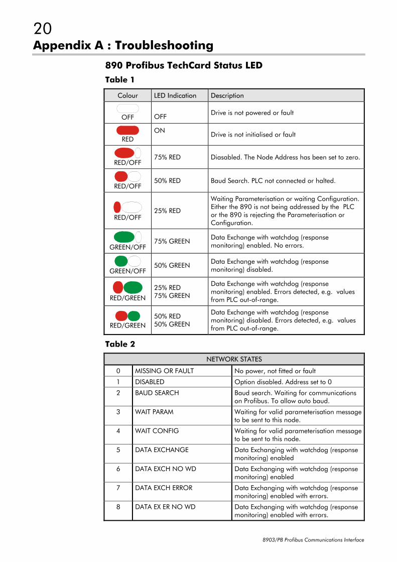
890 Profibus TechCard Status LEDTable 1
Colour LED Indication Description
OFF OFF Drive is not powered or fault
REDON Drive is not initialised or fault
RED/OFF75% RED Diasabled. The Node Address has been set to zero.
RED/OFF50% RED Baud Search. PLC not connected or halted.
RED/OFF25% RED
Waiting Parameterisation or waiting Configuration.Either the 890 is not being addressed by the PLCor the 890 is rejecting the Parameterisation orConfiguration.
GREEN/OFF75% GREEN Data Exchange with watchdog (response
monitoring) enabled. No errors.
GREEN/OFF50% GREEN Data Exchange with watchdog (response
monitoring) disabled.
RED/GREEN
25% RED75% GREEN
Data Exchange with watchdog (responsemonitoring) enabled. Errors detected, e.g. valuesfrom PLC out-of-range.
RED/GREEN50% RED50% GREEN
Data Exchange with watchdog (responsemonitoring) disabled. Errors detected, e.g. valuesfrom PLC out-of-range.
Table 2
NETWORK STATES
0 MISSING OR FAULT No power, not fitted or fault
1 DISABLED Option disabled. Address set to 0
2 BAUD SEARCH Baud search. Waiting for communicationson Profibus. To allow auto baud.
3 WAIT PARAM Waiting for valid parameterisation messageto be sent to this node.
4 WAIT CONFIG Waiting for valid parameterisation messageto be sent to this node.
5 DATA EXCHANGE Data Exchanging with watchdog (responsemonitoring) enabled
6 DATA EXCH NO WD Data Exchanging with watchdog (responsemonitoring) enabled
7 DATA EXCH ERROR Data Exchanging with watchdog (responsemonitoring) enabled with errors.
8 DATA EX ER NO WD Data Exchanging with watchdog (responsemonitoring) enabled with errors.
21
8903/PB Profibus Communications Interface
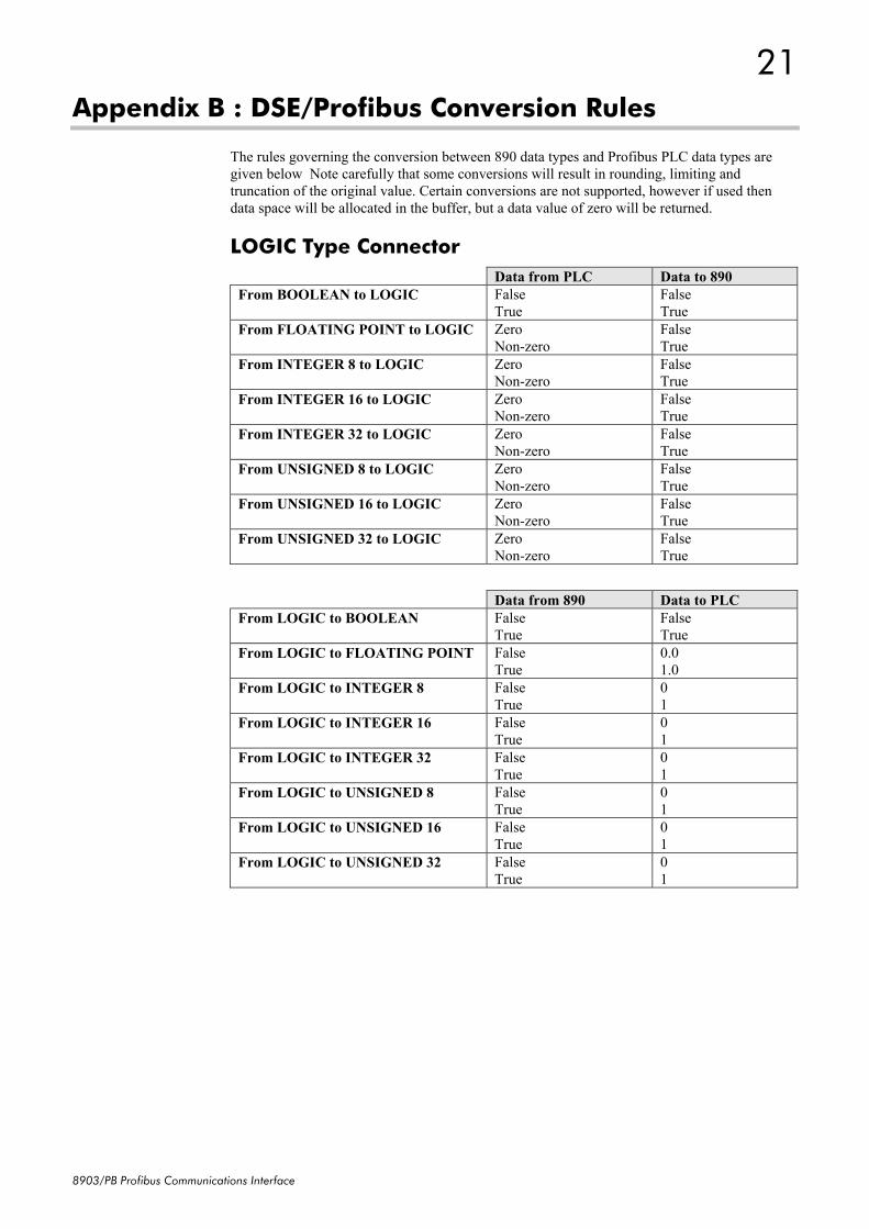
Appendix B : DSE/Profibus Conversion Rules
The rules governing the conversion between 890 data types and Profibus PLC data types aregiven below Note carefully that some conversions will result in rounding, limiting andtruncation of the original value. Certain conversions are not supported, however if used thendata space will be allocated in the buffer, but a data value of zero will be returned.
LOGIC Type ConnectorData from PLC Data to 890
From BOOLEAN to LOGIC FalseTrue
FalseTrue
From FLOATING POINT to LOGIC ZeroNon-zero
FalseTrue
From INTEGER 8 to LOGIC ZeroNon-zero
FalseTrue
From INTEGER 16 to LOGIC ZeroNon-zero
FalseTrue
From INTEGER 32 to LOGIC ZeroNon-zero
FalseTrue
From UNSIGNED 8 to LOGIC ZeroNon-zero
FalseTrue
From UNSIGNED 16 to LOGIC ZeroNon-zero
FalseTrue
From UNSIGNED 32 to LOGIC ZeroNon-zero
FalseTrue
Data from 890 Data to PLCFrom LOGIC to BOOLEAN False
TrueFalseTrue
From LOGIC to FLOATING POINT FalseTrue
0.01.0
From LOGIC to INTEGER 8 FalseTrue
01
From LOGIC to INTEGER 16 FalseTrue
01
From LOGIC to INTEGER 32 FalseTrue
01
From LOGIC to UNSIGNED 8 FalseTrue
01
From LOGIC to UNSIGNED 16 FalseTrue
01
From LOGIC to UNSIGNED 32 FalseTrue
01
22
8903/PB Profibus Communications Interface
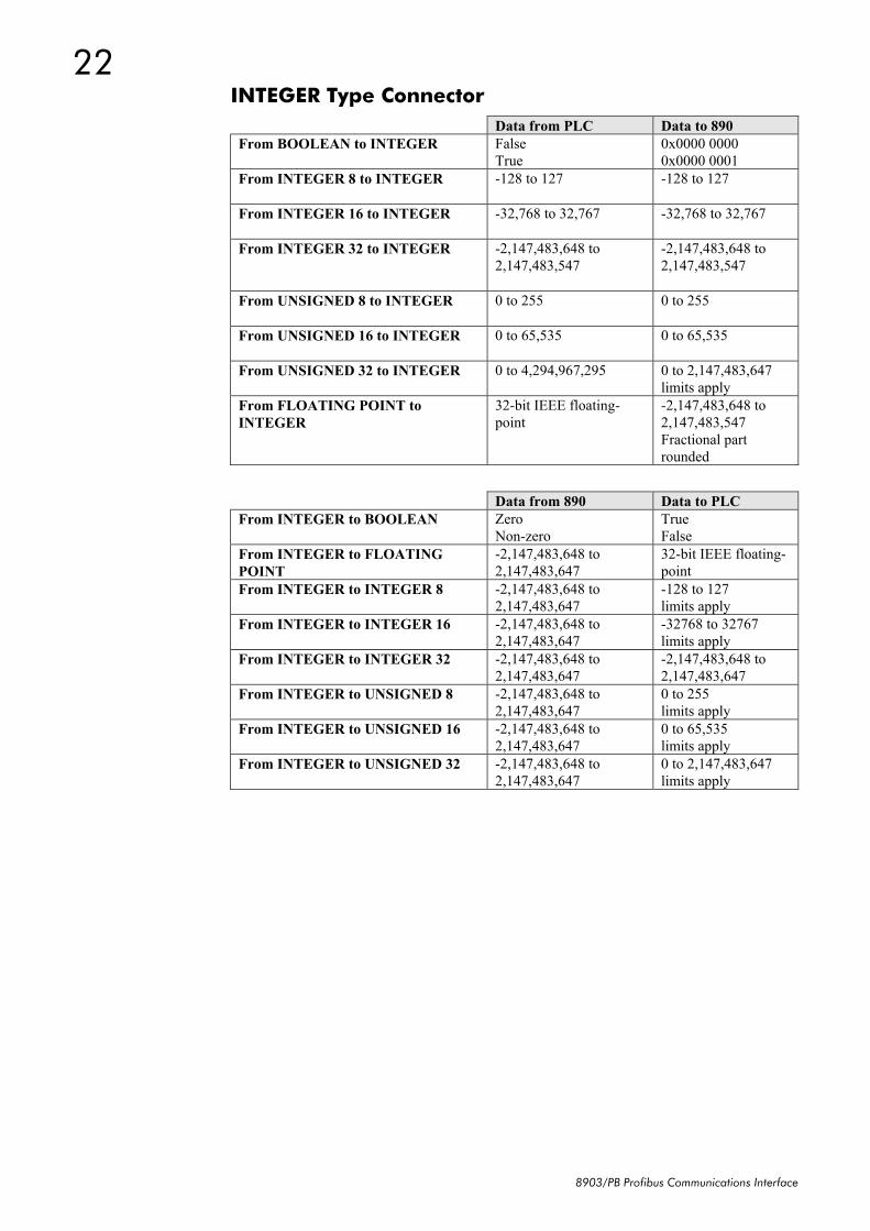
INTEGER Type ConnectorData from PLC Data to 890
From BOOLEAN to INTEGER FalseTrue
0x0000 00000x0000 0001
From INTEGER 8 to INTEGER -128 to 127 -128 to 127
From INTEGER 16 to INTEGER -32,768 to 32,767 -32,768 to 32,767
From INTEGER 32 to INTEGER -2,147,483,648 to2,147,483,547
-2,147,483,648 to2,147,483,547
From UNSIGNED 8 to INTEGER 0 to 255 0 to 255
From UNSIGNED 16 to INTEGER 0 to 65,535 0 to 65,535
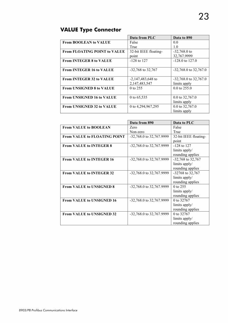
From UNSIGNED 32 to INTEGER 0 to 4,294,967,295 0 to 2,147,483,647limits apply