IEEE TRANSACTIONS ON BROADCASTING. VOL. 31. NO. I. MARCH 199.5 9 A Comparison of QAM and VSB for Hybrid FiberKOax Digital Transmission Carrier recovery K. J. Kerpez BELLCORE, 445 South Street, Morristown, NJ 07960 demodulator pilot tone and PLYd data-directed loop, blind Abshmct - There are two competing trarrsmission system for downst” digital tmnsmission on hybrid fibedcoax cable netwolks: quad” amplitude modulation (QAM), and vestigial sideband modulation (VSB). Both QAM and VSB are bandwidth efficient, and have the same bandwidth efficiency. Detailed calculaliom and simulatiom of QAM and VSB trarrsmission on hybrid fibedcoax are reported here. It is shown ht, since VSB has a higher symbol mfe, it has at most l/2 dB less wived SNR than QAM at low frequencies because of dispexsion and symbol timing jitter. 'Ibis difference is negligible. Vendon pmposing VSB mcover the canierwith a pilot tone and a PLI, and vendors proposing QAM use all-digital data-dkted canier mcovery. Simulations reported here show that QAM and VSB have very similar der movery performance. It is concluded ihat for hybrid fibedcoax, VSB and QAM have practically liK sarne overall performance, and the choice between lime hnsmission system should be based on considerations other than performance. ReauiredSNR I > 0 dB I. INTRODUCTION > 18dB Hybrid fiberkoax is an emerging architecture for providing residential video and digital access. It has optical fibers extending from the head-end or central office to remote fiber nodes. Extending from the fiber nodes is a coaxial cable distribution system that serves between a hundred and a thousand residences. Signals can be modulated and multiplexed at the head-end, transmitted by linear lasers in analog format on the fiber, then linearly converted to electrical signals for transmission on the coax. This architecture advantageously combines the long range of optical fiber with the simple electrical interfaces of coaxial cable. Hybrid fiberkoax can cany multiple digital TV channels in the bandwidth currently used for a single analog TV channel. Digital signals can also support a variety of future services. There are two modulation techniques, quadrature amplitude modulation (QAM) and vestigial sideband modulation (VSB), that have emerged as the major contenders for downstream digital transmission on hybrid fiberkoax. Both modulations are bandwidth efficient and use multiple signal levels to send multiple bits/Hz. VSB conserves bandwidth by only transmitting a single sideband of the modulated RF spectrum [l]. QAM conserves bandwidth by sending two orthogonal sine and cosine carriers in the same frequency band. VSB is currently used for analog NTSC TV. VSB is likely to become the HDTV standard, [2] since it had better test results than QAM for terrestrial HDTV broadcast. Zenith [3] has advanced VSB for future digital cable TV. QAM is widely used in satellite, microwave, computer, and telephone modems. QAM is proposed for tibedcoax transmission systems by Broadcom [4], Jerrold [5], AT&T, for acquisition Acquisition speed Symbol rate Information bit rate Scientific-Atlanta, and others. AT&T uses a clever implementation of QAM called carrierless AM-PM (CAP).[6] Proponents of the two systems have made conflicting claims. [3][4] To help resolve these claims, the performance of QAM and VSB on hybrid fibedcoax is calculated in detail and compared here. Implementations, vendor solutions, and complexity, are also impartially compared. It is concluded that, although the two systems are incompatible and have many differences, their performance and inherent costs are very similar for hybrid fiber coax networks. about 1 second (improving) 10.76 Mbaud 5 Mbaud 38.6 Mbit/s 27 Mbit/s for 64-QAM, 36 Mbit/s for 0.1 to 0.2 seconds 256-QAM TABLE I Comparison of Proposed VSB and QAM Transmission System Parameters. I I 16 - VSB I 64,256-QAM 1 I I Timing recovery I aided by segment I data-directed loop, Table I lists major differences between vendor implementations of QAM and VSB. Acquisition speeds, acquisition SNRs, and information rates were obtained from references. [2][4][7] The information rate is the transmitted bit rate minus overhead. Section I1 of this paper discusses the relationship between bandwidth, SNR, and bit rate. Table 11 shows that the ideal required SNR is very sensitive to the number of signal levels and bit rate, but is invariant with respect to QAM or VSB. Section I n discusses cable distortion and symbol timing jitter. It is shown that, that since VSB has a 00 18-93 16/9.5$04.00 0 I995 IEEE
Transcript
IEEE TRANSACTIONS ON BROADCASTING. VOL. 31. NO. I . MARCH 199.5 9
A Comparison of QAM and VSB for Hybrid FiberKOax Digital Transmission
Carrier recovery
K. J. Kerpez BELLCORE, 445 South Street, Morristown, NJ 07960
demodulator pilot tone and PLYd data-directed loop,
blind
Abshmct - There are two competing trarrsmission system for downst” digital tmnsmission on hybrid fibedcoax cable netwolks: quad” amplitude modulation (QAM), and vestigial sideband modulation (VSB). Both QAM and VSB are bandwidth efficient, and have the same bandwidth efficiency. Detailed calculaliom and simulatiom of QAM and VSB trarrsmission on hybrid fibedcoax are reported here. It is shown h t , since VSB has a higher symbol mfe, it has at most l/2 dB less w i v e d SNR than QAM at low frequencies because of dispexsion and symbol timing jitter. 'Ibis difference is negligible. Vendon pmposing VSB mcover the canier with a pilot tone and a PLI, and vendors proposing QAM use all-digital data-dkted canier mcovery. Simulations reported here show that QAM and VSB have very similar d e r movery performance. It is concluded ihat for hybrid fibedcoax, VSB and QAM have practically liK sarne overall performance, and the choice between lime hnsmission system should be based on considerations other than performance.
ReauiredSNR I > 0 dB
I. INTRODUCTION
> 18dB
Hybrid fiberkoax is an emerging architecture for providing residential video and digital access. It has optical fibers extending from the head-end or central office to remote fiber nodes. Extending from the fiber nodes is a coaxial cable distribution system that serves between a hundred and a thousand residences. Signals can be modulated and multiplexed at the head-end, transmitted by linear lasers in analog format on the fiber, then linearly converted to electrical signals for transmission on the coax. This architecture advantageously combines the long range of optical fiber with the simple electrical interfaces of coaxial cable.
Hybrid fiberkoax can cany multiple digital TV channels in the bandwidth currently used for a single analog TV channel. Digital signals can also support a variety of future services. There are two modulation techniques, quadrature amplitude modulation (QAM) and vestigial sideband modulation (VSB), that have emerged as the major contenders for downstream digital transmission on hybrid fiberkoax. Both modulations are bandwidth efficient and use multiple signal levels to send multiple bits/Hz. VSB conserves bandwidth by only transmitting a single sideband of the modulated RF spectrum [l]. QAM conserves bandwidth by sending two orthogonal sine and cosine carriers in the same frequency band.
VSB is currently used for analog NTSC TV. VSB is likely to become the HDTV standard, [2] since it had better test results than QAM for terrestrial HDTV broadcast. Zenith [3] has advanced VSB for future digital cable TV. QAM is widely used in satellite, microwave, computer, and telephone modems. QAM is proposed for tibedcoax transmission systems by Broadcom [4], Jerrold [5], AT&T,
for acquisition Acquisition speed
Symbol rate Information bit
rate
Scientific-Atlanta, and others. AT&T uses a clever implementation of QAM called carrierless AM-PM (CAP).[6] Proponents of the two systems have made conflicting claims. [3][4] To help resolve these claims, the performance of QAM and VSB on hybrid fibedcoax is calculated in detail and compared here. Implementations, vendor solutions, and complexity, are also impartially compared. It is concluded that, although the two systems are incompatible and have many differences, their performance and inherent costs are very similar for hybrid fiber coax networks.
about 1 second (improving)
10.76 Mbaud 5 Mbaud 38.6 Mbit/s 27 Mbit/s for
64-QAM, 36 Mbit/s for
0.1 to 0.2 seconds
256-QAM
TABLE I Comparison of Proposed VSB and QAM Transmission
System Parameters.
I I 16 - VSB I 64,256-QAM 1
I I
Timing recovery I aided by segment I data-directed loop,
Table I lists major differences between vendor implementations of QAM and VSB. Acquisition speeds, acquisition SNRs, and information rates were obtained from references. [2][4][7] The information rate is the transmitted bit rate minus overhead.
Section I1 of this paper discusses the relationship between bandwidth, SNR, and bit rate. Table 11 shows that the ideal required SNR is very sensitive to the number of signal levels and bit rate, but is invariant with respect to QAM or VSB. Section I n discusses cable distortion and symbol timing jitter. It is shown that, that since VSB has a
00 18-93 16/9.5$04.00 0 I995 IEEE
I O
higher symbol rate, it can have up to 0.5 dB less received SNR than QAM at low frequencies because of cable distortion and jitter. Section IV shows that QAM and VSB equalizers each perform about the same number of computations per second, but the QAM equalizer has a somewhat more complicated configuration than the VSB equalizer. Proposed VSB systems use pilot tones for carrier recovery, and proposed QAM systems use data- driven carrier recovery. However, both QAM and VSB could use either technique. Section V and the appendices show that QAM and VSB have practically the same carrier recovery performance.
11. BANDWIDTH EFFICIENCY
QAM and VSB have essentially the same bandwidth efficiency, which can be expressed by the number of data bits/Hz that the modulation carries. QAM conserves bandwidth by sending two dimensional signals on orthogonal cosine (in-phase) and sine (quadrature) carriers, which have the same frequency but a 90" phase difference. VSB conserves bandwidth by only transmitting one of the two sidebands of the in-phase channel. [I]
A A
VSB QAM Fig. 1. VSB and QAM spectra and carriers.
TABLE II VSB and QAM Spectral Efficiency and Required SNR.
I bits/Hz I min SNR. I # o f O M I #of VSB 1
The signal to noise ratio (SNR) required for VSB and QAM to achieve a bit error rate was precisely calculated and is shown in Table 11. For a fixed number of bitsMz, it was found that the ideal required SNRs for QAM and VSB on a flat channel differed by less than 0.02 dB. Given a 6 M H Z TV channel, VSB with 11.5% excess bandwidth has a 10.76 Mbaud symbol rate with 0.093 microsecond symbols. QAM with 20% excess bandwidth has a 5.0 Mbaud symbol rate with 0.2 microsecond symbols. For downstream transmission, highly bandwidth efficient modulation is appropriate, such as 64 or 256-point QAM, and 8 or 16-level VSB. 16-VSB with 11.5% excess bandwidth carries 43 Mbit/s in 6 MHz, and 64-QAM with 20% excess bandwidth carries 30 Mbit/s, including overhead. Four point QAM (QPSK) is robust (it is widely
used in mobile radio) and it has been proposed for upstream transmission. As shown in Table 11, QAM is a little more flexible than VSB since it can transmit an odd number of bits per Hz.
ID. CABLE DISTORTION, ATTENUATION AND JITTER
Coaxial cable is the communications bottleneck of hybrid fiberkoax. This section outlines detailed calculations of the received SNR with QAM and VSB transmitted over coaxial cable. The symbol rate of QAM is half the symbol rate of VSB, assuming constant RF bandwidth. T h s would be a drawback for VSB on highly dispersive channels such as copper twisted pairs. It is shown here that coaxial cable has little dispersion and the difference in symbol rates has only a minor effect. Results here are for the "worst-case" subscriber, who is located about one half mile from the fiber node or the last amplifier, and has worst case noise.
The simulated received white noise power has a worst case value = -33 dBmV. The transmitted power of the digital signal is assumed to be 30 dBmV, which is low enough to limit intermodulation products in the NTSC TV bands. [5] At the output of the transmitter, the SNR = 30 dBmV - -33 dBmV = 63 dB. The SNR at the downstream digital receiver = 63 dB - the decrease in signal power due to cable loss. Assuming about two levels of splitters per distribution tree, because of noise funneling the noise on the upstream is 6 dB higher than it is on the downstream. Thus for upstream calculations, the SNR at the output of the transmitter = 57 dB. The impulse response of 2750 feet of 3/4" coaxial cable was calculated with the equations given by Wigington and Nahman. [8]
It is assumed that the transmit pulse is a raised-cosine pulse with excess bandwidth a. For QAM, raised-cosine pulses of period Tare modulated by cosine and sine carriers at rate 1/T, using bandwidth (1 + a ) / T and center frequency fc. The QAM carrier is at the center of the transmitted RF spectrum. The QAM signals are demodulated by carrier fc and sampled at a 1/T sampling rate.
Assuming that a symmetric phasing filter is used to generate the VSB signal, the same raised-cosine spectrum transmitted by the QAM in-phase channel is transmitted by VSB, as shown on page 153 of Haykin. [ l ] Here fc denotes the center frequency of the VSB signal, its carrier is at the lower band-edge of the transmitted RF spectrum, fc - I/( 2 T ) . The VSB signal is demodulated by frequency fc - 1 / (2T) and sampled at a 2/Tsampling rate. For the QAM and VSB calculations here the excess bandwidth is 11.5%, which is proposed for HDTV. [2] A 6 MHz channel is assumed.
A closed form expression for spectrum of the received pulse response was found. This expression includes the raised-cosine pulse, baseband to RF modulation, coax channel, and demodulation. This spectrum was then numerically evaluated by an IFFT to get the time domain pulse response. All simulations use linear finite impulse response (FIR) tapped-delay line equalizers. Minimum mean squared error baud-spaced linear equalizer taps [9] were computed from the sampled pulse response and noise spectrum. The FIR filters of the equalizers here each have 63 baud-spaced taps, where QAM taps are complex. Equalizer complexity will be discussed in Section IV.
100 200 300 400 500 600 700 800
Mid-band frequency, fc (MHz)
Transmit pulse
Number of eaualizer tam
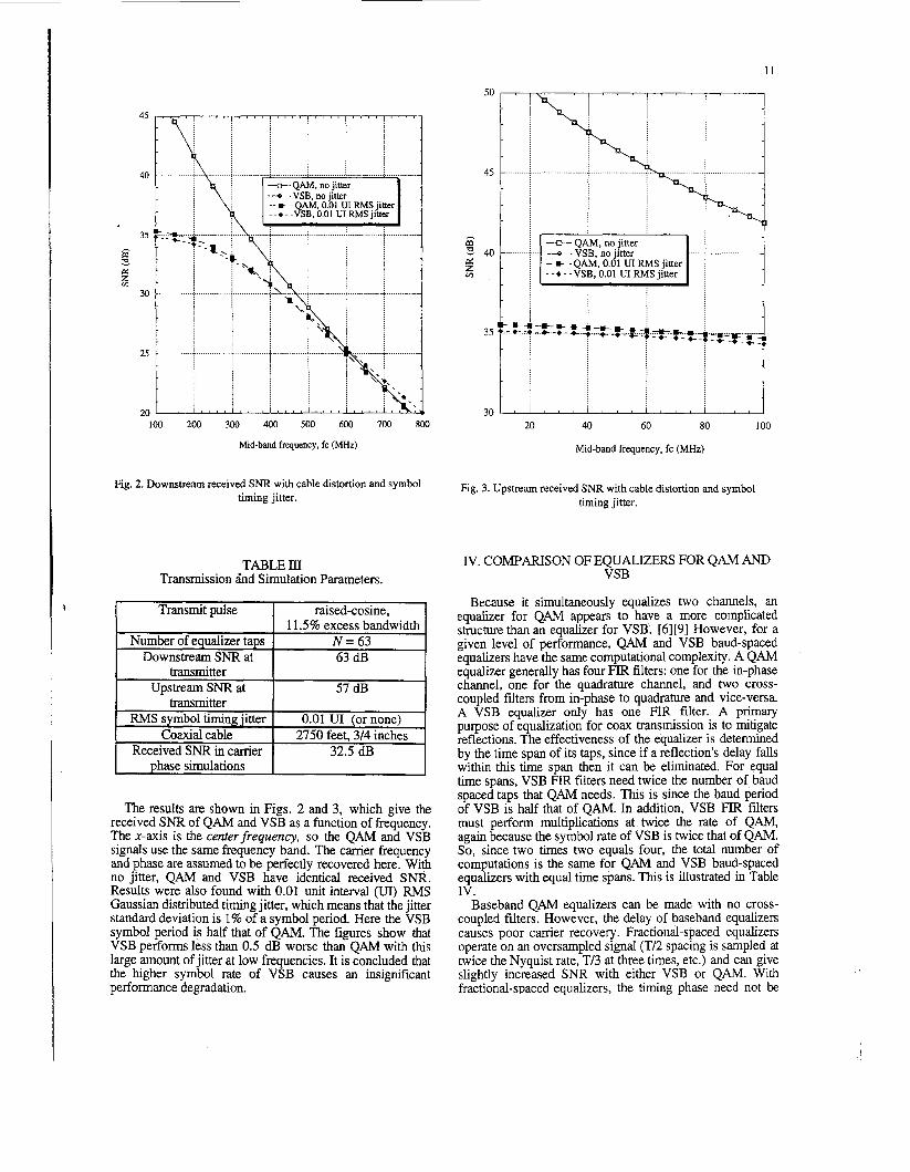
Fig. 2. Downstream received S N R with cable distortion and symbol timing jitter.
raised-cosine, 1 1.5% excess bandwidth
N = 63
TABLE III Transmission ind Simulation Parameters.
Downstream S N R at transmitter
Upstream S N R at
63 dB
57 dB transmitter
FWS symbol timing jitter Coaxial cable
0.01 U1 (or none) 2750 feet. 314 inches
Received SNR in carrier phase simulations
The results are shown in Figs. 2 and 3, which give the received S N R of QAM and VSB as a function of frequency. The x-axis is the centerfrequency, so the QAM and VSB signals use the same frequency band. The carrier frequency and phase are assumed to be perfectly recovered here. With no jitter, QAM and VSB have identical received SNR. Results were also found with 0.01 unit interval (UI) RMS Gaussian distributed timing jitter, which means that the jitter standard deviation is 1% of a symbol period. Here the VSB symbol period is half that of QAM. The figures show that VSB performs less than 0.5 dB worse than QAM with this large amount of jitter at low frequencies. It is concluded that the higher symbol rate of VSB causes an insignificant performance degradation.
, ~ ~~~ ~ ~ - -
32.5 dB
.......... ............................... rx
Fig. 3. Upstream received S N R with cable distortion and symbol timing jitter.
IV. COMPARISON OF EQUALIZERS FOR QAM AND VSB
Because it simultaneously equalizes two channels, an equalizer for QAM appears to have a more complicated structure than an equalizer for VSB. [6][9] However, for a given level of performance, QAM and VSB baud-spaced equalizers have the same computational complexity. A QAM equalizer generally has four FIR filters: one for the in-phase channel, one for the quadrature channel, and two cross- coupled filters from in-phase to quadrature and vice-versa. A VSB equalizer only has one FIR filter. A primary purpose of equalization for coax transmission is to mitigate reflections. The effectiveness of the equalizer is determined by the time span of its taps, since if a reflection's delay falls within this time span then it can be eliminated. For equal time spans, VSB FIR filters need twice the number of baud spaced taps that QAM needs. This is since the baud period of VSB is half that of QAM. In addition, VSB FIR filters must perform multiplications at twice the rate of QAM, again because the symbol rate of VSB is twice that of QAM. So, since two times two equals four, the total number of computations is the same for QAM and VSB baud-spaced equalizers with equal time spans. This is illustrated in Table IV .
Baseband QAM equalizers can be made with no cross- coupled filters. However, the delay of baseband equalizers causes poor carrier recovery. Fractional-spaced equalizers operate on an oversampled signal (T/2 spacing is sampled at twice the Nyquist rate, T/3 at three times, etc.) and can give slightly increased SNR with either VSB or QAM. With fractional-spaced equalizers, the timing phase need not be
I ? _
explicitly recovered. AT&T's CAP has a passband QAM equalizer with no cross-coupled filters and two fractional- spaced (typically T/4) FIR filters. Fractional-spaced equalizers are more complicated than baud-spaced equalizers.
\
TABLE IV Comparison of Equalizer Complexity.
T = QAM Baud Period.
QAM I VSB baud period = T I baud period = T L N/2 taps per sub channel, T baud-spaced time span = NTB
N taps, TE baud-spaced time span = N T L
Multiplications / second = N/T (no cross-coupled filters)
Zenith's current VSB proposal adapts the equalizer with the synchronization sequence, resulting in slow but robust adaptation. Broadcom's QAM proposal adapts the equalizers blindly on the data sequence, resulting in fast adaptation but requiring a relatively high SNR for convergence. However, Zenith is currently working on blind equalization for VSB.
V. CARRIER RECOVERY
With digital modulation, the carrier frequency and phase must be accurately estimated from the received signal. There are significant differences in the carrier recovery techniques proposed for QAh4 and VSB. This section outlines the prbposed carrier recovery techniques. Detailed simulations are reported. The results here show that carrier recovery techniques for QAM and VSB have practically identical performance.
A. Current vendor proposals
VSB, as proposed by Zenith, transmits a pilot tone at the carrier frequency, which is in the roll-off of the transmitted VSB signal. The pilot is easily made by adding a DC bias at baseband. The pilot increases the transmit signal power by 0.3 dB, resulting in an effective SNR loss of 0.3 dB. The pilot tone and carrier are recovered with a phase locked loop (PLL). [9] The PLL is an analog circuit. It acts as a very narrow-band bandpass filter that filters out almost everything except for the carrier. The Zenith receiver is proposed to use a wide-band (k100kHz) frequency and phase locked loop (FPLL) to acquire the carrier frequency, then a narrow-band (k2kHz) PLL to track the carrier phase. [2] QAM, as proposed by Broadcom [4] and others, uses
data-directed carrier recovery. Data-directed carrier recovery is implemented digitally. [9] The quantized estimates of the received data are fed back and combined with the received signal to update the carrier estimate. The proposed QAM
carrier recovery implementation operates "blindly" on the data stream. For data transmission at high SNR, data- directed carrier recovery has very low error and no overhead, so it has become the preferred technique for QAM
Broadcom reports that their blind data-directed carrier recovery technique achieves carrier acquisition with an S N R above 18 dB. [4] The pilot tone used with VSB reportedly achieves carrier acquisition with an SNR as low as 0 dB. [2][7] This was an asset for VSB in the terrestria1 broadcast environment of HDTV. However, it should make little difference in cable systems. The QAM system has no overhead, and the VSB pilot wastes 0.3 dB, which is again an inconsequential difference. QAM proponents claim that their all-digital carrier recovery techniques will be more cost effective when integrated into VLSI than the proposed analog FPLL of VSB. However, the FPLL is currently used in consumer TV receivers, and it is very inexpensive.
Ignoring current proposals, pilot tones are easily generated by adding a DC bias to the baseband data of either VSB or QAM, and they could be used with QAM as well as VSB. VSB has an advantage in that the pilot tone is in the signal band's roll-off, and it would also be harder to adapt to a QAM signal with a pilot tone since it is complex valued. If there is no pilot tone, then the carrier can still be recovered with a PLL by first passing the signal through a non-linearity, such as by squaring it, before the PLL. However, t h s non-linearity introduces phase ambiguity. Higher-order loop filters can increase performance. There are numerous other techniques for carrier recovery. [9][10]
B. Carrier recovery performance comparison
Detailed Monte-Carlo computer simulations incorporating carrier recovery techniques for QAM and VSB were developed. Systems with equal parameters were compared to isolate the generic difference between VSB and QAM with carrier recovery techniques. This section will calculate the performance of carrier recovery both for VSB with pilot tones and data-directed methods, and for QAM with pilot tones and data-directed methods. The performance of all systems was remarkably similar with the typical simulation parameters that were used. Also, the level of carrier recovery performance was well in excess of the minimum necessary. It can be concluded that carrier recovery is a total non-issue.
The simulations used the detailed channel model, equalizers, etc., described in Section 111. A downstream 6 MHz channel at a center frequency of 400 MHz with a received SNR of 32.5 dB was simulated. The simulations randomly generate QAM or VSB symbols, modulate and transmit them on the simulated coax channel. Then they are equalized and estimated by the receiver. A loop in the receiver estimates the carrier phase, which is used to simulate demodulation. Carrier frequency and symbol timing phase are known by the receiver.
The simulations with a PLL receiver had a pilot tone at the carrier frequency that added 0.3 dB to the signal power. The PLL is illustrated in Fig. 4. [9] [ 101 The simulated PLL loop filter was a first-order Butterworth filter with 3-dB point at 100 kHz. It was found that a 10 kHz 3-dB point had better performance, but it has less pull-in range and is not reported.
The data-directed carrier recovery simulations had no pilot. They used a first-order loop with no loop filter, as shown in Fig. 5. These simulations were allowed to initially
c Demodulated I channel
A 2~0~(2xfg + e,,)
7 P
Signal +noise
+ pilot, Asin(27rfci + €I(,)) i
estimated in-phase
signal
A sin(@(!) - &))+ signal + noise Demodulated Q channel v
Signal + noise -,
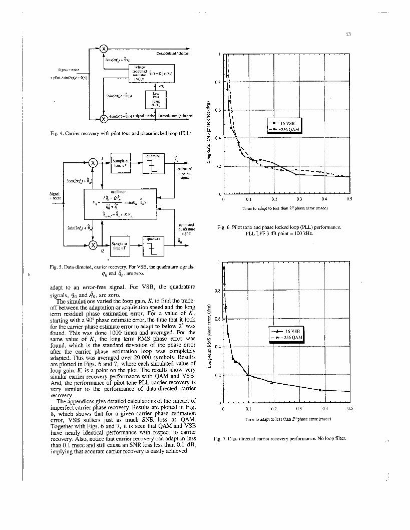
Fig. 4. Carrier recovery with pilot tone and phase locked loop (PLL).
oscillator I $ - Q ? v=- h
"I =sin@,- 0,) 411 + 'I1
A A
e,*+ I = 011 + K v,,
quantize
Fig. 5. Data-directed, carrier recovery. For VSB, the quadrature signals, qn and &, are zero.
estimated quadrature
signal A qn
adapt to an error-free signal. For VSB, the quadrature signals, qn and in, are zero.
The simulations varied the loop gain, K, to find the trade- off between the adaptation or acquisition speed and the long term residual phase estimation error. For a value of K , starting with a 90" phase estimate error, the time that it took for the carrier phase estimate error to adapt to below 2" was found. This was done 1000 times and averaged. For the same value of K , the long term RMS phase error was found, which is the standard deviation of the phase error after the carrier phase estimation loop was completely adapted. This was averaged over 20,000 symbols. Results are plotted in Figs. 6 and 7, where each simulated value of loop gain, K, is a point on the plot. The results show very similar carrier recovery performance with QAM and VSB. And, the performance of pilot tone-PLL carrier recovery is very similar to the performance of data-directed carrier recovery.
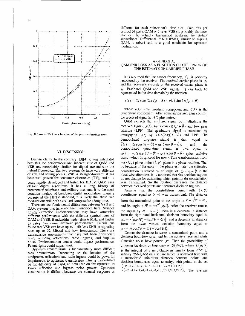
The appendices give detailed calculations of the impact of imperfect carrier phase recovery. Results are plotted in Fig. 8, which shows that for a given carrier phase estimation error, VSB suffers just as much SNR loss as QAM. Together with Figs. 6 and 7, it is seen that QAM and VSB have nearly identical performance with respect to carrier recovery. Also, notice that carrier recovery can adapt in less than 0.1 msec and still cause an SNR loss less than 0.1 dB, implying that accurate carrier recovery is easily achieved.
0 t__
I . . . I . . 0 . I - -
............. ...........
0 0. I 0.2 0.3 0.4 0.5
Time to adapt to less than 2O phase error (msec)
Fig. 6. Pilot tone and phase locked loop (PLL) performance. PLL LPF 3 dB point = 100 kHz.
0 0. I 0.2 0.3 0.4 0.5
Time to adapt to less than 2O phase error (msec)
Fig. 7. Data-directed carrier recovery performance. No loop filter.
--e 256 QAM : - * - 1 6 V S B 0.6 ............ ....,. .........
h z
0 0.2 0.4 0.6 0.8 1
Carrier phase error (deg)
Fig. 8. Loss in SNR as a function of the phase estimation error.
VI. DISCUSSION
Despite claims to the contrary, [3][4] it was calculated here that the performance and inherent cost of QAM and VSB are remarkably similar for digital transmission on hybrid fiberlcoax. The two systems do have very different origins and selling points. VSB is straight-forward, it has been well proven'for consumer electronics (TV), and it is being rapidly developed and tested for HDTV. QAM uses elegant digital algorithms, it has a long history of commercial telephone and military use, and it is the most common method of bandpass digital modulation. Largely because of the HDTV standard, it is llkely that these two modulations will both exist and compete for a long time.
There are less-fundamental differences between VSB and QAh4 systems that have not been mentioned here. Symbol timing extraction implementations may have somewhat different performance with the different symbol rates of QAM and VSB. Bandwidths wider than 6 MHz and higher bit rates can cause different performance. Calculations found that VSB can have up to 1 dB less SNR at signaling rates up to 52 Mbaud and low frequencies. There are transmission impairments that have not been considered here, including reflections, radio ingress, and impulse noise. Implementation details could impact performance. Patent rights could impact cost.
Upstream transmission is fundamentally more difficult than downstream. Depending on the location of the equipment, reflections and radio ingress could be powerful impairments to upstream transmission. This is exacerbated by the difficulty of using an equalizer on the upstream to lower reflection and ingress noise power. Upstream equalization is difficult because the channel response is
different for each subscriber's time slot. Two bits per symbol (4-point QAh4 or 2-level VSB) is probably the most that can be reliably transmitted upstream by distant subscribers. Differential PSK (DPSK), similar to 4-point QAM, is robust and is a good candidate for upstream modulation.
APPENDIX A: QAM SNR LOSS AS A FUNCTION OF THE ERROR OF
THE ESTIMATE OF CARRIER PHASE
It is assumed that the carrier frequency, f c , is perfectly recovered by the receiver. The received carrier phase is 0, and the receiver's estimate of the received carrier phase is 6 . Passband QAM and VSB signals [ l ] can both be represented in the time domain by the notation
y ( r ) = i(r)cos(2nfct + 8) + q(t)sin(2nfct + 0)
where i(t) is the in-phase component and q ( t ) is the quadrature component. After equalization and gain control, the received signal is ~ ( t ) plus noise.
QAM extracts the in-phase signal by multiplying the received signal, y ( t ) , by 2cos(2nfcr + 6 ) and low pass filtering (LPF). The quadrature sign@ is extracted by multiplying y ( r ) by 2sin(2zfCt+ 8 ) and LPF. The demodulated in-phase signal is then equal to i ( t ) = i ( t )cos(8- 6 ) + q ( t ) s i n ( 8 - 6 ) , and the demodulated quadrature signal is then equal to G(t) = - i ( r ) sin(8 - 6 ) + q( t ) cOS(8 - 6 ) (plus additive noise, which is ignored for now). This transformation from the (i, q ) plane to the (:,GI plane is a pbase rotation. That is, because of the error in the phase estimate, the estimated constellation is rotated by an angle of @ = 8 - 6 in the clockwise direction. It is assumed that the decision regions do not change for estimating which point in the constellation was transmitted. So the rotation decreases the distance between received points and incorrect decision regions.
Assume that the constellation point with ( x , Y ) coordinates equal to ( i , q ) was transmitted. The distance
from the transmitted point to the origin is r = dm, and its angle is Y = tan-'(q/i). After the receiver rotates the signal by 0 = 8 - 6 , there is a decrease in distance from the right-hand horizontal decision boundary equal to dx = r(sin(Y) - sin(" - @)), and a decrease in distance from the lower vertical decision boundary equal to
Denote the distance between a transmitted point and a decision boundary as d, and let the additive received white Gaussian noise have power 02. Then the probability of crossing the decision boundary is Q ( d / o ) , where Q ( d / o ) is the integral of a unit Gaussian density from d / o to infinity. 256-QAM on a square lattice is analyzed here with a normalized minimum distance between points and decision boundaries equal to unity, with points in the set
x { -15,-13,-11,-9,-7,-5,-3,-1,1,3.5,7,9,1 1,13,15}. The average
dy = ~ ( c o s ( Y - @)-COS(")).
{ -15,-13,-11,-9,-7,-5.-3,-1,1,3,5,7,9,11,13,15}
15
q ( t ) sin(8 - 61, causes unmitigated distortion that lowers the effective SNK.
Assume that the modulated pulse shape is a raised-cosine pulse of period T, denoted as ruised cosine(T, t ) , as defined on page 257 of Gitlin, et. al. [9] Then, by drawing plots of the spectra, it can be shown that for VSB, q ( t ) is the pulse shape
power of this constellation is equal to 85. For a given phase-error rotation, for each of the 64 points
in the first quadrant of the 256-QAM constellation, the change in distances, dx and dy, were found as above. Then the bit error rate was calculated and averaged. By symmetry, the bit error rate of the first quadrant equals the bit error rate of the whole constellation. With Gray coded constellation points, the bit error rate is
'I[ 2 5 e(i;dx) + e (1;dy) - 512 y=l.odd x=l ,odd
+ 2 5 Q(F)+Q(?) y=l.odd x=l,odd
-.
With no phase error ( 0 = 0 ), 0 = 0.3493 gives a 10-3 bit error rate for QAM. A computer program was written that iterated on 0 until the bit error rate, as calculated above, equaled for each value of phase estimation error, @ = 8 - 6. The equivalent loss in SNR is 20logI0(O.3493/a) dB, which is plotted as a function of the phase estimation error in Fig. 8.
APPENDIX B: VSB SNR LOSS AS A FUNCTION OF THE ERROR OF
THE ESTIMATE OF CARRIER PHASE
Although it is usually thought of as a real signal, because of the side-band cancellation, VSB is actually represented by in-phase and quadrature signals, as shown on page 153 of Haykin, [ l r
y ( t ) = i(t)cos(2xfct + 8) + q(t)sin(2xfCt + 6 ) .
The quadrature component, ci(t), approximates the negative of the Hilbert transform of the in-phase component, i ( t ) , for an upper side-band signal. For VSB, only the in-phase signal needs to be demodulated. Recall from the last section that, with carrier phase estimation error, the demodulated in-phase signal is T(t) = i(t> cos(e - 6) + q(r) sin(6 - 6). The rotation of i(t)causes a decrease in the distance to decision boundaries similar to QAM. This results in an equivalent SNR loss of at most -20 loglo( 15 cos(8 - 6 ) - 14) dB. This SNR loss was found to be negligible compared to the SNR loss cause by interference from the quadrature component, q ( t ) sin( 8 - 6 ) , calculated below.
It is assumed here that the timing phase and equalizer taps are constant and are adapted to zero phase estimation error. This is normally the case since the carrier phase estimation error will randomly vary (with zero mean) quicker than the timing phase tracking and equalizer adaptation. So the interference caused by the quadrature component,
p,( t ) = [ruised cosine(2T, r)][-sin(zt/2T)]
modulated by the same data as i ( t ) . When sampled at baud periods, t = nT, this pulse causes intersymbol interference since it is non-zero for TZ odd.
The set of 16-VSB modulating signals is
which has average power equal to 85. The 16-VSB modulating signals are assumed to be independent. The intersymbol interference power caused by the carrier phase estimation error is
{-15,-13,-11,-9,-7,-5,-3,-1,1,3,5,7,9,11,13,15}~
(sin(8- 6)) 2 8 5 x ( p , ( n T ) ) 2 = (sin(8- 6))2PlSI
n#O
with P, defined appropriately. For raised-cosine pulses of unit height and 11.5% excess bandwidth,
PIS[ = 85c,+0 ( p4 ( n T ) ) = 80.1. With no phase error, cr2 = 0.1224 gives a bit error rate for 16-VSB. The equivalent SNR loss caused by carrier phase estimation error equals the increase in noise power due to the intersymbol interference, which is
2
dB. This loss is displayed in Fig. 8 for the values here.
REFERENCES
[ 11 S. Haykin, Communication Sysrems, Second Edition,
[Z] Grand Alliance, VSB Transmission System, Technical
New York: John Wiley, 1983.
Details, February 18, 1994.
[ 3 ] R. Citta and R. Lee, "Practical Implementation of a 43 .Mbit/sec (8 Bit/Hz) Digital Modem for Cable Television," Proceedings of the 42th annual Convention and Exposition of the National Cable Television Association, NCTA Technical papers, pp. 27 1-279, 1993.
[4] H. Samueli, C. P. Reames, L. Montreuil, and W. E. Wall, "Performance Results of a 641256-QAM CATV Receiver Chip Set,'' Standards document E E E 802.6- 9410 16.
[5] J. Hamilton and D. Stoneback, The Effect of Digital Carriers on Analog CATV Distribution Systems, Proceedings of the 42th annual Convention and Exposition of the National Cable Television Association, NCTA Technical papers, pp. 100-1 10, 1993.
[6] D. D. Falconer, "Jointly Adaptive Equalization and Carrier Recovery in Two-Dimensional Digital Communication Systems," The Bell System Technical Journal, Vol. 55, pp. 3 17-334, March, 1976.
[7] "Technical Report Summarizing Results From Testing of Zenith's 16-VSB Modem in Videotron Cable System in Montreal,". Zenith Electronics Corporation, July 23, 1993.
[8] R. L. Wigington and N. S. Nahman, "Transient Analysis of Coaxial Cables Considering Skin Effect," Proceedings of the IRE, pp. 166-174, February, 1957.
[9] R. D. Gitlin, J. F. Hayes, and S. D. Weinstein, Am Communications Principles, New York: Plenum Press, 1992.
[lo] H. Meyr and G. Ascheid, Synchronization in Digital Communications, Volumes I and2, New York Wiley Interscience, 1990.