14 A Complete Control Scheme for Variable Speed Stall Regulated Wind Turbines Dimitris Bourlis University of Leicester United Kingdom 1. Introduction Wind turbine generators comprise the most efficient renewable energy source. Nowadays, in order to meet the increasing demand for electrical power produced by the wind, wind turbines with gradually increasing power rating are preferred. The variable speed pitch regulated wind turbine is the most dominant wind turbine technology so far, since it achieves high aerodynamic efficiency for a wide range of wind speeds and at the same time good power control to meet the variable utility grid power requirements. In particular, the power control is performed by altering the pitch angle of the rotor blades and consequently the aerodynamic efficiency of the rotor, through closed loop control, in order to keep the power at the specified level. Although the above technology has been proved to be quite effective, limitations and challenges appear in the construction of Mega Watt scale wind turbines where larger rotor diameters are required. Specifically, as the rotor diameter increases, the challenges and the cost associated with the pitch mechanism increase too, since this mechanism now has to cope with very large and heavy rotor blades. In addition, due to the increasing height of the tower and the associated increase of the cost, lighter constructions are preferred, which are also more flexible and entail lightly damped tower vibration modes. These vibration modes can be easily excited by the action of the pitch controller (Bossanyi, 2003). Consequently, the stable operation of the whole system poses additional challenges on the design of effective pitch controllers and actuators, while at the same time the cost should be kept as low as possible. The variable speed stall regulated wind turbine comprises a technology that has several advantages over pitch regulated wind turbines and has been of particular interest in the literature (Biachi et al., 2007). In particular, this type of wind turbine uses a rotor of fixed blade angle and therefore has a simpler and more robust construction and can have lower requirements for maintenance than the existing pitch regulated wind turbines. Due to these features, these wind turbines can have reduced cost, which is a crucial parameter especially for large scale wind turbines. In addition, they can be more economically efficient for offshore applications, where the maintenance is a major consideration. However, this type of wind turbine is not yet commercially available due to existing challenges in its control. Specifically, a variable speed stall regulated wind turbine is not an unconditionally stable system and has a dynamic behaviour which depends on the operating conditions (Biachi et al., 2007). Due to this feature, the control and the consequent construction of variable speed www.intechopen.com
Transcript
14
A Complete Control Scheme for Variable Speed Stall Regulated Wind Turbines
Dimitris Bourlis University of Leicester
United Kingdom
1. Introduction
Wind turbine generators comprise the most efficient renewable energy source. Nowadays, in order to meet the increasing demand for electrical power produced by the wind, wind turbines with gradually increasing power rating are preferred. The variable speed pitch regulated wind turbine is the most dominant wind turbine technology so far, since it achieves high aerodynamic efficiency for a wide range of wind speeds and at the same time good power control to meet the variable utility grid power requirements. In particular, the power control is performed by altering the pitch angle of the rotor blades and consequently the aerodynamic efficiency of the rotor, through closed loop control, in order to keep the power at the specified level. Although the above technology has been proved to be quite effective, limitations and challenges appear in the construction of Mega Watt scale wind turbines where larger rotor diameters are required. Specifically, as the rotor diameter increases, the challenges and the cost associated with the pitch mechanism increase too, since this mechanism now has to cope with very large and heavy rotor blades. In addition, due to the increasing height of the tower and the associated increase of the cost, lighter constructions are preferred, which are also more flexible and entail lightly damped tower vibration modes. These vibration modes can be easily excited by the action of the pitch controller (Bossanyi, 2003). Consequently, the stable operation of the whole system poses additional challenges on the design of effective pitch controllers and actuators, while at the same time the cost should be kept as low as possible. The variable speed stall regulated wind turbine comprises a technology that has several advantages over pitch regulated wind turbines and has been of particular interest in the literature (Biachi et al., 2007). In particular, this type of wind turbine uses a rotor of fixed blade angle and therefore has a simpler and more robust construction and can have lower requirements for maintenance than the existing pitch regulated wind turbines. Due to these features, these wind turbines can have reduced cost, which is a crucial parameter especially for large scale wind turbines. In addition, they can be more economically efficient for offshore applications, where the maintenance is a major consideration. However, this type of wind turbine is not yet commercially available due to existing challenges in its control. Specifically, a variable speed stall regulated wind turbine is not an unconditionally stable system and has a dynamic behaviour which depends on the operating conditions (Biachi et al., 2007). Due to this feature, the control and the consequent construction of variable speed
www.intechopen.com
Fundamental and Advanced Topics in Wind Power 310
stall regulated wind turbines has not been feasible so far, since more sophisticated control methods than the existing ones are required. In this chapter a novel control system for variable speed stall regulated wind turbines is
presented. The presentation starts with background issues in wind turbines and control,
including a brief review of existing attempts to solve the aforementioned control problem
and continues with the detailed description of the design and operation of the proposed
system. Next, simulation results obtained using a hardware-in-loop simulator are presented
and analyzed and useful conclusions are drawn. Finally, recommendations and future work
are presented in the last section.
2. General background in the control of variable speed stall regulated wind turbines
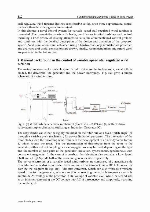
The main components of a variable speed wind turbine are the turbine rotor, usually three
bladed, the drivetrain, the generator and the power electronics. Fig. 1(a) gives a simple
schematic of a wind turbine.
Fig. 1. (a) Wind turbine schematic mechanical (Biachi et al., 2007) and (b) with electrical subsystem simple schematics, (utilizing an Induction Generator-IG).
The rotor blades can either be rigidly mounted on the rotor hub at a fixed “pitch angle” or
through a variable pitch mechanism, for power limitation purposes. The interaction of the
rotor blades with the oncoming wind results in the development of an aerodynamic torque
Ta which rotates the rotor. For the transmission of this torque from the rotor to the
generator, either a direct coupling or a step-up gearbox may be used, depending on the type
and the number of pole pairs of the generator (induction, synchronous, synchronous with
permanent magnets). In the case of a gearbox, the drivetrain also contains a Low Speed
Shaft and a High Speed Shaft, at the rotor and generator side respectively.
The power electronics of a variable speed wind turbine are comprised of a generator-side
converter and a grid-side converter, both connected back-to-back via a DC link, as can be
seen by the diagram in Fig. 1(b). The first converter, which can also work as a variable
speed drive for the generator, acts as a rectifier, converting the variable frequency/variable
amplitude AC voltage of the generator to DC voltage of variable level, while the second acts
as an inverter, converting the DC voltage into AC of a frequency and amplitude, matching
that of the grid.
www.intechopen.com
A Complete Control Scheme for Variable Speed Stall Regulated Wind Turbines 311
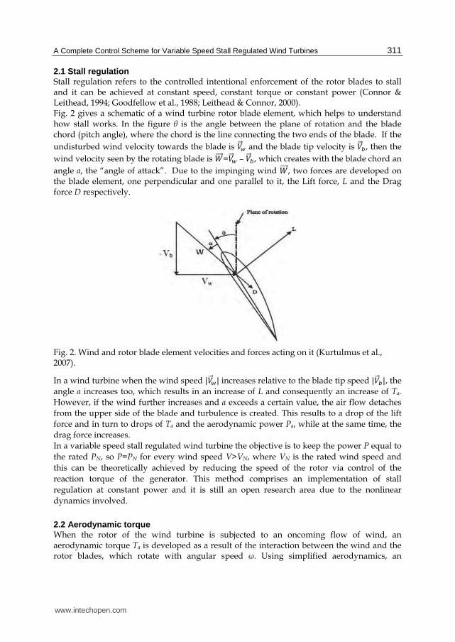
2.1 Stall regulation Stall regulation refers to the controlled intentional enforcement of the rotor blades to stall and it can be achieved at constant speed, constant torque or constant power (Connor & Leithead, 1994; Goodfellow et al., 1988; Leithead & Connor, 2000). Fig. 2 gives a schematic of a wind turbine rotor blade element, which helps to understand how stall works. In the figure θ is the angle between the plane of rotation and the blade chord (pitch angle), where the chord is the line connecting the two ends of the blade. If the
undisturbed wind velocity towards the blade is 撃屎王栂 and the blade tip velocity is 撃屎王長, then the
wind velocity seen by the rotating blade is 激屎屎屎王=撃屎王栂 – 撃屎王長, which creates with the blade chord an
angle a, the “angle of attack”. Due to the impinging wind 激屎屎屎王, two forces are developed on the blade element, one perpendicular and one parallel to it, the Lift force, L and the Drag force D respectively.
Fig. 2. Wind and rotor blade element velocities and forces acting on it (Kurtulmus et al., 2007).
In a wind turbine when the wind speed |撃屎王栂| increases relative to the blade tip speed |撃屎王長|, the
angle α increases too, which results in an increase of L and consequently an increase of Ta.
However, if the wind further increases and α exceeds a certain value, the air flow detaches
from the upper side of the blade and turbulence is created. This results to a drop of the lift
force and in turn to drops of Ta and the aerodynamic power Pa, while at the same time, the
drag force increases.
In a variable speed stall regulated wind turbine the objective is to keep the power P equal to
the rated PN, so P=PN for every wind speed V>VN, where VN is the rated wind speed and
this can be theoretically achieved by reducing the speed of the rotor via control of the
reaction torque of the generator. This method comprises an implementation of stall
regulation at constant power and it is still an open research area due to the nonlinear
dynamics involved.
2.2 Aerodynamic torque When the rotor of the wind turbine is subjected to an oncoming flow of wind, an aerodynamic torque Ta is developed as a result of the interaction between the wind and the rotor blades, which rotate with angular speed ω. Using simplified aerodynamics, an
www.intechopen.com
Fundamental and Advanced Topics in Wind Power 312
expression of the aerodynamic power Pa has been derived (Biachi et al., 2007; Manwell, 2002). This is given in Eqn. 1:
鶏銚 噺 怠態 講貢迎態系椎撃戴 (1)
where ρ is the air density, R the radius of the rotor, Cp is the power coefficient of the rotor and V the effective wind speed seen by the rotor, which is a result of a number of phenomena due to the interaction of the rotor and the oncoming wind (Biachi et al., 2007). In particular, V is a quantity used in the equations that attempts to represent the effect on the produced torque of a 2-dimensional wind field with a 1-dimensional quantity. That way, harmonic components of the aerodynamic torque caused by the rotational sampling of the rotor (due to the wind shear or the small spatial correlation of the wind turbulence as well as to the tower shadow) are assumed to be present in the V timeseries. From the above it is obvious that V is a non-measurable quantity, since an anemometer gives only a point wind speed far from the turbine rotor (Leithead & Connor, 2000). Cp is defined as ratio of the power extracted from the wind to the power available in the wind (Manwell, 2002; Parker, 2000) and it is a measure of the aerodynamic efficiency of the rotor, which indicates the ability of the rotor to extract power from the wind. It is also a nonlinear function of the tip-speed ratio 膏 噺 降迎/撃 and the pitch angle θ and it is particular for each rotor, with its shape depending on the rotor blade profile. Cp has a theoretical maximum of 系椎尿尼猫=0.593, known as the Betz limit, which indicates that the maximum ability to extract
power from the wind is less than 60% (Biachi et al., 2007; Parker, 2000). In practice this value is lower, usually 系椎尿尼猫=0.45. In general, for a wind turbine it is desirable to operate at 系椎尿尼猫 for
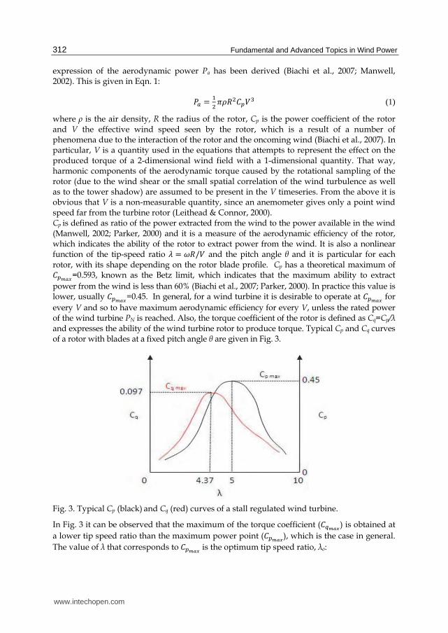
every V and so to have maximum aerodynamic efficiency for every V, unless the rated power of the wind turbine PN is reached. Also, the torque coefficient of the rotor is defined as Cq=Cp/λ and expresses the ability of the wind turbine rotor to produce torque. Typical Cp and Cq curves of a rotor with blades at a fixed pitch angle θ are given in Fig. 3.
Fig. 3. Typical Cp (black) and Cq (red) curves of a stall regulated wind turbine.
In Fig. 3 it can be observed that the maximum of the torque coefficient (系槌尿尼猫) is obtained at
a lower tip speed ratio than the maximum power point (系椎尿尼猫), which is the case in general.
The value of λ that corresponds to 系椎尿尼猫 is the optimum tip speed ratio, λο:
www.intechopen.com
A Complete Control Scheme for Variable Speed Stall Regulated Wind Turbines 313
膏艇 噺 降艇迎撃 (2)
where ωο is the optimum rotational speed of the rotor for a given V.
The aerodynamic torque of the rotor of the wind turbine is given by:
劇銚 噺 鶏銚降 噺 なに降 講貢迎態系椎撃戴 噺 なに 講貢迎戴系槌撃態 (3)
The above expression for the aerodynamic torque has been used for the control system
design and for wind turbine simulations using a hardware-in-loop simulator as will be seen
later. In particular, for the wind turbine simulation, a model of the dynamic inflow has also
been included, using a lead lag filter (Parker, 2000). The dynamic inflow relates to dynamic
phenomena occurring during the development of 劇銚 under changes of ω or V, which are not
represented in Eqn. 3 (Biachi et al., 2007; Parker, 2000).
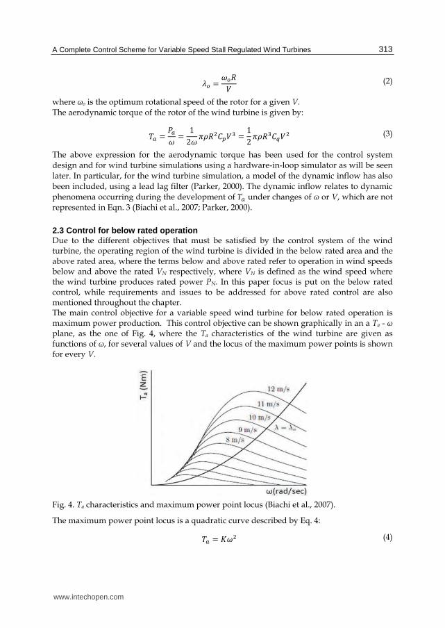
2.3 Control for below rated operation Due to the different objectives that must be satisfied by the control system of the wind turbine, the operating region of the wind turbine is divided in the below rated area and the above rated area, where the terms below and above rated refer to operation in wind speeds below and above the rated VN respectively, where VN is defined as the wind speed where the wind turbine produces rated power PN. In this paper focus is put on the below rated control, while requirements and issues to be addressed for above rated control are also mentioned throughout the chapter. The main control objective for a variable speed wind turbine for below rated operation is maximum power production. This control objective can be shown graphically in an a Ta - ω plane, as the one of Fig. 4, where the Ta characteristics of the wind turbine are given as functions of ω, for several values of V and the locus of the maximum power points is shown for every V.
Fig. 4. Ta characteristics and maximum power point locus (Biachi et al., 2007).
The maximum power point locus is a quadratic curve described by Eq. 4: 劇銚 噺 計降態 (4)
www.intechopen.com
Fundamental and Advanced Topics in Wind Power 314
where
計 噺 なに膏艇戴 貢講迎泰系椎尿尼猫 (5)
The control of the generator of commercial variable speed pitch regulated wind turbines in below rated conditions is currently performed by setting its torque equal to the value given in Eqn. 4 (Biachi et al., 2007; Manwell, 2002; Leithead, 1990; Bossanyi, 2003). Hence, the control law for the generator torque is given as: 劇直 噺 計降態 (6)
Compensation for the drivetrain losses can be also included: 劇直 噺 計降態 伐 紘降 (7)
where γ is the estimated friction loss coefficient and K is given by Eqn. 5. It is mentioned that in general, measurement of the rotor speed ω is not available, therefore, the control of Eqns. 6-7 is realized through the generator speed measurement ωg, which is nominally equal to ω scaled up with the gearbox ratio, N, in case this is used. Of course, the factor K of Eqn. 5 then takes into consideration the presence of a gearbox. The control of Eqns. 6-7 is often mentioned as Indirect control, since it does not take into account the dynamics of the wind turbine, due to the large rotor inertia and therefore it has the disadvantage that it can lead to considerable deviations of the operating point from 系椎尿尼猫, during fast wind speed changes (Biachi et al., 2007; Leithead, 1990). It is established in
(Leithead, 1990) that this control law performs better, when the Cp curve is broad, as is the case in variable speed pitch regulated wind turbines, so excursions of the operating point do not cause considerable power loss. Similar conclusions can also be found in (Bossanyi, 2003). However, this control method is not suitable for variable speed stall regulated wind turbines due to the different requirements in the shape of the Cp curve. Specifically, in (Mercer & Bossanyi, 1996) it has been established that by using a rotor with a narrower Cp
curve, less rotor speed reduction is required to achieve stall regulation at constant power. That way less control action is required and more effective power regulation is achieved. Due to the requirement of a narrow Cp curve for a variable speed stall regulated wind turbine, excursions of the operating point from the 系椎尿尼猫 can cause considerable reduction of
the produced power, when the conventional control of Eqns. 6-7 is applied. In the literature techniques based on closed loop control of the generator (Direct control) have also been proposed, as a way to overcome the shortcomings of the conventional control. In particular, the most notable are (Østergaard et al., 2007), where the option to estimate V using a Kalman filter as a torque observer and a Newton-Raphson method to solve Eqn. 3 is mentioned and (Biachi et al., 2007) where the use of speed control for the generator is proposed, based on the knowledge of V and using a Linear Parameter Varying controller. Furthermore, (Boukhezzar & Siguerdidjane, 2005) proposes a combination of the aforementioned wind estimation method with a nonlinear controller (dynamic state feedback linearization) to control the speed of the generator. A shortcoming of the above techniques is that there are certain challenges regarding the use of a Kalman filter for Ta estimation, since this has to be tuned appropriately (Bourlis & Bleijs, 2010a, 2010b). Also, challenges regarding the applicability of the V estimation algorithm in variable speed stall regulated wind turbines are not addressed. Furthermore, the
www.intechopen.com
A Complete Control Scheme for Variable Speed Stall Regulated Wind Turbines 315
implementation of a Linear Parameter Varying controller in an actual system is quite an involved task, while the proposed nonlinear controller requires online calculation of derivatives, so it is impractical and also does not have guaranteed robustness. To overcome the above challenges, (Bourlis & Bleijs, 2010a, 2010b) propose the use of adaptive Kalman filtering, which does not require tuning and therefore is more trustable. In addition, the use of a single Proportional-Integral (PI) speed controller is proposed, which is shown to be quite effective through hardware simulation results. In this chapter a control system using adaptive Kalman filtering and Newton-Raphson method is proposed, similar to (Bourlis & Bleijs, 2010a), but now a gain-scheduled PI controller is used. This controller can have improved characteristics for operation at high wind speeds as it will be seen. The following sections present the design process of the control system including the features and the importance of each part of the control system, hardware simulation results and finally conclusions and recommendations for future work.
3. Control strategy of a variable speed stall regulated wind turbine
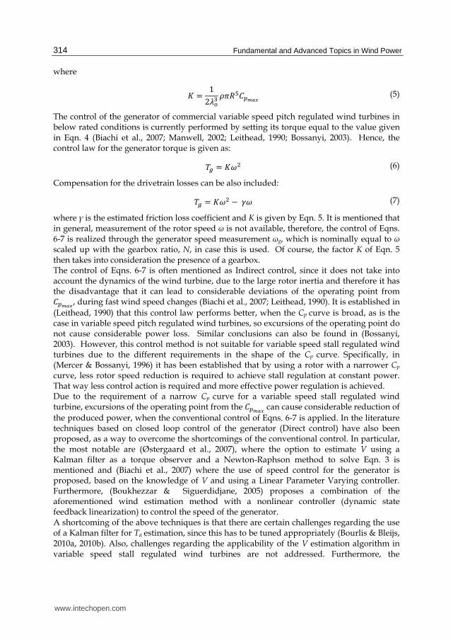
The control system of a variable speed stall regulation wind turbines should mainly satisfy the following two objectives: 1. Maximum power production for below rated wind speeds. 2. Power limitation for above rated wind speeds. How the above two goals can be achieved, is shown in Fig. 5, where the optimum locus of the operating point for a variable speed stall regulated wind turbine over the whole operating region is shown in a Ta-ω plane (Biachi et al., 2007) and where ωΑ is the rotor rotational speed that the control starts operating, ωN the rated rotational speed, VN the rated wind speed, PN the rated power and TN the rated torque of the wind turbine.
Fig. 5. Control strategy of a variable speed stall regulated wind turbine (Biachi et al., 2007).
Part AB is the maximum power locus and part BC represents constant speed operation, after the wind turbine reaches its rotational speed limit at point B. After this, when the power reaches its rated value at the point C, the operating point should move on the curve CD, which is part of the hyperbolic curve of constant power 鶏朝 噺 降劇銚. The system stops operating when it reaches the cut-out wind speed at point D. At this point the torque reaches the value TN, which in fact can be 1.5*TNgen, where TNgen is the rated torque of the generator.
www.intechopen.com
Fundamental and Advanced Topics in Wind Power 316
Other issues to be addressed by a control system apart from stabilizing the nonlinear system in the whole operating region, is to effectively suppress drivetrain oscillations, especially due to the first drivetrain mode, which is associated with the rotor blade resonance frequency. Such oscillations can be excited by high frequency components in V and therefore active damping should be provided by the controller.
4. Proposed control system
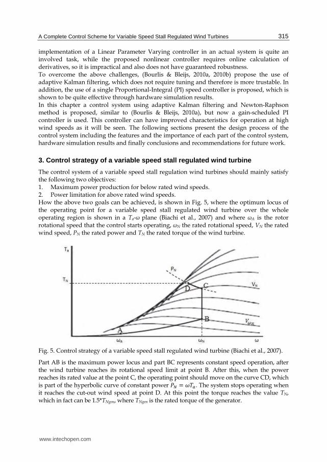
Fig. 6 gives an overview of the proposed control system.
Fig. 6. Overview of the proposed control system.
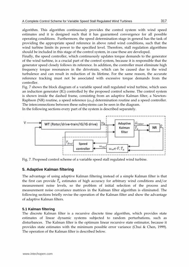
As can be seen, the control system receives only a measurement of the generator speed and outputs the generator torque demand. The generator drive can always provide a speed measurement and is also responsible for driving the generator with the demanded torque. The control system is divided in three subsequent stages, an aerodynamic torque estimation stage, a speed reference determination stage and a speed controller. The aerodynamic torque estimation stage has been implemented using adaptive Kalman filters (Bourlis & Bleijs, 2010a, 2010b), which can provide torque estimates of highest possible accuracy. The high accuracy of the torque estimates is very important, because it results in more efficient operation for the wind turbine. The speed reference determination stage is of high importance, because it provides the optimum speed reference for the wind turbine for below rated operation, based on the wind speed conditions, in order to achieve maximum energy extraction. For this reason this stage includes a wind speed estimation process, using a high performance Newton-Raphson
www.intechopen.com
A Complete Control Scheme for Variable Speed Stall Regulated Wind Turbines 317
algorithm. This algorithm continuously provides the control system with wind speed estimates and it is designed such that it has guaranteed convergence for all possible operating conditions. Furthermore, the speed determination stage in general has the task of providing the appropriate speed reference in above rated wind conditions, such that the wind turbine limits its power to the specified level. Therefore, stall regulation algorithms should be included in this stage of the control system, in case these are developed. Finally, the speed controller, which continuously updates torque demands to the generator of the wind turbine, is a crucial part of the control system, because it is responsible that the generator speed closely follows its reference. In addition, the controller must eliminate high frequency torque resonances in the drivetrain, which can be caused due to the wind turbulence and can result in reduction of its lifetime. For the same reason, the accurate reference tracking must not be associated with excessive torque demands from the controller. Fig. 7 shows the block diagram of a variable speed stall regulated wind turbine, which uses an induction generator (IG) controlled by the proposed control scheme. The control system is shown inside the dashed frame, consisting from an adaptive Kalman filter, a Newton-Raphson (NR) routine, a speed reference (ωref) determination routine and a speed controller. The interconnections between these subsystems can be seen in the diagram. In the following sections every part of the system is described separately.
Fig. 7. Proposed control scheme of a variable speed stall regulated wind turbine.
5. Adaptive Kalman filtering
The advantage of using adaptive Kalman filtering instead of a simple Kalman filter is that
the first can provide 劇侮銚 estimates of high accuracy for arbitrary wind conditions and/or
measurement noise levels, so the problem of initial selection of the process and
measurement noise covariance matrices in the Kalman filter algorithm is eliminated. The
following sections briefly revise the operation of the Kalman filter and show the advantage
of adaptive Kalman filters.
5.1 Kalman filtering The discrete Kalman filter is a recursive discrete time algorithm, which provides state
estimates of linear dynamic systems subjected to random perturbations, such as
disturbances. The Kalman filter is the optimum linear recursive state estimator, because it
provides state estimates with the minimum possible error variance (Chui & Chen, 1999).
The operation of the Kalman filter is described below.
www.intechopen.com
Fundamental and Advanced Topics in Wind Power 318
Eqns. 8-9 comprise a discrete time dynamic system: 捲賃袋怠 噺 溝捲賃 髪 康憲賃 髪 拳賃 (8)
権賃袋怠 噺 茎捲賃袋怠 髪 券賃袋怠 (9)
where k=t/Ts, with t the continuous time scale and Ts(sec) the sampling time of the system. In Eqns. 8-9 捲є迎津 is the state vector, 憲є迎陳 the input vector, 権є迎追 is the measurement vector, 拳є迎津 a white noise sequence, which models a fictitious process noise reflecting the modeling uncertainties in Eqn. 8 and 券є迎追 is the measurement noise, a white noise sequence representing the noise due to the sensor and quantization of the data acquisition system. These noise sequences are assumed to be independent of each other, which is reasonably valid for a wind turbine and have normal probability distributions (Anderson & Moore, 1979): 喧岫拳岻~ 軽岫ど, 芸岻 (10)
喧岫券岻~ 軽岫ど, 迎岻 (11)
where Qє迎津青津 and Rє迎追青追 are unknown and possibly changeable over time. The Kalman filter receives as inputs the vector u of the dynamic system and the noisy measurement vector z of some of its states and produces an estimate for all of the states of Eqn. 8. The algorithm is structured in a prediction & update scheme according to the following equations: Predict: 捲賦賃袋怠|賃 噺 溝 捲賦賃|賃 髪 康憲賃 (12)
where 捲賦賃袋怠|賃 ,鶏侮賃袋怠|賃 and 捲賦賃袋怠|賃袋怠, 鶏侮賃袋怠|賃袋怠 are the a-priori and a-posteriori state vector
and state estimation error covariance respectively, while 計賃袋怠 is the Kalman gain, which is
updated in every cycle.
During the operation of the algorithm, the Kalman gain soon converges to a steady state
value, which can therefore be calculated offline (Chui & Chen, 1999). However, when the
Kalman filter is enhanced with adaptive routines, online adjustment of 計賃袋怠 is performed. At the prediction step, the estimated value捲賦賃|賃, which is the mean of the true state vector at
time k, is dynamically projected forward at time k+1 to produce捲賦賃袋怠|賃.
At the update step, the mean 捲賦賃袋怠|賃 is corrected subject to the measurement 権賃袋怠 to give the
a-posteriori mean捲賦賃袋怠|賃袋怠.
www.intechopen.com
A Complete Control Scheme for Variable Speed Stall Regulated Wind Turbines 319
The same mechanism holds for the propagation of the covariance 鶏撫 of the true state 捲 around its mean 捲賦.
As can be seen from Eqns. 12-16 the Kalman filter in principle contains a copy of the applied
dynamic system, the state vector of which, 捲賦賃 is corrected at every update step by the
correcting term 計賃袋怠岫権賃袋怠 伐 抗捲賦賃袋怠|賃岻 of Eqn. 14. The expression inside the parenthesis is
called the Innovation sequence of the Kalman filter: 堅賃 噺 権賃袋怠 伐 抗 捲賦賃袋怠|賃 (17)
which is equal to the estimation error at every time step. When the Kalman filter state estimate is optimum, 堅賃 is a white noise sequence (Chui & Chen, 1999). The operation of any Q and R adaptation algorithms that are included in the Kalman filter is based on the statistics of the innovation sequence (Bourlis & Bleijs, 2010a, 2010b). Regarding the stability of the Kalman filter algorithm, this is always guaranteed providing
that the dynamic system of Eqns. 8-9 is stable and that Q and R have been selected
appropriately. In the case of the wind turbine, the dynamic system is always stable, since in
Eqns. 8-9 only the dynamics of the drivetrain are included, which have to be stable by
default. In addition, the Q and R are continuously updated appropriately by adaptive
algorithms and the stability of the adaptive Kalman filter can be easily assessed through
software or hardware simulations.
From the above it becomes obvious that the stability of the closed loop control system of
Figs. 6-7 is then guaranteed provided that the speed controller stabilizes the system.
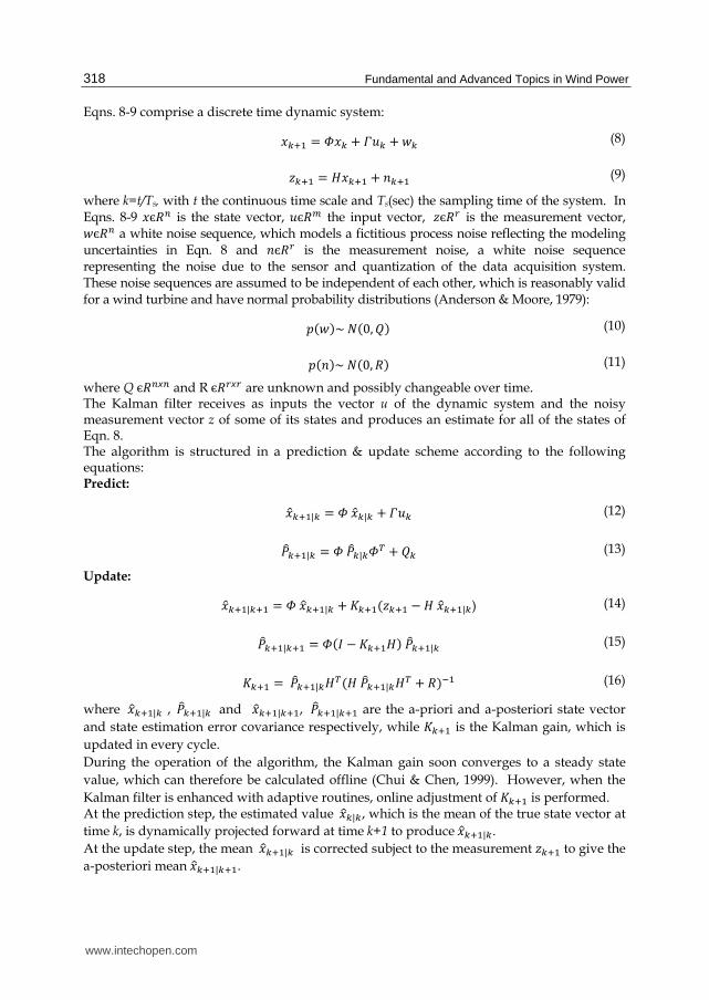
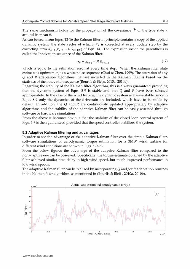
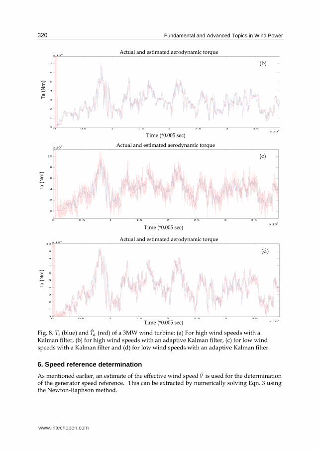
5.2 Adaptive Kalman filtering and advantages In order to see the advantage of the adaptive Kalman filter over the simple Kalman filter,
software simulations of aerodynamic torque estimation for a 3MW wind turbine for
different wind conditions are shown in Figs. 8 (a-b).
From the below figures the advantage of the adaptive Kalman filter compared to the
nonadaptive one can be observed. Specifically, the torque estimate obtained by the adaptive
filter achieved similar time delay in high wind speed, but much improved performance in
low wind speeds.
The adaptive Kalman filter can be realized by incorporating Q and/or R adaptation routines
in the Kalman filter algorithm, as mentioned in (Bourlis & Bleijs, 2010a, 2010b).
0 0.5 1 1.5 2 2.5 3 3.5
x 104
0
1
2
3
4
5
6
7
x 106
Time (*0.005 sec)
Ta (N
m)
Actual and estimated Ta
(a)
Actual and estimated aerodynamic torque
www.intechopen.com
Fundamental and Advanced Topics in Wind Power 320
Fig. 8. Ta (blue) and 劇侮銚 (red) of a 3MW wind turbine: (a) For high wind speeds with a Kalman filter, (b) for high wind speeds with an adaptive Kalman filter, (c) for low wind speeds with a Kalman filter and (d) for low wind speeds with an adaptive Kalman filter.
6. Speed reference determination
As mentioned earlier, an estimate of the effective wind speed 撃侮 is used for the determination of the generator speed reference. This can be extracted by numerically solving Eqn. 3 using the Newton-Raphson method.
0 0.5 1 1.5 2 2.5 3 3.5
x 104
0
1
2
3
4
5
6
7
x 106
Time (*0.005 sec)
Ta (Nm)
Actual and estimated Ta
0 0.5 1 1.5 2 2.5 3 3.5
x 104
0
2
4
6
8
10
x 105
Time (*0.005 sec)
Ta (N
m)
Actual and estimated Ta
0 0.5 1 1.5 2 2.5 3 3.5
x 104
0
1
2
3
4
5
6
7
8
9
10x 10
5
Time (*0.005 sec)
Ta (Nm)
Actual and estimated Ta
(b)
(d)
(c)
Time (*0.005 sec)
Time (*0.005 sec)
Actual and estimated aerodynamic torque
Actual and estimated aerodynamic torque
Actual and estimated aerodynamic torque
Time (*0.005 sec)
www.intechopen.com
A Complete Control Scheme for Variable Speed Stall Regulated Wind Turbines 321
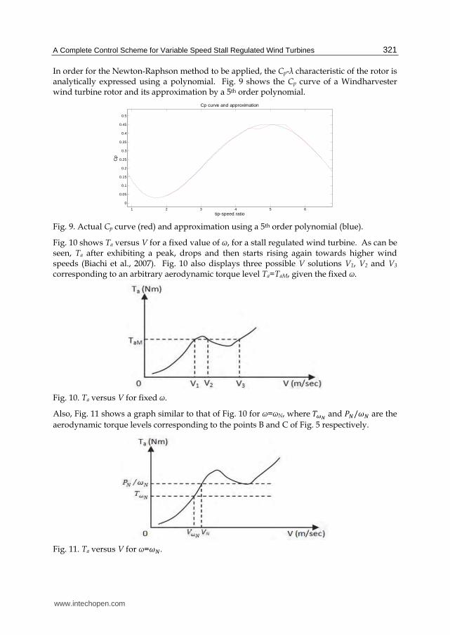
In order for the Newton-Raphson method to be applied, the Cp-λ characteristic of the rotor is analytically expressed using a polynomial. Fig. 9 shows the Cp curve of a Windharvester wind turbine rotor and its approximation by a 5th order polynomial.
Fig. 9. Actual Cp curve (red) and approximation using a 5th order polynomial (blue).
Fig. 10 shows Ta versus V for a fixed value of ω, for a stall regulated wind turbine. As can be seen, Ta after exhibiting a peak, drops and then starts rising again towards higher wind speeds (Biachi et al., 2007). Fig. 10 also displays three possible V solutions V1, V2 and V3
corresponding to an arbitrary aerodynamic torque level Ta=TaM, given the fixed ω.
Fig. 10. Ta versus V for fixed ω.
Also, Fig. 11 shows a graph similar to that of Fig. 10 for ω=ωN, where 劇摘灘 and 鶏朝/降朝 are the
aerodynamic torque levels corresponding to the points B and C of Fig. 5 respectively.
Fig. 11. Ta versus V for ω=降朝.
1 2 3 4 5 6
0
0.05
0.1
0.15
0.2
0.25
0.3
0.35
0.4
0.45
0.5
tip-speed ratio
Cp
Cp curve and approximation
www.intechopen.com
Fundamental and Advanced Topics in Wind Power 322
For the part AB of Fig. 5, the optimum speed reference is: 降追勅捗 噺 碇轍蝶迭眺 , where V1 is the lowest
V solution seen in Fig. 10. Also, for the part BC the speed reference is: 降追勅捗 噺 降朝. In addition, from Fig. 11 it can be seen that for ω=降朝 when V1>撃摘灘, the aerodynamic torque is always Ta>劇摘灘, so there is a monotonic relation between V1 and Ta. Therefore, V1 can be effectively used in order to switch between the parts AB and BC. So, 降追勅捗 for the part ABC can be expressed as:
降追勅捗 噺 崔膏待撃怠迎 , 撃怠 隼 撃摘灘降朝 , 撃怠 伴 撃摘灘 , (18)
Regarding V1, it can be easily obtained with a Newton-Raphson if this is initialized at an appropriate point, as seen in Fig. 12, where the expression 劇銚謎 伐 劇銚 versus V is shown.
Fig. 12. Newton-Raphson routine NR1 used for V solution extraction of Eqn. 3.
Fig. 13 shows the actual V and its estimate, 撃侮 obtained in Simulink using the Newton-Raphson routine for the model of the aforementioned Windharvester wind turbine.
Fig. 13. Actual V (blue) and estimated 撃侮 (red) using NR1.
As can be seen, the wind speed estimation is very accurate. In the next section, the speed control design is described.
7. Gain scheduled proportional-integral speed controller
The speed controller should satisfy conflicting requirements, such as accurate speed reference tracking and effective disturbance rejection due to high frequency components of
0.5 1 1.5 2 2.5 3 3.5
x 104
3
4
5
6
7
8
9
Time (*0.005 sec)
V (m/sec
)
Actual and estimated V without dynamic inflow effects simulatedActual and estimated effective wind speed
www.intechopen.com
A Complete Control Scheme for Variable Speed Stall Regulated Wind Turbines 323
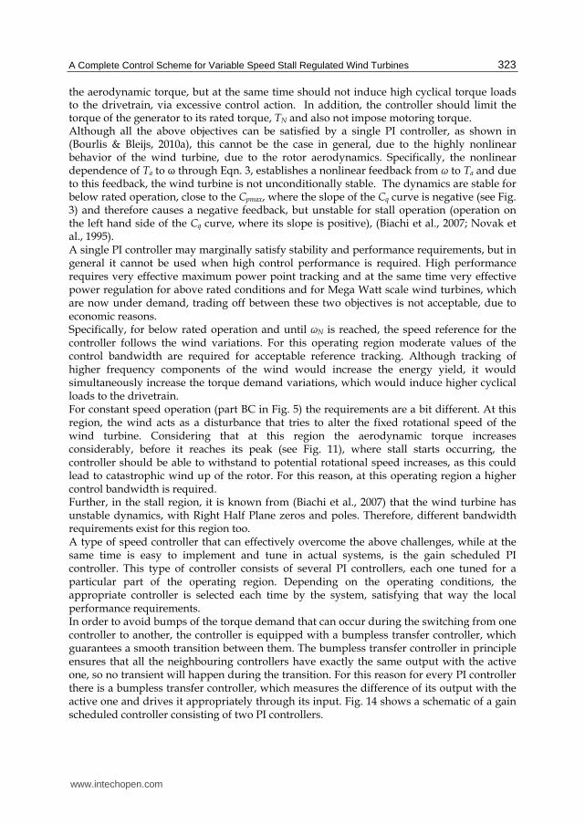
the aerodynamic torque, but at the same time should not induce high cyclical torque loads to the drivetrain, via excessive control action. In addition, the controller should limit the torque of the generator to its rated torque, TN and also not impose motoring torque. Although all the above objectives can be satisfied by a single PI controller, as shown in (Bourlis & Bleijs, 2010a), this cannot be the case in general, due to the highly nonlinear behavior of the wind turbine, due to the rotor aerodynamics. Specifically, the nonlinear dependence of Ta to ω through Eqn. 3, establishes a nonlinear feedback from ω to Ta and due to this feedback, the wind turbine is not unconditionally stable. The dynamics are stable for below rated operation, close to the Cpmax, where the slope of the Cq curve is negative (see Fig. 3) and therefore causes a negative feedback, but unstable for stall operation (operation on the left hand side of the Cq curve, where its slope is positive), (Biachi et al., 2007; Novak et al., 1995). A single PI controller may marginally satisfy stability and performance requirements, but in general it cannot be used when high control performance is required. High performance requires very effective maximum power point tracking and at the same time very effective power regulation for above rated conditions and for Mega Watt scale wind turbines, which are now under demand, trading off between these two objectives is not acceptable, due to economic reasons. Specifically, for below rated operation and until ωΝ is reached, the speed reference for the controller follows the wind variations. For this operating region moderate values of the control bandwidth are required for acceptable reference tracking. Although tracking of higher frequency components of the wind would increase the energy yield, it would simultaneously increase the torque demand variations, which would induce higher cyclical loads to the drivetrain. For constant speed operation (part BC in Fig. 5) the requirements are a bit different. At this region, the wind acts as a disturbance that tries to alter the fixed rotational speed of the wind turbine. Considering that at this region the aerodynamic torque increases considerably, before it reaches its peak (see Fig. 11), where stall starts occurring, the controller should be able to withstand to potential rotational speed increases, as this could lead to catastrophic wind up of the rotor. For this reason, at this operating region a higher control bandwidth is required. Further, in the stall region, it is known from (Biachi et al., 2007) that the wind turbine has unstable dynamics, with Right Half Plane zeros and poles. Therefore, different bandwidth requirements exist for this region too. A type of speed controller that can effectively overcome the above challenges, while at the same time is easy to implement and tune in actual systems, is the gain scheduled PI controller. This type of controller consists of several PI controllers, each one tuned for a particular part of the operating region. Depending on the operating conditions, the appropriate controller is selected each time by the system, satisfying that way the local performance requirements. In order to avoid bumps of the torque demand that can occur during the switching from one controller to another, the controller is equipped with a bumpless transfer controller, which guarantees a smooth transition between them. The bumpless transfer controller in principle ensures that all the neighbouring controllers have exactly the same output with the active one, so no transient will happen during the transition. For this reason for every PI controller there is a bumpless transfer controller, which measures the difference of its output with the active one and drives it appropriately through its input. Fig. 14 shows a schematic of a gain scheduled controller consisting of two PI controllers.
www.intechopen.com
Fundamental and Advanced Topics in Wind Power 324
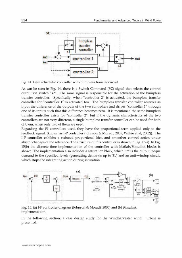
Fig. 14. Gain scheduled controller with bumpless transfer circuit.
As can be seen in Fig. 14, there is a Switch Command (SC) signal that selects the control
output via switch “s2”. The same signal is responsible for the activation of the bumpless
transfer controller. Specifically, when “controller 2” is activated, the bumpless transfer
controller for “controller 1” is activated too. The bumpless transfer controller receives as
input the difference of the outputs of the two controllers and drives “controller 1” through
one of its inputs such that this difference becomes zero. It is mentioned the same bumpless
transfer controller exists for “controller 2”, but if the dynamic characteristics of the two
controllers are not very different, a single bumpless transfer controller can be used for both
of them, when only two of them are used.
Regarding the PI controllers used, they have the proportional term applied only to the
feedback signal, (known as I-P controller (Johnson & Moradi, 2005; Wilkie et al, 2002)). The
I-P controller exhibits a reduced proportional kick and smoother control action under
abrupt changes of the reference. The structure of this controller is shown in Fig. 15(a). In Fig.
15(b) the discrete time implementation of the controller with Matlab/Simulink blocks is
shown. The implementation also includes a saturation block, which limits the output torque
demand to the specified levels (generating demands up to TN) and an anti-windup circuit,
which stops the integrating action during saturation.
In the following section, a case design study for the Windharvester wind turbine is presented.
(a) (b)
www.intechopen.com
A Complete Control Scheme for Variable Speed Stall Regulated Wind Turbines 325
8. Case design study
The analysis that follows is based on data from a 25kW Windharvester constant speed stall regulated wind turbine that has been installed at the Rutherford Appleton Laboratory in Oxfordshire of England. The control system that has been described in the previous sections has been designed for this wind turbine and the complete system has been simulated in a hardware-in-loop wind turbine simulator.
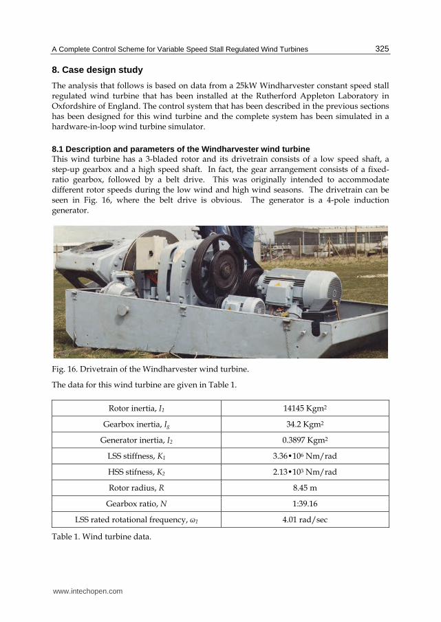
8.1 Description and parameters of the Windharvester wind turbine This wind turbine has a 3-bladed rotor and its drivetrain consists of a low speed shaft, a step-up gearbox and a high speed shaft. In fact, the gear arrangement consists of a fixed-ratio gearbox, followed by a belt drive. This was originally intended to accommodate different rotor speeds during the low wind and high wind seasons. The drivetrain can be seen in Fig. 16, where the belt drive is obvious. The generator is a 4-pole induction generator.
Fig. 16. Drivetrain of the Windharvester wind turbine.
The data for this wind turbine are given in Table 1.
Rotor inertia, I1 14145 Kgm2
Gearbox inertia, Ig 34.2 Kgm2
Generator inertia, I2 0.3897 Kgm2
LSS stiffness, K1 3.36�106 Nm/rad
HSS stifness, K2 2.13�103 Nm/rad
Rotor radius, R 8.45 m
Gearbox ratio, N 1:39.16
LSS rated rotational frequency, ω1 4.01 rad/sec
Table 1. Wind turbine data.
www.intechopen.com
Fundamental and Advanced Topics in Wind Power 326
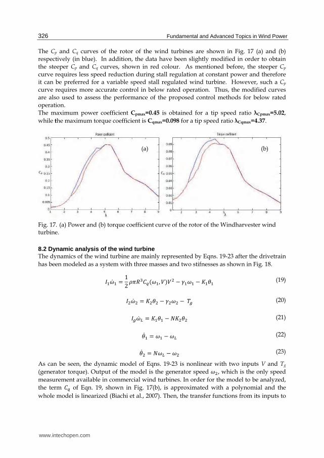
The Cp and Cq curves of the rotor of the wind turbines are shown in Fig. 17 (a) and (b)
respectively (in blue). In addition, the data have been slightly modified in order to obtain
the steeper Cp and Cq curves, shown in red colour. As mentioned before, the steeper Cp
curve requires less speed reduction during stall regulation at constant power and therefore
it can be preferred for a variable speed stall regulated wind turbine. However, such a Cp
curve requires more accurate control in below rated operation. Thus, the modified curves
are also used to assess the performance of the proposed control methods for below rated
operation.
The maximum power coefficient Cpmax=0.45 is obtained for a tip speed ratio λCpmax=5.02,
while the maximum torque coefficient is Cqmax=0.098 for a tip speed ratio λCqmax=4.37.
Fig. 17. (a) Power and (b) torque coefficient curve of the rotor of the Windharvester wind turbine.
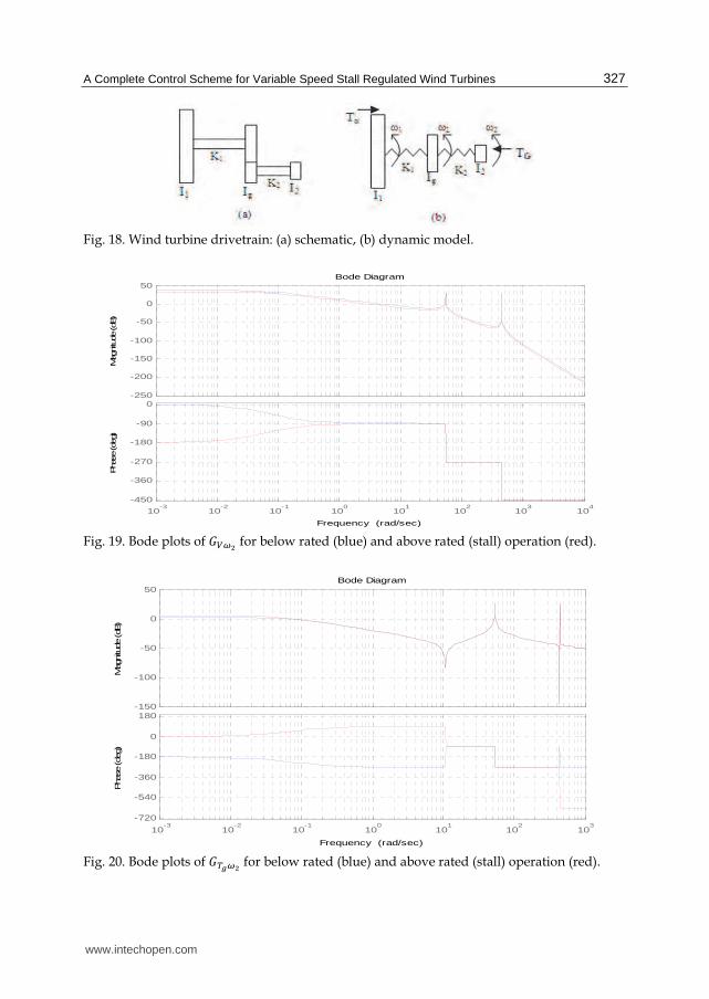
8.2 Dynamic analysis of the wind turbine
The dynamics of the wind turbine are mainly represented by Eqns. 19-23 after the drivetrain
has been modeled as a system with three masses and two stifnesses as shown in Fig. 18.
荊怠降岌 怠 噺 なに 貢講迎戴系槌岫降怠, 撃岻撃態 伐 紘怠降怠 伐 攻怠肯怠 (19)
荊態降岌 態 噺 攻態肯態 伐 紘態降態 伐 劇直 (20)
荊直降岌 挑 噺 攻怠肯怠 伐 軽攻態肯態 (21)
肯岌怠 噺 降怠 伐 降挑 (22)
肯岌態 噺 軽降挑 伐 降態 (23)
As can be seen, the dynamic model of Eqns. 19-23 is nonlinear with two inputs V and Tg
(generator torque). Output of the model is the generator speed 降態, which is the only speed
measurement available in commercial wind turbines. In order for the model to be analyzed,
the term 系槌 of Eqn. 19, shown in Fig. 17(b), is approximated with a polynomial and the
whole model is linearized (Biachi et al., 2007). Then, the transfer functions from its inputs to
(a) (b)
www.intechopen.com
A Complete Control Scheme for Variable Speed Stall Regulated Wind Turbines 327
Fig. 19. Bode plots of 罫蝶摘鉄 for below rated (blue) and above rated (stall) operation (red).
Fig. 20. Bode plots of 罫脹虹摘鉄 for below rated (blue) and above rated (stall) operation (red).
-250
-200
-150
-100
-50
0
50
Mag
nitude
(dB
)
10-3
10-2
10-1
100
101
102
103
104
-450
-360
-270
-180
-90
0
Pha
se (de
g)
Bode Diagram
Frequency (rad/sec)
-150
-100
-50
0
50
Mag
nitu
de (dB
)
10-3
10-2
10-1
100
101
102
103
-720
-540
-360
-180
0
180
Pha
se (de
g)
Bode Diagram
Frequency (rad/sec)
www.intechopen.com
Fundamental and Advanced Topics in Wind Power 328
its output, 罫蝶摘鉄and 罫脹虹摘鉄are examined for different operating conditions. The Bode plots of 罫蝶摘鉄 and 罫脹虹摘鉄 are shown in Figs. 19 and 20 respectively, for two operating points, namely
one for below rated operation (ω1,V)=(4rad/sec, 6.76m/sec) and one for above rated
operation, (4 rad/sec, 8.76m/sec).
As can be seen from the above plots, a phase change of 180° occurs, for frequencies less than
0.1rad/sec as the operating point of the wind turbine moves from below rated to stall
operation, for both transfer functions. In addition, the first drivetrain mode can be observed
at 53rad/sec.
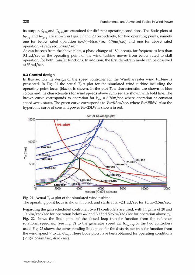
8.3 Control design
In this section the design of the speed controller for the Windharvester wind turbine is
presented. In Fig. 21 the actual Ta-ω plot for the simulated wind turbine including the
operating point locus (black), is shown. In the plot Ta-ω characteristics are shown in blue
colour and the characteristics for wind speeds above 20m/sec are shown with bold line. The
brown curve corresponds to operation for 撃摘灘 噺 は.ばはm/sec where operation at constant
speed ω=ωΝ starts. The green curve corresponds to VN=8.3m/sec, where PN=25kW. Also the
hyperbolic curve of constant power PN=25kW is shown in red.
Fig. 21. Actual Ta-ω plot of the simulated wind turbine. The operating point locus is shown in black and starts at ωΑ=2.1rad/sec for Vcut-in=3.5m/sec.
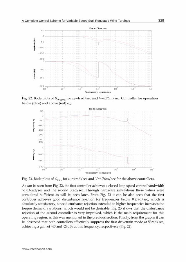
Regarding the gain scheduled controller, two PI controllers are used, with PI gains of 20 and
10 Nm/rad/sec for operation below ωΝ and 30 and 50Nm/rad/sec for operation above ωΝ.
Fig. 22 shows the Bode plots of the closed loop transfer function from the reference
rotational speed ωref (see Fig. 7) to the generator speed ω2, 罫摘認賑肉摘鉄for the two controllers
used. Fig. 23 shows the corresponding Bode plots for the disturbance transfer function from
the wind speed V to ω2, 罫蝶摘鉄. These Bode plots have been obtained for operating conditions
(V,ω)=(6.76m/sec, 4rad/sec).
www.intechopen.com
A Complete Control Scheme for Variable Speed Stall Regulated Wind Turbines 329
Fig. 22. Bode plots of 罫摘認賑肉摘鉄 for ω1=4rad/sec and V=6.76m/sec. Controller for operation
below (blue) and above (red) ωΝ.
Fig. 23. Bode plots of 罫蝶摘鉄 for ω1=4rad/sec and V=6.76m/sec for the above controllers.
As can be seen from Fig. 22, the first controller achieves a closed loop speed control bandwidth
of 0.6rad/sec and the second 3rad/sec. Through hardware simulations these values were
considered sufficient as will be seen later. From Fig. 23 it can be also seen that the first
controller achieves good disturbance rejection for frequencies below 0.2rad/sec, which is
absolutely satisfactory, since disturbance rejection extended to higher frequencies increases the
torque demand variations, which would not be desirable. Fig. 23 shows that the disturbance
rejection of the second controller is very improved, which is the main requirement for this
operating region, as this was mentioned in the previous section. Finally, from the graphs it can
be observed that both controllers effectively suppress the first drivetrain mode at 53rad/sec,
achieving a gain of -40 and -28dBs at this frequency, respectively (Fig. 22).
-200
-150
-100
-50
0
50
Mag
nitu
de (dB
)
10-2
10-1
100
101
102
103
104
-270
-180
-90
0
Pha
se (de
g)
Bode Diagram
Frequency (rad/sec)
-250
-200
-150
-100
-50
0
50
Mag
nitude
(dB
)
10-2
10-1
100
101
102
103
104
-540
-360
-180
0
180
Pha
se (de
g)
Bode Diagram
Frequency (rad/sec)
www.intechopen.com
Fundamental and Advanced Topics in Wind Power 330
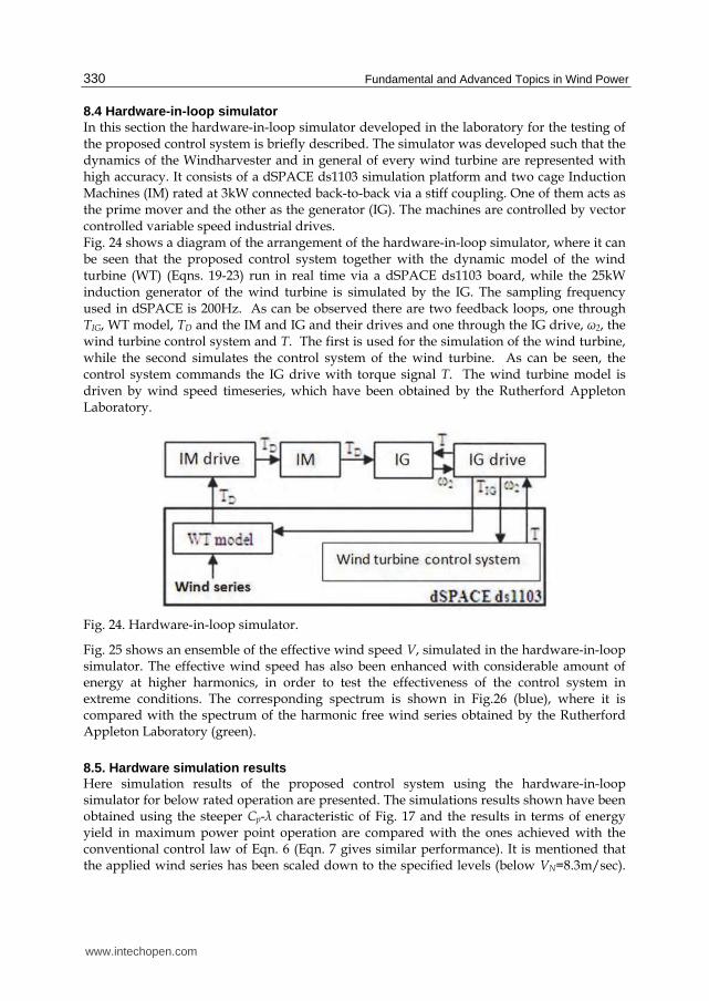
8.4 Hardware-in-loop simulator In this section the hardware-in-loop simulator developed in the laboratory for the testing of the proposed control system is briefly described. The simulator was developed such that the dynamics of the Windharvester and in general of every wind turbine are represented with high accuracy. It consists of a dSPACE ds1103 simulation platform and two cage Induction Machines (IM) rated at 3kW connected back-to-back via a stiff coupling. One of them acts as the prime mover and the other as the generator (IG). The machines are controlled by vector controlled variable speed industrial drives. Fig. 24 shows a diagram of the arrangement of the hardware-in-loop simulator, where it can be seen that the proposed control system together with the dynamic model of the wind turbine (WT) (Eqns. 19-23) run in real time via a dSPACE ds1103 board, while the 25kW induction generator of the wind turbine is simulated by the IG. The sampling frequency used in dSPACE is 200Hz. As can be observed there are two feedback loops, one through TIG, WT model, TD and the IM and IG and their drives and one through the IG drive, ω2, the wind turbine control system and Τ. Τhe first is used for the simulation of the wind turbine, while the second simulates the control system of the wind turbine. As can be seen, the control system commands the IG drive with torque signal T. The wind turbine model is driven by wind speed timeseries, which have been obtained by the Rutherford Appleton Laboratory.
Fig. 24. Hardware-in-loop simulator.
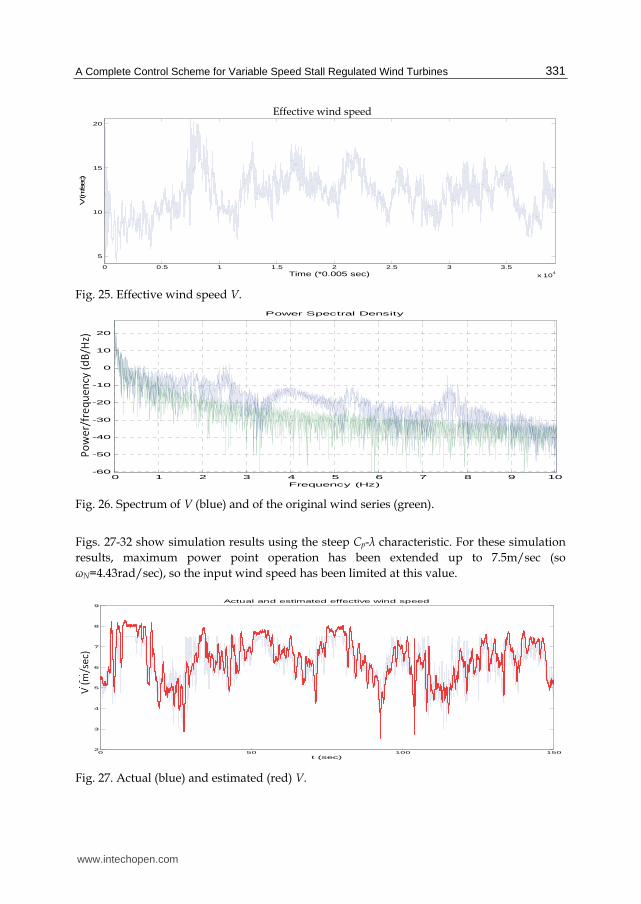
Fig. 25 shows an ensemble of the effective wind speed V, simulated in the hardware-in-loop simulator. The effective wind speed has also been enhanced with considerable amount of energy at higher harmonics, in order to test the effectiveness of the control system in extreme conditions. The corresponding spectrum is shown in Fig.26 (blue), where it is compared with the spectrum of the harmonic free wind series obtained by the Rutherford Appleton Laboratory (green).
8.5. Hardware simulation results Here simulation results of the proposed control system using the hardware-in-loop simulator for below rated operation are presented. The simulations results shown have been obtained using the steeper Cp-λ characteristic of Fig. 17 and the results in terms of energy yield in maximum power point operation are compared with the ones achieved with the conventional control law of Eqn. 6 (Eqn. 7 gives similar performance). It is mentioned that the applied wind series has been scaled down to the specified levels (below VN=8.3m/sec).
www.intechopen.com
A Complete Control Scheme for Variable Speed Stall Regulated Wind Turbines 331
Fig. 25. Effective wind speed V.
Fig. 26. Spectrum of V (blue) and of the original wind series (green).
Figs. 27-32 show simulation results using the steep Cp-λ characteristic. For these simulation
results, maximum power point operation has been extended up to 7.5m/sec (so
ωN=4.43rad/sec), so the input wind speed has been limited at this value.
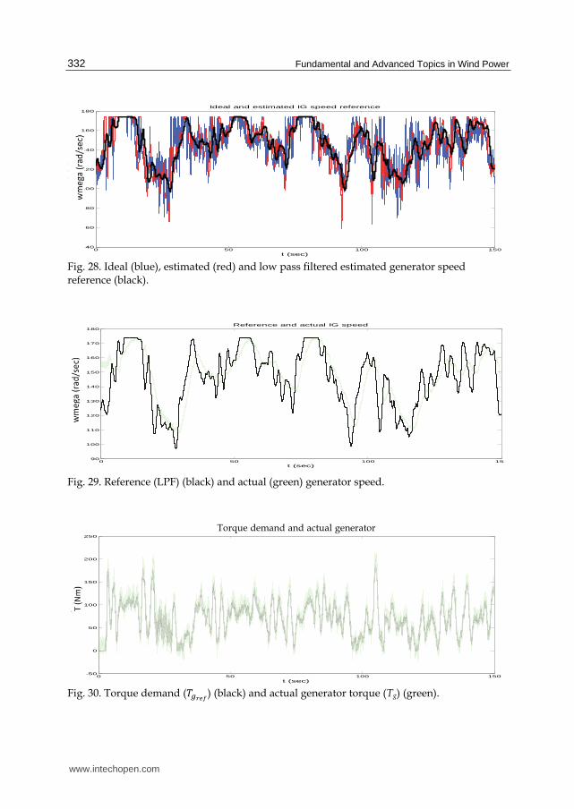
Fig. 29. Reference (LPF) (black) and actual (green) generator speed.
Fig. 30. Torque demand (劇直認賑肉) (black) and actual generator torque (Tg) (green).
0 50 100 15040
60
80
100
120
140
160
180
t (sec)
wmega (rad/sec)
Ideal and estimated IG speed reference
0 50 100 1590
100
110
120
130
140
150
160
170
180
t (sec)
wmega (rad/sec)
Reference and actual IG speed
0 50 100 150-50
0
50
100
150
200
250
t (sec)
T (Nm)
Reference and actual IG torque
Torque demand and actual generator
www.intechopen.com
A Complete Control Scheme for Variable Speed Stall Regulated Wind Turbines 333
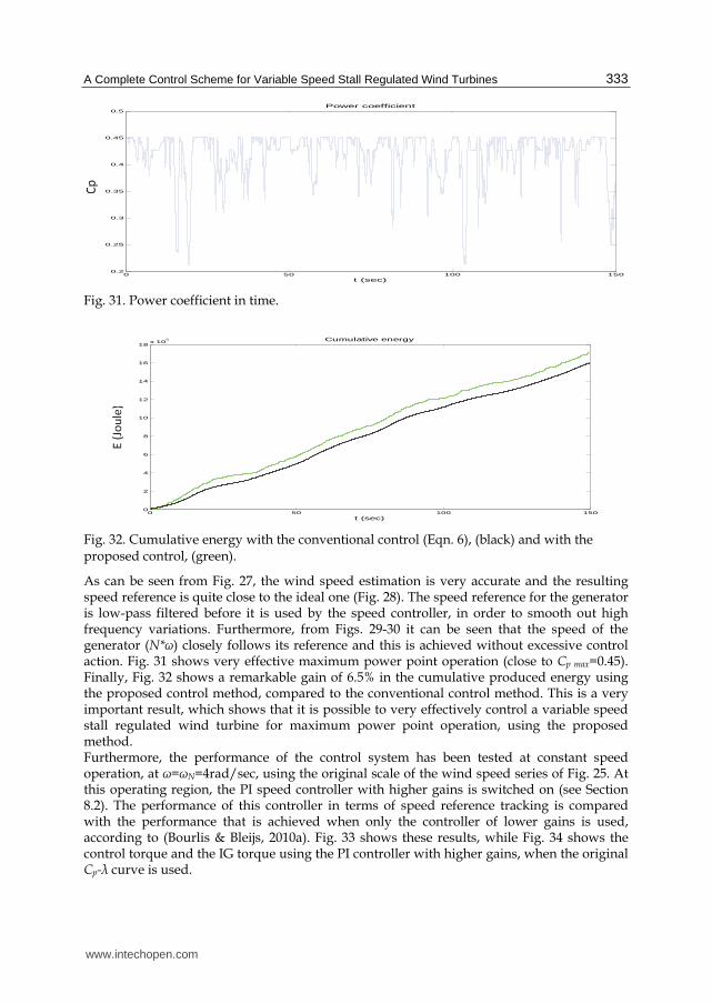
Fig. 31. Power coefficient in time.
Fig. 32. Cumulative energy with the conventional control (Eqn. 6), (black) and with the proposed control, (green).
As can be seen from Fig. 27, the wind speed estimation is very accurate and the resulting speed reference is quite close to the ideal one (Fig. 28). The speed reference for the generator is low-pass filtered before it is used by the speed controller, in order to smooth out high frequency variations. Furthermore, from Figs. 29-30 it can be seen that the speed of the generator (N*ω) closely follows its reference and this is achieved without excessive control action. Fig. 31 shows very effective maximum power point operation (close to Cp max=0.45). Finally, Fig. 32 shows a remarkable gain of 6.5% in the cumulative produced energy using the proposed control method, compared to the conventional control method. This is a very important result, which shows that it is possible to very effectively control a variable speed stall regulated wind turbine for maximum power point operation, using the proposed method. Furthermore, the performance of the control system has been tested at constant speed operation, at ω=ωΝ=4rad/sec, using the original scale of the wind speed series of Fig. 25. At this operating region, the PI speed controller with higher gains is switched on (see Section 8.2). The performance of this controller in terms of speed reference tracking is compared with the performance that is achieved when only the controller of lower gains is used, according to (Bourlis & Bleijs, 2010a). Fig. 33 shows these results, while Fig. 34 shows the control torque and the IG torque using the PI controller with higher gains, when the original Cp-λ curve is used.
0 50 100 1500.2
0.25
0.3
0.35
0.4
0.45
0.5
t (sec)
Cp
Power coefficient
0 50 100 1500
2
4
6
8
10
12
14
16
18x 10
5
t (sec)
E (Joule)
Cumulative energy
www.intechopen.com
Fundamental and Advanced Topics in Wind Power 334
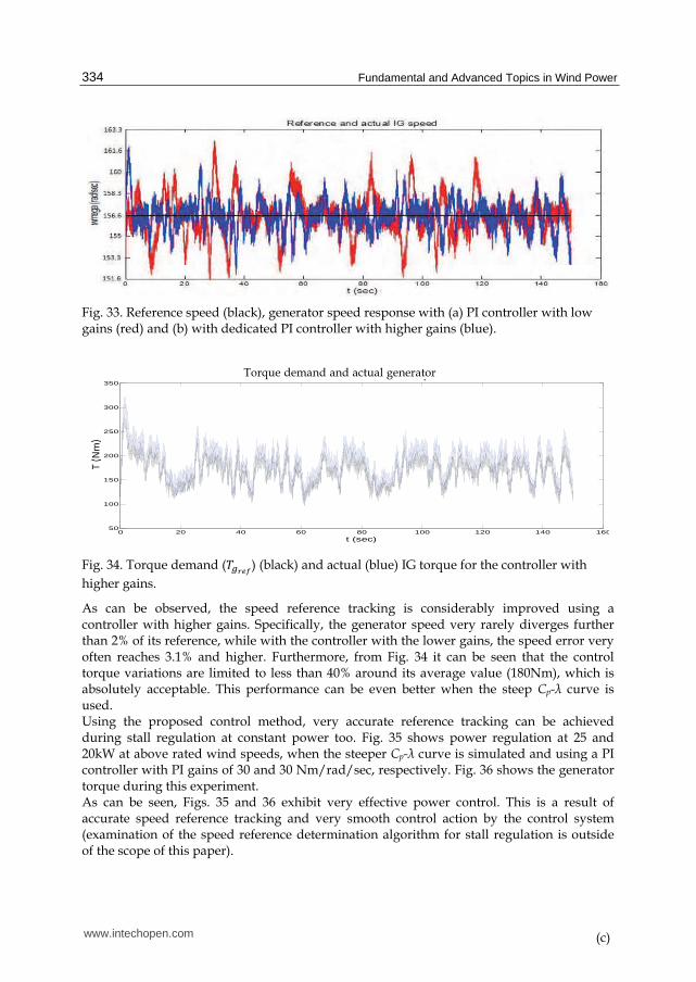
Fig. 33. Reference speed (black), generator speed response with (a) PI controller with low gains (red) and (b) with dedicated PI controller with higher gains (blue).
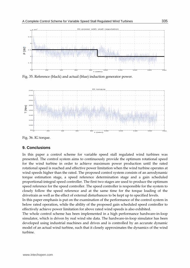
Fig. 34. Torque demand (劇直認賑肉) (black) and actual (blue) IG torque for the controller with
higher gains.
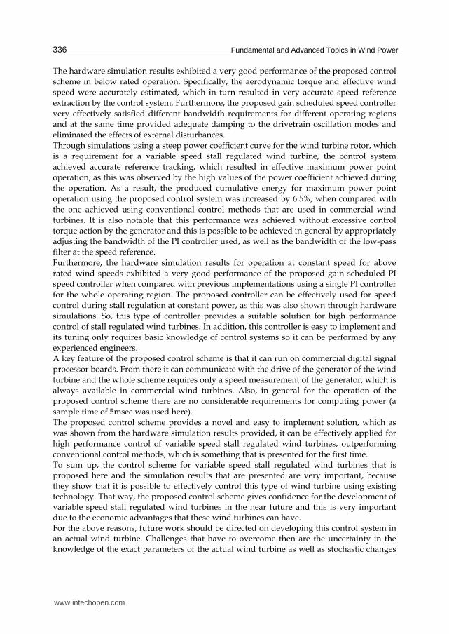
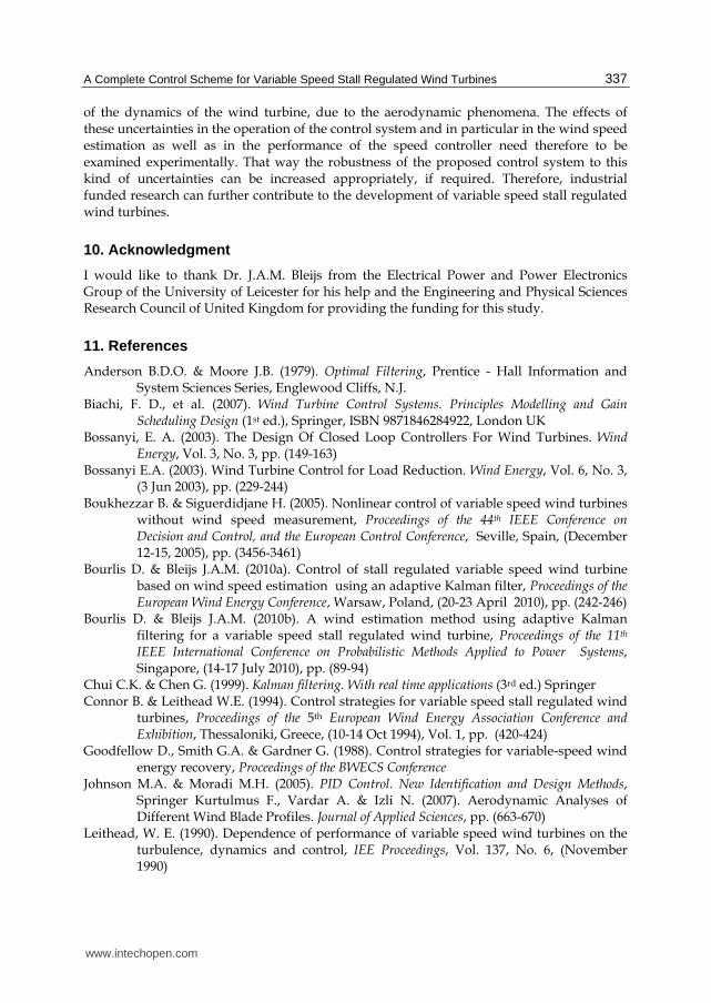
As can be observed, the speed reference tracking is considerably improved using a controller with higher gains. Specifically, the generator speed very rarely diverges further than 2% of its reference, while with the controller with the lower gains, the speed error very often reaches 3.1% and higher. Furthermore, from Fig. 34 it can be seen that the control torque variations are limited to less than 40% around its average value (180Nm), which is absolutely acceptable. This performance can be even better when the steep Cp-λ curve is used. Using the proposed control method, very accurate reference tracking can be achieved during stall regulation at constant power too. Fig. 35 shows power regulation at 25 and 20kW at above rated wind speeds, when the steeper Cp-λ curve is simulated and using a PI controller with PI gains of 30 and 30 Nm/rad/sec, respectively. Fig. 36 shows the generator torque during this experiment. As can be seen, Figs. 35 and 36 exhibit very effective power control. This is a result of accurate speed reference tracking and very smooth control action by the control system (examination of the speed reference determination algorithm for stall regulation is outside of the scope of this paper).
0 20 40 60 80 100 120 140 16050
100
150
200
250
300
350
t (sec)
T (Nm)
Reference and actual IG torque
(c)
Torque demand and actual generator
www.intechopen.com
A Complete Control Scheme for Variable Speed Stall Regulated Wind Turbines 335
Fig. 35. Reference (black) and actual (blue) induction generator power.
Fig. 36. IG torque.
9. Conclusions
In this paper a control scheme for variable speed stall regulated wind turbines was
presented. The control system aims to continuously provide the optimum rotational speed
for the wind turbine in order to achieve maximum power production until the rated
rotational speed is reached and effective power limitation when the wind turbine operates at
wind speeds higher than the rated. The proposed control system consists of an aerodynamic
torque estimation stage, a speed reference determination stage and a gain scheduled
proportional-integral speed controller. The first two stages are used to produce the optimum
speed reference for the speed controller. The speed controller is responsible for the system to
closely follow the speed reference and at the same time for the torque loading of the
drivetrain as well as the effect of external disturbances to be kept up to specified levels.
In this paper emphasis is put on the examination of the performance of the control system in
below rated operation, while the ability of the proposed gain scheduled speed controller to
effectively achieve power limitation for above rated wind speeds is also exhibited.
The whole control scheme has been implemented in a high performance hardware-in-loop
simulator, which is driven by real wind site data. The hardware-in-loop simulator has been
developed using industrial machines and drives and is controlled by an accurate dynamic
model of an actual wind turbine, such that it closely approximates the dynamics of the wind
turbine.
0 20 40 60 80 100 120 140 160 1801
1.5
2
2.5
3
3.5
4x 10
4
t (sec)
P (W)
IG power with stall regulation
0 20 40 60 80 100 120 140 160 18080
100
120
140
160
180
200
220
240
t (sec)
T (Nm)
IG torque
www.intechopen.com
Fundamental and Advanced Topics in Wind Power 336
The hardware simulation results exhibited a very good performance of the proposed control
scheme in below rated operation. Specifically, the aerodynamic torque and effective wind
speed were accurately estimated, which in turn resulted in very accurate speed reference
extraction by the control system. Furthermore, the proposed gain scheduled speed controller
very effectively satisfied different bandwidth requirements for different operating regions
and at the same time provided adequate damping to the drivetrain oscillation modes and
eliminated the effects of external disturbances.
Through simulations using a steep power coefficient curve for the wind turbine rotor, which
is a requirement for a variable speed stall regulated wind turbine, the control system
achieved accurate reference tracking, which resulted in effective maximum power point
operation, as this was observed by the high values of the power coefficient achieved during
the operation. As a result, the produced cumulative energy for maximum power point
operation using the proposed control system was increased by 6.5%, when compared with
the one achieved using conventional control methods that are used in commercial wind
turbines. It is also notable that this performance was achieved without excessive control
torque action by the generator and this is possible to be achieved in general by appropriately
adjusting the bandwidth of the PI controller used, as well as the bandwidth of the low-pass
filter at the speed reference.
Furthermore, the hardware simulation results for operation at constant speed for above
rated wind speeds exhibited a very good performance of the proposed gain scheduled PI
speed controller when compared with previous implementations using a single PI controller
for the whole operating region. The proposed controller can be effectively used for speed
control during stall regulation at constant power, as this was also shown through hardware
simulations. So, this type of controller provides a suitable solution for high performance
control of stall regulated wind turbines. In addition, this controller is easy to implement and
its tuning only requires basic knowledge of control systems so it can be performed by any
experienced engineers.
A key feature of the proposed control scheme is that it can run on commercial digital signal
processor boards. From there it can communicate with the drive of the generator of the wind
turbine and the whole scheme requires only a speed measurement of the generator, which is
always available in commercial wind turbines. Also, in general for the operation of the
proposed control scheme there are no considerable requirements for computing power (a
sample time of 5msec was used here).
The proposed control scheme provides a novel and easy to implement solution, which as
was shown from the hardware simulation results provided, it can be effectively applied for
high performance control of variable speed stall regulated wind turbines, outperforming
conventional control methods, which is something that is presented for the first time. To sum up, the control scheme for variable speed stall regulated wind turbines that is proposed here and the simulation results that are presented are very important, because they show that it is possible to effectively control this type of wind turbine using existing technology. That way, the proposed control scheme gives confidence for the development of variable speed stall regulated wind turbines in the near future and this is very important due to the economic advantages that these wind turbines can have. For the above reasons, future work should be directed on developing this control system in an actual wind turbine. Challenges that have to overcome then are the uncertainty in the knowledge of the exact parameters of the actual wind turbine as well as stochastic changes
www.intechopen.com
A Complete Control Scheme for Variable Speed Stall Regulated Wind Turbines 337
of the dynamics of the wind turbine, due to the aerodynamic phenomena. The effects of these uncertainties in the operation of the control system and in particular in the wind speed estimation as well as in the performance of the speed controller need therefore to be examined experimentally. That way the robustness of the proposed control system to this kind of uncertainties can be increased appropriately, if required. Therefore, industrial funded research can further contribute to the development of variable speed stall regulated wind turbines.
10. Acknowledgment
I would like to thank Dr. J.A.M. Bleijs from the Electrical Power and Power Electronics Group of the University of Leicester for his help and the Engineering and Physical Sciences Research Council of United Kingdom for providing the funding for this study.
11. References
Anderson B.D.O. & Moore J.B. (1979). Optimal Filtering, Prentice - Hall Information and System Sciences Series, Englewood Cliffs, N.J.
Biachi, F. D., et al. (2007). Wind Turbine Control Systems. Principles Modelling and Gain Scheduling Design (1st ed.), Springer, ISBN 9871846284922, London UK
Bossanyi, E. A. (2003). The Design Of Closed Loop Controllers For Wind Turbines. Wind Energy, Vol. 3, No. 3, pp. (149-163)
Bossanyi E.A. (2003). Wind Turbine Control for Load Reduction. Wind Energy, Vol. 6, No. 3, (3 Jun 2003), pp. (229-244)
Boukhezzar B. & Siguerdidjane H. (2005). Nonlinear control of variable speed wind turbines without wind speed measurement, Proceedings of the 44th IEEE Conference on Decision and Control, and the European Control Conference, Seville, Spain, (December 12-15, 2005), pp. (3456-3461)
Bourlis D. & Bleijs J.A.M. (2010a). Control of stall regulated variable speed wind turbine based on wind speed estimation using an adaptive Kalman filter, Proceedings of the European Wind Energy Conference, Warsaw, Poland, (20-23 April 2010), pp. (242-246)
Bourlis D. & Bleijs J.A.M. (2010b). A wind estimation method using adaptive Kalman filtering for a variable speed stall regulated wind turbine, Proceedings of the 11th IEEE International Conference on Probabilistic Methods Applied to Power Systems, Singapore, (14-17 July 2010), pp. (89-94)
Chui C.K. & Chen G. (1999). Kalman filtering. With real time applications (3rd ed.) Springer Connor B. & Leithead W.E. (1994). Control strategies for variable speed stall regulated wind
turbines, Proceedings of the 5th European Wind Energy Association Conference and Exhibition, Thessaloniki, Greece, (10-14 Oct 1994), Vol. 1, pp. (420-424)
Goodfellow D., Smith G.A. & Gardner G. (1988). Control strategies for variable-speed wind energy recovery, Proceedings of the BWECS Conference
Johnson M.A. & Moradi M.H. (2005). PID Control. New Identification and Design Methods, Springer Kurtulmus F., Vardar A. & Izli N. (2007). Aerodynamic Analyses of Different Wind Blade Profiles. Journal of Applied Sciences, pp. (663-670)
Leithead, W. E. (1990). Dependence of performance of variable speed wind turbines on the turbulence, dynamics and control, IEE Proceedings, Vol. 137, No. 6, (November 1990)
www.intechopen.com
Fundamental and Advanced Topics in Wind Power 338
Leithead W.E. & Connor B. (2000). Control of Variable Speed Wind Turbines: Design Task. International Journal of Control, Vol. 73, No. 13, pp. (1189-1212)
Manwell, J. (2002). Wind energy explained: theory, design and application, Willey Mercer A.S. & Bossanyi E.A. (1996). Stall regulation of variable speed HAWTS, Proceedings of
the European Wind Energy Conference, Göteborg, Sweden, (20-24 May 1996), pp. (825-828)
Novak P., et al. (1995). Modelling and Control of Variable-Speed Wind-Turbine Drive-System Dynamics. IEEE Control Systems Magazine, Vol. 15, No. 4, (Aug 1995), pp. (28-38)
Østergaard, K.Z., et al. (2007). Estimation of Effective Wind Speed. Journal of Physics: Conference Series, Vol. 75, No. 1, pp. (1-9)
Parker D.A. (2000). The design and development of a fully dynamic simulator for renewable energy converters, Phd Thesis, University of Leicester
Wilkie J., et al. (2002). Control Engineering. An introductory course, Palgrave
www.intechopen.com
Fundamental and Advanced Topics in Wind PowerEdited by Dr. Rupp Carriveau
ISBN 978-953-307-508-2Hard cover, 422 pagesPublisher InTechPublished online 20, June, 2011Published in print edition June, 2011
InTech ChinaUnit 405, Office Block, Hotel Equatorial Shanghai No.65, Yan An Road (West), Shanghai, 200040, China
Phone: +86-21-62489820 Fax: +86-21-62489821
As the fastest growing source of energy in the world, wind has a very important role to play in the globalenergy mix. This text covers a spectrum of leading edge topics critical to the rapidly evolving wind powerindustry. The reader is introduced to the fundamentals of wind energy aerodynamics; then essential structural,mechanical, and electrical subjects are discussed. The book is composed of three sections that include theAerodynamics and Environmental Loading of Wind Turbines, Structural and Electromechanical Elements ofWind Power Conversion, and Wind Turbine Control and System Integration. In addition to the fundamentalrudiments illustrated, the reader will be exposed to specialized applied and advanced topics including magneticsuspension bearing systems, structural health monitoring, and the optimized integration of wind power intomicro and smart grids.
How to referenceIn order to correctly reference this scholarly work, feel free to copy and paste the following:
Dimitris Bourlis (2011). A Complete Control Scheme for Variable Speed Stall Regulated Wind Turbines,Fundamental and Advanced Topics in Wind Power, Dr. Rupp Carriveau (Ed.), ISBN: 978-953-307-508-2,InTech, Available from: http://www.intechopen.com/books/fundamental-and-advanced-topics-in-wind-power/a-complete-control-scheme-for-variable-speed-stall-regulated-wind-turbines