70


NAVAL FOSTGEiiurfArB SCHOOl-
MON'VEiiBY, CALIFOBNIA 93943-BOOfc


NAVAL POSTGRADUATE SCHOOL
Monterey, California
Ttj^.^lSA COMPUTER STUDY OF AIR DEFENSE GUN
EFFECTIVENESS
by
Hyun Dae, Jung
December 1987
Thesis Advisor Robert E. Ball
Approved for public release; distribution is unlimited.
T239020


S£Cu»"^ C-A55 ' CA- s :^C-.
REPORT DOCUMENTATION PAGE
UnclassifiedId ''ESTR.C'.vE MARkaGS
2a SECURITY CuASSiPiCATiON AuTr^ORiTy
2t) DECLASSIFICATION' OOWNGRAQiNG SCHEDULE
3 OiS*Ri8UT:ON AvA.cABILi'Y Of- REPORT
Approved for Public Release;Distribution is Unlimited
i PERFORMING ORGAN, ZATION REPORT NUM8ER(S) 5 MONITORING ORGANIZATION REPORT ,MuM8ER(S)
6d NAME 0= PERFORMING ORGAN,ZA'iON
Naval Postgraduate School6d OFF CE S^MBO.
(If applicable)
67
'a NAME OF VIONTORING ORGAN, ZA'iONNaval Postgraduate School
6< ADDRESS lOfy. Sfare, ana ZiPCoae)
Monterey, California 93943-50007o ADDRESS (Cry. Sfare and ZIP Code)Monterey, California 93943-5000
ia NAME 0= F,jN0'NG . SPONSORINGORGANIZATION
8d OFFiCE SvmBOl(If applicable)
9 PROCUREMENT INSTRUMENT IDENTIFICATION NUMBER
8c. ADDRESS (Gry. Stare, and ZIP Cocel '0 SOURCE OF fjNDiNG NuMBE'S
PROGRAMELEMENT NO
PROJECTNO
TASKNO
AOP< v^NlT
ACCESS,ON NO
11 TiT.E (include Secunry Claisiticanon)
A COMPUTER STTDY OF AIR DEFENSE GUN EFFECTI\T:NESS
12 PERSONAL AuTHOR(S)
JUNG, HYUN D.^
13a TYPE OF REPORT
Master's Thesis13b 'ME COVEREDPROM
14 DATE OF REPORT1987 December
Year Month. Day) 5 PAGE CO.N'^59
16 SUPPLEMENTARY NOTATION
COSA', CODES
ciELD GROUP SuB-GROUP
'8 Su8jEC' terms (Continue on reverse if necessary and identity Oy biocx numoer)
Computer simulation of air defense for surface to aircraft.
19 ABSTRACT [Continue on reverse if neceuary and identify by biCKk number)
This Study describes the continuing development of a computer modelfor the simulation of burst kill probabilities for air defense gunsystems firing projectiles at maneuvering aircraft. The com.putersimulation developed by Keeling is modified by adding a high explosiveproximity and contact fuzed round to the simulation. The objective ofthis thesis is to develop and analyze the shipboard anti-air defenseproblem in order to choose the best air defense gun system. The airdefense gun system studied consists of a 40 mm gun, firing fragmentingproximity and contact fuzed projectiles, an early warning radar system,and a fire control system. The aircraft vulnerability and the gun dataused in this thesis are entirely synthetic to avoid securityclassification problems.
20 DiS'R'BuTiON AVAILABILITY OF ABSTRACT
S UNCLASSIFIED/UNLIMITED D SAME AS RPT dtiC uSEPS
2' ABSTRACT SECURITY ClASSiFiCATiON
Unclassifiedi2a NAME OF RESPONSIBLE iNOiviDuAl
Robert E. Ball22b TELEPHONE f/nc/i/oe Area Code) 22c OFFiCE SYMBOL("408) 646-2885 67Bp
DD FORM 1473, s-imar 83 APR ed tc^ Tiay oe useo uhth exnaustea
All other editions are oosoieteSECURITY C-ASSiFiCAT:ON 0^ 'S 'AGE
Bus Go«trnmtnl »T,nl,rn 0"iCt lilt—(0(}4J

Approved for public release; distribution is unlimited.
A Computer Study of Air Defense Gun Effectiveness
by
Hyun Dae. JungLieutenant Commander, Republic of Korean Na\7
B.S., Korean Naval Academy, 1976
Submitted in partial fulfillment of the
requirements for the degree of
MASTER OF SCIENCE IN ENGINEERING SCIENCE
from the
NAVAL POSTGRADUATE SCHOOLDecember 19S7
ABSTRACT
This study describes the continuing development of a computer model for the
simulation of burst kill probabilities for air defense gun systems firing projectiles at
maneuvering aircraft. The computer simulation developed by Keeling is modified by
adding a high explosive proximity and contact fuzed round to the simulation. The
objective of this thesis is to develop and analyze the shipboard anti-air defense problem
in order to choose the best air defense gun system. The air defense gun system studied
consists of a 40 mm gun, firing fragmenting proximity and contact fuzed projectiles, an
early warning radar system, and a fire control system. The aircraft vulnerability and
the gun data used in this thesis are entirely synthetic to avoid security classification
problems.

TABLE OF CONTENTS
I. INTRODUCTION 10
A. BACKGROUND 10
B. OBJECTIVE 10
C APPROACHING THE PROBLEM 11
D. ORGANIZATION OF THE MODEL 12
« 1. Scenario 12
2. Model Input 13
II. PROXIMITY FUZED WARHEAD 14
A. BASIC THEORY 14
B. TARGET SUSCEPTIBILITY 14
C. MISS DISTANCE 15
D. THE FUZE 16
E. TARGET VULNER.ABILITY 16
1. State Transition Matrix Method 17
2. Vulnerability Model for Externally Detonating
Warheads 17
F- Prss 17
G. PROBABILITY OF KILL GIVEN A BURST 20
III. CONTACT FUZED WARHEAD 21
A. TARGET SUSCEPTIBILITY 21
B. TARGET VULNERABILITY 21
C- PkSS ^2
D. PROBABILITY OF KILL GIVEN A BURST 22
IV. COMPUTER PROGRAM 23
A. MAIN PROGR.AM 23
B. SUBROUTINES 23
1. Initiation 23
DUDLEY KFOX LIBBABVNAVAL POSTGRADOAT}; -inHOOL
M01JTEB.EY, CALIFOEi\)i.ti yby^S-BOOa
2. Generation 23
3. Calculation 23
4. Susceptibility 24
5. Vulnerability 25
6. Random Number 25
C. SUBROUTINE PROXFUZE 25
D. SUBROUTINE CONTFUZE 25
E. SUBROUTINE BURSTKILL 25
V. ANALYSIS AND CONCLUSIONS 26
A. TYPE OF FUZE 26
B. BALLISTIC DISPERSION 26
C. R.'XNGE EVALUATION 26
D. EFFECTS OF TARGET MANEUVERS 2S
E. EFFECTS OF RADAR ERROR 28
F. EFFECTS OF MUZZLE VELOCITY AND RATE OFFIRE 29
G. CONCLUSIONS 29
APPENDIX A: APL COMPUTER PROGRAM 34
I. KEELINGS PROGRAM 34
APPENDIX B: APL COMPUTER PROGRAM 41
1. NEW PROGR.AM 41
APPENDIX C: SYMBOL NOTATION 47
APPENDIX D: EQUATIONS AND DATA 49
1. GOVERNING EQUATIONS 49
a. The Siacci Formula 49
b. Range of the Projectile 49
c. Gravity Drop 49
2. DATA 49
APPENDIX E: EMPIRICAL COMPARISON OF MARGINALDISTRIBUTIONS 51
1. TYPE OF FUZE 51

a. Proximity Fuzed Warhead 51
b. Contact Fuzed Warhead 51
2. BALLISTIC DISPERSION 52
3. RANGE EVALUATION 52
4. EFFECTS OF TARGET MANEUVERS 53
a. Maneuvering Target 53
b. Non-maneuvering Target 53
5. EFFECTS OF R^ADAR ERROR 54
6. EFFECTS OF MUZZLE VELOCITY AND RATE OFFIRE 54
a. Muzzle Velocity 54
b. Rate of Fire 55
LIST OF REFERENCES 56
INITIAL DISTRIBUTION LIST 57
LIST OF TABLES
L 40 MM GUN CHARACTERISTICS 50
2. PROXIMITY FUZED WARHEAD 51
3. CONTACT FUZED WARHEAD 51
4. BALLISTIC DISPERSION 52
5. RANGE EVALUATION 52
6. MANEUVERING TARGET 53
7. NON-MANEUVERING TARGET 53
8. RADAR ERROR 54
9. MUZZLE VELOCITY 54
10. R.ATE OF FIRE 55

LIST OF FIGURES
1 . 1 Playing Area of The X, Y & Z Plane 11
2.1 Ballistic Dispersion, Bias, and CPA 15
2.2 Pj^Y)
Function of X and Y 18
2.3 Efiect of Angular Dispersion with Range 19
4. 1 Flowchart of Computer Program 24
5.1 Graphical Comparison of Fuze on 40 MM gun Lethality 27
5.2 Effects of Ballistic Dispersion on 40 MM gun lethality 28
5.3 EfTects of Range on 40 MM Gun Lethality 29
5.4 EfTects of Maneuver and Non-maneuver on 40 MM Gun lethality 30
5.5 Effects of Radar Error on 40 MM Gun Lethality 31
5.6 Efiects of Muzzle Velocity on 40 MM Gun Lethality 32
5.7 EfTects of^ Firing Rate on 40 MM Gun Lethality 33

ACKNOWLEDGEMENT
I would like to express my sincere appreciation to my thesis advisor, Dr. Robert
E. Ball, Aeronautics Engineering Department of the U. S. Naval Postgraduate School.
I thank my wife and two son for their support and patience away from our home
during two and half years in the United States America.
Finally, I would also like acknowledge the Republic of Korean Nav>- for the
opportunity to attend the Naval Postgraduate School.

I. INTRODUCTION
A. BACKGROUNDIn modern times it often occurs that during battle, friendly ships are threatened
by enemy aircraft. This thesis focuses on a ship's ability to defend itself against aircraft
with a 40 mm gun system. The computer program presented in this paper is a
modification of a simulation written in the A Programming Language(APL) by Capt.
C. Keeling. [Ref. 1] Keeling's program simulates engagements between air defense gun
systems firing non-explosive projectiles at maneuvering aircraft. In his thesis, Keeling
suggested further research on proximity fuzed and contact fuzed high explosive(HE)
rounds. This paper expands Keeling's simulation to include the HE round with both a
contact fuze and a proximity fuze
The simulation shows how changing gun parameters can affect a gun system's
probabiUty of kill against an aircraft. These parameters include: target range, projectile
size, ballistic dispersion, muzzle velocity, firing rate, radar error, linear fire control, type
of fuze (a new feature) and aircraft probability of kill given a hit or warhead lethal
radius (a new feature). The use of this program increases the information available on
the effectiveness o[ gun systems with and without HE warheads. The ultimate
measure of success in the design and performance of an air defense gun system is the
ability of the system to shoot down low-flying hostile aircraft within the combat
environment.
B. OBJECTIVE
The objective of this thesis is to continue the development of a computer model
that will be helpful in making decisions regarding the design and operation of an air
defense gun system. In this thesis, the program is used to gain insight into how each
of the design parameters of the gun system affect the probability of kill and which of
the parameters are most important in the gun system design for air defense. In
particular, the influence of the HE round on gun effectiveness will be studied.
10

C. APPROACHING THE PROBLEMThe gun system is located on a ship at the origin of an X, Y, and Z coordinate
system. The playing area for the model is the quarter of a hemi-sphere entirely within
the first quadrant of the X, Y and Z plane as shown in Figure 1.1. The size of the
playing area may be adjusted by modifying the program's source code.
ZA
PRESENT POSITION
TARGET^FUTURE POSITION ^ "
^^ ^ ^RESENT sIaNT RANGE
/y
FUTURE SLANT RANGE/
/LINE OF FIRE ^^
// y
/
LINE OF SIGHT
V
Figure 1.1 Playing Area of The X, Y & Z Plane.
11

The model assumes one-on-one engagements, no suppressive fire from the aircraft,
and no terrain effects. The target is not necessarily attacking the gun system and
may or may not maneuver while within the gun's effective range.
D. ORGANIZATION OF THE MODELThe air defense system consists of an early warning system, a tracking radar, a
weapon control system and a gun with one or more barrels. The model studied here is
a twin 40 mm gun using high explosive rounds located onboard the ship at the origin
of the playing area. As an aircraft enters into the radar detection envelope of the early
warning radar, the aircraft is detected and identified as hostile by the ship. The
tracking radar is given the targets position. This radar tracks the aircraft and
continuously computes the target range, elevation, azimuth, and velocity. The gun fire
control computer solves for the lead angle in azimuth and elevation based on the
calculated target positional data assuming no target maneuvering. The gun is
positioned at the lead angle and fires a burst of proximity or contact fuzed high
explosive rounds. The projectiles fiy out toward the moving target. The target
continues on its randomly selected flight path. The miss distance and assumed ballistic
dispersion are used in the model to determine the probabihty of aircraft kill for each
round Pr'sc- For the proximity fuzed warheads, the projectiles do not have to hit the
target to cause damage. The probability of aircraft kill given a detonation, Pj^ j^,is
determined using the Carlton difiused Gaussian kill function . For the contact fuzed
warheads, the projectiles must hit the target in order to cause damage. The probability
the aircraft is killed given the hit on the target, Piru is represented by the two-
dimensional Carlton hit function.
I. Scenario
The general approach in this model is the development of the kill probability
for one gun system firing one burst at one randomly maneuvering target. The
probability of kill for each round is used to compute a burst kill probability. The gun
system computes target flight path characteristics, predicts a time-dependent intercept
point in space, positions the gun and fires the projectiles. For contact fuzed HE
rounds, the target vulnerability is represented by a vulnerable area (A^) in a plane in
space that is perpendicular to the slant range (R) between the gun and the center of
the target. For the proximity fuzed warhead, the target vulnerabihty is represented by
a lethal radius.
1.

2. Model Input
Inputs are required for the gun, the fuze, the target, and ranges of
engagement. Gun inputs are muzzle velocity, projectile coefficient of drag, burst size,
rate of fire, and angular ballistic dispersion. The fuze input is the probability of fuzing,
which is independent of range. Aircraft inputs are velocity, altitude, acceleration
performance capabilities, and vulnerability data based on the type and size of
projectile and fuze being used. A flight path generates, for several different types of
aircraft, maneuvers using a Monte Carlo simulation.
13

II. PROXIMITY FUZED WARHEAD
A. BASIC THEORY
A proxirmty fuze detects the target and causes detonation of the high explosive
warhead in the vicinity oi^ the target. A warhead usually contains a powerful but
relatively insensitive high-explosive that can only be initiated by the heat and energy
from the primar\' explosive in the fuze [Ref 3]. Proximity fuzes accomplish their
purpose through "influence sensing" with no contact between the projectile and the
target . These fuzes are actuated by some characteristic feature of the target, such as a
reflected radio signal, an induced magnetic fleld, an interrupted Ught wave, a pressure
measurement, or an acoustical impulse. "Proximity sensing" results in detonation of
the bursting charge in the vicinity of the target or targets. A direct hit is not necessary
to disable an aircraft and achieve the desired effect. An aircraft may be damaged in
any part of the large volume occupied by fragments from the exploding round. Since
several air targets may exist simultaneously, the sensing equipment must be able to
isolate a selected target. Proximity fuzing had its origins in England early in World
War II. Proximity fuzing is represented as VT fuzing (a code name used during Word
War II to imply variable time fuzing) [Ref 2 p. 76].
B. TARGET SUSCEPTIBILITY
The modeling and quantification of the individual events and elements in an air
defense encounter is referred to as a susceptibility assessment. SusceptibiHty is the
inability of an aircraft to avoid being damaged in the pursuit of its mission, to its
probabiUty of being hit [Ref 2] The level of susceptibility of an aircraft in encounter
with a threat is dependent upon three major factors:
• The scenario includes the physical environment in which the encounter takes
place, the air defense deployment and activity, and the aircraft flight path and
tactics, including any supporting forces.
• The air defense characteristics, operations, and lethality.
• The aircraft observables or detectable signatures, any countermeasures used, the
aircraft performance capabilities, and any self-protection armament are the
important factors associated with the aircraft itself
14

One of the most important susceptibility measures is the closest point of
approach or miss distance of a projectile to a maneuvering target.
In general, the smaller the miss distance, the more hkeiy the aircraft n^HU be hit.
Whether or not the aircraft is hit depends upon the presented area of the aircraft. This
study assumed the presented area A_ of the aircraft is based on the six cardinal sides.
The most the projectile can see in the intercept plane is part of three sides. The threat
aircraft used in the study has a presented area from the area of the top A^q_ (50 m ,
equal to the bottom), the area of the side A^-^^g (30 m , the same on each side), and
the area of the front A^j.^^^^ (5 m"^, equal to the rear).
C. MISS DISTANCE
As shown in Figure 2.1, the CPA is the mean value for an assumed Gaussian
distribution of the projectile miss distance and the ballistic dispersion is the round to
round variance about that point.
<Jdx
'/^-^ • %
- xr^^^ ^
Figure 2.1 Ballistic Dispersion, Bias, and CPA.
The miss distance form for the round is given by
^*bx' + ^»by'= CPA^ (eqn 2.1)
15

where
• (Hbx '^v^ ^^ ^^^ mean or bias in the x and y direction.
D. THE FUZE
The function of the fuze is to initiate the detonation of a warhead at a time and
place such that maximum damage will be inflicted upon the target. Since the warhead
damage volume is preset, the achievement of maximum damage depends on the time of
fuze initiation [Ref. 3]. The fuze package consists of a safety-and-arming device to
keep the weapon safe until it is deployed and clear of friendly forces, a detonator to
initiate the HE charge detonation, a device that senses the presence of a target (known
as the target detection device (TDD)), and a logic circuit that initiates detonation at
the proper time.
The functioning of a fuze can be represented by the probability P. which may or
may not be dependent upon the miss distance. For example, a proximity fuze with an
80*^/0 probabihty of detonating the warhead within a miss distance range r, of 100 ft
and a O'^o probability beyond r, can be modeled in the form
P|<x.y) = 0.8 when(x-+ y-)^'- < 100ft
P^x.y) = when(x-+ y^)^'- > 100ft
E. T.ARGET VULNERABILITY
Vulnerability refers to the inability of the aircraft to withstand one or more hits
by the damage mechanisms, to its vincibihty, to its liability to serious damage or
destruction when hit by gun fire [Ref 2]. The critical components on an aircraft are
those components which, if either damaged or destroyed, would lead to an aircraft kill.
A general procedure has been developed for determining the critical components, their
possible damage or failure modes, and the etlects of the component damage or failure
upon the continued operation of the aircraft. The procedure consists of
• .A. selection of the aircraft kill levels or categories to be considered.
• .A.n assembly of the technical and functional description of the aircraft.
• The determination of the aircraft components of the aircraft and their damage
caused failure modes for the selected kill levels.
16
1
.
State Transition Matrix Method
The study by Keeling used the state transition matrix method to describe the
damage state of the aircraft after one or more hits. This method allows the
consideration of redundancy in the critical components and accounts for the fact that a
single shot cannot kill more than one redundant critical component. This method
states that a sequence of independent events can be modeled as a Vlarkov process.
The state space of the Markov process includes kill of the aircraft, no kill of the
aircraft, a state space for a kill of each of the critical redundant components, and
combinations of kills of redundant critical components that eventually lead to a kill of
the aircraft., The state of the target at the begining of the engagement is represented
as the initial state vector S . One transition represents the state of the target after one
random hit on the aircraft, and SJ represents the state of the target after the j hit.
The matrix that accounts for the transition is |T.\I|. Thus
SJ+1 = |TM| SJ (eqn2.2)
The state transition matrix method is not appropriate for che HE round.
2. Vulnerability Model for Externally Detonating Warheads
For the proximity fuzed HE rounds, the aircraft's vulnerability can be
represented by a Pj^ q function of x and y proposed by Carlton
PkD" exp(-.\^, ro'^)*exp(-y^/ro^) (eqn 2.3)
The scaling parameter Tq can be related to the warhead lethal radius r^, such that when
r = r|, Pjr Q = 0.5. Collocating the one-dimensional Carlton kill function through 0.5
when r= r^ gives Tq= 1.20 r^ as shown in Figure 2.2.
^' ^'kss
This simulation uses the circular Carlton kill function method as presented by
Ball [Ref 2 p. 320]. The equation for P^^^ is
PKSS = ^o'^(«'''P^''^)''^^P(-<^*bx'«HMby'P)) (eqn 2.4)
where
17

1
075
\^p Q50
\j\
025
: liTHAL RADIUS
-CPA
Figure 2.2 Pj^ q Function of X and Y.
a IS (2(T,^2 ^ ,^2)
Pis(2cr,y2 +
((Tj^.dj^.) is the ballistic dispersion of the round in the x and y direction.
Tq' is a scahng parameter of the warhead lethal radius r. such that rQ= 1.2rj.
Pj. is the probability of fuzing (assumed constant).
The calculation of the probability of kill for a variety of ranges is made simpler
by using angular errors for the dispersion errors. From the Figure 2.3 it can be seen
that a^j and a^2 ^^^ ^^^ angles representing the angular standard deviation of the
dispersion errors about the closest point of approach. Figure 2.3 shows that
^dx ~ ^'dx^ (eqn 2.5)
where
adxl= adx2
= adx• a^^ is the angular ballistic dispersion in the x direction.
By the same theory in the y direction can be shown to be
18

% = «dy^where a^^y is the angular ballistic dispersion in the y direction.
Figure 2.3 Effect of Angular Dispersion with Range.
Furthermore assumption is made that the angular ballistic dispersion as shown in
Figure 2.2 is the same in both direction, hence
«dx = «dy = «
The equation for the Carlton kill function model, Equation 2.3, simplifies to
PkSS = (^O^Pf' V) * exp(-(Mbx^+ Mby^)''(V)) (eqn 2.6)
where
y is(2a^R^ + r^^)
The final form for the probability of kill is obtained by using Equation 2.1, giving
PkSS = ^'6^^[^ y)*exp{-CPA2/ y) (eqn 2.7)
For this study, r| is taken as five meters. Thus, rQ is six meters.
19

G. PROBABILITY OF KILL GIVEN A BURST
The probability of an aircraft kill for a burst of rounds is directly proportional to
the probability there is a clear line of sight from the detecting element to the aircraft.
Given that the aircraft has been detected, the probability that one or more propagators
will be fired at the aircraft is detonated by Pp. Thus, the probability that the aircraft is
killed by one shot in an encounter, Pj(^/£ is given [Ref 2. p. 320] by
• Pq is the probability that the aircraft has been detected from the start of a
search up to the present time t.
• Pp is the probability that a propagator will be fired at the aircraft.
• This study assumes that Pq* Pp = 1.
The probability that the aircraft is killed by the sequence of N gun shots is unity
minus the product of the individual probabilities of survival for each shot. Thus, for
the burst of N rounds Pj^^ss '^ Equation 2.8 is replaced with
N
^KlBurst= l-n[l-^m.] (eqn2.9)
»=i
where the subscript i denotes the ith shot.
20

III. CONTACT FUZED WARHEAD
Contact fuzes detonate the HE warhead upon contact with the target.
Detonation can be made to occur on the surface or inside the target, depending upon
the desisn of the fuze.
A. TARGET SUSCEPTIBILITY
The presented area A of the aircraft is defined to be the area of the aircraft seen
by the projectile in a plane normal to the path of the projectile at intercept. The
procedure for determining the presented area seen by the round is determined based
upon the difference between the projectile's velocity and the relative velocity of the
projectile with respect to the aircraft. This procedure is described in detail in [Ref 1].
B. TARGET VULNERABILITY
For warheads that do not use a proximity fuze, such as small arms and HE
warheads with contact fuzes, a hit on the aircraft must occur to cause damage. Thus,
the kill function that defines the probability the target is killed due to a propagator
becomes ?^ pj for random hits, and integration is carried out over the extent of the
aircraft. In this approach, the probability the aircraft is hit by the propagator, Pj^. is
computed and multiplied by the probability the aircraft is killed given the random hit
on the aircraft, Pj^ j^. The computation of Pj^ is developed by KeeUng and
accomplished using the Carlton hit function. The aircraft vulnerabiUty is represented
by its vulnerable area Ay, centered at the aim point, and any hit on the vulnerable
area causes a kill. The computation for the vulnerable area is the product of presented
area Ap and the probability the aircraft is killed given the random hit on the aircraft
Pk H [R^f- 21
Av= Pk;H*^P (^^^ ^-^^
This model assumes the Pj<^ j^ value for the round is 0.25, and Ay is given as
Ay= 0.25-' Ap (eqn 3.2)
21
c.
21.
KSSThis simulation uses the Carton kill function for the Pj^ss ^^ presented in [Ref
P =2 2 1/2 2 2 1/2
exp
-^^, -^^A,
\-
[(2tzg\xq) (2KG\yl)}
(eqn 3.3)
The product of Xq and Vq can be taken as (l)equal to the presented area, Ap, or (2)
equal to the vulnerable area, Ay (see Ref 2, PP 316-315). This study assumes Xq = Vq
and uses Ap for the product. The means and deviations in Equation 3.3 are
determined in the same manners as was done for the proximity fuzed round in Chapter
II. Thus, the final form for the probability of kill given a single shot becomes
^KSS" {25)Ap,{2na-R^ + Ap^)*exp{-nC?A^,{2na-R? + Ap^)} (eqn 3.4)
D. PROBABILITY OF KILL GIVEN A BURST
When multiple shots are considered, the single hit P|^/h is used for each shot.
To determine the probabihty of an aircraft kill for a burst of rounds, the same
procedure uses for the proximity fuzed warhead is used. Thus,
N
KiBurst = i-n \-pKSSi
(eqn 3.5)
i=l
22

IV. COMPUTER PROGRAM
Keeling's program is modified by adding subroucmes PROXFUZE, CONTFUZE,
BL'RSTKILL. and by changing the appropriate data to a 40 mm gun. This computer
program consists of a main program and utilizes fifteen subroutmes. The program was
written in the A Programing Language (APL). The computer program listing is shown
in APPENDIX A, and a flowchart of the program is depicted in Figure 4.1.
A. MAIN PROGRAMThe main program uses a DRIVER program for initiating simulation and probes
the user for mputs. The program DRIVER calls the GUN subroutine for simulating
gun fire solution. After the simulation has been initiated, subroutine GUN simulates
the air defense engagement by utilizing the appropriate subroutines necessarv' to
simulate the engagement of an aircraft by the on-board ship air defense gun.
Subroutine GUN collects statistics on the probabihty of kill and where the actual slant
range of intercept occurred. These data are then sent back to the main program
DRIVER.
B. SUBROUTINES
1. Initiation
Subroutine GUN simulates the air defense engagement by calling the
appropriate subroutines necessar>' to simulate the engagement of the aircraft by the on-
board ship air defense gun.
2. Generation
The generation of a situation for air defense, aircraft's position, the radar
located position with radar errors, and flight path maneuver of aircraft is subroutines
lUANGECHEK, R.'XDAR, and AIRCIUAFT.
3. Calculation
Subroutines INTERCEPT, MISSDIST, and MISSVECTOR are used to
determine the predicted intercept point for the median round in the burst and the
closest point of approach for each round in the burst.
23

DRIVER
GUN
RANGECHECK UNTF
\
'"1
RADAR NORRNAD UNIRANDj
' ff
AIRCRAFT UNIF
1
'
INTERCEPT
r^1
MISSVECTOR MISSDIST APDATA UNIF
PKVECTORHproxfuze
i-CONTFUZE —J
BURSTKILL
( STOP j
Figure 4.1 Flowchart of Computer Program..
4. Susceptibility
Subroutines APDATA, PKVECTOR, CONTFUZE, and PROXFLZE are
used in determining the susceptibility of the aircraft. APDATA determines the
24

presented area of the aircraft that is used in the Carlton kill function model in
subroutine CONTFUZE. PKVECTOR stores the data for each round in the burst.
5. Vulnerability
Subroutines PKVECTOR, CONTFUZE, PROXFUZE. and BURSTKILL are
used in determining the vulnerability of the aircraft. Subroutine PKVECTOR stores the
data for each round in the probability of kill. Subroutine CONTFUZE and
PROXFUZE are used in determining the probability of kill for a single shot whether or
not the projectile hit the target.
6. Random Number
Subroutines UNTF. UNI RAND, and NORRAND are used to generate the
random number required in the simulation. Subroutine UNTF generates uniform
random numbers in the interval(a, b). UNI RAND generates pseudo-uniform random
numbers. NORR.A.ND is the generation of normal random numbers.
C. SUBROUTINE PROXFUZE
Subroutine PROXFUZE is used in determining the probability of kill for a single
shot of the HE proximity fuzed round. This vulnerability data is used by subroutine
BURSTKILL to determine the probability of kill given burst.
D. SUBROUTINE CONTFUZE
Subroutine CONTFUZE is used in determining the probability of kill for a single shot
of the HE contact fuzed round. This vulnerability data is used in subroutine
BURSTKILL to determine the probability of kill given burst.
E. SUBROUTINE BURSTKILL
Subroutine BURSTKILL determined the probability of kill for a given burst.
This probability of kill data uses the vulnerability of the aircraft.
25

V. ANALYSIS AND CONCLUSIONS
This program model was initiated with the realization that the probability of kill
is one measure of effectiveness that has a broad base application in the field of air
defense gun system evaluation. This program for determining gun system probability
of kill has simulated several parameters. These parameters describe the gun. target
environments, and engagement procedures whereby one gun system encounters one
maneuvering target. The data used is given in APPENDIX D. This study uses a box
plot to illustrate the effects of several important parameters. This graphical
imformation gives a quick sense for the distribution of Pj^ for the individual test
values of each of^ the parameters. The vertical box contains the middle fifty percent oi^
the distribution, and the individual dots show all the outhers. The mean value of the
probability of kill at each of the test value settings are connected with a line. The result
of each simulation is Usted with the Empirical Statistics table in APPENDIX E.
A. TYPE OF FUZE
The probability of kill of the aircraft in a one-on-one encounter with both the
proximity fuzed warhead and the contact fuzed warhead, Pp; 5. is shown in Figure
5.1. The effects that a proximity and a contact fuzed warhead have on the lethality of
the 40 mm gun using a HE rounds can be seen in this Figure. The proximity fuzed
warhead shows a higher probabiUty of kill given a burst than the contact fuzed
warhead against a maneuvering target. Consequently, the remaining studies
concentrate on the proximity fuzed warhead.
B. BALLISTIC DISPERSION
Figure 5.2 shows an example of how the 40 mm gun probability of kill changes
with angular dispersion. The degree of dispersion can immediately be seen, as well as
how many of the data points were considered as outliers. Since the dispersion settings
for optimality is arbitrary in this range, the assumption is made that the dispersion
angle for the gun is 1.0 milliradians.
C. RANGE EVALUATION
The evaluation of the Pj^ for different range values was conducted for the
maneuvering target. The maneuvering target was engaged by one burst for each range
26

-sJf
LTTHALITY OF PROXIMfTY FUZE
400 SOO 1200 1600
RAA4CE IN METERS
LTTHALrTY OF CONTACT FUZE
400 800 1 200
RANGE IN METERS
LETHALfTY OF CONTACT FUZE
1600
Figure 5.1 Graphical Comparison of Fuze on 40 MM gun Lethality.
value. The gun produced the highest probability of kill at the 700 meters, and the
efTective range was 1300meters against the maneuvering target. The air defense for a
real situation requires about 2000meters for successful engagement.
27

EFFECT OF ANGULAR DISPERSION
5> : ! : 1
^ • » . .»
o•
-:
1
t
[ 5 '
1
1^S IT
•
^-
•
IS - t
sa.
'l t
o
-
r
Bl t. 1 1 1
r.t*\
AM
cr* iKio-' 1.5X 10-> 2«1
4SICULAA OtSPOfSiON i4 RAOtAI
Figure 5.2 Eflects of Ballistic Dispersion on 40 MM gun lethality.
D. EFFECTS OF TARGET MANEUVERS
Figure 5.4 shows the elTects that a maneuvering and non -maneuvering target
have on the lethality of the 40 mm gun. Against the non-maneuvering aircraft, the
probability of kill given a burst is about twice that for the maneuvering target. That
means that the lethality of the air defense gun requires a non linear fire control
predictor based upon the tactical air combat maneuver(TACM).
E. EFFECTS OF RADAR ERROR
Figure 5.5 shows the effect of radar error on the 40 mm gun. In today's combat
environment, the radar accuracy is an important factor. That means a large
improvement in lethality can be obtained by reducing the radar error. The 100 percent
error represents the current state of the radar system, so greater or less than 100
percent reflects great differences in lethality due to technological improvements to
today's radar system.
28

EFFtCTS OF RAMCeS ON 40 MM GUN
1200
RANCC M yniRSitoo
Figure 5.3 Efiects of Range on 40 MM Gun Lethality.
F. EFFECTS OF MUZZLE VELOCITY AND RATE OF FIRE
Increased rate of fire and muzzle velocity can significantly improve the
probability of kill for the rounds in the burst, as shown in Figures 5.6 and 5.7.
Increasing the rate of fire decreases the time between projectiles, which means there are
more projectiles in the area of where the aircraft is at intercept. Thus, the probability
of kill is increased for each round in the burst. Increasing muzzle velocity decreases
the time required to get to the target, and thereby reduces the effects of target
maneuver.
G. CONCLUSIONS
This study has been conducted from a theoretical and intuitive point of view with
conclusions withheld in many cases pending vaUdation. The execution of this program
demonstrated what appear to be some clear improvements is gun lethality. The sample
results in each of the graphs show the difference in the probability of kill values. They
represent a convenient and practical base from which to study or perform parametric
analyses on existing systems or on systems still on the drawing board. The 40 mm gun
with the proximity fuzed warhead considered here for the given scenario and target
29

CrFECT OF MANEUVERING TARGET
e
J• •b
s. *—i T \ :t_i \^w • •
1O o 1
>-1
t -« \_j
tn « •
So \oa.
"• \
1
1•
Co
O-
J^^"^^4-~-_o J 1 , , * . 2 !—1—
«
400 aOO 1200 !600RANGE IN UUrZRS
tl-FLCT OF NON-MANEUVOTINC TARCTT
e^ 1 •
*y t
•
^o
^ : 1
>c
isS
g •
9 *
d
:
•
o1 i
^^^
400 800 1200 t«00
MMCE M WnOtS
Figure 5.4 EfTects of Maneuver and Non-maneuver on 40 MM Gun lethality.
vulnerability data has an efiective range of about 1300 meters against a maneuvering
target. This gun can be improved by improving the radar, the fire control computer,
projectile muzzle velocity, gun system rate of fire. These improvements should be
attempted in the order given.
30

EFFECT OF RADAR EPROR
Mt
- •
o - ••
•
^ - ••
k •feo
^•
r*
£ ^ •3 d
1
•
•
e« •d
^ _J[o 1 i 1 1
——ft
40 80 120
PCRCENT RAOMt DWOR
Figure 5.5 EfTects of Radar Error on 40 MM Gun Lethality.
Another air defense gun system study should be conducted to determine the
synergistic effects of changing more than one parameter simultaneously. The model
should be further developed to account for non linear fire control. This can be easily
done by changing the radar and intercept section of this program.
31

t
EFFECT Of UUZTJ. VELOCITY
j^JL1200 1100 2000 2400
MUZZlf VaOCtTV(METERS/Sa)
Figure 5.6 EfTects of Muzzle Velocity on 40 MM Gun Lethality.
32

t^^LCT OF nwNO rate
•-• r
I
1
r
•no
•
d -
2« •
fe*=^
"•
t*
Ij
a2° ^___^,,,.—
-
.,—— '
0. ^^^^^^'^^
m J,,„,—'""""^ 1
1
6
o » I
400 800 800 1000 |
FMNG RATC(ROSAM)
Figure 5.7 EfTects of Firing Rate on 40 MM Gun Lethality.
33

APPENDIX AAPL COMPUTER PROGRAM
1. KEELING'S PROGRAM
1 DRIVER\COUlJT\I
fl******* DATA INPUT ********************
p • HOW MANY DATA POINTS DO YOU WANT PER RANGE? '
DATA^SO6] DATA-^DATA-l7 ] fl ' WHAT IS THE GUN FIRING RATE IN ROUNDS PER MINUTE? '
8] FIRERATE^IOOO9] fl ' WHAT IS THE MUZZLE VELOCITY? '
10] 70-«-115011] p ' WHAT IS THE BURST SIZE? ^
12] BURST^S13] p 'WHAT IS THE ANGULAR DISPERSION IN RADIANS?^11+] DISP^O. 001515] R ' WHAT IS THE DRAG FACTOR 5 = CZ?x70*0 . 5? '
16] B-f-0.1517] p 'WHAT ARE THE RANGES YOU WANT TO LOOK AT?'18] /?^iVCES-^ 1900 13 00 700 10019] p ' WHAT ARE THE AREAS OF THE AIRCRAFT? '
20] AFRT^b21] ^SIZ?E^322] /^rop^so
24] p * * • PROGRAM EXECUTION AND DATA COLLECTION *******25] p*** P IS PROBABILITY OF KILL ******26] R*** R SLANT IS RANGE OF TARGET AT INTERCEPT ***27] p***************************************************28] R-^iO2 9] P-f-iO3 0] 1^131] COUNT^pRANGES32] LOOPiRANGE-^RANGESLIl33] Ci/A^3 4] P^P,PKDATA3 5] R^R,RANGEI35] J^J+13 7] ^{I<,COUNT)/LOOP3 8] p *****************************************************3 9] p** MTA CONTROL VECTOR USED FOR GRAPHS IN GRAFSTAT **UO"414243444546
R*****************************************************p 'PK='r7 4 5 4 10 pPR
•
RANGE- '
p5 * 4 10 pi?C^i^DATA^l
)
, ipRANGES))pRANGES
V
V GC/A7 ; J ; l^AC ; SODY ; TOP ; 5JZ?£: ; VRX ; 7i?y ; 7PZ[1] R ***************************************************[2] R ******* SIMULATES AIR DEFENSE GUN BY CALLING*****[3] R******* APPROPRIATE SUBROUTINES ********[4] p ***************************************************C5] RANGEI<r -iO
[6] J^O[7] PKDATA-^xO[8] LOOPS iRANGECHEK
34

[9] RADAR[10[11[12][131[14][15:[16-[17][18"
AIRCRAFTINTERCEPTMISSVECTORPHVECTORPROBKILLRANGEI-GRANGEI , RTGTPKDATA^PKDATA,PKJ-6-7 + 1*{I<.DATA)/LOOPZV
V RANGECHEK iRiO \D;MAXALT\ MINALT
fl**** DETERMINES A/C POSITION AT TIME OF FIRING **
R ' WHAT IS THE MAXIMUM ALTITUDE IN METERS? '
5] MAXALT-^llOO.62 R 'WHAT IS THE MINIMUM ALTITUDE IN METERS?*[71 MINALT^90
R^RANGE:9] 0^ 1.5707963 UNIF 1:iO] ^(R>MAXALT)/L00P1:il] ZF^iMINALT,R) UNIF 1:i2] ^LOOPl:i3] LOOPl:ZF^(MINALT,MAXALT) UNIF 1;m] L6'OP2:Z?^((i?*2)-(ZF*2))*0.5:i5] XF^Z^xOoO):i6] YF^Dx(loO)
V
V /?AZ)Ai? ; 52 ; THETAA ; /? ; DELRANGE ; DTHETA ; THETAE
[2] fl**** DETERMINES RADAR LOCATED TARGET BASED ***[3] R***** ON ERRORS INDUCED BY RADAR *********[4 p*************************************************[5] 52^0. 0012 + (2*i?/;i/VG£:)[6] DELRANGE^l NORRAND 6.2[7] DELRANGE^DELRANGE^l[8] DTHETA^2 NORRANDiO ,S2)[9] DTHETA^DTHETA^l[10] R^RANGE+DELRANGE[11] r^Er^yl^'lo (Xf * ( ( (XF*2 ) + (yF*2 ) )*0 . 5 ) )
[12] THETAA^IHETAA[13] THETAE^ lo{ZFiRANGE)[14] THETAE-^THETAE[15] 7i?^/?x(2o(Dra£:ri4[2]+2:'ffE2'>!iff))x(2o(i?2'ff£'r>!i[i]+r//£:r;i4))[ 16 ] X/?^/?x (
2
o( DTHETA [ 2 ] +THETAE ) ) x ( i o (DTHETA [ 1 ] ^THETAA ) )
[17] zi?-^;?x(io(Drff£:r^[2]+rffErAE))V
V AIRCRAFT \ VMIN'.AXMAX: AXMIN ; A ZMIN ; A ZM.iX ; D ; ; 7Z
1
; 7Z2 ; MINALT ; MAXALT ; AXJ ;AZl;vlZ2;011] fl ***************************** *********************'2] fl***** A/C PERFORMANCE DATA INPUTS **********3 p**************************************************>] p 'WHAT IS THE MIN ALT THE A/C IS ALLOWED TO FLY? '
;5] MINALT^9:6] R 'WHAT IS THE MAX ALT THE GUN WILL ENGAGE?'.7 2 MAXALT-frllOO;8] R 'WHAT IS THE MIN VELOCITY OF A/C IN METERS/SEC?'.92 VMIN^ISO:iO] R 'WHAT IS THE MAX VELOCITY OF A/C IN METERS/SEC?':il] 7M^X^2 2:i2] fi 'MAX A/C ACCELERATION IN Z DIRECTION IN M/SEC2?':i3] 4Zi^4X'e-U9:i4] p 'MIN A/C ACCELERATION IN Z DIRECTION IN M/SEC2?':i5] AZMJiV-«-3 9.2
35

[16][17:[is:[19![2o:[2i;[22:[23![2u:[25:[26:[27:[28:[29:[3o:[31:[32:[33:[34"[35:[36:[37:[38:
p ' MAX ACCELERATION IN X OR Y DIRECTION IN M/SEC2 ? '
AXY-*-0 .^^AZMAX
p**** DETERMINES A/C FLIGHT PATH MANEUVER *****p***** AT TIME OF FIRING ***********p**************ii(**yfiif*TifA*****************>if*****yf***VA^ ( VMIN. VMAX ) UNIF 10*- 6.2831853 UNIF 17Z2'«-(((7A*2) + 2)*0.5)7Z\^IImINALT-ZF^^{MAXALT-MINALT)^^VZ2yZ^(7Zl,l^Z2) UNIF 1Z)-H((I/>i*:5)-(7Z*2))*0.57X^(Dx(2oO[l]
)
yy^ccx(ioo[i]
)
^IZl^CWIMLr-ZF)* ( (MAXALT-MINALT)* UZMINxQ , 6 )
)
>lZ2-f-0.6x>!lZW>lX>!IZ^(/^Z1.AZ2) UNIF 101^ 6.2831853 ^iVJF 1AX^AXY^(2o01)AY^AXY^lloOl)VRZ^l NORRAND
'
VRX-^l NORRAND7i?y-f-l NORRANDV
V INTERCEPT \F1TN\ BURSTIME ; XFl ; JFl ; ZFl ; RPROJ \
N
; FTN[1] R **************************************************[ 2 ] p * * DETERMINES PREDICTED INTERCEPT POINT BASED * *[3] P*** ON LINEAR FIRE CONTROL COMPUTATIONS ******[U] p*** AND THE NEWTON-RAPHSON TECHNIQUE *******[ 5] p**************************************************[6] DELT^lr(FIRERATEi60)[7] BURSTIME^BURSmFIRERATE*60)[8] N^l{BURST*2)[9] TC^NxDELT[10] T;it/-«-o
[11] LCOPl : XPJ^Xi?+ ( 7;?Xxro ) + ( VRX^TAU )
[12] ypj^yi?+(7i?jxro) + (7;?yxr4£/}[13] zpj-^z/?+(y;?zxro) + (y/?zxr^y)[14] i?r(;r-^((XPJ*2) + (7PJ*2) + (ZPJ*2))*o.5[15] RPROJ^(V0xTAU)*UBxTAU)+l)[16] FTN^RTGT-RPROJ[17] piriv^c (xpjx7PX) + (ypjx7PY) + (zpjx7/?z) )+i?rc2'[18] Fir;v-f-pi2'/7-(70T(i + (flxr^t/)*2))[19] ^(i?rcr<3ooo)/i:ooP3[2 0] AIRCRAFT[21] LC?0P3:^(( lFriV)<0.00 01)/LOOP2[22] TAU^TAU- {FTN*F1TN)[2 3] ->L00P1[24] LOOP2:^0
V
[1[2
V MISSVECTOR
p** CALCULATES DISTANCE FROM A/C TO MEAN THEORETICAL *[3] p** INTERCEPT POINT FOR EACH PROJECTILE *******[14] R ********************************* ********************[5] APN^xO[6] VIMPN-^xO[7] CPAiV-«-i0[8] A'-s-l
[9] TAUO^'O.l[10] LOOP:MISSDIST[11] R ************************ *****************************[12] p** COLLECTS STATISTICS ON BIS, PRESENTED AREA, ***[13] p** AND BURST VELOCITY. ****[14] p** USED TO DETERMIN PHIT AND PKILL *******[15] p *****************************************************[16] CPAN<rCPAN ,CPA
36

[17][is:[19![2o:[2i;[22!
APDATAAPN^APN.APVIMPN^VIMPN , VIMPNfrN+1^(N^BURSD/LOOP*07
V MISSDISTj A; F1;F2 ;F3 iXAiYAiZA; FITN ; F2TN ; BT2 ; BT',XAP',YAP',^A^;TO
I] R** A* ********yr*yf******)'r*yf*5lf)lf)lfyr******* ************2 ] p * * * * DETERMINES TIME AT WHICH CLOSEST POINT * *3] p***** OF APPROACH OCCURS ******4] pyf************************^'**********************5] VPX^(XPI*RTGT)^VO
[6] 7py^{ypj+;?rcr)xyo:7] VPZ^(ZPItRTGT)^VO"8] LOOPl:BT<riB^TAU) + l9] BT2-(-BT*210] xp-e-cypxxr^if/HErII] YP^CyPYxr^C/UBr12] zp^(7PZxr;ic/)Tsr13] T0^(N-1)xDELT
[14] x.4^xp+(yxxro ) + ( (;qx+2 )x (ro*2 ) ) + ( (7x+(i^xxro ) )xri^y)+(^X iTAU*2) 2)
[15] y^-^rF+(77xro UUay*2 )x(ro*2 ) ) + ( (7Y+(/irxro
)
)xtau)+(AY lTAU*2) 2)
[16] ZA^ZF+(VZ>^TQ ) + ((AZ*2 )x (ro*2 ) ) + ( (7Z+(AZxr0 ) )^TAU)+ UZ iTAU*2) 2)
XAP^XA-XPYAP^YA-YPZAP-^ZA ~ZPFll^XAPy< CVX-i- (AX^TO ) + (AX^TAU ) - (VPX*BT2 ) )
F12^YAP^IvY+IaY^T0}+IaYxTAU}-IvPY*BT2}}F13'(-ZAP^IvZ+IaZ><T0) + IaZ^TAU)-(VPZ*BT2))Fin^((XAP*2 ) + iYAP*2 ) + (Z4P*2 ) )*0 .
5
Fir;V^(Fll+fl2+F13 )
F21-«-((Fll*X4P)*2) + (UX+(2x7PXx5+/qnxXAP)F22-«-((F12*yi^P)*2) + ((^y+(2x7PYxBi^))xy^P)F2 3-f-( (F13-5-Z/4P)*2) + ( UZ+(2x7PZ +Bt^) )xZAP)F2TN^F21+F22+F23->( {TAU-TAUO )<0 .0001 )/L00P2TAUQ^TAUTAU^TAU- {F1TNtF2TN)pl^I+1(^^{{L00P2^\I)-^3Q)/L00P2^LOOPlL00P2:CPA^FmTAUO<-0VP^VQ*( ( (B^TAU)+1 )*2 )
RPROJ'(-lV0^TAU)*UB>^TAU) + l)V
V APDATA ; 7XJWP ; VYIMP ; 7ZIMP ; ;iPl ; >!IP2p*************************************************R * * COMPUTES PRESENTED AREA OF THE AIRCRAFT * *
fl *************************************************
[17]:i8;:i9::2o::2i;:22:;23:.2^::25::26;:27;:28::29;:3o::3i::32;:33;:3u;:35::36;:37;:38;:39:
[1[2
[4] VXIMP<-VX-{VP><XP*RPROJ[5"[6
l^YIMP-el/y- (7PxYP*/?PP0J__. yZJWP-^7Z-(7PxZP*/?PP0J)[7] ^IMP-^C (7XIWP*2 )+(7YIWP*2 ) + (7ZIWP*2 ) )*0. 5[8] ^{VIMP<,VP)/LOOP
^ ^ s ,., ^^^[9] APl^ASIDE-i(VIMP-VP)^(ASIDE-AFRT)*(\ (VA)))[10] AP2'<rAT0P-iiVIMP-VP)xiAT0P-AFRT)ii\ (VA)))[11] ^L00P2[12] LOOP I APl-'riiVIMP-VP)^ {ASIDE-AFRT)*UA (VA))))+ASIDE[13] AP2^(iVIMP-VP)^ (ATOP-AFRT)* ii \
(VA))))-t-ATOP[14] L00P2:AP'^UP1,AP2') UNIF 1
37

7 PHVECTOR
fl** STORES PROBABILITY OF KILL FOR EACH ROUND ****p ***************************************************PHIT<-\0N-^pCPANI-f-l
LOOP'.CPA^CPANLIlPROBHITPHIT^PHIT ,PHJ-j-J + 1'*{I<,N)/LOQPV
1 PROBHIT \ I \N
[2] p*** CALCULATES PROB OF HIT FOR A SINGLE ROUND i^i'
[3] p ****** **************)if****i»f****>if*****yritr******>f*****[4] R^RANGE[5] A^((6.2831xf/?*2)x(DI5P*2))+AP)[6] 8-^1-3. in21^lCPA*2))[7] C'f-(2x(i?*2)x(Z?ISP*2))+AP[8] D-'rBiC[9] P//^(AP+i5)x(*U)
7
V PROBKILL ;
J
[1] P ************************* Kf**************************C 2 ] p * * DETERMINES PROBABILITY FOR A GIVEN BURST * * * •[3] p ****************************************************[u] y-j- 1[5] 1^1[ 6 ] LOOPl : VIMP^-VIMPNLIl[7] p ****************************************************[81 p** MINIMUM IMPACT VELOCITY THAT CAUSES DAMAGE ****[9 J p ****************************************************[10] ^(VIMP^50Q)/STOP[11] /^7z?;ir>i[12] PH^PHITIII[13] ^lPH<lE 8)/LOOP2[14] ->((+/X) = 0)/LO(?P2[15] MARKOV[16] L00P2:I<-I^1[17] ^iI<,BURST)/LOOPl[18] SrOP:Pi^-^(,y)[l]
V
V ;i7Z)iqrA : 7MJiV;WiqX7;>17W>?X;A7WJiV[I] p ************************** ***************************[2] R** BUILDS TRANSITION MATRIX FOR VELOCITY AT BURST ***[3] p *****************************************************[ 4 ] p ' A 7 I?iirA FOR MIN VELOCITY EXPRESSED ASA VECTOR ? '
[5] qAVMIN^I 0.11030.11030.082300.889700.028000.8897 0.028 0.8617
[6] P^AVMIN^l 0.14080.1U080.098800.859200.04 21000.8592 0.0421 0.817
[7] AVMINf 10.20180.20180.131700.798200.0701000.7982 0.0701 0.7281
C8] rAVMIN^ 10.26 280.26 280.1646 00.737200.0982000.7372 0.0982 0.639
[ 9 ] R 'AV DATA FOR MAX VELOCITY EXPRESSED ASA VECTOR ? •
[10] P^AVMAX-^rl 0.2073 0.2073 0.1372 0.7297 0.07010.7927 0.0701 0.7226
[II] ftAVMAX-fri 0.2341 0.2341 0.15 0.76 59 0.08410.7659 0.0841 0.6818
[12] AVMAX-fr 1 0.2018 0.2018 0.1728 0. 7982 0. 1122
38

[14]:i5::i6::i7::i8::i9::2o::2i:[22]
0.7982 0.1122 0.6028[13] ftAVMAX*- 1 0.3165 0.3165 0.1902 0.6835 0.1262
0.6835 0.1262 0.5573p ' WHAT IS THE MINIMUM VELOCITY? '
VMIN-fr 5*(VBUST^100)/STOPfi ' WHAT IS THE MAXIMUM VELOCITY? '
MAXV^VQ+VMAXX<r(((VBUST-VMIN)^(AVMAX-AVMIN))*(MAXV-VMIN))+AVMIN^GOSTOP:X<rOG0:^0
V
V MARKOV; DIMENSION: AVMATRIX ; IDMATRIX ; TRANSMATRIX; YNEW ; COUNT \PM\L\N\X1
2] ^i<-Ki<* BUILDS LETHALITY MATRIX AND TRANSITIONS ******3] p**** IT TO GIVE PROBABILITY OF KILL ^****-Mi<*******
5 ] fl ' INPUT VULNERABLE AREA DATA AS AN ARRAY '
6] Xl^X7] L^pXl8] DIMENSION-f-L^O.S9 ] A VMATRIX^ (DIMENSION , DIMENSION ) pXl1 ] ' INPUT THE INITIAL STATE VECTOR >
11] f^Y^O 11 2 ] fl • WHAT IS THE PROBABILITY OF HIT '
13] flP^^nlU] AVMATRIX^AVMATRIX^PH15] PM^l-PH1 6 ] IDMATRIX^ (
(
1 DIMENSION ) o . x ( t DIMENSION )
)
1 7 ] IDMATRIX^ I I (DIMENSION , DIMENSION ) p ( (
i
DIMENSION ) * 2 )
)
=JDWAr/?IX)rH/^/vsM;!^/?Jx-«- ( (PMx7DW42';?Jx ) +;i7M;i2'i?Jx
)
fl ' rW£: NUMBER OF MATRIX TRANSITION '
N^l
1819202122232425262728
GO : 7-^
(
DIMENSION, DIMENSION )
p
YYNEW^TRANSMATRIX x J
YiVEA^"^ ( 1 , DIMENSION ) p JiVEft^Y^iSiYNEWCOUNT^N-1N^COUNT^(COUNT>Q)/GOV
V CUMKILL
[2] (^** GIVES CUMULATIVE PROBABILITY OF KILL FOR ****[3] Q** A TARGET THAT HAS BEEN ENGAGED WITH MORE ****[4] q*** THAN ONE BURST ********[5] fl*************************************************
?-e-iS|(((M2';i + l), (pRANGES))pP)kl-Q
[10] Q-^l-QV
[6
[8] g<-x'[9-
V Rf-AB UNIFN',A;B[1] fl ************ *************************************[ 2 ] fl * GENERATES N UNIFORM RANDOM NUMBERS **********[3] fl*** ON INTERVAL (A ,B ) **********************[14] fl******** * * ***************************************[5] A-^ABLU[6] S^^5r2][7] i?-f-i4 + (i5-^)x(f21H7U83647)x?iVp 2147483646
39

V Rt-N UNIRAND B
C 2 ] p * * GENERATES N PSEUDO UNIFORM RANDOM NUMBERS ***[3] p ******************* ******i<f************iifyc****yf****[4] i?-«-(5[l]-SC2]) + ((iV?100000000)x2xB[2]) + 100000000
V
[3[4[5[6C7[8
V Z-frN NORRAND P\S\I\T[I] p ******************** *************************[2] p*** GENERATES N NORMAL RANDOM NUMBERS *****
fl *********************************************
Z'^(N)pO
Fl : T^2 UNIRAND 0.50.5T<r(2^T)-l
[9] S^(rClJ*2)+r[2]*2[10] ^F10x-iS>l , ......[II] Z[J]^Pri^+^^2]x(r[l]x(( 2x®S)+5)*0.5)[12] ^flQx I (J-eJ + D^iV
V
CORRECTIONS MADE TO KEELING'S PROGRAM IN
Subroutine AIRCR.AFT (36, 37, 38)
Subroutine MISSVECTOR (9)
Subroutine MISSDIST (5, 30, 31, 37)
Subroutine PR0BHIT(6)
40

APPENDIX B
APL COMPUTER PROGRAM
1. NEW PROGRAM
^13xXu.:516.7;:8iq:;io].11:i2;:i3.:iu::i5::i6::i7;:i8;:i9;:2o.:2i.:22::23;:2u;
=?5..25.:27;:28::29;;3o;
l^=
.33.:3u::35;:36::37;:38;:39;>o;>i;:u2;:43'UU>5:>6::47;[US]
Cl][2:[3:
[5!C6]
7 DRIVER; COUNT;
I
p****)"?** DATA INPUT •*****i<r********yfi<f*i"f*
p 'f/ov WAivy PiirA POINTS do you want per range? ^
DATA'^25DATA^DATA-1
p 'WHAT IS THE GUN FIRING RATE IN ROUNDS PER MINUTE?'FIRERATE-freoo
R 'WHAT IS THE MUZZLE VELOCITY?'70-«-1005
R 'WHAT IS THE BURST SIZE?'BURST-*-S
fl 'WHAT IS THE ANGULAR DISPERSION IN RADIANS?'DlSP^rO, 001
fl 'WHAT IS THE DRAG FACTOR S = CZ?x70*0 . 5? '
fl-«-0.163p 'WHAT ARE THE RANGES YOU WANT TO LOOK AT? ^
RANGES'^ 1900 1300 700 100R 'WHAT ARE THE AREAS OF THE AIRCRAFT?'AFRT^bASIDE^SOATOP^ 50RL^bPK/Hf-0,25
p*** PROGRAM EXECUTION AND DATA COLLECTION ****^ycyrp*** P IS PROBABILITY OF KILL ******R*** R SLANT IS RANGE OF TARGET AT INTERCEPT ***p ************************************** *************R-t-xOP^\0I-^lCOUNT^dRANGES
LOOP : RANGE^RANGES [J]GUNP^P.PKDATAR^R.RANGEIJ-8-I + 1^U<,COUNT)/LOOPp*****************************************************p** DATA CONTROL VECTOR USED FOR GRAPHS IN GRAFSTAT **p ************************* ****************************(^'PK='p7 U 5 2 10 pFR 'RANGE='R 5 5s U 10 p;?rC-«- ( IdATA + 1 ) , ( qRANGES ) )qRANGESRC-«-,(i5C)7
7 GUN ;I;VAC; BODY ; TOP ; SIDE ; VRX ; VRY ; VRZp***************************************************p******* SIMULATES AIR DEFENSE GUN BY CALLING *****p******* APPROPRIATE SUBROUTINES ********p ***************************************************RANGEI-^iOI-i-O
41

[7] PKDATA^xO[8] LOOPS iRANGECHEK[9] RADAR[10] AIRCRAFT[11] INTERCEPT[12] MISSVECTOR[13] PKVECTOR[1L4] BURSTKILL[15] RANGEI^RANGEI ,RTGT[16] PKDATA^PKDATA.PK[17] J^J+1[18] ^(J^Z?ArA)/L00P3
V RANGECHEK ;R',OiDi MAXALT : MINALT[1] fl ***************** **********************************[2] fl**** DETERMINES A/C POSITION AT TIME OF FIRING **[3] fl ******************* A ***)'f)'r)'ci't*yr*yfilci"f******5lt*JicV^>ltA**yif***
[4] p ' h/HAT IS THE MAXIMUM ALTITUDE IN METERS? '
[5] M^X^Lr^llOO[5] fl ' WHAT IS THE MINIMUM ALTITUDE IN METERS? ^
[7] MINALT^90[8] R^RANGE[9 0^ 1.5707963 aiVJF 1[10] ^(R>MAXALT)/L00P1[11[12[13
ZF^(MINALT,R) UNIF 1^L00P2LOOPl iZF^iMINALT , MAXALT) UNIF 1
[14] LOOP2:D-^(C/?*2)-(^F*2))*0.5[15
'
[16[15] XF-f-Dx(2oO)- - yF-^Z5x(io(?)
[1[2[3
V
V RADAR ; S2 ; THETAA ; i? ; DELRANGE ; DTHETA ; THETAE
p**** DETERMINES RADAR LOCATED TARGET BASED ***p***** ON ERRORS INDUCED BY RADAR *********
[14 R*************************************************[5] 52-«-0.0012 + (2*/?;i;VGF)" " DELRANGE^l NORRAND 6.2[ 7 ] DELRANGE^DELRANGE^ .
1
[8] DTHETA^l NORRAND iQ,S2)[ 9 ] DTHETA -^DTHETA x . 1[10] R^RANGE+DELRANGE[11] Tff£:r>l>^-e-io(XF+(((XF*2) + (yF*2))*0.5))[12] THETAA^tHETAA[13] THETAE^ loiZF*RANGE)[1M-] THETAE-^THETAE[15] YP^Px ( 2 o
(
DTHETA [ 2
]
+THETAE ) ) x ( 2
o
(DTHETA [ 1
]
+THETAA )
)
[16] X/?^/?x ( 2 o ( DTHETA [ 2 ] +THETAE ) ) x ( 1 o (DTHETA [ 1 ] +THETAA ) )
[17] ZP^/?x(io(Z?rflEr^[2]+2'ffErilE))7
V AJi?CP^Fr;7MJN:>!lXMAXMXMJiV;iqZMJW;i^ZM;iX;D;0;7Zl;7Z2;MJ;V.qi:r;M/iX^Z,r;i4Xy;AZl;^Z2;01
[I] p ******************* *******************************[2] p***** A/C PERFORMANCE DATA INPUTS **********[3] p **************** **********************************[U] p ^ WHAT IS THE MINALT THE A/C IS ALLOWED TO FLY?'[5] MINALT^^Q[6] R 'WHAT IS THE MAX ALT THE GUN WILL ENGAGE?'[7] M>IX/^Lr-f-1100[8] p 'WHAT IS THE MIN VELOCITY OF A/C IN METERS/SEC?'[9] VMIN^ISO[10] p ' WHAT IS THE MAX VELOCITY OF A/C IN METERS/SEC? '
[II] ra4X^2 2[12] p ' MAX A/C ACCELERATION IN Z DIRECTION IN M/SEC2? '
[13] 4ZM^X^49
42

[14]:i5::i6::i7::i8;:i9::2o::2i::22::23::2u;:25::26;:27::28::29::3o;:3i;:32::33::3u::35::36::37::38]
• MJA7 A/C ACCELERATION IN Z DIRECTION IN M/SEC2 ? '
AZWJiV-f-3 9.2] fl ' MAX ACCELERATION IN XORY DIRECTION IN M/SEC2 ? •
" AXY^O.^xAZMAX
PI**** DETERMINES A/C FLIGHT PATH MANEUVER *****p***** AT TIME OF FIRING ***********fl*************************************************7/1^ ( ra^X . 7M^X ) £//VJF 10-^0 6.2831853 £/yVJF 2I/Z2-^C((7/a*2)*2)*0.5)VZ1^((MINALT-ZF)t(MAXALT-MINALT))xVZ2VZ<r(VZ2.VZ2) UNIF 1D'^i(VA*2)-lVZ*2))*0.5VX'^Id^(2o0111 ))VY-'riDxlioOLll ))AZl<r(MINALT-ZFUiiMAXALT-MINALT)*UZMINy-0,6))AZ2^0.6xAZMAXAZ^(AZ2.AZ2) UNIF 101^ 6.2831853 UNIF 1
AY^AXYxlloOl)VRZ-i-l NORRAND
'
VRX^l NORRANDVRY-fri NORRANDV
V INTERCEPT ; FITN ; BURSTIME ; XFl ; YFl ; ZFl ; RPROJ ; iV
;
FTN[I] p *********************** ***************************[2] p** DETERMINES PREDICTED INTERCEPT POINT BASED **[3] p*** ON LINEAR FIRE CONTROL COMPUTATIONS ******[1+] p*** AND THE NEWTON-RAPHSON TECHNIQUE *******[5] p ************ **************************************[6] DELr^lT(FJ/?Ei?.4r£:T6 0)[7] BURSTIME^BURSTi (FIRERATE*60
)
[8] N^l{BURSTi2)[9] TO^N^DELT[10] r;ia^o[II] LOOPl : XPJ^X;?+ ( 7HXxrO ) + ( VRX^TAU )
[12] ypi-^y/?+(7;?yxro) + (7i?YxrAc/)[13] zpj^z/?+(Fi?zxro)+(7i?zxr.4c/)[11+] RTGT^CiXPI*2 ) + (yPJ*2 ) + (ZPJ*2 ) )*0. 5[15] RPROJ^(V0xTAU)*iiB^TAU)+l)[16] FTN^RTGT-RPROJ[17] FirA/^((xpjx7;?x) + (ypjxyi?y) + (zpjx7i?z))+;?rcr[18] Fir?V-^FirA7-(70T(l + (Sxr^y)*2))[19] ^(Prcr<3 000)/LOOP3[2 0] AIRCRAFT[21] L00P3:^(( |F2';V)<0.0001)/LO(?P2[22] TAU^TAU-(FTN*F1TN)[2 3] -^LCOPl[2U] LOOP2:^0
V
V MISSVECTOR[I] p*****************************************************[2] p** CALCULATES DISTANCE FROM A/C TO MEAN THEORETICAL *
[3] p** INTERCEPT POINT FOR EACH PROJECTILE *******[4] p *****************************************************[5] APN-f-iO[6] VIMPN^xO[7] CPA/V-e-iO[8] /V-el
[9] TAUQ^'0.1[10] LOOP'.MISSDIST[II] p *****************************************************[12] fi** COLLECTS STATISTICS ON BIS, PRESENTED AREA, ***[13] R** AND BURST VELOCITY. ****[14] p** USED TO DETERMINE PKSS AND PK/BURST *******
43

[15[16[17_[18][19"[20[21[22
CPAN^CPAN , CPAAPDATAAPN-*-APN APVIMPN^vImPN , VIMP
^(N^BURST)/LOOP^07
V MISSDISTj A: Fl ;F2iF3 iXAiYAiZA; FITN ; F2TN ; 52*2 ; BTiXAPiYAPiZAPiTO
[ 2 ] p * * * * DETERMINES TIME AT WHICH CLOSEST POINT * *[3] p***** OF APPROACH OCCURS ******^u p************************************************[5] 7Px^(xpi+/?r{;r)x7o[6] vpy^IyphrtgtUvq[7] 7Pz-^(ZP7T/?rcr)x7o[8„[9]
L00P1:BT^(B^TAU)+1BT2<rBT*2
[10] xp-t-(7PXxrAc/usr[11] YP^(,VPYy<TAU}iBT[12] zp-«-{t^pzxr;ia)T5r[13] T0^(N-1 )^DELT[14] X4^XF+(7Xxr0 ) + ( (i4X+2 )x(r0*2 ) )+( (7X+(>lXxr0 ) )-x-TAU)
+{AX \TAU*2) 2)[15] yyi-t-YF+c^yxro U{(ay*2 )x (ro*2
)
)+( (7y+(i!ijxro ) )xrAC/)^{AY ITAU*2) 2)
[16] z;i-^ZF+(7Zxro Ui(AZ*2 )x (ro*2
)
)+( (yz+C/^zxro ) )xtau)+(AZ XtAU*2) 2)
X;iP^X4-XPy^p^Y;i-ypZAP-^ZA-ZPpii-j-X/ipx (7x+(AXxro j + Ci^xxr^^a)- (7Px+5Z'2 )
)
fi2^yap^Ivy^Iay^tq}-^Iay^tau)-Ivpy*bt2}}F13^ZAP^iVZ-^lAZ^T0) + lAZ>-TAU}-lVPZ*BT2))FlU^((X^P*2) + (y;iP*2) + (Zi^P*2))*0.5F12';V-f-(Fll+F12+F13 )
F21-^((Fll*X^P)*2)+(MX+(2x7PXxSf/;i))xX.5P)F2 2^{ (F12*y>!lP)*2) + ((i4y+(2x7Pyx5+/l))xy;iP)F2 3^((F13*Z/aP)*2)+(UZ+(2x7PZ + 5+il3;xZilP)F2riV^F21+F2 2+F2 3^ ( (r.ic/-r;iao )<o . 1) /z:o(?P2TAUO^TAUTAU^TAU- (F1TN*F2TN )
ftI^I+1Q^(UOOP2x\I)^30)/LOOP2-^LOOPlL00P2:CPA*-F1^TAUO^OVP^V0*U(B>^TAU) + 1)*2)RPROJ^IV0^TAU)*UBxTAU) + 1 )
V
V APDATA ; l^XJWP ; yyJWP ; VZIMP ; >1P1 ; i^P2[I] p *********************** **************************[ 2 ] p * * COMPUTES PRESENTED AREA OF THE AIRCRAFT * *
[3] p ************************ *************************[U] VXIMPf-VX-CVP^XPiRPROJ)[5] 7yjwp-^7y-(7Pxyp*ppi?0J)[6] 7ZJMP^7Z-(7PxZP*/?P/?0J)[7] l/JWP^((l^XIMP*2) + (I/yiMP*2) + (7ZIWP*2))*0.5[8] ^iVIMP^VP)/LOOP
^ X ,., ^^^[9] APl^ASIDE-(,iVIMP-VP)y.USIDE-AFRT)*(,\ iVA)))[10] AP2^AT0P- ( ( VIMP- VP ) x (ATOP-AFRT )*(\(VA)))[II] ^L00P2[12] Z;00P:AP1^( (7IMP-7P)x (ASIDF-AFi?r)+ ( ( I (7A ) ) ) )+ASIDE
44
[17]:i8]:i9]:2o]:2i]:22]:23]:2u]:25][26]:27]:28]:29][30]:3i]:32]:33]:34]:35]:36]:37]:38][39]

[13] AF2[14] L00P2:AP
V
iiVIMP-VP)yi {ATOP-AFRT)*i ( I (l^A ) ) ) )->rATOP^'^o^iAPl^APD UNIF 1
V PKVECTOR ;I;N[I] ****************************************************[2] fl** STORES PROBABILITY OF KILL FOR EACH ROUND **
[4] RKSSN-iriQ[5] N^pCPAN[6] J^l[7] L<90F:CP;i'^CP>liV[J][8] p ********* ****************** *************************[9] fl*** OPTIONAL SELECTION FOR TYPE OF FUZE **********[10] fl*** FOR PROXIMITY FUZE. USE PROXFUZE *********[II] p*** FOR CONTACT FUZE , USE CONTFUZE **************[12] p****************************************************[13] PROXFUZE[lU] qCONTFUZE[15] PKSSN^PKSSN,PKSS[16] J^J+1[17] ^U^N)/LOOP
V
V PROXFUZE ;AiB;C;DiR',RL',ROiAL',PF[1] R ************* *************************************[2] R** PROXIMITY FUZED WARHEAD STORES PROBABILITY **[3] R*** OF A:ILL FO/? SINGLE shot **********[4] p ***************************** *********************[5] R^RANGE[6] PF-f-1[7] i?L^5[8] P0-e(l.2xPL)[9] ^^(/?0*2)xPF[10] B-^(2x(Z?I5P*2)x(/?*2)) + (/?0*2)[11] C-f-^iS[12] £)^("lx(CPA*2))*((2x(Z5JSP*2)x(/?*2)) + (/?0*2))[13] P;i:55^Cx(*D)
V
[1[2][3:[u;[5-[5[7[8[9][10[11
V CONTFUZE ;A',BiC;DiRR ***********************************************R*** CONTACT FUZED WARHEAD CALCULATES ********R * * * PROBABILITY OF KILL FOR SINGLE SHOT *****R**** AV-PK/H>^AP , ASSUMED PK/H-Q ,25 **********R ***********************************************P^i?^A7CF/!1^0.25x^P5-^( (2x3 . 142 )x (Z?J5P*2 )x (i?*2 ) ) + (i^P*2 )
D*-(-3.1U2x(CPi^*2))+5PA'SS-«-Cx(*D)V
[1][2][3][4][5][6][7][8][9][10[11[12[13
V BURSTKILLiAKiBKR ************************************************ft*** PROBABILITY OF KILL GIVEN BURST ***********R ***********************************************qAK-^UpRANGES), (DATA + l))pPKSSAK^PKSSNBK^l-AKCK^^/BKEK^l-CKPK-f-EKfl ************************************************R**** PROBABILITY OF KILL ENCOUNTER **********R****** ASSUMED PDxPF-l *******************p * * * * * PK/E EQUAL TO PKBURST *******************
45

[14] R************************************************V
1 R*ABUNIFN\A\B[1] fi ********************* ****************************[ 2 ] fl * GENERATES N UNIFORM RANDOM NUMBERS **********[3] p*** ON INTERVALiA ,B) **********************[U] p *************************************************[5] A-^ABLll[6] S^^5C2][7] R^A + lB -A )^(*2in7n836n7 )x ?;vp 2 11+748 3 646
V
V R-'rN UNIRAND B[1] p *************************************************C 2 ] fl * * GENERATES N PSEUDO UNIFORM RANDOM NUMBERS * * *
C3l p*************************************************[4] i?«^(5[l]-BC2]) + ((iV?100000000)x2xB[2]) + 100000000
V
[1[2[3] p *********************************************[4
C6][7-[8[9
V Z<-N NORRAND P\S\I\Tp*********************************************p*** GENERATES N NORMAL RANDOM NUMBERS *****
P-^2fP,l[5] Z^(iV)pO
J^lFl : T^2 UNIRAND 0.50.5T^(2xr)-1
(r[i]*2s-^(r[i]*2)+r[2]*2[10] ^FlOxiS^l[11] Z[I]-epri]+p[2]x(r[l]x(( 2x®S)+S)*0.5)[12] ^F10xi(I-«-I + l)^iV
V
46
APPENDIX C
SYMBOL NOTATION
SYMBOL DEFINITION UNITS.•;-. it. * ;;-. :;< ff .•:-. .•;; >)t * ;i! >:'. -•;< fa * * j:^ >;-. .•;; >;'. * * * * j^ >!•. >:-. >;-. f-. jS j;-. * );< I'r- fr- !•.
;
: t- ;;< * t-
:
Afrt area of aircraft front meters
^top area of aircraft top2
meters
'^sidearea of aircraft side meters
Amax max aircraft acceleration meters; sec"
A • min aircraft acceleration meters/ sec'
Ap aircraft presented area meters
\- aircraft vulnerable area meters"
\v\i range of A^->
meters sec"
A,,A,,A, acceleration of aircraft7
meters/ sec
Cd coefficient of drag 1/ meters
g gravitational constant meters sec"
GD gravity drop meters
LM lethality matrix n, a
Ph probability of aircraft hit n/a
Ph probability of component hit n, a -
Pk probability of kill n/a
Pke probability of kill engagement n/a
Pklh probability of kill given hit n;a
R slant range meters
S projectile range meters
t time sec
Va aircraft total velocity meters/ sec
^'bustburst velocity meters, sec
Vn muzzle velocity meters/ sec
47

V V Vpx' py pz
V V Vrx' r\'' rz
V V VX'y "^ z
^'zl'^'z2
X \' za' a" a
Xp\v.z^
Xp.Vp.Zp
X^.Y^.Z,
«dx-«dy
^^bx'^^by
p
'^dX'^
T
^e-^a
projectile velocity
projectile velocity component
radar aircraft velocity
aircraft velocity components
range of V
uncorrected wind
aircraft position at time t
aircraft position at firing
projectile location
radar located target
angular ballistic dispersion
projectile displacement
range error
azimuth and elevation error
linear mean bias
gun azimuth and elevation
projectile linear range
linear ballistic dispersion
projectile flight time
angular mean bias
target azimuth and elevation
meters.'sec
meters sec
meters sec
meters sec
meters sec
meters sec
meters
meters
meters
meters
radians
meters
meters
radian
meters
milliradians
meters
meters
sec
radians
milliradians
48

APPENDIX DEQUATIONS AND DATA
1. GOVERNING EQUATIONS
a. The Siacci Formula
This equation used here to determine the velocity of the projectile at a point in time is
Vp = ^0 (CjVq1''2t+1)' (eqnD.l)
Where these two equation can be seen [Ref. 1].
• Cj is the coefficient of drag of the projectile.
• V is the velocity of the projectile.
• Vq is the muzzle velocity.
• t is the time of flight of the projectile.
b. Range of the Projectile
The formula for determine the range of the projectile at a point in time is taken as
K = ^'o^^^d^O^ ^^^1) (eqnD.2)
The derivation of these formula can be found in [Ref. 4]
c. Gravity Drop
GD = (-l,6)gT-(l + 2(V /Vo)^-) (eqnD.3;
2. DATA
This study looked at 40 mm gun system, and firing high explosive round with
both a contact fuze and a proximity fuze. The unclassified system characteristics were
obtained from [Ref 5]
49

All references to vulnerable area data for specific air threats to these guns are classified,
therefore aircraft probability of kill given a hit and warhead lethal radius is entirely
synthetic. Vulnerable area data for many different aircrafts and many dilTerent gun
systems is readily available for personnel with appropriate clearances. The optimal
angular ballistic dispersion was determined using the computer simulation and the
coenicient of drag for the projectiles are assumed. the other data was from Jane's
Weapon System. The aircraft's vulnerability measure rj is assumed as discussed in
Chapt 2, and Ay is determined by using the probability the aircraft is killed given the
random hit on the aircraft Pj^j_j
as discussed in Chapt 3.
TABLE 1
40 MM GUN CHARACTERISTICS
parameters unit data
firing rate rds/min 600
muzzle velocity m/sec 1005
coefficient of drag 1/sec 0. 00515
maximum range km 12
angular dispersion mrad 1.0
50
APPENDIX E
EMPIRICAL COMPARISON OF MARGINAL DISTRIBUTIONS
TYPE OF FUZE
a. Proximity Fuzed Warhead
TABLE 2
PROXIMITY FUZED WARHEAD
PARAMETER VALUESPOPULATIONSWEIGHTSX LABELY LABEL
POPULATION NO. OF
(100) :(700);(1300);(1900)RG14;RG13;RG12;RG11
RANGE IN METERSPROBABILITY OF KILL
NUMBER POINTS Y MEAN Y STD DEV 0.25100700
13001900
50505050
0.806130.21790.0514880.0094727
0.19070.236690.154410.065348
72854021002
PERCENTILES-0.5
8.6001E-11.3836E-19.2321E-13O.OOOOEO
0.759.4777E-13.2233E-17.8509E-36.1062E-160
POOLED STANDARD DEVIATION ESTIMATE: 0.17357
b. Contact Fuzed Warhead
PARAMETER VALUESPOPULATIONSWEIGHTSX LABELY LABEL
POPULATION NO. OF
TABLE 3
CONTACT FUZED WARHEAD
{100);(700);(1300);(1900)CR14;CR13;CR12;CR11
RANGE IN METERSPROBABILITY OF KILL
NUMBER POINTS Y MEAN100700
13001900
60606060
0.0172030.00925510.0031110.00048311
Y STD DEV0.00568640.00537860.00550730.002269
0.250.0134580.0055805
•PERCENTILES-0.5
0.0167960.0104850.000038096
0.751.9509E-21.2478E-23.3590E-31.0408E-15
POOLED STANDARD DEVIATION ESTIMATE: 0.0049179
51

BALLISTIC DISPERSION
PARAMETER VALUESPOPULATIONSWEIGHTSX LABELY LABEL
POPULATION NO. OF
TABLE 4
BALLISTIC DISPERSION
(0); (0.0005); (0.001); (0.0015); (0.002)AP1;AP2;AP3;AP4;AP5
ANGULAR DISPERSION IN RADIANSPROBABILITY OF KILL
NUMBER POINTS Y MEAN Y STD DEV 0.25
0.00050.0010.00150.002
100100100100100
0.186050.175680.184970.17030.16013
0.314660.284550.314870.27760.28406
PERCENTILES-0.5
2.7032E"45.7949E"66.9311E'51.9134E"53.8859E'6
0.750.238170.272460.2310.230330.13654
POOLED STANDARD DEVIATION ESTIMATE: 0.29559
RANGE EVALUATION
PARAMETER VALUESPOPULATIONSWEIGHTSX LABELY LABEL
POPULATION NO. OFNUMBER POINTS
TABLE 5
RANGE EVALUATION
(100);(700);(1300);(1900)RG14;RG13;RG12;RG11
RANGE IN METERSPROBABILITY OF KILL
100700
13001900
50505050
Y MEAN0.806130.21790.0466660.0094727
Y STD DEV 0.250.19070.236690.154130.065348
0.728540.021002
-PERCENTILES-0.5
8.6001E-11.3836E-12.0463E-9O.OOOOEO
0.759.4777E-13.2233E-12.1222E-36.1062E-16
POOLED STANDARD DEVIATION ESTIMATE: 0.16975
52

4. EFFECTS OF TARGET MANEUVERS
a. Maneuvering Target
PARAMETER VALUESPOPULATIONSWEIGHTSX LABELY LABEL
POPULATION NO. OF
TABLE 6
MANEUVERING TARGET
(100);(700);(1300);(1900)RG14;RG13;RG12;RG11
RANGE IN METERSPROBABILITY OF KILL
NUMBER POINTS Y MEAN Y STD DEV 0.25100700
13001900
50505050
0.806130.21790.0514880.0094727
0.19070.236690.154410.065348
0.728540.021002
-PERCENTILES-0.5
8.6001E-11.3836E-19.2321E-13O.OOOOEO
0.759.4777E-13.2233E-17.8509E-36.1062E-16
POOLED STANDARD DEVIATION ESTIMATE: 0.17357
b. Non-maneuvering Target
PARAMETER VALUESPOPULATIONSWEIGHTSX LABELY LABEL
POPULATION NO. OF
TABLE 7
NON-MANEUVERING TARGET
(100);(700);(1300);(1900)NOMl ;N0M2 ;N0M3 ;N0M4
RANGE IN METRESPROBABILITY OF KILL
NUMBER100700
13001900
POINTS Y MEAN Y STD DEV50505050
0.974380.465390.161260.012354
0.0099940.258530.274310.075884
0.259.6751E-12.2858E-16.3071E-11O.OOOOEO
•PERCENTILES0.5 0.75
0.97609 0.981130.41486 0.69430.0013258 0.28581
POOLED STANDARD DEVIATION ESTIMATE: 0.19231
53

5. EFFECTS OF RADAR ERROR
TABLE 8
RADAR ERROR
PARAMETER VALUESPOPULATIONSWEIGHTSX LABELY LABEL
POPULATION NO. OF
(0);(50);(100);(150)RD21;RD22;RD23;RD24
PERCENT RADAR ERRORPROBABILITY OF KILL
NUMBER POINTS Y MEAN Y STD DEV
50100150
60606060
0.30130.22460.135270.083055
0.416840.330770.251160.1728
0.251.4979E-12O.OOOOEO1.3878E-17O.OOOOEO
•PERCENTILES-0.5
0.0147930.00001490.000141440.0017942
0.750.8040.445780.125660.078821
POOLED STANDARD DEVIATION ESTIMATE: 0.29038
6. EFFECTS OF MUZZLE VELOCITY AND RATE OF FIRE
a. Muzzle Velocity
TABLE 9
MUZZLE VELOCITY
PARAMETER VALUESPOPULATIONSWEIGHTSX LABELY LABEL
POPULATION NO. OF
( 1000 ) ; ( 1500 ) ;(2000 ) ; ( 2500
)
MV1;MV2;MV3;MV4
MUZZLE VELOCITY(METERS/SEC)PROBABILITY OF KILL
NUMBER1000150020002500
POINTS Y MEAN Y STD DEV60606060
0.112230.241980.351970.51254
0.234170.296650.271940.2572
0.25
0.00223090.099490.28252
•PERCENTILES--0.5
0.0000293860.11290.314930.5894
0.750.0552640.399620.574840.70919
POOLED STANDARD DEVIATION ESTIMATE: 0.26596
54
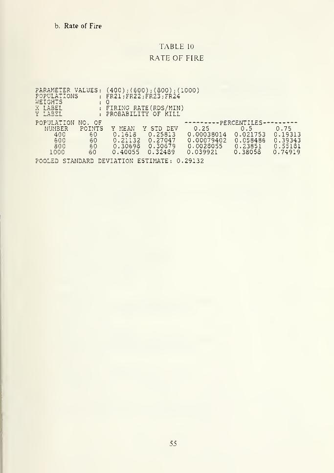
b. Rate of Fire
PARAMETER VALUESPOPULATIONSWEIGHTSX LABELY LABEL
POPULATION NO. OF
TABLE 10
R.ME OF FIRE
(400) ;(600) ;(800) ;(1000)FR21;FR22;FR23;FR24
FIRING RATE(RDS/MIN)PROBABILITY OF KILL
NUHBER POINTS Y MEAN Y STD DEV400600800
1000
60606060
0.16180.211320.306980.40055
0.258130.270470.306790.32489
0.250.000380140.000794020.00280550.039921
PERCENTILES-0.5
0.0217530.0584860.238510.38058
0.750.193130.393430.551810.74919
POOLED STANDARD DEVIATION ESTIMATE: 0.29132
55

LIST OF REFERENCES
1. Keeling. J. C. Determining Air Defense Gun Performance Using Computer
Simulations, Masters Thesis, Naval Postgraduate School. Monterey, CA, Sept
1986.
2. Ball. R. E., The Fundamentals of Aircraft Combat Survivability Analysis and
Design, AIAA Education Series, 1985.
3. NA\'ORD OP3000 Vol 2, 1st Revision, Weapon Systems Fundamentals,
Commander Naval Ordnance Systems Command, Jan 1971. I
4. McShane. E. J., Exterior Ballistics, The University of Denver Press, Denver, CO,,
1953. 'I
5. Jane's Weapon Systems 1986-1987, Jane's Publishing Inc., N Y, N Y.
56

INITIAL DISTRIBLTION LIST
No. Copies
1. Defense Technical Information Center 2
Cameron Station
Alexandria, VA 22304-6145
2. Lihrarv. Code 0142 2
Naval Postgraduate School
Monterey. CA 93943-5(H)2
3. Department Chairman. Code 67 1
Dept. of Aeronautics Engineering
Naval Postgraduate School
Monterey. CA 93943-50(h)
4. Prof Robert E. Ball. Code 67BP 2
Dept. of Aeronautics Engineering
Naval Postgraduate School
Monterey. CA 93943-5000
5. Commander 1
(Attn: Mr John Morrow, Code 33S)
Naval Weapons Center
China Lake. CA 93555-6001
6. Prof Richard D. Wood. Code 67WR 1
Dept. of Aeronautics Engineering
Naval Postgraduate School
Monterey. CA 93943-5000
7. Jung. Hyun Dae. 10
BuORD of DCNO. Headquarters of R.O.K. Na\7Singildong. "^'oungdeongpoku, Seoul 102-00
Republic of Korea
8. Director. Kim. Jung Hvva. 2
BuORD of DCNO. Headquarters of R.O.K. Navy.
Singildong. Youngdeongpoku. Seoul. 1U2-0(J
RepubUc of Korea
9. Naval Academy Library 1
Angokdong. Jinhae City. Gyungnam 602-00
Republic of Korea
10. Naval StatT Collage 1
Jehwangsandong. Jinhae City, Gyungnam 6*)2-00
Republic of Korea
57

11. Commander of N.O. A.
D
Logistic Supply Center. Hyundong.Jinhae City, Gyungnam 602-00
Republic of Korea
12. Commander of BuORD.Naval Shipyard. Hyundong.
Jmhae City, Gyungnam 002-00
Republic of Korea
13. CDR & Mrs. John C. Connell,Jr
8010 Orange Plank Dr.
Springfield, VA 22153
14. LT D. P. RoaneP.O. Box 360
Dutton. VA 23050
15. LCDR Youn. Duck Sang
SMC ?^ 1254 NTSMonterey. CA 93943
16. LCDR Shin. Dong RyongS.MC #1732 NPSMonterey. CA 93943
17. LT Sur. Joo NoSMC ^1655 NPS.Monterey. CA 93943
58


THESIS
T
J
J96225 Jung
C.l A computer study of
air defense gunc
effectiveness.
(ft i 6 6 y 1
Thesis
J96225 Jung
c.l A cotnput'='r studv of air
defense gun effective-
ness.
»5Nt/


