SHRP-C/FR-92-101 A Guide to Evaluating Thermal Effects in Concrete Pavements Per Just Andersen and Mette Elbaek Andersen G.M. Idom Consult A/S Blokken 44 DK-3460 BirkerCd,Denmark David Whiting Construction Technology Laboratories, Inc. 5420 Old Orchard Road Skokie, IL 60077 Strategic Highway Research Program National Research Council Washington, DC 1992
Transcript
SHRP-C/FR-92-101
A Guide to Evaluating Thermal Effectsin Concrete Pavements
Per Just Andersen and Mette Elbaek AndersenG.M. Idom Consult A/S
Blokken 44DK-3460 BirkerCd, Denmark
David WhitingConstruction Technology Laboratories, Inc.
5420 Old Orchard RoadSkokie, IL 60077
Strategic Highway Research ProgramNational Research Council
Washington, DC 1992
SI-IRP-C/l_.-92-101ISBN: 309-05266-1Contraa C-206
Program Manager:.Don M. HardottProjea Manager: lnam JawedProduction Editor: Marsha BarrettProgram Area Secretary:.Ann Saccomano
August 1992
key words:activation energycementcompressive strengthconcretecuing_yashfreezingheat of hydrationmaturitypavementstemperaturethermal cracking
Strategic Highway Research Program2101 Constitution Avenue N.W.Washington, DC 20418
(202) 334-3774
The pubfication of this report does not necessarily indicate approval or endorsement of the findings, opinion_.conclusions, or recommendations either inferred or specifically expr_ herein by the National Academy ofSdences, the United States Government, or the American Association of State Highway and TransportationOffidals or its member gates.
Acknowledgments
The research described herein was supported by the Strategic Highway ResearchProgram (SHRP). SHRP is a unit of the National Research Council that was authorizedby section 128 of the Surface Transportation and Uniform Relocation Assistance Act of1987.
.°°
111
Contents
Acknowledgments............ . ..................................... iii
List of Figures ................................................... vii
List of Tables .................................................... ix
2 Theoretical Background ........................................... 9Fundamentals ................................................ 9Exchange of Thermal Energy with the Environment .................... 14
3 Calculation and Evaluation of Thermal Effects .......................... 17Calculation of Temperature and Strength Development .................. 17Evaluation of Thermal Effects .................................... 18
4 Input Parameters ............................................... 21Materials ................................................... 21Concrete Mixtures ............................................. 22Climatic Conditions ........................................... 26Pavement Construction ......................................... 26The Concreting Procedure ....................................... 29The Simulation Process ......................................... 29Summary of the Input Parameters ................................. 29
5 Users' Guide .................................................. 33Description of the Table Setup ................................... 33How To Use and Interpret the Tables .............................. 34Actions To Be Taken in Case of Undesirable
Appendix: Thermal Effects Tables ....... . _............................ 43Type I Cemem ....................... ....... - .................... 45Type H Cement ................................................. 57Type HI Cement .................................................. 69Type I Cement with Class F Fly Ash ................................. 81Type H Cement with Class F Fly Ash ................................. 93
vi
List of Figures
5.1. Example of a lhermal effects table ................................. 35
vii
List of Tables
2.1. Total heat of hydration for the four clinker minerals ................... 104.1. Concrete mixtures-cement Type I ................................. 244.2. Concrete mixmres_ement Type H ................................ 244.3. Concrete mixtures-cement Type III ............................... 254.4. Concrete mixtures-cement Type I plus fly ash Class F .................. 254.5. Concrete mixtures-cement Type 1I plus fly ash Class F ................. 264.6. The properties of various base materials ............................ 274.7. Coefficients of transmission ..................................... 28
ix
Abstract
This report describes the use of tables developed tO help determine problems that mayresult from early thermal effects in concrete. The thermal behavior of concrete can beestimated from a knowledge of concrete temperature, air temperature, type of cement,and content of cement in the mixture. The thermal effects tables can be used to predictwhether too high a temperature will be reached in the pavement; whether early thermalcracking will result from large differences between the temperature of the concrete slaband the temperature of either the air or the base; or whether there is a risk of earlycracking of the concrete. Examples of the use of the tables are given along withguidelines for avoiding undesirable thermal effects.
Executive Summary
The effects of temperature and moisture early in the life of concrete strongly influence earlystrength development and long-term durability. This guide is intended to aid highwaypersonnel responsible for acceptance of concrete pavements. The guide will demonstratehow knowledge of concrete temperature, air temperature, and concrete mix characteristicsallow the user to determine whether temperature-induced problems may be expected.Guidelines for avoiding such problems are also included.
Thermal conditions, if not addressed, can lead to significant problems, including thefollowing:
• Cracking caused by large temperature differentials between the interior of theconcrete and the external environment.
• Strength loss caused by the freezing of concrete before it has reached sufficientstrength.
• Strength loss caused by high internal temperatures within the concrete mass.
To avoid such problems, the rate of heat development within the concrete as well as itsdissipation to the external environment must be known. The hydration of cement is anexothermic process, in which heat is liberated during the reaction of cement with water.The amount of heat liberated is primarily a function of the composition of the cement, thefineness of the cement, and the temperature at which hydration takes place. Cementshaving a high tricalcium silicate (C_S) content and a high fineness, such as Type III cements,generate more heat during their hydration. Cements having relatively low C_Scontent andlow fineness, such as certain Type II cements, can have relatively low heats of hydration.Pozzolonic admixtures, particularly Class F fly ashes, can be used to replace part of thecement and thereby lower the heat of hydration.
Development of heat in a concrete mass due to hydration of cement is a function of thematur/ty of the concrete. Maturity is a time/temperature function that requires a knowledgeof the activation energy of the cement being used. Activation energies for a variety ofcements were determined in this study and were used to develop relationships between heatdevelopment and maturity. Relationships between strength gain and maturity for these
cements were also determined. Maturity is normaIly expressed relative to a referencecondition. For instance, a maturity of 72 hours indicates that a particular concrete hasreached a degree of hydration (and corresponding heat development) equivalent to 72 hoursof curing at a reference temperature of 68" F (20° C).
As heat is generated within the concrete, an exchange with the external environment begins.Heat transport occurs both from the top of a paven_Lentslab into the air, and from thebottom of the slab into the base. Heat is l_ansported by thermal conduction, convection,and radiation. Thermal conduction is controlled prlm:_rilyby the thermal conductivities oilconcrete and base course and by the e_dsting temperature gradients. Convection i_controlled by the top surface convection coefficient and the difference between thetemperature of the concrete and the temperature of the air. Radiation is controlled by e.radiation constant and the surface temperature.
The balance between heat generation and heat loss is controlled by a number o1"parameters, knowledge of which allows prediction of thermal effects under a wide range o:_conditions. The parameters used in this study include type of cement (and its rate of heatdevelopment), amount of cement used per cubic yard of concrete, presence of pozzolonicadmixtures, concrete placement temperature, air temperature at placement, energies ofactivation of cement, wind velocity, pavement thickness, thermal properties of the basecourse, and the surface covering used on the pavement (if any) after finishing. To obtaina viable set of tables, the base properties, wind velocity, and thermal conductivity wereassumed at constant levels. Surface protection was assumed to be initiated 3 hours aftercuring for temperatures below 40° F (5" C).
The tables were prepared from the output of a computer simulation of heat flow andstrength development, using the parameters described above. The simulation was carriedout during the first 72 hours after placement. The following parameters must be enteredfor the tables to be used:
• Type of cementitious material.
• Content of cementJtious material.
• Concrete temperature.
• Air temperature.
• Thickness of the pavement.
4
The output of the tables consists of one of the following four symbols for any givencombination of inputs.
* = Satisfactory thermal conditions.
TD = Risk of differentials of temperature within the concrete slab that are toolarge.
EF = Risk of early freezing.
HT = Risk of temperatures within the concrete slab that are too high.
Cracking from large temperature differentials can occur when the difference exceeds 36°F (20° C). Large differentials can be minimized by reducing the temperature of theconcrete mix, reducing the amount or changing the type of cement in the mix, reducing thepavement thickness, or insulating the slab so that differential temperature is reduced. Allof these cautions (except the use of insulation) may also be applied to reducing the actualtemperature generated within the concrete. Risk of early freezing can be avoided byincreasing the temperature of the concrete, increasing the amount of cementitious materials,increasing pavement thickness, and insulating the pavement slab.
5
1
Introduction
The interaction between temperature and moisture conditions in concrete structureswithin the first few days after the concrete is cast has an important influence on thequality and durability of the concrete during its total lifespan. This means that processesoccurring in concrete at an early age can have a decisive influence on concrete qualityand durability.
This guide deals solely with the effects of temperature on concrete pavements at earlyages. The effects of moisture conditions on curing concrete are not addressed.
Unsatisfactory thermal conditions may seriously damage concrete:
• Large temperature differences may cause thermal cracking.
• The freezing of concrete before it has reached sufficient strength may causepermanent strength loss.
• Too high a concrete temperature may cause permanent strength loss.
To prevent such damage and to ensure satisfactory performance, it is necessary toaccurately plan both the concrete placement and subsequent protection procedures andto maintain a satisfactory level of control with both procedures.
The planning of concrete placement and protection procedures should include an initialcalculation and evaluation of the temperature and strength development in the concreteduring the first few days after it is cast.
Control of the concreting procedure should include the measurement and control ofthose parameters that directly influence the hardening process, e.g., the concretetemperature at placement and the air temperature. Control of the process shouldinclude on-site measurements of such properties as strength and temperature.
This guide is intended as a tool for planning the placement of concrete pavements. Itsoverall purpose is to help highway personnel evaluate the potential risk of thermal
problems. The guide does not address sucll topics as concrete mixture proportioning,paving techniques, or paving equipment.
Calculating and evaluating the temperature andstrength development of hardeningconcrete is an important aspect of concrete construction. In geometrically simpleconcrete structures, temperature and strength development can be calculated andevaluated by using existing methods based on the application of the maturity concept(Freiesleben Hansen, 1978b). These methods can be implemented in a computerprogram capable of simulating temperature and strength development as well astemperature distribution throughout geometrically simple concrete structures.
The strength of a given concrete mixture i:_a function of its age and temperature histor).The temperature history of concrete is rather complex and is influenced by manyparameters, such as composition of the concrete mixture, temperature of the concrete atthe time of placement, dimensions of the pavement, climatic conditions, and curingprocedures.
This guide contains a number of tables that can be used for preliminary evaluation ofthe potential risk of thermal problems when casting concrete pavements under specificconditions. In the tables, the type and content of cementitious material, slab thickness,air temperature, and concrete temperature at the time of placement are varied withincertain limits; whereas parameters such as wind velocity, type of base, type of surfaceprotection, and time for initiation and removal of surface protection remain constant.
The guide adheres to the following general outline:
A short introduction to the theoretical background of the simulation of temperature andstrength development in hardening concrete is given in Chapter 2. Input and outputparameters for the computer simulation program as 'well as criteria used to evaluatethermal conditions are outlined in Chapter 3. Chapter 4 contains the values of thevarious input parameters used for computer simulations. Chapter 5 is intended as ausers' guide to the thermal effects tables. Table setup and the use of the tables aredescribed, and some practical hints concerning actions to be taken in case of undesirablethermal conditions are given.
The appendix contains the thermal effects tables, which are sorted by type and contentof cementitious material. The tables can be used as described in Chapters 3, 4, and 5.These chapters also describe limitations on use of the tables. Persons interested in anintroduction to the theoretical background of the tables are advised to read Chapter 2.
8
2
Theoretical Background
The properties of concrete during its hardening are developed through the hydration process(the chemical reaction between cement and water). The hydration of portland cement leads todevelopment of heat. Depending on the conditions under which the concrete is placed andcured, the development of heat may either be beneficial or have detrimental effects.
Large temperature differences within a concrete element may cause thermal cracking, orstrength loss may result from the freezing of concrete before it has reached sufficient strength.For concrete placed under hot weather conditions, heat generation may lead to permanentstrength loss due to high concrete temperatures. To prevent such problems, knowledge of thedevelopment of concrete properties during hardening is required.
The development of concrete properties cannot be described unambiguously as a function oftime as the rate of hydration increases with temperature. This is the background for theintroduction of the maturity concept. The maturity concept makes it possible to comparedevelopment of concrete properties at different temperatures.
Maturity is defined as an equivalent age (time of hydration) at a reference temperature.
Fundamentals
The basic principles that are most important for calculation and evaluation of concrete thermaleffects are described briefly in the following sections.
Heat of Hydration
The generation of heat during the hydration process is influenced by various parameters.Some of the most important of these parameters are the following (Freiesleben Hansen1978a):
9
• Cement composition
• Cement fineness
° The temperature at which the hydration process takes place.
The heat of hydration is influenced by the content of the four clinker minerals C3S, C2S, C3A,and C4AF in the cement. The four clinker minerals have different characteristics with regardto the development of heat. At completion of hydration, the following values for the heatgeneration of the clinker minerals emerge (Table 2.1) according to Rasmussen and Andersen(1989).
b
Clinker mineral C3S C2S C3A C4AF
Heat of hydration Btu/lb 215 110 310 130
• _ i i it Ill
Table 2.1. Total heat of hydration for the four clinker minerals.*i m
• At a tenure of 73° F (23° C) for a water-to-cement (W/C) ratio of 0.45 and a Blaine fineness of 3,100 enr_/g.
The fineness of the cement affects the genera ::.on of heat. The more finely ground a cement,the more rapid is the rate of hydration, and the greater is the proportion of the cement thatreacts. A finely ground cement ads to a rapid development of heat.
The temperature at which the hyclration process takes place influences the rate of hydration.The rate of hydration increases with temperature.
The development of heat for a specific concrete mixture can be determined on the basis oflaboratory experiments such as adiabatic calorimetry.
During the hydration process, the degree of hydration ¢xis defined as the ratio between thequantity of hydrated cementitious material and the original quantity of cementitious material.The degree of hydration is a function of time, the value varying between 0 and 1. The rate ofhydration F can be expressed as the derivative of the degree of hydration with respect to time:
F= dadt
As the rate of hydration increases with temperature, the development of concrete properties i.,not unambiguously determined as a function of time. To make it possible to compare thedevelopment of concrete properties as a function of time for different temperatures, theprinciple of maturity functions is introduced, relating time and temperature to an equivalentmaturity age at a reference temperature.
10
Maturity Functions
The use of maturity functions is based on the assumption that the rate of hydration F for agiven cementitious material at a given degree of h3/dration t_ can be approximated as theproduct of a function of the degree of hydration and a functioh of the actual temperature T:
daF - - g(a)-._T) (2.1)
This assumption requires a sufficient amount of water to be available to allow the hydrationprocess to proceed unhindered throughout the entire time.
Temperature T is a function of time t during the hardening of concrete. According toequation 2.1, this gives--
da= g(a)-.gT(t))
dt
Separation of the variables and integration leads to---
f°" -1
da (2.2)g(a) dO''
The function f(T(t)) in equation 2.2 is often normalized with respect to the value of thefunction at a reference temperature To, and a new function Ho(T) is introduced:
//o(/)- .g_t))
The function Ho is called the temperature function.
If a process occurring at temperature T is compared with a process occurring at the constantreference temperature To at the same degree of hydration, the value of the function G(tz) inequation 2.2 is the same for both processes. This gives--
fo_rtO)dt= f2rat =xro).
11
The maturity Mo at the time t = x is now defined as the equivalent age xo at referencetemperature To:
As an example, a maturity of 72 hours indicates that the cementitious material has reached adegree of hydration corresponding to 72 hours of curing at the reference temperature.Several investigations to determine temperature function have been made (Freiesleben Hansen1978b; Rastmp 1955; Bergstrem 1953). It ha.+been shown (Freiesleben Hansen 1978b)through laboratory experiments that the ArrheJfius equation can be used for thermallyactivated chemical reactions as an expression :for f(T):
( g]/¢.1_ (2.3)J(/) = exp ---=-_j
where
E = an empirical energy of activation.R = the gas constant.T K = the absolute temperature.
The calculations performed in this report are based on the use of the Arrhenius model fortemperature function.
For portland cement-based systems, an empirical energy of activation has been determined asa function of the temperature in degrees Celsius (Freiesleben Hansen and Pedersen 1977):
E(T) = 33.5 kJ/mole, for T > 68 ° F (20 ° C)E(T) = 33.5 + 1.47 (20-'1") kJ/mole, for T < 68 ° F (20 ° C)
The energy of activation can be determined on the basis of laboratory experiments such aschemical shrinkage measurements.
By using the Arrhenius equation (2.3) and the reference temperature of 68° F (20°C), thetemperature function H20(T) can be calculated as--
In numerical calculations, equation 2.4 is replaced byB
- at,
where
n = the number of time intervals.
T, = the average temperature for time interval i.
The hydration period is divided into n time intervals. For each time interval, the averagetemperature T.Tais determined and the corresponding temperature function H20(.T,a-)is calculated.The maturity at any given time is equal to the summation of the contributions to the maturityduring each of the preceding time intervals.
Heat Development in Concrete
With the introduction of the maturity concept, the development of heat in concrete can bedescribed as a function of maturity. The relationship between the development of heat andthe maturity form an s-curve when plotted in a single logarithmic scale (ACI Standard 3081986). This curve can be described mathematically as---
[/_/']Q(M) -- (2." exp - (2.5)
where
Q** = the total development of heat (for M ---)**).x, = the characteristic time constant.(x = the curvature parameter.M = the maturity.
Equation 2.5 is an empirical equation. For a specific concrete mixture, the parameters Q**,x,,and (x can be calculated from experimental data for the development of heat as a function oftime Q(t) and the maturity as a function of time and temperature M(t,T). The development ofheat as a function of time is often determined on the basis of adiabatic calorimetry.
13
Strength Development in Concrete
Strength deve ,,ment in concrete is influenced by temperature development and can bedescribed with the maturity concept. Experiments have shown that the relationship betweencompressive strength and maturity form an s-curve when plotted on a single logarithmic scale(Idom 1990). Analogous to heat developmer_t, development of compressive strength can, asa good approximation, be described asm
o = a." _p - (2.6)
where
o. = the potential final strength (for M ---)**).% = the characteristic time constant.oc = the curvature parameter.M = the maturity.
Expression 2.6 is an empirical expression. The parameters o.., z,, and czcan be calculatedfrom experimental data for the development of compressive strength as a function of time(o(t)) and the maturity as a function of time and temperature (M(t,T)). The development ofcompressive strength as a function of time a(t) can be determined by testing the compressivestrength of concrete cylinders at different times.
Exchange of Thermal Energy with the Environment
Temperature development in a concrete structure is determined by the balance between heatgeneration in the concrete and heat exchange with the environment. This balance can becontrolled by variation of such parameters as the following:
• Temperature of the concrete.
• Cement type and cement content.
• Type of formwork and surface protection.
• Time at which forms are removed and time at which surface protection is initiatedand removed.
The most important mechanisms of heat exchange between concrete and environment areconduction, convection, and radiation.
14
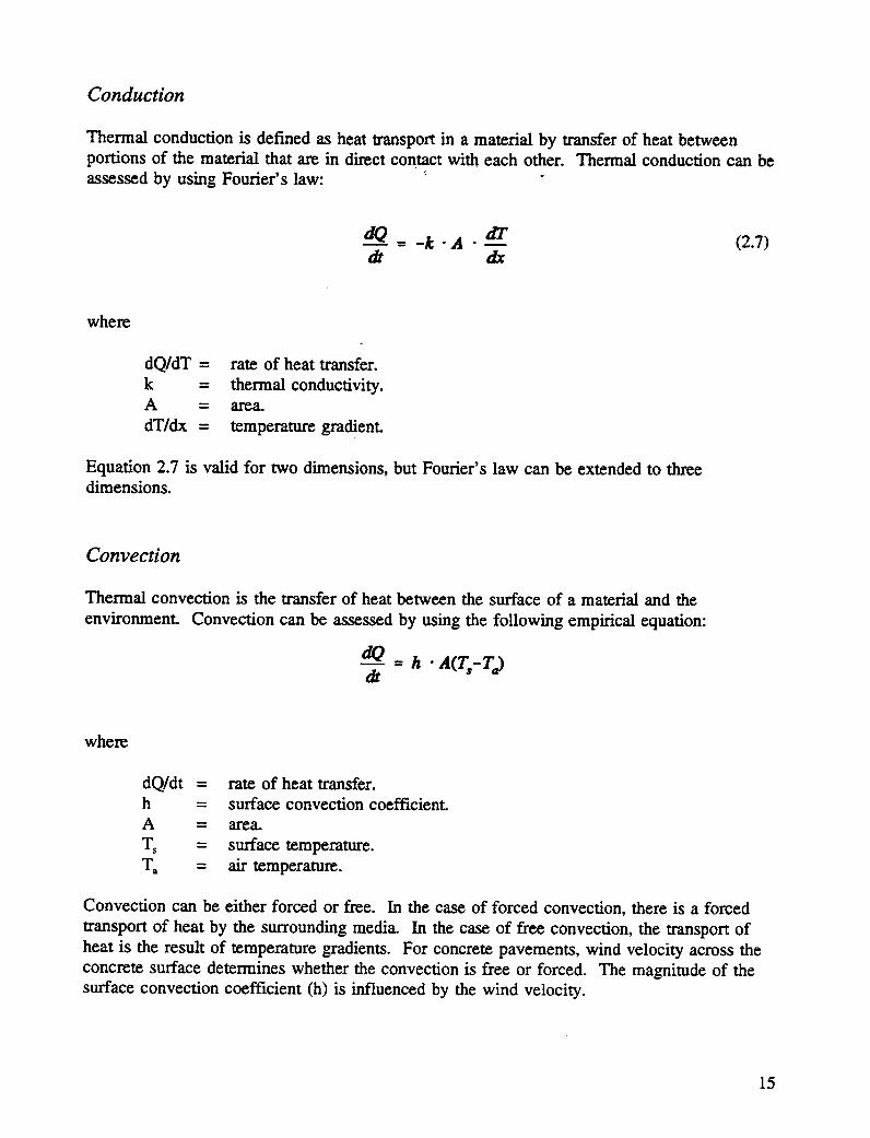
Conduction
Thermal conduction is defined as heat transport in a material by transfer of heat betweenportions of the material that are in direct contact with each other. Thermal conduction can beassessed by using Fourier's law: : "
Convection can be either forced or free. In the case of forced convection, there is a forced
transport of heat by the surrounding media. In the case of free convection, the transport ofheat is the result of temperature gradients. For concrete pavements, wind velocity across theconcrete surface determines whether the convection is free or forced. The magnitude of thesurface convection coefficient (h) is influenced by the wind velocity.
15
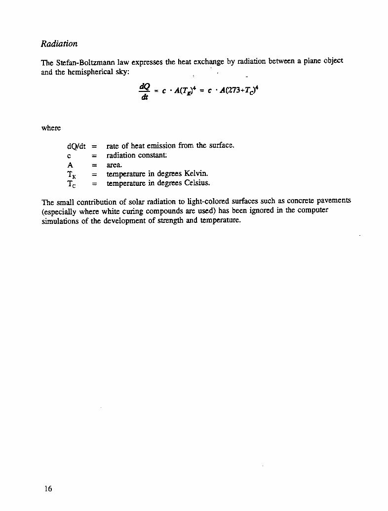
Radiation
The Stefan-Boltzmann law expresses the heat exchange by radiation between a plane objectand the hemispherical sky:
dO= c -,a(r,:_'--c •A(:z73+r_)'dt
where
dQ/dt = rate of heat emission from the surface.c = radiation constant:A = area.
TK = temperature in degrees Kelvin.Tc = temperature in degrees Celsius.
The small contribution of solar radiation to light-colored surfaces such as concrete pavements(especially where white curing compounds are used) has been ignored in the computersimulations of the development of strength and temperature.
16
3
Calculation and Evaluation of Thermal Effects
The background of the calculation and evaluation of thermal effects in concrete pavementsis described in following sections.
Calculation of Temperature and Strength Development
Temperature and strength development in geometrically simple concrete elements can becalculated with a computer simulation program. The computer program is based on theapplication of the maturity concept described in Chapter 2.
The input parameters for the program include the following:
• Types of materials.
• Specific gravity of the materials.
• Composition of the cementitious materials.
• Proportions of constituent materials.
• Concrete properties-temperature at the time of placement, slump, air content(percent by volume), water-to-cement (W/C) ratio, thermal conductivity, energyof activation, specific heat, and unit weight.
• Parameters required to mathematically describe the development of heat andcompressive strength as functions of maturity, i.e., for use in equations 2.5 and 2.6.
• Air temperature.
• Wind velocity (which affects the surface convection coefficient).
17
• Slab thickness.
• Properties of the base material-type, density, specific heat, thermal conductivity,and temperature.
• Type of surface protect/on (which affects the surface convection coefficient).
• Casting time, interval between c_stings, and number of castings.
• Time of placement and removal of the surface protection.
• Total time of simulation and time step in the calculations.
Values for a number of the input parameters are given in Chapter 4.
The output from the program consists of five graphs showing the following variables asfunctions of time:
• Temperature at the _pper surface.
• Maximum temperature within the concrete slab.
• Temperature at the bottom of the concrete slab.
• Maximum temperature difference within the slab.
• Strength of the concrete at the upper surface.
To produce an easy-to-use guide for evaluating thermal effects in concrete pavements, theoutput from the computer program has been simplified and reduced to a number of thermaleffects tables.
Evaluation of Thermal Effects
A complete _ ediction of potential thermal problem-_must include a comparison betweenthe temperar,_:e and strength development of concrete to ensure that the strength of theconcrete is at all times sufficient to resist thermal stresses. In preparing the thermal effe_:stables, however, it is considered sufficient to use the following criteria for an initialestimate:
• Evaluan'on of the risk of thermal cracking due to large temperature differences-A temperature difference of 36° F (20° C) is known from both practiadexperience and laboratory experiments to be sufficient to cause thermal cracking(Freiesleben Hansen and Pedersen 1982).
• Evaluation of the risk of damage due to freezing of concrete of imufficientstrength-ACI Standard 308 (1986) states that freezing of concrete must be
18
prevented until the concrete has developed a compressive strength of at least500 psi (approximately 5 MPa).
• Evaluation of the risk of permanent strength loss due to high concretetemperatures-Permanent strength toss can be experienced (Idorn 1990; DanishMinistry of Transport 1985) when concrete temperatures are higher thanapproximately 140° F (60° C).
In the thermal effects tables, thermal conditions are considered satisfactory if none of theabove three criteria is fulfilled. The recommendations may be conservative, but this isacceptable because the cost of removing concrete that has suffered distress due to thermaleffects is very high.
19
4
Input Parameters
To produce a handbook of a manageable size, it has been necessary to limit the range ofvalues for the input parameters needed to calculate temperature and strength development. Ithas also been necessary to keep several of the less important parameters constant and to selectappropriate limits and intervals for the remaining, more important, parameters. The inputparameters, both constants and variables, are described in the following sections.
Materials
The thermal history of hardening concrete structures is affected by the various properties ofthe materials used in the concrete.
Cementitious Materials
The thermal effects tables have been prepared for three types of cement and one type of flyash. The cement types are Type I, II, and 1TI;and the fly ash is Class F. The densities forthe materials are as follows:
• Type I cement, 3.18 gm/cm 3 (3,180 kg/m3).
• Type II cement, 3.08 gm/cm 3 (3,080 kg/m3).
• Type lIl cement, 3.18 gm/cm 3 (3,180 kg/m3).
• Class F fly ash, 2.54 gm/cm 3 (2,540 kg/m3).
Thermal effects tables have been produced for five compositions of these cementitiousmaterials: Type I cement; Type II cement; Type III cement; Type I cement containing 20%by weight of class F fly ash based on the total weight of cementitious material; and Type II
21
cement containing 20% by weight of class F ::ly ash based on the total weight of cementitiousmaterial.
Aggregates
Aggregates for the concrete mixtures are assumed to be of a quartzitic composition. Thespecific gravity for both coarse and fine aggt_gate is assumed to be 2.64. Aggregates have amaximum size of 3/8 to 2 inches (10 to 50 ram), depending on the content of cementitiousmaterial and pavement thickness.
Water
Water is assumed to be tap water, with a density of 1.00 grn/cm 3 (1,000 kg/m3).
Concrete Mixtures
For each of the five cementitious systems, ten different concrete mixtures are included in thetables. Each mixture corresponds to a specific content of the cementitious material. Thecontent of cementitious material varies between 525 and 750 lbsdyd 3 (311 and 445 kg/m 3) insteps of 25 lbs/yd 3 (15 kg/m3). All concrete mixtures axe assumed to be air entrainedaccording to ACI Standard 211.1 (1986).
For the concrete mixtures, the following parameters were used:
• The estimated compressive strength was varied between 4,300 and 5,400 psi (30and 37 MPa), depending on the composition of the concrete mixture (the strength isestimated by Feret's [1982] formula).
• An air content of 5-7.5% by volume (following ACI recommendations for severeenvironments).
• A slump of 2 or 3 inches (50 or 75 ram).
• A W/C ratio of 0.45.
The composition of the various concrete mixtures is shown in Tables 4.1-4.5.
ACI Guide 305 (1986) recommends that the concrete temperature be maintained below100 ° F (38 ° C), and ACI Standard 308 (1986) recommends that the concrete temperature bemaintained above 50° F (10° C). The upper and lower limits for the placement temperatureof the concrete are therefore set at 50° and ;i00° F (10° and 38 ° C), and the temperature isincreased in steps of 10° F (6° C).
22
The thermal conductivity of the concrete mixtures is assumed to be 1.3 Btu/ft.h .o F(8.1 kJ/m-h -° C).
The values of the energy of activation used for the computer simulations were determinedexperimentally. The energies of activation obtained were as follows:
• Type I cement, E = 46.2 Btu/mole (48.8 kJ/mole).
• Type II cement, E = 39.1 Btu/mole (41.3 kJ/mole).
• Type III cement, E = 40.3 Btu/mole (42.5 kJ/mole).
• Type I cement with fly ash, E = 36.2 Btu/mole (38.2 kJ/mole).
• Type II cement with fly ash, E = 34.9 Btu/mole (36.8 kJ/mole).
The parameters describing the development of heat according to equation 2.5 were alsodetermined experimentally on the basis of adiabatic calorimetry. For the calculation of theparameters, the experimentally determined energies of activation were used. The parametersdescribing the development of heat are as follows:
• Type I cement, Q**= 139.2 Btu/Ib cement (323.4 kJ/kg cement)xe = 13.55 ha = 1.03
• Type II cement, Q**= 134.9 Btu/lb cement (313.5 kJ/kg cement)1:_ = 15.20ha = 0.95
• Type m cement, Q**= 154.4 Btu/lb cement (358.8 kJ/kg cement)"c_ = 8.26 hcz = 0.99
• Type I cement with fly ash, Q**= 165.1 Btu/lb cement (383.6 kJ/kg cement)"c_ = 13.66 hcz = 1.08
• Type IT cement with fly ash, Q,. = 160.1 Btu/lb cement (372.0 kJ/kg cement)"c, = 20.69 ha =0.94
The parameters describing the development of strength according to equation 2.6 have notbeen determined experimentally, but have been approximated. For each concrete mixture, thevalue of _**was approximated by the estimated compressive strength given in Tables 4.1--4.5.The values of the parameters "c_and _ were approximated by the values of the parametersdetermined for the development of heat.
Max. aggregate size (inches¢) 2 lZ/: llh 1 3/, 1/: sh 3h ih sh
Slump (inches) 2 2 2 2 2 2 2 3 3 3
| |1
Table 4.5. Concrete mixtures cement Type II plus fly ash Class F.ii m
*Ikg/m3-- 1.685lb/yd3?IMPa= 145.0_i$1mm= 0.0394in
Climatic Conditions
Climatic conditions such as air temperature and wind velocity influence temperaturedevelopment in concrete pavements during hardening.
Air Temperature
Air temperature is varied within the interval from 0° to 100° F (-18 ° to 38° C) in steps of20° F (11° C).
Wind Velocity
The velocity of the wind across a newly cast crete surface influences the rate of heattransfer from the surface to the air. An incre.: in wind velocity increases the heat loss fromthe surface. The ASHRAE Handbook (1989) recommends wind velocities of 15 mph (7 m/s)in the winter and 7.5 mph (3 m/s) in the summer. In the computer simulations of thetemperature and strength development in the hardening concre_::,the average wind velocity wasmaintained at 11 mph (5 m/s).
Pavement Construction
Temperature development in a newly cast concrete pavement is, among other parameters,influenced by the structure of the pavement and the construction practices applied.
26
Temperature development is affected by factors such as the thickness of the pavement, thecondition of the pavement base, and the methods used to protect the pavement surface.
Dimensions of the Pavement
The pavement is assumed to be a plate of infinite width and length. The only dimensionaffecting temperature development is the thickness of the pavement. The thermal effects tablesinclude the following slab thicknesses: 8, 12, 16, and 20 inches (0.2, 0.3, 0.4, and 0.5 m).
Condition of the Base
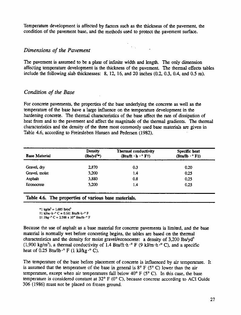
For concrete pavements, the properties of the base underlying the concrete as well as thetemperature of the base have a large influence on the temperature development in thehardening concrete. The thermal characteristics of the base affect the rate of dissipation ofheat from and to the pavement and affect the magnitude of the thermal gradients. The thermalcharacteristics and the density of the three most commonly used base materials are given inTable 4.6, according to Freiesleben Hansen and Pedersen (1982).
Density Thermalconductivity SpecificheatBase Material (Ibs/yd3.) (Btu/ft•h •° Ft) (Btu/Ib•° F_:)
Table 4.6. The properties of various base materials.
*1 kg/m3= 1.685 lb/yd_?1 kJ/m-h.o C = 0.161 Btu/ft-h-° F_:1J/kg-0 C = 2.388 x 10⁴ Btu/lb-0 F
Because the use of asphalt as a base material for concrete pavements is l,imited, and the basematerial is normally wet before concreting begins, the tables are based on the thermalcharacteristics and the density for moist gravel/econocrete: a density of 3,200 lbs/yd 3(1,900 kg/m3), a thermal conductivity of 1.4 Btu/ft-h .° F (9 kJ/m-h -° C), and a specificheat of 0.25 Btuflb .o F (1 kJ/kg .o C).
The temperature of the base before placement of concrete is influenced by air temperature. Itis assumed that the temperature of the base in general is 8° F (5° C) lower than the airtemperature, except when air temperatures fall below 40 ° F (5 ° C). In this case, the basetemperature is considered constant at 32° F (0 ° C), because concrete according to ACI Guide306 (1986) must not be placed on frozen ground.
27
Surface Protection
To minimize evaporation from the surface of a newly placed concrete pavement, the surface isusually covered with a curing compound or plastic sheeting after the pavement is finished.During winter construction, a surface protectic,n with sufficient-insulating properties is used toprevent damage due to early freezing of concrete of insufficient strength.
The insulating properties of the surface cover affect the rate of heat transfer from the newlycast concrete to the air. The coefficient of traasmission expresses the transmission of energy
per unit area per hour per degree. The coefficient of transmission thus depends on theinsulating properties of the surface cover and 'the surface convective coefficient of transmission_, which is a function of the wind velocity across the surface of the pavement. (See sectionabove entitled "Wind Velocity" for the wind velocity used for computer simulations.)
In the calculations, it is assumed that the concrete pavement is covered with wet burlap, white
curing compound, wet cotton, or polyethylene film, except in air temperatures below 400 F(5° C). If the air temperature is below 40 ° F (5° C), the pavement is assumed to be coveredwith 2 inches (50 ram) of straw or another insulating material. The coefficients oftransmission for the chosen wind velocity and surface coverings (Freiesleben Hansen andPedersen 1982) follow in Table 4.7.
I
Coefficient of transmission
Type of surface cover Wind velo(_ty (mph*) (Btu/ft _-h .o Ft)
No cover 11 Approx. 90
Wet burlap, polyethylene fdm, white curing 11 Approx. 60compound, or wet cotton
Straw (2 inches) or other insu!arng material I 1 Approx. 5
Table 4.7.. Coefficients of transmission.lira
*1 m/s =2.24 mphtl kJImZ'h"°C = 4.896x lff=Btu/ft=-h-*F
The protection of the pavement surface is assumed to be initiated 3 hours after casting. If theair temperature is below 40" F (5° C) and an insulating material is used, the insulation isassumed to be removed 24 hours after casting. For the remaining curing period, the pavementis assumed to be covered with wet burlap, polyethylene fi.lm, white curing compound, or wetcotton.
28
The Concreting Procedure
The following assumptions have been made for the concreting procedure:
• Casting time is 2 hours. "
• Concrete is placed in one layer.
The Simulation Process
Temperature and strength development are calculated over an elapsed time of 72 hours. Thetime step in the calculations is 1 hour.
Summary of the Input Parameters
A summary of all the input parameters for the computer simulations follows.
Materials
The materials are as follows:
• Cement Types I, II, and 111.
• Class F fly ash.
• Aggregate of a quartzitic composition.
• Water.
The specific gravities for the materials are as follows:
• Type I cement, 3.18 gm/cm 3 (3,180 kg/m3).
• Type II cement, 3.08 gm/cm 3 (3,080 kg/m3).
• Type 1TIcement, 3.18 grodcm3 (3,180 kg/m3).
• Class F fly ash, 2.54 gm/cm 3 (2,540 kg/m3).
• Aggregate, 2.64 gm/cm 3 (2,640 kg/m3).
• Water, 1.00 gm/cm 3 (1,000 kg/m3).
29
In percentage by weight of the total weight of cementitiou_ material, the five compositions ofthe cementitious material are as follows:
• Type I cement, 100%.
• Type 11 cement, 100%.
• Type III cement, 100%.
• Type I cement, 80% plus Class F fly ash, 20%.
• Type II cement, 80% plus Class F fly ash, 20%.
Concrete Mixtures
The composition of the various mixtures are shown in Tables 4.1--4.5.
The concrete pouring temperatures are 50°, 60°, 70 °, 80 °, 90°, or 100 ° F (10 °, 16°, 21 °, 27°,32°, or 38° C) in the tables.
The slump is 2 or 3 inches (50 or 75 ram), the air content ranges from 5 to 7.5%, and the W/Cratio is 0.45.
The thermal conductivity is 1.3 Btu/ft'h "° F (8.1 El/m "h"° C) for all concrete mixtures.
The specific heat and unit weight for all concrete mixtures are calculated by the program.
The energies of activation are as follows:
• Type I cement, E = 46.2 Btu/mole (48.8 kJ/mole).
• Type II cement, E = 39.1 Btu/mole (41.3 kJ/mole).
• Type 11"Icement, E = 40.3 Btu/mole (42.5 El/mole).
• Type I cement with fly ash, E = 36.2 Btu/mole (38.2 El/mole).
• Type II cement with fly ash, E = 34.9 Btu/mole (36.8 El/mole).
The parameters describing the development of heat according to equation 2.5 are as follows:
• Type I cement, Q**= 139.2 Btu/lb cement (322;.4 kJ/kg cement)xe = 13.55 ho_ = 1.03
30
• Type II cement, Q**= 134.9 Btu/lb cement (313.5 kJ/kg cement)x, = 15.20 ho_ = 0.95
• Type III cement, Q**= 154.4 Btu/lb cement (358.8 _kJ/kgcement)xo = 8.26 htt = 0.99
• Type I cement with fly ash, Q**= 165.1 Btuflb cement (383.6 kJ/kg cement)% = 13.66 htz = 1.08
• Type 11 cement with fly ash, Q.. = 160.1 Btu/lb cement (372.0 kJ/kg cement)x_ = 20.69 hot = 0.94
Strength development is described with the same values used for x, and tz as were used forheat development. For each concrete mixture, o**is approximated by the estimated value forthe compressive strength given in Tables 4.1--4.5.
Climatic Conditions
The thermal effects tables include the following air temperatures: 20 °, 40 °, 60°, 80°, or 100° F(-18 °, -7 °, 4 °, 16°, 27 °, or 38 ° C).
The wind velocity is assumed to be 11 mph (5 m/s) in all cases.
Pavement Construction
The tables include the following slab thicknesses: 8, 12, 16, or 20 inches (0.2, 0.3, 0.4, or0.5 m).
The base is assumed to be of a quartzitic composition, and the density of the base material is3,200 lbs/yd 3 (1,900 kg/m3).
The specific heat of the base is 0.25 Btuflb-° F (1 kJ/kg .o C) and the thermal conductivity is1.4 Btu/ft-h .o F (9 kJ/m "h.o C).
The three different types of surface covers leading to the following coefficients of transmissionfor the chosen wind velocity were given in Table 4.7, i.e., 90 Btu/ft2-h .o F(1,838 kJ/m 2"h .o C) for no cover; 60 Btu/ft2"h .o F (1,225 kJ/m2-h .o C) for wet burlap,polyethylene film, white curing compound, or wet cotton; and 5 Btu/_-h .o F(102 kJ/m2-h .o C) for 2 inches (50 mm) of straw or other insulating material.
31
Concreting Procedure
The casting time is 2 hours, and the concrete is placed in one layer.
The surface protection is assumedto be initiatJ:d3 hours_ff_erconcrete is cast.
If the temperaturefalls below 40° F (5° C) and an insulating surface protection is usgd, it isassumed that the insulating protection is removed 24 hours after casting and is replaced withwet burlap, polyethylene film, white curing compound, or wet cotton.
The Simulation Process
The total simulation time is 72 hours, and the time step in the calculations is 1 hour.
32
5
Users' Guide
This chapter gives instructions for the use of the thermal effects tables. Persons interested in
information regarding the theoretical background for the tables are advised to read Chapter 2.A short description of the calculation and evaluation of the curing processes is given inChapter 3, and the input parameters for the computer simulations are outlined in Chapter 4.
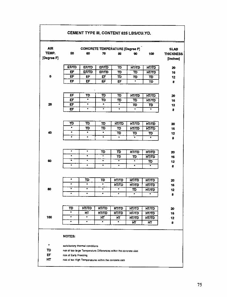
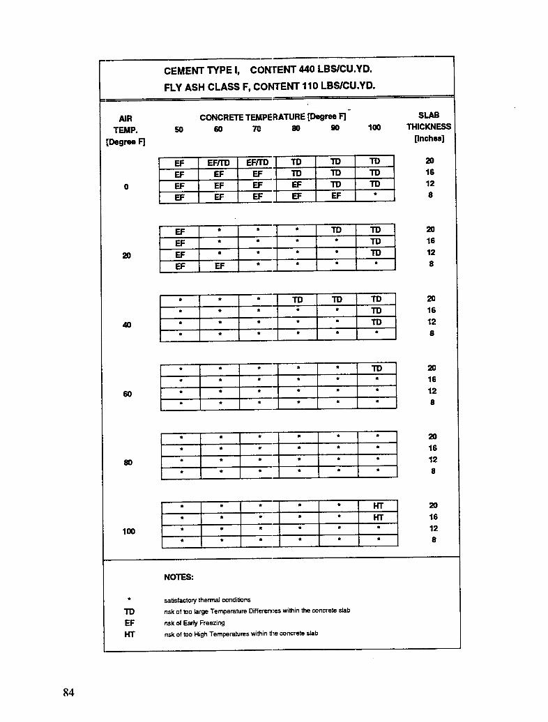
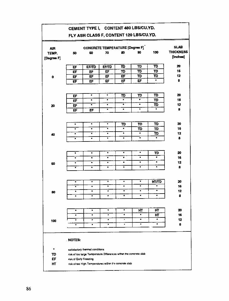
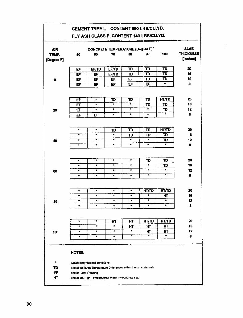
Description of the Table Setup
Tables axe prepared by using the output from a computer simulation of temperature andstrength development in the concrete pavement in the first 72 hours after it is placed.
For each composition of the cementitious material and for each of the ten different concretemixtures (characterized by the content of cementitious material), 144 simulations oftemperature and strength development have been performed varying air temperature, concretetemperature, and slab thickness. The simulated temperature and strength developments havebeen (1) evaluated according to the three criteria described in the section of Chapter 3 entitled"Evaluation of Thermal Effects" and (2) organized into the thermal effects tables.
The following data are entered into the tables:
• Type of cementitious material----Cement Type I, Type 1/, Type HI, Type I containing20% by weight Class F fly ash based on the total weight of cementitious material, orType II containing 20% by weight Class F fly ash based on the total weight ofcementitious material.
• Total content of cementitious material--For each of ten concrete mixtures, the totalcontent of cementitious materials are 525, 550, 575, 600, 625, 650, 675, 700, 725, or750 lbs/yd 3 (311, 326, 341, 356, 371,386, 400, 415, 430, or 445 kg/m3).
• Air temperature---0 °, 20°, 40°, 60°, 80°, or 100° F (-18 °, -7 °, 4 °, 16°, 27°, or38° C).
• Pavement thickness---8, 12, 16, or 20 inches (0.2, 0.3, 0.4, or 0.5 m).
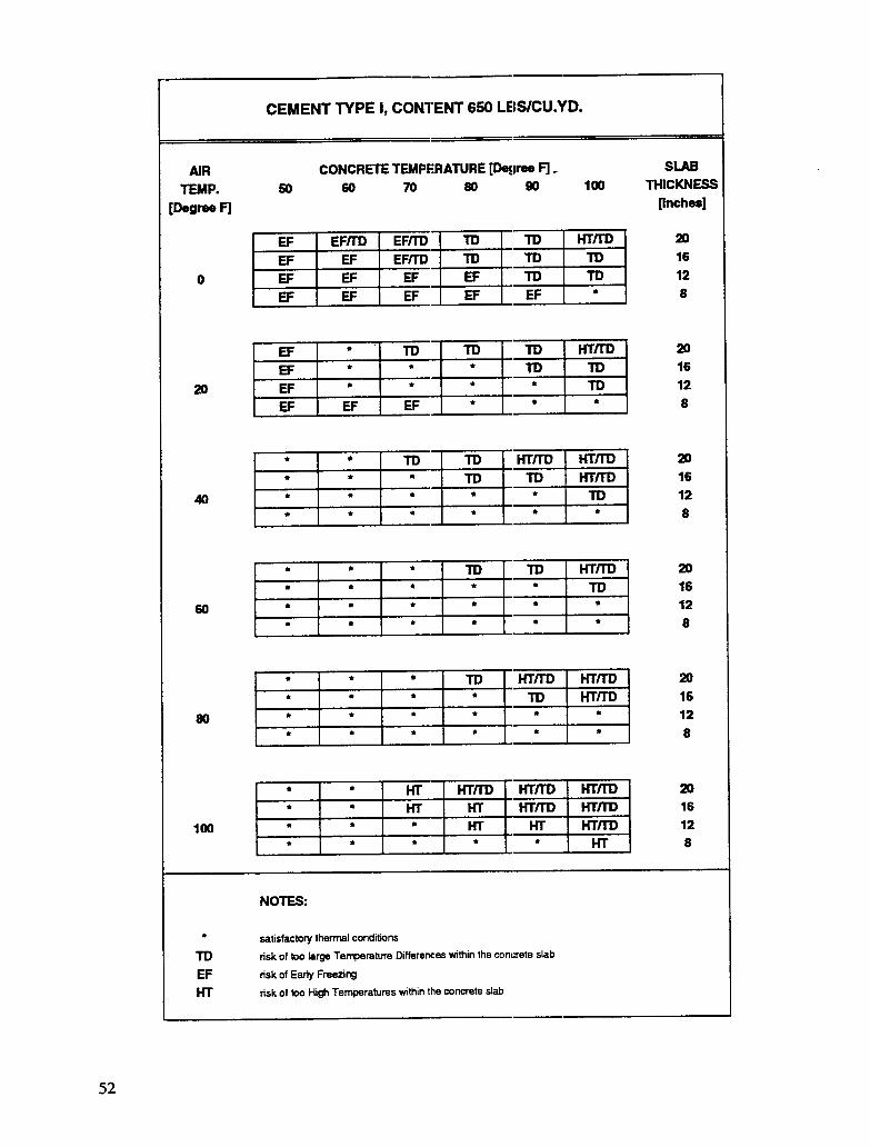
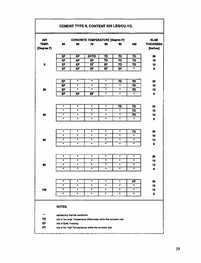
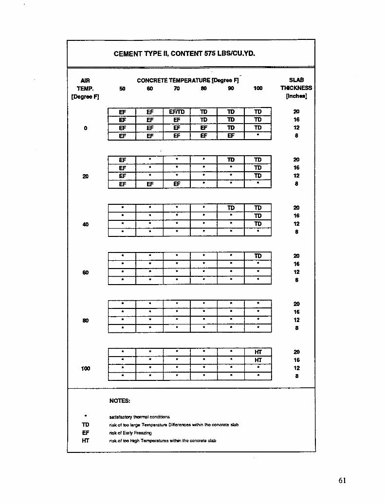
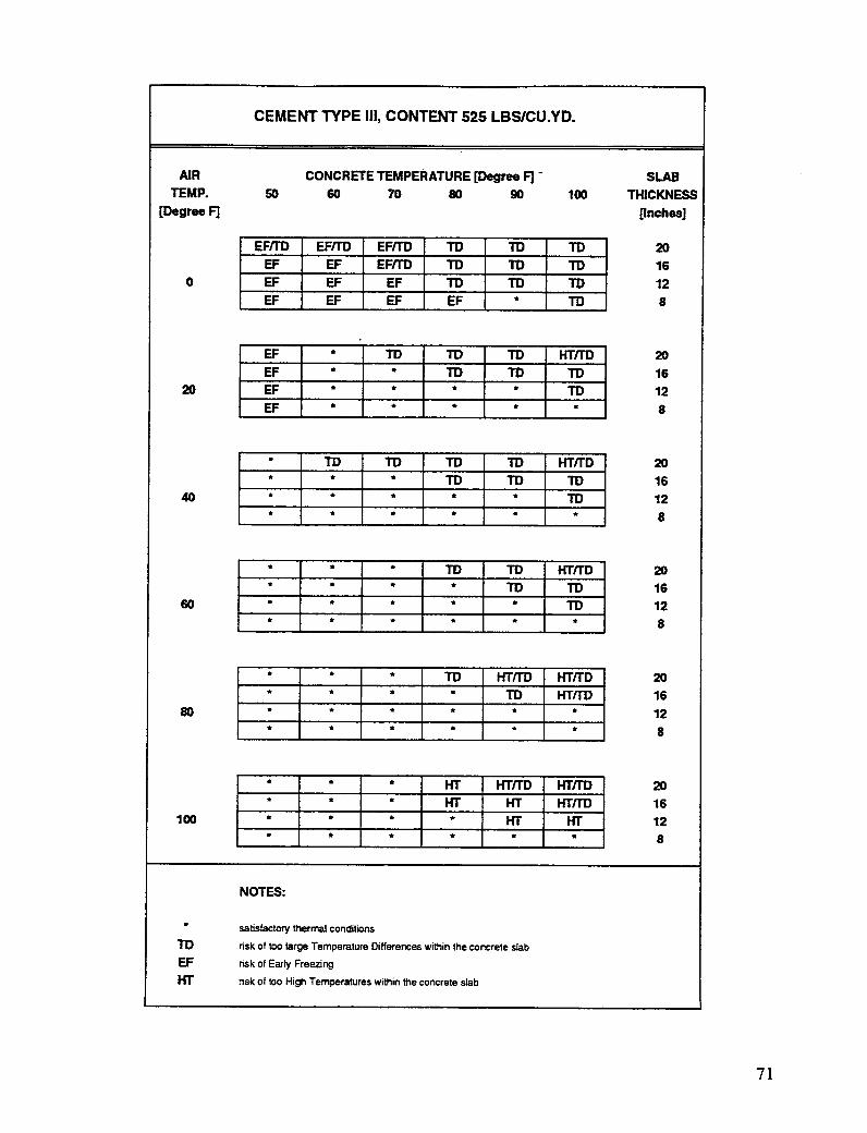
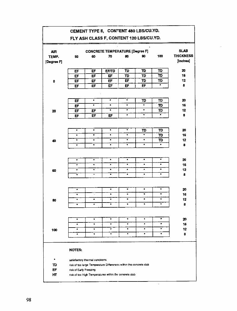
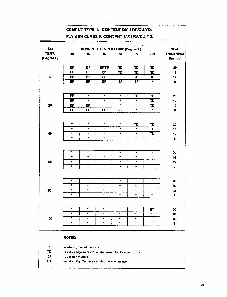
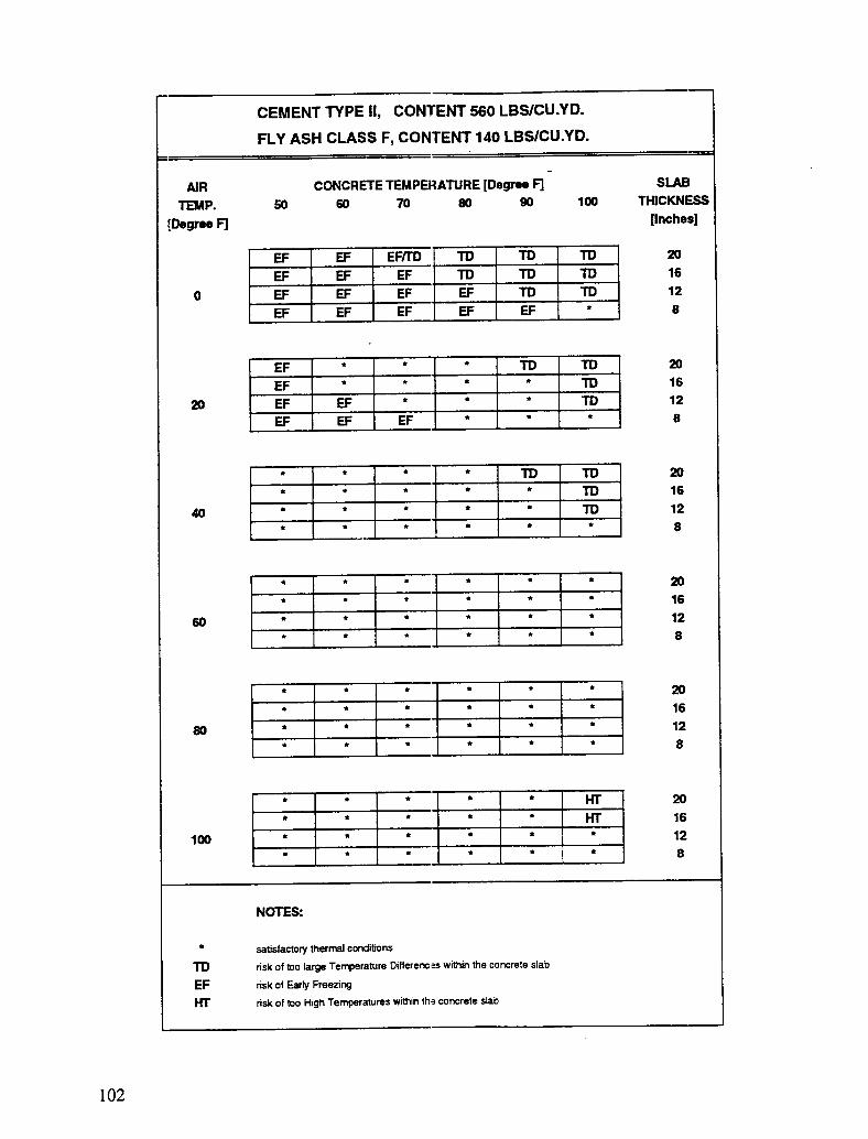
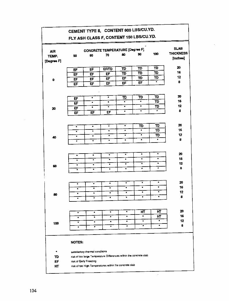
Output from the tables consists of one of the following four symbols:
* = Satisfactory thermal conditions."I'D = Risk of differentials of temperature wi_n the concrete slab that are too
large.EF = Risk of early freezing.ITF = Risk of temperatures within the concrete slab that are too high.
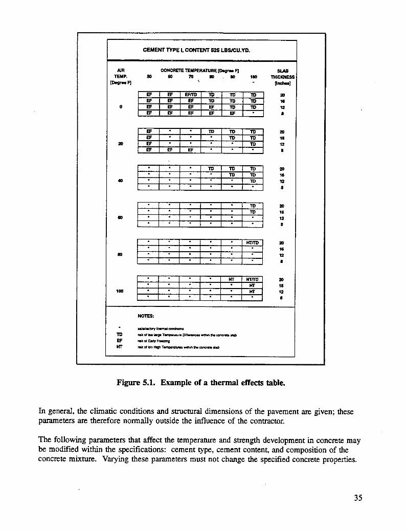
In the thermal effects tables, satisfactory cond'_tions are def'med as conditions that do not causeany of these three to be encountered. An example of a table is shown in Figure 5.1.
For each table, a major heading states the type and content of cementitious material used. Thetype and content of cementitious material refers directly to one of the compositions of concretemixtures shown in Tables 4.1--4.5.
A horizontal axis at the top of each table shows the cont=ete temperature (in degreesFahrenheit) at the-time of placement.
The expected average air temperature (in degrees Fahrenhei0 during the fLrst 72 hours afterplacement is shown in a vertical row of numbers to the left in the tables; the slab thickness (ininches) is given in a vertical row of numbers to the right.
For a given average air temperature, a horizontal table consisting of six columns and four rowsis shown. Each of the columns represents a specific concrete temperature at the time ofplacement, and each row represents a specific slab thickr_ess. The content of the tables is oneof four symbols. These symbols are the output from the tables. An explanation of thesymbols is given in table footnotes.
How To Use and Interpret the Tables
It is important to realize that these tables represent computer simulations of temperature andstrength development in hardening concrete and are only a guide for the planning of concretingand curing procedures. The tables in this guide are intended to help in preliminary evaluation.,.of the ther-: .,.1conditions for hardening concrete pavements.
34
CEMENT TYPE I, CONTENT 525 LBS/CU.YD.
NR CONCRETE TEMPERATURE [Degr_ F] SLABTEMP. SO 20 70 10 20 100 THICKNESS
In general, the climatic conditions and structural dimensions of the pavement are given; theseparameters are therefore normally outside the influence of the contractor.
The following parameters that affect the temperature and strength development in concrete maybe modified within the specifications: cement type, cement content, and composition of theconcrete mixture. Varying these parameters must not change the specified concrete properties.
35
A contractor must often vary the following parameters to achieve the optimum properties ofconcrete for a given job:
• Extent of insulation (surface proteclion).
• Concrete temperature at the time of 'placement.
• Time for removal of the surface px,tection.
The thermal effects tables provide information on the type of cementitious materials, thecontent of cementitious materials, the air temperature, and the slab thickness. In this case, thecontractor need only determine a safe concre_: temperature at the time of placement.
Use of the tables is illustrated by the following three examples.
First it is planned to cast a concrete pavement with a thickness of 16 inches (0.4 m) in a hotperiod of the summer. The concrete contains 650 lbs/yd _"(386 kg/m 3) Type I cement. Theexpected average air temperature during the first 72 hours after casting is 100° F (38 ° C).What would a suitable concrete placement temperature be?
From the thermal effects table for Type I cement and a cement content of 650 lbs/yd 3(386 kg/m3), it is found that an average air temperature of 100° F (38 ° C) and a pavementthickness of 16 inches (0.4 m) will be satisfactory for a concrete pouring temperature of 50° or60 ° F (10 ° or 16° C). For concrete temperatures higher 'than 60° F (16° C), there is a risk ofconcrete temperatures being too high or thermal differences being too large.
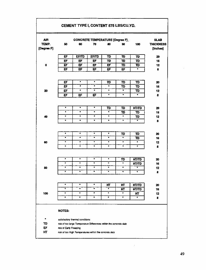
Next, it is planned to cast a concrete pavement with a slab thickness of 8 inches (0.2 m) duringthe winter. The concrete contains 575 lbs/yd 3 (341 kg/m 3) Type HI cement. The concretetemperature at the time of placement is to be 50° F (10 ° C), and the expected average airtemperature for a period of 72 hours is 40 ° F (4° C). It is planned to cover the concretesurface with 2 inches (50 mm) of insulating material in the period from 3 to 24 hours aftercasting. Shortly before casting, the weather conditions clhange--the expected average airtemperature is now 20 ° F (-7 ° C). What effect will this have on the thermal conditions for thepavement?
From the table for Type HI cement and a cement content: of 575 lbs/yd 3 (341 kg/m3), it isfound that an average air temperature of 40 ° IF(4 ° C), a slab thickness of 8 inches (0.2 m), an,5a concrete placement temperature of 50° F (10 ° C) are satisfactory. With a change of theaverage air temperature to 20° F (-7 ° C), there is a risk of early freezing of the concrete. Theconcrete placement temperature must therefore be raised to 60° F (16 ° C) by using heatedmixing water or aggregates.
Finally, four experimental sections of a concrete pavement have been planned. The foursections have four different slab thicknesses: 20, 16, 12, and 8 inches (0.5, 0.4, 0.3, and0.2 m). The concrete for the four sections contains 600 Ibs/yd3 (356 kg/m 3) Type I cement and150 lbs/yd 3 (89 kg/m -_)Class F fly ash. The concrete temperature at the time of placement is
36
90 ° F (32 ° C), and the expected average air temperature for the first 72 hours after casting is60 ° F (16 ° C). Will satisfactory thermal conditions exist for all four pavement sections?
From the table for Type I cement with fly ash, a cement content of 600 lbs/yd 3 (356 kg/m3),and a content of Class F fly ash of 150 lbs/yd 3 (89 k_m3), it is found that an average airtemperature of 60° F (16 ° C) and a concrete placement temperature of 90° F (32 ° C) willprovide satisfactory thermal conditions only for slab thicknesses of 16, 12, and 8 inches (0.4,0.3, and 0.2 m). For a slab thickness of 20 inches (0.5 m), there is a risk of temperaturedifferences being too large. The concrete pouring temperature should be reduced to 80° F(27 ° C) or below to avoid potential problems.
If the thermal effects tables indicate a risk of damage to the concrete (TG, HT, EF), it may benecessary to take precautions to avoid problems.
Actions To Be Taken in Case of Undesirable Thermal Conditions
If predictions made during the planning of the concreting procedure show that the thermalconditions are undesirable, then actions must be taken to achieve satisfactory results. In thissection, some practical hints are given as examples of such actions to be taken. It should bepointed out that all actions must be taken under consideration of fulfillment of thespecifications for a given job; it is outside the purpose of this guide to estimate the economicalconsequences of the suggested actions.
The risk of temperature differences being too large within the concrete slab may be reducedby--
• Reducing the concrete placement temperature.
• Insulating the concrete slab immediately after casting and finishing.
• Reducing the content of the cementitious materials.
• Choosing a cement type with a lower heat of hydration.
• Raising the temperature of the surroundings (e.g., using heat-vented tents).
It should be pointed out that the effects of the second action described above cannot beinvestigated through use of this guide. As stated earlier, the time before insulating the concretesurface remains constant in all the tables. If the concrete slab is to be insulated immediatelyafter casting and finishing, it will be necessary to perform a temperature and strengthcalculation based on actual conditions.
37
The risk of damage due to early freezing may be reduced by--
• Increasing the concrete placement temperature.
• Insulating the concrete slab immedi_itely after casting and finishing.
• Lengthening the period of insulatiort of the concrete surface.
• Increasing the content of cementitious materials.
• Choosing a cement type with a higher heat of hydration.
• Raising the temperature of the surrc,undings (e.g., using heat-vented tents).
It should be pointed out that the effects of the second anti third actions listed above cannot beinvestigated through use of this guide. The time for initiation and removal of the insulation ofthe concrete surface remains constant in all the tables. If the concrete slab is to be insulated
for a longer period of time, it will be necessm_j to perform a temperature and strengthcalculation based on actual conditions.
The risk of temperatures becoming too high within a concrete slab may be reduced by--
• Reducing the concrete placement temperature.
• Reducing the content of cementitious materials.
• Choosing a cement type with a lower heat of hydration.
• Reducing the temperature of the stu'roundings (e.g., shading).
The effects of some of the actions mentioned above are illustrated by the following examples.
First, a concrete pavement with a thickness of 20 inches (0.5 m) is planned to be cast duringwinter. The expected average air temperature is 40 ° F (4° C). The concrete contains 600lbs/yd 3 (356 kg/m 3) Type II cement, and the concrete terttperature at the time of placement is80° F (27 ° C). The concrete surface is covered with 2 inches (50 ram) of insulating materialin the period from 3 to 24 hours after casting The tables indicate that, under these conditions,a risk of too large temperature differences within the concrete slab exists. The followingactions can be taken to provide satisfactory thermal conditions.
• Concrete placement temperature can be decreased to 70 ° F (21° C).
• Cement content can be reduced to 575 lbs/yd 3 (341 kg/m3).
• Temperature of the surroundings can be raised to 60° F (16° C).
38
Second, it has been planned to cast a concrete pavement with a thickness of 12 inches (0.3 m)during the winter. The expected average air temperature for the period is 20° F (-7 ° C). Theconcrete contains 580 Ibs/yd 3 (344 kg/m 3) Type II cement and 145 lbs/yd 3 (86 kg/m 3) Class Ffly ash. The concrete temperature is 60° F (16° C) at the time of placement. The concretesurface is covered with 2 inches (50 ram) of insulating material in the period from 3 to 24hours after casting. Under these conditions, earlY freezing of the concrete may take place.The following actions can be taken to provide satisfactory thermal conditions.
• Concrete placement temperature can be increased to 70° F (21° C).
• Cement content can be increased to 600 lbs/yd 3 (356 kg/m3), and fly ash content canbe increased to 150 lbs/yd 3 (89 kg/m3).
• The cement can be changed to Type I.
• The temperature of the surroundings can be increased to 40 ° F (4° C).
Finally, it is planned to cast a concrete pavement with a thickness of 20 inches (0.5 m) duringa summer period with an average air temperature of 100° F (38 ° C). The concrete contains600 lbs/yd 3 (356 kg/m 3) Type 111cement, and the concrete pouring temperature is 60° F(16° C). Under these conditions, a risk of too high temperatures within the concrete slabexists. The following actions can be taken to provide satisfactory thermal conditions.
° Concrete placement temperature can be reduced to 50° F (10° C).
• Cement content can be reduced to 575 lbs/yd 3 (341 kg/m3).
• The cement can be changed to Type I or Type 11.
• The temperature of the surroundings can be changed to 80 ° F (27 ° C).
39
References
ACI Guide 306. 1986. Cold weather concreting. ACI manual of concrete practice. Part 2.Detroit: American Concrete Institute.
ACI Guide 305. 1986. Hot weather concreting. ACI manual of concrete practice. Part 2.Detroit: American Concrete Institute.
ACI Standard 308. 1986. Standard practice for curing concrete. ACI manual of concretepractice. Part 2. Detroit: American Concrete Institute.
ACI Standard 211.1. 1986. Standard practice for selecting proportions for normal,heavyweight, and mass concrete. ACI manual of concrete practice. Part 1. Detroit:American Concrete Institute.
ASHRAE Handbook. 1989. Fundamentals: I-P edition. Atlanta: American Society ofHeating, Refrigeration, and Air Conditioning Engineers, Inc.
Bergstr_rn, S. G. 1953. Curing temperature, age and strength of concrete. Magazine ofConcrete Research 5 (14).
The Danish Ministry of Transport. 1985. The concrete of the Far_ Bridges.
Feret, R. 1982. On the compaction of hydraulic cement mortars. Annales des Ponts etChaussees 4 (21), Memoires Serie 7e, Paris.
Freiesleben Hansen, P. 1978a. Heerdeteknologi - 1 Portlandcement (in Danish). AalborgPortland og BKF-certtralen.
Freiesleben Hansen, P. 1978b. Heerdeteknologi- 2 Dekrementmetoden (in Danish). AalborgPortland og BKF-centralen.
Freiesleben Hansen, P., and E. J. Pedersen. 1977. Mfileinstrument til kontrol af betonsheerdrdng(in Danish). Nordisk Betonb No. 1.
Freiesleben Hansen, P., and E. J. Pedersen. 1982. SBI-Anvisning 125 Vinterst_bning afbeton (in Danish). BIG and SBI.
41
Idorn, G. M. 1990. Concrete curing technology. _ Bu//et/n, No. 19.
Rasmussen, T. H., and T. Andersen. 1989. Haerdeteknologi (in Danish). Beton-TeknilgJune 15, CtO.
Rastrup, E. 1955. Heat of hydration in cono'ete. Magaz/ne of Concrete Research 7 (20).
42
Appendix
Thermal Effects Tables
This appendix contains the thermal effects tables for the report titled "A Guide toEvaluating Thermal Effects in Concrete Pavements." The guide was prepared for theStrategic Highway Research Program C206 by G.M. Idorn Consult A/S.
A users' guide to the thermal effects tables is included in Chapter 5 of the main report.The guide describes the limitations of the tables, table setup, how to use the tables, andwhat actions should be taken if undesirable thermal conditions are encountered. Themain report also contains an introduction to the theoretical background for the tables(Chapter 2).
The thermal effects tables are divided into five groups that correspond to thecementitious systems used. The tables are arranged according to content ofcementitious material.
43
Type I Cement
45
CEMENT TYPE I, CONTENT 525 LBSICU.YD.
AIR CONCRETE TEMPERATURE [Degree F] _ SLABTEMP. 50 60 70 80 90 100 THICKNESS