25
A High-Performance Portable Audio Amplifier Rowan University James K Beard, Ph.D. [email protected] [email protected] June 11, 2007
| Date post: | 13-Jul-2018 |
| Category: |
Documents |
| Upload: | truongminh |
| View: | 224 times |
| Download: | 3 times |
A High-Performance Portable Audio Amplifier
Rowan University
James K Beard, Ph.D. [email protected]
June 11, 2007
ii
A High-Performance Portable Audio Amplifier 1 Executive Summary .................................................................................................... 1 2 Introduction................................................................................................................. 1 3 Requirements and Goals ............................................................................................. 1
3.1 Requirements ...................................................................................................... 1 3.2 Goals ................................................................................................................... 2 3.3 Restrictions ......................................................................................................... 2 3.4 Schedule.............................................................................................................. 2
4 Design ......................................................................................................................... 2 4.1 Plan ..................................................................................................................... 2
4.1.1 Original design from Electronics I lab fell short for 4 Ohm load............... 2 4.1.2 The audio output uses the LM4952 ............................................................ 4 4.1.3 The base capabilities come from three integrated circuits.......................... 5 4.1.4 Optional LED light show............................................................................ 5 4.1.5 Power supply for battery and AC operation ............................................... 5
4.1.5.1 Power supply concept ............................................................................. 5 4.1.5.2 NiMH Battery maintenance .................................................................... 6 4.1.5.3 Li-Ion battery maintenance ..................................................................... 7 4.1.5.4 Battery maintenance electronics alternatives.......................................... 7 4.1.5.5 Battery maintenance baseline ................................................................. 9 4.1.5.6 The 12 Volt power supply baseline ........................................................ 9
4.2 Design summary ................................................................................................. 9 4.2.1 Signal levels ................................................................................................ 9 4.2.2 Configuration of Audio Portion.................................................................. 9 4.2.3 Discussion of the power supply configuration.......................................... 10
5 Conclusions............................................................................................................... 11 5.1 Results............................................................................................................... 11 5.2 Recommendations............................................................................................. 11
6 DNR design with the LM1894.................................................................................. 13 7 Tone control design with the LM1036...................................................................... 13 8 Audio power output with the LM4952 ..................................................................... 14 9 Optional enhancement: Audio synchronized LEDs with the LM4970.................... 15 10 Battery charger with the MCP78364 .................................................................... 16
10.1 The MCP78364 integrated Li-Ion battery maintenance chip ........................... 16 10.2 The discrete inputs to the MCP78364............................................................... 16 10.3 The discrete outputs of the MCP78364 ............................................................ 17 10.4 The input and output capacitances.................................................................... 17 10.5 The Li-Ion battery ............................................................................................. 17 10.6 Component values in the battery maintenance circuit ...................................... 18
10.6.1 The temperature control network.............................................................. 18 10.6.2 The current limit control resistor .............................................................. 19 10.6.3 The timing capacitor ................................................................................. 19
11 System 12 Volt power from two Li-Ion cells with the LM3478 .......................... 20 References......................................................................................................................... 22
iii
Table of Figures Figure 1. Our original concept could not drive 4Ω............................................................ 3 Figure 2. Configuration of audio signal functions. .......................................................... 10 Figure 3. Power supply configuration.............................................................................. 11 Figure 4. LM1894 usage for DNR® from [4]. ................................................................ 13 Figure 5. LM1036 tone and volume control usage from [2]............................................ 14 Figure 6. LM4952 audio power output usage from [3]. .................................................. 15 Figure 7. Usage of the LM4970 from [5]. ....................................................................... 16 Figure 8. Battery maintenance using the MCP73864, modified from [10]. .................... 18 Figure 9. Boost power supply using the LM2587 from [16]. .......................................... 20
List of Tables Table 1. Battery Chemistry Alternatives. .......................................................................... 5 Table 2. Advantages and Disadvantages of Battery Maintenance Architectures. ............. 8 Table 3. Parts for the circuit of Figure 9.......................................................................... 21
Change Log Date Author Changes Sections Affected
June 11, 2007 J. K. Beard Original Draft ALL
June 12, 2007 J. K. Beard Power supply clarifications 1, 4.1.5.1, 4.1.5.4, 4.2.3, 5.2
1
A High-Performance Portable Audio Amplifier
1 Executive Summary A design for a prototype high-performance portable audio amplifier is presented here. Li-Ion batteries that store a minimum 10 Watt-hours are on board, along with a battery charger that guarantees that the life expectancy of these batteries will be achieved. The capability is over 3 Watts per channel into a 4 Ω load, and full controls are available: bass, treble, loudness, balance, and level. The design features dynamic noise reduction (DNR®) and a sound-synchronized LED, features not often seen in low-cost portable audio amplifiers. The power concept is to run either on the rechargeable battery or with an AC adapter. The design should be producible, including batteries and AC adapter, for under $50 retail price when manufactured in volume using surface-mount components. The power supply and power output chips have built-in thermal shutdown, which together give us a product that will exhibit satisfying robustness in use.
The prototype should be built and exercised thoroughly before freezing the components and design for production. During this process, the operation of the DNR® will be tuned to the signal levels seen in use, and final decisions will be made regarding whether to include balance and level controls, and the capability to switch loudness in and out. A more flexible power supply may be possible by replacing the analog battery charging control with a microcontroller without increasing complexity or cost; this opportunity will lessen likelihood of damaging the battery through over-discharge may be exploited before finalization of the design. The battery system and other goals including 3D sound and reverberation may be examined during the prototype phase.
2 Introduction We present here a high-performance audio amplifier that is capable of imperceptible distortion over the full audio range while driving loads from high impedance 64 Ω headphones to 4 Ω speakers, and provide up to 3 Watts across a 4 Ω load. The input level is 50 mV to 300 mV RMS, which is compatible with iPods and other portable content audio sources.
3 Requirements and Goals
3.1 Requirements The fundamental requirements for this amplifier are:
• Stereo sound amplification and headphone or speaker drive.
• Very low distortion.
• Ability to drive headphones of all kinds, and impedances down to 4 Ω , and at least 1 Watt for each channel at 4Ω .
• Full controls, including balance, treble, bass, level, and loudness controls.
• Low potential sales price as a manufactured product.

2
• Rechargeable battery power.
• Operation on AC power with or without batteries, or during battery charging.
3.2 Goals In addition, our goals in this design include:
• Dynamic noise reduction (DNR®),
• Visible enhancements such as LED bars that have length and brightness driven by the music, and
• 3D sound or reverberation.
The design presented here has DNR® and visible enhancements but not reverberation or 3D sound.
3.3 Restrictions We need to design this product so that it can sell for under $50 as a product.
3.4 Schedule The design must be produced as a prototype on a schedule that allows it to be produced in limited quantities as a product by summer 2008 and in unlimited quantities as the market determines thereafter.
4 Design
4.1 Plan
4.1.1 Original design from Electronics I lab fell short for 4 Ohm load Originally a simple circuit form the Internet was modified and used as a term project in the Electronics I for ECE course. The circuit was built to a schematic, step by step, and lessons were made on the basis of measuring the performance of the circuit. The final circuit is shown below as Figure 1.
3
+-
+-
Input
+12 V
10 k
7.9 k1 M 1 M
1 k
1N914
1N914
¼ LM324 ¼ LM324
4.7 Ohm
4.7Ohm
2200 μF
20 μF
3.3 μF
3.3 μF
3.3 μF
R2=27 k R3=27 k R4=1 MR1=1 M
2N4401
2N4403
4 Ohmor 8 OhmSpeaker
+-+-
+-+-
Input
+12 V
10 k
7.9 k1 M 1 M
1 k
1N914
1N914
¼ LM324 ¼ LM324
4.7 Ohm
4.7Ohm
2200 μF
20 μF
3.3 μF
3.3 μF
3.3 μF
R2=27 k R3=27 k R4=1 MR1=1 M
2N4401
2N4403
4 Ohmor 8 OhmSpeaker
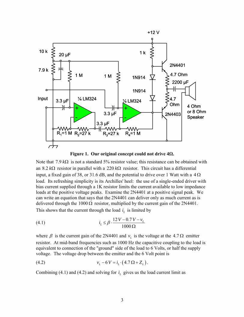
Figure 1. Our original concept could not drive 4Ω.
Note that 7.9 kΩ is not a standard 5% resistor value; this resistance can be obtained with an 8.2 kΩ resistor in parallel with a 220 kΩ resistor. This circuit has a differential input, a fixed gain of 38, or 31.6 dB, and the potential to drive over 1 Watt with a 4Ω load. Its refreshing simplicity is its Archilles' heel: the use of a single-ended driver with bias current supplied through a 1K resistor limits the current available to low impedance loads at the positive voltage peaks. Examine the 2N4401 at a positive signal peak. We can write an equation that says that the 2N4401 can deliver only as much current as is delivered through the 1000 Ω resistor, multiplied by the current gain of the 2N4401. This shows that the current through the load Li is limited by
(4.1) 12 0.71000
LL
V V vi β − −≤ ⋅
Ω
where β is the current gain of the 2N4401 and Lv is the voltage at the 4.7 Ω emitter resistor. At mid-band frequencies such as 1000 Hz the capacitive coupling to the load is equivalent to connection of the "ground" side of the load to 6 Volts, or half the supply voltage. The voltage drop between the emitter and the 6 Volt point is
(4.2) ( )6 4.7L L Lv V i Z− = ⋅ Ω+ .
Combining (4.1) and (4.2) and solving for Li gives us the load current limit as

4
(4.3) 12 0.7 6 5.31000 9.74.7
LL
L
V V V ViZZ
β
− −≤ =
Ω + Ω+ Ω+
with the second form for a β of 200, nominal for the 2N4401 at 100 mA collector current. For a 4 Ω load, this is 0.387 A, which corresponds to a maximum RMS power of 300 mW. Although this power capability is deficient in light of the requirements, we see from the Fairchild data sheet for the 2N44011 that the minimum β at collector currents over 300 mA decreases to values on the order of 50, so that we have a major power shortfall for low impedance loads. Since low impedance loads are the least efficient in terms of perceived sound level at a given power level, this circuit does not meet our requirements for low load impedance; this is an unacceptable limitation.
One solution is to add a Darlington connected driver to the 2N4401 as is often done in op-amp outputs and other power drivers, but adding complexity to the output eliminates the simplicity advantage, so other solutions were examined.
4.1.2 The audio output uses the LM4952 Most boomer audio output chips use a 5 Volts power source. We need 12 Volts as a power source for the other chips in the circuit. The balance, bass, treble and loudness controls were available at minimal cost and complexity through the use of the LM10362, which requires a 12 Volt power source; this means that our design must have a 12 Volt power source which in turn means that 12 Volts is preferred as the power source for other chips. The LM49523 was selected because it provides 3 Watts per channel stereo sound at very low distortion, and it can be driven by an LM1036. It also features thermal shutdown, short circuit protection, and "…advanced pop and click circuitry that eliminates noises which would otherwise occur during turn-on and turn-off transitions." The circuit of Figure 1 has short circuit protection through the inclusion of the 4.7 Ω resistors in the emitter circuits, but to provide for thermal shutdown and anti-pop features would not retain the simplicity of the circuit, or its cost-effectiveness relative to an integrated circuit solution. At a budgetary cost of $1.40 in lots of 1000, the LM4952 is clearly preferred in favor of the discrete output design of Figure 1.
The LM4952 has a singe-ended output, which requires a large 2200 Fμ coupling capacitor to provide 20 Hz response with a 4 Ω load, as does the circuit of Figure 1. Other audio output chips offer differential outputs at similar powers from a 5 Volt power source, with no coupling capacitor required. However, since we need a 12 Volt power source for the LM1036 and an alternative that provides tone and loudness functionality with a 5 Volt power source is not available, the LM4952 is the clear choice. A heat sink is required for the LM4952, which is not surprising because we now have a system that can produce over six watts of audio power.
The details of the design of the DNR, the tone and loudness subsystem, and the power output stage are given in the Appendix under DNR design with the LM1894, Tone control design with the LM1036, and Audio power output with the LM4952, respectively.

5
4.1.3 The base capabilities come from three integrated circuits Once the tone and loudness control chips were selected and a 12 Volt power source were established as the design baseline, the requirements are met and we can look at the goals. The LM1894 provides dynamic noise reduction (DNR) at a chip budgetary cost of $0.91 in lots of 1000, making that goal part of our baseline design and can operate from 12 Volts; the LM1894 data sheet4 specifies performance for a power source of 8 Volts or more, and it features viability for power sources from 4.5 Volts to 18 Volts. The base design uses these audio chips:
• LM1894 DNR, • LM1036 balance, bass, treble, and loudness control, and • LM4952 3 Watt per channel stereo audio power output.
4.1.4 Optional LED light show National Semiconductor offers a chip that will drive three LEDs from different audio bands, offering a light show effect. This is the LM10365, which has a unit price of $0.90 in lots of 1000.
4.1.5 Power supply for battery and AC operation
4.1.5.1 Power supply concept The base power supply concept is to use a battery charger that maintains a rechargeable battery, and to use a boost switching power supply to provide a regulated 12 Volt power source. Running time between charges is a function of battery size. The design will provide a minimum of 1 Ampere-hour, or about 12 Watt-hours, of battery power between charges.
There are two sets of alternatives and trades in the battery maintenance: the battery chemistry and the architecture of the battery maintenance electronics. For miniature portable electronics, there are three viable battery chemistries6. These are summarized in Table 1. The literature on portable batteries often also includes sealed lead-acid in trades, but size, weight, environmental and safety considerations eliminate them from most miniature electronics applications such as the High-Performance Portable Audio Amplifier. Nickel-Cadmium batteries have been largely supplanted by NiMH batteries..
Table 1. Battery Chemistry Alternatives.
Battery Chemistry Principal Advantages Principal Disadvantages
Alkaline Lowest cost
Excellent run time
Excellent shelf life
Not rechargeable
Increases cost of usage
NiMH Good run time between charges Memory effect
Li-Ion High cell voltage
Highest energy density
Higher cost
Calendar limit on life
6
The charge and maintenance algorithms for NiMH and Li-Ion batteries differ. All of them are stated in terms of the maximum charge rate C that can be sustained while the electrolyte can recombine all the gaseous products of charging without venting the cell; this us usually the same as the Ampere-hour capacity of the cell. Each of these is treated in the following sections.
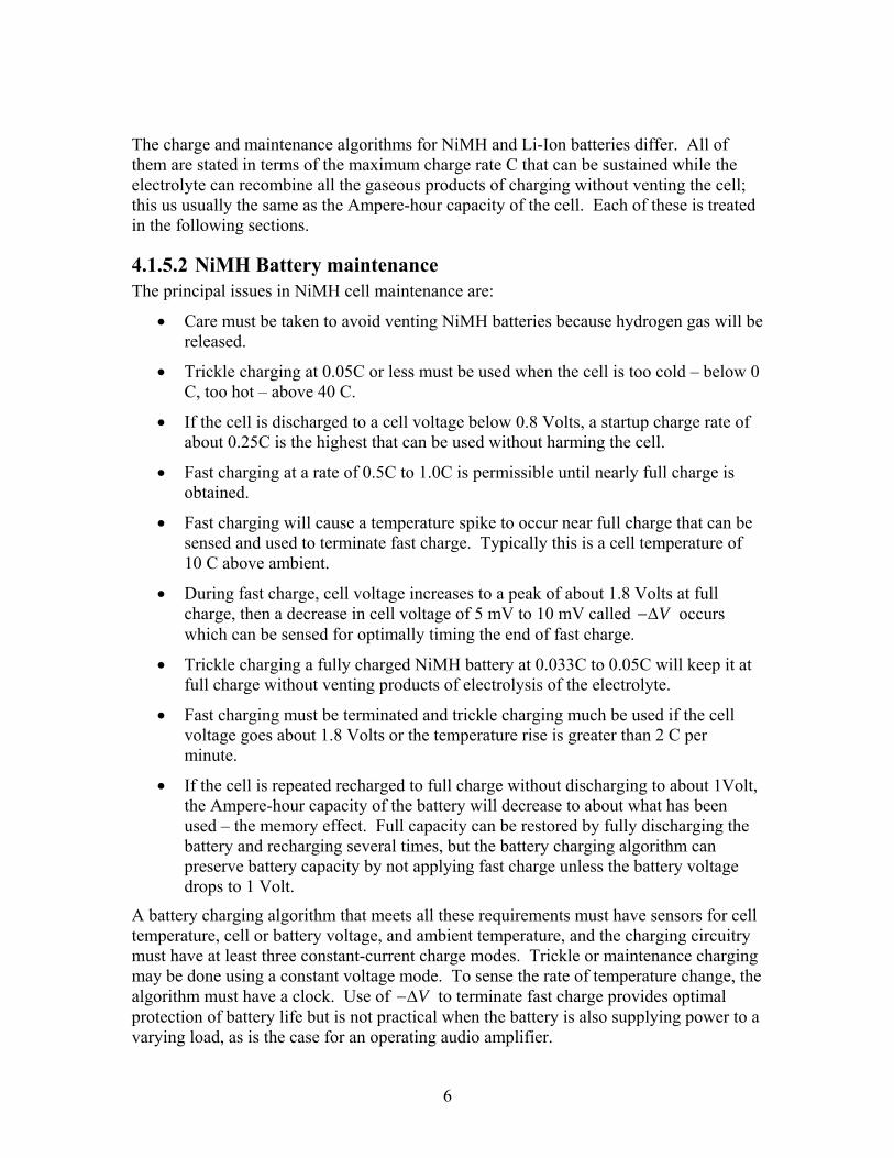
4.1.5.2 NiMH Battery maintenance The principal issues in NiMH cell maintenance are:
• Care must be taken to avoid venting NiMH batteries because hydrogen gas will be released.
• Trickle charging at 0.05C or less must be used when the cell is too cold – below 0 C, too hot – above 40 C.
• If the cell is discharged to a cell voltage below 0.8 Volts, a startup charge rate of about 0.25C is the highest that can be used without harming the cell.
• Fast charging at a rate of 0.5C to 1.0C is permissible until nearly full charge is obtained.
• Fast charging will cause a temperature spike to occur near full charge that can be sensed and used to terminate fast charge. Typically this is a cell temperature of 10 C above ambient.
• During fast charge, cell voltage increases to a peak of about 1.8 Volts at full charge, then a decrease in cell voltage of 5 mV to 10 mV called V−Δ occurs which can be sensed for optimally timing the end of fast charge.
• Trickle charging a fully charged NiMH battery at 0.033C to 0.05C will keep it at full charge without venting products of electrolysis of the electrolyte.
• Fast charging must be terminated and trickle charging much be used if the cell voltage goes about 1.8 Volts or the temperature rise is greater than 2 C per minute.
• If the cell is repeated recharged to full charge without discharging to about 1Volt, the Ampere-hour capacity of the battery will decrease to about what has been used – the memory effect. Full capacity can be restored by fully discharging the battery and recharging several times, but the battery charging algorithm can preserve battery capacity by not applying fast charge unless the battery voltage drops to 1 Volt.
A battery charging algorithm that meets all these requirements must have sensors for cell temperature, cell or battery voltage, and ambient temperature, and the charging circuitry must have at least three constant-current charge modes. Trickle or maintenance charging may be done using a constant voltage mode. To sense the rate of temperature change, the algorithm must have a clock. Use of V−Δ to terminate fast charge provides optimal protection of battery life but is not practical when the battery is also supplying power to a varying load, as is the case for an operating audio amplifier.

7
4.1.5.3 Li-Ion battery maintenance Li-Ion cells and batteries are available in cylindrical cells, prismatic cells, and in polymer sheets. Cell maintenance issues are essentially identical and they will not be discriminated here.
The principal issues in Li-Ion cell maintenance are:
• Trickle charging at 0.1C or less must be used when the cell is too cold – below 0 C, too hot – above 45 C. It is best to suspend charging of Li-Ion cells that are too cold or too hot.
• If the cell is discharged to a cell voltage below 2.8 Volts, a startup charge rate of about 0.1C is the highest that can be used without harming the cell. Li-Ion cells should not be discharged below this level unless the charging algorithm allows for this.
• Fast charging at a rate of 0.5C to 1.0C is permissible until full charge is obtained.
• During fast charge, cell voltage increases to a peak of about 4.2 Volts at full charge.
• Trickle charging a fully charged NiMH battery should be done using constant voltage charging at 4.2 Volts; accuracy of voltage regulation should be 1% or better.
• Temperature changes are small during charging so that temperature sensing is not useful in backstopping other methods for prevention of overcharge.
• Termination of fast charge should be backstopped by timers. Startup charge should terminate if a discharged cell does not charge to 2.8 Volts within 1 hour. For fast charging at g C⋅ , the timer should switch to constant-voltage charging at a time of 1.5 / g hours.
• Termination of trickle or constant voltage charging should be done when the charge current drops below 0.07C, and a backstop time limit of two hours should be used.
A battery charging algorithm that meets all these requirements must have sensors for cell or battery voltage and ambient temperature, and the charging circuitry must have at least two constant-current charge modes and a constant voltage mode. A clock is required to implement the time limits.
4.1.5.4 Battery maintenance electronics alternatives There are three obvious battery maintenance alternatives:
• Discrete battery chargers that use power supplies with regulation circuitry implementing the different charge modes,
• Microcontroller-based solutions that control power regulators, and
• Integrated solutions that implement a pre-planned battery maintenance algorithm.
8
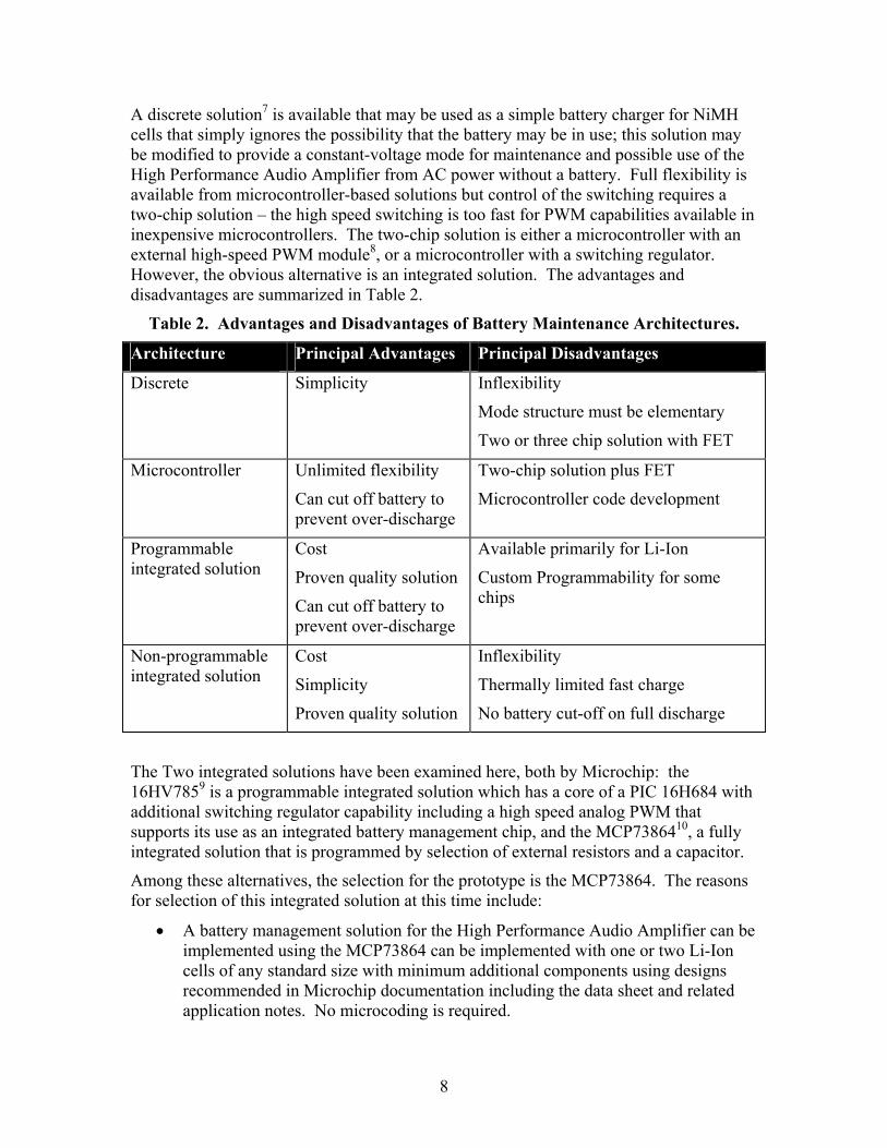
A discrete solution7 is available that may be used as a simple battery charger for NiMH cells that simply ignores the possibility that the battery may be in use; this solution may be modified to provide a constant-voltage mode for maintenance and possible use of the High Performance Audio Amplifier from AC power without a battery. Full flexibility is available from microcontroller-based solutions but control of the switching requires a two-chip solution – the high speed switching is too fast for PWM capabilities available in inexpensive microcontrollers. The two-chip solution is either a microcontroller with an external high-speed PWM module8, or a microcontroller with a switching regulator. However, the obvious alternative is an integrated solution. The advantages and disadvantages are summarized in Table 2.
Table 2. Advantages and Disadvantages of Battery Maintenance Architectures.
Architecture Principal Advantages Principal Disadvantages
Discrete Simplicity
Inflexibility
Mode structure must be elementary
Two or three chip solution with FET
Microcontroller Unlimited flexibility
Can cut off battery to prevent over-discharge
Two-chip solution plus FET
Microcontroller code development
Programmable integrated solution
Cost
Proven quality solution
Can cut off battery to prevent over-discharge
Available primarily for Li-Ion
Custom Programmability for some chips
Non-programmable integrated solution
Cost
Simplicity
Proven quality solution
Inflexibility
Thermally limited fast charge
No battery cut-off on full discharge
The Two integrated solutions have been examined here, both by Microchip: the 16HV7859 is a programmable integrated solution which has a core of a PIC 16H684 with additional switching regulator capability including a high speed analog PWM that supports its use as an integrated battery management chip, and the MCP7386410, a fully integrated solution that is programmed by selection of external resistors and a capacitor.
Among these alternatives, the selection for the prototype is the MCP73864. The reasons for selection of this integrated solution at this time include:
• A battery management solution for the High Performance Audio Amplifier can be implemented using the MCP73864 can be implemented with one or two Li-Ion cells of any standard size with minimum additional components using designs recommended in Microchip documentation including the data sheet and related application notes. No microcoding is required.
9
• Adjustments are very easily made for design changes that become apparent with experience with the prototype, such as use on only one cell, or use of larger Li-Ion cells.
• A battery management solution using the MCP73864 is suitable for a low-cost, high-quality production unit.
In the event that design changes are made later that move us away from the MCP73864, such as use of NiMH batteries instead of Li-Ion cells, we can use one of the other alternatives.
4.1.5.5 Battery maintenance baseline The baseline is to use a linear buck power supply based on the MCP73864 to maintain two Li-Ion cells. The design using the MCP73864 includes a thermistor sensor and this device must be thermally coupled to the Li-Ion cells as closely as reasonably possible. The adapter must provide at least 8.7 Volts to the MCP73864 at full load. The highest fast-charge rate will be the maximum rated capacity of the AC adapter or 0.5C for the Li-Ion cells in use, whichever is smaller.
The AC adapter will be a 9 Volt DC unit such as the Radio Shack 273-1768, which supplies 9 Volts at 800 mA. The battery voltage will be maintained at 8.2 Volts for graphite-anode Li-Ion cells or 8.4 Volts for coke-anode Li-Ion cells.
4.1.5.6 The 12 Volt power supply baseline A simple switching boost power supply based on the LM3478 can provide a step-up power supply that can deliver 1 Ampere at 12 Volts with a minimum of additional components11. Design aids implemented on the National Semiconductor web site as webapps provide device selection and baseline circuit configuration with component values and recommended vendors for the components. The detailed design of the boost power supply for the main 12 Volt power source is given in the Appendix under System 12 Volt power from two Li-Ion cells with the LM3478.
4.2 Design summary
4.2.1 Signal levels All of the chips operate with inputs of 300 mV maximum, and they have a dynamic range that will exceed that available from nearly all audio sources. This is consistent with the 50 mV to 100 mV RMS audio levels commonly provided by sound signal sources such as MP3 players like the iPod and portable radios and DVD players., computer sound card outputs, etc. The level control on the final output stage can be used to tailor the overall gain for the sound source and speakers or headphones in use.
4.2.2 Configuration of Audio Portion The audio signal flow through the functions is shown in Figure 2.

10
DNRLM1894
ControlsLM1036
OutputLM4952
LED DriverLM4970
Three LEDsOr Tri-Color LED
2 2 2 2
3
SpeakersOr Head-Phones
In DNRLM1894
ControlsLM1036
OutputLM4952
LED DriverLM4970
Three LEDsOr Tri-Color LED
2 2 2 2
3
SpeakersOr Head-Phones
In
Figure 2. Configuration of audio signal functions.
4.2.3 Discussion of the power supply configuration The baseline configuration of the battery charger supports occasional recharging of the Li-Ion battery. The baseline configuration supports operation without batteries from the AC adapter, with the battery charger powering the boost 12 Volt power supply. The principal disadvantages of the baseline recommended here for the prototype are that the fast charge time is limited by thermal considerations in the MCM73864, and the lack of provision for cutting off the battery at full discharge to prevent permanent battery damage. The effective 5-year limit on the life of Li-Ion batteries is not considered important for this product because that is about the life cycle of the product.
An alternative configuration is a more sophisticated battery charger based on a microcontroller. With a microcontroller, full fast charge can be maintained without thermal limiting concerns, cutting off the battery at a minimum voltage requires only that a FET switch be added between the battery and ground, and more complex charge versus time profiles such as gradual ramp-up to rapid charge are simple to implement and a new mode for supporting maintenance of the battery full charge while providing power for the audio amplifier. However, PWM controlled switching for a buck regulator driven from a microcontroller requires an external PWM chip to achieve sufficiently high switching speeds to keep the small external component size and energy efficiency achieved with simple switching regulators.
Microchip supports the use of microcontrollers for smart power supply usage [8]. Their PIC line also supports mastering the I2C bus with the microcontroller through the MSSP and SPI capability, which would provide a no-cost transparent means to enable use of the I2C bus capabilities of the LM4970, shutdown control on the LM4952, and possible use of a MOSFET switch to disconnect the battery when its voltage drops below 7.4 Volts to prevent damage.

11
BatteryCharger
MCM73864LM2576Or PIC
12 VoltBoost
LM2587
TwoLi-IonCells
9-12 VSystem12 VoltPower
BatteryCharger
MCM73864LM2576Or PIC
12 VoltBoost
LM2587
TwoLi-IonCells
TwoLi-IonCells
9-12 VSystem12 VoltPower
Figure 3. Power supply configuration.
5 Conclusions
5.1 Results A baseline that meets all the requirements and goals of Section 3 is provided with a five-chip solution. Significant additional components are limited to two Li-Ion AA cells, a MOSFET and Schottky diode for the boost regulator, and a flyback inductor for the boost regulator. Cost and risk is low, and producibility in any quantity is supported by this design. One heat sink is required one for audio power output; charging performance is enhanced if a heat sink is added to the MCM78364.
5.2 Recommendations The battery charger concept is inflexible, fast charge current and time is limited by thermal considerations, and there is no provision to cut off the battery at minimum charge to prevent damage. A second sample design in the National Semiconductor Application Note AN-94612 provides for a bucking regulator circuit that is used with a microcontroller. With this concept, all the disadvantages of the current design can be addressed.
The battery recommended here has 10 to 25 Watt-hours of energy storage. Only experience with the prototype can resolve this to provide accurate requirements for the battery. Since the battery is the cost driver for the entire product, special attention must be given to battery life requirements during prototype testing. Note that battery life depends on the headphones or speaker in use, with lower speakers using more power than headphones, and lower impedance headphones using more power than high impedance headphones.
Additionally, the configuration of the power supply may need to be changed to maintain a quiet, robust portable audio amplifier. If necessary, the boost power supply can be adjusted to provide 13 Volts instead of 12 Volts, and 7812 voltage regulators can be used to provide low-ripple power to the power output chip and a separate 7812 can provide power for the DNR and tone control chip if necessary to prevent motorboating.


13
Appendix
6 DNR design with the LM1894 The input stage of the high-performance audio amplifier is the LM1894 dynamic noise reduction subsystem. The configuration of the use of this chip is given in the National Semiconductor data sheet for the LM1894 and is given from that source as Figure 4. The inductor-capacitor pair L8-CL is a 19 kHz trap for use with FM radio systems that isn't needed in our application. We will replace L8-CL with a connection between C9 and R8. A PC board layout for this configuration is included in the National Semiconductor data sheet13.
The two resistors R1 and R2 need to be a 1 kΩ potentiometer in the prototype, and the wiper connected to C6; this adjustment sets the onset of noise abatement by high frequency rolloff. These resistors will be fixed values after experience with the prototype gives us the proper adjustment for best performance.
Figure 4. LM1894 usage for DNR® from [4].
7 Tone control design with the LM1036 The application of the LM1036 is shown from the National Semiconductor data sheet [2] as Figure 5. Note that all the controls are DC controls with their reference from pin 17, which is an internal Zener-stabilized low noise reference. There is one option discussed in the data sheet application discussion – a modification of the volume control for additional bass boost. This involves reducing Cb from 0.39 Fμ to 0.22 Fμ and replacing the 47 kΩ volume control potentiometer with a 25 kΩ potentiometer with additional 5 kΩ resistors between the potentiometer and ground, and between the

14
potentiometer and the reference voltage. The output coupling capacitors are not given in the schematic of Figure 5 because the impedances of the next stage is not part of the design. Knowing that the input impedance of the next stage is over 10 kΩ , we will use 0.47 Fμ .
Figure 5. LM1036 tone and volume control usage from [2].
8 Audio power output with the LM4952 The audio power output stage usage is shown from the National Semiconductor data sheet [3] as Figure 6. Note that there is a DC controlled level control that will likely be useful in setting up the production, or we may make it available to the user as a level control that is set by hand for the particular speaker or headphone in use. The National Semiconductor data sheet recommends that this control be a 25 kΩ potentiometer with a 10 Fμ capacitor to ground from the wiper, and a 91 kΩ resistor from the high end of the potentiometer to the 12 Volt power source. The 10 Fμ capacitor provides for constant perceived volume for power supply voltage droop when driving 4 Ω loads at high power levels.

15
Figure 6. LM4952 audio power output usage from [3].
9 Optional enhancement: Audio synchronized LEDs with the LM4970
The LM4970 can provide audio synchronized LEDs at minimal cost and complexity. A diagram of the LM4970 from the National Semiconductor data sheet [5] is shown below as Figure 7. All that is required is to couple in the stereo channels out of the ADR chip and wire the LEDs. Power is from a source of 3 V to 6 V, which can be provided directly from the batteries through a diode drop. The bands that match the three LEDs can be varied by changing Cfilt over a range of 0.1 Fμ to 2.2 Fμ . LED brightness is controlled by PWM at about 60 Hz and no dropping resistor is required, but the LEDs probably will work best if they are driven from the 12 Volt power source.
The I2C interface is not used, unless the battery charger is changed from a National Semiconductor LM2576 to a PIC microcontroller, a PWM chip controlled by the PIC and a MOSFET switch, in which case the I2C bus can be controlled by the PIC. The data and clock lines of the I2C interface, labeled SCL and SCD in Figure 2, are held high when the bus is not used.
There are three inputs. The inputs are to the LIN and RIN pins and the MIN input is not used. This pin could be used for the microphone channel for PA or karaoke use.

16
Figure 7. Usage of the LM4970 from [5].
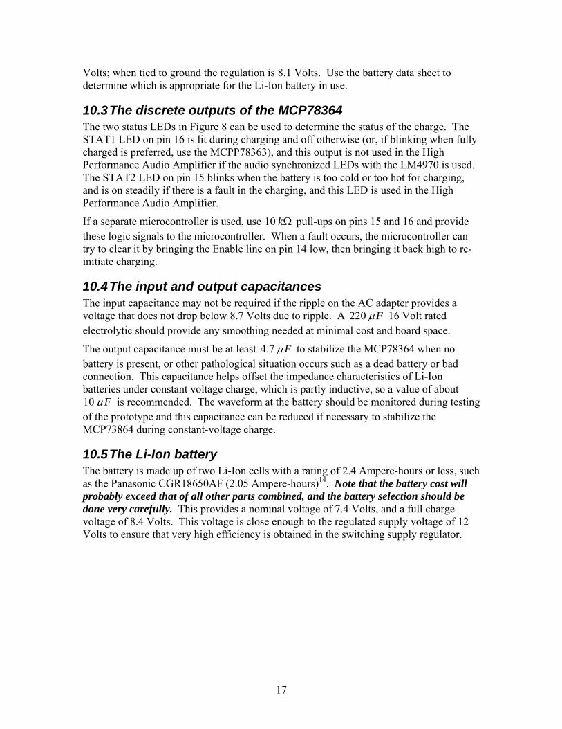
10 Battery charger with the MCP78364
10.1 The MCP78364 integrated Li-Ion battery maintenance chip Lithium Ion (Li-Ion) Battery charging and maintenance with the Microchip Technology MCP73864 is presented here. This chip is one of a series of four similar integrated solutions for Li-Ion battery maintenance; the MCP73864 is intended for two-cell (nominal 7.4 Volt) batteries and the MCP73862 is intended for single-cell (nominal 3.7 Volt) batteries. The circuit is shown in Figure 8; this circuit was modified from the example given in the data sheet [10]. The QFN package that is shown in Figure 8 should be used because it has a thermal resistance of 37 C/Watt, while the SOIC package has a thermal resistance of 74 C/Watt. The thermal resistance should be improved over this nominal value by using The MCP73864 is a linear regulator and will reduce the charge current to limit the die temperature, so improving the thermal coupling of the MC73864 is equivalent to increasing the charge current during the rapid-charge mode.
10.2 The discrete inputs to the MCP78364 The Enable input on pin 14 should be connected to the input unregulated voltage as shown in Figure 8 unless a separate microcontroller is used. If a separate microcontroller is present, this signal can be used to start and stop charging.
The input SETV on pin 1 determines whether the constant voltage charge mode of the MCP78364 is 8.1 Volts or 8.2 Volts. When tied high as in Figure 8, the regulation is 8.2
17
Volts; when tied to ground the regulation is 8.1 Volts. Use the battery data sheet to determine which is appropriate for the Li-Ion battery in use.
10.3 The discrete outputs of the MCP78364 The two status LEDs in Figure 8 can be used to determine the status of the charge. The STAT1 LED on pin 16 is lit during charging and off otherwise (or, if blinking when fully charged is preferred, use the MCPP78363), and this output is not used in the High Performance Audio Amplifier if the audio synchronized LEDs with the LM4970 is used. The STAT2 LED on pin 15 blinks when the battery is too cold or too hot for charging, and is on steadily if there is a fault in the charging, and this LED is used in the High Performance Audio Amplifier.
If a separate microcontroller is used, use 10 kΩ pull-ups on pins 15 and 16 and provide these logic signals to the microcontroller. When a fault occurs, the microcontroller can try to clear it by bringing the Enable line on pin 14 low, then bringing it back high to re-initiate charging.
10.4 The input and output capacitances The input capacitance may not be required if the ripple on the AC adapter provides a voltage that does not drop below 8.7 Volts due to ripple. A 220 Fμ 16 Volt rated electrolytic should provide any smoothing needed at minimal cost and board space.
The output capacitance must be at least 4.7 Fμ to stabilize the MCP78364 when no battery is present, or other pathological situation occurs such as a dead battery or bad connection. This capacitance helps offset the impedance characteristics of Li-Ion batteries under constant voltage charge, which is partly inductive, so a value of about 10 Fμ is recommended. The waveform at the battery should be monitored during testing of the prototype and this capacitance can be reduced if necessary to stabilize the MCP73864 during constant-voltage charge.
10.5 The Li-Ion battery The battery is made up of two Li-Ion cells with a rating of 2.4 Ampere-hours or less, such as the Panasonic CGR18650AF (2.05 Ampere-hours)14. Note that the battery cost will probably exceed that of all other parts combined, and the battery selection should be done very carefully. This provides a nominal voltage of 7.4 Volts, and a full charge voltage of 8.4 Volts. This voltage is close enough to the regulated supply voltage of 12 Volts to ensure that very high efficiency is obtained in the switching supply regulator.
18
Figure 8. Battery maintenance using the MCP73864, modified from [10].
10.6 Component values in the battery maintenance circuit
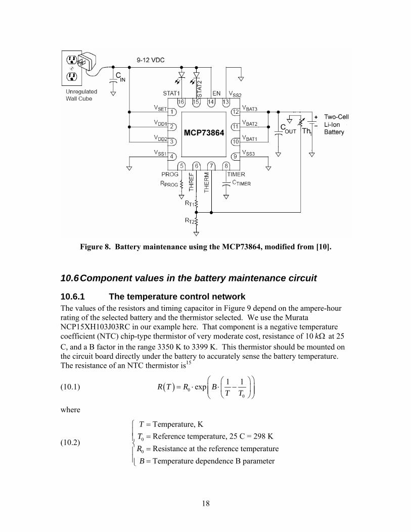
10.6.1 The temperature control network The values of the resistors and timing capacitor in Figure 9 depend on the ampere-hour rating of the selected battery and the thermistor selected. We use the Murata NCP15XH103J03RC in our example here. That component is a negative temperature coefficient (NTC) chip-type thermistor of very moderate cost, resistance of 10 kΩ at 25 C, and a B factor in the range 3350 K to 3399 K. This thermistor should be mounted on the circuit board directly under the battery to accurately sense the battery temperature. The resistance of an NTC thermistor is15
(10.1) ( ) 00
1 1expR T R BT T
⎛ ⎞⎛ ⎞= ⋅ ⋅ −⎜ ⎟⎜ ⎟⎜ ⎟⎝ ⎠⎝ ⎠
where
(10.2) 0
0
Temperature, KReference temperature, 25 C = 298 KResistance at the reference temperatureTemperature dependence B parameter
TTRB
=⎧⎪ =⎪⎨ =⎪⎪ =⎩

19
For the NCP15XH103J03RC, this provides a resistance of 28 kΩ at 0 C and a resistance of 5.8 kΩ at 40 C. From the data sheet for the MCP73864 [10], the resistances in the thermistor network are given by
(10.3) 12 2COLD HOT
T COLD HOTCOLD HOT
R RR R RR R⋅ ⋅
= = ⋅ ⎡ ⎤⎣ ⎦−
and
(10.4) 22 2 3
3 3COLD HOT
T COLD HOTCOLD HOT
R RR R RR R⋅ ⋅
= = ⋅ ⎡ ⋅ ⎤⎣ ⎦− ⋅.
For the NCP15XH103J03RC, this is 9.64 kΩ (10 kΩ in parallel with 270 kΩ ) and 30.44 kΩ ( 33 kΩ in parallel with 400 kΩ ).
10.6.2 The current limit control resistor The MCP73864 has a maximum charge current rating of 1.2 Amperes, and we want to charge our Li-Ion battery at a maximum current of C/2. Thus the current regulation mode will have a current of
(10.5) MIN 1.2 ,2REGCI A⎛ ⎞= ⎜ ⎟
⎝ ⎠
The current limit programming resistor should have a value of [10]
(10.6) 13.2 1112 1.2
REGPROG
REG
IR kI− ⋅
= Ω⋅ −
.
This allows variation of the regulation current from 100 mA when PROGR is not used and pin 5 is allowed to float (i.e. not connected) to 1.2 Amperes when pin 5 is connected to ground.
10.6.3 The timing capacitor The timing capacitor is used for the time limit backstops for preconditioning trickle charge, current limited charge, and constant voltage charge, and to set the blink rate of the LED when a charging fault is found. To set these times properly, this capacitance should be [10]
(10.7) 0.1TIMERREG
CC FI
μ⎛ ⎞
= ⋅⎜ ⎟⎝ ⎠
where C is the ampere-hour rating of the battery. This capacitance is 0.2 Fμ if C/2 is less than 1.2 Amperes, or the higher value of /12C Fμ if the maximum current available of 1.2 Amperes is used.

20
11 System 12 Volt power from two Li-Ion cells with the LM3478
National Semiconductor has an automated design capability on their web site that they call WEBENCH®16. Exercising this web application for a power supply that would convert an input voltage of 7.4 Volts to 8.4 Volts to produce 12 Volts at 1 Ampere resulted in a recommendation of the LM2585-12 with an efficiency of 80%. The per-unit cost of the LM2585-12 is given as $3.17, apparently in quantities of 1,000. The LM3478 is offered as an alternative, with an efficiency of 85% and a per-unit cost of $0.89, so the LM3478 was selected. The resulting design is the schematic shown below as Figure 9.
Figure 9. Boost power supply using the LM2587 from [16].
A trade between a footprint of about 3.3 square cm and an efficiency of 91% is offered, but asking for maximum efficiency produces the same efficiency and the board space goes up to 17 square cm so the default design is presented here.
The switching frequency is about 500 kHz. A heat sink is required for the switching MOSFET that produces a junction to ambient thermal resistance of 50 C/Watt. A rather amazingly low output ripple of 0.6 mV peak-to-peak is predicted for 4 Volts input and 1 Ampere output, a worst case. The highest power dissipations are 0.8 Watt in the Zener diode, 0.3 Watt in the MOSFET and about 0.2 Watt in the inductor.
The WEBENCH® recommendations for parts for the circuit shown in Figure 9 are shown in Table 3. The resistor Rdr is given as zero, but this resistor is used to control dV/dt and for stabilizing the MOSFET M1 during switching; the data sheet shows this resistor to be omitted for switching speed tests but if difficulties of any kind are

21
encountered, I suggest a value of 22 Ω . The value of Rsense is given to several decimal places but a simple 0.91Ω resistor in parallel with an 0.075Ω resistor should suffice.
Table 3. Parts for the circuit of Figure 9.
Part Manufacturer Part No. Key Specification
Cbyp TDK C2012X7R2A104K 0.1 μF
Ccomp Kemet C0805C124K5RACTU 0.12 μF
Cin Panasonic EEV-FK1C100R 10 μF,
1.35 Ohms
Cout TDK C3225X5R1C226M 22 μF,
0.002 Ohms
Csense MuRata GRM2195C1H103JA01D 0.01 μF
D1 Diodes Inc. B320A-13 0.5 V
L1 Coiltronics DR74-220-R 22 μH,
0.0637 Ohms
M1 International Rectifier
IRF7493 1.5nF,
0.0115 Ohm
Rcomp Panasonic ERJ-6ENF1001V 1000 Ohm
Rdr Custom Custom 1.0E-6 Ohm
Rfadj Panasonic ERJ-6GEYJ303V 30000 Ohms
Rfb1 Panasonic ERJ-6ENF9760V 976 Ohms
Rfb2 Panasonic ERJ-6ENF8451V 8450 Ohms
Rs1 Panasonic ERJ-8ENF6040V 604 Ohms
Rsense Custom Custom 0.06952 Ohm
IC National Semiconductor
LM3478 N/A

22
References 1 2N4401/MBT4401, Fairchild Semiconductor data sheet for the 2N4401, Revision A (2001), ON characteristics on page 2, and plot of current gain versus collector current on page 3. 2 LM1036: Dual DC Operated Tone/Volume/Balance Circuit, National Semiconductor document DS005142, data sheet for the LM1036, January 1995. Available from http://www.national.com/. 3 LM4952: 3.1W Stereo-SE Audio Power Amplifier with DC Volume Control, National Semiconductor document DS200809, data sheet for th eLM4952. 4 LM1894: Dynamic Noise Reduction System DNR®, National Semiconductor document DS007918, data sheet for the LM1894, April 2002. 5 LM4970: Audio Synchronized Color LED Driver, National Semiconductor document DS201212, data sheet for the LM4970, May 2005. 6 Selecting the Right Battery System for Cost-Sensitive Portable Applications while Maintaining Excellent Quality, Microchip Application Note AN1088, document DS0188A, dated 2007. 7 High-Efficiency 3A Battery Chargers Use LM2576 Regulators, National Semiconductor Application Note AN-946, by Chester Simpson, May 1994. 8 New Components and Design Methods Bring Intelligence to Battery Charger Applications, Microchip Application Note AN-960, October 20, 2004. 9 PIC16F785/HV785: 20-Pin Flash-Based, 8-Bit CMOS Microcontroller with Two-Phase Asynchronous Feedback PWM Dual High-Speed Comparators and Dual Operational Amplifiers, Microchip document DS41249D, data sheet for the PIC 16HV785, labeled PRELIMINARY, dated 2006. 10 MCP73861/2/3/4: Advanced Single or Dual Cell, Fully Integrated Li-Ion/Li-Polymer Charge Management Controllers, Microchip document DS21893C, data sheet for the MCP73861 series of Li-Ion battery management chips, dated 2005. 11 LM3478: High Efficiency Low-Side N-Channel Controller for Switching Regulator, National Semiconductor document DS101355, data sheet for the LM3478, March 2005. 12 National Semiconductor Application Note AN-946, pp 3-5. 13 National Semiconductor data sheet for the LM1894, loc. cit., p. 10. 14 Panasonic data sheet for the CGR18650AF cylindrical Li-Ion cell, dated January 2007. 15 NTC Thermistors, MuRata document R44E-9, dated May 13, 2005, available from http://www.murata.com/thermis/index.html . 16 National Semiconductor web site, http://www.national.com/, select Power Management, then enter the input and output requirements in the Design block. When the initial design is complete, the program will present an optimization tradeoff, and select maximum efficiency, then click "Optimize."


