J. Fluid Mech. (1996), uol. 309, pp. 321-344 Copyright 0 1996 Cambridge University Press 321 A laboratory simulation of mixing across tidal fronts By P. J. THOMAS? AND P. F. LINDEN Department of Applied Mathematics and Theoretical Physics, University of Cambridge, Silver Street, Cambridge CB3 9EW, UK (Received 28 June 1995 and in revised form 6 November 1995) A laboratory study which simulates the dynamics of shallow sea fronts and the mixing across a tidal front is described. The experiments show, for the first time, that it is possible to simulate a stationary tidal front with the inclusion of buoyancy effects, Coriolis effects and turbulence in the laboratory. Experimental data obtained for the cross-front mixing rate are presented. The data analysis shows that the mixing rate increases with stratification and decreases with rotation. A theoretical model of the flow which collapses the experimental data is developed which shows that the cross-front mixing is controlled by baroclinic processes. The model enables an extrapolation of the laboratory results to oceanographic conditions. Estimates of the cross-front mixing velocity for oceanographic conditions give values consistent with estimates obtained from North Sea data. 1. Introduction For several years it has been firmly established that regions displaying sharp horizontal gradients of quantities such as temperature, salinity or density are a common feature to be observed in shelf seas. Such regions are referred to as fronts, and the evidence for their existence was originally provided by ship surveys and more recently by infra-red satellite images of the sea surface. On infra-red images the fronts reveal themselves through sharp changes in the sea surface temperature and, for much of the year, they represent the largest horizontal temperature gradients present. Fronts in shelf seas are often seasonal and they are generally a result of variations in the level of tidal stirring. During the summer months these variations and the stratifying effect of the solar radiation result in a division of the shelf sea into well- mixed and stratified zones, on lengthscales of a few kilometres, which are separated by a front. In deeper water a thermocline develops, while in shallower water, where the tidal stirring is stronger, a well-mixed water column is maintained. At the boundary of this mixed region the thermocline bifurcates and intersects the surface and the bottom producing fronts. One typical example of such a front is the Flamborough Head front in the North Sea (Hill et al. 1993). The dynamics of the frontal zone is complex as it involves the interplay of buoyancy effects, Coriolis forces and turbulence. The buoyancy and Coriolis forces produce a geostrophic flow along the front and the frontal boundary usually displays a marked eddy structure (Pingree 1978,1979; Griffiths & Linden 1981; t Present address: Department of Engineering, University of Wanvick, Coventry CV4 7AL, UK; e-mail: [email protected].
Transcript
J. Fluid Mech. (1996), uol. 309, pp. 321-344 Copyright 0 1996 Cambridge University Press
321
A laboratory simulation of mixing across tidal fronts
By P. J. THOMAS? AND P. F. LINDEN Department of Applied Mathematics and Theoretical Physics, University of Cambridge,
Silver Street, Cambridge CB3 9EW, UK
(Received 28 June 1995 and in revised form 6 November 1995)
A laboratory study which simulates the dynamics of shallow sea fronts and the mixing across a tidal front is described. The experiments show, for the first time, that it is possible to simulate a stationary tidal front with the inclusion of buoyancy effects, Coriolis effects and turbulence in the laboratory. Experimental data obtained for the cross-front mixing rate are presented. The data analysis shows that the mixing rate increases with stratification and decreases with rotation. A theoretical model of the flow which collapses the experimental data is developed which shows that the cross-front mixing is controlled by baroclinic processes. The model enables an extrapolation of the laboratory results to oceanographic conditions. Estimates of the cross-front mixing velocity for oceanographic conditions give values consistent with estimates obtained from North Sea data.
1. Introduction For several years it has been firmly established that regions displaying sharp
horizontal gradients of quantities such as temperature, salinity or density are a common feature to be observed in shelf seas. Such regions are referred to as fronts, and the evidence for their existence was originally provided by ship surveys and more recently by infra-red satellite images of the sea surface. On infra-red images the fronts reveal themselves through sharp changes in the sea surface temperature and, for much of the year, they represent the largest horizontal temperature gradients present.
Fronts in shelf seas are often seasonal and they are generally a result of variations in the level of tidal stirring. During the summer months these variations and the stratifying effect of the solar radiation result in a division of the shelf sea into well- mixed and stratified zones, on lengthscales of a few kilometres, which are separated by a front. In deeper water a thermocline develops, while in shallower water, where the tidal stirring is stronger, a well-mixed water column is maintained. At the boundary of this mixed region the thermocline bifurcates and intersects the surface and the bottom producing fronts.
One typical example of such a front is the Flamborough Head front in the North Sea (Hill et al. 1993). The dynamics of the frontal zone is complex as it involves the interplay of buoyancy effects, Coriolis forces and turbulence. The buoyancy and Coriolis forces produce a geostrophic flow along the front and the frontal boundary usually displays a marked eddy structure (Pingree 1978,1979; Griffiths & Linden 1981;
t Present address: Department of Engineering, University of Wanvick, Coventry CV4 7AL, UK; e-mail: [email protected].
322 P. J. Thomas and P. F. Linden
Linden 1991). The front itself tends to act as a barrier to horizontal transport between the stratified and mixed regions. However, as horizontal gradients of properties are large across a front, it is a place of potentially strong horizontal exchange. Pollutants or nutrients may be trapped on one side of the front such that the front and the cross-front fluid exchange become a major factor in the coupling of the coastal region and the deeper sea (see, for instance, Le FZvre 1986). In addition, the different nature of the water column on either side of the front means that quite different processes may operate on the two sides.
The modelling of frontal dynamics and the cross-front mixing has in the past been the scope of various theoretical studies (Pingree & Griffiths 1978; James 1983, 1990; Garrett & Lodder 1981). However, despite the obvious importance of cross-front mixing, apparently there are no experimental laboratory studies which investigate the inclusion of the essential factors of buoyancy effects, Coriolis forces and turbulence. The study of turbulent mixing under the influence of rotation across a primarily horizontal density interface, on the other hand, has been the interest of various authors (e.g. Fleury et al. 1991, and for an overview see Fernando 1991). However, in this type of experiment the fluid exchange is primarily vertical. Hence, it cannot be expected that these experiments will accurately simulate the mixing processes across a tidal front with its primarily horizontal fluid exchange. Of the available studies the work most closely related to the present investigation is the experiment of Ivey (1987) which was concerned with boundary mixing. It was motivated by the suggestion by Munk (1966) that mixing in the deep ocean could be due predominantly to boundary mixing which can be driven for instance by the mean flow interacting with the bottom of the ocean or by bottom reflections of internal waves. In order to study boundary mixing Ivey used a roughened vertical cylinder placed centrally in a rotating tank and which mixed a stably stratified two-layer fluid. The cylinder was oscillated vertically thereby producing a boundary layer next to the cylinder in which turbulence caused vertical mixing. One of Ivey’s main results is that the rate of vertical mixing is not affected by rotation.
In order to simulate mixing processes associated with tidal fronts rather than boundary mixing the mechanism for the generation of turbulence was different in the present study. As will be described in detail below, the mixing in our study is produced by turbulence generated by means of an oscillating flat circular (rather than cylindrical) grid stirring a rotating two-layer fluid. The mixing due to the grid motion initially establishes a region which is separated from the ambient fluid by a horizontal density gradient. Consequently, further mixing across this front relies on a horizontal cross-front fluid entrainment, and the entrainment must be expected to depend on the rate of rotation as well as on buoyancy effects associated with the density anomality across the front. The main goal of this study is to determine how the cross-front fluid exchange depends on these aspects. The methodology is to carry out laboratory experiments which simulate the essential features of the dynamics of a tidal front, and to measure directly the cross-front fluid transport. A theoretical model of the flow is developed which collapses the experimental data and enables the extrapolation of the laboratory results to oceanographic conditions for a comparison with North Sea data.
2. Experimental set-up The experiments were carried out in a circular Perspex tank with a radius of
R = 44.7 cm and a height of 30 cm. The tank was positioned on a computer-
A laboratory simulation
Light source
of mixing across tidal fronts 323
- Grid drive gear box Light sheet ';
1 Grid motor
/- Perspex tank
Rotating turntable
U FIGURE 1. Sketch of the experimental set-up. For the sake of clarity several experimental set-up which i r e not essentiai for the principle understanding are not included in the figure. These include mirrors and other equipment required fo; the flow visualization which were located at various positions on the table. (Sketch not to scale).
components of the of the exDeriments
controlled rotating turntable (figure 1). Mixing and the generation of a front was achieved by a grid oscillating in a stably stratified environment.
For each run of the experiment the stably stratified environment consisted of a bottom layer of brine with a density p1 and a top layer of fresh water with a lower density p~ < p1. The two-layer system was set up by filling the tank initially with the required amount of the dense brine, spinning it up and letting it reach a state of solid-body rotation. The lighter fresh fluid was then carefully added on top of the dense brine through a floating sponge. Prior to each run of the experiment the two layers were of approximately equal volumes and they were separated by a density interface with a thickness of approximately 1.5 - 2 cm.
The initial strength of the stratification can be characterized by the reduced gravi- tational acceleration g' which is defined as
P1 - P2
P1 g ' = g ~
where g is the gravitational acceleration. The experiment was carried out for values of g' between approximately 0.4 cm s-' and 32 cm s-'. The rotation rate 52 of the turntable was varied between 0 rad s-' and 2.0 rad s-'.
In order to mix the fluid from the bottom and top layers and to generate a front with a horizontal density gradient, a circular grid which could be oscillated through the fluid by means of an attached driving mechanism was mounted on the turntable (see figures 1 and 2). The grid was positioned horizontally and such that its centre coincided with the axis of rotation of the turntable. The circular grid had a radius
324 P. J . Thomas and P. F. Linden
Bottom layer
FIGURE 2. A simplified sketch of a vertical cross-section of the fluid in the tank for a the fully devel- oped three-layer system. The sketch illustrates some of the nomenclature encountered throughout the text.
of rg = 8.1 cm, with a square mesh of 1 cm x l cm of square bars (2 mm x2 mm) resulting in an open grid area of 64 %. During each run of the experiment the two fluid layers in the tank were stirred by oscillating the grid with a constant frequency of fg . = 0.1 Hz vertically through the fluid. The grid frequency was chosen low enough to minimize the introduction of perturbations due to the grid oscillation. The amplitude of the oscillation was also kept constant (approximately 5 cm) for all runs of the experiment, and equal to half of the total fluid height in the centre of the rotating tank. The two layers were thus stirred about the mid-depth from the bottom of the tank to the surface of the top layer by the turbulence induced by the wakes of the grid bars. As a consequence of the constant stirring amplitude the actual fluid volume of the bottom layer had to be slightly different for the different rotation rates in order to obtain the same fluid height at the centre of the tank.
When the grid oscillation starts the brine of the bottom layer and the fluid of the less dense top layer begin to mix. This mixing establishes a cylindrical region of fluid of intermediate density which is initially confined to the centre of the tank. Owing to the action of gravity the mixed fluid starts to spread radially outwards and subsequently develops into a separate middle layer of intermediate density. A simplified sketch of a vertical cross-section of the fluid in the tank after the middle layer has developed is shown in figure 2; this figure serves to illustrate some of the nomenclature used throughout the text.
Two series of experiments were carried out. The first series was involved with the early stages of the experiment before the radially spreading mixed fluid had reached the outer wall of the tank, and concentrated on the temporal growth of the mixed region. The second series was involved with the temporal development of the volume of the fluid layers after the mixed fluid had reached the wall of the tank and the middle layer had been fully established.
Flow visualization was achieved by injecting a small amount of dye into the stirred region such that it became distributed throughout the mixed fluid regime. For the first series of experiments during which the initial radial spreading of the mixed fluid was to be monitored the injected dye was dark food colour. When observed from above the tank the mixed region then became visible as a dark patch against the white bottom
A laboratory simulation of mixing across tidal fronts 325
of the tank (see figure 3b). For the second series of experiments a fluorescent dye (Fluorescein) was used and a vertical light sheet, orientated as indicated in figure 1, was used to illuminate half a cross-section of the fluid in the rotating tank. In the illuminated section of the tank the mixed layer containing the fluorescent dye then became distinguishable from the adjacent layers above and below (see figure 3a,c) and its growth in height was observed through the sidewall of the tank.
The experiments were filmed using a video camera mounted on the rotating turntable. The video tapes were analysed by means of the image processing system DigImage (Dalziel 1994) developed at DAMTP.
For the first series of experiments concerned with the initial radial spreading of the mixed fluid the data analysis proceeded as follows. The spreading region was filmed from above the tank where, as described above, the mixed fluid was visible as a dark patch against a white background. The outline of the dark patch was determined by setting a threshold intensity for the pixels on the video monitor. The number of pixels on the monitor lying within the traced region was determined, and this number was then compared with a predetermined calibration curve displaying the functional (linear) relation between the area and the number of pixels. Froa the value obtained for the patch area a mean radius Rp was determined as the radius of a circle of area equal to the dark patch. The error involved in the determination of the patch area was found to be of the order of 1-3% and was due to the necessity of having to choose a pixel intensity corresponding to the patch boundary.
For the second series of experiments which was concerned with the monitoring of the volume of the fluid layers the data analysis proceeded as follows. The region of the tank intersected by the vertical light sheet was filmed through the wall of the tank. Owing to the fluorescent dye the mixed layer was brightly lit up and its layer boundaries could be identified. The layer boundaries were then traced and the coordinates pertaining to a number of chosen points on the boundary were written out to a computer file. Assuming rotational symmetry of the boundaries around the axis of rotation the volumes of the three fluid layers at some instant in time were then determined. The principal evaluation procedure for the determination of the layer volumes is based on a finite difference algorithm. The algorithm employs the appropriate summing of sequences of volumes of truncated cones based on the coordinates of successive points lying on the traced layer boundaries. For each run of the experiment the layer volume was determined for approximately 1540 instants in time and each boundary was marked by typically around 30-60 points. The error involved in the determination of a volume defined by the traced boundary by means of this procedure is estimated to be of the order of approximately 1-370. However, owing to temporally varying random local interface deformations the scatter of the determined volume data can be significantly larger than expected from this error estimate as the assumption of rotational symmetry around the axis of rotation is violated by the occurrence of such deformations.
In addition to the visual observation of the mixing process, a salinity probe was mounted on the turntable. With this salinity probe the fluid density could be monitored either at one chosen location within the fluid as a function of time or, alternatively, at one radial position as a function of the height above the bottom of the tank.
326
3 . Theoretical considerations 3.1. A theoretical model for the initial radial collapse of the mixed fluid.
We will now derive an expression describing the temporal development of the mean radial extent of the radially collapsing mixed fluid before it has reached the wall of the tank, i.e. before the full three-layer system has been established. The result obtained here, together with the results presented below, will enable us to determine the value of a Froude number associated with the radial propagation of the front. It will then be possible to use these results to determine the cross-frontal mixing rate.
P. J. Thomas and P. F. Linden
We define the Froude number F for the collapsing mixed fluid as
where u is the mean radial velocity of the spreading boundary and h, is some measure for the mean height of the collapsing mixed fluid. The effect of rotation in the frontal zone will affect the spread of mixed fluid and so F will depend on the rotation rate s1. Nevertheless, for a given experiment F can be assumed to be constant during the radial collapse of the mixed fluid. Its numerical value will, however, be modified by the rotation with respect to the non-rotating case.
Since the conditions near the grid do not change until the mixed region reaches the outer wall of the tank, it is reasonable to assume that the volume flux into the mixed region is constant during this early stage. This volume flux is determined by the entrainment across the front with velocities u1 and u2 and the depth and the radial position of the front - see figure 2. Continuity requires that this volume flux is equal to the volume flux q radially outwards which is given by
q = 2nRPh,u, ( 3 )
where Rp is the mean radius of the radially spreading patch as defined above in $2. From ( 2 ) and (3), and noting that
u = - dRP dt '
one finds
Integration of ( 5 ) with the boundary condition that Rp(0) = 0 yields
R - - (;) - 3'4 (E) ll4 g"/4q ' /4 t3 /4
(4)
for the radial advance of the front of the mixed fluid regime.
3.2. A theoretical model for the mixing across the fronts at later stages For the later stages of the experiment, after the mixed fluid regime has reached the wall of the tank and the three-layer system has been fully established, the volume fluxes across the bottom and the top front can obviously no longer be constant, as was assumed for the early stages in the preceding section. The decreasing heights of the top and the bottom layers imply that the cross-front volume fluxes must also decrease. However, it appears reasonable, and is consistent with a constant volume flux during the early stage, to assume a constant (and unchanged with respect to the initial stage of the experiment) mean cross-front flow velocity throughout this
A laboratory simulation of mixing across tidal fronts 321
later stage of the experiment. The cross-front flow velocity is denoted by ui and the index i = 1,2 is used to specify the velocity across the bottom and the top fronts, respectively (figure 2). The assumption of a constant mean cross-front flow velocity is valid until the heights of the layers become so small that effects due to shear stresses in the transition regions with the mixed layer become relevant.
As will be seen in $4.1 the frontal position remains approximately fixed at the edge of the grid at rg . For the top and the bottom layers the volume flux qi into the mixed region across the front considered can then be written as
where A = nR2 is the total area of the tank, Vi = Vi(t) is the volume of the fluid layer considered and hi = V / A is the associated mean layer height.
By introducing non-dimensional layer heights as
where ho is the filling height (Vl(0) + V2(O))/A of the tank which was ho = 10 cm for 52 < 0.5 rad s and ho = 10.4,11.0,12.0 cm for 52 = 1.0,1.5,2.0 rad s respectively; non-dimensional cross-front flow velocities as
where fig = 2nfg is the angular velocity of the grid stirring; a non-dimensional time as
t* = t 52, , (8c)
and by relating the grid radius to the radius of the tank by
equation (7) takes on the form
where u,' is negative as the entrainment is radially inwards. The integration of equation (9) with the boundary condition that h;(O) = h:o yields
such that pi is given by
From the experimental data one can obtain the parameters pi for each run of the experiment by means of determining the appropriate least-squares fits with respect to equation (10). By means of (11) it is then possible to determine the mean cross- front velocities as a function of the rotation rate 52 and the reduced gravitational acceleration g'.
328
4. Experimental results 4.1. Qualitative description of the developing flow structure
When the grid oscillation is initiated the dense fluid of the bottom layer and the less dense fluid of the top layer begin to mix. This results in a cylindrical fluid region of intermediate density initially confined to the centre of the tank.
The mixed fluid of intermediate density starts to collapse radially and flows between the top and bottom layers. This process is illustrated in figure 3(a-c) which shows flow visualization pictures obtained from the experiments.
Note that the reflection of the mixed region on the surface of the fluid in the tank which is visible in figures 3(a) and 3(c) is purely a result of the visualization and illumination technique and is of no physical relevance at all. The physical surface of the fluid in the tank is located between the reflection and the mixed region. The position of the surface can be identified on figure 3(a) by the three little white spots which are located slightly to the left of the vertical centreline of the photo between the reflection and the mixed region. The white spots are a result of light scattered from small paper pellets floating on the surface of the fluid. Accordingly the surface of the fluid in figure 3(c) is located roughly half-way between the reflection and the mixed layer. In figure 3(c) the light scattered from one paper pellet floating on the surface can be identified approximately 1 cm to the left of the centreline of the photo. The white spots in the region of the bottom of the tank originate from light scattered from the bottom and from small air bubbles stuck to the bottom.
The initial phase, i.e. the radial spreading of the mixed fluid before it has reached the wall of the tank is displayed in figures 3(a) and 3(b) in a vertical plane and in a horizontal plane, respectively. In figure 3(a) the mixed fluid in the vertical plane is intersected by the light sheet where it is fluorescing such that it is visible against a dark background. In figure 3(b) in the horizontal plane the mixed fluid is visible as a dark patch against a white background. Figure 3(c) displays a flow field visualizations in a vertical plane some time after the full three-layer system has been established. On the two pictures which display vertical flow field visualizations the grid can be identified on the left-hand side of each picture. The right-hand side of the picture corresponds approximately to the location of the wall of the tank, i.e. only one half of the total cross-section of the fluid in the tank is shown. Figure 3(c) shows that surface and bottom fronts with horizontal density gradients have been established near the central region of the tank where the mixed fluid extends all the way to the surface and to the bottom of the tank. These flow visualization pictures show that it is possible to produce a front in the laboratory from a region of horizontally inhomogeneous turbulence. The experiments have shown that the position of the top and bottom fronts remains fixed for all runs of the experiment and coincides approximately with the edge of the grid.
During the initial radial collapse of the mixed fluid conservation of angular mo- mentum in the rotating reference frame requires that an anticyclonic motion of the radially collapsing mixed fluid is established; because of this the entire pattern shown in figure 3(b) drifts anticyclonically (i.e. clockwise).
In order to establish the front it was necessary for the amplitude of the grid oscillation to be comparable with the depth of the fluid. At smaller amplitudes the vertical decay of the turbulence meant that it was not possible to maintain a mixed region extending to the top and the bottom of the water column. When the fronts were established they were of equal intensity reflecting the symmetrical nature of the forcing by the grid stirring. In addition, a front could only be maintained for
P. J . Thomas and P. F. Linden
A laboratory simulation of mixing across tidal fronts 329
FIGURE 3. Flow visualizations: (a) radially collapsing mixed fluid regime in a vertical plane, D = 1 rad SKI, g’ = 0.69 cm s-~, t = 260 s (approximately 41 rotation periods); (b) radially collapsing mixed fluid regime in a horizontal plane, SZ = 1.5 rad s-l, g‘ = 3.7 cm s-’, t w 270 s (approximately 64 rotation periods, the direction of rotation is anticlockwise); (c) fully established three-layer system in a vertical plane, L? = 1.5 rad s-’, g’ = 3.5 cm s-’, t m 50 min (approximately 716 rotation periods).
330 P. J. Thomas and P. I;. Linden 5 I r I I
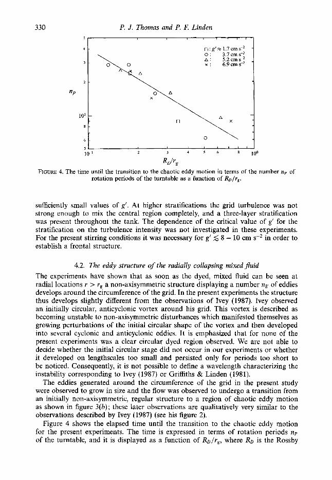
FIGURE 4. The time until the transition to the chaotic eddy motion in terms of the number rap of rotation periods of the turntable as a function of RD/rg.
sufficiently small values of g'. At higher stratifications the grid turbulence was not strong enough to mix the central region completely, and a three-layer stratification was present throughout the tank. The dependence of the critical value of g' for the stratification on the turbulence intensity was not investigated in these experiments. For the present stirring conditions it was necessary for g' 5 8 - 10 cm sP2 in order to establish a frontal structure.
4.2. The eddy structure of the radially collapsing mixed fluid The experiments have shown that as soon as the dyed, mixed fluid can be seen at radial locations r > rg a non-axisymmetric structure displaying a number nE of eddies develops around the circumference of the grid. In the present experiments the structure thus develops slightly different from the observations of Ivey (1987). Ivey observed an initially circular, anticyclonic vortex around his grid. This vortex is described as becoming unstable to non-axisymmetric disturbances which manifested themselves as growing perturbations of the initial circular shape of the vortex and then developed into several cyclonic and anticyclonic eddies. It is emphasized that for none of the present experiments was a clear circular dyed region observed. We are not able to decide whether the initial circular stage did not occur in our experiments or whether it developed on lengthscales too small and persisted only for periods too short to be noticed. Consequently, it is not possible to define a wavelength characterizing the instability corresponding to Ivey (1987) or Griffiths & Linden (1981).
The eddies generated around the circumference of the grid in the present study were observed to grow in size and the flow was observed to undergo a transition from an initially non-axisymmetric, regular structure to a region of chaotic eddy motion as shown in figure 3(b); these later observations are qualitatively very similar to the observations described by Ivey (1987) (see his figure 2).
Figure 4 shows the elapsed time until the transition to the chaotic eddy motion for the present experiments. The time is expressed in terms of rotation periods np of the turntable, and it is displayed as a function of RD/r,, where RD is the Rossby
A laboratory simulation of mixing across tidal fronts
C " " ' I " ' I " " ' - I 331
0 0
A
X
I : g' z 1.7 cm s - ~ o : 3.7 c m s 8 A : 5.2 cm s - ~ x : 6 . 9 c m s 2
i
0 0.2 0.4 0.6 0.8
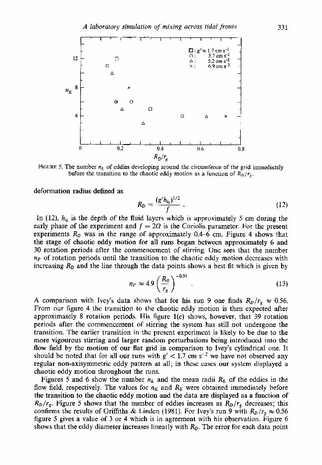
FIGURE 5. The number nE of eddies developing around the circumfence of the grid immediately before the transition to the chaotic eddy motion as a function of RD/rg.
W r g
deformation radius defined as
In (12), h, is the depth of the fluid layers which is approximately 5 cm during the early phase of the experiment and f = 252 is the Coriolis parameter. For the present experiments RD was in the range of approximately 0.4-6 cm. Figure 4 shows that the stage of chaotic eddy motion for all runs began between approximately 6 and 30 rotation periods after the commencement of stirring. One sees that the number np of rotation periods until the transition to the chaotic eddy motion decreases with increasing RD and the line through the data points shows a best fit which is given by
-0.91
n p w4.9 (') .
A comparison with Ivey's data shows that for his run 9 one finds RD/rg NN 0.56. From our figure 4 the transition to the chaotic eddy motion is then expected after approximately 8 rotation periods. His figure l(c) shows, however, that 39 rotation periods after the commencement of stirring the system has still not undergone the transition. The earlier transition in the present experiment is likely to be due to the more vigourous stirring and larger random perturbations being introduced into the flow field by the motion of our flat grid in comparison to Ivey's cylindrical one. It should be noted that for all our runs with g' < 1.7 cm s - ~ we have not observed any regular non-axisymmetric eddy pattern at all; in these cases our system displayed a chaotic eddy motion throughout the runs.
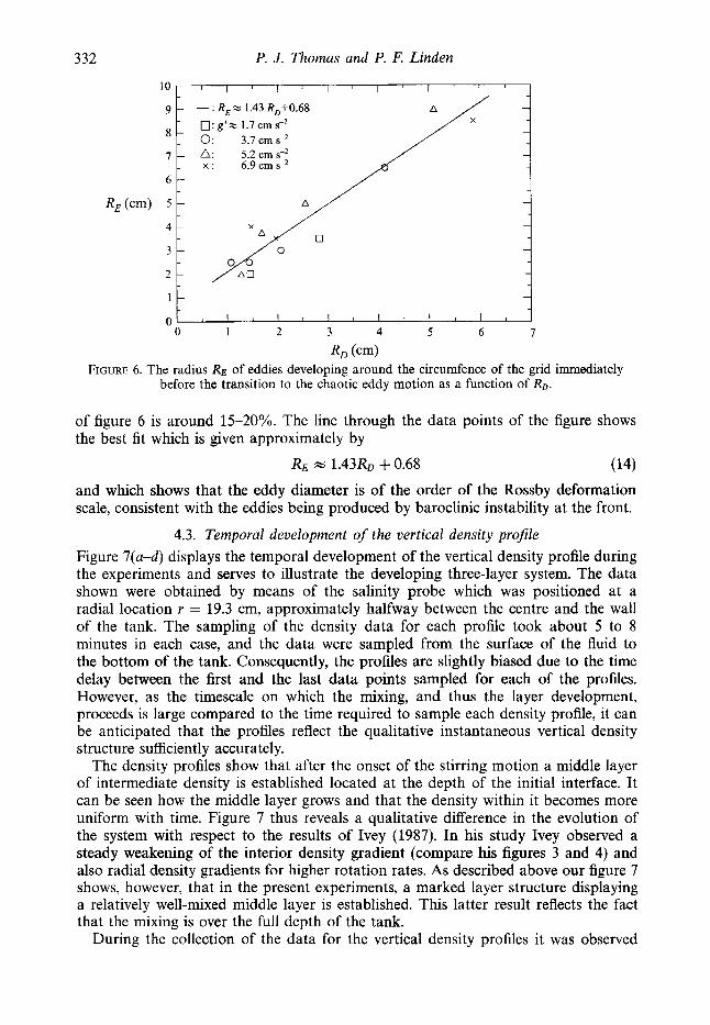
Figures 5 and 6 show the number nE and the mean radii RE of the eddies in the flow field, respectively. The values for nE and RE were obtained immediately before the transition to the chaotic eddy motion and the data are displayed as a function of RD/r,. Figure 5 shows that the number of eddies increases as RD/rE decreases; this confirms the results of Griffiths & Linden (1981). For Ivey's run 9 with RD/r , NN 0.56 figure 5 gives a value of 3 or 4 which is in agreement with his observation. Figure 6 shows that the eddy diameter increases linearly with RD. The error for each data point
332 P. J . Thomas and P. F. Linden
A
0: g'- 1.7 cm s?
A
0 l 1 l I I I I I I I l I
0 1 2 3 4 5 6 I
FIGURE 6. The radius RE of eddies developing around the circumfence of the grid immediately before the transition to the chaotic eddy motion as a function of RD.
R, (4
of figure 6 is around 15-20%. The line through the data points of the figure shows the best fit which is given approximately by
RE 1.43RD +0.68 ( 14) and which shows that the eddy diameter is of the order of the Rossby deformation scale, consistent with the eddies being produced by baroclinic instability at the front.
4.3. Temporal development of the vertical density profile Figure 7(a-d) displays the temporal development of the vertical density profile during the experiments and serves to illustrate the developing three-layer system. The data shown were obtained by means of the salinity probe which was positioned at a radial location Y = 19.3 cm, approximately halfway between the centre and the wall of the tank. The sampling of the density data for each profile took about 5 to 8 minutes in each case, and the data were sampled from the surface of the fluid to the bottom of the tank. Consequently, the profiles are slightly biased due to the time delay between the first and the last data points sampled for each of the profiles. However, as the timescale on which the mixing, and thus the layer development, proceeds is large compared to the time required to sample each density profile, it can be anticipated that the profiles reflect the qualitative instantaneous vertical density structure sufficiently accurately.
The density profiles show that after the onset of the stirring motion a middle layer of intermediate density is established located at the depth of the initial interface. It can be seen how the middle layer grows and that the density within it becomes more uniform with time. Figure 7 thus reveals a qualitative difference in the evolution of the system with respect to the results of Ivey (1987). In his study Ivey observed a steady weakening of the interior density gradient (compare his figures 3 and 4) and also radial density gradients for higher rotation rates. As described above our figure 7 shows, however, that in the present experiments, a marked layer structure displaying a relatively well-mixed middle layer is established. This latter result reflects the fact that the mixing is over the full depth of the tank.
During the collection of the data for the vertical density profiles it was observed
A laboratory simulation of mixing across tidal fronts 333
2 - .E:
- 6 -
10
8
8
8
4 1 , 2 , , , , * * , , ; w 1 8 t , j 0
1.000 1.001 1.002
P (g cm-3>
lo 8 0
2 :I 8
8 8 8 8
8
(b) i 8
0 I ' I ' I ' I , I ' I ' 1 ' .
1.000 1.001 1.002
10 -
8 -
6 -
4 -
2 -
8 8
8
8
8
8
8
8 8
1.000 1.001 1.002
P (g cm-3> FIGURE 7. Vertical density profiles at a radial position r = 19.3 cm from the centre of the tank at different times during a run of the experiment with SZ = 1.5 rad s-l and g' = 3.5 cm s-*: (a) t = 0 min, (b) t = 16 min (approximately 229 rotation periods), (c) t = 35 min (approximately 501 rotation periods), ( d ) t = 113 min (approximately 1619 rotation periods).
o ' ; t ' l ' l ' l i ' ' l ' ' 0.04 0.08 0.12
AP4 PI -PJ
FIGURE 8. Non-dimensional amplitude ApI(p1- p2) of the oscillation of the density values obtained from the salinity probe as a function of the height h above the bottom of the tank (displayed data points pertain to the vertical density profile of figure 7c).
that the readout values of the salinity probe at some vertical measuring positions oscillated around a mean value. The frequency of this oscillation was observed to be equal to the stirring frequency fg = 0.1 Hz of the grid and the amplitude Ap of the oscillation was found to vary with the height above the bottom of the tank. Figure 8 shows the data for the amplitude of this oscillation pertaining to the density profile of figure 7(c) . The figure shows the amplitude in terms of the density difference p1 - p2
334 P. J. Thomas and P. F. Linden
. . . . . . . .. .
1.001 . . -.
.. : .... :-.? . .... C -
0 1000 2000 3000 4000 5000
t (s) FIGURE 9. Temporal development of the fluid density at a radial position of r = 19.3 cm in a height h = 8 cm above the bottom of the tank for a run of the experiment with D = 0.25 rad s-l and g' = 9.6 cm s-'.
between the fluid of the bottom and the top layers. It can be seen that the data display two distinct maxima for the amplitude Ap of the oscillation at heights of h NN 3 cm and h NN 8 cm. A comparison with the vertical density profile in figure 7(c) shows that the positions of the two maxima correspond to regions of large density gradients in the transition region between the mixed and the upper fresh fluid layers, and between the mixed and the lower dense fluid layers respectively. Hence, the observed oscillation reflects internal wave motions of the layer interfaces excited and sustained by the oscillation of the grid.
Figure 9 shows the temporal variation of the density at a fixed position in the tank. The salinity probe was located at a radial position r = 19.3 cm at a height h = 8 cm above the bottom of the tank. It can be seen that the first noticeable change of the density at this location within the tank is registered approximately 500 s (equivalent to approximately 20 rotation periods) after the grid oscillation is initiated. For times t 2 500 s the mean density increases approximately linearly until it reaches a final constant value after around 4500 s (equivalent to approximately 180 rotation periods). This final value corresponds to the mean density value obtained from the bottom- and the top-layer fluid densities and represents the state of the fluid being well mixed. The linear trend up to this time results from the continual mixing of the three-layer system at roughly the same rates for the bottom- and the top-layer entrainment. The data points display an oscillation of the numeric value of the density around its mean value for times 500 s 5 t 5 4500 s. This oscillation of the density values was observed for all the runs in which the density was monitored at a fixed location within the tank. The oscillation was in all cases observed to occur on oscillation periods of several hundred seconds and the amplitude was found to be of the order of around 0.1 - 0.2 times the total density increase at the measuring position. The oscillation persists until the fluid at the measuring location reaches its final constant density value. It thus appears that this oscillation also reflects some baroclinic internal wave mode sustained throughout the runs of the experiment.
A laboratory simulation of mixing across tidal fronts 335
5
I
3
10-1
U
4 t * 1
'.. 0 0
0 2000 4000 6000 8000 t*
RGURE 10. Non-dimensional height h; of the bottom (a) and top ( b ) layers as a function of the non-dimensional time t' for g' = 1.77 cm sP2 and various values of 0.
4.4. Meanflow velocity across the bottom and top fronts at later stages Figures lO(a), and 10(b) display some typical experimental data for the non-dimensional layer heights hf as a function of the time t' for the later stages of the experiment after the full three-layer system has been established. The data were obtained for a constant value of g' and various values of 52 as is indicated in the legend of the figure. The layer height is plotted on a logarithmic scale and it can be seen that the experimental data are in all cases well represented by approximations as straight lines. This is consistent with the assumption of constant mean cross-front flow velocities of $3.2 (see (10)) and supports the theoretical considerations made there. A qualitative result immediately revealed by a comparison of the corresponding data sets of figures 10(a) and 10(b) is that the mean cross-front flow velocity across the top front is somewhat larger than the velocity across the bottom front.
Appropriate least-squares fits to the data points according to equation (10) yield values for the parameters pi. Figures 11 and 12 summarize the values obtained for the pi for all runs of the experiment. Figure ll(a,b) displays pi as a function of the non-dimensional rotation rate of the turntable which is expressed as Q/Q, It can be seen that f i t , and hence the two mean cross-front flow velocities, decrease with an increasing rotation rate. Analysis of the data in figure ll(a,b) yields for the
i I I 100 3 4 5 6 2 3
FIGURE 11. The pi for the flow across the bottom (a) and the top ( b ) fronts for various values of g' as a function of the non-dimensional rotation rate 62/6&.
bottom front -0.50+0.08
P I X ( $ ) 7
and for the top front -0.51+0.14
(15b)
Figure 12(a,b) displays the Pi as a function of the relative density difference g'/g between the fluids in the two layers. It can be seen that pi increases with increasing g ' / g , and best fits to the data yield for the bottom front
10-3
5 -
PI 2 -
10-4
5 -
337
I
- (a) 0 ........ i R=0.25 rad Q-'
: 0.5 rad s-l ____. .. . . @... - : 1.0 rad s-I .....
Figure 13(a,b) summarizes the above results for both of the pi. Figure 13(a) shows that the data obtained for collapse on a straight line approximated by
Figure 13(b) shows that the data obtained for P2 collapse on a straight line approxi- mated by
p2 m 0.004946 ($)-'"' (5)0'3y .
338 P. J. Thomas and P. F. Linden
10 ~ 1 ~ ~ " ' " I ' ~ ' " l ' ~ '
- (b) -
8 - - - -
6 - - 6 - x - -
-?
4 - - - -
2 - - - -
1 1 1 1 1 1 1 1 1 ~ I I I I I I I ~
FIGURE 13. fronts.
A comparison of equations (17) and (18) shows that, within the margin of error indicated in (15) and (16) , the functional relationships in the two expressions are essentially the same for the top and the bottom layers. This result reflects the symmetric nature of the stirring and also indicates that the dynamics in the vicinity of the bottom and the top fronts are similar to each other. Nevertheless, the multiplicative constant in equation (18) for the top layer is larger by a factor of about 3 than the corresponding constant for the bottom layer of equation (17). The mean cross-front flow velocity is thus larger for the top front than for the bottom front as had already been noted above during the discussion of the data of figure 10. This result appears to reflect the different boundary conditions in the vicinity of the two fronts, i.e. free surface for the top front and solid bottom for the bottom front. Equations (17) and (18) express one of the main results of this study, namely that rotation decreases and buoyancy increases the mean cross-front flow velocities.
Assuming that the functional relationships of equations (17) and (18) are indeed
A laboratory simulation of mixing across tidal fronts
I I I I I
X X
X
X X
X
X
339
X
X
O O A x . n=Orads-' X 0 0.5 radsd 0
0 : 1.0 rad s-I 0: lSrads-'
0 *: 2.0rads-'
o u /I
2 5 2 5 10' 101 103
t (s) FIGURE 14. The distance Rp - rg of the front of the spreading patch from the edge of the grid as a
function of the time t for the experiments with g' = 3.5 cm sP2.
the same for the bottom and the top fronts one can replace the exponents by their respective mean values. This yields as the final result
- (t)-0.51 (f) 0.34 % C i ( ! J 2 ( f > 113 >
with c1 = 0.001557 and c2 = 0.004946. From (8) and (11) the dependence of the mean cross-front flow velocities across the bottom and the top fronts on the rotation rate of the turntable and the strength of the stratification can thus be expressed as
4.5. The Froude number associated with the radial collapse of the mixedfluid regime
In $3.1 it was shown that the edge of the spreading mixed fluid regime is expected to propagate radially outwards according to t3j4. Figure 14 shows a selection of experimental data obtained for the size of the spreading patch as a function of time t. In order to account for the presence of the grid in the centre of the tank the ordinate of figure 14 displays the distance Rp - rg which the edge of the spreading patch has travelled away from the edge of the grid. Figure 14 displays the data points in a double logarithmic representation. The figure shows that the data points can be sufficiently well approximated by straight lines, which indicates a power law relationship between the size of the patch and the time t . The dotted line in the upper left-hand corner of the figure represents a time dependence corresponding to t3I4, for comparison. From the data of all 25 runs of the experiments where the size of the spreading patch was recorded from above the turntable a mean time de- pendence was obtained as t0.73*0.17. This result supports the theoretical considerations of $3.1.
With (6 ) and (20) it is now possible to obtain an estimate for the value of the
340 P. J. Thomas and P. F. Linden
Froude number F associated with the radial collapse of the mixed fluid regime. With equation ( 6 ) one obtains
Continuity requires that the total volume flux into the mixed region is equal to the volume flux 4 radially outwards which can be written as
4 = 1411 + 1421 >
where q1 and q2 represent the volume flux contributions from the bottom and the top layers, respectively. With respect to figure 2 and the discussion of $4.1 it can be assumed that the fluid from each of the two layers enters the mixed regime across the wall of cylindrical regions with a radius rg . If the heights of these cylinders are denoted hi then (22) can be written as
(23)
The values of hi are not readily determined from the experiments, but the maximum heights are the initial layer heights hi, w 5 cm. For this maximum height and constant cross-front flow velocities the contributions 41 and 42 are largest. Hence, with respect to expression (21), this results in an estimate for a lower limit of the Froude number F. By introducing (20) together with (19) in equation (23) one then obtains
(22)
4 = 2nrg(h11u11 + fizlu2l) .
With (24) equation (21) becomes
Figure 15 shows the values of F obtained according to (25) for the data of the runs of the experiment displayed in figure 14. It can be seen that the Froude number associated with the radial spread of the mixed regime is in the range of 0.005 5 F 5 0.035 and that it is approximately constant throughout each run of the experiment. Its numerical value is affected by the rotation of the system: it decreases with an increasing rotation rate of the turntable. These results support our assumptions of $3.1 concerning F. It is emphasized again that the values for the Froude number displayed in figure 15 are based on (23) where the fii were taken as the initial layer heights h, such that the values for F represent lower limits. The video recordings suggest that the appropriate value for hi in (23) is in the range between ihio 5 f i i 5 ihb. Hence, with respect to (24) and (25) the actual numeric values of the Froude number are expected to be approximately 1.42 .2 times higher than those displayed in figure 15.
It is of interest to compare our values for the Froude number with those obtained by Holford (1994) in a different experimental arrangement, where a buoyant volume of fluid was allowed to collapse under the influence of gravity and rotation on the surface of a denser fluid. The buoyant volume of fluid was initially contained in a cylindrical tube located at the centre of a rotating tank filled with denser brine. The
A laboratory simulation of mixing across tidal fronts
0.041 I 1 r I I I I I I I I I I I I 1 I I 8 I
0: R=0.5rads-' 0: 1.Orads-' 0: 1.5 rads-'
1 F 0.02
341
c -I 1 1 1 1 1 1 1 1 1 ~ 1 1 1 1 1 1 1 1 1
0 0.2 0.4 0.6 0.8 1 .o
(+-g)4R-rg)
FIGURE 15. The Froude number F associated with the propagation of the radially collapsing mixed fluid regime during the early stages of the experiment as a function of the relative distance of the front of the regime from the edge of the grid. The data shown were obtained from runs of the experiment with g' = 3.5 cm s-' and for various values of a.
10-1
5
2
F 10-2
5
2
10-31 ; I I I I L I I l I I 10' 102 5
F, FIGURE 16. The non-rotational Froude number F as a function of the rotational Froude number F,.
buoyant fluid was allowed to collapse radially under the influence of gravity when the tube was withdrawn and the rate of spread of the patch was measured.
In order to characterize the effects of rotation we now define a rotational Froude number F, as
This parameter relates the size of the mixing region rg with the Rossby deformation radius RD given by (12). For large values of F,, the effect of rotation is important and baroclinic instability is expected (Griffiths & Linden 1981 ; Holford 1994). For small
342 P. J . Thomas and P. F. Linden
values of F,, the patch spreads under the influence of gravity, only weakly modified by rotation. Figure 16 displays the non-rotational Froude number F as a function of F,. The values of F in figure 16 are the mean values determined for the data of figure 15 and for the corresponding similar plots not included here for the other values of g’. Figure 16 shows that the data for F for all the runs of the experiment collapse on a straight line in a double logarithmic representation. The data can be approximated by a least-squares fit given by
F = 0.036F;-0.32 . (27)
F cc . (28)
This result is in reasonable agreement with Holford (1994) who finds
Our individual data sets for the various values of g’ yield relations F cc F,“ with values of m = -0.20,-0.54,-0.47,-0.32,-0.44 for g’ = 0.6,1.7,3.7,5.2,6.9 cm s-*, respectively. These individual values for m indicate that the agreement of our data with (28) is actually closer than one might conclude from (27), and that our relatively low value of -0.32 for the exponent in (27) is caused by a few data points for the runs with g’ = 0.6 cm s - ~ and g’ = 5.2 cm sP2.
5. Conclusions In this study it is shown, for the first time, that it is possible to simulate a stationary
front in a region with an inhomogeneous turbulence field in the laboratory. We have experimentally determined the fluid exchange across the front and determined its dependence on the rotation rate and the strength of the stratification. We have described theoretically the cross-front fluid exchange by means of a constant (in time) mean cross-front flow velocity. Our main results, expressed by (19) and (20), concerning this cross-front flow velocity are that it decreases with an increasing rotation rate and that it increases with an increasing density anomaly across the front.
A comparison of our present results with the results of Ivey (1987) shows that the mechanisms controlling the horizontal cross-front fluid exchange and the redistribu- tion of the fluid over the mixed fluid regime are different from those mechanisms controlling vertical boundary mixing. In contrast to our results, Ivey showed that the vertical boundary mixing does not depend on the rotation rate. He also ob- served a steady weakening of the interior density stratification of his system with radial density gradients for higher rotation rates. In the present study, however, a marked development of a layer structure with a relatively well mixed middle layer was observed.
The cross-frontal mixing process in the present experiment is, therefore, a horizontal exchange of fluid from the stratified, non-turbulent side of the front into the well mixed region. This exchange is driven by baroclinic processes at a rate determined by the interplay of stratification and rotation. The presence of eddies on the scale of the deformation radius is a further indication of the baroclinic nature of the flow. A similar picture was described by Griffiths & Hopfinger (1984) for the spreading of a front into non-turbulent surroundings, and we find that similar dynamics is relevant at a stationary front. In our experiments the turbulence is strong enough to keep the central region vertically mixed, and the exchange is governed by the rate at which fluid from the stratified fluid can enter. This rate is set by a rotational Froude number
A laboratory simulation of mixing across tidal fronts 343
F,, and we show that the data collapse onto a single curve, determined only by the value of F,..
Our laboratory simulation of the mixing process necessarily represents a simplified approximation of the much more complex dynamics in the ocean. The laboratory study described by us identifies how the cross-front mixing process depends on the strength of the density anomaly across the front and the rate of rotation of the system. Our study does not take into account possible influences of other mechanisms which are present in the ocean. These influences are for instance a varying intensity of the turbulence due to the changing amplitude of the tidal current over the spring-neap cycle, wind-driven cross-frontal transfer and the ocean's bottom topography. Such other mechanisms will necessarily subsequently have to be considered separately in future studies. Nevertheless, the rate of rotation of the system and the strength of the density anomaly across the front are, as we have shown, two important factors involved in the cross-front mixing process. We believe that a dynamical balance similar to that present in our laboratory simulation exists and governs the dynamics in a shelf-sea front. We will now extrapolate our laboratory results to oceanographic conditions to obtain an estimate of the cross-front mixing velocity for a coastal front and to compare our laboratory results with field data.
One example of a tidally controlled front is found off Flamborough Head in the North Sea. The stronger tidal currents in the shallower water of the southern North Sea keep the water column well mixed throughout the year, but in the summer a stratification builds up in the north. The front tends to follow the depth contours, and extends out from the English coast at about 53.8" N splitting into two branches. The front is visible on satellite infra-red images of the sea surface which also show instabilities on the front with a wavelength of about 10 km, which is comparable with the Rossby deformation radius. This front was the subject of a number of intensive studies during the UK North Sea Project and the results of these studies are summarized in Hill et al. (1993).
Measurements of the velocity and density structure of the front were made and as expected the density structures on the two sides of the front are very different. A mean along-front flow was observed in approximate balance with the cross-front density structure. This flow advects fluid away from the English coast into the North Sea, and the front acts as a barrier to exchanges between the southern and northern North Sea. Mixing across the front, therefore, controls these exchanges and estimates of horizontal eddy diffusivities were made from single-particle statistics of trajectories of Decca-Argos buoys released near the front. Both the along-front and cross-front diffusivities were estimated to be about 80 m2 s-l , with associated Lagrangian lengthscales of about 1 km and timescales of 5 - 9 h.
The cross-front mixing velocity obtained in the present experiments can be scaled to give an estimate for the Flamborough Head front. The rotational Froude number is O( l), and so using (2) and (27) with h = 50 m, g' = m sP2 we obtain a cross-front entrainment velocity of about 3 cm s-'. The horizontal diffusivity K = u RD, where RD is the deformation radius ( m 4 km) which sets the scale of baroclinic eddies. These values give K = 120 m2 s-l which is encouragingly close to the estimates made from the direct oceanographic measurements.
It should be noted that the values obtained here are less than those measured in laboratory experiments which do not include turbulence near the front. The scaling given by Griffiths & Hopfinger (1984) based on baroclinic eddy transfers across a front in the absence of small-scale turbulence gives significantly higher values for the eddy diffusivity. We conclude, therefore, that baroclinic transfer processes across
344 P. J. Thomas and P. F. Linden
fronts, while they are the controlling mechanisms for cross-frontal mixing, are strongly modified by turbulence. The details of exactly how baroclinic instability is modified by background turbulence is a subject which deserves further study.
This work was supported by a grant from the Natural Environment Research Council.
REFERENCES
DALZIEL, S. 1994 Diglmage, Image Processing for Fluid Mechanics, System Overview. Cambridge
FERNANDO, H. J. S. 1991 Turbulent mixing in stratified fluids. Ann. Rev. Fluid Mech. 23, 455493. FLEURY, M., MORY, M., HOPFINGER, E. J. & AUCHERE, A. 1991 Effects of rotation on turbulent
GARRETT, C. J. R. & LODDER, J. W. 1981 Dynamical aspects of of shallow sea fronts. Phil. Trans.
GRIFFITHS, R. W. & HOPFINGER, E. J. 1984 The structure of mesoscale turbulence and horizontal
GRIFFITHS, R. W. & LINDEN, P. F. 1981 The stability of vortices in a rotating, stratified fluid. J.
HILL, A. E., JAMES, I. D., LINDEN, P. F. et al. 1993 Dynamics of tidal mixing fronts in the North
HOLFORD, J. M. 1994 The evolution of a front. PhD thesis, University of Cambridge, UK. IWY, G. N. 1987 Boundary mixing in a rotating, stratified fluid. J. Fluid Mech. 183, 25-44. JAMES, I. D. 1983 A three-dimensional model of shallow-sea fronts. In North Sea Dynamics (ed. J.
JAMES, I. D. 1990 Numerical modelling of density-driven circulation in shelf seas. In Modelling
LE F~VRE, J. 1986 Aspects of the biology of frontal systems. Adv. Mar. Biol. 23, 164299. LINDEN, P. F. 1991 Dynamics of eddies and fronts. In Proc. Enrico Fermi Summer School on ‘Nonlinear
MUNK, W. 1966 Abyssal recipes. Deep-sea Res. 13, 707-730. PINGREE, R. D. 1978 Cyclonic eddies and cross-frontal mixing. J. Mar. Biol. Assoc. UK 58,955-963. PINGREE, R. D. 1979 Baroclinic eddies bordering the Celtic Sea in late summer. J. Mar. Biol. Assoc.
PINGREE, R. D. & GRIFFITHS, D. K. 1978 Tidal fronts on the shelf seas around the British Isles. J .
Environmental Research Consultants Ltd., Cambridge, UK.
mixing across a density interface. J . Fluid Mech. 223, 165-191.
R . SOC. Lond. A 302, 563-581.
spreading at ocean fronts. Deep-sea Res. 31, 245-269.
Fluid Mech. 105, 283-316.
Sea. Phil. Trans. R. SOC. Lond. A 343, 431-446.
Siindermann & W. Lenz). Springer-Verlag.
Marine Systems, vol. I1 (ed. A. M. Davies), pp. 345-372. CRC Press.