32
A novel design of heat sink with PCM for electronics cooling Maciej Jaworski, Roman Domański Institute of Heat Engineering, Warsaw University of Technology
A novel design of heat sink with PCM for electronics cooling
Maciej Jaworski, Roman DomańskiInstitute of Heat Engineering, Warsaw University of Technology
10th International Conference on Thermal Energy Storage, 10th International Conference on Thermal Energy Storage, The Robert Stockton College of New Jersey, MayThe Robert Stockton College of New Jersey, May--June, 2006June, 2006
A novel design of heat sinkA novel design of heat sink with PCM for electronics coolingwith PCM for electronics cooling M.JaworskiM.Jaworski, , R.DomańskiR.Domański, , Warsaw University of TechnologyWarsaw University of Technology
Outline
• Introduction – PCM in electronics cooling devices• Novel design of heat sink for electronics cooling - description
• Basic characteristics of proposed design in normal mode of operation – Methods of analysis
– Results - basic properties of heat sink
• Thermal behavior of heat sink in transient thermal conditions– Mathematical and numerical model of heat transfer in transient
conditions,
– Thermal behavior of heat sink in case of fan accident• Conclusions
10th International Conference on Thermal Energy Storage, 10th International Conference on Thermal Energy Storage, The Robert Stockton College of New Jersey, MayThe Robert Stockton College of New Jersey, May--June, 2006June, 2006
A novel design of heat sinkA novel design of heat sink with PCM for electronics coolingwith PCM for electronics cooling M.JaworskiM.Jaworski, , R.DomańskiR.Domański, , Warsaw University of TechnologyWarsaw University of Technology
IntroductionCooling techniques for electronics devices
• Single phase flow: – natural convection air cooling, – forced convection air cooling, – liquid cooling (cold plates, jet impingement)
• Two-phase flow cooling systems: – pool boiling, – boiling in channels, (microchannels),– jet impingement with boiling, – spray cooling,
• Auxiliary heat transfer devices: – heat pipes, – thermoelectric modules
10th International Conference on Thermal Energy Storage, 10th International Conference on Thermal Energy Storage, The Robert Stockton College of New Jersey, MayThe Robert Stockton College of New Jersey, May--June, 2006June, 2006
A novel design of heat sinkA novel design of heat sink with PCM for electronics coolingwith PCM for electronics cooling M.JaworskiM.Jaworski, , R.DomańskiR.Domański, , Warsaw University of TechnologyWarsaw University of Technology
IntroductionPhase change materials (PCM) in electronics cooling application
• Heat sinks in portable (mobile) electronic devices: – palm pilots, – cellular phones,– personal digital assistants,
(devices seldom used for more than a few hours continuously at peak load and their idle time is typically long enough to solidify the molten PCM)
• PCM slurry as a heat transfer fluid in liquid cooling
• PCM as interface materialsprovide the best filling of micro-gaps in the case-heat sink interface while material is melted. Basically a mixture of organic binders (e.g. waxes) and fine particle ceramic fillers for thermal enhancement.

10th International Conference on Thermal Energy Storage, 10th International Conference on Thermal Energy Storage, The Robert Stockton College of New Jersey, MayThe Robert Stockton College of New Jersey, May--June, 2006June, 2006
A novel design of heat sinkA novel design of heat sink with PCM for electronics coolingwith PCM for electronics cooling M.JaworskiM.Jaworski, , R.DomańskiR.Domański, , Warsaw University of TechnologyWarsaw University of Technology
IntroductionExamples of PCM application in electronics cooling
1. Composite heat sinks (CHS),constructed using vertical array of fins, made of large latent heat capacity phase change materials (PCM) and highly conductive base material (BM)Akhilesh et al. / International Journal of Heat and Mass Transfer 48 (2005) 2759–2770
2. Heat storage unit containing PCMfor cooling of portable electronicsF.L. Tan, C.P. Tso / Applied Thermal Engineering 24 (2004) 159–169
3. PCM slurry as a heat transfer fluid in liquid cooling: paraffin (C22H46) + water + emilsifier, mass fraction of the paraffin slurry from 2,5 to 7,5%, K. Cho, M. Choi, Heat and Mass Transfer 36 (2000), pp. 29-36

10th International Conference on Thermal Energy Storage, 10th International Conference on Thermal Energy Storage, The Robert Stockton College of New Jersey, MayThe Robert Stockton College of New Jersey, May--June, 2006June, 2006
A novel design of heat sinkA novel design of heat sink with PCM for electronics coolingwith PCM for electronics cooling M.JaworskiM.Jaworski, , R.DomańskiR.Domański, , Warsaw University of TechnologyWarsaw University of Technology
Heat sink with PCM for electronics coolingProblems
• High efficiency of dissipation of heatlow total thermal resistance:– High heat transfer coefficient, – Large heat transfer surface area,
• Efficient transfer of heat to PCMincorporation of PCM in heat sink structure
10th International Conference on Thermal Energy Storage, 10th International Conference on Thermal Energy Storage, The Robert Stockton College of New Jersey, MayThe Robert Stockton College of New Jersey, May--June, 2006June, 2006
A novel design of heat sinkA novel design of heat sink with PCM for electronics coolingwith PCM for electronics cooling M.JaworskiM.Jaworski, , R.DomańskiR.Domański, , Warsaw University of TechnologyWarsaw University of Technology
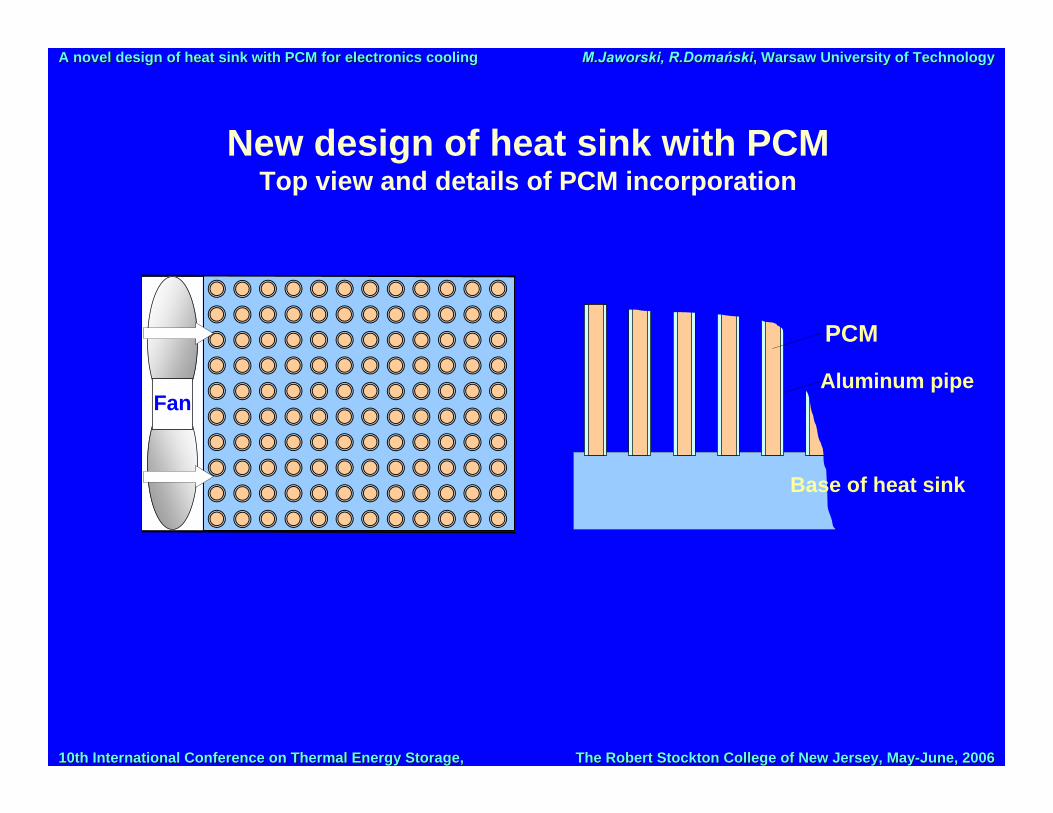
New design of heat sink with PCMTop view and details of PCM incorporation
Fan
Base of heat sink
Aluminum pipe
PCM

10th International Conference on Thermal Energy Storage, 10th International Conference on Thermal Energy Storage, The Robert Stockton College of New Jersey, MayThe Robert Stockton College of New Jersey, May--June, 2006June, 2006
A novel design of heat sinkA novel design of heat sink with PCM for electronics coolingwith PCM for electronics cooling M.JaworskiM.Jaworski, , R.DomańskiR.Domański, , Warsaw University of TechnologyWarsaw University of Technology
New design of heat sink with PCMDetails
External walls Channel for air flow
10th International Conference on Thermal Energy Storage, 10th International Conference on Thermal Energy Storage, The Robert Stockton College of New Jersey, MayThe Robert Stockton College of New Jersey, May--June, 2006June, 2006
A novel design of heat sinkA novel design of heat sink with PCM for electronics coolingwith PCM for electronics cooling M.JaworskiM.Jaworski, , R.DomańskiR.Domański, , Warsaw University of TechnologyWarsaw University of Technology
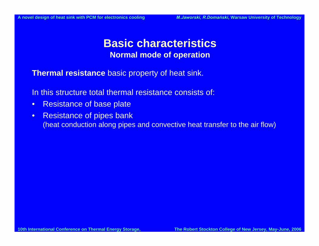
Basic characteristics Normal mode of operation
Thermal resistance basic property of heat sink.
In this structure total thermal resistance consists of:• Resistance of base plate • Resistance of pipes bank
(heat conduction along pipes and convective heat transfer to the air flow)
10th International Conference on Thermal Energy Storage, 10th International Conference on Thermal Energy Storage, The Robert Stockton College of New Jersey, MayThe Robert Stockton College of New Jersey, May--June, 2006June, 2006
A novel design of heat sinkA novel design of heat sink with PCM for electronics coolingwith PCM for electronics cooling M.JaworskiM.Jaworski, , R.DomańskiR.Domański, , Warsaw University of TechnologyWarsaw University of Technology
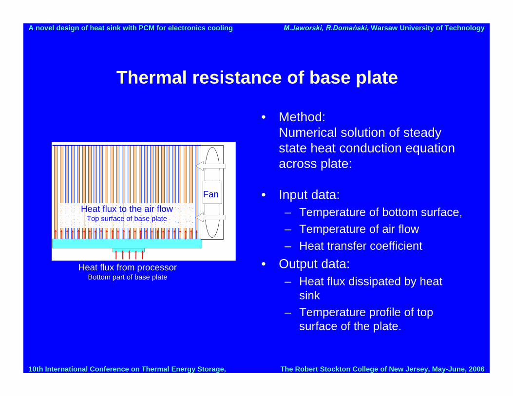
Thermal resistance of base plate
Fan
Heat flux from processorBottom part of base plate
Heat flux to the air flowTop surface of base plate
• Method:Numerical solution of steady state heat conduction equation across plate:
• Input data:– Temperature of bottom surface, – Temperature of air flow– Heat transfer coefficient
• Output data:– Heat flux dissipated by heat
sink– Temperature profile of top
surface of the plate.
10th International Conference on Thermal Energy Storage, 10th International Conference on Thermal Energy Storage, The Robert Stockton College of New Jersey, MayThe Robert Stockton College of New Jersey, May--June, 2006June, 2006
A novel design of heat sinkA novel design of heat sink with PCM for electronics coolingwith PCM for electronics cooling M.JaworskiM.Jaworski, , R.DomańskiR.Domański, , Warsaw University of TechnologyWarsaw University of Technology
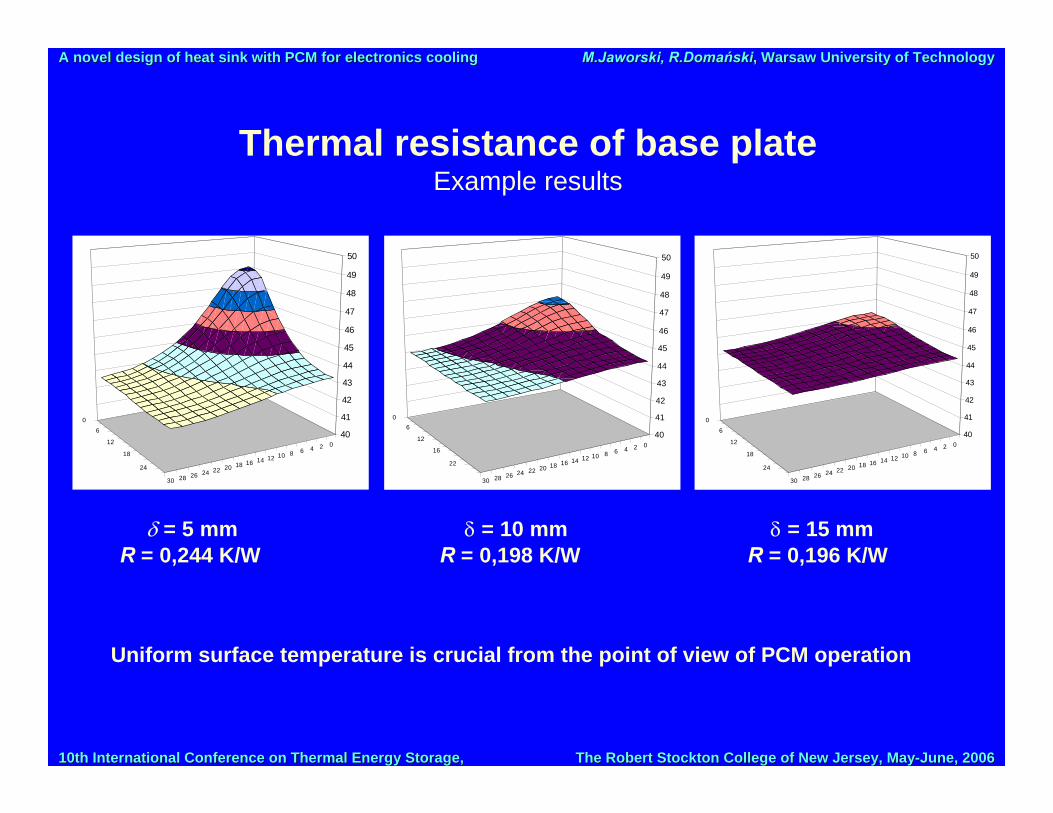
Thermal resistance of base plateExample results
024681012141618202224262830
0
6
12
18
24
40
41
42
43
44
45
46
47
48
49
50
024681012141618202224262830
06
12
16
22
40
41
42
43
44
45
46
47
48
49
50
024681012141618202224262830
0
6
12
18
24
40
41
42
43
44
45
46
47
48
49
50
δ = 5 mm δ = 10 mm δ = 15 mmR = 0,244 K/W R = 0,198 K/W R = 0,196 K/W
Uniform surface temperature is crucial from the point of view of PCM operation

10th International Conference on Thermal Energy Storage, 10th International Conference on Thermal Energy Storage, The Robert Stockton College of New Jersey, MayThe Robert Stockton College of New Jersey, May--June, 2006June, 2006
A novel design of heat sinkA novel design of heat sink with PCM for electronics coolingwith PCM for electronics cooling M.JaworskiM.Jaworski, , R.DomańskiR.Domański, , Warsaw University of TechnologyWarsaw University of Technology
Thermal resistance of base plateExample results – input data
• Dimensions of plate: 50×60 mm,• Dimensions of contact area – surface of processor: 10×10 mm, in the middle of the
plate’s lower surface,• Dimensions of pipes/fins: diameter 3 mm, thickness of the wall 0,2 mm, length 50
mm, s = 6 mm; efficiency of such pipe/fin equals to 0,27, • Boundary condition on the contact area – known, uniform temperature,• Boundary condition on the upper surface – third kind b.c.: know convective heat
transfer coefficient and air temperature. Effective heat transfer coefficient was determined from the formula heff = hπdlηfin/s2
which takes into account real heat transfer coefficient on the surface of pipes/fins, efficiency of fins, their dimensions and density of fins on the surface (s – distance between pipes), real heat transfer coefficient h = 180 W/(m2K), its effective value: 630 W/(m2K)
• Other surfaces were considered as adiabatic (heat transfer is so small that can be neglected).Material data (aluminum):
• k = 200 W/(m⋅K), ρ = 2800 kg/m3, cp = 880 J/(kg⋅K),
10th International Conference on Thermal Energy Storage, 10th International Conference on Thermal Energy Storage, The Robert Stockton College of New Jersey, MayThe Robert Stockton College of New Jersey, May--June, 2006June, 2006
A novel design of heat sinkA novel design of heat sink with PCM for electronics coolingwith PCM for electronics cooling M.JaworskiM.Jaworski, , R.DomańskiR.Domański, , Warsaw University of TechnologyWarsaw University of Technology
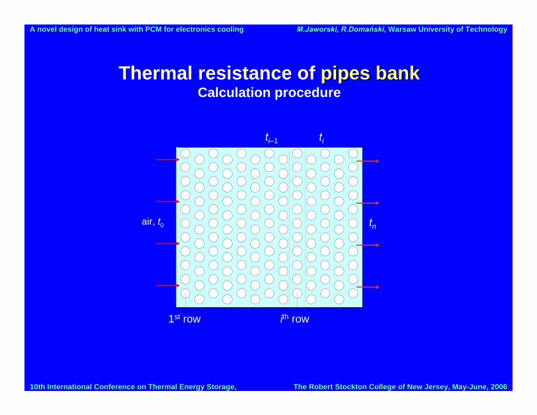
Thermal resistance of pipes bankpipes bankCalculation procedure
1st row ith row
ti–1 ti
air, t0 tn

10th International Conference on Thermal Energy Storage, 10th International Conference on Thermal Energy Storage, The Robert Stockton College of New Jersey, MayThe Robert Stockton College of New Jersey, May--June, 2006June, 2006
A novel design of heat sinkA novel design of heat sink with PCM for electronics coolingwith PCM for electronics cooling M.JaworskiM.Jaworski, , R.DomańskiR.Domański, , Warsaw University of TechnologyWarsaw University of Technology
Thermal resistance of pipes bankCalculation procedure
Thermal resistance for heat transfer along pipes and heat convection to the air flow:
QTTR b 0−
=
Total heat flux Q: ∑=
=n,i
iQQ1
Heat flux for i-th row of pipes
finibiii TTAhQ η)( 1−−=
Heat transfer coefficient:
i
,
w
nmmax
outi CCkdh
250
PrPrPrReNu ⎟⎟
⎠
⎞⎜⎜⎝
⎛==
Temperature increase of air flowing across i-th row is estimated from the energy balance
iiip QTTcm =− − )( 1&
Pipe/fin efficiency
mlml
fin)(tanh
=η ; ( )224
inout
out
ddkdhm−
=
10th International Conference on Thermal Energy Storage, 10th International Conference on Thermal Energy Storage, The Robert Stockton College of New Jersey, MayThe Robert Stockton College of New Jersey, May--June, 2006June, 2006
A novel design of heat sinkA novel design of heat sink with PCM for electronics coolingwith PCM for electronics cooling M.JaworskiM.Jaworski, , R.DomańskiR.Domański, , Warsaw University of TechnologyWarsaw University of Technology
Thermal resistance of pipes bankExample results
Thermal resistance of heat sinks with pipes of different wall thickness; diameter of pipes 3 mm
Internal diameter of pipes, din, mm
Thickness of pipe wall, δw, mm
Thermal resistance, R, K/W
2,6 0,2 0,538 2,4 0,3 0,463 2,2 0,4 0,415 2,0 0,5 0,385
Thermal resistance of heat sinks with different spacing between pipes s;
diameter of pipes 3 mm, thickness of the wall 0,2 mm Distance between
pipes, s, mm Total number
of pipes Heat transfer area,
cm2 Thermal resistance
R, K/W 6 80 (8×10) 377 0,538
5,4 99 (9×11) 467 0,426 4,8 120 (10×12) 565 0,345 4,2 154 (11×14) 726 0,270
10th International Conference on Thermal Energy Storage, 10th International Conference on Thermal Energy Storage, The Robert Stockton College of New Jersey, MayThe Robert Stockton College of New Jersey, May--June, 2006June, 2006
A novel design of heat sinkA novel design of heat sink with PCM for electronics coolingwith PCM for electronics cooling M.JaworskiM.Jaworski, , R.DomańskiR.Domański, , Warsaw University of TechnologyWarsaw University of Technology
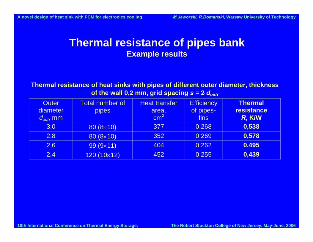
Thermal resistance of pipes bankExample results
Thermal resistance of heat sinks with pipes of different outer diameter, thickness of the wall 0,2 mm, grid spacing s = 2⋅dout,
Outer diameter dout, mm
Total number of pipes
Heat transfer area, cm2
Efficiency of pipes-
fins
Thermal resistance
R, K/W 3,0 80 (8×10) 377 0,268 0,538 2,8 80 (8×10) 352 0,269 0,578 2,6 99 (9×11) 404 0,262 0,495 2,4 120 (10×12) 452 0,255 0,439

10th International Conference on Thermal Energy Storage, 10th International Conference on Thermal Energy Storage, The Robert Stockton College of New Jersey, MayThe Robert Stockton College of New Jersey, May--June, 2006June, 2006
A novel design of heat sinkA novel design of heat sink with PCM for electronics coolingwith PCM for electronics cooling M.JaworskiM.Jaworski, , R.DomańskiR.Domański, , Warsaw University of TechnologyWarsaw University of Technology
Total thermal resistance of heat sinkExample results
Total thermal resistance of heat sinks with different base plates (pipe bank – 3/2,6 mm, s = 6 mm)
Thickness of base plate, mm
Max temperature difference on the
surface, K
Thermal resistance of base plate,
K/W
Total thermal resistance,
K/W 5 5,7 0,244 0,782 10 2,5 0,198 0,736 15 1,2 0,196 0,734
10th International Conference on Thermal Energy Storage, 10th International Conference on Thermal Energy Storage, The Robert Stockton College of New Jersey, MayThe Robert Stockton College of New Jersey, May--June, 2006June, 2006
A novel design of heat sinkA novel design of heat sink with PCM for electronics coolingwith PCM for electronics cooling M.JaworskiM.Jaworski, , R.DomańskiR.Domański, , Warsaw University of TechnologyWarsaw University of Technology
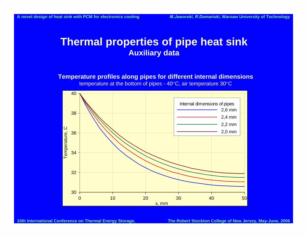
Thermal properties of pipe heat sink Auxiliary data
0 10 20 30 40 50x, mm
30
32
34
36
38
40
Tem
pera
ture
, C
Internal dimensions of pipes2,6 mm2,4 mm2,2 mm2,0 mm
Temperature profiles along pipes for different internal dimensionstemperature at the bottom of pipes - 40°C, air temperature 30°C
10th International Conference on Thermal Energy Storage, 10th International Conference on Thermal Energy Storage, The Robert Stockton College of New Jersey, MayThe Robert Stockton College of New Jersey, May--June, 2006June, 2006
A novel design of heat sinkA novel design of heat sink with PCM for electronics coolingwith PCM for electronics cooling M.JaworskiM.Jaworski, , R.DomańskiR.Domański, , Warsaw University of TechnologyWarsaw University of Technology
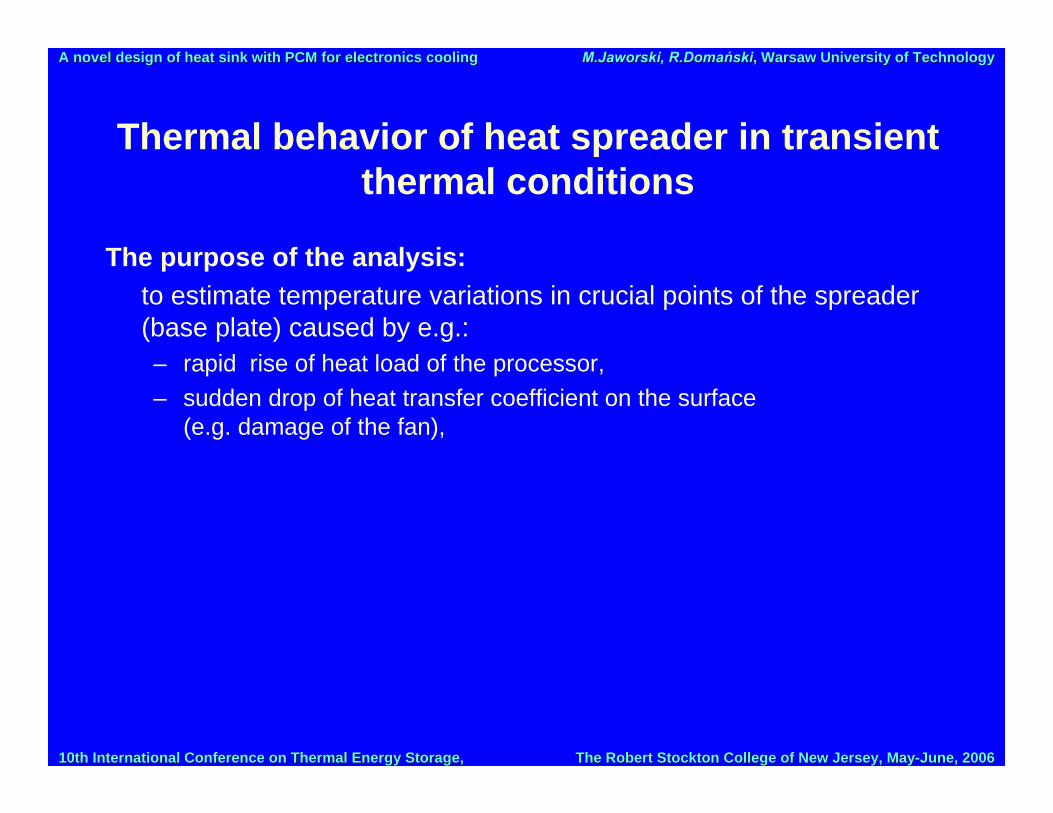
Thermal behavior of heat spreader in transient thermal conditions
The purpose of the analysis: to estimate temperature variations in crucial points of the spreader (base plate) caused by e.g.:– rapid rise of heat load of the processor, – sudden drop of heat transfer coefficient on the surface
(e.g. damage of the fan),

10th International Conference on Thermal Energy Storage, 10th International Conference on Thermal Energy Storage, The Robert Stockton College of New Jersey, MayThe Robert Stockton College of New Jersey, May--June, 2006June, 2006
A novel design of heat sinkA novel design of heat sink with PCM for electronics coolingwith PCM for electronics cooling M.JaworskiM.Jaworski, , R.DomańskiR.Domański, , Warsaw University of TechnologyWarsaw University of Technology
Physical model
Air;h, T∞
Liquid PCM
solid-liquidmoving interface
Solid PCM
aluminum pipe wall In normal operation mode – electronics work in stable conditions – excess heat is released to the ambient air through base plate and walls of pipes (high conductivity part of the spreader); PCM doesn't take part in heat transfer; however, it is heated to the same temperature as the wall at the same level (similar temperature profile along the axis)
In transient conditions – due to the change of temperature of the wall a part of dissipated heat is transferred to the PCM region causing heating and melting of this material.

10th International Conference on Thermal Energy Storage, 10th International Conference on Thermal Energy Storage, The Robert Stockton College of New Jersey, MayThe Robert Stockton College of New Jersey, May--June, 2006June, 2006
A novel design of heat sinkA novel design of heat sink with PCM for electronics coolingwith PCM for electronics cooling M.JaworskiM.Jaworski, , R.DomańskiR.Domański, , Warsaw University of TechnologyWarsaw University of Technology
Mathematical model
Heat conduction equation (in polar coordinate system (r, x))
⎥⎦
⎤⎢⎣
⎡∂∂
+⎟⎟⎠
⎞⎜⎜⎝
⎛∂∂
∂∂
=∂∂
2
21xT
rTr
rrkTc i
ipii τ
ρ
index i denotes different materials (aluminum or PCM) or phases (solid or liquid of PCM). Convective boundary condition on the surface of pipes
( )∞=
−=∂∂
− TrThrTk out
rrAl
out
)(
On the interfaces between metal and PCM boundary conditions of the fourth kind
PCM
PCMPCM
Al
AlAl r
Tkr
Tk∂
∂−=
∂∂
−
00 == ∂
∂−=
∂∂
−x
PCMPCM
x
AlAl x
Tx
T λλ

10th International Conference on Thermal Energy Storage, 10th International Conference on Thermal Energy Storage, The Robert Stockton College of New Jersey, MayThe Robert Stockton College of New Jersey, May--June, 2006June, 2006
A novel design of heat sinkA novel design of heat sink with PCM for electronics coolingwith PCM for electronics cooling M.JaworskiM.Jaworski, , R.DomańskiR.Domański, , Warsaw University of TechnologyWarsaw University of Technology
Mathematical modelInitial conditions
Heat transfer coefficient on the surface of pipes: 180 W/(m2K), Given temperature of air flow (30°C) Temperature profile along pipes
mLxLmTTTxT b cosh)(cosh)()( −
−+= ∞∞
Given temperature of the upper part of base plate (40°C) Heat flux dissipated to the air calculated for the above thermalconditions; this heat flux is set constant in subsequent calcu-lations – thermal behavior of the heat sink in changed condi-tions (changed heat transfer coefficient)

10th International Conference on Thermal Energy Storage, 10th International Conference on Thermal Energy Storage, The Robert Stockton College of New Jersey, MayThe Robert Stockton College of New Jersey, May--June, 2006June, 2006
A novel design of heat sinkA novel design of heat sink with PCM for electronics coolingwith PCM for electronics cooling M.JaworskiM.Jaworski, , R.DomańskiR.Domański, , Warsaw University of TechnologyWarsaw University of Technology
Numerical solution
• CVFDM with explicit integration over time
• 100×6 control volumes of ring shape
• Relation between enthalpy and temperature for the PCM
∆z
∆r
⎪⎪⎩
⎪⎪⎨
⎧
∆+>∆+−++∆−
∆+∆−∈∆
∆+−+∆−
∆−<
=
mmmmplmmmps
mmmm
mmmmmps
mmps
TTTTTTcCTTc
TTTTTT
TTTCTTc
TTTTc
TH
21for )()21(
)21;21(for 21
)21(
21for
)(
where: Cm – latent heat, ∆Tm – range of temperature in which melting occurs, cps and cpl – specific heats of solid and liquid PCM.

10th International Conference on Thermal Energy Storage, 10th International Conference on Thermal Energy Storage, The Robert Stockton College of New Jersey, MayThe Robert Stockton College of New Jersey, May--June, 2006June, 2006
A novel design of heat sinkA novel design of heat sink with PCM for electronics coolingwith PCM for electronics cooling M.JaworskiM.Jaworski, , R.DomańskiR.Domański, , Warsaw University of TechnologyWarsaw University of Technology
Phase change material
Lauric acid CH3(CH2)10COOH (fatty acid) – material which is considered as PCM in different energy storage applications, melting temperature fits the requirements of electronics cooling; material was tested experimentally in real radiator for electronics cooling.
Material properties – heat capacity measured by DSC technique (lauric acid of 99,5% purity made by Roth GmbH):
Melting point, °C 41,5 ± 1Latent heat, kJ/kg 178Specific heat of solid, kJ/(kg⋅K) 2,34Specific heat of liquid, kJ/(kg⋅K) 2,17Thermal conductivity, W/(m⋅K) 0,2Density, kg/m3 800
10th International Conference on Thermal Energy Storage, 10th International Conference on Thermal Energy Storage, The Robert Stockton College of New Jersey, MayThe Robert Stockton College of New Jersey, May--June, 2006June, 2006
A novel design of heat sinkA novel design of heat sink with PCM for electronics coolingwith PCM for electronics cooling M.JaworskiM.Jaworski, , R.DomańskiR.Domański, , Warsaw University of TechnologyWarsaw University of Technology
Results of numerical simulations
Temperature variations vs. time in different points of the pipe with PCM in transient conditions after sudden drop of heat transfer coefficient from 180 to 10 W/(m2⋅K)
0 30 60 90 120 150 180 210 240 270 300Time, s
30
40
50
60
70
80
90Te
mpe
ratu
re, C
Base of the pipe
Top of the pipe
PCM at different levels
Base of the pipe (no PCM)
10th International Conference on Thermal Energy Storage, 10th International Conference on Thermal Energy Storage, The Robert Stockton College of New Jersey, MayThe Robert Stockton College of New Jersey, May--June, 2006June, 2006
A novel design of heat sinkA novel design of heat sink with PCM for electronics coolingwith PCM for electronics cooling M.JaworskiM.Jaworski, , R.DomańskiR.Domański, , Warsaw University of TechnologyWarsaw University of Technology
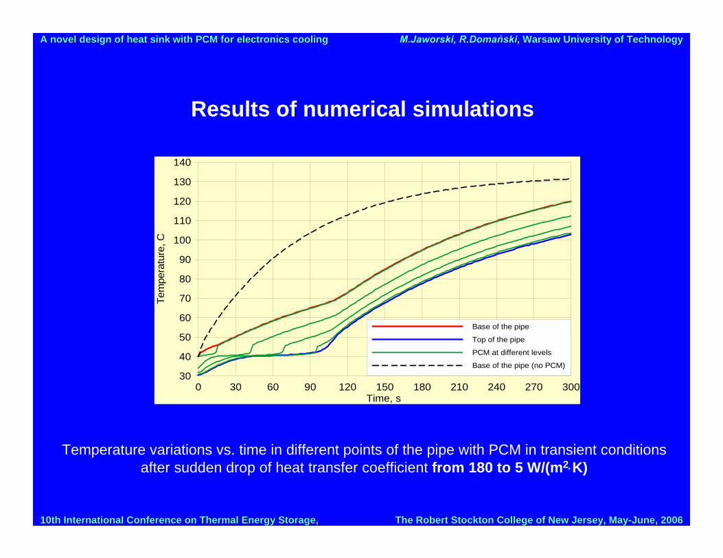
Results of numerical simulations
0 30 60 90 120 150 180 210 240 270 300Time, s
30
40
50
60
70
80
90
100
110
120
130
140Te
mpe
ratu
re, C
Base of the pipe
Top of the pipe
PCM at different levels
Base of the pipe (no PCM)
Temperature variations vs. time in different points of the pipe with PCM in transient conditions after sudden drop of heat transfer coefficient from 180 to 5 W/(m2⋅K)

10th International Conference on Thermal Energy Storage, 10th International Conference on Thermal Energy Storage, The Robert Stockton College of New Jersey, MayThe Robert Stockton College of New Jersey, May--June, 2006June, 2006
A novel design of heat sinkA novel design of heat sink with PCM for electronics coolingwith PCM for electronics cooling M.JaworskiM.Jaworski, , R.DomańskiR.Domański, , Warsaw University of TechnologyWarsaw University of Technology
Results of numerical simulations
0 30 60 90 120 150 180 210 240 270 300Time, s
30
40
50
60
70
80
90
100
110
120
130
140
Tem
pera
ture
, C
Base of the pipe
Top of the pipe
PCM at different levels
Base of the pipe (no PCM)
0 30 60 90 120 150 180 210 240 270 300Time, s
30
40
50
60
70
80
90
100
110
120
130
140
Tem
pera
ture
, C
Base of the pipe
Top of the pipe
PCM at different levels
Base of the pipe (no PCM)
Comparison of foregoing results:
• Distinct difference of maximum temperature,• Similar time of stabilization of temperature – the same amount of PCM, similar
thermal conditions on the boundary of PCM region

10th International Conference on Thermal Energy Storage, 10th International Conference on Thermal Energy Storage, The Robert Stockton College of New Jersey, MayThe Robert Stockton College of New Jersey, May--June, 2006June, 2006
A novel design of heat sinkA novel design of heat sink with PCM for electronics coolingwith PCM for electronics cooling M.JaworskiM.Jaworski, , R.DomańskiR.Domański, , Warsaw University of TechnologyWarsaw University of Technology
Results of numerical simulations
Temperature variations vs. time in selected points in the pipes of different diametersSolid lines – diameter of the pipe equals to 1,5 mm, dashed lines – 3 mm; thickness of the wall 0,2 mm; Differences in thermal performance are basically due to greater amount of PCM
in the spreader with 3 mm pipes
0 30 60 90 120 150 180 210 240 270 300Time, s
30
40
50
60
70
80
90
100
Tem
pera
ture
, C
base of the pipe with PCM (red lines)
PCM in the middle of the pipe (green lines)
base of the pipe without PCM (blue lines)
10th International Conference on Thermal Energy Storage, 10th International Conference on Thermal Energy Storage, The Robert Stockton College of New Jersey, MayThe Robert Stockton College of New Jersey, May--June, 2006June, 2006
A novel design of heat sinkA novel design of heat sink with PCM for electronics coolingwith PCM for electronics cooling M.JaworskiM.Jaworski, , R.DomańskiR.Domański, , Warsaw University of TechnologyWarsaw University of Technology
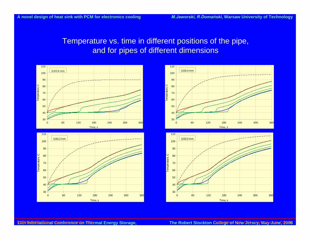
Temperature vs. time in different positions of the pipe, and for pipes of different dimensions
0 60 120 180 240 300 360
Time, s
30
40
50
60
70
80
90
100
110
Tem
pera
ture
, C
3,0/2,6 mm
0 60 120 180 240 300 360
Time, s
30
40
50
60
70
80
90
100
110
Tem
pera
ture
, C
3,0/2,4 mm
0 60 120 180 240 300 360
Time, s
30
40
50
60
70
80
90
100
110
Tem
pera
ture
, C
3,0/2,2 mm
EUROTHERM 82 Numerical Heat Transfer 2005 September 13-16, 2005, Gliwice-Cracow, Poland
0 60 120 180 240 300 360
Time, s
30
40
50
60
70
80
90
100
110
Tem
pera
ture
, C
3,0/2,0 mm
10th International Conference on Thermal Energy Storage, 10th International Conference on Thermal Energy Storage, The Robert Stockton College of New Jersey, MayThe Robert Stockton College of New Jersey, May--June, 2006June, 2006
A novel design of heat sinkA novel design of heat sink with PCM for electronics coolingwith PCM for electronics cooling M.JaworskiM.Jaworski, , R.DomańskiR.Domański, , Warsaw University of TechnologyWarsaw University of Technology
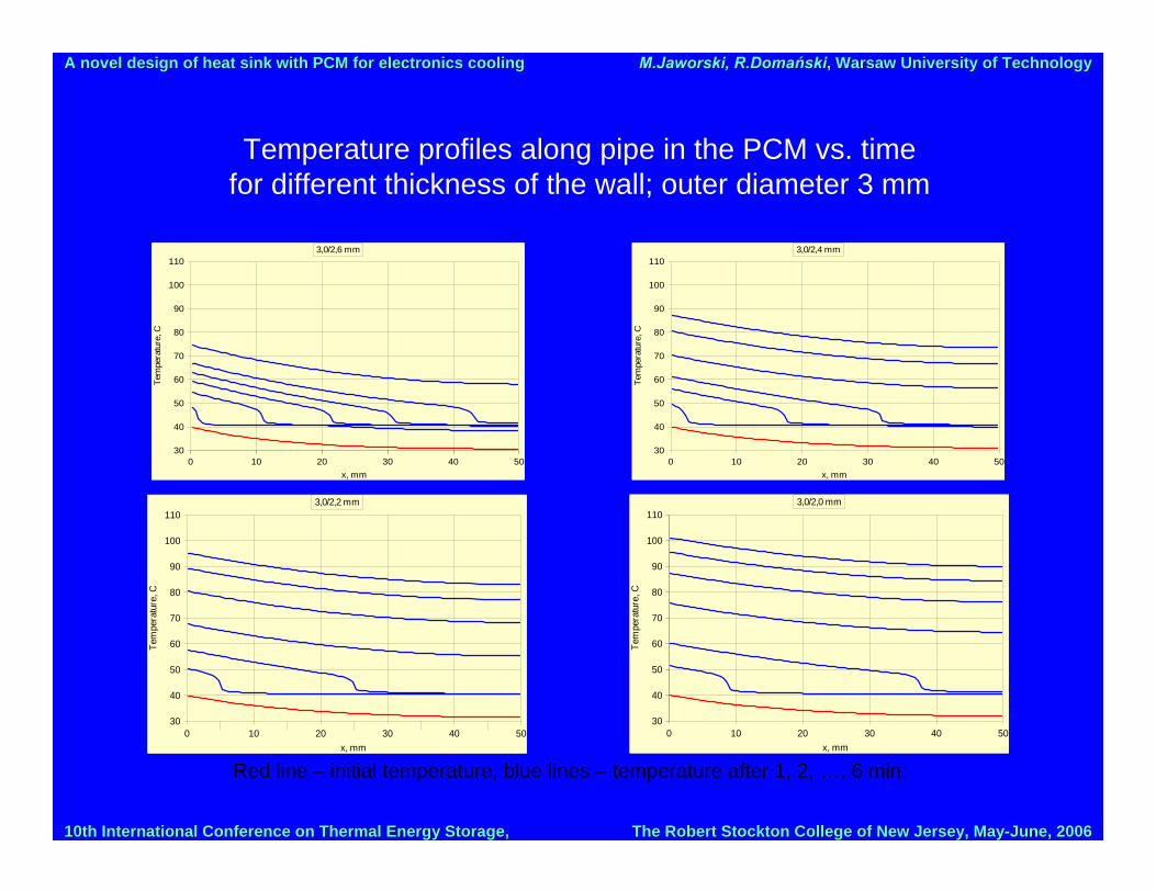
Temperature profiles along pipe in the PCM vs. timefor different thickness of the wall; outer diameter 3 mm
0 10 20 30 40 50x, mm
30
40
50
60
70
80
90
100
110
Tem
pera
ture
, C
3,0/2,2 mm
0 10 20 30 40 50x, mm
30
40
50
60
70
80
90
100
110
Tem
pera
ture
, C
3,0/2,4 mm
0 10 20 30 40 50x, mm
30
40
50
60
70
80
90
100
110
Tem
pera
ture
, C
3,0/2,6 mm
Red line – initial temperature, blue lines – temperature after 1, 2, …, 6 min;
0 10 20 30 40 50x, mm
30
40
50
60
70
80
90
100
110
Tem
pera
ture
, C
3,0/2,0 mm

10th International Conference on Thermal Energy Storage, 10th International Conference on Thermal Energy Storage, The Robert Stockton College of New Jersey, MayThe Robert Stockton College of New Jersey, May--June, 2006June, 2006
A novel design of heat sinkA novel design of heat sink with PCM for electronics coolingwith PCM for electronics cooling M.JaworskiM.Jaworski, , R.DomańskiR.Domański, , Warsaw University of TechnologyWarsaw University of Technology
Temperature profiles along aluminum pipe vs. timeas in the previous slide
Red line – initial temperature, blue lines – temperature after 1, 2, …, 6 min;
0 10 20 30 40 50x, mm
30
40
50
60
70
80
90
100
110
Tem
pera
ture
, C
3,0/2,6 mm
0 10 20 30 40 50x, mm
30
40
50
60
70
80
90
100
110
Tem
pera
ture
, C
3,0/2,4 mm
0 10 20 30 40 50x, mm
30
40
50
60
70
80
90
100
110
Tem
pera
ture
, C
3,0/2,2 mm
0 10 20 30 40 50x, mm
30
40
50
60
70
80
90
100
110
Tem
pera
ture
, C
3,0/2,0 mm

10th International Conference on Thermal Energy Storage, 10th International Conference on Thermal Energy Storage, The Robert Stockton College of New Jersey, MayThe Robert Stockton College of New Jersey, May--June, 2006June, 2006
A novel design of heat sinkA novel design of heat sink with PCM for electronics coolingwith PCM for electronics cooling M.JaworskiM.Jaworski, , R.DomańskiR.Domański, , Warsaw University of TechnologyWarsaw University of Technology
Conclusions
• Advantages of the cooling device:– high cooling efficiency in nominal conditions, due to high heat transfer
coefficient and relatively large area,
– potential to stabilize the temperature of the electronics device,– potential to protect the electronics from burning caused by rapid
changes (increase) in heat transfer rates,
have been proved theoretically
• Drawbacks of the device – rather complex structure and manufacturing


