A NOVEL SELF TUNING CONTROLLER DESIGN FOR UPFC AND STATCOM TO MINIMISE INTER HARMONIC OSCILLATIONS M.Dilip Kumar 1 , P.Sujatha 2 1 Associate Professor, 2 Professor, 1 Priyadarshini Institute of Technology , Tirupati -517501,India 2 JNTUCEA, Ananthapuramu-515502,India July 11, 2018 Abstract Power system planners have come to rely on FACTS de- vices to overcome several operational limitations in terms of thermal stability, voltage stability and other limitations of- fered by transmission lines. The FACTS devices are capable of controlling the power flow alternating voltage magnitude, phase angles, circuit resistance under capable of providing a holistic approach for multiple issues encountered during the transfer of power. One of the fore most concerns in guaranteeing the secure operation of power systems is the nearness of low frequency electromechanical oscillations or- dinarily in the frequency range of 0.1-0.8 Hz. This work is one such endeavour to damp the low frequency oscilla- tion. This research work aims to utilize the capabilities of FACTS devices to damp the low frequency oscillations. The idea is proposed in the form of an auxiliary self tuning con- trol scheme for the FACTS device to assist the conventional PI controller to damp out power oscillations. Two FACTS devices in Static Compensator (STATCOM) and Unified 1 International Journal of Pure and Applied Mathematics Volume 120 No. 6 2018, 2355-2374 ISSN: 1314-3395 (on-line version) url: http://www.acadpubl.eu/hub/ Special Issue http://www.acadpubl.eu/hub/ 2355
Transcript
A NOVEL SELF TUNINGCONTROLLER DESIGN FOR UPFC
AND STATCOM TO MINIMISEINTER HARMONIC OSCILLATIONS
M.Dilip Kumar1 , P.Sujatha2
1Associate Professor, 2Professor,1Priyadarshini Institute of Technology ,
Power system planners have come to rely on FACTS de-vices to overcome several operational limitations in terms ofthermal stability, voltage stability and other limitations of-fered by transmission lines. The FACTS devices are capableof controlling the power flow alternating voltage magnitude,phase angles, circuit resistance under capable of providinga holistic approach for multiple issues encountered duringthe transfer of power. One of the fore most concerns inguaranteeing the secure operation of power systems is thenearness of low frequency electromechanical oscillations or-dinarily in the frequency range of 0.1-0.8 Hz. This workis one such endeavour to damp the low frequency oscilla-tion. This research work aims to utilize the capabilities ofFACTS devices to damp the low frequency oscillations. Theidea is proposed in the form of an auxiliary self tuning con-trol scheme for the FACTS device to assist the conventionalPI controller to damp out power oscillations. Two FACTSdevices in Static Compensator (STATCOM) and Unified
1
International Journal of Pure and Applied MathematicsVolume 120 No. 6 2018, 2355-2374ISSN: 1314-3395 (on-line version)url: http://www.acadpubl.eu/hub/Special Issue http://www.acadpubl.eu/hub/
2355
Power Flow Controller (UPFC) are used in this work todamp low frequency oscillations. The results are presentedfor damping of oscillations for a two area power system.Simulation results show the reliability of the proposed self-tuning controller in damping low frequency oscillations.
Keywords: FACTS, UPFC, STATCOM, Oscillations.
1 INTRODUCTION
Modern day power systems are a complex and complicated asso-ciation of a huge number of associated controllers and generatorsand different types of loads. These loads can vary from simple re-sistive loads to the complex ones with electronic controllers withthe addition of more controllers and loads the nonlinearity and thecomplexity of the power systems has increased many folds. Con-sequently these systems are now viewed as complex nonlinear dy-namic systems the exhibit the wide variety of instability problems.One of the fore most concerns in ensuring the secure task of powersystems is the presence of low frequency electromechanical oscilla-tions typically in the range of 0.1-0.8 Hz. One way of ensuring thesafe and reliable operation is to enhance the dynamic stability ofthe system and damp these oscillations. This research work is onesuch endeavour to damp the low frequency oscillation.
Oscillations that are limited to a single plant or a single genera-tion are called as plant mode or local mode oscillations. The chatsof these oscillations are well understood and normally they havefrequencies in the range of 0.7 to 2.0 Hz. Those oscillations whichare associated with groups of generation (or) groups of plants arecalled inter-area mode oscillations. These Oscillations whose chartsare not that well understood the frequency in the range of 0.1 to0.8 Hz. Damping these oscillations have become crucial to ensurethe safe and reliable operation of the power systems. One fam-ily of device that has enhanced the safe and reliable operation ofthe network is FACTS. According to the definition provided by theIEEE New technology[1] The flexible alternate current transmis-sion system is based on power electronic controllers are capable toimprove power transfer capacity, stability and controllability of A.Ctransmission systems.
Several methods exist to damp the oscillations. The general
2
International Journal of Pure and Applied Mathematics Special Issue
2356
method is to induct power system stabilizer (PSS) on generators.This will improve the power system stability but there are limi-tations to determine the ideal values for PSS parameters. How-ever, selecting in-adequate values cause in-stability on power sys-tem. Therefore selection of correct and adequate values is so im-portant and vital. Numerous approaches have been suggested forto determine the correct value for PSS parameters as back as 1981for oscillation damping in power systems like pole placement, artifi-cial neural network and optimal control. Variable structure controland Adaptive control based on model control theory [713]. It isgetting increasingly difficult to damping the inter harmonic oscil-lations through traditional methods because of variety of reasons.One important reason being the lack of adequate and accurate in-formation to model all the components of the power system withincreases inter connections, multiple ownership patterns, the pres-ence of distributed generations and participation of many indepen-dent power producers have made it very difficult to obtain accurateand up to date information about overall system. In view of therapid growth in demand, Indian system operators on the operat-ing the power systems closer to their stability limits. In additionto this large regions have been connected by few lines resulting inslightly damped modes. This gives rise to significant challengesin handling small signal stability in the Indian grid. The Indiangrid system has encountered several cases of oscillations rangingfrom local oscillations to inter area oscillations. In the western gridoscillations were observed in between Vindhyachal and Korba re-gions, on account of weak transmission in the Eastern and Westernpart of the grid. Also during large grid synchronizations these os-cillations were encountered and were subsequently damped usingTCSC (Thyristor Controlled Series Capacitor). In the year 2003during the synchronization of Eastern and Western grid TCSC wasused for damping low frequency oscillations. Similarly TCSC in-stalled lines were used to damp out inter-area oscillations in thesynchronization of Eastern region grid and Northern Eastern grid.Oscillations were also observed since December 2013 after the syn-chronization of NEW grid with the Southern region grid. The longinter regional lines that were present between the eastern region gridand western region grid necessitated the installation of the TCSCto suppress these oscillations during grid synchronization National
3
International Journal of Pure and Applied Mathematics Special Issue
2357
Load Dispatch Centers(NLDC) and Regional Load Dispatch Cen-ters (RLDC) employed Synchro phasor measurement unit to mon-itor the oscillations in real time. The baseline oscillation mode inthe Indian grid is depicted in the table 1 [14].
The primary objective of the proposed work is to design anadaptive control scheme over a PI control loop for FACTS devices.An auxiliary self-tuning control scheme has been designed for theFACTS device to assist the existing PI control to damp power os-cillations. The ST controller assists with the pole shift controllerand adaptive recursive least square identifier. Two FACTS devicesin Static Compensator (STATCOM) and Unified Power Flow Con-troller (UPFC) are used in this work to damp low frequency oscilla-tions. The self tuning controller applied in this work varies from theANN and FUZZY logic control method. It is different from ANN,which needs off line training and is depending on assumptions in-dispensable for fuzzy techniques. Alternatively addresses these inadequacies by attaining the concepts of indirect adaptive theory.The indirect adaptive control technique comprises of an controllerand identifier. The identifier operates on an identified plant modelof a power system. It identifies the auto-regressive moving aver-age (ARMA) parameters online and uses parameter appraisals totune suitably the matching control parameters making it to yieldachievable control performance. The adaptive controller and iden-tifier mentioned operates sensibly severe disturbances as well asthe ST controller recommended is composed of an adaptive con-strained recursive least squares (CRLS) identifier on a pole shift(PS) controller. It is recommended to the use of self-tuning controlto intensify the stability of a multi-machine power system using theUPFC and STATCOM, when facing particulary with insecurities in
4
International Journal of Pure and Applied Mathematics Special Issue
2358
parameters of transmission system.
2 MODELLING OF FACTS DEVICES
FACTS devices enhance the power flow transfer capability of thetransmission system. Their ability to control the power rapidly en-hances the stability margins of the system and also provides properdamping. The installation of FACTS devices helps to minimizethe losses and also enable the power system to work within thethermal limits. In this section the injection models of UPFC andSTATCOM devices used in this work are explained.a. Modelling of STATCOM
Static synchronous compensator is a FACTS device which isusually connected as shunt to the network enabling generation onabsorption of reactive power. STATCOM is capable of controllingall three principle parameters like voltage, impedance and phaseangle. STATCOM can be considered to the voltage source con-verter based shunt FACTS device, which is capable of injectingcontrollable reactive power into the system. A functional model ofSTATCOM is shown in figure.1. In the VSC connects to any utilitybus through a shunt transformer in reference to fig.1.Vac is the busvoltage Iac is the current injected by a STATCOM while the outputvoltage of VSC is denoted by Vout.
Figure 1: A Functional model of STATCOM
5
International Journal of Pure and Applied Mathematics Special Issue
2359
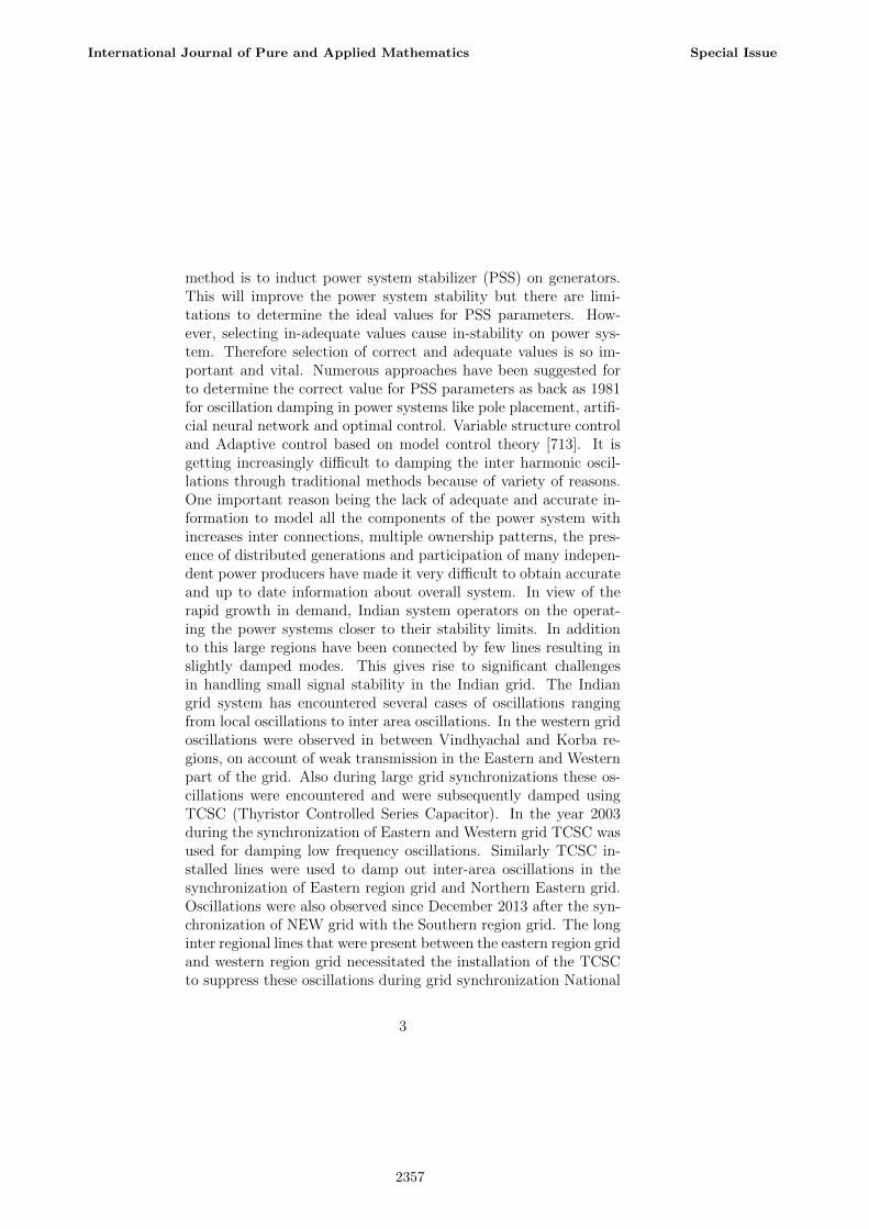
A three arm IGBT bridge is formed with an IGBT with backto back diode. The top three IGBTs are referred to us the positivegroups, while the bottom three IGBTs are referred to as negativegroup. When these IGBTs conduct an inverter operation takesplace while the diodes conduct a converter operation takes place.The concept of STATCOM power exchange is illustrated using thefigure 2. STATCOM can be considered to the an adjustable voltagesource behind a reactance in view of this there is no need to havecapacitor banks and shunt reactors to have reactive power genera-tion or absorption this factor accounts for the compact design of aSTATCOM.
Figure 2: Power exchange while using a STATCOM
The STATCOM equivalent circuit as shown in the figure 3.From the equivalent circuit it is observed that by changing theamplitudes of the 3Φ output voltage of the convertor, the exchangeof reactive power is controlled between the AC system and the con-vertor.
Figure 3: Equivalent circuit of STATCOM
6
International Journal of Pure and Applied Mathematics Special Issue
2360
In case the amplitude of Vout is higher than the amplitudeof the bus voltage Vac then there is flow of current through thereactance from the convertor to the AC system. In this case theconvertor generates capacitive reactive power for the AC system.The other case if the amplitude Vac is less than Vout there is acurrent flow from the Ac system into the convertor. In this casethe convertor absorbs inductive reactive power from the AC system.If the voltages are equal then the STATCOM is at floating state andreactive power exchange becomes zero. A small DC capacitor at DCside Vsc reactively limits the ability of STATCOM reactive powerexchange with in a transmission system. The coupling transformerhas two volts in its first role it connects the convertor to the highvoltage power system and in its second role it prevents the shortcircuit in DC capacitor and rapid discharge this is brought aboutthrough the transformers inductance.b. Modelling of UPFC
The unified power flow controllers are in a position to offerconcurrent control of multiple power system parameters,includingtransmission phase angleandvoltage impedance. This controlleris capable of providing reactive shunt make up phase fitting se-ries compensation and is also capable to multiple control objectivemaintenance. The UPFC can be formed by appliances such as ashunt connected transformer and a voltage source converter in aparallel branch along with the dc capacitor. The UPFC furtherincorporates a series injected transformer and voltage source con-verter. The common dc link capacitor is usually used to operatethe two voltage source converters which are connected to as backto back, AC to DC voltage source converters.
Mainly the shunt converter is used to give demand of activepower of series converter with common dc link. This converter-1 is also capable to delivers or absorbs the reactive power. Thiscan be achieved on demand and hence it gives independent shuntreactive compensation for the line. The converter-2 performs themain working of UPFC by injecting controlled voltage phase angleand magnitude with the line in series. The back to back convertersalong with the transformers are depicted using the figure 4.
The figure 5 shows the equivalent UPFC circuit. The series con-verter can replace with controllable voltage source Vse and shuntconverter to be replaced by a controllable current source, in the
7
International Journal of Pure and Applied Mathematics Special Issue
2361
Figure 4: Structure of UPFC as connected in the network
Figure 5: Equivalent circuit of UPFC
equivalent circuit. While the magnitude of the output voltage reg-ulates the voltage, its angle Φs is used for phase regulation. UPFCcontrollable parameters include: magnitude of the voltage injectedin the series with the transmission line, Vse with the ranges [0, Vse
max], phase angle of the same voltage injected, Φs that is withinthe range [1, 2π] and the shunt reactive current Ish, with the ranges[Ishmin, Ishmax]. [15].
3 THE PROPOSED ST CONTROLLER
The algorithm assumes the process to be described by a discreteARMA model of the form
(1)
8
International Journal of Pure and Applied Mathematics Special Issue
2362
Figure 6: Proposed configuration to damp oscillations
Where polynomials A(z−1) and B(z−1) in backward shift oper-ator z1 are defined as
Wherenb= order of the polynomial A(z−1)na= order of the polynomial B(z−1)and variables e(t) ,y(t) and u(t) are white noise, the system out-
put and system input respectively. Equation (1) can be rewrittenfor suitable identification as
(2)
(3)
9
International Journal of Pure and Applied Mathematics Special Issue
2363
(4)
(5)
WhereϕT (t) = Stored data vector of system output of last na samples
and system input of the last nb samples.The prediction error, ε(t) is given by
(6)
The RLS criterion finds the most likelihood value of θ̂(t) whichminimizes prediction error estimation.
(7)
The system parameter vector θ̂(t) can be calculated by belowrecursive equations
(8)
(a)where the weighing factor for the last identified parameters is
equal to one and that for the prediction error is given by the mod-ification coefficients (or gain matrix)k(t)
10
International Journal of Pure and Applied Mathematics Special Issue
2364
where ρ(t) is the time varying forgetting factor, is the covariance(of error in estimate) matrix, and k(t) is the gain vector. Theforgetting factor ρ(t) is calculated as
The RLS algorithm in every iteration uses a set of previous andpresent system measurements to find the system output (t) andalso calculates the prediction error ε(t). By using and the storedmeasured values in error covariance matrix P(t-1), then estimates aset of modification coefficients k(t). With k(t) a new set of identifiedsystem parameters θ̂(t) is measured as in (8a).
Eq.(8a) is modified by a constrained-RLS identification tech-nique with the inclusion as constraint term.
(9)
Where β(t) is calculated at each sampling instant as follows:
denotes the corresponding vector normalization and positiveconstant β0 which determines the parameter update rate. At faultinception (and after short duration) of power system, the N2/N1
11
International Journal of Pure and Applied Mathematics Special Issue
2365
ratio enhances faster as greater than β0. At time period β(t) usesthe value β0/N2 lesser the estimation rate and there by contribut-ing to smoother action of controller. After removal of fault whenthe power system reaching to a stable operating point, the ratioN2/N1 gradually enhances to less than β0 to get β(t)=1. For iden-tification process both ST controller and third-order ARMA systemmodel is used in proposed model. Inter-area mode of oscillationsat the range of 0.1 to 0.8 Hz exhibits by two-area system is subjectto a disturbance and to reduce this disturbance of oscillations athird-order model has been found in local mode as discussed in theintroduction. Complex conjugate poles (oscillatory) and real poles(Non- oscillatory) instability of system so second order and fourthorder models are not useful. Complex poles (two pairs) can onlyrepresent the oscillatory response, two or four real poles generallyare not needed to show the non-oscillatory part of a single modeinter-area oscillation. 5th, 7th, 9th or higher odd numbered modelscould be used.
4 RESULTS AND DISCUSSION
Two area systems [16] are benchmark systems for study of inter-areaoscillations , on each area it consists of two generators , connectedthrough a 220 km tie line. Generally all generators are connectedwith DC exciter models and transient models. Figure.7 shows Thetest system on-line diagram. Because the FACTS devices are origi-nated in transmission systems, local input signals like bus voltagesor bus currents, power deviation δP are preferable always. In thispaper, feedback signal is represented by δP. The important casechoosing the feedback signal is done by the optimal sitting of theFACTS device.
The results of the system without controller, with PI controllerand with self tuning controller of STATCOM and UPFC are shownusing Table 2.0 and Table 3.0. From the tables it can be observedthat there is significant reduction in settling time for both UPFCand STATCOM based controllers. The performance is better com-pared to a standalone PI controller as well. In all cases of analyze,the self-tuning controller is capable to reduce the power oscillationswithin few seconds from its activation and the damping ratio values
12
International Journal of Pure and Applied Mathematics Special Issue
2366
Figure 7: Line diagram of two area system
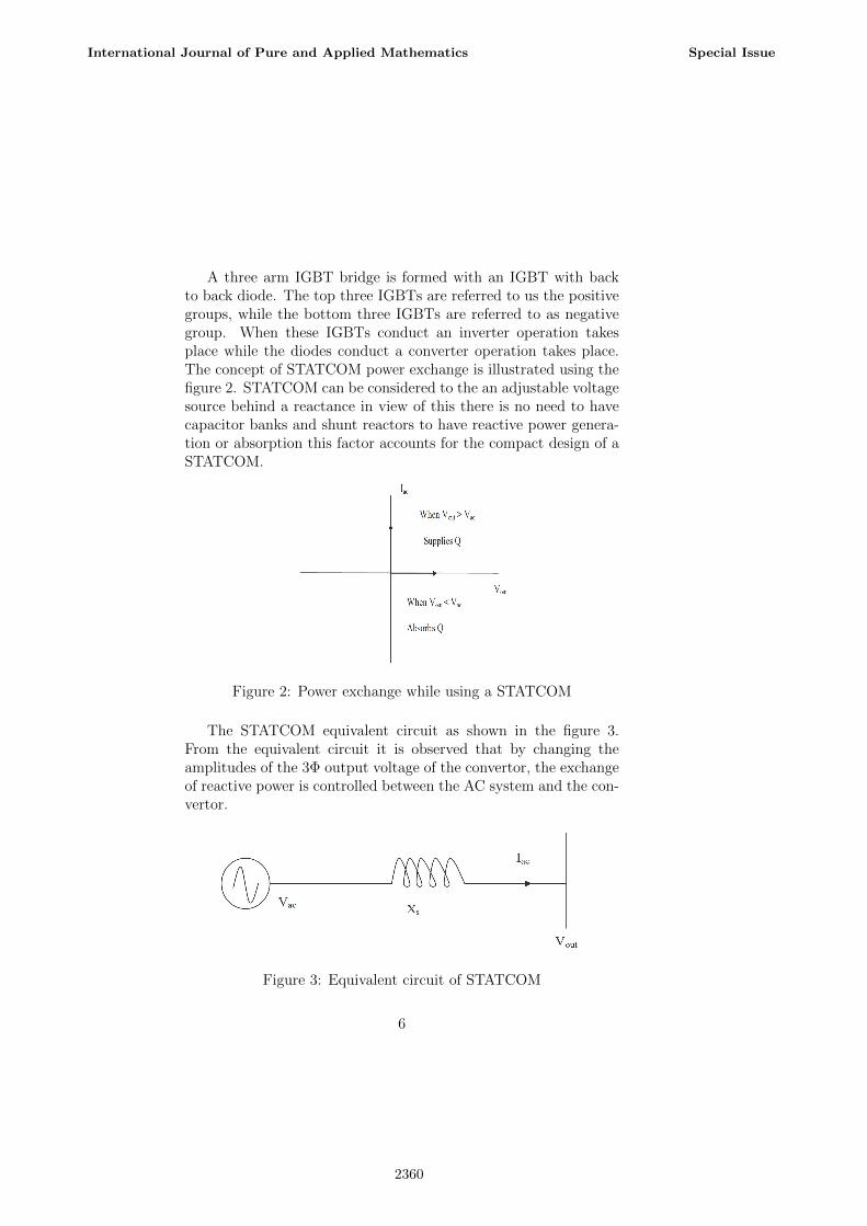
are acceptable instead of delay time resulting the signal condition-ing at the first oscillation cycle. It can be seen that the dampingtimes have improved from as given in Table 2.0 and Table 3.0 Inorder to further check controller ability to stabilize the system inthe presence of a Single Phase fault a fault is applied at bus 8 in thesystem. It is observed that when the ST controller is operating thedamping of the oscillation has been significantly improved. It canbe inferred from the tables that the performance of the proposedcontroller is clearly visible for all three types of faults induced at todifferent buses namely bus 7 and bus 8. The average reduction insettling time for the STATCOM based controller is 16.34 % whencompared to the scenario in which no damping controller is present.
13
International Journal of Pure and Applied Mathematics Special Issue
2367
On the other hand when the comparison is made in regard to PIcontroller the average reduction for all the fault cases is 2.81%
When the comparison is made between STATCOM and UPFC,the UPFC based controller delivers a better performance acrossall the fault scenarios. The average reduction in settling time forthe STATCOM based controller is 22.80 % when compared to thescenario in which no damping controller is present. On the otherhand when the comparison is made in regard to PI controller theaverage reduction for all the fault cases is 11.76. It can be inferredfrom the results that the reduction achieved by UPFC is enhancedin comparison to STATCOM and PI. There is significant reductionof 11.76 % for UPFC when compared to a PI based compensator,this is close to 8% enhancement when compared with reductionpercentage of STATCOM over PI.
In order to validate the performance of the proposed controllerin terms of enhancement of damping ratio a 4 cycle single phasefault and a 4 Cycle three phase fault is applied between bus 8and the ground. The results for this scenario are depicted usingTable 3.0 and Table 4.0. The enhancement of damping ratio iscompared in the absence of a controller and also in the presence ofa conventional PI damping controller.
Figure (8) and Figure (9) clearly demonstrates the enhanceddamping performance delivered by the proposed ST controllers.
14
International Journal of Pure and Applied Mathematics Special Issue
2368
Here also both the FACTS based controllers outperform PI baseddamping control in delivering an enhanced damping ratio.
The UPFC based damping controller delivers an enhanced per-formance when compared to the STATCOM based controller. Itcan be inferred from table 6.0 that the enhancement of dampingratio for a UPFC base controller is 22.2% when compared to a nocontroller configuration in the case of a 4 Cycle 3 Phase to faultbetween bus 8 and ground. For the same scenario the damping
15
International Journal of Pure and Applied Mathematics Special Issue
2369
Figure 8: Damping performance measured in terms of dampingratio of the proposed approach using STATCOM for damping interarea oscillations
ratio provided by the STATCOM based controller is 15.9 % whichis around 6 % lesser than the damping ratio provided UPFC basedcontroller. The performance is visible for 4 Cycle 1 Phase faultbetween bus 8 and ground. The improvement is damping ratio is10.2 for UPFC based control while the improvement is 6.06 % fora STATCOM based controller. This translates to 4 % improvedenhancement for UPFC over STATCOM based damping controller.
16
International Journal of Pure and Applied Mathematics Special Issue
2370
Figure 9: Damping performance measured in terms of dampingratio of the proposed approach using UPFC for damping inter areaoscillations
5 CONCLUSION
Self tuning controller has applied to UPFC and STATCOM is pre-sented in this paper. Simulation results shows that proposed method
17
International Journal of Pure and Applied Mathematics Special Issue
2371
automatically improves the damping characteristic in different modeof operating conditions. For avoiding interactions among the con-trollers the tuning is done in a coordinated way. Self-Tuning Regu-lator is a investigated controller and the system model parametersestimated by Recursive Least-Squares method. For transient sta-bility improvement an open-loop controller is used and also powerflow control by closed-loop PI-controller is presented. Different op-erating conditions of the four-machine system have been used tovalidate the proposed self-tuned controller. The obtained resultsproved that the proposed controller has successfully provided thegood damping for inter harmonic oscillations for the multi machinepower system.
References
[1] ”Proposed terms and definitions for flexible AC transmissionsystem (FACTS),” in IEEE Transactions on Power Delivery,vol. 12, no. 4, pp. 1848-1853, Oct 1997.
[2] F.P.deMello, C.Concordia, ”Concepts ofsynchronous machinestability as affected by excitationcontrol”, IEEE Trans. PAS,vo1.88, pp.316-329, 1969
[3] E.V.Larsen, D.A.Swann, ”Applying power systems stabiliz-ers”, Pts. I,II,III, IEEE Trans. PAS, vo1.100, pp.3017-3046,198 1.
[4] N.G.Hingorani, ”Flexible AC Transmission”, IEEESpectrum,vo1.30, pp.40-45, April 1993.
[10] Q.Lu, Y.Z.Sun, G.K.F.Lee, ”Nonlinear optimalexcitation con-trol for multimachine systems”, IFACPower Systems Mod-elling and Control Applications.Brussels, Belgium, 1988,pp.27-32.
[11] J.W.Chapman, M.D.Ilic, C.A.King,”Stabilizing amultima-chine power system via decentralized feedback linearizing exci-tation control”, Pre-print, IEEE PESSummer Meeting, 1992,SM 540-5 PWRS
[12] Y.Wang, L.Xie, DJ.Hill, R.H.Middleton,”Robustnonlinearcontroller design for transient stability enhancement of powersystems”, Proc. IEEE Conf.Decision and Cont., Tucson, 1992,pp.1149-1153
[13] Y .Wang, R.R.Mohler, R.Spee, W.Mittelstadt,”Variable struc-ture FACTS controllers for power systemtransient stability”,IEEE Trans. PS, vo1.7, pp.307-313,1992
[14] Report on Low Frequency Oscillation in Indian Power SystemMarch 2016,
[15] B. Minooie and M. Sedighizadeh, Technical Journal of Engi-neering and Applied Sciences , 1062 (2013)
[16] P. Kundur, Power System Stability and control, McGraw Hill,New York,1994.
19
International Journal of Pure and Applied Mathematics Special Issue