81 M.R. Talaghat et al. / Journal of Chemical and Petroleum Engineering, 51 (2), December 2017 / 81-94 A Novel Study of Upgrading Catalytic Reforming Unit by Improving Catalyst Regeneration Process to Enhance Aromatic Compounds, Hydrogen Production, and Hydrogen Purity Mohammad Reza Talaghat*, Aliakbar Roosta and Iman Khosrozadeh Department of Chemical Engineering, Shiraz University of Technology, Shiraz, Iran. (Received 2016.07.10, Accepted 2017.07.18) Abstract Catalytic reforming is a chemical process utilized in petroleum refiner- ies to convert naphtha, typically having low octane ratings, into high octane liquid products, called reformates, which are components of high octane gasoline. In this study, a mathematical model was developed for simulation of semi-regenerative catalytic reforming unit and the result of the pro- posed model was compared with the plant data to verify accuracy of the model. Then, an extra fixed bed reactor was added for upgrading the semi-regenerative process to cyclic process. The optimal condition of the cyclic process was calculated mathematically. The results show that the proposed configuration is capable to enhance the octane num- ber, yield of product, hydrogen production rate, and hydrogen purity by 1.5%, 7.14%, 8.1%, and 13.2%, respectively. The modifications im- prove the performance in comparison with the current facilities. The results indicate that aromatic and hydrogen production and hydrogen purity improve in comparison with the semi-regenerative reformat- ting process. Due to the additional swing reactor, which is a spare one, each of the reactors must be removed for regeneration process and, then, be replaced with a rebuilt one. Keywords Catalytic naphtha reform- ing; Modeling; Octane number enhance- ment; Hydrogen production; Upgrade of semi-regenera- tive reformer. Introduction 1 * Corresponding Author. Tel.: +98 9173170434 / Fax: +98 711 7354520 Email: [email protected] (M.R. Talaghat) 1. Introduction atalytic reforming is a chemical process utilized in petroleum refineries to convert naphtha, typically having low octane rat- ings, into high octane liquid products, called refor- mates, which are components of high octane gas- oline. A reformat is an excellent gasoline blend stock, which has a high content of benzene, tolu- ene, xylene (BTX) [1-3]. In addition, hydrogen as a desirable by-product is produced in this process [1-3]. Hydrogen will be a requisite energy source in the upcoming future. In the refineries, hydro- gen is used for processing of crude oil into refined fuels, such as gasoline and diesel. According to the environmental protection law, sulfur and ni- C
Transcript
81M.R. Talaghat et al. / Journal of Chemical and Petroleum Engineering, 51 (2), December 2017 / 81-94
A Novel Study of Upgrading Catalytic Reforming Unit by Improving Catalyst Regeneration Process
to Enhance Aromatic Compounds, HydrogenProduction, and Hydrogen Purity
Mohammad Reza Talaghat*, Aliakbar Roostaand Iman Khosrozadeh
Department of Chemical Engineering, Shiraz University of Technology, Shiraz, Iran.
(Received 2016.07.10, Accepted 2017.07.18)
Abstract
Catalytic reforming is a chemical process utilized in petroleum refiner-ies to convert naphtha, typically having low octane ratings, into high octane liquid products, called reformates, which are components of high octane gasoline.In this study, a mathematical model was developed for simulation of semi-regenerative catalytic reforming unit and the result of the pro-posed model was compared with the plant data to verify accuracy of the model. Then, an extra fixed bed reactor was added for upgrading the semi-regenerative process to cyclic process. The optimal condition of the cyclic process was calculated mathematically. The results show that the proposed configuration is capable to enhance the octane num-ber, yield of product, hydrogen production rate, and hydrogen purity by 1.5%, 7.14%, 8.1%, and 13.2%, respectively. The modifications im-prove the performance in comparison with the current facilities. The results indicate that aromatic and hydrogen production and hydrogen purity improve in comparison with the semi-regenerative reformat-ting process. Due to the additional swing reactor, which is a spare one, each of the reactors must be removed for regeneration process and, then, be replaced with a rebuilt one.
Keywords
Catalytic naphtha reform-ing;Modeling;Octane number enhance-ment;Hydrogen production;Upgrade of semi-regenera-tive reformer.
1. Introduction atalytic reforming is a chemical process utilized in petroleum refineries to convert naphtha, typically having low octane rat-
ings, into high octane liquid products, called refor-
mates, which are components of high octane gas-oline. A reformat is an excellent gasoline blend stock, which has a high content of benzene, tolu-ene, xylene (BTX) [1-3]. In addition, hydrogen as a desirable by-product is produced in this process [1-3]. Hydrogen will be a requisite energy source in the upcoming future. In the refineries, hydro-gen is used for processing of crude oil into refined fuels, such as gasoline and diesel. According to the environmental protection law, sulfur and ni-
C
82 M.R. Talaghat et al. / Journal of Chemical and Petroleum Engineering, 51 (2), December 2017 / 81-94
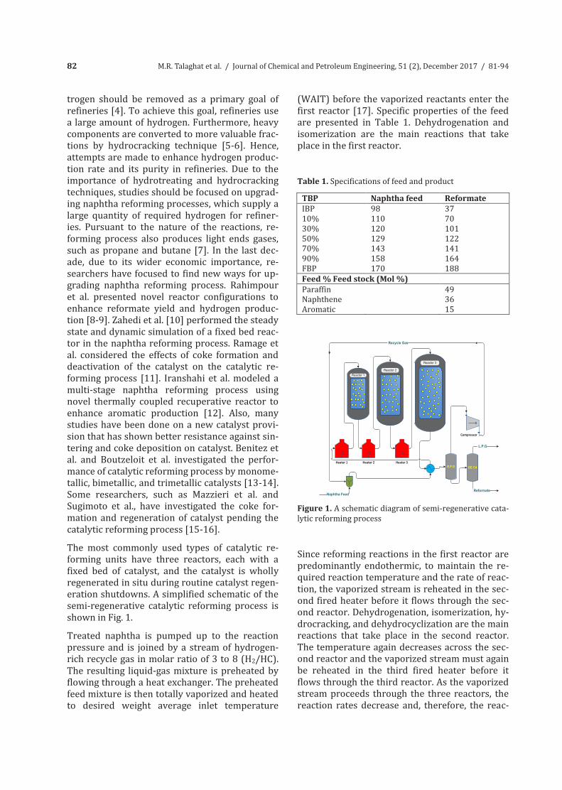
trogen should be removed as a primary goal of refineries [4]. To achieve this goal, refineries use a large amount of hydrogen. Furthermore, heavy components are converted to more valuable frac-tions by hydrocracking technique [5-6]. Hence, attempts are made to enhance hydrogen produc-tion rate and its purity in refineries. Due to the importance of hydrotreating and hydrocracking techniques, studies should be focused on upgrad-ing naphtha reforming processes, which supply a large quantity of required hydrogen for refiner-ies. Pursuant to the nature of the reactions, re-forming process also produces light ends gases, such as propane and butane [7]. In the last dec-ade, due to its wider economic importance, re-searchers have focused to find new ways for up-grading naphtha reforming process. Rahimpour et al. presented novel reactor configurations to enhance reformate yield and hydrogen produc-tion [8-9]. Zahedi et al. [10] performed the steady state and dynamic simulation of a fixed bed reac-tor in the naphtha reforming process. Ramage et al. considered the effects of coke formation and deactivation of the catalyst on the catalytic re-forming process [11]. Iranshahi et al. modeled a multi-stage naphtha reforming process using novel thermally coupled recuperative reactor to enhance aromatic production [12]. Also, many studies have been done on a new catalyst provi-sion that has shown better resistance against sin-tering and coke deposition on catalyst. Benitez et al. and Boutzeloit et al. investigated the perfor-mance of catalytic reforming process by monome-tallic, bimetallic, and trimetallic catalysts [13-14]. Some researchers, such as Mazzieri et al. and Sugimoto et al., have investigated the coke for-mation and regeneration of catalyst pending the catalytic reforming process [15-16]. The most commonly used types of catalytic re-forming units have three reactors, each with a fixed bed of catalyst, and the catalyst is wholly regenerated in situ during routine catalyst regen-eration shutdowns. A simplified schematic of the semi-regenerative catalytic reforming process is shown in Fig. 1. Treated naphtha is pumped up to the reaction pressure and is joined by a stream of hydrogen-rich recycle gas in molar ratio of 3 to 8 (H2/HC). The resulting liquid-gas mixture is preheated by flowing through a heat exchanger. The preheated feed mixture is then totally vaporized and heated to desired weight average inlet temperature
(WAIT) before the vaporized reactants enter the first reactor [17]. Specific properties of the feed are presented in Table 1. Dehydrogenation and isomerization are the main reactions that take place in the first reactor. Table 1. Specifications of feed and product
Figure 1. A schematic diagram of semi-regenerative cata-lytic reforming process
Since reforming reactions in the first reactor are predominantly endothermic, to maintain the re-quired reaction temperature and the rate of reac-tion, the vaporized stream is reheated in the sec-ond fired heater before it flows through the sec-ond reactor. Dehydrogenation, isomerization, hy-drocracking, and dehydrocyclization are the main reactions that take place in the second reactor. The temperature again decreases across the sec-ond reactor and the vaporized stream must again be reheated in the third fired heater before it flows through the third reactor. As the vaporized stream proceeds through the three reactors, the reaction rates decrease and, therefore, the reac-
83M.R. Talaghat et al. / Journal of Chemical and Petroleum Engineering, 51 (2), December 2017 / 81-94
trogen should be removed as a primary goal of refineries [4]. To achieve this goal, refineries use a large amount of hydrogen. Furthermore, heavy components are converted to more valuable frac-tions by hydrocracking technique [5-6]. Hence, attempts are made to enhance hydrogen produc-tion rate and its purity in refineries. Due to the importance of hydrotreating and hydrocracking techniques, studies should be focused on upgrad-ing naphtha reforming processes, which supply a large quantity of required hydrogen for refiner-ies. Pursuant to the nature of the reactions, re-forming process also produces light ends gases, such as propane and butane [7]. In the last dec-ade, due to its wider economic importance, re-searchers have focused to find new ways for up-grading naphtha reforming process. Rahimpour et al. presented novel reactor configurations to enhance reformate yield and hydrogen produc-tion [8-9]. Zahedi et al. [10] performed the steady state and dynamic simulation of a fixed bed reac-tor in the naphtha reforming process. Ramage et al. considered the effects of coke formation and deactivation of the catalyst on the catalytic re-forming process [11]. Iranshahi et al. modeled a multi-stage naphtha reforming process using novel thermally coupled recuperative reactor to enhance aromatic production [12]. Also, many studies have been done on a new catalyst provi-sion that has shown better resistance against sin-tering and coke deposition on catalyst. Benitez et al. and Boutzeloit et al. investigated the perfor-mance of catalytic reforming process by monome-tallic, bimetallic, and trimetallic catalysts [13-14]. Some researchers, such as Mazzieri et al. and Sugimoto et al., have investigated the coke for-mation and regeneration of catalyst pending the catalytic reforming process [15-16]. The most commonly used types of catalytic re-forming units have three reactors, each with a fixed bed of catalyst, and the catalyst is wholly regenerated in situ during routine catalyst regen-eration shutdowns. A simplified schematic of the semi-regenerative catalytic reforming process is shown in Fig. 1. Treated naphtha is pumped up to the reaction pressure and is joined by a stream of hydrogen-rich recycle gas in molar ratio of 3 to 8 (H2/HC). The resulting liquid-gas mixture is preheated by flowing through a heat exchanger. The preheated feed mixture is then totally vaporized and heated to desired weight average inlet temperature
(WAIT) before the vaporized reactants enter the first reactor [17]. Specific properties of the feed are presented in Table 1. Dehydrogenation and isomerization are the main reactions that take place in the first reactor. Table 1. Specifications of feed and product
Figure 1. A schematic diagram of semi-regenerative cata-lytic reforming process
Since reforming reactions in the first reactor are predominantly endothermic, to maintain the re-quired reaction temperature and the rate of reac-tion, the vaporized stream is reheated in the sec-ond fired heater before it flows through the sec-ond reactor. Dehydrogenation, isomerization, hy-drocracking, and dehydrocyclization are the main reactions that take place in the second reactor. The temperature again decreases across the sec-ond reactor and the vaporized stream must again be reheated in the third fired heater before it flows through the third reactor. As the vaporized stream proceeds through the three reactors, the reaction rates decrease and, therefore, the reac-
tors become larger. Hydrocracking and dehydro-cyclization are the main reactions that occur in this reactor. The product of the last reactor is separated into liquid and gas phases in reactor product separator (R.P.S). Table 2 shows the characterizations and operational conditions of naphtha reforming reactors. Catalytic reforming processes are commonly classified, according to the frequency and mode of catalyst regeneration, into (1) semi-regenerative, (2) cyclic, and (3) con-tinuous. Table 2. Reactors characterizations and conditions
Reactor Parameter 1st 2nd 3rd dis (wt %) d (m)
20.26 1.524
30 1.676
49.74 1.981
Parameter Numerical value Unit Naphtha feed H2/HC LHSV WHSV Mwave
56 4.8 1.92 2.04 108.47
m3/hr - hr-1
hr-1
kg/mol A semi-regenerative catalytic reforming process usually has 3 or 4 reactors in series with a fixed bed catalyst system and operates continuously (cycle length) from 6 months to one year. During this period, the activity of the catalyst diminishes due to coke deposition, provoking a decrease in aromatic yield and in hydrogen purity [18-19]. The cyclic regenerative reformer operates under more severe process conditions than the semi-regenerative process does. In this process, apart from the catalytic reforming reactors, the cyclic regeneration process has an additional swing re-actor, which is used when the fixed bed catalyst of any of the regular reactors needs regeneration. The reactor with the regenerated catalyst then becomes the spare reactor. By this, the reforming process maintains continuous operation. There-fore, the reforming operation can operate for a much longer period as a part of the catalyst is pe-riodically regenerated using a swing reactor [18-19]. The deficiencies in cyclic regeneration re-forming are solved by a low-pressure continuous regeneration process, which is characterized by high catalyst activity with reduced catalyst re-quirements, producing more uniform reformate of higher aromatic content and high hydrogen purity. Continuous regeneration typically consists of 3 to 4 radial flow reactors. This type of process uses moving bed reactor design, in which the re-
actors are stacked. The catalyst bed moves by gravity flow from top to bottom of the stacked reactors. The spent catalyst is withdrawn from the last reactor and sent to the top of the regen-erator to burn off the coke. The transport of cata-lyst between reactors and regenerator is done by the gas lift method. For more information, a con-ceptual design for a radial flow reactor in the cat-alytic reforming process is given in Fig. 2.
Figure 2. A conceptual design for radial flow reactor in catalytic reforming process
The semi-regenerative reforming process is de-scribed by operations at approximately low se-verity as restricted by certain operation condi-tions, naphtha quality, and catalyst management, which lengthen the cycle duration (cycle length) or, in other words, the time between catalyst re-generations. In the present study, the effects of temperature, pressure, space velocity, and hydro-gen to hydrocarbon ratio have been investigated to enhance the octane number and yield of the products. Also, the effect of each parameter to decrease coke deposition in the catalyst surface area in the semi-regenerative naphtha reforming process has been investigated. After that, it is proposed to add an extra fixed bed reactor to upgrade semi-regenerative process to cyclic process, and apply the best conditions to increase octane number, yield, and hydrogen production rate as well as it purity in this new configuration. In this work, the operating data of the Shiraz oil refinery were collected for two
84 M.R. Talaghat et al. / Journal of Chemical and Petroleum Engineering, 51 (2), December 2017 / 81-94
years. After simulation of naphtha reforming unit using the Smith model, the results of the model were used for sensitivity analysis of the catalytic reforming unit.
2. Reaction Characterization The commonly used catalytic reforming catalysts contain noble metals such as platinum and/or rhenium, which are very susceptible to poisoning by sulfur and nitrogen compounds. Specifications of conventional catalyst and catalyst bed are re-ported in Tables 3 and 4, respectively. Naphtha feedstock is always pre-processed in a desulfuri-zation unit, which removes both the sulfur and the nitrogen compounds. Depending upon the type or version of catalytic reforming used as well as the desired reaction severity, the reaction con-ditions range from temperatures of about 495 to 525°C and from gauge pressures of about 5 to 45 atmospheres. Desirable and undesirable reac-tions are two categories of reaction involved in the naphtha reforming process [18]. Desirable reactions lead to a higher octane number and may also produce hydrogen. Table 3. Typical properties of catalyst
Parameter Value Unit dp 1.2 mm Pt 0.3 wt % Re 0.4 wt % Sa 220 m2g-1 PV 0.6 cm3g-1 ρb 0.3 Kgl-1 ε 0.36 - Sld 0.58 Kg/L Dld 0.68 Kg/L
Table 4. Specifications of catalyst bed of reactors
Reactor Parameter 1st 2nd 3rd A (m2) 1.36 1.70 2.49 H (m) 4.35 5.11 5.87 V (m3) 5.9 8.69 14.63 W (kg) 4148 6142 10185 Ld (Kg/m3) 703 706.8 696.2 dcp (mm) 420 420 420 db (mm) 1380 1530 1830
Dehydrogenation, dehydrocyclization and isom-erization are desirable reactions. A principal de-
sirable reaction is dehydrogenation, because it produces aromatics that have high octane num-bers and produce hydrogen. Dehydrocyclization is probably the most difficult reaction to promote in the naphtha reforming process. It predomi-nantly takes place in the last reactor in the train. It involves dehydrogenation with a release of one mole of hydrogen, followed by a molecular rear-rangement to form a naphthene and by the sub-sequent dehydrogenation of naphthene. The isomerization reaction is one in which the hydro-carbon formula remains the same, but the shape of the hydrocarbon molecule changes. In fact, a rearrangement takes place in the structure. Undesirable reactions are the reactions that lead to decrease in octane number, yield, and hydro-gen purity. They are the reactions that must be avoided. The breaking of C-C bond in reforming operation is called hydrocracking. Hydrocracking reaction breaks a Paraffin molecule into two mol-ecules of lower molecular weight or opens the ring of a naphthene. The main effects of hy-drocracking are decrease in hydrogen production, yield, and hydrogen purity and increase in light ends. Due to decrease in paraffins in reformate, it leads to increase in the aromatic concentration or, in other words, octane number. Hydrogenoly-sis has some similarities with hydrocracking in cleavage of bonds. Due to this undesirable reac-tion, paraffin compound breaks and methane or ethane is produced, resulting in reduced yield. Hydrodealkylation is the breakage of the branched radical of an aromatic ring, which con-sumes hydrogen and produces methane. The main effect of Hydrodealkylation is decrease in hydrogen production and yield. Alkylation is the addition of an Olefin molecule to an aromatic ring that leads to heavier molecules, which may in-crease the end point of the product and high ten-dency to form coke. Specifications of desirable reactions as well as undesirable reactions are de-scribed in Tables 5 and 6, respectively. Deposited coke on the catalyst is a temporary poison, since its detrimental effect is reversible through regeneration. Due to coke formation, the active contact area of catalysts decreases and cat-alyst activity is reduced.
85M.R. Talaghat et al. / Journal of Chemical and Petroleum Engineering, 51 (2), December 2017 / 81-94
years. After simulation of naphtha reforming unit using the Smith model, the results of the model were used for sensitivity analysis of the catalytic reforming unit.
2. Reaction Characterization The commonly used catalytic reforming catalysts contain noble metals such as platinum and/or rhenium, which are very susceptible to poisoning by sulfur and nitrogen compounds. Specifications of conventional catalyst and catalyst bed are re-ported in Tables 3 and 4, respectively. Naphtha feedstock is always pre-processed in a desulfuri-zation unit, which removes both the sulfur and the nitrogen compounds. Depending upon the type or version of catalytic reforming used as well as the desired reaction severity, the reaction con-ditions range from temperatures of about 495 to 525°C and from gauge pressures of about 5 to 45 atmospheres. Desirable and undesirable reac-tions are two categories of reaction involved in the naphtha reforming process [18]. Desirable reactions lead to a higher octane number and may also produce hydrogen. Table 3. Typical properties of catalyst
Parameter Value Unit dp 1.2 mm Pt 0.3 wt % Re 0.4 wt % Sa 220 m2g-1 PV 0.6 cm3g-1 ρb 0.3 Kgl-1 ε 0.36 - Sld 0.58 Kg/L Dld 0.68 Kg/L
Table 4. Specifications of catalyst bed of reactors
Reactor Parameter 1st 2nd 3rd A (m2) 1.36 1.70 2.49 H (m) 4.35 5.11 5.87 V (m3) 5.9 8.69 14.63 W (kg) 4148 6142 10185 Ld (Kg/m3) 703 706.8 696.2 dcp (mm) 420 420 420 db (mm) 1380 1530 1830
Dehydrogenation, dehydrocyclization and isom-erization are desirable reactions. A principal de-
sirable reaction is dehydrogenation, because it produces aromatics that have high octane num-bers and produce hydrogen. Dehydrocyclization is probably the most difficult reaction to promote in the naphtha reforming process. It predomi-nantly takes place in the last reactor in the train. It involves dehydrogenation with a release of one mole of hydrogen, followed by a molecular rear-rangement to form a naphthene and by the sub-sequent dehydrogenation of naphthene. The isomerization reaction is one in which the hydro-carbon formula remains the same, but the shape of the hydrocarbon molecule changes. In fact, a rearrangement takes place in the structure. Undesirable reactions are the reactions that lead to decrease in octane number, yield, and hydro-gen purity. They are the reactions that must be avoided. The breaking of C-C bond in reforming operation is called hydrocracking. Hydrocracking reaction breaks a Paraffin molecule into two mol-ecules of lower molecular weight or opens the ring of a naphthene. The main effects of hy-drocracking are decrease in hydrogen production, yield, and hydrogen purity and increase in light ends. Due to decrease in paraffins in reformate, it leads to increase in the aromatic concentration or, in other words, octane number. Hydrogenoly-sis has some similarities with hydrocracking in cleavage of bonds. Due to this undesirable reac-tion, paraffin compound breaks and methane or ethane is produced, resulting in reduced yield. Hydrodealkylation is the breakage of the branched radical of an aromatic ring, which con-sumes hydrogen and produces methane. The main effect of Hydrodealkylation is decrease in hydrogen production and yield. Alkylation is the addition of an Olefin molecule to an aromatic ring that leads to heavier molecules, which may in-crease the end point of the product and high ten-dency to form coke. Specifications of desirable reactions as well as undesirable reactions are de-scribed in Tables 5 and 6, respectively. Deposited coke on the catalyst is a temporary poison, since its detrimental effect is reversible through regeneration. Due to coke formation, the active contact area of catalysts decreases and cat-alyst activity is reduced.
Table 5. Specifications of desirable reactions
Table 6. Specifications of undesirable reactions
Coke formation is due to heavy unsaturated productions, such as polycyclic, which can be dehydrogenated. Since coke formation is inher-ently associated with the reforming reaction, there is no real way to avoid it. Coke will be re-duced by a decrease in reactor temperature and an increase in hydrogen circulation. At low pressure, coking will increase. In 1959, Smith proposed the first successful kinetic model for naphtha reforming process [20]. In this model, naphtha feed involved naph-thenic, paraffinic, and aromatic compounds. Al-so, he introduced hydrogen and light ends in addition to his model. The reactions are as fol-lows: Dehydrogenation of naphthenes to aromatic
1
12
2 2 6
3
( ) ( )
f
e
kK
n n n n
Naphthenes Aromatics H
C H C H
(1)
Dehydrocyclization of paraffins to naphthenes 2
22
2 2 6( ) ( )
f
e
kK
n n n n
Naphthenes H Paraffins
C H C H
(2)
Hydrocracking of naphthenes to lower hydro-carbons
32
2 1 5
32
( ) ( )
fk
n n
Naphthenes H Lighter ends
C H C C
(3)
Hydrocracking of paraffins to lower hydrocar-bons
42
2 2 1 5
( 3)3
( ) ( )
fk
n n
nParaffins H Lighter ends
C H C C
(4)
1
1
1
31 ( )( )f
e n a he
kr k p p p
K
(5)
2
2
2
2 ( )( )fe n h p
e
kr k p p p
K
(6)
33 ( )f
nt
kr p
p
(7)
43 ( )f
pt
kr p
p
(8)
The rate constants and heat of reactions are listed in Table 7.
Table 7. Rate constants and heat of reactions for naphtha reforming
Desirable reactions Reaction type Catalyst promoted
function Pressure condi-tion to promote Reaction rate
Naphthenes dehydrogenation Highly endother-mic Metallic part Low Very fast
Paraffins isomerization
Slightly endo-thermic Acidic part No effect Fast
Naphthenes isomerization Slightly endo-thermic Acidic part No effect Low
Dehydrocyclization Endothermic Both parts Low Very low Dehydroisomerization Endothermic Both parts Low Low
Undesirable reactions Reaction Type Catalyst Promoted Function
Pressure Condition to Promote Reaction Rate
Hydrocracking Exothermic Both Parts High Low Hydrogenolysis Exothermic Metallic High Low Hydrodealkylation Exothermic Metallic High Low Alkylation Exothermic Both Parts High Very low
86 M.R. Talaghat et al. / Journal of Chemical and Petroleum Engineering, 51 (2), December 2017 / 81-94
3. Mathematical Modeling A heterogeneous mathematical model is devel-oped by assembling the mass and energy bal-ance on the naphtha reforming system. The mass balance provides a variety of the concen-trations and the energy balance provides the variation of temperature along the reactors. Also, one of the main functions in naphtha re-forming is to consider the pressure drop through the catalyst bed. The Sabri Ergun pres-sure drop equation considered viscous changes as well as kinetic energy changes for a wide range of flow rates to account for the pressure drop through the reforming reactors [21-22]. In order to develop the mass and energy balance, the following assumptions are considered dur-ing the modeling step: 1) Axial dispersion of heat is neglected. 2) All the reactors work under adiabatic condi-tion. 3) Ideal gas behavior is applicable. 4) Plug flow pattern is considered. By considering component material balances as well as energy balance for a differential element ‘dw’ of the catalyst bed, the mass and energy balances are obtained as follows [24]: Mass balance:
,1
( ).n
i ii j j
j b
dF d crdw dt
(9)
Energy balance:
,1 1 1
1
( )c c c
i
c
cat i
n n n
i p j i i ji j i
n
p i pib
dTFC r HdwdT
dt C c C
(10)
Ergun equation:
3
150(1 ) 1( 1.75)p p c c
dP Gdw d d A
(11)
4. Results and Discussion 4.1. Model validation
The operating data of the Shiraz oil refinery were collected for two years. After simulation of naphtha reforming unit, the predicted results from the simulation were compared with plant
data and the ability of the model to predict the desired outputs was confirmed (Figs. 3 and 4).
Figure 3. Temperature profile along the reactors; a comparison between Smith model and plant data for semi-regenerative reforming at 3000kPa
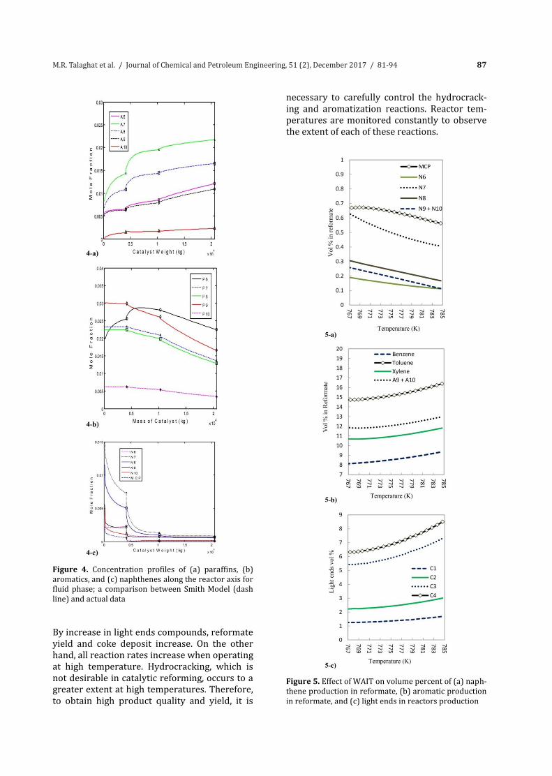
4.2. Effect of temperature on semi-regenerative process Catalyst activity is directly proportional to the temperature of the reactor. The reaction tem-perature is the most important variable in cata-lytic reforming, since the product quality and yield are highly dependent on it. Since reform-ers are designed with 3 or more reactors in se-ries and each reactor may contain a different quantity of catalyst, it is commonly accepted to consider the weighted average inlet tempera-ture (WAIT) [25-27]. In a conventional semi-regenerative unit, the loss of activity of catalyst results in decrease in product octane number as well as reformate yield and recycle gas purity. The effect of WAIT on volume percent of naph-thene, aromatic, and light ends production in reformate in reactors production is given in Fig. 5. In Fig. 5, the curves indicate that increasing the WAIT of the reactor leads to increase in conversion of the non-aromatic compounds in the feed to aromatic, although the hydrocrack-ing reaction is more favored than the cyclization of paraffins.
87M.R. Talaghat et al. / Journal of Chemical and Petroleum Engineering, 51 (2), December 2017 / 81-94
3. Mathematical Modeling A heterogeneous mathematical model is devel-oped by assembling the mass and energy bal-ance on the naphtha reforming system. The mass balance provides a variety of the concen-trations and the energy balance provides the variation of temperature along the reactors. Also, one of the main functions in naphtha re-forming is to consider the pressure drop through the catalyst bed. The Sabri Ergun pres-sure drop equation considered viscous changes as well as kinetic energy changes for a wide range of flow rates to account for the pressure drop through the reforming reactors [21-22]. In order to develop the mass and energy balance, the following assumptions are considered dur-ing the modeling step: 1) Axial dispersion of heat is neglected. 2) All the reactors work under adiabatic condi-tion. 3) Ideal gas behavior is applicable. 4) Plug flow pattern is considered. By considering component material balances as well as energy balance for a differential element ‘dw’ of the catalyst bed, the mass and energy balances are obtained as follows [24]: Mass balance:
,1
( ).n
i ii j j
j b
dF d crdw dt
(9)
Energy balance:
,1 1 1
1
( )c c c
i
c
cat i
n n n
i p j i i ji j i
n
p i pib
dTFC r HdwdT
dt C c C
(10)
Ergun equation:
3
150(1 ) 1( 1.75)p p c c
dP Gdw d d A
(11)
4. Results and Discussion 4.1. Model validation
The operating data of the Shiraz oil refinery were collected for two years. After simulation of naphtha reforming unit, the predicted results from the simulation were compared with plant
data and the ability of the model to predict the desired outputs was confirmed (Figs. 3 and 4).
Figure 3. Temperature profile along the reactors; a comparison between Smith model and plant data for semi-regenerative reforming at 3000kPa
4.2. Effect of temperature on semi-regenerative process Catalyst activity is directly proportional to the temperature of the reactor. The reaction tem-perature is the most important variable in cata-lytic reforming, since the product quality and yield are highly dependent on it. Since reform-ers are designed with 3 or more reactors in se-ries and each reactor may contain a different quantity of catalyst, it is commonly accepted to consider the weighted average inlet tempera-ture (WAIT) [25-27]. In a conventional semi-regenerative unit, the loss of activity of catalyst results in decrease in product octane number as well as reformate yield and recycle gas purity. The effect of WAIT on volume percent of naph-thene, aromatic, and light ends production in reformate in reactors production is given in Fig. 5. In Fig. 5, the curves indicate that increasing the WAIT of the reactor leads to increase in conversion of the non-aromatic compounds in the feed to aromatic, although the hydrocrack-ing reaction is more favored than the cyclization of paraffins.
Figure 4. Concentration profiles of (a) paraffins, (b) aromatics, and (c) naphthenes along the reactor axis for fluid phase; a comparison between Smith Model (dash line) and actual data
By increase in light ends compounds, reformate yield and coke deposit increase. On the other hand, all reaction rates increase when operating at high temperature. Hydrocracking, which is not desirable in catalytic reforming, occurs to a greater extent at high temperatures. Therefore, to obtain high product quality and yield, it is
necessary to carefully control the hydrocrack-ing and aromatization reactions. Reactor tem-peratures are monitored constantly to observe the extent of each of these reactions.
Figure 5. Effect of WAIT on volume percent of (a) naph-thene production in reformate, (b) aromatic production in reformate, and (c) light ends in reactors production
88 M.R. Talaghat et al. / Journal of Chemical and Petroleum Engineering, 51 (2), December 2017 / 81-94
4.3. Effect of pressure on semi-regenerative process
A reduction in the reactor pressure increases the hydrogen and reformate yield, decreases the required reactor temperature to achieve a con-stant product quality, and shortens the catalyst cycle by increasing the catalyst coking rate. Higher pressures cause higher rates of hy-drocracking and more hydrocracking causes a loss of reformate yield for a given octane num-ber [24-26]. The real incentive for reducing pressure in reformer reactors is more refor-mate yield with the added benefit of increased hydrogen. Fig. 6 represents the effect of pres-sure on R.O.N and yield in the naphtha reform-ing process. Due to catalyst distribution in the reactors, it is usually close to the inlet pressure of the last reactor.
Figure 6. Profiles of (a) research octane number and (b) the yield of semi-regenerative reformer versus catalyst age in various pressures to investigate the effect of pressure in reforming process
Fig. 7 demonstrates the effect of pressure on coke deposition on catalyst for each reactor. By
these graphs, the amount of coke formation on catalyst at various pressures is illustrated. As it can be noticed, at lower pressures, coke deposi-tion increases. The results of Fig. 6 and Fig. 7 show that it is better to keep the catalytic re-forming unit at the lowest practical pressure if coke deposition on catalyst does not make any problem on reactor condition.
Figure 7. Profiles of coke deposit on the catalyst in (a) reactor 1, (b) reactor 2, and (c) reactor 3 versus catalyst age in various pressures to investigate the effect of pressure on coke formation on catalyst in reforming process
89M.R. Talaghat et al. / Journal of Chemical and Petroleum Engineering, 51 (2), December 2017 / 81-94
4.4. Effect of hydrogen to hydrocarbon ratio
The profile of coke deposit on the catalyst at each reactor in various H2/HC ratios is illustrat-ed in Fig. 8. Recycled hydrogen is necessary in the reformer operation for purposes of catalyst stability. The hydrogen reacts with coke precur-sors, removing them from the catalyst before they can form polycyclic aromatics, which ulti-mately deactivate the catalyst [27]. Increase in H2/HC ratio causes increase in the hydrogen partial pressure and removes coke precursors from the metal sites. The global effect of this is increased catalyst life. In other words, the rate of coke formation on the catalyst and, thus, cata-lyst stability and life are functions of the H2/HC ratio and hydrogen partial pressure present in the reactor system. The H2/HC ratio has little influence on product quality or yield. Hydrogen partial pressure is set by an economic balance between the consumed energy by heaters, recy-cle gas, and cycle duration. 4.5. Effect of space velocity
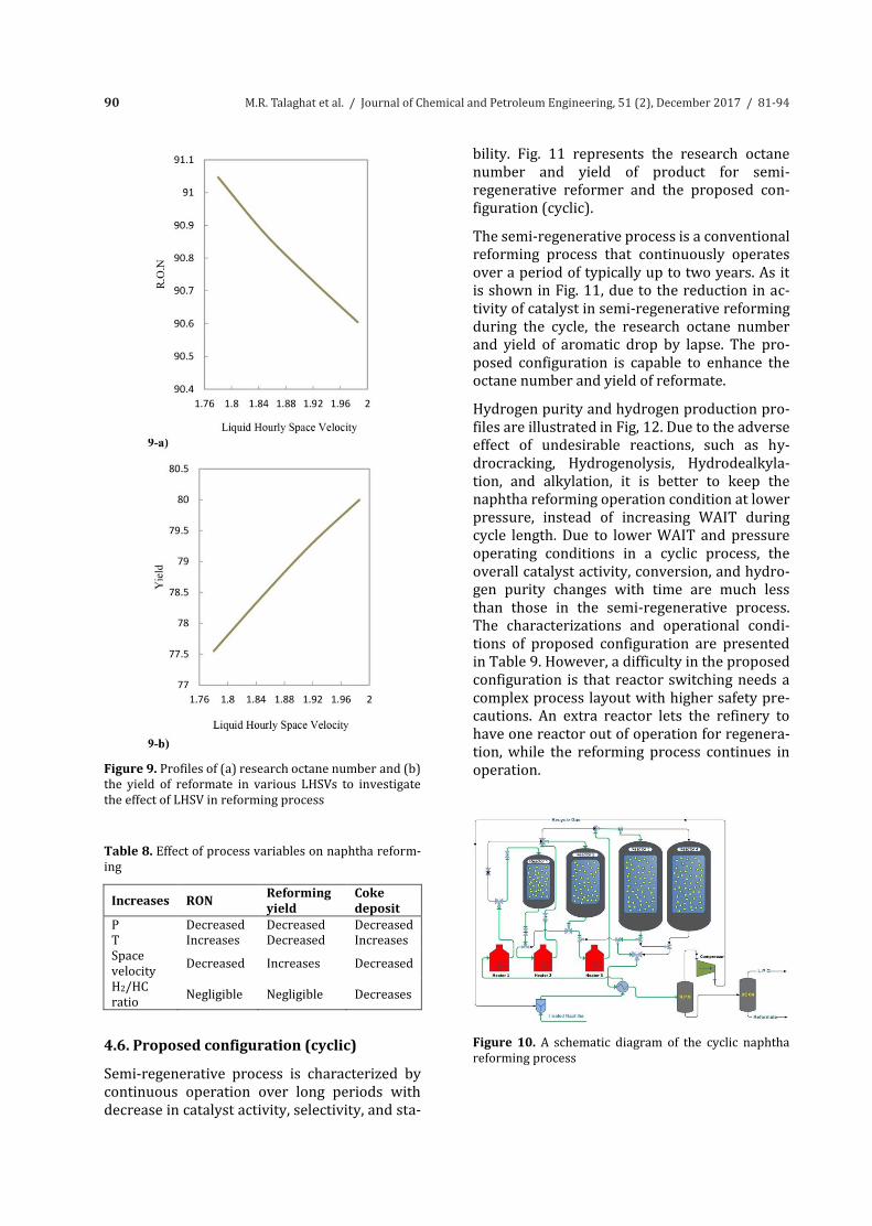
Space velocity is an important variable, because it is interchangeable with reaction temperature and it relates to the length of time of contact with the catalyst; thus, it affects the severity of reforming. The residence time of the feed in the reactor is the inverse of the liquid hourly space velocity (LHSV-1). The space velocity directly affects the kinetics of the reforming reactions. Decreasing the space velocity leads to increase in the residence time; hence, the higher the se-verity, which results in increase in octane num-ber, the lower the reformate yield and the high-er the coke deposit will be. The profiles of the research octane number and the yield profiles in various LHSVs to investigate the effect of LHSV in reforming process are given in Figs. 9(a) and 9(b), respectively. Also, the effect of process variables is gathered in Table 8. A schematic diagram of the cyclic naphtha re-forming process is illustrated in Fig. 10. In this configuration, for upgrading the semi-regenerative process, an extra fixed bed reactor is used with the same size as the third reactor. The flexibility of the proposed configuration allows refinery to operate at lower pressure and temperature, which results in gaining high-er yield, hydrogen production, and hydrogen purity.
Figure 8. Profiles of coke deposit on the catalyst in (a) reactor 1, (b) reactor 2, and (c) reactor 3 versus catalyst age in various H2/H.C rates to investigate the effect of H2/HC on coke formation on catalyst in reforming pro-cess
90 M.R. Talaghat et al. / Journal of Chemical and Petroleum Engineering, 51 (2), December 2017 / 81-94
Figure 9. Profiles of (a) research octane number and (b) the yield of reformate in various LHSVs to investigate the effect of LHSV in reforming process
Table 8. Effect of process variables on naphtha reform-ing
Increases RON Reforming yield
Coke deposit
P Decreased Decreased Decreased T Increases Decreased Increases Space velocity Decreased Increases Decreased H2/HC ratio Negligible Negligible Decreases
4.6. Proposed configuration (cyclic)
Semi-regenerative process is characterized by continuous operation over long periods with decrease in catalyst activity, selectivity, and sta-
bility. Fig. 11 represents the research octane number and yield of product for semi-regenerative reformer and the proposed con-figuration (cyclic). The semi-regenerative process is a conventional reforming process that continuously operates over a period of typically up to two years. As it is shown in Fig. 11, due to the reduction in ac-tivity of catalyst in semi-regenerative reforming during the cycle, the research octane number and yield of aromatic drop by lapse. The pro-posed configuration is capable to enhance the octane number and yield of reformate. Hydrogen purity and hydrogen production pro-files are illustrated in Fig, 12. Due to the adverse effect of undesirable reactions, such as hy-drocracking, Hydrogenolysis, Hydrodealkyla-tion, and alkylation, it is better to keep the naphtha reforming operation condition at lower pressure, instead of increasing WAIT during cycle length. Due to lower WAIT and pressure operating conditions in a cyclic process, the overall catalyst activity, conversion, and hydro-gen purity changes with time are much less than those in the semi-regenerative process. The characterizations and operational condi-tions of proposed configuration are presented in Table 9. However, a difficulty in the proposed configuration is that reactor switching needs a complex process layout with higher safety pre-cautions. An extra reactor lets the refinery to have one reactor out of operation for regenera-tion, while the reforming process continues in operation.
Figure 10. A schematic diagram of the cyclic naphtha reforming process
91M.R. Talaghat et al. / Journal of Chemical and Petroleum Engineering, 51 (2), December 2017 / 81-94
Figure 9. Profiles of (a) research octane number and (b) the yield of reformate in various LHSVs to investigate the effect of LHSV in reforming process
Table 8. Effect of process variables on naphtha reform-ing
Increases RON Reforming yield
Coke deposit
P Decreased Decreased Decreased T Increases Decreased Increases Space velocity Decreased Increases Decreased H2/HC ratio Negligible Negligible Decreases
4.6. Proposed configuration (cyclic)
Semi-regenerative process is characterized by continuous operation over long periods with decrease in catalyst activity, selectivity, and sta-
bility. Fig. 11 represents the research octane number and yield of product for semi-regenerative reformer and the proposed con-figuration (cyclic). The semi-regenerative process is a conventional reforming process that continuously operates over a period of typically up to two years. As it is shown in Fig. 11, due to the reduction in ac-tivity of catalyst in semi-regenerative reforming during the cycle, the research octane number and yield of aromatic drop by lapse. The pro-posed configuration is capable to enhance the octane number and yield of reformate. Hydrogen purity and hydrogen production pro-files are illustrated in Fig, 12. Due to the adverse effect of undesirable reactions, such as hy-drocracking, Hydrogenolysis, Hydrodealkyla-tion, and alkylation, it is better to keep the naphtha reforming operation condition at lower pressure, instead of increasing WAIT during cycle length. Due to lower WAIT and pressure operating conditions in a cyclic process, the overall catalyst activity, conversion, and hydro-gen purity changes with time are much less than those in the semi-regenerative process. The characterizations and operational condi-tions of proposed configuration are presented in Table 9. However, a difficulty in the proposed configuration is that reactor switching needs a complex process layout with higher safety pre-cautions. An extra reactor lets the refinery to have one reactor out of operation for regenera-tion, while the reforming process continues in operation.
Figure 10. A schematic diagram of the cyclic naphtha reforming process
Figure 11. Comparison of (a) the research octane num-ber and (b) the yield of reformate versus catalyst age for case (1) plant data for semi-regenerative reforming at 3000kPa, case (2) semi-regenerative reforming at 3000kPa, case (3) the proposed configuration at con-stant WAIT (768K) and 2000kPa, and case (4) the pro-posed configuration at constant WAIT (768K) and 2200kPa
Figure 12. Profiles of (a) hydrogen purity and (b) hy-drogen production versus cycle length. Comparison between case (1) semi-regenerative reforming at 3000kPa and case (2) the proposed configuration at constant WAIT (768K) and 2000kPa
92 M.R. Talaghat et al. / Journal of Chemical and Petroleum Engineering, 51 (2), December 2017 / 81-94
5. Conclusion In order to enhance octane number, yield, hydro-gen production, and hydrogen purity, a novel re-actor configuration has been proposed for an old semi-regenerative catalytic naphtha reforming process. Due to approximately low severity in semi-regenerative reforming, such as trend to-wards a lower octane number, yield, hydrogen production, and hydrogen purity by the lapse, and due to coke deposition on catalyst, the reforming operation may be shut down, which leads to a huge economic damage. To avoid these problems, the effects of temperature, pressure, space veloci-ty, and hydrogen to hydrocarbon ratios in semi-regenerative naphtha reforming process were investigated to assess each parameter in enhanc-ing the octane number and yield of the product. Also, the effect of each of these parameters on the reduction in coke deposition on the catalyst sur-face area was studied. Finally, for converting semi-regenerative process to cyclic process, a fixed bed reactor was added to the semi-regenerative reforming process to increase the octane number, and the rates of yield and purity of hydrogen production in this new configuration. 1.5%, 7.14%, 8.1%, and 13.2% improvements in the octane number, yield of reformate, hydrogen production rate, and hydrogen purity were ob-served, respectively. The results indicated that aromatic and hydrogen production and hydrogen purity improved in comparison with the semi-regenerative reformatting process. Due to the additional swing reactor (which is a spare reac-tor), each of the reactors must be removed for regeneration process to be replaced with a rebuilt reactor.
Nomenclature A Area, m2 dp Particle diameter, mm Sa Surface area, m2gr -1 H2 Hydrogen, kmol/h PV Total pore volume, cm3gr -1 kf1 Forward rate constant for reaction (5), kmol
h-1 kg cat-1 MPa-1 kf2 Forward rate constant for reaction (6), kmol
h-1 kg cat-1 MPa-1 kf3 Forward rate constant for reaction (7), kmol
h-1 kg cat-1 MPa-1 kf4 Forward rate constant for reaction (8), kmol
h-1 kg cat-1 MPa-1 ke1 Equilibrium constant for reaction (5), MPa3
ke2 Equilibrium constant for reaction (6), MPa3 Pi Partial pressure of the ith component, kPa P Total pressure, kPa T Temperature of gas phase, oK H Height, m V Volume, m3 W Weight, kg LD Loading density, kg/l dis Catalyst distribution, wt % db Bed diameter, mm d Reactor diameter, m
Greek Letters ε Void fraction of catalyst bed ρb Catalyst bulk density, kg m-3 ΔH Heat of reaction, kJ kmol-1 H2
Subscript a Aromatic, - h Hydrogen, - n Naphthene, - p Paraffin, -
Abbreviations
IBP Initial boiling point, oC FBP Final boiling point, oC RON Research octane number WAIT Weighted average inlet
Temperature, oC Pt Platinum Re Rhenium
References [1] Aitani, A.M. (2005). “Catalytic naphtha reform-ing.” Encyclopedia of Chemical Processing. S. Lee, ed., CRC Press, pp. 397–406. [2] Ancheyta-Juarez, J. and Villafuerte-Macias, E. (2000). “Kinetic modeling of naphtha catalytic reforming reactions.” Energy Fuels, Vol. 14 (5), pp. 1032-1037. [3] Speight, J.G. (2011). “The Refinery of the Fu-ture.” 1st Ed., William Andrew Publishing, Boston. [4] Pregger, T., Graf, D., Krewitt, W., Sattler, C. and Moller, S. (2009). “Prospects of solar thermal hy-drogen production processes.” Journal of Hydro-gen Energy, Vol. 34, pp. 4256- 4267. [5] Alves, J.J. and Towler, G.P. (2002). “Analysis of refinery hydrogen distribution systems.” Journal
93M.R. Talaghat et al. / Journal of Chemical and Petroleum Engineering, 51 (2), December 2017 / 81-94
5. Conclusion In order to enhance octane number, yield, hydro-gen production, and hydrogen purity, a novel re-actor configuration has been proposed for an old semi-regenerative catalytic naphtha reforming process. Due to approximately low severity in semi-regenerative reforming, such as trend to-wards a lower octane number, yield, hydrogen production, and hydrogen purity by the lapse, and due to coke deposition on catalyst, the reforming operation may be shut down, which leads to a huge economic damage. To avoid these problems, the effects of temperature, pressure, space veloci-ty, and hydrogen to hydrocarbon ratios in semi-regenerative naphtha reforming process were investigated to assess each parameter in enhanc-ing the octane number and yield of the product. Also, the effect of each of these parameters on the reduction in coke deposition on the catalyst sur-face area was studied. Finally, for converting semi-regenerative process to cyclic process, a fixed bed reactor was added to the semi-regenerative reforming process to increase the octane number, and the rates of yield and purity of hydrogen production in this new configuration. 1.5%, 7.14%, 8.1%, and 13.2% improvements in the octane number, yield of reformate, hydrogen production rate, and hydrogen purity were ob-served, respectively. The results indicated that aromatic and hydrogen production and hydrogen purity improved in comparison with the semi-regenerative reformatting process. Due to the additional swing reactor (which is a spare reac-tor), each of the reactors must be removed for regeneration process to be replaced with a rebuilt reactor.
Nomenclature A Area, m2 dp Particle diameter, mm Sa Surface area, m2gr -1 H2 Hydrogen, kmol/h PV Total pore volume, cm3gr -1 kf1 Forward rate constant for reaction (5), kmol
h-1 kg cat-1 MPa-1 kf2 Forward rate constant for reaction (6), kmol
h-1 kg cat-1 MPa-1 kf3 Forward rate constant for reaction (7), kmol
h-1 kg cat-1 MPa-1 kf4 Forward rate constant for reaction (8), kmol
h-1 kg cat-1 MPa-1 ke1 Equilibrium constant for reaction (5), MPa3
ke2 Equilibrium constant for reaction (6), MPa3 Pi Partial pressure of the ith component, kPa P Total pressure, kPa T Temperature of gas phase, oK H Height, m V Volume, m3 W Weight, kg LD Loading density, kg/l dis Catalyst distribution, wt % db Bed diameter, mm d Reactor diameter, m
Greek Letters ε Void fraction of catalyst bed ρb Catalyst bulk density, kg m-3 ΔH Heat of reaction, kJ kmol-1 H2
Subscript a Aromatic, - h Hydrogen, - n Naphthene, - p Paraffin, -
Abbreviations
IBP Initial boiling point, oC FBP Final boiling point, oC RON Research octane number WAIT Weighted average inlet
Temperature, oC Pt Platinum Re Rhenium
References [1] Aitani, A.M. (2005). “Catalytic naphtha reform-ing.” Encyclopedia of Chemical Processing. S. Lee, ed., CRC Press, pp. 397–406. [2] Ancheyta-Juarez, J. and Villafuerte-Macias, E. (2000). “Kinetic modeling of naphtha catalytic reforming reactions.” Energy Fuels, Vol. 14 (5), pp. 1032-1037. [3] Speight, J.G. (2011). “The Refinery of the Fu-ture.” 1st Ed., William Andrew Publishing, Boston. [4] Pregger, T., Graf, D., Krewitt, W., Sattler, C. and Moller, S. (2009). “Prospects of solar thermal hy-drogen production processes.” Journal of Hydro-gen Energy, Vol. 34, pp. 4256- 4267. [5] Alves, J.J. and Towler, G.P. (2002). “Analysis of refinery hydrogen distribution systems.” Journal
of Engineering Chemical Research, Vol. 41 (23), pp. 5759-5769. [6] Liu, F. and Zhang, N. (2004). “Strategy of puri-fier selection and integration in hydrogen net-works.” Journal of Chemical Engineering Research, Vol. 82, pp. 1315-1330. [7] D’Ippolito, S.A., Vera, C.R., Epron, F., Especel, C., Marecot, P. and Pieck, C.L. (2008). “Naphtha reforming Pt-Re-Ge/g-Al2O3 catalysts prepared by catalytic reduction influence of the pH of the Ge addition step.” Journal of Catalysis Today, Vol. 131, pp. 13-19. [8] Iranshahi, D., Pourazadi, E., Paymooni, K., Bahmanpour, A.M., Rahimpour, M.R. and Shariati, A. (2010). “Modeling of an axial flow, spherical packed-bed reactor for naphtha reforming pro-cess in the presence of the catalyst deactivation.” Journal of Hydrogen Energy, Vol. 35, pp. 12784-12799. [9] Rahimpour, M.R., Iranshahi, D. and Bah-manpour, A.M. (2010). “Dynamic optimization of a multi stage spherical, radial flow reactor for the naphtha reforming process in the presence of catalyst deactivation using differential evolution (DE) method.” Journal of Hydrogen Energy, Vol. 35, pp. 7498-7511. [10] Zahedi, G.H., Tarin, M. and Biglari, M. (2012). “Dynamic modeling and simulation of industrial naphtha reforming reactor.” Journal of World Academy of Science, Engineering and Technology, Vol. 67, pp. 911-920. [11] Ramage, M.P., Graziani, K.R. and Krambeck, F.J. (1980). “Development of mobils kinetic re-forming model.” Journal of Chemical Engineering Science, Vol. 35, pp. 41-48. [12] Iranshahi, D., Bahmanpour, A.M., Pourazadi, E. and Rahimpour, M.R. (2010). “Mathematical modeling of a multi-stage naphtha reforming pro-cess using novel thermally coupled recuperative reactor to enhance aromatic production.” Interna-tional Journal of Hydrogen Energy, Vol. 35 (20), pp. 10984-10993. [13] Benitez, V.M. and Pieck, C.L. (2009). “Influ-ence of indium content on the properties of Pt-Re/Al2O3 naphtha reforming catalysts.” Journal of Catalyst Letter, Vol. 107, pp. 643-650. [14] Boutzeloit, M., Benitez, V.A., Mazzieri, V.M., Especel, C., Epron, F., Vera, C.R. and Pieck, C.L.
(2006). “Effect of method of addition of Ge on the catalytic properties of Pt-Re/Al2O3 and Pt-Ir /Al2O3naphtha reforming catalysts.” Journal of Catalyst Communication, Vol. 7, pp. 627-632. [15] Mazzieri, V.A., Pieck, C.L., Vera, C.R., Yori, J.C. and Grau, J.M. (2008). “Analysis of coke deposi-tion and study of the variables of regeneration and rejuvenation of naphtha reforming trimetallic catalysts.” Journal of Catalyst Today, Vol. 135, pp. 870-878. [16] Sugimoto, M., Murakawa, T., Hirano, T. and Ohashi, H. (2006). “Novel regeneration method of Pt/KL zeolite catalyst for light naphtha reform-ing.” Journal of Applied Catalyst, Vol. 95, pp. 257-268. [17] Antos, G.J., Aitani, A.M. and Parera, J.M. (1995). “Catalytic naphtha reforming.” Science and technology, Vol. 99, Marcel Decker Inc., New York, pp. 409-436. [18] Anabtawi, J.A., Redwan, D.S., Al-Jaralla, A.M. and Aitani, A.M. (1991). “Advanced in the chemis-try of catalytic reforming of naphtha.” Journal of Fuel Science and Technology, Vol. 91, pp. 1-23. [19] Berger, C.V., Denny, R.F. and Michalko, E. (1978). “Chemistry of HC platforming.” American Chemical Society, Division of Petroleum Chemistry, Vol. 23, Preprints. [20] Smith, R.B. (1959). “Kinetic analysis of naph-tha reforming with platinum catalyst.” Chemical Engineering Progress, Vol. 55, pp. 76-80. [21] Bird, R.B., Stewart, W.E. and Lightfoot, E.N. (1960). Transport Phenomena. John Wiley and Sons Inc., New York. [22] Taskar, U. and Riggs, J.B. (1997). “Modeling and optimization of a semiregenerative catalytic naphtha reformer.” AICHE Journal, Vol. 43, pp. 740-753. [23] Arani, H.M., Shokri, S. and Shirvani, M. (2010). “Dynamic modeling and simulation of catalytic naphtha reforming.” International jour-nal of Chemical Engineering and Applications, Vol. 1 (2), pp.159-164. [24] Meyers, R.A. (1996). Hand Book of Petrole-um Refining Processes. 2nd Ed., McGraw Hill. [25] Bommannan, D., Srivastava, R.D., Saraf, D.N. (1989). “Modelling of catalytic naphtha reform-
94 M.R. Talaghat et al. / Journal of Chemical and Petroleum Engineering, 51 (2), December 2017 / 81-94
ers.” Canadian Journal of Chemical Engineering, Vol. 67 (3), pp. 405-411. [26] Matar, S., Hatch, L.F. (2000). Chemistry of Petrochemical Processes, 2th Ed., Gulf Publishing Company.
[27] Jess, A., Hein, O. and Kern, C. (1999). “Deacti-vation and decoking of a naphtha reforming cata-lyst.” Studies in Surface Science and Catalysis Jour-nal, Vol. 126, pp. 81-88.