Page 1
Paper ID #6719
A Remotely-accessible Reconfigurable Platform for Robotics Education
Prof. M. Reza Emami, University of Toronto
Reza Emami is the Director of the Aerospace Mechatronics group and the Coordinator of the Aero-DesignUndergraduate Laboratories at the University of Toronto Institute for Aerospace Studies.
Mr. Jason Kereluk, University of Toronto
Jason Kereluk is a PhD Student in the space mechatronics group at the University of Toronto Institute ofAerospace Studies. His interest is in the field of re-configurable robotics.
c©American Society for Engineering Education, 2013
Page 23.97.1
Page 2
A REMOTELY-ACCESSIBLE RECONFIGURABLE
PLATFORM FOR ROBOTICS EDUCATION
Page 23.97.2
Page 3
Abstract
This paper discusses a new remotely-accessible, serial-manipulator platform for robotics
education. The hardware is an 18 degree of freedom manipulator that can lock any combination
of its joints in any position in their continuous range to emulate a manipulator with fewer degrees
of freedom. The manipulator is controlled by an integrated design and simulation environment
running on a host workstation, which links through a target processor to the manipulator
hardware. The software application is remotely accessible by students via an eLaboratory portal,
which manages students’ remote experimentation and on-line collaboration. The purpose of this
system is to provide a unified educational platform with which students can experience a wide
range of serial-manipulator configurations without the need of multiple hardware setups.
1. Introduction
A broad spectrum of approaches has recently been suggested by educators to effectively expose
students to the field of robotics. A traditional approach is to have students interact with the
physical systems, and perform tasks and experiments designed to teach them the fundamental
aspects of robotics, both for robotic manipulation [1]
and mobile robotics [2]
. A shortcoming of
interacting with the hardware, however, is that students only get to experience a specific type of
robot, and most institutions cannot afford a complete (or even partial) collection of robots for
laboratory exercises. Therefore, many approaches for virtual robotic exposure have been
developed, including virtual environments for teaching the kinematics and dynamics of robots,
software environments for visualizing a wide range of robot manipulators, and simulation
environments for showing how these robots behave in the real world, some with an emphasis on
multiple robotic configurations. Simultaneous to the development of various instructional
robotics laboratories, there has been a development of strategies in educating students remotely
through what has been labeled as eLaboratories[3][4]
. The motivation for such laboratories
includes allowing students to utilize a physical apparatus with fewer constraints on time and/or
geography[5]
, and thus helping to compensate with the increasing size of engineering
classrooms[6]
, providing better instruction and more effective utilization of the specialized and
expensive equipment[7]
, and enhancing the existing distance education programs by
standardization of eLaboratory setups to improve modularity, portability and scalability[8]
.
Applying eLaboratory practices to robot manipulators requires a platform that does not need a
human operator in close proximity to the apparatus. For conventional manipulators, this raises
some unique challenges in terms of safety, workspace and robustness. However, it does not solve
the issue of having only one specific apparatus for students to interact with. Reconfigurable
manipulators, on the other hand, can alter their kinematic, dynamic, and control properties, thus
allowing for a range of robots to be emulated on a single platform. To be feasible for an
eLabratory, a reconfigurable manipulator must be automatically or autonomously reconfigurable,
such that it has no need for a proximal human operator for the operation or reconfiguration.
This paper discusses the design and development of a new remotely-accessible reconfigurable
serial manipulator platform for robotics education, labeled as Modular Autonomously
Reconfigurable Serial (MARS) Manipulator. The platform is made up of three components: i) an
18-Degree-of-Freedom (DOF) serial manipulator capable of locking any of its joints at every
point in their continuous range, such that it can emulate lesser DOF serial manipulators with
different kinematic and dynamic parameters; ii) an integrated simulation and design environment
Page 23.97.3
Page 4
which provides control over the manipulator hardware, as well as tools to aid students in
designing and simulating new configurations for various tasks; and iii) a portal that allows
students to access the complete platform remotely and communicate and share resources for
performing experiments and analyzing and reporting the results collectively.
2. The MARS Manipulator
The MARS Manipulator platform consists of two components: an 18-DOF reconfigurable serial
manipulator, and an Integrated Design and Simulation Environment (IDSE). The manipulator
hardware is able to lock any combination of its joints, in any position in order to reduce its
DOF’s to match the kinematics and dynamics of a specific manipulator. This matching does not
necessarily have to be to an existing serial-manipulator; rather, to one that has been designed
specifically for the task at hand.
Figure 1: MARS Manipulator CAD Model and Photo
The manipulator hardware and its CAD model are shown in Figure 1. The manipulator is of
modular design, consisting of three module sizes in cascading order. In total, six modules, two of
each size, comprise the MARS Manipulator hardware. Each module is homogeneous in layout,
consisting of one prismatic joint and two rotary joints, which are mutually perpendicular
(P ⊥ R ⊥ R). Each module is connected to the previous one so that the kinematic layout for the
complete manipulator is (P ⊥ R ⊥ R ∥ P ⊥ R ⊥ R ∥ ⋯ ∥ P ⊥ R ⊥ P).This layout was selected for
three reasons. First, many serial manipulators have a wrist mechanism located at the end of the
manipulator. The wrist configuration is usually either roll-pitch-roll or only pitch-roll. Such a
wrist configuration would be readily available with the selected layout. This would aid in
creating existing configurations, as well as in developing new configurations effectively. Further,
having such a wrist in each module, located throughout the manipulator, increases the versatility
of the reconfiguration task. The second reason for the selected manipulator layout is that by
having the first DOF in the module as a prismatic joint, various link lengths of the final
configuration can be achieved. Without a prismatic motion capability, link lengths would be
limited to combinations of unchanging module lengths, which would drastically reduce the
variety of the possible configurations that the manipulator can assume. The third reason for the
selected manipulator layout is related to the mutual orientation of the 3 DOF’s of each module,
Page 23.97.4
Page 5
as well as the orientation of the adjacent modules. With their selected layout orientation, it is
easy to have two or more prismatic joints parallel to each other. This allows for the stroke of the
prismatic actuators to stack, increasing the stroke of the active DOF. Further, the stacking of
actuators also allows for a significant increase in speed of the linear actuations, which is a design
issue for serial manipulators employing a prismatic joint.
3. Software System
The software system for the MARS Manipulator platform is distributed across two PC’s: a Host
PC and a Target PC, as shown in Figure 2. The target PC is directly connected to the manipulator
hardware, and acts as a low-level controller for the entire system. Its software consists largely of
interface libraries for the specific motor controller and sensors on the manipulator. As such, the
Target’s software also contains rudimentary functions to send commands to the motors and
collect data from the sensors. It also has a database, called Joint Trajectory Lookup Table, which
has the specific positions that the joints of the manipulator have to assume in order to complete
the assigned task. In addition to the Joint Trajectory Lookup Table, there is a Watchdog module
that contains joint positions, velocities and accelerations which would cause self-collisions,
robot-to-environment-collisions, and motions that create inertial forces in excess of what the
manipulator can handle. This Watchdog module, therefore, protects the user from issuing a
dangerous or inappropriate command to the robot hardware. Finally, the Target PC also contains
a simple Graphical User Interface (GUI), for controlling the manipulator independently of the
Host PC. Nevertheless, the target application is designed to be free of user interactions, and
instead follow commands issued by the Host PC. The Host PC, therefore, is the intended system
in which the users of the MARS Manipulator platform mainly interact with. It contains the
Integrated Design and Simulation Environment, which will be discussed in the next section, and
several other tools which help the user to effectively utilize the manipulator. The Host machine is
remotely accessible via the remote access portal resulting in the entire MARS Manipulator
platform being remotely accessible by anyone, anywhere in the world, provided they have an
internet connection, and permission to use the setup.
Figure 2: Software Architecture
Page 23.97.5
Page 6
By distributing the software between two PC’s, there is a natural buffer against some of the
common failings of modern computers. This feature can be broken down into three categories:
upgradability, reliability, and processor separation. The upgradability category refers to
separating the system into parts that benefit from regular hardware and software upgrades, and
parts that do not. The Target machine does not have high demands on its computational ability,
memory or software interface. Therefore, upgrading the target is a low priority of the system.
The Host, however, has the bulk of the user-interfaces, a complicated model of the manipulator
hardware, a simulation environment and other resource-intensive components. As new software
packages or faster hardware become available, the Host PC would benefit greatly from system
upgrades. The upgradability factor reduces the costs (both monetary and time wise) of the
upgrades into the areas of highest benefit. This feature leads into the next category which is
reliability. With any regular upgrade task, there is an inherent risk of system instability or failure.
New hardware may not be fully compatible with existing software (or vice versa), and new
software could have un-tested bugs. Of the two systems, the host will have a less disastrous
potential from system instability. The Watchdog system on the Target, which will remain
unchanged, will catch bugs from the Host, and stop damage to the physical hardware and/or the
environment. The third category is processor separation, which refers to the decoupling of low-
level and high-level manipulator control onto to two processors. Even in a dual- or quad-core
system, there is a threat of, for example, the simulation software taking computational priority
over the low-level manipulator control. This could cause poor experimental results, as the
manipulator will have a resulting system lag, or it could cause damage by delaying the response
of the Watchdog Module.
4. Integrated Design and Simulation Environment
The Integrated Design and Simulation Environment (IDSE) is a software interface that allows
and aids users in effectively utilizing the MARS Manipulator hardware. The architecture of the
IDSE follows the Model View Controller architecture[9]
, as shown in Figure 2. This architecture
allows the user interface components of the IDSE to be decoupled from the analytical
components for the purpose of better organization and upgradability.
As the name suggests, there are two main purposes for the IDSE: to design new configurations
for the manipulator to assume, and to simulate the performance of the manipulator in any
configuration. These features are tightly coupled, however, as the simulation environment is an
important tool in the design and development of useful configurations.
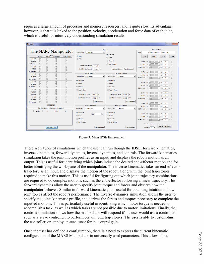
The main IDSE design environment is shown in Figure 3. The first feature of the IDSE is the
configuration specification tool, in which the user can change any of the joints positions along
their continuous domain, and lock any combination of joints. To help visualize what they are
doing, the students have access to two virtual-reality environments which show the manipulator
hardware: the visualization environment, and the simulation environment. The visualization
environment is a live static representation of the current configuration of the manipulator. It
shows exactly what the hardware would look like if the joints were in the positions specified.
The simulation environment shows the hardware as it goes through the motions that the user
defines. While similar in nature, the key difference is how they are used. The visualization
environment requires no rendering or high-processing of any kind, and can be run as a side
window while the user utilizes other aspects of the IDSE. The simulation environment, however,
Page 23.97.6
Page 7
requires a large amount of processor and memory resources, and is quite slow. Its advantage,
however, is that it is linked to the position, velocity, acceleration and force data of each joint,
which is useful for intuitively understanding simulation results.
Figure 3: Main IDSE Environment
There are 5 types of simulations which the user can run though the IDSE: forward kinematics,
inverse kinematics, forward dynamics, inverse dynamics, and controls. The forward kinematics
simulation takes the joint motion profiles as an input, and displays the robots motion as an
output. This is useful for identifying which joints induce the desired end-effector motion and for
better identifying the workspace of the manipulator. The inverse kinematics takes an end-effector
trajectory as an input, and displays the motion of the robot, along with the joint trajectories
required to make this motion. This is useful for figuring out which joint trajectory combinations
are required to do complex motions, such as the end-effector following a linear trajectory. The
forward dynamics allow the user to specify joint torque and forces and observe how the
manipulator behaves. Similar to forward kinematics, it is useful for obtaining intuition in how
joint forces affect the robot’s performance. The inverse dynamics simulation allows the user to
specify the joints kinematic profile, and derives the forces and torques necessary to complete the
inputted motions. This is particularly useful in identifying which motor torque is needed to
accomplish a task, as well as which tasks are not possible due to motor limitations. Finally, the
controls simulation shows how the manipulator will respond if the user would use a controller,
such as a servo controller, to perform certain joint trajectories. The user is able to custom-tune
the controller, or employ an auto-tuner for the control gains.
Once the user has defined a configuration, there is a need to express the current kinematic
configuration of the MARS Manipulator in universally used parameters. This allows for a
Page 23.97.7
Page 8
comparison to other manipulator configurations, as no other manipulator uses the MARS
Manipulator parameters to describe their kinematics. The standard way of expressing a robot’s
kinematic configuration is the set of Denavit-Hartenberg (DH) parameters. These parameters
have two conventions: standard[10]
and modified[11]
. Each convention has their own advantages
and disadvantages, but both are very similar and have almost equal capabilities. For this system,
the standard DH parameters are used.
Mapping from a serial manipulator to the standard DH parameters requires assigning several
coordinate systems to the manipulator, one for each unlocked joint. The procedure is as follows:
1. Find a point and unit-vector representing all z axes (axis of joint rotation or translation) for
the manipulator.
2. Find a point and unit-vector representing all x-axes (along the length for the link) for the
manipulator.
3. Update vectors from 1 and 2 to have a single point and two unit-vectors representing each
origin.
4. Assign DH parameters based on the coordinate systems.
Step 1:
The MARS Manipulator was designed such that the central axis of the manipulator intersects
every joint axis. Therefore, finding the point for each z-axis is done by transversing the central
axis until a joint is reached, and then the point is recorded. Similarly, once a point has been
recorded, the unit-vector for that axis is also recorded based on the knowledge of what joint has
most recently been reached. As the manipulator is traversed, the passive joints need to be taken
into account, as they change the direction of the manipulator’s central axis. Once a joint (active
or passive) was reached that is at a non-orthogonal orientation, the joint rotation is applied.
Orthogonal orientations are trivial, because orthogonal rotation matrices are well established. To
take into account non-orthogonal rotations, the Rodriguez’ rotation formula is applied[12]
:
R = uuT + (1 − uuT) cos θ + u sin θ; (1)
where: R: Rotation matrix to be applied
u: vector rotation is about
Θ: angle of rotation
u: skew symmetric form of u
Step 2:
The x-axis must intersect the current and previous z-axes. The x unit-vector is simply the cross
product of the z unit-vectors; the direction can be corrected later on. The following formulas are
used to compute this point. First, the 3×3 matrix [V] is found in (2):
[V] = [V1 V2 −V3] (2)
where V1, V2 and V3 are the unit vectors for the preceding z-axis, the current x-axis, and the next
z-axis respectively. Next, the scalar c is found in (3).
Page 23.97.8
Page 9
[abc] = [V]−1[P3 − P1] (3)
The point that describes the x axis is then computed in (4)
P2 = P3 + cV3 (4)
where P3is the point that describes the next z-axis. Note that a proof exists stating that the matrix
[V] is non-invertible if and only if V1 and V3 are parallel. If this is the case, the point P2 can be
taken as equal to the point P3. Further, the sign of b in equation 3 is applied to the vector V2 to
ensure it is pointing in the right direction.
Step 3:
This step is nearly trivial, as it is simply an organizational step in terms of the algorithm. The
unit-vectors remain unchanged, just stored in a single variable. The single point is taken as P2 as
it intersects both the x and z axes.
Step 4:
Once the origins are established, finding the DH parameters is now a simple task, following the
established procedure for the standard DH convention:
ai: The distance between origins i and i-1 along xi
di: The distance between origins i and i-1 along zi
αi: The angle between zi-1 and zi
θi: The angle between xi-1 and xi
The distance variables (a and d) are calculated along the unit vectors pointing to the next origin.
The angular variables are calculated using equation (5), where θ is the angle between two
vectors, x and y.
θ = cos−1[x ∙ y/(|x||y|)] (5)
Two solutions are present for this equation, but the second solution can always be rejected, due
to the nature of the vectors.
Once a configuration is designed by the user, the IDSE, along with other aspects of the Host PC
can download the configuration and the desired joint trajectories to the Target PC, such that they
can be run on the physical setup. The IDSE can monitor the sensor data from the manipulator,
and compare it to the data predicted by the simulation. As stated previously, the simulation is
used to protect the manipulator hardware by ensuring proposed actions are safe through
simulation results. However, the combination of the simulation and hardware serves another
educational purpose. This platform, through specific experiments, can highlight scenarios in
which a simulation performs similarly to a real-world setup, and scenarios where it does not.
This is a useful method of demonstrating the common shortcomings of a simulation in a practical
manner. The areas of interest for the MARS Manipulator platform in which the simulation and
the physical hardware differ include motor behavior at the extremes of their performance
Page 23.97.9
Page 10
capability and system compliance and flexibility, specifically from the harmonic drive
transmission systems.
As stated previously, the IDSE runs on the Host PC, which is remotely accessible via a remote
desktop protocol. From this, the user has control over the entire setup as if they were physically
sitting in-front of the robot. A visualization environment which shows a virtual representation of
the physical manipulator, along with video and audio streams provide the user with all the
information they need to effectively design and experiment with new configurations. This
remote-accessibility is controlled by the remote access portal.
5. Remote Access Portal
The architecture of the remote access portal for the MARS manipulator is depicted in Figure 4.
The portal consists of the following five modules:
Figure 4: Remote Access Portal Architecture
Remote Experiment Module:
The remote experiment module includes the IDSE, as explained earlier, and an additional
telecontrol interface layer on the host PC that allows it to be accessed by another machine via the
Remote Desktop Protocol (RDP). It, therefore, allows the end-user to take control of the host
machine, and by proxy, target machine as if they were sitting in front of the physical
workstations.
Scheduling Module:
The scheduling module manages when students may access the system. This module serves two
functions: the first is to guarantee that each student has access to the manipulator platform for the
needed time, as specified by course assignments and due dates; the second to provide a formal
time slot to discourage procrastination on the part of the student. Between schedule time slots,
the system is free to whoever logs on, on a first-come-first-served basis, which can be modified
Page 23.97.10
Page 11
to have a cap on students’ time if other students are waiting for the setup.
Telepresence Module:
The telepresence module provides the user with more information than a standard Remote
Desktop connection. Webcams and microphones on the experimental setup allow for video and
audio information to be transmitted real-time to the user. Further, communication tools can link
the student to the instructor, teaching assistants, and peers through a variety of methods, such as
instant messages, live audio or video chat.
Application Publishing Module:
The application publishing module is an extension of the telecontrol layer from the remote
experiment module. It allows students to access laboratory software and computing resources
from a centralized application server using RDP. The instructor can define a list of pre-approved
applications that students can run, along with a set of permissions for each application (i.e., what
the user can do with the application). Software usage is logged to a database so that the instructor
can monitor the utilization of resources.
Administration Module:
The administration module is a central web-based gateway that allows students, instructors and
teaching assistants to interact with each other and with the manipulator platform. This module
hosts administrative information such as course details, lab manuals and notes, student accounts
where they can store information privately or publically as they so choose, a list of all time slots
scheduled for the experiments and any other information and/or tools needed. The architectural
core of the administration module is the eCollaboration framework, which provides students
with contextual-based learning tools through a combination of communication and resource-
sharing components. Each student is given a personal site on the portal, analogous to a lab
notebook, for storing and managing their documents and laboratory work. Students can select
portions of their personal site to publish to the portal, or post on the internet. The entire
administration module is presented through a web interface layer, which is a collection of
dynamic templates that display various content sources using reusable wrappers called Web
Parts. Web Parts allow users to build a web their site and contribute from a collection of
distributed content and resource without having to script any code directly.
6. Expected Results
The MARS manipulator platform is scheduled to be implemented in a senior robotics course in
the near future. In preparation for this, several studies have been performed on other remotely
accessible systems using a similar framework and infrastructure. One area of interest is in the
student’s preference between using the experimental hardware proximally versus remotely. A
study involving an airfoil experiment in a wind tunnel was reported in [13], which used the same
portal architecture to allow proximal and remote access to the hardware setup. The students’
attitudes and performances were analyzed and discussed in [13]. Figure 5 shows the students’
preference on the method of utilizing the experimental hardware both before and after the
experiment. It reveals a lesser preference towards the proximal usage after the experiment was
Page 23.97.11
Page 12
undertaken compared with before the experiment was performed. Further analysis showed that
students who accessed the setup remotely would tend to prefer this mode more strongly versus
students who performed the experiment only proximally. It is expected that results of the MARS
Manipulator platform would enhance these results. Due to the higher complexity of the MARS
experimental hardware, however, it will be interesting to see if the students find the greater time
allocation of the remote system a benefit worth the trade-off of a physically removed experience.
Figure 5: Student’s preferred method of experimental access to airfoil experiment
To gain insight into how the increase in complexity will affect students’ preference for mode of
access, another study was conducted, comparing the results above to another more complicated
system. The second system is from a course which follows the previously mentioned course in
the engineering curriculum, and had experiments of slightly more challenging design and
comprehension; the concepts involved photoelasticity and supersonic flow and shockwaves.
These experiments used the same portal infrastructure. In [14], the results of this study showed
an 8% point overall reduction in preference of the proximal mode for the more complicated
experiment. While minor, it suggests that for more complicated setups, or perhaps with greater
student maturity and understanding, the remote accessibility may become more attractive. These
results are also to be examined using the MARS manipulator setup.
7. Conclusions and Future Work
Engineering education continues to progress alongside with the advancement of
telecommunications. Hence, there is a need for developing educational means that facilitate such
an emergence. In the field of robotics, a remotely-accessible, reconfigurable manipulator
platform would be an asset for teaching the related theoretical and practical notions. The MARS
Manipulator platform, as discussed in this paper, allows students to access and experiment with
various configurations of serial-link manipulators remotely and safely. The platform does not
require any proximal human operator to reconfigure, and can be fully utilized from any computer
capable of a remote connection.
Page 23.97.12
Page 13
The MARS Manipulator platform is to be used as a key laboratory means for a senior robotics
course. A series of experiments will be designed for the students to study the effect of kinematic,
dynamic, and control parameters in performing various tasks using different configurations. The
learning outcomes will be analyzed for two groups of students, those who have proximal access
to the platform and those who can only access the system remotely. These results will be
compared with experiments in [13] and [14] in which a similar system was utilized for different
experimental setups. It is also planned to invite students from other institutes to perform
experiments in association with their robotics courses and in collaboration with the local
students. The results of such inter-university learning collaborations will also be analyzed
through various studies.
References
[1] J. Cocota, H. Fujita, I. da Silva, "A low-cost robot manipulator for eductation", preceedings on Technologies
Applied to Electronics Teaching, IEEE. pp.164-169, 2012.
[2] C. Hsu, H. Chao “An autonomous mobile robot system for advanced microcontroller education.” Proceedings
of the 2009 Fifth International Joint Conference on INC, IMS and IDC, pp. 1709-14, 2009.
[3] M. Helander and M. Emami, "Engineering eLaboratories: Integration of remote access and eCollaboration",
Int. J. Eng. Educ., vol. 24, pp.466 2008.
[4] M.R. Emami, M.G. Helander, “Remote Access Laboratories for Engineering Education,” International
Conference on Engineering Education, Budapest, Hungry, July 27-31, 2008.
[5] D. Gillete, et al. “The Cockpit, an effective metaphor for web-based experimentation in engineering
education.” Int. J. Eng. Educ., vol 19, pp. 389-397, 2003.
[6] C. Kerer, et at. “ShareMe: running a distributed systems lab for 600 students with three faculty members.”
IEEE Trans. Educ., vol. 48, pp. 430-437, 2005.
[7] D. Deniz, A. Bulancak, and G. Ozean, "A novel approach to remote laboratories," in ASEE/IEEE Frontiers in
Education Conference, vol. 1, Boulder, CO, pp. T3E-8-T3E-12, Nov. 2003.
[8] L. Gomes, “Current Trends in Remote Laboratories.”, IEEE Trans. Industrial Electornics., vol. 56, no. 12, pp.
4744-4756, 2009.
[9] N. Kupp, Y. Makris, “Applying the Model-View-Controller Paradigm to Adaptive Test” IEEE Design&Test of
Computers, vol. 29, no. 1, pp 28-35, Feb 2012.
[10] Mark W. Sponge, Sethhutchinson and M. Vidyasagar Robot Modeling and Control, Wiley student edition,
2006.
[11] J.J. Craig, “Introduction to Robotics – Mechanics and Control”, Third Edition, Pearson Prentice Hall, 2005.
[12] R. Murray, Z. Li, S. Sastry, “A Mathematical Introduction to Robotic Manipulation”, Boca Raton, FL: CRC
Press, 1994.
[13] M.R. Emami, M.G. Helander, “The effects of computer interface on learning outcomes in remote access
laboratories”, Proceedings of the ASEE Annual Conference and Exposition, Austin, USA, 2009.
[14] M. Helander, M. Emami, “Engineering eLaboratories: Integration fo remote access and eCollaboration”
International Journal of Engineering Education, vol. 24, no. 3, 2008.
Page 23.97.13