A review of Bond-graph representation based design methodologies T.N.Madhusudan July 1995 CMU-R1-TR-95-28 The Robotics Institute Carnegie Mellon University Pittsburgh, PA 15213 Abstract Research in conceptual design methodologies based on bond graphs is reviewed. A brief summary of the bond-graph formalism is presented. Then each proposed design methodology in the design literature is analyzed with respect to the basic aim of the design problem and the bond graph notions that are used in the methodology. EhrtheF, the feasibility of using bond graphs to con~putationally support conceptual, parametric and configuration design tasks is discussed. This research is sponsored by the Office of Naval Research under contract no. ONR NOOO14-92-J-1396. The views and conclusions conkained in this document are those of the author and should not be in- terpreted as representing official policies, either expressed or implied, of the funding agency or the U.S. Government,
Transcript
A review of Bond-graph representation based design methodologies
T.N.Madhusudan July 1995
CMU-R1-TR-95-28
The Robotics Institute Carnegie Mellon University
Pittsburgh, PA 15213
Abstract
Research in conceptual design methodologies based on bond graphs is reviewed. A brief summary of the bond-graph formalism is presented. Then each proposed design methodology in the design literature is analyzed with respect to the basic aim of the design problem and the bond graph notions that are used in the methodology. EhrtheF, the feasibility of using bond graphs to con~putationally support conceptual, parametric and configuration design tasks is discussed.
This research is sponsored by the Office of Naval Research under contract no. ONR NOOO14-92-J-1396.
The views and conclusions conkained in this document are those of the author and should not be in- terpreted as representing official policies, either expressed or implied, of the funding agency or the U.S. Government,
Research in developing computational aids for electro-mechanical design address the follow- ing issues:
A representation for describing devices at various levels of abstraction to model device behavior, geometry, shape, form, function and material properties.
Algorithms that manipulate and process the representations to synthesize new devices by combining component devices, analyze devices for their properties and simulate the behavior of devices.
Since the number of design tasks to be resolved are numerous, the process of electro- mechanical engineering design has been classified into conceptual, configuration, parametric and detailed design phases which are organized hierarchically as shown in Figure 1. This classification enables one to address representation and algorithmic issues with respect to a particular design phase. Conceptual design is the early stage of the design process wherein physical concepts are synthesized to generate a prototypical device that can satisfy the de- sign specifications. Configuration design addresses the spatial organization of components that are assembled to generate a new device and the generation of physical embodiments for different components. Parametric and detailed design further refine the concept design with the use of analytical models to choose the different design parameters, study interactions among different design components and finalize the design for production. Numerous repre- sentations have been proposed to support the tasks in the above-mentioned design phases. A review of these representations and the design algorithms is presented in [l]. In this report, I focus on reviewing synthesis schemes that have been proposed used different aspects of a physical system modeling methodology called Bond graphs. There has been a recent surge in interest in using the bond graph formalism to support design tasks for a variety of reasons. I present the various ways in which the bond graph formalism may support efforts in building computational aids in the early stages of product design.
Bond graph based representations have been used to develop computational models for conceptual and configuration design phases. Research efforts that have used bond graph
based representations have attempted to enhance the bond graph formalism by defining new operations or used ad hoc annotations to the basic formalism. In this paper, I describe the bavic characteristics of bond graphs and then review the use of bond graphs in each design approach that uses bond graph based representations. This report attempts to illustrate how bond-graph based design representations have been used for design and assess why these methodologies have failed to provide answers to some design issues. I then discuss the characteristics of bond graphs and the corresponding design tasks they can support in a satisfactory manner.
In Section 2, I describe the basic formalism of bond graphs. I also describe the extensions t,hat ha>-e been developed by the bond graph research community to the basic formalism. In Section 3: I review each design research study that uses bond graphs with respect to the type of design specifications, the synthesis algorithm and the verification procedure to validate the designs. In Section 4, I conclude by proposing the use of bond-graph representations to address issues in conceptual and parametric design that utilizes the strengths of the bond- graph formalism.
2. A brief review of Bond graphs
In this section, I summarize the basic features of the bond-graph methodology. Extensive details are discussed in [2, 31. Bond graphs are a means of modeling and analyzing the dynamics of physical systems in an unified manner. The dynamics of physical systems are derived by the application of knstant-by-instant energy consemation. Systems are connected at places where power can flow between the systems. Such places are called ports and subsystems with one or more ports are called multkports. Each port of a system has four variables, namely,efort ( e ( t ) ) , flow (f(t)), efort integral (J e ( t )d t ) denoted as € ( t ) and flow integral (J j ( t ) d t ) denoted as F(t) . The power ( P ( t ) ) is equal to e ( t ) . f ( t ) . e ( t ) and f ( t ) are called power variables. The energy flowing through a port over a period of time E ( t ) is given by J e ( t ) . f ( t ) d t or J f ( t ) . d € ( t ) or J e ( t ) . d F ( t ) . &(t) and F ( t ) are called energy variables. A port in a system belongs to an energy domain. Power and energy variables can be identified for electrical, mechanical translation, mechanical rotation, thermal and hydraulic energy domains and are listed in Table 2. The first column lists the energy domain and the ensuing columns the effort, flow, power, effort integral, flow integral and energy variables of that energy domain. Energy domains that involve radiative transfer of energy (solar, light, acoustics, radiated heat energy) are not modelled though attempts have been made to extend the bond graph methodology to radiative phenomena. When two sub-systems are connected at their ports, the power and energy variables at each port are constrained to be equal. Power flows from one subsystem to another at any instant of time. It is an interesting fact that the only types ofphysical uariables that ape needed to model the dynamics of physical systems due to energy interactions can be described b y the power and energy variables e , j , &, and F.
The multi-port models function as components of subsystem and system models and are
Domain Effort Flow Power Effort Flow Integral Integral
Table 1: Energy and Power parameters
Energy
used to model physical eflects in a device and cannot be put into a one-to-one correspondence with physical components of a device. The port models are idealized mathematical versions of real physical embodiments such as masses, springs, and gears. Based on power and energy variables there are only a few basic types of multi-port elements that are required in order to model physical systems in a wide variety of domains. These models are described in the ensuing subsections. A bond graph consists of subsystems linked by bonds that denote power flow. All physical systems react to inputs and generate oatputs. Shown in Figure 2 is the schematic of a drive system for a telescope positioning system. Below the schematic is a word graph. A word graph identifies the different components of the schematic in terms of power flow between the components. Power flows from the electrical terminal to the motor and is converted to rotary power; then power flows through the shaft to the pair of gears that move the telescope load. Below the word graph is the bond-graph of the system. Bond graphs help in modeling the topological device structure of a physical system in terms of the connectivity of its components to obtain insight into the behavior of the physical system over time to different types of inputs to the system.
Many systems are so designed that only one of the power variables is important, so that a single signal is transmitted between two subsystems. For example, a pressure sensor in a pipe detects pressure and generates an electric voltage without consuming power from the fluid flowing through the pipe. The sensor extracts negligible power from the fluid. No information can really be transmitted at zero power, but practically speaking, information can be transmitted at power levels that are negligible compared to other system power levels. Such physical interactions involving information transfer accompanied by relatively negligible ammounts of energy transfer, are modelled as active bonds. These active bond models are easily incorporated into the simulation procedure for analyzing system dynamics using bond-graphs.
Figure 2: A Telescope position system
ONE PORT ELEMENTS
e R T c t I +
I TWO PORTELEMENTS
I THREE PORT ELEMENTS
Figure 3: Bond graph components
2.1. Bond-graph po r t models
The dynamics of physical systems can be modelled by building complex bond graphs based on component one-port, two-port and threeport elements. Complex systems can be described by topologies generated by inter-connecting the component port models.
A one-port device has a single power port as shown in Figure 3 and at the port a single pair of effort and flow variables exists. A one-port can be a very complex sub-system. An ordinary electrical wall-outlet can represent the port of a I-port in system analysis. The port actually connects to a vast network of power generation and distribution equipment, yet. from the system view point, a simple one-port model may suffice. There are three types of one-port component models. A one-port resistor(R) is an element in which the effort and flow variables at the single port are related by a static function e = G(f ) . The function is
Domain Electrical Hydraulic
Mech. Trans. Mech. Rot.
Table 2: One-port components
One-port components Resistor, Capacitor, Inductor
Accumulator, Valve, Flow obstructions Rigid bodies, Springs, dashpots
Flywheels, Torsion springs, rotary dash-pots
timeindependent and thus static. A one-port capacitor(C) is an element in which the effort and flow integral variables at the single port are related by a static function, e = G(;F). A one-port inertia (I) is an element in which the effort integral and flow variables at the single port are related by a static function, f = G ( E ) . Table 2 lists examples of one-port elements for different energy domains. Two other important oneports for purposes of analysis are the e$ort source, S,, and frow source, Sf. They are idealized versions of voltage supplies, current sources etc. In each case, an effort or flow is either maintained sensibly constant independent of the power supplied or absorbed by the source or is constrained to be some function of time. An electrical wall outlet can be modelled as a time-varying voltage source. The source models help to describe the nature of inputs (excitations) to physical systems.
Power flow in the single port of a one-port device is e(t).f(t) and flows into the device when positive and out of the device when negative. A resistor dissipates power and thus one cannot have negative power in the port of a resistor. Capacitors and inertial elements store energy and release energy depending on the physical state of the system modelled.
Two port devices have two ports as shown in Figure 3. At every instant of time e l ( t ) . f l ( t ) = ez(t).fz(t). There are a wide variety of two-port subsystems. The above equation implies that in a two-port system whatever power is flowing into one side of the 2-port is simul- taneously flowing out of the other side. To satisfy the power conservation relation in a physical two-port system, el may be related to ea and f1 may be related to fi. Another possibility is el may be related to f a and fl may be related to e2. A relation between the port variables that belongs to the first possibility is as follows: el = m.ez and f1.m = f z . This is called a transformer (TF) and rn is the transformer modulus. Examples of such two- ports are a gear-pair, a lever, an hydraulic ram etc. A two-port system with complicated constitutive relations is a slider-crank mechanism. The relations are el = R.Sin(7).e2 and fl.R.Sin(F) = fi where el is the torque, f1 is the angular velocity, e2 is the force on the slider and fi is the linear velocity of the slider. F is the angular displacement of the crank and R is the ratio of the connecting rod length to crank radius.
A two-port device that belongs to the second class is el = m.f2 and f1.m = e*. Such devices are called gyrators (GY). Examples are a DC motor and gyroscope. More complex relations can also be established between the power variables at the two ports.
Three-ports are power conserving elements which aid in distributing power flowing into
Figure 4: Coupled systems
one port to two other ports or summing up power flow into two ports into a single power flow as shown in Figure 3. The power conserving relation is e1(t) . f~( t )+ez( t ) . f i ( t )+e3(t) . f3( t ) = 0. Two trivial cases of three-port junctions can be defined. One primitive three-port has the following constitutive relations where el(t) = e z ( t ) = e3( t ) and fl(t) + j* ( t ) + f3(t) = 0 and is called the common-effort junction (-0-). Another primitive three-port device has the following constitutive relations where fi(t) = f i ( t ) = f3(t) and el(t) + e z ( t ) + e 3 ( t ) = 0 and is called the common-flow junction (-1-). It is important to note that there are infinite number of other constitutive relations that could be defined between the efforts and flows at the three ports that conform to the power conservation requirement.
The constitutive relations between the port variables (efforts and flows) have terms that depend on the physical embodiment of the device. In an electrical resistor (one-port), the constitutive relation is e ( t ) = R.i(t). The resistance R is dependent on the physical real- ization of the device. For example, the resistance of a wire depends on the wire-material. area-of-cross section etc. In a two-port device such as a gear-pair, the modulus rn is the gear ratio and depends on the ratio of the teeth, These physical embodiment terms are scalars and independent of position or orientation of the device.
2.1.1. Causality
Two subsystems that are connected, as shown in Figure 4, through power ports Le, share a power bond, are coupled with each other. In the figure a single power bond is shown separately as an effort and a flow coupling. An effort or a flow, not both, can he an input to system A or B and the other power variable becomes the output of the system. The effort variable from system A can be the output of system A and input to system B. The flow of system B can be the output of B and input to system A. This relation between input effort, output flow or vice-versa is called causality in bond-graph terminology. This notion of causality relates to the manner in which the mathematical relations between efforts and flows are used for computation. The notions of causality is used to enable computation and resolve algebraic loops when solving systems of algebraic or differential equations. This notion of causality is extended to one-port, two-port and three-port component models. I will describe the notions of causality for one-port models only. Causality notions regarding two-port and three-port models are described in [2].
A resistor can be represented by two equivalent relations, namely, e = @(f) or f = @-'(e)?
where the convention is that the variable on the left of the equality sign represents the output (dependent variable) and that on the left is the input (independent variable). Physically given e or f, the rest of the port variables are determined. Now consider a capacitor with constitutive equations which are equivalent, namely, e = W1(J f ( t )d t ) or f = 2 [@(e)]. The first equation denotes integml causality and the second deriwatiwe causality. Similarly an inertial element has the equations,f = W ' ( J e ( t ) d t ) or e = [@(f)]. It is of interest that physical processes can only be realized by integral causality. For example to stretch a spring you need to apply a force (integral causality). You cannot generate force in a spring by stretching a spring i.e. the force in the spring is not an after effect of stretching (derivative causality). The force here refers to force input on the spring. One should not confound the input force with the force that is generated in a spring on stretching. This resultant force is in a direction opposite to the force that initially stretched the spring and is thus different.
Using these primitive port models, a variety of systems can be modelled and analyzed. Different topologies of these port models can be used to model complex networks of interact- ing physical systems. The bond-graph for the telescope drive system is shown at the bottom of Figure 2.
2.2. Analysis of physical systems using bond-graphs
Bond-graphs of systems (including active bonds) can be algorithmically transformed into a system of statespace differential equations as described in [2]. The differential equations are solved numerically to obtain the time behavior of the state variables. The differential equation models can be used to obtain free response (no inputs to the system) and forced response of systems (inputs to the system). This procedure is equivalent to generating block diagrams in a control-engineering framework and obtaining the transfer functions. The state- space system of differential equations can be analyzed to obtain frequency response, phase response, power spectra and other dynamic characteristics of physical systems.
The order of the differential equations depends on the capacitors and inertial elements in the bond-graph models with integral causality. Capacitors or inertial elements with deriva- tive causality do not contribute to the order of the differential equation. The dynamics of the physical systems depends on the number of capacitive and inertial elements with purely integral causality.
Bond graphs have been primarily used to model and predict behavior of physical sys- tems across multiple energy domains. There is a vast literature on bond graph models for a variety of electromechanical devices 141. The bond graph method can be viewed as a gener- alized version of Kirchoff's laws across different energy domains. Further bond graphs can be algorithmically transformed into state-space or block diagram representations to enable synthesis of control systems. Further the bond graph methodology is closely related to the Hamiltonian and Lagrangian schemes of variational calculus and behavior prediction using energy minimization[?]
2.3. Summary of bond-graph characteristics
I summarize the features of the bond graph methodology with regard to their advantages and drawbacks from the viewpoint of design. Bond graphs as a modeling mechanism for performing dynamic analysis of physical systems are useful for the following reasons.
Bond graphs model physical effects as energy interactions in terms of four dynamic variables. Bond graphs can model interactions between different energy domains.
Bond-graphs use finite set of component models to model dynamic behavior for complex systems.
Mathematical relations between the port variables consider the effect of geometry and material of a physical embodiment on dynamic behavior. Bond-graph modeling as pre- sented earlier deals only with scalars. Position or orientation dependent parameters i.e. parameters related to spatial coordinatc systems such as velocity in the x-direction(v,) can be considered by choosing a suitable coordinate system to express the constitutive relations. Further bond graph elements can be used to model distributed, spatially dependent parameters as f i e ld effects.
The translation of a bond graph to a system of linear or non-linear differential equa- tions provides the ability to compute the dynamics of physical systems in great detail. System behavior can be predicted using numerical methods. Further the system of equations is greatly simplified when one port systems are not considered and only nominal behavior is required. One port systems are the energy storers and dissipators that capture the history of the system and therefor introduce integrality terms in the system of equations. One-port systems act as memory storage components and intro- duce time delays and related system modeling issues that modifies the nominal ideal behavior without these elements.
Modeling in terms of bond-graph elements helps one to focus on modeling the phys- ical effects without bothering about the computational issues such as generating a consistent system of equations.
The graph-based scheme of bond graphs allows development of well-defined synthesis A algebraic theory of bond graphs and its algorithms and their rigorous analysis.
relation to linear network theory is provided in [5 , 6, 7, 81.
The expressive power of bond graphs are also limited in certain ways such as:
Bond graph models that deal with multiple energy interaction such thermo-fluid in- teractions, magneto-fluid interactions etc. are highly complex. Further the systems of equations obtained from these models are complex and require intensive computation.
Bond graph models are lumped parameter (no spatial information) models. Bond graphs do not provide a formalism to generate shapes, though shapes and geometries can be described in terms of lumped descriptors.
Bond-graphs cannot model non-energic interactions between subsystems i.e. dynamic interactions without power flow. The dynamics of the robot when it is grasping and moving an object can be modelled using bond- graphs. When the object is released, the initial system decouples into two non-energy- interacting subsystems. The dynamics of this process cannot be modelled using bond- graphs. These interactions occur in systems such as part-feeding systems and material handling systems. Such interactions are discussed in 191.
Consider a pick and place robot.
2.4. Bond graphs a n d design
Bond graphs are primarily used for dynamic analysis of complex physical subsystems. The ability to model behavior of physical systems over time should enable the use of bond graphs for performing behaaaor synthesis. Behavior refers to the time-course of parameters used to describe physical systems. Behavior synthesis refers to assembling component models that encapsulate particular behaviors by connecting them at their ports to generate an overall dynamic behavior that meets the design specifications. Bond graphs enable one to capture the time-variant behavior of physical embodiments and should support design of systems with specifications that. are based on device behavior over time. Bond graphs do not provide much insight into physical systems that are static (do not vary with time) such as engineering structures like buildings, bridges and beams. Bond graphs though can be used to study dynamic effects of earthquakes, winds, etc. on the engineering structures. Bond-graphs can be used to model physical systems at different levels of granularity and detail. Complex systems can be modelled hierarchically with each level at a greater detail than the superseding layer, Computational models of synthesis can use such hierarchical models to recursively define and refine physical systems as design specifications are obtained in increasing detail during computation. Bond graphs provide a scheme to model both signal and power devices at a convenient level of abstraction in terms of energy interactions instead of detailed physical laws represented as equations. Bond graphs cannot be used t o do embodiment design wherein one is concerned with design specifications concerned with the position and orientation of the physical embodiment. Thus bond graphs cannot be used for spatial form design. New representations are required to import spatial distributions of form into the bond graph formalism.
3. Reviews of research
In this section, I summarize design methodology proposed in design theory literature with respect to the design specifications, the synthesis and verification procedures. The discussion for each design approach describes what aspect of the bond graph formalism was used, the
4 P(t) ; i - ?
: ~
W - g r a p h Specification
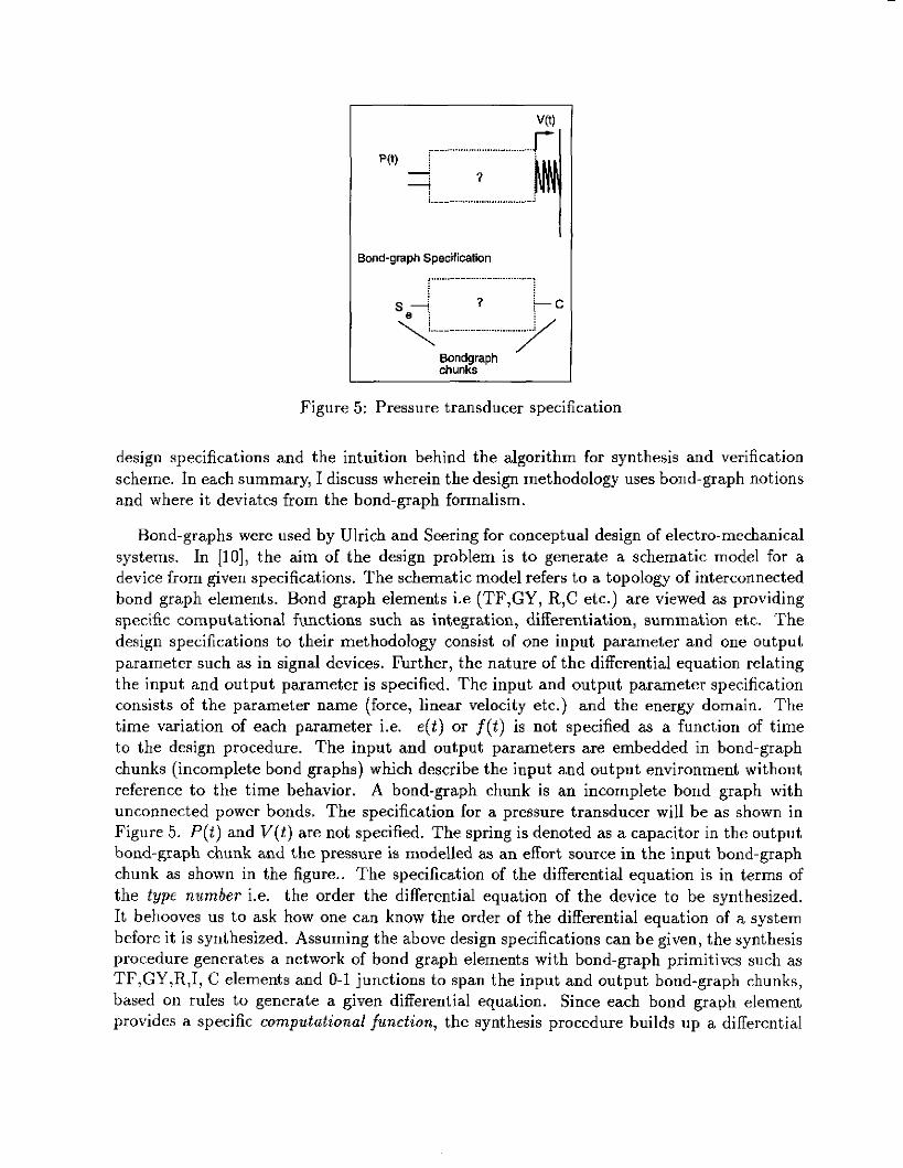
Figure 5: Pressure transducer specification
design specifications and the intuition behind the algorithm for synthesis and verification scheme. In each summary, I discuss wherein the design methodology uses bond-graph notions and where it deviates from the bond-graph formalism.
Bond-graphs were used by Ulrich and Seering for conceptual design of electro-mechanical systems. In [lo], the aim of the design problem is to generate a schematic model for a device from given specifications. The schematic model refers to a topology of interconnected bond graph elements. Bond graph elements i.e (TF,GY, R,C etc.) are viewed as providing specific computational functions such as integration, differentiation, summation etc. The design specifications to their methodology consist of one input parameter and one output parameter such as in signal devices. Further, the nature of the differential equation relating the input and output parameter is specified. The input and output parameter specification consists of the parameter name (force, linear velocity etc.) and the energy domain. The time variation of each parameter i.e. e ( t ) or f ( t ) is not specified as a function of time to the design procedure. The input and output parameters are embedded in bond-graph chunks (incomplete bond graphs) which describe the input and output environment without reference to the time behavior. A bond-graph chunk is an incomplete bond graph with unconnected power bonds. The specification for a pressure transducer will be as shown in Figure 5. P ( t ) and V(t) are not specified. The spring is denoted as a capacitor in the output bond-graph chunk and the pressure is modelled as an effort source in the input bond-graph chunk as shown in the figure.. The specification of the differential equation is in terms of the type number i.e. the order the differential equation of the device to be synthesized. It behooves us to ask how one can know the order of the differential equation of a system before it is synthesized. Assuming the above design specifications can be given, the synthesis procedure generates a network of bond graph elements with bond-graph primitives such as TF,GY,R,I, C elements and 0-1 junctions to span the input and output bond-graph chunks, based on rules to generate a given differential equation. Since each bond graph element provides a specific computational function, the synthesis procedure builds up a differential
equation that matches the specification in terms of these elements. Since a single differential equation can model a variety of systems, heuristics are used to curtail search. This synt.hesis procedure is equivalent to generating an analog computer model of the differential equation. A verification scheme that only checks the type number is provided. Since only single input and output parameter are given, only one differential equation relating the two parameters can be generated. The order of this differential equation i.e. the type number is matched with the specification. If type numbers are different, one can increase or decrease the order of the differential equation by adding I or C elements in integral causality or derivative causality. These are called the modifying rules.
This design specification is different from the one required to design a power transforming device consisting of a one input power port and one output power port. Specification for such a device consists of effort and flow variable specifications at both input and output ports. Therefore the methodology proposed by Ulrich cannot sgnthesize power transforming dewices. The synthesis procedure proposed in [lo] makes an implicit assumption that the design space of behaviors defined by a network of bond graph elements is smaller than the physical embodiment. This hypothesis is based on the finite number of one-port, two-port and three-port component models necessary to model the dynamics of systems. This is not true since t,here are infinite functional relations between the port variables of e x h one-port, two-port, or three-port element. The aim of Ulrich’s procedure is to generate schematics so as to bound the embodiment design space. A variety of schematic networks can be generated because of the infinite number of elements that can be added using the junction elements. Further, many physical systems are driwen by inputs and behave in different ways for different inputs. For example, a pair of gears may be used to transmit rotary motion or oscillatory motion depending on the input at the driving shaft. The proposed synthesis procedure does not consider the time nature of the inputs and outputs of the physical systems to be synthesized. At the schematic level, the procedure does not deal with parametric aspects of the models. The verification procedure is dependent only on the order of the differential equation without giving insight into t,he structure of the differential equation.
In [ll], the authors address the issue of functeon sharing at the embodiment level. A single physical entity can have multiple behaviors. For example, a piece of metal wire may be modelled as a resistor, inductor or a capacitor. Assuming that a physical entity consisting of physical components is generated and each physical component provides an unique behavior to the designed entity (though each component has multiple behaviors), the extraneous behaviors of a physical component can be used as a szlbstitute for a behavior provided by another physical component. This process reduces the number of physical components in the designed entity. Ad hoc structural modification rules are suggested to substantiate the example wherein bond graph elements are combined to generate device topologies with smaller number of components. Reduction in the number of physical components does not imply simplification of a design. As behaviors are shared, it is increasingly difficult to diagnose errant behavior and localize faults in a mal- functioning device. Unnecessary couplings may be introduced between components. Them i s a trade-off between physically simplifying embodiments and increasing complex interaction of behaviors.
This is illustrated by a fluid network example.
Figure 6: A spring model with spatial connectivity information
Rinderle et al.[l2,13,14] have used bond graphs primarily to perform embodiment design. They view design as a transformation process from the schematic level (Le. the topology of bond graph elements) to the embodiment level. In [13], the design specification consists of a bond graph that spans input and output. An example from the domain of gear design is illustrated. In the design specification, it is assumed apriori that gears are required. h transformer (TF) specification, i.e. a gear pair, is embellished with ad hoc spatial informa- tion on the collinearity and orientation of shafts. Also given as a specification is the required gear ratio and the gear ratio is implicitly assumed to be constant with time. Components represented with attributes similar to the specifications are retrieved from a database. The spatial specifications are used in an ad hoe manner to prune the search for the right combina- tion of components. Matching of components is based on their geometric attributes rather than their “behavior”. Neither the issue of generating embodiments for non-transformer bond graph elements nor parametric design is addressed. The problem that a single gear ratio can be generated by multiple tooth ratios leading to different gear pair embodiments is not addressed.
In 1121, the initial graph specification is modified by defining graph operations that add bond-graph elements in a manner similar to [IO]. They view bond graph elements as defining a behavorial description language or grammar. Then design can be viewed as the process of transforming an initial graph (a sentence in the grammar) to a final graph through application of a sequence of productions. They describe a production to generate gears in the grammar. This transformation is facilitated since gears have a linear constitutive relation between input and output. Productions based on R,C,I,-O-,-l- and GY elements are not defined and it is unclear how this approach may be extended to capture non-linear input output behavior. Further, i t is not obvious how one can represent the variety of time histories of inputs and outputs in devices. In [14], an effort is made to use bond-graphs for embodiment design by enhancing the representation. A notion that models a spring as a two port device because it has two ends is used. So a spring, which is a capacitor element, is modelled as a two port device as shown in Figure 6. Bond graph chunks in a similar manner are developed for various kinematic connections. Each chunk is annotated with position and orientation information. Complex devices are assembled (by the user) from such chunks and the complex network is reduced to generate differential equations for analysis. No analysis results are presented. All the above approaches do not deal with the issue of timevariance of physical parameters of devices. Each approach rapidly descends to the embodiment design problem and addresses
Bond graphs enable one to describe device structure in terms of a graph of primitix- elements (static representation) and predict behavior of such a structure to time varying inputs.
It is also reported in literature that bond graphs do not address the laws of conservation of momentum or the laws of thermodynamics. Nothing could be further from the truth. By conservation of the effort integra1 variable, one can track the flow of generalized momentum in mechanical systems as mechanical momentum, as flux conservation in electromagnetism and pressure momentum in electromagnetic systems. Further, even the conservation of charge is exhibited in the conservation of the flow integral variable in the hydraulic domain. Also, one can see that the laws of thermodynamics are satisfied and can be checked. Considerthe second law of thermodynamics, wherein, U = Q - P V , (U is the internal energy, Q is the input energy, P is the pressure (effort variable) and V is the volume (flow integral variable)). This equation is valid for all systems as indicated in [20], wherein, the effort and flow integral variables are replaced by variable from the corresponding energy domains.
Finally, why could the bond graph formalism be useful ? First, they are at a convenient level of abstraction with enough semantic content. They are not too detailed such as the equations of physical laws, which require further interpretation to have any semantic mean- ing. The graph based representation supports different kinds of graph based manipulations and computations. An often overlook aspect is that the bond graph formalism provides a convenient link to analysis and simulation so that any designs generated may be verified. Finally, they provide a convenient bridge between qualitative and quantitative descriptions of the physical phenomena. Bond graph based representations are well suited for synthesis procedures where design specifications relate time varying inputs and outputs and a network (topology) of primitive elements is desired. Computational design methodologies that aim to perform design by recursively descending from conceptual to parametric to embodiment synthesis may benefit from the ability to describe a large design space in an efficient man- ner through bond-graphs at the conceptual level. Further, the bond graph framework fits well withing th systematic principles of design proposed in [21, 22, 23, 241 Further work is required to import spatial characteristics into the bond graph system so as to enable concur- rent behavior-shape synthesis. In [25], we have developed a synthesis scheme using a bond graph based design representation. Future research aims at addressing some of the concerns discussed above.
References
[l] S.Finger and J.R. Dixon. A review of research in mechanical engineering design. Re- search in Engineering Design, 1(1), 1989.
[Z] D. Karnopp and R. Rosenberg. System Dynamics: A Unified Approach. John Wiley Sons, New York, 1975.
[3] Margolis D.L. Rosenberg, R. and Karnopp. D. System dynamics: a unijed approach. Wiley, New York, 1990.
design issues that are spatial in nature. Also design specification is given in terms of a particular class of devices e.$. gears. Verification at the behavior, parametric or at the embodiment level is not discussed.
Dixon and Welch (151 use bond-graphs to generate physical embodiments from initial specifications that are similar to [lo]. No type number is given nor the input and output are represented as chunks, The bond graph representation is annotated with notions of vectors, orientation and position information. Given the input-output parameter types and energy domains, an initial graph is retrieved from a library. An infinite number of graphs can be formulat.ed as the initial graph and they do not describe their scheme for generation of initial graphs. The design process deals with modifying the initial graph by adding new bond-graph elements in a manner similar to [lo, 121. Parametric values for the power and energy variables are computed based on the constitutive relations of the components. They attempt to extend the representation for design of static structures such as a hinged pin.
In related work, Prabhu and Taylor[lG, 17, 181 present theoretical results on the types and characteristics of power topologies of devices. Graph-theoretic formulations and results are presented regarding the structure of power topologies. They also aim to embellish the bond graph representation with spatial information to aid embodiment synthesis. They do not present any explicit design methodology with regard to design specifications, synthesis or verification procedures. Hauck and Taylor [19] attempt to delump the bond graph rep- resentation by defining surface and volume integrals based on the material distribution i.e. embodiments. Only one-port R,C, and I elements can be modelled in this manner while the issue of representing 2-ports and 3-port devices is not discussed. It is also not clear how such a representation might enable a synthesis algorithm.
4. Clarifications and issues for further research
We focus our discussion on the inconsistencies and ambiguities of the foregoing methods. Then we discuss some fallacies regarding bond graphs that we have noted in the design literature. Finally, we highlight how bond graphs can enable development of representations for synthesis.
The methodologies reviewed above exhibit the following features:
Device behavior over time,i.e. in terms of input and output parameters is not addressed in representation of design specifications or the device.
The methodologies aim to perform embodiment design as early as possible in the design process and thus the attempt to overload the bond graph representation using ad hoc annotations. Bond graphs do not support shape generation.
Since bond-graphs were never meant to represent the embodiment level, it is futile to gain insight into issues regarding embodiment synthesis i.e. spatial issues, using bond-graphs.
[4] Rosenberg R.C. Breedveld, P.C. and T. Zhou. Bibliography of bond graph theory and applications. Journal of the Franklin Institute, 328(5/6):1067-1109, 1991.
151 S.H. Birkett and P.H. Roe. The mathematical foundations of bond graphs-i. algebraic theory. Journal of the Franklin Institute, 326(3):329-350, 1989.
[6] S.H. Birkett and P.H. Roe. The mathematical foundations of bond graphs-i. duality. Jovrnal of the Franklin Institute, 326(5):691-708, 1989.
[7] S.H. Birkett and P.H. Roe. The mathematical foundations of bond graphs-i. matroid theory. Journal of the Franlin Institute, 327( 1):87-108, 1990.
(81 S.H. Birkett and P.H. b e . The mathematical foundations of bond graphs-i. matrix representation and causality. Journal of the Franklin Institute, 327(1):109-128, 1990.
[9] K. Hogan. Modularity and causality in physical system modelling. J. u f Dynamic Systems,Measurement, and Control, 109(4):384-391, Dec 1987.
[IO] K. T. Ulrich and W. P. Seering. Synthesis of schematic descriptions in mechanical design. Research in Engineering Design, 1( l), 1989.
1111 K. T. Ulrich and W. P. Seering. Function sharing in mechanical design. In 7th National Conference on Artificial Intelligence, Minneapolis, MN, August 21-26 1988. AAAI-88.
1121 J. R. Rinderle Finger, S. A transformational approach to mechanical design using a bond graph grammer. In Proceedings of the First ASME International Design Theory and Methodology Conference, September 1989.
[I31 S. Hoover and J.R. Rinderle. A synthesis strategy for mechanical devices. Research in Engineering Design, 1:88-103, 1987.
[14] J.R. Rinderle and L. Balasubramaniam. Automated modeling to support design. In Second ASME Design Theory and Methodlogy Conference. ASME, 1990.
[15] R. Welch and J.R. Dixon. Conceptual design of mechanical systems. In Design Theory and Methodology, volume 31, pages 61-68, 1991.
[16] D. Prabhu and D. Taylor. Some issues in the generation of the topology of systems with constant power flow input-output requirements. In ASME Design Automation Conference. ASME, 1988.
[17] D. Prabhu and D. Taylor. Synthesis of systems from specifications containing orien- tations and positiobns associated with generalis4 flow variables. In ASME Design Automation Conference. ASME, 1989.
[18] D. Prabhu and D. Taylor. On deriving supported configurations of mechanical systems from their functions. In First Intl. Worbhop on Form Methods in Engg. Design, Manfg., and Assembly, 1990.
[19] P. Hauck and D. Taylor. Deriving physical constraints from functional topologies. Re- search in Engineering Design, 2:81-92, 1981.
[20] Feynman R.P. Leighton, R. and M. Sands. The Feynman Lectures on Physics Volume-I. Addison- Wesley, 1965.
[21] G. Pahl and W. Beitz. Engineering Design. Springer-Verlag, London, 1988 edition, 1988.
1221 W. Gosling. The design of engineering systems. Wiley, 1962.
[23] W. E. Eder and W. Gosling. Mechanical System Design. Pergamon, Oxford, 1976.
(241 V. Hubka. Theory of Technical Systems: A total concept theory of Engineering design. Springer-Verlag, Berlin, 1988.
[25] T.N.Madhusudan. A bond graph based approach to case-based synthesis. Technical Report CMU-RI-TR-95-29, The Robotics Institute, Carnegie-Mellon University, Pitts- burgh? PA 15213, July 1995.