Page 1
A review of the tunable microinductors
Dong-Ming Fang1,Hai-Xia Zhang
1, Norman C. Tien
2
1National Key Laboratory of Nano/Micro Fabrication Technology,
Institute of Microelectronics, Peking University, Beijing 100871, China 2Department of Electrical and Computer Engineering,
Case Western Reserve University, Cleveland, OH 44106, USA
Abstract: Radio frequency (RF) tunable inductors have a major role in current situation where
compact designs with high performance are demanded. The capability of the tunable inductors, to
tune the inductance with high or proper quality factor (Q-factor), has been a good advantage in the
tunable systems to the designers rather than to use the tunable capacitor which exhibit poor
reliability and require large die area. Tunable inductor could be a candidate to save die area and a
solution for designs of the tunable systems with large tuning range for portable communication
systems in the future. Therefore, a review of the tunable inductors from a device perspective is
provided. Based on their tuning mechanism, the tunable inductors can be classified into four
categories: discrete tuned, metal shielding tuned, magnetic core tuned and coil-coupled tuned. This
paper summarizes the major contributions to the tunable inductors and discusses the advantages
and disadvantages of these contributions. Some considerations and results on fabrication,
operation, comparison and application of the tunable inductors are presented.
Keywords: tunable inductor, tuning ratio, tuning range, inductance, quality factor, MEMS
1. Introduction
Radio frequency microelectromechanical system (RF MEMS) is a technology that enables the
batch fabrication of miniature mechanical structures, devices, and systems for microwave and
wireless communication applications.There are four basic RF MEMS components have been
reported so far: (i) the switch; (ii) the (tunable) capacitor; (iii) the (tunable) inductor and (iv) the
antenna. These four components can be used to realize high performance and digitally-controlled
components (e.g. RCL lumped-elements), circuits (e.g. attenuators, phase shifters, impedance
tuners, filters, oscillators) and subsystems (e.g. T/R modules and antenna arrays). By far, the most
common actuation mechanism is electrostatic, followed by piezoelectric, magnetic and
electrothermal. RF tunable capacitors and inductors can be used to form tunable filters, low-noise
voltage-controlled oscillators (VCOs), self-adjusting matching networks or power amplifiers. In
general, the tunable capacitors have better tuning range and quality factor(Q-factor) than tunable
inductors, however, the tunability of the tunable inductors provides additional functionality,
design flexibility and robustness, which make the tunable inductors promising applications in the
field of portable communication systems The tunable inductors can be divided into four categories:
discrete tuned (DT), metal shielding tuned (MST), magnetic core tuned (MCT) and coil-coupled
tuned (CCT). The discrete tuned inductor often uses microswitches [1-4] or microrelays [5, 6] to
increase or decrease the effective coil length of the inductor, but the combination of the
microswitches or micorelays will reduce the Q-factor of the inductor. The metal shielding tuned
inductor is realized using moveable metal structure with large range, resulting in the magnetic flux
of the inductor changed [7].The magnetic core tuned inductor is realized using solenoid inductor
imbedded with magnetic-core conductor whose permeability can be changed when applying
Corresponding author. Tel: +86 10 62752536-17, Fax: +86 10 62751789, E-mail: [email protected]
Page 2
magnetic filed [8, 9]. The coil-coupled tuned inductor mainly adjusts its mutual inductance
between the primary coil and the secondary coil of the inductor [10-12]. Key features, measured
performance characteristics and various applications based on their performance of the reported
tunable inductors are summarized (and referenced) in table 1. Tuning types and configurations
vary widely. Tunable inductors with discrete tuned, metal shielding tuned, magnetic core tuned
and coil-coupled tuned have been reported are discussed further below.
Table 1 Tunable microinductors.
Author and year Tuning
type
Tuning ratio@
Frequency(GHz)
Q-factor@
Frequency(GHz)
Fabrication
process
Other
information
Applications
Zhou [13],1999 DT 129.2 [email protected]
[email protected]
SBM area
3150μm×930μm
, DV: 20V.
n/r
Park [1],2004 DT [email protected] [email protected] CMOS area
206μm×217μm
driven voltage
1.8V
n/r
Balachandran[4],2004 DT 1.64@25 n/a MEMS DV:25-35V n/r
Mina[14], 2007 DT 1.66@5 45@5 post-CMOS-
compatiable
DV:40V n/r
Zekry [15],2007 DT [email protected] [email protected] MEMS area
620μm×620μm
n/r
Okada [17],2006 MST A:[email protected]
B:2.11@2
A:[email protected]
B:50.1@2
MEMS area about
460μm×460μm
VCO:TR 146.5%
Sugawara[19],2004 MST [email protected] [email protected] 0.35μm
CMOS
area about
400μm×400μm
VCO:TR 123.7%
Ito [20],2005 MST [email protected] About [email protected] 0.18μm
CMOS
area about
400μm×400μm
VCO:TR 72%
Vroubel [22],2004 MCT [email protected]
1.54@1
1.25@2
Less than 2@? n/r FM core area
about
200μm×50μm
n/r
Salvia [8],2005 MCT 1.17@5 5~10@over 5 BiCMOS
n/a n/r
Sarkar[25],2005 MCT 1.24@1~5
[email protected]
[email protected]
[email protected]
n/r
n/a n/r
Lubecke [26],2001 CCT 1.22@15GHz About
13@2GHz
MUMPS n/a n/r
Zine-El-Abidine[27],
2003
CCT 1.13@2~5 n/a MUMPS n/a n/r
Zine-El-Abidine[11,12],
2005
CCT 1.43@over 2 25@10 SBM SRF:35GHz n/r
Zine-El-Abidine[28],
2007
CCT 2.1@ n/a 5@3 MetalMUMPs n/a n/r
Page 3
Fukushige [29],2003 CCT 1.03@2 Less than
[email protected] ~16
MEMS n/a n/r
Chang[32],2006 CCT [email protected] ~5 [email protected] MEMS DV:0~2V n/r
Dell [33],2002 CCT [email protected] n/a BM n/a n/r
Sugawara [16],2004 MST 2.11@2 50.1@2 MEMS n/a VCO:TR 146.5%
YANG [38],2006 CCT n/a n/a 0.18μm
CMOS
n/a VCO: TR 106.5%
Worapishet [39],2002 CCT n/a n/a BiCMOS n/a Filter: TR 171.4%
Lin [3],2005 DT [email protected] [email protected] CMOS n/a LNA: TR 174.2%
Sugawara [41],2005 MST 1.4@2
3.5@2 0.18μm
CMOS
n/a LAN:
TR 188.2%
Tassetti[42],2004 CCT 2@1~5 n/a MEMS n/a phase shifter: 25°
at 5GHz and 48° at
8GHz
n/a: not applicable; n/r: not reported; SBM: surface and bulk micromachining; SRF:
self-resonance frequency; DV: driven voltage; TR: tuning range
2. Discrete tuned inductor
The electrical model of the discrete tuned inductor is usually described as shown in Fig.1.
When the switches at port two are open, the inductance is L1. When the switches at port two are
closed, the length of the coils at port two will be changed and the different mutual inductance will
affect the effective inductance Leq. Leq can have n2 discrete values depending on which coil at port
two is switched on. The effective inductance Leq and the effective resistance Req can be written as
2 2 2
1 2 2 22
(1 )n
n n neq
i n n
k LL L
R L
(1)
2 2
11 2 2 2
2
nn n n n
eq
i n n
k R L LR R
R L
(2)
where Ln is the inductance of the coil at port two, kn is the coupling coefficient, Rn is the series
resistance of the coil at port two and the contact resistance of the corresponding switch, δn is 1
when the switch is at the „on‟ status and 0 when it is at the „off‟ status. To achieve high Q-factor,
Rn must be much smaller than the reactance of the coil (Ln•ω ).
Fig.1 Electrical model of the discrete tunable inductor.
Zhou [13] fabricated a tunable inductor, as shown in Fig.2, with digitally controlled microrelays
by using combined surface and bulk micromachining technology. The microrelays used TaSi2/SiO2
layers as the bimorph cantilever beam, aluminum as sacrificial layer. The combined thermal and
electrostatic mechanism made the possibility of the gold-to-gold contacting. In order to reduce the
losses of the parasitic oxide capacitances and the eddy current loss in the substrate, the silicon
Page 4
substrate under the inductor was etched. By using the planar spiral coil and four microrelays, the
inductances of the tunable inductor varied from 2.5nH to 324.8nH to obtain sixteen different
inductance values. The self-resonant frequencies were 1.9 GHz and 4.6 GHz, while the quality
factor (Q-factor) was 1.7 (f = 530 MHz) and 3.3 (f =1.6 GHz), respectively. The lowest thermal
power was 8mW and the electrostatic driven voltage was 20V. Because of the limitation of the
mechanical self-resonance, the highest operation frequency of the microrelays was 10 kHz, which
leaded the tunable inductor to be used in the portable mobile communication systems in the range
from 0.5GHz to 1.6GHz. Moreover, the whole device was 3150μm×930μm which is relatively
larger compared to other tunable inductors. Because the fabrication process combined surface and
bulk micromachining technology, seven masks was used, resulting in the complexity and
incompatibility with IC technology. Park [1] fabricated the stacked spiral inductor using standard
CMOS process and the inductor was connected with MOSFET switch. When the status of the
switch varied, the inductance of the inductor changed. The measured results showed that the
inductances changed form 8nH to 23nH at the frequency of 2.4GHz. The resonance frequency of
the proposed inductor decreased from 3.9 to 3.6 GHz for the three-stacked inductor and from 6.8
to 6.4 GHz for the two-stacked inductor. The stacked inductor had a comparable Q-factor 4.8 at
the frequency about 1.5 GHz. Compared to the traditional single-layer inductors, because the
structure of the inductor was stacked, fifty percent of the chip area was saved. However, because
of multi switches, which induced parasitic capacitances, resulting in the decrease of the
self-resonant frequency and thirty percent of the Q-factor. Balachandran et al. fabricated MEMS
tunable inductors using DC-contact switches [4]. In their fabrication process, PMMA was used as
sacrificial layer and resistive SiCr was used to provide DC-bias. Experimental results show that
the inductance value can varies from 0.34nH to 0.56nH at 25GHz, that is, the inductance ratio is
of 1.64. However, the measured insertion loss for the switch-actuated state had a difference of
0.3dB.
In 2007, Mina fabricated a novel switch controlled tunable inductor [14]. The switched tunable
inductor was fabricated by using a post-CMOS-compatiable process. In order to decrease the loss
of the Si substrate, the backside of the substrate was selectively etched under the device. As shown
in Fig.3, four discrete inductance values were obtained by using the contacts of the switch to
contact/leave the primary and the secondary coils of the inductor. The actuation voltage of the
switch was 40V. When the switch was off, the inductance was 1.01nH. Through the switch, the
maximum tuning range of the tunable inductor was 40% at 5GHz and the corresponding Q-factor
was 45. The authors pointed out that the Q-factor of the inductor didn‟t decrease obviously after
package. The key point of the structure was the switch. The switch used silver as the cantilever,
driven by electrostatic force, to realize the status of on and off. The authors said that compared to
other metal materials, silver has good electro and mechanical properties. For example, after
electroplated, silver film has high conductivity, low Young‟s module and small mechanical stress.
Zekry [15] fabricated a 2-bit digitally tunable inductor on a standard CMOS substrate by
using surface micromachined relays which were electrostatically actuated. The mechanism of
tuning was to use several microrelays to contact/leave the coil of the inductor, thus to change the
effective magnetic area of the inductor and the inductance values. Because there was an oxide
insulated layer between the substrate and planar spiral inductor and used a thick copper layer as
the spiral inductor and interconnects, for the 4.5-turns spiral inductor with 4-switching
microrelays, the maximum Q-factor was about 18.5 at 1.2GHz and the inductance values varied
Page 5
from 2.29nH to 3.73nH resulting in 38.6% tuning range.
Fig.2 The unable inductor with digitally Fig.3 A novel switch controlled tunable
controlled microrelays [13]. By using the inductor [14]. Four discrete inductance values
planar spiral coil and four microrelays, were obtained by using the contacts of the
switch sixteen different inductance values to contact/leave the primary and the secondary
can be obtained. coils of the inductor.
3. Metal shielding tuned inductor
The metal shielding tuned inductor is tuned using a movable metal plate to shield the magnetic
flux and change the inductance of the inductor. Fig.4 is the schematic structure of the metal
shielding tuned inductor [16]. The inductance is changed using a moving metal plate, which is
moved by a MEMS actuator. The simplified equivalent circuit model [17] for the metal shielding
tuned inductor is shown in Fig.5.Ls and Rs are the series inductance and resistance of the spiral
inductor. Lmet and Rmet represent the equivalent inductance and resistance of the shielding metal
plate. Lsub and Rsub indicate the equivalent inductance and resistance of the substrate. Mmet is the
mutual inductance between the spiral metal and the shielding metal plate. Msub is the mutual
inductance between the spiral metal and the substrate. Yammouch et al. improved the physical
model by supplying two-port π equivalent circuit [18].
Fig.4 Schematic structure of the metal Fig.5 Simplified equivalent circuit model for
shielding tuned inductor [16]. the metal shielding tuned inductor [17].
Okada presented an on-chip high Q-factor tunable inductor embedded in wafer-level chip-scale
package (WL-CSP) [17]. The authors used a metal plate moved by a micromanipulator instead of
MEMS actuator (see Fig.6) because they thought that the MEMS actuator has not been
implemented up to date. The inductance values of the tunable inductor can be varied according to
the insertion with/without of the metal plate or the distance between the spiral inductor and the
metal plate. The width and the height of the metal plate were 600μm and 300μm, respectively.
Page 6
They proposed two groups of tunable inductors. The resistivity of the substrate for Group A was
2~6Ωcm, while Group B was 1kΩcm.The measured inductance tuning range of Group A and
Group B were 53.4% and52.6%. The maximum Q-factor of Group A was 33 at 1.8GHz while
Group B of 50.1 at 2GHz. Though the parasitic capacitance may be appeared between the spiral
inductor and the metal plate, the effect of the parasitic capacitance on the self-resonance frequency
(SRF)was expected to be small in that structure because the inductance varied faster than the
parasitic capacitance.
Fig.6 Photograph of the metal shielding tuned inductor [17]. The metal plate
was moved by a micromanipulator instead of MEMS actuator.
Sugawara et al. fabricated a novel tunable inductor on Si CMOS chip [19]. The symmetrical
spiral inductor was fabricated by using AMS 0.35μm CMOS process (three metal layers). They
used a metal (copper) plate which could be moved by a MEMS actuator. When the movable metal
plate shielded the magnetic flux, the inductance value of the inductor varied continuously. At
2.45GHz, the inductance value varied from 5.81nH to 3.80nH, that is, the tuning ratio is about
1.35. The maximum Q-factor was about 4.4 at 3.5GHz. When this tunable inductor was applied to
a VCO, the tuning range of the VCO was extended into 123.7%.After a year, the authors‟ group
used the similar tunable inductors and some switched capacitors to form a novel wide-range
tunable VCO (0.18μm CMOS process)[20]. The tuning ratio of the tunable inductor was 1.8 at
2.02GHz and the corresponding Q-factor was about 3. The oscillation frequency could be changed
by three switches. The VCO could be tuned from 1.28GHz to 2.75GHz with the tuning range of
72%. The best performance of the phase noise was at 1.28GHz, from about -80dBc/Hz to
-160dBc/Hz with the increasing offset frequency from 10 kHz to 10MHz.
4. Magnetic core tuned inductor
Magnetic core tuned inductor is tuned based on the magneto impedance effect [21]. As the bias
dc magnetic field is applied along to the axis of the inductor body, the transverse permeability of
the soft magnetic layer can be changed to achieve the tunability of the inductance. In order to
design tunable microinductors for microwave communication systems, such as the frequency
range over 1 GHz, most magnetic materials become non-magnetic, with relative permeabilityμ
r=1. These materials are unsuitable for high frequency applications.
Vroubel [22] firstly fabricated tunable integrated RF inductor with magnetic ore. The tuning
effect of such magnetic RF inductor was achieved by the superposition of a dc current onto the
primary solenoid winding of a thin-film ferromagnetic (FM) core. The thin NiFe film
Page 7
ferromagnetic core was implanted in the solenoid inductor as shown in Fig.7. By applying
different current through the FM core, the effective permeability of the FM core was changed. In
the range of inductance from 1nH to 150nH, the variation range of the inductance was 85%, 35%
and 20% at 0.1, 1 and 2 GHz, respectively. Although an 85% tuning range was demonstrated at
100 MHz, the Q-factor was limited and the magnitude of the dc current must be as high as 100mA
to achieve this. The Q-factors of all the inductors were less than 2. When the DC was 100mA, the
power was 0.015~0.3W. The authors thought the reason was because of high conductivity of the
FM core and the improper design of the magnetic core coil. They also pointed out that when the
conductivity of the FM core was less than 105S/m [23], the simulated permeability was more than
50 and the Q-factor of the tunable inductor would be over 15. However, applying dc control
current and RF current in the same inductance device may not be favorable in some applications
as the noise from the dc control current may feed into the working current path.
When the applied magnetic filed is parallel to the easy magnetizing axis of the NiFe permalloy,
the permeability of NiFe permalloy will be changed [24]. Salvia [8] used this effect to fabricate
on-chip tunable inductor (see Fig.8) with Ni80Fe20 laminations with BiCMOS process. In the
fabrication process, a conformal NiFe deposition followed by a photoresist lift-off results in a
permalloy film that wraped around three sides of the conductors. This design simplified the
fabrication in comparison to using the high-μ material as the inductor core.The permalloy
laminations can decrease the RF eddy current loss and ferromagnetic resonance (FMR) loss. The
measured results showed that the tuning range of the tunable inductor was 15% and the Q-factor
was between 5 and 11 over 5GHz. Sarkar et al. [25] also fabricated the tunable inductors by using
magnetic core of NiFe. In their work, the solenoid inductor and NiFe core are fabricated using
high aspect-ratio SU8 molding and electroplating on a Pyrex substrate serves as the assembly
incorporating signal routing. At high frequency, from 1 to 5GHz, the inductance varied from 5.5to
6.8nH, i.e., tuning ratio about 1.24. As frequency increased more than 5GHz, the insertion of the
magnetic core enhanced the inductance, tuning ratio achieved 1.47 at 7.5GHz and Q-factor was 30.
The maximum Q-factor was 34 at 2.2GHz.
Fig.7 Schematic of a biased solenoid tunable Fig.8 The photo of the tunable inductor
inductor with magnetic core [22]. The with patterned permalloy laminations [8].
magnetization is mainly oriented along
the easy axis of the FM film.
5. Coil-coupled tuned inductor
Coil-coupled tuned inductor is designed by controlling the magnetic coupling coefficient
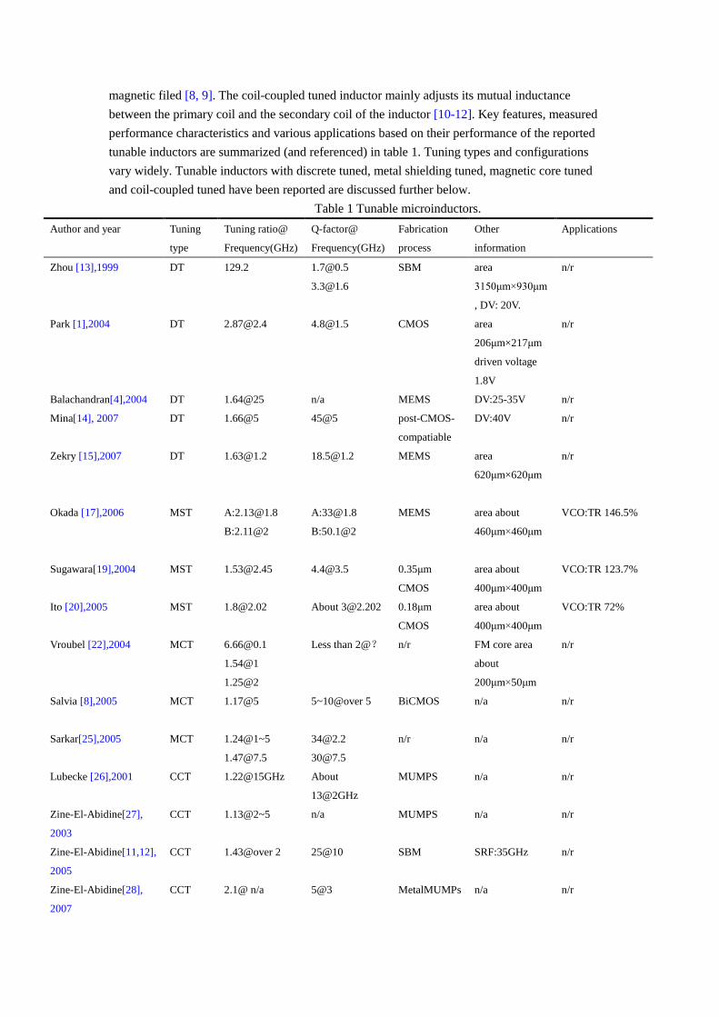
between the two layers or two coils/loop of micoinductors. Fig.9 is the equivalent circuit model of
Page 8
the coupled tuned inductors, where M is the mutual inductance between the two windings or
coils/loop, k is the coupling coefficient, Ls1 and Ls2 are the series inductances of the two coils,
respectively.
21 ss LLkM (3)
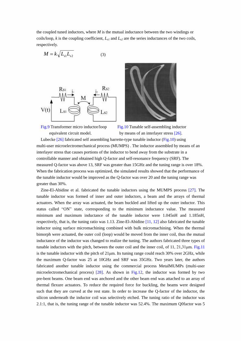
Fig.9 Transformer micro inductor/loop Fig.10 Tunable self-assembling inductor
equivalent circuit model. by means of an interlayer stress [26].
Lubecke [26] fabricated self assembling barrette-type tunable inductor (Fig.10) using
multi-user microelectromechanical process (MUMPS) . The inductor assembled by means of an
interlayer stress that causes portions of the inductor to bend away from the substrate in a
controllable manner and obtained high Q-factor and self-resonance frequency (SRF). The
measured Q-factor was above 13, SRF was greater than 15GHz and the tuning range is over 18%.
When the fabrication process was optimized, the simulated results showed that the performance of
the tunable inductor would be improved as the Q-factor was over 20 and the tuning range was
greater than 30%.
Zine-El-Abidine et al. fabricated the tunable inductors using the MUMPS process [27]. The
tunable inductor was formed of inner and outer inductors, a beam and the arrays of thermal
actuators. When the array was actuated, the beam buckled and lifted up the outer inductor. This
status called “ON” state, corresponding to the minimum inductance value. The measured
minimum and maximum inductance of the tunable inductor were 1.045nH and 1.185nH,
respectively, that is, the tuning ratio was 1.13. Zine-El-Abidine [11, 12] also fabricated the tunable
inductor using surface micromachining combined with bulk micromachining. When the thermal
bimorph were actuated, the outer coil (loop) would be moved from the inner coil, thus the mutual
inductance of the inductor was changed to realize the tuning. The authors fabricated three types of
tunable inductors with the pitch, between the outer coil and the inner coil, of 11, 21,31μm. Fig.11
is the tunable inductor with the pitch of 21μm. Its tuning range could reach 30% over 2GHz, while
the maximum Q-factor was 25 at 10GHz and SRF was 35GHz. Two years later, the authors
fabricated another tunable inductor using the commercial process MetalMUMPs (multi-user
microelectromechanical process) [28]. As shown in Fig.12, the inductor was formed by two
pre-bent beams. One beam end was anchored and the other beam end was attached to an array of
thermal flexure actuators. To reduce the required force for buckling, the beams were designed
such that they are curved at the rest state. In order to increase the Q-factor of the inductor, the
silicon underneath the inductor coil was selectively etched. The tuning ratio of the inductor was
2.1:1, that is, the tuning range of the tunable inductor was 52.4%. The maximum Q0factor was 5
Page 9
at about 3GHz.
Fig.11 Tunable inductor using thermal Fig.12 Tunable inductor was formed by two
bimorph .When the thermal bimorph pre-bent beams. One beam end was anchored
were actuated, the outer coil (loop) would and the other beam end was attached to an
be moved from the inner coil [12]. array of thermal flexure actuators [28].
Fukushige [29] fabricated a new type of tunable inductor using MEMS technology. The inductor
was formed of spiral conical coil (see Fig.13). The height of the coil could be changed from zero
to several hundred micrometers. When the height of the coil was changed, the mutual inductance
of the inductor varied. The inductance value could be a few nano Henries. The inductor coil was
adopted a new MEMS material, Pd-based thin film metallic glass (TFMG) [30, 31]. The measured
and simulated results showed that the tunable inductor could be worked from 50MHz to 16GHz.
At 2 GHz, the inductance values varied from 3.64nH to 3.75nH which means that the tuning range
of the inductor is 3%. However, because the thin film metallic glass was used, the Q-factor of the
tunable inductor was less than two. The authors thought the low Q-factor dued to the high
resistivity of the TFMG (62μΩcm). Chang [32] fabricated the RF MEMS tunable inductor (see
Fig.14) using the bimorph effect of an amorphous silicon and aluminum structural layer. When
there was no applied voltage, the vertical height of the inductor was 450μm, the maximum
Q-factor was 15 at 3.5GHz and SRF was 7GHz. While 2V was applied to the inductor, the
inductance values varied from 5.6nH to 8.2nH which means the tuning range of the inductor was
31.7%.
Fig.13 The unable inductor, formed of spiral Fig.14 The fabricated inductor viewed at 75º tilt.
conical coil, could be changed from zero to The height of the outer turns can reach the
several hundred micrometers. In this photo , emaximum value of 450μm [32].
the height of the coil is 200μm [29].
Page 10
Dell et al. [33] used silicon bulk micromachining technology to fabricate tunable spiral
inductors with the application of low DC bias voltages. With the bias voltages, the movement of
the spiral changed the geometrical structure of the inductor, resulting in a change of the inductance
value. However, if the spiral structure with suspended state was wanted, the intrinsic stress in the
spiral material should be tensile. Silicon nitride via PECVD (plasma enhanced chemical vapor
deposition) to form the spiral support material. The measured inductance values varied from 30 to
100nH at 1MHz. It was found that the inductance decreased as the bias voltage increased. The
inductance values of the tunable inductor at high frequencies were not mentioned in their work.
Hsu et al. presented a double layer spiral coils and studied their coupling effect [34]. Compared to
the initial inductance, the mutual inductance between the double coils decreased 33.5%.
6. Applications
Tunable inductors are widely used in wireless communication systems, such as
voltage-controlled oscillators (VCOs) [16, 20, 35-38], tunable filters [39, 40], tunable low-noise
amplifier (LNA) [3, 41], phase shifters [42], RF front-end [43], wireless sensor[44], especially
when a wide frequency tuning is desired. Tunable inductors would further benefit wireless
communication circuits where impedance matching and frequency tuning would increase the
flexibility and reliability of the system.
Sugawara [16] presented a tunable inductor using redistributed layers. A metal plate was used to
shield the magnetic flux of the inductor. The metal plate was moved by a MEMS actuator. The
inductance varied from 4.80nH to 2.27nH, that is, the tuning ratio was about 2.11. The maximum
value of Q-factor was 50.1at 2GHz.When the tunable inductor was applied to a VCO, the
oscillation frequency range of the VCO achieved 146.5%.YANG [38] presented tunable
inductance LC-tank VCOs implemented in 0.18μm CMOS technology. Two prototype LC-VCOs
utilized the tunable inductors to extend the operating frequencies at 2.85~3.12 GHz and 6.59~7.02
GHz, respectively. The 3GHz VCO using a symmetry transformer provided the tuning range of
2.85 to 3.12 GHz at 1V supply. The power consumption was 4.8mW while the measured phase
noise was -126 dBc/Hz at 1MHz. A small-area stacked transformer was employed in the 7GHz
VCO, which achieved a tuning range of 6.59 to 7.02 GHz and measured phase noise of -114
dBc/Hz at 1MHz , consuming 9mW from a 1.2V supply.
Worapishet [39] proposed an LC bandpass filter using an improved magnetically-coupled
tunable inductor, which was formed of two mutual coils. The best evaluated inductance of the
tunable inductor was 8nH with the mutual coupling coefficient, k=0.6. The simulated response at
the maximum Q value of ten of the LC bandpass filter could varied from 0.7GHz to 1.2GHz, more
than 50% frequency tuning. Moreover, the supplied voltage for the filter was 2V and the
consumption of the filter was less than 9mW of power. Georgescu [40] fabricated the tunable
coupled inductor using 0.18μm CMOS process with a low-resistivity expitaxial substrate. The
tunable inductor was used to form the LC tank in the design of a filter.When the inductance value
was 2nH, the simulated insertion loss in the passband was nearly 0dB.The noise figure and the
input third-order intercepting point (IIP3) were 23dB and -15dBm, respectively.
Lin et al. [3] used the variable planar spiral inductors with MOSFET switch to optimize the
CMOS wideband low-noise amplifiers (LNAs) and to implement low-phase noise VCOs. When
the maximum inductance of the variable inductor was 0.58 nH, a improvement of 74.2% (from 3.1
GHz to 5.4 GHz) in bandwidth of the CMOS wideband LNA were achieved. The measured noise
Page 11
figures were2.2 dB at 1 GHz and 4.0 dB at 6 GHz. The measured input third-order intercepting
point (IIP3) was -3 dBm at 3 GHz. Sugawara [41] proposed a novel wide-tunable LNA using
on-chip tunable inductor with 0.18μm CMOS process. The tunable iuductor was realized using
metal to shield the spiral inductor. The minimum and maximum inductance values were 1.5 and
2.1nH, i.e., tuning ratio of 1.4. At the frequency of 1.9 GHz, the power gain (PG) of the LAN was
13.5 dB, the noise figure (NF) was 7.1 dB, and the IIP3 was -1.9 dBm. The LNA achieved PG of
14 dB and over 10 dB from 1.7 GHz to 3.2 GHz. The NF was not degraded by the shielding metal
plate. This tunable LNA is quite useful for multi-band RF communication system.
Fig.15 Photo of the tunable filter Fig.16 Photo of the LNA
with size of 650μm×650μm [40]. with size of 0.97mm×1.28mm [41].
Tassetti et al. designed and fabricated the tunable inductors [42]. They used two different
wafers, SOI wafer and glass wafer. SOI wafer was for mechanical parts while the glass wafer was
to build the microinductor, pads and electrodes. The inductance values were changed by
controlling magnetic coupling coefficient between the two different coils. The primary coil was
stationary and the secondary coil was patterned on a movable cantilever, which will bend when
there was electrostatic pressure produced by an electrostatic actuator. An anodic bonding step was
used to align the inductors and the electrodes. Thus, the electrodes were used to provide an
electrostatic actuation to change the gap between the two inductors. A high actuation voltage of
150 V was used. The measured results showed that the first prototypes present 50% inductance
variation and the second prototype variation ratio was expected to reach at least 4 over 1 to 10
GHz. Although the tuning range was close to 50%, the Q-factor was unacceptably low due to
strong interactions with silicon. The authors used the tunable inductors and tunable capacitors to
design and realize some tunable radio frequency basic functions, such as tunable impedance
(Fig.17) and tunable phase shifter (Fig.18). The simulated phase shift was of 25° at 5GHz and 48°
at 8GHz.
Page 12
Fig.17 SEM photo of the tunable impedance Fig.18 SEM photo of the phase shifter
[42]. It was a series association of one tunable based on the simple π high –pass cell [42].
inductor and one basic metal-air-metal (MAM) It was composed of two parallel tunable
tunable capacitor. Either a capacitive behavior inductors and one metal-insulator-metal
or an inductive behavior was depended on (MIM) constant value capacitor.
the applied actuation voltages.
Sridhar et al. [44] developed new micromachined tunable inductors with folded flex-circuit
structures and apply it into a hydrogel-based wireless sensor (Fig.17) for biomedical applications.
The tunable inductor was formed of two parallel spiral coils with 5~10mm size, which were
connected and aligned to each other with air gap. The mutual inductance is positive when the
current flow in the two parallel conductors is in the same direction, while it is negative when the
current flow is in opposite direction. The response to the displacement of the coils of the tunable
inductor was 0.40nH/m. The authors though they should extend their efforts to adopt appropriate
response or other materials to form the simple fold-and-sandwich construction of the tunable
inductor.
7. Conclusions
A review of the tunable inductors, from the perspective of their tuning way (e.g. discrete tuned,
metal shielding tuned, magnetic core tuned and coil-coupled tuned) to their applications for
microwave communication systems (e.g. VCOs, filters, phase shifters) is presented. The intent of
this review paper is to provide perspectives to newcomers in the field, and empower potential
end-users with an overall device picture, current status, and a vision of their ultimate performance
capabilities. The difficulty for the device designers is to increase the tuning ratio of the tunable
inductors and reduce their inherently losses due to ohmic losses in the metal traces and due to
substrate resistance and eddy currents. The more efforts toward increasing the Q-factor at
microwave and millimeterwave frequencies for tunable inductors fabricated by standard silicon
technology should be devoted.
Acknowledgement
This work was supported by Fund of National Key Laboratory of Nano/Micro Fabrication
Technology and National Natural Science Foundation of China (NSFC, No. 60876080).
References
[1] Piljae Park, Cheon Soo Kim, Mun Yang Park, Sung Do Kim, Hyun Kyu Yu , Variable
inductance multilayer inductor with MOSFET switch control, IEEE Electron Device Letters,
2004, 25(3):144-146.
Page 13
[2] K.D. Pham, K. Okada, K. Masu , On-chip variable inductor using MOSFET switches, 2005
European Microwave Conference, 2005, vol.2, 4pp.
[3] Yo-Sheng Lin, Hsiao-Bin Liang, Jia-Lun Chen, Ke-Hou Chen, and Shey-Shi Lu, Variable
inductance planar spiral inductors and CMOS wideband amplifiers with inductive peaking,
Microwave and Optical Technology Letters, 2005, 47(4):305-309.
[4] S. Balachandran, B. Lakshminarayanan, T. Weller, M. Smith , MEMS tunable planar inductors
using DC-contact switches, the 34th European Microwave Conference, 2004, 2:713-716.
[5] S. Zhou, X.-Q. Sun and W. N. Carr, A micro variable inductor chip using MEMS relays, Proc.
IEEE Int. Conf. Solid-State Sens. Act., Chicago, IL, Jun. 1997, pp. 1137-1140.
[6] Z. Shifang, S. Xi-Qing and W. N. Carr, A micro variable inductor chip using MEMS relays,
Proc. Int. Conf. Solid State Sensors and Actuators, 1997,vol. 2, pp. 1137-1140.
[7] CM Tassetti, G Lissorgues, JP Gilles, Tunable RF MEMS microinductors for future
communication systems, Proceedings of the 2003 SBMO/IEEE MTT-S International
Microwave and Optoelectronics Conference, IMOC 2003 , Sept. 2003, pp. 541- 545.
[8] James Salvia, James A. Bain, and C. Patrick Yue, Tunable on-chip inductors up to 5 GHz using
patterned permalloy laminations, IEEE International Electron Devices Meeting, 2005. IEDM
Technical Digest, Dec. 2005, pp. 943- 946.
[9] W.P. Shih, Z Li, D.T. McCormick, N.C. Tien, CY Hui, Tunable solenoid microinductors
utilizing permalloy electro-thermal vibromotors, 2004 17th IEEE International Conference on
Micro Electro Mechanical Systems (IEEE-MEMS 2004), 2004 , pp. 793- 796.
[10]C.-M. Tassetti, G. Lissorgues, and J.-P. Gilles, Reconfigurable RF systems based on tunable
MEMS inductors, Proc. 34th Eur. Microw.Conf., Amsterdam, the Netherlands, Oct. 2004, pp.
1165-1168.
[11]Imed Zine-El-Abidine, M Okoniewski, JG McRory, Tunable radio frequency MEMS
inductors with thermal bimorph actuators, J. Micromech. Microeng, 2005, 15:2063-2068.
[12]Imed Zine-El-Abidine, M Okoniewski, JG McRory, RF MEMs tunable inductor using
bimorph microactuators, 2005 Proceedings of International Conference on MEMS, NANO
and Smart Systems, July 2005, pp. 436- 437.
[13]S. Zhou, X.Q. Sun, W.N. Carr, A monolithic variable inductor network using microrelays with
combined thermal and electrostatic actuation, J. Micromech. Microeng, 1999, 9:45-50.
[14]Rais-Zadeh Mina, Paul A. Kohl, and Ayazi Farrokh, A packaged micromachined switched
tunable inductor, IEEE 20th International Conference on Micro Electro Mechanical Systems
(IEEE-MEMS 2007), Jan. 2007, pp. 799-802.
[15]J.E. Zekry, G.N. Daoud, H.A. Ghali, H.F. Ragai, Design and simulation of digitally tunable
high-Q on-chip inductor, 2007 Internatonal Conference on microelectronics, ICM2007,Dec.
2007, pp. 239-242.
[16]H. Sugawara, H. Ito, K. Okada, K. Itoi, M. Sato, H. Abe, T. Ito, K. Masu, High-Q variable
inductor using redistributed layers for Si RF circuits, 2004 Topical Meeting on Silicon
Monolithic Integrated Circuits in RF Systems, Digest of Papers, Sept. 2004,pp.187-190.
[17]Kenichi Okada, Hirotaka Sugawara, Hiroyuki Ito, Kazuhisa Itoi, Masakazu Sato, Hiroshi Abe,
Tatsuya Ito, and Kazuya Masu, On-chip high-Q variable inductor using wafer-level chip-scale
package technology, IEEE Transactions on Electron Devices,2006, 53(9):2401-2406.
[18]Tackya Yammouch, Kenichi Okada and Kazuya Masu, Physical modeling of MEMS variable
inductor, IEEE Transactions on circuits and systems-II: Express Briefs, 2008, 55(5):419-422.
Page 14
[19]H. Sugawara, Y. Yoshihara, H. Ito, K. Okada, and K. Masu, Wide-range RF variable inductor
on Si CMOS chip with MEMS actuator, the 34th European Microwave Conference,
Oct.,2004, pp.701-704.
[20]Y. Ito, Y. Yoshihara, H. Sugawara, K. Okada, and K. Masu, A 1.3-2.8 GHz wide range
CMOS LC-VCO using variable inductor, Proc. IEEE Asian Solid-State Circuits Conf.,
Hsinchu, Taiwan, Nov. 2005, pp. 265-268.
[21]N. Ning, X. P. Li, J. Fan, W. C. Ng, Y. P. Xu, X. Qian, and H. L. Seet, A tunable magnetic
inductor, IEEE Transactions on Magnetics,2006,42(5):1585-1590.
[22]M. Vroubel, Y. Zhuang, B. Rejaei, J.N. Burghartz, Integrated tunable magnetic RF inductor,
IEEE Electron Device Letters,2004,25(12): 787-789.
[23]M. Munakata, M. Namikawa,M. Motoyama, M. Yagi, Y. Shimagda, M. Yamaguchi, and K.-I.
Arai, Magnetic properties and frequency characteristics of (CoFeB)-(SiO1.9) and CoFeB films
for RF application, Proc. Trans. Magn. Soc., Dec. 2002, vol. 2, pp. 388-393.
[24]W.P. Jayasekara, J.A. Bain and M.H. Kryder, High frequency initial permeability of NiFe and
FeAlN, IEEE Transactions on Magnetics,1998, 34(4):1438-1440.
[25]N. Sarkar, D. Yan, E. Horne, H. Lu, M. Ellis, J. B. Lee, R. Mansour, A. Nallani, and G.
Skidmore, Microassembled tunable MEMS inductor, Proc. 18th IEEE Int. Conf. Micro Electro
Mechanical Systems, 2005, pp. 183-186.
[26]V.M. Lubecke, B. Barber, E. Chan, D. Lopez, M.E. Gross, P. Gammel, Self-assembling
MEMS variable and fixed RF inductors, IEEE Transactions on Microwave Theory and
Techniques, 2001, 49(11): 2093-2098.
[27] I. Zine-El-Abidine, M. Okoniewski, and J. G. McRory, A new class of tunable RF MEMS
inductors, Proc. Int. Conf. MEMS, Nano, and Smart Systems, 2003, pp. 114-115.
[28]Imed Zine-El-Abidine and Michal Okoniewski, A tunable radio frequency MEMS inductor
using MetalMUMPs, J. Micromech. Microeng, 2007, 17:2280-2287.
[29]T. Fukushige, Y. Yokoyama, S. Hata, K. Masu, A. Shimokohbe, Fabrication and evaluation of
an on-chip micro-variable inductor, Microelectronic Engineering, 2003, 67-68:582.587.
[30]S. Hata, K. Sato, A. Shimokohbe, Fabrication of thin film metallic glass and its application to
microactuators , Proc. SPIE, 1999, 3892:97-108.
[31]Y. Liu, S. Hata, K. Wada, A. Shimokohbe, Thermal, mechanical and electrical properties
of Pd-based thin film metallic glass, Jpn. J. Appl. Phys., 2001,40:5382-5388.
[32]S. Chang, S. Sivoththaman, A tunable RF MEMS inductor on silicon incorporating an
amorphous silicon bimorph in a low-temperature process, IEEE Electron Device Letters, 2006,
27(11): 905-907.
[33]J.M. Dell,K. Winchester, C.A. Musca, J. Antoszewski, L. Faraone, Variable MEMS-based
inductors fabricated from PECVD silicon nitride,2002 Conference on Optoelectronic and
Microelectronic Materials and Devices, Dec. 2002,pp. 567- 570.
[34]H.M. Hsu, J.Z. Chang, H.C. Chien, Coupling effect of on-Chip inductor with variable metal
width, IEEE Microwave and Wireless Components Letters,2007,17(7):498-500.
[35]M. D. Jensen and L. C. Howlett, Wide frequency range sine wave VCO with a tunable
inductor and capacitor, IEEE Trans. Instrum. Meas., 1989, 38(4): 876-881,.
[36]A. Kral, F. Behbahani, and A. A. Abidi, RF-CMOS oscillators with switched tuning,
Proceedings of the IEEE 1998 Custom Integrated Circuits Conf., May 1998, pp. 555-558.
[37] R. Mukhopadhyay, Y. Park, P. Sen, N. Srirattana, J. S. Lee, S. Nuttinck, A. J. Joseph,
Page 15
J. D. Cressler, and J. Laskar, Reconfigurable RFIC‟s for frequency-agile VCO‟s in Si-based
technology for multi-standard applications, Proc. IEEE MTT-S, 2004, vol. 3, pp. 1489-1492.
[38]Ching-Yuan YANG and Meng-Ting TSAI, High-frequency low-noise voltage-controlled
LC-tank oscillators using a tunable inductor technique, IEICE Trans. Electron., 2006,
vol.E89-C, No.11, pp.1567-1574.
[39]A Worapishet,S Ninyawee, M Chongcheawchamnan, Enhanced tunable coupled inductor for
ultra-wide variable centre frequency LC filters , 2002 Asia-Pacific Conference on Circuits
and Systems(APCCAS '2002),2002,1: 355- 358.
[40]Bogdan Georgescu, Holly Pekau, James Haslett, and John McRory, Tunable coupled inductor
Q-enhancement for parallel resonant LC tanks, IEEE Transactions on Circuits and Systems-II:
Analog and Digital Signal Processing , 2003, 50(10):705-713.
[41]H. Sugawara, Y. Yoshihara, K. Okada, and K. Masu, Reconfigurable CMOS LNA for
software defined radio using variable inductor, Proc. IEEE MTT-S Eur. Microw. Conf., Paris,
France, Oct. 2005, pp.1947-1950.
[42]Charles-Marie Tassetti, Ga elle Lissorgues and Jean-Paul Gilles, New tunable RF MEMS
microinductors design , J. Micromech. Microeng.,2004,14 :S17-S22.
[43]R. Mukhopadhyay, P. Yunseo, P. Sen, N. Srirattana, L. Jongsoo, L.Chang-Ho, S. Nuttinck, A.
Joseph, J. D. Cressler, and J. Laskar, Reconfigurable RFIC‟s in Si-based technologies for a
compact intelligent RF front-end, IEEE Trans. Microw. Theory Tech., 2005,53(1):81-93,
[44]V. Sridhar and K. Takahata, A hydrogel-based wireless sensor using micromachined variable
inductors with folded flex-circuit structures for biomedical applications, IEEE 21st
International Conference on Micro Electro Mechanical Systems(IEEE-MEMS 2008), 2008,
pp.70-73.