A Sample Configuration of AutoQoS for VoIP on Cisco Routers and Catalyst Switches to Support Avaya™ Communication Manager and Avaya™ IP Telephones in a Multi-VLAN Environment - Issue 1.0
Abstract
These Application Notes describe the procedures to configure the VoIP AutoQoS feature on Cisco routers and Catalyst switches to provide QoS service for Avaya Media Servers and Avaya IP Telephones using a Cisco network infrastructure.
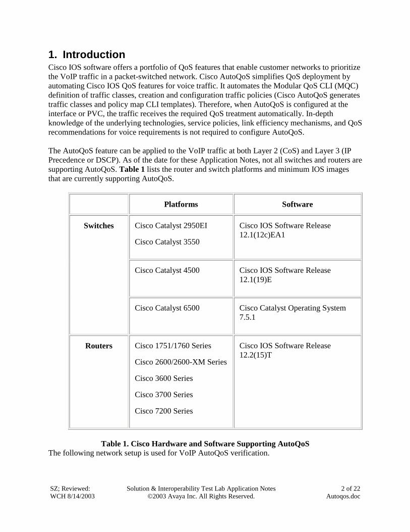
1. Introduction Cisco IOS software offers a portfolio of QoS features that enable customer networks to prioritize the VoIP traffic in a packet-switched network. Cisco AutoQoS simplifies QoS deployment by automating Cisco IOS QoS features for voice traffic. It automates the Modular QoS CLI (MQC) definition of traffic classes, creation and configuration traffic policies (Cisco AutoQoS generates traffic classes and policy map CLI templates). Therefore, when AutoQoS is configured at the interface or PVC, the traffic receives the required QoS treatment automatically. In-depth knowledge of the underlying technologies, service policies, link efficiency mechanisms, and QoS recommendations for voice requirements is not required to configure AutoQoS. The AutoQoS feature can be applied to the VoIP traffic at both Layer 2 (CoS) and Layer 3 (IP Precedence or DSCP). As of the date for these Application Notes, not all switches and routers are supporting AutoQoS. Table 1 lists the router and switch platforms and minimum IOS images that are currently supporting AutoQoS.
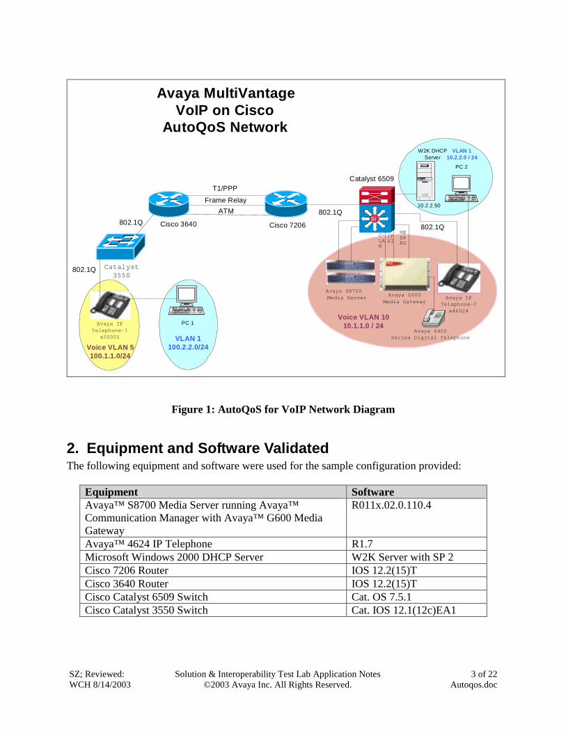
3. Configure the Cisco 7206 and 3640 Routers The AutoQoS feature is not available for Ethernet interfaces (Fast Ethernet and Gigabit) on routers. Compared to the bandwidth offered by these Ethernet interfaces, the WAN interfaces offer much less bandwidth and can become a bottleneck on the router. To cover the most common wide area network (WAN) infrastructures used by enterprise customers, these Application Notes will address the AutoQoS feature configurations for VoIP based on the following three WAN topologies: T1 PPP, Frame Relay and ATM for both high and low speed links. Based on Cisco recommendations, note that the interface or PVC is classified as a low-speed link if its bandwidth is less than or equal to 768 kpbs. In this configuration, the Avaya™ S8700 Media Server and the Avaya IP Telephones are configured to mark the VoIP packets with proper CoS and DSCP values, and the Cisco switches and routers will be responsible for scheduling the traffic based on their CoS/DSCP values. Prerequisites for AutoQos – VoIP
• Enable Cisco Express Forwarding feature using command ip cef. This is a global command and only needs to be entered once.
• Ensure that no QoS policies (service policies) are attached to the interface. This feature cannot be configured if a QoS policy (service policy) is attached to the interface.
• To include Simple Network Management Protocol (SNMP) traps (monitored events), the SNMP server must be enabled.
Currently, there are some restrictions on implementing AutoQoS for VoIP on router WAN interfaces. For implementation considerations, caveats and restrictions, please refer to Appendix A for details. There are two key commands required to make the AutoQoS feature work correctly on the router WAN interfaces. These commands are:
• Bandwidth kb – This command defines the bandwidth that will be used on the serial interface of the router. The AutoQoS feature will use this information to determine how to configure the other QoS related parameters, such as fragmentation and RTP compression. There are different commands to define the bandwidth for PVCs on ATM interfaces. For example, at the ATM interface level, the command PVC 1/50 will create a PVC with a vpi/vci value of 1/50. At this PVC level, the command vbr-nrt 512 will define a 512 KB bandwidth for variable bit rate non-real-time traffic on this PVC. Refer to the related ATM configuration documentation for details.
• Auto qos voip trust – This command enables the AutoQoS feature on the router
interface. The keyword trust is necessary because it instructs the router to perform the QoS functions based the incoming packet’s DSCP or IP Precedence value.
To make sure that the AutoQoS feature works correctly, configure it in this order: Enter the bandwidth command first and then the auto qos voip trust command. Warning: Do not change the interface’s bandwidth after the AutoQoS feature is enabled on that interface, since the AutoQoS feature can not dynamically adjust the configurations based on the new bandwidth settings. If the interface bandwidth must be changed, do the following:
• Use the no auto qos voip trust command to disable the AutoQoS feature on the interface.
• Use the bandwidth command to change the bandwidth. • Enter auto qos voip trust again to enable it.
After the AutoQoS feature is enabled, the router’s IOS will automatically generate a complete configuration based on the interface type and its bandwidth. The command show run can be used to review the configuration. Refer to Appendix B for complete QoS configurations generated by the AutoQoS feature for WAN interfaces used in these Application Notes. Since the AutoQoS feature configurations are identical for both the Cisco 7206 and 3640 routers, only the configuration for the Cisco 7206 router is presented here. Router7206(config)# ip cef --- globally enable Cisco express forwarding Create 802.1Q sub-interfaces for Vlans Router7206(config)# Interface fa0/1.1 --- create a sub-interface fa0/1.1 Router7206(config-if)# Encapsulation dot1q 1 native --- set 802.1Q encapsulation with a native VLAN 1 Router7206(config-if)# Ip address 10.2.2.1 255.255.255.0 Router7206(config)# Interface fa0/1.10 --- create a sub-interface fa0/1.10 Router7206(config-if)# Encapsulation dot1q 10 --- set 802.1Q encapsulation with VLAN 10 Router7206(config-if)# Ip address 10.1.1.1 255.255.255.0 AutoQoS Configuration – Full T1 PPP Router7206(config)# interface s0/0 Router7206(config-if)# bandwidth 1540 --- define the interface speed 1540 kb Router7206(config-if)# auto qos voip trust --- enable AutoQoS on this interface Router7206(config-if)# exit AutoQoS Configuration – Fractional T1 (512kbs) PPP Router7206(config)# interface s0/0 Router7206(config-if)# bandwidth 512 --- define the interface speed 512 kb Router7206(config-if)# auto qos voip trust
Router7206(config-if)# exit AutoQoS Configuration – High-Speed Frame Relay Interface (1.54 mb PVC) Router7206(config)# interface Serial5/0.1 point-to-point --- define a point-to-point interface Router7206(config-if)# bandwidth 1540 --- define the interface speed 1540 kb Router7206(config-if)# frame-relay interface-dlci 200 --- assigns a DLCI 200 to this frame relay interface Router7206(config-fr-dlci)# auto qos voip trust --- enable AutoQoS on this PVC Router7206(config-if)# exit AutoQoS Configuration – Low-Speed Frame Relay Interface (512kbs PVC) Router7206(config)# interface Serial5/0.1 point-to-point Router7206(config-if)# bandwidth 512 --- define the interface speed 512 kb Router7206(config-if)# frame-relay interface-dlci 200 Router7206(config-fr-dlci)# auto qos voip trust Router7206(config-if)# exit AutoQoS Configuration – High-Speed ATM Interface (1.54mb PVC) Router7206(config)# interface atm4/0.1 point-to-point --- create a point-to-point ATM sub- interface Router7206(config-if)# pvc 1/50 --- create a ATM PVC with vpi/vci as 1/50 on this ATM interface Router7206(config-if)# vbr-nrt 1540 1540 --- configure the variable bit rate- nonreal time QoS and specifies the output peak cell rate and output sustainable cell rate Router7206(config-if)# auto qos voip trust --- enable the AutoQoS feature on this PVC Router7206(config-if)# exit AutoQoS Configuration – Low-Speed ATM Interface (512kb PVC) Router7206(config)# interface atm2/0.1 point-to-point Router7206(config-if)# pvc 1/50 Router7206(config-if)# vbr-nrt 512 512 --- configure the variable bit rate non-realtime QoS
and specify the output peak cell rate and output sustainable cell rate as 512k
Router7206(config-if)# auto qos voip trust --- enable the AutoQoS feature on this PVC Router7206(config-if)# exit Note: The AutoQoS feature is enabled at the serial interface for PPP or HDLC, but is enabled at the PVC for the Frame Relay and ATM interfaces.
4. Configure the Cisco Catalyst 6509 and 3550 Switches
4.1. Configure the Cisco Catalyst 6509 Switch The Catalyst 6509 switch with a Layer 3 Super Engine installed can prioritize theVoIP traffic based on the incoming packet’s CoS or DSCP value. In these Application Notes, this switch is configured to use only the CoS value to prioritize the VoIP traffic. There are two basic steps to configure the AutoQoS feature on this switch.
• Use command set qos autoqos to enable AutoQoS globally. • Use command set port qos mod/port autoqos trust cos to enable AutoQoS on an
individual switch port. The trust key word will force the switch to trust the CoS value from the incoming packets.
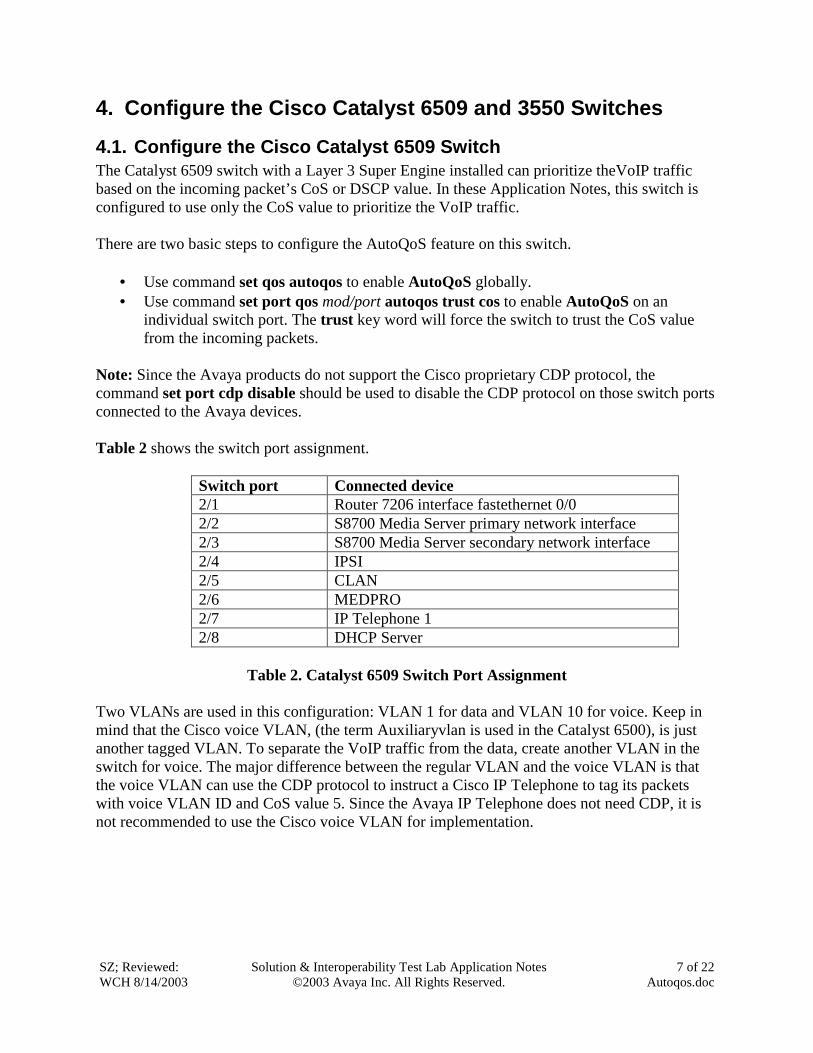
Note: Since the Avaya products do not support the Cisco proprietary CDP protocol, the command set port cdp disable should be used to disable the CDP protocol on those switch ports connected to the Avaya devices. Table 2 shows the switch port assignment.
Switch port Connected device 2/1 Router 7206 interface fastethernet 0/0 2/2 S8700 Media Server primary network interface 2/3 S8700 Media Server secondary network interface 2/4 IPSI 2/5 CLAN 2/6 MEDPRO 2/7 IP Telephone 1 2/8 DHCP Server
Table 2. Catalyst 6509 Switch Port Assignment
Two VLANs are used in this configuration: VLAN 1 for data and VLAN 10 for voice. Keep in mind that the Cisco voice VLAN, (the term Auxiliaryvlan is used in the Catalyst 6500), is just another tagged VLAN. To separate the VoIP traffic from the data, create another VLAN in the switch for voice. The major difference between the regular VLAN and the voice VLAN is that the voice VLAN can use the CDP protocol to instruct a Cisco IP Telephone to tag its packets with voice VLAN ID and CoS value 5. Since the Avaya IP Telephone does not need CDP, it is not recommended to use the Cisco voice VLAN for implementation.
Cat6500(enable)# set spantree portfast 2/1-8 enable -- disable spanning tree on ports 2/1-8 and set all ports into forward status immediately. Cat6500(enable)# set VLAN 1 2/1, 7-8 -- set ports 2/1, 2/7 & 2/8 native VLAN to1 Cat6500(enable)# set VLAN 10 2/2-6 -- create VLAN 10 (for voice) and set ports 2/2-6 native VLAN to 10 Cat6500(enable)# set trunk dot1q 2/1-7 on -- set port 2/1 through 7 in 802.1Q trunking mode Cat6500(enable)# set port trunk dot1q-all-tagged 2/1-48 disable ---- this command makes all packets on native VLAN untagged from port 2/1-48. Untagged native VLAN traffic ---- is necessary for IP Telephones to access DHCP server from VLAN 1. With this version of Cat IOS, the switch ---- tags all packets, including native VLAN, by default. Cat6500(enable)# set port 2/1-8 cdp disable -- disable protocol CDP on port 2/1-8 Cat6500(enable)# set port auxiliaryvlan 2/1-7 10 -- create Auxiliaryvlan 10 and add ports 2/1-7 to this vlan
---------- AutoQoS configuration -----------
Cat6500(enable)# set qos autoqos -- globally enable AutoQoS on switch Cat6500(enable)# set port qos 2/1-7 autoqos trust cos -- enable AutoQoS on port 2/1-7 and set port trust CoS from the incoming packets
Refer to Appendix B for complete configurations generated by the command set port qos autoqos trust cos for this switch.
4.2. Configure the Cisco Catalyst 3550 Switch The Catalyst 3550 switch can prioritize the VoIP traffic based on the incoming packet’s CoS value. The AutoQoS feature is enabled at the interface level, and is not required to be enabled globally as with the Catalyst 6509 switch. There is only one command needed to configure the AutoQoS feature on the switch’s interface.
• Use the command auto qos voip trust to enable the AutoQoS feature on this interface
and trust the CoS value from incoming packets.
Switch3550# config tSwitch3550(config)# VLAN 5 -- create VLAN 5 for voice on the switch. VLAN 1 already exists as default. Interface FastEthernt0/1
Description connect to router 3640Switchport mode trunkSwitchport trunk encapsulation dot1q
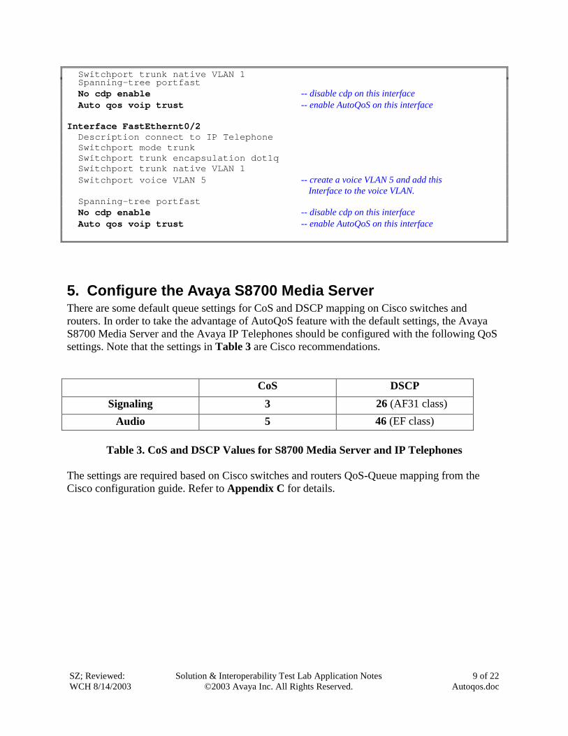
Switchport trunk native VLAN 1Spanning-tree portfastNo cdp enable -- disable cdp on this interface Auto qos voip trust -- enable AutoQoS on this interface
Interface FastEthernt0/2Description connect to IP TelephoneSwitchport mode trunkSwitchport trunk encapsulation dot1qSwitchport trunk native VLAN 1Switchport voice VLAN 5 -- create a voice VLAN 5 and add this
Interface to the voice VLAN.Spanning-tree portfastNo cdp enable -- disable cdp on this interface Auto qos voip trust -- enable AutoQoS on this interface
5. Configure the Avaya S8700 Media Server There are some default queue settings for CoS and DSCP mapping on Cisco switches and routers. In order to take the advantage of AutoQoS feature with the default settings, the Avaya S8700 Media Server and the Avaya IP Telephones should be configured with the following QoS settings. Note that the settings in Table 3 are Cisco recommendations. CoS DSCP
Signaling 3 26 (AF31 class) Audio 5 46 (EF class)
Table 3. CoS and DSCP Values for S8700 Media Server and IP Telephones
The settings are required based on Cisco switches and routers QoS-Queue mapping from the Cisco configuration guide. Refer to Appendix C for details.
Using the change-ip-network-region 1 form to configure the QoS value as follows:
Change ip-network-region 1 Page 1 of 2IP Network Region
Region: 1Name:
Audio Parameters Direct IP-IP Audio Connections? yCodec Set: 1 IP Audio Hairpinning? y
UDP Port Range RTCP Enabled? yMin: 2048 RTCP Monitor Server ParametersMax: 65535 Use Default Server Parameters? y
DiffServ/TOS ParametersCall Control PHB Value: 26VoIP Media PHB Value: 46
Resource Reservation ParametersRSVP Enabled? n
802.1p/Q Enabled? yCall control 802.1p priority: 3
VoIP Media 802.1p priority: 5802.1Q VLAN: 10
Figure 2. Configure CoS and DSCP on the Avaya S8700 Media Server
The QoS values configured in this form will apply to C-LAN and MEDPRO interfaces. The IP Telephones will get these values by using the option 176 for voice VLAN DHCP settings. For the Avaya IP Telephones to boot correctly in this multi-VLAN environment, the two parameters, L2Q=1 and L2QVLAN=10, are required in the option 176 for the native VLAN 1. For detailed DHCP configuration for Avaya IP Telephones, please refer to the Application Notes “Avaya IP Telephony Implementations Guide” from the link at Section 8 Additional References. Use the change ipserver-interface 1 form to assign the QoS values to the IPSI as shown in Figure 3.
change ipserver-interface 1 Page 1 of 1
IP SERVER INTERFACE (IPSI) ADMINISTRATION - PORT NETWORK 1
Keep in mind, with the default CoS and DSCP settings, that call control traffic does not get the same priority as the audio traffic does. The switches and routers use the strict priority queue (Low Latency Queuing) to serve the VoIP bearer traffic, and use the Class-Based Weighted Fair Queuing (CBWFQ) to serve the control traffic with minimum bandwidth guarantees. In reality, depending on network conditions, the VoIP bearer traffic might get through, but the control traffic may get dropped either by switches or routers when congestion occurs. If this is the case, one way to fix this problem is to put the call control traffic into the same queue as the bearer traffic by changing the call control’s CoS and DSCP values to 5 and 46. This is Avaya’s recommendation. Considering the importance of the call control and the little bandwidth it requires, it would be a good practice to implement this without impacting the voice quality. Lab testing has proven it works for this situation. Customers should make the decision as to whether or not to implement this based on their network conditions.
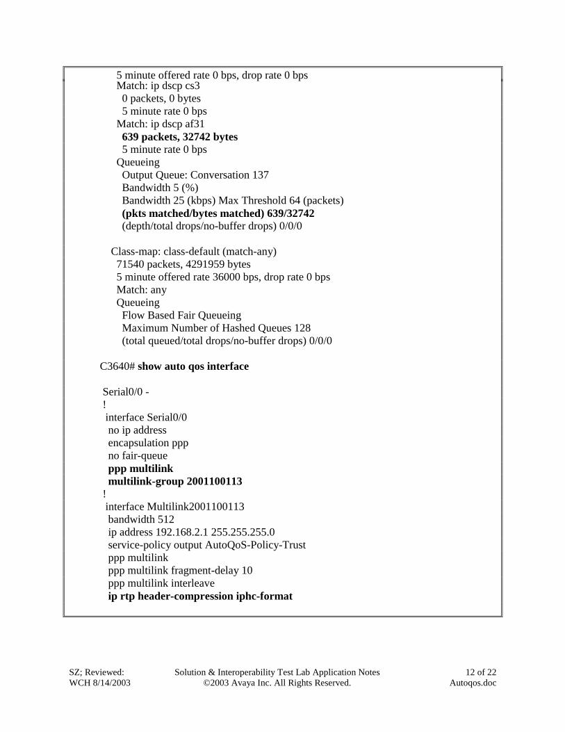
6. Verification Steps The following steps can be used to verify the AutoQoS feature.
• Enable the AutoQoS feature on switches and routers and make phone calls between IP telephone 1 and 2. Verify that the call quality is good.
• The following commands also show the AutoQoS feature status on the switches and routers.
7. Conclusion Avaya Communication Manager and Avaya IP Telephones can take advantage of the AutoQoS feature on Cisco switches and routers to provide customers quality VoIP communications in this environment.
8. Additional References
1. AutoQoS for Voice Over IP (CiscoVoIP White Paper), http://cco-rtp-1.cisco.com/en/US/tech/tk543/tk759/technologies_white_paper09186a00801348bc.shtml
• The AutoQoS — VoIP feature is supported on the following interfaces, data-link connection identifiers (DLCIs), and permanent virtual circuits (PVCs) only:
• Serial interfaces with PPP or High-Level Data Link Control (HDLC) • Frame Relay DLCIs in point-to-point subinterfaces only • ATM PVCs
The AutoQoS — VoIP feature is supported on low-speed ATM PVCs in point-to-point subinterfaces only. The AutoQoS — VoIP feature is supported on high-speed ATM PVCs in any type of subinterface.
Note An ATM PVC is classified as low-speed if its bandwidth is less than or equal to 768 kbps; an ATM PVC is classified as high-speed if its bandwidth is greater than 768 kpbs
• Frame Relay-to-ATM Interworking links
Serial Interface Restrictions
• For a serial interface with a low-speed link, Multilink PPP (MLP) is configured automatically. The serial interface must have an IP address. When MLP is configured, this IP address is removed and put on the MLP bundle. To ensure that the traffic goes through the low-speed link, the following conditions must be met:
o The AutoQoS - VoIP feature must be configured at the both ends of the link. o The amount of bandwidth configured must be the same on both ends of the link.
Frame Relay DLCI Restrictions
• The AutoQoS — VoIP feature cannot be configured on a Frame Relay DLCI if a map class is attached to the DLCI.
• If a Frame Relay DLCI is already assigned to one subinterface, the AutoQoS — VoIP feature cannot be configured from a different subinterface.
• For low-speed Frame Relay DLCIs configured for use on Frame Relay-to-ATM networks, MLP over Frame Relay (MLPoFR) is configured automatically. The subinterface must have an IP address.
∗ Chapter AutoQoS – VoIP from Cisco IOS Release 12.2(15)T
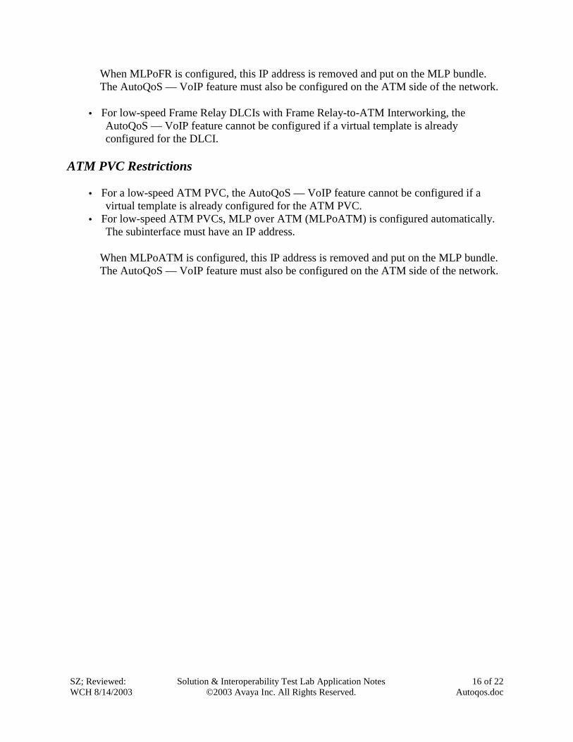
When MLPoFR is configured, this IP address is removed and put on the MLP bundle. The AutoQoS — VoIP feature must also be configured on the ATM side of the network.
• For low-speed Frame Relay DLCIs with Frame Relay-to-ATM Interworking, the AutoQoS — VoIP feature cannot be configured if a virtual template is already configured for the DLCI.
ATM PVC Restrictions
• For a low-speed ATM PVC, the AutoQoS — VoIP feature cannot be configured if a virtual template is already configured for the ATM PVC.
• For low-speed ATM PVCs, MLP over ATM (MLPoATM) is configured automatically. The subinterface must have an IP address.
When MLPoATM is configured, this IP address is removed and put on the MLP bundle. The AutoQoS — VoIP feature must also be configured on the ATM side of the network.
Appendix B -- AutoQoS complete configurations for Catalyst 6500 and 3550 Switches Catalyst 6500
Catalyst 3550
WS-X6348 10/100 switch module 24 10/100 switch port on board
Cat. OS 7.5.1 Cat. IOS 3550 (c3550-I9Q3L2-M) Version 12.1(12c)EA1
-- Configurations generated by AutoQoS -- on the switch port set port qos mod/port policy-source localset port qos mod/port port-basedset port qos mod/port cos 0set port qos mod/port cos-ext 0set port qos mod/port trust-ext untrustedset port qos mod/port trust-device none
If the port type is 1q4t/2q2t, theconfiguration is as follows:
set qos acl ip ACL_IP-TRUSTCOS trust-cosanycommit qos acl ACL_IP-TRUSTCOSset qos acl map ACL_IP-TRUSTCOS mode/portset port qos mod/port trust trust-cos
-- Configurations generated by -- AutoQoS on the switch interfacemls qos trust cosauto qos voip trustwrr-queue bandwidth 20 1 80 0wrr-queue min-reserve 1 5wrr-queue min-reserve 2 6wrr-queue min-reserve 3 7wrr-queue min-reserve 4 8wrr-queue cos-map 1 0 1 2 4wrr-queue cos-map 3 3 6 7wrr-queue cos-map 4 5priority-queue out
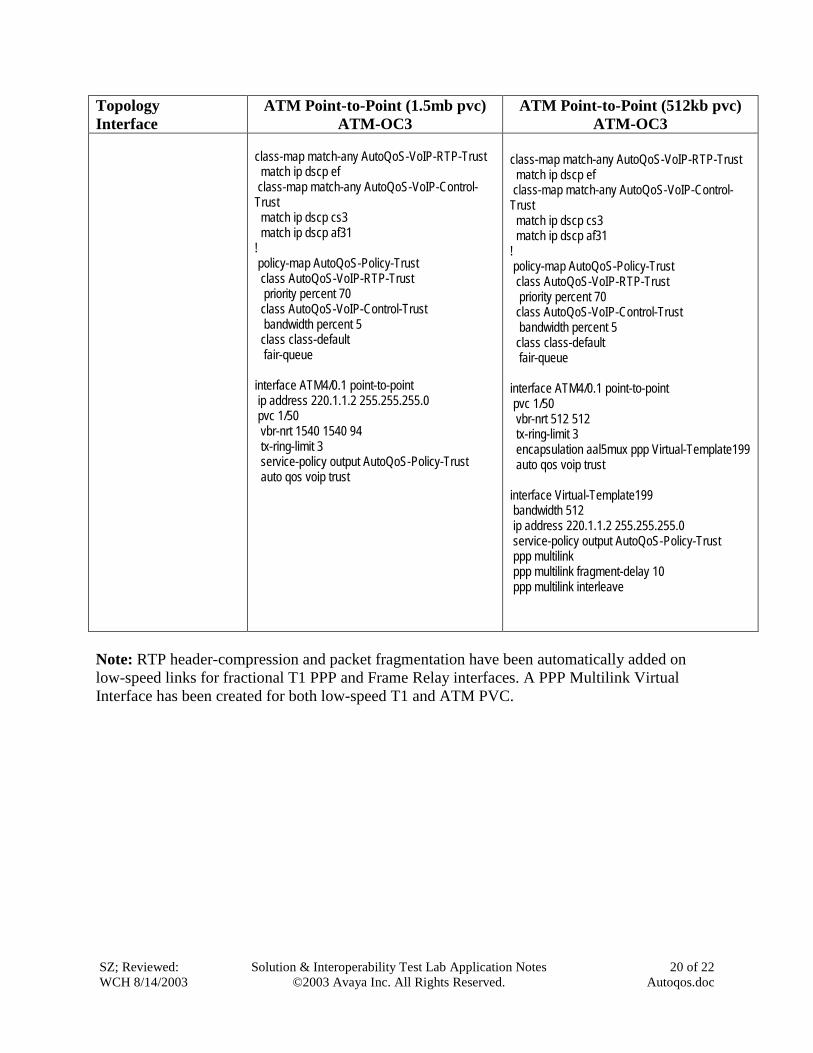
-- AutoQoS complete configurations for the Cisco 7206 and 3640 Routers Since the Cisco 3640 router generates the same configurations as the 7206 router, the table below only outlines the AutoQoS configurations on the Cisco 7206 router with T1 PPP, Frame Relay and ATM PVC for the Avaya IP Telephones and the Avaya Media Server platforms running Avaya Communication Manager.
Topology Point-to-point ppp (1.5 mb) Point-to-point ppp (512 kb) Configurations generated by the Auto qos command
interface Serial0/0 service-policy output AutoQoS-Policy-Trust ! class-map match-any AutoQoS-VoIP-RTP-Trust match ip dscp ef class-map match-any AutoQoS-VoIP-Control-Trust match ip dscp cs3 match ip dscp af31 ! policy-map AutoQoS-Policy-Trust class AutoQoS-VoIP-RTP-Trust priority percent 70 class AutoQoS-VoIP-Control-Trust bandwidth percent 5 class class-default fair-queue
interface Serial0/0 service-policy output AutoQoS-Policy-Trust class-map match-any AutoQoS-VoIP-RTP-Trust match ip dscp ef class-map match-any AutoQoS-VoIP-Control-Trust match ip dscp cs3 match ip dscp af31 ! policy-map AutoQoS-Policy-Trust class AutoQoS-VoIP-RTP-Trust priority percent 70 class AutoQoS-VoIP-Control-Trust bandwidth percent 5 class class-default fair-queue interface Multilink2001100126 bandwidth 512 ip address 192.168.2.3 255.255.255.0 service-policy output AutoQoS-Policy-Trust ip tcp header-compression iphc-format ppp multilink ppp multilink fragment-delay 10 ppp multilink interleave multilink-group 2001100126 ip rtp header-compression iphc-format
class-map match-any AutoQoS-VoIP-RTP-Trust match ip dscp ef class-map match-any AutoQoS-VoIP-Control-Trust match ip dscp cs3 match ip dscp af31 ! policy-map AutoQoS-Policy-Trust class AutoQoS-VoIP-RTP-Trust priority percent 70 class AutoQoS-VoIP-Control-Trust bandwidth percent 5 class class-default fair-queue ! interface Serial5/0.1 point-to-point bandwidth 1540 ip address 210.1.1.2 255.255.255.0 frame-relay interface-dlci 200 class AutoQoS-VoIP-FR-Serial5/0-200 auto qos voip trust map-class frame-relay AutoQoS-VoIP-FR-Serial5/0-200 frame-relay cir 1540000 frame-relay bc 15400 frame-relay be 0 frame-relay mincir 1540000 service-policy output AutoQoS-Policy-Trust
class-map match-any AutoQoS-VoIP-RTP-Trust match ip dscp ef class-map match-any AutoQoS-VoIP-Control-Trust match ip dscp cs3 match ip dscp af31 ! policy-map AutoQoS-Policy-Trust class AutoQoS-VoIP-RTP-Trust priority percent 70 class AutoQoS-VoIP-Control-Trust bandwidth percent 5 class class-default fair-queue interface Serial5/0.1 point-to-point bandwidth 512 ip address 210.1.1.2 255.255.255.0 frame-relay interface-dlci 200 CISCO class AutoQoS-VoIP-FR-Serial5/0-200 auto qos voip trust frame-relay ip rtp header-compression map-class frame-relay AutoQoS-VoIP-FR-Serial5/0-200 frame-relay cir 512000 frame-relay bc 5120 frame-relay be 0 frame-relay mincir 512000 service-policy output AutoQoS-Policy-Trust frame-relay fragment 640
class-map match-any AutoQoS-VoIP-RTP-Trust match ip dscp ef class-map match-any AutoQoS-VoIP-Control-Trust match ip dscp cs3 match ip dscp af31 ! policy-map AutoQoS-Policy-Trust class AutoQoS-VoIP-RTP-Trust priority percent 70 class AutoQoS-VoIP-Control-Trust bandwidth percent 5 class class-default fair-queue interface ATM4/0.1 point-to-point ip address 220.1.1.2 255.255.255.0 pvc 1/50 vbr-nrt 1540 1540 94 tx-ring-limit 3 service-policy output AutoQoS-Policy-Trust auto qos voip trust
class-map match-any AutoQoS-VoIP-RTP-Trust match ip dscp ef class-map match-any AutoQoS-VoIP-Control-Trust match ip dscp cs3 match ip dscp af31 ! policy-map AutoQoS-Policy-Trust class AutoQoS-VoIP-RTP-Trust priority percent 70 class AutoQoS-VoIP-Control-Trust bandwidth percent 5 class class-default fair-queue interface ATM4/0.1 point-to-point pvc 1/50 vbr-nrt 512 512 tx-ring-limit 3 encapsulation aal5mux ppp Virtual-Template199 auto qos voip trust interface Virtual-Template199 bandwidth 512 ip address 220.1.1.2 255.255.255.0 service-policy output AutoQoS-Policy-Trust ppp multilink ppp multilink fragment-delay 10 ppp multilink interleave
Note: RTP header-compression and packet fragmentation have been automatically added on low-speed links for fractional T1 PPP and Frame Relay interfaces. A PPP Multilink Virtual Interface has been created for both low-speed T1 and ATM PVC.
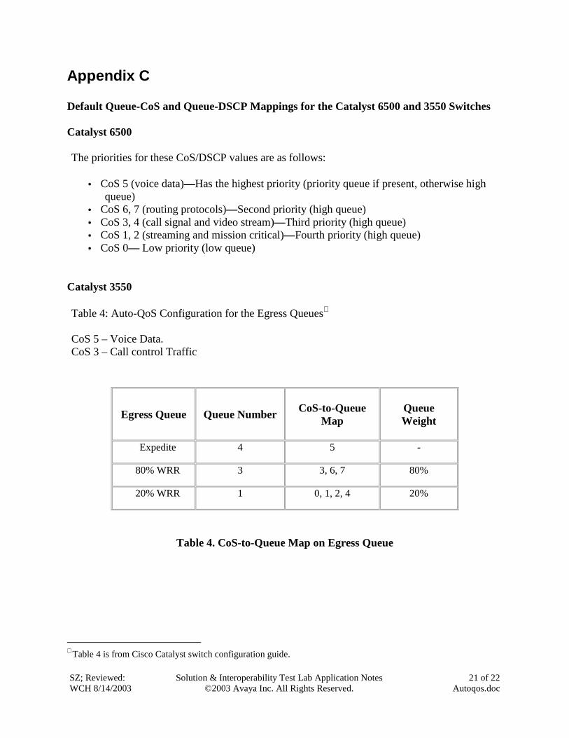
Appendix C Default Queue-CoS and Queue-DSCP Mappings for the Catalyst 6500 and 3550 Switches Catalyst 6500 The priorities for these CoS/DSCP values are as follows:
• CoS 5 (voice data)—Has the highest priority (priority queue if present, otherwise high queue)
• CoS 6, 7 (routing protocols)—Second priority (high queue) • CoS 3, 4 (call signal and video stream)—Third priority (high queue) • CoS 1, 2 (streaming and mission critical)—Fourth priority (high queue) • CoS 0— Low priority (low queue)
Catalyst 3550 Table 4: Auto-QoS Configuration for the Egress Queues∗ CoS 5 – Voice Data. CoS 3 – Call control Traffic
Egress Queue
Queue Number
CoS-to-Queue
Map
Queue Weight
Expedite 4 5 -
80% WRR 3 3, 6, 7 80%
20% WRR 1 0, 1, 2, 4 20%
Table 4. CoS-to-Queue Map on Egress Queue
∗ Table 4 is from Cisco Catalyst switch configuration guide.