48
I
I

I
Acknowledgment:
“Completing this capstone project would not have been possible without the guidance,
inspiration and help I have been awarded during this semester specifically and my whole
curriculum generally.
First and foremost, I aspire to express my deepest gratitude to Mr. Rachid Lghoul for his
infinite and valuable assistance, supervision and motivation. Your involvement and support are
sincerely esteemed and acknowledged. I sincerely thank you for always being available to answer
my questions, clarify my doubts and help me find the right path to follow.
I would also like to address my warmest gratefulness to Dr. Yassine Salih Alj for his time and
dedication and to all the professors I have attended classes with during my undergraduate studies.
Your help might seem implicitly linked to my project, but is definitely valued in its completion.
Last but not least, I am extremely thankful and indebted parents, family and friends for their
constant support, generosity and enthusiasm. I would not have reached where I am standing today
without their ongoing encouragement throughout the years.”
II
Table of Content
ABSTRACT ................................................................................................................................. IV
LIST OF ILLUSTRATIONS & TABLES ................................................................................. V
LIST OF ABREVIATIONS ..................................................................................................... VII
1. INTRODUCTION: ................................................................................................................ 1
1.1. GENERAL CONTEXT .......................................................................................................... 1
1.2. THE MOROCCAN CONTEXT: .............................................................................................. 1
1.3. STEEPLE ANALYSIS: ....................................................................................................... 2
2. LITERATURE REVIEW: .................................................................................................... 4
3. SMART GRID: ...................................................................................................................... 6
4. DEMAND RESPONSE: ........................................................................................................ 8
5. MICROGRID: ..................................................................................................................... 10
5.1. DEFINITION: .................................................................................................................... 10
5.2. MICROGRID OPERATION: ................................................................................................. 11
5.3. COMPONENTS OF A MICROGRID: ..................................................................................... 11
5.3.1. Wind Power ............................................................................................................. 12
5.3.2. Photovoltaic System ................................................................................................ 13
v Definition: ................................................................................................................... 13
v PV cell mathematical model: ...................................................................................... 15
5.3.3. Rectifier : ........................................................... Erreur ! Le signet n’est pas défini.
III
5.3.4. Inverter: .................................................................................................................. 17
5.3.5. Storage .................................................................................................................... 17
v Definition: ................................................................................................................... 17
v Battery mathematical model: ...................................................................................... 19
5.3.6 DC BOOST CONVERTER: .............................................................................................. 21
v Perturb & Observe Method ......................................................................................... 22
5.3.7 BUCK-BOOST CONVERTER: ......................................................................................... 24
5.4. DC MICROGRID: .............................................................................................................. 24
5.5. MICROGRID CONTROLS: .................................................................................................. 25
a) Local Controllers: ....................................................................................................... 26
b) Centralized Controllers: .............................................................................................. 26
c) Decentralized controllers: ........................................................................................... 26
6. A SOLAR PANEL PARKING LOT: ................................................................................ 27
6.1. OVERVIEW: ..................................................................................................................... 27
6.2. MODELING OF THE SUN POSITION: .................................................................................. 29
7. SIMULATION OF THE MICROGRID SYSTEM & RESULTS: ................................. 33
7.1 INTRODUCTION: ............................................................................................................... 33
7.2 SOLAR PANEL: ................................................................................................................ 34
7.3 THE LOAD: ...................................................................................................................... 36
7.4 THE BATTERY: ................................................................................................................ 37
8. CONCLUSION & FUTURE WORK: ............................................................................... 38
9. REFERENCES .................................................................................................................... 39
IV
ABSTRACT
Energy consumption is considered as one of the most, if not the most, trendiest topics as it is
critical to human life. The aim of this capstone project is to design a smart small-scale electric
system called smart microgrid in order to be more efficient in terms of energy usage. The mismatch
between the production and consumption of energy results in the loss of huge amount of energy.
This is why those microgrids are really important since their usage consists of generating energy
from renewable sources such photovoltaic cells according to the demand. The project will focus
on a specific area in our campus. The first thing to do is to forecast the demand of energy in that
area. Following that demand, we will try to manage the production (using a renewable energy
source) and consumption of energy following an energy management system. If there is any
surplus in the energy generation, it will be stored in a specific form and used later. All those steps
will be monitored using a software. When it comes to the design phase, the project will get
information from the microgrid and then process it to not get energy losses. For the results, they
will be confirmed by using National Instrument Technology. Also, many models will be generated
using MATLAB to generate the most accurate simulation. If times allows, a mock-up will be
constructed so as to demonstrate the efficiency of the usage of smart microgrids. For the technical
implication, the microgrid enables to optimize the production of the renewable electricity at a local
scale. It can also delivery an auxiliary service to the public network of distribution by helping
maintain the stability of the tension and lighten it when it gets cut from the distribution network.
When it comes to societal implication, a microgrid provides an answer to the evolution of the
fundamental needs of a region in terms of energy. It particularly offers a secure and more reliable
network if a fire breaks out. Since this project is local, it is going to enable more initiatives to be
taken as well as facilitate the establishment of new partnerships between local actors.
V
LIST OF ILLUSTRATIONS & TABLES Figure 1.1: DNI, GHI, ATaL in Morocco.
Figure 1.2: Solar Radiation in Morocco.
Figure 3.3: Comparison between old grid and smart grid.
Figure 4.4: Simple architecture of a microgrid.
Figure 5.5: Effects of demand side management.
Figure 5.6: Architecture of a microgrid using HOMER.
Figure 5.7: Horizontal and vertical wind turbines and their components.
Figure 5.8: Solar cell, solar panel and PV system.
Figure 5.9: Monocrystalline and polycrystalline solar panel.
Figure 5.10: Circuit of a PV cell.
Figure 5.11: Typical Grid Battery Rack.
Figure 5.12: Circuit of a Battery.
Figure 5.13: Boost Converter Power Stage.
Figure 5.14: Power VS Voltage for P&O Algorithm.
Figure 5.15: P&O Algorithm.
Figure 5.16: Circuit of a DC Microgrid.
Figure 6.17: Power consumption of building 7.
Figure 6.18: Area for Solar Panel Parking.
Figure 6.19: Earth Rotation Orbit around the Sun.
Figure 6.20: The Sun’s Altitude and Azimuth Angles.
Figure 6.21: The Solar Declination Angle.
Figure 6.22: A Day’s Profile of the Sun’s altitude and Azimuth angle.
Figure 7.23: An illustration of the Entire Microgrid System.

VI
Figure 7.24: Simulation of the Solar Panel.
Figure 7.25: Power Generation of the PV System for One Day.
Figure 7.26: Load Profile for One Day.
Figure 7.27: State of Charge of the Battery for one day..
VII
LIST OF ABREVIATIONS
Ø AC: Alternative Current.
Ø BESS: Battery Energy Storage System.
Ø DC: Direct Current.
Ø DER: Distributed Energy Resources.
Ø DR: Demand Response.
Ø ESS: Energy Storage System.
Ø Li-ion: Lithium-ion.
Ø LV: Low Voltage.
Ø MPPT: maximum power point tracking
Ø PV: Photovoltaic.
Ø RE: Renewable Energy.
Ø SOC: State of Charge.
Ø TSO: Transmission System Operator.
1
1. INTRODUCTION:
1.1. General Context
By 2035, the population of the world is supposed to increase by almost 1.5 billion which will
make the population reach 8.8 billion people. This increase in the population will cause two things.
The first one is an increase of the demand on energies. The demand on energies will cause the
decrease of fossil fuels resources and the increase of CO2 emissions to reach approximately 39
billion tones by 2035. The second one is creating issues related to power grids which can be
resumed to:
• Congestion: The components of the power grids are old and cannot satisfy the demand for
a growing population
• Security, protection, transmission losses and losses due to the gap between production and
consumption.
• Problems emerge when the power grids are far from where the power is needed.
1.2. The Moroccan Context: When it comes to the energy sector, Morocco knows a real contrast. It is located in a great
geographical position enabling it to have a great potential in terms of renewable energies, but still
it imports nearly 96% of its energy. For instance, when it comes to the solar energy some
interesting statistics show that Morocco can get great amounts of energy from the Sun.
o The Global Horizontal Irradiance (GHI) reaches a monthly average of 3.91
kWh/m2/day.
o The Direct Normal Irradiance (DNI) reaches a monthly average of 3.71
kWh/m2/day.
2
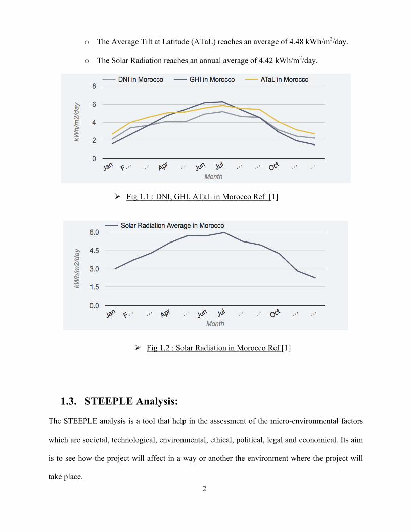
o The Average Tilt at Latitude (ATaL) reaches an average of 4.48 kWh/m2/day.
o The Solar Radiation reaches an annual average of 4.42 kWh/m2/day.
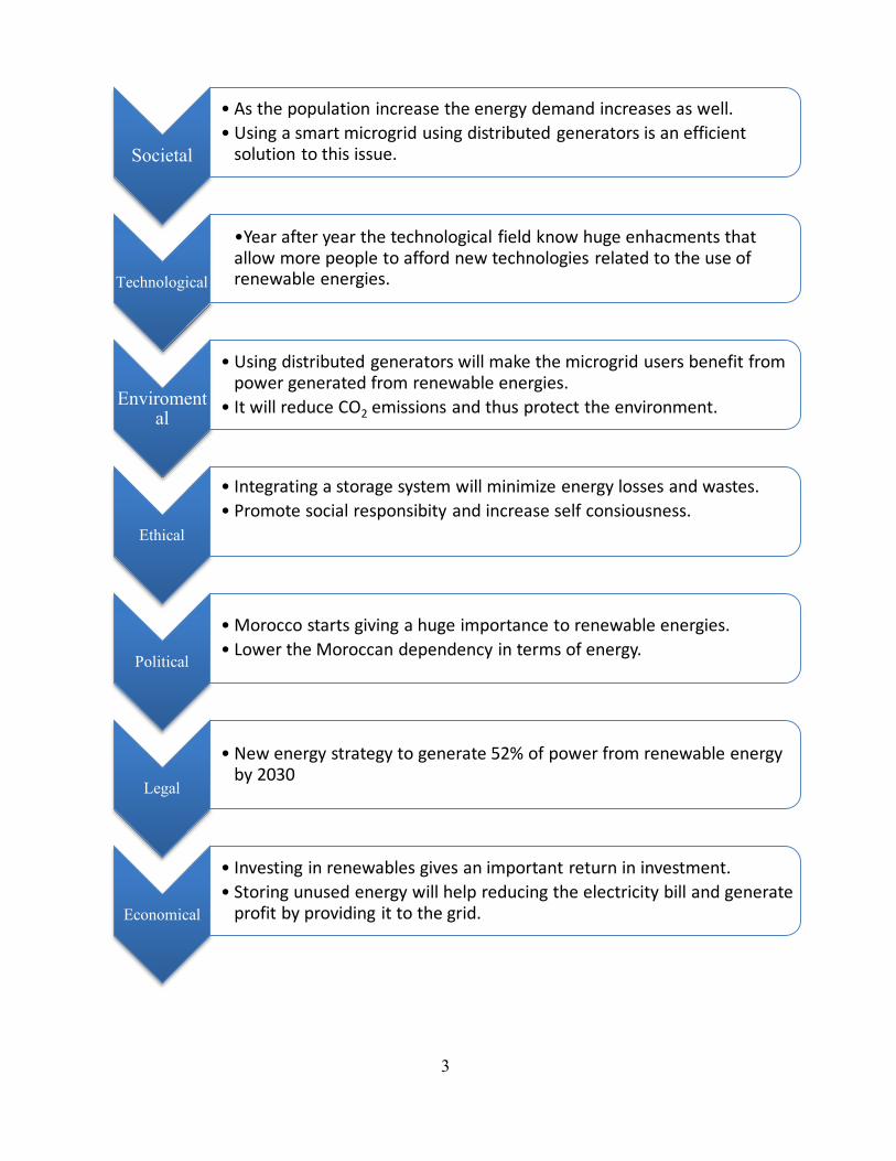
1.3. STEEPLE Analysis: The STEEPLE analysis is a tool that help in the assessment of the micro-environmental factors
which are societal, technological, environmental, ethical, political, legal and economical. Its aim
is to see how the project will affect in a way or another the environment where the project will
take place.
Ø Fig 1.1 : DNI, GHI, ATaL in Morocco Ref [1]
Ø Fig 1.2 : Solar Radiation in Morocco Ref [1]
3
Societal
• Asthepopulationincreasetheenergydemandincreasesaswell.• Usingasmartmicrogridusingdistributedgeneratorsisan efficientsolutiontothisissue.
Technological
•Year afteryearthetechnologicalfieldknowhugeenhacmentsthatallowmorepeopletoaffordnewtechnologiesrelatedtotheuseofrenewableenergies.
Enviromental
• Using distributedgeneratorswillmakethemicrogridusersbenefitfrompowergeneratedfromrenewableenergies.
• It willreduceCO2 emissionsandthusprotecttheenvironment.
Ethical
• Integrating astoragesystemwillminimizeenergylossesandwastes.• Promote socialresponsibityandincreaseselfconsiousness.
Political
• Morocco startsgivingahugeimportancetorenewableenergies.• LowertheMoroccandependencyintermsofenergy.
Legal
• Newenergystrategytogenerate 52%ofpowerfromrenewableenergyby2030
Economical
• Investinginrenewablesgives animportantreturnininvestment.• Storing unusedenergywillhelpreducingtheelectricitybillandgenerateprofitbyprovidingittothegrid.
4
2. Literature Review:
The thesis by Hamad Ahmed introduces the notion of microgrid system as well as the major
mechanisms that compose that microgrid. It thoroughly discusses both the autonomous and grid-
connected modes and provides a definition of the local, centralized and decentralized types of
control. This thesis was published within the Missouri University of Science and Technology that
is known as a research pioneer. Indeed, they have built four inspirational solar villages that allowed
students to enhance the aspects of the system. Consequently, within the thesis, a computer model
was designed and all the different houses and components of the Missouri solar village are
displayed a long with the techniques and technologies used there.
Ngoc An Luu, in his publication about Control and management strategies for a microgrid
first addressed environmental restrictions and the increase in fuel prices and considered them as
an opportunity to better exploit renewable sources of energy in power systems. He states that in
order to integrate the renewable sources in an electrical grid, a microgrid is required. This concept
encompasses a low voltage system with DERs which stands for distributed energy resources as
well as flexible load and storage devices. As the integration of renewable energy resources into a
microgrid may be very challenging and may have impacts on the operation of the microgrid, Ngoc
An Luu’s thesis suggests strategies that promote optimal sizing and security, reliability and
efficiency such as battery energy storage systems (BESS) and photovoltaic productions (PV). A
method is also proposed to manage optimally the energy that goes in microgrid operation.
Lessons from Campus Microgrid Design and Implementation by Hassan Farhangi
introduced the different phases of a microgrid as a complex system going from design to usage
5
through implementation and testing. This book encapsulates the essence of eight years of
experience and research in this specific field. It traces the history of microgrids back to the
discussion phase of the idea. It also provides a clear explanation about the concept of microgrid,
its roes and its architecture. It then moves to introducing the the microgrid initiative, the drivers
behind the development of such technology before moving to the technical part which includes an
extensive presentation about the electrical storage, microgrid’s communication and the main
requirements needed for data processing. It also covers a wide set of experiences and lessons
grasped by the BCIT’s (British Columbia Institute of Technology) design team while researching
the topic and trying to design the system.
Ramon Zamora and Anurag K. Srivastava, in their work, assert that the the drastic increase
in demand for secure, reliable, efficient and sustainable electricity has generated significant
interest in microgrids. Their paper translates their effort to improve that technology and focuses of
controls of microgrid in association with energy storage. An overview of the current control
mechanism is provided along with the challenges it faces or may face.
Modeling and simulation of a residential microgrid supplied with PV/batteries in
connected/disconnected modes—Case of Morocco co-published by Dr. Tazi, Dr. Abbou, Dr.
Bannour and Dr. Abdi reviews the different components of a micro-grid with their respective
mathematical equations. The model introduced was built in Matlab/Simulink and the scenarios
tested in the system validation were described in detailed. This model was built according to the
rules of distribution of a Moroccan grid code. The sample was selected in a way that would allow
a representation of power consumption of an average household in the region of Ifrane. The
6
scenarios previously mentioned were used to test the micro-grid in normal operation as well as in
faulty operation that need disconnection from the utility grid.
In this thesis we will conduct a solar system simulation using MATLAB software and by using
real reliable data of a working system. Moreover; the energy management system along with the
battery controllers are introduced with an analysis of a structure that could Increase the
effectiveness of the system. Furthermore; this thesis will discuss the energy flow and consist an
algorithm that manages this flow taking into consideration the state of charge; power generation,
and load. This late algorithm consists of different steps taking into consideration the following:
charge and discharge of the battery; Import of power from a significant utility, and the export of
power to a certain load.
The following section introduces the smart grids.
3. Smart Grid:
A smart grid refers to a new and innovative system of electrical distribution that has the
ability to manage and control information and power generation. It is capable of using different
power sources to get the energy needed. The smart grid is also capable to store the produced energy
that was not used by the consumer [2]. What makes the smart grid really innovative is the shift
that one can notice between the old grid and the new one. A smart grid relies more on a two-way
communication system between the power supplier and the power consumer. Here the power
supplier will produce energy using different energy sources (solar, wind power) based on the
information got from the power consumer [3]. One can notice the difference compared to the old
grid where a hierarchical system was followed, i.e. the power producers continue to produce
energy even if the demand was met.
7
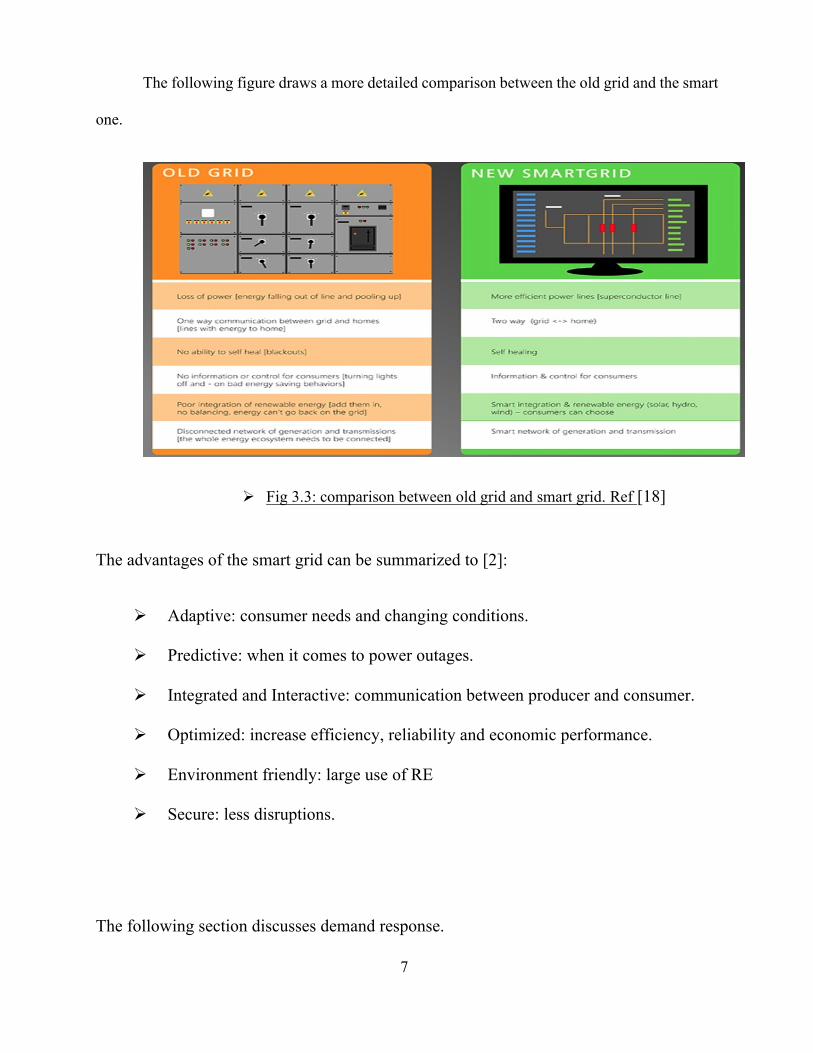
The following figure draws a more detailed comparison between the old grid and the smart
one.
The advantages of the smart grid can be summarized to [2]:
Ø Adaptive: consumer needs and changing conditions.
Ø Predictive: when it comes to power outages.
Ø Integrated and Interactive: communication between producer and consumer.
Ø Optimized: increase efficiency, reliability and economic performance.
Ø Environment friendly: large use of RE
Ø Secure: less disruptions.
The following section discusses demand response.
Ø Fig 3.3: comparison between old grid and smart grid. Ref [18]
8
4. Demand Response:
The Federal Energy Regulatory Commission defines demand response as: “Changes in electric
usage by end-use customers from their normal consumption patterns in response to changes in the
price of electricity over time, or to incentive payments designed to induce lower electricity use at
times of high whole- sale market prices or when system reliability is jeopardized.” [4]
Demand response has many advantages that can be summarized as follows:
• DR reduces the environmental impacts caused by the installation of new power plants because it
lowers system peak load.�
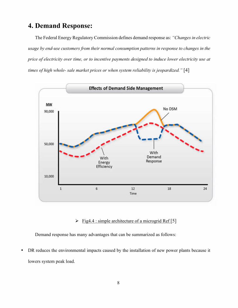
Ø Fig4.4 : simple architecture of a microgrid Ref [5]
9
• DR allows for an increased reliability by the transmission operators when it comes to transmission
network.
This improvement in the reliability of the network can be achieved thanks to a reduction in the
likelihood of forced outages that occurs while system reserves are below the desired levels. DR
transmitted via TSO helps return reserves of the system to pre-contingency levels, through a
reduction in electricity demand during critical times. While a peaking power plant might take
around 30 minutes to more to fully ramp up, a DR can be dispatched in no more than 5 minutes.
At a distribution level, a DR can be used by DSO to manage the network constraints in such a
way that it releases the transfer problem of the voltage constraint power, dismisses more or less he
congestion in the distribution substations and simplifies the outage management and enhances the
supply quality.
DR discharges the different components of the network from the unwanted stress during peak
periods of congestion incidents. This results in a significant improvement in the service quality
and reliability. During incidents, the load limitation is expected to reduce the non-supplied load
universal monetary value.
A flat rate is established so that retailers can sell electricity purchased from the wholesale
market to their consumers. That is why they face in the real-time scope financial risks that emerge
because of the volatility in spot prices. To somewhat mitigate this risk, they can ask their
consumers to try to decrease their consumption when spot rate are the most volatile and reach their
peak; these customers are promised a reward for the reduction in their consumption.
The impacts of DR on a short-term on electricity markets involve financial benefits regarding
the consumers as well as utility. Implementation of new technologies such as distributed
generation (that can be applied to solar, small wind as well as geothermal) and storage (including
stand-alone and PHEV) can be considered as a motivating factor to include DR as a main
10
component of the smart grid. During fast speed wind for example, the generation is fairly in excess.
A restriction on wind generation is thus very inefficient for most wind farms, extending the
payback period significantly. Consequently, DR can be employed during such periods of time to
help increase demand.
The following section will focus on a definition of a microgrid and its advantages, its modes
of operations, and will discuss its major components.
5. Microgrid:
5.1. Definition:
A group of generating resources and loads in an electrically defined area that can operate as a
single unit all by itself by being isolated from the main grid or connected to it and operating with
it in a coordinated manner. When it is isolated from the main grid it is considered as a way to use
local resources to meet the electrical demand of a single costumer, university campus, offices, or
a community while trying to meet economic objectives, reliability objectives and reduce emissions
[6].
Microgrids can generate and distribute power using different energy sources such as wind
turbines, fuel cells, and photovoltaic (PV) systems that are connected to storage devices that help
in the constant supply of the local loads and reduce power outages [7]. Here two types of local
loads are found. The first one is the sensitive load that refers to a load that is constantly supplied.
While the second one is the non-sensitive load which is a load that can be shut down in case
disturbances occur in the main grid.
11
5.2. Microgrid Operation: When it comes to microgrids, they can operate under two modes:
• Grid connected mode: where, as its name indicates, the microgrid is connected to the grid
and can either get energy from it or transfer energy to it. In that case, if any kind of
disruption happens, the microgrid is automatically disconnected from the grid and start
operating under the island mode which is the second mode [7].
• Island mode: in this mode the microgrid works autonomously. Its aim is to meet the local
loads’ needs by generating the needed amount of energy without relying on the utility grid.
The microgrid can shift to this mode if the utility grid knows any kind of disturbance and
then go back to the grid connected mode.
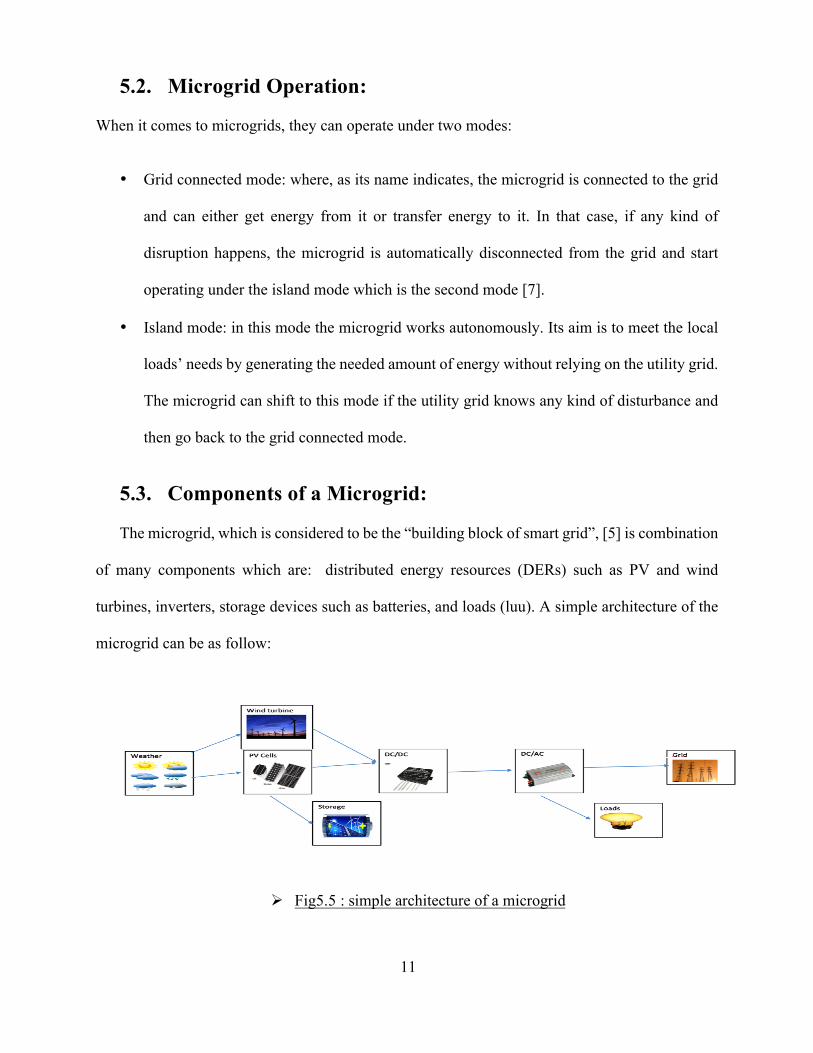
5.3. Components of a Microgrid:
The microgrid, which is considered to be the “building block of smart grid”, [5] is combination
of many components which are: distributed energy resources (DERs) such as PV and wind
turbines, inverters, storage devices such as batteries, and loads (luu). A simple architecture of the
microgrid can be as follow:
Ø Fig5.5 : simple architecture of a microgrid
12
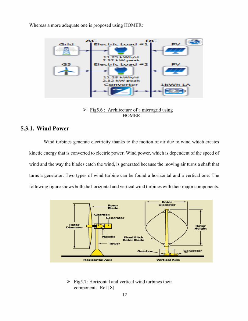
Whereas a more adequate one is proposed using HOMER:
5.3.1. Wind Power
Wind turbines generate electricity thanks to the motion of air due to wind which creates
kinetic energy that is converted to electric power. Wind power, which is dependent of the speed of
wind and the way the blades catch the wind, is generated because the moving air turns a shaft that
turns a generator. Two types of wind turbine can be found a horizontal and a vertical one. The
following figure shows both the horizontal and vertical wind turbines with their major components.
Ø Fig5.6 : Architecture of a microgrid using HOMER
Ø Fig5.7: Horizontal and vertical wind turbines their components. Ref [8]
13
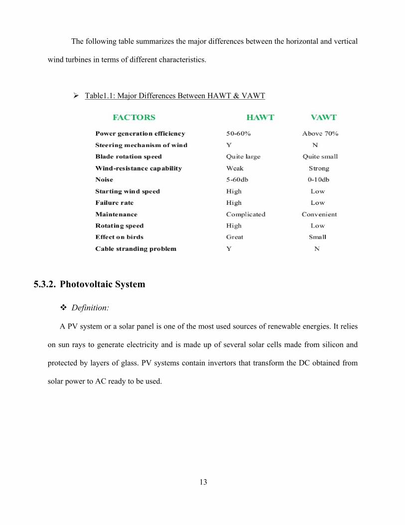
The following table summarizes the major differences between the horizontal and vertical
wind turbines in terms of different characteristics.
5.3.2. Photovoltaic System
v Definition:
A PV system or a solar panel is one of the most used sources of renewable energies. It relies
on sun rays to generate electricity and is made up of several solar cells made from silicon and
protected by layers of glass. PV systems contain invertors that transform the DC obtained from
solar power to AC ready to be used.
Ø Table1.1: Major Differences Between HAWT & VAWT
14
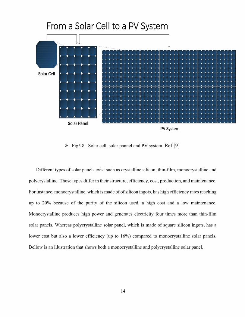
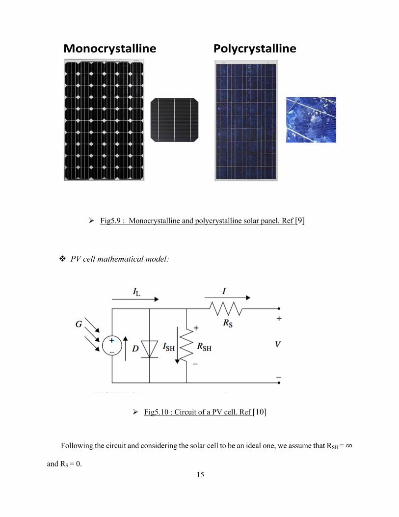
Different types of solar panels exist such as crystalline silicon, thin-film, monocrystalline and
polycrystalline. Those types differ in their structure, efficiency, cost, production, and maintenance.
For instance, monocrystalline, which is made of of silicon ingots, has high efficiency rates reaching
up to 20% because of the purity of the silicon used, a high cost and a low maintenance.
Monocrystalline produces high power and generates electricity four times more than thin-film
solar panels. Whereas polycrystalline solar panel, which is made of square silicon ingots, has a
lower cost but also a lower efficiency (up to 16%) compared to monocrystalline solar panels.
Bellow is an illustration that shows both a monocrystalline and polycrystalline solar panel.
Ø Fig5.8: Solar cell, solar pannel and PV system. Ref [9]
15
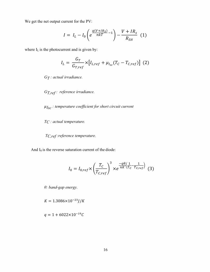
v PV cell mathematical model:
Following the circuit and considering the solar cell to be an ideal one, we assume that RSH =∞
and RS = 0.
Ø Fig5.9 : Monocrystalline and polycrystalline solar panel. Ref [9]
Ø Fig5.10 : Circuit of a PV cell. Ref [10]
16
We get the net output current for the PV:
# = #% − #' () *+,-./01 23 −
4 + #67689
(1)
where IL is the photocurrent and is given by:
#% = =>
=>,@AB× #%,@AB + D,EF(1G − 1G,@AB) (2)
GT : actual irradiance.
GT,ref : reference irradiance.
DIsc : temperature coefficient for short circuit current
TC : actual temperature.
TC,ref :reference temperature.
And I0 is the reverse saturation current of the diode:
#' = #',@AB×1G
1G,@AB
I
×(2)JKL
3>M2 3>M,NOP (3)
θ: band-gap energy.
R = 1.3086×10²WIX/R
Z = 1 + 6022×1023[\
17
5.3.3. Rectifier:
The rectifier is a device used to convert AC to DC. It is used in order to generate voltages
and current waveforms for DC components [12]. Different types of rectifiers exist, among them
we find: the half, full three phase half and three phase full wave rectifier.
5.3.4. Inverter:
The inverter is an electrical device that has the opposite function of the rectifier. It is mainly
used to convert one frequency of AC power to another. This is done either by using a
cycloconverter which function is to convert instantly and directly the AC power frequencies, or by
using a rectifier-inverter which converts first an AC power to a DC one before converting the
resulting DC power into the desired AC power at the desired frequency.
5.3.5. Storage
v Definition:
The use of PV systems and wind turbine to generate energy in a microgrid implies the use
of an energy storage system (ESS). Whether the microgrid is connected to the main grid or is
working on island mode, it is very important to use an ESS. When the microgrid is on island mode,
the demand of the loads of the microgrid needs to be met even if the peak of demand does not
match the peak of renewable energy generation. That is to say that the energy generated using solar
power (its peak is at noon) and the one generated using wind (peak may vary during the day and
night) need to be stored using a convenient and efficient ESS in order to be used when demand
peaks. Without that system and if the peaks do not match, the generated energy will be unexploited
and lost. Now if the microgrid is connected to the main grid the energy storage system is used in
two main cases. The first one is when the price of power is high, in that case the microgrid supplies
18
the main grid with power in order to maximize the profit. The second case is when the microgrid
draws energy from the main grid and the pricing is higher than the usual one. In that case, the
energy stored in the system will be used[11].
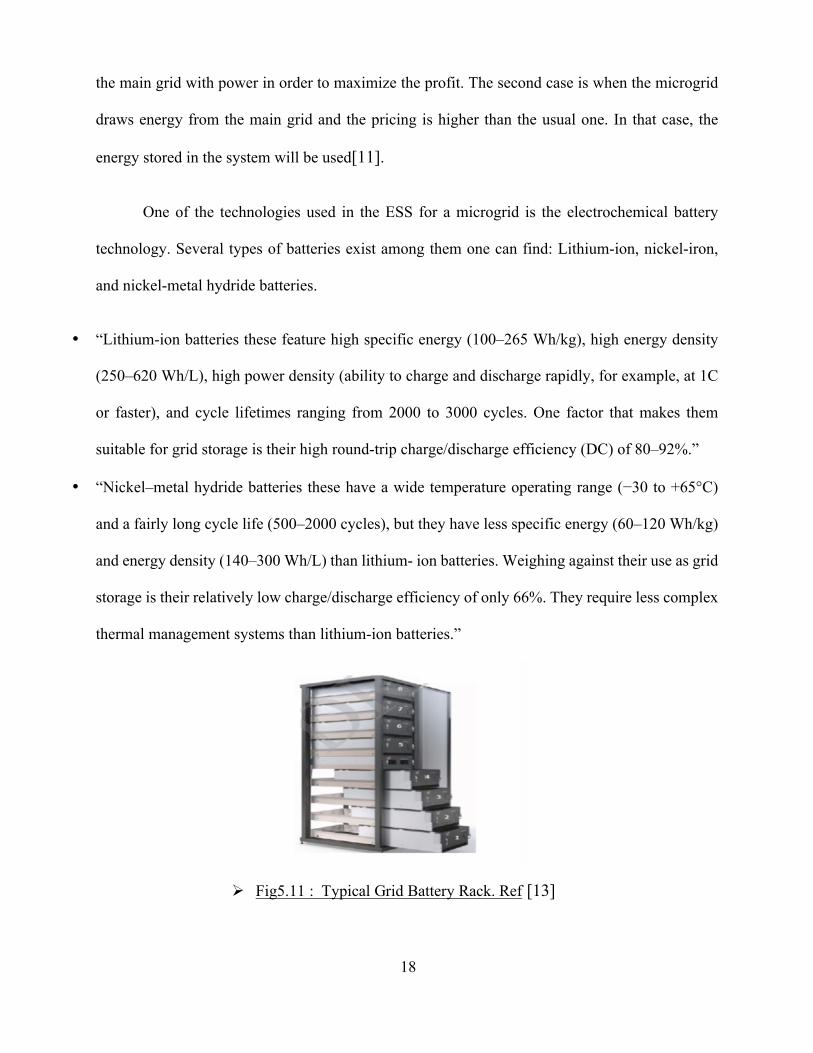
One of the technologies used in the ESS for a microgrid is the electrochemical battery
technology. Several types of batteries exist among them one can find: Lithium-ion, nickel-iron,
and nickel-metal hydride batteries.
• “Lithium-ion batteries these feature high specific energy (100–265 Wh/kg), high energy density
(250–620 Wh/L), high power density (ability to charge and discharge rapidly, for example, at 1C
or faster), and cycle lifetimes ranging from 2000 to 3000 cycles. One factor that makes them
suitable for grid storage is their high round-trip charge/discharge efficiency (DC) of 80–92%.”
• “Nickel–metal hydride batteries these have a wide temperature operating range (−30 to +65°C)
and a fairly long cycle life (500–2000 cycles), but they have less specific energy (60–120 Wh/kg)
and energy density (140–300 Wh/L) than lithium- ion batteries. Weighing against their use as grid
storage is their relatively low charge/discharge efficiency of only 66%. They require less complex
thermal management systems than lithium-ion batteries.”
Ø Fig5.11 : Typical Grid Battery Rack. Ref [13]
19
Taking into consideration the different advantages of the lithium-ion batteries such as:
• Cell voltage = 3.7 V �
• High specific energy 100-160 Wh/kg
• High specific power 250-340 W/kg
• High energy efficiency
• Good high-temperature performance
• Relatively low self-discharge (5%-10% per month)
• Low maintenance and no periodic discharge is needed; no memory.
We can conclude that it is more appropriate to use lithium-ion batteries.
v Battery mathematical model:
Many parameters such as the nominal voltage and the total capacity are used in order to
describe the battery. The most important one is the state of charge (SOC) which corresponds to a
value of 0% when the battery in not charged (empty) and to a value of 100% when it is fully
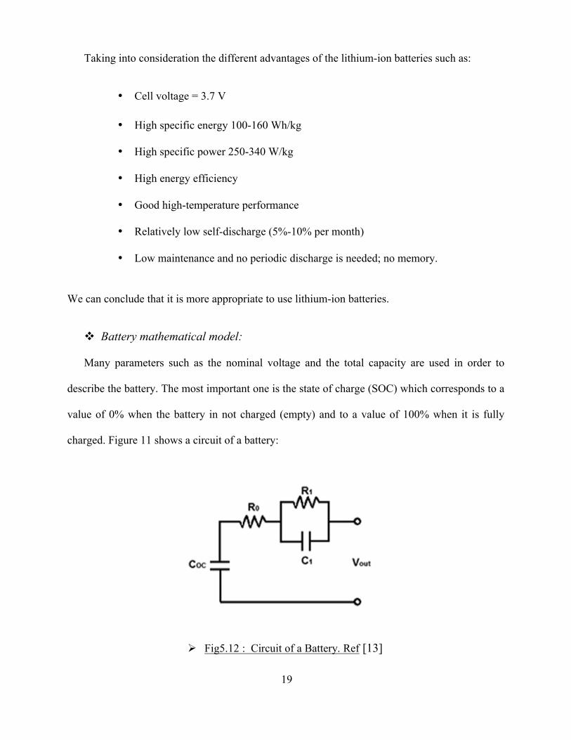
charged. Figure 11 shows a circuit of a battery:
Ø Fig5.12 : Circuit of a Battery. Ref [13]
20
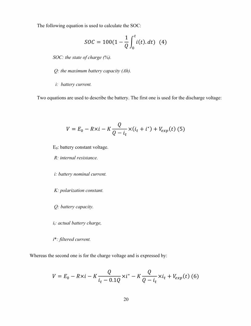
The following equation is used to calculate the SOC:
]^\ = 100(1 −1_
` a . ba)c
'(4)
SOC: the state of charge (%).
Q: the maximum battery capacity (Ah).
i: battery current.
Two equations are used to describe the battery. The first one is used for the discharge voltage:
4 = e' − 6×` − R_
_ − `c× `c + `∗ + 4Agh a (5)
E0: battery constant voltage.
R: internal resistance.
i: battery nominal current.
K: polarization constant.
Q: battery capacity.
it: actual battery charge,
i*: filtered current.
Whereas the second one is for the charge voltage and is expressed by:
4 = e' − 6×` − R_
`c − 0.1_×`∗ − R
__ − `c
×`c + 4Agh a (6)
21
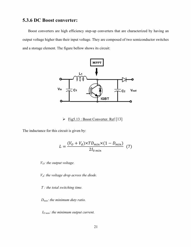
5.3.6 DC Boost converter:
Boost converters are high efficiency step-up converters that are characterized by having an
output voltage higher than their input voltage. They are composed of two semiconductor switches
and a storage element. The figure bellow shows its circuit:
The inductance for this circuit is given by:
j =(4k + 4l)×1mnoK×(1 − mnoK)
2#'noK(7)
VO: the output voltage.
Vd: the voltage drop across the diode.
T : the total switching time.
Dmin: the minimum duty ratio.
IO min: the minimum output current.
Ø Fig5.13 : Boost Converter. Ref [13]
22
Then we need to calculate the duty cycle, D, for the maximum input voltage. The maximum
input voltage is used because this leads to the minimum switch current:
mnoK = 1 −4oKnqg×r
4k(8)
VIN(min): the minimum input voltage.
VOUT: the desired output voltage.
Η: the efficiency of the converter.
Finally, we compute C2: (C1 depends on the output voltage and the characteristics of the
system)
\stc =#stcnqg×mnoKu8×Δ4stc
(9)
Ioutmax : the maximum output current
fS : the switching frequency of the bridge
x4 out : the output voltage ripple.
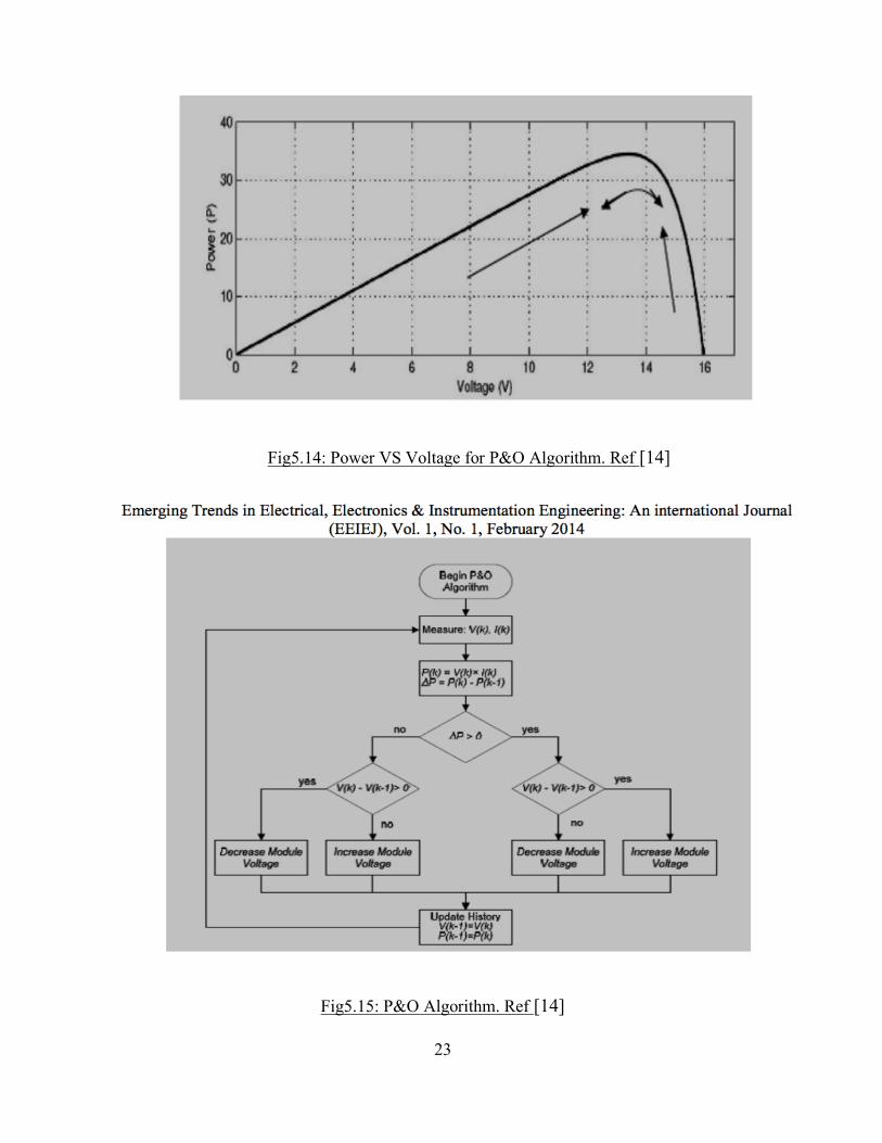
v Perturb & Observe Method
The most used MPPT is the perturb and observe (P&O) method. It consists of applying a
perturbation over the module voltage and observing the output which is then compared to the
previous perturbing cycle. If, due to that, the power is increasing the perturbation is sustained
until the peak power is reached. AT this point the MPP is zero and starts decreasing sharply and
then the perturbation reverses. The figures bellow illustrate what has been said: [14]
23
Fig5.14: Power VS Voltage for P&O Algorithm. Ref [14]
Fig5.15: P&O Algorithm. Ref [14]
24
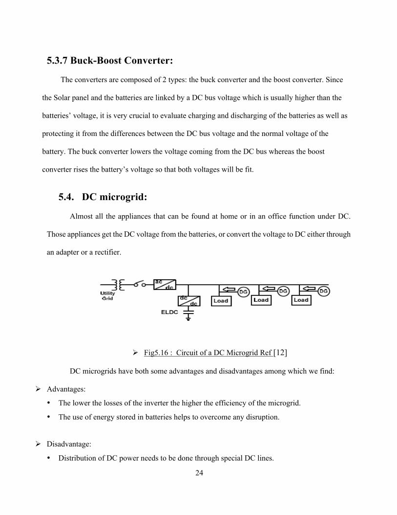
5.3.7 Buck-Boost Converter:
The converters are composed of 2 types: the buck converter and the boost converter. Since
the Solar panel and the batteries are linked by a DC bus voltage which is usually higher than the
batteries’ voltage, it is very crucial to evaluate charging and discharging of the batteries as well as
protecting it from the differences between the DC bus voltage and the normal voltage of the
battery. The buck converter lowers the voltage coming from the DC bus whereas the boost
converter rises the battery’s voltage so that both voltages will be fit.
5.4. DC microgrid:
Almost all the appliances that can be found at home or in an office function under DC.
Those appliances get the DC voltage from the batteries, or convert the voltage to DC either through
an adapter or a rectifier.
DC microgrids have both some advantages and disadvantages among which we find:
Ø Advantages:
• The lower the losses of the inverter the higher the efficiency of the microgrid.
• The use of energy stored in batteries helps to overcome any disruption.
Ø Disadvantage:
• Distribution of DC power needs to be done through special DC lines.
Ø Fig5.16 : Circuit of a DC Microgrid Ref [12]

25
A comparison should be drawn between the grid-connected and islanded modes of the DC
microgrid. When it comes to the grid-connected mode, the voltage distribution will be done
through the rectifier while keeping records of the power generated by the RE systems to the
microgrid’s loads. In this case and even if the microgrid is connected to the utility grid, the
generated power will not be supplied to it [29]. For the islanded mode, the surplus in the generated
power will also be stored in batteries. If the demand of energy is met and the batteries reach their
maximum in terms of storage one, if not all, of the RE systems will end the generation of power
and resume when it is needed.
5.5. Microgrid Controls:
Before getting to the different types of microgrid controllers we should point out to some
of the performance standard that should be met by the Microgrid controllers.
First, it is very crucial to ensure that these microgrid have the appropriate microsources
that can work under some predefined points and could be filled to their maximum. Second, these
microgrids ought to exchange any power whether it is active or reactive. Third, the process of
connecting, disconnecting, and reconnecting have to be convenient. Furthermore, utility and power
should be both combined effectively and help upgrade market support by continually generating
microsources and this power. Another performance standard comes from the fact that these
microgrid controllers should somehow guarantee the optimization of the heat usage. Another
important point is regarding health and IT industry as energy should be sustained in these fields.
We can talk also about the problem of getting interrupted when there is a general blackout, here
the controllers must have back-up systems that again sustain the usage of energy. Capacity plays
26
an important role in the efficiency and reliability of any microgrid and with enough storage
capacity, the performance of the microgrid could be boosted. [15]
When talking about microgrid controllers, we should make emphasis on three main
components: Local controls, centralized controls, and the decentralized ones.
a) Local Controllers:
As stated before, microgrids should be controlled by the controllers. This type is an
important controller when it comes to the efficiency of the microgrid as it has as a primary role
to control microsources. This could be done without any software and system. Furthermore,
these local controllers work also in the islanded mode of microgrid as they could interact with
other controllers.
b) Centralized Controllers:
When talking about centralized and decentralized controllers, we should put in mind that
these are only applicable to the hierarchical systems. The only difference between the two is
that the centralized controllers have the microgrid central controllers or referred as “MGCCs”
are linked to the microsources and loads in a way that these latters have only one single
objective.
c) Decentralized controllers:
These are different from the previous ones in a way that microsources do not rely on the
MGCCs and work as independent components as these controllers work best when the
microsources have different targets and differ in terms of their properties.
27
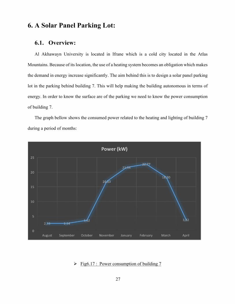
6. A Solar Panel Parking Lot:
6.1. Overview: Al Akhawayn University is located in Ifrane which is a cold city located in the Atlas
Mountains. Because of its location, the use of a heating system becomes an obligation which makes
the demand in energy increase significantly. The aim behind this is to design a solar panel parking
lot in the parking behind building 7. This will help making the building autonomous in terms of
energy. In order to know the surface are of the parking we need to know the power consumption
of building 7.
The graph bellow shows the consumed power related to the heating and lighting of building 7
during a period of months:
Ø Fig6.17 : Power consumption of building 7
28
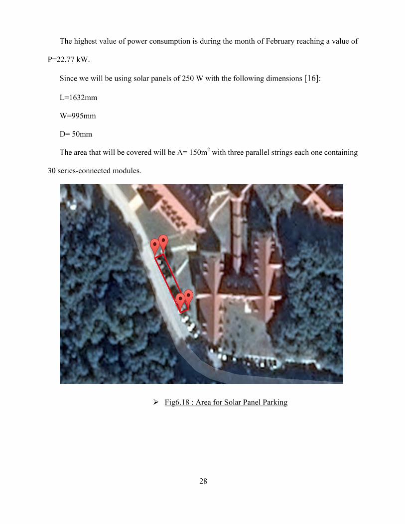
The highest value of power consumption is during the month of February reaching a value of
P=22.77 kW.
Since we will be using solar panels of 250 W with the following dimensions [16]:
L=1632mm
W=995mm
D= 50mm
The area that will be covered will be A= 150m2 with three parallel strings each one containing
30 series-connected modules.
Ø Fig6.18 : Area for Solar Panel Parking
29
6.2. Modeling of the Sun Position:
Solar energy is nothing but the share of the Sun’s radiant light and that reaches the surface of
the Earth and is available there for different application of energy generation. In other words, it
consists of converting the energy form emerging from the Sun into more valuable and beneficial
applications. For example, this can be achieved by exciting the electrons in photovoltaic cells,
photosynthesis which is one of the natural energy supply processes, or by warming objects. This
energy is free, unpolluted and available in very large quantities in most places on Earth during the
whole year. This energy is more useful during the times fossil fuel costs are high and significant
atmosphere degradation caused by the high usage of these fossil fuels is notices. Solar energy that
is carried on solar radiations consists of two parts. The first one is extraterrestrial solar radiation
which is available above the atmosphere, and the second one is the global solar radiation which is
available below the atmosphere. Besides, the values of solar radiations being measured can be
exploited to develop solar radiation models describing mathematical relationships between the
meteorological variables including sunshine ration, humidity and temperature, and solar radiation.
These models are mainly used later to forecast the solar radiation at locations where solar energy
measuring devices are not available.
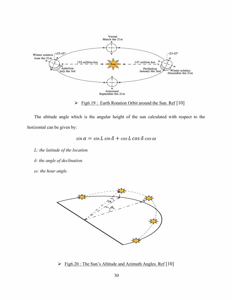
The Earth rotates in an elliptical orbit around the Sun for nearly 365 days. Some positions that
the Earth occupies during its orbit are shown bellow:
30
The altitude angle which is the angular height of the sun calculated with respect to the
horizontal can be given by:
y`/ z = y`/ j y`/ { + |}y j |}y { |}y~
L: the latitude of the location.
δ: the angle of declination.
ω: the hour angle.
Ø Fig6.20 : The Sun’s Altitude and Azimuth Angles. Ref [10]
Ø Fig6.19 : Earth Rotation Orbit around the Sun. Ref [10]
31
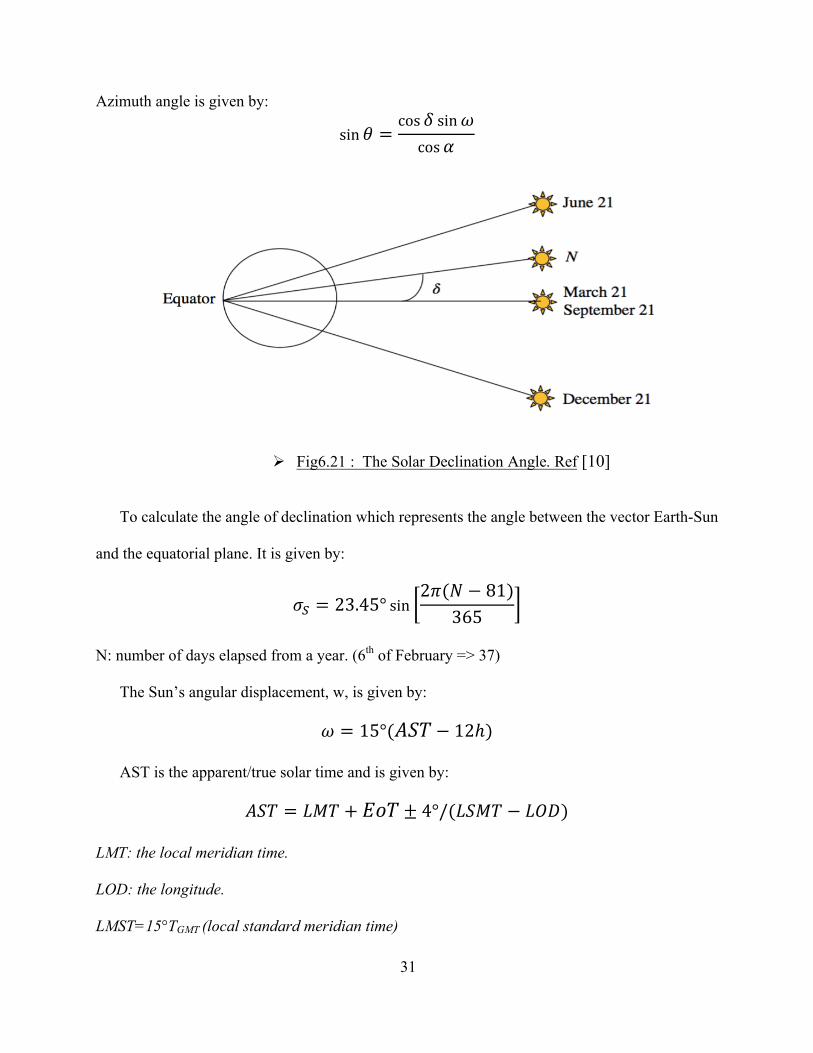
Azimuth angle is given by:
sin Ç =cos { sin~cos z
To calculate the angle of declination which represents the angle between the vector Earth-Sun
and the equatorial plane. It is given by:
Ö8 = 23.45° sin2á(à − 81)
365
N: number of days elapsed from a year. (6th of February => 37)
The Sun’s angular displacement, w, is given by:
~ = 15°(â]1 − 12ℎ)
AST is the apparent/true solar time and is given by:
â]1 = jã1 + e}1 ± 4°/(j]ã1 − j^m)
LMT: the local meridian time.
LOD: the longitude.
LMST=15°TGMT (local standard meridian time)
Ø Fig6.21 : The Solar Declination Angle. Ref [10]
32
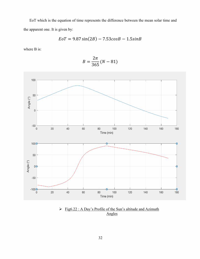
EoT which is the equation of time represents the difference between the mean solar time and
the apparent one. It is given by:
e}1 = 9.87 sin 2ç − 7.53|}yç − 1.5y`/ç
where B is:
ç =2á365
(à − 81)
Ø Fig6.22 : A Day’s Profile of the Sun’s altitude and Azimuth Angles
33
7. Simulation of the Microgrid System & Results:
7.1 Introduction:
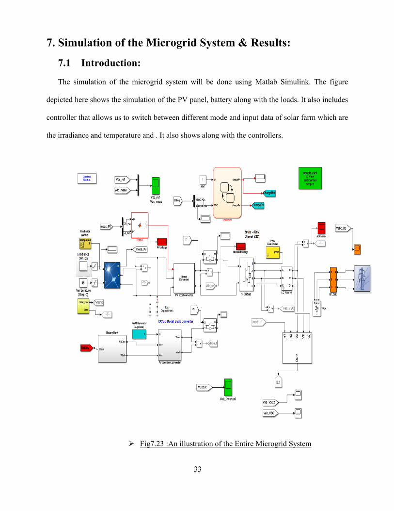
The simulation of the microgrid system will be done using Matlab Simulink. The figure
depicted here shows the simulation of the PV panel, battery along with the loads. It also includes
controller that allows us to switch between different mode and input data of solar farm which are
the irradiance and temperature and . It also shows along with the controllers.
Ø Fig7.23 :An illustration of the Entire Microgrid System
34
In the following sections we will have a closer look to each component along with a profile
plot.
7.2 Solar Panel:
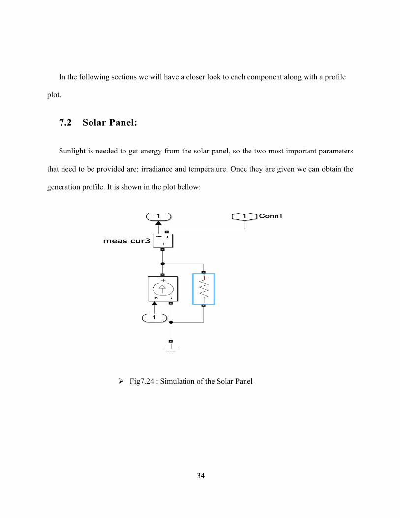
Sunlight is needed to get energy from the solar panel, so the two most important parameters
that need to be provided are: irradiance and temperature. Once they are given we can obtain the
generation profile. It is shown in the plot bellow:
Ø Fig7.24 : Simulation of the Solar Panel
35
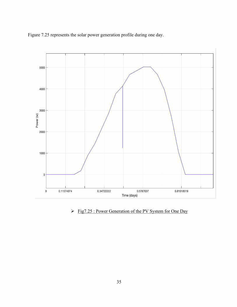
Figure 7.25 represents the solar power generation profile during one day.
Ø Fig7.25 : Power Generation of the PV System for One Day
36
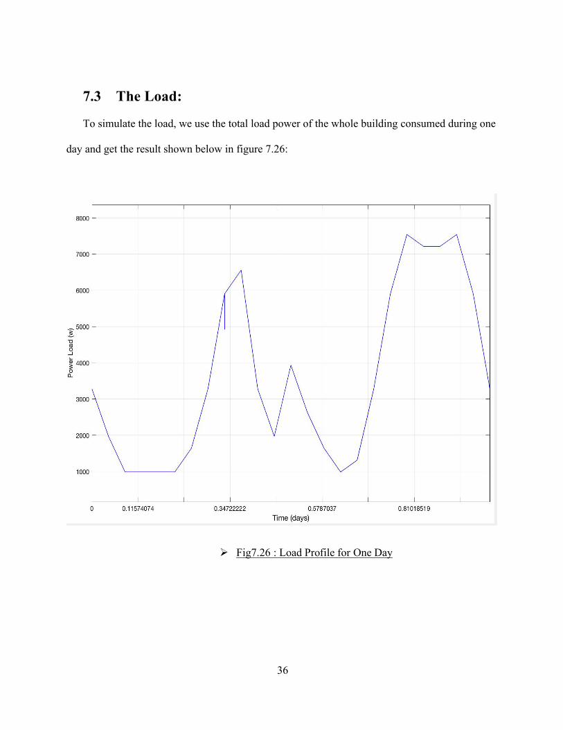
7.3 The Load:
To simulate the load, we use the total load power of the whole building consumed during one
day and get the result shown below in figure 7.26:
Ø Fig7.26 : Load Profile for One Day
37
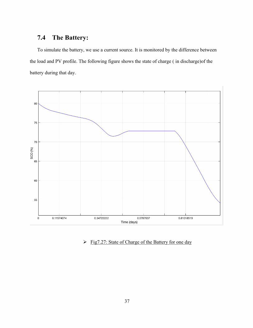
7.4 The Battery:
To simulate the battery, we use a current source. It is monitored by the difference between
the load and PV profile. The following figure shows the state of charge ( in discharge)of the
battery during that day.
Ø Fig7.27: State of Charge of the Battery for one day
38
8. Conclusion & Future Work:
Concerning the future work, a design of the solar panel parking will be done and an
experimental small scale microgrid will be realized to test whether it should be implemented or
not.
Smart Microgrids are the future of the grids since they provide concrete solutions to the
problems faced by the old grid. They can be implemented in small areas as well as large ones such
as cities. In this paper, different points related to the microgrids are discussed. It provides a general
view of the microgrid, its operations, components and the mathematical equations related to each
one in order to investigate their behavior. Finally, a model was implemented using Matlab and
Simulink to simulate the microgrid system.
39
9. REFERENCES
[1] Website: https://solarenergylocal.com/states/indiana/morocco/#glossary
[2] Mohhammad Zahran, “Smart Grid Technology, Vision Management and Control” WSEAS
TRANSACTIONS on SYSTEMS, Volume 12, Issue 1, January 2013.
[3] ABB, “When Grid gets smart-ABB vision for the power system in the future”, www.abb.com,
ABB Inc., USCS 1411, 2008. �
[4] Benefits of demand response in electricity markets and recommendations for achieving them
a report to the united states congress pursuant to section 1252 of the energy policy act of
2005
[5] Website: http://www.solarfeeds.com/the-effects-of-demand-side-energy-management/
[6] A. Banerji, D. Sen, A. K. Bera, D. Ray, D. Paul, A. Bhakat, and S. K. Biswas, “Microgrid: a
review,” Global Humanitarian Technology Conference: South Asia Satellite (GHTC- SAS)
IEEE, 2013, pp. 27-35.
[7] Ngoc An Luu. Control and management strategies for a microgrid. Electric power. Université
de Grenoble, 2014.
[8] Website: http://www.sunnypanels.com/wind-energy-generator/home-wind-turbine-
generator/
[9] https://www.infiniteenergy.com.au/what-is-the-difference-between-a-solar-panel-and-a-
photovoltaic-cell/
[10] Khatib T., Elmenreich W., MODELING OF PHOTOVOLTAIC SYSTEMS USING
MATLAB,2016.
[11] A123 systems CO., “Grid Battery Rack Installation and Operation Guide,” US, 2009
40
[12] Alharkan, H. A. (2016). A control algorithm for the solar village microgrid system (Published
master's thesis). MISSOURI UNIVERSITY OF SCIENCE AND TECHNOLOGY.
[13] K. Tazi, F. M. Abbou, A. Bannour Chaka, and F. Abdi Modeling and simulation of a
residential microgrid supplied with PV/batteries in connected/disconnected modes—Case of
Morocco Received 10 December 2016; accepted 14 March 2017; published online 28
March 2017
[14] Ahmed M. Atallah, Almoataz Y. Abdelaziz, And Raihan S. Jumaah IMPLEMENTATION
Of Perturb And Observe Mppt Of Pv System With Direct Control Method Using Buck
And Buckboost Converters Emerging Trends In Electrical, Electronics &
Instrumentation Engineering : An International Journal (EEIEJ), Vol. 1, No. 1,
February 2014
[15] R. Zamora and A. K. Srivastava, “Controls for microgrids with storage: Review, challenges,
and research needs,” Renewable and Sustainable Energy Reviews, vol. 14, issue 7, pp.
2009–2018, Sep. 2010.
[16] Website: http://www.invensun.com/solar-panels/250w-solar-panel
[17] M. Kharseh Solar Radiation Calculation
[18] Website: https://www.pinterest.com/pin/384565255656821789/
�
�


