13
1 ن الرحيمه الرحمل بسم الConceptual Design & Specifications of A Solar Pump Testing Facility for Sudan's Solar Water Pumps Project (SWP)

1
بسم الله الرحمن الرحيم
Conceptual Design & Specifications of
A Solar Pump Testing Facility
for
Sudan's Solar Water Pumps Project (SWP)

2
CONTENTS
item
Page number
1 Introduction 3
1.1 Foreword 3
1.2 Local Environment Data 4
1.3 Scope of Testing 4
1.4 The liability Period 4
2 The Conceptual Design 5
3 Bill of Quantities 8
3.1 Pump Testers 8
3.2 PV panel Tester 9
3.3 PV Module Simulator 10
3.4 Controllable DC power simulator 10
3.5 Inverter Tester 11
3.6 Weather Monitors 11
3.7 Portable measuring devices 11
3.8 Demonstrational PV Pump 12
4 Fast-moving spare parts 13
The Study Team 13

3
1 INTRODUCTION
1.1 Foreword
Sudan's Solar Water Pumps Project (SWP) is acting to lead a gradual
transformation of the privately-owned fuel-dependent irrigation schemes
in Sudan towards photovoltaic pumping. The scheme aims to supply
farmers within the coming few years with thousands of solar pumps.
To guarantee that the project follows a systematic and well-based
approach, SWP assigned The Energy Research Center (ERC) of the
University of Khartoum the task of designing a test facility in Khartoum for
PV pumps and to oversee the procurement process, lab erection, system
installment, commissioning of the facility and staff training.
This report embodies the details of the suggested testing facility. The
specifications stated are intended to be handed to potential contractors
and eventually to be implemented within SWP's time-frame for the project.
The report includes a layout of the testing facility, specs of the lab
components and other relevant information. In addition to the integrated
PV pump test details, the report includes the required testing devices for
some isolated system components. This extends the lab capabilities to
beyond its main duty of testing integrated PV pumps.
In addition to the testing instrumentation, the report suggests provision of
a full PV pumping system of reputable standard to serve as a training
work-horse and to use for system commissioning and as a test reference
system.
The testing facility is such that it can handle two tests simultaneously,
meaning that two-line tests are possible.
The laboratory, as requested by the Client and as suggested in this report,
is set to perform a full test for a complete PV pumping unit. The testing
facilities may be upgraded as to test any separate component and to
cover, as well, Stand-Alone PV systems. Details of such alternatives may
be provided, once the current scheme is established and grasped by the
lab operators.

4
1.2 Local Environment Data
# Item value 1 Location 15.5, 32.6
2 Ambient temperature ranges Hottest month May: 26-42oC Coldest month January: 16-32oC.
Altitude 390m a.s.l.
4 Irradiance The maximum global insolation in Khartoum: 900 W/m2. The mean daily global irradiance ranges between 222 W/m2 in December and 289 W/m2 in April.
5 Wind Max wind speed: 25m/s Average: ~ 4.5m/s at 20m height
1.3 Scope of Testing
i. Centrifugal multi-stage submersible pumps
ii. Centrifugal surface pumps
iii. Centrifugal float pumps
iv. Helical positive-displacement
v. Three-phase AC Induction motors
vi. Single-phase AC Induction motors
vii. D-C motors
viii. Power range: 0.5 – 50kW.
ix. Two testing lines in parallel.
x. Automatic data sensing, monitoring, recording and storage.
xi. Durability Test: All components of the system shall be subjected to
extended full operation period during which consistency of output,
temperature levels and all other relevant indicator are gauged to
ensure reliability. The continuous running shall not be less than 4 hrs.
if any appreciable temperature rise or data inconsistency is
observed, then the time range is to be extended to pinpoint causes of
inconsistency.
1.4 Liability Period
The Liability Period is one calendar year following a successful
commissioning. 15% of the total Contract Price shall be withheld by the client
pending a full clearance statement to be issued by the Consultant at the end
of the Liability period.
5
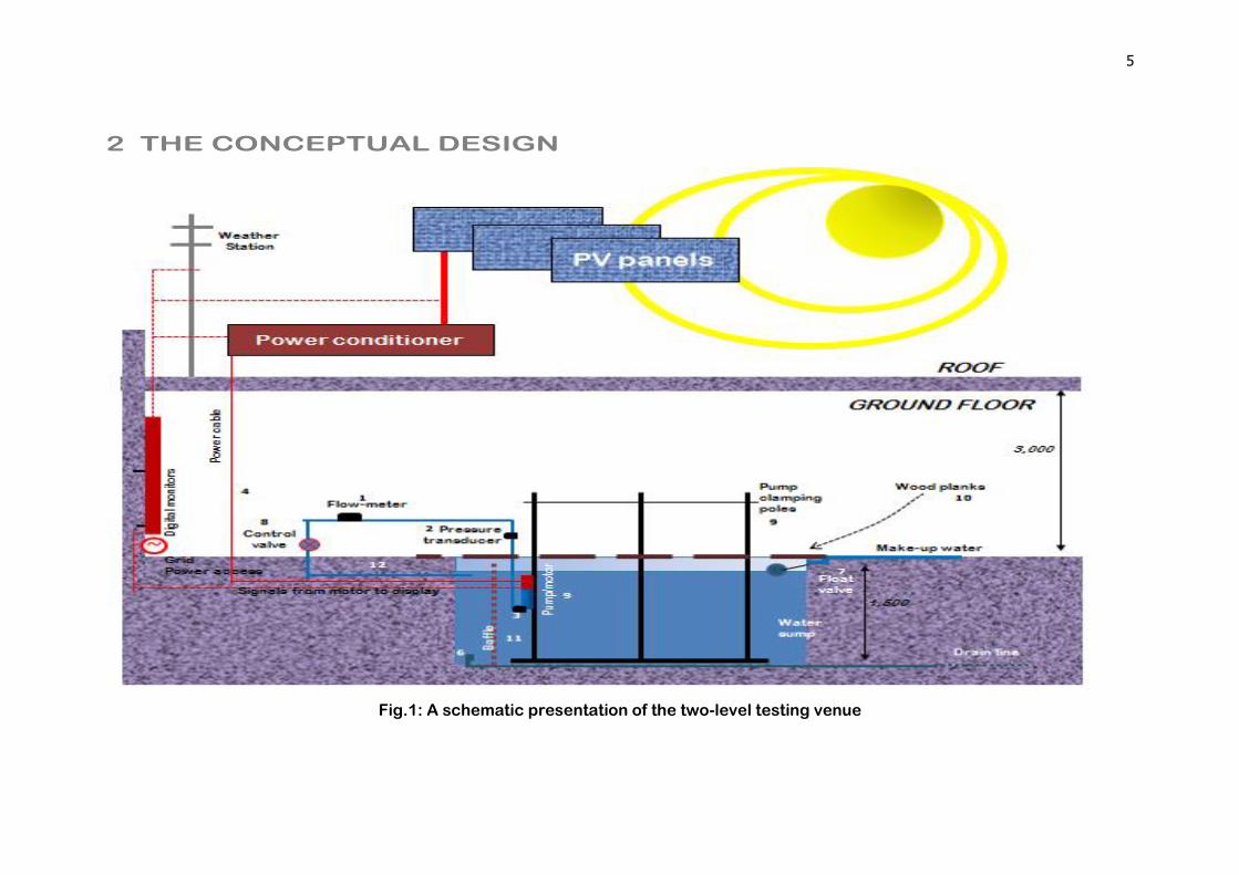
2 THE CONCEPTUAL DESIGN
Fig.1: A schematic presentation of the two-level testing venue
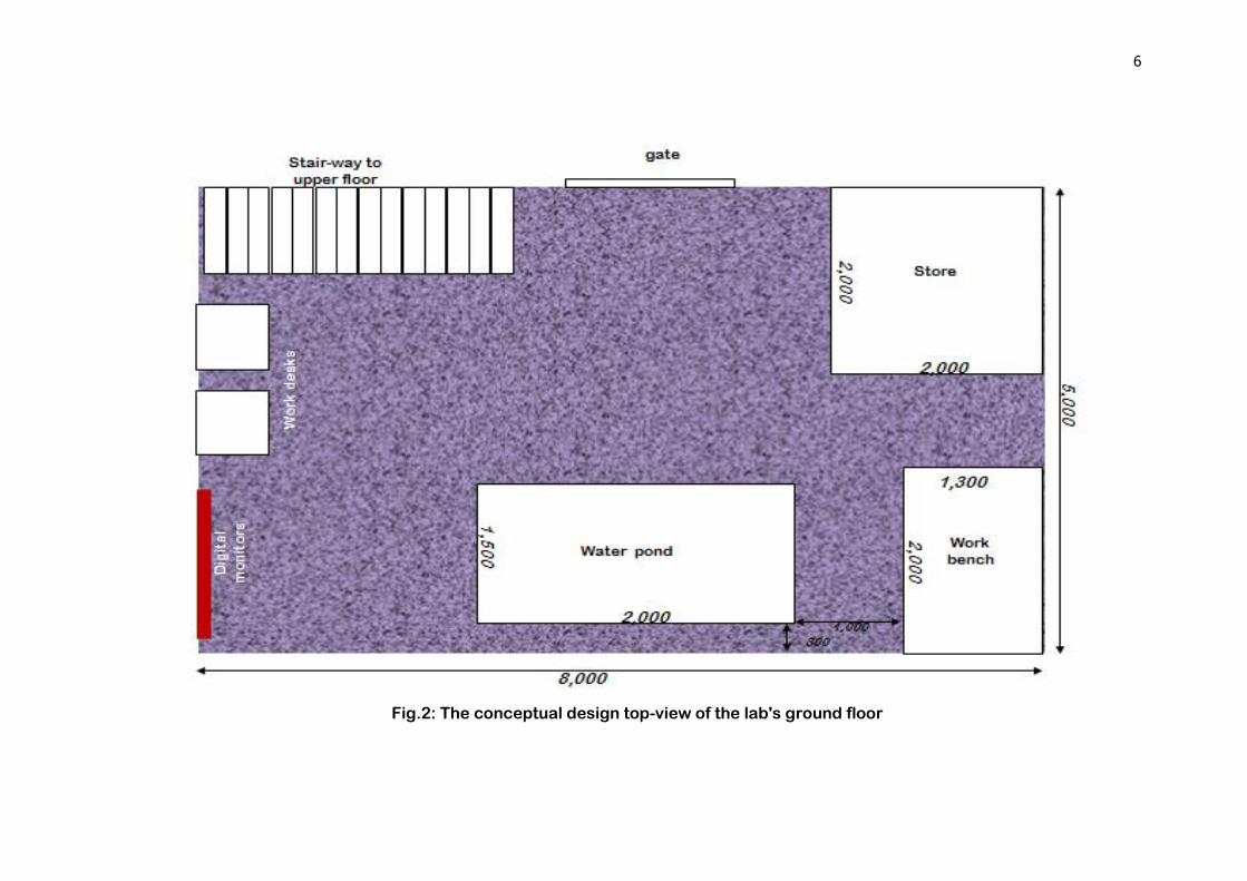
6
Fig.2: The conceptual design top-view of the lab's ground floor
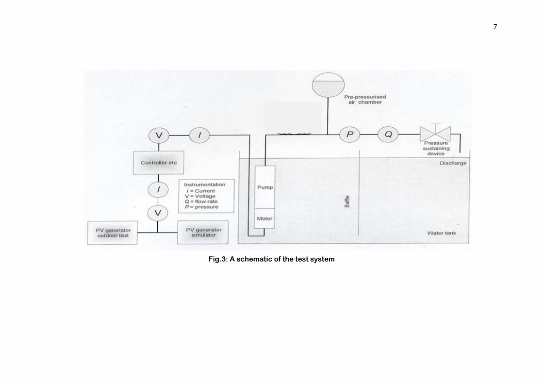
7
Fig.3: A schematic of the test system

8
3 BILL OF QUANTITIES
3.1 Pump Testers
# Item specs No. off
1 Flow meter i. Max. flow: 50L/s ii. Digital display
transduced to Main panel [L/s], 100DN
2
2 Delivery pressure gauge i. Max. pressure: 6bar ii. Digital display
transduced to Main panel [bar]
2
3 Suction pressure gauge i. Pressure range: -0.5 to 1bar
ii. Digital display transduced to Main panel [bar]
2
4 Input power to Motor(Power analyzer meter) Measuring I, V and frequency)
Digital display on Main panel [W]
2
5 Inlet water temperature sensor
Digital display on Main panel [oC]
2
6 Drain submersible pump & accessories
Capacity: 5L/s at 1m head. 2
7 Float valve for sump water make-up
25DN 2
8 Control Valve Globe, 100DN 2
9 Pump Clamping poles Three 2m angles of common welded angle base. All material galvanized steel. Complete with appropriate pump-holding clamps.
2 lots
10 Wooden planks for sump cover
Rectangular wooden planks that serve work platform
2 lots
11 Flow Baffle to inhibit turbulence
Laminated galvanized gauze sheet: 1500x1400
2 lots
12 PVC Pipes and fittings for water loop
100DN PVC, ~20m 2 lots
13 Tachometer for motor/pump speed
0-4000RPM. Digital display on Main panel [RPM]
2 lots
14 Vibration meter transduced to the Monitoring panel
Portable Accelerometer: 0-100 [Hz]
2 lots
15 Air chamber Steel drum damping pressure fluctuations to < 5%.
2 lots

9
3.2 PV Panel Tester
# Item specs No. off
1 Array Tester: Measures and displays the following I/V characteristics of PV
arrays: i. Short circuit current
ii. Open circuit voltage. iii. Current at max. power iv. Voltage at max. power v. Max. Power
vi. Fill factor vii. Array temperature
viii. Display of all above
parameters. ix. Display normalized I-V and P-
V curves. x. Supportive software.
Current rate: 50A, accuracy:1.5% at 25C. Voltage: 12- 600 V, accuracy: 1.5% at 25C. Data Acquisition System: 16 bit resolution. Peak Watt range: 50-60,000. PV panel temperature Range: 5°C to 60°C. Accuracy +/- 0.2°C.
2 lots
2 Insulation resistance testing Megger Insulation and
Continuity Tester with specs: 1.4 Insulation Nominal test
voltages 1000 V, 500 V, 250 V
(d.c). 1.2 Measuring Range: 10 kΩ -
999 MΩ on all ranges • Test Current on load: 1 mA at min. pass values of insulation (as specified in BS7671, HD 384 and IEC 364)
1 lot
3 Solar PV Electroluminescence Cameras Crack Detection Equipment
1x1.5m test area 1 lot
4 Panel supports (variable dimensions).
Clear surface area: 8mx4.5m (see Fig.2)
1 lot
5 HSE System should be IEC 61730 Parts I & Il, compliant.

11
3.3 PV Module Light Simulator
3.4 Controllable DC power simulator
# Item specs No. off
1 The PV simulator provides specified equivalent current -voltage (I-V) characteristics of a PV modules up to 2.0m x 2.0m. The steady-state light is adjusted to the required intensity and is measured by a calibrated reference cell located in the test plane. The unit measures and displays the following module parameters:
i. Complete I-V curve. ii. Open-circuit voltage, Voc.
iii. Short-circuit current, Isc. iv. Maximum power point. v. Equivalent Module
efficiency. vi. Fill factor.
vii. Equivalent Module
temperature, C. viii. Data and I-V curve
corrected to standard conditions.
ix. Conforms to IEC 904-9 Class C or Class B.
x. Optional alternate thin film reference cell.
Source:
Halogen Dichroic lamps, or equivalent Intensity range: 700 to 1100 W/m2. Lamp lifetime, typical: 1000 hrs. Illumination Uniformity:
2% over area. Measurement Range:
Voltage: 0 - 120 Vdc. Current: 0 - 20 Adc.
Accuracy:
Voltage: 1% full scale. Current: 1% full scale.
2 lots
# Item specs No. off
1 A DC power supplier, rectifying AC supply from the Grid to simulate a given PV solar supply when the required power exceeds system's load level.
i. Max power output: 60kW DC
ii. Frequency of AC supply: 50 Hz.
iii. Output Voltage and current: Fully controllable.
2 lots
11
3.5 Inverter Tester
3.6 Weather Monitors
# Item specs No. off
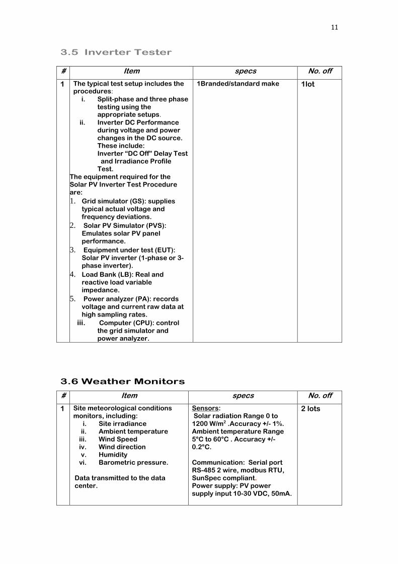
1 The typical test setup includes the procedures:
i. Split-phase and three phase testing using the appropriate setups.
ii. Inverter DC Performance during voltage and power changes in the DC source. These include: Inverter “DC Off” Delay Test
and Irradiance Profile Test.
The equipment required for the Solar PV Inverter Test Procedure are:
1. Grid simulator (GS): supplies typical actual voltage and frequency deviations.
2. Solar PV Simulator (PVS): Emulates solar PV panel performance.
3. Equipment under test (EUT): Solar PV inverter (1-phase or 3-phase inverter).
4. Load Bank (LB): Real and reactive load variable impedance.
5. Power analyzer (PA): records voltage and current raw data at high sampling rates.
iii. Computer (CPU): control the grid simulator and power analyzer.
1Branded/standard make
1lot
# Item specs No. off
1 Site meteorological conditions monitors, including:
i. Site irradiance ii. Ambient temperature
iii. Wind Speed iv. Wind direction v. Humidity
vi. Barometric pressure. Data transmitted to the data center.
Sensors: Solar radiation Range 0 to 1200 W/m2 .Accuracy +/- 1%. Ambient temperature Range 5°C to 60°C . Accuracy +/- 0.2°C. Communication: Serial port RS-485 2 wire, modbus RTU, SunSpec compliant. Power supply: PV power supply input 10-30 VDC, 50mA.
2 lots
12
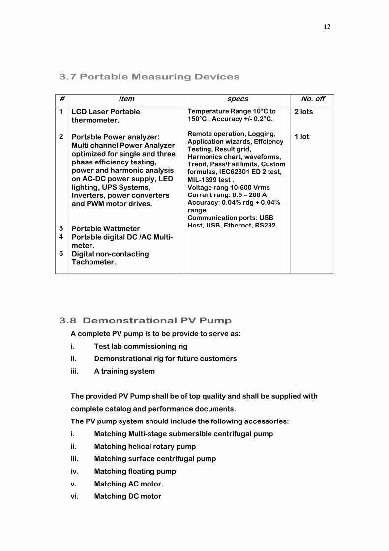
3.7 Portable Measuring Devices
3.8 Demonstrational PV Pump
A complete PV pump is to be provide to serve as:
i. Test lab commissioning rig
ii. Demonstrational rig for future customers
iii. A training system
The provided PV Pump shall be of top quality and shall be supplied with
complete catalog and performance documents.
The PV pump system should include the following accessories:
i. Matching Multi-stage submersible centrifugal pump
ii. Matching helical rotary pump
iii. Matching surface centrifugal pump
iv. Matching floating pump
v. Matching AC motor.
vi. Matching DC motor
# Item specs No. off
1 2 3 4 5
LCD Laser Portable thermometer.
Portable Power analyzer: Multi channel Power Analyzer optimized for single and three phase efficiency testing, power and harmonic analysis on AC-DC power supply, LED lighting, UPS Systems, Inverters, power converters and PWM motor drives. Portable Wattmeter Portable digital DC /AC Multi-meter. Digital non-contacting Tachometer.
Temperature Range 10°C to 150°C . Accuracy +/- 0.2°C. Remote operation, Logging, Application wizards, Effciency Testing, Result grid, Harmonics chart, waveforms, Trend, Pass/Fail limits, Custom formulas, IEC62301 ED 2 test,
MIL-1399 test . Voltage rang 10-600 Vrms Current rang: 0.5 – 200 A Accuracy: 0.04% rdg + 0.04% range Communication ports: USB Host, USB, Ethernet, RS232.
2 lots
1 lot

13
4 FAST-MOVING SPARE PARTS
The Contractor is required to provide a list of anticipated fast-moving parts,
complete with quantity and price.


