9th. International Conference on Concrete Block Paving. Buenos Aires, Argentina, 2009/10/18-21 Argentinean Concrete Block Association (AABH) - Argentinean Portland Cement Institute (ICPA) Small Element Paving Technologists (SEPT) 1 A STUDY OF THE PERFORMANCE OF CONCRETE BLOCK PAVEMENTS IN CONTAINER TERMINALS HOWE, John, BSc, CEng, MICE, MIEAust. Commercial Development Manager, Brett Landscaping and Building Products, UNITED KINGDOM. Tel.: +44-7501-462136, Fax.: +44-1924-367873. [email protected]MacLEOD, Alastair, B Eng (Hons), MIEAust. Director, MacPorts Ltd, HONG KONG. Tel.: +852-2140-6553, Fax. : +852-2140-6554. [email protected]Note: The following is the notation used in this paper: ( . ) for decimals and ( ) for thousands. Summary Concrete block pavements (CBPs) have been used for heavy duty pavements in Container Termi- nals for over 25 years based on their abilities to withstand severe dynamic and static loadings, resis- tance to fuel and hydraulic oil damage, settlement as well and in many instances, being more eco- nomical than asphalt or rigid concrete pavements. Whilst CBPs have performed well for many projects, there are some instances where the perform- ance has not been as expected, and premature pavement failures have occurred. This particularly applies in terminals using heavier container handling equipment that generates channelised wheel paths such as Rubber Tyred Gantry Cranes, Automatic Guided Vehicles and Straddle Carriers. Generally based upon visual inspections only, this paper reviews recent experiences in a number of container terminals around the world where premature fatigue and pavement failures have been ex- perienced where the heavier container handling equipment is used. This paper summarises the pavement structures, design life, container handling equipment used and visual observations of the performance for each project investigated. Based upon the observations of the performance, and discussions with the owners, conclusions are made in respect to the factors that influence the performance of container terminals block pave- ments; these findings will provide guidance to designers and constructors for future projects. 1. APPLICATIONS CONSIDERED The heavier wheel loads result from the use of the larger container handling equipment such as: 1.1 Rubber Tyred Gantry Cranes (RTGC’s) If 8 Wheel RTGC’s are selected by the port operator, the engineering solution for the runways will generally be a reinforced concrete runway beam. There have been some limited applications where 8 Wheel RTGC's operate on concrete block paving, but ultimately the runway exhibits rutting and failure in the base course. The preferred choice is 16 Wheel RTGC’s which can lower the wheel loads to an acceptable level.
Transcript
9th. International Conference on Concrete Block Paving. Buenos Aires, Argentina, 2009/10/18-21 Argentinean Concrete Block Association (AABH) - Argentinean Portland Cement Institute (ICPA)
Small Element Paving Technologists (SEPT)
1
A STUDY OF THE PERFORMANCE OF CONCRETE BLOCK PAVEMENTS IN CONTAINER TERMINALS
HOWE, John, BSc, CEng, MICE, MIEAust. Commercial Development Manager, Brett Landscaping and Building Products,
UNITED KINGDOM. Tel.: +44-7501-462136, Fax.: +44-1924-367873. [email protected]
MacLEOD, Alastair, B Eng (Hons), MIEAust. Director, MacPorts Ltd, HONG KONG.
Note: The following is the notation used in this paper: ( . ) for decimals and ( ) for thousands.
Summary
Concrete block pavements (CBPs) have been used for heavy duty pavements in Container Termi-nals for over 25 years based on their abilities to withstand severe dynamic and static loadings, resis-tance to fuel and hydraulic oil damage, settlement as well and in many instances, being more eco-nomical than asphalt or rigid concrete pavements.
Whilst CBPs have performed well for many projects, there are some instances where the perform-ance has not been as expected, and premature pavement failures have occurred. This particularly applies in terminals using heavier container handling equipment that generates channelised wheel paths such as Rubber Tyred Gantry Cranes, Automatic Guided Vehicles and Straddle Carriers.
Generally based upon visual inspections only, this paper reviews recent experiences in a number of container terminals around the world where premature fatigue and pavement failures have been ex-perienced where the heavier container handling equipment is used.
This paper summarises the pavement structures, design life, container handling equipment used and visual observations of the performance for each project investigated.
Based upon the observations of the performance, and discussions with the owners, conclusions are made in respect to the factors that influence the performance of container terminals block pave-ments; these findings will provide guidance to designers and constructors for future projects.
1. APPLICATIONS CONSIDERED
The heavier wheel loads result from the use of the larger container handling equipment such as:
1.1 Rubber Tyred Gantry Cranes (RTGC’s)
If 8 Wheel RTGC’s are selected by the port operator, the engineering solution for the runways will generally be a reinforced concrete runway beam. There have been some limited applications where 8 Wheel RTGC's operate on concrete block paving, but ultimately the runway exhibits rutting and failure in the base course.
The preferred choice is 16 Wheel RTGC’s which can lower the wheel loads to an acceptable level.
9th. International Conference on Concrete Block Paving. Buenos Aires, Argentina, 2009/10/18-21 Argentinean Concrete Block Association (AABH) - Argentinean Portland Cement Institute (ICPA)
Small Element Paving Technologists (SEPT)
2
We can leave it to the Mechanical Engineers to debate the difference between capital and ongoing equipment maintenance costs for the these two equipment options; suffice to say that there are other advantages including:
1. If there is going to be ongoing differential settlement within the operating grade tolerances of the 16 Wheel RTGC’s, it reduces the need to treat areas of differential settlement between rigid concrete runways and the adjacent flexible roadway pavements.
2. Once differential settlements between concrete RTGC runways and adjacent flexible pavements exceed 20 mm to 25mm then re-leveling is required to prevent damage to container handling equipment and the contents of the containers.
3. It allows the terminal operator additional operational flexibility in areas required for stacking of fully loaded containers (FCL’s) and empty containers in the event of seasonal fluctuations. Also it provides a multi-purpose surface for any fluctuations in areas required for Customs in-spections, empty container storage, out-of- gauge containers etc.
Whilst the use of concrete block paving for 8 wheel RTGC runways may be argued, the Authors' experience is that reinforced concrete runways are required for full confidence. Examples are rare with one example in Tanzania where 120 mm thick blocks were used with acceptable rutting of about 12 m to 15 m to date. These pavements were constructed about 20 years ago and laid by an experienced European Contractor, originally for general cargo operations using reach stackers and after 10 years use with 8 wheel RTGC’s they are still performing satisfactorily – a remarkable per-formance.
1.2 Straddle Carriers
The use of CBP’s is a common solution for straddle carrier operations as it provides a uniform yard surface giving total flexibility for running the straddle carriers and grounding containers basically anywhere within the terminal.
1.3 Automated Guided Vehicles (AGV’s)
These have been used in some European terminals and experience has been covered in previous conferences, eg (Moneil 2006). Suffice to say that the extreme wheel loads, if guided along regular paths, will inevitably cause excessive rutting and ultimately pavement failure.
Pavement design guides such as the Concrete Masonry Association of Australia’s Lockpave design software and the Interpave (UK) guide Heavy Duty Pavements - The Structural Design of Heavy Duty Pavements and Other Industries, make allowances for the effect of channelized trafficking.
1.4 Reach Stackers
Reach stackers combine very high axle loads (some in excess of 90 t), the effects of which may be exacerbated by operators using hydraulic steering to turn wheels when the equipment is stationary, resulting in aggressive service loading.
Once again CBP’s have often been the pavement surface chosen ahead of rigid concrete pavements usually on the basis of cost.
Whilst the performance of CBP’s in reach stacker operating areas has been quite good there are a number of cases where failures have occurred.
9th. International Conference on Concrete Block Paving. Buenos Aires, Argentina, 2009/10/18-21 Argentinean Concrete Block Association (AABH) - Argentinean Portland Cement Institute (ICPA)
Small Element Paving Technologists (SEPT)
3
2. PERFORMANCE OBSERVATIONS
Whilst CBP’s have performed well for many projects, there are some instances where the perform-ance has not been as expected and distress and premature pavement failures have occurred. This particularly applies in terminals using heavier container handling equipment such as Rubber Tyred Gantry Cranes, Automatic Guided Vehicles and Straddle Carriers running along predefined paths in container stacking and back reach areas.
The performance of several container terminal pavements from around the world is shown in Table 1.
3. CONCRETE BLOCK PAVING LAYER
From visual inspections and in some cases, physical investigations, it was seen that the block layer had not contributed directly to pavement distress or pavement failures. However, the authors would like to caution that descriptive specifications or standards on block dimensional tolerance are not always compatible to achieving consistent compliant joint spacing between the blocks and this has been evident on other projects.
Recent experience on a large container yard project in the UK raises the issue that the current crite-ria developed on jointing material may need reviewing. The British Standard gives guidance on particle size distribution but give no advice on durability or particle shape. On this particular pro-ject the jointing material was very fine, kiln dried sand with rounded particles, but despite the ef-forts of the experienced paving contractor the joints were not “sealing up” and the sand was easily removed by the action of traffic during construction and after handing over areas to the client. The consensus was that despite the fact that the particle size distribution was compliant, the fineness and particle shape were the contributing factors to this problem.
It is believed that the focus in the development of information in the British Standard was on ensur-ing that the jointing sand “flows” and completely fills the joints between the blocks. The particle size distribution developed may have been influenced by the fact that when block paving was first introduced into the UK and Australian markets some 20 to 25 years ago, and although standards stated that the joint spacing to be in the order of 2 mm to 5 mm, blocks then didn’t have spacer nibs to assist in achieving consistent joint spacing, generally resulting in narrow joints. Nowadays blocks have spacer nibs which assist in achieving consistent, compliant joint spaces.
4. BASE COURSE
The base course will normally comprise cement bound material, wet lean mix concrete, soil cement or in some cases an unbound material.
4.1 Cement Bound Material
The previous way of specifying “lean concrete” was changed in the UK in 2004 with the introduc-tion of BS EN 14227 Hydraulically Bound Mixtures - Specifications. Table 2 provides a descriptive means of relating the old classification to the new one.
9th. International Conference on Concrete Block Paving. Buenos Aires, Argentina, 2009/10/18-21 Argentinean Concrete Block Association (AABH) - Argentinean Portland Cement Institute (ICPA)
Small Element Paving Technologists (SEPT)
4
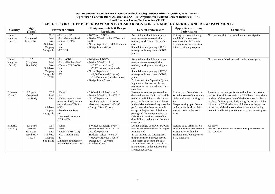
TABLE 1. CONCRETE BLOCK PAVEMENTS COMPARISON FOR S TRADDLE CARRIER AND RTGC PAVEMENTS
Country Age (Years) Pavement Section Equipment Details & Design
Repetitions General Performance Approximate Rutting Performance Comments
- 16 Wheel RTGC’s - Design Wheel Load – 16T (at rated load) - No. of Repetitions – 200,000/annum - Design Life – 20 Years
Acceptable with minimum pave-ment maintenance required in roadways and general stacking ar-eas. Some failures appearing in RTGC runways and along lines of CBM joints.
Rutting has occurred along the RTGC runway areas down to about 12-15 mm In some runways premature failure is starting to appear
No comment -failed areas still under investigation
- 16-Wheel RTGC’s - Design Wheel Load -18.2T (at rated load) -20.7T (no load, max wind) - No. of Repetitions -12,000/annum (lift cycles) - 21,000/annum (unladen moves) - Design Life - 20 years
Acceptable with minimum pave-ment maintenance required in roadways and general stacking ar-eas. Some failures appearing in RTGC runways and along lines of CBM joints. Problem with the "spherical" joint-ing material that was easily re-moved from the joints during con-struction.
No comment - failed areas still under investigation
Bahamas (Case 1)
8.5 years (Completed late 1999)
CBP Sand Base
Sub-base Capping
Sub-grade
100mm 30mm 200mm direct on lime-stone rockhead; 270mm on sub-base –CBM3 (C15) #610 Granular Base Nil Weathered Limestone CBR> 40%
- 8 Wheel Straddles(1 over 3) - Design Wheel Load – 207kN - No. of Repetitions – -Stacking Aisles: 0.675x10⁶ -Roadways/Aprons: 1.40x10⁶ - Design Life – 25years
Pavements have not performed as designed particularly in the straddle roadways which have had to be re-placed with PQ Concrete roadways. In the aisles in the stacking areas the performance has been acceptable except at the junction of the block paving and the rear quay concrete slab where straddles are travelling downhill and braking onto the con-crete apron.
Rutting up > 20mm has oc-curred in some of the straddle aisles within the stacking ar-eas. Deeper rutting up to 30mm and ultimate localized fail-ures occurred in the road-ways
Reason for the poor performance has been put down to the use of local limestone in the CBM base layers where crushing of the top surface of the base course has lead to localised failures, particularly along the location of the joints in the CBM .Also lack of drainage at the junction of the quay slab where straddle carriers are travelling downhill and braking onto the rear quay concrete apron.
Bahamas (Case 2 )
5.5 Years (First sec-tions com-pleted early
20030
CBP Sand Base
Sub-base Capping
Sub-grade
100mm 30mm 350mm CBM3 (C15) # 610 Granular Base Nil Limestone rockhead or >40% CBR Granular fill
- 8 Wheel Straddles(1 over 4) - Design Wheel Load – 207KN - No. of Repetitions Stacking Aisles: – 0.67x10⁶
Roadways/Aprons: 1.40x10⁶ - Design Life – 25 years - 3 high stacking
Design changed to provide PQ Con-crete in the roadways which are per-forming well. In the aisles in the stacking areas the performance has been accept-able except adjacent to the quay apron where there are signs of pre-mature rutting at the junction area as described above.
Rutting up to 15mm has oc-curred in some of the straddle carrier aisles within the stacking areas but appears to have stabilized.
As above. Use of PQ Concrete has improved the performance in the roadways.
9th. International Conference on Concrete Block Paving. Buenos Aires, Argentina, 2009/10/18-21 Argentinean Concrete Block Association (AABH) - Argentinean Portland Cement Institute (ICPA)
Small Element Paving Technologists (SEPT)
5
Bahamas (Case 3 )
(Not yet constructed)
CBP
Sand
Base
Sub-base
Sub-grade
100mm
30mm
350mm WLC4 (C20) (Flexural Strength >3.6MPa)
# 610 Granular Base (>300MPa)
Weathered Limestone (>1000MPa)
- 8 Wheel Straddles + (Top Lifter & Mobile Crane for Roads)
- Design Wheel Loads
265kN Straddle
769kN Top Lifter
365kN Mobile Crane
No. of Load Repetitions
Apron Slab / Roads
- 6.6x10⁶ - Straddle
- 67,500 -Top Lifter
- 31,200 - Mobile Crane
Stacking Aisles
- 3-4 high stacking predominant load (420kN)
Design will be PQ pavements in roadways and block paving in the stacking areas.
Netherlands (Case 1)
Renovation 1993 – 1995
CBP Sand Base
Subsoil
120 mm 30-50 mm 500 mm CTB Silty sand
10 Wheel Straddles (1 over 3) - Design Wheel Load - 16 T - No. of Design Repetitions: • Stacking 100 per teu ground slot per
year = 2000 passes per lane per year • Roadways 264.000 per year - Design Life - 20 years
Pavements have not performed as designed due to the ongoing settle-ment of the subsoil and in some area because of non bounded material in the top of the base layer.
Rutting up > 30mm has oc-curred in some of the straddle aisles within the stacking and transfer areas. No major rutting in the road-ways.
If rutting occurs within the first 1 or 2 years inspections have shown that the top of the base layer (up till 50 mm) is not correctly bonded to the whole base layer. In these areas early replacement is necessary to protect the rest of the base layer from failing.
Netherlands (Case 2)
Area 1982 Area 1992 Area 1996 Area 1998
CBP Sand Base
Subsoil
120 mm 30-50 mm 550 mm CTB Sand (reclaimed area)
8 Wheel Straddles (1 over 2) - Design Wheel Load 17 T- - No. of Design Repetitions - Design Life - 20 years
Pavements have performed as de-signed.
Netherlands (Case 3)
1992 CBP Sand Base
Subsoil
120 mm 30-50 mm 550 mm CTB Sand (reclaimed area)
4 Wheel AGV’s - Design Wheel Load – 20T - No. of Design Repetitions – 1,04 x 1milion per year (figures 2007) - Design Life – 20 years
Excessive rutting caused by the tracking of wheel paths along “guided wire” system and crushing failure of the top layer of sand ce-ment base course Evidence of crushing of top layer of the soil cement base course resulted in excessive rutting in both areas.
Initial pavements showed some rutting up to 30-40mm whereupon repairs would be done. In AGV lanes rutting up to 100mm After improvements to base course rutting 20-30mm after approx 7 years Due to the fixed traveling lanes for the AGV parallel and perpendicular to the quay rutting led to extreme depres-sions at the crossings.
Extreme rutting is attributed to - large number of repetitive AGV axle loads along fixed travel lanes - insufficient drainage leading to saturation of the bed-ding layer and subsequent pumping - crushing of material in the sand bedding layer and the upper part of the sand cement base course Major recommendation from Ref 1 below was to replace the top 250-300mm of sand cement base with lean con-crete (C15 strength) on top of the sand cement material. However concrete blocks will not be used for AGV pavements in the future and concrete will be used. Rea-sons for this are: - The change of AGV’s to twin carry capacity (4x20’
containers) increased the maximum wheel load to 23.5 T.
- Impact on terminal performance for maintenance ac-tivities must be reduced to a minimum in time and area.
9th. International Conference on Concrete Block Paving. Buenos Aires, Argentina, 2009/10/18-21 Argentinean Concrete Block Association (AABH) - Argentinean Portland Cement Institute (ICPA)
- 8 Wheel RTGC’s - Design Wheel Load – 31.6 T - No. of Repetitions – N/A - Design Life – 25 years
Pavements performing well includ-ing the RTGC runways
Up to 15 - 20 mm in RTGC runways. Elsewhere minimal rutting
Good performance put down to a robust design (strong base course layer), good quality blocks and high con-struction standards.
9th. International Conference on Concrete Block Paving. Buenos Aires, Argentina, 2009/10/18-21 Argentinean Concrete Block Association (AABH) - Argentinean Portland Cement Institute (ICPA)
Small Element Paving Technologists (SEPT)
7
Table 2. Old and new classifications.
PREVIOUS NAME NEW NAME FOR BS EN14227 - PARTS 1, 2 & 3 (ALL
In situ cement stabilisation has been used in some situations however care needs to be taken to pro-duce a durable and uniform base course material with consistent strength.
Where sites have existing sand with reasonable grading in the formation, in situ cement stabilization can offer very economic pavements and high rates of production.
Unfortunately it requires specialist Contractors with the latest equipment to ensure adequate mixing, moisture control and control of cement content.
4.3 Unbound Crushed Rock
There have been some pavements designed using a high quality crushed rock for the sub-base and base courses. Whilst these seem to have performed reasonably well in some projects for non chan-nelized traffic, it is suggested that this type of pavement structure would not be suitable for heavy duty channelized loads.
5. CONSTRUCTION CONSIDERATIONS
Whilst CBP’s have performed well for many projects, there are some projects where the perform-ance has not been as expected and premature pavement failures have occurred.
After reviewing the performance of a number of container terminals around the world where prema-ture fatigue and pavement failures have been experienced it appears that in most cases failure oc-curs in the base course and underlying layers and not the concrete block paving layer.
This paper has not analysed the pavement design for each project under review and it has been as-sumed that the pavement structure has been adequately designed and specified for the conditions and predicted traffic.
What is reviewed are some of the practical construction considerations which are believed to con-tribute to poor pavement performance and in extreme cases premature failure. These include:
9th. International Conference on Concrete Block Paving. Buenos Aires, Argentina, 2009/10/18-21 Argentinean Concrete Block Association (AABH) - Argentinean Portland Cement Institute (ICPA)
Small Element Paving Technologists (SEPT)
8
5.1 Time Limit for Compaction
It is imperative that the compaction of the freshly laid CBM or cement stabilised sand material is compacted as soon as possible after placement from the spreader machine; ideally this should not to exceed 1½ hours from mixing to completion of compaction.
Some extension can be allowed if a PFA Blended Cement is used due to the slower rate of hydra-tion [MacLeod, 1983].
The roller types/combinations and number of passes need to be confirmed by a trial pavement be-fore the main pavement construction commences.
5.2 Joints in Base Course
The correct treatment and location of vertical construction joints between adjacent rips of the base course is essential. Most of the failures observed were located directly above longitudinal joints in the base course layer, particularly in pavements where modified bases have been laid using self propelled spreader machines.
Whilst this offers high production and economies over wet lean mix special attention needs to be given to:
1. Joint treatment
It is important when laying CBM that the edges are cut back to sound fully compacted material as shown in Figure 1.
Figure 1. Cut Back Edges.
Unformed joints or joints that display un-compacted material need to be cut back to a clean straight edge to expose adequately compacted material before constructing the adjacent bay of CBM. The minimum cut back of longitudinal and transverse joints shall be to properly compacted material or a width of no less than one layer depth.
9th. International Conference on Concrete Block Paving. Buenos Aires, Argentina, 2009/10/18-21 Argentinean Concrete Block Association (AABH) - Argentinean Portland Cement Institute (ICPA)
Small Element Paving Technologists (SEPT)
9
2. Location of joints
The longitudinal joints between adjacent rips and transverse joints are always a potential pavement weakness. Therefore, the location of these joints should be positioned away from the designed alignment of wheel tracks such as RTGC runway paths or Straddle Carrier travel paths.
Where the required thickness of CBM needs to be made up in more than one layer, joints in the lay-ers should be staggered vertically. A plan showing the proposed positions of the joints should be prepared and approved before commencement of any pavement construction.
3. Damage to joints during compaction of CBM
CBM base layers can be laid in rips of approximately 3.0 m to 3.5m wide on a “hit and miss” prin-ciple whereby alternate rips are placed, compacted and edges cut back. Infill rips are then placed and compacted as shown in Figure 2.
Great care needs to be taken to achieve full compaction of the edges of the CBM rip without caus-ing damage to the CBM in the adjacent bay. It has been observed during the compaction of the edges that the heavy roller overlaps the adjacent top edge on the recently placed CBM layer in the adjacent rip which causes damage to these adjacent top edges.
Extreme care needs to be taken when rolling not to overlap and crush the adjacent top edge. Using wet lean concrete as a base course avoids this potential problem as joints are fully compacted to the surface without any disturbance.
Figure 2. Infilling and compacting using 'hit and miss' method.
4. Segregation
The mix design and placing of the CBM material needs to be closely monitored to ensure that no segregation occurs in the surface of the base course layer as shown in Figure 3, below.
9th. International Conference on Concrete Block Paving. Buenos Aires, Argentina, 2009/10/18-21 Argentinean Concrete Block Association (AABH) - Argentinean Portland Cement Institute (ICPA)
Small Element Paving Technologists (SEPT)
10
With the passage of heavy wheel loads displacement and crushing of this surface layer will occur under the sand bedding layer ultimately leading to localized failure.
5. Roller induced cracks
Sometimes during the compaction process using steel drum vibrating rollers, small transverse cracks and crusting of the surface maybe induce. Before the cement bound material sets, and ide-ally as soon as possible after the completion of the rolling with steel drum rollers, these cracks can be closed up by using a pneumatic multi-tyred roller (See Figure 4).
Figure 3. Segregation in finished surface of CBM.
Figure 4. Roller induced cracks.
6. Use of Bitumen Seals on Base Course
The use of bitumen seals to assist in the curing of cement bound materials and to assist in water proofing the pavement was introduced in the early 90’s in Australia. In some projects geotextiles impregnated with bitumen was specified. A performance review conducted by Kang in 2006 re-ported that the geotextile laid under the laying course material had broken down.
It is important to ensure an even application rate, sufficient only to cure the CBM. Excessive thick-nesses of bitumen will lead to contamination of the bedding sand layer and reduce its drainage and load transfer properties. A bitumen sprayer with a calibrated flow meter should be used as shown in Figure 5.
7. Drainage of Sand Bedding Layer and Sub Grade
For the pavement to perform satisfactorily the sand bedding layer needs to be adequately drained into the permanent site drainage system in a positive manner. This is to:
a) Avoid build up of instantaneous pore water pressure when heavy wheel loads are applied leading to displacement of jointing sand from the joints together with other fines which will be pumped to the surface.
b) Minimise the amount of rain water entering the lower pavement layers and sub-grade.
This problem is particularly prevalent at the bottom of downhill grades at valleys, or against edge restraints where free water will stand if not drained away quickly. A typical failure is shown in Figure 6, below.
9th. International Conference on Concrete Block Paving. Buenos Aires, Argentina, 2009/10/18-21 Argentinean Concrete Block Association (AABH) - Argentinean Portland Cement Institute (ICPA)
Small Element Paving Technologists (SEPT)
11
Figure 5. Application of Bitumen Curing Layer.
Note that the edges of the CBM have been marked ready for saw cutting.
Plate 6 – Failure at Interface with Edge Restraint.
9th. International Conference on Concrete Block Paving. Buenos Aires, Argentina, 2009/10/18-21 Argentinean Concrete Block Association (AABH) - Argentinean Portland Cement Institute (ICPA)
Small Element Paving Technologists (SEPT)
12
A method that has been used in the past is a “drainage hole” method. A line of 50mm diameter ver-tical drainage holes at the underside of the sand bedding layer is drilled through the CBM base course into a no-fines concrete under-drain. A disadvantage of this method is that it may create a potential weakness in the pavement.
Drainage of the sand bedding can be achieved by drilling or forming holes, 30mm diameter, to drain the bedding sand directly into drainage channels or drainage pits. Typically these holes would be at 1.0 m centres or at the four (4) sides of a drainage pit [Howe, 1993].
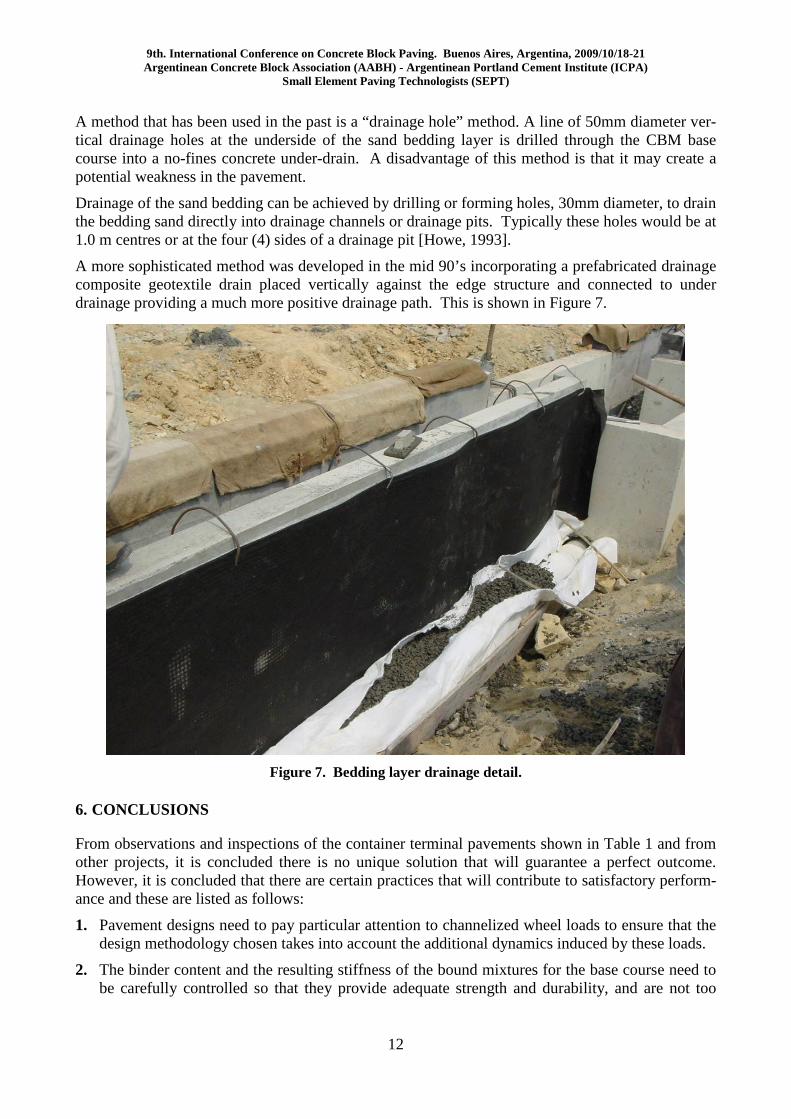
A more sophisticated method was developed in the mid 90’s incorporating a prefabricated drainage composite geotextile drain placed vertically against the edge structure and connected to under drainage providing a much more positive drainage path. This is shown in Figure 7.
Figure 7. Bedding layer drainage detail.
6. CONCLUSIONS
From observations and inspections of the container terminal pavements shown in Table 1 and from other projects, it is concluded there is no unique solution that will guarantee a perfect outcome. However, it is concluded that there are certain practices that will contribute to satisfactory perform-ance and these are listed as follows:
1. Pavement designs need to pay particular attention to channelized wheel loads to ensure that the design methodology chosen takes into account the additional dynamics induced by these loads.
2. The binder content and the resulting stiffness of the bound mixtures for the base course need to be carefully controlled so that they provide adequate strength and durability, and are not too
9th. International Conference on Concrete Block Paving. Buenos Aires, Argentina, 2009/10/18-21 Argentinean Concrete Block Association (AABH) - Argentinean Portland Cement Institute (ICPA)
Small Element Paving Technologists (SEPT)
13
strong that may result in a "brittle" rigid pavement. The minimum and maximum strength of bound materials should be specified and monitored as the binder content and strengths will in-fluence the potential for shrinkage and cracking.
3. For bound materials limit the time from batching to completion of compaction, ideally not more1½ hours.
4. The design strengths and construction methodology needs to ensure that "block" cracking of the bound base is avoided and micro cracking is encouraged.
5. Construction joints in bound materials are a potential source of pavement weakness, hence the treatment of joints both in location and construction methods is paramount to ensure that they don't have a negative impact on the pavements performance. Joints should be vertical, straight and either "formed" or cut back. The use of wet lean concrete in-lieu of CBM can assist in avoiding joint damage that is associated when using CBM.
6. Drainage of the sand bedding layer into the permanent drainage system is essential. Particular attention needs to be given to provide adequate drainage of the bedding sand without inducing structural weaknesses in the pavement.
7. It is recommended not to use geotextiles under the sand bedding layer in trafficked areas.
7. REFERENCES
MOENIELAL, M, 2006. Concrete Block Pavements in the Port of Rotterdam, 8th International Conference on Concrete Block Paving.
CONCRETE MASONRY ASSOCIATION OF AUSTRALIA, Lockpave Version V17.1.
INTERPAVE DECEMBER 2007, Heavy Duty Pavements - The Structural Design of Heavy Duty Pavements and Other Industries - Edition 4.
BRITISH STANDARD, 2004, BS EN 14227 Hydraulically Bound Mixtures - Specifications.
KANG, C Y, 2006. Performance Review of Hong Kong International Airport and Yantian Interna-tional Container Yards.
MacLEOD, A, 1983. Design and Construction of Heavy Duty Pavements, Fisherman Islands Con-tainer Terminals – The Institution of Engineers, Australia Civil Engineering Transactions.
HOWE, J, 1993. Interlocking Concrete Pavements - A Guide to Design and Construction for Road and Industrial Pavements, Edition 6 - Boral Calsil.