D2.1 For technical assistance in the U.S., call 866-405-6654 (outside the U.S., see inside back cover for directory) P AN-L UG ™ C OMPRESSION C ONNECTORS Panduit ® Pan-Lug ™ Compression Connectors provide permanent terminations for a variety of power and grounding applications, with innovation, highest reliability, and lowest installed cost. Panduit offers the first and only copper compression lugs and splices that meet Network Equipment-Building Systems (NEBS) Level 3 requirements as tested by Telcordia Technologies. NEBS Level 3 assures that product performance is suitable for equipment applications that demand minimal service interruptions over the life span of the equipment. • Functional product information is marked directly on the connector, facilitating the identification, ordering, and usage of the compression connector • Color-coded to facilitate quick identification of the proper crimping die • Made from high strength, high conductivity electrolytic copper and aluminum alloy materials to provide optimum connectivity for power and grounding applications • UL Listed or Recognized, CSA Certified, ABS Type Approved and tested by Telcordia – meets NEBS Level 3, as noted • Terminations using Panduit ® Pan-Lug ™ Compression Connectors are also UL Listed and CSA Certified with specified competitor tools • Wide assortment of manual, controlled cycle, battery operated hydraulic and pneumatic crimping tools for reliable connections at the lowest installed cost Panduit ® Pan-Lug ™ Compression Connectors are designed for use with many different code and flex conductor types and are available in a broad range of styles and sizes including copper one-hole, two-hole, and blank tongue lugs and splices; aluminum one-hole and two-hole lugs and splices; and copper in-line reducing splices. Panduit offers a wide assortment of Pan-Lug ™ Power Connectors to meet customer needs and today’s application requirements. ELECTRICAL SOLUTIONS B2. Cable Accessories C1. Wiring Duct C3. Abrasion Protection C4. Cable Management D1. Terminals D2. Power Connectors E1. Labeling Systems E2. Labels E3. Pre-Printed & Write-On Markers F. Index B3. Stainless Steel Ties C2. Surface Raceway E5. Lockout/ Tagout & Safety Solutions B1. Cable Ties A. System Overview D3. Grounding Connectors E4. Permanent Identification Courtesy of Steven Engineering, Inc. - (800) 258-9200 - [email protected] - www.stevenengineering.com
Transcript
D2.1For technical assistance in the U.S., call 866-405-6654 (outside the U.S., see inside back cover for directory)
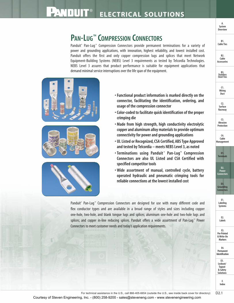
PAN-LUG™ COMPRESSION CONNECTORSPanduit® Pan-Lug ™ Compression Connectors provide permanent terminations for a variety of power and grounding applications, with innovation, highest reliability, and lowest installed cost.Panduit offers the first and only copper compression lugs and splices that meet Network Equipment-Building Systems (NEBS) Level 3 requirements as tested by Telcordia Technologies.NEBS Level 3 assures that product performance is suitable for equipment applications that demand minimal service interruptions over the life span of the equipment.
• Functional product information is marked directly on theconnector, facilitating the identification, ordering, andusage of the compression connector
• Color-coded to facilitate quick identification of the propercrimping die
• Made from high strength, high conductivity electrolyticcopper and aluminum alloy materials to provide optimumconnectivity for power and grounding applications
• UL Listed or Recognized, CSA Certified, ABS Type Approvedand tested by Telcordia – meets NEBS Level 3, as noted
• Terminations using Panduit ® Pan-Lug™ CompressionConnectors are also UL Listed and CSA Certified withspecified competitor tools
• Wide assortment of manual, controlled cycle, batteryoperated hydraulic and pneumatic crimping tools forreliable connections at the lowest installed cost
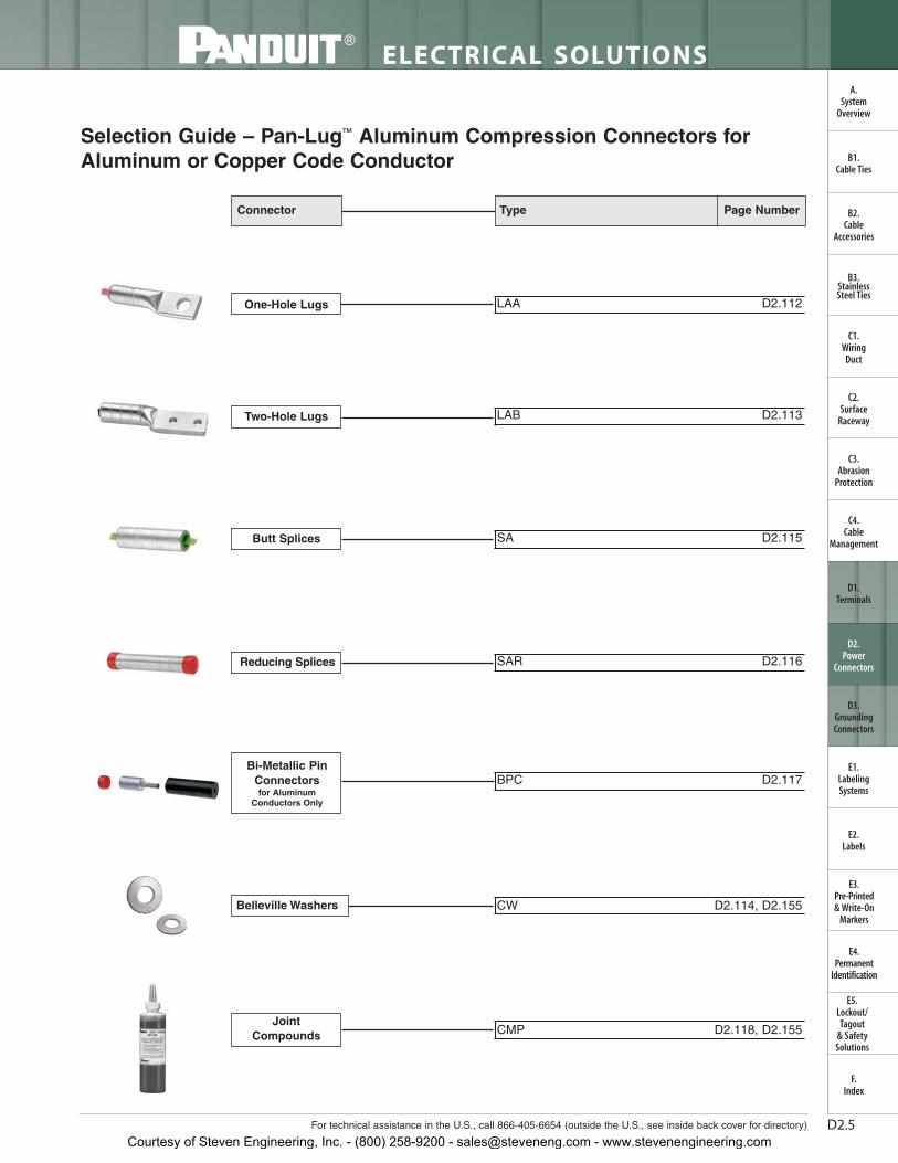
Panduit® Pan-Lug ™ Compression Connectors are designed for use with many different code and
flex conductor types and are available in a broad range of styles and sizes including copper
one-hole, two-hole, and blank tongue lugs and splices; aluminum one-hole and two-hole lugs and
splices; and copper in-line reducing splices. Panduit offers a wide assortment of Pan-Lug ™ Power
Connectors to meet customer needs and today’s application requirements.
ELECTRICAL SOLUTIONS
B2.Cable
Accessories
C1.Wiring
Duct
C3.Abrasion
Protection
C4.Cable
Management
D1.Terminals
D2.Power
Connectors
E1.LabelingSystems
E2.Labels
E3.Pre-Printed & Write-On
Markers
F.Index
B3.StainlessSteel Ties
C2.Surface
Raceway
E5.Lockout/Tagout
& SafetySolutions
B1.Cable Ties
A.System
Overview
D3.GroundingConnectors
E4.Permanent
Identification
Courtesy of Steven Engineering, Inc. - (800) 258-9200 - [email protected] - www.stevenengineering.com
Panduit designs andmanufactures a full line oflabeling products, softwareand printers to assist you withyour labeling requirements.See pages E1.1 – E2.22.
Heat shrink tubing providesan economical and easy wayto insulate, protect, harnessand color code electrical andelectronic components.See pages C3.22 – C3.44.
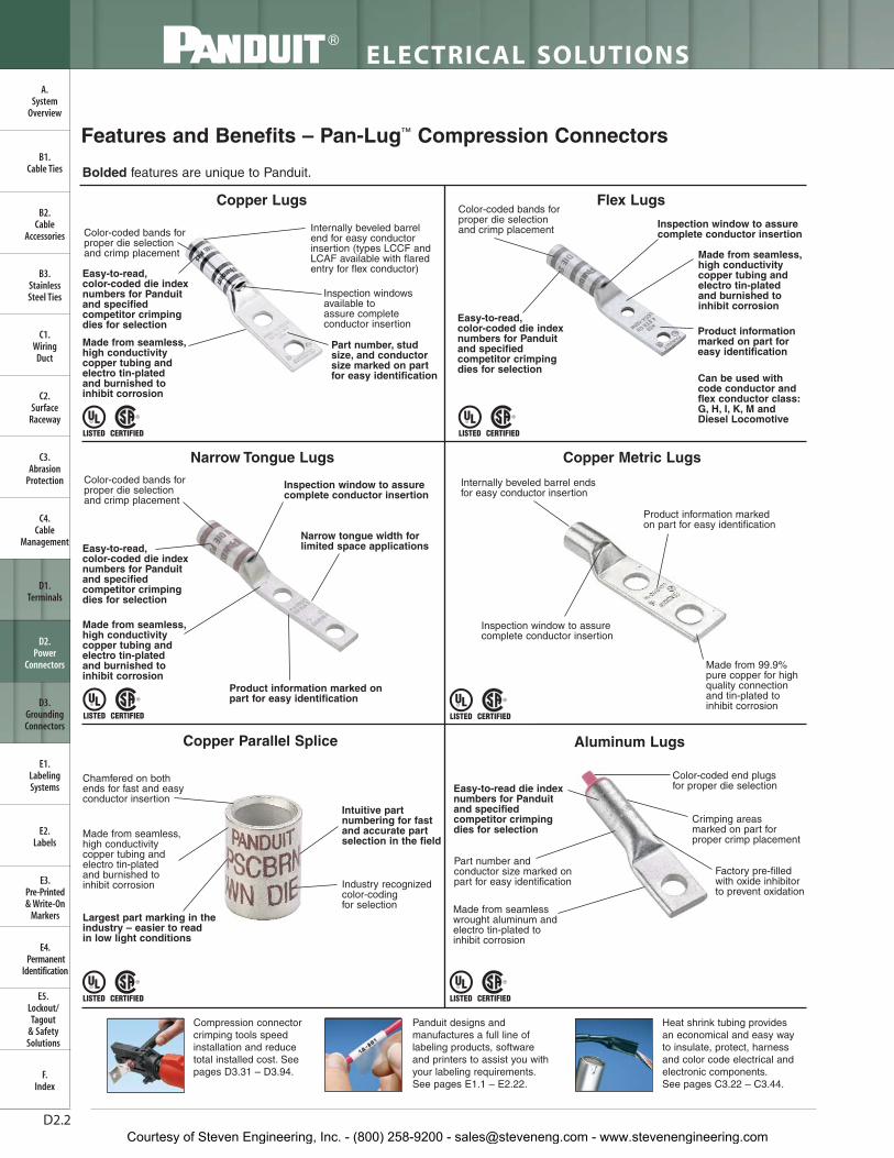
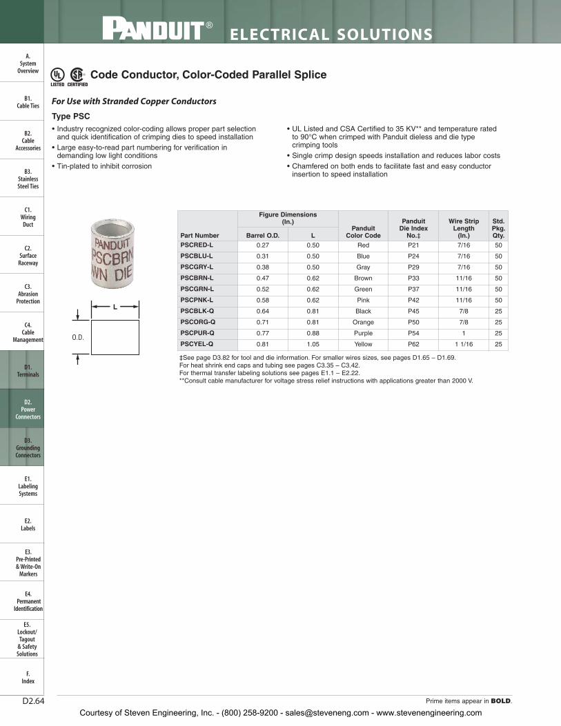
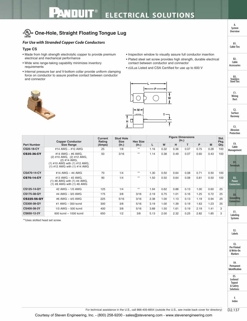
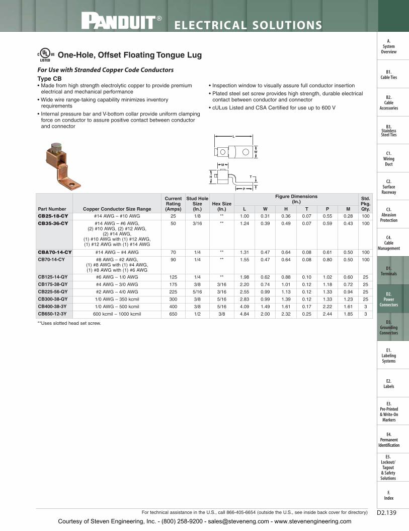
Chamfered on both ends for fast and easy conductor insertion
Made from seamless,high conductivity copper tubing and electro tin-plated and burnished to inhibit corrosion Industry recognized
color-coding for selection
Intuitive part numbering for fastand accurate partselection in the field
Flex Lugs
Narrow Tongue Lugs
Color-coded bands forproper die selectionand crimp placement
Color-coded bands forproper die selectionand crimp placement
Color-coded bands forproper die selectionand crimp placement
Courtesy of Steven Engineering, Inc. - (800) 258-9200 - [email protected] - www.stevenengineering.com
D2.6
ELECTRICAL SOLUTIONS
Prime items appear in BOLD.
B2.Cable
Accessories
C1.Wiring
Duct
C3.Abrasion
Protection
C4.Cable
Management
D1.Terminals
D2.Power
Connectors
E1.LabelingSystems
E2.Labels
E3.Pre-Printed & Write-On
Markers
F.Index
B3.StainlessSteel Ties
C2.Surface
Raceway
E5.Lockout/Tagout
& SafetySolutions
B1.Cable Ties
A.System
Overview
D3.GroundingConnectors
E4.Permanent
Identification
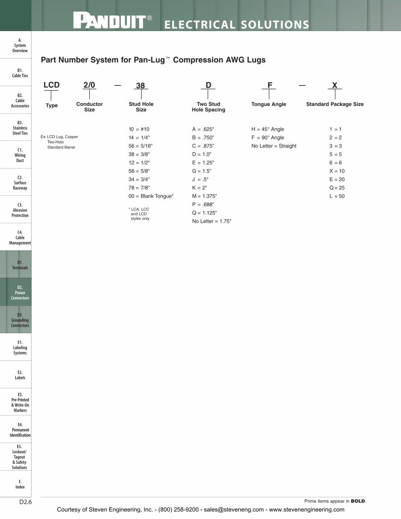
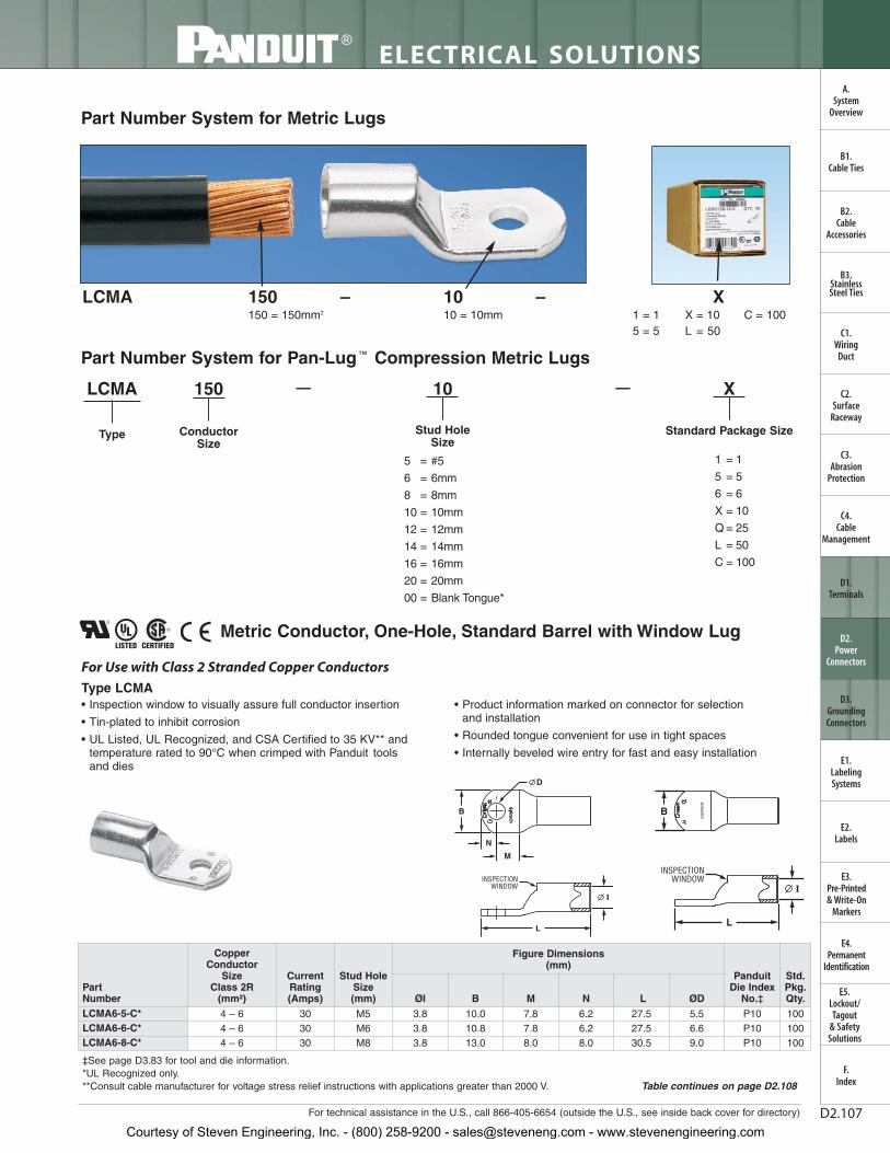
Part Number System for Pan-Lug ™ Compression AWG Lugs
2/0 — —38 D F X
ConductorSize
Stud Hole Size
Two Stud Hole Spacing
Tongue Angle
LCD
Type
10 = #10
14 = 1/4"
56 = 5/16"
38 = 3/8"
12 = 1/2"
58 = 5/8"
34 = 3/4"
78 = 7/8"
00 = Blank Tongue*
1 = 1
2 = 2
3 = 3
5 = 5
6 = 6
X = 10
E = 20
Q = 25
L = 50
A = .625"
B = .750"
C = .875"
D = 1.0"
E = 1.25"
G = 1.5"
J = .5"
K = 2"
M = 1.375"
P = .688"
Q = 1.125"
No Letter = 1.75"
H = 45° Angle
F = 90° Angle
No Letter = Straight
Ex: LCD Lug, Copper Two-Hole Standard Barrel
* LCA, LCCand LCD styles only
Standard Package Size
Courtesy of Steven Engineering, Inc. - (800) 258-9200 - [email protected] - www.stevenengineering.com
D2.7For technical assistance in the U.S., call 866-405-6654 (outside the U.S., see inside back cover for directory)
ELECTRICAL SOLUTIONS
B2.Cable
Accessories
C1.Wiring
Duct
C3.Abrasion
Protection
C4.Cable
Management
D1.Terminals
D2.Power
Connectors
E1.LabelingSystems
E2.Labels
E3.Pre-Printed & Write-On
Markers
F.Index
B3.StainlessSteel Ties
C2.Surface
Raceway
E5.Lockout/Tagout
& SafetySolutions
B1.Cable Ties
A.System
Overview
D3.GroundingConnectors
E4.Permanent
Identification
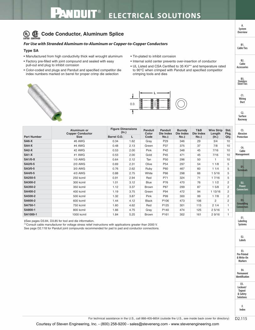
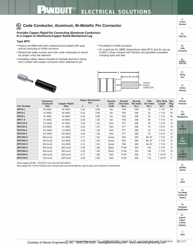
Code Conductor, One-Hole, Short Barrel with Window Lug
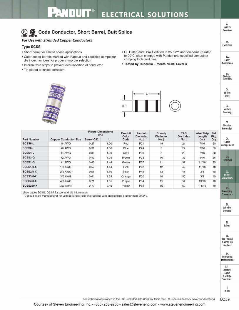
• Short barrel for limited space applications
• Color-coded barrels marked with Panduit and specified competitordie index numbers for proper crimp die selection
• Inspection window to visually assure full conductor insertion
• Tin-plated to inhibit corrosion
• UL Listed and CSA Certified to 35 KV** and temperature rated to90°C when crimped with Panduit and specified competitorcrimping tools and dies
• Tested by Telcordia – meets NEBS Level 3
• American Bureau of Shipping approved
Type LCAS
For Use with Stranded Copper Conductors
W
L
INSPECTIONWINDOW
T
B
‡See pages D3.56, D3.57 for tool and die information.**Consult cable manufacturer for voltage stress relief instructions with applications greater than 2000 V.
Courtesy of Steven Engineering, Inc. - (800) 258-9200 - [email protected] - www.stevenengineering.com
D2.8
ELECTRICAL SOLUTIONS
Prime items appear in BOLD.
B2.Cable
Accessories
C1.Wiring
Duct
C3.Abrasion
Protection
C4.Cable
Management
D1.Terminals
D2.Power
Connectors
E1.LabelingSystems
E2.Labels
E3.Pre-Printed & Write-On
Markers
F.Index
B3.StainlessSteel Ties
C2.Surface
Raceway
E5.Lockout/Tagout
& SafetySolutions
B1.Cable Ties
A.System
Overview
D3.GroundingConnectors
E4.Permanent
Identification
‡See pages D3.56, D3.57 for tool and die information.**Consult cable manufacturer for voltage stress relief instructions with applications greater than 2000 V.
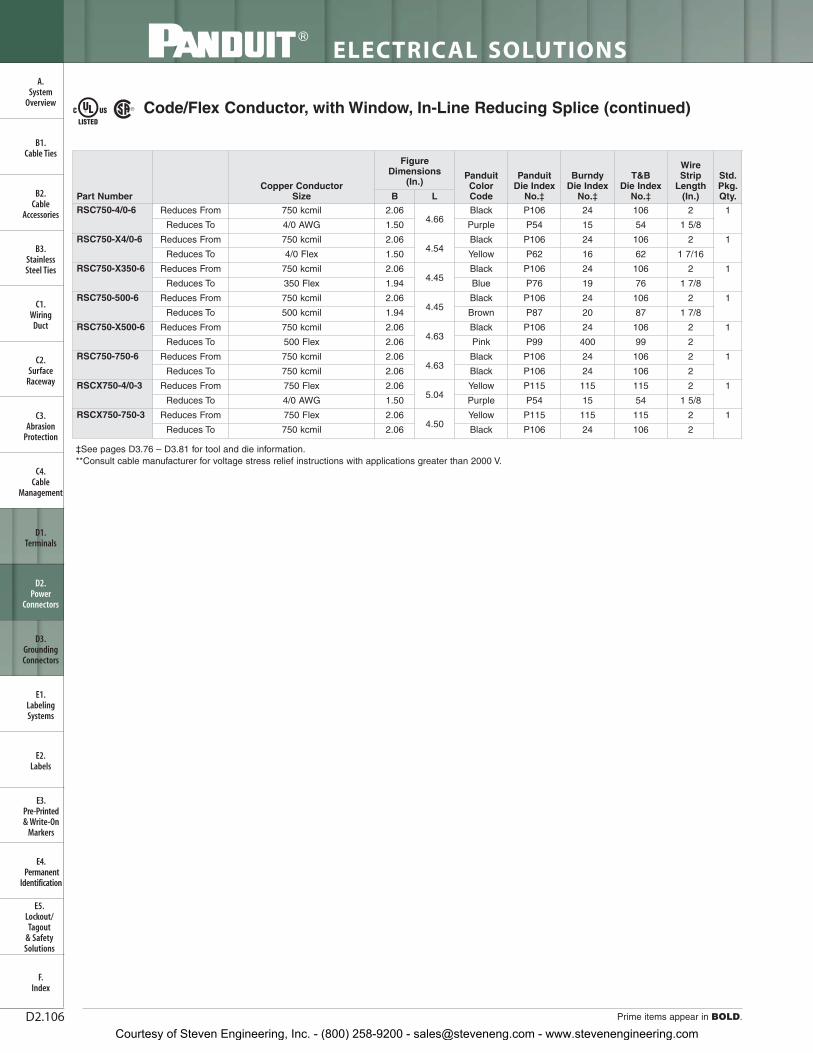
Code Conductor, One-Hole, Short Barrel with Window Lug (continued)
Courtesy of Steven Engineering, Inc. - (800) 258-9200 - [email protected] - www.stevenengineering.com
D2.9For technical assistance in the U.S., call 866-405-6654 (outside the U.S., see inside back cover for directory)
ELECTRICAL SOLUTIONS
B2.Cable
Accessories
C1.Wiring
Duct
C3.Abrasion
Protection
C4.Cable
Management
D1.Terminals
D2.Power
Connectors
E1.LabelingSystems
E2.Labels
E3.Pre-Printed & Write-On
Markers
F.Index
B3.StainlessSteel Ties
C2.Surface
Raceway
E5.Lockout/Tagout
& SafetySolutions
B1.Cable Ties
A.System
Overview
D3.GroundingConnectors
E4.Permanent
Identification
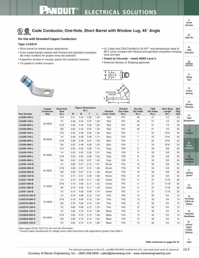
Code Conductor, One-Hole, Short Barrel with Window Lug, 45° Angle
• Short barrel for limited space applications
• Color-coded barrels marked with Panduit and specified competitordie index numbers for proper crimp die selection
• Inspection window to visually assure full conductor insertion
• Tin-plated to inhibit corrosion
• UL Listed and CSA Certified to 35 KV** and temperature rated to90°C when crimped with Panduit and specified competitor crimpingtools and dies
• Tested by Telcordia – meets NEBS Level 3
• American Bureau of Shipping approved
For Use with Stranded Copper Conductors
Type LCAS-H
W
T
L
INSPECTIONWINDOW
B
45˚
‡See pages D3.56, D3.57 for tool and die information.**Consult cable manufacturer for voltage stress relief instructions with applications greater than 2000 V.
Courtesy of Steven Engineering, Inc. - (800) 258-9200 - [email protected] - www.stevenengineering.com
D2.10
ELECTRICAL SOLUTIONS
Prime items appear in BOLD.
B2.Cable
Accessories
C1.Wiring
Duct
C3.Abrasion
Protection
C4.Cable
Management
D1.Terminals
D2.Power
Connectors
E1.LabelingSystems
E2.Labels
E3.Pre-Printed & Write-On
Markers
F.Index
B3.StainlessSteel Ties
C2.Surface
Raceway
E5.Lockout/Tagout
& SafetySolutions
B1.Cable Ties
A.System
Overview
D3.GroundingConnectors
E4.Permanent
Identification
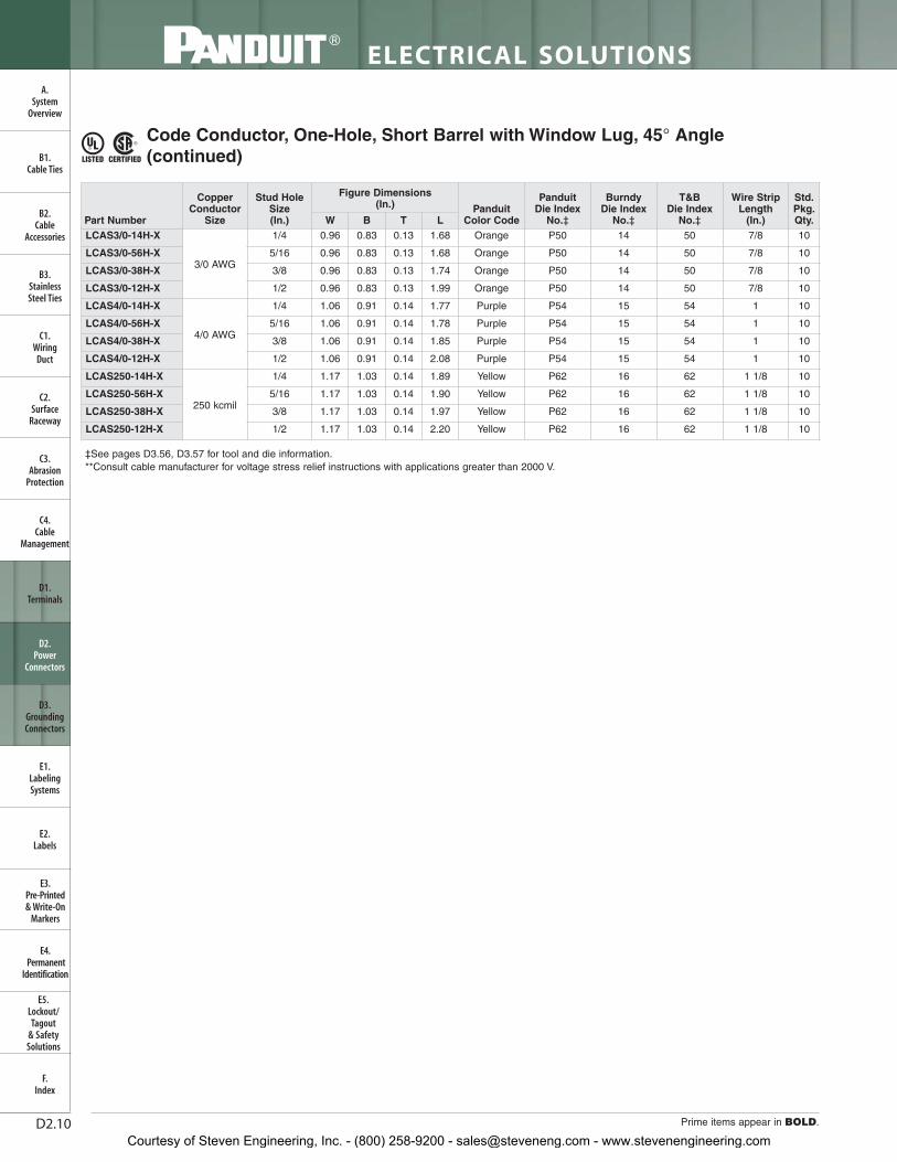
‡See pages D3.56, D3.57 for tool and die information.**Consult cable manufacturer for voltage stress relief instructions with applications greater than 2000 V.
Code Conductor, One-Hole, Short Barrel with Window Lug, 45° Angle(continued)
Courtesy of Steven Engineering, Inc. - (800) 258-9200 - [email protected] - www.stevenengineering.com
D2.11For technical assistance in the U.S., call 866-405-6654 (outside the U.S., see inside back cover for directory)
ELECTRICAL SOLUTIONS
B2.Cable
Accessories
C1.Wiring
Duct
C3.Abrasion
Protection
C4.Cable
Management
D1.Terminals
D2.Power
Connectors
E1.LabelingSystems
E2.Labels
E3.Pre-Printed & Write-On
Markers
F.Index
B3.StainlessSteel Ties
C2.Surface
Raceway
E5.Lockout/Tagout
& SafetySolutions
B1.Cable Ties
A.System
Overview
D3.GroundingConnectors
E4.Permanent
Identification
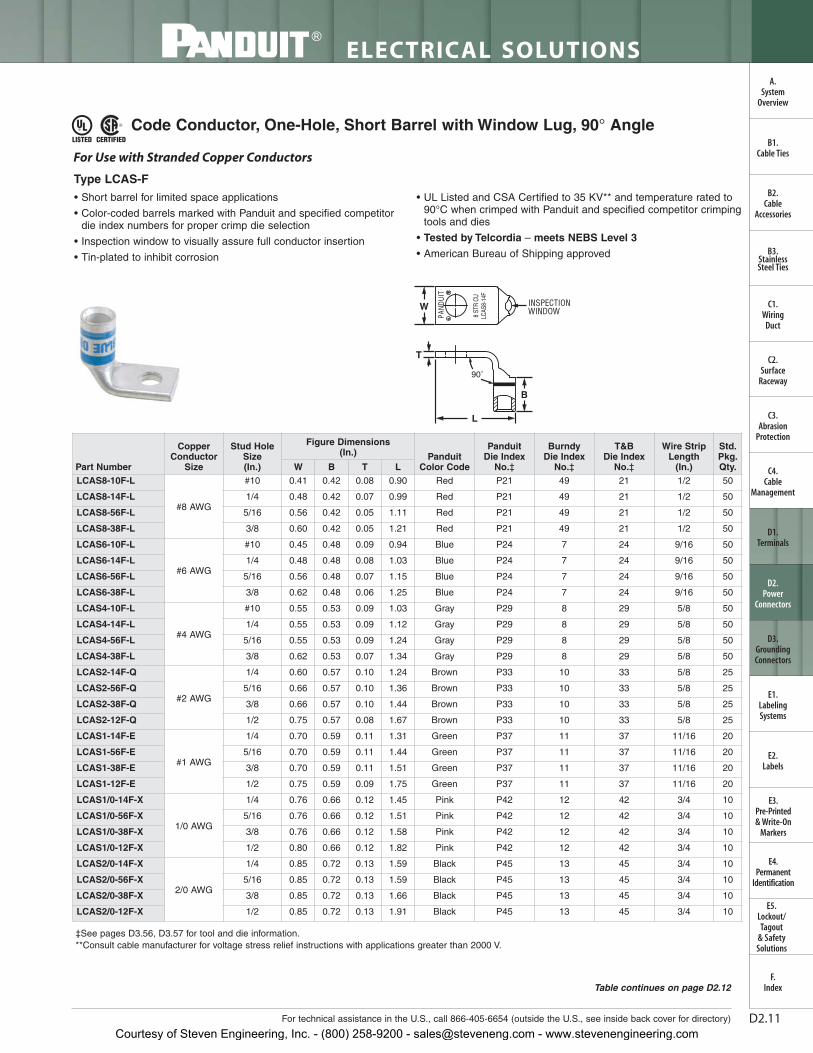
Code Conductor, One-Hole, Short Barrel with Window Lug, 90° Angle
• Short barrel for limited space applications
• Color-coded barrels marked with Panduit and specified competitordie index numbers for proper crimp die selection
• Inspection window to visually assure full conductor insertion
• Tin-plated to inhibit corrosion
• UL Listed and CSA Certified to 35 KV** and temperature rated to90°C when crimped with Panduit and specified competitor crimpingtools and dies
• Tested by Telcordia – meets NEBS Level 3
• American Bureau of Shipping approved
For Use with Stranded Copper Conductors
Type LCAS-F
W INSPECTIONWINDOW
T
L
90˚
B
‡See pages D3.56, D3.57 for tool and die information.**Consult cable manufacturer for voltage stress relief instructions with applications greater than 2000 V.
Courtesy of Steven Engineering, Inc. - (800) 258-9200 - [email protected] - www.stevenengineering.com
D2.12
ELECTRICAL SOLUTIONS
Prime items appear in BOLD.
B2.Cable
Accessories
C1.Wiring
Duct
C3.Abrasion
Protection
C4.Cable
Management
D1.Terminals
D2.Power
Connectors
E1.LabelingSystems
E2.Labels
E3.Pre-Printed & Write-On
Markers
F.Index
B3.StainlessSteel Ties
C2.Surface
Raceway
E5.Lockout/Tagout
& SafetySolutions
B1.Cable Ties
A.System
Overview
D3.GroundingConnectors
E4.Permanent
Identification
‡See pages D3.56, D3.57 for tool and die information.**Consult cable manufacturer for voltage stress relief instructions with applications greater than 2000 V.
Code Conductor, One-Hole, Short Barrel with Window Lug, 90° Angle(continued)
Courtesy of Steven Engineering, Inc. - (800) 258-9200 - [email protected] - www.stevenengineering.com
D2.13For technical assistance in the U.S., call 866-405-6654 (outside the U.S., see inside back cover for directory)
ELECTRICAL SOLUTIONS
B2.Cable
Accessories
C1.Wiring
Duct
C3.Abrasion
Protection
C4.Cable
Management
D1.Terminals
D2.Power
Connectors
E1.LabelingSystems
E2.Labels
E3.Pre-Printed & Write-On
Markers
F.Index
B3.StainlessSteel Ties
C2.Surface
Raceway
E5.Lockout/Tagout
& SafetySolutions
B1.Cable Ties
A.System
Overview
D3.GroundingConnectors
E4.Permanent
Identification
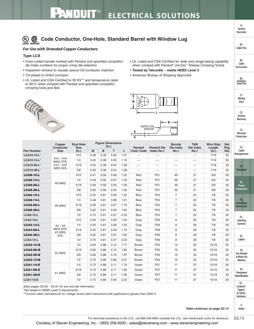
Code Conductor, One-Hole, Standard Barrel with Window Lug
• Color-coded barrels marked with Panduit and specified competitordie index numbers for proper crimp die selection
• Inspection window to visually assure full conductor insertion
• Tin-plated to inhibit corrosion
• UL Listed and CSA Certified to 35 KV** and temperature rated to 90°C when crimped with Panduit and specified competitorcrimping tools and dies
• UL Listed and CSA Certified for wide wire range-taking capabilitywhen crimped with Panduit® Uni-Die ™ Dieless Crimping Tools‡
• Tested by Telcordia – meets NEBS Level 3
• American Bureau of Shipping Approved
For Use with Stranded Copper Conductors
Type LCA
W
T
INSPECTIONWINDOW
L
B
‡See pages D3.58 – D3.61 for tool and die information.*Not tested to NEBS Level 3 requirements.**Consult cable manufacturer for voltage stress relief instructions with applications greater than 2000 V.
Courtesy of Steven Engineering, Inc. - (800) 258-9200 - [email protected] - www.stevenengineering.com
D2.14
ELECTRICAL SOLUTIONS
Prime items appear in BOLD.
B2.Cable
Accessories
C1.Wiring
Duct
C3.Abrasion
Protection
C4.Cable
Management
D1.Terminals
D2.Power
Connectors
E1.LabelingSystems
E2.Labels
E3.Pre-Printed & Write-On
Markers
F.Index
B3.StainlessSteel Ties
C2.Surface
Raceway
E5.Lockout/Tagout
& SafetySolutions
B1.Cable Ties
A.System
Overview
D3.GroundingConnectors
E4.Permanent
Identification‡See pages D3.58 – D3.61 for tool and die information.*Not tested to NEBS Level 3 requirements.**Consult cable manufacturer for voltage stress relief instructions with applications greater than 2000 V.
Code Conductor, One-Hole, Standard Barrel with Window Lug (continued)
Courtesy of Steven Engineering, Inc. - (800) 258-9200 - [email protected] - www.stevenengineering.com
D2.15For technical assistance in the U.S., call 866-405-6654 (outside the U.S., see inside back cover for directory)
ELECTRICAL SOLUTIONS
B2.Cable
Accessories
C1.Wiring
Duct
C3.Abrasion
Protection
C4.Cable
Management
D1.Terminals
D2.Power
Connectors
E1.LabelingSystems
E2.Labels
E3.Pre-Printed & Write-On
Markers
F.Index
B3.StainlessSteel Ties
C2.Surface
Raceway
E5.Lockout/Tagout
& SafetySolutions
B1.Cable Ties
A.System
Overview
D3.GroundingConnectors
E4.Permanent
Identification
Code Conductor, One-Hole, Standard Barrel with Window Lug, 45° Angle
• Color-coded barrels marked with Panduit and specified competitordie index numbers for proper crimp die selection
• Inspection window to visually assure full conductor insertion
• Tin-plated to inhibit corrosion
• UL Listed and CSA Certified to 35 KV** and temperature rated to90°C when crimped with Panduit and specified competitor crimpingtools and dies
• UL Listed and CSA Certified for wide wire range-taking capabilitywhen crimped with Panduit ® Uni-Die™ Dieless Crimping Tools‡
• Tested by Telcordia – meets NEBS Level 3
• American Bureau of Shipping approved
‡See pages D3.58 – D3.61 for tool and die information.*Not tested to NEBS Level 3 requirements.**Consult cable manufacturer for voltage stress relief instructions with applications greater than 2000 V.
Courtesy of Steven Engineering, Inc. - (800) 258-9200 - [email protected] - www.stevenengineering.com
D2.16
ELECTRICAL SOLUTIONS
Prime items appear in BOLD.
B2.Cable
Accessories
C1.Wiring
Duct
C3.Abrasion
Protection
C4.Cable
Management
D1.Terminals
D2.Power
Connectors
E1.LabelingSystems
E2.Labels
E3.Pre-Printed & Write-On
Markers
F.Index
B3.StainlessSteel Ties
C2.Surface
Raceway
E5.Lockout/Tagout
& SafetySolutions
B1.Cable Ties
A.System
Overview
D3.GroundingConnectors
E4.Permanent
Identification
‡See pages D3.58 – D3.61 for tool and die information.*Not tested to NEBS Level 3 requirements.**Consult cable manufacturer for voltage stress relief instructions with applications greater than 2000 V.
Code Conductor, One-Hole, Standard Barrel with Window Lug,45° Angle (continued)
Courtesy of Steven Engineering, Inc. - (800) 258-9200 - [email protected] - www.stevenengineering.com
D2.17For technical assistance in the U.S., call 866-405-6654 (outside the U.S., see inside back cover for directory)
ELECTRICAL SOLUTIONS
B2.Cable
Accessories
C1.Wiring
Duct
C3.Abrasion
Protection
C4.Cable
Management
D1.Terminals
D2.Power
Connectors
E1.LabelingSystems
E2.Labels
E3.Pre-Printed & Write-On
Markers
F.Index
B3.StainlessSteel Ties
C2.Surface
Raceway
E5.Lockout/Tagout
& SafetySolutions
B1.Cable Ties
A.System
Overview
D3.GroundingConnectors
E4.Permanent
Identification
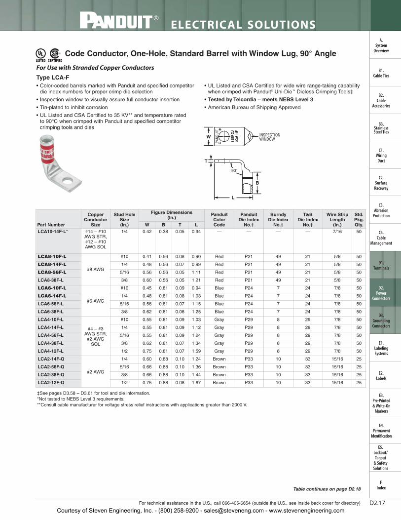
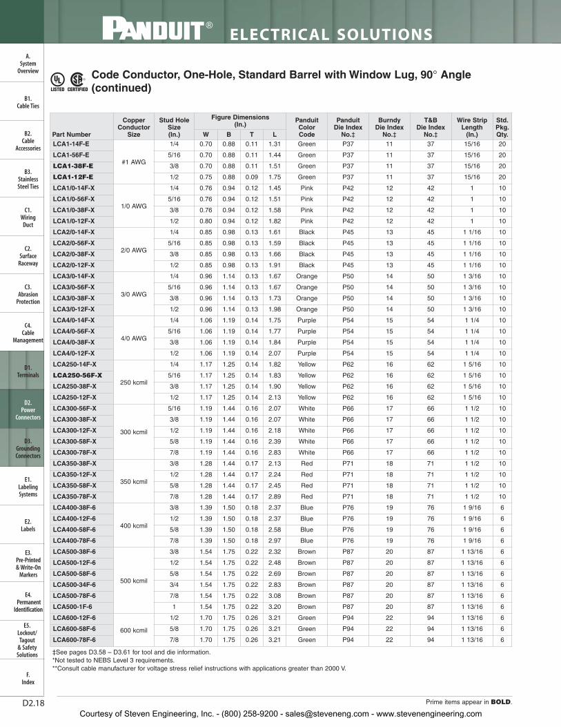
Code Conductor, One-Hole, Standard Barrel with Window Lug, 90° Angle
• Color-coded barrels marked with Panduit and specified competitordie index numbers for proper crimp die selection
• Inspection window to visually assure full conductor insertion
• Tin-plated to inhibit corrosion
• UL Listed and CSA Certified to 35 KV** and temperature rated to 90°C when crimped with Panduit and specified competitorcrimping tools and dies
• UL Listed and CSA Certified for wide wire range-taking capabilitywhen crimped with Panduit® Uni-Die ™ Dieless Crimping Tools‡
• Tested by Telcordia – meets NEBS Level 3
• American Bureau of Shipping Approved
‡See pages D3.58 – D3.61 for tool and die information.*Not tested to NEBS Level 3 requirements.**Consult cable manufacturer for voltage stress relief instructions with applications greater than 2000 V.
Courtesy of Steven Engineering, Inc. - (800) 258-9200 - [email protected] - www.stevenengineering.com
D2.18
ELECTRICAL SOLUTIONS
Prime items appear in BOLD.
B2.Cable
Accessories
C1.Wiring
Duct
C3.Abrasion
Protection
C4.Cable
Management
D1.Terminals
D2.Power
Connectors
E1.LabelingSystems
E2.Labels
E3.Pre-Printed & Write-On
Markers
F.Index
B3.StainlessSteel Ties
C2.Surface
Raceway
E5.Lockout/Tagout
& SafetySolutions
B1.Cable Ties
A.System
Overview
D3.GroundingConnectors
E4.Permanent
Identification
‡See pages D3.58 – D3.61 for tool and die information.*Not tested to NEBS Level 3 requirements.**Consult cable manufacturer for voltage stress relief instructions with applications greater than 2000 V.
Code Conductor, One-Hole, Standard Barrel with Window Lug, 90° Angle(continued)
Courtesy of Steven Engineering, Inc. - (800) 258-9200 - [email protected] - www.stevenengineering.com
D2.19For technical assistance in the U.S., call 866-405-6654 (outside the U.S., see inside back cover for directory)
ELECTRICAL SOLUTIONS
B2.Cable
Accessories
C1.Wiring
Duct
C3.Abrasion
Protection
C4.Cable
Management
D1.Terminals
D2.Power
Connectors
E1.LabelingSystems
E2.Labels
E3.Pre-Printed & Write-On
Markers
F.Index
B3.StainlessSteel Ties
C2.Surface
Raceway
E5.Lockout/Tagout
& SafetySolutions
B1.Cable Ties
A.System
Overview
D3.GroundingConnectors
E4.Permanent
Identification
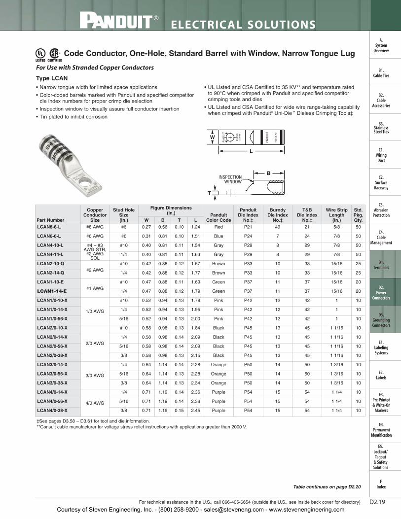
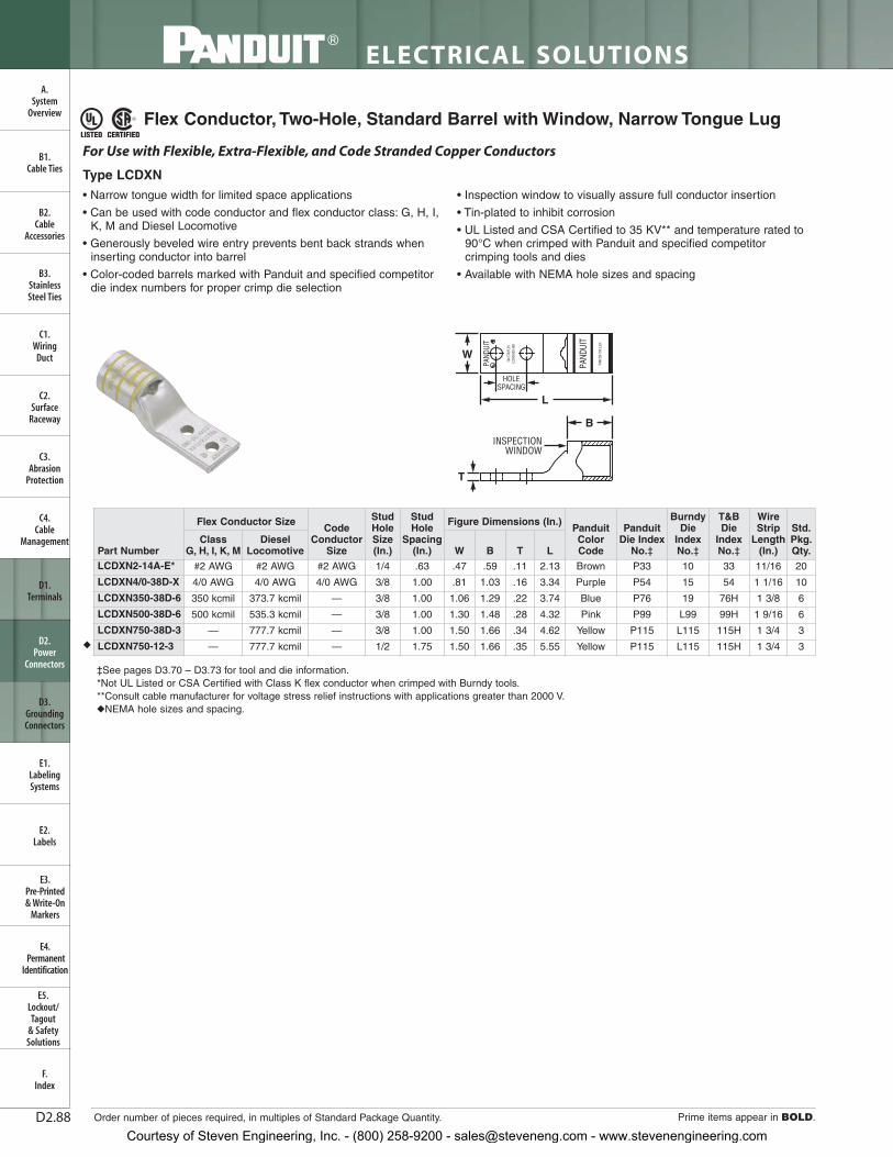
Code Conductor, One-Hole, Standard Barrel with Window, Narrow Tongue Lug
• Narrow tongue width for limited space applications
• Color-coded barrels marked with Panduit and specified competitordie index numbers for proper crimp die selection
• Inspection window to visually assure full conductor insertion
• Tin-plated to inhibit corrosion
• UL Listed and CSA Certified to 35 KV** and temperature rated to 90°C when crimped with Panduit and specified competitorcrimping tools and dies
• UL Listed and CSA Certified for wide wire range-taking capabilitywhen crimped with Panduit® Uni-Die ™ Dieless Crimping Tools‡
W
T
INSPECTIONWINDOW
L
B
For Use with Stranded Copper Conductors
Type LCAN
‡See pages D3.58 – D3.61 for tool and die information.**Consult cable manufacturer for voltage stress relief instructions with applications greater than 2000 V.
Courtesy of Steven Engineering, Inc. - (800) 258-9200 - [email protected] - www.stevenengineering.com
D2.20
ELECTRICAL SOLUTIONS
Prime items appear in BOLD.
B2.Cable
Accessories
C1.Wiring
Duct
C3.Abrasion
Protection
C4.Cable
Management
D1.Terminals
D2.Power
Connectors
E1.LabelingSystems
E2.Labels
E3.Pre-Printed & Write-On
Markers
F.Index
B3.StainlessSteel Ties
C2.Surface
Raceway
E5.Lockout/Tagout
& SafetySolutions
B1.Cable Ties
A.System
Overview
D3.GroundingConnectors
E4.Permanent
Identification
‡See pages D3.58 – D3.61 for tool and die information.**Consult cable manufacturer for voltage stress relief instructions with applications greater than 2000 V.
Code Conductor, One-Hole, Standard Barrel with Window,Narrow Tongue Lug (continued)
Courtesy of Steven Engineering, Inc. - (800) 258-9200 - [email protected] - www.stevenengineering.com
D2.21For technical assistance in the U.S., call 866-405-6654 (outside the U.S., see inside back cover for directory)
ELECTRICAL SOLUTIONS
B2.Cable
Accessories
C1.Wiring
Duct
C3.Abrasion
Protection
C4.Cable
Management
D1.Terminals
D2.Power
Connectors
E1.LabelingSystems
E2.Labels
E3.Pre-Printed & Write-On
Markers
F.Index
B3.StainlessSteel Ties
C2.Surface
Raceway
E5.Lockout/Tagout
& SafetySolutions
B1.Cable Ties
A.System
Overview
D3.GroundingConnectors
E4.Permanent
Identification
‡See pages D3.58 – D3.61 for tool and die information.**Consult cable manufacturer for voltage stress relief instructions with applications greater than 2000 V.
• Color-coded barrels marked with Panduit and specified competitordie index numbers for proper crimp die selection
• Inspection window to visually assure full conductor insertion
• Tin-plated to inhibit corrosion
• UL Recognized and CSA Certified to 35 KV** and temperaturerated to 90°C when crimped with Panduit and specified competitorcrimping tools and dies
W
INSPECTIONWINDOW
L
B
T
For Use with Stranded Copper Conductors
Type LCA-00
Code Conductor, Short Blank Tongue, Standard Barrel with Window Lug
Courtesy of Steven Engineering, Inc. - (800) 258-9200 - [email protected] - www.stevenengineering.com
D2.22
ELECTRICAL SOLUTIONS
Order number of pieces required, in multiples of Standard Package Quantity.
B2.Cable
Accessories
C1.Wiring
Duct
C3.Abrasion
Protection
C4.Cable
Management
D1.Terminals
D2.Power
Connectors
E1.LabelingSystems
E2.Labels
E3.Pre-Printed & Write-On
Markers
F.Index
B3.StainlessSteel Ties
C2.Surface
Raceway
E5.Lockout/Tagout
& SafetySolutions
B1.Cable Ties
A.System
Overview
D3.GroundingConnectors
E4.Permanent
Identification
Prime items appear in BOLD.
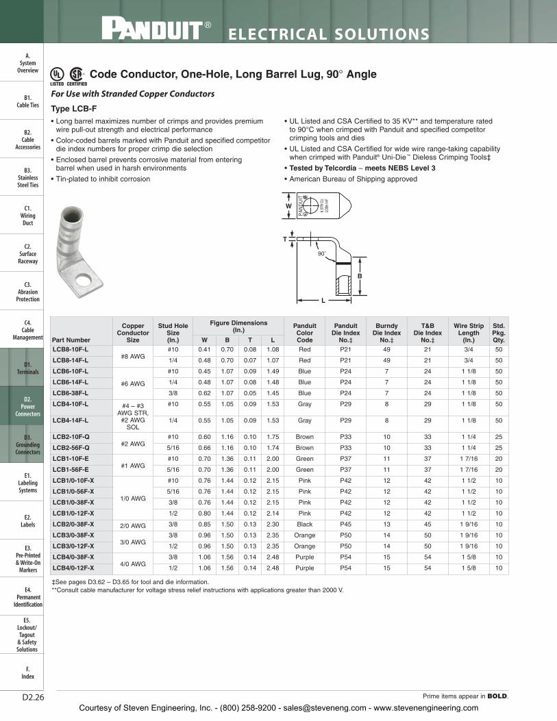
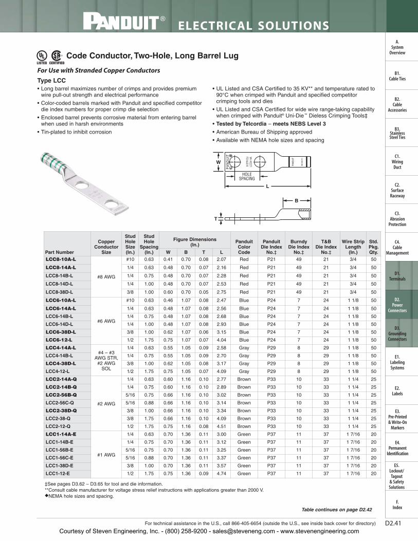
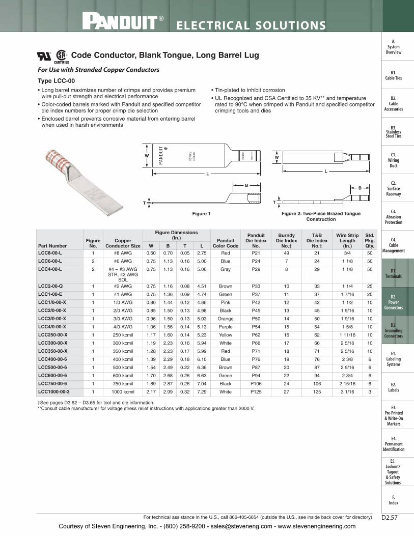
Code Conductor, One-Hole, Long Barrel Lug
• Long barrel maximizes number of crimps and provides premiumwire pull-out strength and electrical performance
• Color-coded barrels marked with Panduit and specified competitordie index numbers for proper crimp die selection
• Enclosed barrel prevents corrosive material from entering barrelwhen used in harsh environments
• Tin-plated to inhibit corrosion
• UL Listed and CSA Certified to 35 KV** and temperature rated to90°C when crimped with Panduit and specified competitorcrimping tools and dies
• UL Listed and CSA Certified for wide wire range-taking capabilitywhen crimped with Panduit ® Uni-Die ™ Dieless Crimping Tools‡
• Tested by Telcordia – meets NEBS Level 3
• American Bureau of Shipping Approved
L
B
W
T
For Use with Stranded Copper Conductors
Type LCB
‡See pages D3.62 – D3.65 for tool and die information.**Consult cable manufacturer for voltage stress relief instructions with applications greater than 2000 V.
Courtesy of Steven Engineering, Inc. - (800) 258-9200 - [email protected] - www.stevenengineering.com
LTBW
Std.Pkg.Qty.
Wire StripLength
(In.)
T&B Die Index
No.‡
Burndy Die Index
No.‡
Panduit Die Index
No.‡
PanduitColor Code
Figure Dimensions (In.)
Stud HoleSize(In.)
CopperConductor
SizePart Number
D2.23For technical assistance in the U.S., call 866-405-6654 (outside the U.S., see inside back cover for directory)
ELECTRICAL SOLUTIONS
B2.Cable
Accessories
C1.Wiring
Duct
C3.Abrasion
Protection
C4.Cable
Management
D1.Terminals
D2.Power
Connectors
E1.LabelingSystems
E2.Labels
E3.Pre-Printed & Write-On
Markers
F.Index
B3.StainlessSteel Ties
C2.Surface
Raceway
E5.Lockout/Tagout
& SafetySolutions
B1.Cable Ties
A.System
Overview
D3.GroundingConnectors
E4.Permanent
Identification
‡See pages D3.62 – D3.65 for tool and die information.**Consult cable manufacturer for voltage stress relief instructions with applications greater than 2000 V.
Code Conductor, One-Hole, Long Barrel Lug (continued)
Courtesy of Steven Engineering, Inc. - (800) 258-9200 - [email protected] - www.stevenengineering.com
D2.24
ELECTRICAL SOLUTIONS
Prime items appear in BOLD.
B2.Cable
Accessories
C1.Wiring
Duct
C3.Abrasion
Protection
C4.Cable
Management
D1.Terminals
D2.Power
Connectors
E1.LabelingSystems
E2.Labels
E3.Pre-Printed & Write-On
Markers
F.Index
B3.StainlessSteel Ties
C2.Surface
Raceway
E5.Lockout/Tagout
& SafetySolutions
B1.Cable Ties
A.System
Overview
D3.GroundingConnectors
E4.Permanent
Identification
Code Conductor, One-Hole, Long Barrel Lug, 45° Angle
‡See pages D3.62 – D3.65 for tool and die information.**Consult cable manufacturer for voltage stress relief instructions with applications greater than 2000 V.
• Long barrel maximizes number of crimps and provides premiumwire pull-out strength and electrical performance
• Color-coded barrels marked with Panduit and specified competitordie index numbers for proper crimp die selection
• Enclosed barrel prevents corrosive material from entering barrel when used in harsh environments
• Tin-plated to inhibit corrosion
• UL Listed and CSA Certified to 35 KV** and temperature rated to 90°C when crimped with Panduit and specified competitorcrimping tools and dies
• UL Listed and CSA Certified for wide wire range-taking capabilitywhen crimped with Panduit® Uni-Die™ Dieless Crimping Tools‡
Courtesy of Steven Engineering, Inc. - (800) 258-9200 - [email protected] - www.stevenengineering.com
LTBW
Std.Pkg.Qty.
Wire StripLength
(In.)
T&B Die Index
No.‡
Burndy Die Index
No.‡
Panduit Die Index
No.‡Panduit
Color Code
Figure Dimensions (In.)
Stud HoleSize(In.)
CopperConductor
SizePart Number
D2.25For technical assistance in the U.S., call 866-405-6654 (outside the U.S., see inside back cover for directory)
ELECTRICAL SOLUTIONS
B2.Cable
Accessories
C1.Wiring
Duct
C3.Abrasion
Protection
C4.Cable
Management
D1.Terminals
D2.Power
Connectors
E1.LabelingSystems
E2.Labels
E3.Pre-Printed & Write-On
Markers
F.Index
B3.StainlessSteel Ties
C2.Surface
Raceway
E5.Lockout/Tagout
& SafetySolutions
B1.Cable Ties
A.System
Overview
D3.GroundingConnectors
E4.Permanent
Identification
‡See pages D3.62 – D3.65 for tool and die information.**Consult cable manufacturer for voltage stress relief instructions with applications greater than 2000 V.
Code Conductor, One-Hole, Long Barrel Lug, 45° Angle (continued)
Courtesy of Steven Engineering, Inc. - (800) 258-9200 - [email protected] - www.stevenengineering.com
D2.26
ELECTRICAL SOLUTIONS
Prime items appear in BOLD.
B2.Cable
Accessories
C1.Wiring
Duct
C3.Abrasion
Protection
C4.Cable
Management
D1.Terminals
D2.Power
Connectors
E1.LabelingSystems
E2.Labels
E3.Pre-Printed & Write-On
Markers
F.Index
B3.StainlessSteel Ties
C2.Surface
Raceway
E5.Lockout/Tagout
& SafetySolutions
B1.Cable Ties
A.System
Overview
D3.GroundingConnectors
E4.Permanent
Identification
Code Conductor, One-Hole, Long Barrel Lug, 90° Angle
• Long barrel maximizes number of crimps and provides premiumwire pull-out strength and electrical performance
• Color-coded barrels marked with Panduit and specified competitordie index numbers for proper crimp die selection
• Enclosed barrel prevents corrosive material from entering barrel when used in harsh environments
• Tin-plated to inhibit corrosion
• UL Listed and CSA Certified to 35 KV** and temperature rated to 90°C when crimped with Panduit and specified competitorcrimping tools and dies
• UL Listed and CSA Certified for wide wire range-taking capabilitywhen crimped with Panduit® Uni-Die™ Dieless Crimping Tools‡
• Tested by Telcordia – meets NEBS Level 3
• American Bureau of Shipping approved
W
T
B
L
90˚
For Use with Stranded Copper Conductors
Type LCB-F
‡See pages D3.62 – D3.65 for tool and die information.**Consult cable manufacturer for voltage stress relief instructions with applications greater than 2000 V.
Courtesy of Steven Engineering, Inc. - (800) 258-9200 - [email protected] - www.stevenengineering.com
LTBW
Std.Pkg.Qty.
Wire StripLength
(In.)
T&B Die Index
No.‡
Burndy DieIndexNo.‡
Panduit Die Index
No.‡
PanduitColorCode
Figure Dimensions (In.)
Stud HoleSize(In.)
CopperConductor
SizePart Number
D2.27For technical assistance in the U.S., call 866-405-6654 (outside the U.S., see inside back cover for directory)
ELECTRICAL SOLUTIONS
B2.Cable
Accessories
C1.Wiring
Duct
C3.Abrasion
Protection
C4.Cable
Management
D1.Terminals
D2.Power
Connectors
E1.LabelingSystems
E2.Labels
E3.Pre-Printed & Write-On
Markers
F.Index
B3.StainlessSteel Ties
C2.Surface
Raceway
E5.Lockout/Tagout
& SafetySolutions
B1.Cable Ties
A.System
Overview
D3.GroundingConnectors
E4.Permanent
Identification
‡See pages D3.62 – D3.65 for tool and die information.**Consult cable manufacturer for voltage stress relief instructions with applications greater than 2000 V.
Code Conductor, One-Hole, Long Barrel Lug, 90° Angle (continued)
Courtesy of Steven Engineering, Inc. - (800) 258-9200 - [email protected] - www.stevenengineering.com
D2.28
ELECTRICAL SOLUTIONS
Prime items appear in BOLD.
B2.Cable
Accessories
C1.Wiring
Duct
C3.Abrasion
Protection
C4.Cable
Management
D1.Terminals
D2.Power
Connectors
E1.LabelingSystems
E2.Labels
E3.Pre-Printed & Write-On
Markers
F.Index
B3.StainlessSteel Ties
C2.Surface
Raceway
E5.Lockout/Tagout
& SafetySolutions
B1.Cable Ties
A.System
Overview
D3.GroundingConnectors
E4.Permanent
Identification
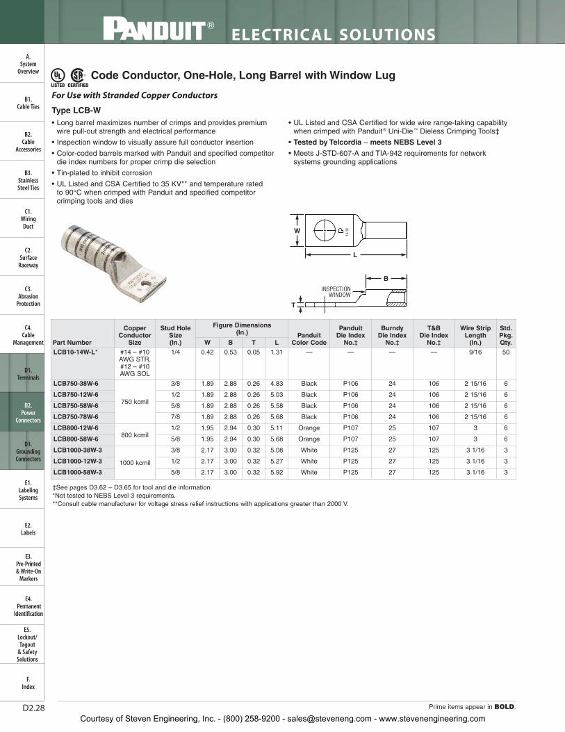
Code Conductor, One-Hole, Long Barrel with Window Lug
‡See pages D3.62 – D3.65 for tool and die information.*Not tested to NEBS Level 3 requirements.**Consult cable manufacturer for voltage stress relief instructions with applications greater than 2000 V.
T
INSPECTIONWINDOW
W
L
B
For Use with Stranded Copper Conductors
Type LCB-W• Long barrel maximizes number of crimps and provides premium
wire pull-out strength and electrical performance
• Inspection window to visually assure full conductor insertion
• Color-coded barrels marked with Panduit and specified competitordie index numbers for proper crimp die selection
• Tin-plated to inhibit corrosion
• UL Listed and CSA Certified to 35 KV** and temperature rated to 90°C when crimped with Panduit and specified competitorcrimping tools and dies
• UL Listed and CSA Certified for wide wire range-taking capabilitywhen crimped with Panduit ® Uni-Die ™ Dieless Crimping Tools‡
• Tested by Telcordia – meets NEBS Level 3
• Meets J-STD-607-A and TIA-942 requirements for networksystems grounding applications
Courtesy of Steven Engineering, Inc. - (800) 258-9200 - [email protected] - www.stevenengineering.com
D2.29For technical assistance in the U.S., call 866-405-6654 (outside the U.S., see inside back cover for directory)
ELECTRICAL SOLUTIONS
B2.Cable
Accessories
C1.Wiring
Duct
C3.Abrasion
Protection
C4.Cable
Management
D1.Terminals
D2.Power
Connectors
E1.LabelingSystems
E2.Labels
E3.Pre-Printed & Write-On
Markers
F.Index
B3.StainlessSteel Ties
C2.Surface
Raceway
E5.Lockout/Tagout
& SafetySolutions
B1.Cable Ties
A.System
Overview
D3.GroundingConnectors
E4.Permanent
Identification
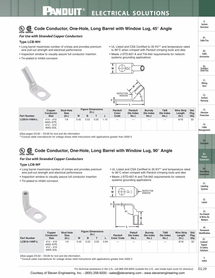
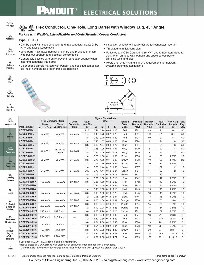
Code Conductor, One-Hole, Long Barrel with Window Lug, 45° Angle
‡See pages D3.62 – D3.65 for tool and die information.**Consult cable manufacturer for voltage stress relief instructions with applications greater than 2000 V.
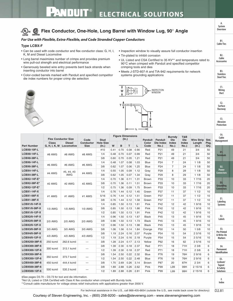
Code Conductor, One-Hole, Long Barrel with Window Lug, 90° Angle
‡See pages D3.62 – D3.65 for tool and die information.**Consult cable manufacturer for voltage stress relief instructions with applications greater than 2000 V.
• Long barrel maximizes number of crimps and provides premiumwire pull-out strength and electrical performance
• Inspection window to visually assure full conductor insertion
• Tin-plated to inhibit corrosion
• UL Listed and CSA Certified to 35 KV** and temperature rated to 90°C when crimped with Panduit crimping tools and dies
• Meets J-STD-607-A and TIA-942 requirements for networksystems grounding applications
W
T
INSPECTIONWINDOW 45˚
L
B
For Use with Stranded Copper Conductors
Type LCB-WH
• Long barrel maximizes number of crimps and provides premiumwire pull-out strength and electrical performance
• Inspection window to visually assure full conductor insertion
• Tin-plated to inhibit corrosion
• UL Listed and CSA Certified to 35 KV** and temperature rated to 90°C when crimped with Panduit crimping tools and dies
• Meets J-STD-607-A and TIA-942 requirements for networksystems grounding applications
W INSPECTIONWINDOW
T
L
B
90˚
For Use with Stranded Copper Conductors
Type LCB-WF
Part Number
CopperConductor
Size
Stud HoleSize(In.)
Figure Dimensions (In.)
PanduitColorCode
PanduitDie Index
No.‡
BurndyDie Index
No.‡
T&BDie Index
No.‡
Wire StripLength
(In.)
Std.Pkg.Qty.W B T L
LCB10-14WH-L #14 – #10AWG STR,#12 – #10AWG SOL
1/4 0.42 0.53 0.05 1.15 — — — — 9/16 50
Part Number
CopperConductor
Size
Stud HoleSize(In.)
Figure Dimensions (In.) Panduit
Color Code
Paduit Die Index
No.‡
BurndyDie Index
No.‡
T&BDie Index
No.‡
Wire StripLength
(In.)
Std.Pkg.Qty.W B T L
LCB10-14WF-L #14 – #10AWG STR,#12 – #10AWG SOL
1/4 0.42 0.53 0.05 0.94 — — — — 9/16 50
Courtesy of Steven Engineering, Inc. - (800) 258-9200 - [email protected] - www.stevenengineering.com
D2.30
ELECTRICAL SOLUTIONS
Prime items appear in BOLD.
B2.Cable
Accessories
C1.Wiring
Duct
C3.Abrasion
Protection
C4.Cable
Management
D1.Terminals
D2.Power
Connectors
E1.LabelingSystems
E2.Labels
E3.Pre-Printed & Write-On
Markers
F.Index
B3.StainlessSteel Ties
C2.Surface
Raceway
E5.Lockout/Tagout
& SafetySolutions
B1.Cable Ties
A.System
Overview
D3.GroundingConnectors
E4.Permanent
Identification
Code Conductor, One-Hole, Long Barrel with Corona Relief Taper Lug
‡See pages D3.66, D3.67 for tool and die information.**Consult cable manufacturer for voltage stress relief instructions with applications greater than 2000 V.
CORONARELIEFTAPER
L
W
B
T
• Externally chamfered barrel end inhibits Corona effect when used in high voltage applications
• Long barrel maximizes number of crimps and provides premiumwire pull-out strength and electrical performance
• Color-coded barrels marked with Panduit and specified competitordie index numbers for proper crimp die selection
• Enclosed barrel prevents corrosive material from entering barrelwhen used in harsh environments
• Tin-plated to inhibit corrosion
• UL Listed and CSA Certified to 35 KV** and temperature rated to 90°C when crimped with Panduit and specified competitorcrimping tools and dies
To Facilitate Use with Stranded Copper Conductors in Applications of 5000 V or More
Courtesy of Steven Engineering, Inc. - (800) 258-9200 - [email protected] - www.stevenengineering.com
D2.31For technical assistance in the U.S., call 866-405-6654 (outside the U.S., see inside back cover for directory)
ELECTRICAL SOLUTIONS
B2.Cable
Accessories
C1.Wiring
Duct
C3.Abrasion
Protection
C4.Cable
Management
D1.Terminals
D2.Power
Connectors
E1.LabelingSystems
E2.Labels
E3.Pre-Printed & Write-On
Markers
F.Index
B3.StainlessSteel Ties
C2.Surface
Raceway
E5.Lockout/Tagout
& SafetySolutions
B1.Cable Ties
A.System
Overview
D3.GroundingConnectors
E4.Permanent
Identification
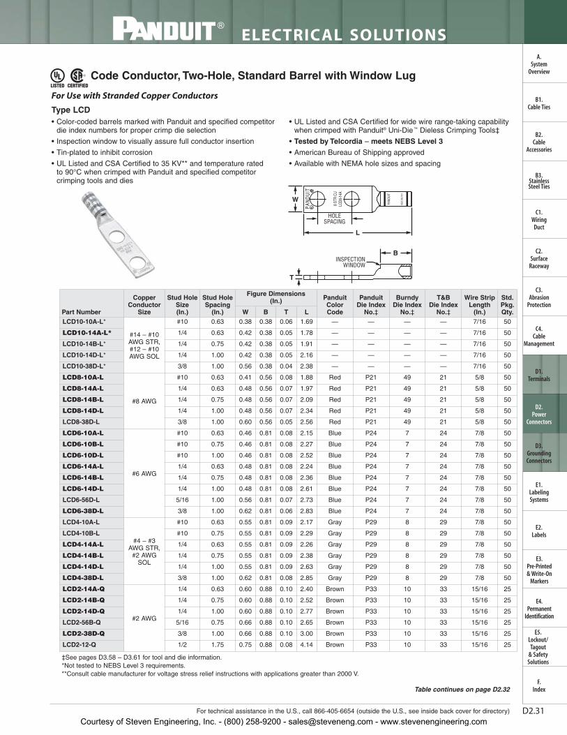
Code Conductor, Two-Hole, Standard Barrel with Window Lug
• Color-coded barrels marked with Panduit and specified competitordie index numbers for proper crimp die selection
• Inspection window to visually assure full conductor insertion
• Tin-plated to inhibit corrosion
• UL Listed and CSA Certified to 35 KV** and temperature rated to 90°C when crimped with Panduit and specified competitorcrimping tools and dies
• UL Listed and CSA Certified for wide wire range-taking capabilitywhen crimped with Panduit® Uni-Die ™ Dieless Crimping Tools‡
• Tested by Telcordia – meets NEBS Level 3
• American Bureau of Shipping approved
• Available with NEMA hole sizes and spacing
W
HOLESPACING
L
T
INSPECTIONWINDOW
B
For Use with Stranded Copper Conductors
Type LCD
‡See pages D3.58 – D3.61 for tool and die information.*Not tested to NEBS Level 3 requirements.**Consult cable manufacturer for voltage stress relief instructions with applications greater than 2000 V.
Courtesy of Steven Engineering, Inc. - (800) 258-9200 - [email protected] - www.stevenengineering.com
D2.32
ELECTRICAL SOLUTIONS
Prime items appear in BOLD.
B2.Cable
Accessories
C1.Wiring
Duct
C3.Abrasion
Protection
C4.Cable
Management
D1.Terminals
D2.Power
Connectors
E1.LabelingSystems
E2.Labels
E3.Pre-Printed & Write-On
Markers
F.Index
B3.StainlessSteel Ties
C2.Surface
Raceway
E5.Lockout/Tagout
& SafetySolutions
B1.Cable Ties
A.System
Overview
D3.GroundingConnectors
E4.Permanent
Identification‡See pages D3.58 – D3.61 for tool and die information.**Consult cable manufacturer for voltage stress relief instructions with applications greater than 2000 V.◆NEMA hole sizes and spacing.
Code Conductor, Two-Hole, Standard Barrel with Window Lug (continued)
Courtesy of Steven Engineering, Inc. - (800) 258-9200 - [email protected] - www.stevenengineering.com
D2.33For technical assistance in the U.S., call 866-405-6654 (outside the U.S., see inside back cover for directory)
ELECTRICAL SOLUTIONS
B2.Cable
Accessories
C1.Wiring
Duct
C3.Abrasion
Protection
C4.Cable
Management
D1.Terminals
D2.Power
Connectors
E1.LabelingSystems
E2.Labels
E3.Pre-Printed & Write-On
Markers
F.Index
B3.StainlessSteel Ties
C2.Surface
Raceway
E5.Lockout/Tagout
& SafetySolutions
B1.Cable Ties
A.System
Overview
D3.GroundingConnectors
E4.Permanent
Identification
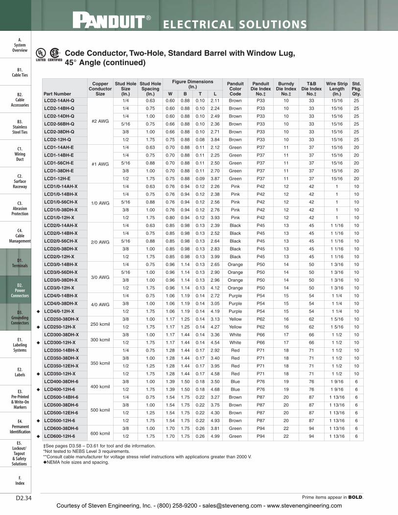
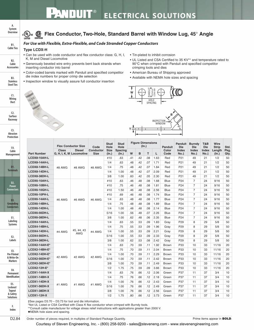
• Color-coded barrels marked with Panduit and specified competitordie index numbers for proper crimp die selection
• Inspection window to visually assure full conductor insertion
• Tin-plated to inhibit corrosion
• UL Listed and CSA Certified to 35 KV** and temperature rated to90°C when crimped with Panduit and specified competitorcrimping tools and dies
• UL Listed and CSA Certified for wide wire range-taking capabilitywhen crimped with Panduit® Uni-Die™ Dieless Crimping Tools‡
• Tested by Telcordia – meets NEBS Level 3
• American Bureau of Shipping approved
• Available with NEMA hole sizes and spacing
45˚
HOLESPACING
W
INSPECTIONWINDOW
T
L
B
For Use with Stranded Copper Conductors
Type LCD-H
Table continues on page D2.34
Code Conductor, Two-Hole, Standard Barrel with Window Lug, 45° Angle
‡See pages D3.58 – D3.61 for tool and die information.*Not tested to NEBS Level 3 requirements.**Consult cable manufacturer for voltage stress relief instructions with applications greater than 2000 V.◆NEMA hole sizes and spacing.
Courtesy of Steven Engineering, Inc. - (800) 258-9200 - [email protected] - www.stevenengineering.com
D2.34
ELECTRICAL SOLUTIONS
Prime items appear in BOLD.
B2.Cable
Accessories
C1.Wiring
Duct
C3.Abrasion
Protection
C4.Cable
Management
D1.Terminals
D2.Power
Connectors
E1.LabelingSystems
E2.Labels
E3.Pre-Printed & Write-On
Markers
F.Index
B3.StainlessSteel Ties
C2.Surface
Raceway
E5.Lockout/Tagout
& SafetySolutions
B1.Cable Ties
A.System
Overview
D3.GroundingConnectors
E4.Permanent
Identification
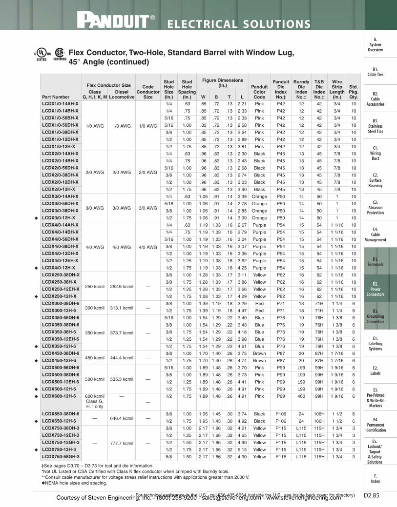
Code Conductor, Two-Hole, Standard Barrel with Window Lug,45° Angle (continued)
‡See pages D3.58 – D3.61 for tool and die information.*Not tested to NEBS Level 3 requirements.**Consult cable manufacturer for voltage stress relief instructions with applications greater than 2000 V.◆NEMA hole sizes and spacing.
Courtesy of Steven Engineering, Inc. - (800) 258-9200 - [email protected] - www.stevenengineering.com
D2.35For technical assistance in the U.S., call 866-405-6654 (outside the U.S., see inside back cover for directory)
ELECTRICAL SOLUTIONS
B2.Cable
Accessories
C1.Wiring
Duct
C3.Abrasion
Protection
C4.Cable
Management
D1.Terminals
D2.Power
Connectors
E1.LabelingSystems
E2.Labels
E3.Pre-Printed & Write-On
Markers
F.Index
B3.StainlessSteel Ties
C2.Surface
Raceway
E5.Lockout/Tagout
& SafetySolutions
B1.Cable Ties
A.System
Overview
D3.GroundingConnectors
E4.Permanent
Identification
Code Conductor, Two-Hole, Standard Barrel with Window Lug, 90° Angle
• Color-coded barrels marked with Panduit and specified competitordie index numbers for proper crimp die selection
• Inspection window to visually assure full conductor insertion
• Tin-plated to inhibit corrosion
• UL Listed and CSA Certified to 35 KV** and temperature rated to90°C when crimped with Panduit and specified competitor crimpingtools and dies
• UL Listed and CSA Certified for wide wire range-taking capabilitywhen crimped with Panduit® Uni-Die ™ Dieless Crimping Tools‡
• Tested by Telcordia – meets NEBS Level 3
• American Bureau of Shipping approved
• Available with NEMA hole sizes and spacing
INSPECTIONWINDOW
HOLESPACING
W
T
B
L
90˚
For Use with Stranded Copper Conductors
Type LCD-F
‡See pages D3.58 – D3.61 for tool and die information.*Not tested to NEBS Level 3 requirements.**Consult cable manufacturer for voltage stress relief instructions with applications greater than 2000 V.
Courtesy of Steven Engineering, Inc. - (800) 258-9200 - [email protected] - www.stevenengineering.com
D2.36
ELECTRICAL SOLUTIONS
Order number of pieces required, in multiples of Standard Package Quantity. Prime items appear in BOLD.
B2.Cable
Accessories
C1.Wiring
Duct
C3.Abrasion
Protection
C4.Cable
Management
D1.Terminals
D2.Power
Connectors
E1.LabelingSystems
E2.Labels
E3.Pre-Printed & Write-On
Markers
F.Index
B3.StainlessSteel Ties
C2.Surface
Raceway
E5.Lockout/Tagout
& SafetySolutions
B1.Cable Ties
A.System
Overview
D3.GroundingConnectors
E4.Permanent
Identification
‡See pages D3.58 – D3.61 for tool and die information.**Consult cable manufacturer for voltage stress relief instructions with applications greater than 2000 V.◆NEMA hole sizes and spacing.
Code Conductor, Two-Hole, Standard Barrel with Window Lug,90° Angle (continued)
Courtesy of Steven Engineering, Inc. - (800) 258-9200 - [email protected] - www.stevenengineering.com
D2.37For technical assistance in the U.S., call 866-405-6654 (outside the U.S., see inside back cover for directory)
ELECTRICAL SOLUTIONS
B2.Cable
Accessories
C1.Wiring
Duct
C3.Abrasion
Protection
C4.Cable
Management
D1.Terminals
D2.Power
Connectors
E1.LabelingSystems
E2.Labels
E3.Pre-Printed & Write-On
Markers
F.Index
B3.StainlessSteel Ties
C2.Surface
Raceway
E5.Lockout/Tagout
& SafetySolutions
B1.Cable Ties
A.System
Overview
D3.GroundingConnectors
E4.Permanent
Identification
Code Conductor, Two-Hole, Standard Barrel with Window, Narrow Tongue Lug
‡See pages D3.58 – D3.61 for tool and die information.**Consult cable manufacturer for voltage stress relief instructions with applications greater than 2000 V.
• Narrow tongue width for limited space applications
• Color-coded barrels marked with Panduit and specified competitordie index numbers for proper crimp die selection
• Inspection window to visually assure full conductor insertion
• Tin-plated to inhibit corrosion
• UL Listed and CSA Certified to 35 KV** and temperature rated to90°C when crimped with Panduit and specified competitorcrimping tools and dies
• UL Listed and CSA Certified for wide wire range-taking capabilitywhen crimped with Panduit® Uni-Die ™ Dieless Crimping Tools‡
Courtesy of Steven Engineering, Inc. - (800) 258-9200 - [email protected] - www.stevenengineering.com
D2.38
ELECTRICAL SOLUTIONS
Prime items appear in BOLD.
B2.Cable
Accessories
C1.Wiring
Duct
C3.Abrasion
Protection
C4.Cable
Management
D1.Terminals
D2.Power
Connectors
E1.LabelingSystems
E2.Labels
E3.Pre-Printed & Write-On
Markers
F.Index
B3.StainlessSteel Ties
C2.Surface
Raceway
E5.Lockout/Tagout
& SafetySolutions
B1.Cable Ties
A.System
Overview
D3.GroundingConnectors
E4.Permanent
Identification
Code Conductor, Two-Hole, Standard Barrel with Window, Narrow Tongue Lug, 45°
‡See pages D3.58 – D3.61 for tool and die information.**Consult cable manufacturer for voltage stress relief instructions with applications greater than 2000 V.
HOLESPACING
W
T
L
INSPECTIONWINDOW
45˚
B
• Narrow tongue width for limited space applications
• Color-coded barrels marked with Panduit and specified competitordie index numbers for proper crimp die selection
• Inspection window to visually assure full conductor insertion
• Tin-plated to inhibit corrosion
• UL Listed and CSA Certified to 35 KV** and temperature rated to90°C when crimped with Panduit and specified competitorcrimping tools and dies
• UL Listed and CSA Certified for wide wire range-taking capabilitywhen crimped with Panduit® Uni-Die ™ Dieless Crimping Tools‡
Courtesy of Steven Engineering, Inc. - (800) 258-9200 - [email protected] - www.stevenengineering.com
D2.39For technical assistance in the U.S., call 866-405-6654 (outside the U.S., see inside back cover for directory)
ELECTRICAL SOLUTIONS
B2.Cable
Accessories
C1.Wiring
Duct
C3.Abrasion
Protection
C4.Cable
Management
D1.Terminals
D2.Power
Connectors
E1.LabelingSystems
E2.Labels
E3.Pre-Printed & Write-On
Markers
F.Index
B3.StainlessSteel Ties
C2.Surface
Raceway
E5.Lockout/Tagout
& SafetySolutions
B1.Cable Ties
A.System
Overview
D3.GroundingConnectors
E4.Permanent
Identification
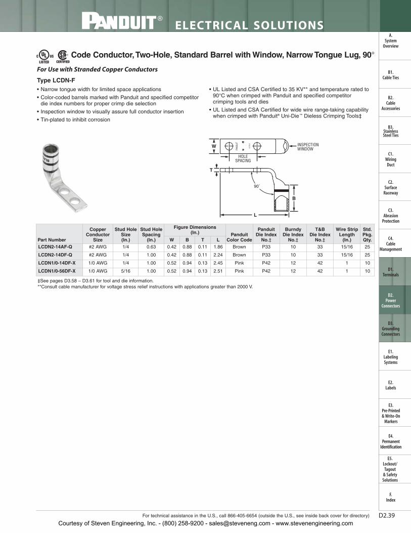
Code Conductor,Two-Hole, Standard Barrel with Window, Narrow Tongue Lug, 90°
‡See pages D3.58 – D3.61 for tool and die information.**Consult cable manufacturer for voltage stress relief instructions with applications greater than 2000 V.
• Narrow tongue width for limited space applications
• Color-coded barrels marked with Panduit and specified competitordie index numbers for proper crimp die selection
• Inspection window to visually assure full conductor insertion
• Tin-plated to inhibit corrosion
• UL Listed and CSA Certified to 35 KV** and temperature rated to90°C when crimped with Panduit and specified competitorcrimping tools and dies
• UL Listed and CSA Certified for wide wire range-taking capabilitywhen crimped with Panduit® Uni-Die ™ Dieless Crimping Tools‡
Courtesy of Steven Engineering, Inc. - (800) 258-9200 - [email protected] - www.stevenengineering.com
D2.40
ELECTRICAL SOLUTIONS
Prime items appear in BOLD.
B2.Cable
Accessories
C1.Wiring
Duct
C3.Abrasion
Protection
C4.Cable
Management
D1.Terminals
D2.Power
Connectors
E1.LabelingSystems
E2.Labels
E3.Pre-Printed & Write-On
Markers
F.Index
B3.StainlessSteel Ties
C2.Surface
Raceway
E5.Lockout/Tagout
& SafetySolutions
B1.Cable Ties
A.System
Overview
D3.GroundingConnectors
E4.Permanent
Identification
Code Conductor, Long Blank Tongue, Standard Barrel with Window Lug
‡See pages D3.58 – D3.61 for tool and die information.**Consult cable manufacturer for voltage stress relief instructions with applications greater than 2000 V.
• Color-coded barrels marked with Panduit and specified competitordie index numbers for proper crimp die selection
• Inspection window to visually assure full conductor insertion
• Tin-plated to inhibit corrosion
• UL Recognized and CSA Certified to 35 KV** and temperaturerated to 90°C when crimped with Panduit and specified competitorcrimping tools and dies
Courtesy of Steven Engineering, Inc. - (800) 258-9200 - [email protected] - www.stevenengineering.com
D2.41For technical assistance in the U.S., call 866-405-6654 (outside the U.S., see inside back cover for directory)
ELECTRICAL SOLUTIONS
B2.Cable
Accessories
C1.Wiring
Duct
C3.Abrasion
Protection
C4.Cable
Management
D1.Terminals
D2.Power
Connectors
E1.LabelingSystems
E2.Labels
E3.Pre-Printed & Write-On
Markers
F.Index
B3.StainlessSteel Ties
C2.Surface
Raceway
E5.Lockout/Tagout
& SafetySolutions
B1.Cable Ties
A.System
Overview
D3.GroundingConnectors
E4.Permanent
Identification
Code Conductor, Two-Hole, Long Barrel Lug
‡See pages D3.62 – D3.65 for tool and die information.**Consult cable manufacturer for voltage stress relief instructions with applications greater than 2000 V.◆NEMA hole sizes and spacing.
• Long barrel maximizes number of crimps and provides premiumwire pull-out strength and electrical performance
• Color-coded barrels marked with Panduit and specified competitordie index numbers for proper crimp die selection
• Enclosed barrel prevents corrosive material from entering barrelwhen used in harsh environments
• Tin-plated to inhibit corrosion
• UL Listed and CSA Certified to 35 KV** and temperature rated to90°C when crimped with Panduit and specified competitorcrimping tools and dies
• UL Listed and CSA Certified for wide wire range-taking capabilitywhen crimped with Panduit® Uni-Die ™ Dieless Crimping Tools‡
Courtesy of Steven Engineering, Inc. - (800) 258-9200 - [email protected] - www.stevenengineering.com
D2.42
ELECTRICAL SOLUTIONS
Prime items appear in BOLD.
B2.Cable
Accessories
C1.Wiring
Duct
C3.Abrasion
Protection
C4.Cable
Management
D1.Terminals
D2.Power
Connectors
E1.LabelingSystems
E2.Labels
E3.Pre-Printed & Write-On
Markers
F.Index
B3.StainlessSteel Ties
C2.Surface
Raceway
E5.Lockout/Tagout
& SafetySolutions
B1.Cable Ties
A.System
Overview
D3.GroundingConnectors
E4.Permanent
Identification
‡See pages D3.62 – D3.65 for tool and die information.**Consult cable manufacturer for voltage stress relief instructions with applications greater than 2000 V.◆NEMA hole sizes and spacing.
Code Conductor, Two-Hole, Long Barrel Lug (continued)
Courtesy of Steven Engineering, Inc. - (800) 258-9200 - [email protected] - www.stevenengineering.com
D2.43For technical assistance in the U.S., call 866-405-6654 (outside the U.S., see inside back cover for directory)
ELECTRICAL SOLUTIONS
B2.Cable
Accessories
C1.Wiring
Duct
C3.Abrasion
Protection
C4.Cable
Management
D1.Terminals
D2.Power
Connectors
E1.LabelingSystems
E2.Labels
E3.Pre-Printed & Write-On
Markers
F.Index
B3.StainlessSteel Ties
C2.Surface
Raceway
E5.Lockout/Tagout
& SafetySolutions
B1.Cable Ties
A.System
Overview
D3.GroundingConnectors
E4.Permanent
Identification
Code Conductor, Two-Hole, Long Barrel Lug, 45° Angle
• Long barrel maximizes number of crimps and provides premiumwire pull-out strength and electrical performance
• Color-coded barrels marked with Panduit and specified competitordie index numbers for proper crimp die selection
• Enclosed barrel prevents corrosive material from entering barrelwhen used in harsh environments
• Tin-plated to inhibit corrosion
• UL Listed and CSA Certified to 35 KV** and temperature rated to90°C when crimped with Panduit and specified competitorcrimping tools and dies
• UL Listed and CSA Certified for wide wire range-taking capabilitywhen crimped with Panduit® Uni-Die ™ Dieless Crimping Tools‡
• Tested by Telcordia – meets NEBS Level 3
• American Bureau of Shipping approved
• Available with NEMA hole sizes and spacing
HOLESPACING
W
T
L
45˚
B
For Use with Stranded Copper Conductors
Type LCC-H
‡See pages D3.62 – D3.65 for tool and die information.**Consult cable manufacturer for voltage stress relief instructions with applications greater than 2000 V.◆NEMA hole sizes and spacing.
Courtesy of Steven Engineering, Inc. - (800) 258-9200 - [email protected] - www.stevenengineering.com
D2.44
ELECTRICAL SOLUTIONS
Prime items appear in BOLD.
B2.Cable
Accessories
C1.Wiring
Duct
C3.Abrasion
Protection
C4.Cable
Management
D1.Terminals
D2.Power
Connectors
E1.LabelingSystems
E2.Labels
E3.Pre-Printed & Write-On
Markers
F.Index
B3.StainlessSteel Ties
C2.Surface
Raceway
E5.Lockout/Tagout
& SafetySolutions
B1.Cable Ties
A.System
Overview
D3.GroundingConnectors
E4.Permanent
Identification
Code Conductor, Two-Hole, Long Barrel Lug, 45° Angle (continued)
‡See pages D3.62 – D3.65 for tool and die information.**Consult cable manufacturer for voltage stress relief instructions with applications greater than 2000 V.◆NEMA hole sizes and spacing.
Courtesy of Steven Engineering, Inc. - (800) 258-9200 - [email protected] - www.stevenengineering.com
D2.45For technical assistance in the U.S., call 866-405-6654 (outside the U.S., see inside back cover for directory)
ELECTRICAL SOLUTIONS
B2.Cable
Accessories
C1.Wiring
Duct
C3.Abrasion
Protection
C4.Cable
Management
D1.Terminals
D2.Power
Connectors
E1.LabelingSystems
E2.Labels
E3.Pre-Printed & Write-On
Markers
F.Index
B3.StainlessSteel Ties
C2.Surface
Raceway
E5.Lockout/Tagout
& SafetySolutions
B1.Cable Ties
A.System
Overview
D3.GroundingConnectors
E4.Permanent
Identification
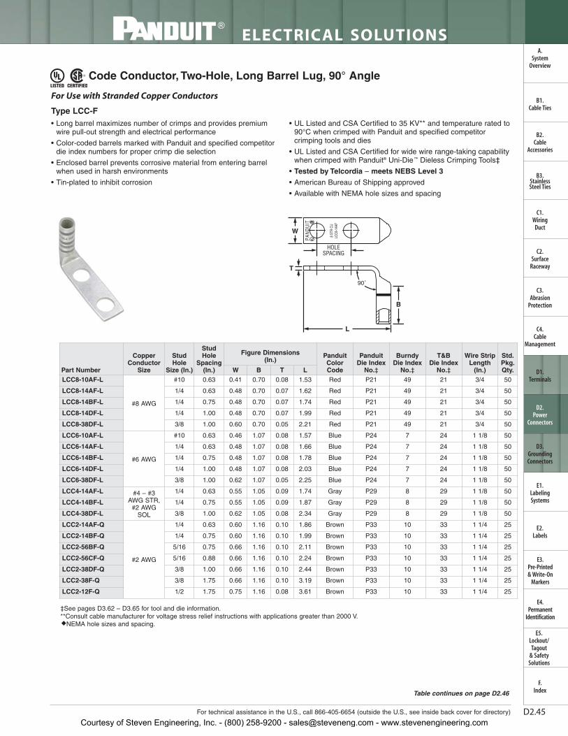
Code Conductor, Two-Hole, Long Barrel Lug, 90° Angle
• Long barrel maximizes number of crimps and provides premiumwire pull-out strength and electrical performance
• Color-coded barrels marked with Panduit and specified competitordie index numbers for proper crimp die selection
• Enclosed barrel prevents corrosive material from entering barrelwhen used in harsh environments
• Tin-plated to inhibit corrosion
• UL Listed and CSA Certified to 35 KV** and temperature rated to90°C when crimped with Panduit and specified competitorcrimping tools and dies
• UL Listed and CSA Certified for wide wire range-taking capabilitywhen crimped with Panduit® Uni-Die ™ Dieless Crimping Tools‡
• Tested by Telcordia – meets NEBS Level 3
• American Bureau of Shipping approved
• Available with NEMA hole sizes and spacing
HOLESPACING
W
L
B
T
90˚
For Use with Stranded Copper Conductors
Type LCC-F
‡See pages D3.62 – D3.65 for tool and die information.**Consult cable manufacturer for voltage stress relief instructions with applications greater than 2000 V.◆NEMA hole sizes and spacing.
Courtesy of Steven Engineering, Inc. - (800) 258-9200 - [email protected] - www.stevenengineering.com
D2.46
ELECTRICAL SOLUTIONS
Prime items appear in BOLD.
B2.Cable
Accessories
C1.Wiring
Duct
C3.Abrasion
Protection
C4.Cable
Management
D1.Terminals
D2.Power
Connectors
E1.LabelingSystems
E2.Labels
E3.Pre-Printed & Write-On
Markers
F.Index
B3.StainlessSteel Ties
C2.Surface
Raceway
E5.Lockout/Tagout
& SafetySolutions
B1.Cable Ties
A.System
Overview
D3.GroundingConnectors
E4.Permanent
Identification
Code Conductor, Two-Hole, Long Barrel Lug, 90° Angle (continued)
‡See pages D3.62 – D3.65 for tool and die information.**Consult cable manufacturer for voltage stress relief instructions with applications greater than 2000 V.◆NEMA hole sizes and spacing.
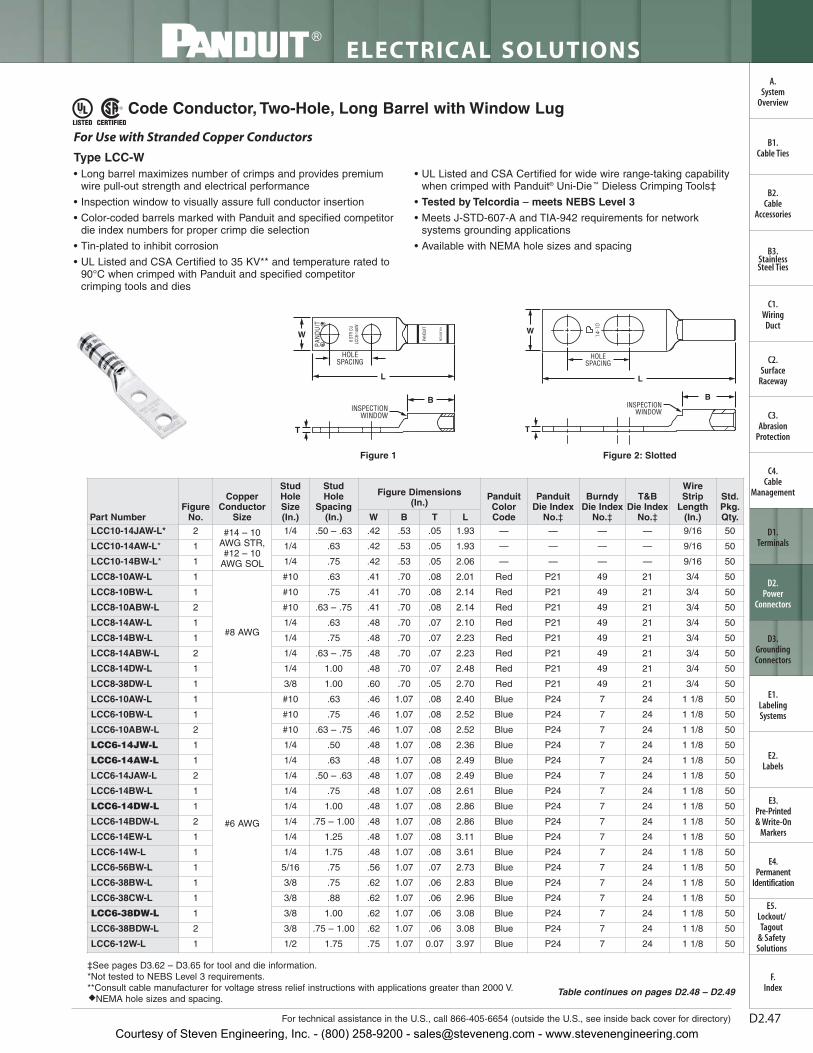
• Long barrel maximizes number of crimps and provides premiumwire pull-out strength and electrical performance
• Inspection window to visually assure full conductor insertion
• Color-coded barrels marked with Panduit and specified competitordie index numbers for proper crimp die selection
• Tin-plated to inhibit corrosion
• UL Listed and CSA Certified to 35 KV** and temperature rated to90°C when crimped with Panduit and specified competitorcrimping tools and dies
• UL Listed and CSA Certified for wide wire range-taking capabilitywhen crimped with Panduit® Uni-Die ™ Dieless Crimping Tools‡
• Tested by Telcordia – meets NEBS Level 3
• Meets J-STD-607-A and TIA-942 requirements for networksystems grounding applications
• Available with NEMA hole sizes and spacing
W
HOLESPACING
T
L
INSPECTIONWINDOW
B
For Use with Stranded Copper Conductors
Type LCC-W
‡See pages D3.62 – D3.65 for tool and die information.*Not tested to NEBS Level 3 requirements.**Consult cable manufacturer for voltage stress relief instructions with applications greater than 2000 V.◆NEMA hole sizes and spacing.
W
HOLESPACING
L
BINSPECTION
WINDOW
T
Figure 1 Figure 2: Slotted
Table continues on pages D2.48 – D2.49
Courtesy of Steven Engineering, Inc. - (800) 258-9200 - [email protected] - www.stevenengineering.com
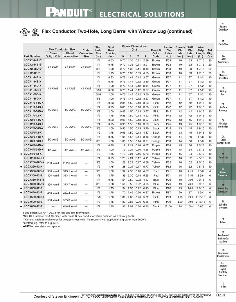
Code Conductor, Two-Hole, Long Barrel with Window Lug (continued)
‡See pages D3.62 – D3.65 for tool and die information.*Not tested to NEBS Level 3 requirements.**Consult cable manufacturer for voltage stress relief instructions with applications greater than 2000 V.◆NEMA hole sizes and spacing.
Courtesy of Steven Engineering, Inc. - (800) 258-9200 - [email protected] - www.stevenengineering.com
D2.49For technical assistance in the U.S., call 866-405-6654 (outside the U.S., see inside back cover for directory)
‡See pages D3.62 – D3.65 for tool and die information.*Not tested to NEBS Level 3 requirements.**Consult cable manufacturer for voltage stress relief instructions with applications greater than 2000 V.◆NEMA hole sizes and spacing.
Code Conductor, Two-Hole, Long Barrel with Window Lug (continued)
Courtesy of Steven Engineering, Inc. - (800) 258-9200 - [email protected] - www.stevenengineering.com
ELECTRICAL SOLUTIONS
Order number of pieces required, in multiples of Standard Package Quantity. Prime items appear in BOLD.D2.50
B2.Cable
Accessories
C1.Wiring
Duct
C3.Abrasion
Protection
C4.Cable
Management
D1.Terminals
D2.Power
Connectors
E1.LabelingSystems
E2.Labels
E3.Pre-Printed & Write-On
Markers
F.Index
B3.StainlessSteel Ties
C2.Surface
Raceway
E5.Lockout/Tagout
& SafetySolutions
B1.Cable Ties
A.System
Overview
D3.GroundingConnectors
E4.Permanent
Identification
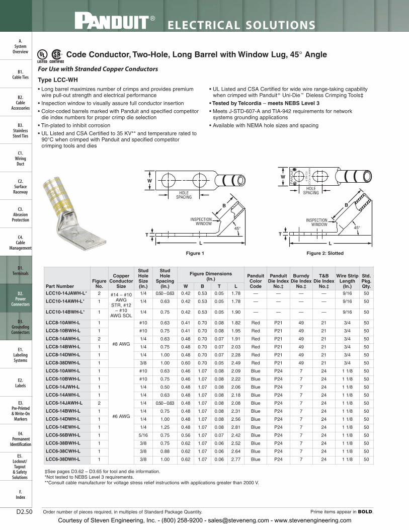
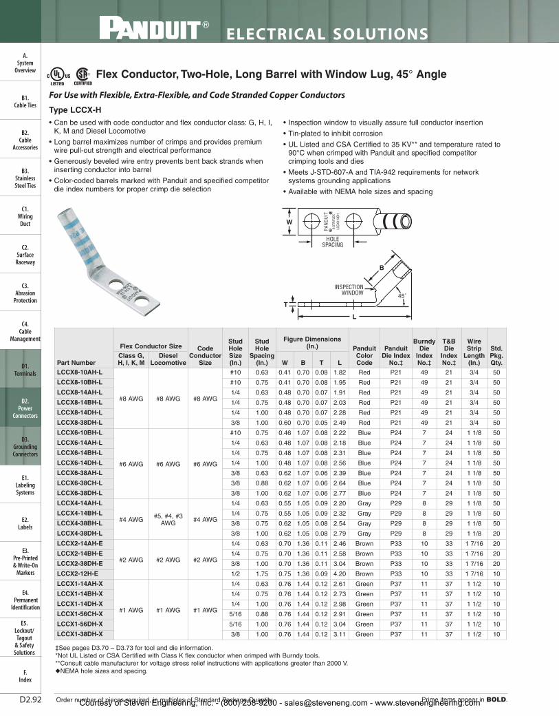
Code Conductor, Two-Hole, Long Barrel with Window Lug, 45° Angle
• Long barrel maximizes number of crimps and provides premiumwire pull-out strength and electrical performance
• Inspection window to visually assure full conductor insertion
• Color-coded barrels marked with Panduit and specified competitordie index numbers for proper crimp die selection
• Tin-plated to inhibit corrosion
• UL Listed and CSA Certified to 35 KV** and temperature rated to90°C when crimped with Panduit and specified competitorcrimping tools and dies
• UL Listed and CSA Certified for wide wire range-taking capabilitywhen crimped with Panduit ® Uni-Die ™ Dieless Crimping Tools‡
• Tested by Telcordia – meets NEBS Level 3
• Meets J-STD-607-A and TIA-942 requirements for networksystems grounding applications
• Available with NEMA hole sizes and spacing
W
HOLESPACING
INSPECTIONWINDOW
L
B
45°
T
For Use with Stranded Copper Conductors
Type LCC-WH
‡See pages D3.62 – D3.65 for tool and die information.*Not tested to NEBS Level 3 requirements.**Consult cable manufacturer for voltage stress relief instructions with applications greater than 2000 V.
Courtesy of Steven Engineering, Inc. - (800) 258-9200 - [email protected] - www.stevenengineering.com
LTBW
Std.Pkg.Qty.
Wire Strip Length
(In.)
T&BDie Index
No.‡
BurndyDie Index
No.‡
Panduit Die Index
No.‡
PanduitColorCode
Figure Dimensions (In.)
StudHole
Spacing (In.)
StudHoleSize(In.)
CopperConductor
SizeFigure
No.Part Number
For technical assistance in the U.S., call 866-405-6654 (outside the U.S., see inside back cover for directory)
ELECTRICAL SOLUTIONS
D2.51
B2.Cable
Accessories
C1.Wiring
Duct
C3.Abrasion
Protection
C4.Cable
Management
D1.Terminals
D2.Power
Connectors
E1.LabelingSystems
E2.Labels
E3.Pre-Printed & Write-On
Markers
F.Index
B3.StainlessSteel Ties
C2.Surface
Raceway
E5.Lockout/Tagout
& SafetySolutions
B1.Cable Ties
D3.GroundingConnectors
E4.Permanent
Identification
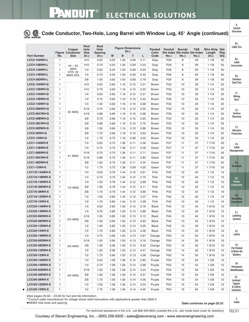
Code Conductor, Two-Hole, Long Barrel with Window Lug, 45° Angle (continued)
‡See pages D3.62 – D3.65 for tool and die information.**Consult cable manufacturer for voltage stress relief instructions with applications greater than 2000 V.◆NEMA hole sizes and spacing. Table continues on page D2.52
Courtesy of Steven Engineering, Inc. - (800) 258-9200 - [email protected] - www.stevenengineering.com
ELECTRICAL SOLUTIONS
Prime items appear in BOLD.D2.52
B2.Cable
Accessories
C1.Wiring
Duct
C3.Abrasion
Protection
C4.Cable
Management
D1.Terminals
D2.Power
Connectors
E1.LabelingSystems
E2.Labels
E3.Pre-Printed & Write-On
Markers
F.Index
B3.StainlessSteel Ties
C2.Surface
Raceway
E5.Lockout/Tagout
& SafetySolutions
B1.Cable Ties
A.System
Overview
D3.GroundingConnectors
E4.Permanent
Identification
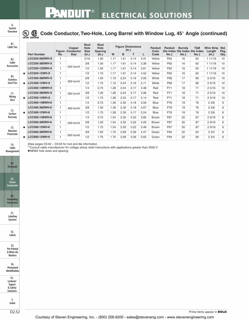
Code Conductor, Two-Hole, Long Barrel with Window Lug, 45° Angle (continued)
‡See pages D3.62 – D3.65 for tool and die information.**Consult cable manufacturer for voltage stress relief instructions with applications greater than 2000 V.◆NEMA hole sizes and spacing.
Courtesy of Steven Engineering, Inc. - (800) 258-9200 - [email protected] - www.stevenengineering.com
For technical assistance in the U.S., call 866-405-6654 (outside the U.S., see inside back cover for directory)
ELECTRICAL SOLUTIONS
D2.53
B2.Cable
Accessories
C1.Wiring
Duct
C3.Abrasion
Protection
C4.Cable
Management
D1.Terminals
D2.Power
Connectors
E1.LabelingSystems
E2.Labels
E3.Pre-Printed & Write-On
Markers
F.Index
B3.StainlessSteel Ties
C2.Surface
Raceway
E5.Lockout/Tagout
& SafetySolutions
B1.Cable Ties
A.System
Overview
D3.GroundingConnectors
E4.Permanent
Identification
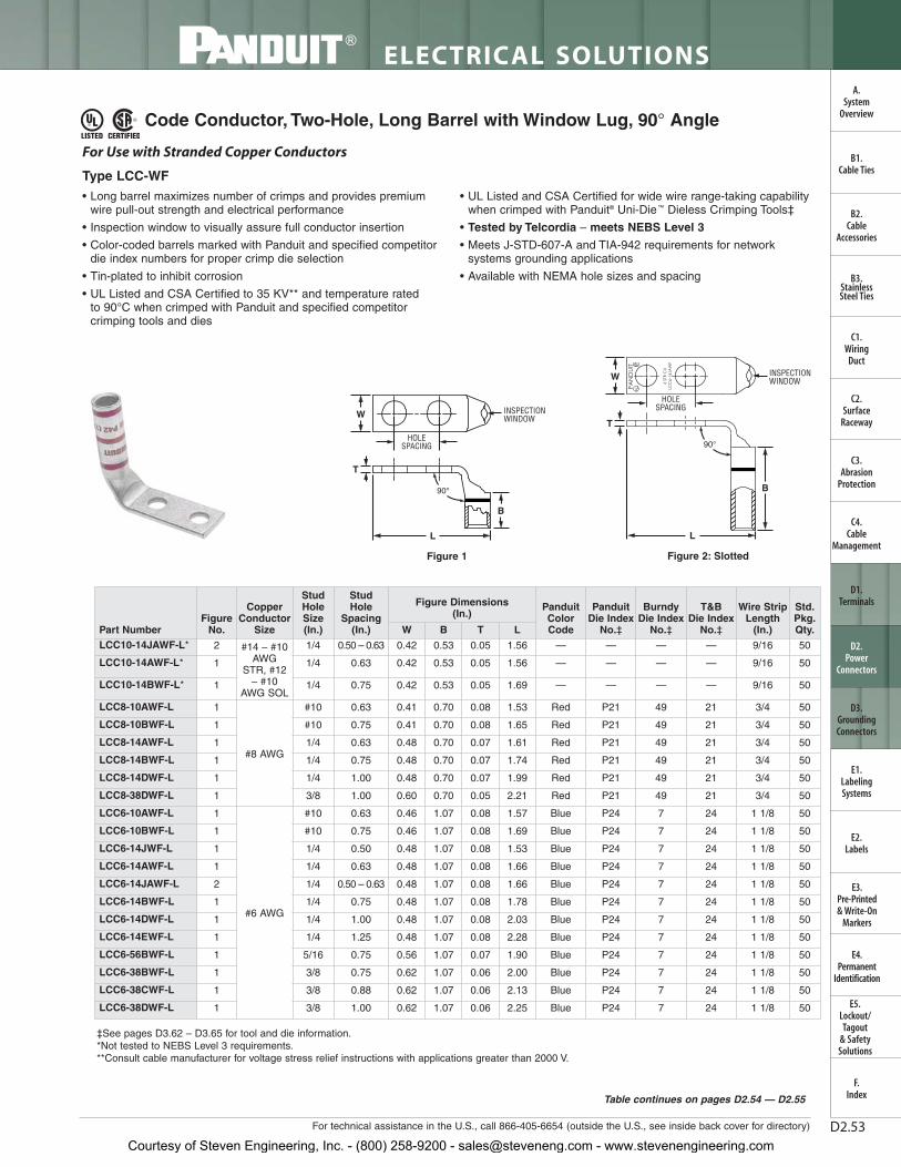
Code Conductor, Two-Hole, Long Barrel with Window Lug, 90° Angle
• Long barrel maximizes number of crimps and provides premiumwire pull-out strength and electrical performance
• Inspection window to visually assure full conductor insertion
• Color-coded barrels marked with Panduit and specified competitordie index numbers for proper crimp die selection
• Tin-plated to inhibit corrosion
• UL Listed and CSA Certified to 35 KV** and temperature rated to 90°C when crimped with Panduit and specified competitorcrimping tools and dies
• UL Listed and CSA Certified for wide wire range-taking capabilitywhen crimped with Panduit® Uni-Die ™ Dieless Crimping Tools‡
• Tested by Telcordia – meets NEBS Level 3
• Meets J-STD-607-A and TIA-942 requirements for networksystems grounding applications
• Available with NEMA hole sizes and spacing
INSPECTIONWINDOWW
HOLESPACING
B
L
90°
T
For Use with Stranded Copper Conductors
Type LCC-WF
B
INSPECTIONWINDOW
HOLESPACING
W
L
90°
T
Figure 1 Figure 2: Slotted
‡See pages D3.62 – D3.65 for tool and die information.*Not tested to NEBS Level 3 requirements.**Consult cable manufacturer for voltage stress relief instructions with applications greater than 2000 V.
Courtesy of Steven Engineering, Inc. - (800) 258-9200 - [email protected] - www.stevenengineering.com
ELECTRICAL SOLUTIONS
Order number of pieces required, in multiples of Standard Package Quantity. Prime items appear in BOLD.D2.54
B2.Cable
Accessories
C1.Wiring
Duct
C3.Abrasion
Protection
C4.Cable
Management
D1.Terminals
D2.Power
Connectors
E1.LabelingSystems
E2.Labels
E3.Pre-Printed & Write-On
Markers
F.Index
B3.StainlessSteel Ties
C2.Surface
Raceway
E5.Lockout/Tagout
& SafetySolutions
B1.Cable Ties
A.System
Overview
D3.GroundingConnectors
E4.Permanent
Identification
Code Conductor, Two-Hole, Long Barrel with Window Lug, 90° Angle (continued)
‡See pages D3.62 – D3.65 for tool and die information.**Consult cable manufacturer for voltage stress relief instructions with applications greater than 2000 V.◆NEMA hole sizes and spacing.
Courtesy of Steven Engineering, Inc. - (800) 258-9200 - [email protected] - www.stevenengineering.com
LTBW
Std.Pkg.Qty.
Wire Strip Length
(In.)
T&BDie Index
No.‡
Burndy Die Index
No.‡
Panduit Die Index
No.‡
Panduit Color Code
Figure Dimensions (In.)
StudHole
Spacing (In.)
Stud Hole Size (In.)
Copper Conductor
SizeFigure
No.Part Number
For technical assistance in the U.S., call 866-405-6654 (outside the U.S., see inside back cover for directory)
ELECTRICAL SOLUTIONS
D2.55
B2.Cable
Accessories
C1.Wiring
Duct
C3.Abrasion
Protection
C4.Cable
Management
D1.Terminals
D2.Power
Connectors
E1.LabelingSystems
E2.Labels
E3.Pre-Printed & Write-On
Markers
F.Index
B3.StainlessSteel Ties
C2.Surface
Raceway
E5.Lockout/Tagout
& SafetySolutions
B1.Cable Ties
A.System
Overview
D3.GroundingConnectors
E4.Permanent
Identification
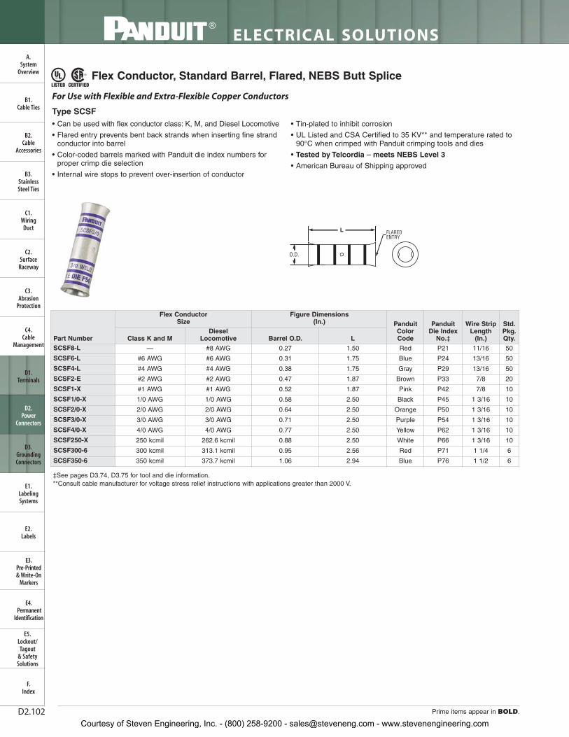
Code Conductor, Two-Hole, Long Barrel with Window, Narrow Tongue Lug
Code Conductor, Two-Hole, Long Barrel with Window Lug, 90° Angle (continued)
‡See pages D3.62 – D3.65 for tool and die information.**Consult cable manufacturer for voltage stress relief instructions with applications greater than 2000 V.◆NEMA hole sizes and spacing.
• Narrow tongue width for limited space applications
• Long barrel maximizes number of crimps and provides premiumwire pull-out strength and electrical performance
• Inspection window to visually assure full conductor insertion
• Color-coded barrels marked with Panduit and specified competitordie index numbers for proper crimp die selection
• Tin-plated to inhibit corrosion
• UL Listed and CSA Certified to 35 KV** and temperature rated to 90°C when crimped with Panduit and specified competitorcrimping tools and dies
• UL Listed and CSA Certified for wide wire range-taking capabilitywhen crimped with Panduit® Uni-Die ™ Dieless Crimping Tools‡
• Tested by Telcordia – meets NEBS Level 3
• Meets J-STD-607-A and TIA-942 requirements for networksystems grounding applications
• Available with NEMA hole sizes and spacing
For Use with Stranded Copper Conductors
Type LCCN-W
HOLESPACING
L
W
INSPECTIONWINDOW
B
T
‡See pages D3.62 – D3.65 for tool and die information.**Consult cable manufacturer for voltage stress relief instructions with applications greater than 2000 V.◆NEMA hole sizes and spacing.
Courtesy of Steven Engineering, Inc. - (800) 258-9200 - [email protected] - www.stevenengineering.com
ELECTRICAL SOLUTIONS
Prime items appear in BOLD.D2.56
B2.Cable
Accessories
C1.Wiring
Duct
C3.Abrasion
Protection
C4.Cable
Management
D1.Terminals
D2.Power
Connectors
E1.LabelingSystems
E2.Labels
E3.Pre-Printed & Write-On
Markers
F.Index
B3.StainlessSteel Ties
C2.Surface
Raceway
E5.Lockout/Tagout
& SafetySolutions
B1.Cable Ties
A.System
Overview
D3.GroundingConnectors
E4.Permanent
Identification
Code Conductor, Two-Hole, Long Barrel with Corona Relief Taper Lug
• Externally chamfered barrel end inhibits Corona effect when usedin high voltage applications
• Long barrel maximizes number of crimps and provides premiumwire pull-out strength and electrical performance
• Color-coded barrels marked with Panduit and specified competitordie index numbers for proper crimp die selection
• Enclosed barrel prevents corrosive material from entering barrelwhen used in harsh environments
• Tin-plated to inhibit corrosion
• UL Listed and CSA Certified to 35 KV** and temperature rated to 90°C when crimped with Panduit and specified competitorcrimping tools and dies
• Available with NEMA hole sizes and spacing
CORONARELIEFTAPER
W
HOLESPACING
L
T
B
To Facilitate Use with Stranded Copper Conductors in Applications of 5000 V or More
Type LCCH
‡See pages D3.66, D3.67 for tool and die information.**Consult cable manufacturer for voltage stress relief instructions with applications greater than 2000 V.◆NEMA hole sizes and spacing.
‡See pages D3.62 – D3.65 for tool and die information.**Consult cable manufacturer for voltage stress relief instructions with applications greater than 2000 V.
Courtesy of Steven Engineering, Inc. - (800) 258-9200 - [email protected] - www.stevenengineering.com
ELECTRICAL SOLUTIONS
Prime items appear in BOLD.D2.58
B2.Cable
Accessories
C1.Wiring
Duct
C3.Abrasion
Protection
C4.Cable
Management
D1.Terminals
D2.Power
Connectors
E1.LabelingSystems
E2.Labels
E3.Pre-Printed & Write-On
Markers
F.Index
B3.StainlessSteel Ties
C2.Surface
Raceway
E5.Lockout/Tagout
& SafetySolutions
B1.Cable Ties
A.System
Overview
D3.GroundingConnectors
E4.Permanent
Identification
Code Conductor, Blank Tongue, Long Barrel with Window Lug
• Long barrel maximizes number of crimps and provides premium wire pull-out strength and electrical performance
• Inspection window to visually assure full conductor insertion
• Color-coded barrels marked with Panduit and specified competitordie index numbers for proper crimp die selection
• Enclosed barrel prevents corrosive material from entering barrel when used in harsh environments
• Tin-plated to inhibit corrosion
• UL Recognized and CSA Certified to 35 KV** and temperaturerated to 90°C when crimped with Panduit and specified competitorcrimping tools and dies
L
W
BINSPECTION
WINDOW
T
For Use with Stranded Copper ConductorsType LCC-00W
‡See pages D3.62 – D3.65 for tool and die information.**Consult cable manufacturer for voltage stress relief instructions with applications greater than 2000 V.
Courtesy of Steven Engineering, Inc. - (800) 258-9200 - [email protected] - www.stevenengineering.com
For technical assistance in the U.S., call 866-405-6654 (outside the U.S., see inside back cover for directory)
ELECTRICAL SOLUTIONS
D2.59
B2.Cable
Accessories
C1.Wiring
Duct
C3.Abrasion
Protection
C4.Cable
Management
D1.Terminals
D2.Power
Connectors
E1.LabelingSystems
E2.Labels
E3.Pre-Printed & Write-On
Markers
F.Index
B3.StainlessSteel Ties
C2.Surface
Raceway
E5.Lockout/Tagout
& SafetySolutions
B1.Cable Ties
A.System
Overview
D3.GroundingConnectors
E4.Permanent
Identification
Code Conductor, Short Barrel, Butt Splice
• Short barrel for limited space applications
• Color-coded barrels marked with Panduit and specified competitordie index numbers for proper crimp die selection
• Internal wire stops to prevent over-insertion of conductor
• Tin-plated to inhibit corrosion
• UL Listed and CSA Certified to 35 KV** and temperature rated to 90°C when crimped with Panduit and specified competitorcrimping tools and dies
• Tested by Telcordia – meets NEBS Level 3
O.D.
L
For Use with Stranded Copper Conductors
Type SCSS
‡See pages D3.56, D3.57 for tool and die information.**Consult cable manufacturer for voltage stress relief instructions with applications greater than 2000 V.
Courtesy of Steven Engineering, Inc. - (800) 258-9200 - [email protected] - www.stevenengineering.com
ELECTRICAL SOLUTIONS
Prime items appear in BOLD.D2.60
B2.Cable
Accessories
C1.Wiring
Duct
C3.Abrasion
Protection
C4.Cable
Management
D1.Terminals
D2.Power
Connectors
E1.LabelingSystems
E2.Labels
E3.Pre-Printed & Write-On
Markers
F.Index
B3.StainlessSteel Ties
C2.Surface
Raceway
E5.Lockout/Tagout
& SafetySolutions
B1.Cable Ties
A.System
Overview
D3.GroundingConnectors
E4.Permanent
Identification
Code Conductor, Standard Barrel, Butt Splice
• Color-coded barrels marked with Panduit and specified competitordie index numbers for proper crimp die selection
• Internal wire stops to prevent over-insertion of conductor
• Tin-plated to inhibit corrosion
• UL Listed and CSA Certified to 35 KV** and temperature rated to 90°C when crimped with Panduit and specified competitorcrimping tools and dies
• UL Listed and CSA Certified for wide wire range-taking capabilitywhen crimped with Panduit® Uni-Die ™ Dieless Crimping Tools‡
• Tested by Telcordia – meets NEBS Level 3
• American Bureau of Shipping approved
For Use with Stranded Copper Conductors
Type SCS
O.D.
L
‡See pages D3.58 – D3.61 for tool and die information.**Consult cable manufacturer for voltage stress relief instructions with applications greater than 2000 V.
Courtesy of Steven Engineering, Inc. - (800) 258-9200 - [email protected] - www.stevenengineering.com
For technical assistance in the U.S., call 866-405-6654 (outside the U.S., see inside back cover for directory)
ELECTRICAL SOLUTIONS
D2.61
B2.Cable
Accessories
C1.Wiring
Duct
C3.Abrasion
Protection
C4.Cable
Management
D1.Terminals
D2.Power
Connectors
E1.LabelingSystems
E2.Labels
E3.Pre-Printed & Write-On
Markers
F.Index
B3.StainlessSteel Ties
C2.Surface
Raceway
E5.Lockout/Tagout
& SafetySolutions
B1.Cable Ties
A.System
Overview
D3.GroundingConnectors
E4.Permanent
Identification
Code Conductor, Long Barrel, Butt Splice
• Long barrel maximizes the number of crimps and providespremium wire pull-out strength and electrical performance
• Color-coded barrels marked with Panduit and specified competitordie index numbers for proper crimp die selection
• Internal wire stops to prevent over-insertion of conductor
• Tin-plated to inhibit corrosion
• UL Listed and CSA Certified to 35 KV** and temperature rated to 90°C when crimped with Panduit and specified competitorcrimping tools and dies
• UL Listed and CSA Certified for wide wire range-taking capabilitywhen crimped with Panduit® Uni-Die ™ Dieless Crimping Tools‡
• Tested by Telcordia – meets NEBS Level 3
For Use with Stranded Copper Conductors
Type SCL
O.D.
L
‡See pages D3.62 – D3.65 for tool and die information.**Consult cable manufacturer for voltage stress relief instructions with applications greater than 2000 V.
Courtesy of Steven Engineering, Inc. - (800) 258-9200 - [email protected] - www.stevenengineering.com
ELECTRICAL SOLUTIONS
Prime items appear in BOLD.D2.62
B2.Cable
Accessories
C1.Wiring
Duct
C3.Abrasion
Protection
C4.Cable
Management
D1.Terminals
D2.Power
Connectors
E1.LabelingSystems
E2.Labels
E3.Pre-Printed & Write-On
Markers
F.Index
B3.StainlessSteel Ties
C2.Surface
Raceway
E5.Lockout/Tagout
& SafetySolutions
B1.Cable Ties
A.System
Overview
D3.GroundingConnectors
E4.Permanent
Identification
Code Conductor, Long Barrel with Corona Relief Taper Splice
• Externally chamfered barrel end inhibits Corona effect when used in high voltage applications
• Color-coded barrels marked with Panduit and specified competitordie index numbers for proper crimp die selection
• Internal wire stops to prevent over-insertion of conductor
• Tin-plated to inhibit corrosion
• UL Listed and CSA Certified to 35 KV** and temperature rated to 90°C when crimped with Panduit and specified competitorcrimping tools and dies
To Facilitate Use with Stranded Copper Conductors in Applications of 5000 V or More
Type SCH
O.D.
L
‡See pages D3.66, D3.67 for tool and die information.**Consult cable manufacturer for voltage stress relief instructions with applications greater than 2000 V.
SCT500-500 500 kcmil 500 kcmil 1.06 1.06 2.50 6.06 Brown P87 Brown P87 3 1/8 2 9/16 1
Courtesy of Steven Engineering, Inc. - (800) 258-9200 - [email protected] - www.stevenengineering.com
ELECTRICAL SOLUTIONS
Prime items appear in BOLD.D2.64
B2.Cable
Accessories
C1.Wiring
Duct
C3.Abrasion
Protection
C4.Cable
Management
D1.Terminals
D2.Power
Connectors
E1.LabelingSystems
E2.Labels
E3.Pre-Printed & Write-On
Markers
F.Index
B3.StainlessSteel Ties
C2.Surface
Raceway
E5.Lockout/Tagout
& SafetySolutions
B1.Cable Ties
A.System
Overview
D3.GroundingConnectors
E4.Permanent
Identification
• Industry recognized color-coding allows proper part selection and quick identification of crimping dies to speed installation
• Large easy-to-read part numbering for verification in demanding low light conditions
• Tin-plated to inhibit corrosion
• UL Listed and CSA Certified to 35 KV** and temperature rated to 90°C when crimped with Panduit dieless and die type crimping tools
• Single crimp design speeds installation and reduces labor costs• Chamfered on both ends to facilitate fast and easy conductor
insertion to speed installation
For Use with Stranded Copper Conductors
Type PSC
L
O.D.
‡See page D3.82 for tool and die information. For smaller wires sizes, see pages D1.65 – D1.69.For heat shrink end caps and tubing see pages C3.35 – C3.42.For thermal transfer labeling solutions see pages E1.1 – E2.22.**Consult cable manufacturer for voltage stress relief instructions with applications greater than 2000 V.
Code Conductor, Color-Coded Parallel Splice
Part Number
Figure Dimensions (In.)
Panduit Color Code
Panduit Die Index
No.‡
Wire Strip Length
(In.)
Std.Pkg.Qty.Barrel O.D. L
PSCRED-L 0.27 0.50 Red P21 7/16 50
PSCBLU-L 0.31 0.50 Blue P24 7/16 50
PSCGRY-L 0.38 0.50 Gray P29 7/16 50
PSCBRN-L 0.47 0.62 Brown P33 11/16 50
PSCGRN-L 0.52 0.62 Green P37 11/16 50
PSCPNK-L 0.58 0.62 Pink P42 11/16 50
PSCBLK-Q 0.64 0.81 Black P45 7/8 25
PSCORG-Q 0.71 0.81 Orange P50 7/8 25
PSCPUR-Q 0.77 0.88 Purple P54 1 25
PSCYEL-Q 0.81 1.05 Yellow P62 1 1/16 25
Courtesy of Steven Engineering, Inc. - (800) 258-9200 - [email protected] - www.stevenengineering.com
For technical assistance in the U.S., call 866-405-6654 (outside the U.S., see inside back cover for directory)
1 In Table 1 find #14 AWG wire size and # of wires on vertical axis.
2 Find #12 AWG wire size and # of wires on horizontal axis.
3 Find the intersection of 1 and 2 to identify the correct color coded splice, which corresponds to the part number in Table 2. blue = PSCBLU-L
4 See tool chart on page D3.78 for proper die indexnumber, wire strip length, and number of crimps.
Table 2
Table 1
2
31
3
Sample
Part Number
Barrel O.D.(In.)
Length(In.)
PanduitColor Code
Panduit Die Index
No.
Std.Pkg.Qty.
PSCRED-L 0.27 0.50 Red P21 50
PSCBLU-L 0.31 0.50 Blue P24 50
PSCGRY-L 0.38 0.50 Gray P29 50
PSCBRN-L 0.47 0.62 Brown P33 50
PSCGRN-L 0.52 0.62 Green P37 50
PSCPNK-L 0.58 0.62 Pink P42 50
PSCBLK-Q 0.64 0.81 Black P45 25
PSCORG-Q 0.71 0.81 Orange P50 25
PSCPUR-Q 0.77 0.88 Purple P54 25
PSCYEL-Q 0.81 1.05 Yellow P62 25
Courtesy of Steven Engineering, Inc. - (800) 258-9200 - [email protected] - www.stevenengineering.com
ELECTRICAL SOLUTIONS
Order number of pieces required, in multiples of Standard Package Quantity. Prime items appear in BOLD.D2.66
B2.Cable
Accessories
C1.Wiring
Duct
C3.Abrasion
Protection
C4.Cable
Management
D1.Terminals
D2.Power
Connectors
E1.LabelingSystems
E2.Labels
E3.Pre-Printed & Write-On
Markers
F.Index
B3.StainlessSteel Ties
C2.Surface
Raceway
E5.Lockout/Tagout
& SafetySolutions
B1.Cable Ties
A.System
Overview
D3.GroundingConnectors
E4.Permanent
Identification
Flex Conductor, One-Hole, Standard Barrel with Window Lug
• Can be used with code conductor and flex conductor class: G, H, I,K, M and Diesel Locomotive
• Generously beveled wire entry prevents bent back strands wheninserting conductor into barrel
• Color-coded barrels marked with Panduit and specified competitordie index numbers for proper crimp die selection
• Inspection window to visually assure full conductor insertion
• Tin-plated to inhibit corrosion
• UL Listed and CSA Certified to 35 KV** and temperature rated to90°C when crimped with Panduit and specified competitorcrimping tools and dies
• American Bureau of Shipping approved
For Use with Flexible, Extra-Flexible, and Code Stranded Copper Conductors
Type LCAX
W
L
T
BINSPECTION
WINDOW
‡See pages D3.70 – D3.73 for tool and die information.*Not UL Listed or CSA Certified with Class K flex conductor when crimped with Burndy tools.**Consult cable manufacturer for voltage stress relief instructions with applications greater than 2000 V.
Courtesy of Steven Engineering, Inc. - (800) 258-9200 - [email protected] - www.stevenengineering.com
LTBWDiesel
LocomotiveClass
G, H, I, K, M
Std.Pkg.Qty.
Wire StripLength
(In.)
T&BDie
IndexNo.‡
BurndyDie
IndexNo.‡
PanduitDie Index
No.‡
PanduitColorCode
Figure Dimensions (In.)
Stud Hole Size (In.)
CodeConductor
Size
Flex Conductor Size
Part Number
For technical assistance in the U.S., call 866-405-6654 (outside the U.S., see inside back cover for directory)
ELECTRICAL SOLUTIONS
D2.67
B2.Cable
Accessories
C1.Wiring
Duct
C3.Abrasion
Protection
C4.Cable
Management
D1.Terminals
D2.Power
Connectors
E1.LabelingSystems
E2.Labels
E3.Pre-Printed & Write-On
Markers
F.Index
B3.StainlessSteel Ties
C2.Surface
Raceway
E5.Lockout/Tagout
& SafetySolutions
B1.Cable Ties
A.System
Overview
D3.GroundingConnectors
E4.Permanent
Identification
‡See pages D3.70 – D3.73 for tool and die information.*Not UL Listed or CSA Certified with Class K flex conductor when crimped with Burndy tools.**Consult cable manufacturer for voltage stress relief instructions with applications greater than 2000 V.
Flex Conductor, One-Hole, Standard Barrel with Window Lug (continued)
Courtesy of Steven Engineering, Inc. - (800) 258-9200 - [email protected] - www.stevenengineering.com
ELECTRICAL SOLUTIONS
Order number of pieces required, in multiples of Standard Package Quantity. Prime items appear in BOLD.D2.68
B2.Cable
Accessories
C1.Wiring
Duct
C3.Abrasion
Protection
C4.Cable
Management
D1.Terminals
D2.Power
Connectors
E1.LabelingSystems
E2.Labels
E3.Pre-Printed & Write-On
Markers
F.Index
B3.StainlessSteel Ties
C2.Surface
Raceway
E5.Lockout/Tagout
& SafetySolutions
B1.Cable Ties
A.System
Overview
D3.GroundingConnectors
E4.Permanent
Identification
Flex Conductor, One-Hole, Standard Barrel with Window Lug, 45° Angle
• Can be used with code conductor and flex conductor class: G, H, I,K, M and Diesel Locomotive
• Generously beveled wire entry prevents bent back strands wheninserting conductor into barrel
• Color-coded barrels marked with Panduit and specified competitordie index numbers for proper crimp die selection
• Inspection window to visually assure full conductor insertion
• Tin-plated to inhibit corrosion
• UL Listed and CSA Certified to 35 KV** and temperature rated to90°C when crimped with Panduit and specified competitorcrimping tools and dies
• American Bureau of Shipping Approved
T
L
INSPECTIONWINDOW
B
45˚
W
For Use with Flexible, Extra-Flexible, and Code Stranded Copper Conductors
Type LCAX-H
‡See pages D3.70 – D3.73 for tool and die information.*Not UL Listed or CSA Certified with Class K flex conductor when crimped with Burndy tools.**Consult cable manufacturer for voltage stress relief instructions with applications greater than 2000 V.
Courtesy of Steven Engineering, Inc. - (800) 258-9200 - [email protected] - www.stevenengineering.com
LTBWDiesel
LocomotiveClass
G, H, I, K, M
Std.Pkg.Qty.
Wire StripLength
(In.)
T&BDie
IndexNo.‡
BurndyDie
IndexNo.‡
PanduitDie Index
No.‡
PanduitColorCode
Figure Dimensions(In.)Stud
Hole Size (In.)
CodeConductor
Size
Flex Conductor Size
Part Number
For technical assistance in the U.S., call 866-405-6654 (outside the U.S., see inside back cover for directory)
ELECTRICAL SOLUTIONS
D2.69
B2.Cable
Accessories
C1.Wiring
Duct
C3.Abrasion
Protection
C4.Cable
Management
D1.Terminals
D2.Power
Connectors
E1.LabelingSystems
E2.Labels
E3.Pre-Printed & Write-On
Markers
F.Index
B3.StainlessSteel Ties
C2.Surface
Raceway
E5.Lockout/Tagout
& SafetySolutions
B1.Cable Ties
A.System
Overview
D3.GroundingConnectors
E4.Permanent
Identification
‡See pages D3.70 – D3.73 for tool and die information.*Not UL Listed or CSA Certified with Class K flex conductor when crimped with Burndy tools.**Consult cable manufacturer for voltage stress relief instructions with applications greater than 2000 V.
Flex Conductor, One-Hole, Standard Barrel with Window Lug,45° Angle (continued)
Courtesy of Steven Engineering, Inc. - (800) 258-9200 - [email protected] - www.stevenengineering.com
ELECTRICAL SOLUTIONS
Order number of pieces required, in multiples of Standard Package Quantity. Prime items appear in BOLD.D2.70
B2.Cable
Accessories
C1.Wiring
Duct
C3.Abrasion
Protection
C4.Cable
Management
D1.Terminals
D2.Power
Connectors
E1.LabelingSystems
E2.Labels
E3.Pre-Printed & Write-On
Markers
F.Index
B3.StainlessSteel Ties
C2.Surface
Raceway
E5.Lockout/Tagout
& SafetySolutions
B1.Cable Ties
A.System
Overview
D3.GroundingConnectors
E4.Permanent
Identification
Flex Conductor, One-Hole, Standard Barrel with Window Lug, 90° Angle
• Can be used with code conductor and flex conductor class: G, H, I,K, M and Diesel Locomotive
• Generously beveled wire entry prevents bent back strands wheninserting conductor into barrel
• Color-coded barrels marked with Panduit and specified competitordie index numbers for proper crimp die selection
• Inspection window to visually assure full conductor insertion
• Tin-plated to inhibit corrosion
• UL Listed and CSA Certified to 35 KV** and temperature rated to90°C when crimped with Panduit and specified competitor crimpingtools and dies
• American Bureau of Shipping approved
INSPECTIONWINDOWW
T
90˚
B
L
For Use with Flexible, Extra-Flexible, and Code Stranded Copper Conductors
Type LCAX-F
‡See pages D3.70 – D3.73 for tool and die information.*Not UL Listed or CSA Certified with Class K flex conductor when crimped with Burndy tools.**Consult cable manufacturer for voltage stress relief instructions with applications greater than 2000 V.
Courtesy of Steven Engineering, Inc. - (800) 258-9200 - [email protected] - www.stevenengineering.com
LTBWDiesel
LocomotiveClass
G, H, I, K, M
Std.Pkg.Qty.
WireStrip
Length(In.)
T&BDie
IndexNo.‡
BurndyDie
IndexNo.‡
PanduitDie Index
No.‡
PanduitColorCode
Figure Dimensions(In.)
Stud HoleSize (In.)
CodeConductor
Size
Flex Conductor Size
Part Number
For technical assistance in the U.S., call 866-405-6654 (outside the U.S., see inside back cover for directory)
ELECTRICAL SOLUTIONS
D2.71
B2.Cable
Accessories
C1.Wiring
Duct
C3.Abrasion
Protection
C4.Cable
Management
D1.Terminals
D2.Power
Connectors
E1.LabelingSystems
E2.Labels
E3.Pre-Printed & Write-On
Markers
F.Index
B3.StainlessSteel Ties
C2.Surface
Raceway
E5.Lockout/Tagout
& SafetySolutions
B1.Cable Ties
A.System
Overview
D3.GroundingConnectors
E4.Permanent
Identification
‡See pages D3.70 – D3.73 for tool and die information.*Not UL Listed or CSA Certified with Class K flex conductor when crimped with Burndy tools.**Consult cable manufacturer for voltage stress relief instructions with applications greater than 2000 V.
Flex Conductor, One-Hole, Standard Barrel with Window Lug,90° Angle (continued)
Courtesy of Steven Engineering, Inc. - (800) 258-9200 - [email protected] - www.stevenengineering.com
ELECTRICAL SOLUTIONS
Order number of pieces required, in multiples of Standard Package Quantity. Prime items appear in BOLD.D2.72
B2.Cable
Accessories
C1.Wiring
Duct
C3.Abrasion
Protection
C4.Cable
Management
D1.Terminals
D2.Power
Connectors
E1.LabelingSystems
E2.Labels
E3.Pre-Printed & Write-On
Markers
F.Index
B3.StainlessSteel Ties
C2.Surface
Raceway
E5.Lockout/Tagout
& SafetySolutions
B1.Cable Ties
A.System
Overview
D3.GroundingConnectors
E4.Permanent
Identification
Flex Conductor, One-Hole, Standard Barrel with Window, Narrow Tongue Lug
• Narrow tongue width for limited space applications
• Can be used with flex conductor class: Diesel Locomotive
• Generously beveled wire entry prevents bent back strands wheninserting conductor into barrel
• Color-coded barrels marked with Panduit and specified competitordie index numbers for proper crimp die selection
• Inspection window to visually assure full conductor insertion
• Tin-plated to inhibit corrosion
• UL Listed and CSA Certified to 35 KV** and temperature rated to90°C when crimped with Panduit and specified competitorcrimping tools and dies
W
L
INSPECTIONWINDOW
B
T
For Use with Flexible Copper Conductors
Type LCAXN
‡See pages D3.70 – D3.73 for tool and die information.**Consult cable manufacturer for voltage stress relief instructions with applications greater than 2000 V.
Courtesy of Steven Engineering, Inc. - (800) 258-9200 - [email protected] - www.stevenengineering.com
For technical assistance in the U.S., call 866-405-6654 (outside the U.S., see inside back cover for directory)
ELECTRICAL SOLUTIONS
D2.73
B2.Cable
Accessories
C1.Wiring
Duct
C3.Abrasion
Protection
C4.Cable
Management
D1.Terminals
D2.Power
Connectors
E1.LabelingSystems
E2.Labels
E3.Pre-Printed & Write-On
Markers
F.Index
B3.StainlessSteel Ties
C2.Surface
Raceway
E5.Lockout/Tagout
& SafetySolutions
B1.Cable Ties
A.System
Overview
D3.GroundingConnectors
E4.Permanent
Identification
Flex Conductor, One-Hole, Standard Barrel with Window, Flared NEBS Lug
• Can be used with flex conductor class: K, M, and Diesel Locomotive
• Flared entry prevents bent back strands when inserting fine strandconductor into barrel
• Color-coded barrels marked with Panduit die index numbers forproper crimp die selection
• Inspection window to visually assure full conductor insertion
• Tin-plated to inhibit corrosion
• UL Listed and CSA Certified to 35 KV** and temperature rated to90°C when crimped with Panduit crimping tools and dies
• Tested by Telcordia – meets NEBS Level 3
• American Bureau of Shipping approved
For Use with Flexible and Extra-Flexible Copper Conductors
Type LCAF
‡See pages D3.74, D3.75 for tool and die information.**Consult cable manufacturer for voltage stress relief instructions with applications greater than 2000 V.
T
W
INSPECTIONWINDOW
B
L
FLAREDENTRY
Table continues on page D2.74
Part Number
Flex Conductor Size Stud Hole Size
(In.)
Figure Dimensions (In.) PanduitColorCode
PanduitDie Index
No.‡
Wire StripLength
(In.)
Std.Pkg.Qty.Class K and M
Diesel Locomotive W B T L
LCAF8-10-L
— #8 AWG
#10 0.41 0.76 0.08 1.45 Red P21 13/16 50
LCAF8-14-L 1/4 0.48 0.76 0.07 1.54 Red P21 13/16 50
LCAF8-56-L 5/16 0.56 0.76 0.05 1.66 Red P21 13/16 50
LCAF8-38-L 3/8 0.60 0.76 0.05 1.76 Red P21 13/16 50
LCAF6-10-L
#6 AWG #6 AWG
#10 0.45 0.81 0.09 1.52 Blue P24 7/8 50
LCAF6-14-L 1/4 0.48 0.81 0.08 1.61 Blue P24 7/8 50
LCAF6-56-L 5/16 0.56 0.81 0.07 1.73 Blue P24 7/8 50
LCAF6-38-L 3/8 0.62 0.81 0.06 1.83 Blue P24 7/8 50
Courtesy of Steven Engineering, Inc. - (800) 258-9200 - [email protected] - www.stevenengineering.com
ELECTRICAL SOLUTIONS
Order number of pieces required, in multiples of Standard Package Quantity. Prime items appear in BOLD.D2.74
B2.Cable
Accessories
C1.Wiring
Duct
C3.Abrasion
Protection
C4.Cable
Management
D1.Terminals
D2.Power
Connectors
E1.LabelingSystems
E2.Labels
E3.Pre-Printed & Write-On
Markers
F.Index
B3.StainlessSteel Ties
C2.Surface
Raceway
E5.Lockout/Tagout
& SafetySolutions
B1.Cable Ties
A.System
Overview
D3.GroundingConnectors
E4.Permanent
Identification
‡See pages D3.74, D3.75 for tool and die information.**Consult cable manufacturer for voltage stress relief instructions with applications greater than 2000 V.
Flex Conductor, One-Hole, Standard Barrel with Window,Flared NEBS Lug (continued)
Courtesy of Steven Engineering, Inc. - (800) 258-9200 - [email protected] - www.stevenengineering.com
For technical assistance in the U.S., call 866-405-6654 (outside the U.S., see inside back cover for directory)
ELECTRICAL SOLUTIONS
D2.75
B2.Cable
Accessories
C1.Wiring
Duct
C3.Abrasion
Protection
C4.Cable
Management
D1.Terminals
D2.Power
Connectors
E1.LabelingSystems
E2.Labels
E3.Pre-Printed & Write-On
Markers
F.Index
B3.StainlessSteel Ties
C2.Surface
Raceway
E5.Lockout/Tagout
& SafetySolutions
B1.Cable Ties
A.System
Overview
D3.GroundingConnectors
E4.Permanent
Identification
Flex Conductor, One-Hole, Standard Barrel with Window, Flared NEBS Lug,45° Angle
• Can be used with flex conductor class: K, M, and Diesel Locomotive
• Flared entry prevents bent back strands when inserting fine strandconductor into barrel
• Color-coded barrels marked with Panduit die index numbers forproper crimp die selection
• Inspection window to visually assure full conductor insertion
• Tin-plated to inhibit corrosion
• UL Listed and CSA Certified to 35 KV** and temperature rated to90°C when crimped with Panduit crimping tools and dies
• Tested by Telcordia – meets NEBS Level 3
• American Bureau of Shipping approved
PAN
DU
IT
B
W
T
INSPECTIONWINDOW 45˚
L
FLAREDENTRY
For Use with Flexible and Extra-Flexible Copper Conductors
Type LCAF-H
‡See pages D3.74, D3.75 for tool and die information.**Consult cable manufacturer for voltage stress relief instructions with applications greater than 2000 V.
Table continues on page D2.76
Part Number
Flex Conductor Size Stud HoleSize (In.)
Figure Dimensions (In.) PanduitColor Code
PanduitDie Index
No.‡
Wire StripLength
(In.)
Std.Pkg.Qty.Class K and M
DieselLocomotive W B T L
LCAF8-10H-L
— #8 AWG
#10 0.41 0.76 0.08 1.26 Red P21 13/16 50
LCAF8-14H-L 1/4 0.48 0.76 0.07 1.35 Red P21 13/16 50
LCAF8-56H-L 5/16 0.56 0.76 0.05 1.46 Red P21 13/16 50
LCAF8-38H-L 3/8 0.60 0.76 0.05 1.55 Red P21 13/16 50
LCAF6-10H-L
#6 AWG #6 AWG
#10 0.45 0.81 0.09 1.31 Blue P24 7/8 50
LCAF6-14H-L 1/4 0.48 0.81 0.08 1.40 Blue P24 7/8 50
LCAF6-56H-L 5/16 0.56 0.81 0.07 1.51 Blue P24 7/8 50
LCAF6-38H-L 3/8 0.62 0.81 0.06 1.61 Blue P24 7/8 50
Courtesy of Steven Engineering, Inc. - (800) 258-9200 - [email protected] - www.stevenengineering.com
ELECTRICAL SOLUTIONS
Order number of pieces required, in multiples of Standard Package Quantity. Prime items appear in BOLD.D2.76
B2.Cable
Accessories
C1.Wiring
Duct
C3.Abrasion
Protection
C4.Cable
Management
D1.Terminals
D2.Power
Connectors
E1.LabelingSystems
E2.Labels
E3.Pre-Printed & Write-On
Markers
F.Index
B3.StainlessSteel Ties
C2.Surface
Raceway
E5.Lockout/Tagout
& SafetySolutions
B1.Cable Ties
A.System
Overview
D3.GroundingConnectors
E4.Permanent
Identification
‡See pages D3.74, D3.75 for tool and die information.**Consult cable manufacturer for voltage stress relief instructions with applications greater than 2000 V.
Flex Conductor, One-Hole, Standard Barrel with Window, Flared NEBS Lug,45° Angle (continued)
Courtesy of Steven Engineering, Inc. - (800) 258-9200 - [email protected] - www.stevenengineering.com
For technical assistance in the U.S., call 866-405-6654 (outside the U.S., see inside back cover for directory)
ELECTRICAL SOLUTIONS
D2.77
B2.Cable
Accessories
C1.Wiring
Duct
C3.Abrasion
Protection
C4.Cable
Management
D1.Terminals
D2.Power
Connectors
E1.LabelingSystems
E2.Labels
E3.Pre-Printed & Write-On
Markers
F.Index
B3.StainlessSteel Ties
C2.Surface
Raceway
E5.Lockout/Tagout
& SafetySolutions
B1.Cable Ties
A.System
Overview
D3.GroundingConnectors
E4.Permanent
Identification
Flex Conductor, One-Hole, Standard Barrel with Window, Flared NEBS Lug,90° Angle
• Can be used with flex conductor class: K, M, and Diesel Locomotive
• Flared entry prevents bent back strands when inserting fine strandconductor into barrel
• Color-coded barrels marked with Panduit die index numbers forproper crimp die selection
• Inspection window to visually assure full conductor insertion
• Tin-plated to inhibit corrosion
• UL Listed and CSA Certified to 35 KV** and temperature rated to90°C when crimped with Panduit crimping tools and dies
• Tested by Telcordia – meets NEBS Level 3
• American Bureau of Shipping Approved
INSPECTIONWINDOW
90˚
B
W
T
LFLAREDENTRY
For Use with Flexible and Extra-Flexible Copper Conductors
Type LCAF-F
‡See pages D3.74, D3.75 for tool and die information.**Consult cable manufacturer for voltage stress relief instructions with applications greater than 2000 V.
Table continues on page D2.78
Part Number
Flex Conductor Size
Stud HoleSize (In.)
Figure Dimensions (In.)
PanduitColor Code
PanduitDie Index
No.‡Wire Strip
Length (In.)
Std.Pkg.Qty.Class K and M
DieselLocomotive W B T L
LCAF8-10F-L
— #8 AWG
#10 0.41 0.76 0.08 0.93 Red P21 13/16 50
LCAF8-14F-L 1/4 0.48 0.76 0.07 1.02 Red P21 13/16 50
LCAF8-56F-L 5/16 0.56 0.76 0.05 1.14 Red P21 13/16 50
LCAF8-38F-L 3/8 0.60 0.76 0.05 1.24 Red P21 13/16 50
LCAF6-10F-L
#6 AWG #6 AWG
#10 0.45 0.81 0.09 1.52 Blue P24 7/8 50
LCAF6-14F-L 1/4 0.48 0.81 0.08 1.06 Blue P24 7/8 50
LCAF6-56F-L 5/16 0.56 0.81 0.07 1.18 Blue P24 7/8 50
LCAF6-38F-L 3/8 0.62 0.81 0.06 1.28 Blue P24 7/8 50
Courtesy of Steven Engineering, Inc. - (800) 258-9200 - [email protected] - www.stevenengineering.com
ELECTRICAL SOLUTIONS
Order number of pieces required, in multiples of Standard Package Quantity. Prime items appear in BOLD.D2.78
B2.Cable
Accessories
C1.Wiring
Duct
C3.Abrasion
Protection
C4.Cable
Management
D1.Terminals
D2.Power
Connectors
E1.LabelingSystems
E2.Labels
E3.Pre-Printed & Write-On
Markers
F.Index
B3.StainlessSteel Ties
C2.Surface
Raceway
E5.Lockout/Tagout
& SafetySolutions
B1.Cable Ties
A.System
Overview
D3.GroundingConnectors
E4.Permanent
Identification
‡See pages D3.74, D3.75 for tool and die information.**Consult cable manufacturer for voltage stress relief instructions with applications greater than 2000 V.
Flex Conductor, One-Hole, Standard Barrel with Window, Flared NEBS Lug,90° Angle (continued)
Courtesy of Steven Engineering, Inc. - (800) 258-9200 - [email protected] - www.stevenengineering.com
For technical assistance in the U.S., call 866-405-6654 (outside the U.S., see inside back cover for directory)
ELECTRICAL SOLUTIONS
D2.79
B2.Cable
Accessories
C1.Wiring
Duct
C3.Abrasion
Protection
C4.Cable
Management
D1.Terminals
D2.Power
Connectors
E1.LabelingSystems
E2.Labels
E3.Pre-Printed & Write-On
Markers
F.Index
B3.StainlessSteel Ties
C2.Surface
Raceway
E5.Lockout/Tagout
& SafetySolutions
B1.Cable Ties
A.System
Overview
D3.GroundingConnectors
E4.Permanent
Identification
ELECTRICAL SOLUTIONS
Flex Conductor, One-Hole, Long Barrel with Window Lug
‡See pages D3.70 – D3.73 for tool and die information.*Not UL Listed or CSA Certified with Class K flex conductor when crimped with Burndy tools.**Consult cable manufacturer for voltage stress relief instructions with applications greater than 2000 V.
• Can be used with code conductor and flex conductor class: G, H, I,K, M and Diesel Locomotive
• Long barrel maximizes number of crimps and provides premiumwire pull-out strength and electrical performance
• Generously beveled wire entry prevents bent back strands wheninserting conductor into barrel
• Color-coded barrels marked with Panduit and specified competitordie index numbers for proper crimp die selection
• Inspection window to visually assure full conductor insertion
• Tin-plated to inhibit corrosion
• UL Listed and CSA Certified to 35 KV** and temperature rated to90°C when crimped with Panduit and specified competitorcrimping tools and dies
• Meets J-STD-607-A and TIA-942 requirements for networksystems grounding applications
W
L
INSPECTIONWINDOW
B
T
For Use with Flexible, Extra-Flexible, and Code Stranded Copper Conductors
Courtesy of Steven Engineering, Inc. - (800) 258-9200 - [email protected] - www.stevenengineering.com
ELECTRICAL SOLUTIONS
Order number of pieces required, in multiples of Standard Package Quantity. Prime items appear in BOLD.D2.80
B2.Cable
Accessories
C1.Wiring
Duct
C3.Abrasion
Protection
C4.Cable
Management
D1.Terminals
D2.Power
Connectors
E1.LabelingSystems
E2.Labels
E3.Pre-Printed & Write-On
Markers
F.Index
B3.StainlessSteel Ties
C2.Surface
Raceway
E5.Lockout/Tagout
& SafetySolutions
B1.Cable Ties
A.System
Overview
D3.GroundingConnectors
E4.Permanent
Identification
‡See pages D3.70 – D3.73 for tool and die information.*Not UL Listed or CSA Certified with Class K flex conductor when crimped with Burndy tools.**Consult cable manufacturer for voltage stress relief instructions with applications greater than 2000 V.
• Can be used with code conductor and flex conductor class: G, H, I,K, M and Diesel Locomotive
• Long barrel maximizes number of crimps and provides premiumwire pull-out strength and electrical performance
• Generously beveled wire entry prevents bent back strands wheninserting conductor into barrel
• Color-coded barrels marked with Panduit and specified competitordie index numbers for proper crimp die selection
• Inspection window to visually assure full conductor insertion
• Tin-plated to inhibit corrosion
• UL Listed and CSA Certified to 35 KV** and temperature rated to90°C when crimped with Panduit and specified competitorcrimping tools and dies
• Meets J-STD-607-A and TIA-942 requirements for networksystems grounding applications
W
INSPECTIONWINDOW
T45˚
L
B
For Use with Flexible, Extra-Flexible, and Code Stranded Copper Conductors
Type LCBX-H
Flex Conductor, One-Hole, Long Barrel with Window Lug, 45° Angle
Courtesy of Steven Engineering, Inc. - (800) 258-9200 - [email protected] - www.stevenengineering.com
For technical assistance in the U.S., call 866-405-6654 (outside the U.S., see inside back cover for directory)
ELECTRICAL SOLUTIONS
D2.81
B2.Cable
Accessories
C1.Wiring
Duct
C3.Abrasion
Protection
C4.Cable
Management
D1.Terminals
D2.Power
Connectors
E1.LabelingSystems
E2.Labels
E3.Pre-Printed & Write-On
Markers
F.Index
B3.StainlessSteel Ties
C2.Surface
Raceway
E5.Lockout/Tagout
& SafetySolutions
B1.Cable Ties
A.System
Overview
D3.GroundingConnectors
E4.Permanent
Identification
Flex Conductor, One-Hole, Long Barrel with Window Lug, 90° Angle
‡See pages D3.70 – D3.73 for tool and die information.*Not UL Listed or CSA Certified with Class K flex conductor when crimped with Burndy tools.**Consult cable manufacturer for voltage stress relief instructions with applications greater than 2000 V.
• Can be used with code conductor and flex conductor class: G, H, I,K, M and Diesel Locomotive
• Long barrel maximizes number of crimps and provides premiumwire pull-out strength and electrical performance
• Generously beveled wire entry prevents bent back strands wheninserting conductor into barrel
• Color-coded barrels marked with Panduit and specified competitordie index numbers for proper crimp die selection
• Inspection window to visually assure full conductor insertion
• Tin-plated to inhibit corrosion
• UL Listed and CSA Certified to 35 KV** and temperature rated to90°C when crimped with Panduit and specified competitorcrimping tools and dies
• Meets J-STD-607-A and TIA-942 requirements for networksystems grounding applications
W INSPECTIONWINDOW
T
90˚
L
B
For Use with Flexible, Extra-Flexible, and Code Stranded Copper Conductors
Flex Conductor, Two-Hole, Standard Barrel with Window Lug
• Can be used with code conductor and flex conductor class: G, H, I,K, M and Diesel Locomotive
• Generously beveled wire entry prevents bent back strands wheninserting conductor into barrel
• Color-coded barrels marked with Panduit and specified competitordie index numbers for proper crimp die selection
• Inspection window to visually assure full conductor insertion
• Tin-plated to inhibit corrosion
• UL Listed and CSA Certified to 35 KV** and temperature rated to90°C when crimped with Panduit and specified competitorcrimping tools and dies
• American Bureau of Shipping approved
• Available with NEMA hole sizes and spacing
HOLESPACING
L
W
T
INSPECTIONWINDOW
B
For Use with Flexible, Extra-Flexible, and Code Stranded Copper Conductors
Type LCDX
‡See pages D3.70 – D3.73 for tool and die information.*Not UL Listed or CSA Certified with Class K flex conductor when crimped with Burndy tools.**Consult cable manufacturer for voltage stress relief instructions with applications greater than 2000 V.◆NEMA hole sizes and spacing.
Courtesy of Steven Engineering, Inc. - (800) 258-9200 - [email protected] - www.stevenengineering.com
For technical assistance in the U.S., call 866-405-6654 (outside the U.S., see inside back cover for directory)
ELECTRICAL SOLUTIONS
D2.83
B2.Cable
Accessories
C1.Wiring
Duct
C3.Abrasion
Protection
C4.Cable
Management
D1.Terminals
D2.Power
Connectors
E1.LabelingSystems
E2.Labels
E3.Pre-Printed & Write-On
Markers
F.Index
B3.StainlessSteel Ties
C2.Surface
Raceway
E5.Lockout/Tagout
& SafetySolutions
B1.Cable Ties
A.System
Overview
D3.GroundingConnectors
E4.Permanent
Identification
LTBWDiesel
LocomotiveClass
G, H, I, K, M
Std.Pkg.Qty.
WireStrip
Length(In.)
T&BDie
IndexNo.‡
BurndyDie
IndexNo.‡
PanduitDie
IndexNo.‡
PanduitColorCode
Figure Dimensions (In.)
StudHole
Spacing(In.)
StudHoleSize(In.)
CodeConductor
Size
Flex Conductor Size
Part Number
‡See pages D3.70 – D3.73 for tool and die information.*Not UL Listed or CSA Certified with Class K flex conductor when crimped with Burndy tools.**Consult cable manufacturer for voltage stress relief instructions with applications greater than 2000 V.◆NEMA hole sizes and spacing.
• Can be used with code conductor and flex conductor class: G, H, I,K, M and Diesel Locomotive
• Generously beveled wire entry prevents bent back strands wheninserting conductor into barrel
• Color-coded barrels marked with Panduit and specified competitordie index numbers for proper crimp die selection
• Inspection window to visually assure full conductor insertion
• Tin-plated to inhibit corrosion
• UL Listed and CSA Certified to 35 KV** and temperature rated to90°C when crimped with Panduit and specified competitorcrimping tools and dies
• American Bureau of Shipping approved
• Available with NEMA hole sizes and spacing
W
HOLESPACING
INSPECTIONWINDOW
T
L
45˚
B
For Use with Flexible, Extra-Flexible, and Code Stranded Copper Conductors
Type LCDX-H
‡See pages D3.70 – D3.73 for tool and die information.*Not UL Listed or CSA Certified with Class K flex conductor when crimped with Burndy tools.**Consult cable manufacturer for voltage stress relief instructions with applications greater than 2000 V.◆NEMA hole sizes and spacing.
Courtesy of Steven Engineering, Inc. - (800) 258-9200 - [email protected] - www.stevenengineering.com
For technical assistance in the U.S., call 866-405-6654 (outside the U.S., see inside back cover for directory)
ELECTRICAL SOLUTIONS
D2.85
B2.Cable
Accessories
C1.Wiring
Duct
C3.Abrasion
Protection
C4.Cable
Management
D1.Terminals
D2.Power
Connectors
E1.LabelingSystems
E2.Labels
E3.Pre-Printed & Write-On
Markers
F.Index
B3.StainlessSteel Ties
C2.Surface
Raceway
E5.Lockout/Tagout
& SafetySolutions
B1.Cable Ties
A.System
Overview
D3.GroundingConnectors
E4.Permanent
Identification
LTBWDiesel
LocomotiveClass
G, H, I, K, M
Std.Pkg.Qty.
WireStrip
Length(In.)
T&BDie
IndexNo.‡
BurndyDie
IndexNo.‡
PanduitDie
IndexNo.‡
PanduitColorCode
Figure Dimensions(In.)
StudHole
Spacing(In.)
StudHoleSize (In.)
CodeConductor
Size
Flex Conductor Size
Part Number
‡See pages D3.70 – D3.73 for tool and die information.*Not UL Listed or CSA Certified with Class K flex conductor when crimped with Burndy tools.**Consult cable manufacturer for voltage stress relief instructions with applications greater than 2000 V.◆NEMA hole sizes and spacing.
• Can be used with code conductor and flex conductor class: G, H, I,K, M and Diesel Locomotive
• Generously beveled wire entry prevents bent back strands wheninserting conductor into barrel
• Color-coded barrels marked with Panduit and specified competitordie index numbers for proper crimp die selection
• Inspection window to visually assure full conductor insertion
• Tin-plated to inhibit corrosion
• UL Listed and CSA Certified to 35 KV** and temperature rated to90°C when crimped with Panduit and specified competitorcrimping tools and dies
• American Bureau of Shipping approved
• Available with NEMA hole sizes and spacing
90˚
INSPECTIONWINDOWW
HOLESPACING
T
L
B
For Use with Flexible, Extra-Flexible, and Code Stranded Copper Conductors
Type LCDX-F
‡See pages D3.70 – D3.73 for tool and die information.*Not UL Listed or CSA Certified with Class K flex conductor when crimped with Burndy tools.**Consult cable manufacturer for voltage stress relief instructions with applications greater than 2000 V.◆NEMA hole sizes and spacing.
Courtesy of Steven Engineering, Inc. - (800) 258-9200 - [email protected] - www.stevenengineering.com
For technical assistance in the U.S., call 866-405-6654 (outside the U.S., see inside back cover for directory)
ELECTRICAL SOLUTIONS
D2.87
B2.Cable
Accessories
C1.Wiring
Duct
C3.Abrasion
Protection
C4.Cable
Management
D1.Terminals
D2.Power
Connectors
E1.LabelingSystems
E2.Labels
E3.Pre-Printed & Write-On
Markers
F.Index
B3.StainlessSteel Ties
C2.Surface
Raceway
E5.Lockout/Tagout
& SafetySolutions
B1.Cable Ties
A.System
Overview
D3.GroundingConnectors
E4.Permanent
Identification
LTBWDiesel
LocomotiveClass
G, H, I, K, M
Std.Pkg.Qty.
WireStrip
Length(In.)
T&BDie
IndexNo.‡
BurndyDie
IndexNo.‡
PanduitDie
IndexNo.‡
PanduitColorCode
Figure Dimensions(In.)
StudHole
Spacing(In.)
StudHoleSize(In.)
CodeConductor
Size
Flex Conductor Size
Part Number
‡See pages D3.70 – D3.73 for tool and die information.*Not UL Listed or CSA Certified with Class K flex conductor when crimped with Burndy tools.**Consult cable manufacturer for voltage stress relief instructions with applications greater than 2000 V.◆NEMA hole sizes and spacing.
Flex Conductor, Two-Hole, Standard Barrel with Window Lug, 90° Angle(continued)
Courtesy of Steven Engineering, Inc. - (800) 258-9200 - [email protected] - www.stevenengineering.com
ELECTRICAL SOLUTIONS
Order number of pieces required, in multiples of Standard Package Quantity. Prime items appear in BOLD.D2.88
B2.Cable
Accessories
C1.Wiring
Duct
C3.Abrasion
Protection
C4.Cable
Management
D1.Terminals
D2.Power
Connectors
E1.LabelingSystems
E2.Labels
E3.Pre-Printed & Write-On
Markers
F.Index
B3.StainlessSteel Ties
C2.Surface
Raceway
E5.Lockout/Tagout
& SafetySolutions
B1.Cable Ties
A.System
Overview
D3.GroundingConnectors
E4.Permanent
Identification
Flex Conductor, Two-Hole, Standard Barrel with Window, Narrow Tongue Lug
‡See pages D3.70 – D3.73 for tool and die information.*Not UL Listed or CSA Certified with Class K flex conductor when crimped with Burndy tools.**Consult cable manufacturer for voltage stress relief instructions with applications greater than 2000 V.◆NEMA hole sizes and spacing.
• Narrow tongue width for limited space applications
• Can be used with code conductor and flex conductor class: G, H, I,K, M and Diesel Locomotive
• Generously beveled wire entry prevents bent back strands wheninserting conductor into barrel
• Color-coded barrels marked with Panduit and specified competitordie index numbers for proper crimp die selection
• Inspection window to visually assure full conductor insertion
• Tin-plated to inhibit corrosion
• UL Listed and CSA Certified to 35 KV** and temperature rated to90°C when crimped with Panduit and specified competitorcrimping tools and dies
• Available with NEMA hole sizes and spacing
HOLESPACING
L
W
INSPECTIONWINDOW
B
T
For Use with Flexible, Extra-Flexible, and Code Stranded Copper Conductors
Type LCDXN
Courtesy of Steven Engineering, Inc. - (800) 258-9200 - [email protected] - www.stevenengineering.com
For technical assistance in the U.S., call 866-405-6654 (outside the U.S., see inside back cover for directory)
ELECTRICAL SOLUTIONS
D2.89
B2.Cable
Accessories
C1.Wiring
Duct
C3.Abrasion
Protection
C4.Cable
Management
D1.Terminals
D2.Power
Connectors
E1.LabelingSystems
E2.Labels
E3.Pre-Printed & Write-On
Markers
F.Index
B3.StainlessSteel Ties
C2.Surface
Raceway
E5.Lockout/Tagout
& SafetySolutions
B1.Cable Ties
A.System
Overview
D3.GroundingConnectors
E4.Permanent
Identification
Flex Conductor, Two-Hole, Standard Barrel with Window, Narrow Tongue Lug, 45°
‡See pages D3.70 – D3.73 for tool and die information.*Not UL Listed or CSA Certified with Class K flex conductor when crimped with Burndy tools.**Consult cable manufacturer for voltage stress relief instructions with applications greater than 2000 V.
Flex Conductor, Two-Hole, Standard Barrel with Window, Narrow Tongue Lug, 90°
‡See pages D3.70 – D3.73 for tool and die information.*Not UL Listed or CSA Certified with class K flex conductor when crimped with Burndy tools.**Consult cable manufacturer for voltage stress relief instructions with applications greater than 2000 V.
• Narrow tongue width for limited space applications
• Can be used with code conductor and flex conductor class: G, H, I,K, M and Diesel Locomotive
• Generously beveled wire entry prevents bent back strands wheninserting conductor into barrel
• Color-coded barrels marked with Panduit and specified competitordie index numbers for proper crimp die selection
• Inspection window to visually assure full conductor insertion
• Tin-plated to inhibit corrosion
• UL Listed and CSA Certified to 35 KV** and temperature rated to90°C when crimped with Panduit and specified competitorcrimping tools and dies
TL
INSPECTIONWINDOW
45˚
B
HOLESPACING
W
For Use with Flexible Copper Conductors
Type LCDXN-H
• Narrow tongue width for limited space applications
• Can be used with code conductor and flex conductor class: G, H, I,K, M and Diesel Locomotive
• Generously beveled wire entry prevents bent back strands wheninserting conductor into barrel
• Color-coded barrels marked with Panduit and specified competitordie index numbers for proper crimp die selection
• Inspection window to visually assure full conductor insertion
• Tin-plated to inhibit corrosion
• UL Listed and CSA Certified to 35 KV** and temperature rated to90°C when crimped with Panduit and specified competitorcrimping tools and dies
Courtesy of Steven Engineering, Inc. - (800) 258-9200 - [email protected] - www.stevenengineering.com
ELECTRICAL SOLUTIONS
Order number of pieces required, in multiples of Standard Package Quantity. Prime items appear in BOLD.D2.90
B2.Cable
Accessories
C1.Wiring
Duct
C3.Abrasion
Protection
C4.Cable
Management
D1.Terminals
D2.Power
Connectors
E1.LabelingSystems
E2.Labels
E3.Pre-Printed & Write-On
Markers
F.Index
B3.StainlessSteel Ties
C2.Surface
Raceway
E5.Lockout/Tagout
& SafetySolutions
B1.Cable Ties
A.System
Overview
D3.GroundingConnectors
E4.Permanent
Identification
Flex Conductor, Two-Hole, Long Barrel with Window Lug
• Can be used with code conductor and flex conductor class: G, H, I,K, M and Diesel Locomotive
• Long barrel maximizes number of crimps and provides premiumwire pull-out strength and electrical performance
• Generously beveled wire entry prevents bent back strands wheninserting conductor into barrel
• Color-coded barrels marked with Panduit and specified competitordie index numbers for proper crimp die selection
• Inspection window to visually assure full conductor insertion
• Tin-plated to inhibit corrosion
• UL Listed and CSA Certified to 35 KV** and temperature rated to90°C when crimped with Panduit and specified competitorcrimping tools and dies
• Meets J-STD-607-A and TIA-942 requirements for networksystems grounding applications
• Available with NEMA hole sizes and spacing
For Use with Flexible, Extra-Flexible, and Code Stranded Copper Conductors
Type LCCX
‡See pages D3.70 – D3.73 for tool and die information.*Not UL Listed or CSA Certified with Class K flex conductor when crimped with Burndy tools.**Consult cable manufacturer for voltage stress relief instructions with applications greater than 2000 V.^Slotted lug, refer to Figure 2.◆NEMA hole sizes and spacing.
Courtesy of Steven Engineering, Inc. - (800) 258-9200 - [email protected] - www.stevenengineering.com
LTBWDiesel
LocomotiveClass
G, H, I, K, M
Std.Pkg.Qty.
WireStrip
Length (In.)
T&B Die
Index No.‡
Burndy Die
Index No.‡
Panduit Die
Index No.‡
Panduit Color Code
Figure Dimensions (In.)
StudHole
Spacing(In.)
StudHoleSize(In.)
Code Conductor
Size
Flex Conductor Size
Part Number
For technical assistance in the U.S., call 866-405-6654 (outside the U.S., see inside back cover for directory)
ELECTRICAL SOLUTIONS
D2.91
B2.Cable
Accessories
C1.Wiring
Duct
C3.Abrasion
Protection
C4.Cable
Management
D1.Terminals
D2.Power
Connectors
E1.LabelingSystems
E2.Labels
E3.Pre-Printed & Write-On
Markers
F.Index
B3.StainlessSteel Ties
C2.Surface
Raceway
E5.Lockout/Tagout
& SafetySolutions
B1.Cable Ties
A.System
Overview
D3.GroundingConnectors
E4.Permanent
Identification
‡See pages D3.70 – D3.73 for tool and die information.*Not UL Listed or CSA Certified with Class K flex conductor when crimped with Burndy tools.**Consult cable manufacturer for voltage stress relief instructions with applications greater than 2000 V.^Slotted lug, refer to Figure 2.◆NEMA hole sizes and spacing.
Flex Conductor, Two-Hole, Long Barrel with Window Lug (continued)
Courtesy of Steven Engineering, Inc. - (800) 258-9200 - [email protected] - www.stevenengineering.com
ELECTRICAL SOLUTIONS
Order number of pieces required, in multiples of Standard Package Quantity. Prime items appear in BOLD.D2.92
B2.Cable
Accessories
C1.Wiring
Duct
C3.Abrasion
Protection
C4.Cable
Management
D1.Terminals
D2.Power
Connectors
E1.LabelingSystems
E2.Labels
E3.Pre-Printed & Write-On
Markers
F.Index
B3.StainlessSteel Ties
C2.Surface
Raceway
E5.Lockout/Tagout
& SafetySolutions
B1.Cable Ties
A.System
Overview
D3.GroundingConnectors
E4.Permanent
Identification
Flex Conductor, Two-Hole, Long Barrel with Window Lug, 45° Angle
• Can be used with code conductor and flex conductor class: G, H, I,K, M and Diesel Locomotive
• Long barrel maximizes number of crimps and provides premiumwire pull-out strength and electrical performance
• Generously beveled wire entry prevents bent back strands wheninserting conductor into barrel
• Color-coded barrels marked with Panduit and specified competitordie index numbers for proper crimp die selection
• Inspection window to visually assure full conductor insertion
• Tin-plated to inhibit corrosion
• UL Listed and CSA Certified to 35 KV** and temperature rated to90°C when crimped with Panduit and specified competitorcrimping tools and dies
• Meets J-STD-607-A and TIA-942 requirements for networksystems grounding applications
• Available with NEMA hole sizes and spacing
45˚
HOLESPACING
W
T
INSPECTIONWINDOW
B
L
For Use with Flexible, Extra-Flexible, and Code Stranded Copper Conductors
Type LCCX-H
‡See pages D3.70 – D3.73 for tool and die information.*Not UL Listed or CSA Certified with Class K flex conductor when crimped with Burndy tools.**Consult cable manufacturer for voltage stress relief instructions with applications greater than 2000 V.◆NEMA hole sizes and spacing.
Courtesy of Steven Engineering, Inc. - (800) 258-9200 - [email protected] - www.stevenengineering.com
For technical assistance in the U.S., call 866-405-6654 (outside the U.S., see inside back cover for directory)
ELECTRICAL SOLUTIONS
D2.93
B2.Cable
Accessories
C1.Wiring
Duct
C3.Abrasion
Protection
C4.Cable
Management
D1.Terminals
D2.Power
Connectors
E1.LabelingSystems
E2.Labels
E3.Pre-Printed & Write-On
Markers
F.Index
B3.StainlessSteel Ties
C2.Surface
Raceway
E5.Lockout/Tagout
& SafetySolutions
B1.Cable Ties
A.System
Overview
D3.GroundingConnectors
E4.Permanent
Identification
‡See pages D3.70 – D3.73 for tool and die information.*Not UL Listed or CSA Certified with Class K flex conductor when crimped with Burndy tools.**Consult cable manufacturer for voltage stress relief instructions with applications greater than 2000 V.◆NEMA hole sizes and spacing.
Flex Conductor, Two-Hole, Long Barrel with Window Lug, 45° Angle (continued)
Courtesy of Steven Engineering, Inc. - (800) 258-9200 - [email protected] - www.stevenengineering.com
ELECTRICAL SOLUTIONS
Order number of pieces required, in multiples of Standard Package Quantity. Prime items appear in BOLD.D2.94
B2.Cable
Accessories
C1.Wiring
Duct
C3.Abrasion
Protection
C4.Cable
Management
D1.Terminals
D2.Power
Connectors
E1.LabelingSystems
E2.Labels
E3.Pre-Printed & Write-On
Markers
F.Index
B3.StainlessSteel Ties
C2.Surface
Raceway
E5.Lockout/Tagout
& SafetySolutions
B1.Cable Ties
A.System
Overview
D3.GroundingConnectors
E4.Permanent
Identification
Flex Conductor, Two-Hole, Long Barrel with Window Lug, 90° Angle
• Can be used with code conductor and flex conductor class: G, H, I,K, M and Diesel Locomotive
• Long barrel maximizes number of crimps and provides premiumwire pull-out strength and electrical performance
• Generously beveled wire entry prevents bent back strands wheninserting conductor into barrel
• Color-coded barrels marked with Panduit and specified competitordie index numbers for proper crimp die selection
• Inspection window to visually assure full conductor insertion
• Tin-plated to inhibit corrosion
• UL Listed and CSA Certified to 35 KV** and temperature rated to90°C when crimped with Panduit and specified competitorcrimping tools and dies
• Meets J-STD-607-A and TIA-942 requirements for networksystems grounding applications
• Available with NEMA hole sizes and spacing
90˚
W INSPECTIONWINDOW
HOLESPACING
T
B
L
For Use with Flexible, Extra-Flexible, and Code Stranded Copper Conductors
Type LCCX-F
‡See pages D3.70 – D3.73 for tool and die information.*Not UL Listed or CSA Certified with Class K flex conductor when crimped with Burndy tools.**Consult cable manufacturer for voltage stress relief instructions with applications greater than 2000 V.
Courtesy of Steven Engineering, Inc. - (800) 258-9200 - [email protected] - www.stevenengineering.com
For technical assistance in the U.S., call 866-405-6654 (outside the U.S., see inside back cover for directory)
ELECTRICAL SOLUTIONS
D2.95
B2.Cable
Accessories
C1.Wiring
Duct
C3.Abrasion
Protection
C4.Cable
Management
D1.Terminals
D2.Power
Connectors
E1.LabelingSystems
E2.Labels
E3.Pre-Printed & Write-On
Markers
F.Index
B3.StainlessSteel Ties
C2.Surface
Raceway
E5.Lockout/Tagout
& SafetySolutions
B1.Cable Ties
A.System
Overview
D3.GroundingConnectors
E4.Permanent
Identification
• Narrow tongue width for limited space applications
• Can be used with flex conductor class: G, H, I, K, M and DieselLocomotive
• Long barrel maximizes number of crimps and provides premiumwire pull-out strength and electrical performance
• Generously beveled wire entry prevents bent back strands wheninserting conductor into barrel
• Color-coded barrels marked with Panduit and specified competitordie index numbers for proper crimp die selection
• Inspection window to visually assure full conductor insertion
• Tin-plated to inhibit corrosion
• UL Listed and CSA Certified to 35 KV** and temperature rated to90°C when crimped with Panduit and specified competitorcrimping tools and dies
• Meets J-STD-607-A and TIA-942 requirements for networksystems grounding applications
• Available with NEMA hole sizes and spacing
BINSPECTION
WINDOW
T
W
L
HOLESPACING
‡See pages D3.70 – D3.73 for tool and die information.*Not UL Listed or CSA Certified with Class K flex conductor when crimped with Burndy tools.**Consult cable manufacturer for voltage stress relief instructions with applications greater than 2000 V.◆NEMA hole sizes and spacing.
Flex Conductor, Two-Hole, Long Barrel with Window Lug, 90° Angle (continued)
Flex Conductor, Two-Hole, Long Barrel with Window, NarrowTongue Lug
‡See pages D3.70 – D3.73 for tool and die information.**Consult cable manufacturer for voltage stress relief instructions with applications greater than 2000 V.◆NEMA hole sizes and spacing.
For use with Flexible and Extra-Flexible Stranded Copper Copper Conductors
Courtesy of Steven Engineering, Inc. - (800) 258-9200 - [email protected] - www.stevenengineering.com
ELECTRICAL SOLUTIONS
Order number of pieces required, in multiples of Standard Package Quantity. Prime items appear in BOLD.D2.96
B2.Cable
Accessories
C1.Wiring
Duct
C3.Abrasion
Protection
C4.Cable
Management
D1.Terminals
D2.Power
Connectors
E1.LabelingSystems
E2.Labels
E3.Pre-Printed & Write-On
Markers
F.Index
B3.StainlessSteel Ties
C2.Surface
Raceway
E5.Lockout/Tagout
& SafetySolutions
B1.Cable Ties
A.System
Overview
D3.GroundingConnectors
E4.Permanent
Identification
Flex Conductor, Two-Hole, Long Barrel, Flared NEBS Lug
• Can be used with flex conductor class: K, M, and Diesel Locomotive
• Long barrel maximizes the number of crimps and providespremium wire pull-out strength and electrical performance
• Flared entry prevents bent back strands when inserting fine strandconductor into barrel
• Color-coded barrels marked with Panduit die index numbers forproper crimp die selection
• Enclosed barrel prevents corrosive material from entering barrelwhen used in harsh environments
• Tin-plated to inhibit corrosion
• UL Listed and CSA Certified to 35 KV** and temperature rated to90°C when crimped with Panduit crimping tools and dies
• Tested by Telcordia – meets NEBS Level 3
• Available with NEMA hole sizes and spacing
W
HOLESPACING
L
B
TFLAREDENTRY
For Use with Flexible and Extra-Flexible Copper Conductors
Type LCCF
‡See pages D3.74, D3.75 for tool and die information.**Consult cable manufacturer for voltage stress relief instructions with applications greater than 2000 V.◆NEMA hole sizes and spacing.
Courtesy of Steven Engineering, Inc. - (800) 258-9200 - [email protected] - www.stevenengineering.com
For technical assistance in the U.S., call 866-405-6654 (outside the U.S., see inside back cover for directory)
ELECTRICAL SOLUTIONS
D2.97
B2.Cable
Accessories
C1.Wiring
Duct
C3.Abrasion
Protection
C4.Cable
Management
D1.Terminals
D2.Power
Connectors
E1.LabelingSystems
E2.Labels
E3.Pre-Printed & Write-On
Markers
F.Index
B3.StainlessSteel Ties
C2.Surface
Raceway
E5.Lockout/Tagout
& SafetySolutions
B1.Cable Ties
A.System
Overview
D3.GroundingConnectors
E4.Permanent
Identification
LTBWDiesel
LocomotiveClass
K and M
Std.Pkg.Qty.
Wire StripLength
(In.)
Panduit Die Index
No.‡
PanduitColor Code
Figure Dimensions (In.)Stud HoleSpacing
(In.)
Stud HoleSize (In.)
Flex Conductor Size
Part Number
‡See pages D3.74, D3.75 for tool and die information.**Consult cable manufacturer for voltage stress relief instructions with applications greater than 2000 V.◆NEMA hole sizes and spacing.
Flex Conductor, Two-Hole, Long Barrel, Flared NEBS Lug (continued)
Courtesy of Steven Engineering, Inc. - (800) 258-9200 - [email protected] - www.stevenengineering.com
ELECTRICAL SOLUTIONS
Order number of pieces required, in multiples of Standard Package Quantity. Prime items appear in BOLD.D2.98
B2.Cable
Accessories
C1.Wiring
Duct
C3.Abrasion
Protection
C4.Cable
Management
D1.Terminals
D2.Power
Connectors
E1.LabelingSystems
E2.Labels
E3.Pre-Printed & Write-On
Markers
F.Index
B3.StainlessSteel Ties
C2.Surface
Raceway
E5.Lockout/Tagout
& SafetySolutions
B1.Cable Ties
A.System
Overview
D3.GroundingConnectors
E4.Permanent
Identification
Flex Conductor, Two-Hole, Long Barrel, Flared NEBS Lug, 45° Angle
• Can be used with flex conductor class: K, M, and Diesel Locomotive
• Long barrel maximizes the number of crimps and providespremium wire pull-out strength and electrical performance
• Flared entry prevents bent back strands when inserting fine strandconductor into barrel
• Color-coded barrels marked with Panduit die index numbers forproper crimp die selection
• Enclosed barrel prevents corrosive material from entering barrelwhen used in harsh environments
• Tin-plated to inhibit corrosion
• UL Listed and CSA Certified to 35 KV** and temperature rated to90°C when crimped with Panduit crimping tools and dies
• Tested by Telcordia – meets NEBS Level 3
• Available with NEMA hole sizes and spacing
HOLESPACING
W
T
L
45˚
BFLAREDENTRY
For Use with Flexible and Extra-Flexible Copper Conductors
Type LCCF-H
‡See pages D3.74, D3.75 for tool and die information.**Consult cable manufacturer for voltage stress relief instructions with applications greater than 2000 V.◆NEMA hole sizes and spacing.
Courtesy of Steven Engineering, Inc. - (800) 258-9200 - [email protected] - www.stevenengineering.com
For technical assistance in the U.S., call 866-405-6654 (outside the U.S., see inside back cover for directory)
ELECTRICAL SOLUTIONS
D2.99
B2.Cable
Accessories
C1.Wiring
Duct
C3.Abrasion
Protection
C4.Cable
Management
D1.Terminals
D2.Power
Connectors
E1.LabelingSystems
E2.Labels
E3.Pre-Printed & Write-On
Markers
F.Index
B3.StainlessSteel Ties
C2.Surface
Raceway
E5.Lockout/Tagout
& SafetySolutions
B1.Cable Ties
A.System
Overview
D3.GroundingConnectors
E4.Permanent
Identification
LTBWDiesel
LocomotiveClass
K and M
Std.Pkg.Qty.
Wire StripLength
(In.)
PanduitDie Index
No.‡
PanduitColor Code
Figure Dimensions (In.)Stud Hole
Spacing(In.)
Stud HoleSize (In.)
Flex Conductor Size
Part Number
‡See pages D3.74, D3.75 for tool and die information.**Consult cable manufacturer for voltage stress relief instructions with applications greater than 2000 V.◆NEMA hole sizes and spacing.
Courtesy of Steven Engineering, Inc. - (800) 258-9200 - [email protected] - www.stevenengineering.com
ELECTRICAL SOLUTIONS
Order number of pieces required, in multiples of Standard Package Quantity. Prime items appear in BOLD.D2.100
B2.Cable
Accessories
C1.Wiring
Duct
C3.Abrasion
Protection
C4.Cable
Management
D1.Terminals
D2.Power
Connectors
E1.LabelingSystems
E2.Labels
E3.Pre-Printed & Write-On
Markers
F.Index
B3.StainlessSteel Ties
C2.Surface
Raceway
E5.Lockout/Tagout
& SafetySolutions
B1.Cable Ties
A.System
Overview
D3.GroundingConnectors
E4.Permanent
Identification
Flex Conductor, Two-Hole, Long Barrel, Flared NEBS Lug, 90° Angle
• Can be used with flex conductor class: K, M, and Diesel Locomotive
• Long barrel maximizes the number of crimps and providespremium wire pull-out strength and electrical performance
• Flared entry prevents bent back strands when inserting fine strandconductor into barrel
• Color-coded barrels marked with Panduit die index numbers forproper crimp die selection
• Enclosed barrel prevents corrosive material from entering barrelwhen used in harsh environments
• Tin-plated to inhibit corrosion
• UL Listed and CSA Certified to 35 KV** and temperature rated to90°C when crimped with Panduit crimping tools and dies
• Tested by Telcordia – meets NEBS Level 3
• Available with NEMA hole sizes and spacing
For Use with Flexible and Extra-Flexible Copper Conductors
Type LCCF-F
W
HOLESPACING
T
B
90˚
LFLAREDENTRY
‡See pages D3.74, D3.75 for tool and die information.**Consult cable manufacturer for voltage stress relief instructions with applications greater than 2000 V.
Courtesy of Steven Engineering, Inc. - (800) 258-9200 - [email protected] - www.stevenengineering.com
For technical assistance in the U.S., call 866-405-6654 (outside the U.S., see inside back cover for directory)
ELECTRICAL SOLUTIONS
D2.101
B2.Cable
Accessories
C1.Wiring
Duct
C3.Abrasion
Protection
C4.Cable
Management
D1.Terminals
D2.Power
Connectors
E1.LabelingSystems
E2.Labels
E3.Pre-Printed & Write-On
Markers
F.Index
B3.StainlessSteel Ties
C2.Surface
Raceway
E5.Lockout/Tagout
& SafetySolutions
B1.Cable Ties
A.System
Overview
D3.GroundingConnectors
E4.Permanent
Identification
LTBWDiesel
LocomotiveClass
K and M
Std.Pkg.Qty.
Wire StripLength
(In.)
PanduitColor Code
Figure Dimensions (In.)Stud Hole
Spacing(In.)
Stud HoleSize (In.)
Flex Conductor Size
Part Number
‡See pages D3.74, D3.75 for tool and die information.**Consult cable manufacturer for voltage stress relief instructions with applications greater than 2000 V.◆NEMA hole sizes and spacing.
Courtesy of Steven Engineering, Inc. - (800) 258-9200 - [email protected] - www.stevenengineering.com
ELECTRICAL SOLUTIONS
Prime items appear in BOLD.D2.102
B2.Cable
Accessories
C1.Wiring
Duct
C3.Abrasion
Protection
C4.Cable
Management
D1.Terminals
D2.Power
Connectors
E1.LabelingSystems
E2.Labels
E3.Pre-Printed & Write-On
Markers
F.Index
B3.StainlessSteel Ties
C2.Surface
Raceway
E5.Lockout/Tagout
& SafetySolutions
B1.Cable Ties
A.System
Overview
D3.GroundingConnectors
E4.Permanent
Identification
Flex Conductor, Standard Barrel, Flared, NEBS Butt Splice
‡See pages D3.74, D3.75 for tool and die information.**Consult cable manufacturer for voltage stress relief instructions with applications greater than 2000 V.
• Can be used with flex conductor class: K, M, and Diesel Locomotive
• Flared entry prevents bent back strands when inserting fine strandconductor into barrel
• Color-coded barrels marked with Panduit die index numbers forproper crimp die selection
• Internal wire stops to prevent over-insertion of conductor
• Tin-plated to inhibit corrosion
• UL Listed and CSA Certified to 35 KV** and temperature rated to90°C when crimped with Panduit crimping tools and dies
• Tested by Telcordia – meets NEBS Level 3
• American Bureau of Shipping approved
O.D.
L FLAREDENTRY
For Use with Flexible and Extra-Flexible Copper Conductors
Courtesy of Steven Engineering, Inc. - (800) 258-9200 - [email protected] - www.stevenengineering.com
For technical assistance in the U.S., call 866-405-6654 (outside the U.S., see inside back cover for directory)
ELECTRICAL SOLUTIONS
D2.103
B2.Cable
Accessories
C1.Wiring
Duct
C3.Abrasion
Protection
C4.Cable
Management
D1.Terminals
D2.Power
Connectors
E1.LabelingSystems
E2.Labels
E3.Pre-Printed & Write-On
Markers
F.Index
B3.StainlessSteel Ties
C2.Surface
Raceway
E5.Lockout/Tagout
& SafetySolutions
B1.Cable Ties
A.System
Overview
D3.GroundingConnectors
E4.Permanent
Identification
Code/Flex Conductor, with Window, In-Line Reducing Splice Kit
• Includes all components in one package for making a completeelectrical connection: Panduit copper compression RSC in-linereducing splice (see pages D2.105 – D2.106) and crystal clear PVCheat shrink sleeves pre-cut to length to insulate reducing splice
• Panduit RSC in-line reducing splice is UL Listed and temperaturerated to 90°C when crimped with Panduit crimping tools and dies
• Panduit crystal clear PVC heat shrink has a UL 224 VW-1flammability rating and passes Telcordia GR-347-CORECompression and Cut-Through Penetration Test and AbrasionResistance Test
• Panduit crystal clear PVC heat shrink is UL Recognized with atemperature rating of 150°C, high temperature insulating property
• Rated for 600 V applications when Panduit crystal clear PVC heatshrink is applied
Code/Flex Conductor, with Window, In-Line Reducing Splice Kit (continued)
Courtesy of Steven Engineering, Inc. - (800) 258-9200 - [email protected] - www.stevenengineering.com
For technical assistance in the U.S., call 866-405-6654 (outside the U.S., see inside back cover for directory)
ELECTRICAL SOLUTIONS
D2.105
B2.Cable
Accessories
C1.Wiring
Duct
C3.Abrasion
Protection
C4.Cable
Management
D1.Terminals
D2.Power
Connectors
E1.LabelingSystems
E2.Labels
E3.Pre-Printed & Write-On
Markers
F.Index
B3.StainlessSteel Ties
C2.Surface
Raceway
E5.Lockout/Tagout
& SafetySolutions
B1.Cable Ties
A.System
Overview
D3.GroundingConnectors
E4.Permanent
Identification
Code/Flex Conductor, with Window, In-Line Reducing Splice
‡See pages D3.76 – D3.81 for tool and die information.**Consult cable manufacturer for voltage stress relief instructions with applications greater than 2000 V.
• Low profile design provides minimum space requirements
• Manufactured from seamless, high conductivity copper tubing
• Color-coded barrels marked with Panduit and specified competitordie index numbers for proper crimp die selection
• Inspection windows in each barrel to visually assure fullconductor insertion
• Generous internally beveled wire entry for easy conductor insertion
• Tin-plated to inhibit corrosion
• UL Listed and CSA Certified to 35 KV** and temperature rated to90°C when crimped with Panduit and specified competitorcrimping tools and dies
• Also sold as a kit with crystal clear PVC heat shrink (see pagesD2.103, D2.104)
L
BFROM
BTO
For Use with Stranded Copper Code and Class I Flex Conductors
Type RSC
Part NumberCopper Conductor
Size
FigureDimensions
(In.)Panduit ColorCode
Panduit Die Index
No.‡
BurndyDie Index
No.‡
T&BDie Index
No.‡
WireStrip
Length(In.)
Std.Pkg.Qty.B L
RSC4-6-L Reduces From #4 – 3 AWG STR,#2 AWG SOL 1.052.54
Gray P29 8 29 1 1
Reduces To #6 AWG 1.38 Blue P24 7 24 1 5/16
RSC2-6-Q Reduces From #2 AWG 1.052.62
Brown P33 10 33 1 1
Reduces To #6 AWG 1.38 Blue P24 7 34 1 5/16
RSC2-4-Q Reduces From #2 AWG 1.052.50
Brown P33 10 33 1 1
Reduces To #4 – 3 AWG STR,#2 AWG SOL 1.38 Gray P29 8 29 1 5/16
RSC1/0-6-X Reduces From 1/0 AWG 1.052.81
Pink P42 12 42 1 1
Reduces To #6 AWG 1.38 Blue P24 7 24 1 5/16
RSC1/0-4-X Reduces From 1/0 AWG 1.052.70
Pink P42 12 42 1 1
Reduces To #4 – 3 AWG STR,#2 AWG SOL 1.38 Gray P29 8 29 1 5/16
RSC2/0-6-X Reduces From 2/0 AWG 1.132.99
Black P45 13 45 1 1/16 1
Reduces To #6 AWG 1.38 Blue P24 7 24 1 5/16
RSC2/0-4-X Reduces From 2/0 AWG 1.132.88
Black P45 13 45 1 1/16 1
Reduces To #4 – 3 AWG STR,#2 AWG SOL 1.38 Gray P29 8 29 1 5/16
RSC4/0-6-X Reduces From 4/0 AWG 1.133.24
Purple P54 15 54 1 1/16 1
Reduces To #6 AWG 1.38 Blue P24 7 24 1 5/16
RSC4/0-4-X Reduces From 4/0 AWG 1.133.12
Purple P54 15 54 1 1/16 1
Reduces To #4 – 3 AWG STR,#2 AWG SOL 1.38 Gray P29 8 29 1 5/16
RSC4/0-1/0-X Reduces From 4/0 AWG 1.163.13
Purple P54 15 54 1 1/16 1
Reduces To 1/0 AWG 1.63 Pink P42 12 42 1 9/16
RSC4/0-2/0-X Reduces From 4/0 AWG 1.162.90
Purple P54 15 54 1 1/16 1
Reduces To 2/0 AWG 1.50 Black P45 13 45 1 7/16
RSC500-X4/0-6 Reduces From 500 kcmil 1.943.97
Brown P87 20 87 1 7/8 1
Reduces To 4/0 Flex 1.50 Yellow P62 16 62 1 7/16
RSC500-X350-6 Reduces From 500 kcmil 1.944.38
Brown P87 20 87 1 7/8 1
Reduces To 350 Flex 1.94 Blue P76 19 76 1 7/8
Table continues on page D2.106
Courtesy of Steven Engineering, Inc. - (800) 258-9200 - [email protected] - www.stevenengineering.com
ELECTRICAL SOLUTIONS
Prime items appear in BOLD.D2.106
B2.Cable
Accessories
C1.Wiring
Duct
C3.Abrasion
Protection
C4.Cable
Management
D1.Terminals
D2.Power
Connectors
E1.LabelingSystems
E2.Labels
E3.Pre-Printed & Write-On
Markers
F.Index
B3.StainlessSteel Ties
C2.Surface
Raceway
E5.Lockout/Tagout
& SafetySolutions
B1.Cable Ties
A.System
Overview
D3.GroundingConnectors
E4.Permanent
Identification
Code/Flex Conductor, with Window, In-Line Reducing Splice (continued)
‡See pages D3.76 – D3.81 for tool and die information.**Consult cable manufacturer for voltage stress relief instructions with applications greater than 2000 V.
LB
Std.Pkg.Qty.
WireStrip
Length(In.)
T&B Die Index
No.‡
BurndyDie Index
No.‡
Panduit Die Index
No.‡
Panduit ColorCode
FigureDimensions
(In.)Copper ConductorSizePart Number
RSC750-4/0-6 Reduces From 750 kcmil 2.064.66
Black P106 24 106 2 1
Reduces To 4/0 AWG 1.50 Purple P54 15 54 1 5/8
RSC750-X4/0-6 Reduces From 750 kcmil 2.064.54
Black P106 24 106 2 1
Reduces To 4/0 Flex 1.50 Yellow P62 16 62 1 7/16
RSC750-X350-6 Reduces From 750 kcmil 2.064.45
Black P106 24 106 2 1
Reduces To 350 Flex 1.94 Blue P76 19 76 1 7/8
RSC750-500-6 Reduces From 750 kcmil 2.064.45
Black P106 24 106 2 1
Reduces To 500 kcmil 1.94 Brown P87 20 87 1 7/8
RSC750-X500-6 Reduces From 750 kcmil 2.064.63
Black P106 24 106 2 1
Reduces To 500 Flex 2.06 Pink P99 400 99 2
RSC750-750-6 Reduces From 750 kcmil 2.064.63
Black P106 24 106 2 1
Reduces To 750 kcmil 2.06 Black P106 24 106 2
RSCX750-4/0-3 Reduces From 750 Flex 2.065.04
Yellow P115 115 115 2 1
Reduces To 4/0 AWG 1.50 Purple P54 15 54 1 5/8
RSCX750-750-3 Reduces From 750 Flex 2.064.50
Yellow P115 115 115 2 1
Reduces To 750 kcmil 2.06 Black P106 24 106 2
Courtesy of Steven Engineering, Inc. - (800) 258-9200 - [email protected] - www.stevenengineering.com
For technical assistance in the U.S., call 866-405-6654 (outside the U.S., see inside back cover for directory)
ELECTRICAL SOLUTIONS
D2.107
B2.Cable
Accessories
C1.Wiring
Duct
C3.Abrasion
Protection
C4.Cable
Management
D1.Terminals
D2.Power
Connectors
E1.LabelingSystems
E2.Labels
E3.Pre-Printed & Write-On
Markers
F.Index
B3.StainlessSteel Ties
C2.Surface
Raceway
E5.Lockout/Tagout
& SafetySolutions
B1.Cable Ties
A.System
Overview
D3.GroundingConnectors
E4.Permanent
Identification
Metric Conductor, One-Hole, Standard Barrel with Window Lug
• Inspection window to visually assure full conductor insertion
• Tin-plated to inhibit corrosion
• UL Listed, UL Recognized, and CSA Certified to 35 KV** andtemperature rated to 90°C when crimped with Panduit tools and dies
• Product information marked on connector for selection and installation
• Rounded tongue convenient for use in tight spaces
• Internally beveled wire entry for fast and easy installation
N
M
INSPECTIONWINDOW
I
L
D
B
For Use with Class 2 Stranded Copper Conductors
Type LCMA
‡See page D3.83 for tool and die information.*UL Recognized only.**Consult cable manufacturer for voltage stress relief instructions with applications greater than 2000 V.
LCMA 150 – 10 – X150 = 150mm2 10 = 10mm 1 = 1 X = 10 C = 100
5 = 5 L = 50
Part Number System for Metric Lugs
Part Number System for Pan-Lug ™ Compression Metric Lugs
Courtesy of Steven Engineering, Inc. - (800) 258-9200 - [email protected] - www.stevenengineering.com
ELECTRICAL SOLUTIONS
Prime items appear in BOLD.D2.108
‡See page D3.83 for tool and die information.*UL Recognized only.**Consult cable manufacturer for voltage stress relief instructions with applications greater than 2000 V.
Metric Conductor, One-Hole, Standard Barrel withWindow Lug (continued)
Courtesy of Steven Engineering, Inc. - (800) 258-9200 - [email protected] - www.stevenengineering.com
For technical assistance in the U.S., call 866-405-6654 (outside the U.S., see inside back cover for directory)
ELECTRICAL SOLUTIONS
D2.109
B2.Cable
Accessories
C1.Wiring
Duct
C3.Abrasion
Protection
C4.Cable
Management
D1.Terminals
D2.Power
Connectors
E1.LabelingSystems
E2.Labels
E3.Pre-Printed & Write-On
Markers
F.Index
B3.StainlessSteel Ties
C2.Surface
Raceway
E5.Lockout/Tagout
& SafetySolutions
B1.Cable Ties
A.System
Overview
D3.GroundingConnectors
E4.Permanent
Identification
Metric Conductor, Two-Hole, Standard Barrel with Window Lug
• Inspection window to visually assure full conductor insertion
• Tin-plated to inhibit corrosion
• UL Listed, UL Recognized, and CSA Certified to 35 KV** andtemperature rated to 90°C when crimped with Panduit tools and dies
• Product information marked on connector for selection and installation
• Internally beveled wire entry for fast and easy installation
For Use with Class 2 Stranded Copper Conductors
Type LCMD
B
I
L
INSPECTIONWINDOW
‡See page D3.83 for tool and die information.*UL Recognized only.**Consult cable manufacturer for voltage stress relief instructions with applications greater than 2000 V.
Courtesy of Steven Engineering, Inc. - (800) 258-9200 - [email protected] - www.stevenengineering.com
ELECTRICAL SOLUTIONS
Prime items appear in BOLD.D2.110
B2.Cable
Accessories
C1.Wiring
Duct
C3.Abrasion
Protection
C4.Cable
Management
D1.Terminals
D2.Power
Connectors
E1.LabelingSystems
E2.Labels
E3.Pre-Printed & Write-On
Markers
F.Index
B3.StainlessSteel Ties
C2.Surface
Raceway
E5.Lockout/Tagout
& SafetySolutions
B1.Cable Ties
A.System
Overview
D3.GroundingConnectors
E4.Permanent
Identification
‡See page D3.83 for tool and die information.*UL Recognized only.**Consult cable manufacturer for voltage stress relief instructions with applications greater than 2000 V.
Metric Conductor, Two-Hole, Standard Barrel with Window Lug (continued)
Courtesy of Steven Engineering, Inc. - (800) 258-9200 - [email protected] - www.stevenengineering.com
For technical assistance in the U.S., call 866-405-6654 (outside the U.S., see inside back cover for directory)
ELECTRICAL SOLUTIONS
D2.111
B2.Cable
Accessories
C1.Wiring
Duct
C3.Abrasion
Protection
C4.Cable
Management
D1.Terminals
D2.Power
Connectors
E1.LabelingSystems
E2.Labels
E3.Pre-Printed & Write-On
Markers
F.Index
B3.StainlessSteel Ties
C2.Surface
Raceway
E5.Lockout/Tagout
& SafetySolutions
B1.Cable Ties
A.System
Overview
D3.GroundingConnectors
E4.Permanent
Identification
Metric Conductor, Standard Barrel, Butt Splice
‡See page D3.83 for tool and die information.*UL Recognized only.**Consult cable manufacturer for voltage stress relief instructions with applications greater than 2000 V.
• Tin-plated to inhibit corrosion
• UL Listed, UL Recognized, and CSA Certified to 35 KV** andtemperature rated to 90°C when crimped with Panduit toolsand dies
• Product information marked on connector for selection and installation
• Internally beveled wire entry for fast and easy installation
Courtesy of Steven Engineering, Inc. - (800) 258-9200 - [email protected] - www.stevenengineering.com
ELECTRICAL SOLUTIONS
Prime items appear in BOLD.D2.112
B2.Cable
Accessories
C1.Wiring
Duct
C3.Abrasion
Protection
C4.Cable
Management
D1.Terminals
D2.Power
Connectors
E1.LabelingSystems
E2.Labels
E3.Pre-Printed & Write-On
Markers
F.Index
B3.StainlessSteel Ties
C2.Surface
Raceway
E5.Lockout/Tagout
& SafetySolutions
B1.Cable Ties
A.System
Overview
D3.GroundingConnectors
E4.Permanent
Identification
Code Conductor, One-Hole, Aluminum Lug
‡See pages D3.84, D3.85 for tool and die information.**Consult cable manufacturer for voltage stress relief instructions with applications greater than 2000 V.See page D2.118 for Panduit joint compounds recommended for pad to pad and conductor connections.
• Manufactured from high conductivity thick wall wrought aluminum
• Factory pre-filled with joint compound and sealed with easy pull-out end plug to inhibit corrosion
• Color-coded end plug and Panduit and specified competitor dieindex numbers marked on barrel for proper crimp die selection
• Enclosed barrel prevents corrosive material from entering barrelwhen used in harsh environments
• Tin-plated to inhibit corrosion
• UL Listed and CSA Certified to 35 KV** and temperature rated to 90°C when crimped with Panduit and specified competitorcrimping tools and dies
W
T
B
L
For Use with Stranded Aluminum or Copper Code Conductors
Courtesy of Steven Engineering, Inc. - (800) 258-9200 - [email protected] - www.stevenengineering.com
For technical assistance in the U.S., call 866-405-6654 (outside the U.S., see inside back cover for directory)
ELECTRICAL SOLUTIONS
D2.113
B2.Cable
Accessories
C1.Wiring
Duct
C3.Abrasion
Protection
C4.Cable
Management
D1.Terminals
D2.Power
Connectors
E1.LabelingSystems
E2.Labels
E3.Pre-Printed & Write-On
Markers
F.Index
B3.StainlessSteel Ties
C2.Surface
Raceway
E5.Lockout/Tagout
& SafetySolutions
B1.Cable Ties
A.System
Overview
D3.GroundingConnectors
E4.Permanent
Identification
Code Conductor, Two-Hole, Aluminum Lug
‡See pages D3.84, D3.85 for tool and die information.**Consult cable manufacturer for voltage stress relief instructions with applications greater than 2000 V.See page D2.118 for Panduit joint compounds recommended for pad to pad and conductor connections.◆NEMA hole sizes and spacing.
• Manufactured from high conductivity thick wall wrought aluminum
• Factory pre-filled with joint compound and sealed with easy pull-out end plug to inhibit corrosion
• Color-coded end plug and Panduit and specified competitor die index numbers marked on barrel for proper crimp die selection
• Enclosed barrel prevents corrosive material from entering barrelwhen used in harsh environments
• Tin-plated to inhibit corrosion
• UL Listed and CSA Certified to 35 KV** and temperature rated to 90°C when crimped with Panduit and specified competitorcrimping tools and dies
• Available with NEMA hole sizes and spacing
W
HOLESPACING
L
T
B
For Use with Stranded Aluminum or Copper Code Conductors
Courtesy of Steven Engineering, Inc. - (800) 258-9200 - [email protected] - www.stevenengineering.com
ELECTRICAL SOLUTIONS
Prime items appear in BOLD.D2.114
B2.Cable
Accessories
C1.Wiring
Duct
C3.Abrasion
Protection
C4.Cable
Management
D1.Terminals
D2.Power
Connectors
E1.LabelingSystems
E2.Labels
E3.Pre-Printed & Write-On
Markers
F.Index
B3.StainlessSteel Ties
C2.Surface
Raceway
E5.Lockout/Tagout
& SafetySolutions
B1.Cable Ties
A.System
Overview
D3.GroundingConnectors
E4.Permanent
Identification
Belleville Compression Washers
Part NumberStud Hole Size
(In.)
Figure Dimensions (In.)
Std.Pkg.Qty.D H T
CW-14-L 1/4 .68 .09 .05 50
CW-56-L 5/16 .81 .08 .06 50
CW-38-L 3/8 .93 .10 .07 50
CW-12-Q 1/2 1.18 .12 .09 25
CW-58-Q 5/8 1.49 .15 .12 25
• Conical spring washer for use when assembling aluminumconnectors to copper and/or steel pads, compensates fordiffering rates of thermal expansion to keep hardware assemblyfrom loosening
• For assembly information, see page D2.158
• Made from hardened steel to provide high strength
• Cadmium-plated to inhibit corrosion
D
T
H
Type CW
Courtesy of Steven Engineering, Inc. - (800) 258-9200 - [email protected] - www.stevenengineering.com
For technical assistance in the U.S., call 866-405-6654 (outside the U.S., see inside back cover for directory)
ELECTRICAL SOLUTIONS
D2.115
B2.Cable
Accessories
C1.Wiring
Duct
C3.Abrasion
Protection
C4.Cable
Management
D1.Terminals
D2.Power
Connectors
E1.LabelingSystems
E2.Labels
E3.Pre-Printed & Write-On
Markers
F.Index
B3.StainlessSteel Ties
C2.Surface
Raceway
E5.Lockout/Tagout
& SafetySolutions
B1.Cable Ties
A.System
Overview
D3.GroundingConnectors
E4.Permanent
Identification
Code Conductor, Aluminum Splice
‡See pages D3.84, D3.85 for tool and die information.**Consult cable manufacturer for voltage stress relief instructions with applications greater than 2000 V.See page D2.118 for Panduit joint compounds recommended for pad to pad and conductor connections.
• Manufactured from high conductivity thick wall wrought aluminum
• Factory pre-filled with joint compound and sealed with easy pull-out end plug to inhibit corrosion
• Color-coded end plugs and Panduit and specified competitor dieindex numbers marked on barrel for proper crimp die selection
• Tin-plated to inhibit corrosion
• Internal solid center prevents over-insertion of conductor
• UL Listed and CSA Certified to 35 KV** and temperature rated to 90°C when crimped with Panduit and specified competitorcrimping tools and dies
L
O.D.
For Use with Stranded Aluminum-to-Aluminum or Copper-to-Copper Conductors
Courtesy of Steven Engineering, Inc. - (800) 258-9200 - [email protected] - www.stevenengineering.com
ELECTRICAL SOLUTIONS
Prime items appear in BOLD.D2.116
B2.Cable
Accessories
C1.Wiring
Duct
C3.Abrasion
Protection
C4.Cable
Management
D1.Terminals
D2.Power
Connectors
E1.LabelingSystems
E2.Labels
E3.Pre-Printed & Write-On
Markers
F.Index
B3.StainlessSteel Ties
C2.Surface
Raceway
E5.Lockout/Tagout
& SafetySolutions
B1.Cable Ties
A.System
Overview
D3.GroundingConnectors
E4.Permanent
Identification
Code Conductor, Aluminum, Reducing Splice
‡See pages D3.86 – D3.87 for tool and die information.**Consult cable manufacturer for voltage stress relief instructions with applications greater than 2000 V.See pages D2.118 for Panduit joint compounds recommended for pad to pad and conductor connections.
• Dual rated for use with aluminum or copper conductors
• Factory pre-filled with joint compound and sealed with easy pull-out end plug to inhibit corrosion
• Color-coded end plug and Panduit and specified competitor dieindex numbers marked on barrel for proper crimp die selection
• Tin-plated to inhibit corrosion
• For use up to 35 KV** and temperature rated 90°C when crimpedwith Panduit and specified competitor crimping tools and dies
O.D.
L
For Reducing Stranded Aluminum-to-Aluminum or Aluminum-to-Copper Conductors
‡See pages D3.88 – D3.89 for tool and die information.See pages D2.118 for Panduit joint compounds recommended for pad to pad and conductor connections.
• Factory pre-filled with joint compound and sealed with easypull-out end plug to inhibit corrosion
• Panduit die index number and color code embossed on barrelfor proper crimp die selection
• Insulating rubber sleeve included to insulate aluminum barrelfrom contact with copper connector when attached to pin
• Tin-plated to inhibit corrosion
• UL Listed per UL 486B; temperature rated 90°C and for use upto 600 V when crimped with Panduit and specified competitorcrimping tools and dies
L
P
COPPERPIGTAILCONDUCTOR
Provides Copper Pigtail for Connecting Aluminum Conductors to a Copper or Aluminum/Copper Rated Mechanical Lug
Courtesy of Steven Engineering, Inc. - (800) 258-9200 - [email protected] - www.stevenengineering.com
ELECTRICAL SOLUTIONS
Prime items appear in BOLD.D2.118
B2.Cable
Accessories
C1.Wiring
Duct
C3.Abrasion
Protection
C4.Cable
Management
D1.Terminals
D2.Power
Connectors
E1.LabelingSystems
E2.Labels
E3.Pre-Printed & Write-On
Markers
F.Index
B3.StainlessSteel Ties
C2.Surface
Raceway
E5.Lockout/Tagout
& SafetySolutions
B1.Cable Ties
A.System
Overview
D3.GroundingConnectors
E4.Permanent
Identification
Joint Compounds
• Oxide inhibitor for compression conductor connections lowerselectrical resistance of compression joint while sealing out air and moisture to prevent the formation of surface oxides
• Wide operating temperature range; can be used in a wide range of electrical and environmental conditions
• Packaged in convenient dispenser bottles
Type CMP
Part Number Part Description
Std.Pkg.Qty.
CMP-100-1 Contact aid for pad-to-pad or thread-to-thread aluminum connections, 8 oz. Operatingtemperature range -60°F (-51°C) to 400°F (204°C).
1
CMP-200-1 Contact aid for cable connections with compression connections made on aluminumconductor, 8 oz. Operating temperature range -40°F (-40°C) to 400°F (204°C).Compatible with all insulating materials.
1
For Use with Aluminum Connectors
Courtesy of Steven Engineering, Inc. - (800) 258-9200 - [email protected] - www.stevenengineering.com
For technical assistance in the U.S., call 866-405-6654 (outside the U.S., see inside back cover for directory)
ELECTRICAL SOLUTIONS
D2.119
B2.Cable
Accessories
C1.Wiring
Duct
C3.Abrasion
Protection
C4.Cable
Management
D1.Terminals
D2.Power
Connectors
E1.LabelingSystems
E2.Labels
E3.Pre-Printed & Write-On
Markers
F.Index
B3.StainlessSteel Ties
C2.Surface
Raceway
E5.Lockout/Tagout
& SafetySolutions
B1.Cable Ties
A.System
Overview
D3.GroundingConnectors
E4.Permanent
Identification
PAN-LUG™ MECHANICAL CONNECTORSPanduit offers a broad variety of mechanical lugs, splices, and split bolt connectors suitable for a wide
range of electrical terminations using code conductor. Designed to be reusable and installed without
special tooling, Pan-Lug ™ Mechanical Connectors provide quality performance, ease of installation, and
lowest installed cost.
• Functional product information is marked directlyon the connector, facilitating the identification,ordering, and usage of the mechanical connector
• Made from high strength, high conductivityelectrolytic copper and aluminum alloy materials toprovide optimum connectivity for power andgrounding applications
Part number andconductor rangemarkedon part for easy identification
Flat bottom allowsfull contact surface mountingMade from
high strength copper alloy
Made from high strength copper alloy
Made from high strength,electrolytic copper alloy
Made from highstrength, extrudedaluminum alloy
Made from highstrength, extrudedaluminum alloy
Available with two isolated mounting holesat either end of connector to facilitate directmounting using 1/4" bolts.
Panduit provides a complete selection of nyloncable ties to bundle, mount,and identify in countlessindoor, outdoor, and harshenvironment applications.See pages B1.1 – B1.84.
Panduit designs andmanufactures a full line of labeling products, software, and printers toassist you with your labeling requirements.See pages E1.1 – E2.22.
Pan-Steel® StainlessCable Ties provide astrong, durable method ofbundling and fastening, inall indoor, outdoor, andunderground applications.See pages B3.2 – B3.19.
Courtesy of Steven Engineering, Inc. - (800) 258-9200 - [email protected] - www.stevenengineering.com
1. Select Connector Type and Stud Hole Size Desired 2. Determine Conductor Size and then Select Panduit Part Number
‡Type PNL is also CSA Certified, Type PNLC is not UL Listed or CSA Certified. Type ML is cULus Listed.◆NEMA hole sizes and spacing.■Uses slotted set screw.*Denotes minimum conductor size is solid conductor.^Also available tin-plated.
‡
D2.130
D2.130
D2.131
D2.132
D2.133
D2.134
D2.135
D2.133
D2.129
D2.128
D2.131
D2.135
Courtesy of Steven Engineering, Inc. - (800) 258-9200 - [email protected] - www.stevenengineering.com
1. Select Connector Type and Stud Hole Size Desired 2. Determine Conductor Size and then Select Panduit Part Number
MechanicalConnector
Type
CurrentRatingAMPS
StudHoleSize(In.)
Copper Code Conductor Size
#14AWG
#12AWG
#10AWG
#8AWG
#6AWG
#4AWG
#2AWG
#1AWG
1/0AWG
2/0AWG
3/0AWG
4/0AWG
250kcmil
350kcmil
400kcmil
500kcmil
600kcmil
750kcmil
800kcmil
1000kcmil
Panduit Part Number
One-Hole,Offset
TongueCB
25 1/8 CB25-18CY ■
50 3/16 CB35-36-CY • ■
70
1/4
CBA70-14-CY ■
90 CB70-14-CY • ■
125 CB125-14-QY ■
175 3/8 CB175-38-QY
225 5/16 CB225-56-QY
3003/8
CB300-38-QY
400 CB400-38-3Y
650 1/2 CB650-12-3Y
Two-Hole,Offset
TongueCO
50 3/16 CO35-36-QY • ■ (1)
901/4
CO70-14-QY • ■ (1)
125 CO125-14-QY ■ (1)
225 5/16 CO225-56-QY (1)
3003/8
CO300-38-3Y (3)
400 CO400-38-3Y (2)
650 1/2 CO650-12-3Y ◆ (2)
One-Hole,Straight“Fixed”Tongue
CX
35 3/16 CX35-36-CY ■ * ^
701/4
CX70-14-CY • ■ * ^
125 CX125-14-QY ■ ̂
225 5/16 CX225-56-QY^
One-Hole,StraightTongue
CS
25 1/8 CS25-18-CY ■
50 3/16 CS35-36-CY • ■
70
1/4
CSA70-14-CY ■
90 CS70-14-CY • ■
125 CS125-14-QY ■
175 3/8 CS175-38-QY
225 5/16 CS225-56-QY
3003/8
CS300-38-QY
400 CS400-38-3Y
650 1/2 CS650-12-3Y
Two-Hole,StraightTongue
CD
50 3/16 CD35-36-QY • ■ (1)
901/4
CD70-14-QY • ■ (1)
125 CD125-14-QY ■ (1)
225 5/16 CD225-56-QY (1)
3003/8
CD300-38-3Y (1)
400 CD400-38-3Y ◆ (2)
650 1/2 CD650-12-3Y ◆ (2)
ELECTRICAL SOLUTIONS
Prime items appear in BOLD.D2.122
•Multiple conductor combinations.*UL Listed and CSA Certified.◆NEMA hole sizes and spacing.■Uses slotted set screw.(1) 1.00" stud hole spacing.(2) 1.75" stud hole spacing.(3) 1.87" stud hole spacing.^Also available tin-plated.
Selection Guide – Pan-Lug™ Mechanical Connectors, Stamped and Formed
B2.Cable
Accessories
C1.Wiring
Duct
C3.Abrasion
Protection
C4.Cable
Management
D1.Terminals
D2.Power
Connectors
E1.LabelingSystems
E2.Labels
E3.Pre-Printed & Write-On
Markers
F.Index
B3.StainlessSteel Ties
C2.Surface
Raceway
E5.Lockout/Tagout
& SafetySolutions
B1.Cable Ties
A.System
Overview
D3.GroundingConnectors
E4.Permanent
Identification
D2.138
D2.137
D2.136
D2.140
D2.139
Courtesy of Steven Engineering, Inc. - (800) 258-9200 - [email protected] - www.stevenengineering.com
1. Select Connector Type and Stud Hole Size Desired 2. Determine Conductor Size and then Select Panduit Part Number
Mechanical Connector
Type
Stud Hole Size(In.)
Aluminum/Copper Code Conductor Size
#14AWG
#12AWG
#10AWG
#8AWG
#6AWG
#4AWG
#2AWG
#1AWG
1/0AWG
2/0AWG
3/0AWG
4/0AWG
250kcmil
300kcmil
350kcmil
500kcmil
600kcmil
750kcmil
800kcmil
1000kcmil
Panduit Part Number
One Barrel, One-Hole
LAMA
1/4
LAMA6-14-QY■
LAMA2-14-QY■
LAMA1/0-14-QY ■LAMA2/0-14-QY
5/16
LAMA1/0-56-Q■
LAMA250-56-QYLAMA300-56-QY*
3/8
LAMA350-38-QYLAMA500-38-6Y
LAMA600-38-6YLAMA600S-38-6Y‡*
5/8 LAMA1000-58-6Y*
One Barrel,Two-Hole
LAMB1/2
LAMB350-12-6Y◆
LAMB600-12-3Y◆
LAMLB1000-12-3 ◆▲*
Two Barrel,One-HoleLAM2A
1/4LAM2A1/0-14-6Y■
LAM2A2/0-14-6Y 3/8 LAM2A250-38-6Y
1/2LAM2A350-12-6Y
LAM6A600-12-6Y*5/8 LAM2A1000-58-6Y*
Two Barrel, Two-HoleLAM2B
1/2
LAM2B350-12-3Y◆
LAM2LB600-12-3 ◆▲*
LAM2LB1000-12-3 ◆▲*
Two Barrel, Two-HoleLAM2SB
3/8LAM2SB600-38-1Y*
LAM2SB750-38-1Y*
1/4
LAM2SSB500-141Y▲
Three Barrel, Two-HoleLAM3B
3/8 LAM3B1/0-38-6Y■
1/2
LAM3B3/0-12-3Y◆
LAM3B250-12-1Y◆
LAM3B350-12-1Y◆
LAM3LB600-12-1◆▲
LAM3LB1000-121Y▲◆
Three Barrel, Four-HoleLAM3D 1/2
LAM3D3/0-12-3Y◆
LAM3D250-12-1Y◆
LAM3D350-12-1Y◆
LAM3LD600-12-1◆▲
LAM3LD1000-121Y◆▲
Four Barrel, Two-HoleLAM4SB
3/8
LAM4SB600-38-1YLAM4SB750-38-1Y
Four Barrel, Four-HoleLAM4D
1/2
LAM4D250-12-1Y◆
LAM4D350-12-1Y◆
LAM4LD600-12-1◆▲
LAM4LD1000-12-1◆▲
For technical assistance in the U.S., call 866-405-6654 (outside the U.S., see inside back cover for directory)
ELECTRICAL SOLUTIONS
D2.123
‡LAMA600S-38-6 can also be used with (2) 250 kcmil-1/0 AWG conductors.◆NEMA hole sizes and spacing.■Uses slotted set screws.▲Uses double set screws.Note: Use of Panduit oxide inhibiting joint compound CMP-100 is recommended for use with aluminum mechanical connectors.*UL Listed and CSA Certified.•Not UL Listed or CSA Certified.
• Inspection window to visually assure full conductor insertion
• Plated steel or aluminum set screw provides high strength, durable electrical contact between conductor and connector
• UL Listed and CSA Certified for use up to 600 V and ULtemperature rated 90°C
For Use with Stranded Aluminum or Copper Code Conductors
Type LAMA
W
T P
L
H
The use of Panduit oxide inhibiting joint compound (CMP-100) is recommended for pad to pad and conductor connections. See page D2.155.*UL Listed and CSA Certified.**Uses slotted head set screw.‡Accommodates two conductors for conductor range 1/0 AWG – 250 kcmil.
• Inspection window to visually assure full conductor insertion
• Plated steel or aluminum set screw provides high strength, durableelectrical contact between conductor and connector
• LAMLB provided with dual set screws for premium clamping ofconductor to connector for heavy duty applications
• UL Listed and CSA Certified for use up to 600 V and ULtemperature rated 90°C
• Available with NEMA hole sizes and spacing
For Use with Stranded Aluminum or Copper Code ConductorsType LAMB
The use of Panduit oxide inhibiting joint compound (CMP-100) is recommended for pad to pad and conductor connections. See page D2.155.*UL Listed and CSA Certified.**Uses slotted head set screw.
W
HOLESPACING
L
T P H
• Dual barrel provides termination of two conductors
• Made from high strength, extruded aluminum alloy to providepremium electrical and mechanical performance
• Inspection window to visually assure full conductor insertion
• Plated steel or aluminum set screw provides high strength, durableelectrical contact between conductor and connector
• UL Listed and CSA Certified for use up to 600 V and ULtemperature rated 90°C
• Available with NEMA hole sizes and spacing
W M
HT P
L
For Use with Stranded Aluminum or Copper Code ConductorsType LAM2A
W
L
HOLESPACING
T P H
Figure 1 Figure 2
The use of Panduit oxide inhibiting joint compound (CMP-100) is recommended for pad to pad and conductor connections. See page D2.155.*UL Listed and CSA Certified.uNEMA hole sizes and spacing.
• Inspection window to visually assure full conductor insertion
• Plated steel or aluminum set screw provides high strength, durableelectrical contact between conductor and connector
• LAM2LB connector provided with dual set screws for premiumclamping of conductor to connector for heavy duty applications
• UL Listed for use up to 600 V and temperature rated 90°C
• Available with NEMA hole sizes and spacing
For Use with Stranded Aluminum or Copper Code Conductors
Type LAM2B
LHOLE
SPACING
W
T P H
The use of Panduit oxide inhibiting joint compound (CMP-100) is recommended for pad to pad and conductor connections. See page D2.155.
HOLESPACING
L
W
P HT
Figure 1 Figure 2
The use of Panduit oxide inhibiting joint compound (CMP-100) is recommended for pad to pad and conductor connections. See page D2.155.*UL Listed and CSA Certified.◆NEMA hole sizes and spacing.
• Inspection window to visually assure full conductor insertion
• Plated steel or aluminum set screw provides high strength, durableelectrical contact between conductor and connector
• LAM3LB connector is provided with dual set screws to allowpremium clamping of conductor to connector for heavy duty applications
• For use up to 600 V and temperature rated 90°C
• Available with NEMA hole sizes and spacing
T P
W
HOLESPACING
L
H
For Use with Stranded Aluminum or Copper Code ConductorsType LAM3B
W
HOLESPACING
P
T
L
H2
H1
Figure 1 Figure 2
The use of Panduit oxide inhibiting joint compound (CMP-100) is recommended for pad to pad and conductor connections. See page D2.155.*UL Listed and CSA Certified.
LHOLE
SPACING
W
HT P
Figure 1 Figure 2
The use of Panduit oxide inhibiting joint compound (CMP-100) is recommended for pad to pad and conductor connections. See page D2.155.**Uses slotted head set screw.◆NEMA hole sizes and spacing.
• Inspection window to visually assure full conductor insertion
• Plated steel or aluminum set screw provides high strength, durableelectrical contact between conductor and connector
• LAM3LD connector is provided with dual set screws to allowpremium clamping of conductor to connector for heavy duty applications
• For use up to 600 V and temperature rated 90°C
• Available with NEMA hole sizes and spacing
For Use with Stranded Aluminum or Copper Code Conductors
Type LAM3D
T H
HOLESPACING
L
W
P
HOLESPACING
The use of Panduit oxide inhibiting joint compound (CMP-100) is recommended for pad to pad and conductor connections. See page D2.155.◆NEMA hole sizes and spacing.
• Inspection window to visually assure full conductor insertion
• Plated steel or aluminum set screw provides high strength, durable electrical contact between conductor and connector
• LAM4LD connector is provided with dual set screws to allowpremium clamping of conductor to connector for heavy duty applications
• For use up to 600 V and temperature rated 90°C
• Available with NEMA hole sizes and spacing
HOLESPACING
L
W
T HP
HOLESPACING
For Use with Stranded Aluminum or Copper Code Conductors
Type LAM4D
The use of Panduit oxide inhibiting joint compound (CMP-100) is recommended for pad to pad and conductor connections. See page D2.155.
W
L
PTH
HOLESPACING
HOLESPACING
The use of Panduit oxide inhibiting joint compound (CMP-100) is recommended for pad to pad and conductor connections. See page D2.155.◆NEMA hole sizes and spacing.
LAMA250-56 12 #6 AWG – 250 kcmil 1/4 – 20 x 3/4 HH 1/4 – 20 x 2 HH
8 8
1/4 – 20 HN 16 1/4 FLAT 1/4 CMP
32 16
KLM6-600Y 100 – 167 KVA 1PH 150 – 300 KVA 3 PH
LAMA250-56 LAMA600-38
3 3
#6 AWG – 250 kcmil#4 AWG – 600 kcmil
1/4 – 20 x 3/4 HH 3/8 – 16 x 2 HH
3 16
1/4 – 20 HN 3/8 – 16 HN
316
3/8 FLAT 1/4 FLAT 3/8 CMP 1/4 CMP
326163
KLM6-800Y 100 – 167 KVA 1 PH 150 – 300 KVA 3 PH
LAM2A350-12 LAM2A800-58
6 7
#6 AWG – 350 kcmil 350 kcmil – 800 kcmil
1/2 – 13 x 2 HH 1/2 – 13 x 2 1/2 HH
5 6
1/2 – 13 HN 11 1/2 FLAT 1/2 CMP
2211
KLM350-800Y 500 KVA 3 PH LAM2A800-58 15 350 kcmil – 800 kcmil 1/2 – 13 x 2 HH 1/2 – 13 x 2 1/2 HH
7 4
1/2 – 13 HN 11 1/2 FLAT 1/2 CMP
2211
• Kits include all of the connectors and hardware to make acomplete transformer connection in a single convenient package
• Lugs are made from high strength, extruded aluminum alloy andare tin-plated to inhibit corrosion and oxidation
• Plated steel cap screws, belleville and flat washers, and hex nuts are provided to assure that terminal to bus connections are made using proper hardware resulting in true torque topressure performance
• Hardware is packaged in a sealed plastic bag to prevent losthardware prior to installation
• KLM6-800 and KLM350-800 kits include lugs that accommodate750 kcmil conductors used with large transformers
• Lugs are UL Listed and CSA Certified for use up to 600 V and ULtemperature rated 90°C
For Use with Stranded Aluminum or Copper Code Conductors
Type KLM
Transformer Lug Kit
Suffix: HH = Hex Head; HN = Hex Nut; FLAT = Flat Washer; CMP = Compression Washer.The use of Panduit oxide inhibiting joint compound (CMP-100) is recommended for pad to pad and conductor connections. See page D2.155.
Courtesy of Steven Engineering, Inc. - (800) 258-9200 - [email protected] - www.stevenengineering.com
ELECTRICAL SOLUTIONS
Prime items appear in BOLD.D2.148
B2.Cable
Accessories
C1.Wiring
Duct
C3.Abrasion
Protection
C4.Cable
Management
D1.Terminals
D2.Power
Connectors
E1.LabelingSystems
E2.Labels
E3.Pre-Printed & Write-On
Markers
F.Index
B3.StainlessSteel Ties
C2.Surface
Raceway
E5.Lockout/Tagout
& SafetySolutions
B1.Cable Ties
A.System
Overview
D3.GroundingConnectors
E4.Permanent
Identification
Splicer/Reducer
• Made from high strength extruded aluminum alloy to providepremium electrical and mechanical performance
• Tin-plated to inhibit corrosion
• Rounded bottoms to facilitate taping
• Solid center barrier prevents contact of dissimilar metal conductors
Courtesy of Steven Engineering, Inc. - (800) 258-9200 - [email protected] - www.stevenengineering.com
For technical assistance in the U.S., call 866-405-6654 (outside the U.S., see inside back cover for directory)
ELECTRICAL SOLUTIONS
D2.155
B2.Cable
Accessories
C1.Wiring
Duct
C3.Abrasion
Protection
C4.Cable
Management
D1.Terminals
D2.Power
Connectors
E1.LabelingSystems
E2.Labels
E3.Pre-Printed & Write-On
Markers
F.Index
B3.StainlessSteel Ties
C2.Surface
Raceway
E5.Lockout/Tagout
& SafetySolutions
B1.Cable Ties
A.System
Overview
D3.GroundingConnectors
E4.Permanent
Identification
Belleville Compression Washers
Part NumberStud Hole Size
(In.)
Figure Dimensions (In.)
Std.Pkg.Qty.D H T
CW-14-L 1/4 0.68 0.09 0.05 50
CW-56-L 5/16 0.81 0.08 0.06 50
CW-38-L 3/8 0.93 0.10 0.07 50
CW-12-Q 1/2 1.18 0.12 0.09 25
CW-58-Q 5/8 1.49 0.15 0.12 25
For Use with Aluminum Connectors
• Conical spring washer for use when assembling aluminumconnectors to copper and/or steel pads, compensates fordiffering rates of thermal expansion to keep hardwareassembly from loosening
• For assembly information, see page D2.158
• Made from hardened steel to provide high strength
• Cadmium-plated to inhibit corrosion
Type CW
D
T
H
• Oxide inhibitor for compression conductor connections lowerselectrical resistance of compression joint while sealing out air and moisture to prevent the formation of surface oxides
• Wide operating temperature range; can be used in a wide range of electrical and environmental conditions
• Packaged in convenient dispenser bottles
Type CMP
Part Number Description
Std.Pkg.Qty.
CMP-100-1 Contact aid for pad-to-pad or thread-to-thread aluminum connections, 8 oz. Operatingtemperature range -60°F (-51°C) to 400°F (204°C).
1
Joint Compounds
Courtesy of Steven Engineering, Inc. - (800) 258-9200 - [email protected] - www.stevenengineering.com
ELECTRICAL SOLUTIONS
D2.156
B2.Cable
Accessories
C1.Wiring
Duct
C3.Abrasion
Protection
C4.Cable
Management
D1.Terminals
D2.Power
Connectors
E1.LabelingSystems
E2.Labels
E3.Pre-Printed & Write-On
Markers
F.Index
B3.StainlessSteel Ties
C2.Surface
Raceway
E5.Lockout/Tagout
& SafetySolutions
B1.Cable Ties
A.System
Overview
D3.GroundingConnectors
E4.Permanent
Identification
Guidelines for Installing Aluminum Mechanical Connectors
1. Select the correct connector for your application.
• Always use an aluminum conductor with analuminum connector
• Verify that the connector is marked for the conductor size and type that you are using
2. Remove the insulation from insulated cable.
• See page D3.38 for Panduit cable stripping tools• Use care to avoid nicking the conductor strands• Strip the insulation to the proper length as listed in the
installation instructions provided with Panduit connectors
3. Clean the exposed conductor using a wire brush or anemery cloth.
• In a similar manner, clean an unplated connector pad and thesurface to which the connector will be attached
• Solvent should be used to clean plated parts that are dirty, but the plating should never be disturbed with abrasives
4. Apply Panduit joint compound to the clean conductor formechanical connector applications (see page D2.155).
• Joint compound will deter the formation of surface oxides after installation
• Aluminum compression connectors and insulated mechanical connectors are pre-filled with joint compound
5. Insert the conductor into the connector and:
• For mechanical connectors, tighten the screws to the recommended torque values
• For compression connectors, use the recommended die and crimping tool to make the proper compression connection
Courtesy of Steven Engineering, Inc. - (800) 258-9200 - [email protected] - www.stevenengineering.com
Logo (Symbol) Agency Spec/Approval Applicable Products
Underwriters Laboratories, Inc.
UL 486A-486BWire Connectors and
Soldering Lugsfor use in US and Canada
As shown on product pages.
Underwriters Laboratories, Inc.
UL 486A-486BWire Connectors and
Soldering Lugsfor use in US
As shown on product pages.
Underwriters Laboratories, Inc.
UL 486A-486BWire Connectors and
Soldering Lugsfor use in US
As shown on product pages.
Canadian StandardsAssociation
C22.2 No. 65-03Wire Connectors As shown on product pages.
This chart details the different conductors commonly used in the industry.For each size, either AWG or Metric, various stranding options are listed.Typically the higher stranding is used in applications requiring greaterconductor flexibility.
Common Conductor Sizes and Strandings Reference Chart
*Strandings required for UL and CSA Certification testing.
Courtesy of Steven Engineering, Inc. - (800) 258-9200 - [email protected] - www.stevenengineering.com
For technical assistance in the U.S., call 866-405-6654 (outside the U.S., see inside back cover for directory)