CANADIAN APPLIED MATHEMATICS QUARTERLY Volume 17, Number 2, Summer 2009 A TWO COMPARTMENT MODEL OF A CA1 PYRAMIDAL NEURON KATIE A. FERGUSON AND SUE ANN CAMPBELL ABSTRACT. We develop a two compartment, conductance based model for a pyramidal cell in the CA1 region of the hip- pocampus. One compartment represents the soma and proxi- mal dendrites, while the second represents the distal dendrites. Using numerical simulations we show that our model repro- duces various experimentally observed behaviours including a burst of action potentials when the distal dendrite compart- ment is stimulated. Finally, we study the synchronization of two such neuronal models, coupled by AMPA synapses. 1 Introduction Focal epilepsy is a neurological disorder which af- fects approximately 50 million people of all ages worldwide [13]. It is identified by recurrent unprovoked seizures, which are characterized by the excessive discharge (and often synchronization) of a large group of neurons in the brain. A simple, biologically relevant mathematical model would be helpful to examine the dynamics involved in these excessive dis- charges. Therefore we created a two-compartment mathematical model (based on a reduction of Traub et al.’s [9] 19-compartment model) of a pyramidal neuron in the CA1 region of the hippocampus, a region which is often associated with seizure activity [1, 11]. We model the communication between neurons through an AMPA synapse, which ac- cording to Traub et al. [9] is the dominant method of synchronization amongst the neurons. Using our model, we reproduce behaviour of the 19-compartment model of Traub et al. [9] and of experiments. 2 Single cell model [9] created a 19-compartment model of a CA1 pyramidal neuron, and used their model to simulate key characteristics of a CA1 neuron. However, a more simplified model may be useful to examine the effects of key parameters, to create a network model, or This work was supported by NSERC. Copyright c Applied Mathematics Institute, University of Alberta. 293
Transcript
CANADIAN APPLIED
MATHEMATICS QUARTERLY
Volume 17, Number 2, Summer 2009
A TWO COMPARTMENT MODEL OF A CA1
PYRAMIDAL NEURON
KATIE A. FERGUSON AND SUE ANN CAMPBELL
ABSTRACT. We develop a two compartment, conductancebased model for a pyramidal cell in the CA1 region of the hip-pocampus. One compartment represents the soma and proxi-mal dendrites, while the second represents the distal dendrites.Using numerical simulations we show that our model repro-duces various experimentally observed behaviours including aburst of action potentials when the distal dendrite compart-ment is stimulated. Finally, we study the synchronization oftwo such neuronal models, coupled by AMPA synapses.
1 Introduction Focal epilepsy is a neurological disorder which af-fects approximately 50 million people of all ages worldwide [13]. It isidentified by recurrent unprovoked seizures, which are characterized bythe excessive discharge (and often synchronization) of a large group ofneurons in the brain. A simple, biologically relevant mathematical modelwould be helpful to examine the dynamics involved in these excessive dis-charges. Therefore we created a two-compartment mathematical model(based on a reduction of Traub et al.’s [9] 19-compartment model) ofa pyramidal neuron in the CA1 region of the hippocampus, a regionwhich is often associated with seizure activity [1, 11]. We model thecommunication between neurons through an AMPA synapse, which ac-cording to Traub et al. [9] is the dominant method of synchronizationamongst the neurons. Using our model, we reproduce behaviour of the19-compartment model of Traub et al. [9] and of experiments.
2 Single cell model [9] created a 19-compartment model of a CA1pyramidal neuron, and used their model to simulate key characteristicsof a CA1 neuron. However, a more simplified model may be useful toexamine the effects of key parameters, to create a network model, or
to reduce the computational demand in order to extend the model inother ways. To reduce the number of compartments in the model, wenoted that the CA1 neuron exhibited trains of action potentials when asmall current (< 1 nA) was applied to the soma, but a full calcium spikeand burst followed by trains of action potentials when the same smallcurrent was applied to the distal dendrites (0.6λ from soma) [9]. Thuswe recognized the importance of distinguishing between the electricalproperties in different parts of the neuron. This required the spatialseparation of different channel types and the proper current flow betweenthem [9]. We concluded our model needed at least two compartments.
To construct these compartments we observed that the ionic chan-nels were segregated such that their conductance strength varied signif-icantly in the distal dendrites compared to the proximal dendrites andthe somatic compartment [9]. Therefore, we used the general approachof Pinsky and Rinzel [6]: we lumped Traub’s soma and proximal den-drite compartments into one soma compartment, and the distal dendritecompartments into one dendrite compartment. To determine which ioncurrents dominated in each compartmental region, we examined the non-unique distribution of ion channel conductance densities determined by[9]. Since we maintained the same volume/area ratio as Traub, andTraub’s compartments had a length of 0.1λ, this gave our lumped com-partments a length greater than 0.5λ. Thus, as for Pinsky & Rinzel’sCA3 neuron model, our model should be considered as phenomenologicalrather than physiological.
A schematic representation of our model is given in Figure 1. Theschematic shows the ionic currents present in each compartment, withthe direction of current flow represented by an arrow. The applied cur-rents (ID , IS) are shown, as well as the synaptic current (ISY N). Thetwo compartments are connected through the coupling parameters gC ,the strength of coupling, and p, the percentage of the cell model’s to-tal area taken up by the somatic compartment. The difference in po-tential across the membrane is denoted by VS and VD for the somaticand dendritic compartments respectively, and represents the deviation(in mV) from the resting membrane potential of −60 mV . The so-matic compartment has five ionic current channels: sodium and calciumare the inward currents (INa,S and ICa,S respectively), and the out-ward currents are the delayed rectifier potassium current (IK−DR,S),long-duration calcium-dependent AHP potassium current (IK−AHP,S),and short-duration voltage and calcium-dependent potassium (IK−C,S).The dendrite compartment has three ionic current channels: an inwardcalcium current (ICa,D), and the outward IK−AHP,D and IK−C,D . Al-
A TWO COMPARTMENT MODEL 295
though not shown in the schematic, there is a small leak current in boththe soma and dendrite compartments. We use Cm to represent the mem-brane capacitance in units µF/cm2. All currents in this model have theunits µA/cm2 and all conductances have the units mS/cm2.
FIGURE 1: A schematic representation of our two-compartment CA1neuron model.
The ionic currents are modeled as a function of their maximal con-ductance strengths and their corresponding Hodgkin-Huxley-like gatingvariables. The voltage dependent currents are given by:
Ileak,j (Vj) = gleak,j(Vj − Vleak)(1)
INa,j(Vj , hj) = gNa,jm2∞(Vj)hj(Vj − VNa)(2)
IK−DR(Vj , nj) = gK−DR,jnj(Vj − VK)(3)
ICa,j(Vj , sj) = gCa,js2j (Vj − VCa)(4)
where j ∈ {S, D}, VS and VD are the membrane potentials for the so-matic and dendritic compartments respectively. Sodium has an activa-tion variable, m, and an inactivation variable, h. Since sodium activatesalmost instantaneously compared to the other variables, its activationvariable is represented by the steady state value of m, m∞, which isvoltage dependent.
The activation for K-C and K-AHP ion channels depends on thecalcium concentration inside the cell. Following standard practice [9],we model only the intracellular calcium concentration in a “shell” be-neath the cell membrane, given by the variables [Ca2+]S and [Ca2+]D.
296 K. A. FERGUSON AND S. A. CAMPBELL
The variation of each concentration is described by a simple produc-tion/degradation model:
d[Ca2+]jdt
= −φICa,j − β[Ca2+][Ca2+]j , j ∈ {S, D}
where φ is the scaling constant (with arbitrary units) that converts theinward calcium current to the internal calcium concentration. We thenhave
where j ∈ {S, D}.The gating variables hj , nj , sj , cj , qj , j ∈ {S, D}, are each governed
by an equation of the form
dyj
dt=
y∞(U) − yj
τy(U)with U =
{
Vj for yj 6= qj
[Ca2+]j for yj = qj
The associated steady state value and time constant are defined in theusual manner
y∞(U) =αy(U)
αy(U) + βy(U)and τy(U) =
1
αy(U) + βy(U),
with rate constants as given in [9]:
αm(Vj) =0.32× (13.1− Vj)
e(13.1−Vj)/4 − 1, βm(Vj) =
0.28× (Vj − 40.1)
e(Vj−40.1)/5 − 1
αh(Vj) = 0.128× e(17−Vj)/18, βh(Vj) =4
e(40−Vj)/5 + 1
αn(Vj) =0.016× (35.1− Vj)
e(35.1−Vj)/5 − 1, βn(Vj) = 0.25× e(0.5−0.025Vj)
αs(Vj) =1.6
1 + e−0.072×(Vj−65), βs(Vj) =
0.02× (Vj − 51.1)
e(Vj−51.1)/5 − 1
A TWO COMPARTMENT MODEL 297
αc(Vj) =
{
2 × e(6.5−Vj)/27 if Vj > 50
(e{((Vj−10)/11)−((Vj−6.5)/27)})/18.975 otherwise
βc(Vj) =
{
0 if Vj > 50
2 × e(6.5−Vj)/27 − αc(Vj) otherwise
αq([Ca2+]j) = min(0.00002× [Ca2+]j , 0.01)
βq = 0.001
The synaptic current through AMPA receptor channels is given byIAMPA. Using Kirchoff’s Law, we obtain an expression for the voltagechange across the membrane of each compartment:
The maximal ionic conductances were chosen to be consistent withthose in Traub’s multi-compartment model. In particular, the densitiesin our somatic compartment are consistent with the soma and proxi-mal dendrite compartments of Traub’s model and those in our dendriticcompartment are consistent with those in the distal dendrite compart-ments of Traub’s model. The values used are shown in Table 1. Allother parameter values, set as in [9], are given in Table 2.
The model was implemented in Windows using XPPAUT, a differen-tial equation simulation tool developed by B. Ermentrout. See [3] fordetails. The Runge-Kutta fourth-order explicit method was used with afixed timestep of 0.05 ms.
TABLE 2: Values and units of reversal potentials, coupling parameters,and membrane capacitance
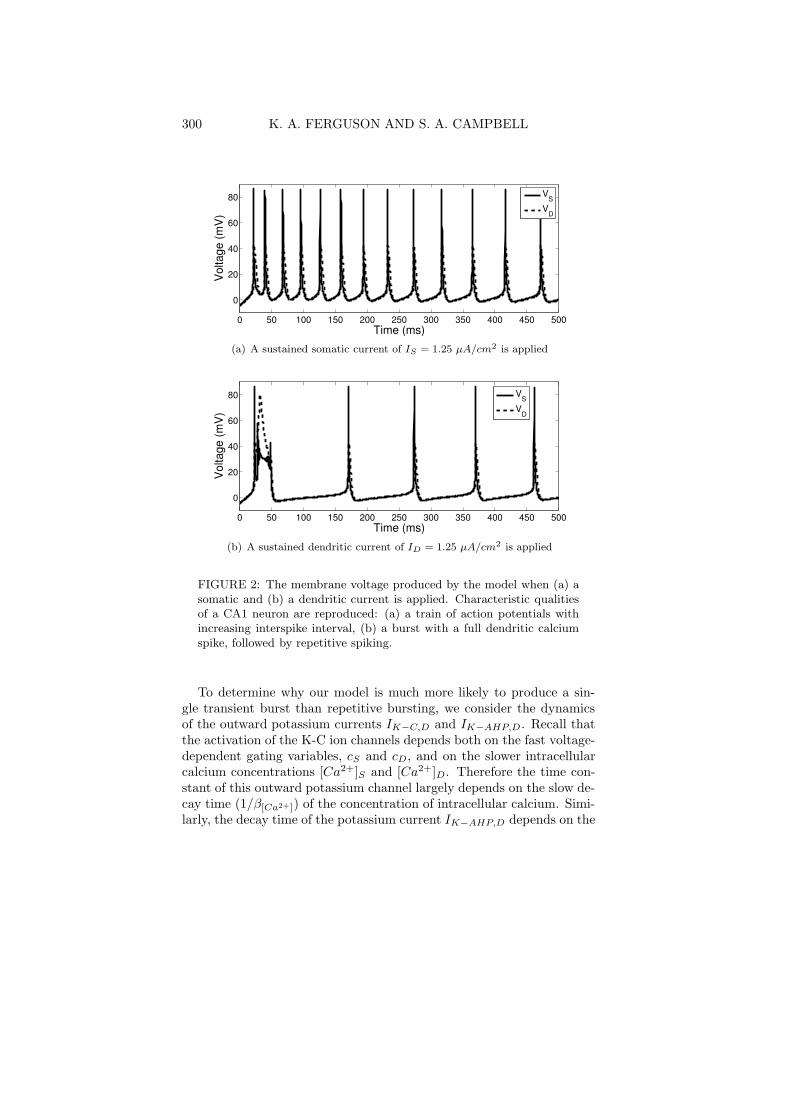
2.1 Single cell model results By injecting a sustained current intoour somatic compartment (IS) and later into our dendritic compartment(ID), we reproduced behaviour found experimentally and obtained withthe 19-compartment model of [9]. When a sustained current is appliedto the somatic compartment, a steady train of somatic action poten-tials is produced with no bursting (Figure 2(a), cf. with Figure 12of [9]). The amplitude and frequency of both the somatic and den-dritic voltage spikes are very similar to those obtained with Traub et
al.’s 19 compartment model, which are consistent with experimentallyobserved values [8]. The interspike interval (i.e., the interval betweenaction potentials) lengthens over time, which is consistent with exper-imental findings for CA1 neurons [4, 7, 8]. When a current of thesame strength is applied to the dendritic compartment, our model accu-rately simulates the dendritic calcium spike and somatic burst observedexperimentally [12]. The single burst is followed by a series of actionpotentials as seen in the simulations of Traub’s 19 compartment model.These results are shown in Figure 2(b) (cf. Figure 12 of [9]). The ac-
A TWO COMPARTMENT MODEL 299
tion potentials occur at a lower frequency than when the same currentis applied to the somatic compartment. This is due to the increasedcalcium-dependent outward potassium channel (IK−AHP,D) triggeredby the large dendritic calcium spike, resulting in a longer afterhyperpo-larization. For the simulations in Figure 2, we use a constant appliedcurrent of either IS or ID = 1.25 µA/cm2 (which translates to ap-proximately 0.48 nA in Traub’s model), while the current in the othercompartment is held constant at −0.25 µA/cm2. We have chosen thisvalue so that it is slightly below the rheobase—the minimum amountof current required to excite the neuron—which is found to be approx-imately −0.175 µA/cm2 when p = 0.5. We did so in accordance with[9], who applied a small negative current to suppress spontaneous fir-ing. The coupling parameters are kept for now at the standard valuesof gC = 1.5 mS/cm2 and p = 0.5. Keeping all other parameters fixed,spiking behaviour with physiologically reasonable frequencies was ob-served for 1.25 µA/cm2 ≤ IS < 3.5 µA/cm2 and bursting behaviourwas observed for 0.5 µA/cm2 ≤ ID < 4 µA/cm2.
As with Pinsky and Rinzel’s [6] CA3 model, our model only demon-strates the desired characteristic CA1 behaviour for a limited range ofthe coupling conductance, gC . A very large coupling conductance essen-tially makes our model a single compartment model, and a very smallgC leaves us with isolated compartments. However, if gC is slightly re-duced then no bursting occurs, and if gC is slightly increased then ape-riodic bursting occurs. Using an applied current of ID = 1.25 µA/cm2,the desired bursting behaviour is reproduced for 1.35 mS/cm2 ≤ gC ≤1.7 mS/cm2.
2.2 Bursting mechanics When a moderate sustained current is ap-plied to the dendritic compartment, a somatic transient burst results(Figure 3(a)). To explain this burst qualitatively, we examine a singleisolated model CA1 neuron with no synaptic input. Keeping the cou-pling parameters at their usual values of gC = 1.5 mS/cm2 and p = 0.5,and maintaining IS = −0.25 µA/cm2, a constant applied dendritic cur-rent of ID = 1.25 µA/cm2 is used to create the initial burst followed bythe action potential shown in Figure 3(a). We find that the interplaybetween the outward dendritic currents IK−C,D and IK−AHP,D with theinward dendritic current ICa,D is the primary cause of bursting. Sincethe calcium-dependent potassium currents are essential to the burstingbehaviour, we look at the associated variables [Ca2+]S , [Ca2+]D , qS andqD. In addition, the coupling parameters gC and p are identified as keyelements in generating this characteristic behaviour.
300 K. A. FERGUSON AND S. A. CAMPBELL
0 50 100 150 200 250 300 350 400 450 500
0
20
40
60
80
Time (ms)
Vol
tage
(mV
)
VS
VD
(a) A sustained somatic current of IS = 1.25 µA/cm2 is applied
0 50 100 150 200 250 300 350 400 450 500
0
20
40
60
80
Time (ms)
Vol
tage
(mV
)
VS
VD
(b) A sustained dendritic current of ID = 1.25 µA/cm2 is applied
FIGURE 2: The membrane voltage produced by the model when (a) asomatic and (b) a dendritic current is applied. Characteristic qualitiesof a CA1 neuron are reproduced: (a) a train of action potentials withincreasing interspike interval, (b) a burst with a full dendritic calciumspike, followed by repetitive spiking.
To determine why our model is much more likely to produce a sin-gle transient burst than repetitive bursting, we consider the dynamicsof the outward potassium currents IK−C,D and IK−AHP,D . Recall thatthe activation of the K-C ion channels depends both on the fast voltage-dependent gating variables, cS and cD, and on the slower intracellularcalcium concentrations [Ca2+]S and [Ca2+]D. Therefore the time con-stant of this outward potassium channel largely depends on the slow de-cay time (1/β[Ca2+]) of the concentration of intracellular calcium. Simi-larly, the decay time of the potassium current IK−AHP,D depends on the
A TWO COMPARTMENT MODEL 301
slow gating variable qD, which is also a function of [Ca2+]D. Thus thedendritic calcium spikes repolarize in accordance with the time constantsof the slow variables [Ca2+]S , [Ca2+]D, qS and qD. During the burst,the length of the “quiet period” of VS—when the soma is overdriven—isalso determined mainly by these slow variables. From Figure 3(b) it isevident that the levels of qS and qD are low at the time of bursting, andare significantly elevated during the action potentials. High q valuespermit greater outward flow of IK−AHP , allowing the voltage to recoverfaster, thereby reducing the probability of bursting. Similarly, the in-tracellular calcium concentration is low during the initiation of a burst(Figure 3(a)). An increased level of [Ca2+] activates the K-C channelsdirectly (and K-AHP channels indirectly), permitting the compartmen-tal voltage to repolarize faster. This faster recovery implies a decreasedchance of bursting, resulting in single action potentials (Figure 3(a)). Incontrast, a large dendritic calcium conductance, gCa,D, creates a largeinward calcium current flow. This makes it difficult for the outwardpotassium currents to counteract the inward flow, increasing the possi-bility of a burst.
The coupling parameters, gC and p, play an essential role in gener-ating bursts. Increased coupling results in increased flow of electrotoniccurrent, elevating the q and [Ca2+] levels, as well as the inward currentflow. Although the model will be more effective in creating the bursts,it will also recover faster, shortening the length of the burst. Thus, ifthe coupling parameter gC is increased, the greater current flow betweenthe two compartments will be more effective at initiating a burst. Simi-larly, the effects of the two compartments depend on their proportionalsize, p: the larger the dendritic compartment is compared to the somaticcompartment, the more influence it will have.
3 Coupled cell model When excited, the presynaptic neuron re-leases neurotransmitters into the synaptic cleft to signal its postsynapticneighbour. According to Pinsky and Rinzel [6] and Traub et al. [10],the AMPA synapse is the dominant mechanism involved in the synchro-nization of two pyramidal neurons. Using this knowledge, we construct astandard AMPA synapse model [2] which synchronizes coupled cell mod-els under a strong connection, and desynchronizes the coupled modelsimmediately once the strong connection is removed.
Since we have multiple cell models, we attach a subscript to our vari-ables to denote the appropriate cell to which it belongs. Consider twocells, a presynaptic cell (cell 2) and a postsynaptic cell (cell 1). Using the
302 K. A. FERGUSON AND S. A. CAMPBELL
(a)
0 50 100 150 2000
0.05
0.1
0.15
0.2
Time (ms)
q
q1
q2
(b)
FIGURE 3: (a) The somatic and dendritic intracellular calcium concen-trations, [Ca2+]S and [Ca2+]D (in grey), overlaying the bursting andspiking. (b) qS and qD for the burst and spike sequence in (a). There-fore an applied dendritic current of ID = 1.25 µA/cm2 results in thesame voltage burst and spike. It is evident that increased levels of theslow variables [Ca2+]S, [Ca2+]D, qS , and qD decrease bursting activity.The characteristic transient burst occurs because of the initially low qvalues.
gating variable W1 and the maximal conductance gAMPA1, we represent
the synaptic current due to the AMPA receptors by
(7) IAMPA1= gAMPA1
W1(VD1− VEXC),
where VD1is the voltage of the dendritic compartment of the postsy-
naptic cell, and the reversal potential of the excitatory synapse is given
A TWO COMPARTMENT MODEL 303
by VEXC = 60 mV in accordance with Traub et al. [9]. The presynap-tic voltage is denoted VS2
and VD2for somatic and dendritic voltage
respectively. During a signal (or spike) from the presynaptic cell, thepresynaptic voltage increases. If VS2
surpasses some threshold, VW , thenthe AMPA current of the postsynaptic cell activates with a time con-stant of 1 ms. Otherwise, the current will not activate. The activationdegrades with a time constant τW . This is modelled via the followingequation
(8)dW1
dt= H(VS2
− VW ) −W1
τW
where H(x) is the Heaviside function: H(x) = 1 if x ≥ 0, H(x) =0 otherwise. We set VW = 40 mV and τW = 2 ms in accordancewith Traub [10] and Nadkarni and Jung [5]. To maintain a biologicallyrealistic model, the two individual cell models should not be identical.Thus, we alter some variables of “cell 2” slightly, while keeping themclose to the values for cell 1.
3.1 Coupled cell results Traub et al. [9] stated that the AMPAsynapse is primarily responsible for the synchronization of two neurons,and that when AMPA blockers are applied, the neurons are reported todesynchronize rapidly. To demonstrate that this characteristic is upheldin our model, we couple two cell models with an AMPA synapse andapply a constant input to the dendritic compartment of each cell. Cell1 receives a stronger dendritic input than cell 2 and hence undergoes alonger burst and subsequently spikes at a faster rate that cell 2. With aweak AMPA connection the cells do not synchronize, but with a strongenough AMPA connection, they do. These results are illustrated inFigure 4
Similar results are obtained when the cells receive a sinusoidal inputto the somatic compartment. We set the frequency and strength ofthe input to be different for both cell 1 and cell 2, so the cells do notsynchronize on their own. If the neuron models are connected with asufficiently strong AMPA conductance, then the cell with the weakerinput will synchronize to the cell with the stronger input. We showan example of these results in Figure 5, where the cells are connectedstrongly (gAMPA1
= gAMPA2= 0.2 mS/cm2) until t = 500 ms, and
weakly (gAMPA1= gAMPA2
= 0.01 mS/cm2) after t = 500 ms. We setthe input to be IScell1
(t) = IS1sin(2πt/100) + 1 so IScell1
(t) fluctuatesbetween −0.25 and 2.25. Similarly we set IScell2
nection: gAMPA2= 0.04 mS/cm2. (b) A strong AMPA connection:
gAMPA2= 0.2 mS/cm2.
4 Discussion Due to their susceptibility to excessive bursting andthe organized nature of the hippocampal CA1 region, CA1 pyramidalneurons have been a focus of research involving seizure activity for manyyears [8, 9]. Biophysical models of these neurons exist [8, 9], but forlarge networks or the analysis of key characteristics, a simpler model maybe required. Thus, we created a two-compartment model of hippocam-pal CA1 neurons. The model reproduces qualitatively and quantitativelymuch of the characteristic behaviour of a CA1 neuron, as identified by[9]. That is, when the soma or proximal dendrites are stimulated witha current less than 1 nA (IS < 1 nA), a train of action potentialsis exhibited. However, if the same current stimulates the distal den-
A TWO COMPARTMENT MODEL 305
0 200 400 600 800 1000 1200−10
10
30
50
70
90
Vol
tage
(mV
)
0 200 400 600 800 1000 1200
0
1
2
3
4
I S1 (µ
A/c
m2 )
VS
1
IS
1
(a)
0 200 400 600 800 1000 1200−10
10
30
50
70
90
Vol
tage
(mV
)
0 200 400 600 800 1000 1200
0
1
2
3
4
I S1 (µ
A/c
m2 )
VS
2
IS
1
(b)
FIGURE 5: (a) The voltage of cell 1 and its corresponding input,IScell1
(t). Note the synchronization to its input. (b) The voltage ofcell 2 and the input from cell 1, IScell1
(t). Cell 2 is synchronized to cell1 until t = 500 ms, at which point it desynchronizes. At t = 500 ms theconnection goes from strong to weak, and the applied sinusoidal currentto cell 2 dominates.
drites (ID < 1 nA), a full dendritic calcium spike with somatic burstis produced, followed by low frequency action potentials. The burstingmechanisms were analyzed in detail, and the slow variables q and [Ca2+]were shown to influence the generation of a burst and the length of theinterspike interval. It is clear from our analysis that a two compartmentmodel is the minimal conductance based model which can reproducethe appropriate bursting behaviour. The benefit of our simplified modelis that key parameters involved in characteristic behaviour can be ana-lyzed, and since it maintains its biological relevance, predictions aboutpotential behavioural responses can be made. In addition, computa-
306 K. A. FERGUSON AND S. A. CAMPBELL
tional efficiency ensures that large networks can be created easily. As afirst step toward such network models, we have implemented an AMPAsynapse model and used it to investigate synchronization of two coupledCA1 neurons.
REFERENCES
1. P. Andersen, R. Morris, D. Amaral, T. Bliss and J. O’Keefe, The HippocampusBook, Oxford University Press, New York, NY, 2007.
2. A. Destexhe, Z. F. Mainen and T. J. Sejnowski, Kinetic models of synaptictransmission, in Methods in Neuronal Modeling, Ch. 1, MIT Press, Cambridge,USA, 1998.
3. G. B. Ermentrout, Simulating, analyzing, and animating dynamical systems:a guide to XPPAUT for researchers and students, Soc. Industrial Appl. Math.,Philadelphia, P.A., USA, 2002.
4. T. H. Lanthorn, J. Storm and P. Andersen, Current-to-frequency transductionin CA1 hippocampal pyramidal cells: slow prepotentials dominate the primaryrange firing, Experimental Brain Research 53 (1984), 431–443.
5. Suhita Nadkarni and Peter Jung, Synaptic inhibition and pathologic hyperex-citability through enhanced neuron-astrocyte interaction: A modeling study,J.Integrative Neuroscience 4(2) (2005), 207–226.
6. Paul F. Pinsky and John Rinzel, Intrinsic and network rhythmogenesis in areduced Traub model for CA3 neurons, J. Comput. Neuroscience 1 (1994),39–60.
7. P. A. Schwartzkroin, Secondary range rhythmic spiking in hippocampal neu-rons, Brain Research 149 (1978), 247–250.
8. Roger D. Traub and R. Llinas, Hippocampal pyramidal cells: significance ofdendritic ionic conductances for neuronal function and epileptogenesis, J. Neu-rophysiology 42(2) (1979), 476–495.
9. Roger D. Traub, Robert K. S. Wong, Richard Miles and Hillary Michelson,A model of a CA3 hippocampal pyramidal neuron incorporating voltage-clampdata on intrinsic conductances, J. Neurophysiology 66(2) (1991), 635–650.
10. Roger D. Traub, Richard Miles and Gyorgy Buzsaki, Computer simulation ofcarbachol-driven rhythmic population oscillations in the CA3 region of the invitro rat hippocampus, J. Physiology 451 (1992), 653–672.
11. S. F. Traynelis and R. Dingledine, Potassium-induced spontaneous electro-graphic seizures in the rat hippocampal slice, J. Neurophysiology 59 (1988),259–276.
12. R. K. S. Wong and R. D. Traub, The dendrites and somata of hippocampalpyramidal cells generate different action potential patterns, Soc. Neurosci. Ab-stracts 8 (1982), 412.
13. World Health Organization, Epilepsy: key facts, World Health Organization,Available from http://www.who.int/mediacentre/factsheets/fs999/en/index.html, 2009; url:http://www.who.int/mediacentre/factsheets/fs999/en/index.html, 2009.
Department of Physiology, University of Toronto, Toronto ONToronto Western Research Institute,University Health Network, Toronto ON
A TWO COMPARTMENT MODEL 307
Corresponding author: Sue Ann CampbellDepartment of Applied Mathematics, University of Waterloo,Waterloo ON N2L 3G1E-mail address: [email protected]