1 A Wide-area, Low-latency, and Power-efficient 6-DoF Pose Tracking System for Rigid Objects Young-Ho Kim, Ankur Kapoor, Tommaso Mansi, and Ali Kamen Position sensitive detectors (PSDs) offer possibility to track single active marker’s two (or three) degrees of freedom (DoF) position with a high accuracy, while having a fast response time with high update frequency and low latency, all using a very simple signal processing circuit. However they are not particularly suitable for 6-DoF object pose tracking system due to lack of orientation measurement, limited tracking range, and sensitivity to environmental variation. We propose a novel 6-DoF pose tracking system for a rigid object tracking requiring a single active marker. The proposed system uses a stereo-based PSD pair and multiple Inertial Measurement Units (IMUs). This is done based on a practical approach to identify and control the power of Infrared-Light Emitting Diode (IR-LED) active markers, with an aim to increase the tracking work space and reduce the power consumption. Our proposed tracking system is validated with three different work space sizes and for static and dynamic positional accuracy using robotic arm manipulator with three different dynamic motion patterns. The results show that the static position root-mean-square (RMS) error is 0.6 mm. The dynamic position RMS error is 0.7-0.9 mm. The orientation RMS error is between 0.04 ◦ and 0.9 ◦ at varied dynamic motion. Overall, our proposed tracking system is capable of tracking a rigid object pose with sub-millimeter accuracy at the mid range of the work space and sub-degree accuracy for all work space under a lab setting. Index Terms—6-DoF pose tracking , Position sensitive detector (PSD), Inertia measurement unit (IMU), Sensor fusion, Active markers, Calibration, Infrared sensors, Dynamic pose measurement errors I. I NTRODUCTION Position sensitive detectors (PSDs) have become one of the most important components in the 2 or 3 degree-of- freedom (DoF) position tracking system for various applica- tions [1, 2, 3, 4] (e.g., primarily based on lasers for measuring distance, displacement, and vibration), for which they provide high position resolution, fast response time, while being rather cost-effective and requiring simple signal conditioning circuits. Despite advantages, PSDs are not generally used for 6-DoF object pose tracking system (position and orientation). This is primarily based on three reasons; 1) a single marker orientation can not be captured using a PSD alone, 2) a multi-marker recognition is required for orientation estimation and that is not readily feasible due to multiple markers’ line-of-sight and extra computation to identify the markers and compute the pose, and 3) sensitivity of positional accuracy to active light source usually a light emitting diode (LED) to interference such as ambient light. In this paper, we propose a new 6-DoF pose tracking system, enabling us to accurately track low power active markers within a large work space with high update rate and low latency. More specifically, the system has the following characteristics and novelties: • The proposed system comprises of two main components; (1) a tracking-base unit (TBU), housing two PSDs arranged with a fixed baseline to allow for position triangulation, and an inertial measurement unit (IMU) for a reference coordinate system; (2) a compact size of tracked-object unit (TOU), which could be a set of active makers consisting of multiple infrared light emitting diodes (IR-LEDs) along with an inertia measurement unit (IMU). Y.-H Kim, A. Kapoor, T. Mansi, and A. Kamen are with Siemens Healthineers, Digital Technology & Innovation, Princeton, NJ, USA {young-ho.kim, ankur.kapoor, tommaso.mansi, ali.kamen}@siemens-healthineers.com • A practical IR-LED identification methodology is proposed for a low-latency tracking and a noise filtering. This is primarily due to the limitation of PSDs in doing position sensing only for one active marker at a time and vulnerability to external IR ambient noise. • An adaptable incident power control method is introduced to ensure optimal power consumption for the active markers and increase the tracking range. • An overall calibration method using a highly accurate po- sitioning system such as a commercial robotic manipulator is provided to properly fuse the rotational and translation information read from the PSDs and IMUs. • We finally integrate our tracking system with an ultrasound machine in order to track ultrasound probes, and demonstrate pose tracking performance in a lab environment. II. BACKGROUND AND RELATED WORKS There are three main categories of contact-less technologies to perform 6-DoF rigid object pose tracking; 1) Electromag- netic tracking system (ETS), 2) Optical-based tracking system (OTS), 3) Other sensor fusions. Electromagnetic Tracking System (ETS) is mainly com- prised of a stationary magnetic field generator, coil sensors attached to tracked objects, and a control unit. The magnetic field generator generates a magnetic field and establish a ref- erence coordinate system. The coil sensors are attached to the tracked object, and coils induce a voltage due to magnetic field effect. The control unit operates the magnetic field generator, infers 6-DoF pose information from the coil sensors’ voltages, and transfers the information to the host system [5]. ETS has a small size of coil sensors (e.g., 1 mm in diameter and less than 10 mm in length), and does not require line-of-sight clearance. However, the tethered connection between the coil sensors and the control unit is cumbersome, and ETS accuracy is adversely affected by the presence of ferromagnetic object within the arXiv:2109.07428v1 [cs.RO] 15 Sep 2021
Transcript
1
A Wide-area, Low-latency, and Power-efficient 6-DoF Pose TrackingSystem for Rigid Objects
Young-Ho Kim, Ankur Kapoor, Tommaso Mansi, and Ali KamenPosition sensitive detectors (PSDs) offer possibility to track single active marker’s two (or three) degrees of freedom (DoF) position
with a high accuracy, while having a fast response time with high update frequency and low latency, all using a very simple signalprocessing circuit. However they are not particularly suitable for 6-DoF object pose tracking system due to lack of orientationmeasurement, limited tracking range, and sensitivity to environmental variation. We propose a novel 6-DoF pose tracking systemfor a rigid object tracking requiring a single active marker. The proposed system uses a stereo-based PSD pair and multiple InertialMeasurement Units (IMUs). This is done based on a practical approach to identify and control the power of Infrared-Light EmittingDiode (IR-LED) active markers, with an aim to increase the tracking work space and reduce the power consumption. Our proposedtracking system is validated with three different work space sizes and for static and dynamic positional accuracy using robotic armmanipulator with three different dynamic motion patterns. The results show that the static position root-mean-square (RMS) erroris 0.6 mm. The dynamic position RMS error is 0.7-0.9 mm. The orientation RMS error is between 0.04 and 0.9 at varied dynamicmotion. Overall, our proposed tracking system is capable of tracking a rigid object pose with sub-millimeter accuracy at the midrange of the work space and sub-degree accuracy for all work space under a lab setting.
Index Terms—6-DoF pose tracking , Position sensitive detector (PSD), Inertia measurement unit (IMU), Sensor fusion, Activemarkers, Calibration, Infrared sensors, Dynamic pose measurement errors
I. INTRODUCTION
Position sensitive detectors (PSDs) have become one ofthe most important components in the 2 or 3 degree-of-freedom (DoF) position tracking system for various applica-tions [1, 2, 3, 4] (e.g., primarily based on lasers for measuringdistance, displacement, and vibration), for which they providehigh position resolution, fast response time, while being rathercost-effective and requiring simple signal conditioning circuits.
Despite advantages, PSDs are not generally used for 6-DoFobject pose tracking system (position and orientation). This isprimarily based on three reasons; 1) a single marker orientationcan not be captured using a PSD alone, 2) a multi-markerrecognition is required for orientation estimation and that isnot readily feasible due to multiple markers’ line-of-sight andextra computation to identify the markers and compute thepose, and 3) sensitivity of positional accuracy to active lightsource usually a light emitting diode (LED) to interferencesuch as ambient light.
In this paper, we propose a new 6-DoF pose trackingsystem, enabling us to accurately track low power activemarkers within a large work space with high update rate andlow latency. More specifically, the system has the followingcharacteristics and novelties:• The proposed system comprises of two main components;
(1) a tracking-base unit (TBU), housing two PSDs arrangedwith a fixed baseline to allow for position triangulation,and an inertial measurement unit (IMU) for a referencecoordinate system; (2) a compact size of tracked-object unit(TOU), which could be a set of active makers consistingof multiple infrared light emitting diodes (IR-LEDs) alongwith an inertia measurement unit (IMU).
Y.-H Kim, A. Kapoor, T. Mansi, and A. Kamen are with SiemensHealthineers, Digital Technology & Innovation, Princeton, NJ, USAyoung-ho.kim, ankur.kapoor, tommaso.mansi,[email protected]
• A practical IR-LED identification methodology is proposedfor a low-latency tracking and a noise filtering. This isprimarily due to the limitation of PSDs in doing positionsensing only for one active marker at a time and vulnerabilityto external IR ambient noise.
• An adaptable incident power control method is introducedto ensure optimal power consumption for the active markersand increase the tracking range.
• An overall calibration method using a highly accurate po-sitioning system such as a commercial robotic manipulatoris provided to properly fuse the rotational and translationinformation read from the PSDs and IMUs.
• We finally integrate our tracking system with an ultrasoundmachine in order to track ultrasound probes, and demonstratepose tracking performance in a lab environment.
II. BACKGROUND AND RELATED WORKS
There are three main categories of contact-less technologiesto perform 6-DoF rigid object pose tracking; 1) Electromag-netic tracking system (ETS), 2) Optical-based tracking system(OTS), 3) Other sensor fusions.
Electromagnetic Tracking System (ETS) is mainly com-prised of a stationary magnetic field generator, coil sensorsattached to tracked objects, and a control unit. The magneticfield generator generates a magnetic field and establish a ref-erence coordinate system. The coil sensors are attached to thetracked object, and coils induce a voltage due to magnetic fieldeffect. The control unit operates the magnetic field generator,infers 6-DoF pose information from the coil sensors’ voltages,and transfers the information to the host system [5]. ETS has asmall size of coil sensors (e.g., 1 mm in diameter and less than10 mm in length), and does not require line-of-sight clearance.However, the tethered connection between the coil sensors andthe control unit is cumbersome, and ETS accuracy is adverselyaffected by the presence of ferromagnetic object within the
arX
iv:2
109.
0742
8v1
[cs
.RO
] 1
5 Se
p 20
21
2
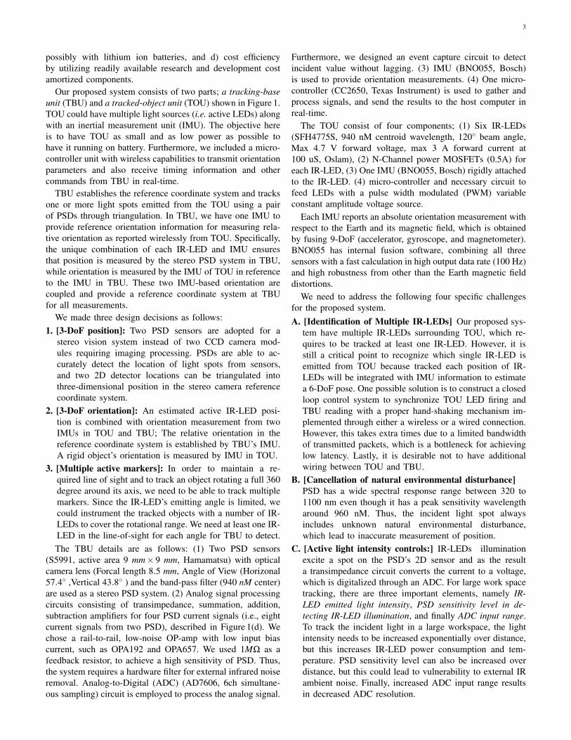
Fig. 1. The proposed system consists of the tracking-base unit (TBU) and the tracked-object unit (TOU). (a)(b) TOU consists of multiple IR-LEDs (Centroidwavelength is 940nM.) along with one IMU. The IMU of TOU orientation information is transferred to the TBU via a wireless connection. (c)(d) TBU hastwo PSDs as a pair with a bandpass filter and transimpedance circuits. IR-LEDs incident light positions on each PSD are digitized by an ADC and processedto micro-controller via an analog signal processing circuit.
magnetic field of the field generator. Moreover, the trackingdistance is limited up to 30 cm, and the performance dependson the distance from the field generator [6, 7].
There exist two typical Optical Tracking Systems (OTS):Infrared (IR)-based and video-metric-based tracking system.Depending on the type of fiducial markers used, IR-basedtracking system can be categorized as either passive (i.e.using retro-reflective material) or active (i.e. IR emitting). Theprinciple of tracking is based on triangulation and registrationof a marker cluster, which is in fact a set of fiducial markerswithin a known geometry fixed to the tracked object. 3-DoF locations of each marker are estimated via triangulationwhere 3-DoF orientations are determined via registration tothe known marker cluster geometry, requiring a high resolu-tion/low latency cameras and non-trivial computations [5].
The number and spatial distribution of the fiducial markerssignificantly influence the tracking accuracy of the OTS. Atleast three visible and non-collinear markers are requiredto uniquely determine 6-DoF pose of the object. Moreover,the lighting conditions including natural environmental dis-turbance (e.g., background illumination) may influence thetracking performance. The fiducial markers forming a markercluster are usually spatially distributed to provide a large lever-arm to provide rotational accuracy. Marker cluster size andthe direct line-of-sight clearance are among disadvantages ofOTS [8, 9].
Video-metric-based tracking system is primarily relying onfeature detection and image registration techniques for trackingobjects. For example, a wearable 6-DoF hand pose trackingsystem is proposed for virtual reality application using a blobdetection and tracking image processing algorithms for 3-DoFposition tracking and IMU for 3-DoF orientation [10]. Garonand Lalonde [11] introduced a temporal 6-DoF pose trackingsystem using deep learning algorithms with data augmentation.Deng et al. [12] used a particle filter with deep learningmethods to estimate 6-DoF targeted objects from cameraimages. In another example, Dong et al. [13] demonstrateddata-driven methods to estimate a tracked object pose usinga convolution neural network. These methods do not requiremarkers, however training samples from the tracked object areneeded to properly train the pose inference model. Moreover,the tracking accuracy is still limited as compared to OTS
and ETS, which are capable of tracking the objects’ posewith sub-millimeter and sub-degree accuracy with low latency(30−80 Hz) under an ideal setting.
Additionally, there exist multiple sensor-fusion-based 6-DoFpose tracking systems proposed in the literature. For example,Han et al. [14] proposed a mobile robot pose tracking systemfor an augmented reality application, which integrated poseinformation from a radiofrequency-based pose tracking systemwith that from a vision-based tracking system. Electromagnetictracking (5-DoF) and IMU (3-DoF) tracking data are fused toarrive at a full 6-D pose tracking resulted in [15]. Esslingeret al. [16] proposed a pose tracking system based on an opto-acoustic system and IMU, in which the fusing is done usinga particle filtering approach.
PSD provides a continuous position measurement of theincident light spot on a surface featuring a special monolithicPIN photodiode with several electrodes placed along each sideof the square near the sensor boundary [17]. The currentscollected from the electrodes directly provide the incidentlight position with a simple circuitry, which has nanoscaleposition and time resolutions leading to a fast response timeand a high accuracy position tracking system. Lee et al. [1]used two PSD sensors to track 3-DoF position as a stereovision system. PSD is utilized for visual servoing and controlapplications [2]. Yang and Wu [4] used PSD for measuring astring vibration primarily due its fast response time. Qu et al.[3] applied PSD-based position detection system for a closed-loop control of a solar tracking mobile robot. There are alsowork done in literature to better characterize the performanceof PSD based systems. Rodrıguez-Navarro et al. [18] proposeda mathematical model and a calibration method to do accuratemeasurements using PSDs. PSD errors are analyzed in termsof component tolerances, temperature variations, signal tonoise ratio, operational amplifier parameters, and analog todigital converter quantization [19]. In addition, Lu et al. [20]presented a quantitative analysis on the position error causedby the changes in the light spot diameter and the distance.
III. MATERIALS AND METHODS
Our objectives for the proposed system is to achieve a) highaccuracy over a large work-space, b) high update rate alongwith low latency, c) power efficiency to operate the sensors
3
possibly with lithium ion batteries, and d) cost efficiencyby utilizing readily available research and development costamortized components.
Our proposed system consists of two parts; a tracking-baseunit (TBU) and a tracked-object unit (TOU) shown in Figure 1.TOU could have multiple light sources (i.e. active LEDs) alongwith an inertial measurement unit (IMU). The objective hereis to have TOU as small and as low power as possible tohave it running on battery. Furthermore, we included a micro-controller unit with wireless capabilities to transmit orientationparameters and also receive timing information and othercommands from TBU in real-time.
TBU establishes the reference coordinate system and tracksone or more light spots emitted from the TOU using a pairof PSDs through triangulation. In TBU, we have one IMU toprovide reference orientation information for measuring rela-tive orientation as reported wirelessly from TOU. Specifically,the unique combination of each IR-LED and IMU ensuresthat position is measured by the stereo PSD system in TBU,while orientation is measured by the IMU of TOU in referenceto the IMU in TBU. These two IMU-based orientation arecoupled and provide a reference coordinate system at TBUfor all measurements.
We made three design decisions as follows:1. [3-DoF position]: Two PSD sensors are adopted for a
stereo vision system instead of two CCD camera mod-ules requiring imaging processing. PSDs are able to ac-curately detect the location of light spots from sensors,and two 2D detector locations can be triangulated intothree-dimensional position in the stereo camera referencecoordinate system.
2. [3-DoF orientation]: An estimated active IR-LED posi-tion is combined with orientation measurement from twoIMUs in TOU and TBU; The relative orientation in thereference coordinate system is established by TBU’s IMU.A rigid object’s orientation is measured by IMU in TOU.
3. [Multiple active markers]: In order to maintain a re-quired line of sight and to track an object rotating a full 360degree around its axis, we need to be able to track multiplemarkers. Since the IR-LED’s emitting angle is limited, wecould instrument the tracked objects with a number of IR-LEDs to cover the rotational range. We need at least one IR-LED in the line-of-sight for each angle for TBU to detect.The TBU details are as follows: (1) Two PSD sensors
(S5991, active area 9 mm× 9 mm, Hamamatsu) with opticalcamera lens (Forcal length 8.5 mm, Angle of View (Horizonal57.4 ,Vertical 43.8 ) and the band-pass filter (940 nM center)are used as a stereo PSD system. (2) Analog signal processingcircuits consisting of transimpedance, summation, addition,subtraction amplifiers for four PSD current signals (i.e., eightcurrent signals from two PSD), described in Figure 1(d). Wechose a rail-to-rail, low-noise OP-amp with low input biascurrent, such as OPA192 and OPA657. We used 1MΩ as afeedback resistor, to achieve a high sensitivity of PSD. Thus,the system requires a hardware filter for external infrared noiseremoval. Analog-to-Digital (ADC) (AD7606, 6ch simultane-ous sampling) circuit is employed to process the analog signal.
Furthermore, we designed an event capture circuit to detectincident value without lagging. (3) IMU (BNO055, Bosch)is used to provide orientation measurements. (4) One micro-controller (CC2650, Texas Instrument) is used to gather andprocess signals, and send the results to the host computer inreal-time.
The TOU consist of four components; (1) Six IR-LEDs(SFH4775S, 940 nM centroid wavelength, 120 beam angle,Max 4.7 V forward voltage, max 3 A forward current at100 uS, Oslam), (2) N-Channel power MOSFETs (0.5A) foreach IR-LED, (3) One IMU (BNO055, Bosch) rigidly attachedto the IR-LED. (4) micro-controller and necessary circuit tofeed LEDs with a pulse width modulated (PWM) variableconstant amplitude voltage source.
Each IMU reports an absolute orientation measurement withrespect to the Earth and its magnetic field, which is obtainedby fusing 9-DoF (accelerator, gyroscope, and magnetometer).BNO055 has internal fusion software, combining all threesensors with a fast calculation in high output data rate (100 Hz)and high robustness from other than the Earth magnetic fielddistortions.
We need to address the following four specific challengesfor the proposed system.A. [Identification of Multiple IR-LEDs] Our proposed sys-
tem have multiple IR-LEDs surrounding TOU, which re-quires to be tracked at least one IR-LED. However, it isstill a critical point to recognize which single IR-LED isemitted from TOU because tracked each position of IR-LEDs will be integrated with IMU information to estimatea 6-DoF pose. One possible solution is to construct a closedloop control system to synchronize TOU LED firing andTBU reading with a proper hand-shaking mechanism im-plemented through either a wireless or a wired connection.However, this takes extra times due to a limited bandwidthof transmitted packets, which is a bottleneck for achievinglow latency. Lastly, it is desirable not to have additionalwiring between TOU and TBU.
B. [Cancellation of natural environmental disturbance]PSD has a wide spectral response range between 320 to1100 nm even though it has a peak sensitivity wavelengtharound 960 nM. Thus, the incident light spot alwaysincludes unknown natural environmental disturbance,which lead to inaccurate measurement of position.
C. [Active light intensity controls:] IR-LEDs illuminationexcite a spot on the PSD’s 2D sensor and as the resulta transimpedance circuit converts the current to a voltage,which is digitalized through an ADC. For large work spacetracking, there are three important elements, namely IR-LED emitted light intensity, PSD sensitivity level in de-tecting IR-LED illumination, and finally ADC input range.To track the incident light in a large workspace, the lightintensity needs to be increased exponentially over distance,but this increases IR-LED power consumption and tem-perature. PSD sensitivity level can also be increased overdistance, but this could lead to vulnerability to external IRambient noise. Finally, increased ADC input range resultsin decreased ADC resolution.
4
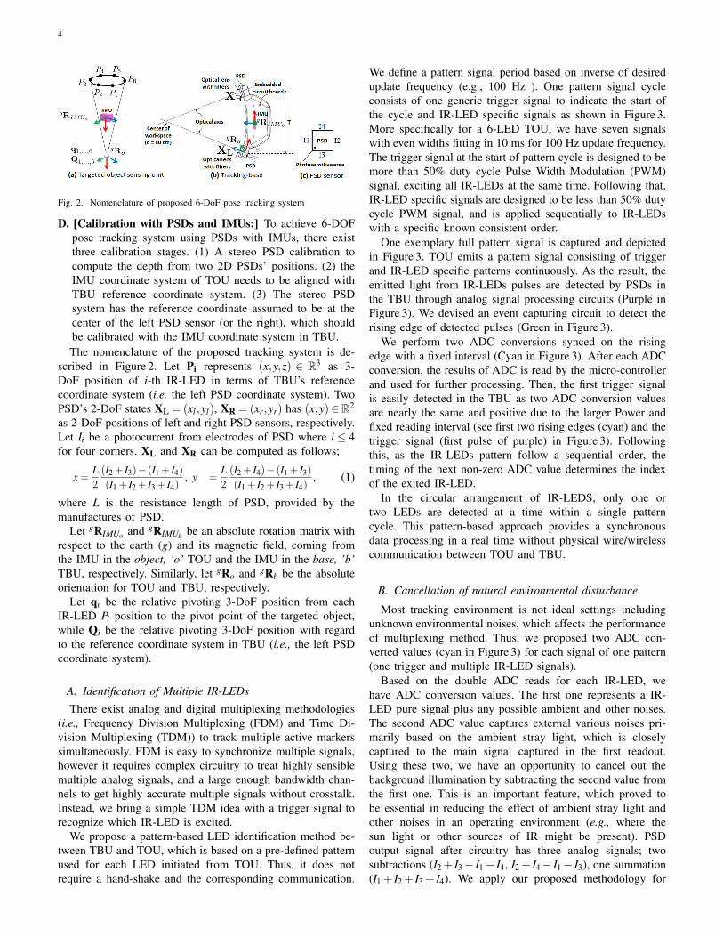
Fig. 2. Nomenclature of proposed 6-DoF pose tracking system
D. [Calibration with PSDs and IMUs:] To achieve 6-DOFpose tracking system using PSDs with IMUs, there existthree calibration stages. (1) A stereo PSD calibration tocompute the depth from two 2D PSDs’ positions. (2) theIMU coordinate system of TOU needs to be aligned withTBU reference coordinate system. (3) The stereo PSDsystem has the reference coordinate assumed to be at thecenter of the left PSD sensor (or the right), which shouldbe calibrated with the IMU coordinate system in TBU.The nomenclature of the proposed tracking system is de-
scribed in Figure 2. Let Pi represents (x,y,z) ∈ R3 as 3-DoF position of i-th IR-LED in terms of TBU’s referencecoordinate system (i.e. the left PSD coordinate system). TwoPSD’s 2-DoF states XL = (xl ,yl), XR = (xr,yr) has (x,y)∈R2
as 2-DoF positions of left and right PSD sensors, respectively.Let Ii be a photocurrent from electrodes of PSD where i≤ 4for four corners. XL and XR can be computed as follows;
x =L2(I2 + I3)− (I1 + I4)
(I1 + I2 + I3 + I4), y =
L2(I2 + I4)− (I1 + I3)
(I1 + I2 + I3 + I4), (1)
where L is the resistance length of PSD, provided by themanufactures of PSD.
Let gRIMUo and gRIMUb be an absolute rotation matrix withrespect to the earth (g) and its magnetic field, coming fromthe IMU in the object, ’o’ TOU and the IMU in the base, ’b’TBU, respectively. Similarly, let gRo and gRb be the absoluteorientation for TOU and TBU, respectively.
Let qi be the relative pivoting 3-DoF position from eachIR-LED Pi position to the pivot point of the targeted object,while Qi be the relative pivoting 3-DoF position with regardto the reference coordinate system in TBU (i.e., the left PSDcoordinate system).
A. Identification of Multiple IR-LEDs
There exist analog and digital multiplexing methodologies(i.e., Frequency Division Multiplexing (FDM) and Time Di-vision Multiplexing (TDM)) to track multiple active markerssimultaneously. FDM is easy to synchronize multiple signals,however it requires complex circuitry to treat highly sensiblemultiple analog signals, and a large enough bandwidth chan-nels to get highly accurate multiple signals without crosstalk.Instead, we bring a simple TDM idea with a trigger signal torecognize which IR-LED is excited.
We propose a pattern-based LED identification method be-tween TBU and TOU, which is based on a pre-defined patternused for each LED initiated from TOU. Thus, it does notrequire a hand-shake and the corresponding communication.
We define a pattern signal period based on inverse of desiredupdate frequency (e.g., 100 Hz ). One pattern signal cycleconsists of one generic trigger signal to indicate the start ofthe cycle and IR-LED specific signals as shown in Figure 3.More specifically for a 6-LED TOU, we have seven signalswith even widths fitting in 10 ms for 100 Hz update frequency.The trigger signal at the start of pattern cycle is designed to bemore than 50% duty cycle Pulse Width Modulation (PWM)signal, exciting all IR-LEDs at the same time. Following that,IR-LED specific signals are designed to be less than 50% dutycycle PWM signal, and is applied sequentially to IR-LEDswith a specific known consistent order.
One exemplary full pattern signal is captured and depictedin Figure 3. TOU emits a pattern signal consisting of triggerand IR-LED specific patterns continuously. As the result, theemitted light from IR-LEDs pulses are detected by PSDs inthe TBU through analog signal processing circuits (Purple inFigure 3). We devised an event capturing circuit to detect therising edge of detected pulses (Green in Figure 3).
We perform two ADC conversions synced on the risingedge with a fixed interval (Cyan in Figure 3). After each ADCconversion, the results of ADC is read by the micro-controllerand used for further processing. Then, the first trigger signalis easily detected in the TBU as two ADC conversion valuesare nearly the same and positive due to the larger Power andfixed reading interval (see first two rising edges (cyan) and thetrigger signal (first pulse of purple) in Figure 3). Followingthis, as the IR-LEDs pattern follow a sequential order, thetiming of the next non-zero ADC value determines the indexof the exited IR-LED.
In the circular arrangement of IR-LEDS, only one ortwo LEDs are detected at a time within a single patterncycle. This pattern-based approach provides a synchronousdata processing in a real time without physical wire/wirelesscommunication between TOU and TBU.
B. Cancellation of natural environmental disturbance
Most tracking environment is not ideal settings includingunknown environmental noises, which affects the performanceof multiplexing method. Thus, we proposed two ADC con-verted values (cyan in Figure 3) for each signal of one pattern(one trigger and multiple IR-LED signals).
Based on the double ADC reads for each IR-LED, wehave ADC conversion values. The first one represents a IR-LED pure signal plus any possible ambient and other noises.The second ADC value captures external various noises pri-marily based on the ambient stray light, which is closelycaptured to the main signal captured in the first readout.Using these two, we have an opportunity to cancel out thebackground illumination by subtracting the second value fromthe first one. This is an important feature, which proved tobe essential in reducing the effect of ambient stray light andother noises in an operating environment (e.g., where thesun light or other sources of IR might be present). PSDoutput signal after circuitry has three analog signals; twosubtractions (I2 + I3− I1− I4, I2 + I4− I1− I3), one summation(I1 + I2 + I3 + I4). We apply our proposed methodology for
5
Fig. 3. Pattern-based IR-LEDs identification: We demonstrate one exemplarypattern signal (a trigger signal + multiple IR-LED signals) to explain theoverall process. In reality, only one and two IR-LEDs are detected due togeometry constraints.
these three analog signals in a real-time (i.e., 50 us capturingdelay for each signal).
Overall, the advantages of this method are; (1) there is notime consuming hand-shake involving back and forth commu-nication is required, (2) the external IR ambient noise can bealleviated, and finally (3) the centralized control system of IR-LEDs facilitates further the power adjustment and control fora large work-space, which we will be further explained in thenext section.
C. Active light intensity controls
IR-LED power needs to be continuously adjusted to providebetter signal and overall accuracy specifically in scenarioswhere the distance between the TBU and TOU is large or steeporientation of TOU causes decreased signal from IR-LEDs.The basic idea is to construct a closed loop power controllerand a look-up-table to adjust the power range depending ondistance. Given fixed PSD sensitivity level, and ADC rangeof inputs, the operational maximum power is a non-linearfunction of distance between the source and the detector. Weconstruct the function as target = LUT (d,R), where d = xl−xris the sensor-based disparity (inversely proportional to thedistance between the source and the detector), and R isthe orientation of TOU in terms of TBU coordinate system(detailed computation will be addressed in Section III-D).
Active power controller algorithm is addressed in Algo-rithm 1. The inputs are two summation values (∑ Il , ∑ Ir) fromtwo PSDs, xl , xr, and R. During the operation, LUT (·) returns
Algorithm 1: LIGHT INTENSITY CONTROLSINPUT: the look-up-table for power limits LUT(·), the
sum currents of left/right PSDs ∑ Il and ∑ Ir,x-axis positions of left/right PSDs xl and xr(d = xl− xr), the orientation R
OUTPUT: error1 error = 0;2 while PSD pose tracking system is OPERATIONAL do3 target = LUT(d, R) ;4 error = target−max(∑ Il ,∑ Ir) ;
Fig. 4. Stereo PSD calibration for IR-LEDs: (a) 4x3 checkerboard is designedand used for stereo calibration. IR-band is not visible, so a single opticalcamera without IR-filter lens used to show how IR-LEDs are operated, whichare emitted periodically. (b) 12 points detected by each PSD (left and right)are plotted in 2-DoF plane; the red is for XL, and the blue is for XR.
the reference power level. The discrepancy between the valuesdenoted as error is transferred to the TOU wirelessly allowingfor the the power level of IR-LED to be controlled in real-time.
D. Calibration Procedure
We have mainly two calibration challenges; 1) PSD basedstereo-camera calibration within in TBU, 2) 3-DoF positionand 3-DoF orientation calibration within a unified coordinatesystem for TOU in terms of TBU.
1) Stereo PSD calibrationTwo PSDs are setup as a stereo camera system, where each
PSD gives the 2D image point of LED point source, XL, XR(Figure 4(b)). Therefore similar to a stereo vision calibration,the PSD stereo calibration can be resolved using an intrinsicand extrinsic calibration steps. The intrinsic calibration pa-rameters consist of the focal length, the principal point, skewangle and the ones related to distortion. Aside from distortionparameters, the focal length, skew angle, and the principalpoint are directly analogous to those from commonly usedcameras.
To obtain projected points, we use a grid of IR-LEDs (i.e. tosimulate an optical checkerboard) that is fabricated to certaintolerance to project 4× 3 points in space (Figure 4(a)). Thecheckerboard is moved around to cover the entire work-spacearea. Both the standard optical system parameters and thedistortion coefficient are obtained using an iterative algorithmof projecting known points, de-warping and recasting them inthe 3D space. Once the individual PSDs have been calibrated,we proceed with the calibration of extrinsic parameters ofstereo rig, which is formulated as the relative orientation andtranslation of the right PSD senor system with respect tothe left PSD sensor. The extrinsic calibration parameters arecomputed using an iterative approach detailed in [21].
The distortion for PSD is different from CMOS/CCD typesensors used in computer vision. The typical biconvex lensesused to focus light produce barrel distortions, whereas thesensor itself produces a pincushion distortion.
Ideally if the electrical center of PSD and the optical centerof lens coincide the two can almost cancel out. However, thismay not be achieved in practice. Therefore, we use a two
6
dimensional Bernstein basis polynomials of degree n to modelthe inverse of distortion. The formulation is as follows;
(x, y) = ∑∑βi jbni j(x,y) (2)
To obtain true 3D positions of IR-LED points, we apply theinverse of distortion modeled as in Equation (2) to the PSDsmeasured pixels (XL, XR) prior to 3D reconstruction of thepoint (Pi).
2) Calibration of IMU and PSD coordinate systemThe 3-D position of the IR-LED source (i.e., attached to
the tracked object) with respect to the left PSD coordinatesystem is given by Pi. The 3-D orientation of the IMU inTOU is provided by gRIMUo with respect to the gravity andthe magnetic north. If the fixed relative orientation betweenthe tracked object body and the attached IMU is given byIMUoRo, then the 3D orientation of the body with respect togravity and magnetic north is follows:
gRo =g RIMUo ×IMUo Ro. (3)
Likewise, the relative orientation of the IMU attached toTBU is given by gRIMUb and the fixed relative orientationbetween the left PSD coordinate system and the attached IMUon TBU is given by IMUbRb. Thus, the left PSD orientation(i.e., tracking base) with respect to gravity and magnetic northis given by
gRb =g RIMUb ×
IMUb Rb. (4)
Based on these, the 3-DoF orientation of tracked object unitwith respect to left PSD coordinate system is given by
bRo =g R−1
b ×g Ro. (5)
Combination of bRo and Pi, provide full 6 DoF transfor-mation of the tracked object points to the tracking base. Forexample, any point in i-th IR-LED coordinate system such asthe pivot point qi has the following relationship to the samecoordinate denoted in the tracking base coordinate system Qi.
Qi =b Ro×qi +Pi. (6)
Based on these, the three fixed quantities to be derivedor calibrated for the PSD system are; (i) relative orientationbetween tracked object IMU and the tracked object coordinatesystem IMUoRo, (ii) the relative orientation between the IMUand tracking base coordinate systems, IMUbRb, (iii) the relativeposition of a common point such as pivoting point denoted asqi and Qi within TOU coordinate system.
Calibration of (i) IMUoRo:IMUoRo is stemming misalignment between IMU reference andthe tracked object reference coordinate system. In a perfectscenario, this orientation transformation should be close toidentity, but it is not in reality. To estimate IMUoRo, wehave to measure the reference orientation of the tracked rigidobject along TOU coordinate system, which might require thespecialized tool (e.g., a robotic manipulator). Let us have Mnumber of samples for a real measure of gRo, and TOU’s pureIMU measure gRIMUo . Then, we construct an overdeterminedlinear system as follows
(gR jo−g Rk
o)3P×3 = (gR j
IMUo−g Rk
IMUo)3P×3×IMUo Ro, (7)
where j,k ∈ [1,M] and M is the number of samples for gRoand gRIMUo , P is the number of possible pair in [1,M], P > 3,and IMUo Ro is what we want to compute.
To minimize a residual error, we use the pseudo-inverse of(gR j
IMUo−g Rk
IMUo)3P×3 to estimate IMUoRo, then we can com-
pute gRo. More detailed least-squares solution with pseudo-inverse is described in [22].
Calibration of (ii) IMUbRb and (iii) qi:We have to estimate IMUbRb, which is also mostly due tofabrication tolerance. Moreover, in our system, the relativeposition of each LED to the pivot point qi must be determinedin practice. We propose an extended pivot calibration methodto estimate both the tolerance error IMUbRb and each relativepivoting position qi together.
The pivot calibration method evolves basically rotatingand swinging the tracked object about a fixed point, whilemeasuring the pose in both local (i.e., TOU) and global (i.e,TBU). The pivot point is constant within both local and globalcoordinate systems and that is the basis to create an over-complete set of equations.
In our system, each IR-LED needs individual calibration forqi, which is the location of each IR-LED is a coordinate systemestablished at the pivot point. However, IMUbRb is common forall IR-LED. We extend the pivot calibration method for eachIR-LED 3-D position Pi to compute qi where Q1 =Q2 = · · ·=QN is an ideal for all IR-LEDs.
We design an iterative least-square approximate method.Algorithm 2 consisted of three parts; (1) estimation of qi andQi for i-th LED, (2) estimation of IMUbRb for all LEDs, (3)computation of overall errors, and then iterate (1) to (3).
First, we have i-th IR-LED 3-D position Pi with orientationbased on bRo. We treat ∆IMUb Rb
as our estimated value forIMUb Rb, which is initially an identity matrix. Let S j
i = [P j,b R jo]
denote j-th set of position and orientation for i-th LED, wherej ∈ [1,Ni], and Ni is the total number of data set for i-th LED.Then, we can derive an overdetermined linear system for qiand Qi based on Equation (6).
(bRpo −b Rk
o)3H×3×qi = (Pk−Pp)3H×1, (8)
(bRpo−1− bRk
o−1
)3H×3
×Qi = (bRpo−1 ·Pp− bRk
o−1 ·Pk)3H×1, (9)
where p,k ∈ [1,Ni], H is the number of possible pair ∈ [1,Ni].Then, we use the pseudo-inverse to estimate qi and Qi.
2 while MAX-Iteration & errors > threshold do// First: estimation of qi and Q
3 RR = [],T T = [],errors = 0;4 for i = 1 : 6 do5 r = [], t = [],R = [], T = [];6 for j = 1 : Ni−1 do7 bR j
o = ∆IMUb Rb×b R j
o;8 for k = 1+ j : Ni do9 bRk
o = ∆IMUb Rb×b Rk
o;10 r.push(bR j
o−b Rko), t.push(Pk
i −P ji );
11 R.push((bR jo)−1− (bRk
o)−1);
12 T.push((bR jo)−1×P j
i − (bRko)−1×Pk
i );
13 qi = pinv(r)× t ;14 Qi = pinv(R)×T ;15 RR.push(R), T T.push(T );
16 Q = pinv(RR)×T T ;// Second: estimation of IMUb Rb
17 a = [], b = [];18 for i = 1 : 6 do19 for j = 1 : Ni do20 a.push(bR j
o× qi);21 b.push(Q−Pi);
22 ∆IMUb Rb= b× pinv(a) ;
// compute overall errors
23 for i = 1 : 6 do24 for j = 1 : Ni−1 do25 for k = 1+ j : Ni do26 errors += |(bR j
o−b Rko)× qi +P j
i −Pki |;
27 errors += |Qi− (∆IMUb Rb×b R j
o× qi +P ji )|;
28 IMUbRb = ∆IMUb Rb;
where H is the number of possible pair ∈ [1,Ni]. Then, wealso use the pseudo-inverse to estimate IMUbRb (i.e. ∆IMUb Rb
) 1.Finally, we compute overall errors of our estimation and
keep iterating three steps until threshold or max-iteration meet.As a result, we can get qi, Qi, and IMUbRb.
IV. EXPERIMENT AND RESULTS
A. System setup
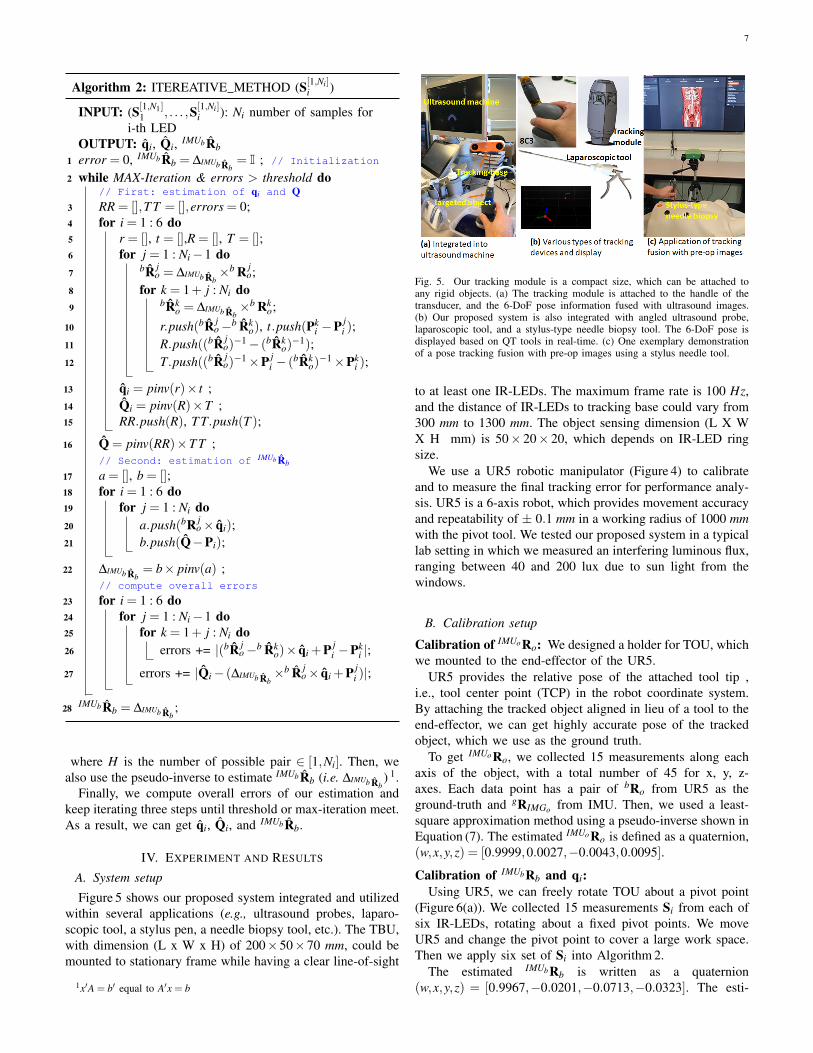
Figure 5 shows our proposed system integrated and utilizedwithin several applications (e.g., ultrasound probes, laparo-scopic tool, a stylus pen, a needle biopsy tool, etc.). The TBU,with dimension (L x W x H) of 200×50×70 mm, could bemounted to stationary frame while having a clear line-of-sight
1x′A = b′ equal to A′x = b
Fig. 5. Our tracking module is a compact size, which can be attached toany rigid objects. (a) The tracking module is attached to the handle of thetransducer, and the 6-DoF pose information fused with ultrasound images.(b) Our proposed system is also integrated with angled ultrasound probe,laparoscopic tool, and a stylus-type needle biopsy tool. The 6-DoF pose isdisplayed based on QT tools in real-time. (c) One exemplary demonstrationof a pose tracking fusion with pre-op images using a stylus needle tool.
to at least one IR-LEDs. The maximum frame rate is 100 Hz,and the distance of IR-LEDs to tracking base could vary from300 mm to 1300 mm. The object sensing dimension (L X WX H mm) is 50× 20× 20, which depends on IR-LED ringsize.
We use a UR5 robotic manipulator (Figure 4) to calibrateand to measure the final tracking error for performance analy-sis. UR5 is a 6-axis robot, which provides movement accuracyand repeatability of ± 0.1 mm in a working radius of 1000 mmwith the pivot tool. We tested our proposed system in a typicallab setting in which we measured an interfering luminous flux,ranging between 40 and 200 lux due to sun light from thewindows.
B. Calibration setup
Calibration of IMUoRo: We designed a holder for TOU, whichwe mounted to the end-effector of the UR5.
UR5 provides the relative pose of the attached tool tip ,i.e., tool center point (TCP) in the robot coordinate system.By attaching the tracked object aligned in lieu of a tool to theend-effector, we can get highly accurate pose of the trackedobject, which we use as the ground truth.
To get IMUoRo, we collected 15 measurements along eachaxis of the object, with a total number of 45 for x, y, z-axes. Each data point has a pair of bRo from UR5 as theground-truth and gRIMGo from IMU. Then, we used a least-square approximation method using a pseudo-inverse shown inEquation (7). The estimated IMUoRo is defined as a quaternion,(w,x,y,z) = [0.9999,0.0027,−0.0043,0.0095].
Calibration of IMUbRb and qi:Using UR5, we can freely rotate TOU about a pivot point
(Figure 6(a)). We collected 15 measurements Si from each ofsix IR-LEDs, rotating about a fixed pivot points. We moveUR5 and change the pivot point to cover a large work space.Then we apply six set of Si into Algorithm 2.
The estimated IMUbRb is written as a quaternion(w,x,y,z) = [0.9967,−0.0201,−0.0713,−0.0323]. The esti-
8
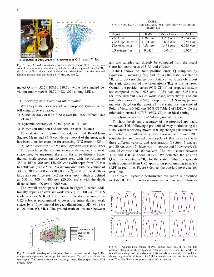
Fig. 6. (a) A holder is attached to the end-effector of UR5, thus we cancontrol the tool center point directly, which provides the ground truth for bRo.(b) A set of Si is plotted with position and orientation. Using the proposediterative method that can estimate IMUb Rb, Q, and qi.
mated Q is (−52.59,108.10,780.70) while the standard de-viation (unit= mm) is (0.79,0.98,1.02) among LEDs.
C. Accuracy assessment and interpretation
We analyze the accuracy of our proposed system in thefollowing three scenarios;1) Static accuracy of 6-DoF pose over the three different size
of area.2) Dynamic accuracy of 6-DoF pose at 100 mm3) Power consumption and temperature over distance
To evaluate the proposed method, we used Root-Mean-Square, Mean, and 95 % confidence interval of the error, as ithas been done for example for assessing OTS errors in [23].
1) Static accuracy over the three different work space sizesTo characterize the system accuracy dependency to work
space size, we measured the error for three different hypo-thetical work spaces; (a) the large area with the volume of350 × 400 × 900 mm (158,500 cm3) with depth from 300 mmto 1300 mm. (b) the large, but narrow area with the volume of300 × 300 × 900 mm (100,000 cm3), amd similar depth aslarge area the large area. (c) the sweet-spot, which is definedas 200 × 300 × 400 mm (20,500 cm3), with the depthdistance from 400 mm to 900 mm.
The overall work space is shown in Figure 7, which addi-tionally depicts an overlaid work space (190,000 cm3 of OTS(Polaris Vicra, NDI [24]). To measure the static accuracy, theUR5 robot is programmed to cover the entire defined workspaces by a 10 cm interval for each dimension in 3D, while wecollect data (Q, bRo). The ground truth of distance between
Fig. 7. Overall boundary of workspaces that we evaluate are displayed. Theorange area represents the large, but narrow are. The red area shows thesweet-spot. The green area shows the large area. The purple shows OTS(Vicra, NDI).
TABLE ISTATIC ACCURACY OF PSD TRACKER, POSITION/ORIENTATION ERROR
STATISTICS
Regions RMS Mean Error 95% CIThe large 1.369 mm 1.237 mm 2.254 mmThe large+narrow 1.171 mm 0.846 mm 1.934 mmThe sweet-spot 0.56 mm 0.434 mm 0.925 mm3D orientation 0.043 0.040 0.059
any two samples can directly be computed from the actualCartesian coordinates of UR5 end-effector.
Table I shows the static position error; Q computed byEquation (6) including bRo and Pi. As the static orientationbRo error does not change over distance, we separately reportthe static accuracy of the orientation (bRo) at the last row.Overall, the position errors (95% CI) of our proposed systemare computed to be 0.925 mm, 1.934 mm, and 2.254 mmfor three different sizes of work space, respectively, and ourorientation error of (0.059) is superior to OTS using passivemarkers. Based on the report [23], the static position error ofPolaris Vicra is 0.462 mm (95% CI Table 2 of [23]), while theorientation errors is 0.713 (95% CI) in an ideal setting.
2) Dynamic accuracy of 6-DoF pose at 100 cmTo show the dynamic accuracy of the proposed approach,
we moved TOU following a pre-defined sway motion using theUR5, which repeatedly moves TOU by changing its translationand rotation simultaneously within range of 75 mm, 20,respectively. We created three cycle of this trajectory withthree different velocity and acceleration; (1) Slow 7 cm/secand 20 cm/sec2, (2) Moderate 14 cm/sec and 50 cm/sec2, (3)Fast 25 cm/sec and 100 cm/sec2. The test distance betweenTBU and TOU is about 100 cm. We collected the positionQ and the orientation bRo, for the system, while the ground-truth is acquired from UR5 application programming interface(API) in real-time. Figure 8 depicts the overlaid pose changesover time.
The overall dynamic performance evaluation is describedin Table II. The orientation errors are within sub-millimeter
Fig. 8. Dynamic pose change of PSD tracker over time at 100 cm. Theposition changes of three dynamic tests are (a), (b), and (c) while theorientation changes of three dynamic tests are (d), (e), and (f). The red lineshows the ground-truth from UR5 API for actual Cartesian coordinates of thetool. The blue line shows pose changes of our tracker.
9
TABLE IIDYNAMIC POSE ACCURACY OF PSD TRACKER, DISTANCE/ORIENTATION
range for all testing conditions. The dynamic position errorincreases as compared to static one by less than a millimeter.Unfortunately, dynamic measurements error are not providedin many related work making it hard to compare. The resultsoverall demonstrates that the proposed system can be a com-petitive system in terms of accuracy for tracking rigid toolsto other commercially available OTS, ETS, and video-metricbased tracking systems.
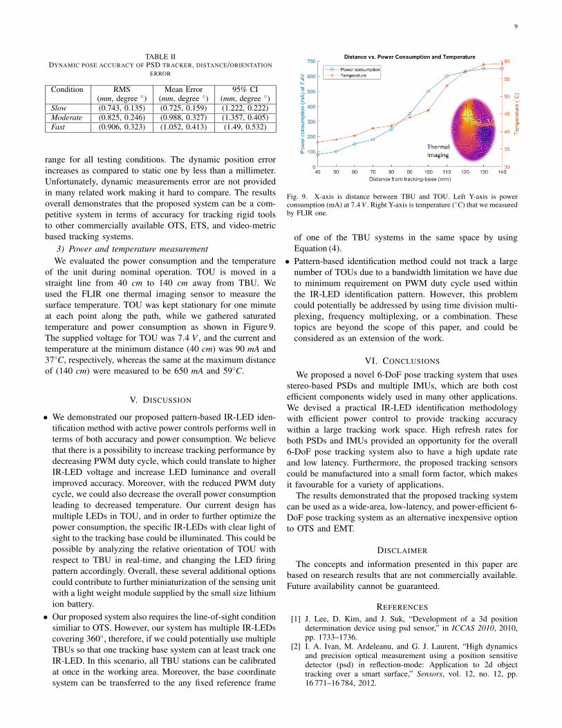
3) Power and temperature measurementWe evaluated the power consumption and the temperature
of the unit during nominal operation. TOU is moved in astraight line from 40 cm to 140 cm away from TBU. Weused the FLIR one thermal imaging sensor to measure thesurface temperature. TOU was kept stationary for one minuteat each point along the path, while we gathered saturatedtemperature and power consumption as shown in Figure 9.The supplied voltage for TOU was 7.4 V , and the current andtemperature at the minimum distance (40 cm) was 90 mA and37C, respectively, whereas the same at the maximum distanceof (140 cm) were measured to be 650 mA and 59C.
V. DISCUSSION
• We demonstrated our proposed pattern-based IR-LED iden-tification method with active power controls performs well interms of both accuracy and power consumption. We believethat there is a possibility to increase tracking performance bydecreasing PWM duty cycle, which could translate to higherIR-LED voltage and increase LED luminance and overallimproved accuracy. Moreover, with the reduced PWM dutycycle, we could also decrease the overall power consumptionleading to decreased temperature. Our current design hasmultiple LEDs in TOU, and in order to further optimize thepower consumption, the specific IR-LEDs with clear light ofsight to the tracking base could be illuminated. This could bepossible by analyzing the relative orientation of TOU withrespect to TBU in real-time, and changing the LED firingpattern accordingly. Overall, these several additional optionscould contribute to further miniaturization of the sensing unitwith a light weight module supplied by the small size lithiumion battery.
• Our proposed system also requires the line-of-sight conditionsimiliar to OTS. However, our system has multiple IR-LEDscovering 360, therefore, if we could potentially use multipleTBUs so that one tracking base system can at least track oneIR-LED. In this scenario, all TBU stations can be calibratedat once in the working area. Moreover, the base coordinatesystem can be transferred to the any fixed reference frame
Fig. 9. X-axis is distance between TBU and TOU. Left Y-axis is powerconsumption (mA) at 7.4 V . Right Y-axis is temperature (C) that we measuredby FLIR one.
of one of the TBU systems in the same space by usingEquation (4).
• Pattern-based identification method could not track a largenumber of TOUs due to a bandwidth limitation we have dueto minimum requirement on PWM duty cycle used withinthe IR-LED identification pattern. However, this problemcould potentially be addressed by using time division multi-plexing, frequency multiplexing, or a combination. Thesetopics are beyond the scope of this paper, and could beconsidered as an extension of the work.
VI. CONCLUSIONS
We proposed a novel 6-DoF pose tracking system that usesstereo-based PSDs and multiple IMUs, which are both costefficient components widely used in many other applications.We devised a practical IR-LED identification methodologywith efficient power control to provide tracking accuracywithin a large tracking work space. High refresh rates forboth PSDs and IMUs provided an opportunity for the overall6-DoF pose tracking system also to have a high update rateand low latency. Furthermore, the proposed tracking sensorscould be manufactured into a small form factor, which makesit favourable for a variety of applications.
The results demonstrated that the proposed tracking systemcan be used as a wide-area, low-latency, and power-efficient 6-DoF pose tracking system as an alternative inexpensive optionto OTS and EMT.
DISCLAIMER
The concepts and information presented in this paper arebased on research results that are not commercially available.Future availability cannot be guaranteed.
REFERENCES
[1] J. Lee, D. Kim, and J. Suk, “Development of a 3d positiondetermination device using psd sensor,” in ICCAS 2010, 2010,pp. 1733–1736.
[2] I. A. Ivan, M. Ardeleanu, and G. J. Laurent, “High dynamicsand precision optical measurement using a position sensitivedetector (psd) in reflection-mode: Application to 2d objecttracking over a smart surface,” Sensors, vol. 12, no. 12, pp.16 771–16 784, 2012.
10
[3] L. Qu, J. Liu, Y. Deng, L. Xu, K. Hu, W. Yang, L. Jin, andX. Cheng, “Analysis and adjustment of positioning error of psdsystem for mobile sof-ftir,” Sensors, vol. 19, no. 23, 2019.
[4] C.-H. Yang and T.-C. Wu, “Vibration measurement method ofa string in transversal motion by using a psd,” Sensors, vol. 17,no. 7, 2017.
[5] E. C. Chen, A. Lasso, and G. Fichtinger, “Chapter 31 - externaltracking devices and tracked tool calibration,” in Handbook ofMedical Image Computing and Computer Assisted Intervention,ser. The Elsevier and MICCAI Society Book Series, S. K. Zhou,D. Rueckert, and G. Fichtinger, Eds. Academic Press, 2020,pp. 777–794.
[6] A. M. Franz, T. Haidegger, W. Birkfellner, K. Cleary, T. M.Peters, and L. Maier-Hein, “Electromagnetic tracking inmedicine—a review of technology, validation, and applications,”IEEE Transactions on Medical Imaging, vol. 33, no. 8, pp.1702–1725, 2014.
[7] G. Andria, F. Attivissimo, A. Di Nisio, A. M. L. Lanzolla,and M. A. Ragolia, “Assessment of position repeatability errorin an electromagnetic tracking system for surgical navigation,”Sensors, vol. 20, no. 4, 2020.
[8] N. D. Glossop, “Advantages of optical compared with electro-magnetic tracking,” Journal of Bone and Joint Surgery, vol. 91,no. 1, pp. 23–28, 2009.
[9] A. Sorriento, M. B. Porfido, S. Mazzoleni, G. Calvosa,M. Tenucci, G. Ciuti, and P. Dario, “Optical and electromagnetictracking systems for biomedical applications: A critical reviewon potentialities and limitations,” IEEE Reviews in BiomedicalEngineering, vol. 13, pp. 212–232, 2020.
[10] A. T. Maereg, E. L. Secco, T. F. Agidew, D. Reid, and A. K.Nagar, “A low-cost, wearable opto-inertial 6-dof hand posetracking system for vr,” Technologies, vol. 5, no. 3, 2017.
[11] M. Garon and J. Lalonde, “Deep 6-dof tracking,” IEEE Transac-tions on Visualization and Computer Graphics, vol. 23, no. 11,pp. 2410–2418, 2017.
[12] X. Deng, A. Mousavian, Y. Xiang, F. Xia, T. Bretl, and D. Fox,“Poserbpf: A rao–blackwellized particle filter for 6-d objectpose tracking,” IEEE Transactions on Robotics, pp. 1–15, 2021.
[13] Y. Dong, L. Ji, S. Wang, P. Gong, J. Yue, R. Shen, C. Chen,and Y. Zhang, “Accurate 6dof pose tracking for texture-lessobjects,” IEEE Transactions on Circuits and Systems for VideoTechnology, pp. 1–1, 2020.
[14] B. Han, Y.-H. Kim, K. Cho, and H. S. Yang, “Museum tourguide robot with augmented reality,” in 2010 16th InternationalConference on Virtual Systems and Multimedia, 2010, pp. 223–229.
[15] H. Dai, S. Song, C. Hu, B. Sun, and Z. Lin, “A novel 6-dtracking method by fusion of 5-d magnetic tracking and 3-dinertial sensing,” IEEE Sensors Journal, vol. 18, no. 23, pp.9640–9648, 2018.
[16] D. Esslinger, P. Rapp, S. Wiertz, H. Rendich, R. Marsden,O. Sawodny, and C. Tarın, “Accurate optoacoustic and iner-tial 3-d pose tracking of moving objects with particle filter-ing,” IEEE Transactions on Instrumentation and Measurement,vol. 69, no. 3, pp. 893–906, 2020.
[18] D. Rodrıguez-Navarro, J. L. Lazaro-Galilea, I. Bravo-Munoz,A. Gardel-Vicente, F. Domingo-Perez, and G. Tsirigotis, “Math-ematical model and calibration procedure of a psd sensor usedin local positioning systems,” Sensors, vol. 16, no. 9, 2016.
[19] D. Rodrıguez-Navarro, J. L. Lazaro-Galilea, I. Bravo-Munoz,A. Gardel-Vicente, and G. Tsirigotis, “Analysis and calibrationof sources of electronic error in psd sensor response,” Sensors,vol. 16, no. 5, 2016.
[20] X. Lu, Y. Xv, W. Wang, Y. Zhou, and S. Y. Liang, “Experimentalstudy of the effect of light source spot size on measure error ofpsd,” International Journal of Manufacturing Research, vol. 14,
no. 1, Dec 2019.[21] J. Bouguet, “Camera calibration toolbox for matlab,” 2001.[22] G. Strang, Linear algebra and its applications. Thomson,
Brooks/Cole, 2006.[23] A. D. Wiles, D. G. Thompson, and D. D. Frantz, “Accuracy
assessment and interpretation for optical tracking systems,”in Medical Imaging 2004: Visualization, Image-Guided Proce-dures, and Display, R. L. G. Jr., Ed., vol. 5367, InternationalSociety for Optics and Photonics. SPIE, 2004, pp. 421 – 432.