32


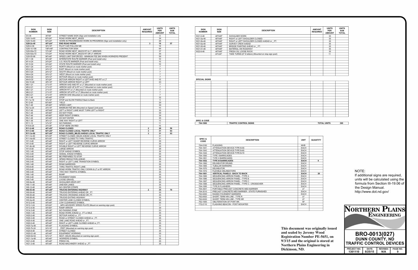
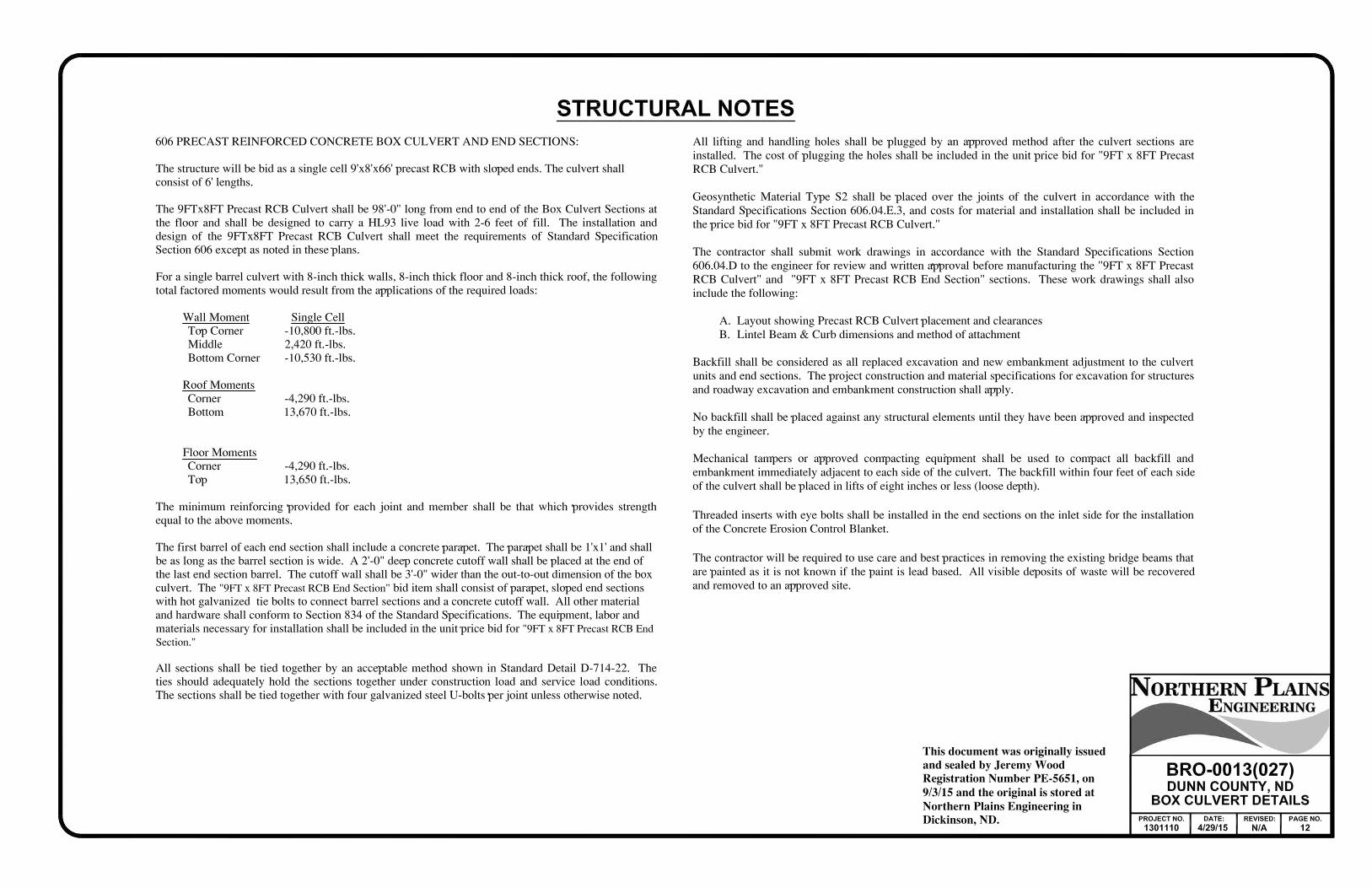
SPEC CODE DESCRIPTION UNIT TOTAL103 0100 CONTRACT BOND L SUM 1202 0105 REMOVAL OF STRUCTURE L SUM 1202 127 REMOVE& SALVAGE CULVERT ALL TYPES & SIZES LF 72203 0103 COMMON EXCAVATION TYPE C CY 6,846203 0109 TOPSOIL CY 1,627210 0050 BOX CULVERT EXCAVATION EA 1210 0201 FOUNDATION PREPARATION EA 1210 0210 FOUNDATION FILL CY 95216 0100 WATER MGAL 98251 0350 SEEDING CLASS III MILE 0.3251 2001 TEMPORARY COVER CROP MILE 0.3253 0101 STRAWMULCH ACRE 2.1255 0300 CONCRETE EROSION CONTROL BLANKET SY 29256 0200 RIPRAP GRADE II CY 88261 0112 FIBER ROLLS 12IN LF 540261 0113 REMOVE FIBER ROLLS 12IN LF 120302 0356 AGGREGATE SURFACE COURSE CL 13 TON 1,302606 0908 9FT X 8FT PRECAST RCB CULVERT LF 66606 4908 9FT X 8FT PRECAST RCB END SECTION EA 2702 0100 MOBILIZATION L SUM 1704 1000 TRAFFIC CONTROL SIGNS UNIT 369704 1052 TYPE III BARRICADE EA 9704 1081 VERTICAL PANELS BACK TO BACK EA 20709 0151 GEOSYNTHETIC MATERIAL TYPE R1 SY 272709 0155 GEOSYNTHETIC MATERIAL TYPE RR SY 96709 0162 GEOSYNTHETIC MATERIAL TYPE S2 SY 129714 4105 PIPE CONDUIT 24IN LF 128754 0110 FLAT SHEETS FOR SIGNS TYPE XI REFL SHEETING SF 5.2754 0112 FLAT SHEETS FOR SIGNS TYPE IV REFL SHEETING SF 3.9754 0206 STEEL GALV POSTS TELESCOPING PERFORATED TUBE LF 25


or `
Abn abandoned
Abut abutment
Ac acres
Adj adjusted
Aggr aggregate
Ahd ahead
ARV valve releaseair
Align alignment
Al alley
Alt alternate
Alum aluminum
ADA Act Disabilities withAmericans
A ampere
& and
Appr approach
Approx approximate
ACP pipe cementasbestos
Asph asphalt
AC cementasphalt
Assmd assumed
@ at
Atten attenuation
ATR recorder trafficautomatic
Ave Avenue
Avg average
ADT traffic dailyaverage
Az azimuth
Bk back
BF faceback
Bs backsight
Balc balcony
WireB wirebarbed
Barr barricade
Btry battery
Brg bearing
BI inletbeehive
Beg begin
BM markbench
Bkwy bikeway
Bit bituminous
Blk block
FtBd feetboard
BH holebore
BS sidesboth
Bot bottom
Blvd Boulevard
Bndry boundary
BC capbrass
Brkwy breakaway
Br bridge
Bldg building
BV valvebutterfly
Byp bypass
GdrlC guardrailcable
Calc calculate
Cd candela
CIP pipe ironcast
CB basincatch
CRS setting rapidcationic
GdC guardcattle
C ToC center tocenter
Cl centerline
Cm centimeter
Ch chain
Chnlk chain-link
BlkCh blockchannel
ChCh changechannel
Chk check
Chsld chiseled
Cir circle
Cl class
Cl clay
FCl fillclay
HvyCl heavyclay
LmCl loamclay
Clnt clean-out
Clr clear
Cl&gr grubbing &clearing
SCo slackcoal
Comb. combination
Coml commercial
Compr compression
CADD design & drafting aidedcomputer
Conc concrete
Cond conductor
Const construction
Cont continuous
CSB sample barrel splitcontinuous
Contr contraction
Contr contractor
CP pointcontrol
Coord coordinate
Cor corner
Corr corrected
CAES section end aluminumcorrugated
CAP pipe aluminumcorrugated
CMES section end metalcorrugated
CMP pipe metalcorrugated
CPVCP pipe chloride poly-vinylcorrugated
CSES section end steelcorrugated
CSP pipe steelcorrugated
C coulomb
Co County
Crse course
GrC gravelcourse
CS sandcourse
Ct Court
Xarm armcross
Xbuck buckcross
Xsec sectionscross
Xing crossing
Xrd Crossroad
Crn crown
CF feetcubic
M3 metercubic
M3/s second per meterscubic
CY yardcubic
Cy/mi mile per yardscubic
Culv culvert
C&G gutter &curb
CI inletcurb
CR rampcurb
CS spiral tocurve
C cut
LdDd loaddead
Defl deflection
Defm deformed
D orDeg degree
Dlnt delineate
Dlntr delineator
Depr depression
Desc description
Det detail
DWP panel warningdetectable
Dtr detour
Dia diameter
Dir direction
Dist distance
DM materialdisturbed
DB blockditch
DG gradeditch
Dbl double
Dn down
Dwg drawing
Dr drive
Drwy driveway
DI inletdrop
D densitydry
Ea each
Esmt easement
E East
EB Eastbound
Elast elastomeric
EL lockerelectric
MtrE meterelectric
Elec electric/al
EDM meter distanceelectronic
El orElev elevation
Ellipt elliptical
Emb embankment
Emuls emulsion/emulsified
ES sectionend
Engr engineer
ESS station sensorenvironmental
Eq equal
Eq equation
Evgr evergreen
Exc excavation
Exst existing
Exp expansion
Expy Expressway
E curve ofexternal
Extru extruded
FOS safety offactor
F Fahrenheit
FS sidefar
F farad
Fed Federal
FP pointfeed
Ft feet/foot
Fn fence
PFn postfence
FO opticfiber
FB bookfield
FD drivefield
F fill
FAA angularity aggregatefine
FS sandfine
FH hydrantfire
Fl flange
Flrd flared
FES section endflared
BcnF beaconflashing
FA sample augerflight
FL lineflow
Ftg footing
FM mainforce
Fs foresight
Fnd found
Fdn foundation
Frac fractional
Frwy freeway
Frt front
FF facefront
DispF dispenserfuel
Ð
lack of description, location accuracy or purpose. an unknown characteristic, potentially based on: of existing features. It indicates a feature that has This is a special text character used in the labeling
REVISIONS
DATE CHANGE
DEPARTMENT OF TRANSPORTATION
NORTH DAKOTA
of Transportation
North Dakota Department
document is stored at the
on and the original
PE- ,
Registration Number
issued and sealed by
This document was originally
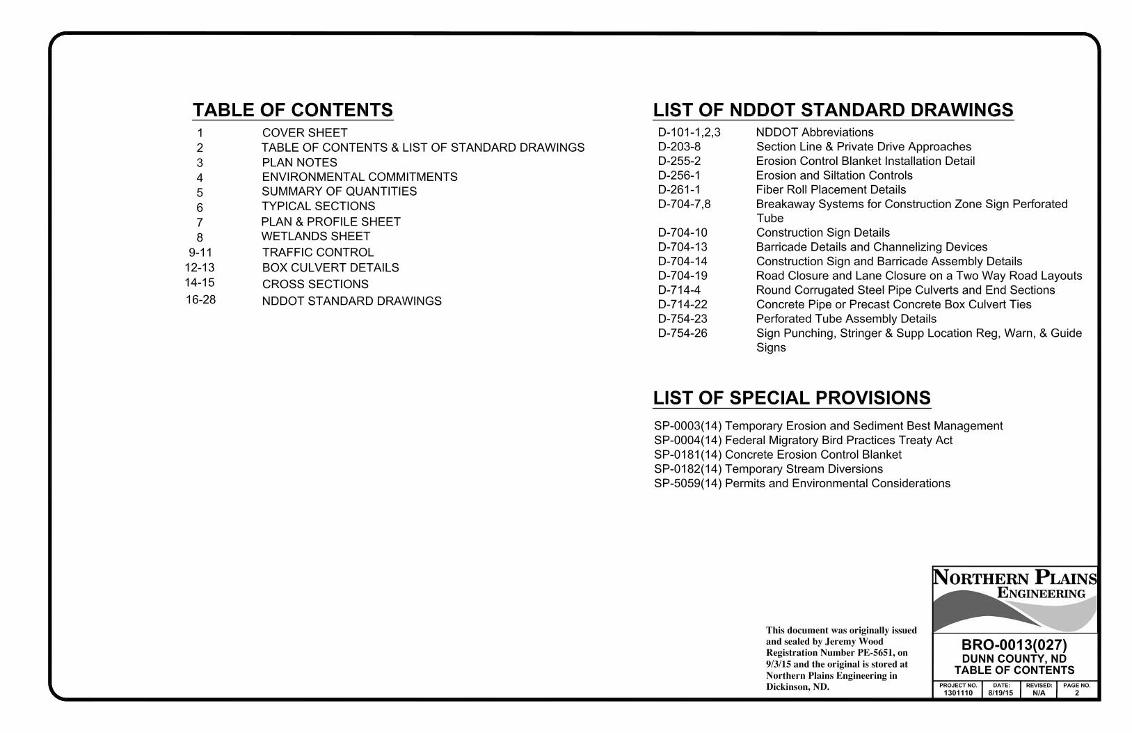
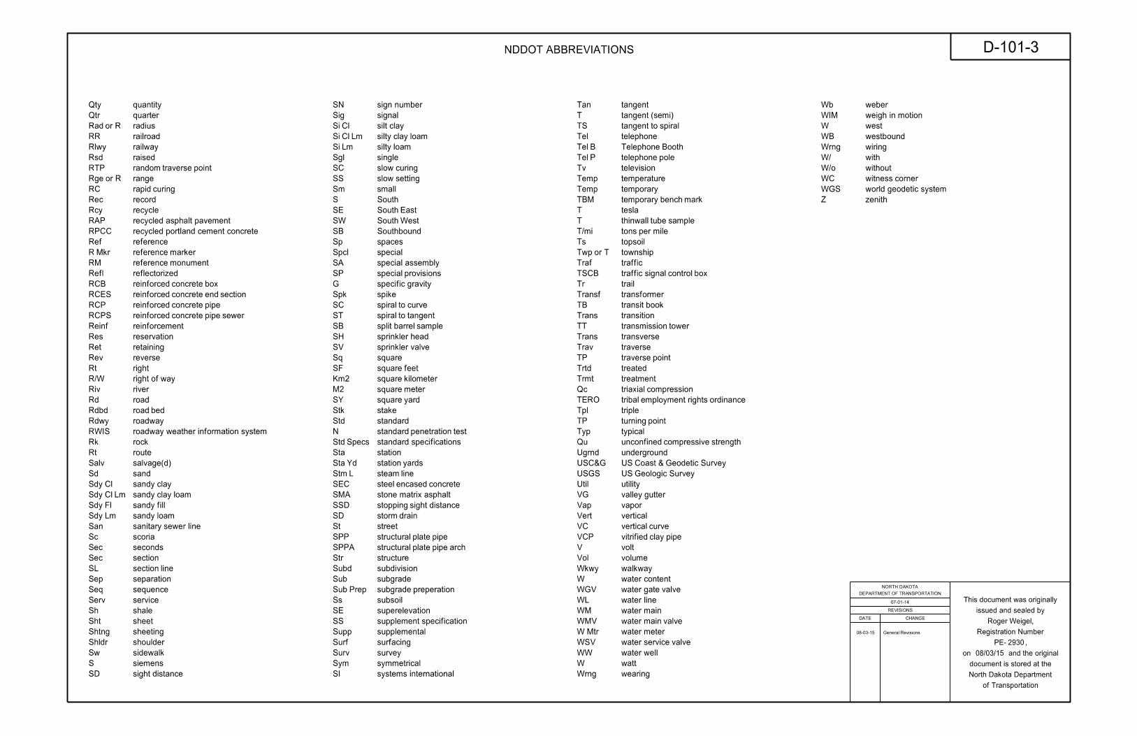
NDDOT ABBREVIATIONS D-101-1
07-01-14
2930
Roger Weigel,
07/01/14
FFP pipes fillerfuel
FLS sensor leakfuel
Furn furnish/ed
Gal gallon
Galv galvanized
Gar garage
LGs linegas
RegG regulator linegas
GMV valve maingas
MtrG metergas
GSV valve servicegas
GVP pipe ventgas
GV valvegate
Ga gauge
Geod geodetic
GIS System InformationGeographical
G giga
GPS System PositioningGlobal
Gov government
Grd graded/grade
Gr gravel
Grnd ground
GWM monitor waterground
Gdrl guardrail
Gtr gutter
PlgH pilingH
Hdwl headwall
Ha hectare
Ht height
HI instrument ofheight
Hel helical
H henry
Hz hertz
HDPE polyethylene densityhigh
HM masthigh
HP pressurehigh
HPS sodium pressurehigh
Hwy highway
Hor horizontal
HBP pavement bituminoushot
Hr hour(s)
Hyd hydrant
Ph content ionhydrogen
Id identification
" orIn inch
Incl tubeinclinometer
IMH manholeinlet
ID diameterinside
Inst instrument
Intchg interchange
Intmdt intermediate
Intscn intersection
Inv invert
IM monumentiron
PnI PinIron
IP Pipeiron
Jt joint
J joule
Jct junction
K kelvin
Kn newtonkilo
Kpa pascalkilo
Kg kilogram
Kg/m3 meter cubic perkilogram
Km kilometer
K Kip(s)
LS (licensed) SurveyorLand
LSIT Training In SurveyorLand
Ln lane
Lg large
Lat latitude
Lt left
L curve oflength
Lens lenses
Lvl level
LB booklevel
Lvlng leveling
Lht light
LP polelight
Ltg lighting
CoLig coallignite
SlLig slacklignite
LF footlinear
Liq liquid
LL limitliquid
L litre
Lm loam
Loc location
LC chordlong
Long. longitude
Lp loop
LD detectorloop
Lm lumen
Lum luminaire
SumL sumlump
Lx lux
ML linemain
HrM hourman
MH manhole
Mkd marked
Mkr marker
Mkg marking
MA armmast
Matl material
Max maximum
MC cornermeander
Meas measure
Mdn median
MD drainmedian
MC curingmedium
M mega
Mer meridian
M meter
M/s second permeters
M curve of ordinatemid
Mi mile
MM markermile
MP postmile
Ml milliliter
Mm millimeter
Mm/hr hour permillimeters
Min minimum
Misc miscellaneous
Mon monument
Mnd mound
Mtbl mountable
Mtd mounted
Mtg mounting
Mk muck
Mun municipal
N nano
NGS Survey GeodeticNational
NS sidenear
Neop neoprene
Ntwk network
N newton
N North
NE EastNorth
NW WestNorth
NB Northbound
# orNo. number
Obsc obscure(d)
Obsn observation
Ocpd occupied
Ocpy occupy
LocOff locationoffice
O/s offset
OC centeron
C consolidation dimensionalone
OC contentorganic
Orig original
O ToO out toout
OD diameteroutside
OH overhead
PMT transformer mountedpad
Pg pages
Pntd painted
Pr pair
Pnl panel
Pk park
PK nailParker-Kalon
Pa pascal
PSD distance sightpassing
Pvmt pavement
Ped pedestal
Ped pedestrian
PPP post pushbuttonpedestrian
Pen. penetration
Perf perforated
Per. perimeter
PL pipeline
Pl place
P&P profile &plan
PL limitplastic
Pl plate
Pt point
PCC curve compound ofpoint
PC curve ofpoint
PI intersection ofpoint
PRC curvature reverse ofpoint
PT tangent ofpoint
POC curve onpoint
POT tangent onpoint
PE polyethylene
PVC chloridepolyvinyl
PCC concrete CementPortland
# orLb pounds
PP polepower
Preempt preemption
Prefab prefabricated
Prfmd preformed
Prep preperation
Press. pressure
PRV valve reliefpressure
Prestr prestressed
Pvt private
PD driveprivate
Prod. production/produce
Prog programmed
Prop. property
LnProp lineproperty
Ppsd proposed
PB boxpull
HMA hot mix asphalt
NDDOT ABBREVIATIONS D-101-2
07-01-14
2930
Roger Weigel,
REVISIONS
DATE CHANGE
DEPARTMENT OF TRANSPORTATION
NORTH DAKOTA
of Transportation
North Dakota Department
document is stored at the
on and the original
PE- ,
Registration Number
issued and sealed by
This document was originally
08/03/15
General Revisions 08-03-15
Qty quantity
Qtr quarter
R orRad radius
RR railroad
Rlwy railway
Rsd raised
RTP point traverserandom
R orRge range
RC curingrapid
Rec record
Rcy recycle
RPCC
Ref reference
MkrR markerreference
RM monumentreference
Refl reflectorized
RCB box concretereinforced
RCES section end concretereinforced
RCP pipe concretereinforced
RCPS sewer pipe concretereinforced
Reinf reinforcement
Res reservation
Ret retaining
Rev reverse
Rt right
R/W way ofright
Riv river
Rd road
Rdbd bedroad
Rdwy roadway
RWIS
Rk rock
Rt route
Salv salvage(d)
Sd sand
ClSdy claysandy
Lm ClSdy loam claysandy
FlSdy fillsandy
LmSdy loamsandy
San line sewersanitary
Sc scoria
Sec seconds
Sec section
SL linesection
Sep separation
Seq sequence
Serv service
Sh shale
Sht sheet
Shtng sheeting
Shldr shoulder
Sw sidewalk
S siemens
SD distancesight
Sig signal
ClSi claysilt
Lm ClSi loam claysilty
LmSi loamsilty
Sgl single
SC curingslow
SS settingslow
Sm small
S South
SE EastSouth
SW WestSouth
SB Southbound
Sp spaces
Spcl special
SP provisionsspecial
G gravityspecific
Spk spike
SC curve tospiral
ST tangent tospiral
SB sample barrelsplit
SH headsprinkler
SV valvesprinkler
Sq square
SF feetsquare
Km2 kilometersquare
M2 metersquare
SY yardsquare
Stk stake
Std standard
N test penetrationstandard
SpecsStd
Sta station
YdSta yardsstation
LStm linesteam
SEC concrete encasedsteel
SSD distance sightstopping
SD drainstorm
St street
SPP pipe platestructural
SPPA arch pipe platestructural
Str structure
Subd subdivision
Sub subgrade
PrepSub preperationsubgrade
Ss subsoil
SE superelevation
SS specificationsupplement
Supp supplemental
Surf surfacing
Surv survey
Sym symmetrical
SI
Tan tangent
T (semi)tangent
TS spiral totangent
Tel telephone
BTel BoothTelephone
PTel poletelephone
Tv television
Temp temperature
Temp temporary
TBM mark benchtemporary
T tesla
T sample tubethinwall
T/mi mile pertons
Ts topsoil
T orTwp township
Traf traffic
TSCB box control signaltraffic
Tr trail
Transf transformer
TB booktransit
Trans transition
TT towertransmission
Trans transverse
Trav traverse
TP pointtraverse
Trtd treated
Trmt treatment
Qc compressiontriaxial
TERO ordinance rights employmenttribal
Tpl triple
TP pointturning
Typ typical
Qu strength compressiveunconfined
Ugrnd underground
USC&G Survey Geodetic & CoastUS
USGS Survey GeologicUS
Util utility
VG guttervalley
Vap vapor
Vert vertical
VC curvevertical
VCP pipe clayvitrified
V volt
Vol volume
Wkwy walkway
W contentwater
WGV valve gatewater
WL linewater
WM mainwater
WMV valve mainwater
MtrW meterwater
WSV valve servicewater
WW wellwater
W watt
Wrng wearing
Wb weber
WIM
W west
WB westbound
Wrng wiring
W/ with
W/o without
WC cornerwitness
WGS
Z zenith
SA special assembly
SN sign number
RAP recycled asphalt pavement
recycled portland cement concrete
roadway weather information system
standard specifications
systems international
weigh in motion
world geodetic system
SMA stone matrix asphalt
REVISIONS
DATE CHANGE
DEPARTMENT OF TRANSPORTATION
NORTH DAKOTA
of Transportation
North Dakota Department
document is stored at the
on and the original
PE- ,
Registration Number
issued and sealed by
This document was originally
NDDOT ABBREVIATIONS D-101-3
07-01-14
2930
Roger Weigel,
08/03/15
General Revisions 08-03-15

12’ 12’ 12’12’
Varies
Clear Zone Varies
Clear Zone Varies
Clear Zone Varies
30’
3:124:1
4:14:1
24:13:1
8:1 8:1
B
B
B
C
B
C
B
B
A
A
4:1 or match existing4:1 or m
atch exi
sting
SECTION A-A
SECTION B-B
SECTION C-CAPPROACH GRADE ON CUT SECTION
APPROACH GRADE ON DEEP FILL SECTION
APPROACH GRADE ON FILL SECTION
‘ of Highway
‘ of Approach
Right of Way
24’
to meet conditions
Length of culvert varies
Existing Ground
–2% Maximum
‘
‘
‘
–2% Maximum
C
C
Storage Platform
Storage Platform
Storage Platform
–2% Maximum
Radius
24’
30’
(28’ on Field & Private)
30’
24’
(28’ on Field & Private)
30’
24’
(28’ on Field & Private)
Maximum Grade
Maximum Grade
Maximum Grade
PLAN VIEW
Toe of Slope
Graded Shoulder
Toe of Slope
Graded Shoulder
Toe of Slope
Graded Shoulder
Graded Shoulder
Toe of Slope
Clear Zone
‘ of Approach ‘ of Approach
60’ Desirable
‘ of Highway ‘ of Highway
Existing Slo
pe
Tra
nsitio
n to
B
B
Existing Slo
pe
Tra
nsitio
n to
Existing Slo
pe
Tra
nsitio
n to
Existing Slo
pe
Tra
nsitio
n to
B
B
CASE 1CASE 2
Slope
8:1
Slope
8:1
Inslo
pe
Existing
Inslo
pe
Existing
Approach Slope
Existing
Approach Slope
Existing
Driving Lane
Edge of 12’
Slope
8:1
Slope
8:1
Inslo
pe
Existing
Inslo
pe
Existing
Approach Slope
Existing
Approach Slope
Existing
Clear Zone
Top of Subgrade
60’ or More
60’ OR MORE FROM ‘
APPROACH PIPE LOCATED
Less than 60’
LESS THAN 60’ OF ‘
APPROACH PIPE LOCATED
Crown*
Crown*
Crown*
Surface
Surface
Surface
Top of Surface
*3.0% crown for gravel surface
*2.1% crown for paved surface
APPROACH INSLOPES
Driving Lane
Edge of 12’
VerticalCurve
VerticalCurve
VerticalCurve
10 ft
20 ft
10%
R=24 ft
Field Drives
Varies (Min. 20 mph)
30 ft
7%
R=40 ft
Public RoadsLow Volume
Vertical Curve Length
Storage Platform
Maximum Grade
Radius
CRITERIA FOR RURAL APPROACH TYPES
the area of mainline inslope influence.
2. The approach slope shall be measured outside
platform and highway shall not exceed 5%.
1. Max breakover between approach storage
NOTES:
10 ft
24 ft
7%
R=30 ft
Private Drives
Approach Culvert Approach Culvert
Note 1
Note 1
Note 1
Ground
Existing
Ground
Existing
Ground
Existing
Approach
Approach
Approach
Existing Ground
Existing Ground
driving lane
Edge of paved
driving lane
Edge of paved
driving lane
Edge of paved
Outside Clear Zone
as Minimum
2-25-14
02/25/14
2930
D-203-8STANDARD RURAL APPROACHES
REVISIONS
DATE CHANGE
DEPARTMENT OF TRANSPORTATION
NORTH DAKOTA
of Transportation
North Dakota Department
document is stored at the
on and the original
PE- ,
Registration Number
issued and sealed by
This document was originally
Roger Weigel

ahead or back.
* This tie may be placed
DETAIL A DETAIL B
Minimum 6" overlap
DETAIL C
*
DETAIL D
*
Minimum 6" overlapflow
DETAILS
DETAIL A
DETAIL BBa
ckslo
pe
CROSS SECTION
DETAIL A
DETAIL D
DETAIL B
Sectio
nCross
BLANKET LAYOUT
DETAIL C
X X X X X X
X X X X X X
X XX X X
X X X X X
X X X X X X
STAPLE PATTERN
"u" staples.
using 8-inch 11 gauge wire
square yard 3.8 staples per
PIPE OUTLETS
PIPE INLETS
overlap
Minimum 2'
ECB
ECB
Ground
Exst.
Ground
Exst.
flow
flow
DETAIL C
undermining on side slopes.
entrenched and stapled to eliminate
Erosion control blanket ends shall be
be installed as shown in "DETAIL C".
erosion control blanket areas shall
Beginning and ending of
Notes:
CHANNEL OR SLOPE INSTALLATION
1'
1'
2'
1'
1'
1'
VARIES1'
1'
CHANNEL OR SLOPE INSTALLATION
20"10"
20"
4'
2'
2'
1'
2'
INSTALLATION AT PIPE ENDS
REVISIONS
DATE CHANGE
DEPARTMENT OF TRANSPORTATION
NORTH DAKOTA
of Transportation
North Dakota Department
document is stored at the
on and the original
PE- ,
Registration Number
issued and sealed by
This document was originally
06/26/14
2930
EROSION AND SILTATION CONTROL
EROSION CONTROL BLANKET INSTALLATION
D-255-2
10-03-13
Roger Weigel06-26-14
number from D-708-5 to D-255-2.Changed standard drawing
Flow
Prote
ctio
n Are
a
Do
wnstre
am
Flow
Flow
Ground
Existing
Length = 2 x basin width
Flow
basin length21
Width =
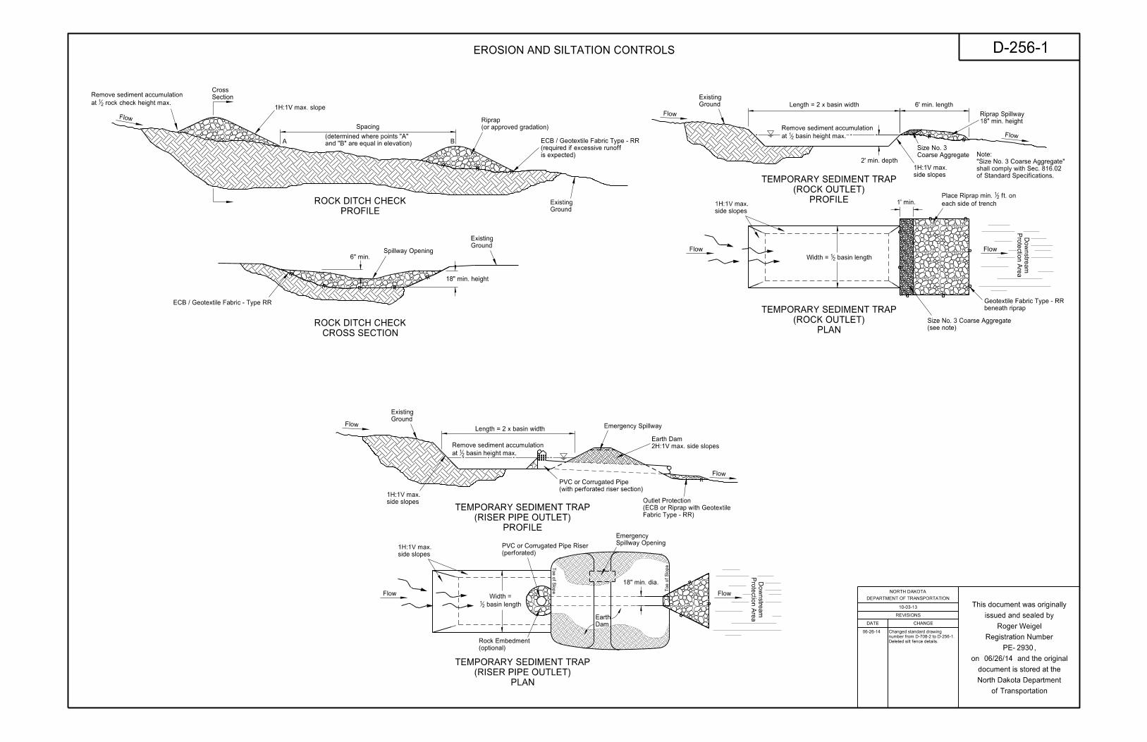
PROFILE
(RISER PIPE OUTLET)
TEMPORARY SEDIMENT TRAP side slopes
1H:1V max.
2H:1V max. side slopes
Earth Dam
Emergency Spillway
18" min. dia.
Dam
Earth
Spillway Opening
Emergency
Toe of Slo
pe T
oe of Slo
pe
(optional)
Rock Embedment
basin height max.21at
Remove sediment accumulation
(with perforated riser section)
PVC or Corrugated Pipe
side slopes
1H:1V max. (perforated)
PVC or Corrugated Pipe Riser
Fabric Type - RR)
(ECB or Riprap with Geotextile
Outlet Protection
PLAN
(RISER PIPE OUTLET)
TEMPORARY SEDIMENT TRAP
18" min. height
Spillway Opening
Flow
6" min.
Ground
Existing
Ground
Existing
Section
Cross
A Band "B" are equal in elevation)
(determined where points "A"
1H:1V max. slope
(or approved gradation)
Riprap
PROFILE
ROCK DITCH CHECK
CROSS SECTION
ROCK DITCH CHECK
Spacing
is expected)
(required if excessive runoff
ECB / Geotextile Fabric Type - RR
ECB / Geotextile Fabric - Type RR
rock check height max.21at
Remove sediment accumulation
Flow
Ground
Existing
Length = 2 x basin width 6' min. length
2' min. depth
Flow
basin length21Width =
each side of trench
ft. on 21Place Riprap min.
18" min. height
Riprap Spillway
PROFILE
(ROCK OUTLET)
TEMPORARY SEDIMENT TRAP
PLAN
(ROCK OUTLET)
TEMPORARY SEDIMENT TRAP
Flow
Prote
ctio
n Are
a
Do
wnstre
am
Flow
side slopes
1H:1V max.
basin height max.21at
Remove sediment accumulation
side slopes
1H:1V max. 1' min.
beneath riprap
Geotextile Fabric Type - RR
of Standard Specifications.
shall comply with Sec. 816.02
"Size No. 3 Coarse Aggregate"
Note:Coarse Aggregate
Size No. 3
(see note)
Size No. 3 Coarse Aggregate
06-26-14
Deleted silt fence details.
number from D-708-2 to D-256-1.
Changed standard drawing
REVISIONS
DATE CHANGE
DEPARTMENT OF TRANSPORTATION
NORTH DAKOTA
of Transportation
North Dakota Department
document is stored at the
on and the original
PE- ,
Registration Number
issued and sealed by
This document was originally
06/26/14
2930
D-256-1
10-03-13
Roger Weigel
EROSION AND SILTATION CONTROLS

Flow
6'
2" to 3"
EROSION CONTROL
6"
Flow
6"
6"
12"
20"
24"
36"
18" 2"
Trenching depth
2" x 2"
2" x 2"
2" x 2"
2"
3"
2"
3"
5"
12"
Fiber Roll
dimensions.
with values for stake and trench
slope application. Added table
Added plan view for ditch and06-10-13
FIBER ROLL PLACEMENT DETAILS
Do not use 20-inch fiber rolls in flat areas where there is potential for water to back up on adjacent property.
on adjacent property. Lower fiber roll enough to prevent water from backing up on adjacent property.
*Optional Weir. Use in flat areas, such as the Red River Valley, where there is potential for water to back up
2" X 2" nominal wood stakes
Fiber Roll Overlapping Staking Detail
Detail A
2" X 2" nominal wood stakes
Detail B
Fiber Roll Staking Detail
from end of roll
Stake 4" to 6"
Side slope
TRENCH DEPTH
MAXIMUM
TRENCH DEPTH
MINIMUM
LENGTH
MINIMUM STAKE
STAKE SIZE
NOMINAL
DIAMETER
FIBER ROLL
PLAN VIEW FOR DITCH APPLICATION
toe of ditch slope
Place stake at each
toe of ditch slope
Place stake at each
from end of roll
Stake 4" to 6"
Side slope
Overlap fiber rolls 12" min.
Detail C
botto
m
Ditch
Flo
w
12 OR 20 INCH FIBER ROLL - DITCH BOTTOM
Ends overlapped 12" minimumfrom end of roll
Stake 4" to 6"
Optional Weir*Detail A
Detail B
Backslope
max.4'
Foreslope
see staking detail
For stake installations
Flo
w
rows of fiber rolls
Stagger joints between
Flo
w
Flo
w
Flo
w
Overlapping fiber rolls
PLAN VIEW FOR SLOPE APPLICATION
NOTE: Runoff must not be allowed to run under or around roll.
see staking detail
For stake installation
along entire length
and 4' max. O.C.
Stake at each end
Detail C
overlap see
For staking of
Flo
w
Soil from trench
Soil from trench
Less than 5"
Less than 5"
10-04-13 Revised fiber roll overlap detail.
Less than 5"
Less than 5"
06-26-14number from D-708-7 to D-261-1.
Changed standard drawing
REVISIONS
DATE CHANGE
DEPARTMENT OF TRANSPORTATION
NORTH DAKOTA
of Transportation
North Dakota Department
document is stored at the
on and the original
PE- ,
Registration Number
issued and sealed by
This document was originally
06/26/14
2930
D-261-1
11-18-10
Roger Weigel,

Top Post Receiver Data Table
A B C D E FSizes (B)
Square Post
Perforated Tube
Slip Base Assembly
Multi-Directional
Bolt Retainer for Base Connection
Ground line
Ground line
12"
25"
15"
3"
4"
"21
"87
"211
2"
2"
"211
"43
1"
"212
8"
"1696
"16155
"16156
"43
60"
6"
6" 6"
3" 3"
4"
24"
1"
1"
12"
6" 6"
7"
1"
1"
"16115
12"
"3293 "32
93
"1652
"833
"1611
"16115
D
E
E
F
"1652
"833
"1611
"1671
"3293 "32
93
"1696
C
A
A
B
A A
60^
6" dia.
6" dia.
6" dia.
9" 9"
60^
Traffic Flo
w
Anchor unit
Ground line
Anchor unit
Post sleeve
"214
Traffic Flo
w
"1671
of Posts
Number
Gauge
ness
Thick-
Wall
Gauge
ness
Thick-
Wall
Base
Slip Gauge
Standard
U.S.
1
1
1
1
1
1
2
2
2
3 & 4
3 & 4
3 & 4
3 & 4
3 & 4
2 12
12
12
12
12
12
12
12
12
12
10
10
10
12
12
12
12
10
No
No
Yes
Yes
Yes
Yes
Yes
Yes
Yes
Yes
Yes
0.105
0.105
0.105
0.135
0.135
12
12
12
12
10
10
1.702
2.416
2.773
3.432
3.141
4.006
0.129
0.372
0.561
0.605
0.804
0.979
0.380
0.590
0.695
0.841
0.803
1.010
0.172
0.372
0.499
0.590
0.643
"3291
"6491
"212
"212
"1653
"3213
"85
"3225
"32211
"64331
"431
"871
"x10 ga.212
"x10 ga.1632
"-13 gr. 8 serrated flange nut21
" U.S.S. steel flat washer21
" stainless release bushing21
" U.S.S. steel flat washer21
" gr. 8 flange bolt43"x22
1
"83
"163
"83
washer and lock washer
" dia. bolt with83
and lock washer or rivet
" dia. bolt with washer83
and lock washer
" dia. bolt with washer83
" dia.169
" dia.212
" Reprocessed Teflon321Bolt Retainer-
in.
of Inertia
Moment
2 x 2
(A)
Telescoping Perforated Tube
163 x 216
32
21 x 22
12
21 x 22
12
41 x 24
12
21 x 12
11
4 2 3in.
Modulus
Section
in.
Sec. Area
Cross
in.
Size
Post
in.
Size
Sleeve
in.
Base
Slip
without
Size
Anchor
412
212
412
412
1632
412
212
212
412
212
412
212
212
212
212
412
212
in.
Thickness
Wall
lbs.
per Foot
Weight
2
2
412
212
2 12 Yes212
2 12 Yes412
2 12 12 Yes4122
12
2 12
10
3
2
No
No
0.105
0.785
Anchor unit
" teflon bolt retainer321
4" max.
4" max.
Anchor Unit and Post Assembly
(one post installation)
minimum 10 gauge
Anchor plate shall be a
(two post installation)
minimum 10 gauge
Anchor plate shall be a
Top Post Receiver
Bottom Soil Stub
in.
Size
Tube
"x10 ga. for additional wind load.21"x10 ga. may be inserted into 216
3(B) The 2
(A) The breakaway base is required when the support is placed in weak soils. The Engineer shall determine if the soils are weak.
Properties of Telescoping Perforated Tube
60"
"165R=
"165R=
and Post Sleeve Assembly
Slip Base Anchor Unit
Multi-Directional
Plate - ASTM A572 grade 50
Stabilizing Wing - 7 gauge H.R.P.O. ASTM A1011
Tube - 3"x3"x7 gauge ASTM A500 grade B tube
5. Four post signs shall have over 7’ between the first and the fourth posts.
4. When used in concrete sidewalk, anchor shall be same except without the wings.
and below post location and also back and ahead of the post.
3. The 4" vertical clearance is required for the anchor or breakaway base. The 4"x60" measurement shall be made above
2. Anchor shall have a yield strength of 43.9 KSI and tensile strength of 59.3 KSI.
1. Slip base bolts shall be torqued as specified by the manufacturer.
Notes:
" ASTM A36 structural angle83"x2
1"x221Angle Receiver - 2
Plate - ASTM A572 grade 50
2-28-14
2930
BREAKAWAY SYSTEMS FOR CONSTRUCTION ZONE SIGNS D-704-7
REVISIONS
DATE CHANGE
DEPARTMENT OF TRANSPORTATION
NORTH DAKOTA
of Transportation
North Dakota Department
document is stored at the
on and the original
PE- ,
Registration Number
issued and sealed by
This document was originally
Roger Weigel,
2/28/14

Front View Side View
Anchor unit
Ground line1"
"43 1" 4" 1.938" 8.562" .875"
1"
.375".375"
17.125"
1"
U-Channel Post
Retainer strap
Anchor unit
4"
38"
42"
Ground line
38"
4"
Retainer Strap Detail
Sign post
Sig
n p
ost
Sig
n p
ost
Anchor unit
Back View
Sign post
Ground line
Sign post
Ground line
16" min.
18" min.
2" max.
Alternate A
Breakaway U-Channel Detail
Detail A
(see detail)
Retainer strap
See Detail A
See Alt. A Note 4
See Alt. A Note 1c
(see Alt. A Note 1b)
Retainer strap
(see Alt. A Note 3)
and lock washer
Grade 8 bolt, nut,
(see Alt. A Note 3)
and lock washer
Grade 8 bolt, nut,
18"
Note 4
See Alt. Aanchor unit
and on back side of
front side of sign post
Retainer strap is on
(60" min.)
Anchor unit
(42" min.)
Anchor unit
lock washers
lock nuts and
2- bolts grade 5,
lock washers
lock nuts and
2- bolts grade 5,
lock washers
lock nuts and
2- bolts grade 5,
lock washers
lock nuts and
2- bolts grade 5,
(2.5 and 3 lb/ft)
Alternate C
Breakaway U-Channel Splice Detail
(2.5 and 3 lb/ft)
Alternate B
Breakaway U-Channel Splice Detail
A maximum of 2 posts shall be installed within 7’.
A maximum of 3 posts shall be installed within 7’.A maximum of 3 posts shall be installed within 7’.
sign post at the bolts have full contact across the entire width.
5. The base post, strap and sign post shall be properly nested. Proper nesting occurs when all flat surfaces of the base post, strap, and
"x2" bolt (this fastens sign post to retainer strap).1654. Complete assembly by tightening
b) Alternately tighten two connector bolts.
"x2" bolt, lock washer and nut in bottom of sign post to facilitate alignment of sign post with proper hole in anchor unit.165a) Place 3.
b) Rotate strap to vertical position.
a) Drive anchor unit to 4" above ground.2.
d) Rotate strap 90° to left.
"x2" bolt, lock washer and nut.165c) Assemble strap to back of anchor unit using
b) Proper assembly established by lining up the bottom hole of retainer strap with the 6th hole from the top of the anchor unit.
a) Drive anchor unit to within 12" of ground level. 1.
Alternate A Steps of Installation:
REVISIONS
DATE CHANGE
DEPARTMENT OF TRANSPORTATION
NORTH DAKOTA
of Transportation
North Dakota Department
document is stored at the
on and the original
PE- ,
Registration Number
issued and sealed by
This document was originally2-28-14
2930
BREAKAWAY SYSTEMS FOR CONSTRUCTION ZONE SIGNS D-704-8
Roger Weigel,
2/28/14
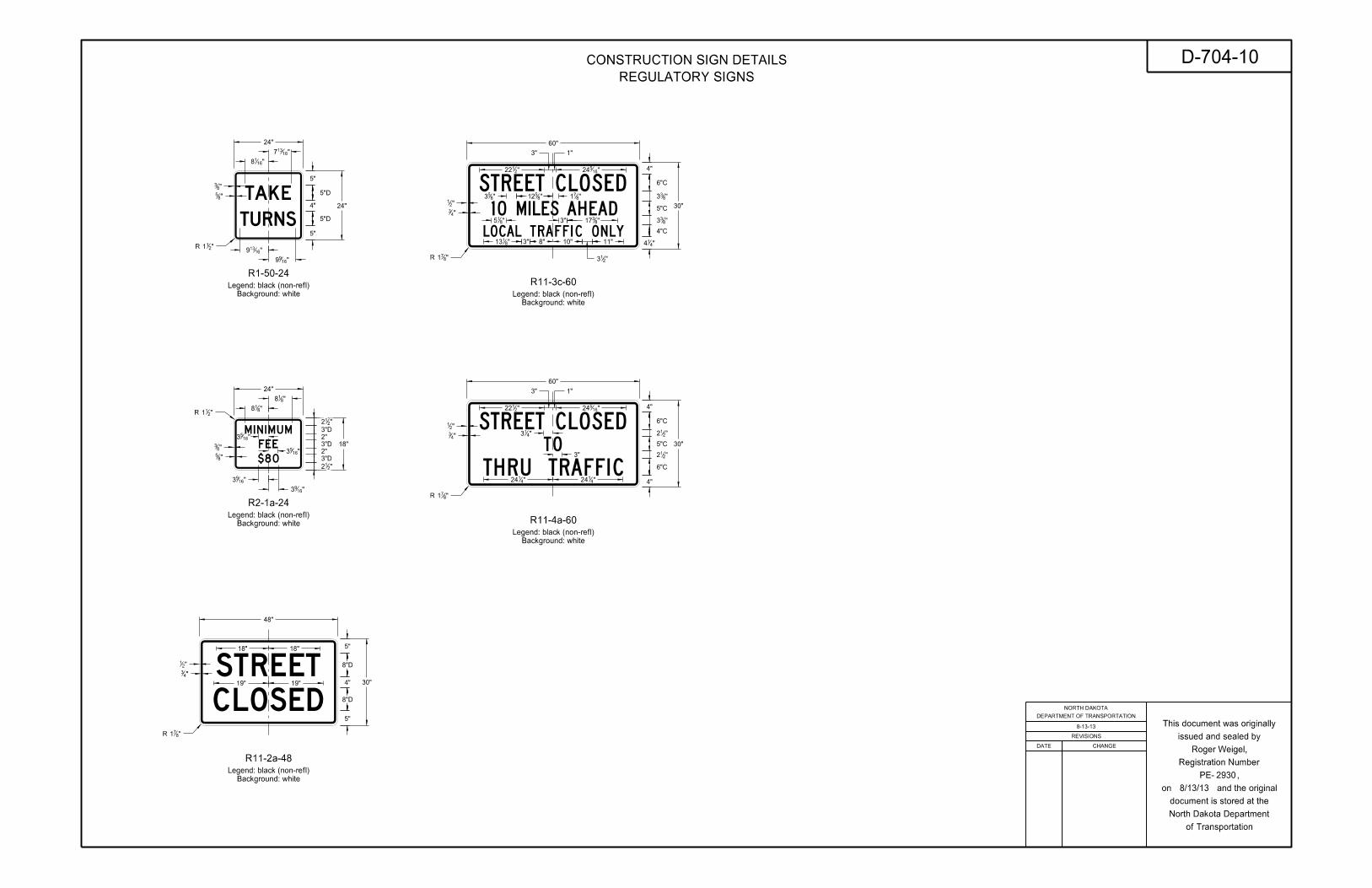
R2-1a-24
Background: white
Legend: black (non-refl)
18"18"
19"19"
48"
30"
"21
"43
5"
4"
5"
Background: white
Legend: black (non-refl)
R11-2a-48
Background: white
Legend: black (non-refl)
R11-4a-60
30"
60"
"871R
"2122 "16
524
1"3"
"413
3"
"4124"4
124
"21
"43
"871R
4"
"212
"212
4"
6"C
6"C
5"C
8"D
8"D
Background: white
Legend: black (non-refl)
60"
1"3"
"2122 "16
524
"43
"21
"871R
3""815
R11-3c-60
Background: white
Legend: black (non-refl)
30"
4"
"833
"833
"414
4"C
6"C
5"C
"8512"8
53 "871
"8317
"8113 3" 10"8" 11"
"213
24"
5"
5"
5"D
5"D
24"
4"
"1618
"16137
"83
"85
"16139
"1699
R1-50-24
"211R
"818
"818
18"
"1653
"1653
"1693
"83
"85
24"
"212
"212
"1693
"211R
3"D
2"
3"D
2"
3"D
REVISIONS
DATE CHANGE
DEPARTMENT OF TRANSPORTATION
NORTH DAKOTA
of Transportation
North Dakota Department
document is stored at the
on and the original
PE- ,
Registration Number
issued and sealed by
This document was originally8-13-13
D-704-10
2930
CONSTRUCTION SIGN DETAILS
REGULATORY SIGNS
Roger Weigel,
8/13/13
TUBULAR MARKERVERTICAL PANEL
28" min
8" to 12"
4"
4"
TRAFFIC CONE
2" min
4" to 6"
36" min
18" min
DELINEATOR DRUM
6"
3" to 4"
28" min
2"
4"
4" to 6"
More than 36"
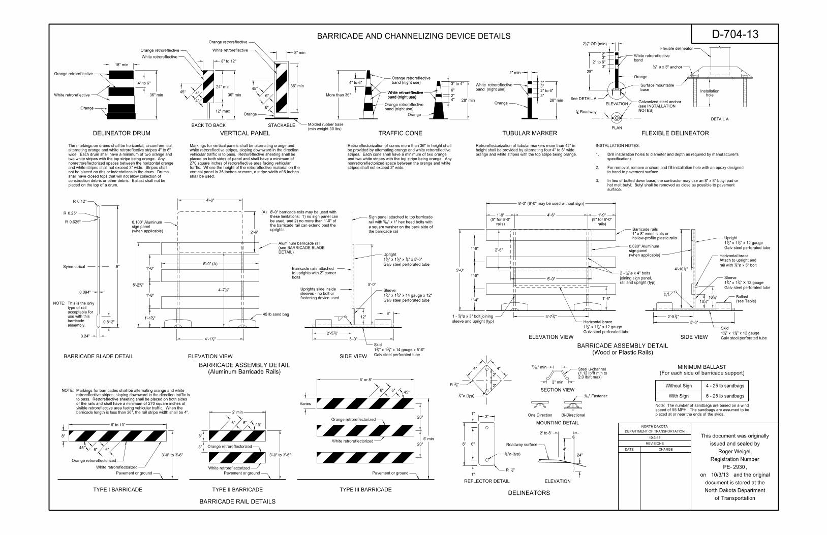
stripes shall not exceed 3" wide.
nonretroreflectorized space between the orange and white
and two white stripes with the top stripe being orange. Any
stripes. Each cone shall have a minimum of two orange
be provided by alternating orange and white retroreflective
Retroreflectorization of cones more than 36" in height shall
6" 6"
6’ to 10’
8"
3’-0" to 3’-6"
45°
2’ min
3’-0" to 3’-6"
45°
8"
8"
6" 6"45°
5’ min
20"
20"
Varies
2" to 6"
3"
3"2"
45°
White retroreflective
Orange retroreflective
Orange retroreflective
Orange
White retroreflective
Orange
band (night use)
White retroreflective
band (night use)
Orange retroreflective
band (night use)
White retroreflective
White retroreflectorized
Orange retroreflectorized
White retroreflectorized
Orange retroreflectorized
band (night use)
White retroreflective
band (night use)
Orange retroreflective
Orange retroreflectorized
White retroreflectorized
3"
3"
28"
2"
PLAN
ELEVATION
DETAIL A
FLEXIBLE DELINEATOR
"435’-2
"214’-1 5’-0"
12"
5’-0"
8"
"214’-7
2" to 6"
6’ or 8’
(Aluminum Barricade Rails)
BARRICADE ASSEMBLY DETAIL
1’-8"
1’-8"
"431’-1 "4
34’-7
5’-0"
1’-8"
1’-8"
1’-4" 1’-6"
SIDE VIEW
SIDE VIEW
(Wood or Plastic Rails)
BARRICADE ASSEMBLY DETAIL
5’-0"
Orange
‘ Roadway
band
White retroreflective
base
Surface mountable
45 lb sand bag
DETAIL)
(see BARRICADE BLADE
Aluminum barricade rail
hollow-profile plastic rails
1" x 8" wood slats or
Barricade rails
fastening device used
sleeves - no bolt or
Uprights slide inside
bolts
to uprights with 2" corner
Barricade rails attached
"41
Galv steel perforated tube
" x 14 gauge x 12"43" x 14
31
Sleeve
the barricade rail
a square washer on the back side of
" x 1" hex head bolts with 165rail with
Sign panel attached to top barricade
rail and upright (typ)
joining sign panel,
"| x 4" bolts 832 -
sleeve and upright (typ)
"| x 3" bolt joining 831 -
Galv steel perforated tube
" x 5’-0"81" x 2
1" x 1211
Upright
Galv steel perforated tube
" x 14 gauge x 5’-0"43" x 14
31
Skid
"4110
"4116
"| x 5" bolt83rail with
Attach to upright and
Horizontal brace
Galv steel perforated tube
" X 12 gauge43" x 14
31
Sleeve
Galv steel perforated tube
" x 12 gauge21" x 12
11
Upright
Galv steel perforated tube
" x 12 gauge43" x 14
31
SkidGalv steel perforated tube
" x 12 gauge21" x 12
11
Horizontal brace
ELEVATION VIEW
ELEVATION VIEW
"414’-10
Flexible delineator
See DETAIL A
Pavement or ground Pavement or ground Pavement or ground
" OD (min)412
6" 6"
rails)
(9" for 6’-0"
rails)
(9" for 6’-0"
1’-9"4’-6"1’-9"
Orange
STACKABLEBACK TO BACK
36" min
12" max
24" min 36" min
Orange retroreflective
White retroreflective
6"
6"
45°
Orange
(min weight 30 lbs)
Molded rubber base
placed on the top of a drum.
construction debris or other debris. Ballast shall not be
shall have closed tops that will not allow collection of
not be placed on ribs or indentations in the drum. Drums
and white stripes shall not exceed 3" wide. Stripes shall
nonretroreflectorized spaces between the horizontal orange
two white stripes with the top stripe being orange. Any
wide. Each drum shall have a minimum of two orange and
alternating orange and white retroreflective stripes 4" to 6"
The markings on drums shall be horizontal, circumferential,
" | x 3" anchor83
NOTES)
(see INSTALLATION
Galvanized steel anchor
holeInstallation
4’-0"
2’-6"
5’-0"
2’-6"
surface.
hot melt butyl. Butyl shall be removed as close as possible to pavement
In lieu of bolted down base, the contractor may use an 8" x 8" butyl pad or 3.
to bond to pavement surface.
For removal, remove anchors and fill installation hole with an epoxy designed 2.
specifications.
Drill installation holes to diameter and depth as required by manufacturer’s 1.
INSTALLATION NOTES:
shall be used.
vertical panel is 36 inches or more, a stripe width of 6 inches
Where the height of the retroreflective material on the traffic.
270 square inches of retroreflective area facing vehicular
placed on both sides of panel and shall have a minimum of
vehicular traffic is to pass. Retroreflective sheeting shall be
white retroreflective stripes, sloping downward in the direction
Markings for vertical panels shall be alternating orange and
orange and white stripes with the top stripe being orange.
height shall be provided by alternating four 4" to 6" wide
Retroreflectorization of tubular markers more than 42" in
8" min
Symmetrical
0.812"
0.24"
9"
0.094"
0.625"R
0.12"R
0.25"R
BARRICADE BLADE DETAIL
4" 4"
2"
6"
1"
1"
8"
3"
"83R
"21R
"| (typ)41
"| (typ)41
2"
SECTION VIEW
" min1611
One Direction Bi-Directional
" Fastener163
2" min
MOUNTING DETAIL
DELINEATORS
ELEVATION
4’
REFLECTOR DETAIL
barricade length is less than 36", the rail stripe width shall be 4".
visible retroreflective area facing vehicular traffic. When the
of the rails and shall have a minimum of 270 square inches of
to pass. Retroreflective sheeting shall be placed on both sides
retroreflective stripes, sloping downward in the direction traffic is
Markings for barricades shall be alternating orange and white NOTE:
Roadway surface
24"
2’ to 8’
TYPE I BARRICADE TYPE II BARRICADE TYPE III BARRICADE
BARRICADE RAIL DETAILS
6’-0" (A)
uprights.
the barricade rail can extend past the
be used, and 2) no more than 1’-0" of
these limitations: 1) no sign panel can
8’-0" barricade rails may be used with (A)
assembly.
barricade
use with this
acceptable for
type of rail
This is the only NOTE:
8’-0" (6’-0" may be used without sign)
2.0 lb/ft max)(1.12 lb/ft min to Steel u-channel
(when applicable)
sign panel
0.100" Aluminum
(when applicable)
sign panel
0.080" Aluminum
"812’-5
"812’-5
placed at or near the ends of the skids.
speed of 55 MPH. The sandbags are assumed to be
Note: The number of sandbags are based on a wind
With Sign
Without Sign 4 - 25 lb sandbags
6 - 25 lb sandbags
(see Table)
Ballast
(For each side of barricade support)
MINIMUM BALLAST
10-3-13
D-704-13
2930
BARRICADE AND CHANNELIZING DEVICE DETAILS
REVISIONS
DATE CHANGE
DEPARTMENT OF TRANSPORTATION
NORTH DAKOTA
of Transportation
North Dakota Department
document is stored at the
on and the original
PE- ,
Registration Number
issued and sealed by
This document was originally
Roger Weigel,
10/3/13
15"
48" 48"
16"
16"
12"
6’ min
shoulder
Edge of finished
lane
Edge of driving
6’ to 16’
(secondary sign)Vertical clearance
(main sign)Vertical clearance
15"
48" 48"
16"
16"
18"
18"
6"
12"
4"
(urban areas)
Orange flags
3" 21"
60"
60"
24"
12"
12"
12"
15" 15"24"3"
3"
18"
54"
48"
12"
24"
12"
12" 12"24"
9"
12" 24" 12"
48"
12"
24"
18"
3"
3"
10"
20"
20"
10"
60"15"
30"3"
3"
24"
16"
16"
48"
15"
48"
12"
W16-2P-30
24"
30"
3"3"
3"
24"
3"
21"
18"
supports
Extend
48"
15"
15"
18"
30"3"
12"
24"15"
54"
15"
6"24"
24"
30"
3"3"
30"
3"
21"
24"
3"
48"
24" 12"12"
12"
24"
12"
48"
9"
3"
3"
24"
24"
54"
15" 15"24"3"
3"
18"
12"
24"
12"
48"supports
Extend
64"
24"12" 12"
6" 6"32"32"32"
108"
48"
16" 16"
96"
32"32"
12" 12"
72"
36"
24"24"
12" 12"
72"
24"24"
24"
12" 12"
60"
36" 12" 12"
48"
24"
"211
"211
"211
"21
12"
12"
"211
3"3" 24" "2
1
15"
"211
"211
12"
24"
"2110
21"
21"
36"
18"
18"
36"
18"3"
3"
3"
3"
6"
6"3"
3"
30"
15"
(48" x 48" diamond warning sign shown)
TYPICAL SECTION
R1-2-60 - YIELD SIGN
30" x 24" SIGN
(with R6-1-54 sign as required)
R1-1-48 - STOP SIGN
(with R6-1-54 sign as required)
48" x 48" SIGN
(with R1-50-24 sign as required)
R1-1-48 - STOP SIGN
(with R2-1a-24 sign as required)
48" x 48" SIGNW14-3-64 - PENNANT SIGN
12"
(with 30" x 24" secondary sign)
48" x 48" DIAMOND SIGN
(with 30" x 30" secondary sign)
48" x 48" DIAMOND SIGN
DIAMOND SIGN
18" x 18"
108" x 48" SIGN 96" x 48" SIGN 72" x 36" SIGN 72" x 24" SIGN 60" x 24" SIGN 48" x 24" SIGN
18" 18"
24"3"
3"
36"
12"
24" x 36" SIGN
ASSEMBLY
ROUTE MARKER
24" x 24"
ASSEMBLY
ROUTE MARKER
36" x 36"
"4334
(secondary sign)Vertical clearance
(main sign)Vertical clearance
(main sign)Vertical clearance
W13-1P-30
(main sign)Vertical clearance (main sign)
Vertical clearance
(main sign)Vertical clearance
(main sign)Vertical clearance
(main sign)Vertical clearance
(main sign)Vertical clearance
(secondary sign)Vertical clearance
(main sign)Vertical clearance
(secondary sign)Vertical clearance (main sign)
Vertical clearance
(secondary sign)Vertical clearance
3"
24"
6"4"
20"
20"
4"
20"
20"
18"
(main sign)Vertical clearance
(main sign)Vertical clearance
(main sign)Vertical clearance
(main sign)Vertical clearance
(main sign)Vertical clearance
(main sign)Vertical clearance
(main sign)Vertical clearance
48"
24"
(main sign)Vertical clearance
24"
(main sign)Vertical clearance3"
18"
3"
18"
9""2
118"4
1
" plywood sign panel21
0.080" aluminum or
panel and supports
bolt (2 per support) joining sign
" A325 or equivalent 21"| x 316
5
"| x 5" bolt165with
Attach to upright
Horizontal brace
(ft)
Mounting Height
Sign Panel
4’ x 4’ sign panel
sandbags for
Number of 25 lb
5’
7’ 10
(see Table)
Ballast
8
32"
9"
48"
panel and supports
bolt (2 per support) joining sign
"| x 3" A325 or equivalent 165
"41
(see Table)
Ballast
" plywood sign panel21
0.080" aluminum or
upright and sleeve
equivalent bolt joining
"| x 3" A325 or 165
(optional)
upright and sleeve
equivalent bolt joining
"| x 3" A325 or 165
72"
"8123
61’
HIGH-MOUNTING HEIGHT
PORTABLE SIGN SUPPORT
required)
(when
R6-1-54
required)
(when
W20-52-54
required)
(when
R2-1a-24required)
(when
R1-50-24
LOW-MOUNTING HEIGHT
PORTABLE SIGN SUPPORT
" x 10 gauge21" x 22
12
Use minimum post size of
Steel perforated tube support
Steel perforated tube
" x 12 gauge21" x 344
1" x 2412
Horizontal brace
Steel perforated tube
" x 12 gauge21" x 22
12
Sleeve
Steel perforated tube
" x 12 gauge21" x 22
12
Skid
Steel perforated tube
" x 12 gauge43" x 14
31
Sleeve
Steel perforated tube
" x 12 gauge43" x 14
31
Skid
Steel perforated tube
" x 12 gauge43" x 14
31
Upright
(For each side of sign support base)
MINIMUM BALLAST
placed at or near the ends of the skids.
speed of 55 MPH. The sandbags are assumed to be
Note: The number of sandbags are based on a wind
curb to the near edge of the sign.
clearance of 2’ from the face of the
curb shall have a minimum horizontal
Note: Signs placed in sections with
78" max
12" min
32"
Steel perforated tube
" x 12 gauge41" x 24
12
Upright
clearancevertical
minimum5’ or 7’
clearance
vertical
for 7’
150" min
or
for 5’
126" min
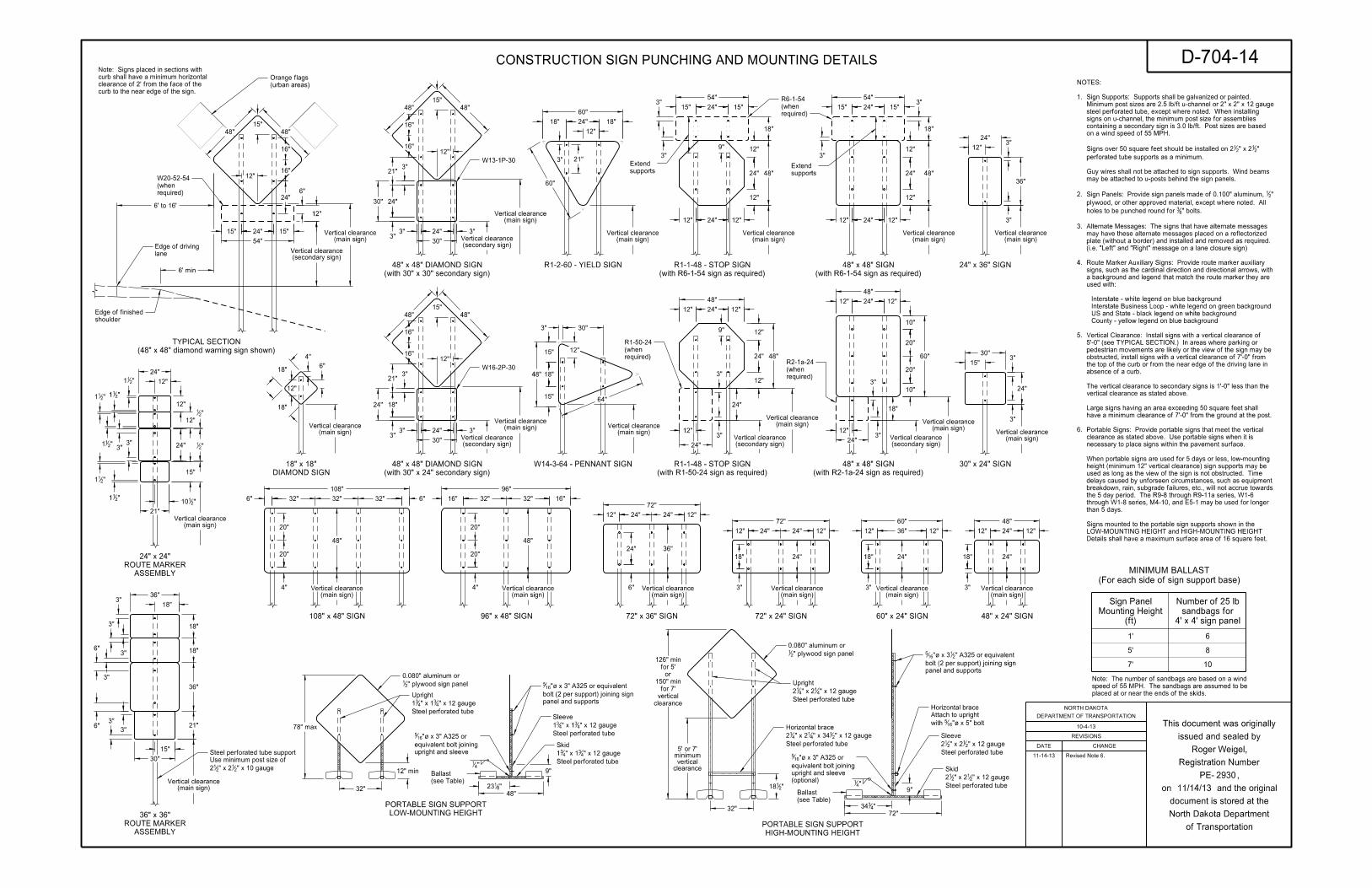
Details shall have a maximum surface area of 16 square feet.
LOW-MOUNTING HEIGHT and HIGH-MOUNTING HEIGHT
Signs mounted to the portable sign supports shown in the
than 5 days.
through W1-8 series, M4-10, and E5-1 may be used for longer
the 5 day period. The R9-8 through R9-11a series, W1-6
breakdown, rain, subgrade failures, etc., will not accrue towards
delays caused by unforseen circumstances, such as equipment
used as long as the view of the sign is not obstructed. Time
height (minimum 12" vertical clearance) sign supports may be
When portable signs are used for 5 days or less, low-mounting
necessary to place signs within the pavement surface.
clearance as stated above. Use portable signs when it is
Portable Signs: Provide portable signs that meet the vertical 6.
have a minimum clearance of 7’-0" from the ground at the post.
Large signs having an area exceeding 50 square feet shall
vertical clearance as stated above.
The vertical clearance to secondary signs is 1’-0" less than the
absence of a curb.
the top of the curb or from the near edge of the driving lane in
obstructed, install signs with a vertical clearance of 7’-0" from
pedestrian movements are likely or the view of the sign may be
5’-0" (see TYPICAL SECTION.) In areas where parking or
Vertical Clearance: Install signs with a vertical clearance of 5.
County - yellow legend on blue background
US and State - black legend on white background
Interstate Business Loop - white legend on green background
Interstate - white legend on blue background
used with:
a background and legend that match the route marker they are
signs, such as the cardinal direction and directional arrows, with
Route Marker Auxiliary Signs: Provide route marker auxiliary 4.
(i.e. "Left" and "Right" message on a lane closure sign)
plate (without a border) and installed and removed as required.
may have these alternate messages placed on a reflectorized
Alternate Messages: The signs that have alternate messages 3.
" bolts.83holes to be punched round for
plywood, or other approved material, except where noted. All
" 21Sign Panels: Provide sign panels made of 0.100" aluminum, 2.
may be attached to u-posts behind the sign panels.
Guy wires shall not be attached to sign supports. Wind beams
perforated tube supports as a minimum.
" 21" x 22
1Signs over 50 square feet should be installed on 2
on a wind speed of 55 MPH.
containing a secondary sign is 3.0 lb/ft. Post sizes are based
signs on u-channel, the minimum post size for assemblies
steel perforated tube, except where noted. When installing
Minimum post sizes are 2.5 lb/ft u-channel or 2" x 2" x 12 gauge
Sign Supports: Supports shall be galvanized or painted. 1.
NOTES:
10-4-13
D-704-14
11/14/13
2930
CONSTRUCTION SIGN PUNCHING AND MOUNTING DETAILS
Roger Weigel,
REVISIONS
DATE CHANGE
DEPARTMENT OF TRANSPORTATION
NORTH DAKOTA
of Transportation
North Dakota Department
document is stored at the
on and the original
PE- ,
Registration Number
issued and sealed by
This document was originally
11-14-13 Revised Note 6.
CLOSED
ROAD
DETOUR
ORTHN
DETOUR
XXX FT
CLOSED
ROAD
XXX FT
CLOSED
ROAD
XXX FT
XXXX FT
ROAD
WORK
SPEEDLIMIT
XX
SPEEDLIMIT
XX
XXXX FT
ONE LANE
ROAD
XXXX FT
ONE LANE
ROAD
XXX
FEET
XXX
FEET
SPEED LIMIT ENFORCED
MINIMUM FEE $80WHEN WORKERS PRESENT
SPEED LIMIT ENFORCED
MINIMUM FEE $80WHEN WORKERS PRESENT
END
ROAD WORK
END
ROAD WORK
SPEED
XXLIMIT
SPEED
XXLIMIT
SPEED
XXLIMIT
SPEED
XXLIMIT
MINIMUM
FEE
$80
MINIMUM
FEE
$80
XX
XX
DETOUR
XX
DETOUR
LOCAL TRAFFIC ONLY
ROAD CLOSED
MILES AHEADXX
DETOUR
XXXX FT
ROAD
WORK
KEY
Drum
Delineator
Sign
Barricade
Type III Flagger
Area
Work/Hazard
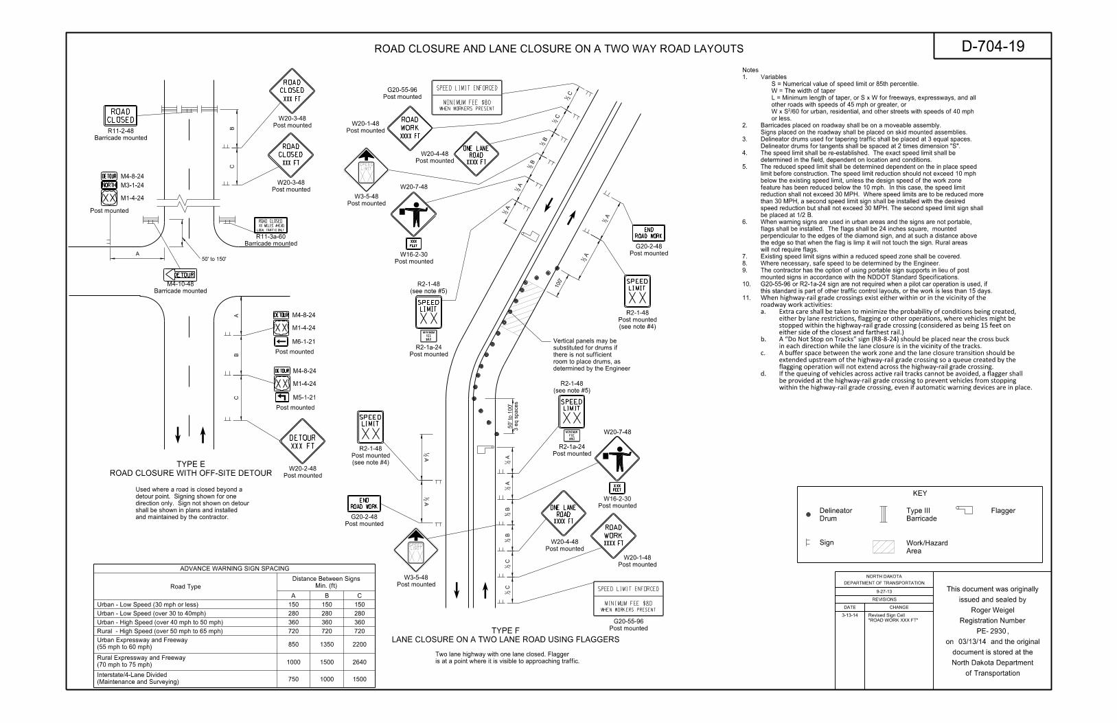
ADVANCE WARNING SIGN SPACING
Road Type Min. (ft)
Distance Between Signs
A B C
150 150 150
280 280 280
360 360 360
720 720 720
850 1350 2200
1000 1500 2640
750 1000 1500
Urban - Low Speed (30 mph or less)
Urban - Low Speed (over 30 to 40mph)
Urban - High Speed (over 40 mph to 50 mph)
Rural - High Speed (over 50 mph to 65 mph)
(55 mph to 60 mph)
Urban Expressway and Freeway
(70 mph to 75 mph)
Rural Expressway and Freeway
(Maintenance and Surveying)
Interstate/4-Lane Divided
Barricade mounted
R11-2-48
M4-8-24
M3-1-24
M1-4-24
Post mounted
Post mounted
W20-3-48
Post mounted
W20-3-48
M4-8-24
M1-4-24
M6-1-21
Post mounted
Post mounted
W20-2-48
Post mounted
G20-55-96
Post mounted
W20-1-48
Post mounted
W20-4-48
Post mounted
W3-5-48
Post mounted
R2-1a-24
(see note #4)
Post mounted
R2-1-48
Post mounted
W3-5-48
Post mounted
G20-55-96
Post mounted
W20-1-48
Post mounted
W20-4-48
Post mounted
R2-1a-24
and maintained by the contractor.
shall be shown in plans and installed
direction only. Sign not shown on detour
detour point. Signing shown for one
Used where a road is closed beyond a
is at a point where it is visible to approaching traffic.
Two lane highway with one lane closed. Flagger
determined by the Engineer
room to place drums, as
there is not sufficient
substituted for drums if
Vertical panels may be
M4-8-24
M1-4-24
Post mounted
M5-1-21
50’ to 150’
BB
AC
C
A
C2
1 C
21
B2
1 B
21
A2
1 A
21
3 e
q s
paces
50’ to 1
00’
A2
1 A
21
100’
A21
A21
A21
A21
B21
B21
C21
C21
Barricade mounted
M4-10-48
Barricade mounted
R11-3a-60
W20-7-48
Post mounted
W16-2-30 Post mounted
G20-2-48
Post mounted
G20-2-48
W20-7-48
Post mounted
W16-2-30
ROAD CLOSURE WITH OFF-SITE DETOUR
TYPE E
LANE CLOSURE ON A TWO LANE ROAD USING FLAGGERS
TYPE F
(see note #5)
R2-1-48
(see note #4)
Post mounted
R2-1-48
(see note #5)
R2-1-48
within the highway-rail grade crossing, even if automatic warning devices are in place.
be provided at the highway-rail grade crossing to prevent vehicles from stopping
If the queuing of vehicles across active rail tracks cannot be avoided, a flagger shalld.
flagging operation will not extend across the highway-rail grade crossing.
extended upstream of the highway-rail grade crossing so a queue created by the
A buffer space between the work zone and the lane closure transition should bec.
in each direction while the lane closure is in the vicinity of the tracks.
A �Do Not Stop on Tracks� sign (R8-8-24) should be placed near the cross buckb.
either side of the closest and farthest rail.)
stopped within the highway-rail grade crossing (considered as being 15 feet on
either by lane restrictions, flagging or other operations, where vehicles might be
Extra care shall be taken to minimize the probability of conditions being created,a.
roadway work activities:
When highway-rail grade crossings exist either within or in the vicinity of the11.
this standard is part of other traffic control layouts, or the work is less than 15 days.
G20-55-96 or R2-1a-24 sign are not required when a pilot car operation is used, if10.
mounted signs in accordance with the NDDOT Standard Specifications.
The contractor has the option of using portable sign supports in lieu of post9.
Where necessary, safe speed to be determined by the Engineer.8.
Existing speed limit signs within a reduced speed zone shall be covered.7.
will not require flags.
the edge so that when the flag is limp it will not touch the sign. Rural areas
perpendicular to the edges of the diamond sign, and at such a distance above
flags shall be installed. The flags shall be 24 inches square, mounted
When warning signs are used in urban areas and the signs are not portable, 6.
be placed at 1/2 B.
speed reduction but shall not exceed 30 MPH. The second speed limit sign shall
than 30 MPH, a second speed limit sign shall be installed with the desired
reduction shall not exceed 30 MPH. Where speed limits are to be reduced more
feature has been reduced below the 10 mph. In this case, the speed limit
below the existing speed limit, unless the design speed of the work zone
limit before construction. The speed limit reduction should not exceed 10 mph
The reduced speed limit shall be determined dependent on the in place speed 5.
determined in the field, dependent on location and conditions.
The speed limit shall be re-established. The exact speed limit shall be 4.
Delineator drums for tangents shall be spaced at 2 times dimension "S".
Delineator drums used for tapering traffic shall be placed at 3 equal spaces. 3.
Signs placed on the roadway shall be placed on skid mounted assemblies.
Barricades placed on roadway shall be on a moveable assembly.2.
or less.
W x SÔ/60 for urban, residential, and other streets with speeds of 40 mph
other roads with speeds of 45 mph or greater, or
L = Minimum length of taper, or S x W for freeways, expressways, and all
W = The width of taper
S = Numerical value of speed limit or 85th percentile.
Variables1.
Notes
3-13-14
"ROAD WORK XXX FT"
Revised Sign Cell
REVISIONS
DATE CHANGE
DEPARTMENT OF TRANSPORTATION
NORTH DAKOTA
of Transportation
North Dakota Department
document is stored at the
on and the original
PE- ,
Registration Number
issued and sealed by
This document was originally
D-704-19
03/13/14
2930
ROAD CLOSURE AND LANE CLOSURE ON A TWO WAY ROAD LAYOUTS
9-27-13
Roger Weigel

THICK.
GALV. END SECTION DIMENSIONS
IN
A
IN
B
IN
H
IN
L
IN
W
RATE
SLOPE
APPROX.
PIECE
BODY
*
*
*
DIA.
PIPE
IN
*
*
**
0.109
0.109
0.109
0.109
0.109
0.109
0.109
0.109
0.079
0.079
0.064
0.064
0.064
18
18
18
18
18
18
18
16
14
12
10
8
7
45
42
39
36
33
30
27
22
19
16
13
10
8
12
12
12
12
12
12
12
11
9
8
6
6
6
87
87
87
87
87
84
78
69
60
51
41
31
26
138
132
126
120
114
102
90
84
72
60
48
36
30
1 1/6 :1
1�:1
1 1/3 :1
1�:1
1�:1
2:1
2�:1
2�:1
2�:1
2�:1
2�:1
2�:1
2�:1
IN
3
3
3
3
3
2
2
2
2
1 or 2
1
1
1
84
78
72
66
60
54
48
42
36
30
24
18
15
D
7" for 36" & smaller diam, 12" for 42" thru 84" diam
A
A
L
A AW
8"
(12" max spacing)
" holes for bolts or rivets167
2"
A
A
H
Connecting band
L
(showing connector section)
PLAN VIEW
ELEVATION VIEW TYPICAL CROSS SECTION
SECTION A-A
"411
4" 2"4"
2"
2"
"432
C
CBB
"85 "8
5
"432
"43
"432
C
C
D
D
"322
2"
"217
"43
"43
1"
"2111
"43
1"
"322
"21
TYPE #1 TYPE #2 TYPE #3
diameter 24" & smaller
For circular pipes with
diameter 30" through 36"
For circular pipes withFor all pipe sizes
HAT BAND FOR FLANGED END PIPE
SIDE VIEW SECTION B-B
SECTIONAL VIEW
SIDE VIEW SECTION C-C
ANNULAR BAND Angle Connection
SIDE VIEW END VIEW
" Angle Connector1632" x 2" x Die-Formed Angle Connector
SIDE VIEW
HUGGER COUPLING BAND
SECTION D-D
Bar & Strap Connection
SPIRAL RIB CORRUGATIONS
"21" x 1" Rib @ 114
3"21" Rib @ 74
3" x 43
Re-Rolled Pipe End
Steel
Galvanized
" galv. bolts or rivets83
Corner plate
price bid for end sections.
plate, bolts, and nuts are to be included in
section. Where toe plate is required, the toe
Thickness of toe plate to be same as end
for pipe of 30" diameter or larger.
Galvanized toe plate required on end sections
slope
Variable
match slope of end section
If necessary, warp inslope to
Flow line
Connector
Flat Strap
or re-rolled helical
End of pipe, annular
Strap Bolt
or re-rolled helical
End of pipe, annular
Threaded rod
Rod Holder
end is attached
Pipe to which
" bolts83with
bolted to end section
Univeral Band Collar
" slots87" x 16
9
corrugation crest
Spot weld at each Band
"163
"43
thickness
Min .064" Reformed Ends
" x 6" bolt21
" x 6" bolt21
or Die-Formed Angle
" Angle1632" x 2" x
14" coupling band
3" spacing for
Connection
Single Bar & Strap
Spot Welds
when required
Joint SealantEnd Helical Pipe
Reformed Rolled
" x 6" bolt21
" CORRUGATIONS21" x 3
22
" x 6" bolts21
" x 6" bolts21
* *
*
See Note 6
Hugger Band
Annular Band
Hat Band
TYPE
COUPLING
PITCH x DEPTH
CORRUGATION
"21" x 3
22
"21" x 3
22
3" x 1"
Rerolled End
"21" x 3
22
Rerolled End
3" x 1"
COUPLING BAND DIMENSIONS
"432
"2110
"2110
torqued to 25 foot-lbs –.
" dia. galv. bolts or rivets. Nuts to be83tightly joined with
Multiple panel bodies shall have lap seams which are to be
Splices to be the lap riveted type.
Manufacturers tolerances of above dimensions will be allowed.
Pipe diameter is equal to dimension "D" of end section.
These sizes have 0.109" sides and 0.138" center panels.
2.
1.
4.
3.
5.
Coupling Band Length
Coupling Band Length
Coupling Band Length
Band Length
Coupling
6.
7.
12"
Pipe dia
For 78" - 120" pipe: 0.109" strap thickness
For 12" - 72" pipe: 0.079" strap thickness
Pipe
"2110
Rerolled End
5" x 1"48" - 120"
48" - 120"
78" - 84"
12" - 72"
48" - 120"
78" - 84"
12" - 72"
12" - 48"
PIPE SIZE
12"
14"
12"
12"
BAND LENGTH
COUPLING
.064"
.052"
.079"
.052"
.052"
.079"
.052"
.064"
THICKNESS
MIN. BAND
SECTIONAL VIEW
2"4"4"
2"
"411
SIDE VIEW END VIEW
corrugation crest
Spot weld at each
Band"4
3
galv. steel
0.109" thick
" slots87" x 16
9 "165
14" coupling band
3" spacing for
See Note 6
Coupling Band Length
"83
"83
2"
1"
See Detail A
Detail A
Die-Formed Angle Connector
TOP VIEW
2"
"1692" 1""16
5
2"
(see Section A-A)
Rolled Edge for Reinforcement
".21Length of spot welds shall be minimum
" are used for the connection.21
5
" bolts with maximum spacing of21minimum of four
Coupling bands wider than 14" may be used if a
" x 6" bolts shown in the details.21
" x 8" bolts may be used as a substitute for the21
pipes 36" and smaller, a one-piece band is acceptable.
36" as shown in Section C-C & D-D details. For
Coupling bands shall be two-piece for pipes larger than
horizontal diameter 5% less than a circular pipe.
vertical diameter shall be 5% greater and the
Elongated pipes shall be factory preformed so that the
pipe to the corner wing bend.
" dia. bolts and nuts. Angles are to extend from83galv.
angle for 78" and 84" dia.. Angles to be attached by
" galv. 41" x 2
1" x 221for 60" through 72" dia. and 2
" galv. angle 41are to be supplemented with 2" x 2" x
reinforcement (see Section A-A). The reinforced edges
Top edge of all end sections to have rolled edges for
AASHTO M-36.
sections of NDDOT Standard Specifications and to
Pipes and connecting bands shall conform to applicable
NOTES:
Rolled Edge
End Section Plan View01-07-14
02-27-14 3" x 1" Corrugation Detail3" or 5"
5" x 1" CORRUGATIONS
3" x 1" CORRUGATIONS or
REVISIONS
DATE CHANGE
DEPARTMENT OF TRANSPORTATION
NORTH DAKOTA
of Transportation
North Dakota Department
document is stored at the
on and the original
PE- ,
Registration Number
issued and sealed by
This document was originally
Terrence R. Udland,
02/27/2014
2674
08-06-13
D-714-4ROUND CORRUGATED STEEL PIPE CULVERTS AND END SECTIONS
Sign overhang
widthFinished shoulder
spacingSign support
Sig
n s
upport
Anchor unit
Vertical cleara
nce
Sig
n h
eig
ht
below top of signDistance support
‘ of roadwayor auxiliary lane
Edge of driving lane
shoulder
Edge of finished
Foreslope
for number of supports required
see sign summary sheet
Second support,
for number of supports required
see sign summary sheet
Second support,
‘ of roadway
Foreslope
Sign overhang
below top of signDistance support
Anchor unit
Sig
n s
upport
7’ Vertical cleara
nce
Sig
n h
eig
ht
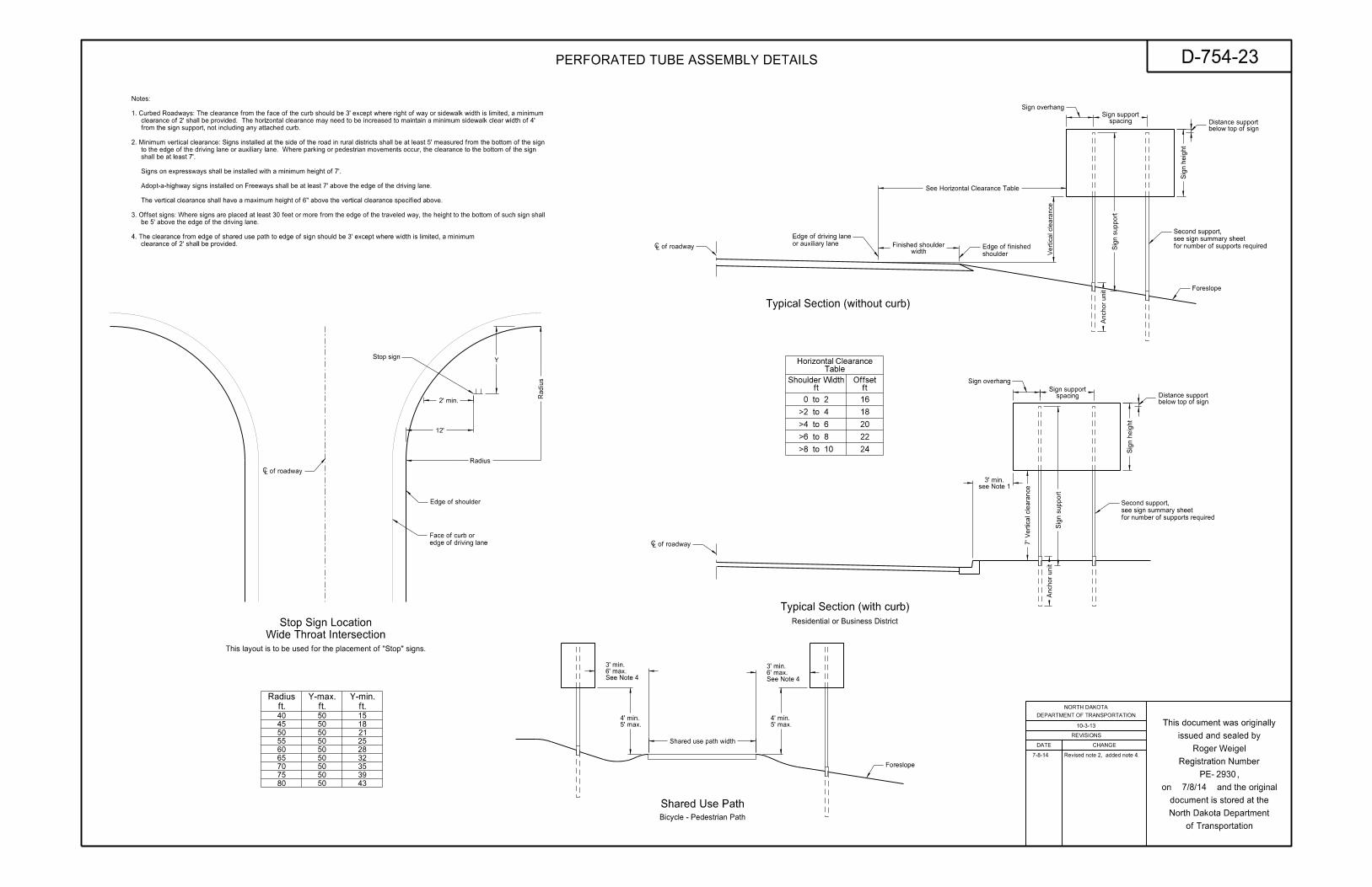
Shared use path width
5’ max.4’ min.
5’ max.4’ min.
Stop sign
12’
Y
2’ min.
edge of driving lane
Face of curb or
‘ of roadway
Radius
Radius
80
75
70
65
60
55
50
45
40
50
50
50
50
50
50
50
50
50
43
39
35
32
28
25
21
18
15
ft.
Radius
ft.
Y-max.
ft.
Y-min.
Residential or Business District
Bicycle - Pedestrian Path
This layout is to be used for the placement of "Stop" signs.
see Note 13’ min.
spacingSign support
0 to 2
>2 to 4
>4 to 6
>6 to 8
>8 to 10 24
22
20
18
16
TableHorizontal Clearance
ftShoulder Width
ftOffset
See Horizontal Clearance Table
Edge of shoulder
See Note 46’ max.3’ min.
See Note 46’ max.3’ min.
clearance of 2’ shall be provided.
4. The clearance from edge of shared use path to edge of sign should be 3’ except where width is limited, a minimum
be 5’ above the edge of the driving lane.
3. Offset signs: Where signs are placed at least 30 feet or more from the edge of the traveled way, the height to the bottom of such sign shall
The vertical clearance shall have a maximum height of 6" above the vertical clearance specified above.
Adopt-a-highway signs installed on Freeways shall be at least 7’ above the edge of the driving lane.
Signs on expressways shall be installed with a minimum height of 7’.
shall be at least 7’.
to the edge of the driving lane or auxiliary lane. Where parking or pedestrian movements occur, the clearance to the bottom of the sign
2. Minimum vertical clearance: Signs installed at the side of the road in rural districts shall be at least 5’ measured from the bottom of the sign
from the sign support, not including any attached curb.
clearance of 2’ shall be provided. The horizontal clearance may need to be increased to maintain a minimum sidewalk clear width of 4’
1. Curbed Roadways: The clearance from the face of the curb should be 3’ except where right of way or sidewalk width is limited, a minimum
Notes:
D-754-23
REVISIONS
DATE CHANGE
DEPARTMENT OF TRANSPORTATION
NORTH DAKOTA
of Transportation
North Dakota Department
document is stored at the
on and the original
PE- ,
Registration Number
issued and sealed by
This document was originally
PERFORATED TUBE ASSEMBLY DETAILS
Wide Throat Intersection
Stop Sign Location
Shared Use Path
Typical Section (with curb)
Typical Section (without curb)
10-3-13
7/8/14
2930
Roger Weigel 7-8-14 Revised note 2, added note 4.
30"
15"
3"
30"
3"
support
Sign
12"
16"
9" 9"
18"
36"
36"
6"9"
9"
22"
9" 18" 9"
28"
12" 12"6" 6"
24"
18" 18"
48"
9"12"
48"
12"
40"
12" 24" 12" 6" 18" 18" 6"
36"
3"
21"
36"
18"22"
18" 9"9"
8"
12"
40" 40"
48"
24"
3"
24"
48"
17"
38"
17"
6"
12"
8"
38"
28"
12" 24" 12" 7" 17" 17" 7"
38"
supports
Sign
Strin
gers
support
Sign
Strin
gerss
supports
Sign supports
Sign
n
n
support
Sign
supports
Sign
Strin
gers s
supports
Signn
Strin
gerss
supports
Signn
Sign support
Strin
gerss
sStrin
gers
support
Signsupports
Signn
supports
Sign
Strin
gerss
n
Strin
gers
Strin
gerss
s
n
s
Stringer Stringer
Stringer
Stringer
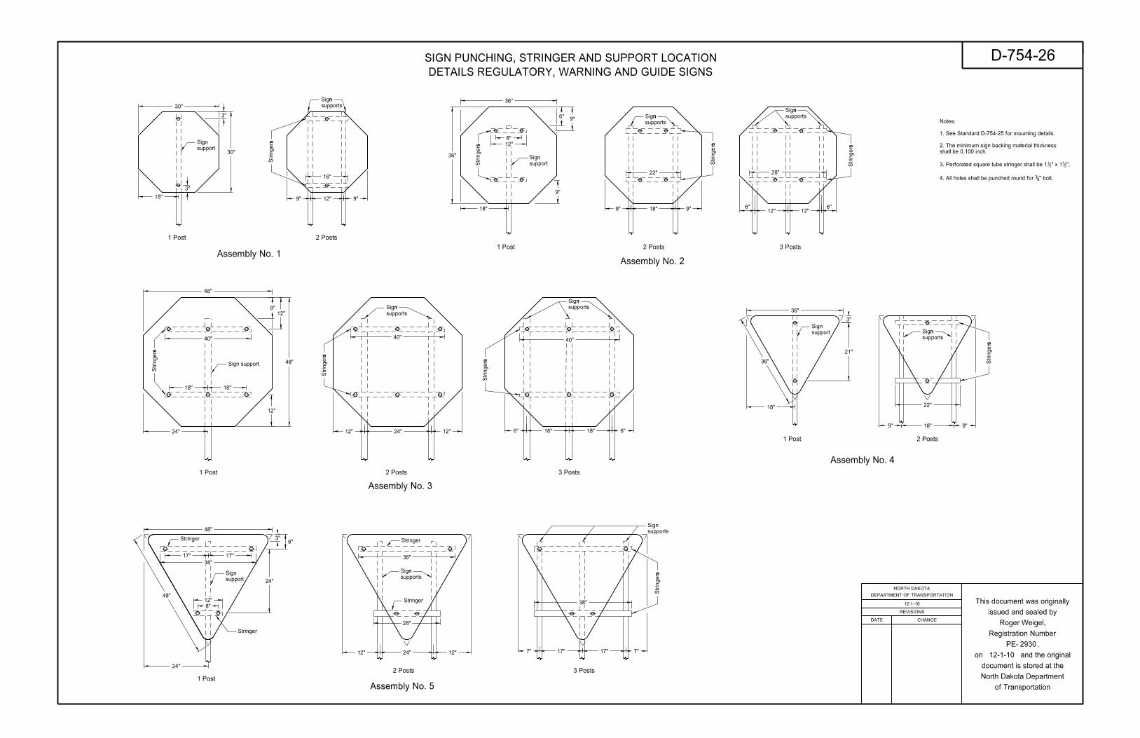
Assembly No. 1Assembly No. 2
Assembly No. 3
Assembly No. 4
Assembly No. 5
1 Post
1 Post
1 Post
1 Post
1 Post
2 Posts
2 Posts
2 Posts
2 Posts
2 Posts
3 Posts
3 Posts
3 Posts
REVISIONS
DATE CHANGE
DEPARTMENT OF TRANSPORTATION
NORTH DAKOTA
of Transportation
North Dakota Department
document is stored at the
on and the original
PE- ,
Registration Number
issued and sealed by
This document was originally
D-754-26
2930
SIGN PUNCHING, STRINGER AND SUPPORT LOCATION
" bolt.834. All holes shall be punched round for
".21" x 12
13. Perforated square tube stringer shall be 1
shall be 0.100 inch.
2. The minimum sign backing material thickness
1. See Standard D-754-25 for mounting details.
Notes:
DETAILS REGULATORY, WARNING AND GUIDE SIGNS
Roger Weigel,
12-1-10
12-1-10


