Aalborg Universitet Velocity Distribution in the Flow from a Wall-Mounted Diffuser in Rooms with Displacement Ventilation Nielsen, Peter V. Publication date: 1992 Document Version Publisher's PDF, also known as Version of record Link to publication from Aalborg University Citation for published version (APA): Nielsen, P. V. (1992). Velocity Distribution in the Flow from a Wall-Mounted Diffuser in Rooms with Displacement Ventilation. Dept. of Building Technology and Structural Engineering, Aalborg University. Indoor Environmental Technology Vol. R9252 No. 27 General rights Copyright and moral rights for the publications made accessible in the public portal are retained by the authors and/or other copyright owners and it is a condition of accessing publications that users recognise and abide by the legal requirements associated with these rights. - Users may download and print one copy of any publication from the public portal for the purpose of private study or research. - You may not further distribute the material or use it for any profit-making activity or commercial gain - You may freely distribute the URL identifying the publication in the public portal - Take down policy If you believe that this document breaches copyright please contact us at [email protected] providing details, and we will remove access to the work immediately and investigate your claim. Downloaded from vbn.aau.dk on: February 09, 2022
Transcript
Aalborg Universitet
Velocity Distribution in the Flow from a Wall-Mounted Diffuser in Rooms withDisplacement Ventilation
Nielsen, Peter V.
Publication date:1992
Document VersionPublisher's PDF, also known as Version of record
Link to publication from Aalborg University
Citation for published version (APA):Nielsen, P. V. (1992). Velocity Distribution in the Flow from a Wall-Mounted Diffuser in Rooms withDisplacement Ventilation. Dept. of Building Technology and Structural Engineering, Aalborg University. IndoorEnvironmental Technology Vol. R9252 No. 27
General rightsCopyright and moral rights for the publications made accessible in the public portal are retained by the authors and/or other copyright ownersand it is a condition of accessing publications that users recognise and abide by the legal requirements associated with these rights.
- Users may download and print one copy of any publication from the public portal for the purpose of private study or research. - You may not further distribute the material or use it for any profit-making activity or commercial gain - You may freely distribute the URL identifying the publication in the public portal -
Take down policyIf you believe that this document breaches copyright please contact us at [email protected] providing details, and we will remove access tothe work immediately and investigate your claim.
INSTITUTTET FOR BYGNINGSTEKNIK . DEPT. OF BUILDING TECHNOLOGY AND STRUCTURAL ENGINEERING AALBORG UNIVERSITETSCENTER • AUC • AALBORG • DANMARK
INDOOR ENVIRONMENTAL TECHNOLOGY PAPER NO. 27
Presented at ROOMVENT'92, Third I nt . Conf. on Air Distribution in Rooms, Aalborg, Denmar k, September 1992
P. V. NIELSEN VELOCITY DISTRIBUTION IN THE FLOW FROM A WALL-MOUNTED DIFFUSER IN ROOMS WITH DISPLACEMENT VENTILATION SEPTEMBER 1992 ISSN 0902-7513 R9252
The papers on INDOOR ENVIRONMENTAL TECHNOLOGY are issued for early dissemination of research results from the Indoor Environmental Technology Group at the University of Aalborg. These papers are generally submitted to scientific meetings, conferences or journals and should therefore not be widely distributed. Whenever possible reference should be given to the final publications (proceedings, journals, etc.) and not to the paper in this series.
J
I N STITUTTET F OR BYGN INGSTEKNIK DEPT. OF BUILDING TECHNOLOGY AND STRUCTURAL . ENGINEERING AALBORG UNIVERSITETSCENTER • AUC • AALBORG • DANMARK
INDOOR ENVIRONMENTAL TECHNOLOGY PAPER NO. 27
Presented at ROOMVENT'92, Third Int. Conf. on Air Distribution in Rooms, Aalborg, Denmark, September 1992
P. V. NIELSEN VELOCITY DISTRIBUTION IN THE FLOW FROM A WALL-MOUNTED DIFFUSER IN ROOMS WITH DISPLACEMENT VENTILATION SEPTEMBER 1992 ISSN 0902-7513 R9252
1
VEWCI'IY DISTRIBUTION IN THE FLOW FROM A WALL-MOUNTED DIFFUSER IN ROOMS
WITH DISPLACEMENT VENTILATION
Peter V. Nielsen Aalborg University, Denmark
SUMMARY
The paper describes experiments with wall-mounted air terminal devices. The airflow from an air terminal device will influence the thermal comfort of the occupants and it is therefore important to develop an expression for this flow. The velocity at the floor is influenced by the flow rate to the room, by the temperature difference and the type of diffuser. The flow is stratified at large temperature differences. The paper shows the development of an expression for the velocity distribution in the vicinity of the floor. It is shown that openings between obstacles placed directly on the floor will generate a flow similar to the air movement in front of a diffuser. An expression for the velocity distribution is given in the paper.
3
VELOCITY DISTRIBUTION IN THE FLOW FROM A WALL-MOUNTED DIFFUSER IN ROOMS
WITH DISPLACEMENT VENTILATION
Peter V. Nielsen Aalborg University, Denmark
INTRODUCTION
Ventilation systems with vertical displacement flow have been used in industrial areas with high thermal loads for many years. Quite recently the vertical displacement flow systems have grown popular as comfort ventilation in rooms with thermal loads, e.g. offices.
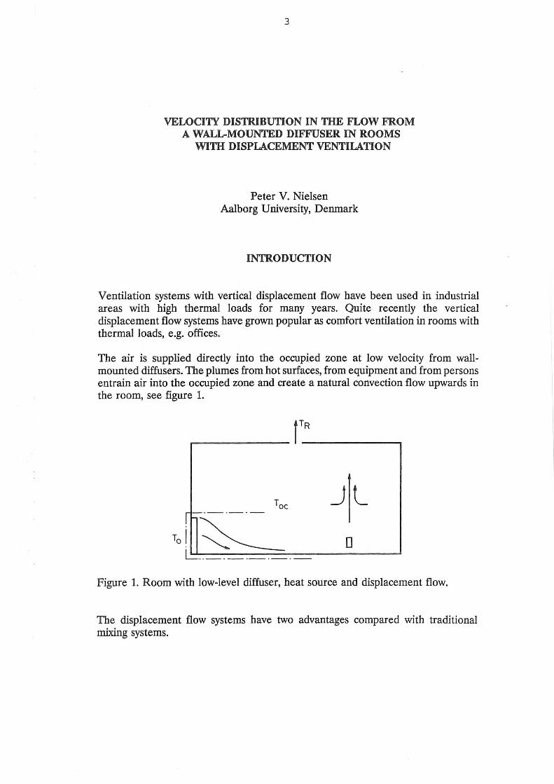
The air is supplied directly into the occupied zone at low velocity from wallmounted diffusers. The plumes from hot surfaces, from equipment and from persons entrain air into the occupied zone and create a natural convection flow upwards in the room, see figure 1.
~--------------iT_R--------------~
Jl loj~ ~----------
0
Figure 1. Room with low-level diffuser, heat source and displacement flow.
The displacement flow systems have two advantages compared with traditional mixing systems.
4
- An efficient use of energy. It is possible to remove exhaust air from the room where the temperature is several degrees above the temperature in the occupied zone which allows a higher air inlet temperature at the same load.
- An appropriate distribution of contaminated air. The vertical temperature gradient (or stratification) implies that fresh air and contaminated air are separated and the most contaminated air can be found above the occupied zone.
The design procedure for displacement ventilation deals with the velocity in front of a wall-mounted diffuser by defining the distance from the diffuser to an area where the velocity has decreased to 0.2 m/s (in many cases measured 0.1 m above the floor). The research described in this report is focused on the flow from wallmounted low velocity air terminal devices. It is the aim of the work to obtain results which can simplify and improve the practical design procedure.
- It is important to examine the flow in front of an air terminal device and to investigate if this flow can be treated unconnected with parameters as room geometry (generally speaking), heat source location and location of exhaust opening, etc.
The design procedure is simplified if the flow depends only on some main parameters as e.g. type of diffuser, obstacles on the floor, flow rate and Archimedes' number of the flow. It is especially a simplification if the influence of width and length of the horizontal section is small.
The expectation of this simplification is indicated in figure 1 by the dotted line. An equivalent situation is known in mixing ventilation where the flow from air terminal devices can be described relatively independent of the recirculating flow in the room.
- Furthermore, it is important to obtain a quantitative description of the flow along the floor. The flow along the floor in a room with buoyancy driven ventilation is the only air movement which influences the comfort of the occupants. A description of this air movement will therefore make it possible to obtain a detailed picture of the thermal comfort of the room which is a valuable information compared to the knowledge of distance to the 0.2 m's velocity level.
- One of the main problems in connection with computational fluid dynamics used for the prediction of room air movement is to obtain a practical description of the boundary conditions at the supply opening. Experimental work on the flow from diffusers may give important information which can be used for the individual description of different supply openings.
Large parts of the experiments described in this report are based on a number of research activities made at Aalborg University in connection with the education of M.Sc. students. The research activities are dated back to 1987 and the participating
5
students are mentioned in the reference list. All the experimental work has been supervised and tied together by the author who wants to use this opportunity to express his thanks to all participants.
WALL-MOUNTED LOW VELOCITY DIFFUSER
Figure 2 shows the wall-mounted low velocity diffusers which are tested and discussed in this paper. They are different products and they are designed for flow rates of 50 - 300 m3 /h, except diffuser type F which is designed for a flow rate of 500 - 1400 m3 /h.
A B D
E F G
Figure 2. Six different wall-mounted low velocity diffusers for displacement ventilation.
Diffuser type A has a supply velocity profile which is very constant over the entire supply area, while diffuser type B has a supply velocity with a large variation over the supply area both in speed and in direction, see reference [1 ].
Diffuser type D can be adjusted to two different modes. It can either work as a traditional diffuser, D1, or it can work with an internal induction unit, D2, which increases the flow rate at the diffuser surface with a factor of 2.5 compared with the
6
supply flow q0
• The supply temperature T0
will be increased accordingly. The diffuser with the induction unit is especially used for displacement ventilation in systems generally designed for mixing ventilation (low flow rate and high temperature difference). The diffuser generates a semi-radial flow at the supply surface.
Diffuser type E is a conventional diffuser for displacement ventilation without any devices for the generation of radial flow at the supply surface.
The experiments with diffuser F are mainly made to test the influence of the diffuser size. The diffuser is designed for a flow q
0 of 500- 1400 m3 /h, but in this
paper it is tested in the range of 100 - 200 m3 /h. The flow from the diffuser is radial.
Diffuser type G generates a radial flow at the supply surface. The velocity distribution is varying over the surface from 70% to 140%. The diffuser is selected for the displacement flow experiments in the International Energy Agency Annex 20 work.
The flow from the diffusers is either given by the flow rate q0
or by a face velocity
u1 calculated from
qo u=-1 a
I
(1)
where a1 is the surface area of the perforated part of the diffuser. u1 is easy to calculate but it is different from the supply velocity measured in the opening of the diffuser. (It is very time-consuming to find the supply velocity U
0 based on
measurements in a number of openings in the diffuser).
The height h of the different diffusers is an important parameter because the cold flow is influenced by vertical acceleration due to the gravity. The height and the area of the diffuser are given in table 1.
Diffuser A B Dl E F G
at<m2) 0.159 0.306 0.437 0.267 1.293 0.188
h(m) 0.48 0.58 0.73 1.00 1.42 0.56
Table 1. Area a1 and height h of the six different low velocity diffusers.
7
The Archimedes number Ar for a flow is given by
p · g · h · (Toc - T) Ar = -----~---'-- (2)
where P , g and ( T oc - T0
) are volume expansion coefficient, gravitational acceleration and temperature difference between the temperature in the height 1.1 m and the supply temperature, respectively.
FLOW FROM A WALL-MOUNTED DIFFUSER
The flow from three different wall-mounted diffusers is shown in figure 3. The maximum velocity ux close to the floor is given as a function of the distance x to the surface of the diffuser.
Figure 3. Maximum velocity close to the floor versus distance x. References [1, 2].
The cold air from supply opening A has a high initial acceleration due to buoyancy effect and a velocity of 0.34 m/s is obtained in a distance of 0.8 m from the diffuser. Type B has a larger diffusion of the supply flow, and the gravity will only increase the velocity to 0.23 m/s. The diffuser type G shows an even smaller velocity level although the flow to the room is almost the same in all three situations.
Figure 3 indicates that the maximum velocity in the symmetry plane is proportional
to 1/ x n where the exponent n is close to 1.0 as pointed out by Nielsen et al. [3].
8
It is also obvious from figure 3 that different diffuser designs generate a different velocity level at the same flow rate and heat load.
Ux (m/s)
0.60 0.50 0.40
- "'a. 0.20
0.10
0.08
,_,
~ D
' 0.06
o B,q 0 =0.028m3ts T0 c-T0 =3K -D
0.04 0.1
B, q 0 =0.028m3/s T0 c-T0 =6K
J I I I I 0.2 0.4 0.6 0.8 1. 0
~~ ~
""~ 2.0 4.0 6.0 x(m)
Figure. 4. Velocity decay along the floor at different Archimedes' numbers. Reference [4].
The velocity at the floor is not only influenced by the flow rate to the room and the type of diffuser. Figure 4 shows that the Archimedes number is an important parameter. A 3°C increase in temperature difference will for example increase the velocity from 0.10 m/s to 0.12 m/s in a distance of 2 m from the diffuser. The figure shows that it is the gravity which accelerates the flow close to the diffuser resulting in a higher initial velocity level at higher Archimedes' numbers. This effect is very important for the flow in rooms with displacement ventilation and the outcome can be surprising. The velocity level in a room may for example be uninfluenced although the flow rate is reduced because the heat load in the room requires a reduction of the supply temperature and consequently an increase of the relative velocity level ux I u1, see reference [4].
Profile measurements show that the flow in the vicinity of the floor can be characterized by a normalized velocity profile identical to the profile used for the description of wall jet flow, see references [2, 5, 6]. The length scale o in this profile is defined as the distance from the floor to the height where the velocity has a level which is half of the maximum velocity close to the floor, ux I 2.
Figure 5 shows the development in o for three different Archimedes' numbers. It can be seen that the height of the flow region is much smaller than the height of the diffuser, even at a distance of 0.5 m from the diffuser. The cold air from the diffuser accelerates towards the floor due to gravity and it behaves like a stratified flow in its further progress along the floor. o is rather constant while it is
9
proportional to x in a wall jet as indicated by the dotted line in figure 5. The length scale or thickness 6 is slightly decreased at increasing Archimedes' number.
o (cm)
20.--------------,----------------~
15
10 Ar=8.4
I 5 I
I -·-0=0.1x
o I 0.0 0.5 1.0 1.5 2.0 2.5 3.0 3.5 4.0 x (m)
Figure 5. Length scale 6 in the flow versus distance from the diffuser. Diffuser type G. Reference [2].
Figure 6. Stratified flow from a wall-mounted diffuser.
The entrainment of air into the flow, or the turbulent mixing process, is diminishing when a vertical temperature gradient is present because the gravity will work against upward movement of heavy fluid and downward movement of light fluid. This is shown in hydraulics by for example Turner [7] and it is shown for
10
displacement ventilation by Jacobsen and Nielsen [6] and it is also discussed in reference [8]. -
It is possible to develop an equation for the stratified flow in front of a wallmounted diffuser, see reference [4]. It is known from measurements that the flow is radial and figure 6 shows a small section 11 a of this flow which has a virtual origin located in a distance X
0 from the diffuser. The flow within section 116 is
proportional to (x + x)l16oux where (x + x)/16 is the width of the section at dis
tance x, and o is an expresssion for the height of the section. ux is an expression for the velocity level in the velocity distribution. The flow is independent of the distance x because the entrainment is small and the following equation can therefore be obtained.
(3)
It is also shown by experiments that the normalized velocity distribution is fairly independent of the Reynolds number in areas of practical relevance, see reference [1]. The following equation can therefore be obtained for stratified flow with a constant thickness o
ux = K __ 1_ (4)
where K is a function of the Archimedes number as well as an individual function for different types of air terminal devices. Both x and ux are measured in the middle plane of the room.
The development of equation (4) assumes a high Archimedes number but the structure is also valid for cases where the Archimedes number is very small. In this case the flow will be a part of a potential core or a part of a radial wall jet. The velocity will in most cases be proportional to 1/(x + X
0), and equation (4) will
therefore be able to predict the velocity ux when the K-value is adjusted to the situation, see reference [4].
The variables in eqution ( 4) are easy to measure for a given diffuser and the equation is therefore simple to use in a practical design procedure.
It is possible to obtain a normalized version of the equation for a more general description of the flow. The velocity ux is normalized by the face velocity u1 and the
length x is normalized by the height of the diffuser h
(5)
where
11
a K = K ..1
dr h (6)
Velocity distribution in rooms with displacement ventilation is also discussed by Mathisen [5] and by Sandberg and Mattsson [9].
VIRTUAL ORIGIN OF THE FLOW
Some of the tested diffusers discussed in this paper generate a velocity decay of
1/ x n where n is slightly different from 1.0. Figure 7 shows an example where the measurements are in agreement with equation ( 4) for x > 2.0 m, while the equation overestimates the velocity closer to the diffuser.
Figure 7. Velocity decay in the flow from a wall-mounted air terminal device type D1. q
0 = 0.028 m3/s and Ar = 45.8. Reference [10].
The presence of a virtual origin located at some distance X0
behind the diffuser can explain the velocity decay shown in figure 7, but deviations of the same type will also take place if the flow is influenced by entrainment, by non-radial flow or by negative growth in the lenght scale o. More detailed measurements are therefore necessary to determine if the influence especially is from the presence of a virtual origin located in some distance from the diffuser.
12
Figure 8 shows the flow direction measured with smoke close to the floor. The conditions for the experiment are close to the conditions in figure 7. It can be seen from the figure that the flow close to the symmetry line has a virtual originx
0
which is about 0.5 m, although the measurements are rather scattered. It is also obvious from the figure that the general flow is radial, even rather close to the side walls.
2.1 1.6 0.6 -+-·____±_,_i: ..
-l.Om + 1.1 2.6
///~ y/// --///~~
/ / ---- --- ------------~ ~ --..:........_-
~~~ ---\~~~~ \\ ~ ~ ~ -------\ ~~~
0.6 1.1 1.6 2.1 2.6 x{m)
Figure 8. Flow directions at the floor. Diffuser type D1• q0
= 0.028 m3 /sand Ar = 47. Reference [10].
Figure 9 shows the earlier measured velocity u" versus x + X0
where x0
= 0.5 m.
It can be seen that the velocity decay is close to 1/(x + X0
) for x > 1.5 m which indicates that the measurement of a virtual origin will improve the presentation of the results close to the diffuser.
Many measurements show, however, that most of the diffusers have virtual origins which are located very close to the surfaces of the diffusers, which leads to small x
0• The influence of a small X
0 is only important close to the diffuser and it is
therefore ignored in the presentation in this paper, also because it is very difficult to measure in practice.
Figure 9. Velocity decay in the flow from diffuser D1 versus(x + X0
). q0
= 0.028
m3 js, Ar = 45.8 and X0 = 0.5 m.
MAXIMUM VELOCI1Y IN THE FWW CWSE TO THE FLOOR
Equation ( 4) gives the description of the flow along the middle plane in a room with displacement ventilation. The equation is easy to use in practice because the variables are the primary variables in a design procedure.
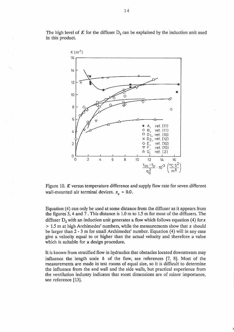
The variable K is a product dependent variable which is also a function of the Archimedes number. A large number of experiments have been made to establish this variable and the results are shown in figure 10.
Figure 10 shows that K may be very different for different products as it varies from 5 to 12 m·1 at high Arhcimedes' numbers.
The figure shows that K increases with increasing Archimedes' number. This is due to the fact that gravity will accelerate the vertical flow close to the opening and generate a stratified air movement in a relatively thin layer along the floor where the obtained velocity level will be retained. This effect is also shown in figure 4. Diffuser A shows an increase in velocity at small Archimedes' number. This increase could be explained by the increase in radial flow which takes place for this diffuser at high Archimedes' number.
14
The high level of K for the diffuser D2 can be explained by the induction unit used in this product.
K (m-1)
16
14
12
10
8
6
4
2
0 0 2 4 6 8 10
• A, ref. [11]
o B, ref. [1 1 J D D 1, ref. [10J x D2 , ref. [12] 0 E, ref. [10J 'V F, ret. E10J .6. G, ref. [ 2J
12 14
0
•
16 Toe -To .
10-3
q2 0
( 0~~2)
Figure 10. K versus temperature difference and supply flow rate for seven different wall-mounted air terminal devices. X
0 = 0.0.
Equation (4) can only be used at some distance from the diffuser as it appears from the figures 3, 4 and 7 . This distance is 1.0 m to 1.5 m for most of the diffusers. The diffuser D2 with an induction unit generates a flow which follows equation ( 4) for x
> 1.5 m at high Archimedes' numbers, while the measurements show that x should be larger than 2- 3 m for small Archimedes' number. Equation (4) will in any case give a velocity equal to or higher than the actual velocity and therefore a value which is suitable for a design procedure.
It is known from stratified flow in hydraulics that obstacles located downstream may influence the length scale o of the flow, see references [7, 8]. Most of the measurements are made in test rooms of equal size, so it is difficult to determine the influence from the end wall and the side walls, but practical experience from the ventilation industry indicates that room dimensions are of minor importance, see reference [13].
15
It is typical that all diffusers, except diffuser F, have reasonable s-izes compared to the test rooms. It might therefore be concluded that the diffusers are tested under conditions and dimensions close to the conditions which they are meant to cover in practice, and the velocity level given by the variable K, in figure 10, is therefore typical of a practical application.
The K -values in figure 10 are from measurements of flow in the middle plane. Measurements by Jacobsen and Nielsen [6] show that K is also a variable of the direction e .
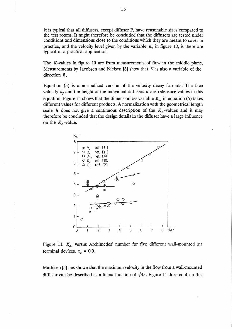
Equation (5) is a normalized version of the velocity decay formula. The face velocity u1 and the height of the individual diffusers h are reference values in this
equation. Figure 11 shows that the dimensionless variable Kdr in equation (5) takes different values for different products. A normalization with the geometrical length scale h does not give a continuous description of the Kdr -values and it may therefore be concluded that the design details in the diffuser have a large influence on the Kdr -value.
Kdr
8~--------------------------------·
7
6
5
4
3
2
• A, ref. [11] o B, ref. [11] o 0 L ref. [101 <> E, ref. [101 t::. G, ref. [2J
<>
0
Figure 11. Kdr versus Archimedes' number for five different wall-mounted au
terminal devices. X0
= 0.0.
Mathisen [5] has shown that the maximum velocity in the flow from a wall-mounted
diffuser can be described as a linear function of .[Xi. Figure 11 does confirm this
16
assumption for large Archimedes' numbers, but deviations take place at smaller Archimedes' numbers.
FLOW BE1WEEN OBSTACLES
The flow in the vicinity of the floor may be influenced by furniture and by other obstacles in the occupied zone. The maximum velocity in the flow is located rather close to the floor (between 1 to 5 cm above the floor), and a great deal of the air movement will therefore take place in this region. Conventional furniture will only have a small influence on the air movement while obstacles placed directly on the floor will block the flow. An opening between this type of obstacles will work as new supply opening because the flow in the room is stratified. Figure 12 shows an example from a room with short movable walls.
Figure 12. Room with short movable walls.
Experiments have shown that the flow from an opening between obstacles can be described as a semi-radial flow like the air movement from a wall-mounted supply opening. The velocity decay can be described by the equation
ux 1 = K -
q ob X 0
(7)
ux is maximum velocity in distance x from the opening and q0
is the excess air
supplied on the other side. ux is measured in the symmetry plane.
Figure 13 shows the measurements of Kob in equation (7). The structure of
equation (7) and the distribution of Kob -values are equivalent to the structure of
17
equation ( 4) and the structure of K -values. The temperature difference T oc - Tob is the difference between the temperature in the height 1.1. m in front of the opening and the lowest temperature in the opening between the obstacles.
Kob(m-1)
16
14-0 0 0
0
12 c9
0<9 oooo
0
10 0
Q<9
81-- ~ go
61--
4t-
2t-
0 0 2 4 6 8
- 10 --Toe- Tob -3(°Cs2) qo2 m6
Figure 13. Kob versus flow rate and temperature difference. Reference [14].
It is interesting to see that the level of the variable Kob is only slightly larger than
the level of K.
The width of the opening is varying from 0.1 m to 1.5 m in the experiment. Measurements show that the importance of the width is less obvious and results for different widths are given in figure 13.
CONCLUSIONS
Wall-mounted air terminal devices are often used in displacement ventilation. The flow from a device will accelerate in a vertical movement close to the opening due to the gravity effect when inlet air is colder than room air. The airflow will then move along the floor in a radial pattern and behave like a stratified flow. The airflow will influence the thermal comfort of the occupants and it is therefore important to develop an expression for the flow for design proposals.
18
Measurements show that the velocity at the floor is not only influenced by the flow rate to the room. It is also influenced by the temperature difference - or by the Archimedes number - and the velocity level may vary for different types of diffusers.
The flow is stratified at large temperature differences. This is indicated by a constant height of the cold flow independent of the distance from the supply opening. It is shown that the radial flow has a virtual origin close to the front of the diffuser. The velocity level in the flow along the floor is inversely proportional to the distance from the diffuser. The velocity decay can be described individually for each type of diffuser by a single equation and a variable which is a function of the Archimedes number. It is further shown that the maximum velocity can be described as a linear function of the square root of the Archimedes number.
The influence of side walls and the end wall has not been studied but it is known from stratified flow in hydraulics that obstacles located downstream may influence the height of the cold flow. Practical experience indicates that the room dimensions are of minor importance, but more work in this area is necessary.
Openings between obstacles placed directly on the floor will generate a flow similar to the air movement in front of a diffuser. It is shown that the velocity distribution can be described with an equation system with the same structure as the system describing the stratified flow from wall-mounted diffusers.
REFERENCES
[1] Nielsen, P.V. "Displacement Ventilation in a Room with Low-Level Diffusers". DKV-Tagungsbericht, ISBN 3-922-429-63-7, Deutscher Kalteund Klimatechnischer Verein e.V., Stuttgart, 1988.
[2] Brohus, H, B0gh, B.-O., Mogensen, F. and Thomsen, T. Private communication, Aalborg University, 1992.
[3] Nielsen, P.V., Hoff, L. and Pedersen, L.G. "Displacement Ventilation by Different Types of Diffusers". Proc. of the 9th AIVC Conference, ISBN 0 946075 40 9, AIVC, Warwick, 1988.
[4] Nielsen, P.V. "Air Velocity at the Floor in a Room with Wall-Mounted Air Terminal Device and Displacement Ventilation" (in Danish). Internal report, Nordic Ventilation Group, ISSN 0902-7513 R9004, Aalborg University, Aalborg, 1990.
[5] Mathisen, H.M. "Analysis and Evaluation of Displacement Ventilation". Ph.D.-thesis, Technical University of Norway, 1989.
19
[6] Jacobsen, T.V. and Nielsen, P.V. 'Velocity and Temperature Distribution in Flow from an Inlet Device in Rooms with Displacement Ventilation". Proc. of Roomvent '92, Third International Conference on Air Distribution in Rooms, DANV AK, Copenhagen, 1992.
[7] Turner, J.S. "Buoyancy Effects in Fluids". Cambridge University Press, Cambridge, 1979.
[8] Nielsen, P.V. 'Velocity Distribution in Rooms with Displacement Ventilation and Low Level Diffusers". Internal report, International Energy Agency, Energy Conservations in Buildings and Community Systems, Annex 20, 1992.
[9] Sandberg, M. and Mattsson M. "The Mechanism of Spread of Negatively Buoyant Air from Low Velocity Air Terminals". IV Seminar on "Application of Fluid Mechanics in Environmental Protection 91", Gliwice, 1991.
PAPER NO. 1: C. E. Hyldgard: Aerodynamic Control of Exhaust. ISSN 0902-7513 R8712.
PAPER NO. 2: Per Heiselberg, Peter V. Nielsen: The Contaminant Distribution in a Ventilated Room with Different Air Terminal Devices. ISSN 0902-7513 R8713.
PAPER NO. 3: Peter V. Nielsen, L. Evensen, Peter Grabau, J . H. Thulesen-Dahl: Air Distribution in Rooms with Ceiling-Mounted Obstacles and Three-Dimensional Flow. ISSN 0902-7513 R8714.
PAPER NO. 4: Peter V. Nielsen, Ake T . A. Moller: Measurements on Buoyant Wall Jet Flows in Air-Conditioned Rooms. ISSN 0902-7513 R8715.
PAPER NO. 5: Peter V. Nielsen: Numerical Prediction of Air Distribution in Rooms. Status and Potentials . ISSN 0902-7513 R8823.
PAPER NO. 6: Peter V. Nielsen, Ake T . Moller: Measurements on Buoyant Jet Flows from a Ceiling-Mounted Slot Diffuser. ISSN 0902-7513 R8832.
PAPER NO. 7: Peter Kofoed, Peter V. Nielsen: Thermal Plumes in Ventilated Rooms - An Experimental Research Work. ISSN 0902-7513 R8833.
PAPER NO. 8: Peter V. Nielsen, Lars Hoff, Lars Germ8Jnn Pedersen: Displacement Ventilation by Different Types of Diffusers. ISSN 0902-7513 R8834.
PAPER NO. 9: Per Heiselberg, Peter V. Nielsen: Flow Conditions in a Mechanically Ventilated Room with a Convective Heat Source. ISSN 0902-7513 R8835.
PAPER NO. 10: Peter V. Nielsen: Displacement Ventilation in a Room with LowLevel Diffusers. ISSN 0902-7513 R8836.
PAPER NO. 11: Peter V. Nielsen: Airflow Simulation Techniques - Progress and Trends. ISSN 0902-7513 R8926.
PAPER NO. 12: M. Skovgaard, C. E. Hyldgaard & P. V. Nielsen: High and Low Reynolds Number Measurements in a Room with an Impinging Isothermal Jet. ISSN 0902-7513 R9003
PAPER NO . 13: M. Skovgaard, P. V. Nielsen: Numerical Prediction of Air Distribution in Rooms with Ventilation of the Mixing Type using the Standard K , £
Model. ISSN 0902-7513 R9042.
PAPER NO. 14: P. Kofoed, P. V. Nielsen: Thermal Plumes in Ventilated Rooms -Measurements in Stratified Surroundings and Analysis by Use of an Extrapolation Method. ISSN 0902-7513 R9043.
PAPER NO. 15: P. Heiselberg, M. Sandberg: Convection from a Slender Cylinder in a Ventilated Room. ISSN 0902-7513 R9044.
PAP ER S ON IN DO OR ENVIRONMENTAL T ECH N OLOGY
PAPER NO. 17: H. Overby, M. Steen-Th~de: Calculation of Vertical Temperature Gradients in Heated Rooms. ISSN 0902-7513 R9046.
PAPER NO. 18: P. V. Nielsen, U. Madsen, D. Tveit: Experiments on an Exhaust Hood for the Paint Industry. ISSN 0902-7513 R9146.
PAPER NO. 19: L. Germann Pedersen, P. V. Nielsen: Exhaust System Reinforced by Jet Flow. ISSN 0902-7513 R9147.
PAPER NO. 20: P. V. Nielsen: Models for the Prediction of Room Air Distribution. ISSN 0902-7513 R9148.
PAPER NO. 21: M. Skovgaard, P. V. Nielsen: Modelling Complex Inlet Geometries in CFD - Applied to Air Flow in Ventilated Rooms. ISSN 0902-7513 R9149.
PAPER NO. 22: M. Skovgaard, P. V. Nielsen: Numerical Investigation of Transitional Flow over a Backward Facing Step using a Low Reynolds Number k - c Model. ISSN 0902-7513 R9150.
PAPER NO. 23: P. Kofoed, P. V. Nielsen: A uftriebsstromungen verschiedener Warmequellen - Einfiuss der umgebenden Wande auf den geforderten Volumenstrom. ISSN 0902-7513 R9151.
PAPER NO. 24: P. Heiselberg: Concentration Distribution in a Ventilated Room . under Isothermal Conditions. ISSN 0902-7513 R9152.
PAPER NO. 25: P. V. Nielsen: Air Distribution Systems - Room Air Movement and Ventilation Effectiveness. ISSN 0902-7513 R9250.
PAPER NO. 26: P. V. Nielsen: Description of Supply Openings in Numerical Models for Room Air Distribution ISSN 0902-7513 R9251.
PAPER NO. 27: P. V. Nielsen: Velocity Distribution in the Flow from a Wallmounted Diffuser in Rooms with Displacement Ventilation. ISSN 0902-7513 R9252.
PAPER NO. 28: T. V. Jacobsen & P. V. Nielsen: Velocity and Temperature Distribution in Flow from an Inlet Device in Rooms with Displacement Ventilation. ISSN 0902-7513 R9253.
PAPER NO. 29: P. Heiselberg: Dispersion of Contaminants in Indoor Climate. ISSN 0902-7513 R9254.
PAPER NO. 30: P. Heiselberg & N. C. Bergs~e: Measurements of Contaminant Dispersion in Ventilated Rooms by a Passive Tracer Gas Technique. ISSN 0902-7513 R9255.
PAPER NO. 31: K. S. Christensen: Numerical Prediction of Airflow in a Room with Ceiling-Mounted Obstacles. ISSN 0902-7513 R9256.
Department of Building Technology and Structural Engineering The University of Aalborg, Sohngaardsholmsvej 57. DK 9000 Aalborg Telephone: 45 98 15 85 22 Telefax: 45 98 14 82 43