/ Battery Charging Systems / Welding Technology / Solar Electronics DE EN FR Instructions d’installation Einbauanleitung Installation Instruction Ethernet inside AB Ethernet IP inside Extension de système System add-on Systemerweiterung 42,0410,1383 002-11042012
Transcript
/ Battery Charging Systems / Welding Technology / Solar Electronics
Rückfront in Stromquelle einbauen ............................................................................................................... 8Rückfront in Stromquelle einbauen .......................................................................................................... 8
Fronius Worldwide
2
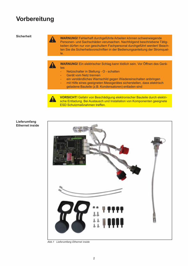
WARNUNG! Fehlerhaft durchgeführte Arbeiten können schwerwiegendePersonen- und Sachschäden verursachen. Nachfolgend beschriebene Tätig-keiten dürfen nur von geschultem Fachpersonal durchgeführt werden! Beach-ten Sie die Sicherheitsvorschriften in der Bedienungsanleitung der Stromquel-le.
Vorbereitung
WARNUNG! Ein elektrischer Schlag kann tödlich sein. Vor Öffnen des Gerä-tes- Netzschalter in Stellung - O - schalten- Gerät vom Netz trennen- ein verständliches Warnschild gegen Wiedereinschalten anbringen- mit Hilfe eines geeigneten Messgerätes sicherstellen, dass elektrisch
geladene Bauteile (z.B. Kondensatoren) entladen sind
VORSICHT! Gefahr von Beschädigung elektronischer Bauteile durch elektri-sche Entladung. Bei Austausch und Installation von Komponenten geeigneteESD Schutzmaßnahmen treffen.
Sicherheit
LieferumfangEthernet inside
Abb.1 Lieferumfang Ethernet inside
3
DE
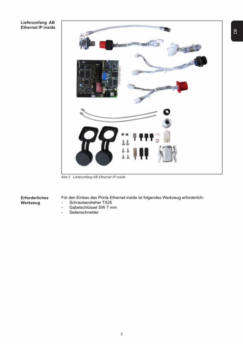
Lieferumfang ABEthernet IP inside
Abb.2 Lieferumfang AB Ethernet IP inside
Für den Einbau des Prints Ethernet inside ist folgendes Werkzeug erforderlich:- Schraubendreher TX25- Gabelschlüssel SW 7 mm- Seitenschneider
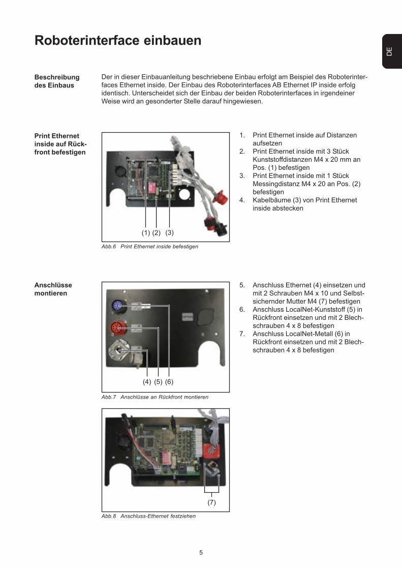
2. Print Ethernet inside mit 3 StückKunststoffdistanzen M4 x 20 mm anPos. (1) befestigen
3. Print Ethernet inside mit 1 StückMessingdistanz M4 x 20 an Pos. (2)befestigen
4. Kabelbäume (3) von Print Ethernetinside abstecken
Abb.6 Print Ethernet inside befestigen
Abb.7 Anschlüsse an Rückfront montieren
(4) (5) (6)
5. Anschluss Ethernet (4) einsetzen undmit 2 Schrauben M4 x 10 und Selbst-sichernder Mutter M4 (7) befestigen
6. Anschluss LocalNet-Kunststoff (5) inRückfront einsetzen und mit 2 Blech-schrauben 4 x 8 befestigen
7. Anschluss LocalNet-Metall (6) inRückfront einsetzen und mit 2 Blech-schrauben 4 x 8 befestigen
(3)
(7)
Abb.8 Anschluss-Ethernet festziehen
Anschlüssemontieren
Der in dieser Einbauanleitung beschriebene Einbau erfolgt am Beispiel des Roboterinter-faces Ethernet inside. Der Einbau des Roboterinterfaces AB Ethernet IP inside erfolgidentisch. Unterscheidet sich der Einbau der beiden Roboterinterfaces in irgendeinerWeise wird an gesonderter Stelle darauf hingewiesen.
Beschreibungdes Einbaus
6
Anschlüsseeinstecken
(8)
7. Kabelbaum für VerbindungsanschlussLocalNet an Pos (8) in Print Ethernetinside einstecken
(9)
8. Anschluss LocalNet-Metall in PrintEthernet inside in Pos. (9) einstecken
(10)
Abb.9 Verbindungsanschluss LocalNet einstecken
Abb.10 LocalNet-Metall einstecken
Abb.11 LocalNet-Kunststoff einstecken
9. Anschluss LocalNet-Kunststoff inPrint Ethernet inside in Pos. (10)einstecken
7
DE
Anschlüsseeinstecken(Fortsetzung)
(11) (12) (13)
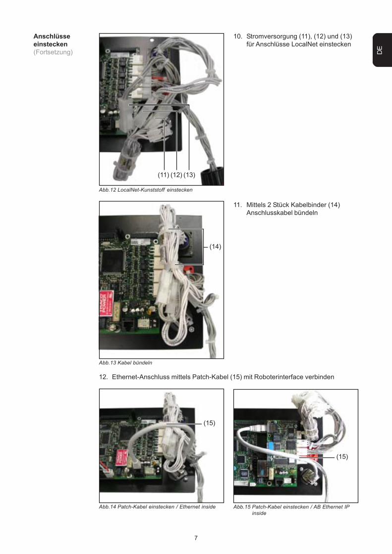
10. Stromversorgung (11), (12) und (13)für Anschlüsse LocalNet einstecken
12. Ethernet-Anschluss mittels Patch-Kabel (15) mit Roboterinterface verbinden
Abb.15 Patch-Kabel einstecken / AB Ethernet IPinside
(15)
8
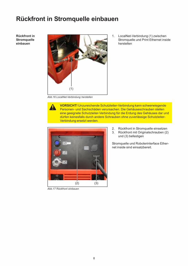
Rückfront in Stromquelle einbauen
Rückfront inStromquelleeinbauen
(1)
1. LocalNet-Verbindung (1) zwischenStromquelle und Print Ethernet insideherstellen
Abb.16 LocalNet-Verbindung herstellen
Abb.17 Rückfront einbauen
(2) (3)
2. Rückfront in Stromquelle einsetzen3. Rückfront mit Originalschrauben (2)
und (3) befestigen
Stromquelle und Roboterinterface Ether-net inside sind einsatzbereit.
VORSICHT! Unzureichende Schutzleiter-Verbindung kann schwerwiegendePersonen- und Sachschäden verursachen. Die Gehäuseschrauben stelleneine geeignete Schutzleiter-Verbindung für die Erdung des Gehäuses dar unddürfen keinesfalls durch andere Schrauben ohne zuverlässige Schutzleiter-Verbindung ersetzt werden.
1
EN
Table of contentsPreparations .................................................................................................................................................. 2
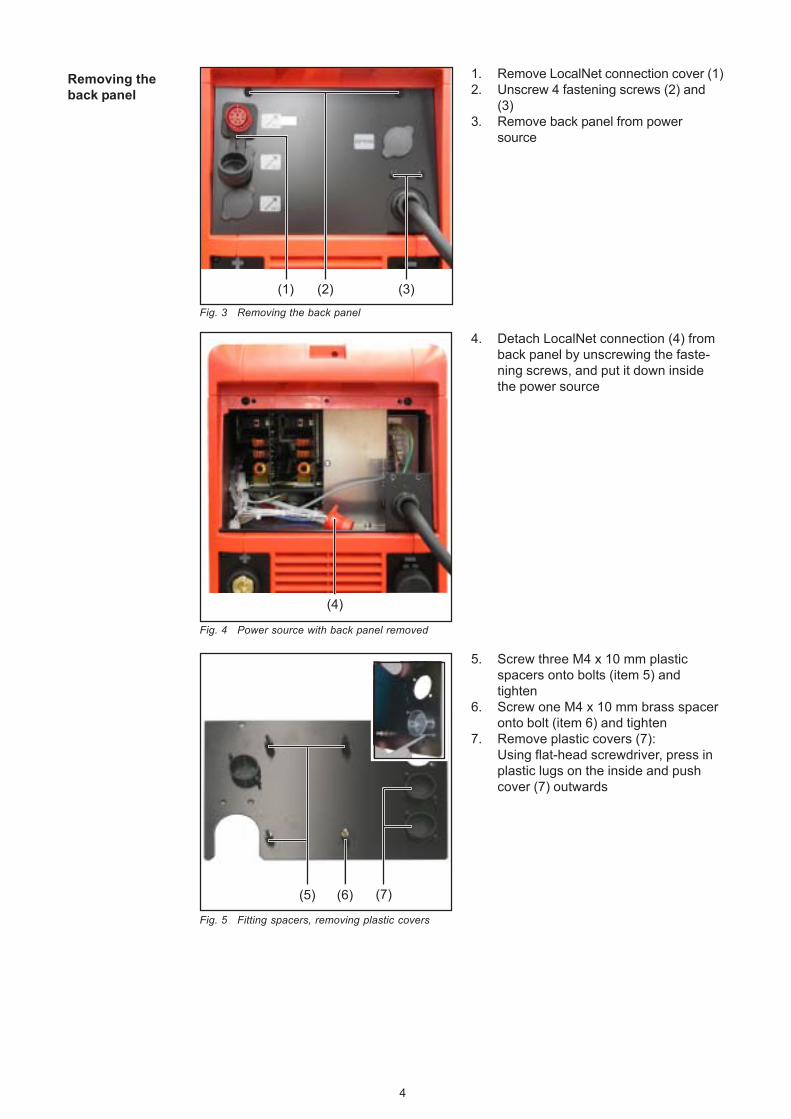
Safety ....................................................................................................................................................... 2Scope of supply ........................................................................................................................................ 2Scope of supply AB Ethernet IP inside ..................................................................................................... 3Tools required .......................................................................................................................................... 3Removing the back panel ......................................................................................................................... 4
Installing the robot interface .......................................................................................................................... 5How to install the interface ....................................................................................................................... 5Fastening Ethernet inside board to back panel ........................................................................................ 5Installing connections ............................................................................................................................... 5Plugging in connections ........................................................................................................................... 6
Inserting the back panel in the power source ................................................................................................ 8Inserting the back panel in the power source ........................................................................................... 8
Fronius Worldwide
2
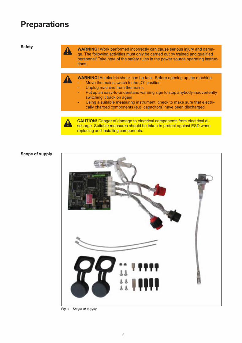
WARNING! Work performed incorrectly can cause serious injury and dama-ge. The following activities must only be carried out by trained and qualifiedpersonnel! Take note of the safety rules in the power source operating instruc-tions.
Preparations
WARNING! An electric shock can be fatal. Before opening up the machine- Move the mains switch to the „O“ position- Unplug machine from the mains- Put up an easy-to-understand warning sign to stop anybody inadvertently
switching it back on again- Using a suitable measuring instrument, check to make sure that electri-
cally charged components (e.g. capacitors) have been discharged
CAUTION! Danger of damage to electrical components from electrical di-scharge. Suitable measures should be taken to protect against ESD whenreplacing and installing components.
Safety
Scope of supply
Fig. 1 Scope of supply
3
EN
Scope of supplyAB Ethernet IPinside
Fig. 2 Scope of supply AB Ethernet IP inside
The following tools are required to fit the Ethernet inside board:- Screwdriver TX25- Flat spanner size 7 mm- Diagonal cutting pliers
5. Insert Ethernet connection (4) andfasten using two M4 x 10 screws andself-locking nuts M4 (7)
6. Insert plastic LocalNet connection (5)into back panel and fasten using two4 x 8 self-tapping screws
7. Insert metal LocalNet connection (6)into back panel and fasten using two4 x 8 self-tapping screws
(3)
(7)
Fig. 8 Tightening the Ethernet connection
Installing con-nections
How to install theinterface
The installation procedure described in this document is based on the Ethernet insiderobot interface. The AB Ethernet IP inside robot interface is installed in exactly the sameway. Should the installation procedure be at all different, this will be highlighted accordingly.
6
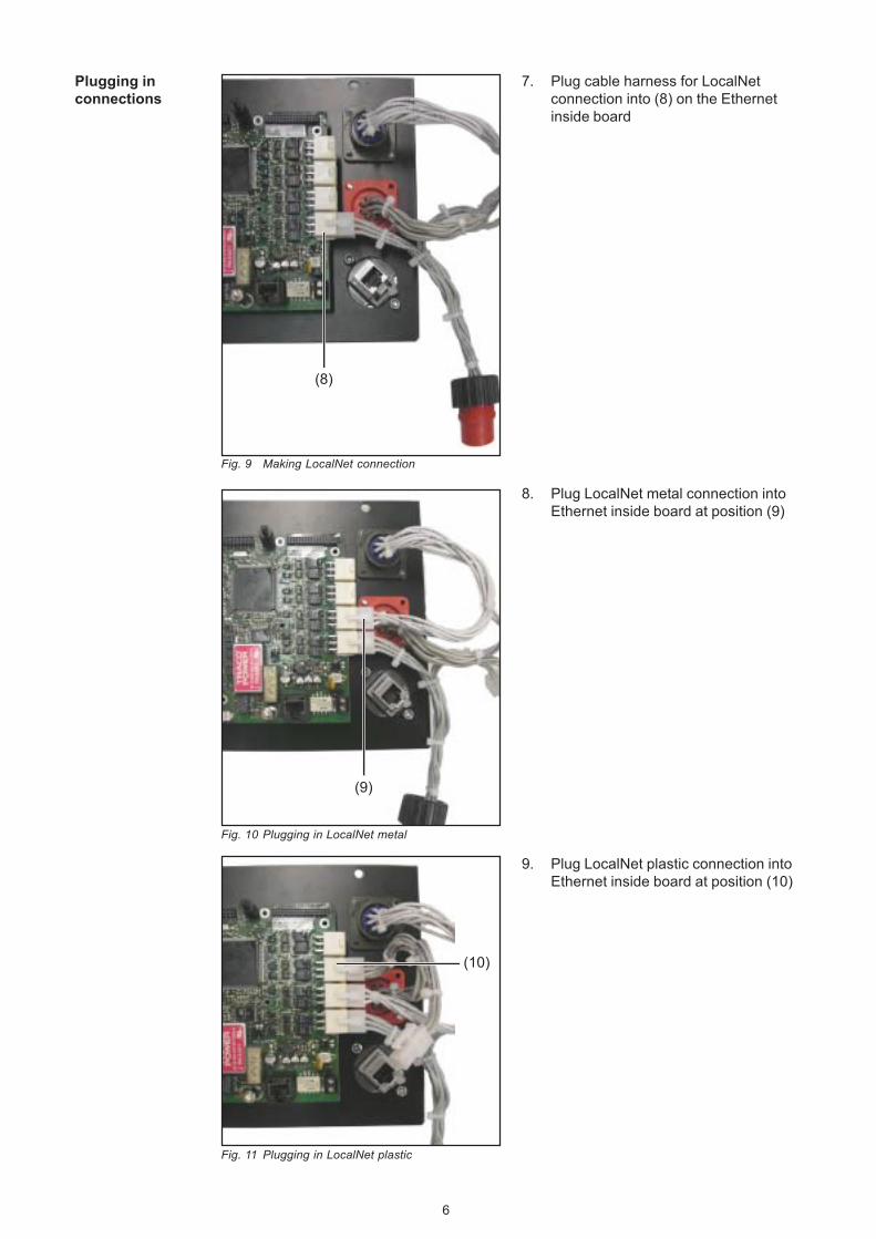
Plugging inconnections
(8)
7. Plug cable harness for LocalNetconnection into (8) on the Ethernetinside board
(9)
8. Plug LocalNet metal connection intoEthernet inside board at position (9)
(10)
Fig. 9 Making LocalNet connection
Fig. 10 Plugging in LocalNet metal
Fig. 11 Plugging in LocalNet plastic
9. Plug LocalNet plastic connection intoEthernet inside board at position (10)
7
EN
Plugging inconnections(continued)
(11) (12) (13)
10. Connect power supply (11), (12) and(13) for LocalNet connections
Fig. 12 Plugging in LocalNet plastic
Fig. 13 Bundling cables
11. Using 2 cable ties (14), bundle con-necting cables together
(14)
Fig. 14 Plugging in the patch cable/Ethernet inside
(15)
12. Make the Ethernet connection by plugging the patch cable (15) into the robot inter-face
Fig. 15 Plugging in the patch cable/AB Ethernet IPinside
(15)
8
Inserting the back panel in the power source
Inserting theback panel in thepower source
(1)
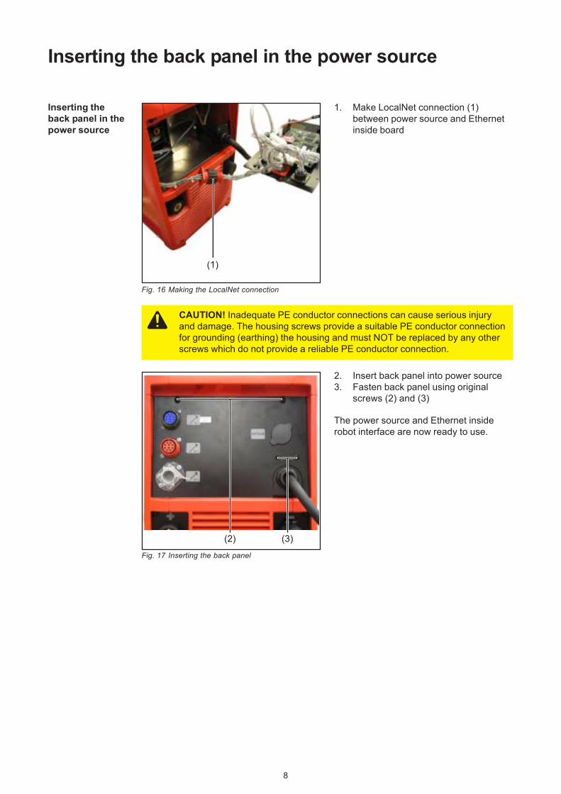
1. Make LocalNet connection (1)between power source and Ethernetinside board
Fig. 16 Making the LocalNet connection
Fig. 17 Inserting the back panel
(2) (3)
2. Insert back panel into power source3. Fasten back panel using original
screws (2) and (3)
The power source and Ethernet insiderobot interface are now ready to use.
CAUTION! Inadequate PE conductor connections can cause serious injuryand damage. The housing screws provide a suitable PE conductor connectionfor grounding (earthing) the housing and must NOT be replaced by any otherscrews which do not provide a reliable PE conductor connection.
Sécurité .................................................................................................................................................... 2Livraison ................................................................................................................................................... 2Livraison AB Ethernet IP inside ................................................................................................................ 3Outils requis ............................................................................................................................................. 3Démonter le panneau arrière ................................................................................................................... 4
Installer l’interface robot ................................................................................................................................ 5Description de l’installation ....................................................................................................................... 5Fixer le circuit imprimé Ethernet interne sur le panneau arrière ............................................................... 5Monter les connecteurs ............................................................................................................................ 5Brancher les connecteurs ........................................................................................................................ 6
Monter le panneau arrière dans la source de courant ................................................................................... 8Monter le panneau arrière dans la source de courant .............................................................................. 8
Fronius Worldwide
2
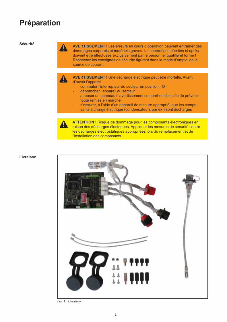
AVERTISSEMENT ! Les erreurs en cours d’opération peuvent entraîner desdommages corporels et matériels graves. Les opérations décrites ci-aprèsdoivent être effectuées exclusivement par le personnel qualifié et formé !Respectez les consignes de sécurité figurant dans le mode d’emploi de lasource de courant.
Préparation
AVERTISSEMENT ! Une décharge électrique peut être mortelle. Avantd’ouvrir l’appareil- commuter l’interrupteur du secteur en position - O -- débrancher l’appareil du secteur- apposer un panneau d’avertissement compréhensible afin de prévenir
toute remise en marche- s’assurer, à l’aide d’un appareil de mesure approprié, que les compo-
sants à charge électrique (condensateurs par ex.) sont déchargés
ATTENTION ! Risque de dommage pour les composants électroniques enraison des décharges électriques. Appliquer les mesures de sécurité contreles décharges électrostatiques appropriées lors du remplacement et del’installation des composants.
Sécurité
Livraison
Fig. 1 Livraison
3
FR
Livraison ABEthernet IP inside
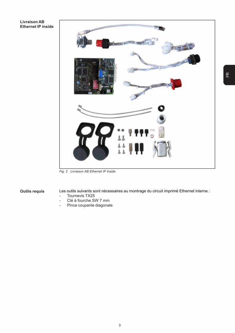
Fig. 2 Livraison AB Ethernet IP inside
Les outils suivants sont nécessaires au montrage du circuit imprimé Ethernet interne :- Tournevis TX25- Clé à fourche SW 7 mm- Pince coupante diagonale
Outils requis
4
Démonter lepanneau arrière
(1) (2) (3)
1. Enlever le cache du connecteurLocalNet (1)
2. Desserrer les 4 vis de fixation (2) et(3)
3. Sortir le panneau arrière de la sourcede courant
Fig. 3 Démonter le panneau arrière
(5) (6) (7)
(4)
Fig. 4 Source de courant sans panneau arrière
4. Dégager le connecteur LocalNet (4)en sortant les vis de fixation dupanneau arrière et le déposer dans lasource de courant
5. Visser et serrer fermement les 3écarteurs en plastique M4 x 10 mmsur les vis Pos. (5)
6. Visser et serrer fermement l’écarteuren laiton M4 x 10 mm sur les vis Pos.(6)
7. Enlever le cache en plastique (7) :A l’aide d’un tournevis plat, enfoncerles deux taquets en plastique sur laface intérieure et pousser le cachevers l’extérieur
Fig. 5 Monter les écarteurs, retirer les caches enplastique
5
FR
Installer l’interface robot
Fixer le circuitimprimé Ethernetinterne sur lepanneau arrière
(1) (2)
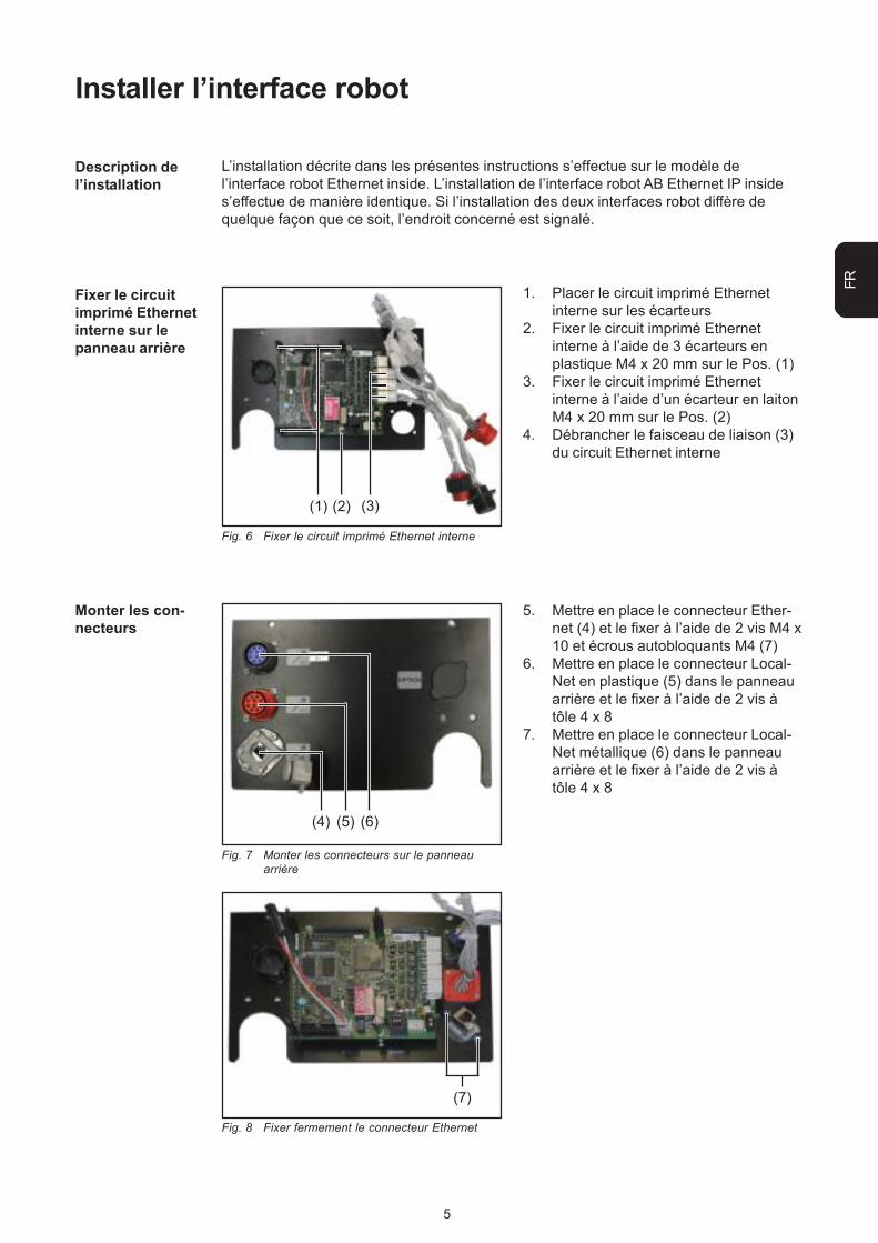
1. Placer le circuit imprimé Ethernetinterne sur les écarteurs
2. Fixer le circuit imprimé Ethernetinterne à l’aide de 3 écarteurs enplastique M4 x 20 mm sur le Pos. (1)
3. Fixer le circuit imprimé Ethernetinterne à l’aide d’un écarteur en laitonM4 x 20 mm sur le Pos. (2)
4. Débrancher le faisceau de liaison (3)du circuit Ethernet interne
Fig. 6 Fixer le circuit imprimé Ethernet interne
Fig. 7 Monter les connecteurs sur le panneauarrière
(4) (5) (6)
5. Mettre en place le connecteur Ether-net (4) et le fixer à l’aide de 2 vis M4 x10 et écrous autobloquants M4 (7)
6. Mettre en place le connecteur Local-Net en plastique (5) dans le panneauarrière et le fixer à l’aide de 2 vis àtôle 4 x 8
7. Mettre en place le connecteur Local-Net métallique (6) dans le panneauarrière et le fixer à l’aide de 2 vis àtôle 4 x 8
(3)
(7)
Fig. 8 Fixer fermement le connecteur Ethernet
Monter les con-necteurs
Description del’installation
L’installation décrite dans les présentes instructions s’effectue sur le modèle del’interface robot Ethernet inside. L’installation de l’interface robot AB Ethernet IP insides’effectue de manière identique. Si l’installation des deux interfaces robot diffère dequelque façon que ce soit, l’endroit concerné est signalé.
6
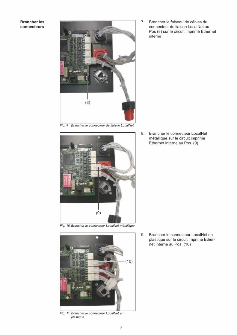
Brancher lesconnecteurs
(8)
7. Brancher le faiseau de câbles duconnecteur de liaison LocalNet auPos (8) sur le circuit imprimé Ethernetinterne
(9)
8. Brancher le connecteur LocalNetmétallique sur le circuit impriméEthernet interne au Pos. (9)
(10)
Fig. 9 Brancher le connecteur de liaison LocalNet
Fig. 10 Brancher le connecteur LocalNet métallique
Fig. 11 Brancher le connecteur LocalNet enplastique
9. Brancher le connecteur LocalNet enplastique sur le circuit imprimé Ether-net interne au Pos. (10)
7
FR
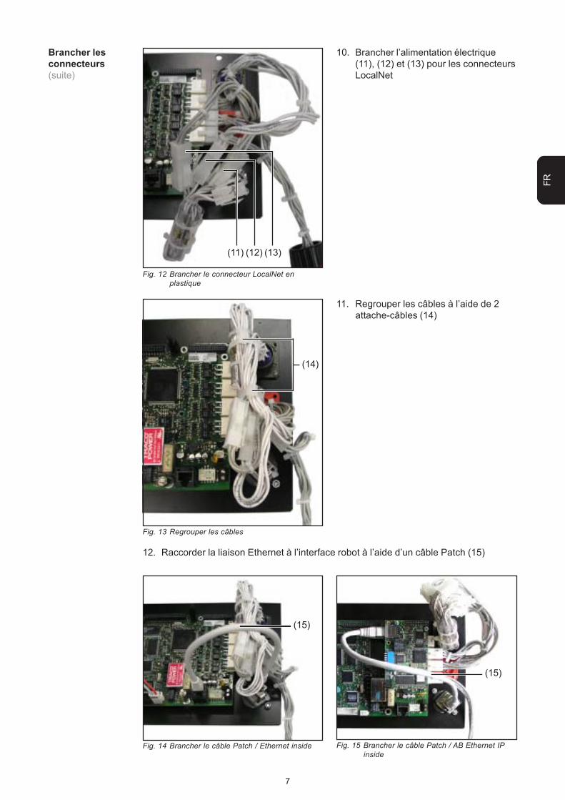
Brancher lesconnecteurs(suite)
(11) (12) (13)
10. Brancher l’alimentation électrique(11), (12) et (13) pour les connecteursLocalNet
Fig. 12 Brancher le connecteur LocalNet enplastique
Fig. 13 Regrouper les câbles
11. Regrouper les câbles à l’aide de 2attache-câbles (14)
(14)
Fig. 14 Brancher le câble Patch / Ethernet inside
(15)
Fig. 15 Brancher le câble Patch / AB Ethernet IPinside
(15)
12. Raccorder la liaison Ethernet à l’interface robot à l’aide d’un câble Patch (15)
8
Monter le panneau arrière dans la source de courant
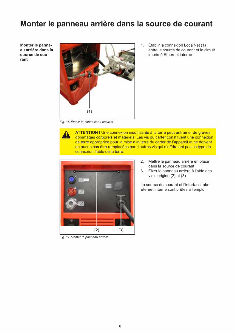
Monter le panne-au arrière dans lasource de cou-rant
(1)
1. Établir la connexion LocalNet (1)entre la source de courant et le circuitimprimé Ethernet interne
Fig. 16 Établir la connexion LocalNet
Fig. 17 Monter le panneau arrière
(2) (3)
2. Mettre le panneau arrière en placedans la source de courant
3. Fixer le panneau arrière à l’aide desvis d’origine (2) et (3)
La source de courant et l’interface tobotEternet interne sont prêtes à l’emploi.
ATTENTION ! Une connexion insuffisante à la terre peut entraîner de gravesdommages corporels et matériels. Les vis du carter constituent une connexionde terre appropriée pour la mise à la terre du carter de l’appareil et ne doiventen aucun cas être remplacées par d’autres vis qui n’offriraient pas ce type deconnexion fiable de la terre.
ud_fr_st_so_00082 012011
FRONIUS INTERNATIONAL GMBHFroniusplatz 1, A-4600 Wels, Austria