35
Enhanced availability of transformers via transformer remote monitoring - TEC ABB Power Products Service Raben Naidoo, Technology days, May 21-22th, 2014, Cape Town, South Africa,

Enhanced availability of transformers via transformer remote monitoring - TEC ABB Power Products Service
Raben Naidoo, Technology days, May 21-22th, 2014, Cape Town, South Africa,

Source: Black & Veatch’s 2011 Strategic Directions Survey Results
Why a session on availability? Top utility concerns
© ABB BU Transformers May 27, 2014 | Slide 2
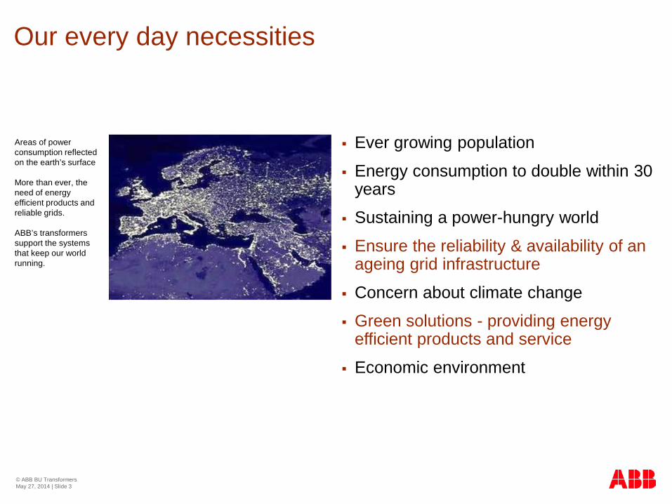
Our every day necessities
Ever growing population
Energy consumption to double within 30 years
Sustaining a power-hungry world
Ensure the reliability & availability of an ageing grid infrastructure
Concern about climate change
Green solutions - providing energy efficient products and service
Economic environment
© ABB BU Transformers May 27, 2014 | Slide 3
Areas of power consumption reflected on the earth’s surface
More than ever, the need of energy efficient products and reliable grids. ABB’s transformers support the systems that keep our world running.

Utility and Industry challenges Asset management with new challenges
Ensure high reliability of aged assets
Avoid unplanned power outage
Optimize assets performance
Increase production output
© ABB BU Transformers May 27, 2014 | Slide 4
Move towards Condition Based Maintenance / Reliability Centered
Need for tools to decide based on technical & economical criteria
Optimize capital expenditure and increase return on assets
Reduce Life Cycle Costs – Lowest operation and maintenance costs
Extend lifetime of existing assets while looking for sustainability
Delay investments while considering green solutions
Failure probabilities (Network Transfor.)
0
0.02
0.04
0.06
0.08
0.1
1 6 11 16 21 26 31 36 41 46 51 56Age (years)
Pro
bab
ilit
y

How to enhance availability?
Avoid unexpected failures
Plan maintenance and repair during low load periods
Efficient maintenance actions reducing downtime
Solutions to shorter repair time
Retrofit solution to increase personal and asset safety
Green footprint
Financial benefits
© ABB BU Transformers May 27, 2014 | Slide 5

Condition based maintenance Assess the condition / withstand capability
© ABB BU Transformers May 27, 2014 | Slide 6
Thermal ageing Temperature Moisture Oxygen
Mechanical ageing Delta temperature Over current Vibration / Number of operation
Electrical ageing Over voltage Over current Harmonics - VFT
Source: CIGRE
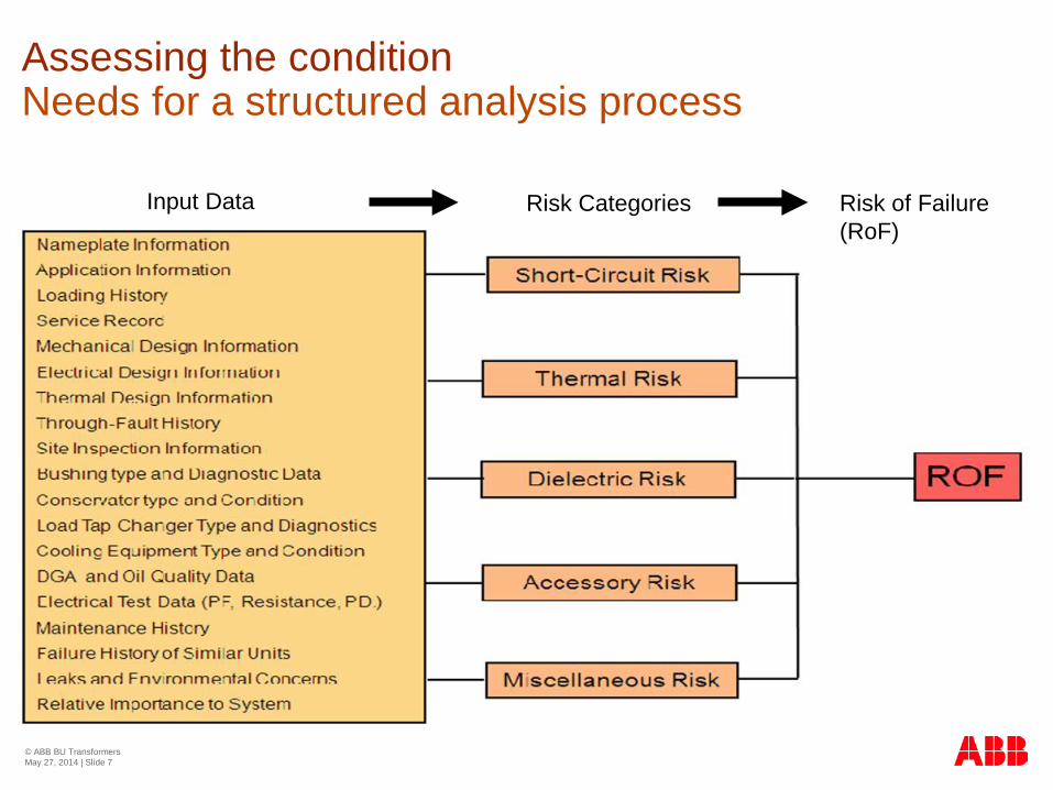
Assessing the condition Needs for a structured analysis process
Input Data Risk Categories
© ABB BU Transformers May 27, 2014 | Slide 7
Risk of Failure (RoF)
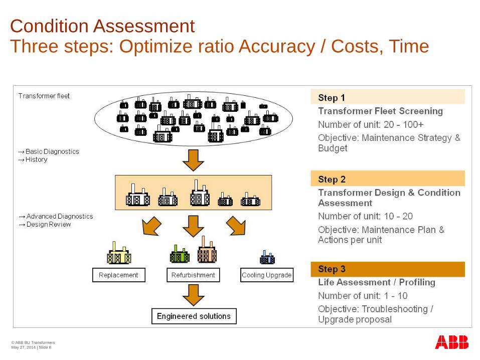
Condition Assessment Three steps: Optimize ratio Accuracy / Costs, Time
© ABB BU Transformers May 27, 2014 | Slide 8

Electrical tests and DGA Diagnostic matrix
Overall condition
Oil, DGA, Furans
Mechanical condition
Frequency Response Analysis (FRA)
Thermal condition
Dielectric Frequency Response (DFR)
Electrical condition
Partial Discharge Analysis (PDA)
Accessories
Bushing Power Factor
OTC Vibration
© ABB BU Transformers May 27, 2014 | Slide 9

Mechanical Electrical Thermal Accessories Overall Risk Mitigation - Actions
TFO 2 Winding Arcing Heating 95 Visual Inspection and repair in factory / rewinding
TFO 5 Tank OLTC heating 80 Repair on site and OLTC overhaul
TFO 1 Aged oil Bushing 70 Oil regeneration / filtration and advanced diagnosis / change HV bushing
TFO 6 Arcing Thermometer 50 Exchange TopOil - thermometer / on line monitoring of DGA
TFO 3 Silicagel 40 Exchange Silicagel
TFO 7 25 Standard maintenance actions and controls
TFO 8 15 Standard maintenance actions and controls / 10 % overload capabilities
TFO 4 10 Standard maintenance actions and controls / 15 % overload capabilities
Plant 1 - Results of condition assessement and action plan
Transformer condition assessment Typical output and recommendations
© ABB BU Transformers May 27, 2014 | Slide 10

Utility, ZA – Belhar and Dinaledi Substation
Pilot Installation Utility, South Africa, Western Cape & North West Year: 2012
Customers need Lower shutdown periods
Reduce OLTC maintenance scheduling
Trouble-free operation
ABB’s response Vacuum On-load tap changer
Immediate prognosis allowing to take appropriate actions before a problem occurs
Customers benefits Lower life cycle costs, less maintenance needs, and increased
time in operation because of a radical reduction in contact wear.
Routine inspection takes place in a cleaner environment which reduces downtime.
Only the diverter switch mechanism differs which means that the unit is completely interchangeable, thus no redesign of the transformer is necessary.
Operation of the transformers has become more efficient allowing overloading and aging forecasting on-line. Online Monitoring has increased the availability of the transformers
Transformer Service Success Story
© ABB BU Transformers May 27, 2014 | Slide 11

Monitoring Infrastructure from sensor to repair or upgrade
© ABB BU Transformers May 27, 2014 | Slide 12
Upgrades
Optimum Grid Control and
Dynamic Overload Control Integration - Load Forecast -
Temperature algorithms
Transformers Substations
Consulting
Asset Health Management
Data Aggregation Monitoring – data storage, local service and
control – remote control
Sensor Technologies Basic and advanced sensors. Local display and preparation for
remote connection
Grid integration – Asset Health Center Fleet Screening / Assessment
Service Transformers
Enable smart transformer management
Monitoring enables smart grids for:
Fleet assessment Optimum control
TEC

Voltage, Current,
Gases and Bushing, etc,
On load Tap Changer, Oil and Ambient Temperature,
Communication system
Online Transformer Monitoring
“ABB” monitoring system (converts raw data into useful informations)
© ABB BU Transformers May 27, 2014 | Slide 13

Online Transformer Monitoring
Control Room
© ABB BU Transformers May 27, 2014 | Slide 14

TEC platform – key benefits
User friendly web interface – no additional software needed on users computer
Based on a microprocessor and Modular design, possible to add the sensors that the customer requests with additional hardware
Very strong mechanical stability and temperature endurance => Long lifespan
Reliable and proven technology (longest serving unit has >10 years in the field)
Compact and easy to install
Support for standard communication protocols, including IEC 61850 (certified by SGCC)
© ABB BU Transformers May 27, 2014 | Slide 15

No special computer is
needed
Dual language support
User friendly interface
© ABB BU Transformers May 27, 2014 | Slide 16
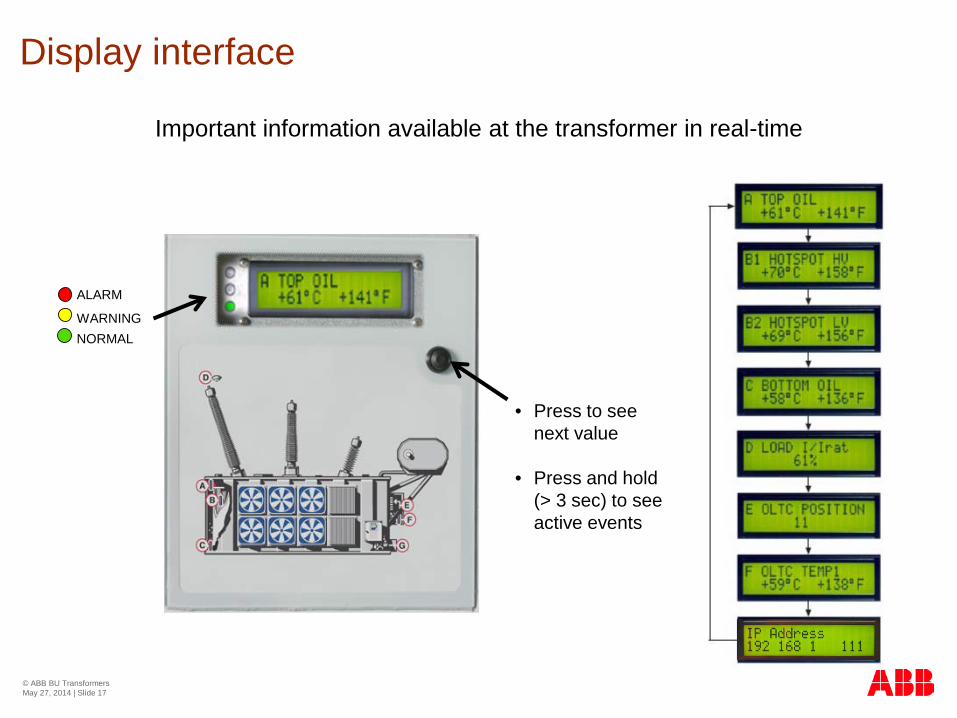
Display interface
Important information available at the transformer in real-time
• Press to see next value
• Press and hold (> 3 sec) to see active events
ALARM
WARNING NORMAL
© ABB BU Transformers May 27, 2014 | Slide 17
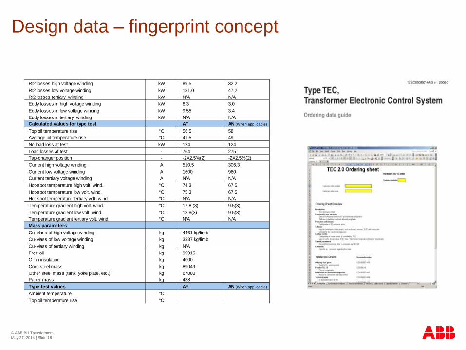
RI2 losses high voltage winding kW 89.5 32.2RI2 losses low voltage winding kW 131.0 47.2RI2 losses tertiary winding kW N/A N/AEddy losses in high voltage winding kW 8.3 3.0Eddy losses in low voltage winding kW 9.55 3.4Eddy losses in tertiary winding kW N/A N/ACalculated values for type test AF AN (When applicable)
Top oil temperature rise °C 56.5 58Average oil temperature rise °C 41.5 49No load loss at test kW 124 124Load losses at test - 764 275Tap-changer position - -2X2.5%(2) -2X2.5%(2)Current high voltage winding A 510.5 306.3Current low voltage winding A 1600 960Current tertiary voltage winding A N/A N/AHot-spot temperature high volt. wind. °C 74.3 67.5Hot-spot temperature low volt. wind. °C 75.3 67.5Hot-spot temperature tertiary volt. wind. °C N/A N/ATemperature gradient high volt. wind. °C 17.8 (3) 9.5(3)Temperature gradient low volt. wind. °C 18.8(3) 9.5(3)Temperature gradient tertiary volt. wind. °C N/A N/AMass parametersCu-Mass of high voltage winding kgCu-Mass of low voltage winding kgCu-Mass of tertiary winding kgFree oil kgOil in insulation kgCore steel mass kgOther steel mass (tank, yoke plate, etc.) kgPaper mass kgType test values AF AN (When applicable)
Ambient temperature °CTop oil temperature rise °C
438
3337 kg/limbN/A999154000
67000
4461 kg/limb
89049
Design data – fingerprint concept
© ABB BU Transformers May 27, 2014 | Slide 18

Web interface – graphs with data
© ABB BU Transformers May 27, 2014 | Slide 19

Intelligent cooling control
Signal from
CT
TEC Cabinet
T Top Oil
T Bottom Oil Thermometer pocket
Hot-spot temp
ON CABINET
ALARM
WARNING
NORMAL
Display
Algorithms
Group 1 Group 3
Up to 6 Cooler Groups can be controlled
Group 2 Group 4
Group 5
Group 6
Enhancements from traditional cooling
• Control up to 6 cooler groups
• Starts on top oil, hot-spot and forecast
• Remote start of coolers possible
• All cooler groups equally used
• Logic to exercise motors each week
• Time in service shown in station interface
• Time delay between cooler group start
• Reduced noise level
• More stable temperature, reduced breathing
Traditional top oil thermometer used as back-up start of coolers and for emergency trip
© ABB BU Transformers May 27, 2014 | Slide 20

Wear on: • Right side of Fixed Contact 4 • Main Contact W = C . In
7
6
5
4
3
2
1
I
7
6
5
4
3
2
1
I
IcIc
Wear on: • Right side on Fixed Contact 4 • Left Transition Contact W = C. (I/2-Ic)n
Contact wear calculation according to theory and experience
On load tap changer
Position statistics
Temperature
Contact Wear
© ABB BU Transformers May 27, 2014 | Slide 21

No traditional hot-spot thermometer needed
Hot-spot temperature calculation • HV winding
• LV winding • Tertiary winding
Hot-spot Temperature Calculation – IEC & IEEE
yroh KHg+Θ=Θ
IEC-354 Θo = Top oil temperature Hgr = Hot-spot to top-oil gradient K = Load factor (load current/rated current) y = Winding exponent
© ABB BU Transformers May 27, 2014 | Slide 22

Thermal Ageing at the Hot-Spot Ageing calculation gives a possibility to compare the thermal ageing of different transformers, for overload or replacement planning
0.001 ~0%
0.01 1%
0.1 10%
1 100%
10 1000%
50 100
Hot-Spot Temperature [ °C]
Aging Speed
IEC, used for normal paper
IEEE, used for thermally upgraded paper
−
= 6 98 T
IEC
HS
2 F ( )
+
− = 273 T
15000 383
15000
IEEE HS e F
Calculated age of the transformer
Aging Speed at this time
© ABB BU Transformers May 27, 2014 | Slide 23

Overload Capability
Overload capacity: Displays the loading capability at present conditions
© ABB BU Transformers May 27, 2014 | Slide 24

Cooling from Radiators or Coolers
Losses
T Top Oil
T Bottom Oil
T Air
Cooling from the Tank
TEC keeps track of the transformer temperatures and compares them with a theoretical model to indicate changes, in the cooling conditions or heat generation, that could place restrictions on the overloading capacity.
Transformer Temperature Balance
© ABB BU Transformers May 27, 2014 | Slide 25

Gas and moisture measurement
To be able to analyze gas readings it have to be correlated with load, temperatures and cooling status in the transformer
TEC keeps track of the transformer and helps you analyze gas readings together with all relevant transformer data.
To know when an oil sample is needed.
Combination of load, temperatures, cooling status and DGA is required to give the complete picture
Early warnings for fast developing gas related faults
© ABB BU Transformers May 27, 2014 | Slide 26

TEC few sensors high functionality
On-load tap-changer (OLTC) Position Contact wear Temperature Temperature balance Moisture OLTC
Gases and moisture Trends Bubbling temperature
Current transducers Hot-spot temperature Load Ageing Cooling control Contact wear Temperature balance
Bottom oil temperature Temperature balance
Ambient temperature Sun Shadow
Top oil temperature Hot-spot temperature Load Ageing Temperature balance Cooling control
Cabling One cable to/from transformer Bus communication available
on transformer
© ABB BU Transformers May 27, 2014 | Slide 27

TEC system
TCP/IP
Fiber optic
Gas sensor
Connection with customer´s network
Minimum scope of supply
© ABB BU Transformers May 27, 2014 | Slide 28

TMU 100 Bushing monitoring Capacitance Tan delta
DGA device Individual 8 gases Moisture TEC system
Thermal Currents Coolers OLTC
TCP/IP
Fiber optic
Connection with customer´s network
© ABB BU Transformers May 27, 2014 | Slide 29

Connection with customer´s network
© ABB BU Transformers May 27, 2014 | Slide 30
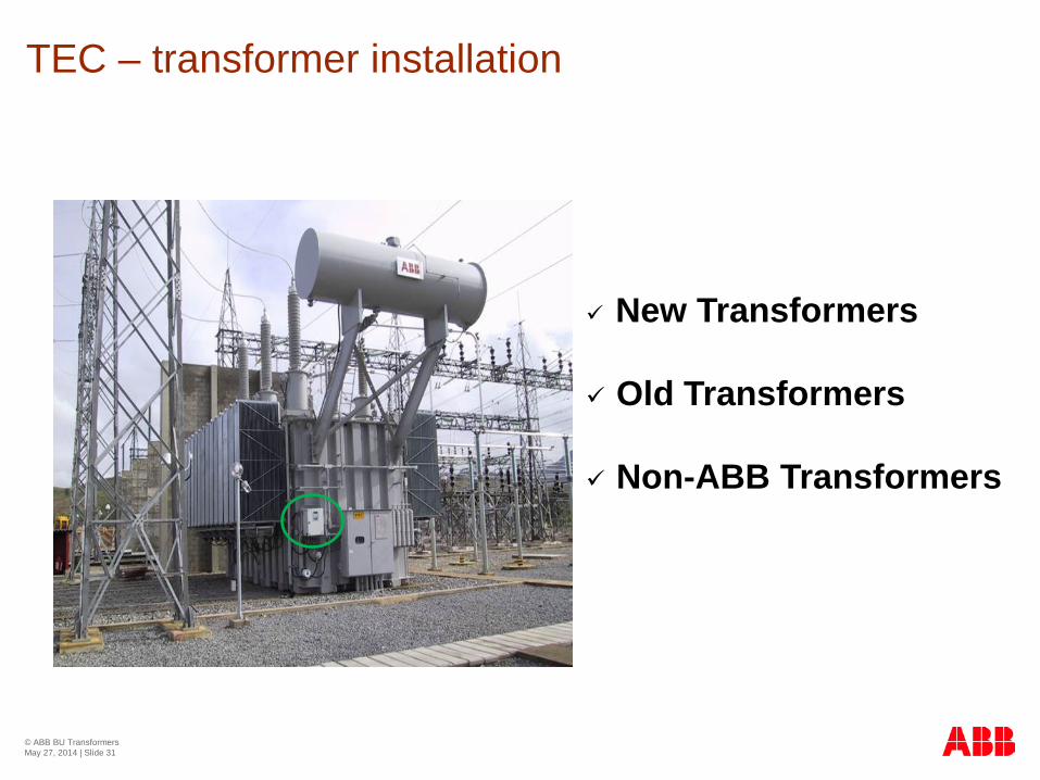
New Transformers
Old Transformers
Non-ABB Transformers
TEC – transformer installation
© ABB BU Transformers May 27, 2014 | Slide 31

TEC cabinet installation
1) Mount TEC on transformer.
2) Connect sensors and power supply according to drawings and connection tables.
3) Start system.
Note: The display indicates present status and events.
© ABB BU Transformers May 27, 2014 | Slide 32
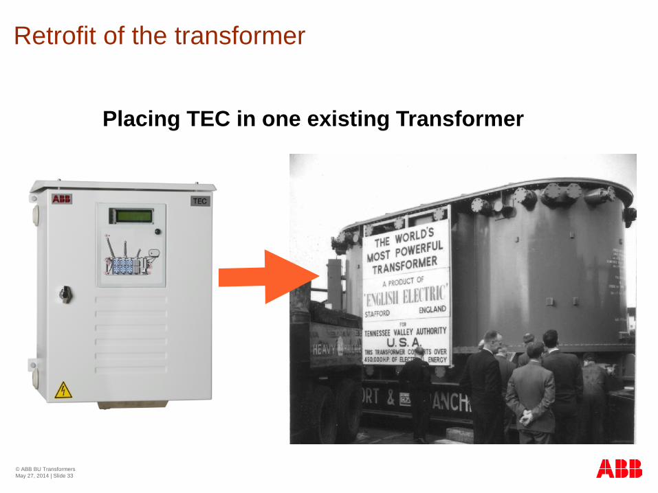
Placing TEC in one existing Transformer
Retrofit of the transformer
© ABB BU Transformers May 27, 2014 | Slide 33

Sensors. Can any existing sensors or sensor pockets be used? New sensors, what type should be used? New sensors, where are they best placed?
Historical data. To be able to display correct ageing of transformer and contact wear on the tap-changer, it is necessary to program the TEC with historical data.
Feedback from coolers. To monitor the coolers, TEC need feedback signal from each cooler when it is active. Are there any free contacts on existing cooler starting contactors? If not, how can the feedback be provided?
Retrofit of the transformer RI2 losses high voltage winding kW 89.5 32.2RI2 losses low voltage winding kW 131.0 47.2RI2 losses tertiary winding kW N/A N/AEddy losses in high voltage winding kW 8.3 3.0Eddy losses in low voltage winding kW 9.55 3.4Eddy losses in tertiary winding kW N/A N/ACalculated values for type test AF AN (When applicable)
Top oil temperature rise °C 56.5 58Average oil temperature rise °C 41.5 49No load loss at test kW 124 124Load losses at test - 764 275Tap-changer position - -2X2.5%(2) -2X2.5%(2)Current high voltage winding A 510.5 306.3Current low voltage winding A 1600 960Current tertiary voltage winding A N/A N/AHot-spot temperature high volt. wind. °C 74.3 67.5Hot-spot temperature low volt. wind. °C 75.3 67.5Hot-spot temperature tertiary volt. wind. °C N/A N/ATemperature gradient high volt. wind. °C 17.8 (3) 9.5(3)Temperature gradient low volt. wind. °C 18.8(3) 9.5(3)Temperature gradient tertiary volt. wind. °C N/A N/AMass parametersCu-Mass of high voltage winding kgCu-Mass of low voltage winding kgCu-Mass of tertiary winding kgFree oil kgOil in insulation kgCore steel mass kgOther steel mass (tank, yoke plate, etc.) kgPaper mass kgType test values AF AN (When applicable)
Ambient temperature °CTop oil temperature rise °C
438
3337 kg/limbN/A999154000
67000
4461 kg/limb
89049
© ABB BU Transformers May 27, 2014 | Slide 34


