20


MEMOIR SERIES
MEMOIR SERIESThis R&D Memoir Series summarizes cumulative achievements made by Statoil researchers and their associates in key technical areas: care is thus taken to differentiate between achievements made by Statoil alone and those resulting from external cooperation. The intended readership is anyone with a technical overview of the petroleum industry. No specialist knowledge of the subject is required.
Other titles in this series are: Memoir 1 – Flow AssuranceMemoir 2 – Offshore Geophysical MethodsMemoir 3 – Offshore Produced Water ManagementMemoir 4 – Geological Reservoir Characterization
Introduction 3
The options 5
The Sleipner West gas fi eld 6
The Snøhvit and In Salah projects 12
Power plants 14
Carbon dioxide utilization 16
Tomorrow’s world 19
Selected bibliography Back cover
ABBREVIATIONS
BGS: British Geological SurveyBGR: Bundesanstalt für Geowissenschaften und RohstoffeBRGM: Bureau de Recherches Geologiques et MinieresCASTOR: CO2 Capture and Storage ProjectCCP: CO2 Capture ProjectEBI: Energy and Biodiversity InitiativeENCAP: Enchanced Capture of Carbon Dioxide projectGEUS: Geological Survey of Denmark and GreenlandIEA: International Energy AgencyIFP: Institut Français du PetroleIMN : Industrikraft Midt-Norge ASIPIECA: Intern. Petrol. Industry Environmental Conservation Assoc.IOR: Improved Oil RecoveryLNG: Liquefi ed Natural GasLPG: Liquefi ed Petroleum GasNERC: Natural Environment Research Council (UK)NGU: Norwegian Geological SurveyNITG-TNO: Netherlands Institute of Applied Geoscience (TNO)NTNU: The Norwegian University of Science and TechnologyPEL: Progressive Energy LimitedSACS: Saline Aquifer CO2 Storage ProjectSINTEF: Foundation for Scientifi c and Industrial Research at NTNU
Front cover: cartoon of natural hydrocarbon gas being produced from the Sleipner gas fi eld. Above: captured carbon dioxide being pumped into the overlying Utsira Formation for long-term storage. (Illustrations: Alligator Film/BUG.)
ACKNOWLEDGEMENTS
The authors are indebted to the following Statoil staff for providing information and/or reviewing the penultimate manuscript: Bjørn Berger, Ivar Brevik, Ola Eiken, Frede Cappelen, Aoued Kaddour, Hanne Lekva, Even Solbraa, Jan Åge Stensen, Trude Sundset and Tore A Torp. The keen support of Ingve R Theodorsen (Senior Vice President, Research and Technology) and Bjørn Engdal (Director, Corporate Strategic Technology) is also gratefully acknowledged.
Antony T Buller, Olav Kårstad* & Gelein de Koeijer* Designer: Bente Lie, GTS, Statoil Research Centre
Publisher: Statoil ASAPrinter: Øien & Indergaard
Publication date: April 2004*Contact for further information
CONTENTS

3
INTRODUCTION
INTRODUCTIONCost-effective carbon dioxide capture, storage and utilization are essential elements in reconciling the use of fossil fuels with environmental protection.
Climate changeCarbon dioxide gas (CO2) is a natural, fl uctuating component of the Earth’s atmosphere and has been present throughout most of geological time. However, since the industrial revolution the concentration has risen by about a third (from 280 to 370 parts per million) and may well reach at least twice the pre-industrial level by 2100.
Most of this increase is attributed to the burning of carbon-rich fossil fuels – coal, natural gas and oil – and is widely thought to be a contributory factor in trap-ping heat radiating from the earth’s surface. This, in turn, may lead to global warming – the greenhouse effect – and stimulate climate change. To what extent this may happen is not known: some say it will lead to disastrous consequences while others foresee relatively slight but noticeable variations. Either way, something has to be done about it.
The obvious answer is to increase energy effi ciency and rapidly convert to alternative energy sources, such as solar and wind power. But this is easier said than done. Switching to alternative sources will be a gradual process, because about 85% of the world’s present energy needs are being met by plentiful and relatively inexpensive fossil fuels. In contrast, non-fossil fuel energy sources are expensive, and onshore renewables need large land areas to produce even modest quantities of power (e.g. windmill parks).
A more pragmatic approach is to stabilize atmospheric concentrations gradually at or below 550 parts per
1 Emission trading gives indus-trial countries the opportunity to meet obligatory reductions in emissions by purchasing quotas from other industrial nations or by cutting emissions for them.
million. But this too is an enormous challenge, requiring a fi fty per cent reduction in CO2 emissions from projected levels by 2050. New technologies are therefore needed to lower the cost of alternative energy sources, strengthen the removal and storage of CO2 from today’s fossil-fuelled industries, and replace oil and coal by less carbon-intensive natural gas. Nevertheless, this is the more attractive proposition as it promises to allow present fossil-fuel industries and fossil-fuel rich countries to continue operating profi tably while giving time for alternative energy sources to realistically come to the fore.
Windmill park near Gøteborg, Sweden.(Photo: Asle Strøm.)
Statoil and climate policyFor Statoil the issue is not whether the world faces a climate problem or how severe it may be, but how harmful emissions may best be overcome. The Kyoto protocol is therefore acceptable as a good basis for a rational global policy, including the introduction of a broad-based system of emission trading1, as long it is tied to Kyoto mechanisms. Statoil also cooperates widely with other companies and authorities, and is a signifi cant player in global affairs through its member-ships of the World Business Council for Sustainable Development, the Energy and Biodiversity Initiative (EBI), and bodies such as the IEA Greenhouse Gas R&D Programme and the IPIECA.
At home our specialists keep abreast of the latest developments in scientifi c knowledge about the greenhouse effect, and the social, economic and competitive impact of climate policies aimed at the
4
INTRODUCTION
Research history in briefOne of our earliest engagements in CO2 capture and storage was in the late 1980s when the Continental Shelf Institute4 was commissioned to carry out a pilot study on environment-friendly gas power and CO2 injection for improved oil recovery.
Similar research began at the Statoil Research Centre in 1989, but it was not until the early 1990s that internal activities really began to intensify.
In 1992 Statoil joined forces with Kværner Process Systems, NTNU and SINTEF to examine whether membrane technology for capturing CO2 from power station emissions would lead to signifi cant weight, space and cost reductions.
At about the same time, Statoil and partners decided that excessive amounts of CO2 contained in natural gas from the offshore Sleipner fi eld should be stripped off and injected into a saline aquifer situated above the hydrocarbon reservoirs. The primary goal was long-term storage to protect the natural environment.
To learn as much as possible from the Sleipner case, Statoil and the IEA Greenhouse Gas R&D Programme organization set up the European Commission’s SACS5 project (phases 1 and 2, 1998-2003), which led to the Sleipner experience becoming a truly multinational
concern with global applications in mind. The present CO2 Store project (2003-2005) is essentially a SACS extension, addressing long-term predictions of the aquifer’s behaviour and the transfer of approaches and methods to onshore and nearshore industrial sites.
The aims of the complementary, BP-coordinated CO2 Capture Project (2001 - 2003) were to reduce capture costs by more than 50 per cent at existing plants and by 75 per cent at new ones. Emphasis was placed on the development and qualifi cation of technology for capturing CO2 emitted by gas turbines and power stations. The project involved eight major oil and energy companies6, and included three distinct regional programmes run in the United States, Norway and the European Union. Statoil headed the Norwegian ‘Klimatek – NorCap’ contribution. And in common with the SACS initiative, the participants wished to demonstrate that CO2 storage is safe, measurable and verifi able.
Statoil is also looking at ways of transforming the CO2 challenge into viable business opportunities. One area under investigation is the transport of CO2 by ship and pipeline to mature offshore fi elds requiring gas-based improved oil recovery (IOR) programmes. The idea is to use CO2 instead of hydrocarbon gas as an oil-miscible component to improve sweep effi ciency.
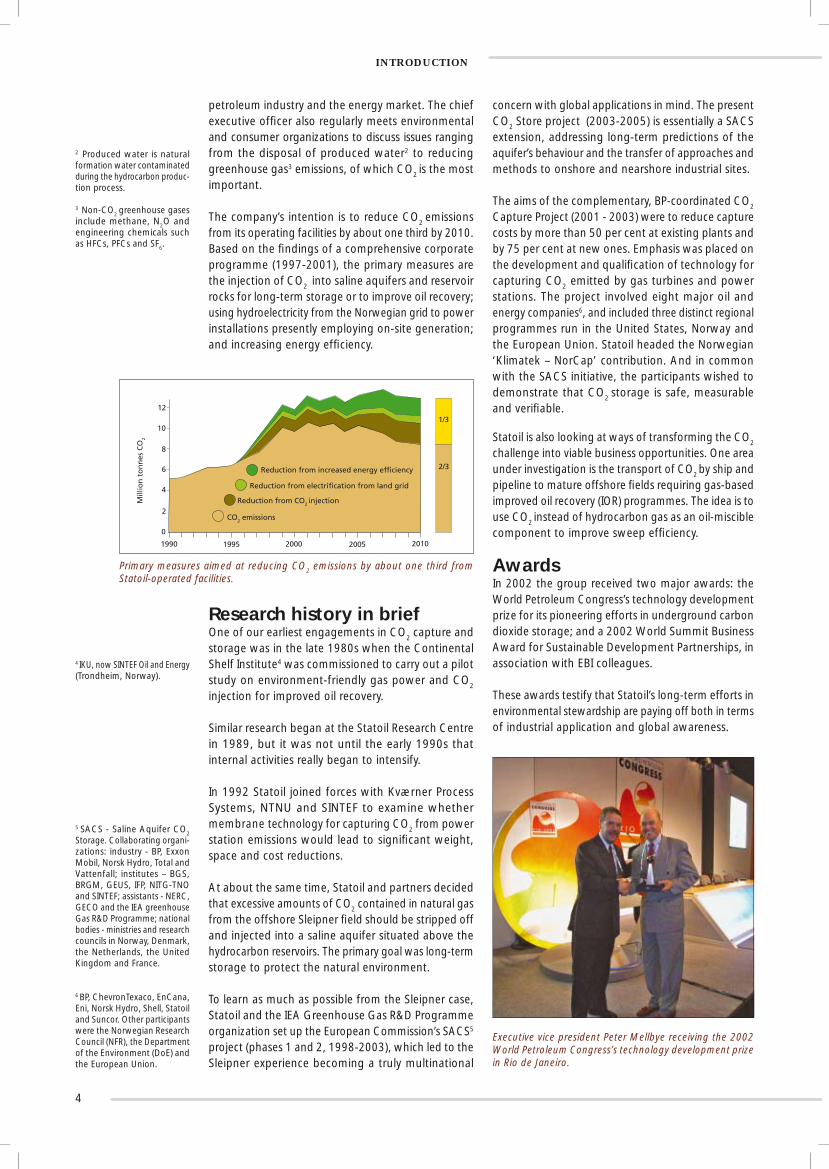
AwardsIn 2002 the group received two major awards: the World Petroleum Congress’s technology development prize for its pioneering efforts in underground carbon dioxide storage; and a 2002 World Summit Business Award for Sustainable Development Partnerships, in association with EBI colleagues.
These awards testify that Statoil’s long-term efforts in environmental stewardship are paying off both in terms of industrial application and global awareness.
4 IKU, now SINTEF Oil and Energy (Trondheim, Norway).
5 SACS - Saline Aquifer CO2 Storage. Collaborating organi-zations: industry - BP, Exxon Mobil, Norsk Hydro, Total and Vattenfall; institutes – BGS, BRGM, GEUS, IFP, NITG-TNO and SINTEF; assistants - NERC, GECO and the IEA greenhouse Gas R&D Programme; national bodies - ministries and research councils in Norway, Denmark, the Netherlands, the United Kingdom and France.
6 BP, ChevronTexaco, EnCana, Eni, Norsk Hydro, Shell, Statoil and Suncor. Other participants were the Norwegian Research Council (NFR), the Department of the Environment (DoE) and the European Union.
petroleum industry and the energy market. The chief executive offi cer also regularly meets environmental and consumer organizations to discuss issues ranging from the disposal of produced water2 to reducing greenhouse gas3 emissions, of which CO2 is the most important.
The company’s intention is to reduce CO2 emissions from its operating facilities by about one third by 2010. Based on the fi ndings of a comprehensive corporate programme (1997-2001), the primary measures are the injection of CO2 into saline aquifers and reservoir rocks for long-term storage or to improve oil recovery; using hydroelectricity from the Norwegian grid to power installations presently employing on-site generation; and increasing energy effi ciency.
2 Produced water is natural formation water contaminated during the hydrocarbon produc-tion process.
3 Non-CO2 greenhouse gases include methane, N2O and engineering chemicals such as HFCs, PFCs and SF6.
Executive vice president Peter Mellbye receiving the 2002 World Petroleum Congress’s technology development prize in Rio de Janeiro.
Primary measures aimed at reducing CO2 emissions by about one third from Statoil-operated facilities.
0
2
4
6
8
10
12
1990 1995 2000 2005 2010
1/3
2/3Reduction from increased energy efficiency
Reduction from electrification from land grid
Reduction from CO2 injection
CO2 emissions
Mill
ion
to
nn
es C
O2

5
THE OPTIONS
THE OPTIONS Long-term oceanic and underground storage promises to help nature cope with excessive carbon dioxide emissions to the air – the latter being the most realistic solution, at least in the near future.
Trees and other plants use up vast quantities of CO2 by absorbing it as they grow and retaining it throughout their lifetimes: much is also taken up by seas and oceans. However, these natural mechanisms appear to be inadequate to constrain current levels of anthropogenic (man-made) emissions, especially with continuing denudation of the rain forests and the ravaging of fertile ground by sprawling urbanization. Clearly there is a pressing need for new measures to be introduced, such as the disposal of CO2 in the ocean and long-term underground storage.
The oceanic storage concept involves the bubbling of gas directly into the sea at concentrations low enough to avoid damaging surrounding ecosystems, and at suffi cient depths to ensure that it stays there. Vari-ous methods have been suggested, including droplet plumes emanating either from the outlets of deep pipelines linked to onshore CO2 pumping stations or from pipes dangled from CO2 transport ships. Other possibilities include the injection of CO2 from offshore pumping stations into abyssal depths to accumulate as stagnant lakes, and the dropping of solid CO2 into the sea in the form of dry ice.
Although oceanic storage offers the greatest storage capacity, there are major uncertainties about the environmental impact and retention times. Statoil is therefore no longer actively engaged in oceanic disposal storage research but closely follows the latest scientifi c developments.
Long-term underground (subsurface) storage is regarded as the more reliable solution, requiring CO2 to be injected into deeply buried geological formations. The main candidates are depleted oil and gas reservoirs, deeply buried saline aquifers and unminable coal seams.
The attraction of using depleted oil and gas reservoirs is obvious: they are proven traps; the reservoir geol-ogy is well known; and infrastructures can be readily adapted for CO2 transport and injection. Indeed, depleted hydrocarbon gas fi elds and saline aquifers have long been used on a commercial basis to inject, store and withdraw natural gas according to supply and demand. At present there are 595 underground storage sites worldwide, whose collective working gas storage capacity is equivalent to 11 per cent of the world’s consumption.
There are also innumerable saline aquifers around the world that could be used for long-term CO2 storage. In both cases – depleted reservoirs and saline aquifers – much of the injected gas will eventually dissolve in the formation water, while some may react with the minerals to form carbonate precipitates.
Cartoon showing various subsurface options for CO2
storage and utilization. (A CCP illustration modifi ed by Johnny Schumann.)
*One gigatonne or Gt is a thousand million tonnes.
An important storage issue is sealing capacity; that is, the ability of the overlying (cap) rocks to stop the CO2 from leaking out and rising back to the surface. To fulfi l this criterion, cap rocks should be almost impermeable, and ductile rather than brittle if natural and induced fractures are to be avoided. Onshore leakage can affect water supplies and devastate vegetation cover.
For coal seams, the theory is that injected CO2 will be permanently locked in the coal by adsorption while enhancing methane production by preferential displacement.
Rough IEA estimates of how much CO2 could be stored in these various geological options are >15 Gt* in unminable coal seams, 920 Gt in depleted oil and gas fi elds, and 400-10 000 Gt in deep saline aquifers. With the atmosphere today containing about 730 Gt of CO2, saline aquifers obviously hold considerable promise.
Onshore CO2-based improved oil recovery is an established practice, which is yet to be tried offshore (see p. 16).

6
THE SLEIPNER WEST GAS FIELDThe Sleipner asset notched up two world fi rsts in pursuit of environmental protection – large-scale offshore carbon dioxide separation and injection into a saline aquifer 1 000 metres below the seabed.
The Statoil-operated Sleipner West1 fi eld is one of the largest gas producers in the Norwegian sector of the North Sea, with a daily gas export capacity of 20.7 mil-lion cubic metres and a daily output of 60 000 barrels of stabilized condensate (light oil). It was discovered in 1974 close to the British/Norwegian sector divide and is linked to Sleipner East. Both fi elds are produced by a single operations organization.
Location map showng the Sleipner licence and areal extent of the Utsira Formation.
During fi eld development planning (1990), it was realized that the 4 to 9.5 per cent CO2 content in the natural gas would have to be reduced to less than 2.5 per cent if it were to be fed directly into sales gas pipelines to Europe. A small team of technical experts came up with the unprecedented idea of capturing the CO2 offshore and injecting it into a saline aquifer beneath the Sleipner installations. In this way, the Sleipner asset would minimize CO2 emissions – the prime motive – while avoiding environmental taxes2. Despite its pioneering nature, this became the partner-approved solution.
Of various possibilities, the Elf-patented separation process was selected for CO2 capture, because it was deemed cheaper to run and more compact than competing systems. One of the greatest chal-lenges, however, was to scale down the process plant suffi ciently so that it could be accommodated on a platform. Even so, the ‘miniaturized’ version of the extraction module weighed 8 200 tonnes – the heavi-est module ever to be lifted offshore – and measured 50 m x 20 m x 35 m.
UtsiraFormation
SleipnerLicense
SHETLANDISLANDS
ORKNEYISLANDS
SCOTLAND
DENMARK
NORWAY
Kristiansund
Molde
Ålesund
Florø
Bergen
Haugesund
Stavanger
Kristiansand
Lerwick
Aberdeen
Dundee
Edinburgh
U.K
.N
orw
ay
The Sleipner T gas treatment installation (left) linked by a bridge to the Sleipner A platform. (Photo: Øyvind Hagen.)
1 The present partners are ExxonMobil, Norsk Hydro and Total.
THE SLEIPNER WEST GAS FIELD
Carbon dixide capture and injection
The carbon dioxide content in the natural gas can now be kept below 2.5 per cent by increasing the amine circulation rate and total heat input
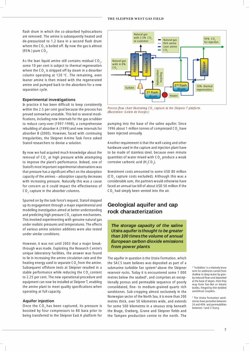
Carbon dioxide capture processThe fi rst stage in the Sleipner CO2 capture process
entails the mixing of an amine-water solution with the natural gas in two parallel columns (absorbers A and B), both of which are kept at high pressure (100 bara3) and moderate temperature (60 - 70 oC). The amine – an organic compound derived from ammonia – selectively absorbs the CO2 by weak chemical bond-ing and separates out at the bottom of the columns. Thereafter it is transferred via a turbine to a 15 bara
3 Bara – bar absolute (not to be confused with barg – bar gauge).
By the time the fi eld came on stream in 1996, the Sleipner organization had notched up two world fi rsts: the installation of a large-scale offshore CO2 extraction plant at the Sleipner T (Treatment) platform; and the facilities for saline aquifer injection from the Sleipner East A platform.
2 At this time the Norwegian government was discussing climate change and the pos-sibility of introducing a national carbon tax. The latter became law in 1991 and currently stands at USD 40 per tonne.
7
Process fl ow chart illustrating CO2 capture at the Sleipner T platform. (Illustration: Gelein de Koeijer.)
Experimental investigationsIn practice it has been diffi cult to keep consistently within the 2.5 per cent goal because the process has proved somewhat unstable. This led to several modi-fi cations, including new internals for the gas scrubber to reduce carry-over (1997-1998), a comprehensive rebuilding of absorber A (1999) and new internals for absorber B (2000). However, faced with continuing irregularities, the Sleipner Amine Task Force asked Statoil researchers to devise a solution.
By now we had acquired much knowledge about the removal of CO2 at high pressure while attempting to improve the plant’s performance. Indeed, one of Statoil’s most important experimental observations was that pressure has a signifi cant effect on the absorption capacity of the amines – adsorption capacity decreases with increasing pressure. Naturally this was a cause for concern as it could impact the effectiveness of CO2 capture in the absorber columns.
Spurred on by the task force’s request, Statoil stepped up its engagement through a major experimental and modelling investigation aimed at better understanding and predicting high pressure CO2 capture mechanisms. This involved experimenting with genuine natural gas under realistic pressures and temperatures. The effects of various amine solution additives were also tested under similar conditions.
However, it was not until 2003 that a major break-through was made. Exploiting the Research Centre’s unique laboratory facilities, the answer was found to lie in increasing the amine circulation rate and the heating energy used to separate CO2 from the amine. Subsequent offshore tests at Sleipner resulted in a stable performance while reducing the CO2 content to 2.25 per cent. The new operational procedure and equipment can now be installed at Sleipner T, enabling the amine plant to meet quality specifi cations when operating at full capacity.
Aquifer injection Once the CO2 has been captured, its pressure is boosted by four compressors to 80 bara prior to being transferred to the Sleipner East A platform for
pumping into the base of the saline aquifer. Since 1996 about 1 million tonnes of compressed CO2 have been injected annually.
Another requirement is that the well casing and other hardware used in the capture and injection plant have to be made of stainless steel, because even minute quantities of water mixed with CO2 produce a weak corrosive carbonic acid (H2CO3).
Investment costs amounted to some USD 80 million (CO2 capture costs excluded). Although this was a considerable sum, the partners would otherwise have faced an annual tax bill of about USD 50 million if the CO2 had simply been vented into the air.
fl ash drum in which the co-absorbed hydrocarbons are removed. The amine is subsequently heated and de-pressurized to 1.2 bara in a second fl ash drum where the CO2 is boiled off. By now the gas is almost (95%) pure CO2.
As the lean liquid amine still contains residual CO2, some 10 per cent is subject to thermal regeneration where the CO2 is stripped off by steam in a desorber column operating at 120 oC. The remaining, even leaner amine is then mixed with the regenerated amine and pumped back to the absorbers for a new separation cycle.
Geological aquifer and cap rock characterization
The storage capacity of the saline Utsira aquifer is thought to be greater than 100 times the volume of annual European carbon dioxide emissions from power plants
The aquifer in question is the Utsira Formation, which the SACS team believes was deposited as part of a submarine turbidite fan system4 above the Sleipner reservoir rocks. Today it is encountered some 1 000 metres below the seabed5, and comprises an excep-tionally porous and permeable sequence of poorly consolidated, fi ne- to medium-grained quartz rich sandstones. Sub-cropping almost exclusively in the Norwegian sector of the North Sea, it is more than 200 metres thick, over 50 kilometres wide, and extends for some 500 kilometres in a sinuous strip beneath the Brage, Oseberg, Grane and Sleipner fi elds and the Tampen production centre to the north. The
4 ’Turbidites’ is a relatively loose term for sediments carried from shallow to deep water by grav-ity-induced fl ows and deposited at the base of slopes. Here they may form fan-like or lobate bodies, fringed by thin-bedded sand/mud couplets.
5 The Utsira Formation sand-stones have porosities between 24 and 40% and permeabilities between 1and 3 Darcy.
THE SLEIPNER WEST GAS FIELD
1st flash drum
2nd flash drum
Abso
rber
B
Abso
rber
A
Strip
per
1st flash drum
2nd flash drum
Ab
sorb
er B
Ab
sorb
er A
Stri
pp
er
Natural gaswith 2.5% CO2
to customer Natural gasRich amineLean amineCO2
95% CO2
for injection
Natural gaswith 4-9% CO2
Turbine
Hyd
roca
rbon
re
cycl
ing
Heater
10% thermalregeneration

8
aquifer’s areal coverage is thus about 26 000 square kilometres.
Delineation and mapping of the top of the forma-tion is particularly important for defi ning its closure. If aquifers form large domal structures, the CO2 will be constrained and slight structural uncertainties can be ignored. However, precise and detailed depth mapping is vital if they undulate gently, as at Sleipner where the top of the aquifer above the injection point is relatively fl at. This is because minor variations may have a major effect on CO2 movement (migration routes), areas of accumulation and overall storage potential.
The regional mapping was done using 2D seismic datasets, while more detailed work was carried out around the injection point using 3D seismic6. Petro-physical data from some 300 wells were also available for study, plus limited rock samples in the form of drill cuttings and cores. Much sedimentological, geochemical
and rock-mechanical research is still being done on the complex cap rock/overburden sequence, which at Sleipner is about 700 metres thick. A dedicated 9-metre core was cut from this interval in the summer of 2002.
Another consideration is the possible presence and continuity of faults running through the aquifer and cap rock along which CO2 may escape to the seabed. Fortunately, no signifi cant faults have been detected from the seismic surveys (also see below) .The injection process itself could lead to local microseismicity and/or the opening of incipient, pressure-induced fractures, but the required injection pressures at Sleipner are suffi ciently low for this to be regarded as unlikely.
Furthermore, current thinking suggests that the plasticity of the overburden is such that faults and fractures are unlikely to serve as escape conduits. In other words the sealing capacity appears to be good.
6 In 3D surveys, seismic lines are shot so close together that the data can be represented as seismic data ‘cubes’. In 2D surveys, seismic lines are often several kilometres apart, requiring geoscientists to interpret what goes on in between them.
Injection of CO2 into the Utsira Formation from the Sleipner A platform.(Illustration: David Fierstein.)
Seismic monitoring
Seismic monitoring has revealed no carbon dioxide leakage in the overburden
Another taxing question was whether the dynamic behaviour of the injected CO2 and its potential impact on cap rock integrity could be monitored using modern geophysical techniques, especially seismic. After much discussion, it was agreed that time-lapse seismic would probably be suitable, because the velocity of sound waves should be able to differentiate between salt water-bearing (higher velocity) and CO2-bearing (lower
velocity) sandstones. Time-lapse seismic, which is also known as 4D seismic, involves comparing the results of 3D seismic surveys repeated at considerable time intervals: differences between the survey results are attributed to fl uid and/or pressure changes.
Four seismic surveys have been conducted so far: a pre-SACS baseline survey in 1994 prior to CO2
injection and three monitoring surveys carried out in 1999, 2001 and 2002 during CO2 injection. The latter have not only successfully traced the injection of the CO2 and expansion of the ‘bubble’, but have also yielded extremely sharp images of the aquifer’s overall geometry, internal structure and fl ow behaviour. As expected, gravitational separation is the dominant physical process because of the CO2’s buoyancy.
THE SLEIPNER WEST GAS FIELD
9
Gravimetric aquifer monitoring
Time-lapse gravity can potentially be used to better determine carbon dioxide density and mass distribution
Although gravimetry has a lower spatial resolution than its seismic counterpart, repeated high precision microgravity monitoring potentially provides better constraints on CO2 density and mass distribution. It may also give an early warning signal if considerable amounts are escaping upwards through the overburden, as well as yielding relatively inexpensive information on the long-term dissolution of the CO2 in the formation water once injection has ceased.
Statoil’s latest offshore time-lapse gravity surveying technique is being used, having been successfully employed at the Troll fi eld to image and monitor changes in the (hydrocarbon) gas-water contact. Developed in association with Scripps (University of California, San Diego) and co-funded by the US Department of Energy, the state-of-the-art seafl oor
Sleipner A
A particularly striking result is that the distribution and migration paths of the CO2
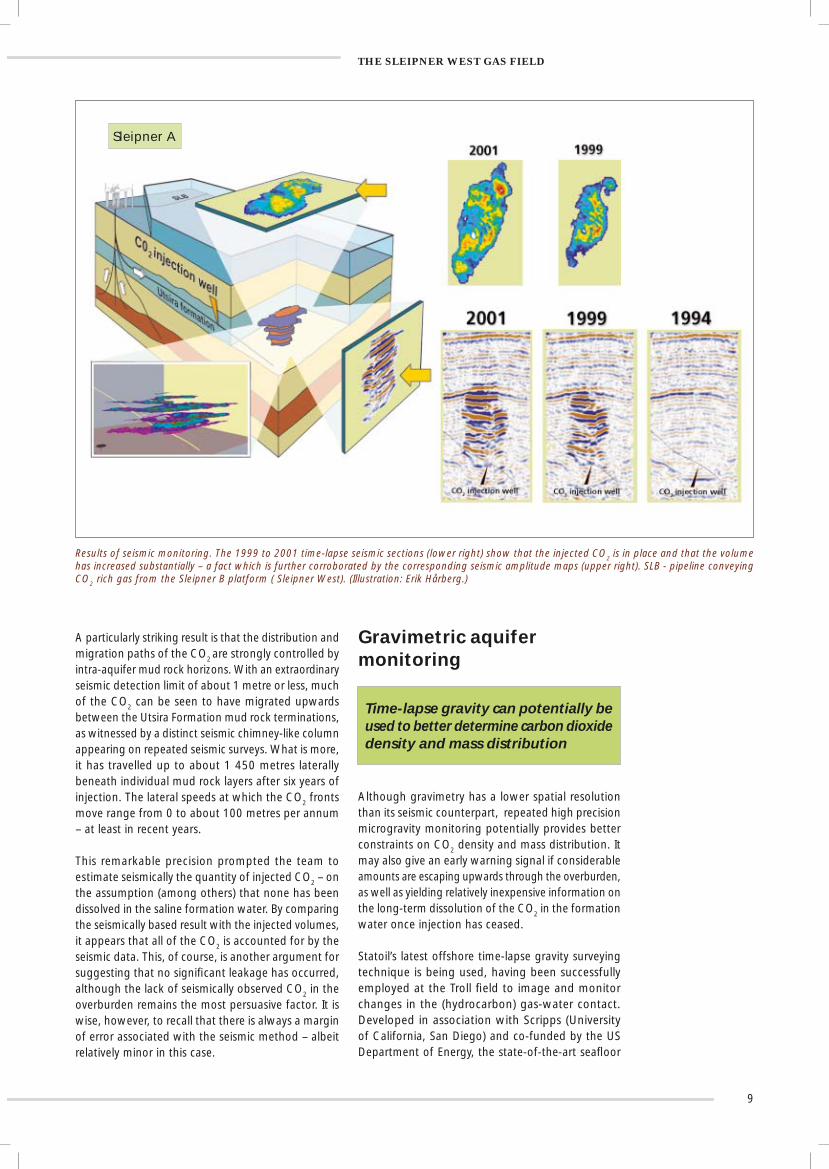
are strongly controlled by intra-aquifer mud rock horizons. With an extraordinary seismic detection limit of about 1 metre or less, much of the CO2 can be seen to have migrated upwards between the Utsira Formation mud rock terminations, as witnessed by a distinct seismic chimney-like column appearing on repeated seismic surveys. What is more, it has travelled up to about 1 450 metres laterally beneath individual mud rock layers after six years of injection. The lateral speeds at which the CO2 fronts move range from 0 to about 100 metres per annum – at least in recent years.
This remarkable precision prompted the team to estimate seismically the quantity of injected CO2 – on the assumption (among others) that none has been dissolved in the saline formation water. By comparing the seismically based result with the injected volumes, it appears that all of the CO2 is accounted for by the seismic data. This, of course, is another argument for suggesting that no signifi cant leakage has occurred, although the lack of seismically observed CO2 in the overburden remains the most persuasive factor. It is wise, however, to recall that there is always a margin of error associated with the seismic method – albeit relatively minor in this case.
THE SLEIPNER WEST GAS FIELD
Results of seismic monitoring. The 1999 to 2001 time-lapse seismic sections (lower right) show that the injected CO2 is in place and that the volume has increased substantially – a fact which is further corroborated by the corresponding seismic amplitude maps (upper right). SLB - pipeline conveying CO2 rich gas from the Sleipner B platform ( Sleipner West). (Illustration: Erik Hårberg.)

10
Principle of seafl oor gravity surveying. The Remotely Operated Vehicle - ROVDOG II - lowers the gravimeter onto concrete blocks placed on the seafl oor (Illustration: Erik Hårberg and Johnny Schumann.)
Aquifer fl ow modelling
Simulations suggest that the carbon dioxide ‘mega-bubble’ may reach its ultimate size after a few hundred years, thereafter shrinking and fi nally disappearing within a few thousand years
Whereas geophysical surveys are designed to determine rock and fl uid distributions, reservoir simulations are designed to predict how fl uids will behave with time. In a case like this, it is naturally wise to make a pre-injection simulation to test operational feasibility, as was done at Sleipner before the SACS project started.
The SACS team has subsequently built a detailed post-injection model to verify and improve the seismic and geological interpretation of the aquifer around the injection site; and a coarser, larger-scale model to predict CO2 migration over a period of several thousand years. The areas covered by the models are 7 square kilometres and 128 square kilometres, respectively. In both cases, the seismically inferred mud rock distributions were imported into the reser-voir models, because it is almost impossible to trace individual mudstone layers from well to well, even when they are close together. Calibration of the 3D repeated seismic data with a local reservoir model is thus a fundamental prerequisite.
Reservoir model of CO2 distribution after three years. (Source: SACS Best Practice Manual, 2003.)
gravimeter contains three gravity sensors and three pressure sensors, which enable the instrument to monitor small vertical changes in the seafl oor as well as small gravity changes. The gravitational accuracy is about 5x10⁻⁹ of the earth’s total gravity fi eld.
A seven by three kilometre baseline survey was obtained at Sleipner in August 2002, against which future surveys will be compared. So far the results have exceeded expectations: not only may it be possible to detect vertical changes in the seafl oor as small as 0.5 centimetres, but the time-lapse detection threshold may also be as low as 5 µGal7 – some 50 per cent better than that suggested by a pre-survey modelling exercise.
However, there are other considerations to be taken into account, such as the gravitational effect of further production from the underlying Sleipner gas-condensate reservoirs. The technique also depends on lowering
The results from the larger model suggest that most of the CO2 will eventually coalesce to form a single ‘mega-bubble’ beneath the cap rock a few years after injection has ceased. It will also gradually spread along the top of the salty formation water according to the local topography of the cap rock seal. This, however, must be tempered by the fact that CO2 will
the gravimeter onto separate concrete blocks installed on the seafl oor one at a time, although this did not prove to be a hindrance.
THE SLEIPNER WEST GAS FIELD
7 Gal – a unit of gravitational acceleration equal to one centimetre per second per second.

11
Further investigations
The ultimate objective is to combine chemical and fl ow-oriented modelling approaches for making reliable, long-term predictions
The main product of the SACS project is a compre-hensive Best Practice Manual (2003). This contains a suggested procedure for evaluating CO2 storage from a technical point of view, besides information aimed at satisfying authorities and the general public as to the feasibility, safety and reliability of the stor-age process.
The Sleipner case, which is being used as a full-scale natural laboratory, has yielded copious information on CO2 transport rates and geophysical properties, and has gone some way towards assessing the sealing capacity of the overburden.
These are considerable shorter-term achievements, of which the seismic monitoring is the most conspicuous. However, some of the most telling challenges still lie ahead, particularly the making of reliable long-term predictions, recalling that ‘long-term’ in this context refers to several hundred to several thousand years hence.
Ongoing investigations in the CO2 Store programme (2003-2005) include assessments of whether the free and dissolved CO2 remain in the host aquifer or migrate elsewhere; and whether the sealing capacity of the cap rock will be maintained, realizing that CO2-
diffuse from the ‘mega-bubble’ into the underlying brine column, a phenomenon that is usually ignored in standard reservoir simulations because it is extremely slow compared with other transport processes. But given time, the CO2-enriched brine on top of the column will become denser than that beneath, resulting in a downward fl ow compensated by convection plumes.
rich water is slightly acidic and may lead to mineral dissolution.
Other important issues are whether and how much of the injected CO2 can be permanently fi xed by chemical reactions and in what forms; and whether such chemical changes will impair porosity and per-meability, thereby reducing aquifer storage capacity while (possibly) improving retention. The conditions under which CO2 might ultimately be dissolved in its entirety are also receiving attention.
In short, the CO2 Store programme aims to extend the capabilities of two-phase (gas, water) reservoir simulators to better handle extremely long-term simulations, including the migration of CO2 in its dissolved form; and chemical-oriented modelling to predict the maximum potential for CO2 reaction with the Utsira Formation sediments and the cap rock.
The ultimate objective is to combine chemical mod-elling with the fl ow-oriented modelling approach of reservoir simulation to produce merged ‘chemical and reactive transport models’ constrained by geological and geochemical understanding – a highly ambitious undertaking. Geo-mechanical modelling is also coming to the fore in a number of related investigations.
This, in turn, will enhance dissolution and increase the probability of the CO2 remaining in the aquifer.
When dissolution is included in the simulations, the ‘mega-bubble’ will probably reach its ultimate size after a few hundred years, thereafter shrinking and fi nally disappearing within a few thousand years.
THE SLEIPNER WEST GAS FIELD
Simulated dissolution of CO2 in the saline water (brine) of the Utsira Formation. Red = supercritical CO2 ; green = CO2 rich brine. (Courtesy Erik Lindberg: a modifi ed illustration from that originally published in the SINTEF - NTNU Gemini magazine.)
Year 2021 Year 2412
Year 2621 Year 5019

12
THE SNØHVIT AND IN SALAH PROJECTS
THE SNØHVIT AND IN SALAH PROJECTSWith the addition of Snøhvit and the In Salah gas projects, Statoil is now involved in the world’s fi rst three carbon dioxide storage projects solely aimed at protecting the natural environment.
The Snøhvit development in the Barents Sea
Statoil and partners are planning the second largest offshore carbon dioxide storage project at Snøhvit based on the Sleipner West experience
Moving on from Sleipner West, Statoil and partners1 are planning the world’s second largest offshore CO2
storage project for the Snøhvit unit in the central part of the Hammerfest basin in the Barents Sea. The pro-duction area extends across seven unitized licences, covering the Snøhvit fi eld itself and the Albatross and Askeladd satellites. All three accumulations contain natural gas and small quantities of condensate. The Snøhvit unit is scheduled to come on stream in 2006, some 25 years after the fi rst gas discovery was made at Askeladd in 1981.
The unitized complex will be developed entirely using subsea production installations, linked by a record-breaking 143-kilometre multiphase fl ow pipeline to a processing and cryogenic gas liquefaction plant located at Melkøya – a small island outside Hammerfest.
The main product, LNG (liquefi ed natural gas), will be
Artwork of the multiphase pipeline linking Snøhvit and satellites to the LNG plant at Melkøya, northern Norway. (Illustration: Even Edland.)
The Snøhvit LNG project is the first oil and gas development in the environmentally sensitive Barents Sea and the fi rst LNG-based gas fi eld development in Europe. Furthermore, it is the fi rst Norwegian offshore development with no surface installations. With all of the production equipment residing in water depths of 250 to 345 metres, none will interfere with fi sh-ing activities. Operations will be remotely controlled from land.
The gas in all three accumulations contains 5 to 8 per cent CO2, which will have to be reduced to less than 50 parts per million prior to liquefaction. This means that about 700 000 tonnes of CO2 will have to be captured each year. Having reviewed several disposal options, it was decided that the CO2 will be injected into the Tubåen Formation – a deeply buried saline sandstone aquifer encountered at the Snøhvit fi eld about 2 600 metres below the seafl oor and about 60 metres beneath the main natural gas reservoir in the Stø Formation.
1 Petoro, Total, Gaz de France, Amerada Hess and RWE-DEA.
shipped to the USA and continental Europe in four purpose-built vessels, each 290 metres long and capable of carrying about 140 000 cubic metres of LNG in spherical tanks. Condensate and liquefi ed petroleum gas (LPG) will also be produced in relatively minor quantities. The LNG plant’s production capacity will be about 5.7 billion cubic metres of gas per year.
Snøhvit
Albatross
Askeladd

13
Geological cross-section showing the path of the Snøhvit CO2 injection well.
2 Ratio of total (net) sandstone thickness or volume to total (gross) thickness or volume.
3 Porosity 10 to 16 per cent; per-meability 130 to 890 mD.
The In Salah Gas project, central Algeria4
Plans are underway to reduce greenhouse gas emissions from the jointly operated In Salah Gas project by about 60 per cent
The third CO2 injection project concerns the jointly operated Sonatrach5-BP-Statoil In Salah dry gas project – the third largest of its kind in Algeria. The agree-ment covers the development of eight hydrocarbon gas discoveries in the Ahnet-Timimoum Basin in the central Saharan region of the country, and proposes to deliver 9 billion cubic metres per annum.
Some of the gas streams will contain CO2 concentra-tions as high as 10 per cent, whereas export sales gas specifi cations require a CO2 concentration of less than 0.3 per cent. To achieve this target, it has been estimated that some 1.2 million tonnes of CO2 will probably have to be stripped off and stored each year from mid-2004 when the gas comes on stream.
Prior to Statoil’s entry in 2003, BP and Sonatrach began searching for suitable subsurface sites close to the planned In Salah processing facilities that would be blessed with large storage potentials, reasonably good reservoir properties and good sealing capacities. Several possibilities emerged, ranging from storage sites at each fi eld to a single centralized facility. Of these various options, the latter solution was favoured because of the high cost and complexity associated with distributed subsurface storage.
BP and Sonatrach thereafter identifi ed the Krechba fi eld as the most appropriate candidate. Here the CO2
will be pumped through two or three horizontal wells directly into the aquifer section (below the gas-oil contact) around the northern periphery of the shallow Krechba sandstone reservoir. The reservoir rocks are of Carboniferous age and were deposited by a tidally
infl uenced estuary infi lling an incised valley system. Reservoir thicknesses vary from 5 to 24 metres within a broad, largely un-faulted, anticlinal fold. It is thought that the injected CO2 will only migrate upwards into the producing structure of the main fi eld once the fi eld has been fully depleted and abandoned.
From a rigorous evaluation using reservoir simulation models, BP estimated that breakthrough of the injected CO2 into central gas wells is unlikely to occur within the fi rst 15 years of production. By then, reductions in CO2 production from the other In Salah fi elds will have freed CO2 handling capacity at the Krechba surface facilities. The model, which will be up-dated, has also been used to identify well locations that satisfy criteria such as accessing connected sandstone volumes to accommodate the predicted quantities of CO2 and minimizing fl ow line distances.
4 Most of this section is based on BP and Sonatrach material in the public domain.
5 Sonatrach is the Algerian State Oil and Gas Company.
Sketch of CO2 storage at the Krechba fi eld, Algeria, showing that the CO2 will be injected into the water leg beneath the gas-water contact.
The Tubåen Formation contains some shale intervals that are diffi cult to correlate from well to well. Good interconnection between the sand bodies is thus anticipated. And with a thickness of about 47 to 75 metres, a net-to-gross ratio2 of 0.8 to 0.9, and good reservoir properties3, the formation should be able to cope easily with the estimated storage require-ment of about 23 million tons of CO2 during the 30-year lifetime of the Snøhvit project. The forma-tion is sealed by shaley caprocks of the intervening Nordmela Formation, which should be suffi cient to stop the injected CO2 from rising to contaminate the natural gas reservoirs above.
The separation process will again be amine-based and cost about USD 100 million. The main differ-ence between the Sleipner T and the Snøhvit plants is that the latter will be capable of stripping residual
CO2 from all of the lean amine solution after initial separation. And it goes without saying that Statoil’s world-class expertise gained at Sleipner is being fully exploited during the planning phase.
The separation plant will again be amine-based.
THE SNØHVIT AND IN SALAH PROJECTS
CO2 injection Gas production Gas
Oil
Shale
2300
2600
2500
2400
mMSL
Amine CO2 removal
Processing facilities
4 gas production wells 3 CO2 injection
wells
Gas
Water
Cretaceous sandstones and mudstones - 900 metres thick
Carboniferous mudstones ~950 metres thick
Carboniferous reservoir~20 metres thick

14
POWER PLANTSPast and present research is bringing the possibility of cost-effective carbon dioxide capture and storage from power plants ever closer.
Kårstø and Osaka pilot plants
Membrane technology promises to reduce weight and space at CO2 separation plants, as well as costs
Besides CO2 capture and storage from gas fi elds, Statoil has done much research on the cleaning of fl ue gas emissions from coal- and gas-fi red power plants. Although the power industry is the greatest contributor to global CO2 emissions, CO2 capture remains an elusive goal because of the low concen-trations of CO2 contained in exhaust fumes and the cost of removing them.
Statoil’s initial work was largely centred on a fl agship venture, which started in 1992 as a joint industry project with Kværner Process Systems, NTNU and SINTEF. The main aim was to investigate whether membrane contactors could replace the bulky amine towers currently used for CO2
absorption and desorption. Ongoing studies are concerned with verifying the current technology and making further improvements.
The membrane concept is simple: a gas absorption membrane serves as a contact device between a CO2-rich fl ue gas fl ow on one side and the fl ow of an absorption fl uid on the other. Separation occurs as the CO2 is selectively drawn through the membrane by the attraction of the absorption fl uid. The CO2 is then removed from the liquid at elevated temperature and pressure by essentially reversing the procedure so that the membrane acts as a desorption device. The
W L Gore and Associates (Gmbh) supplied designer membranes for installation at two major pilot plants – one in Norway (at Kårstø) and one in Japan (Osaka). The Japanese leg was in cooperation with the Kansai Electric Power Company, Mitsubishi Heavy Industries and the Carbon Dioxide Capture Project (see below). The main difference between the two investigations is that a conventional amine was used at Kårstø, while a recently developed alternative was tested at Osaka.
The main advantage of membrane technology is that it reduces weight and space by about 50 per cent, thus making it especially suitable for offshore CO2 as well as onshore capture. What is more, degradation of the absorbent can be reduced, and entrainment and foaming are totally avoided.
The results from both pilot plant tests are very encourag-ing, not only because of the weight/space advantages but also because of potential cost reductions.
Carbon dioxide capture project
The recent carbon dioxide capture project placed the challenge of reducing carbon dioxide emissions on the international agenda
While this work was underway, Statoil decided to widen its technological net by participating in several broad-based international studies, the latest and most comprehensive being the Carbon Dioxide Capture Project (CCP).
As stated in the Introduction (p. 4), the main aim of the project (2001-2003*) was to reduce the costs of CO2 separation and capture by more than 50 per cent for existing plants and by 75 per cent for new ones. Other objectives included ways of demonstrating to authorities and the public that CO2 storage is safe, measurable and verifi able, and to advance technolo-gies towards a ‘proof of concept’ stage.
* Although the project is officially over, several results are still being received.
Membrane separation principle. (Illustration: Kværner, MHI, Kansai.)
membranes are generally made from porous, hydro-phobic materials, although their exact constructions are far more complex.
POWER PLANTS
Exhaustwith CO2
Clean air
Leanamine
CO 2 richamine
Exhaust
Amine
Gas Membrane Liquid
Amine

15
Test plant at Kårstø for removing CO2 from fl ue gas. (Courtesy: AkerKvaerner.)
The CO2 Store project
Statoil and European partners are studying the possibility of extending Sleipner expertise to onshore industrial sites
Another investigation is currently assessing whether the Sleipner experience can be extended to onshore industrial sites. This is being done as part of the aforementioned CO2 Store project, in which four European locations have been earmarked for extensive feasibility studies: 1. Denmark: the Energi E2-operated power plant
and Statoil’s Kalundborg refi nery, which constitute the largest, single Danish CO2 emission point source accounting for some 6 million tonnes of CO2 per year. The power plant fuel is coal and orimulsion – a fuel consisting of a bitumen-in-water emulsion.
2. South Wales (UK): a prospective gasifi cation/combined cycle power station to be developed by Progressive Energy using a mixture of anthracitic coal and green petcoke. The proposed technical solution involves pre-combustion CO2 capture, possibly amounting to 1-2 million tonnes per year.
3. Part of the Trøndelag Platform: an area off the Norwegian coast that contains several CO2 point sources and where others are being planned.
4. Germany: the Schwarze Pumpe power plant operated by Vattenfall’s subsidiary VEAG (Vereinigte Energiwerke AG). The plant is fuelled with lignite and each block emits about 5 million tonnes of CO2
per year.
Both onshore and nearshore repositories will be inves-tigated, including those with large structural closures, depleted fi elds and regional deep saline aquifers.
The intention is that research will progress to such a stage that industry and national authorities can make an informed decision as to whether injection is a practical proposition in their respective areas. This, however, is not as straightforward as it seems, because judicial, safety and geological considerations will differ signifi cantly from place to place. The Sleipner experience will therefore have to be adapted to meet local conditions.
By the time this part of the CO2 Store project has run its course, the participants hope to offer a tool kit of various technologies and procedures that can be matched to suit the requirements of any deep saline aquifer, wherever it may be. The SACS 2003 Best Practice Manual will be updated accordingly.
Other projectsAlthough space limitations preclude extensive cover-age of all but the most eye-catching projects, it is important to mention that other collaborative ventures and proprietary in-house projects are systematically examining the entire range of available technologies. Among them, Statoil is a partner in three, integrated, multi-partner ventures which are partly funded by the European Union; namely, ENCAP, CASTOR and CO2Sink. These are concerned with pre-combustion, post-combustion and storage, respectively.
We are also jointly involved in several basic research projects, two of them dealing with CO2 capture and one with the use of CO2 for improved oil recovery (see p. 16). The aims are to elucidate fundamental physico-chemical phenomena in the hope of making signifi cant breakthroughs.
With such an immense scope, it is hardly surprising that most of the conclusions point to further research. Even so, there are many signifi cant results. For CO2 capture, the consortium developed a broad portfolio of technologies that will serve as the basis for the next generation, and has shown that all three of the main technical areas – pre-combustion, post-combustion and oxyfuel – have considerable potential for reduc-ing costs. Furthermore, a new set of tools has been developed for managing long-term CO2 storage, as well as a unique risk-based approach covering both aspects.
However, it was concluded that CO2 capture and storage from heat and power production is still too expensive in the light of current oil and gas prices and taxes. Moreover, no technology is emerging as a clear leader, although several promising areas may be on the brink of commercialization.
Perhaps the project’s most resounding achievement was that industries and governments came together in an international forum to promote strong technical leadership.
POWER PLANTS

16
CARBON DIOXIDE UTILIZATIONAssessing the viability of carbon dioxide-based miscible gas injection for improving oil recovery from offshore fi elds.
Of course it would be far better if the unwanted by-product could be converted into a green and profi table commodity.
Unfortunately, the world’s consumption of brewed and carbonated drinks falls well short of using up the vast quantities of excessive anthropogenic CO2, and the European market for so-called food grade CO2 is cur-rently running at only 2.7 million tonnes per year.
Other enticing possibilities are self-defeating in the sense that they normally involve the use of energy, thereby producing even more CO2.
One way of overcoming this is to use CO2 as a means of improving oil recovery (IOR). When the conditions are right, the injection of CO2 into a petroleum reservoir results in partial storage while improving the cash fl ow.
At the last count, some 70 or more onshore fi elds in the USA use CO2 -based miscible1 gas injection to squeeze more oil out of the reservoirs. Here there are
1 ‘Miscible’ refers to the ability of CO2 to mix with the oil.
2 In the USA 32 million tonnes of CO2 are acquired each year from natural sources and 11 million tonnes per year from industrial sources.
several natural sources2 of high grade, high pressure CO2, as well as a pipeline infrastructure linked to the fi elds in question.
A comprehensive study3 of 115 onshore fi elds concluded that the average improvement in the oil recovery factor is about 12 per cent for sandstone reservoirs and as high as 17 per cent for carbonates. Moreover, about 71 per cent of the injected CO2 (on average) remains in the reservoirs while back-produced4 CO2 is recovered and re-injected.
The next step – although a major one – is to transfer this decade-old practice from onshore to offshore, using industrial rather than natural sources of CO2.
The North Sea and even parts of the Norwegian Sea are regarded as potentially suitable targets, because numerous oil fi elds, gas processing sites and CO2 sources are relatively concentrated when compared with other offshore regions around the world.
But where will the CO2 come from?
Industrial sources and transport
Statoil is investigating the use of local carbon dioxide sources and the possibilities afforded by ship transport
The world’s industrial sources can be classified according to their CO2 concentration, and the costs of capturing high concentration sources are usually lower than those for low concentration sources.
s(M
t)
:
:
:
:
:
The most prolifi c sources are ammonia plants, hydro-gen plants, gas processing centres, cement factories, and iron and steel blast furnaces.
Another source for Statoil is its own gas processing sites (e.g. Sleipner and Snøhvit), where the gas consumer has already paid for the CO2 capture.
But how would the CO2 be transported to the fi elds?
On land, much CO2 is transported via pipelines and is thus a proven technology5.
This means that the adaptation of present and new pipelines systems is a feasible proposition in parts of the North and Norwegian Seas. However, another serious contender is the shipment of CO2 in tankers
Graph of CO2 emissions versus number and types of sources.
5 About 90 million tonnes/year of CO2 was transported by pipeline in the USA, according to an IEA Greenhouse Gas R&D Programme report in 2001.
3 Statoil commissioned SINTEF to perform this study.
4 Injected CO2 returning to the surface as part of the well stream.
CARBON DIOXIDE UTILIZATION

17
that are somewhat akin to those for transporting liquefi ed petroleum gas (LPG). In certain cases ship-ping may prove to be the cheaper alternative and will certainly be the more fl exible of the two solutions.
Statoil, SINTEF, Vigor AS and the Teekay Shipping Corporation6 have just completed a research project aimed at designing a suitable vessel. The planned ship is 177 metres long by 31 metres wide, and contains 4 to 6 tanks capable of holding 20 000 cubic metres of liquefi ed CO2 at around 7 bara and a temperature of - 50 ºC. One notable innovation is the development
Kårstø
Esbjerg
Brunsbüttel
Rotterdam
Antwerp
The ship (left) and map (right) of possible shipping routes around the eastern North Sea coastline.
Carbon dioxide-based improved oil recovery
Detailed screening studies show that several Statoil-operated fi elds may be suitable candidates
Over the years, Statoil has made enormous strides in improved oil recovery processes, not least the injec-tion of water and natural gas to sweep more oil out of reservoirs (e.g. WAG7) and the use of bacteria to mobilize more oil from pore surfaces (MIOR8). The IOR potential for Statoil-operated fi elds is thought to be signifi cant, particularly in the Tampen and Halten production centres off the southern and mid-Norwegian coast.
The possibility of using CO2 instead of natural gas has long been discussed, but it is only during the last fi ve years that the topic has received rigorous attention. The question is not whether CO2-based IOR is feasible – this has already been proved on land – but whether it is viable for the specifi c conditions encountered in the North Sea.
The general principle is broadly the same as that for natural gas-based techniques, bearing in mind that CO2 under elevated pressure and temperature is far denser than natural gas. After natural (primary) depletion9 and (secondary) water injection, CO2 can be injected into reservoirs where it mixes with the remaining oil and pushes a bank of additional oil towards production wells. CO2 injection is sometimes referred to as a tertiary recovery process. Principle of CO2-based improved oil recovery.
7 WAG – Water-Alternating-Gas.
8 MIOR – Microbial Improved Oil Recovery.
of equipment for directly discharging liquefi ed CO2 at production platforms. The ship is also designed as a multi-purpose carrier suitable for transporting LPG and similar products.
Having weighed up the relative costs of initially supplying about 10 million tonnes of CO2 by pipeline or ship, Statoil believes that both alternatives could be involved either separately or in combination.
But what about the technical and economic viability of offshore CO2-based improved oil recovery?
Many of the determining factors are common to any CO2-based IOR project whether on land or at sea: others, however, are peculiar to the offshore operating environment.
On one side of the equation is cost, where gross and net values of additional oil have to be balanced against operational and investment expenditure. Examples include the importation of vast quantities of CO2, its mode of transport, and the distances involved. Platform modifi cations also come into the picture, including the construction of production and injection systems and facilities for handling back-produced CO2.
On the other side of the equation are technical consid-erations; for example, well coverage and drainage areas,
9 In the North and Norwe-gian Seas water injection is carried out straight away, as natural depletion is relatively ineffective.
CO2 injection well Production well
CO2Miscible
zoneOil
bankAdditional
oil recovery
6 Formerly the Statoil-owned Navion company.
CARBON DIOXIDE UTILIZATION
18
bearing in mind that distances between offshore wells are far greater than their onshore counterparts.
Other issues concern the ways in which the physical and chemical characteristics of the reservoir rocks and fl uids may be affected by CO2, and the infl uence of recovery processes and drainage strategies used earlier in the life of a fi eld.
The eventual challenge of injecting CO2 through sub-sea wells (i.e. those installed on the seabed) must also be taken into account now that subsea IOR is much in focus.
The Tampen area of the North Sea, showing the Gullfaks platforms (A, B and C) and satellites fl anked by Stafjord (left) and Snorre (upper). (Illustration: Thor Oliversen.)
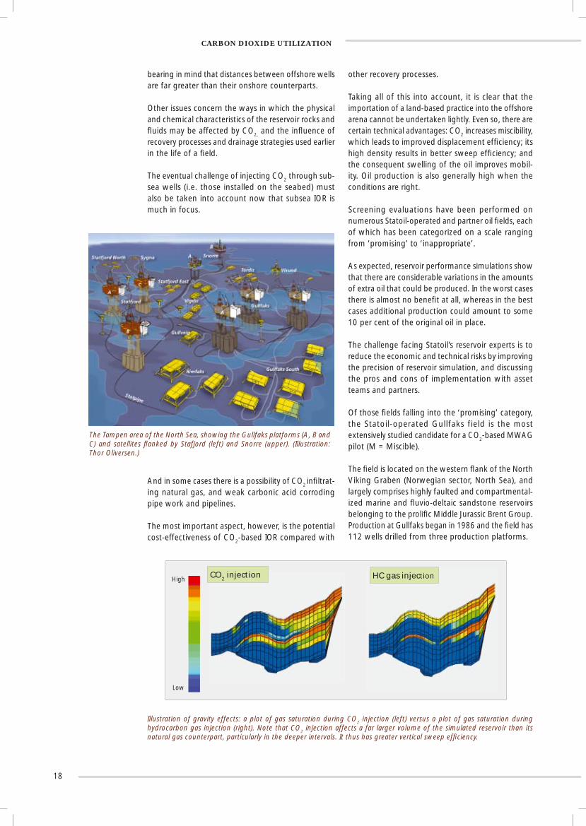
Illustration of gravity effects: a plot of gas saturation during CO2 injection (left) versus a plot of gas saturation during hydrocarbon gas injection (right). Note that CO2 injection affects a far larger volume of the simulated reservoir than its natural gas counterpart, particularly in the deeper intervals. It thus has greater vertical sweep effi ciency.
And in some cases there is a possibility of CO2 infi ltrat-ing natural gas, and weak carbonic acid corroding pipe work and pipelines.
The most important aspect, however, is the potential cost-effectiveness of CO2-based IOR compared with
other recovery processes.
Taking all of this into account, it is clear that the importation of a land-based practice into the offshore arena cannot be undertaken lightly. Even so, there are certain technical advantages: CO2 increases miscibility, which leads to improved displacement effi ciency; its high density results in better sweep effi ciency; and the consequent swelling of the oil improves mobil-ity. Oil production is also generally high when the conditions are right.
Screening evaluations have been performed on numerous Statoil-operated and partner oil fi elds, each of which has been categorized on a scale ranging from ‘promising’ to ‘inappropriate’.
As expected, reservoir performance simulations show that there are considerable variations in the amounts of extra oil that could be produced. In the worst cases there is almost no benefi t at all, whereas in the best cases additional production could amount to some 10 per cent of the original oil in place.
The challenge facing Statoil’s reservoir experts is to reduce the economic and technical risks by improving the precision of reservoir simulation, and discussing the pros and cons of implementation with asset teams and partners.
Of those fi elds falling into the ‘promising’ category, the Statoil-operated Gullfaks field is the most extensively studied candidate for a CO2-based MWAG pilot (M = Miscible).
The fi eld is located on the western fl ank of the North Viking Graben (Norwegian sector, North Sea), and largely comprises highly faulted and compartmental-ized marine and fl uvio-deltaic sandstone reservoirs belonging to the prolifi c Middle Jurassic Brent Group. Production at Gullfaks began in 1986 and the fi eld has 112 wells drilled from three production platforms.
CARBON DIOXIDE UTILIZATION
High
Low
CO2 injection HC gas injection

19
TOMORROW’S WORLD
TOMORROW’S WORLDStatoil is working towards a vision of carbon dioxide-free energy from fossil fuels and excellence in environmental stewardship.
Over the years Statoil has developed a vision of where oil and natural gas may be headed. Although subject to market and political fl uctuations, a plausible 21st century scenario is that fossil fuels will remain the prime energy sources while electricity and hydrogen will increasingly become the energy carriers. Our aim is to prepare for these eventualities and provide clean, energy-effi cient solutions for our customers.
Compared with oil, natural gas is cleaner, lighter, and burns more effi ciently. It can also be distributed through a network of pipes in a far less conspicuous fashion, and is the fastest growing fossil fuel and the primary choice for electricity generation. With an ever-increasing abundance of natural gas, it is hardly surprising that the company sees this as the source for both electricity and hydrogen*. In both of these cases the gas has to be decarbonized, which means that our world-class expertise in CO2 management is destined to play an even greater role.
Statoil’s intention is to intensify its efforts in developing and qualifying commercial cost-effective technology for these purposes. Indeed, the possibility already exists for testing CO2 capture technologies and the effi ciency of power and heat generation from natural gas using existing experimental facilities at the Research Centre.
We also hope to take part in the development of a hydrogen demonstration plant (including a reformer) for hydrogen production, storage, and delivery for fuel cells incorporated in cars and buses.
Recognizing the need for stronger national and international public policies and educational efforts to accelerate the process, we are stepping up our campaign to highlight the desirability of such devel-opments through the media, specialist seminars and conferences, trade exhibitions and the like.
And realizing that no petroleum company can go it alone, much of our research will be done with others through joint ventures with industry and governments.
To promote innovation, the group has recently established a business unit for ‘new energy’, which is continually on the look out for industrial applications arising from the latest research results.
Its mandate is to develop opportunities in sustainable production and renewable energy – including those arising from CO2 – as well as satisfying the emerging electricity and hydrogen economy.
The unit has already enjoyed considerable success as a business catalyst for renewables such as bio fuels, electricity generated from a tidally driven turbine (akin to a submerged windmill), and combined heat and power production using highly effi cient micro-energy stations.
In short, Statoil’s plan is to reduce the costs of CO2 capture; generate electricity and hydrogen from natural gas; consolidate its position in renewables; and demonstrate the wisdom of its chosen path to the authorities and society alike.
Cartoon illustrating how natural gas can be used to manufacture two CO2 -free energy carriers - electricity and hydrogen. Note the CO2 capture plant from which the CO2 can be injected into subsurface formations for long-term storage and/or CO2-based improved oil recovery. (Illustration: Arnfi nn Olsen and Olav Kårstad, c 1980.)
By now it should be abundantly clear that Statoil’s aspiration in sustainable development and environmental protection is to be among the best. Our present achievements suggest that we are well on the way.
*Statoil is also engaged in de-veloping the next generation of gas-to-liquids (GTL) technology to yield synthetic petrol and environment-friendly diesel. A forthcoming memoir on this subject is under discussion.

SELECTED BIBLIOGRAPHY
Statoil authored and co-authored publications largely related to Sleipner.
Arts, R., Brevik, I., Eiken, O., Sollie, R., Causse, E. and van der Meer, L. (2000). Geophysical methods for monitoring marine aquifer CO2 storage - Sleipner experiences. In: D.J. Williams et al. (eds.), Greenhouse Gas Control Technologies, CSIRO Publishing, Collingwood, Australia, pp. 366 – 371.
Arts, R., Eiken, O., Chadwick, R. A., Zweigel, P., van der Meer, L. and Zinszner, B. (2002). Monitoring of CO2 injected at Sleipner using time-lapse seismic data. GHGT-6 Conference, Kyoto 2002.
Arts, R., Eiken, O., Chadwick, R.A., Zweigel, P., van der Meer, L. and Kirby, G. Seismic monitoring at the Sleipner underground CO2 storage site (North Sea). Submitted to Geol. Soc. Spec. Publ. on Underground CO2 Storage.
Baklid, A., Korbul, R. and Owren, G. (1996). Sleipner Vest CO2 disposal, CO2 injection into a shallow underground aquifer. Presented at the 1996 SPE Annual Technical Conference and Exhibition, Denver, Colorado, USA, 6-9 October 1996, SPE Paper 36600.
Bolland O. and Undrum H. (2003). A novel methodology for comparing CO2 capture options for natural gas-fi red combined cycle plants. Advances in Environmental Research, 7 (4): 901-911, Elsevier Science Ltd.
Brevik, I., Eiken, O., Arts, R., Lindeberg, E. and Causse E. (2000). Expectations and results from seismic monitoring of CO2 injection into a marine aquifer. Presented at the 62nd EAGE meeting, Glasgow, Paper B-21.
Chadwick, R. A., Arts, R., Eiken, O., Kirby, G.A., Lindeberg, E. and Zweigel, P. 4D seismic imaging of a CO2 bubble at the Sleipner Field, central North Sea. Submitted to Geol. Soc. Spec. Mem. on 4D seismic.
Eiken, O., Brevik, I., Arts. R., Lindeberg, E. and Fagervik, K. (2000). Seismic monitoring of CO2 injected into a marine aquifer. Presented at the Calgary 2000 International Conference and 70th Annual Meeting, Calgary, Paper RC-8-2.
Hertzog, H., Eliasson, B. and Kårstad, O. (2000). Capturing greenhouse gases: sequestering carbon dioxide underground or in the deep ocean could help alleviate concerns about climate change. Scientifi c American, 282 (2): 72-79.
The following material is also available:
Milestones 2001Milestones 2002Milestones 2003
R&D Memoir 1 – Flow Assurance (2002)R&D Memoir 2 – Offshore Geophysical Methods (2002)R&D Memoir 3 – Offshore Produced Water Management (2003)R&D Memoir 4 – Geological Reservoir Characterization (2003)R&D Memoir 5 – Carbon Dioxide Capture, Storage and Utilization (2004)R&D Memoir 6 – Liquefi ed Natural Gas (in preparation) Hard copies: contact ‘Ktj Servicesenter’, Trondheim, +47 51992010. E-mail: [email protected] versions: Statoil Intranet: http://intranet.statoil.no/tek. (Statoil employees only)
Statoil, 4035 Stavanger, Norway, tel: +47 51990000Statoil Research Centre, 7005 Trondheim, Norway, tel: + 47 73584011
Statoil, Kårstø Metering and Technology Laboratory, 5001 Haugesund, Norway, tel: +47 52772200 Internet: http://www.statoil.com


![Influence of Transonic Flutter on the Conceptual Design of ......V? = Wing-perpendicularvelocity a = Acceleration b = Wingspan ... subsonic, and supersonic flow. Theodorsen [10],](https://static.documents.pub/doc/80x56/5e88fb902e59b70b946d6699/influence-of-transonic-flutter-on-the-conceptual-design-of-v-wing-perpendicularvelocity.jpg)


