18
XtraDrive XtraDrive XtraDrive XtraDrive XtraDrive XtraDrive XtraDrive EN DE ES FR IT AC SERVO DRIVES XtraDrive

XtraDrive XtraDriveXtraDrive
XtraDriveXtraDrive
XtraDrive XtraDrive
EN
DE
ES
FR
IT
AC SERVO DRIVESXtraDrive

2 YASKAWA XtraDrive
P3 30 W50 W
100 W200 W400 W
P5010204
750 W1.0 kW1.5 kW2.0 kW
08101520
500 W053.0 kW305.0 kW50
XD - 01 - MN -xx-01-EFeedback Option01 - Yaskawa serial, A&B
0A - A&B + Hall
Factory set optionblank - standard
D0 - Profibus DP
DL - Dual Loop
Electronic CAM enabledXtraDrive
Output capacity
Input voltageM: 230 V
T: 400 VExtended functionalityN: With CN10 connector for option units
S: No CN10 connector
XtraDrive
AC SERVO DRIVES
Model Designations

3
Filter
SGMAH / SGMPHServomotor
XtraDriveServo Drives
Terminal block
NS115
SW1
SW2
AR
CN6A
CN6B
CN4
Option unit
Analog monitor cable
Linear servomotorwith iron core
Linear scale
Serial converter
SGMGH / SGMSH / SGMUH Servomotor
Encoder cable
Encoder cable
Encoder cable
Power cable
Power cable
Power cable
General purpose cable
I/Osignals
Personal computer (PC)
SGL LINEARServomotor
PROFIBUS network
(XtraDrive models withembedded PROFIBUS)
Ratings
XtraDrive is an intelligent servo drive with integrated controller and network connectivity.
NCT. Patented non-linear algorithm for tight control:• Non-linear control, adaptive feed-forward algorithm and digital processing of encoder • pulses, provide both small tracking error and zero settling timeIncreased throughput and reduced influence of external perturbations•
Very low tracking error with no overshoot and zero settling time• Supports different servo motor encoder types• PROFIBUS DP embedded in the drive available• XtraDrive model available with electronic CAM• The ideal drive for linear motor control• Fast hardware registration input• Intuitive text programming language• Automatic tuning of servo parameters for optimal settling time• Integrated Oscilloscope available via XtraWare software tool•
Features
230 VAC single-phase 30 W to 1.5 kW (4.77 Nm)• 400 VAC three-phase 0.5 kW to 5.0 kW (28.4 Nm)•
System Configuration

XtraDriveXtraDrive
XtraDriveXtraDrive
XtraDriveXtraDrive XtraDrive
XtraDrive XtraDrive
XtraDrive
4 YASKAWA XtraDrive4 YASKAWA XtraDrive
XtraDrive
XtraDrive
XtraDrive
Servo motor Servo driveVoltage Rated torque Capacity 230 V (1-phase) 230 V (1-phase)
w PROFIBUS 400 V (3-phase) 400 V (3-phase)
w PROFIBUS Sigma-II series motors (refer to the Sigma-II rotary motor catalog for details)SGMAH (3000 min-1) 230 V 0.0955 Nm 30 W XD-P3-MN01-¡ XD-P3-MSD0-¡ - -
0.159 Nm 50 W XD-P5-MN01-¡ XD-P5-MSD0-¡ - -0.318 Nm 100 W XD-01-MN01-¡ XD-01-MSD0-¡ - -0.637 Nm 200 W XD-02-MN01-¡ XD-02-MSD0-¡ - -1.27 Nm 400 W XD-04-MN01-¡ XD-04-MSD0-¡ - -2.39 Nm 750 W XD-08-MN¡ XD-08-MSD0-¡ - -
400 V 0.955 Nm 300 W - - XD-05-TN¡ XD-05-TSD0-¡2.07 Nm 650 W - - XD-10-TN¡ XD-10-TSD0-¡
SGMPH (3000 min-1) 230 V 0.318 Nm 100 W XD-01-MN01-¡ XD-01-MSD0-¡ - -0.637 Nm 200 W XD-02-MN01-¡ XD-02-MSD0-¡ - -1.27 Nm 400 W XD-04-MN01-¡ XD-04-MSD0-¡ - -2.39 Nm 750 W XD-08-MN¡-¡ XD-08-MSD0-¡ - -4.77 Nm 1500 W XD-15-MN¡-¡ - - -
400 V 0.637 Nm 200 W - - XD-05-TN¡ XD-05-TSD0-¡1.27 Nm 400 W - - XD-05-TN¡ XD-05-TSD0-¡2.39 Nm 750 W - - XD-10-TN¡ XD-10-TSD0-¡4.77 Nm 1500 W - - XD-15-TN¡ XD-15-TSD0-¡
SGMGH (1500 min-1) 400 V 2.84 Nm 0.45 kW - - XD-05-TN¡ XD-05-TSD0-¡5.39 Nm 0.85 kW - - XD-10-TN¡ XD-10-TSD0-¡8.34 Nm 1.3 kW - - XD-15-TN¡ XD-15-TSD0-¡11.5 Nm 1.8 kW - - XD-20-TN¡ XD-20-TSD0-¡18.6 Nm 2.9 kW - - XD-30-TN¡ XD-30-TSD0-¡28.4 Nm 4.4 kW - - XD-50-TN¡ -
SGMSH (3000 min-1) 400 V 3.18 Nm 1.0 kW - - XD-10-TN¡ XD-10-TSD0-¡4.90 Nm 1.5 kW - - XD-15-TN¡ XD-15-TSD0-¡6.36 Nm 2.0 kW - - XD-20-TN¡ XD-20-TSD0-¡9.80 Nm 3.0 kW - - XD-30-TN¡ XD-30-TSD0-¡12.6 Nm 4.0 kW - - XD-50-TN¡ -15.8 Nm 5.0 kW - - XD-50-TN¡ -
SGMUH (6000 min-1) 400 V 1.59 Nm 1.0 kW - - XD-10-TN¡ XD-10-TSD0-¡2.45 Nm 1.5 kW - - XD-15-TN¡ XD-15-TSD0-¡4.9 Nm 3.0 kW - - XD-30-TN¡ XD-30-TSD0-¡6.3 Nm 4.0 kW - - XD-50-TN¡ -
Sigma linear motors (refer to the Sigma linear motors catalog for details)SGLGWLinear motors
230 V Refer to the linear motors catalog for details
SGLFWLinear motors
230 V,400 V
Refer to the linear motors catalog for details
SGLTWLinear motors
400 V Refer to the linear motors catalog for details
Servo motor / Servo drive combination

XtraDrive XtraDrive
XtraDrive
XtraDrive
XtraDriveXtraDriveXtraDrive
XtraDrive
XtraDrive XtraDrive
XtraDrive
XtraDrive
XtraDrive
XtraDrive
55
Single-phase, 230 V
Three-phase, 400 V
Servo drive type XD-P3-M¡ XD-P5-M¡ XD-01-M¡ XD-02-M¡ XD-04-M¡ XD-08-M¡ XD-15-M¡Applicable servo motor
SGMAH-¡ A3A¡ A5A¡ 01A¡ 02A¡ 04A¡ 08A¡ 15A¡SGMPH-¡ - - 01A¡ 02A¡ 04A¡ 08A¡ -
Bas
ic s
peci
ficat
ions
Max. applicable motor capacity W 30 50 100 200 400 750 1500Continuous output current Arms 0.44 0.64 0.91 2.1 2.8 5.7 11.6Max. output current Arms 1.3 2.0 2.8 6.5 8.5 13.9 28Input power Main circuit For single-phase, 200 to 230 VAC + 10 to -15%Supply Control circuit For single-phase, 200 to 230 VAC + 10 to -15%Control method Single phase full-wave rectification / IGBT / PWM / sine-wave current drive methodFeedback Serial encoder (incremental/absolute value)
Con
ditio
ns Usage/storage temperature 0 to +55 ˚C / -20 to 85 ˚CUsage/storage humidity 90%RH or less (non-condensing)Altitude 1000 m or less above sea levelVibration/shock resistance 4.9 m/s2 / 19.6 m/s2
Configuration Base mounted Approx. weight kg 0.8 1.1 1.7 3.8
Servo drive type XD-05-T¡ XD-10-T¡ XD-15-T¡ XD-20-T¡ XD-30-T¡ XD-50-T¡Applicable servo motor
SGMAH-¡ 03D¡ 07D¡ - - - -SGMPH-¡ 02D¡, 04D¡ 08D¡ 15D¡ - - -SGMGH-¡ 05D¡ 09D¡ 13D¡ 20D¡ 30D¡ 44D¡SGMSH-¡ - 10D¡ 15D¡ 20D¡ 30D¡ 40D¡/50D¡SGMUH-¡ - 10D¡ 15D¡ - 30D¡ 40D¡
Bas
ic s
peci
ficat
ions
Max. applicable motor capacity kW 0.45 1.0 1.5 2.0 3.0 5.0Continuous output current Arms 1.9 3.5 5.4 8.4 11.9 16.5Max. output current Arms 5.5 8.5 14 20 28 40.5Input power Main circuit For three-phase, 380 to 480 VAC + 10 to -15% (50/60 Hz)Supply Control circuit 24 VDC+15%Control method Three phase full-wave rectification / IGBT / PWM / sine-wave current drive methodFeedback Serial encoder (incremental/absolute value)
Con
ditio
ns Usage/storage temperature 0 to +55 ˚C / -20 to +85 ˚CUsage/storage humidity 90%RH or less (non condensing)Altitude 1000 m or less above sea levelVibration/shock resistance 4.9 m/s2 / 19.6 m/s2
Configuration Base mountedApprox. weight kg 2.8 3.8 5.5
Servo drive specifications
XtraDriveXtraDrive
XtraDriveXtraDrive
XtraDriveXtraDrive XtraDrive
XtraDrive XtraDrive
XtraDrive
6 YASKAWA XtraDrive6 YASKAWA XtraDrive
XtraDrive
XtraDrive
XtraDrive
Sp
eed
/to
rqu
e co
ntr
ol m
od
e
Per
form
ance
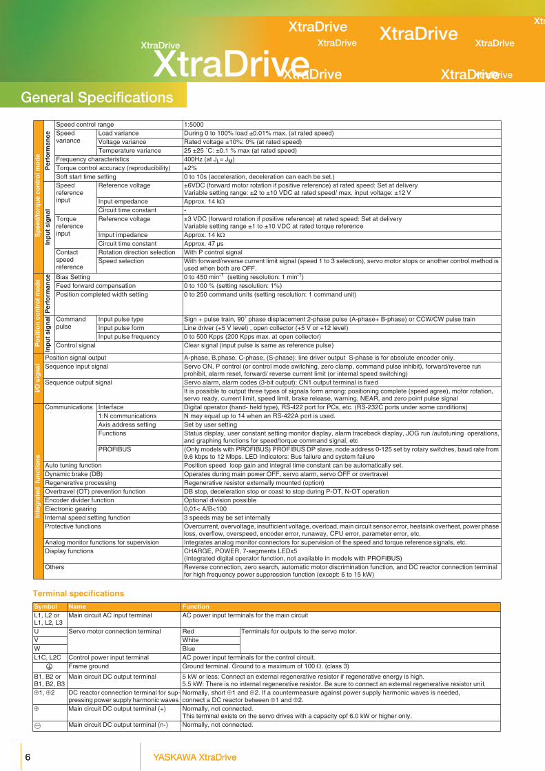
Speed control range 1:5000Speedvariance
Load variance During 0 to 100% load ±0.01% max. (at rated speed)Voltage variance Rated voltage ±10%: 0% (at rated speed)Temperature variance 25 ±25 ˚C: ±0.1 % max (at rated speed)
Frequency characteristics 400Hz (at JL= JM)Torque control accuracy (reproducibility) ±2%Soft start time setting 0 to 10s (acceleration, deceleration can each be set.)
Inp
ut
sig
nal
Speed reference input
Reference voltage ±6VDC (forward motor rotation if positive reference) at rated speed: Set at deliveryVariable setting range: ±2 to ±10 VDC at rated speed/ max. input voltage: ±12 V
Input empedance Approx. 14 kΩCircuit time constant -
Torque referenceinput
Reference voltage ±3 VDC (forward rotation if positive reference) at rated speed: Set at deliveryVariable setting range ±1 to ±10 VDC at rated torque reference
Imput impedance Approx. 14 kΩCircuit time constant Approx. 47 µs
Contact speed reference
Rotation direction selection With P control signalSpeed selection With forward/reverse current limit signal (speed 1 to 3 selection), servo motor stops or another control method is
used when both are OFF.
Po
siti
on
co
ntr
ol m
od
e
Per
form
ance Bias Setting 0 to 450 min-1 (setting resolution: 1 min-1)
Feed forward compensation 0 to 100 % (setting resolution: 1%)Position completed width setting 0 to 250 command units (setting resolution: 1 command unit)
Inp
ut
sig
nal Command
pulseInput pulse type Sign + pulse train, 90˚ phase displacement 2-phase pulse (A-phase+ B-phase) or CCW/CW pulse trainInput pulse form Line driver (+5 V level) , open collector (+5 V or +12 level)Input pulse frequency 0 to 500 Kpps (200 Kpps max. at open collector)
Control signal Clear signal (input pulse is same as reference pulse)
I/O s
ign
al
Position signal output A-phase, B.phase, C-phase, (S-phase): line driver output S-phase is for absolute encoder only.Sequence input signal Servo ON, P control (or control mode switching, zero clamp, command pulse inhibit), forward/reverse run
prohibit, alarm reset, forward/ reverse current limit (or internal speed switching)Sequence output signal Servo alarm, alarm codes (3-bit output): CN1 output terminal is fixed
It is possible to output three types of signals form among: positioning complete (speed agree), motor rotation, servo ready, current limit, speed limit, brake release, warning, NEAR, and zero point pulse signal
Inte
gra
ted
fu
nct
ion
s
Communications Interface Digital operator (hand- held type), RS-422 port for PCs, etc. (RS-232C ports under some conditions)1:N communications N may equal up to 14 when an RS-422A port is used.
Axis address setting Set by user settingFunctions Status display, user constant setting monitor display, alarm traceback display, JOG run /autotuning operations,
and graphing functions for speed/torque command signal, etcPROFIBUS (Only models with PROFIBUS) PROFIBUS DP slave, node address 0-125 set by rotary switches, baud rate from
9.6 kbps to 12 Mbps. LED Indicators: Bus failure and system failureAuto tuning function Position speed loop gain and integral time constant can be automatically set.Dynamic brake (DB) Operates during main power OFF, servo alarm, servo OFF or overtravelRegenerative processing Regenerative resistor externally mounted (option)Overtravel (OT) prevention function DB stop, deceleration stop or coast to stop during P-OT, N-OT operationEncoder divider function Optional division possibleElectronic gearing 0,01< A/B<100Internal speed setting function 3 speeds may be set internallyProtective functions Overcurrent, overvoltage, insufficient voltage, overload, main circuit sensor error, heatsink overheat, power phase
loss, overflow, overspeed, encoder error, runaway, CPU error, parameter error, etc.Analog monitor functions for supervision Integrates analog monitor connectors for supervision of the speed and torque reference signals, etc.Display functions CHARGE, POWER, 7-segments LEDx5
(Integrated digital operator function, not available in models with PROFIBUS) Others Reverse connection, zero search, automatic motor discrimination function, and DC reactor connection terminal
for high frequency power suppression function (except: 6 to 15 kW)
Terminal specifications
Symbol Name FunctionL1, L2 orL1, L2, L3
Main circuit AC input terminal AC power input terminals for the main circuit
U Servo motor connection terminal Red Terminals for outputs to the servo motor.V WhiteW BlueL1C, L2C Control power input terminal AC power input terminals for the control circuit.
Frame ground Ground terminal. Ground to a maximum of 100 Ω. (class 3)
B1, B2 orB1, B2, B3
Main circuit DC output terminal 5 kW or less: Connect an external regenerative resistor if regenerative energy is high.5.5 kW: There is no internal regenerative resistor. Be sure to connect an external regenerative resistor unit.
⊕1, ⊕2 DC reactor connection terminal for sup-pressing power supply harmonic waves
Normally, short ⊕1 and ⊕2. If a countermeasure against power supply harmonic waves is needed, connect a DC reactor between ⊕1 and ⊕2.
⊕ Main circuit DC output terminal (+) Normally, not connected.This terminal exists on the servo drives with a capacity opf 6.0 kW or higher only.
Main circuit DC output terminal (n-) Normally, not connected.
General Specifications
XtraDrive XtraDrive
XtraDrive
XtraDrive
XtraDriveXtraDriveXtraDrive
XtraDrive
XtraDrive XtraDrive
XtraDrive
XtraDrive
XtraDrive
XtraDrive
77
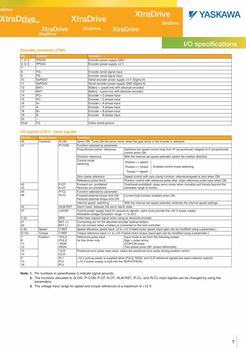
Encoder connector (CN2)
I/O signals (CN1) - input signals
Note: 1. Pin numbers in parentheses () indicate signal grounds.2. The functions allocated to /S-ON, /P-CON. P-OT, N-OT, /ALM-RST, /P-CL, and /N-CL input signals can be changed by using the
parameters. 3. The voltage input range for speed and torque references is a maximum of ±12 V.
Pin Symbol Function1, 2, 3 PPG0V Encoder power supply GND4, 5, 6 PPG5V Encoder power supply +5 V7 - -8 PS+ Encoder serial signal input9 PS− Encoder serial signal input10 SePG5V Serial encoder power supply +5 V (Sigma-II)11 SePG0V Serial encoder power supply GND (Sigma-II)12 BAT+ Battery + (used only with absolute encoder)13 BAT- Battery - (used only with absolute encoder)14 PC+ Encoder + C-phase input15 PC− Encoder − C-phase input16 A+ Encoder + A-phase input17 A− Encoder − A-phase input18 B+ Encoder + B-phase input19 B− Encoder − B-phase input20 - -Shell FG Cable shield ground
Pin No. Signal Name Function40 Common /S ON Servo ON: Turns ON the servo motor when the gate block in the inverter is released.41 /P CON Function selected by parameter.
Proportional control reference Switches the speed control loop from PI (proportional/ integral) to P (proportional) control when ON.
Direction reference With the internal set speed selected: switch the rotation direction.Control mode switching
Zero-clamp reference Speed control with zero-clamp function: referencevspeed is zero when ON.Reference pulse block Position control with reference pulse stop: stops reference pulse input when ON.
4243
P OTN OT
Forward run prohibited Reverse run prohibited
Overtravel prohibited: stops servo motor when movable part travels beyond the allowable range of motion.
4546
/P CL/N CL
Function selected by parameter. Forward external torque limit ONReverse external torque limit ON
Current limit function enabled when ON.
Internal speed switching With the internal set speed selected: switches the internal speed settings.44 /ALM RST Alarm reset: releases the servo alarm state.47 +24VIN Control power supply input for sequence signals: users must provide the +24 V power supply.
Allowable voltage fluctuation range: 11 to 25 V4 (2) SEN Initial data request signal when using an absolute encoder.2122
BAT (+)BAT (-)
Connecting pin for the absolute encoder backup battery.Do not connect when a battery is connected to the host controller.
5 (6) Speed V REF Speed reference speed input: ±2 to ±10 V/rated motor speed (input gain can be modified using a parameter .)9 (10) Torque T REF Torque reference input: ±1 to ±10 V/rated motor torque (input gain can be modified using a parameter.)781112
Position PULS/PULS SIGN/SIGN
Reference pulse inputfor line driver only
Input mode is set from the following pulses.Sign + pulse stringCCW/CW pulseTwo-phase pulse (90° phase differential)
1514
CLR/CLR
Positional error pulse clear input: clears the positional error pulse during position control.
31318
PL1PL2PL3
+12 V pull-up power is supplied when PULS, SIGN, and CLR reference signals are open-collector outputs (+12 V power supply is built into the SERVOPACK).
Position speed
Position torque
Torque speed
Enables control mode switching.
↔
↔
↔
I/O specifications
XtraDriveXtraDrive
XtraDriveXtraDrive
XtraDriveXtraDrive XtraDrive
XtraDrive XtraDrive
XtraDrive
8 YASKAWA XtraDrive8 YASKAWA XtraDrive
XtraDrive
XtraDrive
XtraDrive
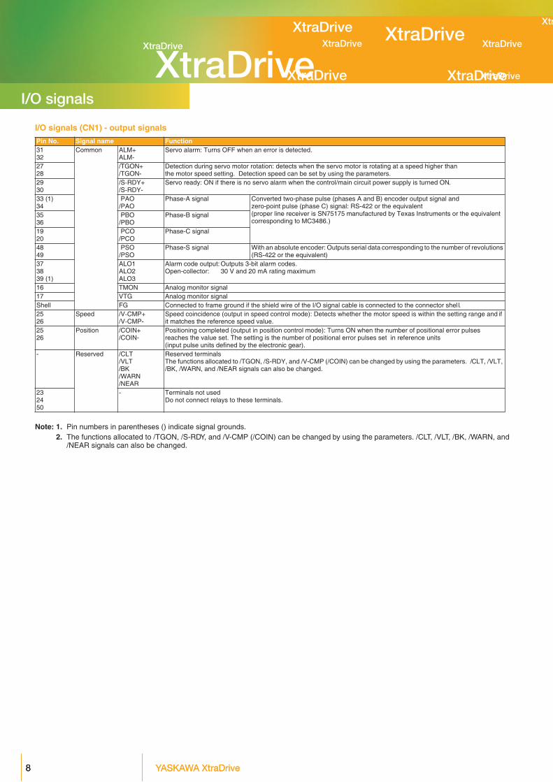
I/O signals (CN1) - output signals
Note: 1. Pin numbers in parentheses () indicate signal grounds.2. The functions allocated to /TGON, /S-RDY, and /V-CMP (/COIN) can be changed by using the parameters. /CLT, /VLT, /BK, /WARN, and
/NEAR signals can also be changed.
Pin No. Signal name Function3132
Common ALM+ALM-
Servo alarm: Turns OFF when an error is detected.
2728
/TGON+/TGON-
Detection during servo motor rotation: detects when the servo motor is rotating at a speed higher than the motor speed setting. Detection speed can be set by using the parameters.
2930
/S RDY+/S RDY-
Servo ready: ON if there is no servo alarm when the control/main circuit power supply is turned ON.
33 (1)34
PAO/PAO
Phase-A signal Converted two-phase pulse (phases A and B) encoder output signal and zero-point pulse (phase C) signal: RS-422 or the equivalent(proper line receiver is SN75175 manufactured by Texas Instruments or the equivalent corresponding to MC3486.)
3536
PBO/PBO
Phase-B signal
1920
PCO/PCO
Phase-C signal
4849
PSO/PSO
Phase-S signal With an absolute encoder: Outputs serial data corresponding to the number of revolutions (RS-422 or the equivalent)
373839 (1)
ALO1ALO2ALO3
Alarm code output: Outputs 3-bit alarm codes.Open-collector: 30 V and 20 mA rating maximum
16 TMON Analog monitor signal17 VTG Analog monitor signalShell FG Connected to frame ground if the shield wire of the I/O signal cable is connected to the connector shel l.2526
Speed /V CMP+/V CMP-
Speed coincidence (output in speed control mode): Detects whether the motor speed is within the setting range and if it matches the reference speed value.
2526
Position /COIN+/COIN-
Positioning completed (output in position control mode): Turns ON when the number of positional error pulses reaches the value set. The setting is the number of positional error pulses set in reference units (input pulse units defined by the electronic gear).
- Reserved /CLT/VLT/BK/WARN/NEAR
Reserved terminalsThe functions allocated to /TGON, /S-RDY, and /V-CMP (/COIN) can be changed by using the parameters. /CLT, /VLT, /BK, /WARN, and /NEAR signals can also be changed.
232450
- Terminals not usedDo not connect relays to these terminals.
I/O signals
XtraDrive XtraDrive
XtraDrive
XtraDrive
XtraDriveXtraDriveXtraDrive
XtraDrive
XtraDrive XtraDrive
XtraDrive
XtraDrive
XtraDrive
XtraDrive
99
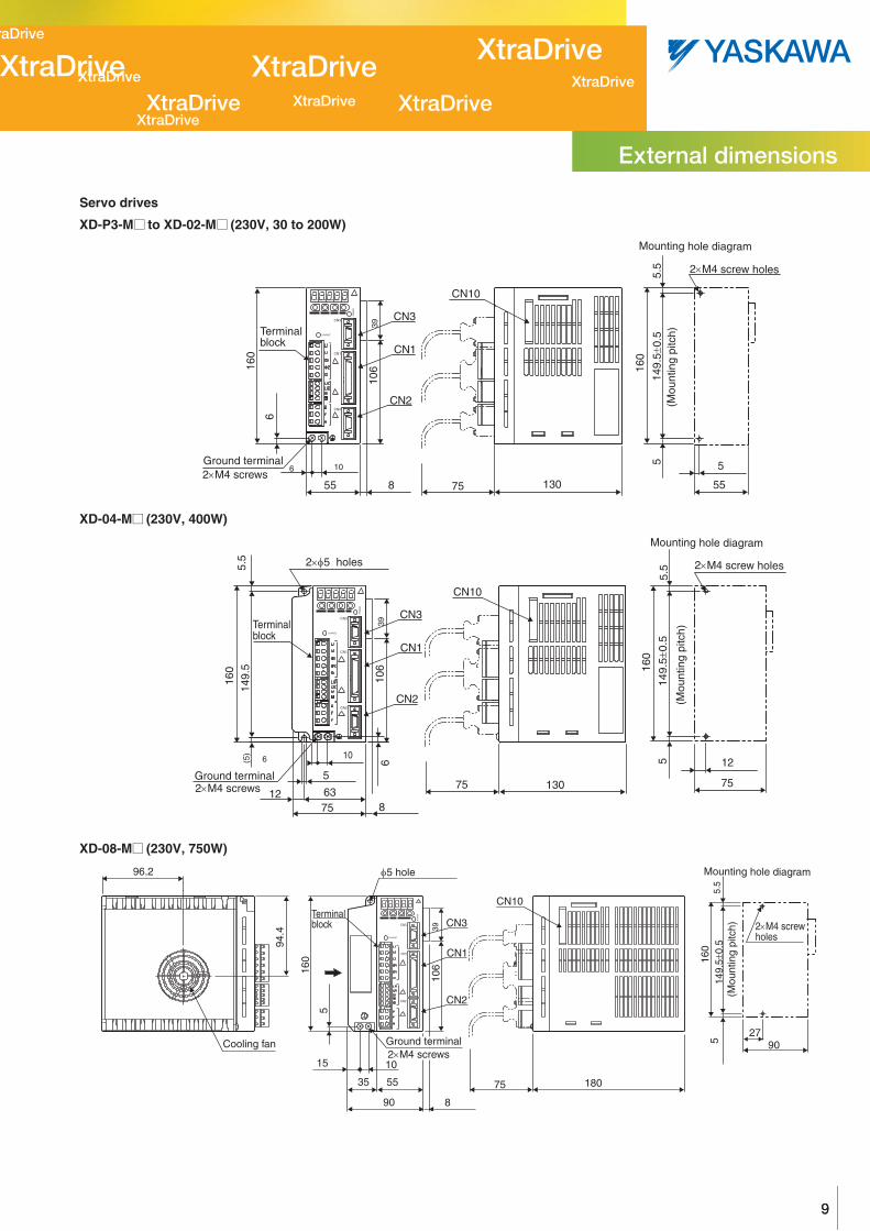
Servo drives
XD-P3-M¡ to XD-02-M¡ (230V, 30 to 200W)
XD-04-M¡ (230V, 400W)
XD-08-M¡ (230V, 750W)
Ground terminal2×M4 screws
(Mou
ntin
g pi
tch)
160
5
5.5
149.
5±0.
5
55
160
106
6
13075
5
8
2×M4 screw holes
Mounting hole diagram
Terminalblock
55
CN10
CN3
CN2
CN1
3910
6
CHARGE
PO
WE
R
CN3
CN1
CN2
149.
5±0.
5
12
75130
6
160
149.
55.
5
75
(5)
7512 63
5
6 10
5.5
160
8
2×φ5 holes
CN10
Ground terminal2×M4 screws
Terminalblock
5
2×M4 screw holes
Mounting hole diagram
(Mou
ntin
g pi
tch)
CN3
CN2
CN1
3910
6
CHARGE
PO
WE
R
CN3
CN1
CN2
CN3
94.4
90 27
149.
5±0.
516
05.
55
96.2
5
160
15 10
35 55
90
18075
Cooling fan
φ5 hole
CN2
CN1
39
8
106
CN10
CHARGE
2×M4 screwholes
(Mou
ntin
g pi
tch)
Mounting hole diagram
Terminalblock
Ground terminal2×M4 screws
CN3
CN1
PO
WE
R
CN2
External dimensions

XtraDriveXtraDrive
XtraDriveXtraDrive
XtraDriveXtraDrive XtraDrive
XtraDrive XtraDrive
XtraDrive
10 YASKAWA XtraDrive10 YASKAWA XtraDrive
XtraDrive
XtraDrive
XtraDrive
XD-05-T¡ to -15-T¡ (400V, 0.5 to 1.5kW)
XD-15-M¡ (230V, 1.5kW) XD-20-T¡, XD-30-T¡ (400V, 2/3kW)
XD-50-T¡ (400V, 5kW)
Heat sink
-
CN3
CN1
CN2
110
39
8
106
CN10
160
5.5
5 5
5
160
18075
100x0.5
110
2x dia. 5 holes
5 4
149.
5x0.
5
CHARGE
Groundterminal2xM4 screws
Terminalblock
)hctip gnitnuoM(
(Mounting pitch)
4xM4 screw holes
Mounting hole diagram
CN3
CN1
PO
WE
R
CN2
Heat sink2x dia. 6 holes
CN1
CN3
CN1
CN2
CN3
6
8
196
CN10
14-pin terminalM4 mountingscrew
250
238.
56
100110
75 1804
5.5
55
250
238.
5x0.
5
100x0.5
110
5.5 5 5
6
39
CHARGE POWER
Ground terminal2xM4 screws
Name plate
)hctip gnitnuoM(
4xM5 tap
Mounting hole diagram
(Mounting pitch)
CN2
CN2
CN3
4-pin terminalM4 screw
250
Heat sink 6-pin terminalM5 screw
75 2301.6125
623
8.5
5.7
5.5
5 5
3-pin terminalM5 screw
135
CN1
8
CN10L1
L2
L2C
B1
B2
B3
U
V
W
L1C
L3
1+
2+
-
250
238.
5x0.
5
125x0.5
5.5
55
6
CHARGE POWER
)hctip gnitnuoM(
(Mounting pitch)
4x M5 screw taps
Mounting hole diagram
Ground terminalM5 screw
External Dimensions
XtraDrive XtraDrive
XtraDrive
XtraDrive
XtraDriveXtraDriveXtraDrive
XtraDrive
XtraDrive XtraDrive
XtraDrive
XtraDrive
XtraDrive
XtraDrive
1111
XD-05-T¡ to -15-T¡ (400V, 0.5 to 1.5kW)
XD-15-M¡ (230V, 1.5kW) XD-20-T¡, XD-30-T¡ (400V, 2/3kW)
XD-50-T¡ (400V, 5kW)
Heat sink
-
CN3
CN1
CN2
110
39
8
106
CN10
160
5.5
5 5
5
160
18075
100x0.5
110
2x dia. 5 holes
5 4
149.
5x0.
5
CHARGE
Groundterminal2xM4 screws
Terminalblock
)hctip gnitnuoM(
(Mounting pitch)
4xM4 screw holes
Mounting hole diagram
CN3
CN1
PO
WE
R
CN2
Heat sink2x dia. 6 holes
CN1
CN3
CN1
CN2
CN3
6
8
196
CN10
14-pin terminalM4 mountingscrew
250
238.
56
100110
75 1804
5.5
55
250
238.
5x0.
5
100x0.5
110
5.5 5 5
6
39
CHARGE POWER
Ground terminal2xM4 screws
Name plate
)hctip gnitnuoM(
4xM5 tap
Mounting hole diagram
(Mounting pitch)
CN2
CN2
CN3
4-pin terminalM4 screw
250
Heat sink 6-pin terminalM5 screw
75 2301.6125
623
8.5
5.7
5.5
5 5
3-pin terminalM5 screw
135
CN1
8
CN10L1
L2
L2C
B1
B2
B3
U
V
W
L1C
L3
1+
2+
-
250
238.
5x0.
5
125x0.5
5.5
55
6
CHARGE POWER
)hctip gnitnuoM(
(Mounting pitch)
4x M5 screw taps
Mounting hole diagram
Ground terminalM5 screw
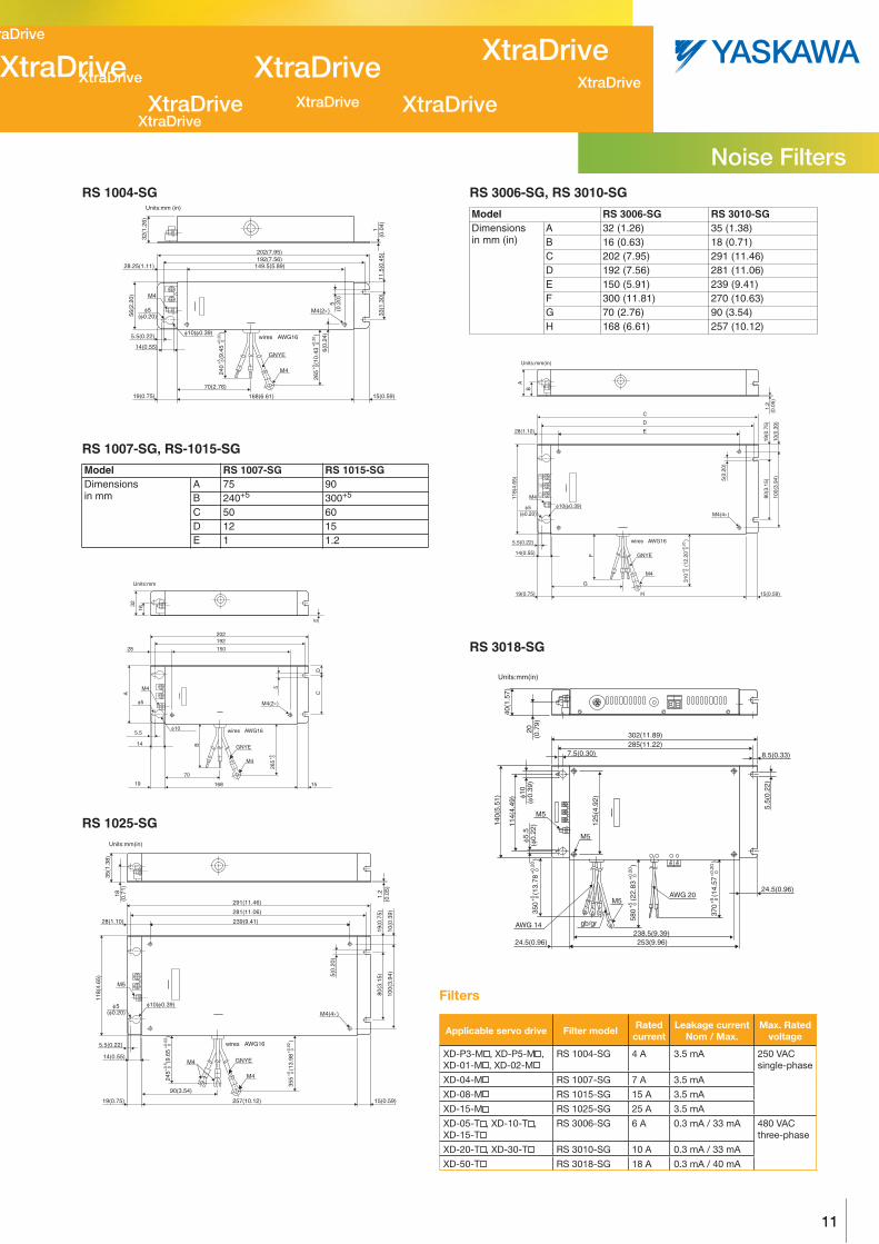
RS 1004-SG
RS 1007-SG, RS-1015-SG
RS 1025-SG
RS 3006-SG, RS 3010-SG
RS 3018-SG
Model RS 1007-SG RS 1015-SGDimensionsin mm
A 75 90B 240+5 300+5
C 50 60 D 12 15E 1 1.2
32(1
.26)
56(2
.20)
33(1
.30)
6(0.
24)
5(0
.20)
265
(10.
43
)
+5
0+
0.20
0
240
(9.4
5
)
+5
0+
0.20
0
11.5
(0.4
5)1
(0.0
4)
202(7.95)192(7.56)
149.5(5.89)
168(6.61)
M4
GNYE
wires AWG16
M4(2×)
70(2.76)
19(0.75)
14(0.55)
5.5(0.22)
M4
φ5(φ0.20)
φ10(φ0.39)
15(0.59)
28.25(1.11)
Units:mm (in)
M4
GNYE
M4
φ5
φ10 wires AWG16
265
B
C
5
D
A32
E
+5
0
16819
14
5.5
15
70
15028
192202
M4(2×)
Units:mm
16
M4
M4
M5
5.5(0.22)
14(0.55)
19(0.75) 257(10.12) 15(0.59)
90(3.54)
28(1.10) 239(9.41)
281(11.06)
291(11.46)
GNYE
wires AWG16
355
(13.
98
)
35(1
.38)
118(
4.65
)
18(0
.71)
1.2
(0.0
5)
5(0.
20)
10(0
.39)
19(0
.75)
80(3
.15)
100(
3.94
)
+5
0+
0.02
0
245
(9.6
5
)
+0.
5 0
+0.
02 0
φ5(φ0.20)
φ10(φ0.39)
M4(4×)
Units:mm(in)
Model RS 3006-SG RS 3010-SGDimensionsin mm (in)
A 32 (1.26) 35 (1.38)B 16 (0.63) 18 (0.71)C 202 (7.95) 291 (11.46)D 192 (7.56) 281 (11.06)E 150 (5.91) 239 (9.41)F 300 (11.81) 270 (10.63)G 70 (2.76) 90 (3.54)H 168 (6.61) 257 (10.12)
M4
M4
GNYE
L1L2
L35.5(0.22)
14(0.55)
19(0.75) H 15(0.59)
G
28(1.10)
D
E
C
wires AWG16
310
(12.
20
)
A11
8(4.
65)
B
1.2
(0.0
5)
5(0.
20)
10(0
.39)
19(0
.75)
80(3
.15)
100(
3.94
)
+5
0+
0.20
0
F
φ5(φ0.20)
φ10(φ0.39)
M4(4×)
Units:mm(in)
M5
M5
M5
gb/gr238.5(9.39)
AWG 20
253(9.96)24.5(0.96)
AWG 14
7.5(0.30)
302(11.89)285(11.22)
40(1
.57)
20(0
.79)
370
(14.
57
)
+5
0+
0.20
0
350
(13.
78
)
+5
0+
0.20
0
580
(22.
83
)
+5
0+
0.20
0
φ10
(φ0.
39)
140(
5.51
)
114(
4.49
)
125(
4.92
)
φ5.5
(φ0.
22)
24.5(0.96)
8.5(0.33)
5.5(
0.22
)
Units:mm(in)
Filters
Applicable servo drive Filter model Rated current
Leakage currentNom / Max.
Max. Rated voltage
XD-P3-M , XD-P5-M , XD-01-M , XD-02-M
RS 1004-SG 4 A 3.5 mA 250 VAC single-phase
XD-04-M RS 1007-SG 7 A 3.5 mA
XD-08-M RS 1015-SG 15 A 3.5 mA
XD-15-M RS 1025-SG 25 A 3.5 mA
XD-05-T , XD-10-T , XD-15-T
RS 3006-SG 6 A 0.3 mA / 33 mA 480 VAC three-phase
XD-20-T , XD-30-T RS 3010-SG 10 A 0.3 mA / 33 mA
XD-50-T RS 3018-SG 18 A 0.3 mA / 40 mA
Noise Filters

XtraDriveXtraDrive
XtraDriveXtraDrive
XtraDriveXtraDrive XtraDrive
XtraDrive XtraDrive
XtraDrive
12 YASKAWA XtraDrive12 YASKAWA XtraDrive
XtraDrive
XtraDrive
XtraDrive
Single-phase, 230 VAC
*1 The time constant for the primary filter is 47 µs.*2 Connect when using an absolute encoder.*3 Used only with an absolute encoder.*4 Regenerative resistor can be connected between B1 and B2.*6 TI stands for Texas Instruments Inc.
4
3
1
1
XtraDrive
Amount of phase-S rotationSerial data outputApplicable line receiverSN75175 manufactured by Texas Instruments or the equivalent corresponding to MC3486
Connect shield to connector shell.
PG dividing ratio outputApplicable line receiverSN75175 manufactured by Texas Instruments or the equivalent corresponding to MC3486
Running output(ON when the motor speed exceeds the settings.)
Servo ready output(ON when ready)
Servo alarm output(OFF for an alarm)
Photocoupler outputMax. operating voltage:30 VDCMax. operating current: 50 mA DC
Speed coincidence detection(ON when speed coincides.)
Alarm code outputMax. operating voltage:30 VDCMax. operating current:20 mA DC
Servo ON(Servo ON when ON)
Reverse run prohibited(Prohibited when OFF)
Forward run prohibited(Prohibited when OFF)
Alarm reset(Reset when ON)
Reverse current limit(Limit when ON)
Forward current limit(Limit when ON)
P control(P control when ON)
SEN signal input∗2
Backup battery(2.8 to 4.5 V)
∗2
Position reference
Open-collectorreferencePower supply
Speed reference(±2 to ±10 V/rated motor speed)
Torque reference(±1 to ±10 V/rated torque)
Be sure toground
Be sure to prepare the end ofthe shielded wire properly
Optical encoder
Servo motor
Be sure to attach a surge suppressor to the excitationcoil of the magnetic contactor and relay
Alarm processingPowerOff
PowerONNoise filter
Single-phase 200 to 230 VAC
Installation

XtraDrive XtraDrive
XtraDrive
XtraDrive
XtraDriveXtraDriveXtraDrive
XtraDrive
XtraDrive XtraDrive
XtraDrive
XtraDrive
XtraDrive
XtraDrive
1313
Three-phase, 400 VAC
*1 The time constant for the primary filter is 47 µs.*2 Connect when using an absolute encoder.*3 Used only with an absolute encoder.*4 For using an external regenerative resistor, connect it between B1 and B2.*5 The 24VDC power is supplyed by the user.*6 TI stands for Texas Instruments Inc.
L1 L2 L3
4
1
1
3
XtraDrive
Be sure to prepare the end ofthe shielded wire properly
Optical encoder
Servo motor
Amount of phase-S rotationSerial data outputApplicable line receiverSN75175 manufactured by Texas Instruments or the equivalent corresponding to MC3486
PG dividing ratio outputApplicable line receiverSN75175 manufactured by Texas Instruments or the equivalent corresponding to MC3486
Running output(ON when the motor speed exceeds the settings.)
Servo ready output(ON when ready)
Servo alarm output(OFF for an alarm)
Photocoupler outputMax. operating voltage:30 VDCMax. operating current: 50 mA DC
Speed coincidence detection(ON when speed coincides.)
Alarm code outputMax. operating voltage:30 VDCMax. operating current:20 mA DC
Connect shield to connector shell.
Servo ON(Servo ON when ON)
Reverse run prohibited(Prohibited when OFF)
Forward run prohibited(Prohibited when OFF)
Alarm reset(Reset when ON)
Reverse current limit(Limit when ON)
Forward current limit(Limit when ON)
P control(P control when ON)
SEN signal input∗2
Backup battery(2.8 to 4.5 V)
∗2
Position reference
Open-collectorreferencePower supply
Speed reference(±2 to ±10 V/rated motor speed)
Torque reference(±1 to ±10 V/rated torque)
Be sure toground
Be sure to attach a surge suppressor to the excitationcoil of the magnetic contactor and relay
Alarm processingPowerOff
PowerONNoise filter
Three-Phase 380 to 480 VAC
Power Supply*5
Installation

XtraDriveXtraDrive
XtraDriveXtraDrive
XtraDriveXtraDrive XtraDrive
XtraDrive XtraDrive
XtraDrive
14 YASKAWA XtraDrive14 YASKAWA XtraDrive
XtraDrive
XtraDrive
XtraDrive
Note: The symbols jklmn ... show the recommended sequence to select the components for a servo system.
25
6
3
4
7
Filter8
11
9
9
9
1 SGMAH / SGMPHServomotor
XtraDriveServo Drives
Terminal block
NS115
SW1
SW2
AR
CN6A
CN6B
CN4
Option unit
Analog monitor cable
Linear servomotorwith iron core
Linear scale
Serial converter
SGMGH / SGMSH / SGMUH Servomotor
Encoder cable
Encoder cable
Encoder cable
Power cable
Power cable
Power cable
General purpose cable
I/Osignals
Personal computer (PC)
SGL LINEARServomotor
PROFIBUS network
(XtraDrive models withembedded PROFIBUS)
XtraDrive (Analog/Pulse reference)
Installation

XtraDrive XtraDrive
XtraDrive
XtraDrive
XtraDriveXtraDriveXtraDrive
XtraDrive
XtraDrive XtraDrive
XtraDrive
XtraDrive
XtraDrive
XtraDrive
1515
Servo motors, power & encoder cables
Servo drives
Note: j Refer to the Sigma-II-catalog KAE S800-32D.
Symbol Specifications XtraDrive XtraDrive-E with electronic CAM
XtraDrive-DP with PROFIBUS
XtraDrive-DP-E with PROFIBUS and electronic
CAM
Compatible servo motors 1
Sigma-II rotary Sigma linear motors
2 1 phase 200 VAC
30 W XD-P3-MN01 XD-P3-MN01-E XD-P3-MSD0 XD-P3-MSD0-E SGMAH-A3A -
50 W XD-P5-MN01 XD-P5-MN01-E XD-P5-MSD0 XD-P5-MSD0-E SGMAH-A5D SGLGW-30A050
100 W XD-01-MN01 XD-01-MN01-E XD-01-MSD0 XD-01-MSD0-E SGMAH-01A ,SGMPH-01A
SGLGW-30A080 ,SGLGW-40A140
200 W XD-02-MN01 XD-02-MN01-E XD-02-MSD0 XD-02-MSD0-E SGMAH-02A ,SGMPH-02A
SGLFW-20A ,SGLFW-35A120 ,SGLGW-40A253A ,SGLGW-60A140
400 W XD-04-MN01 XD-04-MN01-E XD-04-MSD0 XD-04-MSD0-E SGMAH-04A ,SGMPH-04A
SGLGW-40A365A ,SGLGW-60A253A
750 W XD-08-MN XD-08-MN00-E XD-08-MSD0 XD-08-MSD0-E SGMAH-08A ,SGMPH-08A
SGLFW-35A230 ,SGLFW-50A200 ,SGLGW-60A365A
1.5 kW XD-15-MN XD-15-MN00-E - - SGMPH-15A SGLFW-50A380 ,SGLFW-1ZA200 ,SGLGW-90A200A
25
6
3
4
Filter8
11
9
9
9
1 SGMAH / SGMPHServomotor
XtraDriveServo Drives
Terminal block
Analog monitor cable
Linear servomotorwith iron core
Linear scale
Serial converter
SGMGH / SGMSH / SGMUH Servomotor
Encoder cable
Encoder cable
Encoder cable
Power cable
Power cable
Power cable
General purpose cable
I/Osignals
Personal computer (PC)
SGL LINEARServomotor
PROFIBUS connector
(CN6)
RS-232/RS-422Communication
Node Address
XtraDrive-DP (PROFIBUS embedded)
Installation
XtraDriveXtraDrive
XtraDriveXtraDrive
XtraDriveXtraDrive XtraDrive
XtraDrive XtraDrive
XtraDrive
16 YASKAWA XtraDrive16 YASKAWA XtraDrive
XtraDrive
XtraDrive
XtraDrive
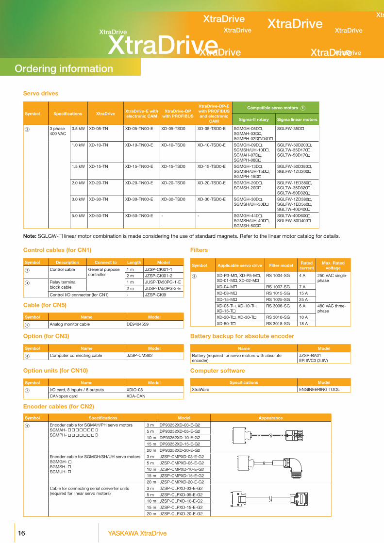
Symbol Specifications Model Appearance
9 Encoder cable for SGMAH/PH servo motorsSGMAH- DSGMPH- D
3 m DP93252XD-03-E-G2
5 m DP93252XD-05-E-G2
10 m DP93252XD-10-E-G2
15 m DP93252XD-15-E-G2
20 m DP93252XD-20-E-G2
Encoder cable for SGMGH/SH/UH servo motorsSGMGH- SGMSH- SGMUH-
3 m jZSP-CMPXD-03-E-G2
5 m jZSP-CMPXD-05-E-G2
10 m jZSP-CMPXD-10-E-G2
15 m jZSP-CMPXD-15-E-G2
20 m jZSP-CMPXD-20-E-G2
Cable for connecting serial converter units(required for linear servo motors)
3 m jZSP-CLPXD-03-E-G2
5 m jZSP-CLPXD-05-E-G2
10 m jZSP-CLPXD-10-E-G2
15 m jZSP-CLPXD-15-E-G2
20 m jZSP-CLPXD-20-E-G2
Encoder cables (for CN2)
Note: SGLGW- linear motor combination is made considering the use of standard magnets. Refer to the linear motor catalog for details.
Servo drives
Symbol Specifications XtraDrive XtraDrive-E with electronic CAM
XtraDrive-DP with PROFIBUS
XtraDrive-DP-E with PROFIBUS and electronic
CAM
Compatible servo motors 1
Sigma-II rotary Sigma linear motors
2 3 phase 400 VAC
0.5 kW XD-05-TN XD-05-TN00-E XD-05-TSD0 XD-05-TSD0-E SGMGH-05D ,SGMAH-03D ,SGMPH-02D /04D
SGLFW-35D
1.0 kW XD-10-TN XD-10-TN00-E XD-10-TSD0 XD-10-TSD0-E SGMGH-09D ,SGMSH/UH-10D ,SGMAH-07D ,SGMPH-08D
SGLFW-50D200 ,SGLTW-35D170 ,SGLTW-50D170
1.5 kW XD-15-TN XD-15-TN00-E XD-15-TSD0 XD-15-TSD0-E SGMGH-13D ,SGMSH/UH-15D ,SGMPH-15D
SGLFW-50D380 ,SGLFW-1ZD200
2.0 kW XD-20-TN XD-20-TN00-E XD-20-TSD0 XD-20-TSD0-E SGMGH-20D ,SGMSH-20D
SGLFW-1ED380 ,SGLTW-35D320 ,SGLTW-50D320
3.0 kW XD-30-TN XD-30-TN00-E XD-30-TSD0 XD-30-TSD0-E SGMGH-30D ,SGMSH/UH-30D
SGLFW-1ZD380 ,SGLFW-1ED560 ,SGLTW-40D400
5.0 kW XD-50-TN XD-50-TN00-E - - SGMGH-44D ,SGMSH/UH-40D ,SGMSH-50D
SGLTW-40D600 ,SGLFW-80D400
Option units (for CN10)
Option (for CN3)
Cable (for CN5)
Control cables (for CN1) Filters
Battery backup for absolute encoder
Computer software
Symbol Name Model
7 I/O card, 8 inputs / 8 outputs XDIO-08
CANopen card XDA-CAN
Symbol Name Model
6 Computer connecting cable jZSP-CMS02
Symbol Name Model
5 Analog monitor cable DE9404559
Symbol Description Connect to Length Model
3 Control cable General purpose controller
1 m jZSP-CKI01-1
2 m jZSP-CKI01-2
4 Relay terminal block cable
1 m jUSP-TA50PG-1-E
2 m jUSP-TA50PG-2-E
Control I/O connector (for CN1) - jZSP-CKI9
Symbol Applicable servo drive Filter model Rated current
Max. Rated voltage
8 XD-P3-M , XD-P5-M , XD-01-M , XD-02-M
RS 1004-SG 4 A 250 VAC single-phase
XD-04-M RS 1007-SG 7 A
XD-08-M RS 1015-SG 15 A
XD-15-M RS 1025-SG 25 A
XD-05-T , XD-10-T , XD-15-T
RS 3006-SG 6 A 480 VAC three-phase
XD-20-T , XD-30-T RS 3010-SG 10 A
XD-50-T RS 3018-SG 18 A
Name Model
Battery (required for servo motors with absolute encoder)
jZSP-BA01ER 6VC3 (3.6V)
Specifications Model
XtraWare ENGINEERING TOOL
Ordering information

XtraDrive XtraDrive
XtraDrive
XtraDrive
XtraDriveXtraDriveXtraDrive
XtraDrive
XtraDrive XtraDrive
XtraDrive
XtraDrive
XtraDrive
XtraDrive
1717
Power cables
Symbol Specifications Model Appearance
1 For 230 V servo motors without brakeSGMAH- A 1DSGMPH-(01/02/04/08)A 41D
3 m DP9325252-03G
5 m DP9325252-05G
10 m DP9325252-10G
15 m DP9325252-15G
20 m DP9325252-20G
For 230 V servo motors with brakeSGMAH- A CDSGMPH-(01/02/04/08)A 4CD
3 m DP9325253-03G
5 m DP9325253-05G
10 m DP9325253-10G
15 m DP9325253-15G
20 m DP9325253-20G
For 230 V servo motors without brakeSGMPH-15A 1D
3 m DP9325254-03G
5 m DP9325254-05G
10 m DP9325254-10G
15 m DP9325254-15G
20 m DP9325254-20G
For 230 V servo motors with brakeSGMPH-15A CD
3 m DP9325255-03G
5 m DP9325255-05G
10 m DP9325255-10G
15 m DP9325255-15G
20 m DP9325255-20G
For 400 V servo motors without brakeSGMAH- D 1DSGMPH- D 1D
3 m jZSP-CMM20D15-03G
5 m jZSP-CMM20D15-05G
10 m jZSP-CMM20D15-10G
15 m jZSP-CMM20D15-15G
20 m jZSP-CMM20D15-20G
For 400 V servo motors with brakeSGMAH- D CDSGMPH- D CD
3 m jZSP-CMM30D15-03G
5 m jZSP-CMM30D15-05G
10 m jZSP-CMM30D15-10G
15 m jZSP-CMM30D15-15G
20 m jZSP-CMM30D15-20G
For 400 V servo motorsSGMGH-(05/09/13)D SGMSH-(10/15/20)D SGMUH-(10/15)D for servo motors with brake a separate cable (jZSP-CMM02BR G) is needed
3 m jZSP-CMM02D15-03G
5 m jZSP-CMM02D15-05G
10 m jZSP-CMM02D15-10G
15 m jZSP-CMM02D15-15G
20 m jZSP-CMM02D15-20G
For 400 V servo motorsSGMGH-(20/30)D SGMSH-(30/40/50)D SGMUH-(30/40)D for servo motors with brake a separate cable (jZSP-CMM02BR G) is needed
3 m jZSP-CMM02D30-03G
5 m jZSP-CMM02D30-05G
10 m jZSP-CMM02D30-10G
15 m jZSP-CMM02D30-15G
20 m jZSP-CMM02D30-20G
For 400 V servo motorsSGMGH-44D for servo motors with brake a separate cable (jZSP-CMM02BR G) is needed
3 m jZSP-CMM02D44-03G
5 m jZSP-CMM02D44-05G
10 m jZSP-CMM02D44-10G
15 m jZSP-CMM02D44-15G
20 m jZSP-CMM02D44-20G
For 400 V servo motorsSGMGH-55D for servo motors with brake a separate cable (jZSP-CMM02BR G) is needed
3 m jZSP-CMM02D55-03G
5 m jZSP-CMM02D55-05G
10 m jZSP-CMM02D55-10G
15 m jZSP-CMM02D55-15G
20 m jZSP-CMM02D55-20G
Brake cable only.For 400 V servo motors with brakeSGMGH- D SGMSH- D SGMUH- D
3 m jZSP-CMM02BR- 03G
5 m jZSP-CMM02BR- 05G
10 m jZSP-CMM02BR- 10G
15 m jZSP-CMM02BR- 15G
20 m jZSP-CMM02BR- 20G
Ordering information

YASKAWA Europe GmbHHauptstraße 18565760 EschbornDeutschland / Germany
+49 6196 [email protected]
Specifications are subject to change without noticefor ongoing product modifications and improvements.© YASKAWA Europe GmbH. All rights reserved.
Literature No. YEU_MuC_XtraDrive_EN_v3_0211Printed in Germany February 2011


